Embed Size (px)
Citation preview

For subscription call SOFTbank Tehran, Phone: 66403879,66493070

PIPE DRAFTINGAND DESIGN
For subscription call SOFTbank Tehran, Phone: 66403879,66493070

This page intentionally left blank
For subscription call SOFTbank Tehran, Phone: 66403879,66493070

PIPE DRAFTINGAND DESIGN
Second Edition
Roy A. Parisher • Robert A. Rhea
Gulf Professional Publishingan imprint of Butterworth-Heinemann
Boston, Oxford, Auckland, Johannesburg, Melbourne, New Delhi
For subscription call SOFTbank Tehran, Phone: 66403879,66493070

Gulf Professional Publishing is an imprint of Butterworth-Heinemann.
Copyright © 2002 by Butterworth-Heinemann
-^ A member of the Reed Elsevier group
All rights reserved.
No part of this publication may be reproduced, stored in a retrieval system, or transmitted in anyform or by any means, electronic, mechanical, photocopying, recording, or otherwise, withoutthe prior written permission of the publisher.
6S Recognizing the importance of preserving what has been written, Butterworth-Heinemann printsits books on acid-free paper whenever possible.
Tj1 Butterworth-Heinemann supports the efforts of American Forests and the GlobalAT" R£Leaf program in its campaign for the betterment of trees, forests, and ourinn environment.
Library of Congress Cataloging-in-Publication Data
Parisher, Roy A.Pipe drafting and design / Roy A. Parisher, Robert A. Rhea-2nd ed.
p. cm.Includes index.ISBN 0-7506-7439-3 (alk. paper)1. Piping—Drawing—Handbooks, manuals, etc. 2. Piping—Design and construction—Handbooks, manuals, etc. I. Rhea, Robert A. II. Title.
TJ930 .P32 2001621.8'672—dc21
2001023633
British Library Cataloguing-in-Publication Data
A catalogue record for this book is available from the British Library.
The publisher offers special discounts on bulk orders of this book.For information, please contact:
Manager of Special SalesButterworth-Heinemann225 Wildwood AvenueWoburn, MA 01801-2041Tel: 781-904-2500Fax: 781-904-2620
For information on all Gulf Professional Publishing publications available, contact our WorldWide Web home page at: http://www.gulfpp.com
1 0 9 8 7 6 5 4 3 2 1
Printed in the United States of America
iv
For subscription call SOFTbank Tehran, Phone: 66403879,66493070

About the Cover
The 3D wire frame model on the cover is a detailed view of the pipingmodel used in this text and shown in the window on the back cover. Thismodel was created with PRO-PIPE™ and rendered in 3D Studio®.
vi
For subscription call SOFTbank Tehran, Phone: 66403879,66493070

For my parents, Archie and Joyce:Your love and support are endless.
I could never say "Thank you" enough for what you have given me. Roy
To Mary:Thank you for your help and support. Robert
v
For subscription call SOFTbank Tehran, Phone: 66403879,66493070

Contents
Acknowledgments ix Cast Iron Fittings 38Plastic Fittings 38
Preface x Review Quiz 39. . A A1 . A1 . Exercise Information 40
About the Authors xi -,, . ~ ~ . c . ,,Chapter 3 Drawing Exercises 41
Chapter 1 ^Chanter 4Overview of Pipe Drafting and Design 1 „ .
Types of Projects! Flange Basics 48Employers of Pipe Drafters and Designers 1 Ratmg FlanSes 48
Engineering and Construction Companies 1 Flange Facings 48Operating Companies 2 FlanSe TyPes 50
Architectural Engineering Companies 2 ° s
Construction Companies 2 Gaskets 57Fabrication Companies 2 Review °-uiz 61
Preparation for Piping Drafting 2 Exercise ^formation 63Technical Skills 3 ChaPter 4 Drawing Exercises 65
Personal Skills 3 „, . __ . ^ . . ChaptersCreation of Pipe Drawings 3 _T , fnValves 69Chapter 2 What Is a Valve? 69Steel Pipe 4 Common Valve Types 70History of Pipe 4 Valve Operators 81Piping Materials 4 Review Quiz 82Manufacturing Methods 4 Chapter 5 Drawing Exercises 86Sizing of Pipe 5Wall Thickness 6 Chapter 6Methods of Joining Pipe 6 Mechanical Equipment 90Cast Iron Pipe 8 Types of Equipment 90Plastic Pipe 10 Equipment in Use 100Drawing Pipe 10 Equipment Terminology 101Review Quiz 12 Vendor Data Drawings 103
Drawing Equipment 103Chapter 3 Review Quiz 108Pipe Fittings 13 Chapter 6 Drawing Exercises 11090° Elbows 1345° Elbows 19 Chapter 7Weld Tee 22 Flow Diagrams and Instrumentation 111The Stub-In 26 Uses of Flow Diagrams 111Coupling 27 Type of Flow Diagrams 111Reducers 28 Flow Diagram Instruments 114Weld Cap 31 Piping Symbols 117Use of Fittings 31 Flow Plan Arrangement 117Screwed and Socket-Weld Fittings 33 Review Quiz 118Pipe Nipples 33 Exercise Information 119Flanged Fittings 37 Chapter 7 Drawing Exercises 120
vii
For subscription call SOFTbank Tehran, Phone: 66403879,66493070

Chapter 8 Control Valve Manifolds 204Codes and Specifications 123 Utility Stations 206Codes 123 Meter Runs 206Specifications 123 Sewer and Underground Piping Systems 207Specification Classes 125 Review Quiz 209Abbreviations 126Piping Abbreviations 126 Chapter 13Review Quiz 132 PiPin8 Isometrics 210
What Is an Isometric? 210Chapter 9 Drawing Piping Isometrics 216Equipment Layout 133 Isometric Dimensions, Notes, and Callouts 218Plant Coordinate Systems 133 Isometric Offsets 219Site Plans 136 Review Quiz 226Unit Plot Plan 136 Drawing Exercises 227Equipment Location Drawing 136Foundation Location Drawing 136 Chapter 14Piping Drawing Index 141 Customizing AutoCAD 231Review Quiz 142 Creating Command Aliases 231
Using AutoLisp 232Chapter 10 Review Quiz 236Piping Arrangement Drawings, Sections, andElevations 143 Chapter 15Arrangement Drawings 143 Three-dimensional Modeling of PipingResponsibilities of the Piping Designer 143 Systems 237Information Sources for Piping Arrangement Drawings 143 Advantages of 3D Modeling 237Layout Procedures 144 Checking for Interferences 237Piping Arrangement Drawing Layout 144 Generating Drawings Automatically from a Model 241Dimensioning 186 Generating Isometric Drawings Automatically 241Piping Sections and Elevations: What Are They? 187 Computer-Aided Engineering of Models 241Detail Drawings 188 Choosing a Modeling Software Package 241Review Quiz 192 Building a 3D Model Using AutoPlant 242Exercises: Plans, Elevations, and Sections 193
Appendix AChapter 11 Dimensional Data 256Standard Piping Details 194Pipe Rack Spacing 194 Appendix BDrawing Pipe in the Rack 194 Review of Lettering 292Pipe Flexibility 195 . ,. „™ t u * c 1 n-7 Appendix CPlanning for Heat Expansion 197 A , . . A „ _ . _ „ .„. . u ino Alphabet of Lines 294Pipe Anchors 198 r
Pipe Insulation Shoes 198 Appendix DPipe Guides 198 Review of Math 295
Field Supports 199Dummy Supports 200 Appendix EHanger Rods 200 Use of the Calculator 296Spring Hangers 201Pick-up Pipe Supports 201 Appendix FReview Quiz 202 Architect's Scale 299
Chapter 12 Glossary 300Piping Systems 203Plant Utilities 203 Index 308
viii
For subscription call SOFTbank Tehran, Phone: 66403879,66493070

Acknowledgments
Dr. Stanley Ebner: Support Roger Parisher: SouthwestStephan Miller: 3D project model Fastners, Hodell-Natco, Inc.Linda Ferrell: Rebis Alan Human: Flexitallic, Inc.Joe Martinez: Technical Editing. Gene Eckert: EC AD, Inc., Pro-PIPER. B. Herrscher: Nisseki Chemical 3D model, Chapter 15
Texas, Inc. Anthony W. Horn: Chapter 15
The material, applications, and routines presented in this book have beenincluded for their instructional value. They have been tested for accuracy, butare not guaranteed for any particular purpose. The publisher and authors donot offer any representations or warranties, nor do they accept any liabilitieswith respect to the material, applications, or routines.
TrademarksAutoCAD® is registered in the U.S. Patent and Trademark office by Autodesk,
Inc.AutoLISP® is registered in the U.S. Patent and Trademark office by Autodesk,
Inc.
ACAD.MNU Version 2000Copyright © 1986, 1987, 1988, 1989, 1990, 1991, 1992, 1994, 1996, 1997,1998 by Autodesk, Inc.Autodesk provides this program "as is" and with all fault. Autodesk spe-cifically disclaims any implied warranty of merchantability or fitness for aparticular use. Autodesk , Inc. does not warrant that the operation of the pro-gram will be uninterrupted or error free.AutoPLANT is registered in the U.S. Patent and Trademark office byRebis, Inc.
ix
For subscription call SOFTbank Tehran, Phone: 66403879,66493070

Preface
This book provides students with the basic skills they will need to preparea wide range of piping drawings. It presents a step-by-step approach to thebasic fundamentals students will need to begin a successful career in indus-trial drafting and design. Chapter One gives a quick overview of the manyopportunities in drafting and design for those who master the basic skills pre-sented in the following chapters. Then each chapter builds on the precedingone. It is necessary therefore to master the concepts in a given chapter beforegoing on to the next one. Each chapter concludes with exercises and ques-tions designed to help students review and practice the concepts presented inthat chapter.
X
For subscription call SOFTbank Tehran, Phone: 66403879,66493070

About the Authors
Roy A. Parisher is a professor in the engineering design graphics depart-ment at San Jacinto College in Pasadena, Texas, where he has taught for over20 years.
Robert A. Rhea is a former associate professor of engineering technologyat the University of Houston Downtown, Houston, Texas.
VI
For subscription call SOFTbank Tehran, Phone: 66403879,66493070

This page intentionally left blank
For subscription call SOFTbank Tehran, Phone: 66403879,66493070

Overview of PipeDrafting andDesign
In the design of an industrial facility, engineers • fertilizer plantsdevelop process flow sheets, set up project specifications • pipe systems for hospitals and high-riseand design or select equipment. The design drafters use office buildingsthe information supplied by engineers and equipment • pharmaceutical plantsvendors and applies the knowledge and experience • food and beverage plantsgained in the office and field to design and layout the • synthetic fuel plantsfacility. • offshore platforms
In the design and layout of an industrial complex, • pipeline installationsthousands of piping drawings are needed to provide • water treatment facilitiesdetailed information to the craftsmen who will construct • environmental waste disposalthe facility. Facility design and layout must meet the cus-tomer's expectations as well as comply with safety codes, Many projects will be designed for construction ingovernment standards, client specifications, budget, and other countries, offering the designer opportunities forstart-up date. travel. Each project presents drafters and designers with
The piping group has the main responsibility for the opportunities to expand their skills and knowledge of thedesign and layout of the facility. Drafters and designers field of piping design,must coordinate their efforts with the civil, structural,electrical, and instrumentation groups throughout the nRAFTFRQ AAII1 nFQIHNFRSdesign process The piping group must provide each EMPLOYERS OF PIPE DRAFTERS AND DESIGNERSdesign group the necessary information needed to com-plete their part of the project and have the complete set of Employers seek to hire pipe drafters and designersplan and construction drawings finished on time. During range for various companies. Among them are:this time, it may be necessary for designers to visit theplant construction site to establish tie-ins or verify infor- • engineering and construction companiesmation necessary to complete the design. • operating companies
• architectural firms
Tvpcc HF PRn IFPT<5 * construction companiesI T rta ur rifUJtb I d . fabrication companies
est range of opportunities of any field of design drafting. ENGINEERING AND CONSTRUCTION COMPANIESThe types of design projects one could expect to work onmay include: Engineering and construction companies provide the
design and layout of a facility. Many clients award the• power plants engineering and design phase of a project to one firm and• petrochemical complex the construction phase to another. While many operating• pulp and paper plants companies have a small engineering staff who handle the
1
For subscription call SOFTbank Tehran, Phone: 66403879,66493070

2 Pipe Drafting and Design
day-to-day needs of changing and updating drawings, • purchasingsuch as adding a pump or other small equipment, they do • material controlnot have the manpower to design and engineer a grass- • material take-offroots plant or major add-on. Total plant design and con- • estimatingstruction may require hundreds of workers and may entail • pipe stress and pipe supportsyears in the design and construction of the plant. • CAD support
• project management
OPERATING COMPANIES
CONSTRUCTION COMPANIESOperating companies are the clients who engage in the
day-to-day operation of a facility and who seek out theservices of engineering and construction firms when Many firms specialize only in the construction ofexpanding existing facilities or constructing a new Plants- Here the PiPing designer may actually help over-project. Many operating companies keep a small engi- see the construction of the facility while working underneering staff in the home office or at the plant job site. the supervision of a construction superintendent. TheDesigners are exposed to the day-to-day operations of the designer is often called upon to make small designfacility and follow the construction of small projects. This changes resulting from mistakes discovered during thesituation may require that the designer have a broad range construction phase or as customers dictate changes. Atof knowledge and skills, as he or she often may be asked the completion of the project, drawings are updated toto design and lay out the complete project. The design reflect me many changes made during construction,may prepare foundation, steel, and piping drawings as These drawings are called or referred to as "as-built"needed, and may even do some electrical and instrumen- drawings,tation design when required.
FABRICATION COMPANIESARCHITECTURAL ENGINEERING COMPANIES
Fabrication companies fabricate and ship much of thePipe drafters and designers employed by architectural PiPmg necessary for the construction of the plant to the
engineering companies apply their skills to commercial Job site- ManY fabrication drawings called piping spooland high-rise buildings. These may include multi-story drawings must be prepared. These drawings give detailedoffice buildings, hospitals, condominiums, shopping dimensions from which welders can fabricate the pipe,malls, or other similar structures. In addition to the indus- The drafter who prepares these drawings will not betrial piping components such as those found in a typical required to have an extensive background in plant layout,boiler room, supplementary piping systems must be however, the position provides the drafter with valuabledesigned for plumbing, HVAC, and drainage systems that experience in materials and material science,are also required in these structures.
Pipe drafters and designers must therefore be able to PREPARATION FOR PIPING DRAFTINGdevelop drawings such as:
• piping flow sheets Students must have a good background in basic draft-• plot plans ing before pursuing a job in the field of pipe drafting and• equipment location drawings design. Students should have good manual drafting skills• piping arrangement drawings related to line quality and freehand lettering. At the same• piping isometric drawings time, students must acquire the necessary background to
use the latest software tools such as AutoCAD and PRO-Learning the "language" of piping prepares employees PIPE, which allows them to be more productive. As stu-
for advancement to other departments within the engi- dents advance, they will use a variety of sophisticatedneering firms. These departments include not only the software packages, ranging from basic CAD software todrafting and design departments but also: 3D solid modeling.
For subscription call SOFTbank Tehran, Phone: 66403879,66493070

Overview of Pipe Drafting and Design 3
TECHNICAL SKILLS and guidelines, and use an H or F lead for other line workand lettering needs. Line thickness also has an important
The drafter must become familiar with the uses of fit- role on P1?1^ drawings. A .7mm or wider lead holder istings, flanges, valves, and equipment. This will require commonly used on major elements of the drawing such astime and effort to master the recognition of symbol shapes P1?6 and lettering. Background components such asas well as research to find the dimensions needed to draw equipment, foundations, support structures, and dimen-these items to scale. Often beginning drafters start out sion lines are typically drawn with a .5mm lead,making corrections to existing drawings. This is where One cannot stress enouSh the importance of qualitythey acquire the skills and knowledge of piping that will line work and lettering. Manual drawings are constantlyallow them to advance to the position of piping designer. slid in and out of the flle drawers and run through blue-
Drafters who have held field positions as pipe fitters Print machines. This requires that lettering and line workor welders find this real world experience valuable. be neat and of g°od <luallty to maintam clarity of dimen-Many times this experience allows them to advance at a sions and callouts.faster pace.
CAD Software Tools
PERSONAL SKILLS There are many djfferent CAD software tools on themarket today. Many engineering companies require
Students should not neglect their speaking, writing, their designers to know and use several different CADand math skills. Every company appraises future employ- software tools. Engineering companies must be pre-ees during the interview process, not only for technical pared to accommodate the client's preference of CADskills, but also for the personal skills needed to interact programs. In today's marketplace, the pipe drafter andwith the engineering team. This interaction is a must for designer should learn how to use AutoCAD andthe team in order to complete the job with a minimal MicroStation. These two CAD programs are widelyamount of mistakes. Honesty, reliability, dedication to used by engineering firms in the United States andimproving skills, and a positive attitude contribute much throughout the worldto the successful career of the designer. You will be a As with CAD programs> there ^e several piping soft-member of a design team. You may work with people ware programs on the market today. Engineering firmsfrom countries all over the world. Getting along with fel- must be reSpOnsive to the needs and preferences of theirlow workers has much to do with successful yearly eval- dients Software developers steadily develop, revise, andnations and compensation for your efforts. refme programs to meet the demands of engineering and
design firms. As with any business each software devel-CREATION OF PIPE DRAWINGS oper tries to incorporate the special features and amenities
into their software package that will attract potentialManual Drafting users. Often clients will dictate that all bid packages sub-
mitted for a project shall be completed using a particularManual drafters use a variety of triangles, plastic tern- piping software program. Most piping software packages
plates (circle and ellipse), and scales to layout piping provide the end user with the ability to develop threedrawings. While electric erasers are not necessary, they dimensional computer models of the completed facility,make the job of erasing much easier and faster. Pencils Software packages such as AutoPLANT, PDS, andand leads come in a wide range of sizes and shapes. PDMS, among others, have the intelligence to createDrafters usually use a 4H lead to draw projection lines either 2D or 3D drawings.
For subscription call SOFTbank Tehran, Phone: 66403879,66493070

Steel Pipe
HISTORY OF PIPE
Long ago someone decided carrying water from thenearby stream back to his or her dwelling was time-consuming and laborious. Ingenuity gave birth to inven-tion and the pipe was born. Using the natural resourcesavailable, early humans probably fashioned the first pipefrom bamboo. Needing to move larger amounts of water,they later hollowed out logs. Egyptian and Aztec civiliza-tions made pipe from clay. The first metallic pipes weremade by the Greeks and Romans from lead and bronze.The use of iron as a material to manufacture pipe cameabout with the invention of gun powder. Gun powder, ofcourse, is not used to make the iron, but gun powdernecessitated the invention of stronger gun barrels. Ironpipes soon followed. Eventually exotic metals weredeveloped, and pipe became the highly specialized prod-uct it is today.
PIPING MATERIALS
Applied in a general sense, pipe is a term used to des-ignate a hollow, tubular body used to transport any com-modity possessing flow characteristics such as thosefound in liquids, gases, vapors, liquefied solids, and finepowders.
A comprehensive list of the materials used to manu-facture pipe would be quite lengthy. Some of the materi-als include concrete, glass, lead, brass, copper, plastic,aluminum, cast iron, carbon steel, and steel alloys. Withsuch a broad range of materials available, selecting one tofit a particular need can be confusing. A thorough under-standing of the pipe's intended use is essential. Eachmaterial has limitations that may make it inappropriatefor a given application. Throughout this text we will baseour discussion on carbon steel pipe, the most commonmaterial used in the piping industry.
MANUFACTURING METHODS
Carbon steel pipe can be manufactured using severaldifferent techniques, each of which produces a pipewith certain characteristics. These characteristics includestrength, wall thickness, corrosion resistance, and tem-perature and pressure limitations. For example, pipeshaving the same wall thickness but manufactured by dif-ferent methods may vary in strength and pressure limits.The manufacturing methods we will mention includeseamless, butt-welded, and spiral-welded pipe.
Seamless pipe is formed by piercing a solid, near-molten,steel rod, called a billet, with a mandrel to produce a pipethat has no seams or joints. Figure 2-1 depicts the manu-facturing process of seamless pipe.
Figure 2-1. Seamless pipe.
Butt-welded pipe is formed by feeding hot steel platethrough shapers that will roll it into a hollow circularshape. Forcibly squeezing the two ends of the platetogether will produce a fused joint or seam. Figure 2-2shows the steel plate as it begins the process of formingbutt-welded pipe.
Figure 2-2. Butt-welded pipe.
For subscription call SOFTbank Tehran, Phone: 66403879,66493070

Least common of the three methods is spiral-weldedpipe. Spiral-welded pipe is formed by twisting strips ofmetal into a spiral shape, similar to a barber's pole, thenwelding where the edges join one another to form a seam.This type of pipe is restricted to piping systems using lowpressures due to its thin walls. Figure 2-3 shows spiral-welded pipe as it appears before welding.
Figure 2-3. Spiral-welded pipe.
Figure 2-4. Carbon steel pipe.
Figure 2-4 shows the three pipes previously describedin their final form.
Each of the three methods for producing pipe has itsadvantages and disadvantages. Butt-welded pipe, forexample, is formed from rolled plate that has a more uni-form wall thickness and can be inspected for defects priorto forming and welding. This manufacturing method isparticularly useful when thin walls and long lengths areneeded. Because of the welded seam, however, there isalways the possibility of defects that escape the numer-ous quality control checks performed during the manu-facturing process.
As a result, The American National Standards Institute(ANSI) developed strict guidelines for the manufacture ofpipe. Pressure Piping Code B 31 was written to governthe manufacture of pipe. In particular, code B31.1.0assigns a strength factor of 85% for rolled pipe, 60% forspiral-welded and 100% efficiency for seamless pipe.
Generally, wider wall thicknesses are produced by theseamless method. However, for the many low-pressure
Steel Pipe 5
uses of pipe, the continuous welded method is the mosteconomical. Seamless pipe is produced in single and dou-ble random lengths. Single random lengths vary from16'-0" to 20'-0" long. Pipe 2" and below is found in dou-ble random lengths measuring 35'-0" to 40'-0" long.
SIZING OF PIPE
Just as manufacturing methods differ, there are alsodifferent ways to categorize the size of a pipe. Pipe isidentified by three different size categories: nominalpipe size, outside diameter, and inside diameter (seeFigure 2-5).
Figure 2-5. Pipe diameters.
Nominal pipe size (NFS) is used to describe a pipe byname only. In process piping, the term nominal refers tothe name of the pipe, much like the name 2 x 4 given to apiece of lumber. The lumber does not actually measure2" x 4", nor does a 6" pipe actually measure 6" in diame-ter. It's just an easy way to identify lumber and pipe.
Outside diameter (OD) and inside diameter (ID), astheir names imply, refer to pipe by their actual outside andinside measurements.
Pipe i/g" to 12" has an outside diameter greater than itsnominal pipe size, while pipe 14" and above has an out-side diameter equal to its nominal pipe size.
In process piping, the method of sizing pipe maintainsa uniform outside diameter while varying the inside diam-eter. This method achieves the desired strength necessaryfor pipe to perform its intended function while operatingunder various temperatures and pressures.
For subscription call SOFTbank Tehran, Phone: 66403879,66493070

6 Pipe Drafting and Design
WALL THICKNESS
Wall thickness is a term used to describe the thicknessof the metal used to make a pipe. Wall thickness is alsocommonly referred to as a pipe's weight. Originally man-ufactured in weights known as standard, extra strong, anddouble extra strong, pipe has since increased in complex-ity with the development of new chemical processes.Commodities with ever-changing corrosive properties,high temperatures, and extreme pressures have necessi-tated the development of numerous additional selectionsof wall thicknesses for pipe. Now called schedules, theseadditional wall thicknesses allow a pipe to be selected tomeet the exact requirements needed for safe operation.An example of this variance in wall thickness is shown inFigure 2-6.
Figure 2-6. Pipe thickness.
As you can see in Table 2-1, nominal size is not equalto either the actual OD or the ID for pipe 12" and smaller.It is simply a convenient method to use when referring topipe. As a piping drafter, you should be aware however,pipe 14" and larger is identified by its actual outside mea-surement. The chart in Table 2-1 shows typical pipe diam-eters and wall thicknesses.
The following formula can be used to calculate a pipe'sinside diameter (ID):
ID = OD minus (2 x WALL THICKNESS)
Before selecting pipe, careful consideration must begiven to its material, temperature and pressure allow-ances, corrosion resistance, and more. Buying and install-ing pipe that does not meet the minimum requirementscan be dangerous and deadly. Using pipe that far exceedswhat is required to do the job can result in tremendouscost overruns.
METHODS OF JOINING PIPE
There are several methods for joining pipe together.The three methods we will focus on are those mostwidely used in piping systems made of carbon steel, asshown in Figure 2-7. They are butt-welded (BW),screwed (Scrd), and socket-weld (SW). Later in the chap-ter, cast iron and plastic pipe uses will be discussed.
Table 2-1Carbon Steel Pipe Wall Thickness
NOMINAL PIPESIZE
IN. MM
2
3
4
6
8
10
12
14
16
18
50.8
76.2
101
152
203
254
304
355
406
457
OUTSIDEDIAMETER
IN. MM
2.3
3.5
6 4.5
4 6.6
2 8.6
10.
8 12.
6 14
.4 16
.2 18
75 60.3
88.9
114
25 168
25 219
75 273
75 323
355
406
457
STANDARD
IN. MM
.15
.21
3 .23
3 .28
.32
.36
9 .37
.6 .37
.4 .37
.2 .37
4 3.91
6 5.48
7 6.02
0 7.12
2 8.17
5 9.27
5 9.52
5 9.52
5 9.52
5 9.52
EXTRA STRON
IN. MM
2 .21
6 .30
.33
.43
.50
.50
!5 .50
!5 .50
!5 .50
>5 .50
8 5.53
0 7.62
7 8.5E
2 10.£
0 12J
0 12.:
0 12.:
0 12.:
o 12.:o 12.:
G XX STRONG
IN. MM
> .43
.55
I .67
7 .86
'0 .87ro 1.070 1.0
'0707Q
6 11.0:
2 15.2^
4 17.12
4 21. 9^
5 22.2;
0 25.4
0 25.4
For subscription call SOFTbank Tehran, Phone: 66403879,66493070

Figure 2-7. Pipe joints.
Butt-Weld Connections
A butt-weld joint is made by welding the beveled ends oipipe together. Beveled ends (BE) indicate that the ends oithe pipe are not cut square, but rather are cut or ground tchave a tapered edge. In preparation for the welding process,a welder will separate two pieces of pipe by a Vie" space,known as a root gap. During the welding process, the twcends are drawn together and the V\^' gap disappears. If twcpieces of pipe 3'-0" long were welded together in this man-ner, the result would be a total length of 6'-0".
However, sometimes a back-up ring is used in criticalsituations. The back-up ring is used when there is a needto prevent the formation of weld icicles inside the pipe.The back-up ring creates a gap of Vs" between the twopieces of pipe. In this situation, the ring does not allow
Steel Pipe 7
the ends of the pipe to be drawn together and keeps themseparated by y%".
If two lengths of pipe measuring 3'-0" each werewelded together using a back-up ring, the result would bea total length of 6'-01/8". In this instance, the >/s" gapwould be shown when dimensioning the pipe. Otherwise,the root gap would not be considered at all. Figure 2-8shows the Vie" root gap and the resulting butt-weld joint.
Figure 2-8. Butt-weld joints.
Screwed or Threaded Connections
Another common means of joining pipe is the threadedend (TE) connection. Typically used on pipe 3" andsmaller, threaded connections are generally referred to asscrewed pipe. With tapered grooves cut into the ends of arun of pipe, screwed pipe and screwed fittings can easilybe assembled without welding or other permanent meansof attachment. Screwed pipe and its mating fittings will
Table 2-2American Standard and API Thread Engagement
For subscription call SOFTbank Tehran, Phone: 66403879,66493070

8 Pipe Drafting and Design
have threads that are either male or female. Male threads square, or perpendicular to, the long axis, unlike butt-are cut into the outside of a pipe or fitting, while female weld fittings that have beveled ends,threads are cut into the inside of the fitting.
As screwed pipe and fittings are assembled, a short PACT lonu DIDElength of pipe is drawn into the fitting. This connection WHO! inUli rirclength is called a thread engagement. When drawing anddimensioning screwed pipe, a piping drafter must be Not all piping systems require pipe designed to with-aware of this lost length of pipe. As the diameter of the stand me extreme conditions found in process pipingpipe increases, so will the length of the thread engage- faciiities< Cast iron pipe, which has been in use for centu-ment. Table 2-2 provides a chart indicating the thread ^ is used pTimari\y in gravity flow applications such asengagements for small bore pipe. storm and sanitary sewers, and waste and vent piping
installations. Residential, commercial, and industrialSocket-Weld Connections facilities routinely are built with some form of gravity
flow systems. The corrosion resistance properties of castThe third method of joining carbon steel pipe is socket iron pipe make it the ideal product for permanent below-
welding. When assembling pipe with socket-weld fit- ground gravity flow installations.tings, the pipe is inserted into the fitting before welding, The term cast iron refers to a large group of ferrousunlike a butt-weld connection that has the pipe and fitting metals. Cast irons are primarily alloys of iron that containplaced end-to-end. Inside the socket-weld fitting is a col- more than 2% carbon and 1% or more silicon. Cast iron,lar that prevents the pipe from being inserted too deeply like steel, does corrode. What makes cast iron different isinto the fitting. its graphite content. As cast iron corrodes, an insoluble
As with screwed connections, a short amount of pipe layer of graphite compounds is produced. The density andis lost when the socket-weld connections are made. adherent strength of these compounds form a barrierTable 2-3 provides the socket depths for pipe sizes around the pipe that prevents further corrosion. In steelthrough 3" in diameter. Before the weld is made, the pipe this graphite content does not exist, and the compoundsfitter will back the pipe off the collar approximately i/8" created during corrosion cannot bond together. Unable toto allow for heat expansion during the welding procedure. adhere to the pipe, they flake off and expose an unpro-Pipe used for socket-weld connections will be prepared tected metal surface that perpetuates the corrosion cycle,with a plain end. Plain end (PE) means the pipe is cut In tests of severely corroded cast iron pipe, the graphite
Table 2-3Forged Steel Socket Weld Fittings
For subscription call SOFTbank Tehran, Phone: 66403879,66493070

compounds have withstood pressures of several hundredpounds per square inch, although corrosion had actuallypenetrated the pipe wall. Considering the low cost of rawmanufacturing materials and the relative ease of manu-facture, cast iron is the least expensive of the engineer-ing metals. These benefits make cast iron the choiceapplication in environments that demand good corrosionresistance.
Joining Cast Iron Pipe
Cast iron pipe is grouped into two basic categories:hub and spigot, and hubless.
The hub, or bell, and spigot joint uses pipe with twodifferent end types. The hub end of the pipe has anenlarged diameter, thus resembling a bell. The spigotend of the adjoining pipe has a flat or plain-end shape.The spigot is inserted into the bell to establish a joint.Two methods of preventing leaks on bell and spigotjoints are compression and lead and oakum. The com-pression joint uses a one-piece rubber gasket to create aleak-proof seal. As shown in Figure 2-9, when the spigotend of the pipe is placed into the hub containing a gas-ket, the joint is sealed by displacing and compressing therubber gasket. Unlike welded pipe, this joint can absorbvibration and can be deflected up to 5° without leakageor failure.
The lead and oakum joint is made with oakum fiberand molten lead to create a strong, yet flexible, leak-proofand root-proof joint. When the molten lead is poured overthe waterproof oakum fiber, which is a loose, oil laden,
Figure 2-9. Compression joint.
Steel Pipe 9
hemp-like packing material, the joint becomes com-pletely sealed. Water will not leak out and, when usedunderground, roots cannot grow through the joints. SeeFigure 2-10.
Figure 2-10. Lead and oakum joint.
Hubless cast iron pipe uses pipe and fittings manufac-tured without a hub. The method of joining these pipe andfittings uses a hubless coupling that slips over the plainends of the pipe and fittings and is tightened to seal theends. Hubless cast iron pipe is made in only one wallthickness and ranges in diameter from IVi" to 10". Figure2-11 depicts the hubless cast iron pipe joint.
Figure 2-11. Hubless pipe coupling.
For subscription call SOFTbank Tehran, Phone: 66403879,66493070

10 Pipe Drafting and Design
PLASTIC PIPE
The latest entry into the materials list for manufactur-ing pipe is plastic. Not originally thought of as a productcapable of performing in the environs of a piping processfacility, plastic has emerged as a reliable, safe, and cost-effective alternative material. There is a broad range ofplastic compounds being developed today.
For piping systems, two categories are most effective:fluoroplastics and thermoplastics. Fluoroplastics arefound in materials like PTFE, PVDF, ECTFE, CTFE,PFA, and FEP. As a group, fluoroplastics performextremely well in aggressive chemical services at temper-atures from -328 F° to +500 F°. Thermoplastics are thosethat require melting during the manufacturing process.These plastics can be welded or injection molded intoshapes for machining into piping system components.
For some piping systems, it is now inconceivable not touse plastics. Pipes made from plastic are replacing tradi-tional, expensive materials like glass or ceramic-linedpipe. Some plastics such as UHMW PE, PVDF, CTFE,and nylon have such excellent wear resistance that theyprove in Taber Abrasion Tests to be five to ten times bet-ter in this regard than 304 Stainless Steel. The TaberAbrasion Test cycles an abrasive wheel over the face of aplate made of the material being tested. After 1,000cycles of the wheel, the plate is measured to determinethe amount of weight loss. Table 2-4 lists the results.
Table 2-4Taber Abrasion Tester
Abrasion Ring CS-10, L<
Nylon 6- 10UHMW PEPVDFPVC (rigid)PPCPVCCTFEPSSteel (304 SS)ABSPTFE
>ad 1 kg
5mg/1000 cycles55-1012-2015-20201340-505060-80500-1000
Joining Plastic Pipe
Plastic pipe can be joined by one of the following meth-ods: threading, solvent cement, or fusion. Threading plasticpipe is not a viable option because it is expensive. Heavy
wall thicknesses are required, and leaks from high pres-sures and expansion and contraction are difficult to control.Joints made with solvent cement have proven more reli-able. Though, once hardened, cemented joints cannot bedisassembled. They offer good resistance to abrasive chem-ical and high-pressure commodities and are available in alarge selection of fittings without the need of threads. Heatfusion must be performed on some plastic compounds thatare resistant to chemical solvents. Pipe can either be butt-joined or socket-joined. Heat fusion can be used with thin-ner wall thicknesses and are pressure resistant beyond theburst pressure of the pipe. Socket fittings provide large sur-face contact between pipe and fittings and are resistant toseparation. For this reason they cannot be disassembled.
Though fabrication with plastic may sound simple, cau-tion must be exercised when using plastic pipe. The effec-tiveness of a particular grade of plastic must be testedbefore it is chosen for a particular service. Four importantvariables must be evaluated: chemical resistance, pressurelimitations, temperature limitations, and stress. The variousmolecular components of plastics make them susceptible tochemical reactions with certain compounds. Hazardousmixtures must be avoided. Pressure and temperature limita-tions must be established for obvious reasons. Pipe that isoverheated or pressurized beyond capacity can rupture,split, or burst. Stress, as applied to pipe, entails physicaldemands such as length of service, resistance to expansionand contraction, and fluctuations in pressure and tempera-ture. Excessive stresses in the form of restricted expansionand contraction, and frequent or sudden changes in internalpressure and temperature must be avoided.
DRAWING PIPE
Pipe can be represented on drawings as either singleline or double line. Pipe 12" and smaller is typicallydrawn single line and pipe 14" and larger is drawn doubleline. Single-line drawings are used to identify the center-line of the pipe. Double lines are used to represent thepipe's nominal size diameter.
The standard scale used on piping drawings is 3/g" =l'-0". Typically hand drawn, single-line pipe is drawnwith a .9mm or a double wide .7mm fine-line lead holder.When drawing single-line pipe with AutoCAD, a PLINEhaving a width of approximately .56" (9/i6") is used onfull-scale drawings or .0175" when drawing to 3/g"= l'-0".Double-line pipe uses standard line widths to draw thepipe's nominal size diameter. A centerline is used on alldouble pipe to allow for the placement of dimensions.
For subscription call SOFTbank Tehran, Phone: 66403879,66493070

Steel Pipe 11
Figure 2-12 provides several representations of pipe as it represent the pipe on a drawing. Drawings created withmay appear on a drawing. most software packages are an example. Piping software
When pipe is represented on a drawing, typically the programs draw with such accuracy that pipe is drawnpipe's nominal size dimension is used to identify pipe using the actual outside diameter.size. One would find it difficult to draw a 4" pipe to its NOTE: Pipe created by means other than a piping soft-actual outside diameter of 4'-01/2" especially on such a ware program in this text will be drawn using nominalsmall scale as 3/g" = l'-0". sizes. Be aware that drawings created with a piping soft-
There are certain applications, however, when the ware program use actual outside dimensions and will differpipe's true outside diameter dimension is used to slightly from manual and AutoCAD generated drawings.
Figure 2-12. Pipe representations.
NOTE:
MANUAL DRAFTING
USE THE NOMINALPIPE SIZE WHENDRAWING PIPE O.D.
AutoCAD SOFTWARE
USE THE NOMINALPIPE SIZE WHENDRAWING PIPE O.D.
PIPE MODELINGSOFTWARE
USES THE ACTUALPIPE SIZE WHENDRAWING PIPE O.D.
For subscription call SOFTbank Tehran, Phone: 66403879,66493070

12 Pipe Drafting and Design
CHAPTER 2 REVIEW QUIZ
1. Name three methods of manufacturing carbon steel pipe.
2. Name the three most commonly used end preparations for joining pipe.
3. What is meant by the term nominal size pipel
4. Which diameter of pipe varies as the wall thickness changes?
5. What is the most common material used in the manufacture of pipe?
6. When drawing pipe, which pipe sizes are drawn single line and which sizes are drawn double line?
7. How long is the gap between two lengths of pipe when a back-up ring separates them?
8. What is the name for the amount of pipe "lost" when screwed connections are used?
9. What is the standard drawing scale used on piping drawings?
10. Name three-methods for joining carbon steel and plastic pipe.
For subscription call SOFTbank Tehran, Phone: 66403879,66493070

Pipe Fittings
Fittings are fabricated pieces of pipe that are used to connections. These specifications, or specs, as they aremake changes of direction (elbow), branch from a main more commonly called, may also require pipe smallerpipe (tee), or make a reduction in line size (reducer) (see than 3" to have screwed or socket-weld connections. ForFigure 3-1). uniformity, the previously mentioned specifications will
Because fittings are part of the piping system, they be used throughout this book as a basis for determiningmust match as closely as possible in specification and rat- pipe connection requirements. However, this is not toing to the pipe to which they are being attached. Fittings, say this is the only spec that can be written. There maylike pipe, are manufactured and classified according to be cases where small bore pipe is butt-welded, whiletheir wall thickness. There are many more wall thick- larger sizes may be screwed or socket-welded,nesses of pipe however than there are thicknesses offittings. Fittings are commercially manufactured in stan- oniucdard weight, extra strong, Schedule 160, and double extra tLBUWostrong.
In the petrochemical industry, most companies have Of all the fittings, the elbow is the one most oftenguidelines known as piping specifications that state used. Simply put, the elbow, or ell, is used when a pipepipe 3" and larger will be fabricated with butt-welded changes direction. Elbows can turn up, turn down, turn
Figure 3-1. Fittings.
13
For subscription call SOFTbank Tehran, Phone: 66403879,66493070

14 Pipe Drafting and Design
left, right, or any angle in between (see Figure 3-1).Ninety degree ells can be classified as one of thefollowing:
• long-radius ell • short-radius ell• reducing ell • mitered ell
Of these four types, the long-radius elbow shown inFigure 3-2, is the one used most often.
When determining the length of an elbow, one mustestablish the center-to-end dimension. The center-to-enddimension is the measurement from the centerline of thefitting to the end of the fitting (see Figure 3-3).
Notice the relationship between the nominal size andthe length of the fitting. The fitting's length is equal to thenominal pipe size plus one-half of the nominal size. Asimple formula in the next column makes calculating thisdimension easy to remember.
The length of the fitting is equal to P/2 times the nomi-nal pipe size or:
Figure 3-2. Long radius elbow.
Nominal pipe size x 1V2 = fitting's length.
Example: 8"xl1/2 = 12"
NOTE: Use this formula for butt-weld fittings only.
Long-Radius Elbow
Dimensional sizes of fittings are typically provided bythe manufacturer of the fitting. Manufacturers issuedimensioning charts containing lengths for a particularfitting. The dimensional charts used to establish sizes offittings discussed in this text are listed on the Welded Fit-tings-Flanges Chart provided in Appendix A. As a refer-ence, portions of that chart are used throughout thischapter when fitting measurements are needed. Using theWelded Fittings-Flanges Chart in Figure 3-4, find the 90°long-radius elbow. The measurement labeled A representsthe center-to-end length of the fitting. To find the fitting'slength in inches, locate the appropriate nominal pipe size
Figure 3-3. Center-to-end dimension of along-radius elbow.
Figure 3-4. Welded Fittings-Flanges Chart.
For subscription call SOFTbank Tehran, Phone: 66403879,66493070

Pipe Fittings 15
in the row labeled Nominal Pipe Sizes. Follow across the shows how the elbow might appear if it were welded to achart to find the desired pipe size. Below that size, in the piece of pipe. Remember, in the single-line symbol onlyrow labeled A, is the center-to-end dimension of the 90° the centerline of the elbow is drawn. The double-linelong-radius elbow. symbol requires that one-half of the pipe OD should be
The center-to-end dimension (A) will be used as the added and subtracted respectively from the elbow'sradius for the elbow's centerline. centerline.
Drafting Symbols for the Long-Radius Elbow Drawing the Long-Radius Elbow
The drafting symbols for the 90° long-radius elbow are Two step-by-step methods will be presented for con-shown in Figure 3-5. structing the 90° long-radius elbow. Figure 3-6 shows the
To better visualize the long-radius elbow, we have steps using manual drafting techniques and Figure 3-7attached a piece of pipe to each end of the fitting. This shows those steps using AutoCAD commands.
Figure 3-5. 90° long-radius elbow.
For subscription call SOFTbank Tehran, Phone: 66403879,66493070

16 Pipe Drafting and Des
Figure 3-6.14"-90° elbow. Manual drafting solutions.
Step 1. Mark off the distance from the center of the fitting to Step 3. Extend the ends of the fitting down and acrossthe end of the fitting. This is the A dimension from the respectively until they intersect. This will be the centerpointWelded Fittings-Flanges Chart. for drawing the arcs that will form the ell. Use a circle tern-
Step 2. Determine the nominal size of pipe and mark off plate or comPass to draw the arcs'one-half of its size on each side of the fitting's centerline. Step 4. Remember, for fittings 12" and below, only the arc
representing the elbow's centerline is drawn when creatingsingle-line symbols.
Figure 3-7. 14"-90° elbow. AutoCAD commands.
Drawing set-up. Set LINETYPE to Center. Step 2. Use OFFSET to draw the inside and outside arcs ofo i TO^AI c oo tne ©'bow. The offset distance will be equal to one-half of theo6t LI oUALt tO \jc.. . . . . , , . _.„
nominal pipe size, that is, 7 .Set LIMITS: lower left—0,0; upper right—36,36. _4 ... -„__,*.,. . .. . . . . . . .' ' ^ a Step 3. Use CHPROP to change the inside and outside arcsZOOM, All. to Continuous linetypes.
Step 1. Use the ARC command, CSE option to draw the get LINETYPE to Continuous.elbow's centerline from 28,2 (PTC). The 21" radius shouldbe measured above PT.C. Step 4. Use the LINE command to draw the ends of elbow.
For subscription call SOFTbank Tehran, Phone: 66403879,66493070

NOTE: The step-by-step instructional procedurespresented using computer-aided drafting techniquespresume each student has a comprehensive knowledgeof basic AutoCAD commands. These self-instructionalsteps provide a simple method to create each fitting.They are not intended to restrict the student to any par-ticular commands. Each student is encouraged to exper-iment with new commands that may achieve the sameresult.
Short-Radius Elbow
Another elbow that may be used under certain cir-cumstances and with permission from the customer isthe 90° short-radius elbow. The 90° short-radius ellmakes a much sharper turn than does the long-radius ell(see Figure 3-8). Conversely, the short-radius ell alsocreates a rather large pressure drop inside the line anddoes not have the smooth flow characteristics the long-radius ell has. For these reasons the short-radius ell isseldom used.
Figure 3-8. Long-radius and short radius elbows.
A simple formula can be used to calculate the center-to-end dimension of the fitting for the 90° short-radiusell. The length of the fitting is equal to the nominal pipesize (see Figure 3-9) or nominal pipe size x 1 = fittingslength.
Pipe Fittings 11
Figure 3-9. Center-to-end dimension of the short-radius elbow.
Drafting Symbols for the Short-Radius Elbow
The drawing symbols for a short-radius elbow areshown in Figure 3-10.
NOTE: Whenever a short-radius ell is used, the abbre-viated note S.R. must always be placed adjacent to thedrawing symbol.
Mitered Elbows
The last 90° elbow we will mention is the miteredelbow. The mitered elbow is not an actual fitting, butinstead is a manufactured turn in the piping system. Thiselbow is made by making angular cuts in a straight run ofpipe and then welding the cuts together after they havebeen rolled to a different angle (see Figure 3-11).
The mitered ell may be classified as one, two, three, orfour weld miters. The number of welds used depends onthe smoothness of flow required through the turn. A two-weld miter will create more turbulence within the pipethan will a four-weld miter.
Drafting Symbols for Mitered Elbows
Figure 3-12 shows the double-line drafting symbols fortwo-weld and three-weld mitered elbows. Unlike the pre-vious ells, the weld lines in the adjacent views of themitered elbow are represented by ellipses. Ellipses areused because the welds are not perpendicular to your lineof sight. Therefore, when projecting from the front viewto any of the four adjoining views, the welds must bedrawn elliptical in shape.
For subscription call SOFTbank Tehran, Phone: 66403879,66493070

18 Pipe Drafting and Design
Figure 3-10. Short-radius elbow symbols
Figure 3-11. Mitered elbows.
For subscription call SOFTbank Tehran, Phone: 66403879,66493070

Pipe Fittings 19
Figure 3-12. Miter elbows drafting symbols.
45° ELBOWS It is logical, therefore, to assume a design using two45° ells to make a directional change instead of two 90°
Another important fitting is the 45° elbow. This elbow elbows would result in considerable savings. These sav-is also used to make changes in direction within the pip- m§s are not only related to the cost of the flttinSs but
ing system. The obvious difference between the 90° and also to savin§s in the Physical space needed to route the45° elbows is the angle formed by the turn. Because the P1?6- Fi§ure 3'14 shows that two 14" 90° elbows re(luire
45° elbow is one-half of a 90° elbow, as shown in Figure 42"to alter the course of a PiPing run- This is consider-3-13 it is obviously shorter ab^v more man me 171// needed by two 45° elbows.
Unlike the 90° ell, there is not a formula that can beapplied to establish the center-to-end dimension of the 45°ell. Simply dividing the length of the 90° elbow by twowill not work. The dimension of this fitting must be foundon the Welded Fitting-Flange Chart (see Figure 3-15).
Drafting Symbols for the 45° Elbow
The drafting symbols for the 45° elbow are shown inFigure 3-16.
Drawing the 45° Elbow
Three step-by-step methods will be presented for con-structing the 45° elbow. Figures 3-17 and 3-18 describetwo manual methods for constructing the elbow. Figure3-19 defines steps using AutoCAD commands to draw
Figure 3-13. 45° elbow. the elbow.
For subscription call SOFTbank Tehran, Phone: 66403879,66493070

20 Pipe Drafting and Design
Figure 3-14. 90° ell versus 45° ell.
Figure 3-15. Welded Fittings-Flanges Chart.
Figure 3-16. 45° elbow.
For subscription call SOFTbank Tehran, Phone: 66403879,66493070

Pipe Fittings 21
Figure 3-17. 45° elbow. Manual drafting solutions.
Step 1. Using construction lines, duplicate the procedure Step 3. Erase the half of the 90° elbow that is not needed,used to draw the 90° long-radius elbow. step 4 Dfaw and darken the ends Qf the e|bow Darken the
Step 2. From the centerpoint used to construct the arcs, arcs,draw a 45° angle line that will cut the elbow in half.
Figure 3-18. 14"-45° elbow. Alternative manual solution.
Step 1. Draw intersecting 45° construction lines as shown. Step 3. Determine one-half of the pipe's diameter and mark
Step 2. Using the B dimension for a 14"-45° elbow from the this ̂ stan^e °nneach
h side of each construction line. This will
Welded Fittings-Flanges Chart, mark off this length along estabhsh the OD of tne P'Pe-each construction line beginning at the point of intersection. Step 4. Use a circle template to draw the inside and outside
arcs representing the elbow. Draw an arc to represent theelbow's centerline.
For subscription call SOFTbank Tehran, Phone: 66403879,66493070

22 Pipe Drafting and Design
Figure 3-19. 45° elbow. AutoCAD commands.
Step 1. Duplicate the procedure used to construct the 90° Step 3. TRIM the elbow below the 45° line. ERASE the twolong-radius elbow. construction lines.
Step 2. Use polar coordinates to draw a 45° LINE, from the Step 4. Use LINE to draw the two ends of the elbow.center of the circles to the outer circle, i.e., @ 28 <135.
90° Elbows Rolled at 45°
Many times to avoid using two 90° elbows in succes-sion, designers will use one 90° ell and a 45° ell weldedtogether (see Figure 3-20). In some orthographic views,these elbows will appear at an angle to our line of sight.In those views where the open end of the elbow appears atan angle to our line of sight, ellipses must be used to rep-resent the end of the fittings. Figure 3-21 shows the ortho-graphic views of 90° ells rolled at a 45° angle.
Figure 3-20. 90° and 45° elbows welded together.
Figure 3-22 illustrates the use of 45° ellipses to drawthe 90° elbow rolled at a 45° angle. If the 90° elbow isrolled at 30° or 60°, simply use that degree ellipse to lay-out and construct the elbows.
WELD TEE
The name of this fitting comes from its resemblance tothe letter T. It is a three-way fitting used to make perpen-dicular connections to a pipe (see Figure 3-23). Lines thatconnect to the main run of pipe are known as branches.The main run of pipe is often called the header. Figure3-24 shows a pipe header with two branch connections.
Drafting Symbols for the Weld Tee
Notice that the weld tee requires three welds be madeto install the fitting. Two types of tees are used in the pip-ing industry:
• Straight—all three outlets are the same pipe size.• Reducing—branch outlet is a smaller pipe size.
Figure 3-25 shows the drawing symbols for straightand reducing tees. A callout is required on the reducingtee to identify the header and branch sizes. The headersize is shown first.
For subscription call SOFTbank Tehran, Phone: 66403879,66493070

Pipe Fittings 23
Figure 3-21. Orthographic views of 90° rolled at a 45° angle.
Figure 3-22. Constructing the 90° elbow rolled at 45°.
For subscription call SOFTbank Tehran, Phone: 66403879,66493070

24 Pipe Drafting and Design
Figure 3-23. Weld tee.
Figure 3-24. Header and branch connections.
Figure 3-25. Weld tee symbols.
For subscription call SOFTbank Tehran, Phone: 66403879,66493070

Pipe Fittings 25
Figure 3-26. Welded Fittings-Flanges Chart.
Figure 3-27.14" butt-welded straight tee. Manual drafting solutions.
Step 1. Using the 11" C dimension found on the chart, draw Step 3. From the center of the tee, draw a perpendicular line,a centerline 22" long (11" x 2 = 22"). either up or down, depending on the direction of the branch,
Step 2. Measure 7" (one-half the header pipe size) on either the length of C
side of the centerline to draw the sides of the tee. Step 4. Measure 7" (one-half the branch pipe size) on eitherside of the perpendicular line to draw the branch of the tee.Draw and darken the sides and weld lines of the tee.
Figure 3-28.10" butt-welded straight tee. AutoCAD commands.
Drawing set-up. Set LINETYPE to Continuous. Step 2. From the MIDpoint, draw a PLINE QVz" long, up, to
Set LIMITS: lower left-0,0; upper right-36,36. f°rm the branch'Step 3. Using OSNAR ENDpoint, place a DONUT at each end of
ZOOM, All. the fitting |f drawing fu|| sca|e) the donut is 0.0" ID and 1.75" OD.
Step 1. Draw a PLINE, with a width of .56" f/W') for full scale or When drawin9to %"=1'-°"scale'the donut is °-°"ID and -05"OQ
.0175" for %" = 1 '-0" scale, 17" long, to the right, from 12,12. Step 4. Add break symbols. ZOOM, Extents.
For subscription call SOFTbank Tehran, Phone: 66403879,66493070
26 Pipe Drafting and Design
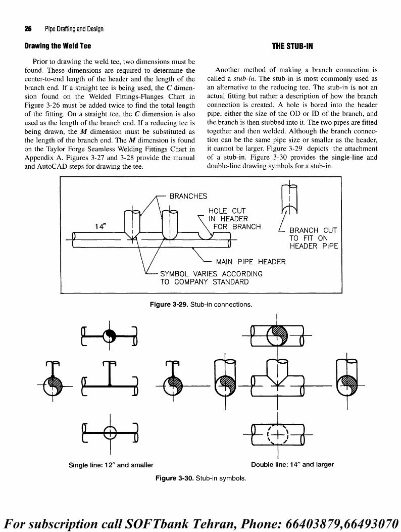
Drawing the Weld Tee THE STUB-IN
Prior to drawing the weld tee, two dimensions must befound. These dimensions are required to determine the Another method of making a branch connection iscenter-to-end length of the header and the length of the called a stub-in. The stub-in is most commonly used asbranch end. If a straight tee is being used, the C dimen- an alternative to the reducing tee. The stub-in is not ansion found on the Welded Fittings-Flanges Chart in actual fitting but rather a description of how the branchFigure 3-26 must be added twice to find the total length connection is created. A hole is bored into the headerof the fitting. On a straight tee, the C dimension is also pipe, either the size of the OD or ID of the branch, andused as the length of the branch end. If a reducing tee is the branch is then stubbed into it. The two pipes are fittedbeing drawn, the M dimension must be substituted as together and then welded. Although the branch connec-the length of the branch end. The M dimension is found tion can be the same pipe size or smaller as the header,on the Taylor Forge Seamless Welding Fittings Chart in it cannot be larger. Figure 3-29 depicts the attachmentAppendix A. Figures 3-27 and 3-28 provide the manual of a stub-in. Figure 3-30 provides the single-line andand AutoCAD steps for drawing the tee. double-line drawing symbols for a stub-in.
Figure 3-29. Stub-in connections.
Figure 3-30. Stub-in symbols.
For subscription call SOFTbank Tehran, Phone: 66403879,66493070

Pipe Fittings 27
How close stub-ins are made is an important consider- drawing representations of reinforcing pads andation. A general rule is to allow a minimum of 3" between saddles.welds. This means a minimum of 3" should be allowed • O-lets. Purchased fittings, o-lets have one endbetween the outsides of branches made from a common shaped to the contour of the header and the other endheader, and a header should be attached no closer than 3" to manufactured to accept the type of end connectionsa fitting. Figure 3-31 provides the minimum measurements being used on the branch. Weldolets are manufac-allowed between branches and fittings on an 18" header. tured for butt-weld fittings. Sockolets are made for
socket-weld fittings. And threadolets are availableStub-in Reinforcements for screwed fittings. Figure 3-33 shows a typical
threadolet. Figure 3-34 gives drawing symbols forEven though the use of the stub-in is limited by the weldolets, sockolets, and threadolets.
pressure, temperature, and commodity within a pipe, itsuse is becoming increasingly more popular. Its chief Other o-lets are manufactured to be used to make con-advantage over the tee is cost. Not only can the cost of nections at angles other than 90°. Figure 3-35 shows apurchasing a fitting be avoided, but the stub-in requires latrolet and the elbolet.only one weld; whereas, the tee requires three. Wheninternal conditions such as pressure or temperature of the COUPLINGcommodity or external forces such as vibrations or pulsa-tions are placed on a stub-in, special reinforcement mav A *u * cr^- j. i u ur , , , J Another type of fitting used to make branch connectionsbe necessary to prevent the branch from separating from • ., r T T , • •, f .. „ u, , , * F . _ . , . ,. ,7 is the coupling. Used primarily for connecting small-borethe header. Three remforcmg alternat.ves are listed below. scr£wed and socket_weld pipe to large.bore pipe headers,
• Reinforcing pad. Resembling a metal washer that the coupling is also used extensively where instrument, 0 , Qr, K . . f . ., . f ,, connections are required. There are two common methodshas been bent to conform to the curvature of the M
•_Q t, • f , • - .f . T , . used to make branch connections with couplings:pipe, the reinforcing pad is a ring cut from steel plate F 6
that has a hole in the center equal to the diameter of 1. The coupling rests on the external surface of the pipethe branch connection. It is slipped onto the branch header and is welded from the outside.pipe then welded to both branch and header. 2. A hole is bored into the pipe header large enough to
• Welding saddle. A purchased reinforcing pad, the accept the OD of the coupling. The coupling iswelding saddle has a short neck designed to give inserted into the hole and is then welded. Figure 3-36additional support to the branch. Figure 3-32 shows shows the coupling in use.
Figure 3-31. Welding minimums for stub-ins.
For subscription call SOFTbank Tehran, Phone: 66403879,66493070

28 Pipe Drafting and Design
Figure 3-32. Reinforcing pads and saddles.
Figure 3-33. Threadolet.
REDUCERS
When the piping designer wants to reduce the diameterof a straight run of pipe, a reducing fitting must be used.Appropriately named, the reducer is available in twostyles as shown in Figure 3-37.
Concentric—having a common centerline.Eccentric—having offset centerlines.
The concentric reducer maintains the same centerlineat both the large and small ends of the fitting.
The eccentric reducer has offset centerlines that willmaintain a flat side on the top or the bottom of the fitting,depending on how the fitting is rolled prior to welding.
Figure 3-35. Latrolet and elbolet.
The eccentric reducer is used in piperacks to maintain aconstant bottom of pipe (BOP). Because pipe supportswithin a piperack are of the same elevation, a pipe musthave a consistent bottom of pipe elevation so it can rest oneach support throughout its entire length. Using a concen-tric reducer in a piperack would not permit the smalldiameter end of the pipe run to rest on a pipe support.
Eccentric reducers are also used on pump suction noz-zles to keep entrained air from entering the pump. Bykeeping a flat on top (FOT) surface, vapor pockets can beeliminated. Figure 3-38 shows the centerlines of theeccentric reducer in its FOT and FOB orientations.
It is important that a designer not forget to include thedimensional difference between the two centerlines of an
For subscription call SOFTbank Tehran, Phone: 66403879,66493070

Pipe Fittings 29
Figure 3-36. Couplings as branches.
eccentric reducer when calculating the elevations of pipein a piperack. The formula for calculating this difference is
Offset = Large ID - small ID / 2
A quicker, though less accurate method, is to take one-half the difference between the two outside diameters.
Drafting Symbols for the Concentric and EccentricReducer
The orthographic views for the concentric and eccen-tric reducers are shown in Figure 3-39. No matter the sizeof the reducer, it is always drawn as a double-line symbol.Notice the callouts that must be included with the eccen-tric reducer. The large end is always listed first, no matterthe direction of flow, and the flat side must be indicated.
Figure 3-37. Eccentric and concentric reducer.
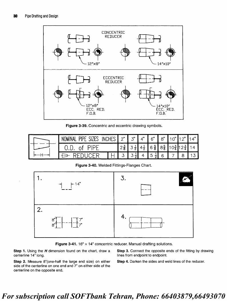
Drawing the Reducers
Prior to drawing the reducer, the length of the fittingmust be found on the Welded Fittings-Flanges Chart (seeFigure 3-40). The H dimension will provide the end-to-end length for either the concentric or eccentric reducer.Always use the H dimension of the large end to determinethe fitting length.
Figures 3-41 and 3-42 provide the manual andAutoCAD steps for drawing the reducer.
Figure 3-38. Eccentric reducers.
For subscription call SOFTbank Tehran, Phone: 66403879,66493070
30 Pipe Drafting and Design
Figure 3-39. Concentric and eccentric drawing symbols.
Figure 3-40. Welded Fittings-Flanges Chart.
Figure 3-41.16" x 14" concentric reducer. Manual drafting solutions.
Step 1. Using the H dimension found on the chart, draw a Step 3. Connect the opposite ends of the fitting by drawingcenterline 14" long. lines from endpoint to endpoint.
Step 2. Measure 8"(one-half the large end size) on either Step 4. Darken the sides and weld lines of the reducer,side of the centerline on one end and 7" on either side of thecenterline on the opposite end.
For subscription call SOFTbank Tehran, Phone: 66403879,66493070

Pipe Fittings 31
Figure 3-42. 10" x 8" eccentric reducer (FOB). AutoCAD commands.
Drawing set-up. Set LINETYPE to Continuous. Step 3. Draw a PLINE from 10,20 to 17,18. TRIM the top of
Set LIMITS: lower left-0,0; upper right-20,20. the ri9ht line to comPlete the symboL
ZOOM, All. ZOOM, Extents.
Step 1. Draw a vertical PLINE with a width of .56" (9/16") for f teP 4' » necessary draw a PLINE having a width of .0175"full scale or .0175" for %" =1 '-0" scale, 10" tall from 10,10. from ** MIDP°mt of each vertical line outward to represent
pipe. Place note as required.Step 2. OFFSET this line 7" to the right. Draw a PLINE 7" longfrom 10,10 to 17,10 connecting the bottoms of the two lines.
WELD CAP Depending on the given situation, fittings will either bewelded to each other or separated by lengths of pipe.
The last weld fitting we will discuss is the weld cap. It Welding one fitting directly to another is called fitting-is used to seal an open end of pipe. When dimensioning make-up (see the examples in Figure 3-44).the positional location of a weld cap on a drawing, indi- Most situations involving the erection of the pipingcate only the length of the run of pipe. The cap will be system require the designer to use pipe of various lengthswelded to the end and need not be included in the length between the fittings. In these cases, pipe is cut to thedimension of the run of pipe. required length and the ends are beveled in preparation
The weld cap is another fitting that is drawn as a dou- for welding to the fittings. When fittings are not assem-ble-line symbol for all sizes of pipe. bled as fitting make-up and are separated by a piece of
The length of the fitting is found on the Taylor Forge pipe? most companies stipulate the pipe must be at leastSeamless Welding Fittings Chart in Appendix A. one pipe diameter (nominal size) in length with a 3" mini-
When representing the cap on a drawing, use an ellipse mum spacing for pipe 6" and smaller. By maintaining thisto construct the round end of the fitting. Figure 3-43 minimum spacing between welds, a pipe can conve-shows the single-line and double-line drawing symbols niently be cut> beveied, and welded without interferencefor a weld cap. Notice the weld dot on the single line (see Rgure 3.45) The y minimum spacing is a standard
symbol is drawn as a half circle only. used throughout the piping industry and win be applied to
the drawing exercises and projects in this text.USE OF FITTINGS Welds may seem insignificant to the designer, but, it
goes without saying, a piping facility could not be builtThus far, we have discussed each fitting individually. without them. Remember, all welds must be shown on
We will now look at how each fitting relates to other fit- drawings. Use weld dots on single-line pipe symbols andtings when used in the design of various piping systems. weld lines on double-line pipe symbols.
For subscription call SOFTbank Tehran, Phone: 66403879,66493070

32 Pipe Drafting and Design
Dimensioning Of Fitting Make-Up • Pipe should be dimensioned from center of fitting tocenter of fitting, or
The next step in the drawing of pipe is the calculation . Pipe should be dimensioned from center of fitting toand placement of dimensions. At the present time, we the end of pipeare only concerned with butt-weld fittings. The generalrules-of-thumb for placing dimensions on a drawing are Figure 3-46 provides some examples for placingas follows: dimensions on drawings.
Figure 3-43. Weld cap drawing symbols.
Figure 3-44. Fitting make-up.
Figure 3-45. Minimum pipe lengths.
For subscription call SOFTbank Tehran, Phone: 66403879,66493070

Pipe Fittings 33
SCREWED AND SOCKET-WELD FITTINGS
Screwed and socket-weld fittings perform the samebasic functions as butt-weld fittings. There are, however,a few differences that must be examined. Screwed andsocket-weld fittings are normally reserved for installa-tions using fittings 3" and smaller. Screwed and socket-weld fittings are also available in cast iron, malleableiron, or forged steel. Cast iron and malleable iron fittingsare typically used on low pressure and temperature linessuch as air, water, or condensate.
Lines containing high pressure and temperaturecommodities, which are subject to movement andvibration, require fittings made of forged steel. Forgedsteel screwed and socket-weld fittings are manufac-tured in two pressure classes—3000# and 6000#.Dimensional charts for screwed and socket-weld fit-tings are provided in Appendix A. These dimensioningcharts supply measurements for 3000# and 6000# fit-tings. Figures 3-47 and 3-48 provide a sample of thedimension charts for screwed and socket-weld fittingsfound in Appendix A.
Most screwed fittings are manufactured with internal,female threads per American Standard and API threadguidelines (see Figure 3-49). Some fittings, such as plugsand swages, however, are manufactured with externalthreads.
The socket-weld fitting is replacing the screwed fit-ting as the choice of many fabricators because it offersgreater strength. Even though screwed fittings can beseal welded if necessary, strength of the fitting isdecreased when the threads are cut during the manufac-turing process. Socket-weld fittings can be easily fittedand welded without the need of special clamps or tack-welds, which are often required to hold a butt-weldfitting in place before the final weld is made (seeFigure 3-50).
Like butt-weld fittings, screwed and socket-weld fit-tings are used to make similar configurations in a pipingsystem. Screwed and socket-weld fittings differ in sizeand shape, but they achieve the same purpose as the butt-weld fittings. Figure 3-51 provides examples of somescrewed and socket-weld fittings.
Screwed and socket-weld fittings are drawn withsquare corners using short hash marks to represent theends of the fitting (see Figure 3-52).
Unions
The union, shown in Figure 3-53, is a fitting placedwithin a piping configuration that will allow the assembly tobe disassembled for inspection, repair, or replacement.Manufactured for screwed and socket-weld applications, theunion is represented on drawings as shown in Figure 3-54.
Unions should be positioned in locations that willfacilitate the easy removal of critical pieces of equipment.Figure 3-55 shows how unions are placed in a configura-tion to allow easy removal of the valves.
Plug
The plug, like a cap, is designed to close off the end ofa run of pipe. Plugs are manufactured for screwed fittingswith male threads and are screwed into the end of a pipeto create a seal. Figure 3-56 shows the drawing symbolsfor the plug.
Coupling
Although this fitting is used in butt-welding applica-tions as a branch connection, its primary use is to connectlengths of screwed and socket-weld pipe together. Someclients may stipulate, however, that all socket-weld pipemust be connected with a butt weld, rather than a coupling.
PIPE NIPPLES
By design, screwed and socket-weld fittings cannot beassembled by placing one fitting directly in contact withanother fitting. Screwed fittings are manufactured withthreads on the inside of the fitting, and socket-weld fit-tings have an internal socket that prevents fitting makeupassembly. To facilitate the assembly of screwed andsocket-weld fittings, small lengths of pipe called pipe nip-ples are used between fittings. Pipe nipples can vary inlength depending upon the distance required to fabricatethe pipe configuration. A close nipple is one that providesthe minimum length of pipe between fittings. Remember,screwed and socket-weld fittings have a certain amount oflost pipe due to thread engagement and socket depth.Therefore, each size pipe has a different minimum lengthfor the dimension of a close nipple.
Many companies will use 3" as the standard minimumfor pipe nipples. This length will accommodate theamount of pipe lost inside the fitting on each end as wellas provide sufficient wrench clearance during assemblyfor the larger screwed and socket-weld pipe sizes.
For subscription call SOFTbank Tehran, Phone: 66403879,66493070

34 Pipe Drafting and Design
Figure 3-46. Placement of dimensions.
Figure 3-47. Screwed fittings dimensioning chart.
For subscription call SOFTbank Tehran, Phone: 66403879,66493070

Pipe Fittings 35
Figure 3-48. Socket-weld fittings dimensioning chart.
Figure 3-49. Internal and external threads.
For subscription call SOFTbank Tehran, Phone: 66403879,66493070

36 Pipe Drafting and Design
Figure 3-50. Socket-weld fittings.
Figure 3-51. Screwed and socket-weld fittings.
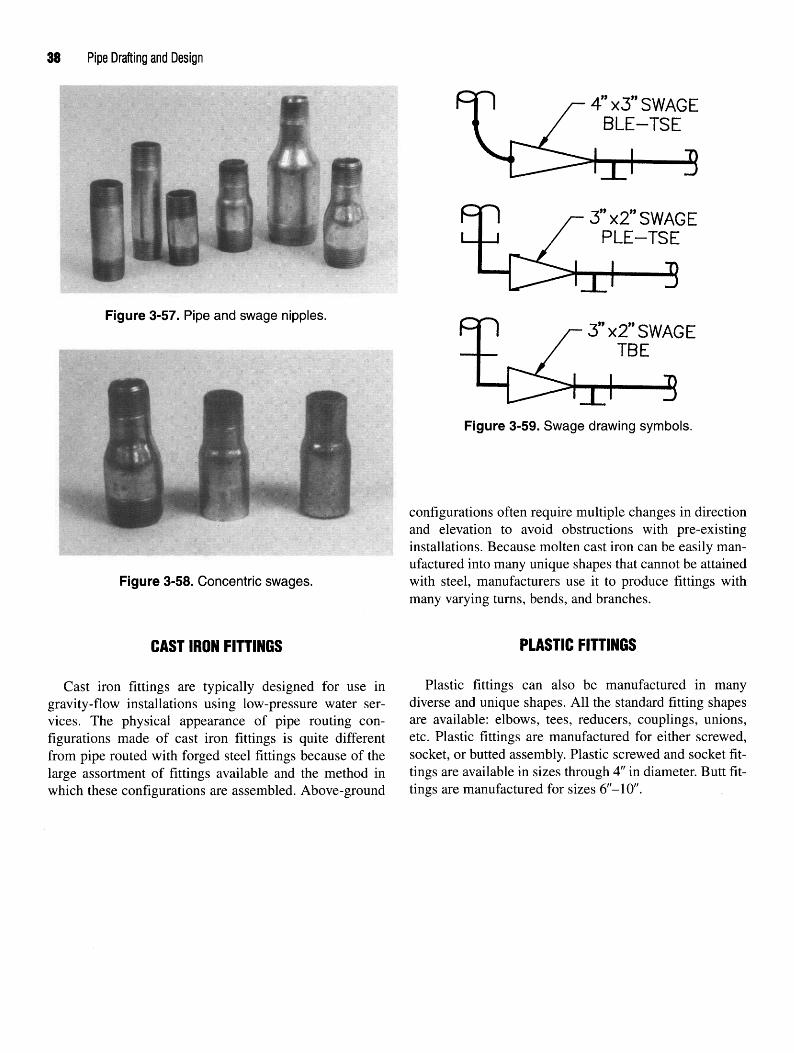
Swage
One exception to the standard 3" minimum rule is theswage nipple. Swages are functionally similar to reduc-ers, but are specifically designed for screwed and socket-weld pipe. Screwed swages have male (external) threadsand can be connected to other screwed fittings without theuse of a pipe nipple. They are used to make reductions inthe line size on a straight run of pipe. Swages, like reduc-ers, are available in either a concentric or eccentric shape.Figure 3-57 shows varying lengths and sizes of screwedpipe and swage nipples.
Figure 3-52. Screwed and socket-welddrawing symbols.
For subscription call SOFTbank Tehran, Phone: 66403879,66493070

Pipe Fittings 37
Figure 3-53. Union
Figure 3-54. Union drawingsymbols.
Swages are unique in that they can be used in screwed,socket-weld, or butt-weld configurations. When used inthese configurations, swages will have different end prep-arations. Screwed swages will have thread ends (TE),socket-weld swages plain ends (PE), and butt-weldswages have beveled ends (BE). Because socket-weldswages are inserted into mating fittings, many compa-nies allow the substitution of beveled-end swages. Dualpurpose fittings like these will make the job of the pur-chasing group much easier. Swages are also manufacturedwith different preparations on the two ends. When speci-fying a swage, use the following abbreviations:
BBE—bevel both ends
TBE—thread both ends
PBE—plain both ends
Figure 3-55. Positioning of unions.
Figure 3-56. Plug drawing symbols.
BLE/TSE—bevel large end/thread small end
PLE/TSE—plain large end/thread small end
Figure 3-58 depicts the concentric swage. Notice theend preparation combinations on the examples.
Figure 3-59 shows the drawing symbols for swages.
FLANGED FITTINGS
Flanged fittings perform functions similar to other fit-tings of the same type. The major difference is theirmethod of connection. The connection joint for flangedfittings is made by bolting two specially designed metalsurfaces together. A gasket to prevent leaks is sandwichedbetween the two surfaces. Flange types will be discussedat great length in the following chapter.
For subscription call SOFTbank Tehran, Phone: 66403879,66493070
38 Pipe Drafting and Design
Figure 3-57. Pipe and swage nipples.
Figure 3-58. Concentric swages.
CAST IRON FITTINGS
Cast iron fittings are typically designed for use ingravity-flow installations using low-pressure water ser-vices. The physical appearance of pipe routing con-figurations made of cast iron fittings is quite differentfrom pipe routed with forged steel fittings because of thelarge assortment of fittings available and the method inwhich these configurations are assembled. Above-ground
Figure 3-59. Swage drawing symbols.
configurations often require multiple changes in directionand elevation to avoid obstructions with pre-existinginstallations. Because molten cast iron can be easily man-ufactured into many unique shapes that cannot be attainedwith steel, manufacturers use it to produce fittings withmany varying turns, bends, and branches.
PLASTIC FITTINGS
Plastic fittings can also be manufactured in manydiverse and unique shapes. All the standard fitting shapesare available: elbows, tees, reducers, couplings, unions,etc. Plastic fittings are manufactured for either screwed,socket, or butted assembly. Plastic screwed and socket fit-tings are available in sizes through 4" in diameter. Butt fit-tings are manufactured for sizes 6"-10".

Pipe Fittings 39
CHAPTER 3 REVIEW QUIZ
1. Typically, pipe smaller than 3" in diameter is manufactured as having orend connections.
2. What is the most common fitting used?
3. What are the four classifications of elbows?
4. What is the formula for calculating the center-to-end dimension for LR and SR elbows?
LR=
SR=
5. Describe a mitered elbow.
6. When configuring tee connections, what is the main run of pipe called?
7. Name the two types of tees.
8. What are some alternate methods to a tee fitting when fabricating branch connections?
9. Which fitting is used to make a reduction in the line size of a run of pipe?
10. Name the two types of reducers.
11. Define fitting make-up.
12. What are the two pressure classifications for screwed and socket-weld fittings?
13. What type of fittings must be bolted together?
14. What is the typical installation service for cast iron pipe?
15. Name the three types of plastic fitting end types manufactured.

40 Pipe Drafting and Design
EXERCISE INFORMATION • Place a base point on one end of each fitting usingMIDpoint, ENDpoint, or CENter OSNAP options.
The fittings depicted in Figure 3-60 will be used to complete . jn the "Block Definition" dialog box check thethe exercises in Chapters 3,4, 5, and 10. To complete the exer- Create icon from block geometry radio button,cises, draw the symbols below using the following guidelines. • SAVE the file as "ELBOWS.dwg".
• Start from scratch and draw all symbols full scale.• Draw symbols with a PLINE having a width of .56" After the symbols have been created and the drawing
(y]6") for single line symbols and a 0" width for double saved' start the exercise drawing and use AutoCADline fittings. Symbols requiring a full circular shape must Design Center to open the file ELBOWS.dwg. Insert thebe drawn with the PLINE command ARC option. These required symbols into the appropriate locations.arcs can only be drawn with a 359° circumference. NOTE: The pipe break symbol is created with ellipses.
• Create weld dots with a 1.75" diameter DONUT. The maJor axis of each ellipse is equal to one-half of the• Block each symbol individually using the block P1?6'8 OD- TRIM or BREAK an ellipse to create the
name indicated. (DO NOT include text with the elliptical arc on the pipe break as necessary.blocked symbol.)
Figure 3-60. AutoCAD drawing symbols and File names.

Pipe Fittings 41
CHAPTER 3 DRAW
ING EXERCISES

42 Pipe Drafting and Design

Pipe Fittings 43

44 Pipe Drafting and Design

Pipe Fittings 45

46 Pipe Drafting and Design

Pipe Fittings 47

Flange Basics
The flange is a ring-shaped device designed to be usedas an alternative to welding or threading various pipingsystem components used throughout the piping system.Flanged connections are used as an alternative to weldingbecause they can be easily disassembled for shipping,routine inspection, maintenance, or replacement. Flangedconnections are preferred over threaded connectionsbecause threading large bore pipe is not an economical orreliable operation. The flange is an important componentof any piping system.
Flanges are primarily used where a connecting or dis-mantling joint is needed. These joints may include join-ing pipe to fittings, valves, equipment, or any otherintegral component within the piping system.
To erect the piping system, every piece of mechanicalequipment is manufactured with at least one outlet calleda nozzle. The nozzle is the point where, via the flange, thepiping system is connected to the equipment. From thisflange, the piping system is begun. Figure 4-1 shows howa nozzle and flange are used to connect the piping systemto a piece of equipment.
Figure 4-1. Nozzle and flange.
RATING FLANGES
Rating, as applied to flanges, may best be defined asthe maximum pressure allowed by the pressure pipingcode for the specific temperature at which the flange willbe operating. Flanges and nozzles are sized according topressure ratings established by the American NationalStandards Institute (ANSI). These pressure ratings,
sometimes called pound ratings, are divided into sevencategories for forged steel flanges. They are 150#, 300#,400#, 600#, 900#, 1500#, and 2500#. Cast iron flangeshave pound ratings of 25#, 125#, 250#, and 800#.
Pound ratings, when combined with the temperature ofthe commodity within the pipe, are used to select theappropriate size, rating, and type of flange. This pressure/temperature relationship will allow any given flange to beused in a number of different applications. For example, a150# forged steel flange is rated to perform at 150# PSIGat 500°F. If the temperature were decreased to 100°F, thissame flange could be used for 275# PSIG. However,if the temperature were increased to 750°F, the flangecould only be used for 100# PSIG. As you can see, thepressure/temperature relationship is important. Whentemperature decreases the allowable pressure increases,and vice versa. Pound ratings are also used to establishthe outside diameter and thickness of a flange. Typicallyas pound ratings increase, so will the flange's diameterand thickness.
FLANGE FACINGS
The mating surface of a flange, nozzle, or valve iscalled the face. The face is usually machined to create asmooth surface. This smooth surface will help assure aleak-proof seal when two flanges are bolted together witha gasket sandwiched between.
Although numerous types of flange faces are pro-duced, we will focus only on the following three:
• flat face• raised face• ring-type joint
Flat face
As the name implies, flanges with flat faces are thosethat have a flat, level connecting surface (see Figure 4-2).Forged steel flanges with a flat face flange are commonly
48

Flange Basics 49
Figure 4-2. Flat face.
found in 150# and 300# ratings. Their principal use is tomake connections with 125# and 250# cast iron flanges,respectively. Attaching steel pipe to the cast iron flangesfound on some valves and mechanical equipment alwayspresents a problem because of the brittle nature of castiron. Using a flat face flange will assure full surface con-tact, thereby reducing the possibility of cracking thesofter cast iron. Figure 4-3 shows a sectional view of aflange with a flat face.
Raised Face
The most common face type in use, the raised face isavailable in all seven of the aforementioned pound rat-ings. Appropriately named, this flange face has a promi-nent raised surface. With shallow grooves etched into theraised surface, this flange face assures a positive grip withthe gasket. Flanges rated 150# and 300# have a Me" raisedface, while flanges 400# and above have a 1A" raised face(see Figure 4-4). It is important to note most dimension-ing charts, including the ones provided in this text,include the Yi6r raised face thickness in the length dimen-sions for 150# and 300# flanges. However, the 1A" raisedface thickness is not always included in the length dimen-sions for 400# and higher pound ratings. To assureaccurate dimensioning, always determine if the dimen-sioning chart being used includes the 1A" raised facethickness for the larger pound rating flanges. The 1A"raised face thickness must be added to the dimensioningchart measurement to obtain the overall flange length ifthe dimensioning chart indicates it has not been added.Figure 4-5 includes a sectional view of a weld neck flangehaving a raised face.
Figure 4-3. Welding neck flange with flat face.
Figure 4-4. Raised face.
Ring-Type Joint
Also known simply as ring joint, the ring-type jointdoes not use a gasket to form a seal between connectingflanges. Instead a round metallic ring is used that rests ina deep groove cut into the flange face (see Figure 4-6).The donut-shaped ring can be oval or octagonal in design.As the bolts are tightened, the metal ring is compressed,creating a tight seal.
Although it is the most expensive, the ring-type joint isconsidered to be the most efficient flange used in processpiping systems. The ring and groove design actually usesinternal pressures to enhance the sealing capacity of theconnecting flanges. The superiority of this seal can haveits disadvantages, however. When dismantling ring jointconnections, the flanges must be forcibly separated torelease the ring from the groove. In crowded installations,this could cause major problems. Because of this, the ring

50 Pipe Drafting and Design
Figure 4-5. Weld neck flange with raised face
FLANGE TYPES
Flanges have been designed and developed to be usedin a myriad of applications. Each one has its own specialcharacteristics, and should be carefully selected to meetspecific function requirements. The following flangeswill be discussed in this chapter:
• weld neck
• threaded
• socket weld
• slip-on
• lap-joint
Figure 4-6. Ring-type joint. * re ucm§• blind
• orifice
NOTE: A photograph and short description accompa-joint flange is relegated to applications where space for nies each flange as well as symbols to depict the flange asmaintenance and replacement are adequate. it would appear on a drawing. The manual and AutoCAD
Although available for all pound ratings, flanges with techniques for creating the drawing symbols are shownring-type joint faces are normally used in piping systems for the weld neck flange only. The drawing symbols forrated 400# and higher. See Figure 4-7 for the sectional the remaining flanges can be created in a similar fashionview of a flange with a ring-type joint face. with only a few minor alterations.

Weld Neck Flange
The weld neck flange shown in Figure 4-8 is occasion-ally referred to as the "high-hub" flange. It is designed toreduce high-stress concentrations at the base of the flangeby transferring stress to the adjoining pipe. Althoughexpensive, the weld neck flange is the best-designed buttweld flange available because of its inherent structuralvalue and ease of assembly.
Known for its strength and resistance to dishing, theweld neck flange is manufactured with a long taperedhub. The tapered hub is created by the gradual increasein metal thickness from the weld joint to the flangefacing. The symmetrical taper transition is extremely ben-eficial under conditions of repeated bending caused byline expansion, contraction, or other external forces. SeeFigure 4-9, for weld neck flange drawing symbols.
Weld neck flanges are normally used in severe serviceapplications involving high pressures, high temperatures,or sub-zero conditions.
Weld neck flanges are bored to match the ID of theadjoining pipe. In other words, the thinner the wall ofthe pipe, the larger the bore (hole) through the flange. Thethicker the wall of the pipe, the smaller the bore. Becauseof these matching IDs, there is no restriction to the flow.Turbulence and erosion are therefore eliminated.
Drawing the Weld Neck Flange
Prior to constructing the manual and AutoCADsymbols, certain dimensional information must be pro-vided. These dimensions can be found on the welded
Flange Basics 51
fittings-flanges dimensioning chart shown in Figure 4-10.The figure in this chart represents the raised face weldneck flange.
Notice the three dimensions: O, T, and L. The Odimension represents the flange's OD. The T defines theflange's face thickness and the L provides the flange'slength or length-thru-hub dimension. These three dimen-sions are required to construct the drawing symbols ofeach flange.
To find the numerical values for these dimensions,locate the appropriate pound rating section, that is, 150#,300#, etc. Find the proper size pipe in the Nominal PipeSize column. Follow across the chart to determine the O,T, and L dimensions. For our demonstration, we will beusing a 14"-300# raised face weld neck (RFWN) flange.You should find the O, T, and L measurements for thisflange to be 23", 2 i/8", and 5 y8" respectively.
Figure 4-8. Weld neck flange.
Figure 4-9. Weld neck flange drawing symbols.
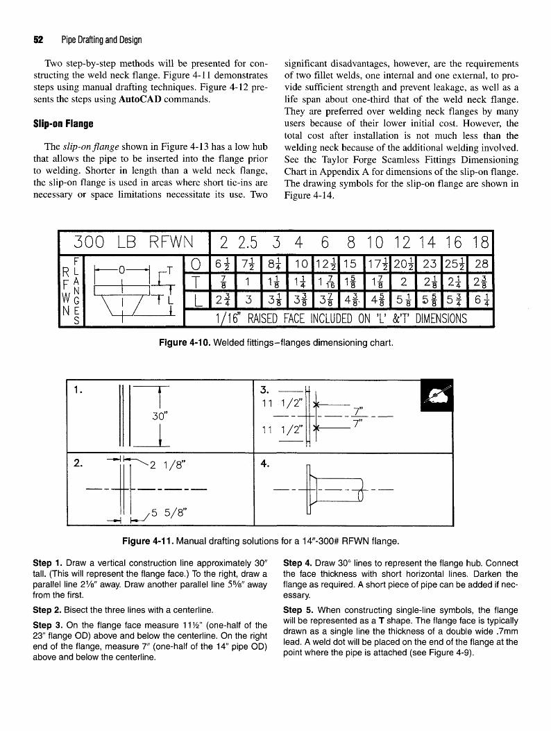
52 Pipe Drafting and Design
Two step-by-step methods will be presented for con- significant disadvantages, however, are the requirementsstructing the weld neck flange. Figure 4-11 demonstrates of two fillet welds, one internal and one external, to pro-steps using manual drafting techniques. Figure 4-12 pre- vide sufficient strength and prevent leakage, as well as asents the steps using AutoCAD commands. life span about one-third that of the weld neck flange.
They are preferred over welding neck flanges by manySlip-On Flange users because of their lower initial cost. However, the
total cost after installation is not much less than theThe slip-on flange shown in Figure 4-13 has a low hub welding neck because of the additional welding involved,
that allows the pipe to be inserted into the flange prior See the Taylor Forge Seamless Fittings Dimensioningto welding. Shorter in length than a weld neck flange, Chart in Appendix A for dimensions of the slip-on flange,the slip-on flange is used in areas where short tie-ins are The drawing symbols for the slip-on flange are shown innecessary or space limitations necessitate its use. Two Figure 4-14.
Figure 4-10. Welded fittings-flanges dimensioning chart.
Figure 4-11. Manual drafting solutions for a 14"-300# RFWN flange.
Step 1. Draw a vertical construction line approximately 30" Step 4. Draw 30° lines to represent the flange hub. Connecttall. (This will represent the flange face.) To the right, draw a the face thickness with short horizontal lines. Darken theparallel line 21/s" away. Draw another parallel line 55/s" away flange as required. A short piece of pipe can be added if nec-from the first. essary.
Step 2. Bisect the three lines with a centerline. Step 5. When constructing single-line symbols, the flangeStep 3. On the flange face measure 11W (one-half of the ™" be ^presented as a T shape. The flange face is typically23" flange OD) above and below the centerline On the right drawn as a Sin9le lme the thlckness of a double Wlde -7mm
end of the flange, measure 7" (one-half of the 14" pipe OD) lead *^ dot wi" be Placed ™ the *nd °f <hem
flan9e at the
above and below the centerline. Point where the P'Pe IS attached <see F|9ure 4'9)'
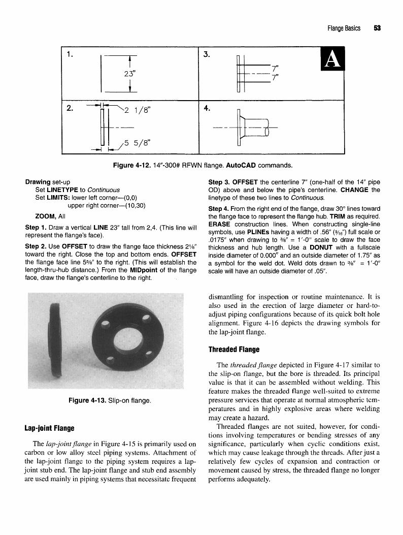
Flange Basics 53
Figure 4-12.14"-300# RFWN flange. AutoCAD commands.
Drawing set-up Step 3. OFFSET the centerline 7" (one-half of the 14" pipeSet LINETYPE to Continuous OD) above and below the pipe's centerline. CHANGE theSet LIMITS: lower left corner—(0,0) linetype of these two lines to Continuous.
upper right corner—(10,30) step 4 From the rjght end Qf the f|ange> draw 3Qo nnes toward
ZOOM, All the flange face to represent the flange hub. TRIM as required.
Step 1. Draw a vertical LINE 23" tall from 2,4. (This line will ER*SE cons'r^o:n 'ines' Wh^ C?n5"ctir!?, s]n9«e-line
represent the flange's face). sVmbols' use PLINEs havin9 a Wldth of '56 <9/16> fu!l scale or
.0175" when drawing to %" = 1'-0" scale to draw the faceStep 2. Use OFFSET to draw the flange face thickness 21/8" thickness and hub length. Use a DONUT with a fullscaletoward the right. Close the top and bottom ends. OFFSET inside diameter of 0.000" and an outside diameter of 1.75" asthe flange face line 5%" to the right. (This will establish the a symbol for the weld dot. Weld dots drawn to %" = 1 '-0"length-thru-hub distance.) From the MIDpoint of the flange scale will have an outside diameter of .05".face, draw the flange's centerline to the right.
Figure 4-13. Slip-on flange.
Lap-joint Flange
The lap-joint flange in Figure 4-15 is primarily used oncarbon or low alloy steel piping systems. Attachment ofthe lap-joint flange to the piping system requires a lap-joint stub end. The lap-joint flange and stub end assemblyare used mainly in piping systems that necessitate frequent
dismantling for inspection or routine maintenance. It isalso used in the erection of large diameter or hard-to-adjust piping configurations because of its quick bolt holealignment. Figure 4-16 depicts the drawing symbols forthe lap-joint flange.
Threaded Flange
The threaded flange depicted in Figure 4-17 similar tothe slip-on flange, but the bore is threaded. Its principalvalue is that it can be assembled without welding. Thisfeature makes the threaded flange well-suited to extremepressure services that operate at normal atmospheric tem-peratures and in highly explosive areas where weldingmay create a hazard.
Threaded flanges are not suited, however, for condi-tions involving temperatures or bending stresses of anysignificance, particularly when cyclic conditions exist,which may cause leakage through the threads. After just arelatively few cycles of expansion and contraction ormovement caused by stress, the threaded flange no longerperforms adequately.

54 Pipe Drafting and Design
Figure 4-14. Slip-on flange drawing symbols.
for use on small diameter W through 4") high-pressurepiping systems. Like socket weld fittings, pipe is insertedinto the socket then welded. An internal weld is oftenemployed for added strength. By grinding the internalweld smooth, turbulence and flow restriction are kept to aminimum. The single-line drawing symbol for the socket-weld flange is shown in Figure 4-20.
Reducing Flange
Like the reducer fitting, the reducing flange in Figure4-21 is used to make a reduction in the diameter ofthe pipe. A reducing flange is most frequently used in
Figure 4-15. Lap-joint flange. installations with limited space. Crowded situations maynecessitate the use of the reducing flange because it has a
A seal weld is sometimes applied around the threaded shorter overa11 len§th when compared to a weld neckjoint to reduce the possibility of leakage. This technique, flan§e and reducer-fitting configuration. Be advised how-however, cannot be considered as entirely satisfactory nor ever> the flow should travel from the smaller size to theis it always possible. Figure 4-18 represents the single- lar§er- If the flow were reversed, severe turbulence couldline threaded flange drawing symbol. develop.
Callouts are placed on drawings to describe the reduc-Socket Weld Flange m§ flange in the same manner as those used on the
reducer fitting: large end first, small end second. OneThe socket weld flange shown in Figure 4-19 is also additional note is needed, however. The pound rating and
similar to the slip-on flange. It was originally developed flange type is included in the callout.
Figure 4-16. Lap-joint flange drawing symbols.

Flange Basics 55
Figure 4-17. Threaded flange.
Figure 4-20. Single-line socket-weld drawing symbol.
Figure 4-18. Single-line threaded flange drawingsymbol.
Figure 4-21. Reducing flange.
Figure 4-19. Socket weld flange.
The reducing flange maintains all the dimensionalcharacteristics of the larger end size. One exception how-ever is the internal bore. The internal bore is manufac-tured to match that of the smaller pipe size. Figure 4-22shows a 12" x 6"-300# raised face slip-on flange. Noticethe use of abbreviations to keep the size of the callout to aminimum.
Reducing flanges are manufactured as weld neck, slip-on, or threaded flange types.
Figure 4-22. Reducing flange drawing symbol withcallout.
Blind Flange
The blind flange depicted in Figure 4-23 serves a func-tion similar to that of a plug or cap. It is used to terminatethe end of a piping system. The blind flange is basically aflange that does not have a hub or a bored center. Blindflanges have the face thickness of a flange, a matching

56 Pipe Drafting and Design
face type, and similar bolting pattern. Blind flanges can recorded is known as a meter run. Figure 4-26 shows thealso be used to seal a nozzle opening on a pressure vessel. orifice flange union assembly installed in a meter run.Because it is bolted, the blind flange provides easy access The orifice plate, which is not typically furnished withto the interior of a vessel or pipe, unlike a cap that is the orifice union assembly package, looks similar to awelded. Figure 4-24 represents the drawing symbol for large ring washer with a handle attached. When fullythe blind flange. assembled, the orifice plate is sandwiched between the
orifice flanges. Valve taps are inserted into pressure holesOrifice Flanoe mat a^ow f°r me attachment of field monitoring equip-
ment so accurate measurements can be recorded._ , ,. , , .„ ._. Orifice flanges can be either weld neck, slip-on, orOf the flanges discussed, the orifice flange (Figure ^, , , ,™ , , , , iU , , .,- „
A nf. . , , , „ r c . threaded. The weld neck and threaded orifice flanges are4-25) is the only one that actually performs a function. f . , . orkru, ,, , .. TT^, ' . - , . _ _ . , ,, manufactured in 300# and larger pound ratings. However,The function of the orifice flange is to measure the rate of ., v •*- f\ • i -i ui ™n.u • j, , , . . the slip-on orifice flange is only available as a 300# raisedthe flow of the commodity through the piping system. ,. „ . , J .^ .~ „ . , , , face flange. The single-line and double-line drawing sym-Onfice flanges are easy to recognize because they have a u , ^ T. .^ ^ , • ^- A ̂, , , . „ , , , / c ? , ,• ! bols for the orifice flange are shown in Figure 4-27.hole drilled through the face of the flange perpendicularto the pipe. They also have an additional set of boltscalled jack screws. These screws are used to help separatethe flanges so inspection and/or replacement of the orificeplate can be performed. The orifice flange is a singlecomponent of the orifice flange union assembly. The ori-fice flange union is composed of two orifice flanges, anorifice plate, bolts, nuts, jack screws, and two gaskets.
The orifice flange union is used to measure, or meter,the amount of pressure drop through the orifice plate. Thelength of pipe within the piping system where orificeflanges are installed and where these measurements are
Figure 4-25. Orifice flange.
Figure 4-23. Blind flange.
Single line: 12" and smaller Double line: 14" and larger Flgure 4.26- Orifice flange union assembly. Courtesy ofFigure 4-24. Blind flange drawing symbols. Nisseki Chemical Texas Inc., Bayport, Texas.

Flange Basics 57
Figure 4-27. Orifice flange drawing symbols.
BOLTS Formula: 360° / # of holes = angular location
To complete any flanged assembly, two additional Example: 360°/8 (holes) = 45°items are required: bolts and gaskets. Bolts obviouslyhold mating flanges, nozzles, or valves together. The Using this formula shows holes on an eight-hole flangepressure rating of a flange will determine the size, spac- to be spaced 45° apart. By straddling the centerline, holesing, and number of bolts required. As the nominal pipe will be positioned 221/2° on each side of the centerlinesize and pressure ratings change so will the diameter, (see Figure 4-28).spacing, and number of bolts. Bolts are available in two types, machine or stud.
Flanges are designed to match the bolt circle and bolt Machine bolts have a "head" on one end and threads onhole dimensions of other flanges that are of the same the other. Stud bolts have threads throughout their entirediameter and pressure rating. Bolt hole arrangements may length and require the use of two nuts. Stud bolts are theseem inconsequential, but, when one considers the fact most commonly used type and are available in twothat components of a piping system may be fabricated in grades, A-193-B7 and A-193-B16. B7 grade bolts areone country then shipped to another country for assembly, used for temperatures to 1,000°F. B16 bolts are usedbolt alignments become increasingly important. It is criti- when temperatures exceed 1,000°F (see Figure 4-29).cal that drawings convey the exact orientation of flanges tothe fabricator. Otherwise, bolt holes may not align prop-erly. ANSI standards require all flanges straddle either thehorizontal, vertical, or north-south centerlines of pipe and uAoKtloequipment, unless otherwise noted on a drawing.
To assure that bolt holes on flanges, nozzles, or valves The primary purpose of any flanged assembly is toalign properly, holes are equally spaced around the connect piping systems in such a manner as to produce aflange. One column on the Taylor Forge Forged Steel leak-free environment. Hazardous and combustible mate-Flanges Dimensioning Chart found in Appendix A indi- rials and extreme pressures and temperatures require thecates the number and diameter of the bolt holes on utmost in safety precaution. Creating a leak-proof sealflanges. Notice bolts are found in quantities of four, that between two connecting metal surfaces in an industrialis, 4, 8, 12, 16, etc. The following formula makes bolt setting is almost impossible. Therefore, gaskets perform ahole location and alignment quick and simple. vital function in plant safety.

58 Pipe Drafting and Design
Figure 4-28. Bolt hole spacing.
Using a gasket material softer than two adjoining A gasket's thickness must be accounted for whenflanges is an excellent way to eliminate the possibility of dimensioning the piping system. The typical gasket has aa fluid escape. Gaskets can be made of materials such as thickness of V%" (3.175mm). At every occurrence of aasbestos, rubber, neoprene, Teflon, lead, or copper. When flange bolting to a nozzle, two flanges joining onebolts are tightened and flange faces are drawn together, another, two valves joining one another, or a flange con-the gasket material will conform to any imperfections in necting to a valve, a gasket thickness must be added to thethe flange faces to create a uniform seal. length of the pipe components. Figures 4-34 and 4-35
Figure 4-30 demonstrates the three types of gaskets show that a flat-ring gasket does occupy space. Thoughthat can be found in piping systems. They are full face, it's only V%" thick, a gasket cannot be ignored,flat ring, and metal ring. Full face gaskets (Figure 4-31) Figure 4-36 depicts the gap between ring-type jointare used on flat face flanges. Flat ring gaskets (Figure flanges. The ring-type joint section of the Welded4-32) are used on raised face flanges. Metal rings Fittings-Flanges Dimensioning Chart, gives the gap mea-(Figure 4-33) are used on ring-type joint flanges. surement as the G dimension. This dimension will vary
Figure 4-29. Stud and machine bolts. Figure 4-30. Gaskets. Courtesy of Flexitallic, Inc.

Flange Basics 59
Figure 4-31. Full face gaskets.Figure 4-34. Flat ring gasket and flange. Courtesy ofFlexitallic, Inc.
Figure 4-32. Flat ring gaskets. Courtesy of Flexitallic, Inc
Figure 4-35. Flat ring gaskets between flanges. Courtesyof Flexitallic, Inc.
Figure 4-33. Metal rings for ring-type joint flanges.Courtesy of Flexitallic, Inc. Figure 4-36. Ring-type joint gap spacing.

60 Pipe Drafting and Design
depending on the size and pound rating of the flange. This dimensioning of the piping configuration. Tick marks areis an important consideration to keep in mind when drawn approximately 1A" long and are placed on pipingdimensioning piping runs that have ring-type joint drawings near the location where a gasket or ring is to beconnections. installed. Figure 4-37 depicts two tick marks, one on each
For each instance of a gasket or ring, gap spacing end of a valve, that have been included in the total dimen-must be reflected in the dimensions shown on a piping sion between the faces of the two flanges. The lOVfc"drawing. Tick marks are used to indicate each location dimension would be the sum total of one valve and twowhere a gasket or ring gap has been included in the gaskets.
Figure 4-37. Dimensioning gaskets.

Flange Basics 61
CHAPTER 4 REVIEW QUIZ
1. Name the seven forged steel flange pound ratings.
2. Name the four pressure classes for cast iron flanges.
3. What are the three flange facings discussed in this chapter?
4. What is the thickness of the raised face on a 600# raised-face flange?
5. Briefly describe five types of flanges depicted in this chapter.
6. Give O, T, and L dimensions of the following flanges.
SIZE/RATING O T L
4"— 150#R.F.W.N.
6"—300# R.F.W.N.
10"—400#R.F.W.N. :
16"—600# R.F.W.N.
8"—600# R.F.W.N.

62 Pipe Drafting and Design
7. What is the purpose of an orifice flange union?
8. Name the two types of bolts used to assemble flanges.
9. According to ANSI standards, which centerlines should flanges straddle on pipe and equipment?
10. List four materials used to manufacture gaskets.

Flange Basics 63
EXERCISE INFORMATION • Create weld dots with a 1.75" diameter DONUT.• Block each symbol individually using the block
The fittings depicted in Figure 4-38 will be used to name indicated. (DO NOT include text with thecomplete the exercises in Chapters 4, 5, and 10. To com- blocked symbol.)plete the exercises draw the symbols below using the fol- * Place a base point on one end of each fitting usinglowing guidelines. MIDpoint, ENDpoint, or CENter OSNAP options.
• In the "Block Definition" dialog box check the Cre-• Start from scratch and draw all symbols full scale. ate icon from block geometry radio button.• Draw symbols with a PLINE having a width of .56" • SAVE the file as "FLANGES.dwg".
(9/i6") for single line symbols and a 0" width for dou-ble line fittings. Symbols requiring a full circular After the symbols have been created and the drawingshape must be drawn with the PLINE command saved, start the exercise drawing and use AutoCADARC option. These arcs can only be drawn with a Design Center to open the file FLANGES.dwg. Insert the359° circumference. required symbols into the appropriate locations.

64 Pipe Drafting and Design
Figure 4-38. AutoCAD flange drawing and filenames.

Flange Basics 65
CHAPTER 4 DRAWING
EXERCISES

66 Pipe Drafting and Design

Flange Basics 67

68 Pipe Drafting and Design

Valves
WHAT IS A VALVE?*
A valve is a product rarely noticed by the averageperson, yet it plays an important role in the quality ofour lives. Each time you turn on a water faucet, useyour dishwasher, turn on a gas range, or step on theaccelerator in your car you operate a valve. Withoutmodern valve systems there would be no fresh, purewater in your home, no modern appliances, and no gas-oline waiting at the corner service station.
One of the most widely observed, but least recognized,type of valve is the fire hydrant. Fire hydrants are con-nected to municipal water supply systems. They are spe-cialized in that they are underground valves that can beopened and closed from an above-ground location whenneeded in emergency situations.
By definition, a valve is a device that controls the flowof a fluid. But today's valves can control not only theflow, but also the rate, the volume, the pressure, and thedirection of a fluid within a pipe. Valves are not limited tofluids. They can control liquids, gases, vapors, slurries, ordry materials. Valves can turn on or off, regulate, modu-late, or isolate. They can range in size from a fraction ofan inch to as large as 30 feet in diameter and can vary incomplexity from a simple brass valve, available at thelocal hardware store, to a precision-designed, highlysophisticated coolant system control valve made of exoticmetal alloy used in a nuclear reactor. Valves also can con-trol the flow of all types of commodities. From the thin-nest gas to highly corrosive chemicals, from superheatedsteam to toxic gases, from abrasive slurries to radioactivematerials, valves can be designed to service them all.They can handle temperatures from the cryogenic regionto molten metal exceeding 1500°F, and valves can containpressures ranging from severe vacuum to 20,000 poundsper square inch.
The valve is one of the most basic and indispensablecomponents of our modern technological society. As long Figure 5-1. Gate valve. Courtesy of Jenkins Bros.
*"What is a Valve?" Courtesy of VMA (Valve Manufacturers Association).
69

70 Pipe Drafting and Design
as industries continue to devise new reasons to control flow. Gate valves control the commodity flowing throughgases, liquids, and even solids, valve design will continue the pipe with a flat, vertical wedge, or gate, that slides upto meet the demand. or down as the valve's handwheel is turned. As the hand-
wheel is rotated, the wedge will slide through the valve
rrtMMflN WAI Mf TYPFQ b°dy tO bl°ck °r release the flow-bummura VHLVC i irco Designed to be either fully opened or closed, the gate
valve should not be operated in a partially opened/closedValves are manufactured in numerous sizes, body position. A partially opened gate valve will hasten erosion
styles, and pound ratings to meet a wide variety of appli- caused by the commodity within the pipe and will ruin thecation needs. Valves are also manufactured with varying valve seat in a short period of time. Turbulence from thetypes of end preparations that allow them to be readily commodity will also cause the wedge to vibrate creating amated to flanges or pipe of the same size and rating. "chattering" noise when the valve is partially opened.Valve end preparations can be screwed, socket-weld, bev- Figure 5-1 depicts the external and internal views of aeled, or flanged. Flanged valves are manufactured to have typical gate valve.either raised, flat, or ring-type joint faces. As with pipe, fittings, and flanges, valves are repre-
sented by symbols on piping drawings. These symbols areGate Valves developed in such a manner as to describe the valve's
body style, end type, and handwheel orientation. SymbolThe gate valve is the most frequently used valve in pip- sizes are established from dimensions provided in manu-
ing systems. It is a general service valve that is used pri- facturers' catalogs or data sheets. Three dimensions aremarily for on-off, non-throttling applications. When fully crucial when drawing a valve symbol: face-to-face, hand-opened, the gate valve creates minimal obstruction to the wheel height, and handwheel diameter (see Figure 5-2).
Figure 5-2. Flanged valve dimensioning chart.

Valves 71
The length of a valve is represented on most dimen- located the proper distance from the end of the stem andsioning charts as the face-to-face dimension. The face-to- also to determine when interference problems may occur,face dimension is a length that is standard among valve Another important dimension is the diameter of themanufacturers and defines the length of a valve from one flanged faces on flanged valves. When representingend to the other. Also important is the height and diameter flanged valves, the diameter of the valve's flanges mustof a valve's handwheel. These measurements are neces- be drawn to match the size and pound rating of the flangesary to establish operational clearances and worker acces- or nozzle to which it is being bolted. Because most valvesibility around the valve. Of particular importance is the dimensioning charts do not provide this information, avalve's open handwheel height. This dimension defines drafter must refer to the flange dimensioning chart to findthe maximum height of the valve when it is in the full- the proper flange OD measurements,open position. The open handwheel height is measured Valve symbols vary from company to company and cli-from the centerline of the valve body to the tip of the ent to client. It is therefore imperative that a drafter bevalve stem. familiar with the symbols being used on a project before
The valve stem is a threaded rod that connects the work begins on drawings associated with that newvalve's wedge or gate to the handwheel. Valve stems fall project. The symbols shown in this text are typical ofinto one of two categories: rising or nonrising. A rising those found on many piping drawings. They should not bestem is one in which the stem raises and lowers as the considered standard for all applications, however. Thehandwheel is rotated. The handwheel remains in a sta- symbols shown in Figure 5-3 represent screwed, socket-tionary position as the stem passes through it. On valves weld, and flanged gate valves. Notice also the two meth-having a nonrising stem, the handwheel is attached to the ods of representing handwheels.end of the stem and moves up and down with the stem asthe valve is opened or closed. Drawing the Gate Valve
The length of a rising stem must be determined beforethe handwheel is represented on a drawing. When the Figures 5-4 and 5-5 represent the step-by-step proce-valve is fully opened the stem is at its highest point. The dures to draw a 10"-300# RFWN gate valve symbol usingmaximum distance the stem will extend above the hand- manual and AutoCAD methods of construction, respec-wheel is approximately equal to the nominal size of the lively. Symbols depicting other valve styles can be devel-pipe. Knowing the length of the stem allows a piping oped using similar construction methods but with minordesigner to draw the valve symbol with the handwheel changes or alterations.
Figure 5-3. Gate valve drawing symbols.

72 Pipe Drafting and Design
Figure 5-4. Gate valve. Manual drafting solutions.
Step 1. Using the appropriate vendor's catalog, determine Step 4. From the intersection of the diagonal lines, draw athe overall dimensions of a 10"-300# RFWN gate valve, that centerline parallel to the ends of the valve the length of theis, face-to-face (18"), handwheel height (57") and diameter handwheel height (57").(20"), and flange diameter (17%*). step 5 p|ace fl pojnt Qn ,ne center|jne 1(y, down from the
Step 2. Lightly draw a rectangle having the width of the face- end. Draw a line perpendicular to the centerline (10" is equalto-face (18") dimension and the height of the flange diameter to the nominal pipe size).(17y2") Draw two |ines 1%" (flange face thickness) inside the step 6 Measure Qne.ha|f (1(r) Qf ̂ nandwheel-s diameter
two vertical lines. (2cr) Qn ejther sjde Qf the handwnee| centerline. Draw a dou-
Step 3. Draw diagonal lines across the corners of the inside ble width line to represent the thickness of the handwheel.lines. Erase the horizontal lines of the inside lines. Darken B ?> TQ ^ ̂ e handwhee| ^presentation, draw athe lines representing the valve s body. |jne from each end Qf ̂ nandwnee| to the intersectjng diag.
onal lines of the valve body.
Globe Valves within the valve. The design of the globe valve bodyforces the flow of the commodity to change direction
Globe valves are used primarily in situations where within the valve itself. This change in direction createsthrottling of the commodity is required. By simply rotat- substantial pressure drop and turbulence. The globe valveing the handwheel, the rate at which the commodity flows is therefore not recommended when flow resistance andthrough the valve can be adjusted to any desired level. pressure drop are to be avoided. Figure 5-6 depicts theHaving the valve seat parallel to the line of flow is an internal view of a globe valve.important feature of the globe valve. This feature makes Drawing symbols of the globe valve are similar tothe globe valve efficient when throttling commodities as those of the gate valve. Measurements used to draw thewell as yielding minimal disc and seat erosion. This con- valve are found on manufacturers' dimensioning charts,figuration, however, creates a large amount of resistance One noticeable difference is the use of a darkened circle

Valves 73
Figure 5-5. Gate valve. AutoCAD drawing commands.
Drawing set-up Step 4. Set LINETYPE to Center. From the intersection ofSet LINETYPE to Continuous the diagonal lines, draw a vertical LINE the length of theSet LIMITS: lower left corner - (0,0) handwheel, height (@0,57").
upper right corner - (20,20) ZOOM Extents
ZOOM, All- , . „ , . . . . . . . , . . . . Step 5. Place a POINT 10" to the left (one-half of the hand-Step 1. Using the appropriate vendors catalog, determine . ,, .. , , , ._„ . , .. . ,.. . ,,. *j. . . /!„ „;:_.. m-iA/M * i * u * - « whees diameter) and 10" down from the end (distance equalthe dimensions of a 10"-300# RFWN gate valve, that is, face- . .. . , . . . > . .. . . . ,, . ,.* * /..o»\ u ,4 u . u • u*/c-7»N ,j,j- * /«/w\ ^ to the pipes nominal size) of the handwheels centerlmeto-face (18"), handwheel height (57") and diameter (20"), and f& „ " * 'flange diameter (171/2").
(U"1U ' U )-
0 * 0 ^ *• , , t^ u • u , *u «*u «, steP 6- Set LINETYPE to Continuous. Draw a PLINE,Step 2. Draw a ver ical ̂ E havmg the length of the flange ^ thjck perpendicu|ar to the handwheel's centerline,diameter (@0,17y2"). OFFSET the vertical line a distance 2Q,, tQ the rj M ^20^0^ to represent the valve's hand-equal to the face-to-face distance (18"). From each end of wnee|the valve, OFFSET the flange face thickness (1 %") inward.
Step 7. From each end of the handwheel, draw a LINE to theStep 3. Using OSNAP ENDpoint, draw diagonal LINES from intersecting diagonal lines of the valve's body,the ends of the vertical lines to create the valve body.
positioned at the intersection of the diagonal lines in the event a pipe is making a 90° turn, the angle valve is used tovalve's body. One other difference, though not quite as eliminate the need for a 90° elbow and additional fittings,noticeable, is the use of a nonrising stem on globe valves. Angle valves as well as globe valves are typicallyDrawing symbols for globe valves are shown in Figure 5- installed so a commodity will flow in an upward direction7. through the valve body. This upward flow direction will
keep pressure under the disc seat. Pressure from belowAngle Valves the seat promotes easier operation and reduces the erosive
action on the seat and disc. For high temperature com-The angle valve, like the globe valve, is used for throt- modities however, such as superheated steam, the flow
tling. As shown in Figure 5-8, the flow entering the valve direction is reversed. When the valve is closed, tempera-and the flow leaving the valve form a 90° angle. In the ture on the lower side of the disc is significantly higher

74 Pipe Drafting and Design
Figure 5-6. Globe valve. Courtesy of VELAN
than that on the upper side. Because the valve's stem is onthe upper side of the disc, it will be cooler. This tempera-ture differential causes the valve stem to contract, liftingthe disc off the seat. This lifting action will result in theseat and disc faces being scored. To avoid this problem,valve manufacturers recommend installing globe andangle valves so high temperature commodities flow intothe valve from the upper side. This flow direction willkeep pressure above the disc, forcing it into the seat andcreating a tighter seal. Figure 5-9 depicts the drawingsymbols for the angle valve.
Check Valves
Check valves differ significantly from gate and globevalves. Check valves are designed to prevent backflow.Backflow simply means flow that has reversed itselfwithin a pipe and begins to flow backwards. There aremany designs of check valves, but the two most commontypes are the swing check and the lift check. Check valvesdo not use handwheels to control the flow of a commoditybut instead use gravity and the pressure of the commodityto operate the valve (see Figure 5-10).
The swing check valve is installed as a companionvalve to the gate valve. As the name implies, this valvehas a swinging gate that is hinged at the top and opensas a commodity flows through the valve. When thevalve disc is in the open position, a clear flow path is cre-ated through the valve. This clear path creates minimal
Figure 5-7. Globe valve drawing symbols.
turbulence and pressure drop within the valve. Pressuremust always be under the disc for the valve to functionproperly. When flow reverses, the pressure and weight ofthe commodity against the disc will force the disc againstthe seat, stopping all backflow. Check valves are oftenregarded as safety or precautionary equipment.
The lift check valve is often installed with the globevalve. Figure 5-10 shows the lift check valve has a bodystyle similar to the globe valve. As flow enters the valve,the disc is lifted up off the seat to allow flow to pass. Aswith the globe valve, there is significant turbulence andpressure drop.
There are two types of lift check valves: horizontal andvertical. Both of these valves use either a disc or ball andthe force of gravity to close the valve in the event ofreverse flow. The horizontal lift check valve has a seat thatlies parallel to the flow. The result is an 5-type body stylethat mandates the valve be installed in the horizontal posi-tion only and have flow that enters from below the seat.Flow entering the valve raises the disc or ball off the seatpermitting the commodity to pass through the valve body.
The vertical lift check valve is designed to work auto-matically on flow that is traveling in an upward directiononly. Similar to the horizontal lift check, vertical liftcheck valves use a disc or ball that raises off the seatwhen a commodity flows upward through the valve.When flow stops, gravity will reseat the disc or ball pre-venting backflow. This check valve requires the outlet endof the valve to always be installed in the up position.

Valves 7!
Figure 5-8. Angle valve. Courtesy of Jenkins Bros
Figure 5-9. Angle valve drawing symbols.
Some manufacturers refer to lift check valves that employ control flow. Used in many hydrocarbon process applica-the use of a ball as a ball check valve. Figure 5-11 depicts tions, ball valves are capable of throttling gases anddrawing symbols used to represent the check valve. vapors and are especially useful for low flow situations.Notice the top and front views are identical and both sym- These valves are quick opening and provide a very tightbols indicate the direction of flow. closure on hard to hold fluids (see Figure 5-12).
Ball valves do not use a handwheel but instead use aBall Valves wrench to control the flow. A 90° turn of the wrench
opens or closes the valve. This simple design yields aThe ball valve is an inexpensive alternative to other nonsticking operation that produces minimal pressure
valves. Ball valves use a metal ball with a hole bored drop when the valve is in its full-open position. Drawingthrough the center, sandwiched between two seats to symbols for the ball valve are shown in Figure 5-13.

76 Pipe Drafting and Design
Figure 5-10. Swing and lift check valves. Courtesy of Crane Co.
Figure 5-11. Check valve drawing symbols.
Figure 5-12. Ball valve. Courtesy of Jenkins Bros.

Valves 77
Figure 5-13. Ball valve drawing symbols.
Unlike other valves, the plug valve uses either a hand- to become perpendicular to the direction of flow and actswheel or wrench to operate the valve. Plug valves provide as a dam to reduce or stop the flow. When the wrench isa tight seal against hard to hold commodities and requires rotated back to the original position, the wafer aligns itselfa minimum amount of space for installation. Unlike the with the direction of flow and allows the commodity toball valve, the plug valve uses a tapered wedge rather than pass through the valve (see Figure 5-16).a ball to create a seal. This wedge, or plug, has an elon- Butterfly valves have minimal turbulence and pressuregated opening, which when placed in the open position, drop. They are good for on-off and throttling service andallows the commodity to pass through the valve. The plug perform well when controlling large flow amounts of liq-is the only movable part of the valve and its tapered shape uids and gases. However, these valves do not normallyassures positive seating (see Figure 5-14). create a tight seal and must be used in low-pressure situa-
Plug valves are designed with etched grooves along the tions or where some leakage is permissible. Drawingtapered plug to permit a lubricant to seal and lubricate the symbols for the butterfly valve are shown in Figure 5-17.internal surfaces as well as to provide a hydraulic jackingforce to lift the plug within the body, thus permitting easyoperation. The clear and open passageway through thevalve body provides little opportunity for scale or sedi-ment to collect. In fact, the plug seats so well that as theplug is rotated, foreign debris is wiped from the plug'sexternal surfaces. These valves, however, do require con-stant lubrication to maintain a tight seal between plug andbody. Figure 5-15 depicts drawing symbols used to repre-sent the plug valve.
Butterfly Valve
The butterfly valve has a unique body style unlike theother valves we have discussed. The butterfly uses a circu-lar plate or wafer operated by a wrench to control flow. A90° turn of the wrench moves the wafer from a fully openposition to a fully closed position. The wafer remains inthe stream of flow and rotates around a shaft connected tothe wrench. As the valve is being closed, the wafer rotates Figure 5-14. Plug valve. Courtesy of Stockham Valves.

78 Pipe Drafting and Design
Figure 5-15. Plug valve drawing symbols.
Figure 5-16. Butterfly valve. Courtesy of Crane Co.
Figure 5-17. Butterfly valve drawing symbols.
Relief Valves pressures reach unsafe levels. These valves can beadjusted and regulated to pop off-when internal pressures
Relief valves have a purpose quite different from the exceed predetermined settings. Once internal pressuresprevious valves. They are designed to release excessive return to operational levels, the relief valve closes. Figurepressure that builds up in equipment and piping systems. 5-18 shows the internal mechanism of a relief valve.To prevent major damage to equipment, and more impor- Another valve that performs the same basic function astantly, injury to workers, relief valves can release elevated the relief valve is the pressure safety valve. Although sim-pressures before they become extreme. Relief valves use ilar in design and appearance, the two valves operatea steel spring as a means to automatically open when differently. Relief valves are used in piping systems that

Valves 79
Figure 5-18. Relief valve. Courtesy of Farris Safety-Relief Valves.
service liquid commodities and are designed to open pro- common valve body style used as a control valve is theportionally, that is, as pressure from the commodity globe valve. Although many other body styles are used,increases so does the opening of the valve. The higher the the globe valve provides the most effective means to regu-pressure, the greater the opening. The pressure safety late and control flow. Control valves use signals receivedvalve, however, is used with higher pressure commodities from instruments positioned throughout the piping systemsuch as steam and gas. Pressure safety valves are to automatically make adjustments that regulate the corn-designed to open completely when internal pressures modity within the pipe. Though control valves can per-exceed the setting for which the internal spring has been form many functions, they are typically used to controlset. As with the relief valve, once internal pressures return the flow of a commodity within a pipe or to limit its pres-to operational levels the valve will close itself. Figure sure. Figure 5-20 shows the drawing symbols for a con-s'19 provides drawing symbols used to represent the trol valve,relief valve and pressure safety valve. Control valves must be arranged within a run of pipe so
that they can be easily operated. To achieve this, controlControl Valves valve manifolds are configured. Control valve manifolds
make control valves readily accessible to plant workers.The control valve is an automated valve that can Control valve manifolds are discussed in greater detail in
make precise adjustments to regulate and monitor any Chapter 12: Piping Systems. Figure 5-21 shows atypicalcommodity flowing through a piping system. The most control valve manifold.

80 Pipe Drafting and Design
Figure 5-19. Relief valve and pressure safety valve drawing symbols.
Figure 5-20. Control valve.
Figure 5-21. Control valve manifold.

Valves 81
VALVE OPERATORS linear or quarter-turn movements. Electric actuators havemotor drives that operate valves requiring multiple turn
A valve operator is a mechanism that causes a valve to movements.perform its function. Operators can be manual or auto- Automatic actuators are often provided on controlmatic. Manual operators employ levers, gears, or wheels valves that recluire frecluent throttling or those found mto facilitate movement within a valve. In situations where remote and ^accessible locations within a piping facility,the standard handwheel is insufficient to operate the Another common application for automatic actuators is onvalve, gears are commonly used to enhance a hand- contro1 valves of lar£e diameter pipe. These valves arewheel's effectiveness. Bevel, spur, and worm gears supply often so lar§e that a worker sim^ cannot Provide the
the handwheel with a greater mechanical advantage to torclue re(luired to °Perate the valve- Als0' m an effort to
open, close, or throttle the commodity within the pipe. Protect workers, control valves located in extremely toxicIf a valve is installed at a height that is out of a or hostile environments are outfitted with automatic actua-
worker's reach, a chain operator is often used. The chain tors- Additionally, in emergency situations, valves thatoperator is a sprocket-like attachment bolted to a valve's must be immediately shut down are operated automatically,handwheel. A looped chain is passed through the sprocketand is hung down to a height that is accessible by aworker. This allows a worker to operate the valve withoutthe aid of a ladder or moveable scaffold. Figure 5-22shows a typical chain operator.
Actuators
Automatic operators known as actuators use an exter-nal power supply to provide the necessary force requiredto operate valves. Automatic actuators use hydraulic,pneumatic, or electrical power as their source for operat-ing valves. Hydraulic and pneumatic actuators use fluidor air pressure, respectively, to operate valves needing Figure 5-22. Chain operator. Courtesy of Duraval.

82 Pipe Drafting and Design
CHAPTER 5 REVIEW QUIZ
1. What is a valve?
2. Name four end preparations for manufactured valves.
3. What is the primary application for gate valves?
4. What phrase describes a valve's length measurement?
5. What can be used to approximate the distance a stem will rise above a handwheel?
6. Globe valves are used for what service situation?
7. When using angle valves, which direction must flow be traveling when it enters the valve?
8. What is the purpose of a check valve?
9. Which valve prevents excessive pressure on gas and vapor service line?
10. What type of device is used to operate valves installed in remote locations of a piping facility?

Valves 83
EXERCISE INFORMATION • Place a base point on one end of each fittingusing MIDpoint, ENDpoint, or CENter OSNAP
The fittings depicted in Figure 5-23a and b will be used options.to complete the exercises in Chapters 5 and 10. To . In ̂ «Bhck Definition» dialog box check the Cre.complete the exercises draw the symbols below using the ^ iconfrom block geometry radio button,following guidelines.
• Start from scratch and draw all symbols full scale. ' SAVE the flle as "V^VES.dwg."
• Draw symbols with 0.00" line width (NOT A PLINE). After me symbols have been created and the drawing
• Block each symbol individually using the block saved, start the exercise drawing and use AutoCADname indicated. (DO NOT include text with the Design Center to open the file VALVES.dwg. Insert theblocked symbol.) required symbols into the appropriate locations.

84 Pipe Drafting and Design
Figure 5-23a. AutoCAD drawing symbols and file names (continued on nextpac,

Valves 85
Figure 5-23b. (Continued).

86 Pipe Drafting and Design
CHAPTER 5 DRAWING EXERCISES
Draw
ing Valves

Valves 87

88 Pipe Drafting and Design

Valves 89

MechanicalEquipment
TYPES OF EQUIPMENT
Although components such as pipe, fittings, flanges,and valves, which are used to transport various commodi-ties from one location in a piping facility to another, areimportant and impossible to do without, they play aminor role in the actual manufacturing of a salable prod-uct. Other components of a piping facility actually per-form the tasks for which the facility is being built. Theseitems are known collectively as mechanical equipment.
Mechanical equipment is used to start, stop, heat, cool,liquefy, vaporize, transfer, store, mix, or separate thecommodity flowing through the piping system. The dis-cussion in this chapter will concentrate on the pieces ofequipment that are used in a majority of all piping facili-ties.
Vessels
Horizontal Vessels/AccumulatorsThe horizontal vessel, similar to the one shown in Fig-
ure 6-1, is a cylindrical-shaped storage tank whose longaxis is parallel to the horizon. It is used primarily as areceiving and collecting container for liquids and, there-
Figure 6-1. Horizontal vessel. Courtesy of NissekiChemical Texas, Inc., Bayport, Texas.
9
fore, has no internal moving parts. Support saddles arewelded on the underside of the vessel to prevent it fromrolling off its concrete foundations. A nozzle on the topof the vessel allows liquids to enter and fill the vessel. Anozzle on the bottom allows the liquids to be drawn out.Smaller nozzles can be used for venting and instrumenta-tion attachment. Instruments are needed to measure thelevel of the commodity within the vessel. A large diame-ter nozzle, typically 18" ID, called a manway, provides anentrance for a worker into the vessel for internal inspec-tion and maintenance. Figure 6-2 shows the plan and ele-vation views of a horizontal vessel.
Vertical Vessels/Fractionation Columns
The vertical vessel is a cylindrical vessel whose longaxis is perpendicular to the horizon (see Figure 6-3).Easily the most visible piece of equipment, some verti-cal vessels can exceed 200 feet in height. Fractionationcolumns have internal plates called trays that aid in theseparation and collection of the various molecular com-pounds of a feed stock. The process of breaking down afeed stock into its molecular compounds is called frac-tional distillation. After further refinement and process-ing, these compounds will become by-products such asdiesel, gasoline, kerosene, and many others. A detailedexplanation of the fractional distillation process will bepresented after the remaining pieces of equipment havebeen discussed. See Figure 6-4 for the plan and eleva-tion views of a vertical vessel.
Ladders, Cages, and Platforms
Many vessels and other pieces of equipment are builtto such great heights they become accessible only byladders. Ladders allow workers to access the higher ele-vations of equipment for routine inspection and mainte-nance. Ladders are made of steel bar and plate, and arewelded or bolted to the exterior of a vessel.
Cages are designed to enclose a ladder and prevent aworker from falling away should he lose his grip on the

Mechanical Equipment 91
Figure 6-2. Plan and elevation views of a horizontal vessel.
rungs. Made of steel plate, cages provide the worker witha sense of security when scaling tall vertical structures.
Platforms are like small elevated walkways around theoutside of a vessel or between equipment and structures.Usually 3'-0" wide, they have a floor made of steel grat-ing or plate. With 3' tall handrails, workers can safelyoperate, inspect, and maintain a vessel. Platforms arespaced so ladders will not have a vertical run of morethan 30'-0", but are not spaced closer than 8'-0" to pro-vide adequate headroom clearance. A typical verticalladder and cage are shown in Figure 6-5. Platform walk-ways are also depicted spanning between storage tanks inFigure 6-5.
Pumps
Pumps, similar to the one shown in Figure 6-6, aremechanical devices used to move fluids under pressurefrom one location to another. Pumps accelerate the speedat which a commodity travels within a pipe, therebyincreasing its rate of flow. Pumps used in piping facilitieswill be one of the following classifications: centrifugal,reciprocating, or rotary.
Centrifugal pumps
The centrifugal force created by the high speed impel-Figure 6-3. Vertical vessel. Courtesy of Nisseki Chemical lers of a centrifugal pump creates a smooth nonpulsatingTexas, Inc., Bayport, Texas. rate of flow. With a fast spinning impeller creating a low

92 Pipe Drafting and Design
Figure 6-4. Vertical vessel.

Mechanical Equipment 93
pressure center point, any commodity entering the pumpwill naturally seek the center of the impeller only to bespun out at a high rate of speed. The efficient operation ofthe centrifugal pump makes it the standard of most pipingfacilities.
Reciprocating pumps
The reciprocating pump uses internal parts, similar to apiston or plunger, that alternately move back and forth tocreate pressure. With each stroke of the piston, pressure isincreased forcing the commodity out of the pump. Thereciprocating pump is installed in piping systems whereextremely high pressures are required.
Rotary pump
The rotary pump is similar to the reciprocating pumpin that it is a positive displacement type. Rotary pumpsuse mechanical devices such as pistons, gears, or screwsto discharge a commodity at a smooth, continuous rate offlow. It performs without creating the extreme pressuresurges often associated with the reciprocating pump.
Figure 6-7 depicts the plan and elevation views of atypical pump. Notice the nozzles are represented in detail.A pipe drafter's chief concern is the location, size, andrating of these nozzles. The type of pump is secondary.
Figure 6-5. Ladder, cage, and platforms. Courtesy ofNisseki Chemical Texas, Inc., Bayport, Texas.
Figure 6-6. Pump. Courtesy of Nisseki Chemical Texas,Inc., Bayport, Texas. Figure 6-7. Pump plan and elevation views.

94 Pipe Drafting and Design
Nozzle arrangements
To effectively locate a pump within a piping facility,one must consider the suction and discharge nozzles. Thesuction nozzle is where the commodity enters the pump.The discharge nozzle is where the commodity exits thepump. The positioning of the nozzles on the pump iscalled pump nozzle arrangement. Depending upon thetype, pumps typically are available in five different nozzlearrangements. The chart in Table 6-1 shows the arrange-ments of pump nozzles.
To achieve maximum efficiency, most pumps areinstalled with the shortest possible suction line.
Table 6-1Pump Nozzle Arrangements
Pump Drivers
All pumps require a starting device to function. Thesedevices are known as drivers. The driver is connected tothe pump via a rotating shaft. The shaft turns the impel-lers, gears, screws, or pistons to initiate the pumpingaction. An electric motor is the most commonly useddriver. As an alternative to electricity and as a back-up tothe electric motor, a steam turbine is often employed. Thesteam turbine can operate during power outages or whena motor is being repaired or replaced. Steam turbines arealso chosen over electric motors for use in areas whereexplosive gases may be present. The electric currentrequired to power the motor is a possible source to igniteflammable gases. The turbine, driven by steam, obviouslyreduces the possibility of an explosion. Figure 6-8 showsan electric motor driver.
A diesel engine is used during times of emergency.When piping systems are shut down, diesel enginesprovide power to operate firewater systems and otheressential services. Limited to outdoor service only, dieselengines can be used when conditions render electricmotors and steam turbines useless. Figure 6-9 shows atypical diesel engine driver.
Compressors
The compressor is similar to the pump, but it isdesigned to move air, gases, or vapors rather than liquids.The compressor is used to increase the rate at which a
Figure 6-8. Electric motor. Courtesy of Nisseki ChemicalTexas, Inc., Bayport, Texas.
Figure 6-9. Diesel engine. Courtesy of Nisseki ChemicalTexas, Inc., Bayport, Texas.

Mechanical Equipment 95
gaseous commodity flows from one location to another. different temperature. An exchanger most people areGases, unlike liquids, are elastic and must be compressed familiar with is the common household water heater. Coldin order to control their flow characteristics. Like pumps, water flows around a heated element to warm the water. Acompressors are manufactured in centrifugal, reciprocat- number of exchanger types are available; they include theing, and rotary configurations. shell and tube, double pipe, reboiler, and air fan.
Exchangers Shell an(j tube exchanger
Another common piece of mechanical equipment is the The shell and tube exchanger performs its task by cir-exchanger. Its purpose in a piping facility is to transfer culating a hot liquid around tubes which contain a coolerheat from one commodity to another. Whether the objec- liquid. The hot liquid circulates in an enclosed area calledtive is to heat a liquid to a desired temperature or cool a the shell. Tubes containing the cooler liquid are loopedproduct for final storage, the exchanger can accomplish through the shell. Hot liquid in the shell warms the coolerboth. Exchangers do not mix commodities together, but liquid in the tubes, while the cooler liquid in the tubesrather transfer heat through contact with a surface of a cools the warm liquid in the shell. Figure 6-10 provides a
Figure 6-10. Internal view of a shell and tube exchanger.

96 Pipe Drafting and Design
look into the shell and tube exchanger. Contact between includes two double pipe exchangers stacked atop onethe cool and hot liquids will naturally exchange heat from another. The upper is shown without protective insulation,the hotter to the colder. Figure 6-11 shows the plan and the lower one with insulation.elevation views of a shell and tube exchanger. To prevent the two pipes of the exchanger from
coming in contact with one another, thin metal platesDouble pipe exchanger called fins are welded to the outside of the smaller
Also known as the G-Fin or hairpin exchanger, double pipe. Figure 6-13 shows an end view of the double pipepipe exchangers are manufactured with a single, small exchanger. These fins also aid in the transfer of heatdiameter pipe inserted into a larger diameter pipe. The from one commodity to the other. Figure 6-14 providestwo pipes contain commodities of different temperatures the plan and elevation views of the double pipesimilar to the shell and tube exchanger. Figure 6-12 exchanger.
Figure 6-11. Shell and tube exchanger plan and elevation views.
Figure 6-12. Double pipe exchanger. Courtesy ofNisseki Chemical Texas, Inc., Bayport, Texas. Figure 6-13. End view of a double pipe exchanger.

Mechanical Equipment 97
ELEVATION
Figure 6-14. Double pipe exchanger.
Figure 6-15. Internal views of a kettle-type reboiler.

98 Pipe Drafting and Design
Reboiler tower called the flash zone. Figure 6-16 depicts the loca-tion and use of a reboiler. As we will see later, the flash
The reboiler, as the name implies, is used to replenish zone is crucial to the donation process. Figure 6-17the temperature of a commodity. Two types of reboilers shows the Plan and ele™tion views of a kettle-typeare used; the kettle-type and thermosyphon. A kettle-type reboiler.reboiler is similar in design to the shell and tubeexchanger. The thermosyphon reboiler is attached directlyto the bottom of a fractionating tower. Figure 6-15 repre- Air fans are large fan-type coolers placed above orsents the internal features of a kettle-type reboiler. below a pipe rack that draw air across pipes to cool them.
Reboilers are used to keep fluids, which are circulating Air fans operate on the same principle as an automobile'sthrough a tower, at their boiling point. The process com- radiator, only on a larger scale. Air fans can be as large asmodity enters the reboiler from the tower in a liquid state, 20'-0" wide and 30'-0" long. If linked together, air fansis heated by either super heated steam or another hot liq- can span up to 100 feet or more, running the entire lengthuid, and is returned in a vaporous state to an area in the of a pipe rack.
Figure 6-16. Reboiler.
Figure 6-17. Plan and elevation views of a kettle-type reboiler.

Mechanical Equipment 99
Cooling Towers
After circulating through equipment such as exchang-ers and condensers, cooling water will have accumulatedsubstantial heat gain. Without dissipating the heat gain,cooling water will lose its cooling effectiveness. A cool-ing tower is a mechanical device that will lower the tem-perature of cooling water. Cooling towers are uniquelydesigned to dissipate heat gain by evaporating specificamounts of aerated water that has been circulated throughan air-induced tower. Although there is a significantamount of drift (the amount of water lost during the aerat-ing and evaporation sequence) cooling towers areextremely efficient and are widely used. Older coolingtowers are easily recognizable because they are con-structed of wood and have horizontal slats resemblinglouvers with water cascading down the walls. Figure 6-18represents a typical cooling tower.
Heaters/Boilers
Heaters, or furnaces as they are also known, are usedto raise the temperature of a feed stock to the pointwhere it can be used in a process facility. Some feeds,like crude oil, must be heated to approximately 700°Fbefore it can be piped into a fractionation column. Lin-ing the interior walls of a heater are pipes that travel in acontinuous S or U pattern. Burners, fueled with oil or gas,are used to generate the extreme temperatures required ina heater.
Heaters can be of the vertical or horizontal type. Verti-cal heaters are often circular in shape and have internal
Figure 6-18. Cooling tower. Courtesy of Nisseki ChemicaTexas, Inc., Bayport, Texas.
piping traveling in a vertical direction. Horizontal or boxheaters are rectangular in shape and have pipes routed inthe horizontal plane. Both the S and U pattern heatershave similar characteristics that include brick-lined heat-ing chambers, flaming burners, and baffled venting stacks(see Figure 6-19).
Boilers use the same principle as a heater. They areused primarily to generate super heated steam or strippingsteam. Constructed similar to a heater, boilers can raisethe temperature of water or condensate to 1,000°F ormore.
Storage tanksFrom the name, it's not too difficult to guess what this
piece of equipment is used for. Storage tanks are used inseveral phases of the refining process. They can be usedto store crude oil prior to its use in the facility, as holdingtanks for a partially refined product awaiting further pro-cessing, or to collect a finished product prior to its deliv-ery or pick-up by a customer.
Figure 6-19. Vertical heater. Courtesy of NissekiChemical Texas, Inc., Bayport, Texas.

100 Pipe Drafting and Design
Usually placed within a common area of a facilityknown as a tank farm, storage tanks come in variousshapes and sizes. Some are shaped similar to horizontalvessels and some are spherical, like a ball. The majorityof storage tanks, however, are huge, ground-supportedvessels, as much as 200 feet in diameter and up to 60 feettall. Spherical tanks are used primarily for storing lique-fied petroleum gases like butane, methane, or propane.The larger tanks, used for storing liquid product, will haveeither a conical, elliptical, open, or a floating roof. Float-ing roofs raise and lower to automatically adjust to thelevel of the commodity in the tank. Floating roofs helpreduce evaporation and prevent the buildup of dangerousgases that often occur with flammable liquids.
As a preventative measure, dikes are erected to containmajor leaks or spills. Should a storage tank rupture or suf-fer severe damage, a dike would prevent major contami-nation to surrounding areas. Dikes can be earthen dams orconcrete walls built around a storage tank at a height thatwould contain the entire contents of the storage tankshould a spill occur. Figure 6-20 depicts typical storagetanks and surrounding concrete dike.
EQUIPMENT IN USE
Now that we have discussed the major pieces of equip-ment, let's look at how they are integrated and function ina typical piping facility. The description to follow will bean abbreviated sequence of steps necessary to transformraw crude oil into its various by-product components.
Figure 6-20. Storage tanks. Courtesy of NissekiChemical Texas, Inc., Bayport, Texas.
Crude oil is the most common supply product used inpetrochemical facilities. Known as feed, crude oil is madeup of molecules formed by thousands of different hydro-gen and carbon atom combinations. Because the mole-cules are different, each crude oil molecule will boil at adifferent temperature. But, because they are compara-tively similar in molecular structure, groups of moleculesoften boil within a narrow range of each other. Thesegroups are called fractions. The process that will separatethese fractions into their various groups so they may becollected for further processing is called fractional distil-lation. Shown in Figure 6-21 is a simplified flow diagramof a crude oil fractionating column. As we look at thefractional distillation process, notice how each piece ofequipment plays an important role.
From the storage tank facility, crude oil feed is pumpedto a heater. Once inside the heater, the feed is circulatedthrough the pipes and heated to a temperature of approxi-mately 700°F. The boiling feed is then piped to the flashzone of the fractionating column. The flash zone is theposition in the fractionating column where the incomingfeed separates into vapor and liquid states.
Inside the column, the heated crude oil molecules willbegin to group together according to their weights. Thenatural tendency of lighter weight molecules to risecauses the light fractions, those with a low-temperatureboiling point, to vaporize and rise to the top of the col-umn. Heavy fractions, the heavier molecules with a high-temperature boiling point, remain in a liquid state and set-tle to the bottom of the column. The horizontal trays inthe column, spaced 18" to 24" apart, act as a filter to sepa-rate the rising vapors and falling liquids into individualfractions. As vapors rise through the column, they beginto cool and condense. Condensing fractions collect on thetrays and are drawn off through a nozzle. The liquid frac-tion, now a by-product of the feed, is routed to other areasof the facility for additional refinement and processing. Ifan excess of liquid collects on the tray, it will overflowand fall down to a lower section of the column. There it isonce again heated to the point of vaporization. The vaporswill begin to rise and start the process over again.
Figure 6-22 shows an enlarged view of a fractionatingcolumn and the by-products extracted for its crude oilfeed. In the typical fractional distillation process, heavyby-products such as asphalt and tar come off the bottomof the column as residue. As temperatures begin todecrease, heavy oil products, which include fuel andlubricating oils, are extracted. At higher elevations in thecolumn, light oil products such as diesel fuel and kero-sene are removed. Above the kerosene, heavy naphtha,

Mechanical Equipment 101
Figure 6-21. Flow diagram for fractional distillation process.
used in making motor gasoline, and light naphtha, used to • Base plate. A flat, metal ring welded to the bottommake aviation gasoline, are collected for further process- of a vessel's supporting skirt that rests on a concreteing. The light naphtha is a prime example of how further foundation. Holes around the perimeter of the metalprocessing can yield additional products. ring make it possible to position it over anchor bolts
When the light naphtha vapors are removed from the and secure {i to the foundation.top of the column, they are sent through exchangers to be . Skirt. A cylinder shaped support for a vertical vessel,condensed. As the liquid naphtha is condensed, it is piped One end is welded to the base plate allowing it toto an accumulator for collection. In the accumulator, the rest on the foundation and the other end is welded toliquid naphtha settles to the bottom and is pumped away the bottom head of a vertical vessel,for additional processing to later become aviation gaso-line (av gas). The naphtha vapors left in the accumulator ' Head- The end enclosures of a vessel. They can berise to the top and are removed by a compressor to be fur- either semi-elliptical, spherical, or dished,
ther processed into liquefied petroleum gases (LPG) such • Shell. The cylindrical walls of a vessel,as butane, methane, and propane. . ̂ ̂ ^ Qpening An lgw JD hole 2,_6» aboye ̂
foundation that allows workers entrance for inspec-EQUIPMENT TERMINOLOGY tion and maintenance
• Skirt vents. Equally spaced holes approximately 3"The following list identifies items generally associated to 4" in diameter bored near the top of the vessel
with mechanical equipment and vessels: skirt that allow toxic and explosive gases to escape.

102 Pipe Drafting and Design
Figure 6-22. Crude oil products.
• Skirt fireproofing. Generally brick or gunite, fire- introduced or removed from a vessel or piece ofproofing is applied around the interior and exterior equipment.walls of a vessel skirt. It is necessary to prevent dam- . Nozde orientation. The angular arrangement of noz-age to vessel skirt in case a fire occurs. zles around the perimeter of a vessel's shell.
• Nozzle. The tie-in connection between the vessel or • Nozzle projection. Used to establish the distanceequipment and the piping system. Nozzles are from the vessel's centerline to the nozzle's face ofprovided in locations where a commodity is either flange.

Mechanical Equipment 103
• Reinforcing pad. A plate contoured to the shape of a process unit, boiler room, or production facility. Althoughvessel shell. It is positioned around nozzles and pro- duplicate pieces of equipment are found within the samevides additional strength in the areas where metal facility, every piping facility has equipment installationswas removed from the shell. unique unto itself. Therefore equipment must be specifi-
• Manholes. Similar to large nozzles that allow work- cally developed for each situation.ers entry points into a vessel. They generally are 18" Once specific performance requirements for equip-ID and are accessible by ladders and platforms. ment have been established by engineering, process, andWhen not in use, the manhole is sealed with a blind other design groups, purchase orders are placed withflange, companies called vendors who specialize in manufactur-
• Manhole hinge. A hinge that creates a pivot point inS sucn equipment. While equipment such as pumps andallowing the blind flange attached to the manhole to compressors are considered to be somewhat "standard"be easily removed for worker entrance. and are readily available, other equipment such as vessels0 7 A • * I T j u i u u • and exchangers must be custom-made for a specific appli-• Seal pan. A tray installed below the bottom tray in a , _, , . , . . , .vessel to prevent liquids from bypassing the trays. catlon" Vendors Provide engineering and construction
companies data drawings that show exact measurements,• Trays. Flat metal plates spaced approximately 18" to locations, pound ratings, and sizes of the newly manufac-
24" apart inside a vertical vessel. They can be bolted tured item Engineering companies then use the informa-or welded to the vessel shell Trays are perforated to don found Qn the§e vendor data drawi as a referenceallow rising vapors and falling liquids to pass . ^ ,, r ,„, , . ;, , . , ,. , . & , . „ , so pipe connecting to the piece of equipment can bethrough with the aid of a valving mechanism called a , . , , , . , . . ,7 , , j
designed and drawn with precision. Vendor data drawingsalso provide designers the necessary information required
• Weir. A dam-like plate welded on a tray that allows a to build foundations, locate supports, and calculate inter-fractionated by-product to collect and be extracted ferences wimout having the actual piece of equipmentbyanozzle' available to measure.
• Downcomers. Openings adjacent to a tray that allowliquids flowing over a weir plate to fall to the traybelow and begin the fractional process over DRAW|HG EQ|J|pMENT
• Insulation rings. Continuous circular rings welded tothe exterior of a vertical vessel that support a vessel's Vendor data drawings are valuable sources of informa-insulation. They are typically spaced on 12'-0" tion when the need to represent equipment on a pipingcenters. drawing arises. Although piping drawings do not require
• Saddles. U-shaped supports welded on horizontal the duplication of all the information shown on equip-vessels and exchangers. Saddles are bolted to con- ment data drawings, they do require representation ofcrete foundations and create a cradle-like support in overall equipment lengths and heights, and nozzle sizes,which the vessel can rest. locations, orientations, and pound ratings. The drawings
• Lifting lugs. Donut-shaped rings welded to the ves- shown in the Figures 6-23 and 6-24 are typical represen-sel's shell or head that allow the vessel to be raised tations of vendor data drawings for a shell and tubeand positioned during installation. exchanger and horizontal vessel.
Piping drawings created by hand can be tedious andtime-consuming. The step-by-step process shown in
VENDOR DATA DRAWINGS Figure 6-25 can be used as a guide to develop the variouscomponents of a horizontal vessel. The measurementsused to draw the plan and elevation views of the vessel are
With a myriad of piping facilities in operation, one taken from the vendor data drawing shown in Figureshould not expect specialized piping equipment to be an 6-24. This vessel will be equipped with a 2:1 semi-item stored in a warehouse or found on a shelf like parts elliptical head. Drawing a vessel's shell is not difficult,for an automobile. Each piece of equipment has certain but development of the 2:1 semi-elliptical head requirescriteria that must be met before it can become part of a the step-by-step procedure shown in Figure 6-26.

Figure 6-23. Shell and tube exchanger vendor data drawing.

Figure 6-24. Horizontal vessel vendor data drawing.

106 Pipe Drafting and Design
Drawing the Horizontal Vessel
Figure 6-25. Steps for drawing the plan and elevation views of a horizontal vessel.
Step 1. Determine the vessel's diameter and length as projection length (2'-8"), nozzle size (10"), pound ratingprovided by the vendor drawing. Using the measurements (300#), and the distance the nozzle measures from thefrom Figure 6-24, the vessel's ID is 4'-0" and its length from tangent line (12").tangent line to tangent line is 15'-0". step 5 From thQ |eft t£mgent |in6j draw fl para||e| jjne 12* tQ
Step 2. Draw a horizontal centerline equal to the vessel's the right to establish the centerline of nozzle N2. From thelength. centerline of the vessel, draw a parallel line 2'-8" below, to
Step 3. Draw vertical construction lines on each end of the eksta f̂ ̂ e fac* of the nozzle. Using dimensions found on
centerline. Along the right vertical line, measure one-half of the ™0# flan9«j^dimensioning chart in.Appendix A, draw thethe vessel's ID (2'-0") above and below the centerline. The ™fi* usm9 tne flan9es OD <171/2 > and face thlckness
total height should be equal to the vessel's ID (4'-0"). From ' 8 ''these two points draw horizontal lines to the left end of the Step 6. Use the drawing procedure shown in Figure 6-26 tovessel. draw the 2:1 semi-elliptical heads.
Step 4. From measurements provided on the vendor draw-ing, determine the following values for nozzle N2: nozzle

Mechanical Equipment 107
Drawing the 2:1 Semi-elliptical Head
Figure 6-26. Steps for drawing a 2:1 Semi-elliptical head.
Step 1. Draw parallel lines to establish the vessel's diameter. Step 4. Construct Arc 1 by drawing an arc having its centerLocate the vessel's center by drawing a centerline. at the intersection of the 30° line and the tangent line. TheStep 2. Draw a horizontal line connecting the two ends of the radius of this arc is measured from the point of intersectionvessel. This line will represent the vessel's tangent line. Draw to the end of the vessel. Arc 2 is constructed in a similara line above and parallel to the tangent line that is a distance manner. Arc 3 is drawn from the intersection of the two 30°equal to the IDD dimension. Use the following formula to lines to the point where the arc crosses the 30° line.establish the IDD dimension. * > * - « * * u ^ ,- „ , * *uStep 5. Construct a weld line by drawing a line parallel to the
IDD = vessel diameter x.25 tangent |jne 2» to 3* be|ow Trjm the arcs as necessary.Locate Points 1 and 2 by extending a line from the end of the Erase all construction lines.vessel to intersect the IDD line.Step 3. Establish Point 3 by drawing 30° lines from Points 1 SteP 6- Darken the remaining arcs and erase the tangentand 2 that will intersect on the vessel's centerline. ''ne-

108 Pipe Drafting and Design
CHAPTER 6 REVIEW QUIZ
1. Define equipment.
2. What is an accumulator?
3. Explain fractional distillation.
4. What is a by-product?
5. What does a pump do?
6. What are the five pump nozzle configurations?
7. Name three types of pump drivers.
Mechanical Equipment 109
8. What does a compressor do?
9. Describe the function of an exchanger.
10. How does a cooling tower perform its function?
11. What items are typically found on a tank farm?
12. Name some of the common by-products derived from crude oil feed stock?
13. What internal device is used as a separator and collector of molecules in a fractionation column?
14. Which directions do light and heavy molecules travel within a fractionation column?
15. Where is the dimensional data used to draw piping equipment found?

110 Pipe Drafting and Design
EXERCISES: DRAWING EQUIPMENT
Chapter Six Drawing Exercises
Exercise 6-1. Draw the plan and elevation views of the Exercise 6-2. Draw the plan and elevation views of th<shell and tube exchanger as shown in Figure 6-23 to 3/8" = horizontal vessel as shown in Figure 6-24 to y8" = 1 '-10I'-O" scale. scale.

FlOWDiagrams andInstrumentation
Flow diagrams describe in a schematic drawing formatthe flow of fluids and gases through a unit or an entireplant. By using symbols to represent various pieces ofequipment, the flow diagram provides the piping designerwith an overall view of the operation of a facility.
The flow diagram used in this chapter is representativeof the types used by many companies in the piping indus-try. While actual symbols may vary slightly from onecompany to the next, the "look and feel" of flow dia-grams is the same throughout the piping industry.
Students must become familiar with the piping, equip-ment, instrumentation symbols and abbreviations used onflow diagrams, in order to be able to "read" and interpretthem.
One of the most difficult concepts for students to com-prehend is the absence of scale in the preparation of flowdiagrams. The flow diagram should be laid out in a verysimplistic and logical order and be read from left to right.It guides the drafter and designer in the same manner aroad map guides a traveler.
USES OF FLOW DIAGRAMS
The flow diagram is used by the piping group todevelop and lay out the plot plan. When developing theplot plan, the arrangement of the equipment in the facilityreflects, in part, the logical sequence of flow depicted onthe flow diagram. However, many other factors such ascode requirements, client standards and preferences,worker safety, and cost also influence the positioning ofequipment.
Once the plot plan is finalized, the piping designerroutes the pipe between two vessels as indicated by theflow diagram using piping specifications and accepteddesign practices. The flow diagram is usually "yellowedout" as each line is completed and incorporated into thedesign.
111
TYPE OF FLOW DIAGRAMS
Process engineers are responsible for developing flowdiagrams. In many large engineering firms, an entiredepartment is dedicated to the development of flow dia-grams. Today almost all flow diagrams are laid out withCAD, using third-party piping packages such as Pro-Flow or individually developed company packages.
Process Flow Diagram
The process flow diagram is the first flow diagramdeveloped by the flow diagram department. It includesthe following:
1. major equipment2. main piping3. direction of flow4. operating pressure and temperature5. major instrumentation
The process flow diagram will denote the following:
• Conditions to be used for the design of variouspieces of equipment (fractionation columns, pumps,heaters, etc.) required for facility operation.
• Operating and design conditions under which a par-ticular unit or piece of equipment will normallyoperate. Design conditions establish the limits thatequipment used in the facility can withstand. Designpressure is calculated to be at least 10% above themaximum operating pressure or 25# greater (which-ever is largest). The design temperature will be atleast the maximum operating temperature, butshould be at least 25 degrees above the normal oper-ating temperature.
• Composition of the commodities used in the processsequence as they enter and leave the unit.
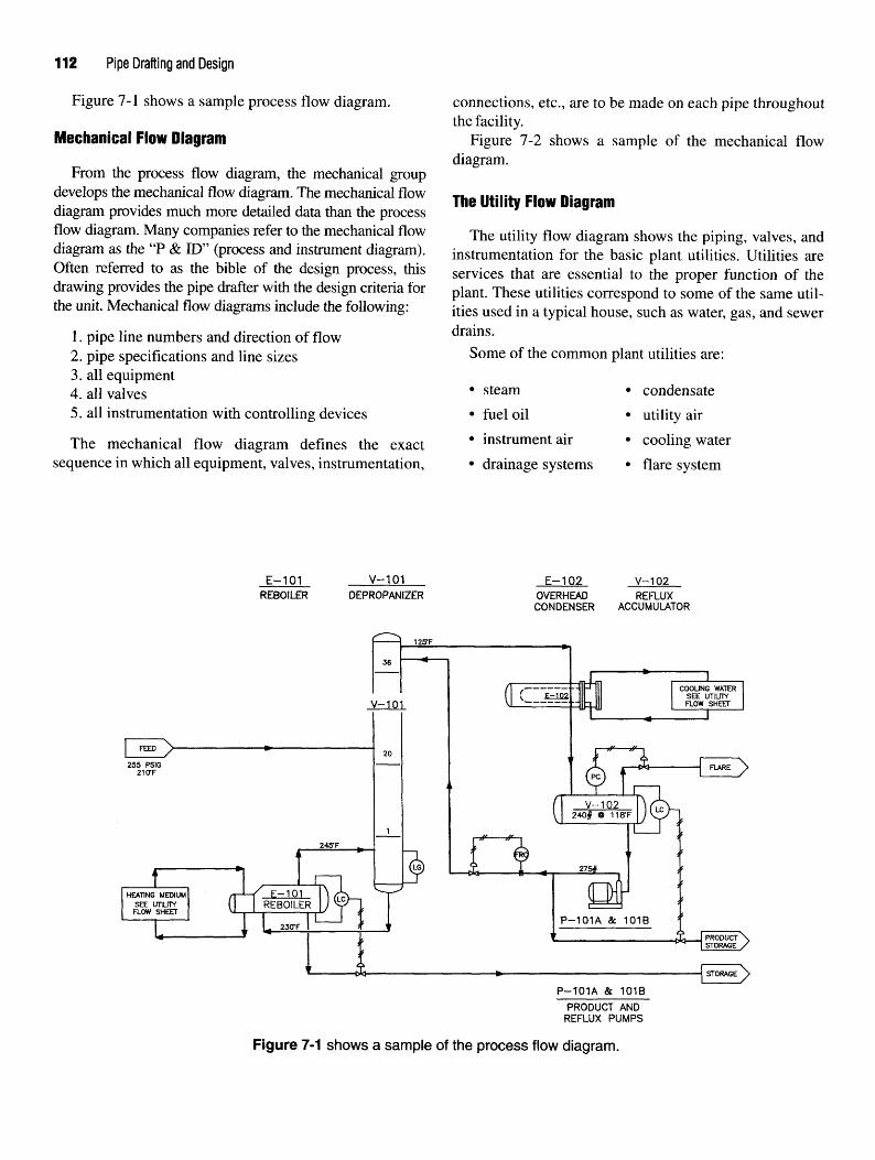
112 Pipe Drafting and Design
Figure 7-1 shows a sample process flow diagram. connections, etc., are to be made on each pipe throughoutthe facility.
Mechanical FlOW Diagram Figure 7-2 shows a sample of the mechanical flowdiagram.
From the process flow diagram, the mechanical groupdevelops the mechanical flow diagram. The mechanical flow TU^ „..,.. e, „.,. . , , , , i , , , The Utility Flow Diagramdiagram provides much more detailed data than the processflow diagram. Many companies refer to the mechanical flow The utility flow diagram shows the piping9 valves> and
diagram as the "P & ID" (process and instrument diagram). instrumentation for the basic plant utilities. Utilities areOften referred to as the bible of the design process, this services that are essential to the proper function of thedrawing provides the pipe drafter with the design criteria for plant These utilities correspond to some of the same util-the unit. Mechanical flow diagrams include the following: ities used in a typical house5 such as watei. gas? and sewer
1. pipe line numbers and direction of flow drains.2. pipe specifications and line sizes Some of the common plant utilities are:3. all equipment4 an valves * steam • condensate5. all instrumentation with controlling devices • fuel oil • utility air
The mechanical flow diagram defines the exact * instrument air • cooling watersequence in which all equipment, valves, instrumentation, • drainage systems • flare system
Figure 7-1 shows a sample of the process flow diagram.

Figure 7-2 shows a sample of the mechanical flow diagram.

114 Pipe Drafting and Design
The flow diagram is a dynamic document. It may be revised Figure 7-4 illustrates a combination of the symbols andand updated during the project to reflect the client's changes or abbreviations used to represent an instrument's functionmodifications imposed by governmental regulations. on flow diagrams. The first letter in the symbol indicates
Figure 7-3 shows a sample utility flow diagram. the instrument group, and the second and/or third lettersindicate the instrument type.
ci nui niAPDARfl IUCTDIIMEUTC To indicate a change or to control the flow, level, pres-FLOW DIAGRAM INSTRUMENTS sure? Qr temperature9 an instrument must first sense a
change in the variable. Once a change has been detected,Instruments function by sensing changes in the vari- the instrument then transmits this information via
ables they monitor. The four basic instrument groups are: mechanical, electronic, or pneumatic means to a controlFlow (F) panel where it can be observed and recorded. At the sameLevel (L) time, the instrument may activate other devices to affectPressure (P) ancj change process conditions in the facility. SomeTemperature (T) instruments are read in the plant at the instrument's actual
The types of instruments used to sense, control and location. Others are displayed on a control panel locatedmonitor these variables are: in an operator's control room.
Controller (C)Indicator (I) Instrument TypesGauge (G)Alarm (A) Gauges. Gauges are instruments that measure the liq-Recorder (R) uid level inside a vessel or the temperature and/or pres-
By learning these nine terms, students will be able to sure in the piping system. Level, temperature, or pressureunderstand most of the instrument symbols found on a gauges are locally mounted to enable plant operators tomechanical flow diagram. obtain a visual reading.
Figure 7-3 shows a sample of the utility flow diagram.

Flow Diagrams and Instrumentation 115
Figure 7-4 Flow diagram instrument symbols.

116 Pipe Drafting and Design
Figure 7-5. Flow diagram and abbreviations.

Flow Diagrams and Instrumentation 117
Controllers. Devices used to maintain a specified liq- symbols have some resemblance to the actual pieces ofuid level, temperature, pressure, or flow inside a vessel or equipment in the field,piping system. They activate the control valve that regu-lates the level, temperature, pressure, and flow in and out _, nill m Ail ADDAuncMcuTof the vessel PLOW PLAN ARRANGEMENT
Alarms. Signals via lights or horns that indicate theliquid level, temperature, or pressure inside a vessel is too The flow Plan should be arranged in a logical order ofhigh or too low or that there is no flow or reverse flow. flow- The mam flow through the umt should be obvious
Indicators. Devices used to indicate the liquid level, by even a bnef examination of the flow plan. Use thetemperature, pressure or flow rate inside a piping system. following checklist as an aid when developing a flow
Recorders. Devices used to record the liquid level, diagram,temperature, pressure, and flow rate inside a vessel orpiping system throughout a certain shift or period of time. ' Avoid crossing lines where Possible"
These same instruments may be found in combination ' SPace e1uiPment ™the sketch to avoid overcrowding,such as Level Recording Controller. Here the instrument * Use notes with symbols where necessary for clarity-not only records the liquid level but also sends a signal to ' Use arrows to show flow directlon-a control valve to control the liquid level inside the vessel. * Show e<luiPment numbers when * is necessary to
identify equipment.• Show control systems on the sketch. The control
PIPINP QYMRfll QririNti o i WOULD scheme is frequently the most important part of aflow plan sketch.
Figure 7-5 shows some flow diagram piping symbols. • Show important valves, orifice flanges, and controlNotice all valves, no matter the pipe size and pound rat- valves.ing, are drawn the same size. Generally, nozzles and • Show flow directions through exchangers withreducers are not shown on the mechanical flow diagram. arrows.The flow diagram in Figure 7-2 shows reducers in order • Do not run lines diagonally across the drawing,to aid the students in visualizing and understanding the • Label feed lines entering the unit from the fieldflow diagram and its relationship to the actual piping where the line enters the unit. Label product linesarrangement drawing. Symbols used on flow diagrams leaving the unit by name,represent the actual piece of equipment. Typically these • Do not draw lines any closer together than necessary.

118 Pipe Drafting and Design
CHAPTER 7 REVIEW QUIZ
1. List five items shown on the process flow diagram.
2. List five items shown on the mechanical flow diagram.
3. List the four basic instrument groups.
4. List the five instrument functions.
5. What type of instrument is used to maintain a certain liquid level?
6. Identify the following instrument abbreviations:a. LGb. FAc. TId. PCe. TRCf. LC
g. PSVh. HCVi. LAHj. LAL
7. Identify the following flow diagram abbreviations:a. DFb. SCc. CSOd. LCe. NO

Flow Diagrams and Instrumentation 119
EXERCISE INFORMATION Exercises 1,2, and 3
Use the instructions accompanying Figure 7-6 to create Recreate the flow diagrams as shown. Using thethe flow diagram symbols with AutoCAD as shown. Use symbols in Figure 7-6 where applicable. Symbols repre-the BASE command to place the base point as indicated. senting other pieces of equipment can be developed on anBLOCK each object using the exact symbol name pro- as-needed basis. Although equipment is not drawn tovided. OOPS the symbol to redisplay. SAVE the drawing scale, it should be proportional to the other symbols usedas FLOSYMBL. in the drawing.
FLOW SHEET SYMBOLS
TO DRAW FLOW SHEET SYMBOLS SET GRID TO .125 AND SNAP TO .0625THE .125 GRID SHOWN BELOW HAS BEEN ENLARGED FOR BETTER VISUALIZATIION.
DRAW AND BLOCK EACH SYMBOL. BASE POINT ( '& ) &
SYMBOL NAME [NAME] HAVE BEEN INCLUDED FOR PROPER IDENTIFICATION.
Figure 7-6. Flow diagram exercise symbols.

EXERCISE 7-1
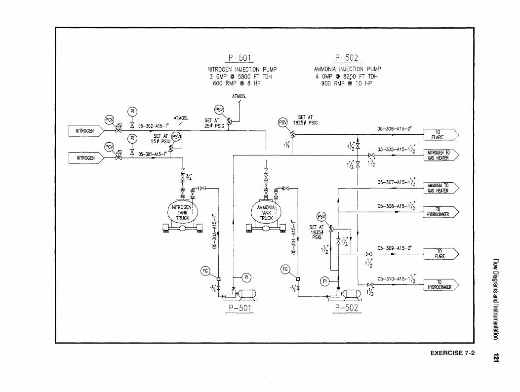
EXERCISE 7-2

EXERCISE 7-3

Codes andSpecifications
As anyone who has ever played a game can tell you,there are specific rules that must be followed if the gameis to be played correctly. The same holds true for buildinga piping facility. Just as the rules of a game establish thebasic guidelines for play, codes and specifications estab-lish guidelines for piping facilities to ensure everythingfrom quality construction to worker safety.
Codes are a broad-based set of guidelines that governthe total scope of a project. Codes originate from a num-ber of sources. Some sources are governmental agenciessuch as OSHA or the EPA and some are organizationssuch as ANSI (American National Standards Institute)that developed the Petroleum Refinery Piping CodeB31.3 that governs operational procedures for refinerypiping.
Specifications, on the other hand, are developed as aspecific set of guidelines for design, fabrication, and con-struction of a piping facility. Written to maintain consis-tency and uniformity throughout all phases of a project,specs are very detailed. Codes can be as broad as state-ments indicating that all facilities must be built in accor-dance with ANSI standards, while specs are so detailedthey can include instructions to a painter indicatingwhich pipe to paint red.
As we look at codes and specs, remember that theyhave been developed through years of trial and error.When something purchased didn't fit, something builtbroke, or something boiled blew up, someone made anote of the mistake, remembered it the next time a similarsituation occurred, and made it an operational procedure.The operational procedure evolved into a piping code.
CODES
Though you may not be familiar with codes specific topiping facilities, you are familiar with an ordinary structureto which codes also apply: the typical house. Codes havebeen written concerning door sizes, window sizes, lumbersizes, electrical requirements, etc. As an example, the min-imum width of a front entry door is 3'-0". Windows in
sleeping rooms must have a net area of 5.7 sq. ft. with aminimum opening height of 2'-0" and width of 1 '-8".
Codes for piping facilities have been implemented in asimilar fashion. Regulations have been established forpressure and temperature limits, material compositionand stresses, worker safety, emergency evacuation proce-dures, and many more. Table 8-1 provides a partial listingof the codes written for piping facilities.
Table 8-1Piping Facility Codes
Code Designations
ANSI B3 1.1ANSI B3 1.3ANSI B3 1.5ASME
Titles
Power PipingPetroleum Refinery PipingRefrigeration PipingBoiler and Pressure Vessels
SPECIFICATIONS
As previously mentioned, specifications stipulate spe-cific details for design, fabrication, and construction.Specifications are used by many groups to achieve a com-mon goal. Engineers, designers, and drafters must usespecs to establish sizes, pound ratings, and dimensions ofpipe and equipment. Stress calculations are made frominformation provided in the specs to ensure columns,beams, and supports will withstand the loads and forcesplaced on them. Purchasing personnel need specs toensure proper materials and equipment are bought. Weld-ers and fabricators use specs to erect structures, supports,and route the proper size pipe. Specs also provide work-ers installing instrumentation controls proper temperatureand pressure settings.
Specs for a house might include the drawing scale towhich the construction drawings were created. They mayrequire the use of a particular grade of lumber or specifythe thickness of insulation to be installed in the attic.Specs inform someone which color of carpet to buy orfrom what manufacturer to order the water heater.
123

124 Pipe Drafting and Design
When applied to a piping facility, specs become quite 6.5 Flow arrows will indicate flow direction of each line,lengthy. Comprising volumes of printed material, specs Line numbers shall be assigned to each pipe line. Aoften seem never-ending. Two sample sections from a typical line number is shown in Figure 8-1.typical specification document are provided below. 7.0 Clearances and Accessibility
7.1 Roadways7.1.1 Minimum headroom clearance over secondary road-
6.0 Drawings and Design Procedures ways is lO'-O".6.1 Piping arrangement drawings are plan views that 7.1.2 Minimum width of secondary roadways is lO'-O"
show pipe in sufficient detail to indicate pipe routing, excluding 3'-0"shoulders.anchors, guides, supports, intersections, and provisions 7.2 Walkwaysfor expansion. 7.2.1 Maintain a minimum headroom clearance of 7'-0".
, n n. . , . , „ , 7.2.2 Maintain a minimum horizontal clearance of 2'-6".6.2 Piping arrangement drawing dimensions shall be 7 7 pi tf
shown in feet and inches. Inches shall be used when _\ ^ A/ r. . , ~ . ,,u . ~, ,-„.. _„ _ . . .„ , 7.3.1 Minimum platform width is 2-6 .dimensions are less than 1 -0 . Dimensions will be „ , , „ . , , . . , , , , , . f7.3.2 Minimum headroom clearance above platforms isshown to the nearest Me . 7'_0"
6.3 Intersecting coordinates will be used to position all 7.3.3 Platforms shall be placed 2'-6" below the centerlinebuildings, pipe supports, and equipment. Equipment of manways.shall include vessels, pumps, exchangers, boilers, heat- 7.3.4 Maximum vertical distance between platforms (lad-ers, and cooling towers. der length) is 30'-0".
11 1 TV u n u j - • j r j- „. * u 7.3.5 Minimum clearance around any platform obstruc-6.3.1 Pipe shall be dimensioned from coordinates to show , J r
location. Elevations shall be used to indicate height ~ ,-, ^ ^ - j r - i - u 0/ ™ ^ ^7.3.6 Cages are not required for ladders 8-0 long or less
measurements. t ® , ,\r.. _... , , , , . ,or ladders that end 20-0 or less above the high point
6.4 Standard piping symbols shall be used throughout. of paving.Piping drawings shall be drawn to a y8" = l'-0" scale. 7.3.7 Platforms shall be provided for manways whichDetail drawings shall be larger as necessary. Pipe 12" have a centerline 15'-0" or higher above high point ofand smaller shall be drawn single line. Pipe 14" and paving.larger shall be drawn double line. In congested areas An example of how specifications are applied to pipingdouble line drawings may be used for clarity. drawings is represented in Figure 8-2.
Figure 8-1. Line number.

Codes and Specifications 125
Figure 8-2. Application of specifications.
SPECIFICATION CLASSES
As extensive as specifications are, they should not beconsidered all encompassing. Specifications are dividedinto classes developed especially for particular services.Classes are categorized by the commodity within thepipe. They take into account whether the commodity is agas or liquid, as well as design and operating tempera-tures, pressures, and corrosiveness. Figure 8-3 providesan index of classes. It includes the class designation,flange type and ratings, material, and service commoditytype.
Specification classes use service parameters to estab-lish flange pound ratings, pipe wall thickness, pressureand temperature limits, as well as the type of connectionsto be used, that is, screwed, socket-weld, butt-weld, etc. Figure 8-3. Index of specification classes.

126 Pipe Drafting and Design
Specification classes are extremely detailed. They specify Bwhich manufacture to purchase valves from as well as thespecific part model number to be used. Specs specify the B Beveledmaterial gaskets will be made of and whether branch con- BB Bolted Bonnetnections are to be made using straight tees, reducing tees, BBE Bevel Both Endsor stub-ins. Specifications also stipulate corrosion allow- BBL Barrel(s)ance values. Corrosion allowance is the amount of surface "^ °°^ Circlematerial allowed to be eroded by the commodity within BD Blow Downthe pipe while permitting the pipe to remain usable for the "^ Beveled End(s)particular service for which it is installed. "* Blind Flange
The examples of specification classes that follow are to "L Battery Limitsbe used throughout the projects in this text. Use them as a BLDG Buildingguide to answer specific questions about the design and BLE Bevel Large Enddrafting of a piping system. As with all specifications, they BOM Bill of Materialsare to be used only with the project for which they are writ- BOP Bottom of Pipeten and should not be considered typical for every project. B&S Bell and Spigot
BSE Bevel Small EndBTU British Thermal Unit
ABBREVIATIONS BV Ball ValveBW Butt-weld
As a piping facility becomes more complex, so do thepiping drawings. Facilities such as multi-storied struc- Ctures, specialized refining systems, and complex equip-ment arrangements compound the crowdedness of a Catch Basindrawing. To alleviate the crowded conditions, abbrevia- CHKV Check Valvetions should be used to reduce the space requirements of ^"* ̂ P' Chain Operatorcallouts and notes. The following is an alphabetical list- ^ ^ast Iron
ing of many common abbreviations found on piping ^ clearancearrangement drawings, flow diagrams, or isometrics. A ^^ clean Outcomplete listing is almost impossible to assemble because COL Columnengineering companies and their clients often have abbre- COLS Columnsviations that are particular to specific situations. COJNC Concentric
COND CondensateCONN ConnectionCORK Corrosion
PIPING ABBREVIATIONS CPLG Coupling
CS Carbon SteelA Cast Steel
Cold SpringA Alarm CSC Car Seal ClosedA Anchor cso Car Seal Open
ACCUM Accumulator CTRLV Control ValveAL Aluminum CWR Cooling Water Return
ANSI American National Standards Institute CWS Cooling Water SupplyAPI American Petroleum Institute
ASSY Assembly QASTM American Society for Testing and Materials
ATMOS Atmosphere DA Directional AnchorAUX Auxiliary DF Drain FunnelAVG Average DIA Diameter
AZ Azimuth DIM Dimension

Codes and Specifications 127

128 Pipe Drafting and Design

Codes and Specifications 129
DISCH Discharge HDR DrainDW Dummy Weld HCV Hand Control Valve
DWG Drawing HDR HeaderDRWN Drawn HIC Hand Indicating Controller
HLL High Liquid LevelE HOR Horizontal
HP High PressureT™ !̂ aSt • HPFS High Point Finished SurfaceECC Eccentric TTT»T» u- u n • * n •HPP High Point Paving
EL Elevation „„ „ ° „ ,HR Hanger RodELL Elbow TT_,_. __7 _ . Hour
ELEV Elevation TTTTJ TT «.FOTTTP F HTR Heater
un«7 c?U1fmT • . «r u j HVAC Heating, Ventilating, and Air ConditioningERW Electric Resistance Welded TT*™/ u
T7vr-Ti c u HVY HeayyEXCH Exchanger TTVJ\ u A rEXIST Existing HYD HydraU'1C
F '
FA Flow Alarm IA Instrument AirFBO Furnished By Others Insulation (anti sweat)FDN Foundation 1C Insulation (cold)
FE Flow Element ID Inside DiameterF/F Face-to-Face H)D Inside Depth of DishFF Flat Face IET Electric Trace
Full Face IGT Glycol TraceFI Flow Indicator IH Insulation (heat conservation)
FIC Flow Indicating Controller IN Inch(es)FIG Figure INS Insulate or InsulationFLR Floor INST Instrument(ation)
FLDFAB Field Fabricate INV Invert ElevationFL Flange IPS Iron Pipe Size
FOB Flat on Bottom IS Insulation SafetyFOT Flat on Top ISA Instrumentation Society of America
FR Flow Recorder ISO International Organization forFRC Flow Recording Controller Standardization
FS Field Support IsometricForged Steel 1ST Steam Trace
FT Foot or FeetFW Field Weld J
Q JCT JunctionJS Jack Screw
G Gauge or gage JT JointGAL Gallon(s)
GALV Galvanized LGPH Gallons Per HourGPM Gallons Per Minute L Level
GR Grade LA Level AlarmGaV Gate Valve LAH Level Alarm-HighGIV Globe Valve LA.L Level Alarm-Low

130 Pipe Drafting and Design
LBS Pounds NPT National Pipe ThreadLC Level Controller NTS Not to Scale
Lock ClosedLG Level Gauge 0
Level GlassLI Level Indicator OAL Overall Length
LIC Level Indicating Controller OD Outside DiameterLLL Low Liquid Level OH Open Hearth
LN Line OPP OppositeLO Lock Open OS&Y Outside Screw and YokeLP Low Pressure OVHD Overhead
LPG Liquefied Petroleum Gas ows OilY Water Sewer
LPT Low PointLR Level Recorder "
Long RadiusT nr* T i r> j- ^ * n pA Pipe AnchorLRC Level Recording Controller „ r
¥ o T i o V u Pressure AlarmLS Level Switch _ _ _ _PC Pressure Controller
ly. PCV Pressure Control ValvePdRC Pressure Differential Recording Controller
mm millimeter PE Plain EndM Meter p^ Point of Intersection
M&F Male and Female Pressure IndicatorMATL Material PIC Pressure Indicating ControllerMAX Maximum P&ID Piping and Instrument Diagram
MECH Mechanical PLE Plain Large EndMFG Manufacturing PO Pump OutMFR Manufacturer POE Plain One End
MI Malleable Iron POS PositiveMIN Minimum pp Personnel Protection
Minute PR Pressure RecorderMISC Miscellaneous PRC Pressure Recording Controller
MK Piece Mark PS Pipe SupportMW Manway PSE Plain Small End
Miter weld P^I Pounds per Square InchPSIA Pounds per Square Inch absolute
H PSIG Pounds per Square Inch GagePSV Pressure Safety Valve
N North PT PointNC Normally Closed
NEC National Electric Code QNEG NegativeNIP Nipple QTY Quantity
NLL Normal Liquid Level QUAD QuadrantNO Normally Open Quadruple
NumberNOM Nominal R
NOZZ Nozzle „ „ J.XTTJC. XT • i TV o- R RadiusNFS Nominal Pipe Size ^T-^TA n • j
xTT»om X T * « •*• o *• TT j REC'D ReceivedNPSH Net Positive Suction Head ^^^ _ ,RED Reducer

Codes and Specifications 131
REF Reference THRD ThreadREINF Reinforce TI Temperature IndicatorREQ'D Required TIC Temperature Indicating Controller
REV Reverse TLE Thread Large EndRevision TOC Top of Concrete
RF Raised Face TOG Top of GroutRJ Ring Type Joint TOL Threadolet
RPM Rotations Per Minute TOS Top of SteelRS Rising Stem TR Temperature Recorder
RTJ Ring Type Joint TRC Temperature Recording ControllerTSE Thread Small End
S T/T Tangent to TangentTW Temperature Well
s South ThermowellSC Sample Connection TYP Typical
SCH ScheduleSCRD Screwed ySECT Section
SH(SHT) Sheet UA Utility AirSMLS Seamless US Utility Station
SO Slip OnSteam Out V
SOL SockoletSP Set Point VA Valve
SP GR Specific Gravity Vent to AtmosphereSPEC Specification VB Vortex Breaker
SQ Square vc Vitrified ClaySR Short Radius VERT Vertical
STD Standard VF Vent to FlareSTL Steel VOL Volume
STM Steam vs Vent to StackSUCT SuctionSUPT Support W
SW Socket-weldSWG Swage w/ with
SWP Standard Working Pressure W West
SYS System WB Welded BonnetWE Weld End
T WLD WeldWN Weld Neck
T Steam Trap WOG Water, Oil, GasTA Temperature Alarm WOL Weldolet
Tan Tangent WT WeightTBE Thread Both Ends
TC Temperature Controller XTCV Temperature Control Valve
TE Threaded End XH Extra HeavyTEMP Temperature XS Extra Strong
T&C Thread and Coupled XXH Double Extra HeavyT&G Tongue and Groove XXS Double Extra Strong

132 Pipe Drafting and Design
CHAPTER 8 REVIEW QUIZ
1. Explain the difference between codes and specifications.
Using information found in the sample piping specifications, answer the following questions.
2. Dimensions are provided on drawings to the nearest of an inch.
3. Piping drawings are drawn to which scale?
4. What is the minimum headroom clearance of a secondary roadway?
5. What is the minimum headroom clearance over a walkway?
6. What is the minimum horizontal clearance of a walkway?
7. What is the minimum width of a platform?
8. What is maximum vertical distance between platforms?
9. Cages are not required on ladders feet long or less.
10. What is the purpose of specification classes?

Equipment Layout
PLANT COORDINATE SYSTEMS
Plot plans, foundation location drawings, and equip-ment location drawings are developed using the plantcoordinate system. Universally recognized throughout thepiping industry, the plant coordinate system uses intersect-ing grid lines, similar to the Cartesian coordinate system,to locate buildings, structures, foundations, equipment,and piping configurations. These intersecting grid lines,which originate from a designated control point, are drawnparallel to the north/south and east/west axes.
The control point, more commonly known as a benchmark, is a permanent marker erected in a remote area ofthe piping facility. It is often located so it will not be acci-dentally damaged or destroyed. The control point is usedas the origin from which the intersecting north/south andeast/west lines are labeled as coordinates using numericalvalues. The control point, therefore, becomes the primaryreference point for the entire facility. By defining the con-trol point as O'-O", O'-O" and using a north arrow to estab-lish orientation, the numerical values assigned to thecoordinates allow for exact positioning of all facility com-ponents. Coordinates indicate the measurement from thecontrol point to the particular structure, foundation, orpiece of equipment that the coordinate locates.
North arrows are typically pointed up or to the right ona drawing and help create directional bearing in the facil-ity. Lines above, or north of, the O'-O", O'-O" control pointare assigned north coordinates and are labeled to indicatetheir distance from the control point, for example, N. 5'-0".Lines to the right of O'-O", O'-O" are assigned east coordi-nates, for example, E. 5'-0". Coordinates to the south andwest of the control point will have S. or W. prefixes,respectively. See Figure 9-1 for an example of the plantcoordinate system.
The format used to identify plant coordinates will varywith each design project. Some projects use feet and inchdesignations while others may use decimals of a foot ormillimeters. No matter the format, all coordinates are
preceded by the letters N, S, E, or W. The project in thistext will use feet and inches with the metric equivalentshown beneath. Location dimensions used on pipingarrangement drawings are placed to reference a knowncoordinate, usually the center line of a column, founda-tion, or piece of equipment.
A control point is also used to establish the elevation ofthe piping facility. Elevation is the vertical distance anobject measures above sea level, such as the height of amountain. Piping facilities use elevations to designate theheight an object measures from grade. Grade is a pipingterm that is synonymous with ground. Rather than usingnumbers based on the actual height above sea level, mostfacilities use an arbitrary elevation of lOO'-O" as a matterof convenience. Facilities located within high-rise struc-tures may use elevations based on the height of the vari-ous floors within the structure. In all petro-chemicalfacilities, pipes are installed both above grade and belowgrade. The use of lOO'-O" as a point of reference preventsthe use of negative numbers when dimensioning linesbelow grade.
Few actual dimensions are provided on piping sectionor elevation drawings. However, numerous callouts areplaced on drawings to convey elevation information to thereader. Some of the callouts and corresponding terms areshown below.
See Figure 9-2 for examples of the plant elevationsystem.
Piping Terminology
grade elevationhigh point of pavingcenter line elevationtop of concretetop of steelbottom of pipeface of flangetop of platform
Piping Callout
GRADE EL.IOO'-O"H.P. PAVING lOO'-O"IEL. i02'-o"T.O.C. EL. 101 '-0"T.O.S. EL. 112'-0"B.O.P.EL. 112'-0"F.O.F. EL. 105 '-0"TO. PLAT. EL. 137'-6"
133
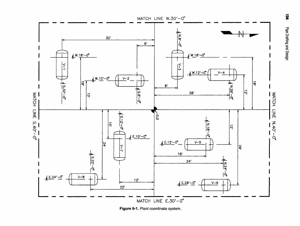
Figure 9-1. Plant coordinate system.

Figure 9-2. Plant elevation system.

136 Pipe Drafting and Design
The repeated use of coordinates and elevations makes drawn to one of the following scales: 1" = 10', 1" = 20', orit imperative that correct numbers be used to calculate 1" = 30'.accurate dimensions. To avoid inadvertent mixing of Unit plot plans show the location of all the buildings,coordinate and elevation values, follow this simple guide- equipment, pipe racks, and other items of importance inline: Use only coordinates to calculate horizontal dimen- the unit. True north and plant north are also shown. Thesions and use only elevations to calculate vertical purpose of this drawing is not to show detail, but rather,dimensions. By adding or subtracting coordinates, hori- the arrangement of various components to be erected inzontal distances between supports, foundations, and the unit.equipment can be determined. Knowing when to add and The piping group is typically responsible for the devel-when to subtract can be confusing, however. The basic opment of the unit plot plan. Unit plot plans are devel-rule to remember when calculating horizontal distances oped using the mechanical flow diagram, clientis: Subtract like coordinates and add unlike coordinates. specifications, codes, and input from the client's engi-This basic rule is illustrated in Figure 9-3. neers, and the plant manager who will ultimately oversee
Calculating vertical dimensions is somewhat easier. the operation of the facility. Figure 9-5 shows an exampleSimply subtract the lower elevation from the higher eleva- of a unit plot plan,tion to determine the distance between the two. However,you must be certain that elevations of the same type are cnmnMciiT i nnATinu nnAununused. For example, always use two centerline elevations, EQUIPMENT LOCATION DRAWINGnot one centerline and one bottom of pipe. It is best to con-vert B.O.P. elevation callouts to centerline elevations before In order to arrange and adequately space equipment,subtracting. This is accomplished by adding one half the the piping group will use the approved plot plan to assignactual OD of the pipe to the B.O.P. elevation. Also be coordinates to mechanical equipment, pipe supports, andaware that lines installed below grade are labeled using control rooms. Keep in mind there will be plant operatorsinvert elevations. Invert elevations identify the inside bot- and maintenance personnel in the facility 24 hours a day.torn of pipe elevation, that is, the distance from the bottom Adequate arrangement and spacing of components withininside of the pipe to the ground above it. Figure 9-4 illus- the facility depend on a number of factors, including pip-trates the use of elevations to calculate vertical dimensions. ing codes, space availability, worker accessibility as well
as client preferences. All pieces of mechanical equipmentQITP PI ANQ to ̂ e installed within the facility are positioned using two
intersecting coordinate lines, one north/south and oneeast/west. These intersecting coordinates define the pre-
The civil/topographic drafting department of a com- cise position of the equipment by locating the centerlinepany prepares the site plans for the piping facility. Site of its foundation. When locating equipment such asplans are overhead views drawn to show the overall facil- exchangers and reboilers that have a foundational supportity site and adjacent areas that may include roadways, on each end? at least one of the equipment's supportingrailways, harbors, ship channels, and aircraft landing foundations must be located with coordinates. By usingzones. Drawings of this size do not show significant me plant coordinate system, it is impossible for any otherdetail. Detailed areas of the facility are usually denoted component in the facility to have the same pair of inter-by rectangular outlines with notes or titles describing the secting coordinates. Figure 9-6 shows an example of anarea's purpose. Mechanical equipment within the facility equipment location drawingis typically too small to be represented on a site plan. |Therefore the complete facility is usually divided into cmiMnATinu nrATIOU nDAUfiur Ismaller areas called units. Each unit can then be drawn FOUNDATION LOCATION DRAWINGseparately on drawings called unit plot plans.
The structural drafting department uses informationprovided on the equipment location drawing to show the
UNIT PI ilT PI ANum i FLU i TLHII position of foundations for equipment, structural support,and control buildings. On foundation location drawings,
Unit plot plans are generally defined by imaginary foundations that are to be built above grade are drawn aslines called battery limits. Battery limits are used to estab- solid lines and spread footings. The portion of the founda-lish a unit's boundaries. The unit plot plan is usually tion that lies below grade is shown as hidden lines.

Figure 9-3. Coordinates.

Figure 9-4. Elevations.

Figure 9-5. Unit plot plan.

Figure 9-6. Equipment location drawing.

Equipment Layout 141
PIPING DRAWING INDEX possible. These drawing areas are given a drawing num-ber for easy identification and then assigned to various
The piping drawing index is developed from the plot designers on the project. During the design phase, it isplan. This drawing divides the plot plan into smaller crucial that designers interface with those working ondrawing areas, using match lines. Match lines are lines adjacent drawing areas. The position, size, and pound rat-drawn and labeled that allow the smaller drawing areas to ing of lines entering or leaving an area and continuingbe pieced together to form the larger plot plan, similar to into an adjacent area must be properly noted and locateda puzzle. Larger areas are divided in such a way as to on all related drawings. Figure 9-7 shows an example ofkeep related pieces of equipment on the same drawing if the piping drawing index.
Figure 9-7. Piping drawing index.

142 Pipe Drafting and Design
CHAPTER 9 REVIEW QUIZ
1. Define plant coordinate system.
2. Name the three units of measurement by which coordinates can be labeled.
3. What is the typical arbitrary value for the elevation of grade?
4. Define the following terms.
H.P. Paving
T.O.C. EL.
T.O.S. EL.
B.O.P. EL.
F.O.R EL.
5. Use only coordinates to determine dimensions.
6. Use only elevations to determine dimensions.
7. Define battery limits.
8. Name three factors that influence the arrangement and spacing of equipment.
9. How are above-grade foundations represented on a foundation location drawing?
10. What is a match line?

PipingArrangementDrawings, Sections,and Elevations
ARRANGEMENT DRAWINGS
The arrangement drawing is the most significant draw-ing developed by a piping designer. This plan view draw-ing is a major source of information used in thefabrication and erection of the piping facility. Informa-tion on the arrangement drawing aids in the developmentof the piping model and isometric drawings.
The piping arrangement drawing evolves from thefoundation location and equipment location drawings. Itshows all mechanical equipment and vessels in the unitand the pipes connecting them, including manholes, lad-ders, platforms, and davits. It identifies all structural sup-ports such as pipe racks, equipment structures, columns,braces and any flreproofing they may have. Once loca-tions for foundations and equipment have been estab-lished, piping configurations are added to the drawingwith the aid of symbols that represent fittings, flanges,and valves.
Written information placed on the arrangement draw-ing includes equipment coordinates, identification num-bers, elevation callouts, line numbers, flow arrows, anddimensions establishing pipe locations. Instrumentationsymbols are included to indicate type, position, and ori-entation for accessibility by plant personnel. Ladders andplatforms are also shown on equipment and structuresthat have them. A nozzle schedule is included that con-tains detailed information about all piping and instrumentconnections for every piece of equipment. Information
such as nozzle number, size and pound rating, orienta-tion, elevation, and projection is also included. With somuch required information on a drawing, it is easy tounderstand why the piping arrangement drawing must beneat, accurate, and legible.
RESPONSIBILITIES OF THE PIPING DESIGNER
Only after many years of experience does the drafterbecome a piping designer. The time invested in learningcompany specifications, layout procedures, and equip-ment requirements makes the designer a valuableemployee.
As the arrangement drawing is being developed, a pip-ing designer should consider the following:
How can the drawing be simplified? How will con-struction, repairs, and routine maintenance be performedin this unit? Has enough room been provided for accessbetween equipment? Foremost on a designer's mindshould be the safety and protection of plant operators andmaintenance personnel.
INFORMATION SOURCES FOR PIPINGARRANGEMENT DRAWINGS
A piping designer must assemble the various referencedrawings and documents needed to lay out the pipingarrangement drawing. These may include:
143

144 Pipe Drafting and Design
• mechanical flow diagram• plot plan• foundation or equipment location plan• piping index drawing• equipment (vendor) drawings and foundation draw-
ings• piping specifications• pipe line list• list of special requirements, if any, for the project
LAYOUT PROCEDURES
To develop a piping arrangement drawing, the designermust be familiar with company and client job specifica-tions and requirements of the current project. Many differ-ent layout and design techniques can be used dependingon client requirements, company policy, budget limita-tions, manpower, and available computer software.
Piping arrangement drawings are quite complex andcongested. Therefore a systematic layout procedure isrecommended to ensure all necessary items are included.The following are the recommended procedures for lay-out of piping arrangement drawings.
1. Define proposed area outline or drawing match lines.2. Fill in drawing number and title block information.3. Place a north arrow in upper right-hand corner of
the drawing.4. Locate foundations for buildings, pipe rack col-
umns, and mechanical equipment from the coordi-nates used to develop the foundation locationdrawing and dimensions provided on the equip-ment foundation drawing.
5. Draw equipment foundations.6. Lay out equipment.
NOTE :
• Show only enough detail on equipment outlines toprovide a generalized description.
• Represent equipment centerlines, outlines, and foun-dations with thin dark lines.
• Show all piping and instrumentation connections(nozzles, couplings, etc.) on equipment.
7. Prepare a study drawing of each individual pipingconfiguration in the facility. This procedure willallow the designer to explore all requirements nec-essary for design, operation, and maintenance priorto the final layout.
8. Lay out the piping system as shown on the studydrawing. Include instrumentation connections onthe piping configuration. Note that every pipingfacility has different process, mechanical, and instru-mentation requirements. It would be extremely diffi-cult to establish set rules and procedures formethods of piping development. Each line on thelayout is, in itself, a special design problem andmust be dealt with accordingly.
9. Add platforms, ladders and cages, pipe guides,anchors, supports, and hangers as required.
10. Include line numbers, codes, specs, specialty itemnumbers, and callouts.
11. Place locating dimensions for piping.12. Label coordinates for equipment, pipe supports,
etc., if required for job.13. Add instrument balloons and callouts.14. Include nozzle schedules and notes as required.15. Complete drawing. Add match line, area limit, and
battery limit callouts, reference details, and sectionor elevation cutting plane symbols.
16. Print/plot the completed drawing and check yourwork.
17. Correct any mistakes you find before releasing thedrawing to your instructor or supervisor.
PIPING ARRANGEMENT DRAWING LAYOUT
This section provides a detailed explanation of the pro-cedures to lay out the piping arrangement drawing shownin Figure 10-1. These procedures will simulate thoseundertaken on any design project by an actual engineer-ing company. To simplify the layout procedures and con-solidate the reference drawings and related information, acopy of the mechanical flow diagram, foundation draw-ing, equipment foundation drawings, equipment vendordrawings, and the piping specification tables is providedin this chapter.
The following procedures present both manual andAutoCAD methods for developing piping arrangementdrawings. Note that manual drawings should be drawn toyg" = l'-0" scale and CAD drawings are drawn full sizeand plotted to y8" = I'-O" (.03125") scale.
Procedure 1-3: Drawing setup. Locating area and unitboundaries, title block, and north arrow
References Drawing: Foundation location plan andcompany drawing standards
Manual. On a "C" size (18" x 24") sheet of trac-ing vellum, lightly lay out drawing borders mea-suring Vz" inward from the edges of the vellum,
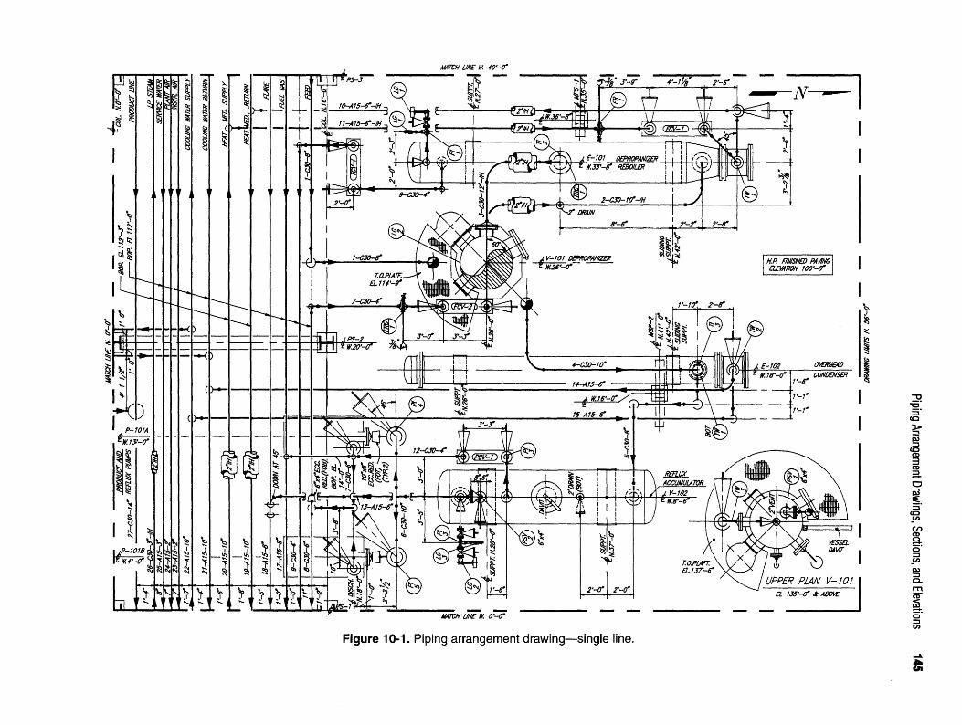
Figure 10-1. Piping arrangement drawing—single line.
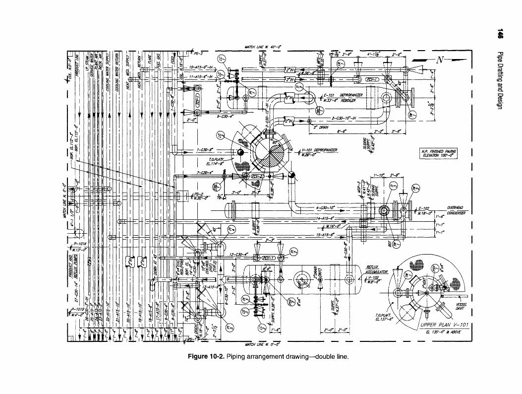
Figure 10-2. Piping arrangement drawing—double line.
Piping Arrangement Drawings, Sections, and Elevations 147
including title block if required. Find the center of thedrawing area by drawing diagonal lines from the oppositecorners of the borders. The intersection of the two diago-nal lines will form the center of the drawing area. Deter-mine the width and depth of the unit's boundaries bysubtracting the smaller match line coordinates from thelarger match line coordinates for both the north/south andeast/west match lines respectively. Divide the width anddepth measurements equally on each side of the drawing'scenterpoint. Lightly layout the unit's match lines with con-struction lines using the 3/g" = l'-0" scale. These lines willbe widened and darkened at the completion of the project.
AutoCAD. Set the UNITS command toArchitectural and the 'smallest fraction' settingto 'sixteenths'. Set LIMITS as follows: lower
left (-5'-0", -5'-0") and upper right (60'-0", 50'-0").ZOOM, ALL. Set GRID to I'-O" and SNAP to 6".Resize these valuable drawing aids as needed throughoutthe project. Set the LTSCALE command to 32.
Create the following layers with corresponding colorsand line types.
Layer name Color Line type
Border Blue Continuous
Matchline White Phantom
Centerlines Yellow Center
Foundations Cyan Continuous
Steel Cyan Continuous
Equipment Green Continuous
Pipe Yellow Continuous
Instruments Red Continuous
Text Green Continuous
Dimensions Magenta Continuous
Make 'Matchline' the current working layer. SetCOLOR and LINETYPE to 'Bylayer'. Figure 10-3 willbe used as a reference to lay out the unit boundarymatchlines from the O'-O", O'-O" origin. Using the PLINEcommand with a line width of 1", draw the unit matchlines.
Procedure 4: Lay out centerlines for pipe rack andequipment foundations
Reference drawing: Equipment location plan
Manual. Lay out the pipe rack and equipmentfoundation centerlines by measuring from the N.O'-O" and W. O'-O" (lower left) corner. Do not
measure from the sides of the drawing borders. If yourborder is incorrect, your centerlines will be located in the
wrong place. Use a .5mm lead. This will keep the center-lines thin and dark.
AutoCAD. Make 'Centerline' the current work-ing layer. Use the OFFSET command to drawlines parallel to the north and west match lines to
represent the intersecting coordinates of the pipe rack andequipment centerlines. EXPLODE each new line. UseCHPROP to change these lines to the 'Centerlines' layer.TRIM or BREAK these lines to create short intersec-tions representing the equipment centerlines.
Once the equipment centerlines are located your draw-ing should appear as shown in Figure 10-4.
Procedure 5: Drawing pipe rack and equipmentfoundations
Reference drawing: Equipment location foundationdrawing (see Figure 10-5) and foundation drawing forindividual pieces of equipment (see Figures 10-6 through10-11).
Manual. Use the coordinates shown on theequipment foundation drawing and the dimen-sions provided on the foundation drawing for
each individual piece of equipment to locate the equip-ment foundations. Foundations located below mechanicalequipment should be drawn with hidden lines. Add piperack and miscellaneous pipe support foundations usingdimensions.
AutoCAD. Make 'Foundations' the currentworking layer. Use the LINE command to drawequipment, pipe rack, and pipe support founda-
tions from coordinates and dimensions shown on theequipment foundation drawings. Use CHPROP to changethe linetype of the foundations located below the mechani-cal equipment from 'continuous' lines to 'hidden' lines.
Your drawing should appear as shown in Figure 10-5when Procedure 5 is completed.
Procedure 6: Equipment layout
Reference drawings: Equipment vendor drawingsUse dimensions provided on the equipment vendor
drawings to lay out the equipment as represented inFigure 10-12. The equipment vendor drawings are shownin Figures 10-13 through 10-18.
Manual. All mechanical equipment is drawnwith dark, thin lines. Use a .5mm lead. Size andlocation dimensions for ladder and platform
details are supplied with vendor drawings V-101 andV-102.
AutoCAD. Make 'Equipment' the currentworking layer. Represent all mechanical equip-ment with the LINE command. Ladder and

Figure 10-3. Unit matchlines.

Figure 10-4. Equipment centerlines.

Figure 10-5. Equipment foundation location drawing.

Figure 10-6. V-101 vertical vessel foundation drawing.

Figure 10-7. V-102 horizontal vessel foundation drawing.

Figure 10-8. E-101 kettle reboiler foundation drawing.

Figure 10-9. E-102 heat exchanger foundation drawing.

Figure 10-10. P-101A and 101B pump foundation drawing.

Figure 10-11. Pipe rack and pipe supports MPS-1 and MPS-2.

Figure 10-12. Equipment location drawing.

Figure 10-13. V-101 vertical vessel.

Figure 10-14. V-101 vertical vessel.

Figure 10-15. V-102 horizontal vessel.

Figure 10-16. E-101 Kettle reboiler.

Figure 10-17. E-102 heat exchanger.
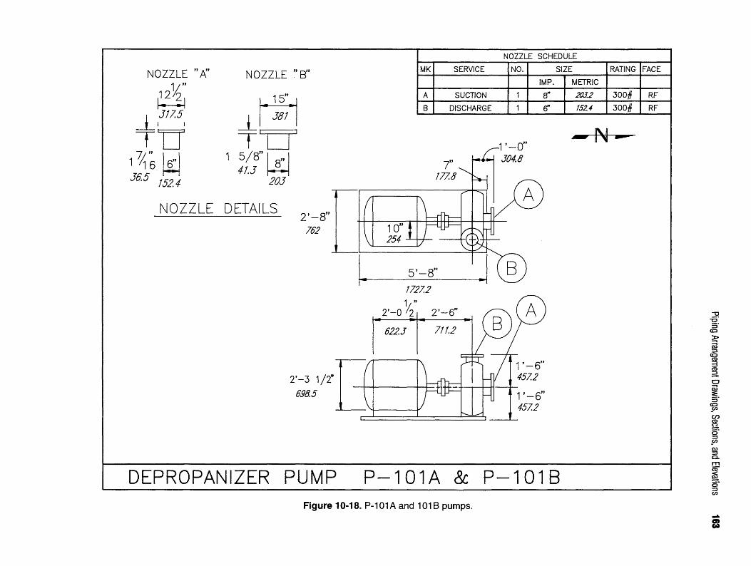
Figure 10-18. P-101A and 101B pumps.

164 Pipe Drafting and Design
platform dimensions are supplied with vendor drawingsV-101andV-102.
Procedures 7 and 8: Configuration of piping systemsReference drawings: Mechanical flow diagram, equip-
ment vendor drawings, and piping specificationsIn procedures 7 and 8, each line will be described rela-
tive to the commodity flow direction. That is, the descrip-tion of the pipe will correspond to the direction of theflow of the commodity within the pipe. Although thewritten description of the pipe does not include exactdimensions required for layout, dimensions for fittings,flanges, valves, and equipment can be found on dimen-sioning charts and vendor drawings. These dimensionswill be needed to place the pipe on the arrangement draw-ing in its proper location and orientation. The 3-D mod-eled views of each line are shown in the upper rightcorner. This view will be especially beneficial when rep-resenting the lines on the arrangement drawing.
Manual. Represent pipe using nominal sizedimensions with a ,7mm lead. For lines 14"and larger, pipe centerlines are drawn with a
.5 mm lead.AutoCAD. Make 'Pipe' the current working
layer. Use the LINE command to draw all lines14" and larger as double-line pipes having actual
OD dimensions. Centerlines for double-line pipes aredrawn with LINETYPE set to 'Center'. Draw any singleline pipe with the PLINE command having a width of.56". The fitting, flange, and valve symbols created in theprevious chapters can be inserted into their appropriatelocations.
Routing
Configurations for lines 01-1-C30-8" through 01-16-C30-2".
As shown in Figure 10-19, line 01-1-C30-8" entersUnit 01 at the west end of the pipe rack. 14'-0" from thewest match line, two elbows welded together turn the linedown and north to drop out of the rack at centerline eleva-tion 110'-45/i6". The line travels north before it turns upand into vessel V-101 at nozzle N3. A 300# gate valve islocated fitting make-up below nozzle N3. Its handwheelis oriented toward the west.
Figure 10-20 shows the plan and elevation views ofdepropanizer, V-101, and kettle reboiler, E-101, with itsassociated piping, lines 01-2-C30-10" and 01-3-C30-12".
Line 01-2-C30-10" starts at nozzle Nl on V-101. Beginat nozzle Nl with a flange and an elbow that are weldedtogether. The elbow is welded onto the flange so that it
points toward the north. A straight run of pipe travelsnorth and another elbow turns west once the north runaligns with nozzle C of E-101. After a short run of pipe,an elbow turns up and a flange connects to nozzle C.
Line 01-3-C30-12" connects to E-101 at nozzle D.Begin with a flange and short vertical length of pipe. Anelbow is attached that turns south. Another short run ofpipe travels south and has an elbow that turns west andconnects to V-101 at nozzle N2.
Notice in Figure 10-21 that nozzle N5 of line 01-4-C30-10" is oriented on vessel V-101 at a 45° angle.Coming out of the nozzle fitting make-up at centerlineelevation 141'-0", the line turns down. A long, verticaldrop brings the line to centerline elevation 110'-53/8",where it turns east. When the pipe aligns with the center-line of E-102, it turns north. As the line travels north, itrests on a steel support then turns down into nozzle C ofE-102. Lines that drop down the side of a vertical vesseltypically are supported and guided by pipe supports andguides attached to the side of a vessel. Figure 10-22shows a typical pipe support.
Line 01-5-C30-8" transports condensed vapor fromE-102 to the overhead accumulator V-102 by attaching tonozzle D on the bottom on E-102 and traveling to Nl onV-102. This 300# line drops out of nozzle D fitting make-up and turns east 2'-!". After a vertical run of pipe, anelbow turns the configuration south to rest on steel at ele-vation IIO'-O". The pipe continues south to align withnozzle Nl of V-102. Once aligned with nozzle Nl, anelbow turns east before turning up into Nl fitting make-up (see Figure 10-23).
Lines 01-6-C30-10" and 01-7-C30-6" and 4" are suc-tion and discharge lines for pumps P-101A and P-101B.Line 01-6-C30-10", the suction line, is a 10" configurationthat connects to nozzle N2 which drops out of the bottomof V-102. An elbow turns south after a vertical drop tocenterline elevation 108'-9". After a short southerly run,the line tees east and west to align with the centerline ofpumps P-101A and P-101B. Once the east and westbranches align with the centerline of the two pumps, anelbow turns down into a vertical run. Within each of thesevertical drops is a gate valve that has been installed so thatthe handwheel is rotated 45° to the southwest. Attachingfitting make-up to the valve is an elbow that turns south.A 10" x 8" eccentric reducer is installed with the flat sideon top, (FOT), before the line connects to the pump suc-tion nozzle (see Figure 10-24).
Line 01-7-C30-6" and 4" shown in Figures 10-25 and10-26, is a long line that connects to the discharge nozzlesof pumps P-101A and P-101B and travels to nozzle N4 on

Figure 10-19. Line 01-1-C30-8".

Figure 10-20. Lines 01-2-C30-10" and 01-3-C30-12".

Figure 10-21. Line 01-4-C30-10".

168 Pipe Drafting and Design
to centerline elevation IW-21A". Once at this height, anelbow turns south, travels 6'-8" and drops down into acontrol station. This control station is similar in size andappearance to the one used in line 01-7-C30-6". The con-trol station runs in an east to west direction and lies 2'-0"to the north of the centerline of the pipe rack. The hand-wheels of the block valves point south. Use the dimen-sions in Figure 10-27 to represent the control station onyour drawing.
The west end of the control station rises to centerlineelevation 110'-21/4", turns south and runs below the piperack. The line then rises up through the rack, turns east,and travels off site to product storage.
As shown in Figures 10-28 and 10-29, lines 01-10-A15-6" IH and 01-11-A15-6" IH are heating mediumreturn and supply lines for E-101, respectively. Line 01-10-A15-6" IH, the return line, is a simple line droppingout of E-101 at nozzle A. It turns west, then up, fitting
»-• A n «« -r • i • * make-up into a block valve. The line continues verticallyFigure 10-22. Typical pipe support. ,. , . . , « , , „ , . ,to centerline elevation 110-65/i6, where it turns south to
vessel V-101. Rising vertically out of the pump discharge enter the P1?6 rack" Once below the rack'the line turns UPnozzle the line increases to a 6" diameter. A check valve a§ain and connects to an 8 header via a stul>in-precedes a block valve before the two lines turn toward Line 01-11-A15-6MH is the supply line for E-101. Iteach other. Equidistant from the two pumps, the line tees comes from the heating medium ^PP^ header in the P1?6
to create another vertical run. At a centerline elevation of rack" After Bopping out of the rack, an elbow turns north110'-3y16" an elbow turns south, travels 3'-2', turns up into a meter run- Precise Positioning of the orifice flange2'-0", and tees again turning east and west. A 6" x 4" assembly must be established at this time. Because thereeccentric reducer (FOB) is welded to each end of the tee. is adequate upstream clearance to locate the assembly, weNow within the pipe rack, the branch traveling east wil1 determine its position based upon required down-becomes line 01-8-C30-6" and continues down the pipe stream measurements. Using the guideline of 6 piperack to the battery limit diameters downstream, a minimum straight-run pipe dis-
The branch traveling west is a continuation of line tance of 3'-°" (6 pipe diameters x 6" pipe size = 36") is01-7-C30-6". After a run of pipe M'-lOVtf' long from the required to the first weld. To locate the center of the ori-center of the tee, an elbow turns down 2'-0" out of the flce flange assembly, add 3'-0" plus 9", the center-to-endrack, and heads north. This north run is a long run of pipe dimension of a 6" elbow, which totals 3'-9". This 3'-9"having an orifice flange assembly positioned in a specific total dimension establishes the position of the orificelocation. Long runs of pipe with an orifice flange assem- flange assembly from the center of the elbow on thebly are known as a meter run. Meter runs are discussed in downstream side.greater detail in Chapter 12, Piping Systems. The orifice From the end of the meter run, the line drops down intoflange assembly is located 2'-11" from the downstream a control station. The control station runs north and southend and 7'-0" from the upstream end. Line 01-7-C30-6" and lies on the west side of E-101. Out of the north end ofthen turns down into a control valve manifold, also dis- the control station, the line rolls 45° to the northeast andcussed in Chapter 12, Piping Systems. The control valve drops into nozzle B of E-101.manifold, also known as a "control station" or "control This layout conforms to the basic rule of piping forset," turns the line north to align with the centerline of exchangers: hot stream in the top, cold stream out the bot-V-101. The line rises up the side of V-101 and attaches to torn. As the hot oil goes through the tube bundle of thenozzle N4. The plan and elevation views of the control kettle reboiler, it loses its heat and begins to cool. Linestation are shown in Figure 10-26. 01-10-A15-6"-IH picks up this stream at nozzle A of
Line 01-9-C30-4" begins by dropping out of the bot- E-101 and pipes it back to the pipe rack to be returned,torn of E-101 at nozzle E. The line turns east before rising via the heat medium return header, to a fired heater for

Figure 10-23. Line 01-5-C30-8".

Figure 10-24. Lines 01-6-C30-10".

Figure 10-25. Line 01-7-C30-6".
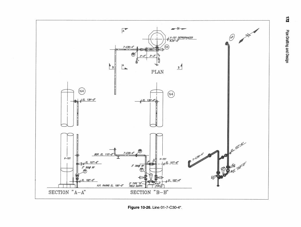
Figure 10-26. Line 01-7-C30-4".

Figure 10-27. Line 01-9-C30-4".

Figure 10-28. Line 01-10-A15-6" IH.

Figure 10-29. Line 01-11-A15-6" IH.

176 Pipe Drafting and Design
reheating. Both lines 01-10-A15-6" IH and 01-11-A15-6" down 9'-07/i6" and turns west, then up into a block valveIH are 6" lines that branch from an 8" header. To deter- aligned with nozzle B. See Figures 10-32 and 10-33 formine the type of branch connection to be made, we must plan and elevation views of lines 01-14-A15-6" and 01-follow piping specification A15. A15 mandates a stub-in 15-A15-6".must be used to make the branch connection on these Line 01-16-C30-2" is a short drain line dropping out oflines. Notice these are liquid lines. The typical procedure the bottom of V-102. This 2" line is attached to nozzle N3for branching lines with a liquid commodity is to branch and drops straight below the nozzle into a drain funnel. Aoff of the bottom of the rack headers. If these lines con- block valve is located at centerline elevation 104'-6". Itstained steam, we would rise off the top of the header pipe handwheel is oriented to the east (see Figure 10-34).to avoid getting condensate in the line. The level gauges and level controllers depicted in
As shown in Figure 10-30, line 01-12-C30-4" rises fit- Figures 10-35 and 10-36 are mounted on a bridle attachedting make-up off the top of V-102 from nozzle N4 with an to vessels E-101 and V-102 respectively. The level gaugeelbow turning west. Another elbow turning down routes and level controller are installed so an operator can easilythe pipe through a control station. The control station is monitor and control the normal liquid level of each ves-parallel to the centerline of V-102, traveling north/south. sel The normai liquid ievel of V-102, the overhead accu-See Figure 10-27 for the measurements required to lay muiator, is typically the centerline of the vessel. Theout the control station. The south end to the control sta- normal liquid levd of E_101 the kettle reboiler? is usually
tion rises to a centerline elevation of 110'-2W and turns one.half the weir height. The weir is a vertical platesouth. A dummy support is required to support this south inside the kettle reboiler that serves as a dam to keep the
run from a horizontal strut in the pipe rack. For further mbe bundle submerged under liquid As the liquid level
explanation of dummy support refer to Chapter 11. From increaseS5 the excess liquid will flow over the weir and be
the dummy support 01-12-C30-4" turns up, then south drawn Qut ̂ h nozzle £ which {s ̂ 01_9_C30_4"again and drops into the 8 fuel gas line in the pipe rack. Procedure 9. Platform, ladder, and cage iayouts
Line 01-13-A-15-6 , shown in Figure 10-31, is D f , . w , ,fc n , ' r Reference drawing: Vendor drawings
designed to transport waste gases from V-102 to the off- „„ iU . , A . ^ A T » r *• *u. „ , T . «, ^ * ^ ^» • «- , <• Whether using manual or AutoCAD applications, the
site flare stack. Line 01-13-A-15-6 rises off the top of . , , . ,. . f ., , ... , , ,. _ _ T , , _ T _ . , , size and location dimensions tor the platforms, ladders,V-102. It begins at nozzle N5 with a gate valve and a , , , . , , ,, ,. . , ,^mr ™ A 7 ^ i A» -,™_u • , j ^// -, rr^ , and cages are established from dimensions provided onPSV. PSV-2 has a 4"-300# inlet and a 6"-150# outlet. . A A • f w im c- m £ A m ™-ru r»cw . .u .1.1- *u u -.A A the vendor drawings for V-101. Figures 10-37 and 10-38The PSV routes the outlet line south, where it drops down . , t ~. . _ , T . _ . . ... , _ .. u . , .. H A ^ A ^ T ^ C U • * i * * TU provide an enlarged view of V-101 describing platforms 1to be supported on the 110-0 TOS horizontal strut. The , „ . , T T 1 . . - t f - i,. ^ tU . , IT • * *u ^ -c^ o/'n and 2, respectively. Use dimensions provided in these fig-Ime truns south again and rolls into the top of the 8 flare , , , /. , i , , , T -, /T,, , ^ /ICQ i * 4.u ^ T-i- off a u j *u ures to place the platforms, ladders, and cages on V-101header at a 45 angle to the east. The 8 flare header then . . . r . e
, ff .. . ., „ . , in your piping arrangement drawing,travels offsite to the flare stack. J v * & & &
Lines 01-14-A15-6" and 01-15-A15-6" are cooling Procedures 10-15: Placement of line numbers, call-water return and supply lines, respectively. They are used outs> coordinates, and dimensionsto circulate the cooling water between E-102 and the Reference drawing: Flow diagram, pipe line list, joboffsite cooling tower. Line 01-14-A15-6" is the cooling specificationswater return line. This pipe will circulate the cooling Key information about a piping facility is not alwayswater that has been heated in E-101 back to the depicted graphically. Some information must be commu-cooling tower to reduce its temperature. 01-14-A15-6" nicated in written form. Certain components of a drawingrises off the top of E-102 at nozzle B with a gate valve such as dimensions, coordinates, elevations, line num-whose handwheel is oriented to the west. After a short bers, fitting and equipment callouts, and design and fabri-vertical run out of the valve, the line turns east then south cation notes can only be represented as writtenfitting make-up. The line travels below the pipe rack and information. The arrangement of information and refer-turns up into the cooling water return header. ence notes on an arrangement drawing usually requires
Line 01-15-A15-6" is the cooling water supply line. It preplanning and proper placement to achieve a goodroutes water that has been cooled in the cooling tower sense of balance on the drawing. This information mustback to E-102. This line drops out of the bottom of the be arranged logically and in a clear legible manner,cooling water supply line in the pipe rack and turns north. Therefore, interferences among reference notes, dimen-When the pipe aligns with nozzle A of E-102, it drops sioning, and object line work must be kept to a minimum.

Figure 10-30. Line 01-12-C30-4".

Figure 10-31. Line 01-13-A15-6".

Figure 10-32. Line 01-14-A15-6".

Figure 10-33. Line 01-15-A15-6".

Figure 10-34. Line 01-16-C30-2".

Figure 10-35. Briddle attachments for E-101.

Figure 10-36. Briddle attachments for V-102.

Figure 10-37. Platform No. 1.

Figure 10-38. Platform No. 2.

186 Pipe Drafting and Design
The following items must be included on piping NOTE: For clarity and neatness, group similararrangement drawings: callouts together in one common location where pos-
sible (see Chapter 11, Figure 11-2).• Completed title block information. • Identification for any miscellaneous items. Locate• North arrow. Place the north arrow in the upper right and describe as required.
corner of the drawing. It should point up or toward AS a general rule, drawing notes and callouts are drawnthe right. .125" tall. When the drawing is created full scale, as with
• Coordinates for match lines, area limits, battery lim- AutoCAD, text height should be a minimum of 4" tall,its, equipment, and structural support foundations, When plotted to 3/8" = 1 '-0" scale, the result would be textall pump suction and discharge nozzles. .125" tall. All notes should be read from the bottom of the
• Labels for angular degrees of orientation (30°, 45°, drawing. Information such as coordinates for match lines,etc.) to indicate orientation of all vertical vessel area limits, battery limits, line numbers, equipment call-nozzles, outs, coordinates, and elevations should be labeled paral-
• Tag numbers (Nl, N2, N3, etc.) for all nozzles on lei to the item to which they apply. This may result inequipment that corresponds to the vessel outline notes being read from the bottom or the right side of thedrawings, equipment vendor drawings, and nozzle drawing.schedule.
• Show Equipment item numbers and title information. ...«.,-. ~DIMENSIONING
NOTE: To avoid congestion on drawing, extendcenterlines away from equipment and provide equip- Developing drawings with a high degree of dimen-ment description and coordinates in an open area of sional accuracy is of primary importance. Good dimen-the drawing. sional arrangement and placement enhances a drawing'sT , , „ „ . ,. .. . _ „ . . _ . effectiveness. Clear, concise, well-placed dimensions not
• Labels for all pipelines with the following information: , „ ^ n iU , ^ . , . , ,.f, r ° only reflect a well-thought-out drawing, they simplifyLine number . . , . , . . . , , . , ,„, ,. . communication, which minimizes checking and reducesFlow direction . . .
, . , , , , . , drawing revisions.Insulation symbol and thicknessSteam, heat, or electrical tracing if required . . _
• A reference note somewhere within the area limits of Dimensionmg Guidelinesthe piping plan drawing to indicate the finished grade „„ , . ,. . , . . u, . , . - . , . When placing dimensions on a drawing, either manu-or high point of paving elevation. n -*u A T ^ A T * i *u f n • -A r, 7,. r & . , , . , „ ally °r wim AutoCAD, apply the following guidelines to
• Label for all instrumentation per the mechanical flow . . ., f., r .. , , . ^^ maximize the use of the limited space on a drawing. Gen-diagram. A l l instrumentation should b e accounted , , . • • . , , - • i j6 . eral dimensioning guidelines include:for one time in either the plan view or section view.Use ¥2" diameter instrument bubble. • Avoid duplication of information. Do not repeat
• Label for the top of platform (TOP) elevation on dimensions or notes in each view of a piece of equip-plan drawing. ment.
• Reference notes to describe the following: • Dimensions on plan drawings are to be placed withinPiping specialty items the drawing's limits, i.e., match lines, drawing limits,Reducers and reducing tees area limits, battery limits, etc.Out of spec flanges • Dimension lines should be in a continuous string.Any nonstandard item not covered in piping spec Avoid staggered or offset dimensions.Vessel davits • Group dimensions outside of a detailed area, whereChain operators for valve handwheels possible. Avoid crossing elements of the drawingPipe guides, supports, anchors, hangers with dimension or extension lines.
• Cutting plane callouts that identify the name and • Avoid placing dimensions between coordinates,direction of the section or elevation to be drawn. • Place dimensions for horizontal lengths on a plan
• Labels for lines running through a pipe rack to spec- drawing. Dimensions for vertical lengths should beify the commodities they contain. shown on sections or elevations.

Piping Arrangement Drawings, Sections, and Elevations 187
• Dimension all piping from centerline to centerline, PIPING SECTIONS AND ELEVATIONS:centerline to face of flange, or face of flange to face WHAT ARE THEY?of flange; do not dimension to welds.
• When required, include gasket thickness in dimen- . , , , . , ,T ,. , , . , . n As previously mentioned, plan view drawings, such as
sions. Indicate gasket location relative to flange ,, f . * j • - ^ u - * i. , , , fc the piping arrangement drawing, provide horizontalextension lines with gasket symbol. ,. . ° , . ° U1. , f . , . „ . , . , , , , , .,& J dimensions that establish a facility s width and depth
• Provide spacing dimensions for lines in a pipe rack. measurements. An occasionai note Or callout is the onlyDo not place a continuous string of dimensions reference to height measurements found on plan draw-across a pipe rack if pipe rack column coordinates ings TQ supply more detailed information on height mea.
P ' surements, drawings called sections and elevations are• Indicate TOS or BOP elevation of lines in the pipe developed. Height is the most important dimension on
ra section and elevation drawings. Although these two terms• Dimensioning should be minimal. Provide only those have come to have synonymous meanings they are con-
dimensions, coordinates, and elevations required to ceptually different.draw and check piping isometrics or spools. Avoid The word eievation has a literal meaning of "heightreferral to other drawings such as vessel drawings, above sea level" Both sections and elevations providevendor drawings, plot plan, etc. height measurements from an object to the ground
• Show all angular offsets. Indicate degree of offset (grade). The primary difference is that elevation drawingsand plane direction (horizontal or vertical). provide a view of the exterior features of a facility, while
section drawings represent interior components of a facil-Procedure 16: Checking your work ity that may not be visible from an exterior viewpoint.Reference drawing: All available information and Comparing this to the features of a house, an elevation
drawings represents what the house looks like from the street, whileNow that the drawing is complete, it must be reviewed a section might show how the furniture in a room is
carefully. A blueprint or plotted copy of the drawing will arranged, what type of wallpaper is on the walls, howbe required. If the drawing was created manually on vel- many pictures are hanging on the walls, or how muchlum, mylar, or other reproducible medium, a blueprint attic space is provided above the ceiling,must be obtained. If the drawing was developed on a com-puter, a copy of the drawing must be plotted. Although Elevation Typesthe drawing will be thoroughly checked by your instructoror supervisor for completeness and correctness, a drafter Section and elevation drawings are the standard onshould always review the drawing to check for any errors, which vertical measurements for foundations, platforms,deletions, or inaccuracies. It may be necessary to system- steel supports, nozzles, and centerlines for equipment andatically review the layout procedure in one's mind to pipe are shown. As mentioned in Chapter 9, Coordinatesduplicate the sequences used to develop the drawing. and Elevations, the ground, or grade, is often given an
Equipment location and size should be verified. Fitting arbitrary value called a datum elevation. Since the use ofand flange dimensions must be confirmed and valve the exact height above sea level dimension is not practi-handwheel orientations must be reviewed. It is also the cal, a datum elevation of lOO'-O" is typically used. Alldrafter's responsibility to assure the drawing was devel- height dimensions are measured from this 100'-0" settingoped in accordance to any and all client or company spec- and are assigned elevation names to describe their typeifications and governing federal regulations. and location. Elevation names for items above grade can
Procedure 17: Drawing release appear in various forms, such as centerline (<L), top ofOnce you have checked and corrected your drawing, it steel (TOS), top of concrete (TOC), bottom of pipe
is customary to indicate the "Completed Date" in the (BOP), or face of flange (EOF or F/F). Elevation namesdrawing title block. Some companies may also require for items below grade are referred to as invert (INV) ele-that a drafter initial the drawing as an affirmation this is vations. The obvious need for the drawing of sections andhis or her work. Run a new blueprint or plot a new copy elevations is to show piping tie-ins to equipment, calcu-of the drawing to provide to your instructor or supervisor. late lengths for vertical piping runs, check for interfer-The drafter may also elect to make an additional copy of ences, make sure lines are properly supported, verifythe drawing to use as future reference. worker and operator access clearances, and establish

188 Pipe Drafting and Design
sufficient overhead clearance required for equipmentinstallation, maintenance, or removal.
Where to Begin?
Sections and elevations come from the piping arrange-ment drawing. Once buildings, equipment, and structuralsupport foundations have been established and pipe, fit-tings, valves, and instrumentation have been representedon the plan view drawing, some indication of what todraw is needed. The cutting plane callout is such an indi-cator. The cutting plane callout resembles a large letter Lwith an arrowhead on one end. The direction the arrow-head points indicates the direction from which the facilityis being viewed. This point of view is the direction fromwhich the section or elevation view is drawn. See Figure10-39 for the use of cutting plane callouts. Notice thecallout is labeled to make referencing between the planand section or elevation views possible.
Depending on the direction from which the facility isviewed, only one horizontal dimension, either width ordepth, is required to locate equipment, foundations, piperacks, etc. on an elevation drawing. This is unlike planview drawings that require two intersecting coordinates tolocate items. Coordinates for match lines, area limits, andbattery limits taken from the piping arrangement drawingare used to establish boundaries on the right and left sidesof section and elevation drawings. With only one locatingcoordinate, equipment can be positioned from the rightor left drawing boundaries. It is recommended that all
Figure 10-39. Cutting plane callouts.
locating measurements be made from either the rightboundary or left boundary to avoid misplacement ofequipment and other components. Figure 10-40 showshow alignment of the plan and elevation views can makecoordinate location quicker by projecting width measure-ments from the plan view down into the elevation view.
Vendor drawings are used to establish sizes of equip-ment. Nozzle schedules and dimensioning charts providelocation, size, and pound ratings for equipment nozzlesand their mating flanges. Pipe routings, fitting rotations,and handwheel orientations on the arrangement drawingsare interpreted and rendered accordingly on the elevation.Although fitting, flange, and valve symbols are the samefor plans, sections, and elevations, the rotation and orien-tation of the symbols will vary. Representation of anelbow that turns down on a piping arrangement drawingwill be drawn differently when viewed from above thanwhen viewed from the side as in an elevation drawing.
DETAIL DRAWINGS
Although a simple note or callout can be sufficient inconveying information to a reader, an actual drawing rep-resentation will provide much more detailed information.One case in point is the TOS callout. Known to mean topof steel, this note, and others like it, is the only way of rep-resenting height on a plan view drawing. But on a sectionor elevation drawing, the actual structural steel membercan be drawn to provide a graphical representation to thereader. By rendering, height measurements become easilyrecognizable. Headroom clearances, pipe support spacing,and possible interferences become self-evident. Figure10-41 shows a typical elevation of the piping facility.
The following guidelines should be used when placingcallouts on section or elevation drawings;
• Provide top of steel (TOS) elevations of all pipe sup-ports.
• Include centerline elevations of exchangers and hori-zontal vessels.
• Specify top of concrete (TOC) or grout elevations forall equipment foundations.
• Provide centerline elevations of horizontal nozzleson equipment, including piping and instrumentationnozzle connections.
• Label face of flange elevations for nozzles attachedto the top or bottom of vertical vessels, exchangers,and suction and discharge nozzles on pumps, tur-bines, and compressors.

Figure 10-40. Projection of coordinates.

Figure 10-41. Elevation view.

Piping Arrangement Drawings, Sections, and Elevations 191
• Indicate high point of finished grade (datum • Dimension from lines running at one elevation toelevation). lines running at a different elevation within pipe
• Mark top of grating or plate on platforms. racks or other areas.• Include bottom of pipe (BOP) elevation for pipelines • Dimension to the center of a valve, except with small
on shoes. bore screwed or socket-weld valves.• Provide centerline elevation of relief valves. • Dimension piping from electrical cable trays, con-
duit, or instrument tray runs.The following list contains some DONTS relating to • Dimension internal equipment piping to external
the dimensioning of plan, elevation, or section drawings. piping.• Dimension piping from outlines of buildings, struc-
DO NOT tures, or equipment.• Dimension "fitting make-up" installations.
• Dimension from underground lines to aboveground • Dimension the lengths of standard piping compo-lines. nents such as elbows, tees, reducers, etc.

192 Pipe Drafting and Design
CHAPTER 10 REVIEW QUIZ
1. What is a piping arrangement drawing?
2. What is a nozzle schedule?
3. Name five reference drawings or documents needed by a piping designer to lay out the piping arrangement drawing.
4. What is the typical scale used to create manual piping drawings?
5. What is the typical scale used to create CAD piping drawings?
6. Which drawing is used as a reference drawing when locating centerlines for pipe racks and equipment foundations?
7. What is the standard height of text used on piping drawings?
8. Explain the difference between section and elevation views.
9. Define datum elevation.
10. What is the most important measurement shown on section or elevation drawings?

Piping Arrangement Drawings, Sections, and Elevations 193
EXERCISES: PLANS, ELEVATIONS, AND SECTIONS
Chapter 10 Drawing Exercises
Exercise 10-1. Using the layout procedures discussedin this chapter, develop the piping arrangement drawingof Unit-01 as shown in Figure 10-1.
Exercise 10-2. Render the elevation view of Unit-01 asshown in Figure 10-41.

Standard PipingDetails
Any project having the complexity of a piping facilitywill undoubtedly have many components that are usedrepeatedly throughout the facility. In an attempt to reducethe volume of drawings produced, many companies haveinitiated the use of standard piping details. The standardpiping detail is a drawing that depicts an item or itemsthat are used with such frequency and having such con-sistency in their installation procedure that a single draw-ing can be created and duplicated for use to representtheir installation in almost every situation. Situations inwhich standard piping details are most likely to be usedare for the support, anchoring, guiding, and spacing ofpipe. This chapter discusses the methods and devicesused in these applications.
PIPE RACK SPACING
Arrangement and positioning are important factors inthe layout of a piping facility. Space is limited. Area andboundary limits force conservation of space. Arrangingequipment throughout the unit in an orderly and sequen-tial fashion is a necessity. Therefore, proper spacing andarrangement of pipe in the pipe rack requires specialattention. A pipe rack has a defined width; therefore,working within the allotted space makes spacing crucial.Not only must pipe be arranged to take up a minimumamount of space, but allowances should be made for anypipe that might be added in the future.
Line spacing dimensions are based on a clearance of1" between the outside diameter of the largest flange andthe outside diameter of the adjacent pipe. The minimumspacing between any two lines is 4". If either of the linesis insulated, the thickness of the insulation must beadded. When lines are placed adjacent to a wall, column,building, or other structure, a minimum clearance of2'-0" is required from the outside diameter of a flange.Pipes having orifice flanges also require a minimumclearance of 2'-0" on either side of the pipe. Figure 11-1shows the requirements for establishing the minimumclearances for line spacing.
The line spacing chart shown in Table 11-1 providesthe minimum clearances for pipe without insulation.
DRAWING PIPE IN THE RACK
When representing pipe in a pipe rack, the carefularrangement and organization of names, dimensions, andline numbers will make the drawing easier to read. Figure11-2 shows a pipe rack that has been well organized.Notice how the alignment of notes, dimensions, and othercallouts makes the drawing easy to read.
The following guidelines will help you organize yourdrawing:
1. Keep flow arrows the same size and aligned.2. Line numbers should be left justified when possible.3. Pipe commodity should be identified on utility lines
only.4. Line spacing dimensions should align across the
pipe rack from one pipe support column to the other.This allows coordinates for each pipe to be calcu-lated since each pipe support column is positionedusing a coordinate.
BUILDING, WALL, COLUMN, OR STRUCTURE
Figure 11-1. Line spacing clearance requirements.
194

Standard Piping Details 195
Table 11-1Line spacing chart.
PIPE FLEXIBILITY w^ resu^ in its interference with an adjacent pipe, linespacing will have to be increased. If the normal expan-sion of a pipe will not result in interference, line spacing
A major concern when arranging pipe in a rack is the will not be affected. Remember, space in the rack is lim-amount of expansion and, to an extent, contraction that ited. Over spacing must be avoided. Figure 11-3 pro-occurs when a cold pipe is heated to its normal operat- vides two illustrations where additional line spacinging temperature. Because the dimensions provided in the may be required.line spacing chart do not account for expansion of a pipe The interference occurring at point 1 is a result of lin-during the start-up of a unit, consideration must be given ear expansion. Lines 103 and 104 have similar spacing into the amount of expansion a pipe will undergo as its the rack. Both pipes drop out of the rack and rest on atemperature begins to rise. If the expansion of a pipe support beam before attaching to a piece of equipment.

196 Pipe Drafting and Design
Figure 11-2. Pipe rack drawing organization.
Using the spacing dimension provided in the line spac- 1. Increase the spacing between the two pipes if theing chart, these lines need 8" for adequate clearance. ends of the pipe where they attach to the pieces ofAdditional calculations indicate line 103 is expanding equipment allow it. If this is not possible, use the2" to the south and line 104 is expanding 2" to the next alternative.north. By adding one-half the OD of line 103 (2V4") 2. Cold spring lines 103 and 104 1". Cold spring is anand one-half the OD of line 104 (21/4") and the 2" of installation technique that requires the length of theexpansion for each pipe, it is obvious an interference pipe that is expanding to be cut short by a distancewill result. To avoid this interference, two alternatives equal to one-half of the length of expansion. In thisare feasible: case 1" for each line.
Figure 11-3. Pipe expansion.

Standard Piping Details 197
When trying to solve the interference problem occur- the deflection of each loop be calculated to avoid inter-ring at point 2, a similar approach can be taken. Either ference.add 1", the amount of expansion, to the line spacing Lines resting on T-supports must be designed carefullydimension or cold spring line 101W to the west and add as well. If a line is positioned too close to the end of a¥2" to the line spacing dimension. support, expansion may push the pipe off the support (see
Figure 11-6). Situations like this may require a cold
PLANNING FOR HEAT EXPANSION spring or a longer r-™P/)0».When multiple lines resting adjacent to one another
turn in the same direction, attention must be given to theHeat expansion can be quite significant on long runs of fact that one line can grow while the other does not In
pipe, especially those in a pipe rack. To absorb the expan- Figure ± 1-7 assume lines 105 and 106 are both expandingsion of pipe in a rack, pipe loops are often incorporated. at the same rate an(j in the same direction. As they bothFigure 11-4 shows a pipe loop as a U-shaped routing of grow? adequate line spacing will be maintained. But whatthe line designed to contain the expansion of the pipe. if iine 106 was a cold line and did not grow at the sameLoops are typically located near the midpoint of a long rate as line 105? Expansion from line 105 would causerun of pipe. Expansion will cause the two ends of the pipe interference with 106. To avoid this, the line spacingto grow toward one another resulting in the distortion of dimensions X and Y in Figure 11-7, must be calculated tothe loop as shown in Figure 11-5. reflect the conditions of one line being hot and the other
When multiple loops are placed at the same location, cold. Calculations using the hot/cold scenario will guar-as shown in Figure 11-4, adequate line spacing requires antee adequate spacing at all times.
Figure 11-6. Pipe expansion on T-supports.
Figure 11-4. Piping loop. Courtesy Nisseki ChemicalTexas Inc., Bayport, Texas
Figure 11-5. Pipe loop distortion. Figure 11-7. Hot and cold line spacing.

198 Pipe Drafting and Design
PIPE ANCHORS
Expansion is not the only force that can alter the align-ment of a pipe. Vibration, commodity turbulence, andother external forces, such as wind, cause a pipe to move.Often restriction of a pipe's movement becomes necessary.To prevent movement or to control the direction of move-ment pipe anchors are often used. Two types of pipeanchors exist: fixed and directional. Fixed anchors are usedin locations where all movement of a line must be pre-vented. The most common way to anchor a pipe is to weldthe pipe directly to a support or structural member. If thepipe to be anchored is insulated, the pipe shoe is welded tothe structural support. Shoes will be discussed later.
Directional anchors are used to force movement tooccur in one direction while preventing it from occurringin the opposite direction. Directional anchors are oftenused to direct a pipe's movement away from buildings,structures, or pieces of equipment. Figure 11-8 depicts theanchoring of uninsulated pipe.
PIPE INSULATION SHOES
Pipe is often insulated to prevent heat loss or to ensureworker safety. Anchoring lines with insulation requiresspecial preparation. Resting insulated pipe directly onstructural support damages the insulation. To protect insu-lation on pipes 3" and larger pipe shoes are welded to thepipe at the location where it rests on a support.
Attached to the pipe prior to the insulation beinginstalled, shoes are approximately 6" long and are madefrom 3" tall structural T-shapes or 6" wide flanges thathave been cut into two pieces (see Figure 11-9). The pipe
Figure 11-8. Pipe anchors.
can then be elevated off the support without damageoccurring to the insulation. Pipe smaller than 3" typicallyhas insulation thin enough to be cut away from the pipe atthe point where the insulation would rest on a support.Therefore no shoes are required.
PIPE GUIDES
When total restriction of pipe movement is notrequired, pipe guides are used. Pipe guides confine move-ment along the pipe's lineal axis. Used primarily tomaintain proper line spacing in a pipe rack, pipe guidesprevent lateral or sideway movement. Unlike the pipeanchor, which is welded to the pipe and structural sup-port, the guide allows pipe to slide lengthwise betweentwo angle shapes (see Figure 11-10). When a pipe is sup-ported on shoes, the angle shapes are positioned on eitherside of the shoe (see Figure 11-11).
Figure 11-10. Pipe guides.

Figure 11-11. Pipe guides with shoe
Figure 11-12. Field support. Courtesy Nisseki Chemical Figure 11-13. Base support. Courtesy Nisseki ChemicalTexas, Inc., Bayport, Texas. Texas, Inc., Bayport, Texas.
Standard Piping Details 199
FIELD SUPPORTS
Once a pipe drops out of the rack, support must be pro-vided to relieve weight stresses that heavy piping systemscan place on nozzles, weld joints, and other criticalpoints. Nozzles and welded joints are not designed tocarry heavy loads. Extreme loads placed on a nozzlecould result in the nozzle being pulled off the vessel orpiece of equipment. Lateral forces applied to weld jointscould have the same result. Field supports are designed tosupport pipe routed down to grade or anywhere structuralsupport is not provided. Figure 11-12 shows a field sup-port being used to carry the load that would otherwise beplaced directly on a stub-in branch connection.
The base support is a type of field support that rests onthe ground, platform, or other stationary surface and isused to support control stations and other pipes routed nomore than 2'-0" above grade level. As seen in Figure11-13, some base supports are dummy welded to the bot-tom surface of an elbow to provide support. Others are

200 Pipe Drafting and Design
attached by bolting. Although similar in function, base of the pipe's axis thereby allowing it to extend across asupports differ in size, attachment methods, adjustability, horizontal structural support (see Figure 11-15).and load capacity.
When the distance from pipe to grade makes the base HANGER RODSsupport inappropriate, a support fabricated from angleiron or structural channel is used. These supports are gen- Hanger rods are the standard supporting device usederally bolted or welded to structural steel or concrete col- when a pipe, or pipes, must be supported from above,umns. They are typically less than 2'-6" in length and, Hanger rods are suspended from overhead lines or struc-with a load capacity of 500 pounds, are used only on pipe tural supports. Two major styles of hanger rods are used.12" and smaller (see Figure 11-14). One *s designed to support a single pipe and one intended
to support multiple lines. Used on lines up to 24" indiameter, and having a load capacity of 4,800 pounds, the
RUMMY QIIPPflRTQuummi ourrumo single pipe hanger uses a rod and clevis to provide sup-port (see Figure 11-16). The multiple line hanger is often
The dummy support or dummy leg as it is also known called a trapeze. It uses a length of steel angle suspendedis used to support pipe that would not otherwise be sup- by two rods at the ends (see Figure 11-17). The trapezeported due to its short length or change in direction. The can vary from 3'-0" to lO'-O" long from center to center ofdummy leg is a piece of open pipe welded to the outside the rods with the shorter length carrying a maximum loadof an elbow. The piece of open pipe acts as a continuation of up to 4,900 pounds.
Figure 11-15. Dummy suppor
Figure 11-16. Rod and clevis.
Figure 11-17. Trapeze.

SPRING HANGERS
Lines having significant growth, due to expansion, pre-vent the use of a stiff support such as a hanger rod or tra-peze. These lines require the use of spring hangers. Springhangers allow expanding pipes room to grow withoutplacing stress on the supporting rod (see Figure 11-18).
Figure 11-18. Spring hanger. Courtesy NissekiChemical Texas, Inc., Bayport, Texas.
Standard Piping Details 201
PICK-UP PIPE SUPPORTS
In most piping facilities, structural column spacing inthe pipe rack is 25'-0". For large diameter pipe, span-ning this distance poses no problem. Smaller diameterpipes, however, don't have the strength necessary tospan this distance and will sag between supports. Thesesags or pockets can become so severe they can preventcommodity flow. Pick-ups are designed to use the largerpipes to support the smaller pipes. Using a length ofsteel angle attached to the larger diameter pipe withU-bolts allows the small diameter pipes to be supportedat their weakest point (see Figure 11-19). Pick-ups canspan up to lO'-O" and carry a load of 1,200 pounds.
The various guides, supports, and anchors discussedin this chapter play a significant role in the overalldesign of a piping facility. Each one requires specialanalysis and calculations to be properly installed. Mostcompanies have strict guidelines governing the use ofthese items. Only designers with years of experienceshould make decisions on when and where to use thesedevices.
Figure 11-19. Pick-ups.

202 Pipe Drafting and Design
CHAPTER 11 REVIEW QUIZ
1. Why is line spacing critical?
2. What is the minimum spacing between lines?
3. Define cold spring.
4. What is a pipe loopl
5. Name two types of pipe anchors.
6. What is a pipe shoe}
1. Explain the difference between a pipe anchor and a pipe guide.
8. What is the function of a dummy legl
9. Name two types of hanger rods.
10. What are pick-up supports designed to prevent?

Piping Systems
Within every piping facility there are specific piping Boiler Watersystems that perform specialized functions. These sys- Boiler water i§ ̂ piping system ̂ deliyers feed
terns vary in their importance to the overall operation of watgr to ^ steam generating equipment in a facility,the facility and can range from vital to peripheral. These Steam is generated by boilerS5 heaters? even nuclear reac.systems can be complex in design or simple in function. ^ and i§ used ifl a wide yariety Qf piping facm^The systems described in this chapter are examples ofthose commonly found in many piping facilities. Emeraencv Water
Designed specifically for worker safety, emergencyPLANT UTILITIES water systems include eye wash and emergency shower
stations. Emergency shower stations are provided in allEvery piping facility is designed for a definite purpose. areas where maintenance and operational personnel are
Most commonly that purpose is to produce a product that subject to hazardous leaks or spills. Eye wash stations arecan be sold for profit. In order to achieve the intended also provided for situations where physical injury may bepurpose of the facility, certain components are incorpo- caused by chemical sprays or hazardous fumes,rated into its design. Plant utilities are among these. Bydesign they are not the profit-producing product. How- Steam and Condensateever, plant utilities provide services that are essential tothe efficient operation of the facility. Utilities include sys- Steam has a number of uses in various piping facilities,terns such as water, steam, condensate, fuel oil and gas, Made by on-site equipment, steam is relatively inexpen-flares, and air. sive. Many utility companies use steam as their source for
powering huge generators to produce electricity. Multi-Water Systems storied buildings use steam to heat a building's occupied
areas during winter months. Cargo ships use steam asOften taken for granted, water systems play an impor- their primary source of power In petrochemical facilities,
tant part in a piping facility's successful operation. Water steam is used to power the steam turbines used as drivers
systems can include cooling water, boiler water, plant on pumps and compressors.water, utility water, and emergency water. In petrochemical facilities, super-heated steam is also
used as stripping steam. Stripping steam is used in frac-IfOOIing mater donation columns to enhance the effectiveness of the
Cooling water flows through a closed piping system fractionation process. In situations where heat tracing isthat circulates water through various pieces of equip- required, steam is used to maintain constant temperaturesment. Exchangers and condensers require chilled water to and prevent commodities with slow flow characteristicsreduce the temperature of the process commodity. As from freezing. During shutdowns, steam is used as awater circulates through the shell of an exchanger, heat is means of cleaning parts and equipment,transferred from the process commodity to the cooling Condensate is the visible evidence of steam condens-water. To maintain its effectiveness, the cooling water is ing. In its purest form, steam is invisible. Only whenpiped to a cooling tower where the heated water is aer- steam cools and becomes heavy with water vapor is itated to reduce its heat gain. After the heat has been visible. Condensate is undesirable in certain situations soremoved from the cooling water, the chilled water travels it must be removed from steam lines. When moved underback to the exchanger and repeats the process. extreme pressure, condensate can be damaging to
203

204 Pipe Drafting and Design
equipment such as turbine impellers. Condensate is sepa-rated from the steam by traps. Steam traps are placed atpocketed low points and at the dead ends of steam head-ers to collect condensate. Condensate is then piped backto fired equipment where it is converted back into steam.
Fuel Oil and Fuel Gas
These commodities are used as fuel for heat sourcessuch as fired heaters and boilers.
Flare Systems
The most noticeable piece of equipment in use, espe-cially after dark, the flare is where waste gases and vaporsare burned. Flare systems collect gases created duringstart-ups and those released from pressure safety valvesand routes them to the flare stack to be burned. Flarestacks are typically located up-wind of process units andare placed a minimum distance of 200' from the closestpiece of process equipment, storage tanks, or coolingtowers. Figure 12-1 depicts a typical flare stack.
Figure 12-1. Flare stack. Courtesy Nisseki ChemicalTexas, Inc., Bayport, Texas.
Air Systems
Another plant utility that is essential to the operation othe facility is its air system. There are two types of aisystems: utility air and instrument air.
Utility air
Utility air is compressed air piped throughout the facility to power pneumatic tools and equipment. Impacwrenches, grinders, and other pneumatic tools are commonly used during normal plant operations. During timeof a shut-down, scheduled maintenance and repairrequire workers to loosen nuts and bolts that have nobeen removed for quite some time. Power driven tools ar<the only efficient means of timely maintenance.
instrument air
Instrument air is also a compressed air system, but witla much different task. Instrument air is used to operate alpneumatic monitoring and controlling instruments in th<piping facility. Pneumatic instruments such as controvalves, recorders, and indicators require an uninterruptecfeed of air to provide continual monitoring and operational control. Routed through small bore pipe and tubing, the compressed air in an instrument air system habeen dried and purified to remove all moisture and an}airborne particles to prevent damage to the instruments.
CONTROL VALVE MANIFOLDS
Control of the commodity traveling through pipe amequipment and accessibility to the controlling apparatu;are two major concerns in any piping facility. The controvalve manifold addresses both of these concerns. The control valve manifold is a series of valves, fittings, and pipingplaced at grade or platform level that uses an automati<valve to control and monitor the flow of a commoditythrough a piping system. The photograph in Figure 12-^depicts a typical control valve manifold arrangement.
Notice the valves used in Figure 12-2. Four differentypes of valves are used in the typical control valve manifold. The valve in the center of the configuration is th<control valve. It has a globe valve or similar body typ<and uses a pneumatic or hydraulic actuator to automatically regulate the commodity's rate of flow. The valves t(the right and left of the control valve are called blocivalves. Block valves are gate valves that are used to bloclthe flow of the commodity through the control valve during times of repair or replacement.

When the block valves are closed, the commodity canbe controlled manually by the bypass valve. The bypassvalve is either a globe, plug, or ball valve located on thebypass line found above the control valve. The bypassvalve is normally closed but is opened when the blockvalves are closed and flow must be regulated manually.The fourth valve type is the drain valve. It is the smallvalve shown below the left reducer. The drain valve isopened after the block valves have been closed and beforethe bolts have been loosened on the flanges that sandwichthe control valve. The drain allow the commodity trappedbelow the two block valves to be captured and disposed ofwithout a spill occurring.
Control valve manifolds can have various configura-tions depending on the placement of the block valves.Care must be taken to orient the handwheels away fromequipment, aisleways, and other obstructions. Figure 12-3depicts the graphical representation of the control valvemanifold shown in Figure 12-2.
Figure 12-2. Control valve manifold. Courtesy NissekiChemical Texas, Inc., Bay port, Texas.
Piping Systems 205
When drawing the plan view of a control valve mani-fold on a piping arrangement drawing, minimal informa-tion is provided. Figure 12-4 shows the plan view of atypical control valve manifold. Notice only the overalllength and the centerline elevation is provided. An instru-ment bubble is shown to aid in the identification of thecontrol valve. Handwheel orientation of the block valvesmust be shown so representation can be made on isometricdrawings. If, for clearance purposes, handwheels of theblock valves are oriented with an offset angle, the angle ofoffset must be shown on the arrangement drawing.
Figure 12-3. Control valve manifold drawing.
Figure 12-4. Control valve manifolds on arrangemendrawings.

206 Pipe Drafting and Design
UTILITY STATIONS
Organization is essential to quality design. Organizinga piping facility with maintenance in mind is crucial toefficient plant operation. Small independent maintenancecenters called utility stations are located throughout a pip-ing facility. Utility stations provide maintenance andoperational personnel with centralized locations to findwater, air, steam, and occasionally nitrogen. Utility sta-tions are placed throughout a facility in such a manner toallow a utility hose 50'-0" long to cover designated areas.A typical utility station is shown in Figure 12-5.
Water and steam are typically found only at utility sta-tions located at grade level. These utilities are necessaryfor equipment that must be washed or steamed clean.Utility air is a service required at all stations in areaswhere pneumatic power tools are used. Manways are
Figure 12-5. Utility station. Courtesy Nisseki ChemicalTexas, Inc., Bayport, Texas.
located at the higher elevations of vertical vessels. Utilitystations must be positioned so utility hoses can easilyreach them. Nitrogen may be required in specific areaswhere instrument lines must be purged during times ofmaintenance or repair.
Figure 12-6 represents a typical utility station as it mayappear on piping arrangement drawings.
METER RUNS
Developing a piping system that incorporates smoothand consistent flow characteristics is imperative in anypiping facility. The ability to measure the rate of flow of acommodity is necessary at various stages throughout afacility. Rate of flow is simply a measurement of theamount of commodity flowing through a pipe in a speci-fied amount of time. The most common way to achievethis is through a section of pipe referred to as a meter run.A meter run is the name given to a straight run of pipethat uses a set of orifice flanges to measure the rate offlow.
You may recall, orifice flanges have valve taps thatallow monitoring equipment to be attached to record thedifferential pressure of a commodity traveling through anorifice plate (see Figure 12-7).
The critical part of a meter run is the orifice plate. Theorifice plate is a thin, flat, circular piece of metal with ahandle attached. The orifice plate is sandwiched betweentwo orifice flanges. A typical orifice plate is shown in
Figure 12-6. Utility station drawing.

Piping Systems 207
which the orifice flanges are installed. Review the client'sspecifications for the project you are working on to verifythe correct upstream and downstream diameters.
SEWER AND UNDERGROUND PIPING SYSTEMS
Though they are not readily visible, extensive pipingsystems can exist below grade. Some piping systems bytheir very nature must be run underground. Others areplaced there as a matter of convenience. Although theyboth are placed below grade, there is a difference betweenunderground sewer and piping systems. The main differ-ence is that sewer systems are gravity flow and have anorigin that is open to atmosphere, while underground pip-ing systems are closed systems that have a defined andconstant pressure.
Sewer Systems
Underground sewer systems are designed for a numberof commodities. They may include sanitary and raw sew-age lines, storm and firewater drains, or process wasterun-off and oily water sewers. Storm and firewater drain
Figure 12-7. Orifice flanges with valve taps. CourtesyNisseki Chemical Texas, Inc., Bayport, Texas.
Figure 12-8. A small diameter hole is bored through thecenter of the plate approximately 75% of the diameter ofthe pipe. By inserting monitoring equipment into thevalve taps, the rate of flow of the commodity can bemeasured.
To receive the most accurate reading possible, turbu-lence within the pipe must be kept to a minimum. Turbu-lence is created by obstructions from items such asfittings and valves. A smooth, consistent flow is createdby providing a sufficient amount of straight pipe beforeand after the orifice flanges. These upstream and down-stream pipe distances are established by using specificlengths of pipe based on the diameter of the pipe. A rule-of-thumb formula to calculate these lengths is shown inFigure 12-9.
To use the formula shown in Figure 12-9, simply mul-tiply the upstream and downstream diameters times thenominal pipe size. The following is an example to calcu-late the upstream and downstream pipe lengths for a 6"pipe meter run.
Upstream distance = 30 (diameters) x 6" = 180" = 15'-0"
Downstream distance = 6 (diameters) x 6" = 36" = 3'-0"
Again, the formula above is a rule-of-thumb guide. Spe-cific values for upstream and downstream diameters varydepending upon the configuration of the piping system in
Figure 12-8. Orifice plate.
Figure 12-9. Meter run length calculations.

208 Pipe Drafting and Design
lines are often run separately for those systems that will flowing through piping systems that lie below grade havecarry raw sewage and corrosive chemical wastes. Oily minimal corrosive properties or have special corrosionwater sewers collect oily waste and residue from com- allowances established for the pipes through which theypressors, pumps, and other equipment. Each commodity flow. However, the corrosion of external metal surfacesrequires special treatment and therefore must be routed to below ground is also a matter of concern. When andifferent treatment facilities. Because they are gravity exposed metal surface lies in moist or salt-laden soil, gal-flow, these systems are generally fabricated using no pipe vanic corrosion begins to occur. Any of a number of fac-smaller than 4" in diameter. tors may cause a small amount of electrical current to
flow through the soil and the pipe. Where the current dis-Underground Piping Systems charges into the soil, metal is removed from the surface of
the pipe and corrosion occurs. For these undergroundMany lines are placed below the ground that are not metal surfaces, cathodic protection systems are used,
related to sewer systems. These lines may be cooling Cathodic protection employs the use of positively chargedwater lines, firewater systems, product supply lines, and electrodes that neutralize the corrosive effects of nega-others. To prevent frequent line replacement, commodities tively charged particles in the earth.

Piping Systems 209
CHAPTER 12 REVIEW QUIZ
1. What are plant utilities?
2. Name five water systems that can be found in a piping facility.
3. Define super-heated steam.
4. What is a steam trap?
5. What is the minimum distance a flare stack can be installed next to other pieces of equipment?
6. Explain the difference between utility air and instrument air.
7. What is the function of a control valve manifold?
8. List the four types of valves used in a control valve manifold.
9. What is a utility station?
10. What is a meter run?

Piping Isometrics
WHAT IS AN ISOMETRIC?
An isometric is a type of three-dimensional drawingknown as a pictorial. Isometrics, or isos as they are com-monly called, are developed using the three primarydimensions of an object: height, width, and depth. Unlikeorthographic drawings that represent the height, width,and depth dimensions in separate views (see Figure 13-1),the isometric combines the three dimensions of the objectinto a single view to provide a pictorial representation(see Figure 13-2). To include the height, width, and depthdimensions in a single view, an isometric must be drawnon axes that measure 30° from the horizontal plane asshown in Figure 13-2.
Figure 13-1. Orthographic views.
Figure 13-2. Isometric view.
Similar to the front, top, and right side views in Figure13-1, piping plans, sections, and elevations offer limitedvisualization of an object, especially when piping compo-nents like fittings, flanges, or valves are incorporated.However, by combining the height, width, and depthdimensions found on plan, section, or elevation views, asingle pictorial view can result in a drawing that providesgreater clarity of the piping configuration. A comparisonof Figure 13-3 with Figure 13-4 shows that a piping iso-metric with piping symbols is obviously clearer and eas-ier to understand than an orthographic view.
The piping isometric is an important drawing thatserves several purposes. It is the primary source for mate-rial take-off of each pipe configuration in the facility.
210

Piping Isometrics 211
Figure 13-3. Piping orthographic views.
Material take-off is the process by which each individualcomponent that makes up a pipe configuration is tabu-lated for purchase or procurement. This means all pipingcomponents (elbows, flanges, nuts, bolts, washers, gas-kets, etc.) must be accounted for so that purchases ofthose items can be made. Isometrics are also used bymany companies as fabrication drawings. Once drawnand properly dimensioned, isometrics are provided to fab-ricators who will build each piping configuration. Afterconfigurations are fabricated, isometrics serve as an aid tothe construction and erection of the facility by providingworkers with the locations of tie-ins, connections, androutings.
Most engineering and construction companies draw apiping isometric of every piping configuration to beinstalled in the facility. Piping isometrics are typicallydrawn single lines no matter the pipe's size, with eachpipe line drawn on a separate sheet of vellum having anisometric grid background. Isometrics are also drawn as aschematic, which means they are not drawn to scale. Iso-metric symbols for fittings, flanges, and valves representall sizes of pipe. No attempt is made to represent a pipe'sactual size or pound rating graphically. This informationis conveyed through the use of callouts and notes placedon the drawing. Although piping isometrics are not drawnto scale, drafters should make every effort to draw themproportionally. Drawing an iso proportionally simplymeans drawing a 10'-0" run of pipe twice as long as a5'-0" length of pipe.
Figure 13-4. Piping isometric view.
To be successful in drawing isometrics, the pipe draftermust be able to interpret the information conveyed by thedrawing symbols for fittings, flanges, or valves used onpiping arrangement, section, and elevation drawings andtransfer that information to the isometric. Notice in Fig-ures 13-3 and 13-4 that the elbow symbols differ in theorthographic views and in the isometric view. Pipingdrawing symbols used on plan, section, or elevation viewsdictate whether a pipe turns left, right, up, or down. Whena pipe on a piping orthographic drawing makes a changein direction, that change must also be reflected on the iso-metric. The point at which the pipe changes direction isreferred to as the turning point (TP). To correctly drawthe isometric representation of a pipe shown on a plan,section, or elevation view, the pipe drafter must beknowledgeable in the use of piping symbols used fororthographic views and the corresponding symbols usedfor isometric views.
To make piping isometrics look uniform, most com-panies use the grid units on the isometric vellum toestablish sizes for fitting, flange, and valve symbols.Remember piping isometrics are not drawn to any par-ticular scale. No matter what size or pound rating fit-tings may be, they are all shown the same size. Figure13-5 shows the size and shape of manually drawn iso-metric symbols for fittings, flanges, and valves relativeto the isometric grid. These symbols are typical ofindustry applications and should be used as a guidewhen drawing piping isometrics.

212 Pipe Drafting and Design
Figure 13-5. Isometric piping symbols.

Piping Isometrics 213
Figure 13-6. Creating isometric piping symbols using AutoCAD.
STEP 1. Drawing setup. Set the SNAP Style to Isometric. STEP 3. Use the ROTATE command to revolve each sym-Set the vertical spacing to .125". Set SNAP TO .0625." bol -30° about its base point.
STEP 2. Draw the desired symbols. Use the BASE com- STEP 4. WBLOCK each symbol using the name associ-mand to place a base point in the location designated in ated with each symbol in Figure 13-7.Figure 13-7.
Isometric symbols drawn with AutoCAD can be orientation of the north arrow on the piping arrangementdeveloped so that a single orientation of the symbol drawing and the north arrow on the piping isometric,can be used in any of the isometric axes. Isometric Figure 13-8 illustrates the relationship between the pipingsymbols can be drawn, rotated, and WBLOCKed for arrangement drawing north arrow and the north arrow onrepeated use in any drawing at any isometric angle. the isometric.Initially symbols for fittings, flanges, or valves are Knowing that a piping arrangement drawing is a plandrawn on the north/south isometric axis, but, before view drawing, a pipe can be determined to be turningthey can be used in the other isometric axes, they must north, south, east, or west when oriented relative to thebe rotated -30° about a base point placed on the center drawing's north arrow. So, if a pipe that has been travel-of the symbol. Use the step-by-step procedures illus- ing north turns down and then east on the arrangementtrated in Figure 13-6 to create isometric piping sym- drawing, it should also be shown to travel north, turnbols using AutoCAD commands. Figure 13-7 shows down, and then east on the isometric drawing (see Figurethe size of the symbols relative to the isometric grid in 13-9).AutoCAD. Most companies prefer to draw piping isometrics
Notice that in Figures 13-1 and 13-2 the height, width, with the north arrow pointing up and to the right. Anand depth dimensions in the orthographic views are alternate position is to draw the north arrow pointing upassigned to the isometric view using point A as a point of and to the left. This is done, however, only in excep-reference. On piping isometrics, establishing a point of tional cases to improve drawing clarity. Figure 13-10reference becomes even more imperative. The complexity uses the configuration from the previous figure to dem-of piping configurations requires a point of reference to onstrate how drawing an isometric with the north arrowestablish orientation between the orthographic and iso- pointing up and to the left will affect the isometric rep-metric views. The north arrow is used as this point of ref- resentation. It is never appropriate to show the northerence. Accurate isometric layout is based on the arrow pointing down.

214 Pipe Drafting and Design
Figure 13-7. AutoCAD isometric piping symbols.

Piping Isometrics 215
Figure 13-7. Continued.

216 Pipe Drafting and Design
Figure 13-8. Orthographic and isometric north arrows
Figure 13-9. Isometric configuration.
Figure 13-10. Alternate north arrow direction.
DRAWING PIPING ISOMETRICS
As an isometric for a particular line is developed, con-stant reference to the piping arrangement, section, or ele-vation drawings is essential. Drawing symbols, callouts,coordinates, and elevations provide detailed informationof the pipe's configuration and routing through the unit.By using this information and the isometric symbols thatcorrespond to the various orthographic drawing symbolsthe pipe drafter can render an isometric describing thepipe's routing. Remember, the isometric must provide adetailed description of the pipe's routing from beginningto end. However, this does not apply to a pipe in a pipe-rack. Piping isometrics are generally drawn to representthe configuration up to and including the first fitting in thepiperack. Use the procedure that follows to render a pip-ing isometric for line 01-2-C30-10".
As shown in Figure 13-11, line 01-2-C30-10" isattached to vessel V-101 at nozzle Nl and nozzle C ofvessel E-101. The line begins at nozzle Nl with a flangeand elbow welded together, fitting make-up. The elbow isoriented toward the north according to the north arrow. Ifline 01-2-C30-10" turns north on the arrangement draw-ing, it must also be shown turning north on the iso. Todetermine the distance a pipe travels in the north direc-tion, or any other horizontal plane, one must establish thelength using two coordinates. If there were a need todetermine the distance a pipe travels in a vertical plane, adrafter would need one of the following: elevation call-outs (found on the plan view drawing) or an elevationdrawing that graphically depicts the amount of verticalchange. Remember, horizontal dimensions are calculatedusing coordinates and vertical dimensions are calculatedusing elevations. Also, recall elevation changes can beshown on the piping arrangement drawing in the form ofcallouts, but the elevation callouts must be adequateenough to determine the length of the pipe traveling in thevertical plane.
After the north run, an elbow turns west and line 01-2-C30-10" travels below vessel E-101. Notice the elbow isalso shown turning west on the iso. When the pipe alignswith the centerline of E-101, another elbow turns the lineup and into nozzle C. Isometric drawing symbols for 90°and 45° elbows are typically shown with square corners,as opposed to the round corners found on arrangementdrawings. However, it is not unusual for some companiesand some CAD software packages to draw elbow sym-bols with round corners. When a pipe is connected to apiece of equipment, nozzles are shown double line. Otherdetails about the equipment are shown in Figure 13-11.

Figure 13-11. Line 01-2-C30-10".

218 Pipe Drafting and Design
They include intersecting coordinates for the center of theequipment, nozzle elevation, and nozzle number.
ISOMETRIC DIMENSIONS, NOTES, AND CALLOUTS
Isometric Dimensions
Length dimensions and informational notes or calloutsare used on isometrics to define the pipe's exact routingthrough a facility. Placement of dimensions on the draw-ing establishes precise lengths between fittings, valves,equipment connections, etc. Information such as coordi-nates, elevations, nozzle projection, pipe size, and poundrating are used to calculate lengths of a run of pipe. Aswith orthographic views, dimensions are placed on iso-metrics that indicate center-to-center, center-to-face, andface-to-face measurements. Figure 13-12 provides dimen-sions for line 01-2-C30-10" using information found onthe plan and elevation views shown in Figure 13-11 andthe equipment vendor drawings found in Chapter 6,Mechanical Equipment.
Figure 13-12. Line 01-2-C30-10" dimensions.
Placing dimensions on a piping isometric withAutoCAD requires the use of the Aligned and Obliqueoptions within the DIMENSION command. Figure 13-13provides two alternatives for placing dimensions on pip-ing isometrics. Dimensions should be aligned with therouted pipe and obliqued as shown in Figure 13-14.
Figure 13-13. Dimensioning alternatives.
Figure 13-14. Aligned and obliqued dimensions.
Isometric Notes and Callouts
Dimensions cannot provide all the informationrequired to properly describe a piping isometric. Notesand callouts placed on the drawing provide significantinformation that may impact the purchase, fabrication,and erection of the configuration. Notes are used todenote pipe size and pound rating of fittings, flanges, andvalves. Notes also specify insulation type and thickness,locations for pipe guides, anchors, or supports, as well asoffset angles. Callouts stipulate instrumentation locationsand size, specification breaks, and fabrication details.Any information that is pertinent to a particular pipe mustbe conveyed on the isometric.

Piping Isometrics 219
Whether dimensioning or placing notes on an iso, all ISOMETRIC OFFSETSwritten information should remain on one of the isometricaxes and inclined to the right. This task becomes a little isometric offsets are formed when a pipe turns at anymore difficult when drawing with AutoCAD. To achieve angle omer man a 9Qo angle Angular offsets can be cre.the proper obliquing and rotation angles required on CAD ated by rolling a 9Qo elbow at any angle or replacing 90°generated isometrics, create the text style outlined in the dbows with 450 dbows The result would be pipes mat no
following procedures. longer travel north, south, east, west, up, or down. Instead
H Step 1. Use the STYLE command to create two dif- jmes wouid run northwest, northeast, southeast, or south-ferent text styles. Use the style names ISOTEXT-1 west Th could also shmt rd Qr downward Several
and ISOTEXT-2 for easy reference. , f • „ • «• ,. u • *r 1 a 1 *J examples of isometnc offsets are shown in Figure 13-16.Step 2. When creating ISOTEXT-1, set the obliquing angle to Dimension lines and callouts are included as a reference.+30°. For ISOTEXT-2 set the obliquing angle to -30°. To establish proper visual orientation, the indication ofStep 3. Depending upon the ISOPLANE being used, set the horizontal (HOR) or vertical (VERT) angles are includedrotation angle in the DTEXT command to the appropriate on all isometric offsets. Forty five degree elbows mustsetting as represented in Figure 13-15. always be labeled on an iso for material take-off purposes.
ISOMETRIC DIMENSIONSAND TEXT CALLOUTS
SET UP TWO TEXT STYLESFOR ISOMETRIC DIMENSIONSAND CALLOUTS.
ISOTEXT-1 SET OBLIQUINGANGLE 30'
ISOTEXT-2 SET OBLIQUINGANGLE -30s
NOTE: AS YOU ENTER THETEXT YOU WILL NEED TOADJUST THE ROTATION ANGLEAS SHOWN.
Figure 13-15. Isometric text.

220 Pipe Drafting and Design
Figure 13-16. Isometric offsets.
Figure 13-16 represents only three of the many offsetsthat can be created using 90° and 45° elbows. Example Aof Figure 13-16 begins with a line traveling north. A 90°elbow is rolled downward and toward the east at a 45°angle. A 45° elbow is required to return the angular offsetto a due easterly direction. This example is labeled as avertical offset because a change in elevation occurs whenthe 90° elbow is turned downward. Example C is also avertical offset, but notice, there is no change in the geo-graphic direction the pipe travels. Here, two 45° elbowsare used to angle the pipe upward while continuing in anortherly direction. Both elbows are 45°, thus, the inclu-sion of the abbreviation TYP, meaning "typical." Exam-ple B demonstrates how horizontal offsets are created. Aswith example C, two 45° elbows are used, but rather thanturning the elbows upward, they are laid on their side anddo not change elevation.
Dimensioning Offsets
With isometric offsets changing a pipe's routing fromone plane to another or from one geographic direction toanother, coordinates and elevations no longer provide allthe dimensions necessary to describe a pipe's total length.However, the use of 90° and 45° elbows to form the off-sets results in a problem that can be easily solved withsimple mathematical formulas. The 90° and 45° elbowsform right triangles. By using Pythagorean's Theoremthat states that the sum of the squares of the two sides isequal to the square of the triangle's hypotenuse, this prob-
^y r\ /•}
lem can be solved. Simply stated, A + B = C . Figure13-17 identifies the sides and angles of a right triangleand their resulting solution formulas.
Figure 13-17. Pythagorean's theorem formulas.
These formulas can be used to solve for the length ofan unknown side when the other two sides are known.They work no matter the degree value of angle X. Someangles seem to be used repeatedly in pipe drafting. Thechart in Figure 13-18 can significantly reduce the amountof time spent on calculating unknown sides of right trian-gles. Use the appropriate decimal value when X is one ofthe provided angles.
As mentioned previously, 90° elbows can be rolled toform any degree of angular offset. To fabricate such a roll,a pipe fitter should be provided with the lengths of thethree sides of the triangle and the degree value of angle X.Solving for an unknown value of X requires some addi-tional trigonometric formulas. Use the formulas providedin Figure 13-19 to solve for the unknown value of angleX. Notice that, relative to X, side A is identified as theside adjacent (SA), side B is identified as the side oppo-site (SO), and side C is identified as the hypotenuse(HYP).

Piping Isometrics 221
Figure 13-18. Decimal equivalents of common angles.
Figure 13-19. Formulas for solving angle X.

222 Pipe Drafting and Design
Multiple Angle Offsets
Elbows are not the only piping components installed inangular positions. Nozzles are placed on vessels in loca-tions where interferences are least likely to occur. As aresult, nozzles oriented at angles of 10°, 20°, 35°, etc., arenot uncommon. When offset or rolled elbows are added,complex math problems often result. Multiple angle con-figurations, such as the one in Figure 13-20, require addi-tional calculations to determine dimensions for its lengthof pipe.
We have already seen how unknown lengths can besolved using right triangle formulas. The key to solvingthe unknown length dimension in Figure 13-20 is theincorporation of right triangles. Remember, drawing spaceis limited. Excessive notes, callouts, and dimensionsare not practical. As with dimensions, the right trianglesare positioned so their lengths establish center-to-centermeasurements: center-of-vessel, to center-of-elbow, tocenterline-of-vessel. The length of the unknown dimen-sion can only be solved by using the limited informationavailable in Figure 13-20. Figure 13-21 demonstrates theway to position three right triangles to solve for theunknown dimension.
Figure 13-20. Multiple angle offsets.
Numbering the triangles will aid in the discussion ofsolving for the sides of each triangle. The unknowndimension is equivalent to the hypotenuse of triangle 3.Begin by determining the known values for each of thetriangles from the information provided in Figure 13-20.Figure 13-22 shows the known values of triangles 1, 2,and 3 placed in their appropriate locations.
The X angle for triangle 1 is shown to be 20°. The6'-11 1/8" dimension is a total of the nozzle projection fornozzle Nl, gasket, 150# flange, and 14" elbow. On trian-gle 2, the 2 '-6" measurement is determined by subtractingthe two west coordinates. The 5'-!" dimension is estab-lished by adding ¥t of the OD of the 14" pipe to the 5'-0"dimension. There are no known dimensions for triangle 3.Remember a minimum of two values must be known inorder to solve the missing lengths or angle of a triangle.By determining the side adjacent (SA) and side opposite(SO) of triangle 3, Pythagorean's theorem can be appliedto find the hypotenuse, the unknown dimension.
Figure 13-21. Locating right triangles.
Figure 13-22. Known values for triangles 1, 2, and 3.

Using the available formulas, the missing lengths oftriangles 1 and 2 must be solved before the sides of trian-gle 3 can be determined. Notice that by subtracting theSA of triangle 2 from the SA of triangle 1, the SO of tri-angle 3 can be determined. Also, adding the SO of trian-gle 1 to the SO of triangle 2 (2'-6") will yield the SA oftriangle 3. The results of these calculations are shown inFigure 13-23. The length of the unknown dimension is5'-1 Me". Angle X of triangle 3 is also an important valueto be determined. This angle establishes the rotation anglefor the 90° elbows. In the fabrication shop, the vessel isnot available to measure the 5'-0" dimension. Knowingthis horizontal angle is the only way the elbows can becorrectly installed.
Rolling Offsets
The culmination of the isometric offset is the rollingoffset. The rolling offset is a compound offset formed byreplacing the two 90° elbows in Figure 13-20 with two45° elbows. The result is an offset that changes elevationand direction simultaneously. Figure 13-24 shows theplan and elevation views of a rolling offset.
Because of its complexity, adequate dimensions cannotbe placed on the orthographic views that fully describethe rolling offset. An isometric is the best place for repre-senting and dimensioning the rolling offset. Rather than ahorizontal or vertical triangle, the rolling offset requiresan isometric box for proper dimensioning. Figure 13-25shows construction of this box and its accompanyingdimensions.
Combining elevational and directional changes com-pounds the difficulty in representing the rolling offset onan isometric drawing. Visualizing directional changes onthe plan view and elevation view simultaneously requirespractice and patience. To aid in this visualization process,some helpful notes have been added to the plan and eleva-tion views of the rolling offset shown in Figure 13-26. Inthe plan view, a box has been drawn through the centersof the two 45° elbows that form the rolling offset. Its cor-ners have been labeled northeast, northwest, southwest,and southeast. The notes in the elevation view identifyupper and lower planes. Remember the plan view showsnorth, south, east, west orientation and the elevation viewdepicts vertical changes in elevation.
The plan view in Figure 13-26 shows that the pipeenters the box from the southwest corner and travels tothe northeast corner where it ends with a flange. Lookingat the elevation view, we can see the pipe beginning onthe upper plane and dropping down to the lower plane. By
Piping Isometrics 223
Figure 13-23. Solutions for triangles 1, 2, and 3.
Figure 13-24. Plan and elevation views of a rollingoffset.
combining the information from these two views, weknow that the pipe begins in the upper southwest cornerand travels down to the lower northeast corner. The result-ing isometric representation is shown in Figure 13-27.

224 Pipe Drafting and Design
Figure 13-25. Rolling offset box.
Figure 13-26. Visualization aids for rolling offsets.
Dimensioning Rolling Offsets
Figure 13-25 identifies the six measurements requiredto dimension a rolling offset. There are four lengthdimensions and two angular dimensions. When a rollingoffset is part of a configuration similar to that shown inFigure 13-28, the lengths of the sides of triangle 3 areapplied to the dimensions of the isometric box (see Figure13-25). Notice the SA of triangle 3 in Figure 13-28 isequal to the RUN of the box, the ROLL of the box isequal to the SO of triangle 3, and angle X of triangle 3 isthe same as the horizontal angle (HOR°).
Figure 13-27. Isometric of rolling offset.
Figure 13-28. Rolling offset with right triangles.
The RISE is determined by subtracting the lower planeelevation from the upper plane elevation. Rolling offsets aretypically fabricated using 45° elbows; therefore, the verticalangle will be 45°. Notice the dimension labeled TRAVELin Figure 13-25. It establishes the true length of the pipefrom the upper plane to lower plane across the box. Thislength is the most difficult to calculate. The values used todetermine its length depend on how the pipe enters and exitsthe isometric box. Figure 13-29 shows the two examples ofthe ways pipes enter and exit the isometric box.
In example A, the pipe enters and exits the isometricbox in the vertical plane. Example B shows the pipe toenter and exit the box in the horizontal plane. When apipe enters and exits in the vertical direction, a 45° angleis formed between the TRAVEL and a dashed line drawndiagonally across the bottom of the box (hypotenuse of

Piping Isometrics 225
triangle 3). When a pipe enters and exits in the horizontal box is equal to the RUN of the box. Once the SA and SOdirection, a 45° angle is formed between the TRAVEL lengths of the 45° right triangle are known, Pythagorean'sand the RUN of the box. Depending on the type, vertical theorem can be used to easily solve the TRAVEL dimen-or horizontal, two different 45° right triangles will be sion of the pipe. Since 45° is a commonly used angle,formed. The TRAVEL of the pipe becomes the hypote- Figure 13-18 can also be used.nuse for either triangle. When solving a right triangle The chart in Figure 13-30 converts inches into deci-whose angle is 45°, the SA and SO will always be equal. mals. Multiplication and division of fractions is simpli-As you can see in example A, the length of the dashed fied using decimal equivalents. This chart is extremelyline is equal to the RISE of the box, and in example B, helpful when performing mathematical calculations on athe dashed line drawn diagonally across the end of the calculator that is limited to decimal input only.
Figure 13-29. Vertical and horizontal pipes relative to the isometric box.
Figure 13-30. Inch to decimal conversion chart.

226 Pipe Drafting and Design
CHAPTER 13 REVIEW QUIZ
1. What is an isometric?
2. Which three dimensions found in orthographic views are required when drawing an isometric?
3. What is material take-off?
4. T F Pipe 14" and above is drawn double line on an isometric.
5. T F Multiple pipes are drawn on a single sheet of isometric grid vellum.
6. T F All isometrics are drawn to scale to show exact size and pound rating.
7. T F Lengths of pipe should be drawn proportionally on an isometric.
8. T F Symbols should be drawn different sizes to reflect a change in pipe size.
9. What is the preferred direction to draw the north arrow on an isometric?
10. What are placed on isometrics to define the pipe's exact routing through a facility?
11. How are isometric offsets formed?
12. To establish proper visual orientation, the indication of or anglesare included on all isometric offsets.
13. State Pythagorean's theorem.
14. What are the names of the three sides of a right triangle?
15. Name the six dimensions required on a rolling offset box.

Piping Isometrics 227
DRAWING EXERCISES
Draw an isometric for each of the following exercises. Show all dimensions, coordinates, equipment callouts, linenumbers, and related information is required. North arrow direction will be assigned.

228 Pipe Drafting and Design

Piping Isometrics
229

230 Pipe Drafting and Design
Solve for the missing dimensions on each of the rolling offset dimensioning boxes shown below. Show all dimensionsin feet/inches, rounded to the nearest i/ie".

CustomizingAutoCAD
Efficiency can be described as the quantity and quality procedures provide a detailed explanation on how com-at which a desired result is attained. Productivity, like- mand aliases can be added to this list,wise, measures the amount of return compared to the NOTE: Significant differences may occur in differentamount of effort. For anyone to be efficient and produc- versions of AutoCAD. Consult your AutoCAD User'stive careful attention must be paid to the techniques and Guide for modifications to your particular version of theprocedures they use to perform their tasks. The inclusion software.of AutoCAD into the design process has made designers Before adding to the existing command aliases list beand drafters more efficient at performing their tasks. aware of the following guidelines:Some simple modifications to AutoCAD techniques alsocan be made to enhance the efficiency and productivity of • Some companies and institutions may already haveAutoCAD users. specific aliases in use. Notify your supervisor or
There is little doubt that computer software programs instructor of any changes made to the ACAD.pgpsuch as AutoCAD have increased the work capacity of file.designers, drafters, and engineers. Simple keyboard com- • Aliases use memory. Be prudent with the number ofmands and mouse strokes are used to perform procedures command names invoked, especially on low mem-that once took many hours to perform by hand. But why ory capacity systems.stop there? If several keyboard commands were compiled • Changes made to the ACAD.pgp file will be auto-into one single command, even greater efficiency can be matically loaded into each new drawing that isrealized. This chapter will provide the reader with quick started or existing drawing that is opened,and simple techniques to realize such efficiency. • Aliases are not restricted to one or two letter names.
But more than two or three letters defeats the pur-pose of creating an alias.
CREATING COMMAND ALIASES • Aliases cannot perform more than one commandstatement.
AutoCAD provides a number of methods to inputuser commands. Screen menus, pull-down menus and steP 1 • Be9in the ACAD.pgp file modification by locating the. ,, . . ., f ., ., , r™ . , subdirectory or folder in which it is stored. In the more recenttoolbars are just three of those methods. The most tra- . < • * / • » A « • * • « ^ • *u 01 mn/^n-r u ^i-,. . , ;, , . , , , , , „ . versions of AutoCAD it is found in the SUPPORT sub-direc-ditional method is through the keyboard. By typing a tory For examp|ej in AutoCAD 2000i the ACAD.pgp f i le iscommand name the user is able to initiate that com- found in the \ACAD2000i\SUPPORT sub-directory.mand. A command alias is a short, quick keyboard
. ., . . . , . , ., . ,... , , NOTE: ACAD2000i is used as an example. If you areinput that is created to replace the traditional and more . ,.„„ , r . _ . ̂ r, ™™-,,. , , . , , A * / - i A r » u using a different release of AutoCAD, replace 20(X)iwidely recognized command name. AutoCAD has sev- . to . r
, / : . , i j • i A i r - 4 . - with your current version,eral of these already in place. A couple of pre-existing J . „ , ,aliases that you may be familiar with are L for LINE , Us? ™"d°WS ̂ ^'° '"8P "and C for CIRCLE. AutoCAD provides an easy \Acad2000i\Supportsubd.rectory.method to shorten the keyboard input required to per- Step 2. Use a text editor such as Microsoft Notepad to loadform any command. th® ACAD.pgp file.
Command aliases are created and saved in a predeter- step 3. Use the scroll bar to move to the beginning of themined section within the ACAD.pgp file. The following Command alias format: section of the ACAD.pgp file.
231

232 Pipe Drafting and Design
Step 4. Position the new alias in its correct alphabetical posi- the scope of the functions they can perform. Further custom-tion. Place a line space below the existing alias to allow the izations such as those described below can make the experi-addition of the new alias. enced AutoCAD user even more efficient and productive.
NOTE: Aliases are not required to be in alphabeticalorder to work properly; however, alphabetizing allows for nciyp Aiirni ionquick and easy verification of duplicate names. Do not Uomu AUI ULIoruse duplicate names.
AutoLISP is a form of the LISP programmingStep 5. Key in the new command alias followed by a comma. language used by programmers to develop unique userTab one time then type in the command name preceded by commands to be used within AutoCAD. These com-an asterisk (*). See the examples that follow. mands5 Qr romines? can rjfflge from the simple tQ quite
Type: complex. They are intended to combine existingE *ERASE AutoCAD functions to form one "super command."
# AutoLISP is used to create commands needed by every-' day users who have specific tasks to perform that
EXX, *EXPLODE ('EXP' is an alternative, but typing a AutoCAD doesn't perform in its "out of the box" state.second X takes less time for inexperi- Thdr tasks can be fl si lified b combining sev-enced typists than searching for the P i A * ^ A T V r •on the kevboard } e AutoCAD functions into one, easy to use, routine.
When these commands or routines are initialized andF, FILLET used wjmjn a drawing they will make an operator more
WARNING: In AutoCAD2000i many commonly used efficient a"d Productive- With AutoCAD R14 came acommands have aliases already created. Do not replace an new visual programming environment for AutoLISPexisting command's alias with a new one unless you are the users, Visual LISP. Former users of AutoLISP willonly operator using your computer. Other operators will be quickly see the improved productivity and ease of usefamiliar with the default aliases and your modifications will be Visual LISP provides. Among its many enhancements,confusing to them. Visual LISP has a color-coded syntax source checker thatStep 6. SAVEihe modified file as the same name. quickly identifies typographical errors. There are also aSteo 7 EXIT the text editor comprehensive set of debugging tools that can search for
extra or missing parentheses. Though LISP routines canStep 8. Load AutoCAD. Open any drawing file and try your fee lex and difficuk tQ . lement m can dnew alias key commands. . r , . , . .
increase your drawing productivity.The list of aliases that follow are common AutoCAD of the two routines we will create, the first is relatively
commands. Some may already exist on your version of simple and will increase your drawing speed when usingAutoCAD. Feel free to add to this list or change the alias keyboard commands. It is divided into two sections. Thecommand as your situation dictates. first section is an alternative to the commands aliases pre-
viously discussed. The second section is a quick methodCO = COPY of inserting flow diagram symbols into a drawing. TheDT = DTSTui - 1̂ 101 second LISP routine is much more complex. By incorpo-
DT = DTEXT rating expressions specific to AutoLISP you will create aED = DDEDIT routine that can be used to quickly draw a horizontal ves-LI = LIST sel and its two head enclosures.
MOD = DDMODIFY One of the drawbacks to the alias commands is thatO = OFFSET they will not perform multiple command statements.
RG = REGEN AutoLISP overcomes this. A multiple command state-RO = ROTATE ment that you may be familiar with is the CHANGE
STR = STRETCH command. CHANGE, when invoked from the keyboard,TR = TRIM requires the operator to select an object, specify whether
you wish to change Properties or Change point, then stip-Creating command aliases helps reduce the time required ulate the type of change to be performed (i.e. Color/Elev/
to input commands at the keyboard. But aliases are limited in Layer/Ltype/ltScale/Lweight/Thickness) prior to the final

Customizing AutoCAD 233
effect being realized. Aliases do not allow multiple (defun c:LE ()parameters to be invoked during the command sequence. (command "LINE" "END")) [draws a LINE seekingA word of caution here, AutoLISP routines override alias the 'From point:' as an ENDpoini]commands. If they both have a common name the (defun c:LM ()AutoLISP routine will be invoked. (command "LINE" "MID")) [draws a LINE seeking
The following step-by-step procedure will explain how the 'From Point:' as a MDpoint}to create your first LISP routine. (defun c:RED ()
(command "COLOR" "RED")) [sets the newStep 1. Use a text editor to begin a new file. COLOR value to RED]
NOTE: To better organize files, all new .Isp files you ere- (defun c:WHITE ()ate should be kept in the same subdirectory as those already (command "COLOR" "WHITE")) [sets the newexisting within AutoCAD. On most versions of AutoCAD COLOR value to WHITE].Isp files are kept in the \SUPPORT subdirectory. (defun c:BLUE ()
_ ..__ . ... , , . , , ^ (command "COLOR" "BLUE")) [sets the newThe LISP routine we will be develop uses defun state- _^T _„ 7 _ r ,.„. ^ r • f T^n. T^TTVT *• ^ £. COLOR value to BLUE]ments. Dejun is an acronym for DEfine FUNction. Defun
statements are keyboard inputs that allow an operator to Step 3. S/WEthe file as PIPELISP.Isp.use short command names to describe longer AutoCAD _. . -.,.-.. . . ...
m , . , .^ Step 4. EX/rthe text editor,command sequences. The letter name used to identifyyour defun statement is the command name that will be Y°u wil1 probably want to test your LISP routine at thistyped at the keyboard as a replacement for the longer time- Unlike the ACAD.pgp file, LISP routines must beAutoCAD command and parameter options. Typing in loaded each time they are to be used in a drawing. Oncethe one or two letter command name saves considerable loaded into a drawing, LISP routines become part of thattime when compared to conventional command sequences. drawing during the time it is the current drawing file. If
you end the drawing and open it at a later time the LISPStep 2. Type the following statements just as they appear. It .. . u , , , T TCD .• , i A . nt• / * *u * i- - i - i -j- x XL. routine must be reloaded. LISP routines can be loaded atis important that you have a good understanding of the , , , , . , , , , , • ,AutoCAD command you're are wanting to initialize so that the keyboard using the following command,no parameter is overlooked. Any new commands you want to g< AutoCAD command Qm
develop can be created in the same manner as the ones th f ll ' •shown below. To help you understand the command being e ° Wl 9-
developed, a short explanation is provided in the brackets Command:(load "PIPELISP")following each statement. Do not include the explanation in press ENTERthe routine you are developing. Remember, type the state-ment just as they are shown. Including all opening, closing, The second part of your LISP routine will incorporateand double parentheses. the flow diagram symbols created in Chapter 1'. As an
NOTE: New versions of AutoCAD have functions that alternative to the AutoCAD Design Center this routinemake these commands seem obsolete. Users of older ver- wil1 exPedite the insertion of symbols that have been pre-sions however may find these commands useful. They are viously mserted mto a Cawing as blocks. Add the follow-intended as samples only. ing de^n statements to the end of your PIPELISP
routine.(defun c:ZE ()
(command "ZOOM" "EXTENTS")) {performs the Step 1. Open the PIPELISP.Isp file using the text editor.ZOOM command with the EXTENTS option. Keep a step 2. Use the scroll bar to move to the end of the file.single line space between each 'defun' statement} step 3 Add ̂ fo||owing defun statements to the end of(defun c:ZP () your P|PEL|SP routine,
(command "ZOOM" "PREVIOUS")) {performs theZOOM command with the PREVIOUS option} (defun c:PUMP ()(defun c:LIT () (command "INSERT" "PUMP")) [Keep a single
(command "LINE" "INT")) [draws a LINE seeking line space between each 'defun' statement.]the 'From point:' as a point of INTersection. LIT was (defun c:EXH ()chosen as the defun name because LI is the command (command "INSERT" "EXH"))alias for the LIST command.} (defun c:HOR ()

234 Pipe Drafting and Design
(command "INSERT" "HOR")) Obviously any name can be given to the defun state-(defun c:VERT () ments to describe the command you want to perform.
(command "INSERT" "VER")) Printing a copy of your routine, once it is complete, may(defun c:GATE () be necessary to prevent the duplication of names on new
(command "INSERT" "GV")) statements you may add later. This printed copy we also(defun c:GLOBE () help you remember the new command names you will be
(command "INSERT" "GBV")) using when inserting the symbols or performing com-(defun c:CONTROL () mands.
(command "INSERT" "CV")) As mentioned previously the second LISP routine is(defun c:CHECK () much more complex than the first. More than just defun
(command "INSERT" "CKV")) statements, it is written using programming expressions(defun c:PSV () specific to AutoLISP that will automatically create a hor-
(command "INSERT" "PSV")) izontal vessel and its two head enclosures, including weld(defun c:ORIFICE () lines. The routine is written in such a manner that the end
(command "INSERT" "OF")) user is allowed to select points within an AutoCAD draw-(defun ciREDUCER () ing that will specify the vessel's location, length, diame-
(command "INSERT" "RED")) ter, and orientation. Once the user has specified the(defun c:BUBBLE () required values the routine will calculate and draw the
(command "INSERT" "IB")) vessel,(defun c:NOZZLE () Follow the steps as indicated below to create the vessel
(command "INSERT" "NOZ")) using AutoLISP language,(defun c:FLOWARO() st 1 y ^ dj b . f.}
(command "INSERT" "FA")) H y
(defun c'CONTBOX () ^teP ^- Type the following statements just as they appear.(command "INSERT" "CB")) Include all opening, closing, and double parentheses,
(princ "Your LISP routine has been loaded!") (defun c: Vessel ()
Step 4. SAVEVne modified file as the same name. (setq s (getpoint "Select starting point on vessel cen-Step 5. EXIT the text editor. terline:\n"))
. , , , , • ,̂, -, (setq a (getangle s "Select second point to establishAny symbol that was created in Chapter 7 can be , . . , ,,NN
jj i rror, • ^ r /ror, -n VCSSCl OnentatlOIKVIl ))added to your LISP routine Before your LISP will prop- . , , , . « « , . ,,. ,, . . ., . . u i * * (setq 1 (getdist Select two points to establish vesselerly insert the appropriate symbol a few more steps must , , e r
u i . A length.be completed. m ,. ^ , ^ .,. ,. . „.
(Tangent to tangent distance). \nSpecify first point. ))Step 1. Make certain all flow diagram symbols have been ( d ( dist ̂ Sdect two ^ to establishcreated on the drawing FLOSYMBL and blocked using the , ,. 4specified names. vessel diameter.
\nSpecify first point."))(setq b (+ a pi))Step 2. Begin or open the drawing into which the flow dia- / , / -y.gram symbols are to be inserted. ^ ^
(setq c (/ d 2))!!eJ?ov;,D
U,Se th! INSERT, C0mmand to insert drawing (setq e (polar sal))FLOSYMBL into the current drawing. ] ,;; . ̂(setq f (/ pi 2))
Step 4. ERASE drawing FLOSYMBL out of the current draw- (seta e (* c 0 7320508))ing. (Inserting and erasing FLOSYMBL will cause the blocks r*of that drawing to become nested within the current drawing.) ^setq h ̂ po ar e ̂ a *> c^
(setq hi (polar s (- a f) c))Step 5. Load your LISP routine if it is not already loaded. / . • / i / /% ^(setq j (polar e (+ a f) g))Command: (load "PIPELISP") (setq j 1 (polar s (- a f) g))Press ENTER (Command \n "PLINE" h "W" "0" "" "A" "CE" j
"A" "-60" "CE"Step 6. Type in the desired symbol name at the commandprompt. Pick the insertion point as needed, establish the (setq k (polar e b (* c 1.2679492))) "A" "-60"appropriate X/Y scale factors, and rotation angle. (setq k (polar e (- a f) c)) "L"

Customizing AutoCAD 235
(setq k (polar k b 1)) "A" "CE" j 1 "A" "-60" "CE" Command: vessel(setq k (polar s a (* c 1.2679492))) "A" "-60" Press ENTER(setq k (polar s (+ a f) c)) "L" _ 0 „ ^ 4 iu' ^ P ®- Respond to tne specified command prompts by(setq k (polar k a 1)) ) selecting the desired points. The horizontal vessel will be(setq m (polar e (- a f) c)) created accordingly,(setq p (polar s (+ a f) c))
(Command "LINE" hm""\n"LINE" hip"") AutoLISP has been enhanced with Visual LISP(Command \n "REGEN")) (VLISP} to increase Productivity- Visual LISP imPle-
ments an integrated development environment (IDE) thatStep 3. SAVE the file as vessel.lsp in the \SUPPORT sub- incorporates several development tools to make thedirectory. AutoLISP programmer's job easier. Among the tools areStep 4. EXIT the text editor. color-coded syntax checker, a compiler and debugger.Step 5. Open or begin an AutoCAD drawing. VLISP represents the next generation of LISP for~* ^ , ., Au i ,o^ • * „ * ,_ . «.« AutoCAD. When the VLISP command is invoked theStep 6. Load the LISP routine as follows. At the AutoCAD ,7. . T ,„„ . . ,. , , T T iU ^̂ ^̂command prompt type the following: Vlsual LISP console 1S ^played. Use the OPEN com-
mand to display an existing AutoLISP routine. At thisCommand: (load"vessel") time the loaded file can be evaluated for accuracy and
Press ENTER. precision. Several debugging features can detect and pin-Step 7. AutoCAD will return to the Command prompt. At the Point anY errors in the routine. Refer to your AutoCADCommand prompt type: documentation for additional information.

236 Pipe Drafting and Design
CHAPTER 14 REVIEW QUIZ
1. Define alias.
2. In what file are command aliases stored? In which subdirectory is the file stored?
3. What is AutoLISP?
4. What is the purpose of a defun statement?
5. In which subdirectory are .Isp files stored?

Three-DimensionalModeling ofPiping Systems
One advancement in piping software that has produced any direction and quickly visualize and understand thea wealth of design and construction possibilities is 3D geometry of its construction. Refer to the model of thecomputer modeling. Though not new, this technology is skid package shown in Figures 15-1 through 15-3.now available to most PC-based CAD users. Previously, Furthermore, to increase clarity, computer software3D computer modeling could be performed only on makes it possible to zoom in close to a selected area ofexpensive mainframe or super-mini computers having the model that may be crowded and confusing. If neces-large amounts of available memory. Continuous improve- sary, the pipe, equipment or structure that lies betweenments in PC hardware and the availability of CAD soft- the viewer and area of concern can be "clipped" orware have made 3DE modeling the preferred method of removed by the modeling software. This makes it possi-producing piping drawings. Some of the available 3D pipe ble to see inside the 3D model and study its hidden fea-modeling software packages are Rebis/AutoPLANT, tures.CADWORKS, PASCE, Caesar, PDS, and PDMS. A Once a 3D model has been developed a virtual tour orcommon question being asked at many companies is "walkthrough" can be created. Walkthroughs hasten cli-whether the benefits of 3D computer modeling of piping ent approval and are used as training videos by plant per-systems actually outweigh the additional effort required sonnel responsible for safely maintaining and operatingto produce them. The consensus of the engineering com- the facility. The improved visualization capabilities alonemunity seems to be "yes" because an increasing number make modeling a piping facility a worthwhile endeavor,of engineering firms are pursuing this method of work The ability to forecast potential design or constructionand a growing lists of clients are demanding it. problems during the modeling phase can result in tremen-
dous time and cost savings as opposed to discovering and
ADVANTAGES OF 3D MODELING solving the problem later at the job site'
One of the advantages of a 3D model over conven- CHECKING FOR INTERFERENCEStional drawings is an improved ability to show clearlywhat occurs during the design phase of a piping facility. Another valuable benefit of 3D computer modeling isChemical plants, refineries and other types of piping the ability to perform interference detection. Buildingfacilities are very complex. Frequently vast numbers, models of complex projects is not something new to pip-sizes and types of pipe, equipment, and other components ing designers. For years plastic models have been builtmust be assembled to complete a project. Even seasoned that can takes hundreds of hours to construct and maypiping designers find it difficult to clearly understand the cost thousands of dollars to produce. One of the mainscope of the project from orthographic views alone. By reasons these models are built is to verify the fit of all theusing a 3D model, designers can view the facility from components in the facility. During the design phase it is
237

Figure 15-1. Model of a piping assembly mounted on a skid. (Model courtesy of Gene Eckert, ECAD, Inc.)

Figure 15-2. Skid model, Plan view.

Figure 15-3. Skid model, Elevation view.

Three-Dimensional Modeling of Piping Systems 241
easy to overlook minor details in something so complex dimensions to the drawings, send them to checkers andas a piping facility. Only by building a physical model can finally release them for construction,the designers verify that there are no interferences A designer can instruct the software to generate plans,between components (i.e., a pipe passing through a steel sections, or elevations in several different drawing for-support, a beam hitting a piece of equipment, etc.). If a mats including single-line, double-line and 3D views withdesign team can detect problems such as these before all hidden lines removed.construction begins, savings in building costs can be Solid modeling is different from wire frame modelingenormous. Each problem area redesigned in the field adds because a solid model can display objects with the hid-substantially to the cost of completing the project. den surfaces removed. On a wire frame, all surfaces are
Piping software that can run clash checking on a 3D visible. Using this solid modeling capability 3D soft-model makes interference detection possible. Interference ware can automatically create projected views of solidsdetection software works by checking the surface of each with all the hidden lines removed (see Figure 15-5component in an assembly against other components. through 15-7). This capability gives the user a powerfulUsually a system is separated into categories such as pip- tool for displaying piping drawings,ing, structure, and equipment. This is easy to do because a3D model is typically developed making use of the soft-ware's layering capability. Piping software will automati- GENERATING ISOMETRIC DRAWINGScally place piping components (fittings, flanges, valves), AUTOMATICALLYsteel supports, and mechanical equipment on their respec-tive layers. It can even segregate piping componentsaccording to pound rating (150, 300, etc.), specification,or material and place them on individual layers. Interfer- 3D modeling software can generate isometric drawingsence checking is performed by checking one layer against of Pi?6 configurations automatically. The isometrics areanother to confirm that no two items are occupying the created from the 3D model and with a few manual touch-exact same space within the facility. Figure 15-4 shows an UPS and additions, are ready for construction issue. Someinterference between a pipe and a structural support. As software packages even have the ability to create isomet-the interference detection program is initiated, certain rics complete with dimensions (see Figure 15-8).software programs will locate the first clash and change ASain' by investing some time and effort in modelingthe color of the two elements that are interfering to a dif- the facility from the start, the designer can reap largeferent color. The software will relocate the area of the returns at the end of the project,model in question to the center of the display and allowthe user to zoom in for a closer look. When multiple inter- COMPUTER-AIDED ENGINEERING OF MODELSferences are detected, with the press of a key the softwarewill proceed to the next problem area, allowing the user toview each area in question in this manner. Some of the Another comP*er task that can be accomplished usingmore sophisticated software packages allow the user to 3D models is that of stress analysis calculations on pipe"fly" around the problem area in real time, viewing it and equiPment- The PiP™g system and its suPPorts can be
from any direction or angle. The ability of computer soft- analyzed both statically and dynamically- Features
ware to help prevent costly construction errors is another include checkin§ for seismic movemef > fl™ inducedreason why 3D modeling is so valuable. vibrations, wind loading and wave loads. By building a
3D model, a designer can use its geometry for other engi-neering design analysis programs.
GENERATING DRAWINGS AUTOMATICALLYFROM A MODEL CHOOSING A MODELING SOFTWARE PACKAGE
Once a 3D model has been built, the geometry of the As with any product in the marketplace, each manufac-piping assembly is clear and unambiguous. The designer ture wants to make their product as attractive and appel-can then use piping software to instruct AutoCAD to ing to potential customers as possible. Software is noautomatically generate drawings that view the model different. Software developers use the most advanced pro-from any direction. The designer can then add notes and gramming languages available to implement all the latest

242 Pipe Drafting and Design
Figure 15-4. Interference detection between a pipe and structural support.
"bells and whistles" into their 3D modeling package to and Isometrics. Rebis also provides several toolbars spe-make it attractive. Different developers write software for cific to each design application (see Figure 15-9).different CAD platforms. Some write for more than one.Selecting the right software involves more than choosingthe one with the best looking sales brochure. To provide a BUILDING A 3D MODEL USING AUTOPLANTbenchmark for determining what features a quality 3Dpiping software package should include we will explore „„ , , ,
f ., , f . f .* r » u - / A * r » T ATVTT" When a new drawing is initialized the dialog boxsome of the base features of the Rebis/AutoPLANT & r .~ shown in Figure 15-10 is displayed. Detailed information
specific to the creation of the 3D model is input into theRebisAlltoPLANT appropriate fields. Information such as Configuration
Units and the location of the modeled area are determinedRebis/AutoPLANT uses AutoCAD as its support by providing X, Y, and Z coordinates. Also requested are
platform. Users of AutoCAD will find it easy to use. the length and width of the proposed model.When loaded, AutoPLANT adds a new item to the pull- The next step is to establish the location of thedown menu list, Rebis. Within the Rebis menu are com- mechanical equipment that will be arranged in the mod-ponents specific to each design application. Design eled area. Using dimensions provided on vendor dataapplications can include Piping, Equipment, Multi-Steel, drawings, measurement parameters are specified for the

Figure 15-5. Plan view of a 3D model. (Courtesy of Rebis, Inc.)

244 Pipe Drafting and Design
Figure 15-6. 3D model, perspective view. (Courtesy of Rebis, Inc.)
various pieces of mechanical equipment used in the Ladders and platforms are added using the dialogdesign. The dialog boxes that follow are specific to cen- boxes shown in Figures 15-18 through 15-20. Informationtrifugal pumps, horizontal heat exchangers, and horizon- supplied on vendor drawings can be used to establishtal and vertical vessels (see Figures 15-11 through 15-14). length, width, orientation, and position of all ladders and
Once the values for each parameter in the dialog box platforms required on the vessels.have been supplied, the user is then prompted to specify After all the required mechanical equipment compo-the equipment's location point, elevation, and orientation nents have been located, the pipe components are addedangle. Each piece of equipment can be systematically through a Drawing Preferences dialog box (see Figureplaced within the model, one-by-one, in a similar manner. 15-21). Within this dialog box all pertinent information
After a piece of equipment is located, additional com- specific to a particular pipe configuration is designated,ponents such as nozzles, ladders, and platforms are Information critical to the accurate modeling of the pipeadded. The dialog boxes shown in Figures 15-15 and is provided. Information such as specification, nominal15-16 are used to place suction and discharge on pumps. pipe size, line number, and insulation thickness. Depend-Figure 15-17 is a representation of the dialog box used to ing on client and/or company design standards,position and orient radial nozzles on horizontal and verti- additional information is also specified. This informa-cal vessels. tion is used to establish the drawing's appearance. Such

Three-Dimensional Modeling of Piping Systems 245
Figure 15-7. Close-up detail of a 3D model. (Courtesy of Rebis, Inc.)
information includes pipe color, layer assignment, draw- are just a few of the many available for inserting pipinging mode (i.e., single-line, double-line, or 3D) and components.surface resolution. Other features within AutoPLANT include automatic
Subsequent to establishing specifications and line isometrics, bills of material and, with an add-on package,size, fittings, flanges, and valves are then added to animated walkthroughs. Developers of other 3D model-equipment nozzles. AutoPLANT's compatibility ing software packages have included features similar tochecking feature prevents accidental misalignment of those found in AutoPLANT. Though some differencesdissimilar specification components. Development of may be apparent, most 3D pipe modeling software pack-each pipe configuration involves little more than ages have many features typical of those found inselecting the desired component then determining its AutoPLANT. Choosing the right 3D modeling softwareconnection point and orientation. Use of the Auto package then becomes a matter of client, company or userRouting feature allows for quick and accurate compo- preference. Figure 15-23 represents a 3D wire framenent placement. The toolbars shown in Figure 15-22 model of Unit 01, which was developed in Chapter 10.

Figure 15-8. Isometric drawing created with AutolSO, from Rebis. (Courtesy Rebis, Inc.)

Three-Dimensional Modeling of Piping Systems 247
Figure 15-9. Rebis menu pull-down and application toolbars.
Figure 15-10. Model setup.

248 Pipe Drafting and Design
Figure 15-11. Centrifugal pump.
Figure 15-12. Horizontal heat exchanger.

Three-Dimensional Modeling of Piping Systems 249
Figure 15-13. Horizontal vessel.
Figure 15-14. Vertical vessel.

250 Pipe Drafting and Design
Figure 15-15. Pump suction nozzles.
Figure 15-16. Pump discharge nozzles.

Three-Dimensional Modeling of Piping Systems 251
Figure 15-17. Radial straight nozzle on equipment.
Figure 15-18. Ladder on vertical vessel.

252 Pipe Drafting and Design
Figure 15-19. Circular platform on vertical vessel.
Figure 15-20. Rectangular platform on horizontal vessel.

Three-Dimensional Modeling of Piping Systems 253
Figure 15-21. Drawing preferences.
Figure 15-22. Flanges, bends, valves and various other toolbars.

Figure 15-23.3-D model of Unit 01.

Appendix ADimensional Data—p. 256
Appendix BReview of Lettering—p. 292
Appendix CAlphabet of Lines—p. 294
Appendix DReview of Math—p. 295
Appendix EUse of the Calculator—p. 296
Appendix FArchitect's Scale—p. 299
255

256 Pipe Drafting and Design Appendix A—Dimensional Data

Dimensional Data 257

258 Pipe Drafting and Design

Dimensional Data 259

260 Pipe Drafting and Design

Dimensional Data 261

262 Pipe Drafting and Design

Dimensional Data 263

264 Pipe Drafting and Design

Dimensional Data 265

266 Pipe Drafting and Design

Dimensional Data 267

268 Pipe Drafting and Design

Dimensional Data 269

270 Pipe Drafting and Design

Dimensional Data 271

272 Pipe Drafting and Design
Commercial Wrought Steel Pipe Data
Nom-inalPipeSize
Inches
%
'/4
%
V2
3/4
1
l!/4
1%
2
2%
3
3%
4
5
6
8
OutsideDiam-eter(D)
I nches
0.405
0.540
0.675
0.840
1.050
1.315
1.660
1.900
2.375
2.875
3.500
4.000
4.500
5.563
6.625
8.625
ScheduleNo.
SeeNote 1
40s80x40s80x40s80x40s80x160. . .XX
40s80x160. . .XX
40s80x160. . .XX
40s80x160. . .XX
40s80x160. . .XX
40s80x160. . .XX
40s80x160. . .XX
40s80x160. . .XX
40s80x40s80x120160. . .XX
40s80x120160. . .XX
40s80x120160. . .XX
203040s6080x100120140. . .XX
160
WallThick-ness(t)
Inches
.068
.095
.088
.119
.091
.126
.109
.147
.187
.294
.113
.154
.218
.308
.133
.179
.250
.358
.140
.191
.250
.382
.145
.200
.281
.400
.154
.218
.343
.436
.203
.276
.375
.552
.216
.300
.438
.600
.226
.318
.237
.337
.438
.531
.674
.258
.375
.500
.625
.750.280.432.562.718.864.250.277.322.406.500.593.718.812.875.906
InsideDiam-eter(d)
Inches
.269
.215
.364
.302
.493
.423
.622
.546
.466
.252
.824
.742
.614
.4341.049.957.815.599
1.3801.2781.160.896
1.6101.5001.3381.1002.0671.9391.6891.5032.4692.3232.1251.7713.0682.9002.6242.3003.5483.3644.0263.8263.6243.4383.1525.0474.8134.5634.3134.0636.0655.7615.5015.1894.8978.1258.0717.9817.8137.6257.4397.1897.0016.8756.813
Areaof
Metal
v(a)SquareInches
.0720
.0925
.1250
.1574
.1670
.2173
.2503
.3200
.3836
.5043
.3326
.4335
.5698
.7180
.4939
.6388
.83651 .0760.6685.8815.1070.534.7995.068.429.885.075.477
2.1902.6561.7042.2542.9454.0282.2283.0164.2055.4662.6803.6783.1744.4075.5956.6218.1014.3006.1127.9539.69611.3405.5818.40510.7013.3215.646.577.268.40
10.4812.7614.9617.8419.9321.3021.97
TransverseInternal Area
SquareInches
.0568
.0364
.1041
.0716
.1910
.1405
.3040
.2340
.1706
.050
.5330
.4330
.2961
.148
.8640
.7190
.5217
.2821.4951.2831.057.6302.0361.7671.406.950
3.3552.9532.2411.7744.7884.2383.5462.4647.3936.6055.4084.1559.8868.88812.7311.5010.319.287.80
20.0118.1916.3514.6112.9728.8926.0723.7721.1518.8451.8551.1650.0347.9445.6643.4640.5938.5037.1236.46
SeeNote 2SquareFeet
.00040
.00025
.00072
.00050
.00133
.00098
.00211
.00163
.00118
.00035
.00371
.00300
.00206
.00103
.00600
.00499
.00362
.00196
.01040
.00891
.00734
.00438
.01414
.01225
.00976
.00660
.02330
.02050
.01556
.01232
.03322
.02942
.02463
.01710
.05130
.04587
.03755
.02885
.06870
.06170
.08840
.07986
.0716
.0645
.0542
.1390
.1263
.1136
.1015
.0901
.2006
.1810
.1650
.1469
.1308
.3601
.3553
.3474
.3329
.3171
.3018
.2819
.2673
.2578
.2532
Momentof
Inertia
(DInches to4th Power
.00106
.00122
.00331
.00377
.00729
.00862
.01709
.02008
.02212
.02424
.03704
.04479
.05269
.05792
.08734
.1056
.1251
.1405
.1947
.2418
.2839
.3411
.3099
.3912
.4824
.5678
.6657
.86791.1621.3111.5301.9242.3532.8713.0173.8945.0325.9934.7886.2807.2339.610
11.6513.2715.2815.1620.6725.7330.0333.6328.1440.4949.6158.9766.3357.7263.3572.4988.73105.7121.3140.5153.7162.0165.9
WeightofPipe
Poundsperfoot
.244
.314
.424
.535
.567
.738
.8501.0871.3001.7141.1301.4731.9402.4401.6782.1712.8403.6592.2722.9963.7645.2142.7173.6314.8626.4083.6525.0227.4409.0295.797.6610.0113.707.5810.2514.3218.589.11
12.5110.7914.9819.0022.5127.5414.6220.7827.1032.9638.5518.9728.5736.4045.3053.1622.3624.7028.5535.6443.3950.8760.6367.7672.4274.69
Weightof
Water
Poundsper footof pipe
.025
.016'.045.031.083.061.132.102.074.022.231.188.128.064.375.312.230.122.649.555.458.273.882.765.608.42 4
1.451.28.97.77
2.071.871.541.073.202.8-62.351.804.293.845.504.984.474.023.388.677.887.096.335.61
12.5111.2910.309.168.1622.4722.1721.7020.7719.7818.8317.5916.6816.1015.80
ExternalSurface
Sq. Ft.per footof pipe
.106
.106
.141
.141
.178
.178
.220
.220
.220
.220
.275
.275
.275
.275
.344
.344
.344
.344
.435
.435
.435
.435
.497
.497
.497
.497
.622
.622
.622
.622
.753
.753
.753
.753
.916
.916
.916
.9161.0471.047.178.178.178.178.178.456.456.456.456.456.734.734
1.7341.7341.7342.2582.2582.2582.2582.2582.2582.2582.2582.2582.258
SectionModulus
(4).00523.00602.01227.01395.02160.02554.04069.04780.05267.05772.07055.08531.10036.11032.1328.1606.1903.2136.2346.2913.3421.4110.3262.4118.5078.5977.5606.7309.979
1.1041.0641.3391.6381.9971.7242.2252.8763.4242.3943.1403.2144.2715.1785.8986.7915.4517.4319.25010.79612.0908.50
12.2214.9817.8120.0213.3914.6916.8120.5824.5128.1432.5835.6537.5638.48
Note 1: The letters s, x, and xx in the column of Schedule Note 2: The values shown in square feet for the TransverseNumbers indicate Standard, Extra Strong, and Double Internal Area also represent the volume in cubic feet perExtra Strong Pipe, respectively. foot of pipe length.
Courtesy of Crane Co.

Dimensional Data 273
Nom-inalr>: »_ .,A Ipfi
Size
I nches
10
12
14
1 C.ib
1 O18
^t\20
24
OutsideDiam-
eter(D)
Inches
10.750
12.75
14.00
16.00
18.00
20.00
24.00
ScheduleNo.
SeeNotel
203040s60x80
1001201401602030. .s40. .X
6080
100120140160102030s40. .X
6080
100120140160
102030s40x6080
100120140160
1020. .s30. .X
406080
100120140160
1020s30x406080
100120140160
1020s. .X
30406080
100120140160
WallThick-
ness(t)
1 nches.250.307.365.500.593.718.843
1.0001.125
.250
.330
.375
.406
.500
.562
.687
.8431.0001.1251.312.250.312.375.438.500.593.750.937
1.0931.2501.406.250.312.375.500.656.843
1.0311.2181.4381.593
.250
.312
.375
.438
.500
.562
.750
.9371.1561.3751.5621.781
.250
.375
.500
.593
.8121.0311.2811.5001.7501.968
.250
.375
.500
.562
.687
.9681.2181.5311.8122.0622.343
InsideDiam-eter(d)
Inches10.25010.13610.0209.7509.5649.3149.0648.750
. 8.50012.25012.09012.00011.93811.75011.62611.37611.06410.75010.50010.12613.50013.37613.25013.12413.00012.81412.50012.12611.81411.50011.18815.50015.37615.25015.00014.68814.31413.93813.56413.12412.81417.50017.37617.25017.12417.00016.87616.50016.12615.68815.25014.87614.43819.50019.25019.00018.81418.37617.93817.43817.00016.50016.06423.50023.25023.00022.87622.62622.06421.56420.93820.37619.87619.314
Areaof
\ ff n+ _|Metal(a)
SquareInches
8.2410.0711.9016.1018.9222.6326.2430.6334.02
9.8212.8714.5815.7719.2421.5226.0331.5336.9141.0847.1410.8013.4216.0518.6621.2124.9831.2238.4544.3250.0755.6312.3715.3818.4124.3531.6240.1448.4856.5665.7872.1013.9417.3420.7624.1727.4930.7940.6450.2361.1771.8180.6690.7515.5123.1230.6336.1548.9561.4475.3387.18
100.33111.49
18.6527.8336.9141.3950.3170.0487.17
108.07126.31142.11159.41
TransverseInternal Area
SquareI nches82.5280.6978.8674.6671.8468.1364.5360.1356.75
117.86114.80113.10111.93108.43106.16101.6496.1490.7686.5980.53
143.14140.52137.88135.28132.73128.96122.72115.49109.62103.8798.31
188.69185.69182.65176.72169.44160.92152.58144.50135.28128.96240.53237.13233.71230.30226.98223.68213.83204.24193.30182.66173.80163.72298.65290.04283.53278.00265.21252.72238.83226.98213.82202.67433.74424.56415.48411.00402.07382.35365.22344.32326.08310.28292.98
SeeNote 2Square
Feet.5731.5603.5475.5185.4989.4732.4481.4176.3941.8185.7972.7854.7773.7528.7372.7058.6677.6303.6013.5592.9940.9758.9575.9394.9217.8956.8522.8020.7612.7213.6827
1.31031.28951.26841.22721.17661.11751.05961.0035.9394.8956
1.67031.64671.62301.59901.57631.55331.48491.41831.34231.26841.20701.13692.07402.01421.96901.93051.84171.75501.65851.57621.48491 .40743.01212.94832.88532.85422.79212.65522.53622.39112.26452.15472.0346
Momentof
Inertia(D
Inches to4th Power
113.7137.4160.7212.0244.8286.1324.2367.8399.3191.8248.4279.3300.3361.5400.4475.1561.6641.6700.5781.1255.3314.4372.8429.1483.8562.3687.3824.4929.6
1027.01117.0383.7473.2562.1731.9932.4
1155.81364.51555.81760.31893.5549.1678.2806.7930.3
1053.21171.51514.71833.02180.02498.12749.03020.0
756.41113.01457.01703.02257.02772.03315.23754.04216.04585.51315.41942.02549.52843.03421.34652.85672.06849.97825.08625.09455.9
Weightof
P .ipe
Poundsperfoot28.0434.2440.4854.7464.3376.9389.20
104.13115.6533.3843.7749.5653.5365.4273.1688.51
107.20125.49133.68160.2736.7145.6854.5763.3772.0984.91
106.13130.73150.67170.22189.1242.0552.3662.5882.77
107.50136.46164.83192.29223.64245.1147.3959.0370.5982.0692.45
104.75138.17170.75207.96244.14274.23308.51
52.7378.60
104.13122.91166.40208.87256.10296.37341.10379.0163.4194.62
125.49140.80171.17238.11296.36367.40429.39483.13541.94
Weightof
\\r 4.WaterPoundsper footof pipe
35.7634.9634.2032.3531.1329.5327.9626.0624.5951.0749.7449.0048.5046.9246.0044.0441.6639.3337.5234.8962.0360.8959.7558.6457.4655.8653.1850.0447.4545.0142.6081.7480.5079.1276.5873.4269.7366.1262.6258.6455.83
104.21102.77101.1899.8498.2796.9392.5788.5083.7679.0775.3270.88
129.42125.67122.87120.46114.92109.51103.3998.3592.6687.74
187.95183.95179.87178.09174.23165.52158.26149.06141.17134.45126.84
ExternalSurface
Sq. Ft.per footof pipe2.8142.8142.8142.8142.8142.8142.8142.8142.8143.3383.3383.3383.3383.3383.3383.3383.3383.3383.3383.3383.6653.6653.6653.6653.6653.6653.6653.6653.6653.6653.6654.1894.1894.1894.1894.1894.1894.1894.1894.1894.1894.7124.7124.7124.7124.7124.7124.7124.7124.7124.7124.7124.7125.2365.2365.2365.2365.2365.2365.2365.2365.2365.2366.2836.2836.2836.2836.2836.2836.2836.2836.2836.2836.283
SectionModulus
(4)21.1525.5729.9039.4345.5453.2260.3268.4374.2930.239.043.847.156.762.874.688.1
100.7109.9122.636.645.053.261.369.180.398.2
117.8132.8146.8159.648.059.270.391.5
116.6144.5170.5194.5220.0236.761.175.589.6
103.4117.0130.1168.3203.8242.3277.6305.5335.675.6
111.3145.7170.4225.7277.1331.5375.5421.7458.5109.6161.9212.5237.0285.1387.7472.8570.8652.1718.9787.9
Courtesy of Crane Co.

274 Pipe Drafting and Design
* See M dimensions for branch height of 42" or 48" full branch tee. All dimensions are in inches.See ANSI B16.9 for cap lengths when wall thicknesses are greater than x-stg. _ , _ , _
Courtesy of Taylor Forge

Dimensional Data 275
FLANGES DIMENSIONS
Courtesy of Taylor Forge

276 Pipe Drafting and Design
FLANGES DIMENSIONS

Dimensional Data 277
Courtesy of Taylor Forge

278 Pipe Drafting and Design
1. Dimensions are in inches. Prices on application. 8. Large diameter flanges.2. Standard bore will be furnished unless otherwise specified. c Minimum bores.3. Socket Weld figs, are not mfd. in 150# type over 24", in 300# and 600# over 3", in 1500# "Facings: 150# and 300# flanges (except Lap Joint) furnished with 1-'/«" raised face, which
over 2'v2", in 400# and 2500# in any size. is included in the thickness and hub length shown, 400# and heavier flanges (except Lap4. Specifications—All Taylor Forge flanges conform to ANSI Std. B16.5 or MSS SP44 as Joint) furnished with %" raised face, which is not included in thickness or hub length dimen-
applicable and to ASTM Spec. A181 (for 150# and 300# flanges) or A105 (for 400# and sions.heavier flanges. "Refer to Taylor Forge Pipeline Catalog 723 for complete listings of MSS-SP44 and API 605
5. Welding bevel standards and tolerances. flanges.6. Pressure—Temperature ratings. • Dimension and blind flange is same as companion flange, however, this is not true for7. Threading details. MSS blind flanges, class 300 or heavier, 26" and larger, which have a greater thickness.
Courtesy of Taylor Forge

Dimensional Data 279
D I A P H R A G M A N D P I S T O N A C T U A T O R S
DIAPHRAGM ACTUATORS
Type 657 direct acting diaphragm actuator.
Courtesy of Fisher Controls

280 Pipe Drafting and Design
VALVE TRIM 750°F and pressure drops up to 150 psi. For very highpressure drops or high temperature conditions, a hard sur-
The term "trim" refers to the internal parts of a valve facing alloy such as Stellite can be used on the wearingbody assembly which come in contact with the controlled parts of the valve plug, seat rings, guide bushings andfluid. Type 316 stainless steel is Fisher's standard trim guide posts. Other alloys such as Monel, Hastelloy "B",material. It is satisfactory for most applications and is Durimet 20 or 440C stainless steel may be selected togenerally recommended for fluid temperatures up to combat individual corrosion and erosion problems.
Courtesy of Fisher Controls

Dimensional Data 281
Courtesy of Fisher Controls

282 Pipe Drafting and Design
ACTUATORS Design "BFC" 12„ ™ o Design "D" 12^e^ I Design "DA" 13
^470 4 Design "DB" & "DBQ" 13T^e472 4 Design "DBA" & "DBAQ" 13*yP '\ <- Design "E" 14I™*™ \ Design "EA" 15TyPe5B
BODIES 5 ^n"GS" 15
BODI£b Design "HS" 16Design "A" Single Port 6 and 7 Design "K" & "KB" 17Design "A" Double Port 8 and 9 Design "Y" (Iron) 17Design "AA" 10 Design "Y" (Steel) 18Design "AC" 10 and 11 Design "YY" (Iron) 18Design "B" 11 Design "YY" (Steel) 19Design "BA" 12 Design "Z" 19Design "BF" 12 Design "ZLA" 19
PROCEDURE
To obtain the overall dimensions of a control Example:valve, add the "D" and "G" body dimensions to the Given: 6" Type 657-A, 150 Ib. RF flanged, double port"E" dimension of the actuator. Dimensions for valve steel body with top and bottom guided valve plug,jodies with a 5" boss head are so indicated and these From the table below, note that a Size 50 or 60 Typedimensions should be combined with one of the fol- 657 actuator is normally supplied with a 6" valve. Dimen-lowing actuators: Size 80 and 87, Types 657 and sion "E" from Page 3 is 28-7/i6". From Page 8, we see that667; Sizes 80, 86, 100 and 130, Type 470; Sizes 80 "G" is 13-s/i6" and "D" is 14-'Vi6". Thus, E + G + D = 28-and 100, Types 472 and 473. Similarly, dimensions 7i6"+ 13-s/i6"+ 14-i5/i6" = 56-u/i6".for valve bodies that can be furnished with a 11A" NOTE: When using a valve plug requiring a top guideboss head are so indicated and these dimensions but not a bottom guide, such as Micro-Form valve plug,should be combined with the dimensions of the Type use dimension "D" under top and bottom guided and513 or the Type 470, Size 23, actuators. dimension "G" under skirt guided.
. . . STANDARD CONSTRUCTIONS . . .SERIES 657 AND 667 DIAPHRAGM ACTUATORS
*Design "GS," "B," and "BA" bodies only. Courtesy of Fisher Controls

Courtesy of Fisher Controls
Dimensional Data 283
ACTUATOR DIMENSIONS
TYPE 657 DIAPHRAGM ACTUATOR TYPE 667 DIAPHRAGM ACTUATOR

284 Pipe Drafting and Design
DESIGN "A" DOUBLE PORT IRON BODIES
PLAIN BONNET
DESIGN "A" DOUBLE PORT STEEL BODIES
Courtesy of Fisher Controls

Dimensional Data 285
DESIGN "A" SINGLE PORT IRON BODIES
DESIGN "A" SINGLE PORT STEEL BODIES
ABOTEVMTIOMS USED ABOVE ISCRO-SCREWED ENDS. RF-RAISED FACE, RTJ-MNO Tr« JOINTFLANOE SPECIFICATION NCFCRENCE: I5O-3OO-4OO-40O La USAS BWS* MMENSIONALLY THE SAME AS 600 LB. RF+ OIMENSIONACLY THE SAME AS 6OO UB. RTJ

286 Pipe Drafting and Design
Courtesy of P
enberthy

Dimensional Data
287
Co
urtesy of P
enb
erthy

288 Pipe Drafting and Design
LINEAR CONVERSION
Fractions of an InchTo Decimals of an Inch and to Millimeters
Courtesy of Crane Co.

Dimensional Data 289
LINEAR CONVERSION
Inches to Millimeters(1 inch = 25.4 millimeters)
In.
01234
56789
1011121314
1516171819
2021222324
2526272829
3031323334
3536373839
4041424344
4546474849
50
0
0.025.450.876.2
101.6
127.0152.4177.8203.2228.6
254.0279.4304.8330.2355.6
381.0406.4431.8457.2482.6
508.0533.4558.8584.2609.6
635.0660.4685.8711.2736.6
762.0787.4812.8S38.2863.6
889.0914.4939.8965.2990.6
1016.01041.41066.81092.21117.6
1143.01168.41193.81219.21244.6
1270.0
Vie
1.627.052.477.8
103.2
128.6154.0179.4204.8230.2
255.6281.0306.4331.8357.2
382.6408.0433.4458.8484.2
509.6535.0560.4585.8611.2
636.6662.0687.4712.8738.2
763.6789.0814.4839.8865.2
890.6916.0941.4966.8992.2
1017.61043.01068.41093.81119.2
1144.61170.01195.41220.81246.2
1271.6
%
3.228.654.079.4
104.8
130.2155.6181.0206.4231.8
257.2282.6308.0333.4358.8
384.2409.6435.0460.4485.8
511.2536.6562.0587.4612.8
638.2663.6689.0714.4739.8
765.2790.6816.0841.4866.8
892.2917.6943.0968.4993.8
1019.21044.61070.01095.41120.8
1146.21171.61197.01222.41247.8
1273.2
Vie
4.830.255.681.0
106.4
131.8157.2182.6208.0233.4
258.8284.2309.6335.0360.4
385.8411.2436.6462.0487.4
512.8538.2563.6589.0614.4
639.8665.2690.6716.0714.4
766.8792.2817.6843.0868.4
893.8919.2944.6970.0995.4
1020.81046.21071.61097.01122.4
1147.81173.21198.61224.01249.4
1274.8
%
6.431.857.282.6
108.0
133.4158.8184.2209.6235.0
260.4285.8311.2336.6362.0
387.4412.8438.2463.6489.0
514.4539.8565.2590.6616.0
641.4666.8692.2717.6743.0
768.4793.8819.2844.6870.0
895.4920.8946.2971.6997.0
1022.41047.81073.21098.61124.0
1149.41174.81200.21225.61251.0
1276.4
Vl6
7.933.358.784.1
109.5
134.9160.3185.7211.1236.5
261.9287.3312.7338.1363.5
388.9414.3439.7465.1490.5
515.9541.3566.7592.1617.5
642.9668.3693.7719.1744.5
769.9795.3820.7846.1871.5
896.9922.3947.7973.1998.5
1023.91049.31074.71100.11125.5
1150.91176.31201.71227.11252.5
1277.9
%
9.534.960.385.7
111.1
136.5161.9187.3212.7238.1
263.5288.9314.3339.7365.1
390.5415.9441.3466.7492.1
517.5542.9568.3593.7619.1
644.5669.9695.3720.7746.1
771.5796.9822.3847.7873.1
898.5923.9949.3974.7
1000.1
1025.51050.91076.31101.71127.1
1152.51177.91203.31228.71254.1
1279.5
Vie
11.136.561.987.3
112.7
138.1163.5188.9214.3239.7
265.1290.5315.9341.3366.7
392.1417.5442.9468.3493.7
519.1544.5569.9595.3620.7
646.1671.5696.9722.3747.7
773.1798.5823.9849.3874.7
900.1925.5950.9976.3
1001.7
1027.11052.51077.91103.31128.7
1154.11179.51204.91230.31255.7
1281.1
%
•12.738.163.588.9
114.3
139.7165.1190.5215.9241.3
266.7292.1317.5342.9368.3
393.7419.1444.5469.9495.3
520.7546.1571.5596.9622.3
647.7673.1698.5723.9749.3
774.7800.1825.5850.9876.3
901.7927.1952.5977.9
1003.3
1028.71054.11079.5U04.91130.3
1155.71181.11206.51231.91257.3
1282.7
*A«
14.339.765.190.5
115.9
141.3166.7192.1217.5242.9
268.3293.7319.1344.5369.9
395.3420.7446.1471.5496.9
522.3547.7573.1598.5623.9
649.3674.7700.1725.5750.9
776.3801.7827.1852.5877.9
903.3928.7954.1979.5
1004.9
1030.31055.71081.11106.51131.9
1157.31182.71208.11233.51258.9
1284.3
%
15.941.366.792.1
117.5
142.9168.3193.7219.1244.5
269.9295.3320.7346.1371.5
396.9422.3447.7473.1498.5
523.9549.3574.7600.1625.5
650.9676.3701.7727.1752.5
777.9803.3828.7854.1879.5
904.9930.3955.7981.1
1006.5
1031.91057.31082.71108.11133.5
1158.91184.31209.71235.11260.5
1285.9
»V4e
17.542.968.393.7
119.1
144.5169.9195.3220.7246.1
271.5296.9322.3347.7373.1
398.5423.9449.3474.7500.1
525.5550.9576.3601.7627.1
652.5677.9703.3728.7754.1
779.5804.9830.3855.7881.1
906.5931.9957.3982.7
1008.1
1033.51058.91084.31109.71135.1
1160.51185.91211.31236.7262.1
1287.5
3/4
19.144.569.995.3
120.7
146.1171.5196.9222.3247.7
273.1298.5323.9349.3374.7
400.1425.5450.9476.3501.7
527.1552.5577.9603.3628.7
654.1679.5704.9730.3755.7
781.1806.5831.9857.3882.7
908.1933.5958.9984.3
1009.7
1035.11060.51085.91111.31136.7
1162.11187.51212.91238.31263.7
1289.1
13/ie
20.646.071.496.8
122.2
147.6173.0198.4223.8249.2
274.6300.0325.4350.8376.2
401.6427.0452.4477.8503.2
528.6554.0579.4604.8630.2
655.6681.0706.4731.8757.2
782.6808.0833.4858.8884.2
909.6935.0960.4985.8
1011.2
1036.61062.01087.41112.81138.2
163.6189.0214.4
1239.8265.2
290.6
%
22.247.673.098.4
123.8
149.2174.6200.0225.4250.8
276.2301.6327.0352.4377.8
403.2428.6454.0479.4504.8
530.2555.6581.0606.4631.8
657.2682.6708.0733.4758.8
784.2809.6835.0860.4885.8
911.2936.6962.0987.4
1012.8
1038.21063.61089.01114.41139.8
1165.21190.61216.01241.4266.8
1292.2
"Vie
23.849.274.6
100.0125.4
150.8176.2201.6227.0252.4
277.8303.2328.6354.0379.4
404.8430.2455.6481.0506.4
531.8557.2582.6608.0633.4
658.8684.2709.6735.0760.4
785.8811.2836.6862.0887.4
912.8938.2963.6989.0
1014.4
1039.81065.21090.61116.01141.4
1166.81192.21217.61243.01268.4
1293.8
Courtesy of Crane Co.

290 Pipe Drafting and Design
LINEAR CONVERSION
Decimals of an Inch to Millimeters(0.10 inch = 2.54 millimeters)
Inches
0.00.10.20.30.40
.50
.60
.70
.80
.90
0.00
0.002.545.087.62
10.16
12.7015.2417.7820.3222.86
.01
0.252.795.337.87
10.41
12.9515.4918.0320.5723.11
.02
0.513.055.598.13
10.67
13.2115.7518.2920.8323.37
.03
0.763.305.848.38
10.92
13.4616.0018.5421.0823.62
.04
1.023.566.108.64
11.18
13.7216.2618.8021.3423.88
.05
1.273.816.358.89
11.43
13.9716.5119.0521.5924.13
.06
1.524.066.609.14
11.68
14.2216.7619.3021.8424.38
.07
1.784.326.869.40
11.94
14.4817.0219.5622.1024.64
.08
2.034.577.119.65
12.19
14.7317.2719.8122.3524.89
.09
2.294.837.379.91
12.45
14.9917.5320.0722.6125.15
Inches
0.00.10.20.30.40
.50
.60
.70
.80
.90
Millimeters to Inches(1 millimeter = 0.03937 inch)
Millimeters
010203040
5060708090
100110120130140
150160170180190
200210220230240
250260270280290
300310320330340
350360370380390
0
0.000.390.791.181.57
1.972.362.763.153.54
3.944.334.725.125.51
5.916.306.697.097.48
7.878.278.669.%9.45
9.8410.2410.6311.0211.42
11.8112.2012.6012.9913.39
13.7814.1714.5714.9615.35
1
0.0390.430.831.221.61
2.012.402.803.193.58
3.984.374.765.165.55
5.946.346.737.137.52
7.918.318.709.099.49
9.8810.2810.6711.0611.46
11.8512.2412.6413.0313.43
13.8214.2114.6115.0015.39
2
0.0790.470.871.261.65
2.052.442.833.233.62
4.024.414.805.205.59
5.986.386.777.177.56
7.958.358.749.139.53
9.9210.3110.7111.1011.50
11.8912.2812.6813.0713.46
13.8614.2514.6515.0415.43
3
0.1180.510.911.301.69
2.092.482.873.273.66
4.064.454.845.245.63
6.026.426.817.207.60
7.998.398.789.179.57
9.%10.3510.7511.1411.54
11.9312.3212.7213.1113.50
13.9014.2914.6915.0815.47
4
0.1570.550.941.341.73
2.132.522.913.313.70
4.094.494.885.285.67
6.%6.466.857.247.64
8.038.438.829.219.61
10.0010.3910.7911.1811.57
11.9712.3612.7613.1513.54
13.9414.3314.7215.1215.51
5
0.1970.590.981.381.77
2.172.562.953.353.74
4.134.534.925.315.71
6.106.506.897.287.68
8.078.468.869.259.65
10.0410.4310.8311.2211.61
12.0112.4012.8013.1913.58
13.9814.3714.7615.1615.55
6
0.2360.631.021.421.81
2.202.602.993.393.78
4.174.574.%5.355.75
6.146.546.937.327.72
8.118.508.909.299.69
10.0810.4710.8711.2611.65
12.0512.4412.8313.2313.62
14.0214.4114.8015.2015.59
7
0.2760.671.061.461.85
2.242.643.033.433.82
4.214.615.005.395.79
6.186.576.977.367.76
8.158.548.949.339.72
10.1210.5110.9111.3011.69
12.0912.4812.8713.2713.66
14.0614.4514.8415.2415.63
8
0.3150.711.101.501.89
2.282.683.073.463.86
4.254.655.045.435.83
6.226.617.017.407.80
8.198.588.989.379.76
10.1610.5510.9411.3411.73
12.1312.5212.9113.3113.70
14.0914.4914.8815.2815.67
9
0.3540.751.141.541.93
2.322.723.113.503.90
4.294.695.085.475.87
6.266.657.057.447.83
8.238.629.029.419.80
10.2010.5910.9811.3811.77
12.1712.5612.9513.3513.74
14.1314.5314.9215.3115.71
Millimeters
010203040
5060708090
100110120130140
150160170180190
200210220230240
250260270280290
300310320330340
350360370380390
._ , _ _ (continued on next page)Courtesy of Crane Co.

Dimensional Data 291
LINEAR CONVERSIONMillimeters to inches—cont.
Millimeters
400410420430440
450460470480490
500510520530540
550560570580590
600610620630640
6506606706806.90
700710720730740
750760770780790
800810820830840
850860870880890
900910920930940
950960970980990
1000
0
15.7516.1416.5416.9317.32
17.7218.1118.5018.9019.29
19.6920.0820.4720.8721.26
21.6522.0522.4422.8323.23
23.6224.0224.4124.8025.20
25.5925.9826.3826.7727.17
27.5627.9528.3528.7429.13
29.5329.9230.3130.7131.10
31.5031.8932.2832.6833.07
33.4633.8634.2534.6535.04
35.4335.8336.2236.6137.01
37.4037.8038.1938.5838.98
39.37
1
15.7916.1816.5716.9717.36
17.7618.1518.5418.9419.33
19.7220.1220.5120.9121.30
21.6922.0922.4822.8723.27
23.6624.0624.4524.8425.24
25.6326.0226.4226.8127.20
27.6027.9928.3928.7829.17
29.5729.%30.3530.7531.14
31.5431.9332.3232.7233.11
33.5033.9034.2934.6835.08
35.4735.8736.2636.6537.05
37.4437.8338.2338.6239.02
39.41
2
15.8316.2216.6117.0117.40
17.8018.1918.5818.9819.37
19.7620.1620.5520.9421.34
21.7322.1322.5222.9123.31
23.7024.0924.4924,8825.28
25.6726.0626.4626.8527.24
27.6428.0328.4328.8229.21
29.6130.0030.3930.7931.18
31.5731.9732.3632.7633.15
33.5433.9434.3334.7235.12
35.5135.9136.3036.6937.09
37.4837.8738.2738.6639.06
39.45
3
15.8716.2616.6517.0517.44
17.8318.2318.6219.0219.41
19.8020.2020.5920.9821.38
21.7722.1722.5622.9523.35
23.7424.1324.5324.9225.31
25.7126.1026.5026.8927.28
27.6828.0728.4628.8629.25
29.6530.0430.4330.8331.22
31.6132.0132.4032.8033.19
33.5833.9834.3734.7635.16
35.5535.9436.3436.7337.13
37.5237.9138.3138.7039.09
39.49
4
15.9116.3016.6917.0917.48
17.8718.2718.6619.0619.45
19.8420.2420.6321.0221.42
21.8122.2022.6022.9923.39
23.7824.1724.5724.%25.35
25.7526.1426.5426.9327.32
27.7228.1128.5028.9029.29
29.6830.0830.4730.8731.26
31.6532.0532.4432.8333.23
33.6234.0234.4134.8035.20
35.5935.9836.3836.7737.17
37.5637.9538.3538.7439.13
39.53
5
15.9416.3416.7317.1317.52
17.9118.3118.7019.0919.49
19.8820.2820.6721.0621.46
21.8522.2422.6423.0323.43
23.8224.2124.6125.0025.39
25.7926.1826.5726.9727.36
27.7628.1528.5428.9429.33
29.7230.1230.5130.9131.30
31.6932.0932.4832.8733.27
33.6634.0634.4534.8435.24
35.6336.0236.4236.8137.20
37.6037.9938.3938.7839.17
39.57
6
15.9816.3816.7717.1717.56
17.9518.3518.7419.1319.53
19.9220.3120.7121.1021.50
21.8922.2822.6823.0723.46
23.8624.2524.6525.0425.43
25.8326.2226.6127.0127.40
27.8028.1928.5828.9829.37
29.7630.1630.5530.9431.34
31.7332.1332.5232.9133.31
33.7034.0934.4934.8835.28
35.6736.0636.4636.8537.24
37.6438.0338.4338.8239.21
39.61
7
16.0216.4216.8117.2017.60
17.9918.3918.7819.1719.57
19.%20.3520.7521.1421.54
21.9322.3222.7223.1123.50
23.9024.2924.6825.0825.47
25.8726.2626.6527.0527.44
27.8328.2328.6229.0229.41
29.8030.2030.5930.9831.38
31.7732.1732.5632.9533.35
33.7434.1334.5334.9235.31
35.7136.1036.5036.8937.28
37.6838.0738.4638.8639.25
39.65
8
16.0616.4616.8517.2417.64
18.0318.4318.8219.2119.61
20.0020.3920.7921.1821.58
21.9722.3622.7623.1523.54
23.9424.3324.7225.1225.51
25.9126.3026.6927.0927.48
27.8728.2728.6629.0629.45
29.8430.2430.6331.0231.42
31.8132.2032.6032.9933.39
33.7834.1734.5734.%35.35
35.7536.1436.5436.9337.32
37.7238.1138.5038.9039.29
39.68
9
16.1016.5016.8917.2817.68
18.0718.4618.8619.2519.65
20.0420.4320.8321.2221.61
22.0122.4022.8023.1923.58
23.9824.3724.7625.1625.55
25.9426.3426.7327.1327.52
27.9128.3128.7029.0929.49
29.8830.2830.6731.0631.46
31.8532.2432.6433.0333.43
33.8234.2134.6135.0035.39
35.7936.1836.5736.9737.36
37.7638.1538.5438.9439.33
39.72
Millimeters
400410420430440
450460470480490
500510520530540
550560570580590
600610620630640
650660670680690
700710720730740
750760770780790
800810820830840
850860870880890
900910920930940
950960970980990
1000
Courtesy of Crane Co.

292 Pipe Drafting and Design Appendix B—Review of Lettering

Review of Lettering 293

294 Pipe Drafting and Design Appendix C—Alphabet of Lines
ALPHABET of LINES
OBJECT LINE - SINGLE LINE PIPE
OBJECT LINE - DOUBLE LINE PIPEAND EQUIPMENT
HIDDEN LINE
CENTER LINE
-<IB ^»_DIMENSION LINE
MATCH LINE

Appendix D—Review of Math 295
ADDITION and SUBTRACTION of FRACTIONS

296 Pipe Drafting and Design Appendix E—Use of the Calculator
CONVERSION FROM FEET & INCHES
TO DECIMALS OF A FOOT( USING A CALCULATOR )

Use of the Calculator 297
CONVERSION FROM DECIMALS OE A FOOT
TO FEET & INCHES( USING A CALCULATOR )

298 Pipe Drafting and Design
CONVERSION FROM DEGREES & SECONDS
TO DECIMALS( USING A CALCULATOR )

Appendix F—Architect's Scale 299

Glossary
A Battery limit. Lines placed on a drawing to identify theperimeter limits of a unit.
Accumulator. Temporary storage tank for liquids and Bent One section of a Piperack containing two verticalvapors columns and one or more horizontal connecting
A ••
Actuator. A hydraulic or pneumatic apparatus that will memDers.operate a valve by remote control. Beveled end. Any piping component having a tapered
Air, compressed. Any air with pressure greater than end used in butt-welding.atmospheric pressure Billet. Near-molten, steel bar from which seamless pipe
• 17 j
Air, instrument. Compressed air free of contaminants 1S Iormea-that is used to operate pneumatic control devices. Bil1 of materials. A detailed listing of components
Air, plant. Compressed air used to drive pneumatic hand required to fabricate a run of pipe.toojs Blind flange. A flanged plate-like device used to termi-
Air cooler. Large fan-type coolers placed above or below nate the end of a ™n of P1?6' valve' or vessel opening.a pipe rack, which draws air across the pipes in the Slowdown. Commodity discharged from a relief valve.pipe rack to cool them. Boilen Vessel used to convert water mto super-heated
Alarm. Signals, via lights or horn, used to indicate steam.whether the liquid level, temperature, or pressure Box heater. Vessel used to raise the temperature of a feedinside a vessel is too high or too low or whether there before il be§ms factional distillation. See verticalis no flow or reverse flow. heater.
Anchor. Stationary support designed to restrict the move- Branch. A connecting tie-in of the same or smaller pipement of a pipe caused by vibration, turbulance, expan- slze-
sion, or other external forces. Briddle. A screwed or socket-weld piping configurationAnchor bolts. Bolts that have been positioned in con- containing instruments that measure the liquid level in
crete prior to curring. Used to secure equipment, build- horizontal or vertical vessels.ings, tanks, or other items to a concrete foundation. Bubble caPs- Sma11 valve-like controls on a tray in a
Area limit. Boundary identifying the extents of the unit fractionating column that allow rising vapors to passbeing drawn. through.
Butt-weld. Weld made when two beveled ends are buttedtogether and welded.
B Bypass valve. Valve connecting the upstream and down-stream sides of a control set that allows the control
Back-up ring. A i/8" thick, washer-like, ring placed valve to be removed for repair or replacement.between two pieces of pipe to prevent the build-up of By-product. Liquid fraction of raw crude.weld icicles inside the pipe during the welding process.
Ball valve. Valve having a ball with a hole through it that -allows straight-through flow. A 90° turn of the wrenchopens/closes the valves.
Base plate. Flat, metal plate welded to a vessel or other Cage. Metal enclosure surrounding a ladder providingpiece of equipment allowing it to be secured to a con- worker safety.crete foundation via anchor bolts. Cap. Butt-weld fitting used to close the end of a pipe run.
300

Glossary 301
Carbon steel. Chief manufacturing material of pipe and Cooling water. Water used in any cooling process thatfittings used in industrial piping applications. will lower the temperature of a commodity.
Catalyst. Compound used to induce a chemical reaction. Coordinates. Intersecting north-south and east-west linesCentrifugal. "Center-fleeing" action caused by a spin- used to position foundations, equipment, supports,
ning impeller. buildings, etc., on a drawing.Charge. The initial feed used in a fractional distillation Corrosion. The dissolving of surface material by chemi-
process. cal reaction.Check valve. Valve used to prevent backflow. Corrosion allowance. The amount of surface materialChemical plant. Facility that converts semi-refined prod- allowed to be eroded by the commodity within a pipe
ucts into usable consumer products. while permitting the pipe to remain usable for the par-Codes. A collection of regulations and procedures for ticular service for which k was installed.
design, construction, and operation of a facility. Coupling. Fitting used to join two lengths of screwedCoefficient of expansion. The numerical factor of expan- P1?6 together. Also used as a branch connection on
sion/contraction of a substance based on a change in P1?6 or a nozzle connection on equipment.temperature Crude oil. The natural state of unrefined oil product. Pri-
Column. See fractionation column. Also, a vertical steel mary source of fractionated hydrocarbon by-products.or concrete member that supports structures, piperacks,buildings, etc. p
Companion flange. Mating flange of the same size andpound rating as the nozzle, valve, or fitting to which it ^ .. ^ ,., , . , ,. . , . ,t & Davit. Crane-like device made of steel pipe or structural
steel that allows replacement parts, tools, and smallCompressor. Mechanical device used to compress gases machinary to be raised and lowered from the tops of
orvaP°rs- vertical vessels.Concentric. Reducer or swage having a common center- Diametei. inside. The circumference measured around
e' the interior wall of a pipe.Condensate. The liquid that has been removed from a gas Diameter, nominal. The name given to a particular size
orvaP°r- of pipe.Condenser. Mechanical apparatus that cools a gas or Diameter, outside. The circumference measured around
vapor to the point of condensing. the outer wall of a pipe
Conduit. Protective covering around electrical wires and Dike> Typically an earthen dam or wall surrounding tankscables. creating a containment area in case of accidental dis-
Control building. Building from which monitoring and charge or rupture.operation of remotely installed instruments are made. Discharge. Outgoing flow, typically with increased pres-
Control panel. A cabinet or desk-type housing contain- sure as in the case of pumps or compressors.ing monitoring instruments. Distillation. The process of extracting and separating
Control station. A U-shaped series of valves and fittings molecular compounds from a supply product.that allows for the monitoring, control, and regulation Double extra strong. Catagory of thick-walled pipe.of flow or pressure through a piping system. Double line. Drawings used to represent piping systems
Control valve. Typically having a globe valve body, this 14" in diameter and larger.valve provides a method to automatically and remotely Double pipe exchanger. Exchanger having a small diam-control the fluid flow and pressure through a pipe. eter pipe inserted into a large diameter pipe.
Controller. A device used to maintain a specified liquid Double random length. Length of manufactured pipe,level, temperature, or flow inside a vessel or piping typically 35' to 40' long.system. Downcomer. Opening adjacent to a tray that allows over-
Cooler. Mechanical apparatus used to reduce the temper- flowing liquids to fall to the tray below and beginature of a liquid commodity. refractionation.
Cooling tower. A mechanical device that dissipates heat Drain. Typically an underground piping system thatby evaporation of water sprayed into a forced-air transfers water runoff or waste materials to a process-tower, ing facility for disposal or treatment. See O.W.S.

302 Pipe Drafting and Design
Drain funnel. Often a reducer fitting placed at the open- Flange. Ring-shaped device that is welded or screwed oning of a drainage pipe that aids in the collection of dis- the end of a pipe that permits the pipe to be attached toposable materials. other similiarly prepared piping components.
Drift. The amount of water lost during the aeration and Flare stack. Vertical column that uses an open flame toevaporation sequence in a cooling tower. burn waste gases.
Dummy leg. A length of pipe or structural steel welded to Flash zone. The position in a fractionation column wherethe outside of a pipe that provides support for the line. the incoming feed separates into vapor and liquid
states.g Flat face. Flange facing that has no raised surfaces.
Floating roof. The type of storage tank roof that is sus-,-, * • n j u - & <. * r pended by the commodity being stored. The floatingEccentric. Reducer or swage having offset center-lines. r •; . r . •,-,,, T-,.... A. i u • j- t- f • prevents the collection of harmful gases and vapors inElbow. Fitting used to make changes in direction of pipe F & F
,. tanks that store flammable liquids.
Elbow^ long radius. Ninety degree elbow having a radius Flow diagram. Schematic drawing depicting the equip-equal to one and one-half times the pipe's nominal ment' P1?1 '̂ and instrumentation of a piping facility.sjze Flow displacement meter. Instrument installed within a
Elbow^ short radius. Ninety degree elbow having a piping configuration that measures the flow rate of theradius equal to the pipe's nominal size. commodity within the pipe.
Electric traced. Electric leads coiled around a pipe to Flow element. Set of orifice flanges used with test equip-maintain a desired temperature. ment mat measures rates.
Elevation. Sectional view of a facility showing vertical Flow indicator. A local or board mounted instrument thatheight dimensions. registers flow rates.
Extra strong. Pipe and fittings having measurements Flow meter. A device used to indicate or record theequivalent to schedule 80. amount of commodity flowing through a pipe.
Flow rate. The amount of flow passing a given point in a- pipe for a predetermined amount of time, for example,
gph, gpm.Flow ratio recording controller. A combination of con-
Face. The mating surface of flanged fittings or valves. ^ yalye and recorder ̂ records the flow wkhin a
Face-to-face. Measurement from the mating surface on pipe then controls ̂ flow as required
one end of a flanged valve to the mating surface on the plow ̂ ^ Instrument that makes a permanent
other end. , r-,-,^ , m . . . , „ . , - i i • , ^ • 1 1 - record of flow measurement.Feed. The initial fluid material used in the fractional dis- _,. .. . ,, . , , , ,.„ . Flow recording controller. A control valve that recordstillation process. m i. i
T, , , . . , , , • _, , , , ., i measurements of flow through a pipe.Feed, boiler. Water piped through a boiler to produce _ _ . ^ , -. , , - , - , , -Foundation. Grade-level concrete support for buildings,steam. . , ,IT i «u ,1 T + i *u ^ * • * • f-4. equipment, and structural members.Female thread. Internal thread grooves cut into pipes, fit- M r
, Foundation location plan. Plan drawing depicting theField pipeVrun of pipe configured, cut, and pieced coordinate location of buildings, equipment, and struc-
together at the time of installation. tural concrete suPP°rts'Filter. Basket-type strainer used to collect solid waste and Fraction. By-products of a feed supply.
contaminants circulating through the piping system. Fractional distillation. The chemical process of separat-Fin-fan See air cooler m§ a ^eed supply mto its various molecular compo-Fired heater. Mechanical device used to elevate circulat- nents (by-products).
ing liquids to extreme temperatures. Fractionation column. A vertical vessel having internalFire proofing. Generally brick, concrete, or gunite, plates, called trays, which aid in the separation and col-
applied around vessel skirts or structural columns to lection of the various molecular compounds of a feedprevent damage in case of fire. stock (fractional distillation).
Fitting. Generic name for components used to make Fuel oil. Combustible material used as a heat source forturns, branches, or reductions in a run of pipe. fired equipment in a process facility.

Glossary 303
G I
G-fin. A U-shaped exchanger having a pipe within a pipe. Impeller. Rotating device in a pump that forces theAlso known as a "hair pin" or "double pipe" incoming commodity to be expelled at a greaterexchanger. pressure.
Gas. The physical state of matter having the ability to dif- Indicator. A device used to indicate the liquid level, tern-fuse readily and distribute uniformly throughout the perature, pressure or flow rate inside a piping system,container to which it is confined. Instrument. One of many monitoring devices that can
Gasket. Any of a wide variety of materials placed sense, measure, transmit, or control.between mating surfaces to prevent leaks. Instrument air. Piping system containing clean air used
Gate valve. Valve designed for on or off control of a to operate instrumentation throughout a piping facility,commodity flowing through a pipe. Instrumentation. The use of monitoring instruments to
Gauge. Instruments that measure the liquid level inside a perform duties not permissible by human workers,vessel or the temperature and/or pressure in a piping Insulation. Exterior covering on pipe or equipment thatsystem. maintains a constant temperature. Also protection for
Globe valve. Valve designed to allow for the throttling of workers from high temperature surfaces.commodities flowing through a pipe. Insulation rings. Continuous circular rings welded to the
Grade. The true or predetermined elevation of the exterior of a vertical vessel that support a vessel's insu-ground-supported surface of a piping facility. lation- Typically spaced on 12'-0" centers.
Grade beam. Structural member used to support gratingor other flooring material at ground (grade) level. K
Gravity flow system. Piping system constructed ofsloped pipes that uses gravity as a means of moving the .r . ^ , _. . . ,
,.. • . , Knockout drum. Piping equipment used to separatecommodity inside. _ ,. . , r ° n r r
~ . . . , , _ gases from liquids.Grout. A concrete mixture poured on the tops of equip-
ment foundations to provided final leveling.Guide. Type of pipe support that permits longitudinal but L
not lateral movement.
Ladder. Climbing apparatus that allows access to piping•I components at extreme elevations.
Level Alarm. Instrument that detects high or low liquidlevels within a vessel and alerts plant operators with an
Hand rail. Protective railing around platforms. Typically audible or visual signal.3'-0" tall. Level gauge (glass). A vertical transparent tube con-
Hanger. Pipe support used on horizontal pipes that will nected to the external surface of a vessel that allowssuspend the pipe from a stationary object from above. visual inspection of internal liquid levels.
Head. The end enclosure of a vessel. Level indicating controller. Instrument that indicates theHeader. The main run of pipe from which branches are liquid level of a vessel and can control the liquid level
connected. by transmitting signals to a control valve.Headroom. Vertical measurement that provides overhead Level recorder. Makes a permanent record of liquid level
clearances. in a vessel.Heater. Piping equipment that uses a combustible mate- Level recording controller. Instrument that records the
rial to increase the temperature of a commodity. liquid level of a vessel and can control the liquid levelHeat exchanger. Piping equipment used to transfer heat by transmitting signals to a control valve.
from one fluid source to another without the two fluids Lifting lugs. Donut-shaped rings welded to the vessel'smixing together. shell or head that allow the vessel to be raised and
Hydrocarbon. Any solid, liquid, or gaseous compound positioned during installation.whose molecular structure is made exclusively of Line. Generic name given to reference a completed pip-hydrogen and carbon molecules. ing configuration.

304 Pipe Drafting and Design
Liquid. The physical state of matter possessing flow O-lets. Any of several fittings used to make branch con-characteristics and minimal compressibility. nections for welded, screwed, or socket-weld pipe.
Operator. Device used to activate valving.•fl Orifice flange. Flange with a hole drilled into the flange
face perpendicular to the pipe that permits testing»* „ ,, . ^ , , i equipment to be inserted.Malleable iron. Cast iron that has been heat-treated to ^ .« « • ™ • r -r- n -c i., , Orifice flange union. Pair of orifice flanges, orifice plate,
improve its tensile strength. , , . , ° .A, j i A , - * j u ^ J 4 • i* bolts, nuts, jackscrews, and gaskets. Primary compo-Mandrel. A long, pointed shaft used to pierce molten ' J ° J r
. , , M1 . . f , nents of a meter run.steel billets to form seamless pipe.Manhole. Similar to large nozzles that allow workers Orifice Plate* Metal Plate with a hole of Predetermined
entry points into a vessel. Generally 18" ID. size sandwiched between orifice flanges.Manhole hinge. A hinge that creates a pivot point allow- °-w-s- (oily water sewer) An underground piping sys-
ing the blind flange attached to the manhole to be eas- tern used to collect and transfer contaminated dis-ily removed for worker entrance. charge to a treatment facility.
Manifold. A main pipeway having numerous branch con-nections, p
Manway. See manhole.Match line. Lines used to divide the plot plan into small
drawing areas. P&ID. Piping and instrumentation diagram.Material takeoff. The gathering of descriptions, quanti- Pedestal. See foundation,
ties, and prices for various components of the piping Pipe guide. See guide,system, that is, pipe, flanges, fittings, valves, bolts, pjpe hanger. See hanger,gaskets, etc. pjpe rack. Structural framework consisting of a series of
Meter run. A clear run of pipe having a set of orifice vertical coiumns connected with horizontal members,flanges that is used to measure flow rate through the Major thoroughfare for pipes traveling in a processPiPe- facility.
Pipe support. Structural member that carries the weightN of a piping configuration.
Piping. Generic term used to describe pipes, fittings,M u*u / ^ i i f\ u i u A * f A flanges, and valves in a facility.Naphtha. Colorless flammable by-product of crude fc J
petroleum used in the manufacture of gasoline. PiPin§ drawin§ index' Created from the Plot Plan' the
Nipple. A short length of pipe used to connect screwed or index uses match lines to divide the ™™% facilitysocket-weld fittings to one another. into sma11 drawm§ areas" These areas are assiSned
Nozzle. The connecting point of the piping configuration drawinS numbers and debuted to drafters/designersto the vessel or equipment. Nozzles are provided in or crea lon'locations where a commodity is either introduced or Plain end' An? P1?1^ component having square endsremoved from a vessel or piece of equipment. used for socket-weld connections.
Nozzle arrangement. The positioning of nozzles on a Platform. An elevated walkway around a vessel or otherpiece of piping equipment. P1?1^ equipment.
Nozzle orientation. Plan drawing depicting the location Plot Plan- A master drawing showing the locations ofof nozzles around the perimeter of a vessel using angu- a11 buildings, structures, and equipment in a piping
-F * 1 *•*•lar measurements from 0°. racuity.Plug. Screwed fitting having external threads that termi-
nates a piping configuration." Plug valve. A particular valve having a rectangular
shaped hole through a tapered plug. Uses one-quarterOctagon. An eight-sided concrete foundation placed turn of a handle to align the hole with the valve port,
below vertical vessels that distributes the vessel's load Pressure alarm. Instrument designed to signal dramaticover a broader area. changes in internal pressure.

Glossary 305
Pressure controller. A control valve that regulates inter- Reinforcing pad. A plate contoured to the shape of a ves-nal pressure of a pipe or vessel after receiving a signal sel shell. It is positioned around nozzles to providefrom a transmitter. additional strength in the areas where metal was
Pressure differential recording controller. Controls the removed from the shell.pressure differential between two pipes or vessels by Restriction orifice. Standard orifice union assemblymeans of a control valve. including spectacle blind used to create smooth flow.
Pressure indicator. Dial instrument that indicates inter- Ring-type joint. Flange face that uses a steel ring rathernal pressure of a pipe or vessel. than flat or full ring gasket.
Pressure indicating controller. Control valve with an Root gap. The i/i6" space between two butt-weld fittingsindicating transmitter that controls internal pressure on prior to welding.a pipe or vessel. Rotary pump. Displacement-type pump using pistons,
Pressure recorder. A recording instrument that makes a gears, or screws to discharge a commodity.permanent record of internal pressures within a pipe or Run. Generic name for any length of pipe.vessel. Rung. Horizontal member of a ladder.
Pressure recording controller. Instrument similiar to apressure recorder and having the capability to transmit oa signal to a control valve.
Pressure safety valve. An automatic pressure-relievingdevice actuated by excessive internal pressure of a pipe Saddle' U-shaPed structural suPPort welded to honzontal
, vessels and exchangers. Saddles are bolted to concrete«„ . * r>- • • ,. u • a, foundations and create a craddle-like support in whichProcess equipment. Piping equipment having the capa- ^
,.r. ,. ., , . , , f . , ,.. ., the vessel can rest.bility to alter the chemical makeup of the commodity it « , , , „ , - „ , . ,Schedule. Wall thickness of pipe.
D T v / f u - i j - A ± f\ -A A Seal pan. Installed below the bottom tray in a vessel toPump. Mechanical device used to move fluids under v ,. ., „ , . . J
f , t, prevent liquids from bypassing the trays,pressure from one location to another. _ r , j*. / , • , , •
n TI. *. * • £ • f u • Seamless. Pipe manufactured without any resultingPurge. The act of removing foreign matter from the inter- , , j •, ,, r • i welded connection,
nal surfaces of a pipe or vessel. ~. u * * u • i u ^ • j ur r Shape roller. Mechanical apparatus that sizes and shapesrolled plate to form pipe.
p Shell. The cylindrical walls of a vessel.Shell and tube. Type of heat exchanger having tube bun-
dles contained within an outer vessel shell.Raised face. Type of flange facing used with flat ring Shoe. Structural member welded to the bottom side of a
gaskets. 150# and 300# raised face flanges have a Vi6" pipe having insulation. Designed to prevent the insula-raised face, and 400# and above flanges have a 1A" tion from being crushed when the pipe rests on a steelraised face. support.
Rebar. Short form of reinforcing bar. A metal rod used in Skelp. Plate that has been rolled and shaped into the formthe reinforcement of concrete. of a pipe.
Reciprocating pump. Piping equipment with parts simi- Skirt. A cylinder-shaped support for a vertical vessel.lar to a piston or plunger that moves back and forth to One end is welded to the base plate allowing it to restcreate pressure. on the foundation, and the other end is welded to the
Recorder. A device used to record the liquid level, tern- bottom head of a vertical vessel.perature, pressure or flow rate inside a vessel or piping Skirt access opening. An 18" ID hole 2'-16" above thesystem throughout a specified period of time. foundation that allows workers entrance for inspection
Reducer. A pipe fitting with one end larger than the other and maintainence.that allows reductions in the diameter of a run of pipe. Skirt fireproofing. Brick or granite material applied to
Refinery. Process facility that breaks crude petroleum the interior and occasionally exterior surfaces of a ves-down into usable byproducts such as butane, propane, sel skirt to prevent damage in the event of a fire.fuel oil, and lubricants. Skirt vents. Equally spaced holes approximately 3" to 4"
Reflux. A liquid product returned to a fractionation col- in diameter bored near the top of the vessel skirt thatumn that aids in the fractionation process. allow toxic and explosive gases to escape.

306 Pipe Drafting and Design
Sleeper. Near grade-level structural support used to sup- Temperature controller. A control valve that regulatesport horizontal piping runs. internal temperature of a pipe or vessel after receiving
Slip-on flange. Flange with a low hub that allows pipe to a signal from a transmitter.be inserted prior to welding. Temperature control valve. Valve using fluctuations in
Slotted anchor. Saddle or other support having elongated temperature to make adjustments in commodity flow.bolt holes that allows for movement due to heat Temperature element. Thermocouple that allows porta-expansion. ble test equipment to be inserted to measure the tem-
Specifications. Guidelines established by governmental perature of the commodity within a pipe or vessel.agencies, standards associations, and vendors, for plant Temperature indicator. Instrument that indicates tern-design and construction. perature of the commodity in a pipe or vessel (ther-
Spectacle blind. A figure 8-shaped plate placed within an mometer).orifice flange assembly. One end has a hole through Temperature recorder. A recording instrument that makes awhich flow can pass to create smooth flow for accurate permanent record of temperature within a pipe or vessel.instrument readings. Temperature recording controller. Instrument that pro-
Spiral weld. Type of pipe formed by twisting metal plate vides simultaneous recording and regulation of thein spiral shapes then welding. temperature within a pipe or vessel by sending a signal
Spool. Type of isometric or orthographic drawing con- to a control valve and recorder.taining dimensions and callouts for fabrication. Temperature well (Thermowell). Inserted into a cou-
Spring hanger. Pipe hanger using a coil spring to absorb Plin§ to protect the temperature instrument bulb.movement within a pipe. Thermal expansion. Growth of pipe due to the applica-
Steam. The vapor phase of water. tion of heat.Steam, dry. Steam that is devoid of suspended water Threaded end. Any piping component having internal or
particles, external threads.Steam, saturated. Steam that exceeds boiling point tern- Threads, external. Pipe component having screw threads
perature for an equivalent pressure. cut into *e exterior surface (male threads).Steam traced. Tubing coiled around a pipe containing Threads, internal. Pipe component having screw threads
steam to help maintain a desired temperature. cut into the interior surface (female threads).Steam turbine. Pump or generator driver using high Tower. Vertical vessel or column.
pressure steam to power the turbine's impeller. Tower' cooling- Equipment that dissipates heat gain inStem. Threaded shaft within a valve that raises and low- cooling water b? evaporating specific amounts of water
ers the valve wedge or disc by rotating the handwheel. mat has been aerated-Stub-in. Branch connection made on a run of pipe with- Transmitter. Instrument that sends signals to indicating,
out the use of a fitting. controlling, or recording devices.Suction. The inlet or incoming side of a pump or Trapeze. Pipe hanger consisting of two vertical rods con-
com essor nected with a horizontal support member.Tray. Flat metal plates spaced approximately 30" apart
Swage. Typically a screwed or socket-weld type of fitting inside & ̂ ^ v&^ ̂ ̂ ^ ̂ fractionation of
used to make a reduction in the diameter of the size of cmde petroleum into by.products.
P1?6- lube bundle. Removable section of an exchanger con-taining internal tubes.
j lube sheet. Vertical plate separating the shell side fromthe channel end of an exchanger.
Turbulence. Uneven flow produced by directional changesTank. Storage vessel used for the collection of process or obstructions within the pipe
materials.Tank farm. Area within a process facility where several
storage tanks reside. "Tee. Three-way fitting used to make branch connections
on a run of pipe. Union. A three-piece fitting placed within a screwed orTemperature alarm. Instrument designed to signal dra- socket-weld configuration that permits quick disassem-
matic changes in internal temperature. bly of the configuration.

Glossary 307
Utility. One of many plant services required for the effi- piping component that a supplier or manufacturercient operation of the facility, for example, air, water, delivers to the piping facility.steam, sewer, and flares. Vertical heater. Device used to raise the temperature of a
Utility air. Compressed air used to drive pneumatic tools, commodity to the point at which it can be used in aclean equipment, and perform other maintenance process system.services. Vessel. Generic term used to describe any closed con-
tainer housing liquid, vapor, or gaseous commodity.
V
wValve. Device used to control the flow of a commoditythrough a pipe.
Vapor. The gaseous state of any substance that is liquid orsolid under ordinary circumstances. Wed8e- SealinS component of a gate valve.
Vapor lock. Trapped air or vapor in a pipe that prevents Weir- Dam-like plate welded on a tray that allows a frac-the flow of a commodity through the pipe. tionated by-product to collect and be extracted by a
Vendor. A third-party supplier of parts, equipment, or nozzle.other components of the piping facility. Welding ring. See back-up ring.
Vendor drawing. A drawing or rendering that depicts Weld neck flange. Flange with a tapered neck for butt-descriptive information pertaining to the equipment or welding to other bevel-end piping components.

IndexA operating, 111
Control valve manifold, 79, 204-205Abbreviations, 126, 129-131 drawing of, 205Accumulator, (see Horizontal vessel) Cooling tower, 99Actuator, 81 Corrosion allowance, 126Aliases, 231 Coupling, 9, 27, 33, 38Anchors Cutting plane, 144, 186, 188
directional, 198fixed, 198 Q
Arrangement drawings, 143-146dimensioning, 186 Datum elevation5 187? m
layout procedures, 144 Defun 233As-built drawings, 2 Dike JOQ
AutoLISP, 232-235 Downcomer, 103Double random length, 5
B Drift, 99Dummy leg (see Field support)
Back-up ring, 7Base plate, 101 pBattery limits, 186, 188Bell and spigot, 9 Elbow
Bench mark, 133 OQO 13Beveled end, 7-8 center-to-end, 14Boiler (see Heater) dmwing ̂ 15_16
Bolts'49'57 drawing symbols, 15Branch'22 longradius,14Butt-welded pipe, 4-5 ^^ n_19
rolled at 45°, 22-23C short radius, 17-18
45°, 19Cage, 90-91 drawing of, 19-21Cast iron, 4, 7-8 drawing symbols, 20Cathodic protection, 208 Ell (see Elbow)Center-to-end, 14-15, 19, 26 ElevationChain operator, 81 abbreviations, 133Codes callouts, 133
piping, 123 examples of, 135, 138Cold spring, 196-197 invert, 136Compressor, 94-95, 101,103 types, 187Condensate, 203-204 Equipment location drawing, 136, 140Conditions Exchanger
design, 111 air fan, 98
308

Index 309
defined, 95 process, 111double pipe, 96 example, 112hairpin, 96 utility, 112reboiler, 98 example, 114shell and tube, 95 uses, 111
Foundation location drawing, 150p Fraction, 100
Fractional distillation, 90, 100Feed (also feed stock), 99-100 Frationation column (see Vertical vessel)
Field supportsbase, 199 Gdummy, 200pick-up, 201 Gaskets, 57
Fins, 96 Materials, 58Fittings Thickness, 60
buttweld, 13 Types, 58cast iron, 38 Grade, 133flanged, 37plastic, 38 IIscrewed, 33socketweld, 33
r,.... , ~! Hanger rods, 200Fitting make-up, 31 , ' . ~n~,. . . «- rod and clevis, 200dimensioning, 32 ' .Flange spnng ha"g
ner' 201
blind, 55 trf^' 20°U u- CT Head, 101bolting, 5 7 _ ' . „ . . , in-, f. , ,0 2:1 semi elliptical, 107defined, 48 F
,, . ,,0 Header, 22face type, 48 TT, . /<Q Heater, 99lap joint, 53 TT . r t_i -u -u u u ci Heat expansion, 197length-thru-hub, 51 TT . F , , rt/>.^ -,- Horizontal vessel, 90orifice, 56 ., .. A0 drawing of, 106, 160pound ratings, 48 to
raised face, 49face thickness, 49 I
reducing, 54ring-type joint, 49 Inside diameter (ID), 5slip-on, 52 Instrumentationsocketweld, 54 groups, 114threaded, 53 types, 114types of, 50 alarms, 117weld neck, 51 controllers, 117
drawing of, 51-53 gauges, 114drawing symbols, 51 indicators, 117
Flash zone, 98, 100 recorders, 117Flow diagrams symbols, 115-116
abbreviations, 116 Isometrics (isos), 210symbols found on, 115-116 dimensioning, 218types, 111 drawing of, 216
mechanical, 112 notes/callouts, 218-219example, 113 offsets, 219

310 Pipe Drafting and Design
dimensioning, 220 Orifice flange union, 56multiple angles, 222 Orifice plate, 206-207rolling, 223 Outside diameter (OD), 5
dimensioning of, 224-225symbols, 212, 214-215 pturning point, 211
Insulation ring, 103Insulation shoe, 198 P & ID, 112
Pipecalculating inside diameter, 6
* drawing of, 10flexibility, 195
Jack screws, 56 joining5 6
history, 4K manufacturing methods, 4
plastic, 10
Kettle reboiler, 161 schedule, 6sizing, 5thickness, 6
L weight, 6Pipe anchor, 198
Ladder, 90 Pipe guide, 198Lead and oakum, 9 Pipe loop, 197Lifting lugs, 103 Pipe nipple, 33Line number, 124 Pipe shoe, 198Line spacing chart, 194-195 Pipe spools, 2
Piperack,|y| drawing of, 194
spacing, 194-195
Machine bolts, 57 plain end' 8
Manhole 103 Plant coordinate system, 133hinge 103 Plant elevation system, 133
Manway',90 Platform, 91Material take-off, 210 plug' 33
Mechanical equipment, 90 Pocket, 201Meter run, 56, 206 Pound ratin§s' 48
location of, 207 pumPcentrifugal, 91defined, 91
" drivers, 94,, . , . . . . nozzle arrangements, 94Nominal pipe size, 5 . ° _.North arrow, 133 reciprocating, 93
Nozzle, 48, 102 rotary' 93
orientation, 102projection, 102 R
Q Reducertypes, 28
O-lets, 27 drawing of, 30-31Operators, 81 drawing symbols, 29-30

Index 311
Reinforcing pad, 103 URolling offsets, 223
dimensioning of, 224-225 Underground piping system, 208Root gap, 7 Union, 33
Unit plot plan, 136Utilities,
air systems, 204fuel oil/gas, 204
Saddles, 103 flare systems, 204Sections, 187 water systems, 203Seal pan, 103 Utility station, 206Seal weld, 54Seamless pipe, 4 ..Sewer systems, 207-208
ShaperS'4 ValveShell, 101 VaWe
e- i A i *u c angle, 73-74Single random length, 5 , „ 'o-* i 100 ball, 75Site plan, 138 ,. , _ _ .eu- , in block, 204Skirt, 101 '
in i butterfly, 77access opening, 101 J' _r- f i no bypass, 205fireproofing, 102 ^ J4_J5
vents, 101c -c s control, 79Specifications , _
, 10C defined, 69classes, 125 ',,,,, drain, 205
Plpmg' 123 face to face 71sample of, 124, 127-128 ^ ^ ^ f '
c • i ij c §ate> 70-71Spiral weld, 5 5 ' .c! j j • • j * -i m/i drawing of, 71-73Standard piping detail, 194 5 'c* * ™,i globe, 72-73Steam trap, 204 &
Storage tank, 99-100 plug' '' f t ^ Q _0c. . . . nn ono pressure safety, 78-79Snppmg steam, 99,203 ^ ?g_79
Stub-in, 26, u i i/: stem, 71drawing symbols, 26 T 7 .
. f + 0-7 Vendorreinforcements, 2 7 , < - , , « < • •, , . . . ~~ defined, 103welding mimmums, 27 . ' „ . 1 _ _c. j u u c-7 drawings, 104-105Stud bolts, 57 ,c Q/; VesselSwage, 36 , . t _ _
horizontal, 90vertical, 90
T
WTabor abrasion test, 10Tank farm, 100 Weir, 103Tee, 22 Weld cap, 31Thread end, 7 drawing symbols, 32Thread engagement, 8 Weld tee, 22Three-dimensional modeling, 237 drawing of, 26Tick marks (gaskets), 60 drawing symbols, 24Tray, 90, 103 Welding saddle, 27