Embed Size (px)
Citation preview
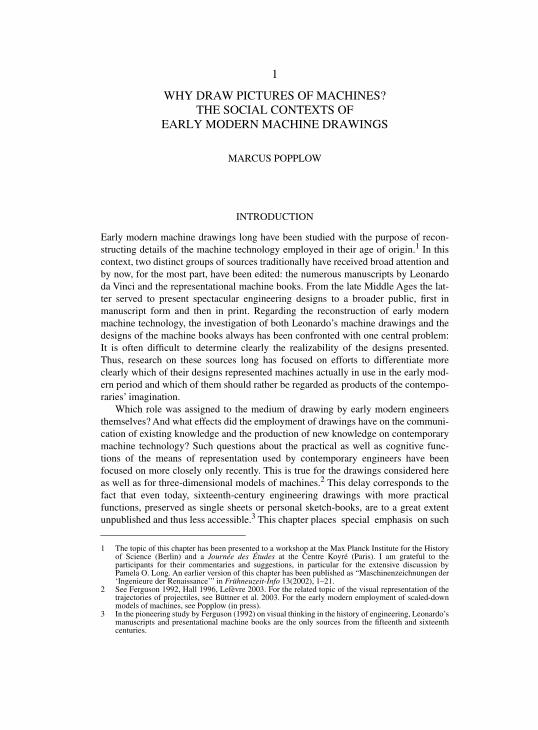
wolfgang lefèvre is Senior Scientist at the Max
Planck Institute for the History of Science in Berlin.
history of technology
“This excellent set of case studies offers many rewards. Erudite and skillful specialists, both
American and European, show in rich detail how drawings of machines were made and used in
early modern Europe. They illuminate the formal development of geometries of representation,
the social relations between engineers, artisans, and patrons, and a wide range of other topics.
Every essay rests on a deep foundation of drawings, lavishly reproduced and precisely analyzed.
Historians of art, of architecture, and of Renaissance court and urban culture, as well as
specialists on the history of science and technology, will find this volume indispensable.”
–anthony grafton, Henry Putnam University Professor of History, Princeton University
“Lefevre has orchestrated a rich collection of work by a stellar cast of Renaissance scholars, and
the result is a superb volume in the tradition of Michael Baxandall’s Painting and Experience in
Fifteenth- Century Italy. These studies explore the invention of pictorial language, as well as the
bodies of technical practice that permitted technical drawings to function as mediators between
practical engineering, design work, and theoretical knowledge for patrons and professional
engineers alike. A brilliant book!”
–tim lenoir, Chair, Program in History and Philosophy of Science, Stanford University
contributors
Filippo Camerota Rainer Leng David McGee
Mary Henninger-Voss Pamela O. Long Jeanne Peiffer
Wolfgang Lefevre Michael S. Mahoney Marcus Popplow
0-262-12269-3
,!7IA2G2-bccgjg!:t;K;k;K;k
Technical drawings by the architects and engineers of
the Renaissance made use of a range of new methods of
graphic representation. These drawings–among them
Leonardo da Vinci’s famous drawings of mechanical
devices–have long been studied for their aesthetic
qualities and technological ingenuity, but their signifi-
cance for the architects and engineers themselves is sel-
dom considered. The essays in Picturing Machines
1400–1700 take this alternate perspective and look at
how drawing shaped the practice of early modern engi-
neering. They do so through detailed investigations of
specific images, looking at more than one hundred that
range from sketches to perspective views to thoroughly
constructed projections.
In early modern engineering practice, drawings were
not merely visualizations of ideas but acted as models
that shaped ideas. Picturing Machines establishes basic
categories for the origins, purposes, functions, and con-
texts of early modern engineering illustrations, then
treats a series of topics that not only focus on the way
they became an indispensable means of engineering but
also reflect the main stages in their historical develop-
ment. The authors examine the social interaction con-
veyed by early machine images and their function as
communication between practitioners; the knowledge
either conveyed or presupposed by technical drawings,
as seen in those of Giorgio Martini and Leonardo;
drawings that required familiarity with geometry or
geometric optics, including the development of archi-
tectural plans; and technical illustrations that bridged
the gap between practical and theoretical mechanics.
picturing machines
1400–1700
picturing machines
1400–1700
edited by Wolfgang Lefevre`
pic
tu
ri
ng
ma
ch
in
es
14
00
–1
70
0
transformations: studies in the history
of science and technology
the mit press
Massachusetts Institute of Technology
Cambridge, Massachusetts 02142
http://mitpress.mit.edu
Lefevre, ed
itor
`
`
`
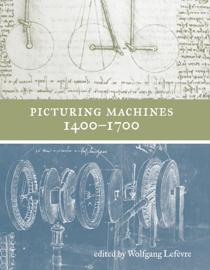
Cover images: top, Leonardo da Vinci, from Codex
Madrid I, courtesy Biblioteca Nacional, Madrid;
bottom, Leonardo da Vinci, from Codex Atlanticus,
Biblioteca Ambrosiana, Milan.
edited by Wolfgang Lefevre`
PICTURING MACHINES 1400–1700
TRANSFORMATIONS
STUDIES IN THE HISTORY OF SCIENCE AND TECHNOLOGY
JED BUCHWALD
GENERAL EDITOR
Mordechai Feingold, editor,
Jesuit Science and the Republic of Letters
Sungook Hong,
Wireless:
From Marconi‘s Black-Box to the Audion
Myles Jackson,
Spectrum of Belief: Joseph von Fraunhofer and the Craft ofPrecision Optics
Mi Gyung Kim,
Affinity,
That Elusive Dream: A Genealogy of the ChemicalRevolution
Janis Langins,
Conserving the Enlightenment: French Military Engineeringfrom Vauban to the Revolution
Wolfgang Lefèvre, editor,
Picturing Machines 1400–1700
William R. Newman and Anthony Grafton, editors,
Secrets of Nature:Astrology and Alchemy in Early Modern Europe
Alan J. Rocke,
Nationalizing Science: Adolphe Wurtz and the Battle forFrench Chemistry
PICTURING MACHINES 1400–1700
EDITED BY WOLFGANG LEFÈVRE
THE MIT PRESS
CAMBRIDGE, MASSACHUSETTS
LONDON, ENGLAND
© 2004 Massachusetts Institute of Technology
All rights reserved. No part of this book may be reproduced in any form by any electronic ormechanical means (including photocopying, recording, or information storage and retrieval)without permission in writing from the publisher.
This book was set in Times by Heinz Reddner, MPI for the History of Science, Berlin, and wasprinted and bound in the United States of America.
Library of Congress Cataloging-in-Publication Data
Picturing machines 1400–1700 / edited by Wolfgang Lefèvre. p. cm. — (Transformations)ISBN 0-262-12269-3 (alk. paper)1. Mechanical drawing. 2. Engineering graphics. I. Lefèvre, Wolfgang, 1941–II. Transformations (M.I.T. Press)
T353.P55 2004604.2—dc22 2003070620
10 9 8 7 6 5 4 3 2 1
CONTENTS
INTRODUCTION
Wolfgang Lefèvre
1
PART I: WHY PICTURES OF MACHINES?
Introduction to Part I 13
1 Why Draw Pictures of Machines? The Social Contexts of Early Modern Machine Drawings
Marcus Popplow
17
PART II: PICTORIAL LANGUAGES AND SOCIAL CHARACTERS
Introduction to Part II 51
2 The Origins of Early Modern Machine Design
David McGee
53
3 Social Character, Pictorial Style, and the Grammar of Technical Illustration in Craftsmen’s Manuscripts in the Late Middle Ages
Rainer Leng
85
PART III: SEEING AND KNOWING
Introduction to Part III 115
4 Picturing the Machine: Francesco di Giorgio and Leonardo da Vinci in the 1490s
Pamela O. Long
117
5 Measures of Success: Military Engineering and the Architectonic Understanding of Design
Mary Henninger-Voss
143
PART IV: PRODUCING SHAPES
Introduction to Part IV 173
6 Renaissance Descriptive Geometry: The Codification of Drawing Methods
Filippo Camerota
175
7 The Emergence of Combined Orthographic Projections
Wolfgang Lefèvre
209
8 Projections Embodied in Technical Drawings: Dürer and His Followers
Jeanne Peiffer
245

VI CONTENTS
PART V: PRACTICE MEETS THEORY
Introduction to Part V 279
9 Drawing Mechanics
Michael S. Mahoney
281
APPENDIX
Contributors 309
References 311
Name Index 335
Subject Index 339
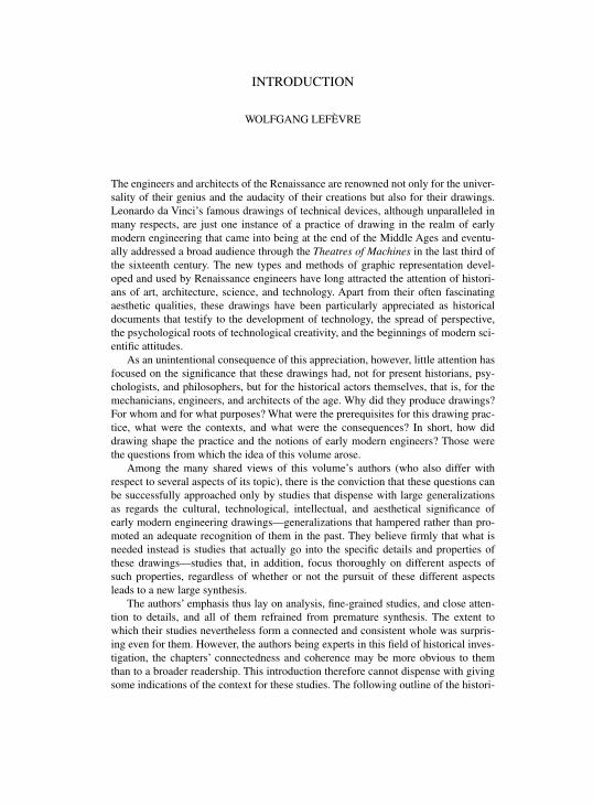
INTRODUCTION
WOLFGANG LEFÈVRE
The engineers and architects of the Renaissance are renowned not only for the univer-sality of their genius and the audacity of their creations but also for their drawings.Leonardo da Vinci’s famous drawings of technical devices, although unparalleled inmany respects, are just one instance of a practice of drawing in the realm of earlymodern engineering that came into being at the end of the Middle Ages and eventu-ally addressed a broad audience through the
Theatres of Machines in the last third ofthe sixteenth century. The new types and methods of graphic representation devel-oped and used by Renaissance engineers have long attracted the attention of histori-ans of art, architecture, science, and technology. Apart from their often fascinatingaesthetic qualities, these drawings have been particularly appreciated as historicaldocuments that testify to the development of technology, the spread of perspective,the psychological roots of technological creativity, and the beginnings of modern sci-entific attitudes.
As an unintentional consequence of this appreciation, however, little attention hasfocused on the significance that these drawings had, not for present historians, psy-chologists, and philosophers, but for the historical actors themselves, that is, for themechanicians, engineers, and architects of the age. Why did they produce drawings?For whom and for what purposes? What were the prerequisites for this drawing prac-tice, what were the contexts, and what were the consequences? In short, how diddrawing shape the practice and the notions of early modern engineers? Those werethe questions from which the idea of this volume arose.
Among the many shared views of this volume’s authors (who also differ withrespect to several aspects of its topic), there is the conviction that these questions canbe successfully approached only by studies that dispense with large generalizationsas regards the cultural, technological, intellectual, and aesthetical significance ofearly modern engineering drawings—generalizations that hampered rather than pro-moted an adequate recognition of them in the past. They believe firmly that what isneeded instead is studies that actually go into the specific details and properties ofthese drawings—studies that, in addition, focus thoroughly on different aspects ofsuch properties, regardless of whether or not the pursuit of these different aspectsleads to a new large synthesis.
The authors’ emphasis thus lay on analysis, fine-grained studies, and close atten-tion to details, and all of them refrained from premature synthesis. The extent towhich their studies nevertheless form a connected and consistent whole was surpris-ing even for them. However, the authors being experts in this field of historical inves-tigation, the chapters’ connectedness and coherence may be more obvious to themthan to a broader readership. This introduction therefore cannot dispense with givingsome indications of the context for these studies. The following outline of the histori-
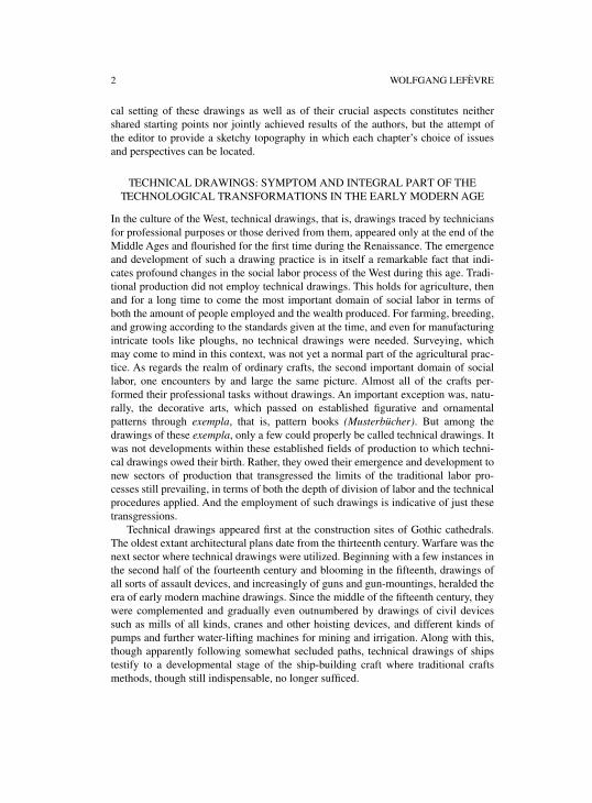
2 WOLFGANG LEFÈVRE
cal setting of these drawings as well as of their crucial aspects constitutes neithershared starting points nor jointly achieved results of the authors, but the attempt ofthe editor to provide a sketchy topography in which each chapter’s choice of issuesand perspectives can be located.
TECHNICAL DRAWINGS: SYMPTOM AND INTEGRAL PART OF THE TECHNOLOGICAL TRANSFORMATIONS IN THE EARLY MODERN AGE
In the culture of the West, technical drawings, that is, drawings traced by techniciansfor professional purposes or those derived from them, appeared only at the end of theMiddle Ages and flourished for the first time during the Renaissance. The emergenceand development of such a drawing practice is in itself a remarkable fact that indi-cates profound changes in the social labor process of the West during this age. Tradi-tional production did not employ technical drawings. This holds for agriculture, thenand for a long time to come the most important domain of social labor in terms ofboth the amount of people employed and the wealth produced. For farming, breeding,and growing according to the standards given at the time, and even for manufacturingintricate tools like ploughs, no technical drawings were needed. Surveying, whichmay come to mind in this context, was not yet a normal part of the agricultural prac-tice. As regards the realm of ordinary crafts, the second important domain of sociallabor, one encounters by and large the same picture. Almost all of the crafts per-formed their professional tasks without drawings. An important exception was, natu-rally, the decorative arts, which passed on established figurative and ornamentalpatterns through
exempla, that is, pattern books
(Musterbücher). But among thedrawings of these
exempla, only a few could properly be called technical drawings. Itwas not developments within these established fields of production to which techni-cal drawings owed their birth. Rather, they owed their emergence and development tonew sectors of production that transgressed the limits of the traditional labor pro-cesses still prevailing, in terms of both the depth of division of labor and the technicalprocedures applied. And the employment of such drawings is indicative of just thesetransgressions.
Technical drawings appeared first at the construction sites of Gothic cathedrals.The oldest extant architectural plans date from the thirteenth century. Warfare was thenext sector where technical drawings were utilized. Beginning with a few instances inthe second half of the fourteenth century and blooming in the fifteenth, drawings ofall sorts of assault devices, and increasingly of guns and gun-mountings, heralded theera of early modern machine drawings. Since the middle of the fifteenth century, theywere complemented and gradually even outnumbered by drawings of civil devicessuch as mills of all kinds, cranes and other hoisting devices, and different kinds ofpumps and further water-lifting machines for mining and irrigation. Along with this,though apparently following somewhat secluded paths, technical drawings of shipstestify to a developmental stage of the ship-building craft where traditional craftsmethods, though still indispensable, no longer sufficed.
INTRODUCTION 3
The emergence and spread of technical drawings thus was part and parcel of newdevelopments in certain exceptional fields in the realm of production that could becalled the high-tech sectors of the age. Moreover, these drawings were connectedwith those very features of all or some of these fields of advanced production bywhich they distinguished themselves from the traditional ways of production in agri-culture and ordinary crafts. The following five features deserve particular attention inthis respect, although not all of them occur in each of the sectors of advanced tech-nology.
First, technical drawings were connected with new forms of division of laborcharacteristic of some of the new high-tech production sectors—forms that developedfirst at the construction sites of Gothic cathedrals and later, outside architecture,above all along with shipbuilding and mining on a large scale. In these sectors, theflat hierarchy of the typical craft workshop was replaced by complex structures ofcooperation, responsibilities, and command. The chief engineer or architect, himselfsubordinated to clerical or secular commissioners or boards of commissioners, had toinstruct and coordinate masters and subcontractors from different crafts who, fortheir part, directed their teams. The task of coordination often comprised the harmo-nization of work carried out at different times and different places. Such intricateforms of cooperation among the different parties involved in a project of advancedtechnology necessitated not only new forms of communication but also new means ofcommunication. Technical drawings are perhaps the most striking of those newmeans.
Second, technical drawings were connected with new forms of knowledge propa-gation brought about by the new production sectors of advanced technology. In thesesectors, experience with and knowledge gained through new technologies could notbe exchanged and circulated effectively by means of the undeveloped and slow com-munication mechanisms of the medieval crafts. Rather, for these purposes, too, newmeans of communication were needed, technical drawings included.
Third, and in close relation to this, technical drawings were connected with newforms of learning and instruction that developed along with the new high-tech pro-duction. The traditional form in which craftsmen passed on knowledge and skills tothe next generation, that is, the system of apprenticeship and journeymen’s travelingthat rests essentially on learning by doing, proved to be insufficient to acquire all ofthe capabilities required by the advanced technologies. First forms of schooling tech-nical knowledge developed. In fact, the art of producing and reading technical draw-ings constituted a central part of the curriculum of the first technical schools, as isindicated in the very name of the first of these schools, namely the
Accademia deldisegno in Florence founded in 1563.
Fourth, technical drawings also were closely related to fundamental changes inthe body of practical knowledge induced by the advanced production sectors. Thisbody no longer comprised only the traditional experiences and skills of practitioners,but combined them with elements of knowledge that originated in sciences. Theexpanding employment of geometrical constructions and theorems in several practi-
4 WOLFGANG LEFÈVRE
cal contexts is particularly characteristic of this development. The broad range ofcompetence required by the new technologies is best represented by a social figurewho came into being with the new fields of advanced production, namely the engi-neer, who was in charge not only of designing and planning ambitious projects butalso of their actual realization through the coordinated cooperation of different kindsof crafts. For these engineers, experience in several crafts was no less important thancompetence in design and planning, which, for its part, included learned knowledgeas well as drawing capabilities.
Fifth, technical drawings were connected with the establishment of technology asa matter of public interest. Pictorial representations of machines and devices of allsorts were a chief means by which the protagonists of the new advanced productionsectors managed to attract the attention of the educated public for technologicalissues. With this, technology became, for the first time in the culture of the West,appreciated as a valuable sphere of culture. The technological transformations of theearly modern period entailed a cultural transformation in which drawings played asignificant role.
TECHNICAL DRAWINGS IN EARLY MODERN ENGINEERING
The practical role of technical drawings in early modern fields of advanced produc-tion was not fixed once and for all. Naturally, for which tasks technical drawingscould be employed depended partly on the needs of the engineering process in itsconcrete social embedment and partly on the capacity of drawings to meet suchneeds. However, both those needs and that capacity underwent changes—changesthat often were intertwined. By using drawings and, above all, by developing particu-lar pictorial languages, engineers discovered the possibilities given by the medium ofdrawings and broadened the spectrum of tasks for which drawings proved to be use-ful. Thus, an investigation of the actual functions of engineering drawings requiresattention to many different aspects.
Mediating Parties
The most obvious function of technical drawings was a social one, that is, their func-tion as a means of communication between different individuals or, more to the point,different kinds of individuals. They served as a means of communication betweenpractitioners, either those of equal rank or those in a hierarchical relation; betweencontracting parties, commissioners, and responsible practitioners, as well as the latterand subcontracting practitioners; and between practitioners and a broader publicinterested in new technology. Mere contemplation of the different constellations ofinteracting parties makes immediately obvious that “communication” is much toovague a term to characterize the variety of roles technical drawings played in suchinteractions. In one case, they may have conveyed proposals; in another, they mayhave documented an agreement; in yet others, they may have fixed decisions, given
INTRODUCTION 5
instructions, served as a basis for consultations and negotiations, exchanged experi-ences, imposed and secured control, advertised inventions, services, and projects,taught a community of readers, illustrated arguments, and so on. Each of these differ-ent cases of social interaction in which technical drawings are employed comprisesnot only a specific constellation of differing interests but also a specific constellationof differing experiences, competence, and knowledge. Thus, technical drawingscould only function successfully as a means of communication and mediation if theyallowed for the different and differently informed views of the parties involved.Drawings that served understanding between practitioners of equal rank jointlyengaged in a certain project highlighted, or for that matter omitted, other aspects anddetails of a technical object than drawings that tried to convey an idea of the object toa commissioner. Each case required a different emphasis on completeness, precision,and neatness, and different distinctness as regards information about, for instance, thefunction of the device in question or its construction.
Studying technical drawings thus can reveal an entire world of social relationsbetween different groups of individuals in which technological projects were embed-ded. And, conversely failing to take the concrete mediating role of a certain technicaldrawing into account may seriously impair the understanding of it. Giving testimonyas much to the social form of early modern high-tech production as to the technologyemployed, the technical drawings of the age must be read with social-historicalexpertise as well as with technological competence. However, the ways in which theextant drawings were passed on often destroyed their original relations to other mate-rials and thus important hints on which a reconstruction of this social context couldhave rested. As some of this volume’s chapters show, it often is impossible to deter-mine the original purpose and the circumstances of a technical drawing. In somecases, however, an analysis of the drawing style may prove helpful.
Between Pictures and Plans
The variety of ways in which technical drawings were employed as means of com-munication in the social world around the most advanced technologies of the ageinvoluntarily draws attention to the astonishingly flexible capability of drawings as amedium. How did this medium succeed in serving so many different communicationtasks, each of which had different conditions, demands, and purposes? A partialanswer to this question may be found in the fact that, on closer inspection, themedium of drawings proves to comprise a whole of graphic languages—that of pic-tures, of diagrams, of plans, and so on. From a semiotic perspective, each of these dif-ferent graphic languages follows particular rules and grammars. Accordingly, each ofthem demands particular expertise for rendering objects in the framework of its rulesand also for reading and understanding such renderings. Architectural plans of somecomplexity, for instance, are only partly understandable to nonexperts. Obviously,different graphical languages presuppose different knowledge and are thereforeinvolved in the discriminations that govern the social distribution of knowledge in a
6 WOLFGANG LEFÈVRE
culture. Furthermore, each of these graphic languages has its specific advantages anddisadvantages. The graphic language that rules the construction of orthographicplans, for instance, may be unequaled as regards precise information about angles,distances, proportions, and so on. But it cannot compete with the language of per-spective rendering when the purpose is to convey an impression of the object as asolid body situated in a surrounding space. Thus there is not only a social aspect ofthe employment of a specific graphic language but also a material one, that is, theaspect of the possibilities and limits of rendering characteristic of each of these lan-guages. These differences between the material capacities of the various graphic lan-guages by their very nature suggest which specific language is suitable in a certaincase. However, the practitioner must additionally consider which of these languagesis best understood by the audience in question. Compromises between these two con-cerns may be unavoidable, and such compromises are, indeed, a characteristic featureof the technical drawings of this age.
Architects and engineers of the early modern period did not only make use ofmultiple different graphical languages—and often in a virtuose manner—in a certainsense, they also must be regarded as the inventors of these languages. True, from theliterary estate of Classic Antiquity, they inherited some clues to the graphic languagesemployed by their ancient predecessors; and equally true, they could build on somedrawing conventions and geometrical techniques used by medieval architects andtechnicians. They did not have to start from scratch. Yet, as regards the different pro-jection techniques developed in Antiquity—orthographic projection, perspective,geographic projection—each of them was reinvented rather than rediscovered in theRenaissance, and subsequently further developed and refined in an absolutely autono-mous manner. Furthermore, against the background of the spread of perspective ren-dering in the fine arts, the schematic style characteristic of representing machines inthe Middle Ages was replaced by a specific style of rendering machines on a singlesheet, which was furthermore supplemented by the elaboration of an arsenal of artifi-cial views such as cutaways, exploded views, and so on.
Surveying the styles and techniques of picturing developed from the modestbeginnings in the late Middle Ages up to the famous drawings of Leonardo and to thesplendid
Theatres of Machines at the end of the sixteenth century, one encounters anadmirably rich world of pictorial languages that was engendered along with theadvanced technologies of the age. The range of these languages—from sketches, toperspective views from a deliberately chosen fictitious viewpoint, and to thoroughlyconstructed projections—testifies to the wealth of graphic abilities the community ofengineers and architects commanded. At the same time it mirrors the broad spectrumof competences that had become characteristic of this community—ranging frompractical skill and artisanal experience to learned knowledge.
INTRODUCTION 7
Shaping Engineering
Among the many striking features of early modern engineering drawings, there is onethat deserves particular attention. In contrast to architecture, scaled orthographicplans—ground plans, elevations, sections—were the exception rather than the rule inthe realm of machine engineering. In this realm, pictorial representations in a quasi-perspective style prevailed. This finding suggests that, in this age, drawings were notas indispensable a means for designing and manufacturing machines as plans andblueprints are today. In the inceptive stage of the designing process, sketches mayhave been employed by Renaissance engineers in by and large the same manner as bycontemporary engineers—I will come back to this in a moment. But, as far as theextant engineer drawings of the age show, the subsequent manufacturing process wasnot guided by exact plans as it is today. Even the few known instances of employmentof orthographic plans in the manufacturing process suggest that these plans served asa means of orientation rather than as a blueprint. The Renaissance engineers couldapparently confine themselves to telling the craftsmen in charge of execution somedecisive details and leaving the concrete shaping of the machine parts to them. How-ever, this reliance on craftsmen was not reliance on personal experience and tacitknowledge alone. Rather, they were relying on craftsmen who were well equippedwith a rich arsenal of geometrical aids developed over centuries—several drawinginstruments, templates of all sorts, practitioners’ techniques of creating nontrivialgeometrical shapes and developing one geometric figure from another. If one takesthis arsenal of practical geometrical aids into account, the machine drawings ofRenaissance engineers may appear less inappropriate for the manufacturing processthan at first glance. Taken together with the geometrical means at the constructionsite, early modern machine drawings become recognizable as means of the real con-struction process.
The employment of drawings in design processes deserves further attention. Inthese processes, drawings are not simply visualizations of ideas. Rather they functionas material means that shape ideas. Their role is that of models that simultaneouslyprovide a fictitious and a real opportunity to test possible arrangements of machineparts, try out new combinations and alternative shapes of these parts, and so on. Asmaterial creations in space, drawings are subjected to the laws of space and thus rep-resent real conditions as regards possible spatial relations of rendered objects. (Thefamous drawings by M. C. Escher, which seemingly transgress these laws, confirmthis impressively.) The advantages of such flat models on paper over solid ones madeof wood or clay are obvious. They can be created and changed almost instantly. Pre-supposing some drawing skill on the part of the engineer, their restraint to two dimen-sions can be compensated for almost completely. They are incomparably flexible andallow unfettered experimentation. They furthermore allow unparalleled concentrationon issues of interest thanks to the possibility of omitting all interfering or distractingparts of the device in question and reducing it to its essentials. However, the limits ofthese models on paper are obvious as well. Being two-dimensional creations, theirrepresentational potency ends when the focus is no longer on shapes of machine
8 WOLFGANG LEFÈVRE
parts, their spatial relations, and the kinematic significance of such relations—whenphysical dimensions come to the fore, encompassing the mass and force of thedesigned object. Nevertheless, within their limits, drawings became an indispensablemeans of the design process and in this way shaped the very element of the engineer-ing practice on which its fame as an outstandingly innovative activity essentiallyrests.
THE VOLUME’S FOCUS AND ARRANGEMENT
As stated above, this volume focuses on the functions and significance technicaldrawings actually had for the professional practice of early modern engineers andarchitects. It will not address other interesting aspects such as the aesthetic quality ofthese drawings, the manifold levels of meanings that these drawings had beyond thecontext of engineering, their place in the visual culture of the Renaissance, and so on.But, as may be obvious after this short introductory outline, despite this concentrationon the engineering context, the subject matter is so rich in aspects, dimensions, andstructures that one single book cannot aspire to cover it all. Furthermore, as alsostated at the beginning, the authors of this volume do not try to present a syntheticview of early modern engineering drawings in the practical context of engineering.Instead they confine themselves to detailed investigations of such drawings under avariety of viewpoints that pertain to this context. If they nevertheless claim to offermore than just a collection of articles that deal with some aspects of this theme, thisconfidence rests on the conviction that they have concentrated their efforts on suchaspects of the topic that are essential for an adequate understanding of technicaldrawings as means of early modern engineering. The five parts into which the book isdivided represent these aspects.
Without anticipating the short introductions that precede each of these parts, theirrespective focus can be indicated as follows. Part I, entitled
Why Pictures ofMachines? and containing chapter 1 by Marcus Popplow, is about basic categoriesfor ordering the huge and extraordinarily diverse store of extant technical drawings ofthe age with respect to their origin, purposes, functions, and contexts, thereby provid-ing a first survey of this material. Part II, with the title
Pictorial
Languages andSocial Characters, which contains chapters 2 and 3 by David McGee and RainerLeng, respectively, is occupied with the development of the specific style of earlymodern machine rendering and the question of whether and how this style can beconsidered a response to the different social functions of these drawings. Part III,
Seeing and Knowing, with chapter 4 by Pamela O. Long and chapter 5 by Mary Hen-ninger-Voss, addresses knowledge linked with technical drawings, be it the knowl-edge presupposed and/or conveyed by them, or knowledge that is presupposed butcannot be conveyed. Part IV,
Producing Shapes, with chapters 6 through 8 by FilippoCamerota, Wolfgang Lefèvre, and Jeanne Peiffer, respectively, focuses on the devel-opment of drawing techniques that required, either from the beginning or in thecourse of their evolution, familiarity with learned knowledge such as geometry or
INTRODUCTION 9
geometric optics. Part V, finally,
Practice Meets Theory, with chapter 9 by Michael S.Mahoney, is dedicated to technical drawings at the interface between practical andtheoretical mechanics.
To a certain extent, particularly as regards the fifteenth century, the arrangementof the volume also reflects main stages in the historical development of early modernengineering drawings. After chapter 1, which provides an analytical survey of thetechnical drawings of this age, chapters 2 and 3 discuss the emergence and the firststage of the specific early modern type of machine rendering in fifteenth-century Italy(Taccola) and Germany
(Büchsenmeistertraktate), respectively. Whereas chapter 7contains an outline of the development of architectural plans up to the first decades ofthe sixteenth century, chapter 4 presents the mature stage that machine drawingsachieved with Giorgio Martini and Leonardo da Vinci in the second half of the fif-teenth century, a maturity that was not surpassed by the succeeding development ofearly modern engineering drawing. This further development is not traced coherentlyin this volume, with the conspicuous consequence that the famous
Theatres ofMachines from the last decades of the sixteenth and the beginning of the seventeenthcenturies are not discussed as a special issue. This omission resulted mainly from thevolume’s focus on the functions and significance technical drawings had in the engi-neering practice. Although partly deriving from those of immediate practical context,and although constituting in no way a separate or particular genus of engineeringdrawings, the drawings of the
Theatres served the propagation rather than the realpractice of engineering. The same holds for the rightly renowned woodcuts inGeorgius Agricola’s
De re metallica from 1556. The fact that this treatise and those
Theatres, the majority of which is accessible through exemplary modern editions,have enjoyed thorough scholarly attention in the last decades made the decision eas-ier to refrain from addressing them in favor of much less investigated issues such asdecision making by means of plans (chapter 5), drawing techniques of a learned char-acter (chapters 6 through 8), and the relation between engineering drawings and theo-retical mechanics (chapter 9).
ACKNOWLEDGMENTS
The idea of this volume arose after a small conference on engineering drawings of theRenaissance, which was organized by the editor together with David McGee andMarcus Popplow and held at the Max Planck Institute for the History of Science,Berlin, in summer 2001. The authors who eventually joined in this book projectcirculated drafts of their chapters several times and met in winter 2002, again at theMPI in Berlin, for a thorough discussion of each contribution as well as of the focusand arrangement of the volume as a whole. My first thanks go to them. Seriouslyengaged in the volume’s topic and cooperating in an unusual spirit of goodfellowship, they never failed in promptly and patiently reacting to all of the greaterand smaller demands such a book entails. Our joint work was an exciting andrewarding experience!
10 WOLFGANG LEFÈVRE
Warm thanks also go to James Bennett, Raz Chen, Judith V. Field, Bert S. Hall,Volker Hoffmann, Alex G. Keller, Antoinette Roesler–Friedenthal, and Thomas B.Settle, who contributed to the 2001 conference and discussed earlier versions of anumber of the volume’s chapters both critically and constructively.
The planning, organization, and realization of such an extensive and costly pro-duction process was only possible with the backing of the Max Planck Institute forthe History of Science, Berlin. Jürgen Renn, who runs Department I of the institute,where preclassical mechanics constitutes the subject of one of the current long-termprojects, provided the requisite support for the enterprise and accompanied it throughits course with unceasing sympathy and encouragement. Many thanks!
Furthermore I would like to thank Jed Z. Buchwald for the decision to include thebook in his Transformations series. Dealing with a topic that relates to the history ofboth science and technology, the volume could not have found better company.
Like machines, to actually come into being, books need to be not only designed(written) but also manufactured. My thanks go therefore to Angelika Irmscher, HeinzReddner, and Susan Richter, who assisted in the editorial work and helped to bringthe manuscript with all the figures to its final camera-ready form. Finally, I want tothank Sara Meirowitz, responsible for the science, technology, and society books atthe MIT Press, who discreetly and reliably provided every support needed.
PART IWHY PICTURES OF MACHINES?

INTRODUCTION TO PART I
In the pictorial world of the Middle Ages and the Renaissance, depictions of technicalobjects occur everywhere, in paintings and frescoes, on stained-glass windows, inreliefs carved in wood, chiselled in stone, cast in bronze, in illuminated Bibles,prayer-books, books of hours, on single-sheet woodcuts and engravings, in manu-scripts and printed treatises with illustrations, on sketches, in notebooks, on plans—everywhere. Only a small fraction of them are technical drawings and thus subjectsfor this book. Presupposing a rather pragmatic definition, the authors of this volumeconsider those drawings to be technical that were either traced (or commissioned tobe traced) and used by technicians in the pursuit of their professional life or derivedfrom such practitioners’ drawings. Of these technical drawings, only machine draw-ings and a few architectural drawings are dealt with in this volume. However, despitethis concentration, the number of drawings addressed here is still huge. According tosome experts’ estimation, for the period 1400–1700 alone, one has to reckon with fiveto ten thousand drawings of machines and machine parts.
The unsatisfactory vagueness of such guesses results from the fact that nobodyknows how many such drawings might be buried in such locations as the archives ofstates, cities, dioceses, monasteries, and princely families, and in the manuscriptdepartments of libraries and museums. The expectation that hitherto unknown mate-rials will surface there in the future rests primarily on a suspicious feature of theknown material. The bulk of this material consists in presentational drawings thatwere published in booklets and books—manuscript books
(Bilderhandschriften) aswell as printed ones—in the early modern period. Only a small part consists of work-shop drawings pertaining either to the documents of commissioners of machinery andbuildings or to the private store of engineers and architects themselves. This fact cancertainly be explained by the assumption that drawings of the design and constructionprocess of technical artifacts were not kept but thrown away after a certain span oftime. However, the unbalanced ratio of the presentational and the workshop shares ofthe known machine drawings of this period may also result, at least to some extent,from the storage and display policy of archives and libraries in past eras, when thecultural divide between the realm of technology and the realm of fine arts and litera-ture was still prevalent.
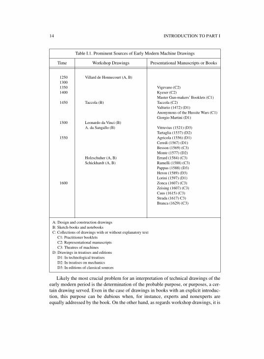
For a first orientation, table I.1 showing the most important sources of early mod-ern engineering drawings, to which the chapters of this volume frequently refer, maybe convenient.
The prevalence of the presentational over the workshop material among the extantengineering drawings poses a serious problem to our enterprise. For a picture of theactual role technical drawings played in the practice of engineers and architects,workshop drawings are naturally of far more significance than the presentationalones. The latter may be telling in this respect as well. But only on the basis of thor-ough investigations of the drawings actually used in the design and construction pro-cesses will one be able to determine to what extent and through which of theirfeatures certain presentational drawings, too, give testimony to the use of drawings inearly modern engineering.
14 INTRODUCTION TO PART I
Likely the most crucial problem for an interpretation of technical drawings of theearly modern period is the determination of the probable purpose, or purposes, a cer-tain drawing served. Even in the case of drawings in books with an explicit introduc-tion, this purpose can be dubious when, for instance, experts and nonexperts areequally addressed by the book. On the other hand, as regards workshop drawings, it is
Table I.1. Prominent Sources of Early Modern Machine Drawings
Time Workshop Drawings Presentational Manuscripts or Books
1250130013501400
1450
1500
1550
1600
Villard de Honnecourt (A, B)
Taccola (B)
Leonardo da Vinci (B)A. da Sangallo (B)
Holzschuher (A, B)Schickhardt (A, B)
Vigevano (C2)Kyeser (C2)Master Gun-makers’ Booklets (C1)Taccola (C2)Valturio (1472) (D1)Anonymous of the Hussite Wars (C1)Giorgio Martini (D1)
Vitruvius (1521) (D3)Tartaglia (1537) (D2)Agricola (1556) (D1)Ceredi (1567) (D1)Besson (1569) (C3)Monte (1577) (D2)Errard (1584) (C3)Ramelli (1588) (C3)Pappus (1588) (D3)Heron (1589) (D3)Lorini (1597) (D1)Zonca (1607) (C3)Zeising (1607) (C3)Caus (1615) (C3)Strada (1617) C3)Branca (1629) (C3)
A: Design and construction drawingsB: Sketch-books and notebooksC: Collections of drawings with or without explanatory text
C1: Practitioner booklets C2: Representational manuscripts C3: Theatres of machines
D: Drawings in treatises and editionsD1: In technological treatises D2: In treatises on mechanics D3: In editions of classical sources
INTRODUCTION TO PART I 15
sometimes impossible to determine the purpose. “Why pictures of machines?”—thisseemingly simple question proves to be an intricate one. Familiarity with a consider-able amount of the extant material is presupposed to outline some characteristic fea-tures of these engineering drawings and to propose convincing and useful categoriesaccording to which this material may be ordered. Presenting such an outline and pro-posing those categories, chapter 1 by Marcus Popplow not only provides an analyticsurvey of the subject of this volume but also prepares the ground for the subsequentchapters.

1
WHY DRAW PICTURES OF MACHINES? THE SOCIAL CONTEXTS OF
EARLY MODERN MACHINE DRAWINGS
MARCUS POPPLOW
INTRODUCTION
Early modern machine drawings long have been studied with the purpose of recon-structing details of the machine technology employed in their age of origin.1 In thiscontext, two distinct groups of sources traditionally have received broad attention andby now, for the most part, have been edited: the numerous manuscripts by Leonardoda Vinci and the representational machine books. From the late Middle Ages the lat-ter served to present spectacular engineering designs to a broader public, first inmanuscript form and then in print. Regarding the reconstruction of early modernmachine technology, the investigation of both Leonardo’s machine drawings and thedesigns of the machine books always has been confronted with one central problem:It is often difficult to determine clearly the realizability of the designs presented.Thus, research on these sources long has focused on efforts to differentiate moreclearly which of their designs represented machines actually in use in the early mod-ern period and which of them should rather be regarded as products of the contempo-raries’ imagination.
Which role was assigned to the medium of drawing by early modern engineersthemselves? And what effects did the employment of drawings have on the communi-cation of existing knowledge and the production of new knowledge on contemporarymachine technology? Such questions about the practical as well as cognitive func-tions of the means of representation used by contemporary engineers have beenfocused on more closely only recently. This is true for the drawings considered hereas well as for three-dimensional models of machines.2 This delay corresponds to thefact that even today, sixteenth-century engineering drawings with more practicalfunctions, preserved as single sheets or personal sketch-books, are to a great extentunpublished and thus less accessible.3 This chapter places special emphasis on such
1 The topic of this chapter has been presented to a workshop at the Max Planck Institute for the Historyof Science (Berlin) and a
Journée des Études at the Centre Koyré (Paris). I am grateful to theparticipants for their commentaries and suggestions, in particular for the extensive discussion byPamela O. Long. An earlier version of this chapter has been published as “Maschinenzeichnungen der‘Ingenieure der Renaissance’” in
Frühneuzeit-Info 13(2002), 1–21.2 See Ferguson 1992, Hall 1996, Lefèvre 2003. For the related topic of the visual representation of the
trajectories of projectiles, see Büttner et al. 2003. For the early modern employment of scaled-downmodels of machines, see Popplow (in press).
3 In the pioneering study by Ferguson (1992) on visual thinking in the history of engineering, Leonardo’smanuscripts and presentational machine books are the only sources from the fifteenth and sixteenthcenturies.
18 MARCUS POPPLOW
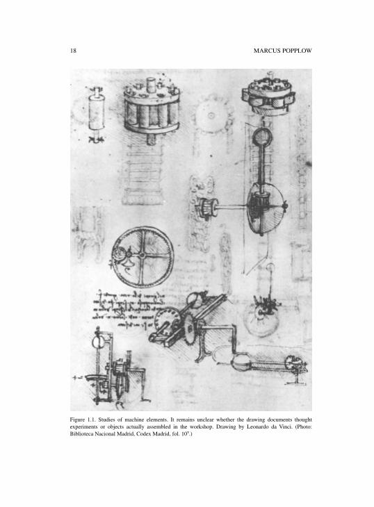
Figure 1.1. Studies of machine elements. It remains unclear whether the drawing documents thoughtexperiments or objects actually assembled in the workshop. Drawing by Leonardo da Vinci. (Photo:Biblioteca Nacional Madrid, Codex Madrid, fol. 10v.)
WHY DRAW PICTURES OF MACHINES? 19
less formal drawings not addressed to a broader public. It is such sources that docu-ment how the medium of “drawing” was indispensable for planning, realizing, andmaintaining large-scale technological projects in the early modern period.
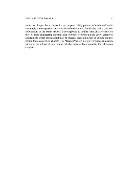
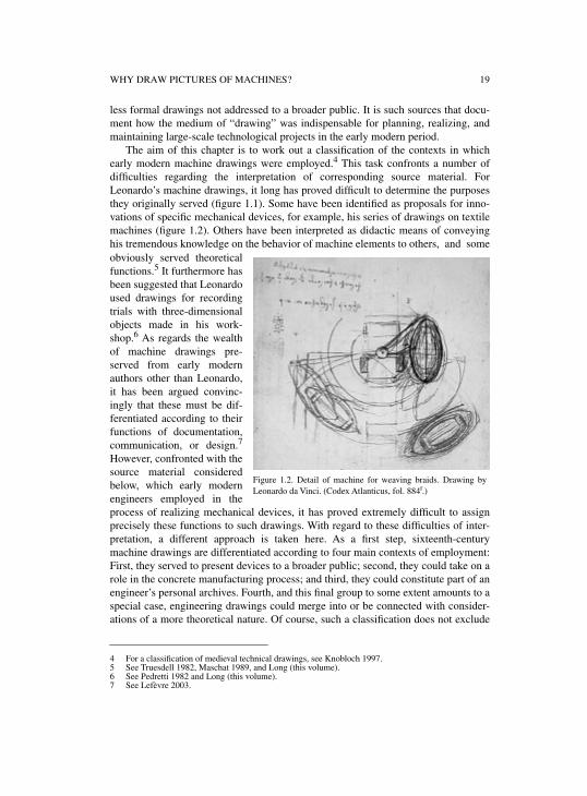
The aim of this chapter is to work out a classification of the contexts in whichearly modern machine drawings were employed.4 This task confronts a number ofdifficulties regarding the interpretation of corresponding source material. ForLeonardo’s machine drawings, it long has proved difficult to determine the purposesthey originally served (figure 1.1). Some have been identified as proposals for inno-vations of specific mechanical devices, for example, his series of drawings on textilemachines (figure 1.2). Others have been interpreted as didactic means of conveyinghis tremendous knowledge on the behavior of machine elements to others, and someobviously served theoreticalfunctions.5 It furthermore hasbeen suggested that Leonardoused drawings for recordingtrials with three-dimensionalobjects made in his work-shop.6 As regards the wealthof machine drawings pre-served from early modernauthors other than Leonardo,it has been argued convinc-ingly that these must be dif-ferentiated according to theirfunctions of documentation,communication, or design.7
However, confronted with thesource material consideredbelow, which early modernengineers employed in theprocess of realizing mechanical devices, it has proved extremely difficult to assignprecisely these functions to such drawings. With regard to these difficulties of inter-pretation, a different approach is taken here. As a first step, sixteenth-centurymachine drawings are differentiated according to four main contexts of employment:First, they served to present devices to a broader public; second, they could take on arole in the concrete manufacturing process; and third, they could constitute part of anengineer’s personal archives. Fourth, and this final group to some extent amounts to aspecial case, engineering drawings could merge into or be connected with consider-ations of a more theoretical nature. Of course, such a classification does not exclude
4 For a classification of medieval technical drawings, see Knobloch 1997.5 See Truesdell 1982, Maschat 1989, and Long (this volume).6 See Pedretti 1982 and Long (this volume).7 See Lefèvre 2003.
Figure 1.2. Detail of machine for weaving braids. Drawing byLeonardo da Vinci. (Codex Atlanticus, fol. 884r.)
20 MARCUS POPPLOW
the possibility that one and the same drawing could be employed in more than one ofthese four contexts over the course of time.
The following remarks are limited to describing the situation in the sixteenth cen-tury without investigating the question of the origins of the employment of machinedrawings for more practical purposes in the Middle Ages. With the exception of thenumerous illustrated gunners’ manuals,8 early engineering drawings from the four-teenth and fifteenth centuries have been preserved almost exclusively in the contextof the production of presentational manuscripts. However, it is hard to imagine thatthe numerous fifteenth-century manuscript machine books could have been producedwithout any foundation in some less formalized practice. Scattered textual evidencethat still awaits closer investigation indeed testifies to a more informal employment ofmachine drawings as early as the beginning of the fifteenth century.9 Furthermore, itmust be noted that any attempt to explain when and why drawings came to beemployed in mechanical engineering in the Middle Ages must take into considerationthe tradition of late medieval architectural drawings.10 As the different roles ofmachine builder, architect, and fortification engineer emerged more clearly only inthe course of the sixteenth century, it can be assumed that the employment of such acrucial medium as drawing in earlier periods still showed similar characteristics in allthree of these fields.11 As the focus of this chapter lies on the social contexts ofemploying machine drawings in the sixteenth century, neither will the developmentand use of different graphic techniques—most prominently, changes induced by theinvention of perspective in the fifteenth century—be investigated here.12
1. PRESENTING DEVICES TO A BROADER PUBLIC
The above-mentioned machine books in manuscript13 and in print14 served to presentmachines to a broader public, formally continuing a manuscript tradition dating backto Antiquity and the Arab Middle Ages.15 This public initially consisted of courtlyaudiences before expanding ever more to learned laymen and fellow technical expertsduring the sixteenth century. Drawings and later woodcuts and engravings allowed
8 See Leng (this volume).9 Documents from the
fabbrica of Milan cathedral mention in passing that proposals for a mechanicallydriven stone-saw were to be submitted first in the form of a drawing before the most promising designswere required to be presented as scaled-down models. See Dohrn–van Rossum 1990, 204–208.
10 See Lefèvre (this volume).11 Contexts of employing architectural and fortification drawings in the early modern period have received
only scarce attention to date. See Schofield 1991 and Frommel 1994a. Architectural treatises from thefifteenth century onwards often contain explicit discussions of the role of the medium of drawing in thedesign process. See Thoenes 1993.
12 See Ferguson 1992, Lamberini (in press), and Camerota (this volume). For the density of informationconveyed and the broad variety of graphic techniques employed in Leonardo’s machine drawings, seeHall 1976b; Heydenreich et al. 1980; and Galluzzi 1982. The argument brought forth by SamuelEdgerton, according to which geometrically constructed perspective drawings in sixteenth-centurymachine books paved the way for the “geometrization of nature” in the “Scientific Revolution” has, bynow, been refuted convincingly. See Mahoney 1985 and Hall 1996, 21–28.
13 See Hall 1982a, Hall 1982b, Galluzzi 1993, Galluzzi 1996a, Friedrich 1996, Leng 2002, Long 2001,102–142, and Leng (this volume).
14 See Keller 1978, Knoespel 1992, and Dolza and Vérin 2001.15 See Lefèvre 2002 and Hill 1996.
WHY DRAW PICTURES OF MACHINES? 21
these audiences to study siege engines, mills, water-lifting devices, and other exam-ples of early modern machine technology. In the fourteenth and fifteenth centuries,these manuscripts contained mostly military devices. Well-known examples are themanuscripts assembled by Guido da Vigevano (c. 1335), Konrad Kyeser (1405),Mariano Taccola (1449), Roberto Valturio (1455, printed in 1472), and the authorknown as “Anonymous of the Hussite Wars” (c. 1470/1480). The first pioneeringmanuscripts showing engines for civil purposes were composed in Italy, again, byMariano Taccola (c. 1430/1440) and Francesco di Giorgio Martini (c. 1470/1480).While large devices for military and civil purposes had existed only rather vaguely inthe visual memory of medieval contemporaries, this situation now changed, at leastfor those among whom these manuscripts circulated. With the regard to the works ofKonrad Kyeser, Mariano Taccola, and Francesco di Giorgio Martini, some dozens oreven hundreds of copies of the original manuscripts have been discovered. They
stillawait closer investigation concerning the questions of who commissioned them andwho was responsible for the artistic process of producing the manuscript copies.16
Towards the end of the sixteenth century, with the printed machine books of JacquesBesson (1578), Jean Errard (1584), Agostino Ramelli (1588), Vittorio Zonca (1607),Heinrich Zeising (1612ff), Salomon de Caus (1615), Jacopo Strada (1618), and Gio-vanni Branca (1629), machines for civil purposes became a subject of learned knowl-edge as well. In addition to the printed
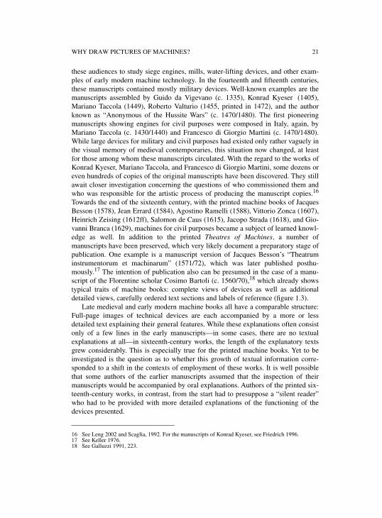
Theatres of Machines, a number ofmanuscripts have been preserved, which very likely document a preparatory stage ofpublication. One example is a manuscript version of Jacques Besson’s “Theatruminstrumentorum et machinarum” (1571/72), which was later published posthu-mously.17 The intention of publication also can be presumed in the case of a manu-script of the Florentine scholar Cosimo Bartoli (c. 1560/70),18 which already showstypical traits of machine books: complete views of devices as well as additionaldetailed views, carefully ordered text sections and labels of reference (figure 1.3).
Late medieval and early modern machine books all have a comparable structure:Full-page images of technical devices are each accompanied by a more or lessdetailed text explaining their general features. While these explanations often consistonly of a few lines in the early manuscripts—in some cases, there are no textualexplanations at all—in sixteenth-century works, the length of the explanatory textsgrew considerably. This is especially true for the printed machine books. Yet to beinvestigated is the question as to whether this growth of textual information corre-sponded to a shift in the contexts of employment of these works. It is well possiblethat some authors of the earlier manuscripts assumed that the inspection of theirmanuscripts would be accompanied by oral explanations. Authors of the printed six-teenth-century works, in contrast, from the start had to presuppose a “silent reader”who had to be provided with more detailed explanations of the functioning of thedevices presented.
16 See Leng 2002 and Scaglia, 1992. For the manuscripts of Konrad Kyeser, see Friedrich 1996. 17 See Keller 1976.18 See Galluzzi 1991, 223.
22 MARCUS POPPLOW
Figure 1.3. High-quality drawing of a dredger with didactic implications. Note the details of themechanism drawn separately below. Drawing by Cosimo Bartoli, c. 1565. (Florence, Biblioteca NazionaleCentrale, Palatino E.B. 16.5 (II), fol. 60r, courtesy Ministero per i Beni e le Attività Culturali, all rightsreserved.)
Regarding techniques of graphic representation, the perspective illustrations inprinted books on machines did not differ much from fifteenth-century presentationalmanuscripts: An elevated viewpoint enabled the spectator to discern machine ele-ments that would remain hidden if the device were represented from the front on
WHY DRAW PICTURES OF MACHINES? 23
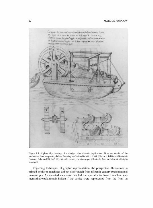
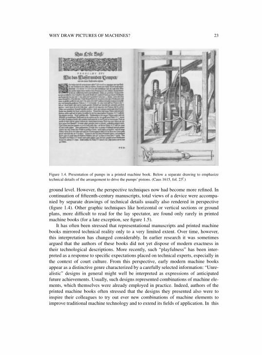
Figure 1.4. Presentation of pumps in a printed machine book. Below a separate drawing to emphasizetechnical details of the arrangement to drive the pumps’ pistons. (Caus 1615, fol. 23r.)
ground level. However, the perspective techniques now had become more refined. Incontinuation of fifteenth-century manuscripts, total views of a device were accompa-nied by separate drawings of technical details usually also rendered in perspective(figure 1.4). Other graphic techniques like horizontal or vertical sections or groundplans, more difficult to read for the lay spectator, are found only rarely in printedmachine books (for a late exception, see figure 1.5).
It has often been stressed that representational manuscripts and printed machinebooks mirrored technical reality only to a very limited extent. Over time, however,this interpretation has changed considerably. In earlier research it was sometimesargued that the authors of these books did not yet dispose of modern exactness intheir technological descriptions. More recently, such “playfulness” has been inter-preted as a response to specific expectations placed on technical experts, especially inthe context of court culture. From this perspective, early modern machine booksappear as a distinctive genre characterized by a carefully selected information: “Unre-alistic” designs in general might well be interpreted as expressions of anticipatedfuture achievements. Usually, such designs represented combinations of machine ele-ments, which themselves were already employed in practice. Indeed, authors of theprinted machine books often stressed that the designs they presented also were toinspire their colleagues to try out ever new combinations of machine elements toimprove traditional machine technology and to extend its fields of application. In this
24 MARCUS POPPLOW
sense, the machine books could beahead of their time without necessar-ily losing their relation to technicalpractice. A number of European terri-torial powers explicitly promoted theapplication of mechanical technologyby granting privileges for the inven-tion of newly designed mechanicaldevices.19 This practice, which spreadall throughout Europe in the sixteenthcentury, provides a very concretebackground for the sense of experi-mentation conveyed by the broad vari-ety of designs in the machine books.Machine books served the communi-cation between engineers and poten-tial investors or interested members ofthe republic of letters, rather than thatbetween engineers and artisans orworkmen. The functions performedeven by the late medieval manuscriptswere manifold: They could serve toentertain or to present factual informa-tion, or to prove the erudition ofprincely commissioners and promotethe self-advertisement of technicalexperts. Such implications of the prac-
tice of authorship in early modern engineering have only recently began to be investi-gated more closely.20 Assembling textual and visual information on machinetechnology with the aim of presentation to others created a new kind of reflectingknowledge. This new kind of knowledge distinguished the engineer from the ordinaryartisan and thus underlined the legitimacy of claims to higher social status of thesetechnical experts.
Even though machine books served as a kind of visual inventory of contemporarytechnical ideas even among the engineers themselves, they played only a marginalrole for engineers’ everyday practice. The materiality of technology was oftenignored in these presentational treatises. Machines in these books should be under-stood as a product of the engineer’s brain, his
ingenium; their material realization wasnot the topic of these books. The organizational activities of the engineer on thebuilding site were mentioned as scarcely as materials, measurements or gear ratios—it was considered self-evident that such factors had to be established at a later point
19 See Popplow 1998b.20 See Long 2001.
Figure 1.5. Vertical section of machine elements of thewater-lifting device shown in figure 4. (Caus 1615, fol.24r.)
WHY DRAW PICTURES OF MACHINES? 25
Figu
re 1
.6.
Surv
ey p
lan
by t
he t
own’
s m
aste
r b u
ilder
Wol
f Ja
cob
Stro
mer
of
the
Nur
embe
rg m
ills
alon
gsid
e th
e ri
ver
Pegn
itz (
deta
il),
1601
. (P
hoto
:G
erm
anis
ches
Nat
iona
lmus
eum
Nür
nber
g, H
B 3
089,
Kap
s 10
55h.
)
26 MARCUS POPPLOW
of time at the site. However, illustrations of machines were often incorporated inlively landscapes or workshop scenarios to suggest the possibility of immediateemployment.
Information on the process of creating illustrations for presentational treatises isscarce. For most of the earlier manuscripts, the persons known as “authors,” such asGuido da Vigevano, Konrad Kyeser, or Roberto Valturio, were responsible only forthe texts and the composition of the treatises and commissioned the production of theillustrations to artists who remained anonymous. The selection of these artists andhow they were instructed about which devices they had to illustrate, and how andwith which technical details, remains unclear. This is also true for the woodcuts andengravings in the later printed works. That artists visited each machine at its originalsite is documented, as an exception, in the case of Georgius Agricola’s preparationsfor his encyclopaedia on mining,
De re metallica, published in 1556. His letters showthat he had to send different artists to the mining centres of Saxony several times untilhe found one who produced drawings of the machines employed there in a qualitysufficient to serve as templates for the woodcuts.21 It is difficult to imagine that thiswas a standard practice, however; artists sometimes might have drawn from three-dimensional models of machines or from some sort of sketch. In any case, the pro-duction process of such books on machines presupposes some tradition of moreinformal machine drawing, of which only faint traces have been preserved from theperiod preceding Leonardo da Vinci’s notebooks.22
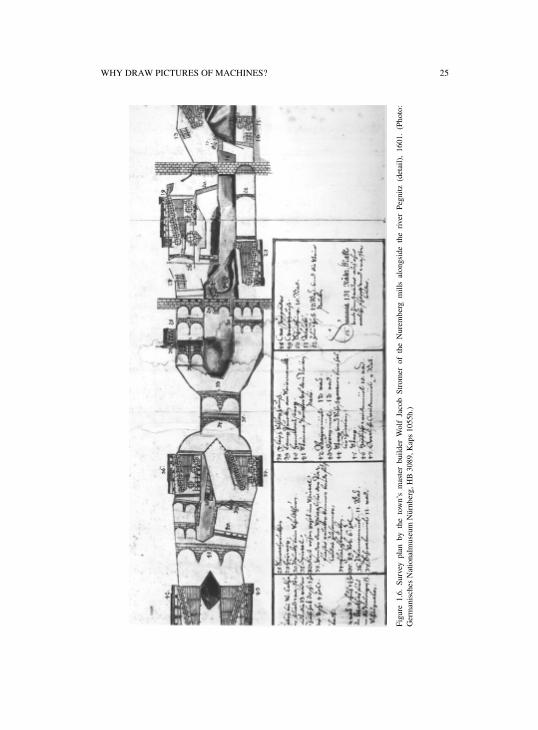
In addition to their incorporation in machine books, machine drawings with repre-sentative functions have also been preserved as single leaves. A special case is pro-vided by plans kept in communal archives representing, for example, a town’swaterways. From early fifteenth-century Basle, such a plan has been preserved with acoloured scheme of the different waterworks crossing the town. It is assembled ofpieces of parchment and is, in total, nearly ten meters long.23 In other cases, suchplans also depicted water-mills alongside the town’s waterways in symbolized form,that is, as mill-wheels turned ninety degrees laterally (figure 1.6).
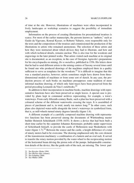
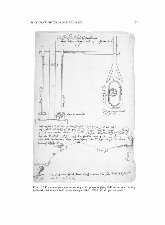
A different example of a carefully composed machine drawing with representa-tive functions has been preserved among the documents of Württemberg masterbuilder Heinrich Schickhardt (1558–1635). It shows a device that had been built ashort time earlier by the carpenter Johannes Kretzmaier, probably under supervisionof Schickhardt himself, to provide the castle of Hellenstein near Heidenheim withwater (figure 1.7).24 Between the source and the castle, a height difference of a totalof ninety meters had to be overcome. The drawing emphasized only the core elementof the transmission machinery: a combination of a lantern and an oval rack. It servedto transfer the rotary motion provided by the water-wheel to the reciprocating motionof the horizontal beam driving the piston rods of the pumps. Indispensable construc-tion details of the device, like the guide rails of the rack, are missing. The lower part
21 See Kessler–Slotta 1994.22 See McGee (this volume).23 See Schnitter 2000.24 See Müller 2000.
WHY DRAW PICTURES OF MACHINES? 27
Figure 1.7. Commented presentational drawing of the pumps supplying Hellenstein castle. Drawingby Heinrich Schickhardt, 1606 or after. (Stuttgart, HStA, N220 T149, all rights reserved.)
28 MARCUS POPPLOW
of the drawing serves to visualize the concrete setting of employment: at the bottomleft, the building that housed the device; above right, Hellenstein castle. In addition tospecifications of measurements and the performance of the device, a written com-mentary signed by Schickhardt testifies to the documentary character of the sheet:“This is an artificial and useful device of which only few or even none are to be foundneither in Italy, nor in France or Germany in these times.”25 The exact purpose forwhich this drawing had been produced nevertheless remains unclear.
2. MACHINE DRAWINGS IN THE PROCESS OF REALIZING MECHANICAL DEVICES
Starting in the late Middle Ages, the separation of the social roles of engineer andartisan became more clearly discernible. While the former was responsible for thedesign and the organization of a given project, the latter carried out the actual work.This development is discussed as one of the central prerequisites for the growing rel-evance of drawings to mechanical engineering since the late Middle Ages.26 In thesixteenth century, in any case, drawings in the process of realizing mechanicaldevices served the engineer to communicate with the investor on the one hand and(although presumably to a lesser extent) with the artisans carrying out the work onthe other.
Communication with the investor especially concerned the preparatory stage ofrealizing mechanical devices. With regard to the competition among early modernengineering experts, drawings could serve to present engineers’ abilities at a foreigncourt, even though for such purposes the demonstration of scaled-down models pre-sumably was preferred, because of the more immediate impression it created. Both ofthese media played a central role in the above-mentioned practice of granting privi-leges for inventions.27 Applicants for such a privilege in a certain territory often sub-mitted drawings or models to underline the credibility of their inventions. Suchpresentations, however, were not necessarily required, as in any case the inventor hadto prove the realizability of his invention after the privilege had been granted by con-structing a test specimen in full size in the course of the subsequent six to twelvemonths. In some cases, applicants presented a whole set of inventions by means ofillustrated manuscripts, which ultimately strongly resembled manuscript machinebooks. This was true in the case of the above-mentioned manuscript by Jacques Bes-son, the designs of which were protected by a privilege in 1569 when the compilationwas presented to King Charles IX.28 A quite similar manuscript was composed in1606 by the Spanish engineer Jerónimo de Ayanz for King Philipp III.29 To obtain aprivilege for inventions, Ayanz presented drawings of forty-eight of his inventions,
25 “Ist ein künstlich nutzlich werckh, der gleichen wenig oder gar keins dieser Zeit weder in Italien,Franckhreich oder Teütschland gefunden wirt.” Stuttgart, HStA, N220 T149.
26 See McGee (this volume).27 See Popplow 1998b.28 See Keller 1976, 76.29 See Tapia 1991, 53–256.
WHY DRAW PICTURES OF MACHINES? 29
most of which were presented as sketches in perspective and accompanied by exten-sive descriptive texts.
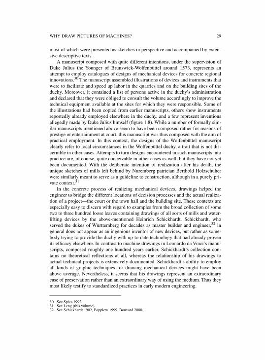
A manuscript composed with quite different intentions, under the supervision ofDuke Julius the Younger of Brunswick-Wolfenbüttel around 1573, represents anattempt to employ catalogues of designs of mechanical devices for concrete regionalinnovations.30 The manuscript assembled illustrations of devices and instruments thatwere to facilitate and speed up labor in the quarries and on the building sites of theduchy. Moreover, it contained a list of persons active in the duchy’s administrationand declared that they were obliged to consult the volume accordingly to improve thetechnical equipment available at the sites for which they were responsible. Some ofthe illustrations had been copied from earlier manuscripts, others show instrumentsreportedly already employed elsewhere in the duchy, and a few represent inventionsallegedly made by Duke Julius himself (figure 1.8). While a number of formally sim-ilar manuscripts mentioned above seem to have been composed rather for reasons ofprestige or entertainment at court, this manuscript was thus composed with the aim ofpractical employment. In this context, the designs of the Wolfenbüttel manuscriptclearly refer to local circumstances in the Wolfenbüttel duchy, a trait that is not dis-cernible in other cases. Attempts to turn designs encountered in such manuscripts intopractice are, of course, quite conceivable in other cases as well, but they have not yetbeen documented. With the deliberate intention of realization after his death, theunique sketches of mills left behind by Nuremberg patrician Berthold Holzschuherwere similarly meant to serve as a guideline to construction, although in a purely pri-vate context.31
In the concrete process of realizing mechanical devices, drawings helped theengineer to bridge the different locations of decision processes and the actual realiza-tion of a project—the court or the town hall and the building site. These contexts areespecially easy to discern with regard to examples from the broad collection of sometwo to three hundred loose leaves containing drawings of all sorts of mills and water-lifting devices by the above-mentioned Heinrich Schickhardt. Schickhardt, whoserved the dukes of Württemberg for decades as master builder and engineer,32 ingeneral does not appear as an ingenious inventor of new devices, but rather as some-body trying to provide the duchy with up-to-date technology that had already provenits efficacy elsewhere. In contrast to machine drawings in Leonardo da Vinci’s manu-scripts, composed roughly one hundred years earlier, Schickhardt’s collection con-tains no theoretical reflections at all, whereas the relationship of his drawings toactual technical projects is extensively documented. Schickhardt’s ability to employall kinds of graphic techniques for drawing mechanical devices might have beenabove average. Nevertheless, it seems that his drawings represent an extraordinarycase of preservation rather than an extraordinary way of using the medium. Thus theymost likely testify to standardized practices in early modern engineering.
30 See Spies 1992.31 See Leng (this volume).32 See Schickhardt 1902, Popplow 1999, Bouvard 2000.
30 MARCUS POPPLOW
Figure 1.8. Presentational drawing of a device for stamping and mixing lime allegedly inventedby Duke Julius of Brunswick-Wolfenbüttel, c. 1573. (Photo: Niedersächsisches StaatsarchivWolfenbüttel, Instrumentenbuch I, fol. 31r.)
WHY DRAW PICTURES OF MACHINES? 31
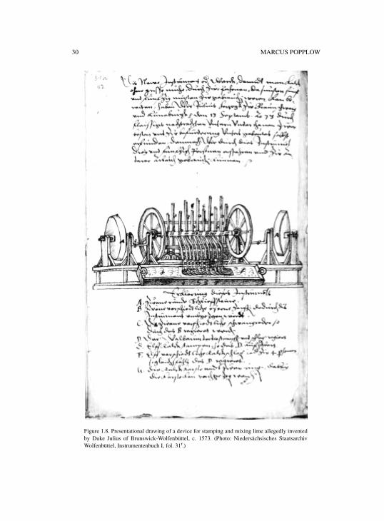
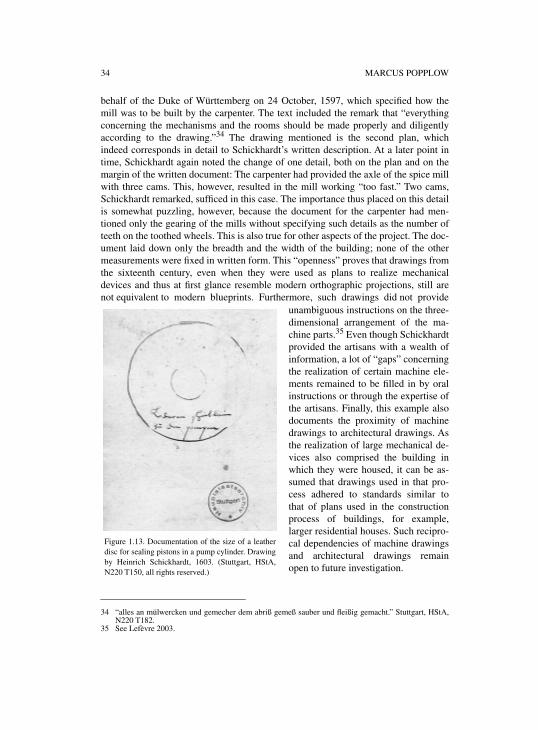
Around 1600, Heinrich Schickhardt supervised the building of several mills inMontbéliard, a project extensively documented in his papers.33 One of the devicesrealized was a paper-mill. A survey drawing of this mill shows, in an idealized way,the most important parts of its inventory—two of the basins where soaked rags werereduced to pulp as the raw material for the production of paper have been carefullyomitted to leave space to show such components as the mill’s press (figure 1.9). At
Figure 1.9. Inventory of a paper-mill in Montbéliard. Drawing by Heinrich Schickhardt, c. 1597. (Stuttgart,HStA, N220 T193, all rights reserved.)
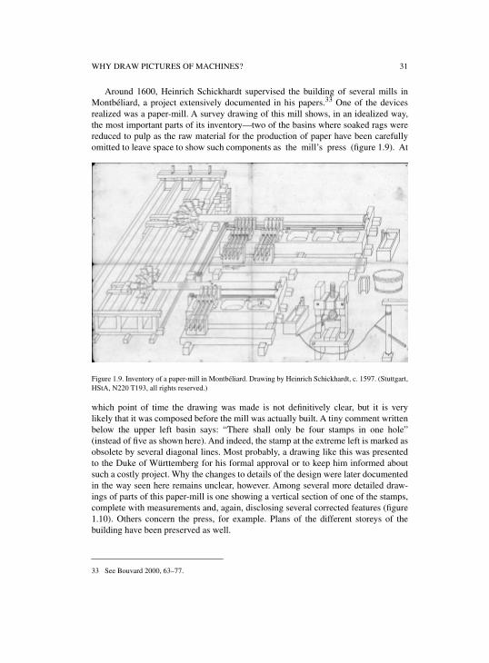
which point of time the drawing was made is not definitively clear, but it is verylikely that it was composed before the mill was actually built. A tiny comment writtenbelow the upper left basin says: “There shall only be four stamps in one hole”(instead of five as shown here). And indeed, the stamp at the extreme left is marked asobsolete by several diagonal lines. Most probably, a drawing like this was presentedto the Duke of Württemberg for his formal approval or to keep him informed aboutsuch a costly project. Why the changes to details of the design were later documentedin the way seen here remains unclear, however. Among several more detailed draw-ings of parts of this paper-mill is one showing a vertical section of one of the stamps,complete with measurements and, again, disclosing several corrected features (figure1.10). Others concern the press, for example. Plans of the different storeys of thebuilding have been preserved as well.
33 See Bouvard 2000, 63–77.
32 MARCUS POPPLOW
Figure 1.10. Vertical section of the cam-shaft and one of the stamps of a paper-mill in Montbéliard.Drawing by Heinrich Schickhardt, c. 1597. (Stuttgart, HStA, N220 T186, all rights reserved.)
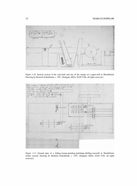
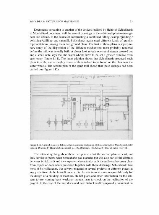
Figure 1.11. Ground plan of a fulling-/stamp-/grinding-/polishing-/drilling-/sawmill in Montbéliard,earlier version. Drawing by Heinrich Schickhardt, c. 1597. (Stuttgart, HStA, N220 T182, all rightsreserved.)
WHY DRAW PICTURES OF MACHINES? 33
Documents pertaining to another of the devices realized by Heinrich Schickhardtin Montbéliard document well the role of drawings in the relationship between engi-neer and artisan. In the course of constructing a combined fulling-/stamp-/grinding-/polishing-/drilling- and sawmill, Schickhardt again used different kinds of graphicrepresentations, among them two ground plans. The first of these plans is a prelimi-nary study of the disposition of the different mechanisms most probably renderedbefore the mill was actually built: A closer look reveals one set of stamps crossed outand a small note says that the water-wheels have to be set a greater distance fromeach other (figure 1.11). The latter addition shows that Schickhardt produced suchplans to scale, and a roughly drawn scale is indeed to be found on the plan near thewater-wheels. The second plan of the same mill shows that these changes had beencarried out (figure 1.12).
Figure 1.12. Ground plan of a fulling-/stamp-/grinding-/polishing-/drilling-/sawmill in Montbéliard, laterversion. Drawing by Heinrich Schickhardt, c. 1597. (Stuttgart, HStA, N220 T182, all rights reserved.)
The interesting thing about these two plans is that the second plan, at least, notonly served to record what Schickhardt had planned, but was also part of the contractbetween Schickhardt and the carpenter who actually built the mill—as becomes clearfrom copies of documents preserved together with these drawings. Schickhardt, likemost of his colleagues, was always engaged in several projects in different places atany given time. As he himself once wrote, he was in most cases responsible only forthe design of a building or machine. He left plans and other information for the arti-sans to use, coming back weeks or months later to check on the realization of theproject. In the case of the mill discussed here, Schickhardt composed a document on
34 MARCUS POPPLOW
behalf of the Duke of Württemberg on 24 October, 1597, which specified how themill was to be built by the carpenter. The text included the remark that “everythingconcerning the mechanisms and the rooms should be made properly and diligentlyaccording to the drawing.”34 The drawing mentioned is the second plan, whichindeed corresponds in detail to Schickhardt’s written description. At a later point intime, Schickhardt again noted the change of one detail, both on the plan and on themargin of the written document: The carpenter had provided the axle of the spice millwith three cams. This, however, resulted in the mill working “too fast.” Two cams,Schickhardt remarked, sufficed in this case. The importance thus placed on this detailis somewhat puzzling, however, because the document for the carpenter had men-tioned only the gearing of the mills without specifying such details as the number ofteeth on the toothed wheels. This is also true for other aspects of the project. The doc-ument laid down only the breadth and the width of the building; none of the othermeasurements were fixed in written form. This “openness” proves that drawings fromthe sixteenth century, even when they were used as plans to realize mechanicaldevices and thus at first glance resemble modern orthographic projections, still arenot equivalent to modern blueprints. Furthermore, such drawings did not provide
unambiguous instructions on the three-dimensional arrangement of the ma-chine parts.35 Even though Schickhardtprovided the artisans with a wealth ofinformation, a lot of “gaps” concerningthe realization of certain machine ele-ments remained to be filled in by oralinstructions or through the expertise ofthe artisans. Finally, this example alsodocuments the proximity of machinedrawings to architectural drawings. Asthe realization of large mechanical de-vices also comprised the building inwhich they were housed, it can be as-sumed that drawings used in that pro-cess adhered to standards similar tothat of plans used in the constructionprocess of buildings, for example,larger residential houses. Such recipro-cal dependencies of machine drawingsand architectural drawings remainopen to future investigation.
34 “alles an mülwercken und gemecher dem abriß gemeß sauber und fleißig gemacht.” Stuttgart, HStA,N220 T182.
35 See Lefèvre 2003.
Figure 1.13. Documentation of the size of a leatherdisc for sealing pistons in a pump cylinder. Drawingby Heinrich Schickhardt, 1603. (Stuttgart, HStA,N220 T150, all rights reserved.)
WHY DRAW PICTURES OF MACHINES? 35
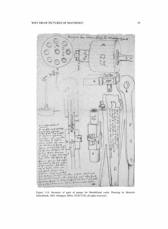
Figure 1.14. Inventory of parts of pumps for Montbéliard castle. Drawing by HeinrichSchickhardt, 1603. (Stuttgart, HStA, N220 T150, all rights reserved.)
36 MARCUS POPPLOW
A rarely documented and completely different type of drawing could play a minorrole in the process of realizing mechanical devices: drawings determining the size ofworkpieces. Such dimensioning was, of course, a procedure that had long beenrequired in any kind of building project and was solved by different means such asmoulds and templates. Given its increasing availability in the sixteenth century, papercould be used for such a purpose as well. Such procedures seem especially likely inthe production of the numerous toothed wheels for clockwork and automata. Anexample of this kind of drawing, again from Schickhardt’s legacy, concerns a leatherring that served to seal up pistons moving up and down in pumping cylinders. Thisdrawing with the remark “leather disc for the pumps”36 (figure 1.13) probably wasproduced because the wear and tear of these discs frequently made their replacementnecessary such that it was advisable to always have new discs at hand. Another draw-ing makes clearer the context of the employment of this disc: Here Schickhardt wasconcerned with restoring the pumps for the water supply of Montbéliard castle. Theleather disc is to be found on the upper right part of the page, represented by the thincircle fixed to the right of the wooden piston marked “M” (figure 1.14). The functionof this visual inventory of the parts of the pump is, again, not discernible.
3. MACHINE DRAWINGS AS ENGINEERS’ PRIVATE ARCHIVES
Early modern engineers in many cases assembled personal archives with drawings oftheir own projects and drawings of devices realized by others. To be sure, the sorts ofdrawings discussed so far also could find their place in such collections. The follow-ing paragraphs, however, after briefly discussing drawings that served to illustrateengineers’ own thought experiments and to document their own experiences withmachines or machine elements in their workshop, will concentrate on different sets ofdrawings that helped engineers record the design of mechanical devices they saw dur-ing their travels.
As has been remarked above, it is still open to what extent Leonardo da Vinci’sdrawings of machine elements represented not only thought experiments, butarrangements of objects that had been tested in his workshop (figure 1.15).37 In otherengineers’ documents known to date, hardly any drawings with these two functionscan be discerned. This makes it extremely difficult to judge the role they might haveplayed in the design practice of the fifteenth and sixteenth centuries in relation tothree-dimensional arrangements or scaled-down models of machines. An early exam-ple of drawings that might be interpreted as thought experiments are a number ofsmall studies of war ships in a manuscript by Mariano Taccola.38
Drawings produced by engineers while traveling are documented to a muchgreater extent than the thought experiments mentioned in the preceding paragraph.Parallel to artists’ and architects’ practices of keeping model books for reproducing
36 “lederne scheiblein zu den pompen.” Stuttgart, HStA, N220 T150.37 See Long (this volume).38 See McGee (this volume).
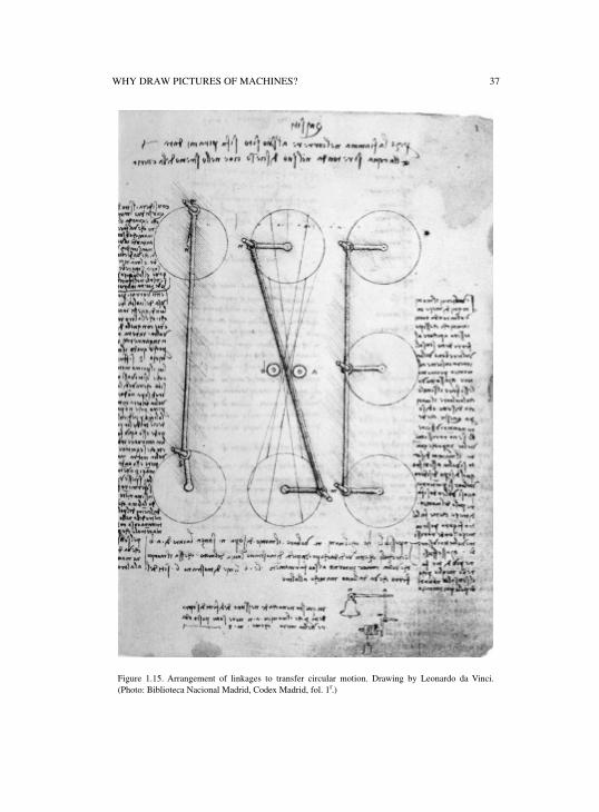
WHY DRAW PICTURES OF MACHINES? 37
Figure 1.15. Arrangement of linkages to transfer circular motion. Drawing by Leonardo da Vinci.(Photo: Biblioteca Nacional Madrid, Codex Madrid, fol. 1r.)
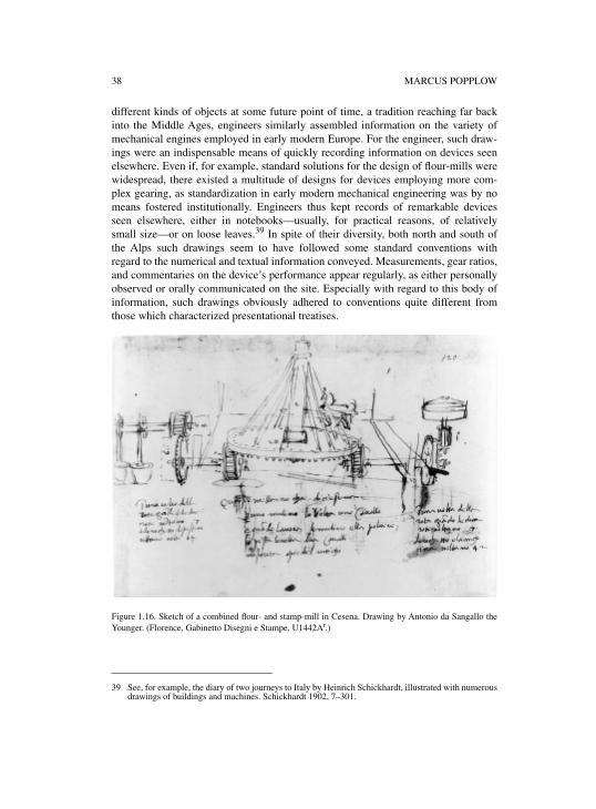
38 MARCUS POPPLOW
different kinds of objects at some future point of time, a tradition reaching far backinto the Middle Ages, engineers similarly assembled information on the variety ofmechanical engines employed in early modern Europe. For the engineer, such draw-ings were an indispensable means of quickly recording information on devices seenelsewhere. Even if, for example, standard solutions for the design of flour-mills werewidespread, there existed a multitude of designs for devices employing more com-plex gearing, as standardization in early modern mechanical engineering was by nomeans fostered institutionally. Engineers thus kept records of remarkable devicesseen elsewhere, either in notebooks—usually, for practical reasons, of relativelysmall size—or on loose leaves.39 In spite of their diversity, both north and south ofthe Alps such drawings seem to have followed some standard conventions withregard to the numerical and textual information conveyed. Measurements, gear ratios,and commentaries on the device’s performance appear regularly, as either personallyobserved or orally communicated on the site. Especially with regard to this body ofinformation, such drawings obviously adhered to conventions quite different fromthose which characterized presentational treatises.
Figure 1.16. Sketch of a combined flour- and stamp-mill in Cesena. Drawing by Antonio da Sangallo theYounger. (Florence, Gabinetto Disegni e Stampe, U1442Ar.)
39 See, for example, the diary of two journeys to Italy by Heinrich Schickhardt, illustrated with numerousdrawings of buildings and machines. Schickhardt 1902, 7–301.
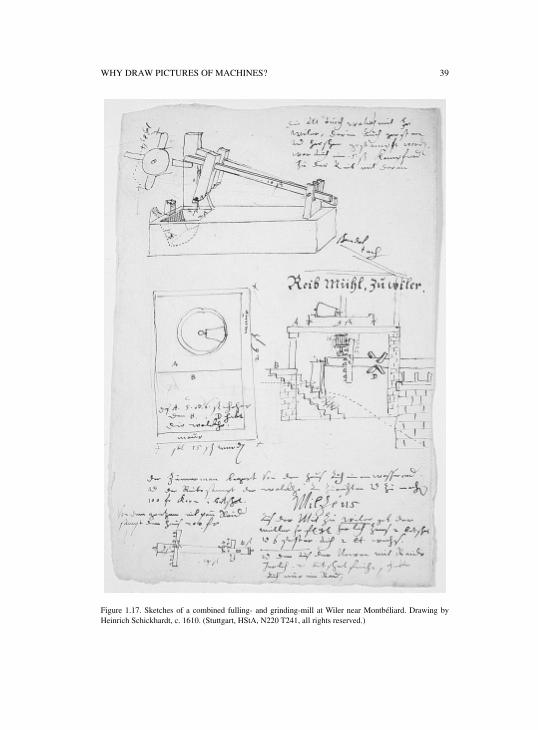
WHY DRAW PICTURES OF MACHINES? 39
Figure 1.17. Sketches of a combined fulling- and grinding-mill at Wiler near Montbéliard. Drawing byHeinrich Schickhardt, c. 1610. (Stuttgart, HStA, N220 T241, all rights reserved.)
40 MARCUS POPPLOW
An early example of such drawings recording devices seen elsewhere is providedby Antonio da Sangallo the Younger in the first half of the sixteenth century. It showsa horse-driven combination of a flour- and a stamp-mill, which is said to have beenlocated in Cesena (figure 1.16).40 As was typical, the leaf includes information onmeasurements and gear ratios as they had been observed on the site. Similar exam-ples from that period can also be found in the famous sketch-book of the Volpaia fam-ily from the 1520s.41 Another example, one of numerous of such leaves includedamong the personal records of Heinrich Schickhardt, represents a combined fulling-and grinding-mill near Montbéliard.42 This drawing exhibits an even greater densityof information than the Sangallo example (figure 1.17). It furthermore testifies to thefact that, compared to the presentational treatises, engineers in such cases sometimesused a broader variety of graphic techniques to record what they had seen. Schick-hardt, in this case as in many others, used not only perspective representations, butalso vertical sections and top views. In each part of the drawing, he noted dimensionsof the different parts of the machine and also wrote down the gear ratios of themachinery. The production of such drawings required a considerable sense ofabstraction. Firstly, machines were housed in buildings, which, of course, were nottransparent, so that it was actually impossible to see the machinery as it was por-trayed by the drawing. Secondly, the point of view chosen for the representation ofthe machine—at a certain distance and slightly above ground level—is practicallyalways constructed virtually, as it was hardly available to contemporary spectators.
How exactly engineers later made use of information recorded in this way is diffi-cult to say. Of course, such drawings not only served individual purposes, but alsoprovided a basis for communication with artisans, colleagues, and potential investors.In the case of Heinrich Schickhardt, the importance of such a collection is proven bythe fact that he kept such leaves at home in a desk with drawers, each of which wasreserved for one special kind of device.43 In the sixteenth century, such archives ofwell-off engineers also usually included a collection of books—not necessarily ontechnical subjects only. Lists of books owned by engineers are documented, forexample, for Leonardo da Vinci; again, Heinrich Schickhardt; and for the Italianengineer Giambattista Aleotti.44 Towards the end of the sixteenth century, such per-sonal libraries might also comprise printed machine books. At the same time, illustra-tions from printed books were also copied for private use. This is testified to by aloose leaf from the papers of Heinrich Schickhardt showing copies of machinesemployed in the German mining regions as they had been depicted in Georgius Agri-cola’s De re metallica of 1556 (figure 1.18). The reason for the production of exactlythese copies are unclear, as Schickhardt himself owned a copy of Agricola’s book.
40 See Frommel 1994c, 418.41 For this manuscript in general, see Brusa 1994, 657–658.42 See Bouvard 2000, 60–63.43 This can be deduced from a note in a document pertaining to the building of a mill in Pleidelsheim:
“Mühlwehr wie das gemacht; ist beü den wasser gebeüen in der oberen Schubladen zuo finden.”Stuttgart, HStA, N220 T212.
44 For Leonardo, see Leonardo 1974, II fol. 2v–3r and Leonardo 1987, 239–257; for Schickhardt, seeSchickhardt 1902, 331–342; for Aleotti, see Fiocca 1995.
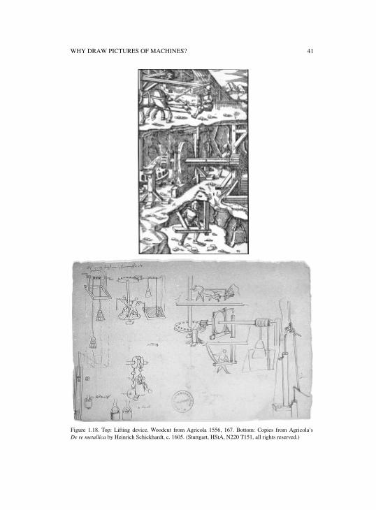
WHY DRAW PICTURES OF MACHINES? 41
Figure 1.18. Top: Lifting device. Woodcut from Agricola 1556, 167. Bottom: Copies from Agricola’sDe re metallica by Heinrich Schickhardt, c. 1605. (Stuttgart, HStA, N220 T151, all rights reserved.)
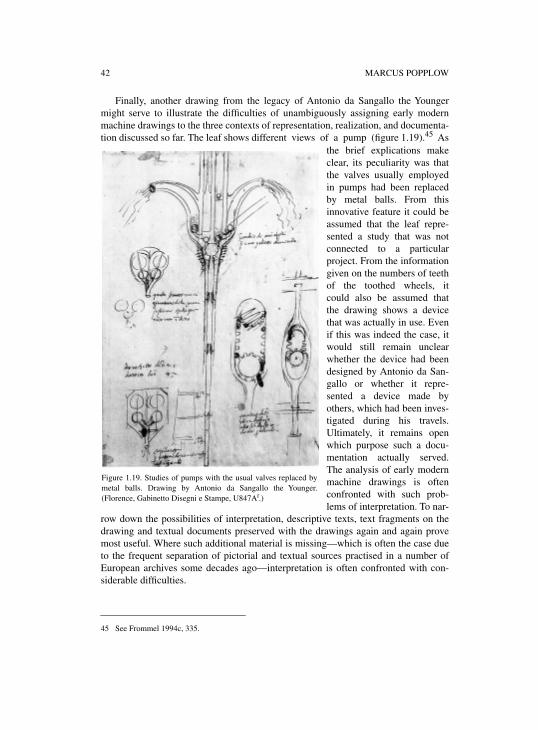
42 MARCUS POPPLOW
Finally, another drawing from the legacy of Antonio da Sangallo the Youngermight serve to illustrate the difficulties of unambiguously assigning early modernmachine drawings to the three contexts of representation, realization, and documenta-tion discussed so far. The leaf shows different views of a pump (figure 1.19).45 As
the brief explications makeclear, its peculiarity was thatthe valves usually employedin pumps had been replacedby metal balls. From thisinnovative feature it could beassumed that the leaf repre-sented a study that was notconnected to a particularproject. From the informationgiven on the numbers of teethof the toothed wheels, itcould also be assumed thatthe drawing shows a devicethat was actually in use. Evenif this was indeed the case, itwould still remain unclearwhether the device had beendesigned by Antonio da San-gallo or whether it repre-sented a device made byothers, which had been inves-tigated during his travels.Ultimately, it remains openwhich purpose such a docu-mentation actually served.The analysis of early modernmachine drawings is oftenconfronted with such prob-lems of interpretation. To nar-
row down the possibilities of interpretation, descriptive texts, text fragments on thedrawing and textual documents preserved with the drawings again and again provemost useful. Where such additional material is missing—which is often the case dueto the frequent separation of pictorial and textual sources practised in a number ofEuropean archives some decades ago—interpretation is often confronted with con-siderable difficulties.
45 See Frommel 1994c, 335.
Figure 1.19. Studies of pumps with the usual valves replaced bymetal balls. Drawing by Antonio da Sangallo the Younger.(Florence, Gabinetto Disegni e Stampe, U847Ar.)
WHY DRAW PICTURES OF MACHINES? 43
4. DRAWINGS SERVING THEORETICAL CONSIDERATIONS OF MACHINES
This fourth category of machine drawings represents a special case in the classifica-tion proposed here. Up to this point, machine drawings have been classified accord-ing to the social context of their employment: presentation to a broader public,realization of concrete projects, storing information for the engineer’s own use. Thetheoretical analysis of machines by means of drawings appears to be orthogonal tothese categories, as such an approach might be found in each of these three catego-ries. To be sure, the definition of “theoretical” in the context of early modern engi-neering drawings is still an open question. In general, the sixteenth-century theory ofmechanics is understood as consisting in the analysis of the simple machines basedon the lever and the balance. However, there also are engineering drawings that tes-tify to general reasoning on machines without any reference to preclassical mechan-ics and its visual language of geometrical diagrams. Drawings of standardized typesof mills in a treatise by Francesco di Giorgio Martini could be adduced as an earlyexample,46 a drawing by Antonio da Sangallo that will be discussed below as a laterone. Engineers’ considerations of working principles of machines in drawings likethese might be labelled “theoretical” as well, but the establishment of correspondingdefinitions lies beyond the scope of the present contribution. The following para-graphs thus mainly concern the appearance of the visual language of preclassicalmechanics in sixteenth-century engineering drawings.
In the sixteenth century, mechanics gradually emerged as an independent disci-pline. This process was inseparably connected to the reception of ancient sources.Pseudo-Aristotle’s “Mechanical Problems” were now edited and commented upon aswell as the works of Archimedes, Hero of Alexandria and later those of the Alexan-drine mathematician Pappus. Additional sources comprised medieval treatises in thetradition of the scientia de ponderibus, most prominently those of Jordanus Nemorar-ius. All of these approaches were founded on the theoretical analysis of the balancewith unequal arms and the lever by means of geometrical proofs. This common basisfacilitated attempts in the sixteenth century to unify all of these different strains fromthe Greek and Hellenistic eras and the Arab and European Middle Ages. In this con-text, special attention was devoted to the classification of the five simple machines(lever, wedge, winch, screw, and pulley) dating back to Hero of Alexandria, which,for example, guided Guidobaldo del Monte in structuring his influential “Mechani-corum liber” (1577). As early as the late fifteenth century, as soon as the work on“rediscovered” texts on mechanics began, engineers strove to use this body of theoryto investigate more closely the properties of the sixteenth-century machinery withwhich they were dealing. As the analysis of the simple machines proceeded by meansof geometrical proofs to determine relationships of distance, force, weight and veloc-ity, graphical representations played an important role. The corresponding visual lan-guage is documented, for example, in the illustrations of Guidobaldo del Monte’streatise and was presented concisely on the title page of the German translation of
46 See Long (this volume).
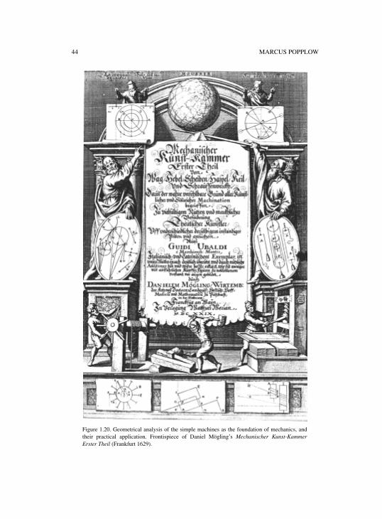
44 MARCUS POPPLOW
Figure 1.20. Geometrical analysis of the simple machines as the foundation of mechanics, andtheir practical application. Frontispiece of Daniel Mögling’s Mechanischer Kunst-KammerErster Theil (Frankfurt 1629).
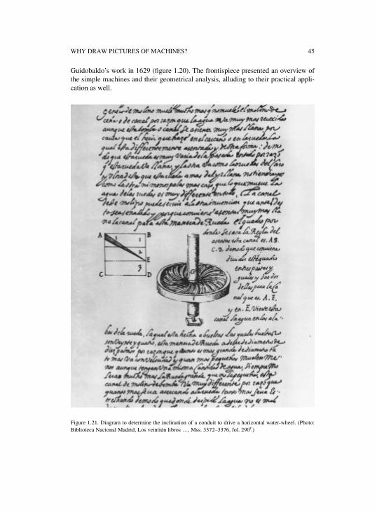
WHY DRAW PICTURES OF MACHINES? 45
Guidobaldo’s work in 1629 (figure 1.20). The frontispiece presented an overview ofthe simple machines and their geometrical analysis, alluding to their practical appli-cation as well.
Figure 1.21. Diagram to determine the inclination of a conduit to drive a horizontal water-wheel. (Photo:Biblioteca Nacional Madrid, Los veintiún libros …, Mss. 3372–3376, fol. 290r.)
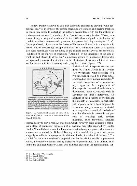
46 MARCUS POPPLOW
The few examples known to date that combined engineering drawings with geo-metrical analysis in terms of the simple machines are found in engineering treatises,in which they aimed to underline the author’s acquaintance with the foundations ofcontemporary science. The author of the Spanish engineering treatise “Twenty-onebooks of engineering and machines” in the 1570s thus analysed the inclination ofconduits to drive a water-wheel by means of a geometrical diagram (figure 1.21).47
Giuseppe Ceredi, physician to the Dukes of Parma and Piacenza, in a treatise pub-lished in 1567 concerning the application of the Archimedean screw to irrigation,also dealt extensively with the theory of the balance and the lever as the theoreticalfoundation of the analysis of machines.48 Arguing for the superiority of the kind ofcrank he had chosen to drive his Archimedean screws by manpower, Ceredi alsoincorporated geometrical abstractions in the illustration of his own solution in orderto allude to the scientific reasoning underlying his choice (figure 1.22).
A similar kind of explanation was latergiven by Simon Stevin in his treatise“De Weeghdaet” with reference to atypical crane operated by a tread-wheelemployed on early modern riversides.49
In private documents of sixteenth-cen-tury engineers, the employment ofdrawings for theoretical reflections isdocumented more extensively only inLeonardo da Vinci’s notebooks. Hisanalysis of such factors as friction andthe strength of materials, in particular,still appears to have been singular. Insixteenth-century manuscript material,no comparable theoretical analysis ofmachine elements is known. In the pro-cess of realizing early modernmachines, such theoretical analyses
seemed hardly to play a role. An exception, which, however, again concerns a prelim-inary stage of evaluating the design of a machine, was later reported by GalileoGalilei. While Galileo was at the Florentine court, a foreign engineer who remainedanonymous presented the Duke of Tuscany with a model of a geared mechanismallegedly suitable for employment in different kinds of mechanical devices.50 Thecrucial fact about the engineer’s proposal was that his device entailed a pendulum,which, the engineer claimed, greatly increased its performance. In an undated lettersent to the engineer, Galileo Galilei, who had been present at the demonstration, sub-
47 See Turriano 1996, fol. 290r.48 See Ceredi 1567.49 See Stevin 1955, 344.50 See Galilei 1968b.
Figure 1.22. Geometrical analysis in terms of thelever of a crank to drive an Archimedean screw.(Ceredi 1567, 67.)
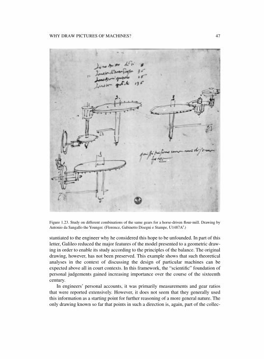
WHY DRAW PICTURES OF MACHINES? 47
Figure 1.23. Study on different combinations of the same gears for a horse-driven flour-mill. Drawing byAntonio da Sangallo the Younger. (Florence, Gabinetto Disegni e Stampe, U1487Ar.)
stantiated to the engineer why he considered this hope to be unfounded. In part of thisletter, Galileo reduced the major features of the model presented to a geometric draw-ing in order to enable its study according to the principles of the balance. The originaldrawing, however, has not been preserved. This example shows that such theoreticalanalyses in the context of discussing the design of particular machines can beexpected above all in court contexts. In this framework, the “scientific” foundation ofpersonal judgements gained increasing importance over the course of the sixteenthcentury.
In engineers’ personal accounts, it was primarily measurements and gear ratiosthat were reported extensively. However, it does not seem that they generally usedthis information as a starting point for further reasoning of a more general nature. Theonly drawing known so far that points in such a direction is, again, part of the collec-
48 MARCUS POPPLOW
tion of Antonio da Sangallo the Younger. It shows ways to combine identical gearingassembled differently in space, stating that they are all “of the same power”51 (figure1.23). This comment shows that in early modern engineering practice, concepts like“force” or “velocity” were used by engineers to describe the performance of suchdevices as a matter of course, without referring to the contemporary scientific defini-tions of these terms. Even if theoretical reasoning in mechanics did not emergedirectly from the use of such prescientific concepts, it seems obvious that the intensi-fied dissemination of preclassical mechanics towards the end of the sixteenth century,at least in Italy, sharpened the perception of the gaps between the scientific and thecolloquial use of such terms and thus further stimulated reasoning among figuresfamiliar with both cultures. Such gaps also became obvious with regard to the differ-ent visual grammars of engineering drawings and geometrical diagrams of preclassi-cal mechanics, which in the end concerned similar objects, namely basic machineelements. The merging of such different traditions of knowledge raised fruitful chal-lenges for the theoretical investigations in mechanics pursued, for example, byGuidobaldo del Monte and Galileo Galilei.
CONCLUSION
The preceding investigations have shown that early modern machine drawings are notonly relevant for the reconstruction of the state of the art of contemporary machinetechnology. Although an epistemic history of early modern engineering still remainsto be written, the analysis of the drawings technical experts produced testifies to thefact that their knowledge far exceeded the tacit knowledge of the artisan: Machinedrawings turn out to have been the product of a highly differentiated form of knowl-edge that could take on a number of functions in different contexts of employment.This is especially evident with regard to the drawings discussed here, which were, forthe most part, closely related to engineering practice. Such drawings open up newpossibilities of contextualizing Leonardo da Vinci’s drawings as well as those of themore representative machine books.
51 “[…] sono una medesima forza.” Frommel 1994c, 448.

PART IIPICTORIAL LANGUAGES AND SOCIAL
CHARACTERS

INTRODUCTION TO PART II
At first glance, almost all of the machine drawings of the fifteenth and sixteenth cen-turies may appear unprofessional to a modern beholder. They in no way resemble theorthographical plans and schematics that engineers trace and employ today. Usuallyomitting crucial details, often representing instead superfluous particulars of appar-ently rhetoric nature, and rarely giving measurements, they may even evoke the sus-picion that they are creations of interested laymen with limited competence asregards technological matters. Taking modern blueprints as standard, it is, indeed,hard to imagine that drawings of this kind were of any use for the practice of earlymodern engineers.
It is particularly the seemingly naiveté of these drawings that is misleading. Asthe chapters by David McGee and Rainer Leng show, these drawings are anything butnaïve. Even the most awkwardly drawn ones do not testify to unskilled attempts ofpractitioners groping for any manner of depicting intricate technical objects. Rather,such drawings testify to first experimental steps toward depicting them in a specificstyle of rendering that distinguishes early modern machine drawings from themachine drawings of the Middle Ages as well as those of the modern age.
The few extant machine drawings from the Middle Ages, which David McGeediscusses in the first part of his chapter, show a preceding style of technical drawingsreminiscent of modern schematics. Focusing exclusively on some of the essentialparts of a certain device and their arrangement, no effort is made to represent itsappearance. Because of this, they are often as unintelligible for a nonexpert as mod-ern engineering drawings. However, medieval technical drawings share one featurewith the seemingly naïve engineering drawings of the early modern period that dis-tinguishes them from modern ones. They, too, omit crucial details, do not give mea-surements, and leave the question of the device’s dimensions unanswered.
Against the background of this preceding style of machine rendering, two pointsbecome immediately clear. First, the early modern style of representing machineswas developed in a rejection of an earlier professional style of machine renderingand, thus, cannot be regarded as naïve and unprofessional itself. Second, the fact thatit shares with the preceding style a practice of neglecting crucial details, measure-ments, and dimensions, calls for a reconstruction of the engineering practice in theseages that accounts for the apparent usefulness of such incomplete drawings. Bothpoints together warn us not to judge the early modern machine drawings from theviewpoint of present engineering drawings. Rather, one has to try to interpret them intheir actual setting, that is, in the actual practice of early modern engineering.
The two chapters of part II do exactly this. They trace the origin and first develop-mental stages of the specific language of early modern machine drawings. The chap-ter by McGee explores the emergence of the new style with the Sienese engineerMariano di Jacopo, called Taccola, whose drawings constituted the starting point forthe Italian tradition of early modern engineering drawings, which became influentialfor the entire West. The chapter by Leng focuses on the less-known pictorial cata-logues of German master gun-makers from the fifteenth century. They are of particu-
52 INTRODUCTION TO PART II
lar interest with respect to the development of the language of early modern machinedrawings for two reasons. First, the bulk of them addresses exclusively fellowexperts; their pictorial language thus must have fit exactly the practical needs of thesepractitioners. Second, in these drawings, one can study how artificial views such ascutaways and exploded views were elaborated step by step.
Investigating carefully and in detail the pictorial means developed and employed,the two chapters inevitably lead to the social conditions that shaped the designing andmanufacturing of machines in the fifteenth century. And insights into these conditionslead, in turn, to a better understanding of the peculiarities of the new drawing style,which looked so strange at first glance. This style now appears as a highly artificialcompromise between the different ends these drawings had to fulfill at the same time,namely to present the device in question to nonexperts such as (potential) commis-sioners, on the one hand, and, on the other, to give the masters in charge of the (possi-ble) construction of the device all of the technical information they needed. Inreconstructing this double-faced nature of the early modern machine drawings, thesechapters restore to these drawings their genuine technical character, which is easilyeclipsed by their more obviously representational function for a contemporarybeholder.
2
THE ORIGINS OF EARLY MODERN MACHINE DESIGN
DAVID MCGEE
From approximately 1450 to 1750, machine designers made use of a singular kind ofgraphic representation. Where craftsmen used partial representations or none at all,and architects used plans and elevations to show different views of a building,machine designers stuck to a tradition of one drawing and one view for one machinein both sketches and presentations. Such a long and stable association betweenmachine design and one kind of drawing calls for explanation. This chapter attemptsto lay some of the groundwork for such an explanation through an investigation of theorigins of the early modern tradition of machine drawing in the period before 1450.
Any attempt to delve into the origins of early modern machine design is beset bymethodological problems. One set of these problems arises from the nature of theevidence. There are only a handful of extant manuscripts and they are spread acrossthree succeeding centuries. Such a distribution compels the historian of machinedesign to develop an account of long-term historical trends, with all the problems thatimplies, knowing that any such account can only rest on a slender foundation. Such apredicament generates a real need to get all we can out of the available evidence. Butdoing so is not easy. Early technical drawings are extraordinarily difficult to interpret.Confronted with a drawing from the fifteenth-century notebook of artist-engineerMariano Taccola (figure 2.1), for example, it is not at all clear what is important, whythese particular devices are found together, why they are drawn at different sizes, oreven what the drawings are for. Indeed, one rather quickly realizes that we simply donot have the conceptual tools we need to get at this kind of evidence.
A second set of problems is of our own making, beginning with our Platonicapproach to design, where design is taken to be a more or less entirely cognitive affairthat is concerned exclusively with the conception of form.1 Our tendency is to takedrawings as expressions of ideas, then move backwards from the drawings into theminds of the artists, either to describe what they were thinking, or, since knowingwhat they were thinking is almost impossible, to characterize their mentality, or toopine about cognition. This is to leap from the methodological frying pan into thefire, jumping from evidence we do not understand very well into the even moretreacherous realms of psychology—perhaps even to celebrate “tacit knowledge,” or“nonverbal thinking”—long before we have really come to grips with the evidence athand.2
1 A good example is Ferguson 1992. But the emphasis on conception and psychology is rampant in thedesign professions. See, for example, Lawson 1980; Akin 1986; and Rowe 1987.
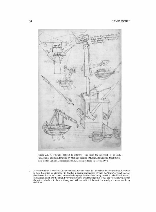
54 DAVID MCGEE
2 My concern here is twofold. On the one hand it seems to me that historians do a tremendous disserviceto their discipline by attempting to devolve historical explanation off onto the “truth” of psychologicaltheories (which are, of course, constantly changing), thereby abandoning the effort to build up historicalexplanation itself. On the other, I very much worry about theories that locate the essential evidence inthe mind, which is to base a theory on evidence which (like tacit knowledge) is unknowable bydefinition.
Figure 2.1. A typically difficult to interpret folio from the notebook of an earlyRenaissance engineer. Drawing by Mariano Taccola. (Munich, Bayerische Staatsbiblio-thek, Codex Latinus Monacensis 28800, f. 2r; reproduced in Taccola 1971.)
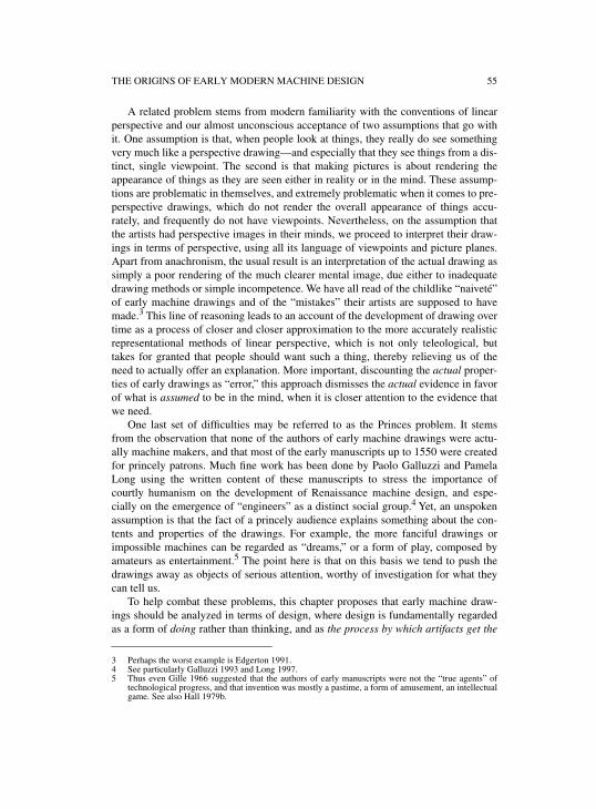
THE ORIGINS OF EARLY MODERN MACHINE DESIGN 55
A related problem stems from modern familiarity with the conventions of linearperspective and our almost unconscious acceptance of two assumptions that go withit. One assumption is that, when people look at things, they really do see somethingvery much like a perspective drawing—and especially that they see things from a dis-tinct, single viewpoint. The second is that making pictures is about rendering theappearance of things as they are seen either in reality or in the mind. These assump-tions are problematic in themselves, and extremely problematic when it comes to pre-perspective drawings, which do not render the overall appearance of things accu-rately, and frequently do not have viewpoints. Nevertheless, on the assumption thatthe artists had perspective images in their minds, we proceed to interpret their draw-ings in terms of perspective, using all its language of viewpoints and picture planes.Apart from anachronism, the usual result is an interpretation of the actual drawing assimply a poor rendering of the much clearer mental image, due either to inadequatedrawing methods or simple incompetence. We have all read of the childlike “naiveté”of early machine drawings and of the “mistakes” their artists are supposed to havemade.3 This line of reasoning leads to an account of the development of drawing overtime as a process of closer and closer approximation to the more accurately realisticrepresentational methods of linear perspective, which is not only teleological, buttakes for granted that people should want such a thing, thereby relieving us of theneed to actually offer an explanation. More important, discounting the actual proper-ties of early drawings as “error,” this approach dismisses the actual evidence in favorof what is assumed to be in the mind, when it is closer attention to the evidence thatwe need.
One last set of difficulties may be referred to as the Princes problem. It stemsfrom the observation that none of the authors of early machine drawings were actu-ally machine makers, and that most of the early manuscripts up to 1550 were createdfor princely patrons. Much fine work has been done by Paolo Galluzzi and PamelaLong using the written content of these manuscripts to stress the importance ofcourtly humanism on the development of Renaissance machine design, and espe-cially on the emergence of “engineers” as a distinct social group.4 Yet, an unspokenassumption is that the fact of a princely audience explains something about the con-tents and properties of the drawings. For example, the more fanciful drawings orimpossible machines can be regarded as “dreams,” or a form of play, composed byamateurs as entertainment.5 The point here is that on this basis we tend to push thedrawings away as objects of serious attention, worthy of investigation for what theycan tell us.
To help combat these problems, this chapter proposes that early machine draw-ings should be analyzed in terms of design, where design is fundamentally regardedas a form of doing rather than thinking, and as the process by which artifacts get the
3 Perhaps the worst example is Edgerton 1991.4 See particularly Galluzzi 1993 and Long 1997.5 Thus even Gille 1966 suggested that the authors of early manuscripts were not the “true agents” of
technological progress, and that invention was mostly a pastime, a form of amusement, an intellectualgame. See also Hall 1979b.
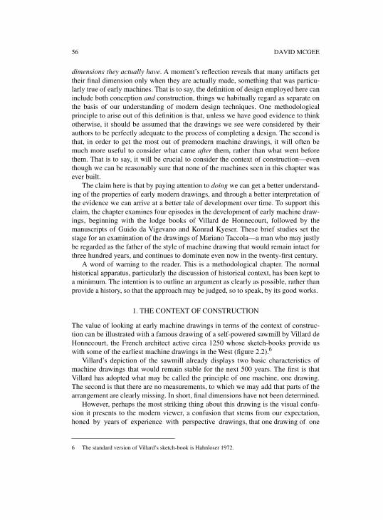
56 DAVID MCGEE
dimensions they actually have. A moment’s reflection reveals that many artifacts gettheir final dimension only when they are actually made, something that was particu-larly true of early machines. That is to say, the definition of design employed here caninclude both conception and construction, things we habitually regard as separate onthe basis of our understanding of modern design techniques. One methodologicalprinciple to arise out of this definition is that, unless we have good evidence to thinkotherwise, it should be assumed that the drawings we see were considered by theirauthors to be perfectly adequate to the process of completing a design. The second isthat, in order to get the most out of premodern machine drawings, it will often bemuch more useful to consider what came after them, rather than what went beforethem. That is to say, it will be crucial to consider the context of construction—eventhough we can be reasonably sure that none of the machines seen in this chapter wasever built.
The claim here is that by paying attention to doing we can get a better understand-ing of the properties of early modern drawings, and through a better interpretation ofthe evidence we can arrive at a better tale of development over time. To support thisclaim, the chapter examines four episodes in the development of early machine draw-ings, beginning with the lodge books of Villard de Honnecourt, followed by themanuscripts of Guido da Vigevano and Konrad Kyeser. These brief studies set thestage for an examination of the drawings of Mariano Taccola—a man who may justlybe regarded as the father of the style of machine drawing that would remain intact forthree hundred years, and continues to dominate even now in the twenty-first century.
A word of warning to the reader. This is a methodological chapter. The normalhistorical apparatus, particularly the discussion of historical context, has been kept toa minimum. The intention is to outline an argument as clearly as possible, rather thanprovide a history, so that the approach may be judged, so to speak, by its good works.
1. THE CONTEXT OF CONSTRUCTION
The value of looking at early machine drawings in terms of the context of construc-tion can be illustrated with a famous drawing of a self-powered sawmill by Villard deHonnecourt, the French architect active circa 1250 whose sketch-books provide uswith some of the earliest machine drawings in the West (figure 2.2).6
Villard’s depiction of the sawmill already displays two basic characteristics ofmachine drawings that would remain stable for the next 500 years. The first is thatVillard has adopted what may be called the principle of one machine, one drawing.The second is that there are no measurements, to which we may add that parts of thearrangement are clearly missing. In short, final dimensions have not been determined.
However, perhaps the most striking thing about this drawing is the visual confu-sion it presents to the modern viewer, a confusion that stems from our expectation,honed by years of experience with perspective drawings, that one drawing of one
6 The standard version of Villard’s sketch-book is Hahnloser 1972.
THE ORIGINS OF EARLY MODERN MACHINE DESIGN 57
Figure 2.2. Villard de Honnecourt’s drawing of a self-powered sawmill, c. 1225. (Detail of Paris,Bibliothèque Nationale de France, MS Fr 19093, f. 44; reproduced in Hahnloser 1972, plate 44.)
machine should also have one viewpoint. To us, Villard appears to have rotated dif-ferent parts of the sawmill away from their “true” position, relative to any viewpointand, moreover, has done so without any system. The timber seems to be shown fromthe top, the water-wheel from a three-quarters view, the saw blade from the side, thecams that bring the saw blade down from a different side, the tree-branch that bringsthe blade up from the side at one end but the top at the other, while the point at whichthe saw blade meets the timber seems to be shown from the top, side and three-quar-ters view all at once. We read the drawing as having multiple viewpoints at the sametime, some of them mutually exclusive. Hence the difficulty we have understandingthe picture.
Given our confusion, it is essential to point out that Villard can and does draw indifferent and (at least to us) “better” ways. In his architectural drawings, for example,Villard uses plans and elevations to show two sides of the same building in differentdrawings. Moreover, it turns out that Villard is also able to draw machines in a “bet-ter” way, as can be seen in his depiction of a new arrangement for fixing the hub of a
58 DAVID MCGEE
wagon without having to cut the shaft (figure 2.3). Here it appears that Villard mayeven have used a compass to construct a drawing that simultaneously shows both thetrue shape of the wheel and the way the arrangement would actually appear from oneside. With its apparent viewpoint, we read this drawing quite easily.7
The main point, however, is not whether one of Villard’s drawing styles is betterthan another, but recognition of the factthat Villard has different drawing stylesavailable to him. This immediatelyrules out interpretations of the styleused in the drawing of the sawmill as“naïve” or “childlike,” or indicative ofsome odd medieval way of “seeing” theworld (since if styles are equated withworld-views, then there are at leastthree world-views in Villard, which isridiculous).8 More important, acknowl-edging that Villard had different draw-ing styles available to him leads to therealization that he could have drawn hissawmill differently, and thus that hechose to depict the sawmill in the waythat he did.9 Evidently, he did sobecause he thought this style was bestfor his purpose.10 What purpose couldthat be?This is where consideration of the con-text of construction comes in, begin-ning with the fact that a machine like
Villard’s, like any machine of its kind at the time, would have to be adapted to the siteon which it was built. At different locations, the water-wheel would have to be of adifferent diameter, the drive shafts would have to be longer or shorter, the support
7 I say “apparent viewpoint” because the fact that the eye seems to be fixed at the center of the wheel maysimply have been the result of using a compass, and thus imply nothing about Villard having any notionof viewpoint, even though he was trying to depict the hub device as it would appear.
8 See for example, Booker 1963, and also Edgerton 1991.9 The importance of the availability of different styles of mechanical drawing for practitioners is also
noted by Marcus Popplow (this volume) in his discussion of the technical practice of HeinrichSchickhardt.
10 I forego what could be a lengthy discussion of why Villard, who may be taken to be indicative ofpremodern technical practice in general, uses different styles of drawings for different kinds of objects:the flat style for machines, plans and elevations and stonecutting diagrams for buildings, etc. I suggest,however, that part of the answer is to be found in the context of construction. There was a much greaterneed for precision in the construction of a building, whose parts must fit together precisely, than therewas in the construction of the wooden machinery of the Middle Ages. The need for precision implies agreater need to control the worker’s hands. Plans represent the first step in excercising that control,stonecutting drawings the next. As I suggest below, no such control over the hands of the machinemaker is wanted, but rather precisely the opposite.
Figure 2.3. Villard de Honnecourt’s drawing of awagon wheel. (Detail of Paris, Bibliothèque Natio-nale de France, MS Fr 19093, f. 45; reproduced inHahnloser, 1972, plate 45.)
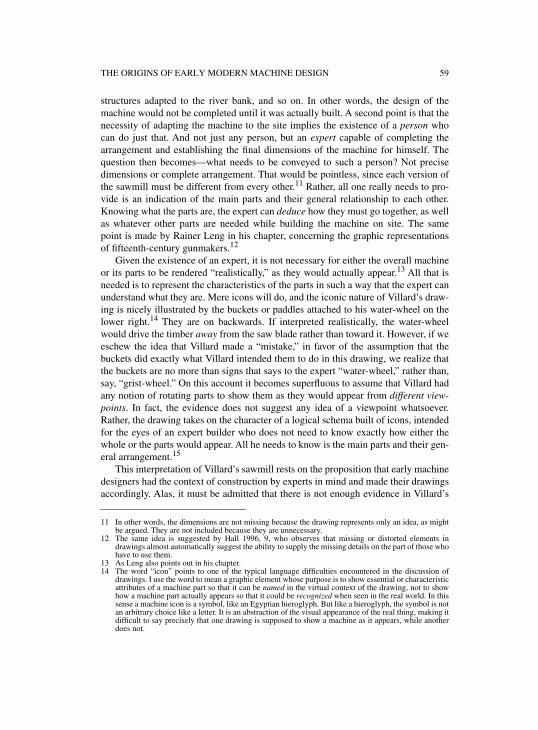
THE ORIGINS OF EARLY MODERN MACHINE DESIGN 59
structures adapted to the river bank, and so on. In other words, the design of themachine would not be completed until it was actually built. A second point is that thenecessity of adapting the machine to the site implies the existence of a person whocan do just that. And not just any person, but an expert capable of completing thearrangement and establishing the final dimensions of the machine for himself. Thequestion then becomes—what needs to be conveyed to such a person? Not precisedimensions or complete arrangement. That would be pointless, since each version ofthe sawmill must be different from every other.11 Rather, all one really needs to pro-vide is an indication of the main parts and their general relationship to each other.Knowing what the parts are, the expert can deduce how they must go together, as wellas whatever other parts are needed while building the machine on site. The samepoint is made by Rainer Leng in his chapter, concerning the graphic representationsof fifteenth-century gunmakers.12
Given the existence of an expert, it is not necessary for either the overall machineor its parts to be rendered “realistically,” as they would actually appear.13 All that isneeded is to represent the characteristics of the parts in such a way that the expert canunderstand what they are. Mere icons will do, and the iconic nature of Villard’s draw-ing is nicely illustrated by the buckets or paddles attached to his water-wheel on thelower right.14 They are on backwards. If interpreted realistically, the water-wheelwould drive the timber away from the saw blade rather than toward it. However, if weeschew the idea that Villard made a “mistake,” in favor of the assumption that thebuckets did exactly what Villard intended them to do in this drawing, we realize thatthe buckets are no more than signs that says to the expert “water-wheel,” rather than,say, “grist-wheel.” On this account it becomes superfluous to assume that Villard hadany notion of rotating parts to show them as they would appear from different view-points. In fact, the evidence does not suggest any idea of a viewpoint whatsoever.Rather, the drawing takes on the character of a logical schema built of icons, intendedfor the eyes of an expert builder who does not need to know exactly how either thewhole or the parts would appear. All he needs to know is the main parts and their gen-eral arrangement.15
This interpretation of Villard’s sawmill rests on the proposition that early machinedesigners had the context of construction by experts in mind and made their drawingsaccordingly. Alas, it must be admitted that there is not enough evidence in Villard’s
11 In other words, the dimensions are not missing because the drawing represents only an idea, as mightbe argued. They are not included because they are unnecessary.
12 The same idea is suggested by Hall 1996, 9, who observes that missing or distorted elements indrawings almost automatically suggest the ability to supply the missing details on the part of those whohave to use them.
13 As Leng also points out in his chapter.14 The word “icon” points to one of the typical language difficulties encountered in the discussion of
drawings. I use the word to mean a graphic element whose purpose is to show essential or characteristicattributes of a machine part so that it can be named in the virtual context of the drawing, not to showhow a machine part actually appears so that it could be recognized when seen in the real world. In thissense a machine icon is a symbol, like an Egyptian hieroglyph. But like a hieroglyph, the symbol is notan arbitrary choice like a letter. It is an abstraction of the visual appearance of the real thing, making itdifficult to say precisely that one drawing is supposed to show a machine as it appears, while anotherdoes not.
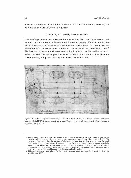
60 DAVID MCGEE
notebooks to confirm or refute this contention. Striking confirmation, however, canbe found in the work of Guido da Vigevano.
2. PARTS, PICTURES, AND PATRONS
Guido da Vigevano was an Italian medical doctor from Pavia who found service withvarious kings and queens of France in the fourteenth century. He is of interest herefor his Texaurus Regis Francae, an illustrated manuscript, which he wrote in 1335 toadvise Phillip VI of France on the conduct of a proposed crusade to the Holy Land.16
The first part of the manuscript concerns such things as proper diet and how to avoidbeing poisoned. The second part consists of 14 folios of text and drawings about thekind of military equipment the king would need to take with him.
Figure 2.4. Guido da Vigevano’s modular paddle boat, c. 1335. (Paris, Bibliothèque Nationale de France,Manuscrit latin 11015, Texaurus regis Francie aquisitionis terre sancte de ultra mare, f. 49r; reproduced inVigevano 1993, plate IX.)
15 The argument that drawings like Villard’s were understandable to experts naturally implies theexistence of a shared set of visual icons among those using the flat style in any given locale. Theexistence of such a set raises the question of what would happen if an item had to be indicated for whichthere was no icon, perhaps because it was entirely new. Without arguing the issue at length, it might besuggested that Villard’s spoke and hub represent one attempt to show a new item more realistically, asdoes the branch in his sawmill. Both, though in very different ways, might be seen as attempts to showunknown items as they would appear—perhaps the only alternative.
16 This expedition never took place. For the original text and marvelous reproductions of the drawings,see Vigevano 1993.
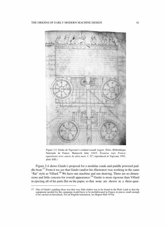
THE ORIGINS OF EARLY MODERN MACHINE DESIGN 61
Figure 2.4 shows Guido’s proposal for a modular crank-and-paddle powered pad-dle-boat.17 From it we see that Guido (and/or his illustrator) was working in the same“flat” style as Villard.18 We have one machine and one drawing. There are no dimen-sions and little concern for overall appearance.19 Guido is more rigorous than Villardin epicting all of his parts flat on the paper, so that none are shown in a three-quar-
17 One of Guido’s guiding ideas was that very little timber was to be found in the Holy Land so that theequipment needed for the campaign would have to be prefabricated in France in pieces small enoughto be carried on horseback. For an English translation, see Rupert Hall 1976a.
Figure 2.5. Guido da Vigevano’s cranked assault wagon. (Paris, BibliothèqueNationale de France, Manuscrit latin 11015, Texaurus regis Francieaquisitionis terre sancte de ultra mare, f. 51r; reproduced in Vigevano 1993,plate XIII.)
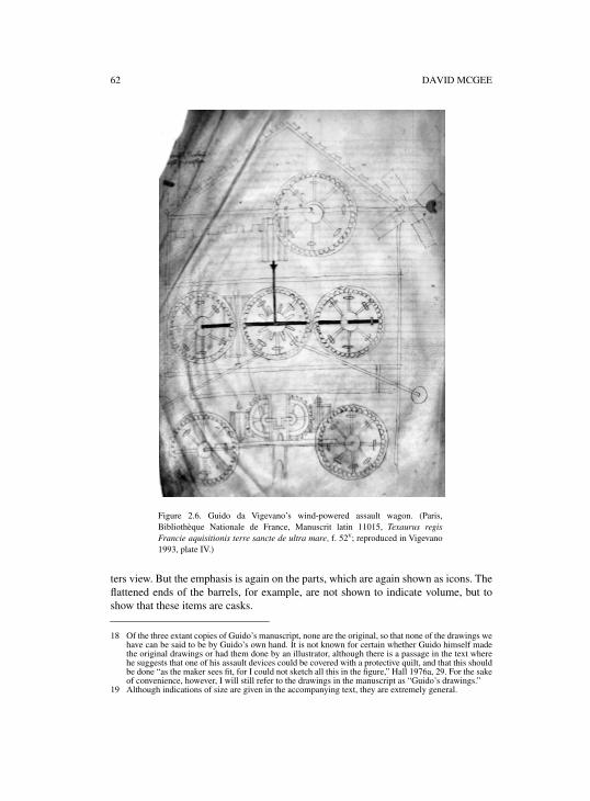
62 DAVID MCGEE
ters view. But the emphasis is again on the parts, which are again shown as icons. Theflattened ends of the barrels, for example, are not shown to indicate volume, but toshow that these items are casks.
18 Of the three extant copies of Guido’s manuscript, none are the original, so that none of the drawings wehave can be said to be by Guido’s own hand. It is not known for certain whether Guido himself madethe original drawings or had them done by an illustrator, although there is a passage in the text wherehe suggests that one of his assault devices could be covered with a protective quilt, and that this shouldbe done “as the maker sees fit, for I could not sketch all this in the figure,” Hall 1976a, 29. For the sakeof convenience, however, I will still refer to the drawings in the manuscript as “Guido’s drawings.”
19 Although indications of size are given in the accompanying text, they are extremely general.
Figure 2.6. Guido da Vigevano’s wind-powered assault wagon. (Paris,Bibliothèque Nationale de France, Manuscrit latin 11015, Texaurus regisFrancie aquisitionis terre sancte de ultra mare, f. 52v; reproduced in Vigevano1993, plate IV.)
THE ORIGINS OF EARLY MODERN MACHINE DESIGN 63
More important is what Guido says about the text associated with this drawing,which is that “a skilled man will easily understand this because I cannot write it moreclearly.”20 A few pages later, after describing the front wheels of his famous crank-powered assault wagon (figure 2.5), Guido observes that: “the rear wheels should besimilarly prepared in this way, and all these things shall be arranged by the mastermillwright who knows how to match these wheels together.”21 Similarly, referring tohis famous drawing of a wind-powered assault wagon (figure 2.6), Guido commentson his description of the gearing by saying that “all these matters are the concern ofthe master millwright and especially the master windmill-wright.”22 These passagesclearly show that, while writing his text and using the same style of drawing as Vil-lard, Guido was indeed thinking about the context of construction and particularlyabout construction by skilled experts. The last two passages make it explicit thatGuido believed his drawings would be fully comprehensible to these experts, and thathe fully expected them to be able to figure out from the drawings how to complete thedesign, deducing the necessary details from the arrangement of well known icons oflantern gears, cranks, and so on.23
It is worth stressing how different this design relationship is from that of today,where the designer is expected to provide complete drawings and complete specifica-tions of dimensions, parts, and arrangement, and the worker is expected to make theparts (and thus the machine) exactly as shown. But Guido not only expects the partic-ipation of expert machine builders, he needs them to make positive, creative contribu-tions. In fact, his text is full of comments to the effect that “whoever is to do this willprovide for the best,” and that various parts will be “made as those doing the job seefit.”24 In other words we see that medieval machine design was not conceived to be amatter of individual conception, of making a drawing and that was that. It was con-ceived as a process in which at least two people were needed to give a machine thefinal dimensions it would actually have when it was actually built. As in Villard, itwas not necessary, nor of any use, to provide dimensions or a realistic depiction ofthe overall machine to the experts who would build the machines and were quitecapable of determining final dimensions and arrangements for themselves. Flat,iconic representations would do.
However, in the very passages where Guido says his drawings will be perfectlyadequate for experts, he reveals that the flat, iconic style of the machine builders wasnot understandable to everyone—and particularly not to the ideal reader to whom the
20 Hall 1976a, 26.21 Ibid., 27.22 Ibid., 29.23 Having confirmed the idea of a style of drawings intended for expert makers, the question arises as to
the existence of a tradition of technical drawing in this style, stretching back in time. Lefèvre 2002 hasshown that whether or not one regards the illustrations as in any way original or authentic, the drawingsfound in military manuscript treatises on machines and mechanics prove that a flat style tradition ofmachine drawing existed in both the Byzantine and Arabic worlds from at least the early Middle Agesonward. His examples, as well as those in this chapter, show that there was considerable flexibility inthe application of this style, over and above its shared conventions.
24 To give a typical example, Guido writes that the platform of one of his assault towers is to be supportedby iron struts: “as the makers shall see fit, for it is not possible to set out every detail. But when someoneundertakes this work he will himself make provision for this platform.” Hall 1976a, 22.
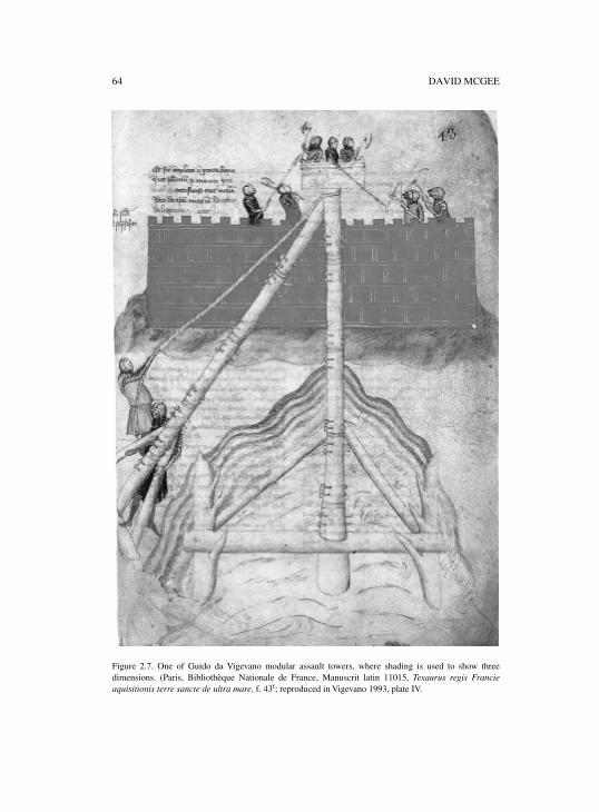
64 DAVID MCGEE
Figure 2.7. One of Guido da Vigevano modular assault towers, where shading is used to show threedimensions. (Paris, Bibliothèque Nationale de France, Manuscrit latin 11015, Texaurus regis Francieaquisitionis terre sancte de ultra mare, f. 43r; reproduced in Vigevano 1993, plate IV.
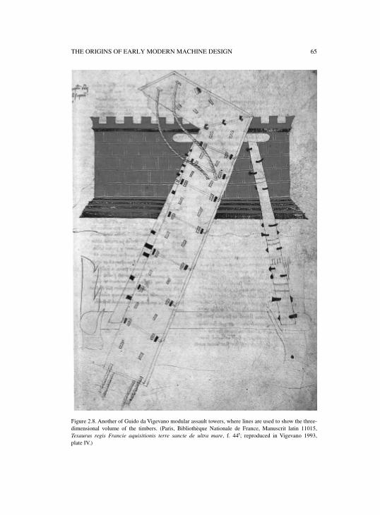
THE ORIGINS OF EARLY MODERN MACHINE DESIGN 65
Figure 2.8. Another of Guido da Vigevano modular assault towers, where lines are used to show the three-dimensional volume of the timbers. (Paris, Bibliothèque Nationale de France, Manuscrit latin 11015,Texaurus regis Francie aquisitionis terre sancte de ultra mare, f. 44r; reproduced in Vigevano 1993,plate IV.)
66 DAVID MCGEE
manuscript is dedicated, namely, his patron the King. This is significant because itpoints to Guido’s recognition of the participation of a third person in the design pro-cess: namely, the patron who may not determine any dimensions himself, but whoserole is nevertheless crucial, since without his approval, no money will be spent and nofinalization of the dimensions will ever take place.
In light of Guido’s awareness of the fact that the flat style created problems ofcommunication with patrons, two of his drawings may be singled out as particularlyimportant. The first shows an assault tower resting on three big legs, composed ofshort wooden modules held together by iron pins (figure 2.7).
The poles in this drawing are not represented by mere lines as the flat style woulddemand. Instead, shading has been added to give the poles three-dimensional volume,and thereby indicate that they are round. The second drawing (figure 2.8) shows amodular assault ramp, up which men are supposed to run until they reach the topmostsection, which they flip over the ramparts of the enemy fortress. Here, the ramp hasbeen drawn to show two sides of the modules at the same time, and lines have beendrawn in to indicate the volume of the modules without the use of shadowing.25 Inboth drawings we also notice that the machines have been set in scenes, with the for-tress being assaulted in the rear.
There would appear to be two possible explanations for this combination of set-ting and appearance, depending on the audience. It may be argued, for example, thatGuido’s goal was to show the purpose of his machines to the patron and that he setthem in their context of use in order to show what they were for. Since it would havebeen pointless to set the normal flat icons in such a setting, he therefore added thethird dimension to the parts in order to show everything as it would appear. Alter-nately, it may be argued that Guido’s modular ramps were quite new. Hence, therewere no icons for them in the established repertoire that could be used to communi-cate with the makers. Since there was no other choice, it was necessary to attempt toshow the parts as they would appear.26 The setting was added to help makers to iden-tify the parts by deduction from the purpose.
It seems most likely that both factors were in play, and that Guido was attemptingto find a means of communicating to both audiences at once. If so, these drawingsmay be taken to indicate the horns of the early machine designer’s dilemma. In tryingto show the appearance of his assault towers, Guido may have succeeded in giving abetter idea of their purpose, but his ability to show the parts to the expert/maker hassuffered. Without referring to the text, for example, it is extremely difficult to recog-nize the spikes or the modules for what they are.27
How to devise a style of representation that could answer the needs of bothmachine makers and patrons at once? This problem may be taken as one of the majordifficulties facing machine designers in the fourteenth and fifteenth centuries. A
25 Several more of Guido’s drawings also show three dimensions without shadowing.26 As noted above, the same may be seen in Villard’s drawing of a sawmill, where the tree branch used as
the return spring seems to be shown as it would appear, there being no standard mechanical icon forsuch a thing.
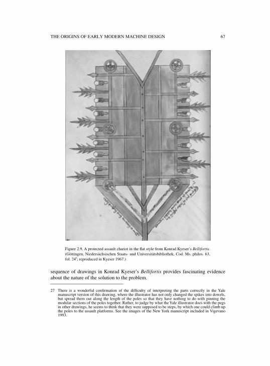
THE ORIGINS OF EARLY MODERN MACHINE DESIGN 67
sequence of drawings in Konrad Kyeser’s Bellifortis provides fascinating evidenceabout the nature of the solution to the problem.
27 There is a wonderful confirmation of the difficulty of interpreting the parts correctly in the Yalemanuscript version of this drawing, where the illustrator has not only changed the spikes into dowels,but spread them out along the length of the poles so that they have nothing to do with pinning themodular sections of the poles together. Rather, to judge by what the Yale illustrator does with the pegsin other drawings, he seems to think that they were supposed to be steps, by which one could climb upthe poles to the assault platforms. See the images of the New York manuscript included in Vigevano1993.
Figure 2.9. A protected assault chariot in the flat style from Konrad Kyeser’s Bellifortis.(Göttingen, Niedersächsischen Staats- und Universitätsbibliothek, Cod. Ms. philos. 63,fol. 24r; reproduced in Kyeser 1967.)
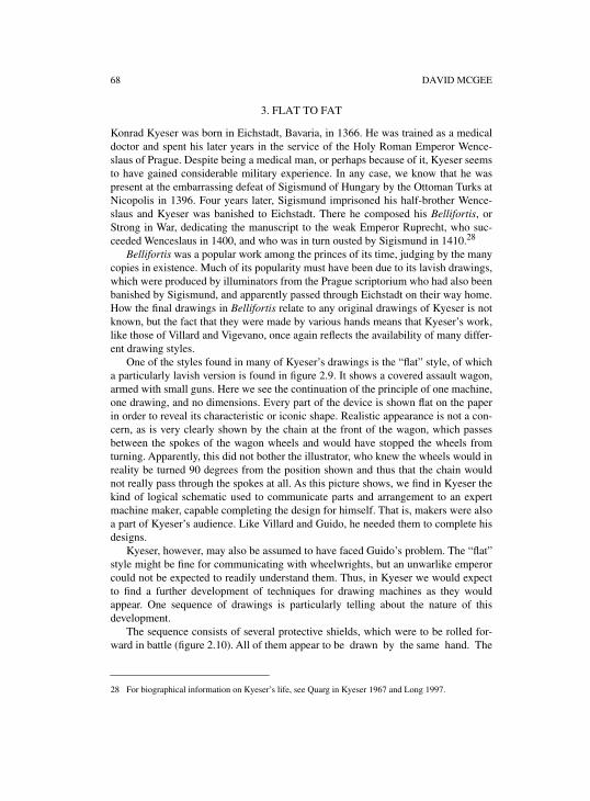
68 DAVID MCGEE
3. FLAT TO FAT
Konrad Kyeser was born in Eichstadt, Bavaria, in 1366. He was trained as a medicaldoctor and spent his later years in the service of the Holy Roman Emperor Wence-slaus of Prague. Despite being a medical man, or perhaps because of it, Kyeser seemsto have gained considerable military experience. In any case, we know that he waspresent at the embarrassing defeat of Sigismund of Hungary by the Ottoman Turks atNicopolis in 1396. Four years later, Sigismund imprisoned his half-brother Wence-slaus and Kyeser was banished to Eichstadt. There he composed his Bellifortis, orStrong in War, dedicating the manuscript to the weak Emperor Ruprecht, who suc-ceeded Wenceslaus in 1400, and who was in turn ousted by Sigismund in 1410.28
Bellifortis was a popular work among the princes of its time, judging by the manycopies in existence. Much of its popularity must have been due to its lavish drawings,which were produced by illuminators from the Prague scriptorium who had also beenbanished by Sigismund, and apparently passed through Eichstadt on their way home.How the final drawings in Bellifortis relate to any original drawings of Kyeser is notknown, but the fact that they were made by various hands means that Kyeser’s work,like those of Villard and Vigevano, once again reflects the availability of many differ-ent drawing styles.
One of the styles found in many of Kyeser’s drawings is the “flat” style, of whicha particularly lavish version is found in figure 2.9. It shows a covered assault wagon,armed with small guns. Here we see the continuation of the principle of one machine,one drawing, and no dimensions. Every part of the device is shown flat on the paperin order to reveal its characteristic or iconic shape. Realistic appearance is not a con-cern, as is very clearly shown by the chain at the front of the wagon, which passesbetween the spokes of the wagon wheels and would have stopped the wheels fromturning. Apparently, this did not bother the illustrator, who knew the wheels would inreality be turned 90 degrees from the position shown and thus that the chain wouldnot really pass through the spokes at all. As this picture shows, we find in Kyeser thekind of logical schematic used to communicate parts and arrangement to an expertmachine maker, capable completing the design for himself. That is, makers were alsoa part of Kyeser’s audience. Like Villard and Guido, he needed them to complete hisdesigns.
Kyeser, however, may also be assumed to have faced Guido’s problem. The “flat”style might be fine for communicating with wheelwrights, but an unwarlike emperorcould not be expected to readily understand them. Thus, in Kyeser we would expectto find a further development of techniques for drawing machines as they wouldappear. One sequence of drawings is particularly telling about the nature of thisdevelopment.
The sequence consists of several protective shields, which were to be rolled for-ward in battle (figure 2.10). All of them appear to be drawn by the same hand. The
28 For biographical information on Kyeser’s life, see Quarg in Kyeser 1967 and Long 1997.
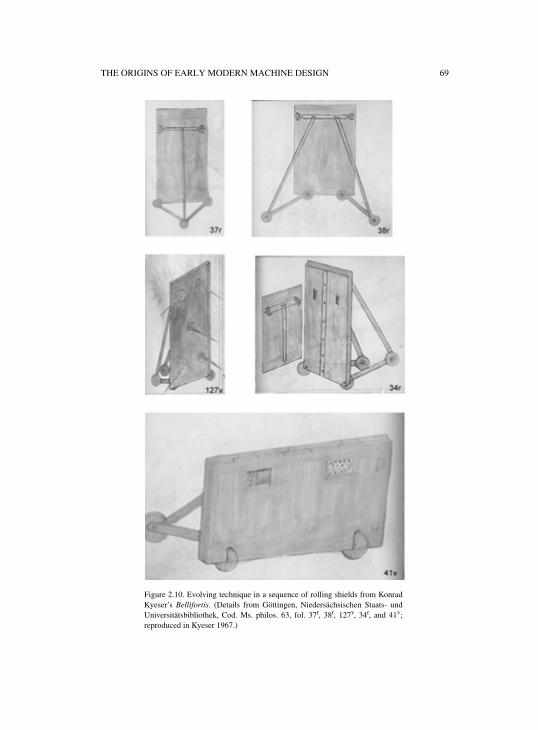
THE ORIGINS OF EARLY MODERN MACHINE DESIGN 69
Figure 2.10. Evolving technique in a sequence of rolling shields from KonradKyeser’s Bellifortis. (Details from Göttingen, Niedersächsischen Staats- undUniversitätsbibliothek, Cod. Ms. philos. 63, fol. 37r, 38r, 127v, 34r, and 41v;reproduced in Kyeser 1967.)
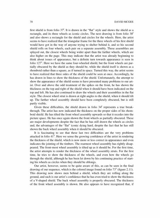
70 DAVID MCGEE
first shield is from folio 37r. It is drawn in the “flat” style and shows the shield as arectangle, and its three wheels as iconic circles. The next drawing is from folio 38r
and also shows a rectangle for the shield and circles for the wheels. Here, the artistseems to have realized that the triangular frame for the three wheels of his first shieldwould have got in the way of anyone trying to shelter behind it, and so his secondshield rolls on four wheels, each pair on a separate assembly. These assemblies aresplayed out, the closest wheels being wider apart than the farther wheels, which arealso higher on the page. This may indicate that the artist was already beginning tothink about issues of appearance, but a definite turn towards appearance is seen infolio 127v. Here we have the same four-wheeled shield, but the front wheels are par-tially obscured by the shield as they should be, while the shield itself is shown as arhomboid rather than a square, as if turned in space. Turned this way, the artist seemsto have realized that three sides of the shield could be seen at once. Accordingly, hehas drawn in lines to show the thickness of the shield. Unfortunately, the attempt toshow the appearance of the shield seems to have presented many problems to our art-ist. Over and above the odd treatment of the spikes on the front, he has shown thethickness on the top and right of the shield when it should have been indicated on thetop and left. He has also continued to draw the wheels and their assemblies in the flatstyle. The closest wheel strut is drawn at right angles to the shield, when it should tiltup. The farther wheel assembly should have been completely obscured, but is stillpartly visible.
Given these difficulties, the shield drawn in folio 34r represents a true break-through. The artist has now indicated the thickness on the proper sides of his rhom-boid shield. He has tilted the front wheel assembly upwards so that it recedes into thepicture space. He has once again shown the front wheels as partially obscured. Theseare major developments despite the fact that he has still drawn the wheels as circlesand, the advantages of the “flat” iconic dying hard, despite the fact that he has stillshown the back wheel assembly when it should be obscured.
It is fascinating to see that these last two difficulties are the very problemsattacked in folio 41v. Here we sense the growing confidence of the artist in renderingthe thickness of the shield, which is now more or less correct in appearance and evenindicates the jointing of the timbers. The rearmost wheel assembly has rightly disap-peared. The front-most wheel assembly is tilted up as it should be. For the first time,the artist attempts to render the thickness of the wheel assembly struts. For the firsttime, he tries to show the thickness of the wheels, and even how the wheels gothrough the shield, although he has been let down by his continuing practice of start-ing his wheels as circles when they should be oblongs.
Our artist, however, seems to be quite aware of this, as can be seen in the finaldrawing of our sequence, which is the colored image found on folio 73v (figure 2.11).This drawing now shows men behind a shield, which they are rolling along theground, and such is our artist’s confidence that he has even tried to show the thicknessof a V-shaped shield. The back wheel assembly is properly obscured. The thicknessof the front wheel assembly is shown. He also appears to have recognized that, if
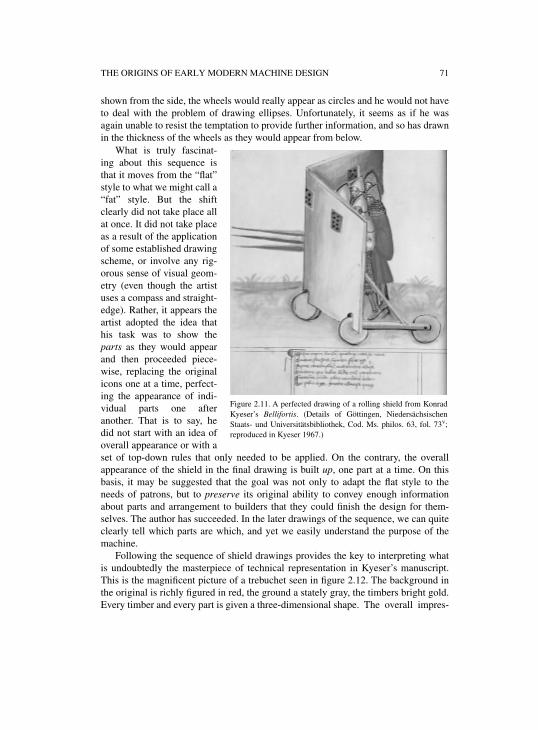
THE ORIGINS OF EARLY MODERN MACHINE DESIGN 71
shown from the side, the wheels would really appear as circles and he would not haveto deal with the problem of drawing ellipses. Unfortunately, it seems as if he wasagain unable to resist the temptation to provide further information, and so has drawnin the thickness of the wheels as they would appear from below.
What is truly fascinat-ing about this sequence isthat it moves from the “flat”style to what we might call a“fat” style. But the shiftclearly did not take place allat once. It did not take placeas a result of the applicationof some established drawingscheme, or involve any rig-orous sense of visual geom-etry (even though the artistuses a compass and straight-edge). Rather, it appears theartist adopted the idea thathis task was to show theparts as they would appearand then proceeded piece-wise, replacing the originalicons one at a time, perfect-ing the appearance of indi-vidual parts one afteranother. That is to say, hedid not start with an idea ofoverall appearance or with aset of top-down rules that only needed to be applied. On the contrary, the overallappearance of the shield in the final drawing is built up, one part at a time. On thisbasis, it may be suggested that the goal was not only to adapt the flat style to theneeds of patrons, but to preserve its original ability to convey enough informationabout parts and arrangement to builders that they could finish the design for them-selves. The author has succeeded. In the later drawings of the sequence, we can quiteclearly tell which parts are which, and yet we easily understand the purpose of themachine.
Following the sequence of shield drawings provides the key to interpreting whatis undoubtedly the masterpiece of technical representation in Kyeser’s manuscript.This is the magnificent picture of a trebuchet seen in figure 2.12. The background inthe original is richly figured in red, the ground a stately gray, the timbers bright gold.Every timber and every part is given a three-dimensional shape. The overall impres-
Figure 2.11. A perfected drawing of a rolling shield from KonradKyeser’s Bellifortis. (Details of Göttingen, NiedersächsischenStaats- und Universitätsbibliothek, Cod. Ms. philos. 63, fol. 73v;reproduced in Kyeser 1967.)
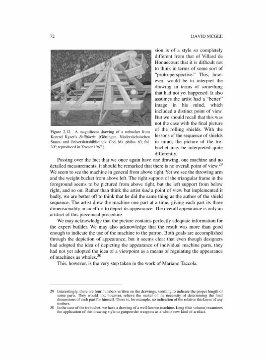
72 DAVID MCGEE
sion is of a style so completelydifferent from that of Villard deHonnecourt that it is difficult notto think in terms of some sort of“proto-perspective.” This, how-ever, would be to interpret thedrawing in terms of somethingthat had not yet happened. It alsoassumes the artist had a “better”image in his mind, whichincluded a distinct point of view.But we should recall that this wasnot the case with the final pictureof the rolling shields. With thelessons of the sequence of shieldsin mind, the picture of the tre-buchet may be interpreted quitedifferently.
Passing over the fact that we once again have one drawing, one machine and nodetailed measurements, it should be remarked that there is no overall point of view.29
We seem to see the machine in general from above right. Yet we see the throwing armand the weight bucket from above left. The right support of the triangular frame in theforeground seems to be pictured from above right, but the left support from belowright, and so on. Rather than think the artist had a point of view but implemented itbadly, we are better off to think that he did the same thing as the author of the shieldsequence. The artist drew the machine one part at a time, giving each part its threedimensionality in an effort to depict its appearance. The overall appearance is only anartifact of this piecemeal procedure.
We may acknowledge that the picture contains perfectly adequate information forthe expert builder. We may also acknowledge that the result was more than goodenough to indicate the use of the machine to the patron. Both goals are accomplishedthrough the depiction of appearance, but it seems clear that even though designershad adopted the idea of depicting the appearance of individual machine parts, theyhad not yet adopted the idea of a viewpoint as a means of regulating the appearanceof machines as wholes.30
This, however, is the very step taken in the work of Mariano Taccola.
29 Interestingly, there are four numbers written on the drawings, seeming to indicate the proper length ofsome parts. They would not, however, relieve the maker of the necessity of determining the finaldimensions of each part for himself. There is, for example, no indication of the relative thickness of anytimbers.
30 In the case of the trebuchet, we have a drawing of a well-known machine. Leng (this volume) examinesthe application of this drawing style to gunpowder weapons as a whole new kind of artifact.
Figure 2.12. A magnificent drawing of a trebuchet fromKonrad Kyser’s Bellifortis. (Göttingen, NiedersächsischenStaats- und Universitätsbibliothek, Cod. Ms. philos. 63, fol.30r; reproduced in Kyeser 1967.)
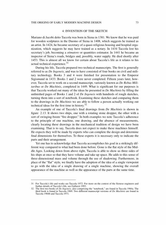
THE ORIGINS OF EARLY MODERN MACHINE DESIGN 73
4. INVENTION OF THE SKETCH
Mariano di Jacobi detto Taccola was born in Siena in 1381. We know that he was paidfor wooden sculptures in the Duomo of Siena in 1408, which suggests he trained asan artist. In 1424, he became secretary of a quasi-religious housing and hospital orga-nization, which suggests he may have trained as a notary. In 1434 Taccola lost hissecretary’s job, becoming a stimatore or quantities estimator. In 1441 he became aninspector of Siena’s roads, bridges and, possibly, water supply. He died shortly after1453. This is almost all we know for certain about Taccola’s life as it relates to hisactual technical experience.31
During his life, Taccola prepared two technical manuscripts. The first is generallyreferred to as De Ingeneis, and was to have consisted of four books on civil and mili-tary technology. Books 3 and 4 were finished for presentation to the EmperorSigismund in 1433. Books 1 and 2 were never completed. Fifteen years later, how-ever, Taccola set to work on a second manuscript, variously known as De Rebus Mili-taribus or De Machinis, completed in 1449. What is significant for our purposes isthat Taccola worked out many of the ideas he presented in De Machinis by filling theunfinished pages of Books 1 and 2 of De Ingeneis with hundreds of rough sketches,turning them into a sort of notebook. Examining these sketches and comparing themto the drawings in De Machinis we are able to follow a person actually working outtechnical ideas for the first time in history.32
An example of one of Taccola’s final drawings from De Machinis is shown infigure 2.13. It shows two ships, one with a rotating stone dropper, the other with asort of swinging-boom “fire dropper.” In both examples we note Taccola’s adherenceto the principle of one machine, one drawing, and the absence of measurements,clearly locating these drawings in the mechanical tradition of design we have beenexamining. That is to say, Taccola does not expect to make these machines himself.He expects they will be made by experts who can complete the design and determinefinal dimensions for themselves. To these experts it is necessary only to indicate theparts and their arrangement.
Yet one has to acknowledge that Taccola accomplishes his goal in a strikingly dif-ferent way compared to what had been done before. Gone is the flat style of the Mid-dle Ages. Looking down from above right, Taccola is able to show us three sides ofhis ships at once so that they have volume and take up space. He adds to this sense ofthree-dimensional mass and volume through the use of shadowing. Furthermore, inplace of the “flat” style, we finally have the adoption of the idea of a single viewpointto go with the idea of a single drawing of a single machine, showing the overallappearance of the machine as well as the appearance of the parts at the same time.
31 For Taccola’s life and works see Taccola 1972. For more on the context of the Sienese engineers andfurther details of Taccola’s life, see Galluzzi 1993.
32 The first two books of De Ingeneis, also comprising the “notebook,” are found in Taccola 1984a. Thethird book is found in Taccola 1969. Two different manuscript versions of De Machinis are found inTaccola 1984b and Taccola 1971.

74 DAVID MCGEE
Figure 2.13. A page from Mariano Taccola’s De Machinis of 1449. (Munich, Bayerische Staatsbibliothek,Codex Latinus Monacensis 28800, fol. 94r; reproduced in Taccola 1971.)
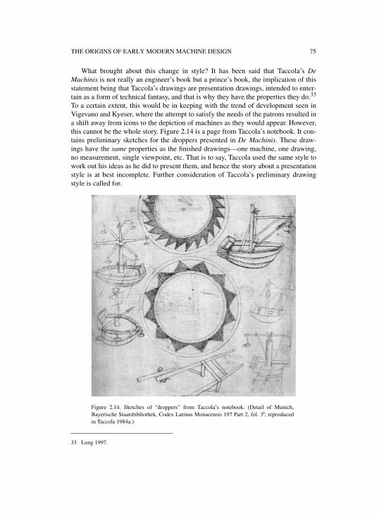
THE ORIGINS OF EARLY MODERN MACHINE DESIGN 75
What brought about this change in style? It has been said that Taccola’s DeMachinis is not really an engineer’s book but a prince’s book, the implication of thisstatement being that Taccola’s drawings are presentation drawings, intended to enter-tain as a form of technical fantasy, and that is why they have the properties they do.33
To a certain extent, this would be in keeping with the trend of development seen inVigevano and Kyeser, where the attempt to satisfy the needs of the patrons resulted ina shift away from icons to the depiction of machines as they would appear. However,this cannot be the whole story. Figure 2.14 is a page from Taccola’s notebook. It con-tains preliminary sketches for the droppers presented in De Machinis. These draw-ings have the same properties as the finished drawings—one machine, one drawing,no measurement, single viewpoint, etc. That is to say, Taccola used the same style towork out his ideas as he did to present them, and hence the story about a presentationstyle is at best incomplete. Further consideration of Taccola’s preliminary drawingstyle is called for.
33 Long 1997.
Figure 2.14. Sketches of “droppers” from Taccola’s notebook. (Detail of Munich,Bayerische Staatsbibliothek, Codex Latinus Monacensis 197 Part 2, fol. 3r; reproducedin Taccola 1984a.)
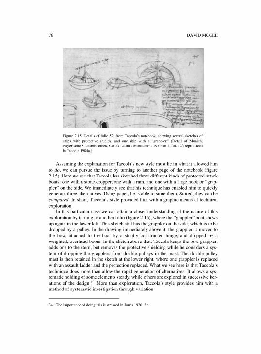
76 DAVID MCGEE
Assuming the explanation for Taccola’s new style must lie in what it allowed himto do, we can pursue the issue by turning to another page of the notebook (figure2.15). Here we see that Taccola has sketched three different kinds of protected attackboats: one with a stone dropper, one with a ram, and one with a large hook or “grap-pler” on the side. We immediately see that his technique has enabled him to quicklygenerate three alternatives. Using paper, he is able to store them. Stored, they can becompared. In short, Taccola’s style provided him with a graphic means of technicalexploration.
In this particular case we can attain a closer understanding of the nature of thisexploration by turning to another folio (figure 2.16), where the “grappler” boat showsup again in the lower left. This sketch still has the grappler on the side, which is to bedropped by a pulley. In the drawing immediately above it, the grappler is moved tothe bow, attached to the boat by a stoutly constructed hinge, and dropped by aweighted, overhead boom. In the sketch above that, Taccola keeps the bow grappler,adds one to the stern, but removes the protective shielding while he considers a sys-tem of dropping the grapplers from double pulleys in the mast. The double-pulleymast is then retained in the sketch at the lower right, where one grappler is replacedwith an assault ladder and the protection replaced. What we see here is that Taccola’stechnique does more than allow the rapid generation of alternatives. It allows a sys-tematic holding of some elements steady, while others are explored in successive iter-ations of the design.34 More than exploration, Taccola’s style provides him with amethod of systematic investigation through variation.
34 The importance of doing this is stressed in Jones 1970, 22.
Figure 2.15. Details of folio 52r from Taccola’s notebook, showing several sketches ofships with protective shields, and one ship with a “grappler.” (Detail of Munich,Bayerische Staatsbibliothek, Codex Latinus Monacensis 197 Part 2, fol. 52r; reproducedin Taccola 1984a.)
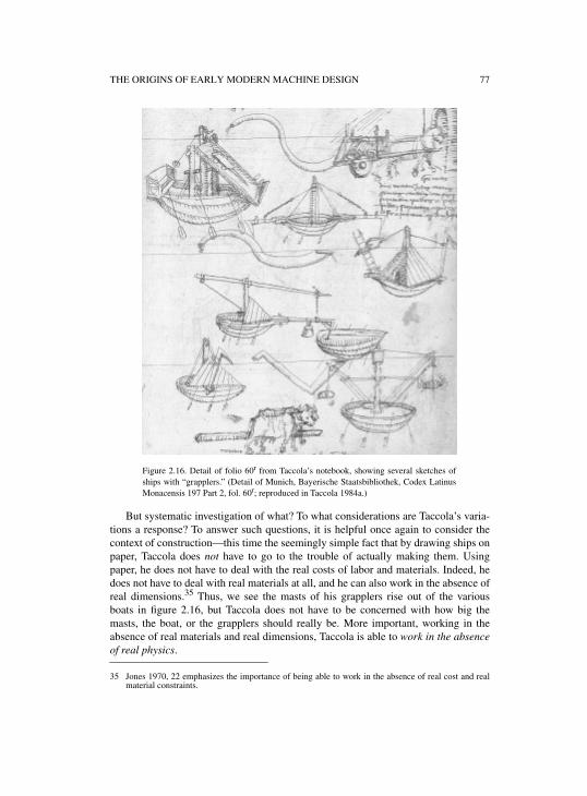
THE ORIGINS OF EARLY MODERN MACHINE DESIGN 77
But systematic investigation of what? To what considerations are Taccola’s varia-tions a response? To answer such questions, it is helpful once again to consider thecontext of construction—this time the seemingly simple fact that by drawing ships onpaper, Taccola does not have to go to the trouble of actually making them. Usingpaper, he does not have to deal with the real costs of labor and materials. Indeed, hedoes not have to deal with real materials at all, and he can also work in the absence ofreal dimensions.35 Thus, we see the masts of his grapplers rise out of the variousboats in figure 2.16, but Taccola does not have to be concerned with how big themasts, the boat, or the grapplers should really be. More important, working in theabsence of real materials and real dimensions, Taccola is able to work in the absenceof real physics.
35 Jones 1970, 22 emphasizes the importance of being able to work in the absence of real cost and realmaterial constraints.
Figure 2.16. Detail of folio 60r from Taccola’s notebook, showing several sketches ofships with “grapplers.” (Detail of Munich, Bayerische Staatsbibliothek, Codex LatinusMonacensis 197 Part 2, fol. 60r; reproduced in Taccola 1984a.)
78 DAVID MCGEE
In the absence of materials, dimensions, and physics, Taccola is able to iteratefreely, in both senses of the word. There is no cost of construction and no cost of fail-ure. He is not constrained as the expert maker would be. However, the absence ofphysics makes it clear that Taccola’s variations in design did not result from the con-sideration of physical problems related to issues in mechanics. The information nec-essary for any such considerations is just what is missing. For instance, given theabsence of dimensions, he could not know either factually or intuitively whether hisboats would have the necessary displacement to float themselves, let alone to carrythe equipment and protection he proposes, with adequate stability. Indeed, in theabsence of dimensions, he could not even calculate the problem of the levers aroundwhich all his designs are organized.36
Instead, it appears that Taccola’s drawing technique allows him to pass beyond thecontext of construction to investigate the future context of use. Thus, there is nothingphysically impossible about placing the grappler on the side of a boat, as Taccoladoes in his initial sketches (figure 2.16). The pulley arrangement would work. But itis not very likely to be effective in battle, particularly if the enemy ship approachesfrom the other side. Seemingly aware of this, in his next sketch Taccola considersdropping the grappler from the bow, which could be more effective, although thestern would be unprotected. Hence, the double-grappler of his next drawing. Simi-larly, there is nothing physically better about dropping grappling hooks from over-head beams, as opposed to pulleys, or double pulleys. Again, the cause of variationappears to be Taccola’s awareness of awkwardness or ineffectiveness for the humanswho actually have to use them.37
It may be significant that this process of systematic variation, iteration, and explo-ration of the context of use continues into the final drawings of De Machinis. Thus, infigure 2.17 we have what almost looks like the original design, but with a grappler atthe front using his perfected hinge arrangement and the pulley dropper. In figure 2.18we have a sort of grappler and assault ladder combined, but a more sensible form ofprotection than the original pyramid. In figure 2.19 we have a ladder and grapplercombination, with a flat deck for protection, while double pulleys on one mast havebeen abandoned for double masts with a single pulley each. Such a sequence of draw-ings flowing from the notebook to De Machinis strongly suggests that Taccola’s “pre-sentation” drawings are actually an extension of his investigative technique, ratherthan the reverse. If so, it would be possible to argue that Taccola developed his inno-
36 One might claim that Taccola varied his design in response to his intuitive understanding of mechanicalproblems. My response is not to say that this is impossible, but rather that is an argument for whichthere can be no proof, because the whole advantage of the only evidence available—the drawings—isthat they eliminate the need for physical considerations on the part of the artist.
37 It may be argued here that I have violated my own injunction and started to discuss what Taccola wasthinking. There is a difference, however. Following the approach presented in this paper, one is able todescribe Taccola’s thinking as sequence of reasoning, and moreover to point to the evidence forassertions about that reasoning. This is quite different from opining about “cognition,” or “tacit”knowledge, particularly in that one can argue about the actual evidence at hand, and not about humannature, whether one particular psychological theory is valid and so on. With more space, I would furtherargue that, while doing may not always be regarded as thinking, thinking may always be regarded as aform of doing.
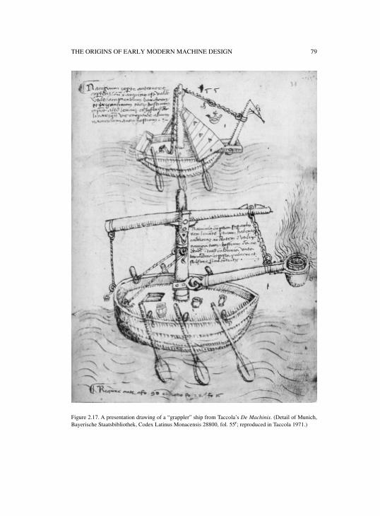
THE ORIGINS OF EARLY MODERN MACHINE DESIGN 79
Figure 2.17. A presentation drawing of a “grappler” ship from Taccola’s De Machinis. (Detail of Munich,Bayerische Staatsbibliothek, Codex Latinus Monacensis 28800, fol. 55r; reproduced in Taccola 1971.)
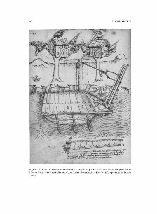
80 DAVID MCGEE
Figure 2.18. A second presentation drawing of a “grappler” ship from Taccola’s De Machinis. (Detail fromMunich, Bayerische Staatsbibliothek, Codex Latinus Monacensis 28800, fol. 81v; reproduced in Taccola1971.)
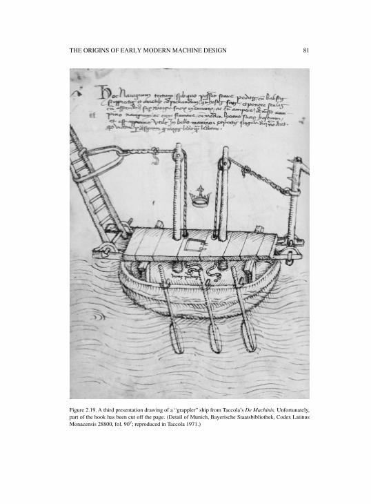
THE ORIGINS OF EARLY MODERN MACHINE DESIGN 81
Figure 2.19. A third presentation drawing of a “grappler” ship from Taccola’s De Machinis. Unfortunately,part of the hook has been cut off the page. (Detail of Munich, Bayerische Staatsbibliothek, Codex LatinusMonacensis 28800, fol. 90v; reproduced in Taccola 1971.)
82 DAVID MCGEE
vative drawing style precisely because of the investigation it involved, rather than forits presentation value. In the larger picture, however, we may at least say that Tac-cola’s search for a means to satisfy the visual needs of his patrons had a momentous,but unexpected result—a graphic technique for investigation and invention that wassoon, in the hands of Francesco di Giorgio Martini, Leonardo da Vinci, and others, tobecome crucial to the development of mechanical technology in the West.
The question arises, of course, as to whether Taccola’s technique was really new.Artists of the Middle Ages used representations of appearance to show chairs andbuildings, as did the Romans. But we have no evidence to show that they used thetechnique to work out mechanical ideas. Is this because they did not do so? Orbecause the evidence is lost? My own opinion is that the technique used by Taccola isnew in its application to machine design, and the evidence suggests he adopted itbecause of the kind of mechanical investigations it allowed.38 Indeed, it may even bethe reason for the great interest in Taccola’s manuscript by those who consulted andcopied it, including Giorgio Martini and Leonardo—not for the machinery depicted,but for the revolutionary manner of depicting the machinery.
5. THE SOCIAL GROUNDS OF CREATIVITY
This chapter began with a question about the stable relationship between machinedesign and the use of one machine, one view drawings over the period 1400 to 1750.We are now in a position to explain this relationship in terms of the creation of a pow-erful “paper tool” in the early decades of the fifteenth century, as used by Taccola, ifnot created by him.39
To be sure, the use of one drawing for one machine was already part of a traditionstretching back into the Arabic and Byzantine past, when the flat style could be usedto communicate to workers, and perhaps to the learned readers of ancient treatises onmechanics.40 But in the fifteenth century, a switch away from logical schema towardsthe depiction of appearance, followed by the adoption of the viewpoint (before theinvention or at least diffusion of linear perspective), resulted in the creation of a styleof drawing that could do three things at once. First, it continued to supply enoughinformation to expert makers that a machine could be constructed, even though thenew kind of drawing was no more complete than those made in the flat style.41 Sec-ond, the new kind of drawing provided information that was comprehensible topatrons, demonstrating not only the mechanical working of the machine, but its pur-pose, and its method of use. Third, as is clear from Taccola’s notebook, the newmethod provided a new and powerful tool of investigation. Not a tool of invention,
38 Although its origins may lie in the painterly techniques of Giotto and Duccio. If so, then we might lookto explain Taccola’s use of his technique in terms of the artists’ timely possession of a new kind of toolin a changing context of patronage, where both machine building in the service of the state andhumanistic investigations of ancient technologies were extremely serious business.
39 See Goody 1977, and Klein 2003.40 Again see Lefèvre 2002. But also see Hill 1996, and Jazari 1974. 41 As Popplow points out in his chapter, even Schickhardt’s highly detailed drawings intended for his
workers left out critical information about gears.
THE ORIGINS OF EARLY MODERN MACHINE DESIGN 83
one should be careful to say, since Vigevano was clearly capable of inventing in theflat style, but certainly a tool of more rapid investigation of combinations and theiruse in future contexts. The somewhat halting development of rolling shields inKyeser’s manuscript, as opposed to Tacola’s rapid development of several kinds ofassault ships, is illustrative.
Another issue raised in the introduction was the “Princes problem,” arising fromthe fact that many early manuscripts were intended for a princely audience. What wasthe effect of this audience on mechanical drawings? The explanation offered here isthat the need to communicate more clearly with patrons drove a change from thedepiction of logical, iconic schemas to the depiction of appearance. This developmentwas under way before the invention of linear perspective. However, this was not theonly factor in play. The evidence of Kyeser’s Bellifortis suggests that the method ofdepiction was not simply borrowed from existing courtly styles of painting and illu-mination. Rather, as the sequence of rolling shields suggests, the method of depictionhad to be worked out, step after step. But as the drawings in Kyeser’s manuscript alsoshow, one of the most important constraints on the development of the new style wasthe need to preserve the ability to communicate parts and arrangement to makers. It isnot that there was only one audience for these drawings. There were always two.42
This chapter also started with a plea for coming to grips analytically with the evi-dence provided by the properties of early machine drawing. I’ve tried to show thatthere can be a benefit in doing so, in the form of three perhaps surprising results.
One surprise is that, although we tend to regard drawings as evidence of thinking,as extensions of cognitive processes of design in the mind’s eye, the properties ofearly machine drawings actually point more immediately to what might be referred toas a social process of design in which the second person is the real expert, the personwho actually determines the final dimensions of the machine that is made. This is afundamental context of machine design that would remain the same for several centu-ries after Taccola. Indeed, mechanical drawing would only begin to change in the lateeighteenth century when the shift from wood to metal, and the holy grail of replace-able parts, set off a determined attempt to gain control over the hands of machinemakers.43
The second surprise is the methodological one, in which consideration of the con-text of construction proves to be crucial to understanding the properties of themachine drawings we see—even though it may well be that the machines were nevermade. This is important, because we truly need to remind ourselves that design draw-ings are really about what is to happen after them, not what went before them. It is inthis context of what will happen that they are made. Surely it ought to be important intrying to interpret them.
The third surprise follows from an examination of Taccola’s use of drawings toinvestigate new kinds of machines, investigations that seem much closer to the cogni-
42 This only makes sense, since a prince might at any time order a machine from a manuscript to be built,and the authors of drawings were, in most cases, not capable of actually building machines themselves.
43 See the discussions in Alder 1997; Baynes and Pugh 1981; Noble 1984; Smith 1977.
84 DAVID MCGEE
tive processes of design as we normally conceive them. But even here, considerationof construction proves important, leading to the realization that Taccola used thesedrawings precisely because they meant he did not have to build experimentalmachines, but was free to innovate as he pleased precisely because he was able towork in the absence of the real constraints of dimensions, materials, labor and phys-ics.
Now on the one hand, it seems to me that the absence of physical considerationsin the drawings creates big problems for anyone hoping to conscript Taccola andother early artist-engineers as conceptual builders of the scientific revolution. Neitherformal physics nor even intuitive physics are there in the evidence. On the other hand,it seems to me that the lack of physics and the evident impossibility of many earlymachine drawings has often misled us into thinking that they are merely forms of cre-ative play, fantasy—in other words, just fooling around.
There is, however, another way to look at it. If we bring our expert maker backinto the design process, we realize that real constraints are not actually gone, so muchas displaced into the future—and, particularly, that they are displaced onto the shoul-ders of another person. It is the job of the expert builder not only to make themachine, but to make it work, meaning that dealing with the physics was the problemof the builder, and not of someone like Taccola. If so, and if it is the absence of con-straints that is the key to innovation on paper, it is possible to suggest that the socialsituation was the very ground of the individual creativity we see in early machinedrawings, and that it was the recognized existence of expert makers (so often dispar-aged as mere craftsmen) that created the very space in which the Renaissance designof machines on paper was possible.
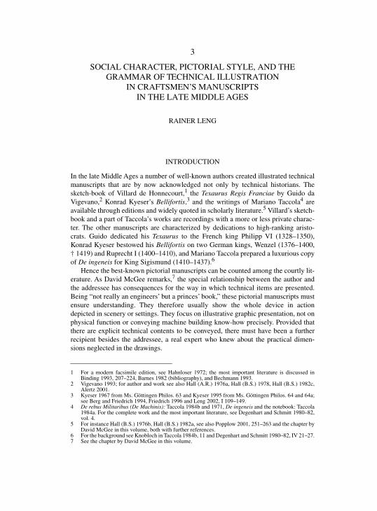
3
SOCIAL CHARACTER, PICTORIAL STYLE, AND THE GRAMMAR OF TECHNICAL ILLUSTRATION
IN CRAFTSMEN’S MANUSCRIPTSIN THE LATE MIDDLE AGES
RAINER LENG
INTRODUCTION
In the late Middle Ages a number of well-known authors created illustrated technicalmanuscripts that are by now acknowledged not only by technical historians. Thesketch-book of Villard de Honnecourt,1 the Texaurus Regis Franciae by Guido daVigevano,2 Konrad Kyeser’s Bellifortis,3 and the writings of Mariano Taccola4 areavailable through editions and widely quoted in scholarly literature.5 Villard’s sketch-book and a part of Taccola’s works are recordings with a more or less private charac-ter. The other manuscripts are characterized by dedications to high-ranking aristo-crats. Guido dedicated his Texaurus to the French king Philipp VI (1328–1350),Konrad Kyeser bestowed his Bellifortis on two German kings, Wenzel (1376–1400,† 1419) and Ruprecht I (1400–1410), and Mariano Taccola prepared a luxurious copyof De ingeneis for King Sigismund (1410–1437).6
Hence the best-known pictorial manuscripts can be counted among the courtly lit-erature. As David McGee remarks,7 the special relationship between the author andthe addressee has consequences for the way in which technical items are presented.Being “not really an engineers’ but a princes’ book,” these pictorial manuscripts mustensure understanding. They therefore usually show the whole device in actiondepicted in scenery or settings. They focus on illustrative graphic presentation, not onphysical function or conveying machine building know-how precisely. Provided thatthere are explicit technical contents to be conveyed, there must have been a furtherrecipient besides the addressee, a real expert who knew about the practical dimen-sions neglected in the drawings.
1 For a modern facsimile edition, see Hahnloser 1972; the most important literature is discussed inBinding 1993, 207–224, Barnes 1982 (bibliography), and Bechmann 1993.
2 Vigevano 1993; for author and work see also Hall (A.R.) 1976a, Hall (B.S.) 1978, Hall (B.S.) 1982c,Alertz 2001.
3 Kyeser 1967 from Ms. Göttingen Philos. 63 and Kyeser 1995 from Ms. Göttingen Philos. 64 and 64a;see Berg and Friedrich 1994, Friedrich 1996 and Leng 2002, I 109–149.
4 De rebus Militaribus (De Machinis): Taccola 1984b and 1971, De ingeneis and the notebook: Taccola1984a. For the complete work and the most important literature, see Degenhart and Schmitt 1980–82,vol. 4.
5 For instance Hall (B.S.) 1976b, Hall (B.S.) 1982a, see also Popplow 2001, 251–263 and the chapter byDavid McGee in this volume, both with further references.
6 For the background see Knobloch in Taccola 1984b, 11 and Degenhart and Schmitt 1980–82, IV 21–27.7 See the chapter by David McGee in this volume.
86 RAINER LENG
This specific tradition of explaining technology for high-ranking laymen bymeans of drawings can be found throughout the entire fifteenth century. Besides thewell-known books mentioned, this is also apparent in two unpublished manuscriptsdealing with the art of warfare, which were produced for the emperors Sigismund(1410–1437) and Frederick III (1440–1495).8 Even the first printed technical book—Roberto Valturio’s De re militari, dedicated to Sigismundo Pandulfo Malatesta(1417–1468) (publ. Verona 1472)—is adapted to the simple rules of explainingmachinery in settings.9 In a large series, not even a step-ladder is drawn without thewall it leans on, nor a pump shown without a stretch of water.
Less known, however, is that a number of pictorial catalogues appeared soon afterthe year 1400,10 written by those very skilled expert makers onto whose shouldersauthors like Kyeser or Taccola displaced the practical realization of their technicalsuggestions “without physics.”11 On the “social scale”12 of authors of manuscriptsconveying technical knowledge, these experts are ranked at least two levels lowerthan Kyeser and the other celebrities mentioned above. And this holds for their audi-ence as well. They are mere craftsmen, but rare specialists in their métier, who putpen to paper for the first time to write down their knowledge in words and sketches.This fact raises a number of questions. How did disparaged tradesman come to writ-ing, given the fact that proficiency in craftsmanship had obviously coped withoutwritten manuals for centuries? Did Vigevano or Kyeser supply them with examples,or did they start drawing on their own? Are there significant differences in the picto-rial means to those of the technical literature for the courtly context? What were thesocial circumstances or backgrounds of these catalogues, what function did theyserve, which readers did they address? And finally: what kind of expressiveness didtheir graphic techniques display and how can their development be explained? Iftechnical drawings are part of a universal graphical language to transmit technicalknowledge, what is the grammar of this language?
1. THE BEGINNINGS
The beginnings of craftsmen’s analysis of technology through writing and picturingare marked by a sample of four illustrated manuscripts, which can be dated to the first
8 Zurich, Zentralbibliothek, Ms. Rh. Hist. 33b, c. 1420–1440, dedicated to emperor Sigismund, andVienna, Kunsthistorisches Museum, P 5014, c. 1440–1450; for the Zurich manuscript see Grassi 1996,for both directly related manuscripts see Leng 2002, I 221–230 and for a description of the manuscripts,II 315–318 and 417–422.
9 Valturio 1472, mainly a tract about antique Roman warfare, but also with some contemporary devices,was dedicated to Sigismundo Pandulfo Malatesta between 1447 and 1455 and spread across Europe inthe form of roughly 20 illuminated manuscripts before printing; see Rodakiewicz 1940 81f., Ricossaand Bassignana 1988, 172, Popplow 2001, 263–266. Almost all of the woodcuttings from the printededition were used to illustrate the German translation of Vegetius by Ludwig Hohenwang in 1475(dedicated to the landgrave of Stühlingen), see Fürbeth and Leng 2002, 36–53.
10 Widely ignored for decades and only seldom mentioned, for example in Hall (B.S.) 1979b 21ff. and127–130; some of these were investigated by Knobloch 1996 in the context of technical drawing. Theoutstanding figure of Leonardo usually seems to reduce all other authors of pictorial catalogues to therank of minor figures; for example in Gille 1964 or Parsons 1968.
11 See David McGee in this volume.12 Hall (B.S.) 1979a, 54.
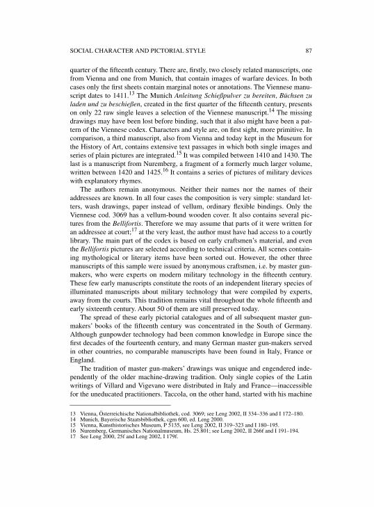
SOCIAL CHARACTER AND PICTORIAL STYLE 87
quarter of the fifteenth century. There are, firstly, two closely related manuscripts, onefrom Vienna and one from Munich, that contain images of warfare devices. In bothcases only the first sheets contain marginal notes or annotations. The Viennese manu-script dates to 1411.13 The Munich Anleitung Schießpulver zu bereiten, Büchsen zuladen und zu beschießen, created in the first quarter of the fifteenth century, presentson only 22 raw single leaves a selection of the Viennese manuscript.14 The missingdrawings may have been lost before binding, such that it also might have been a pat-tern of the Viennese codex. Characters and style are, on first sight, more primitive. Incomparison, a third manuscript, also from Vienna and today kept in the Museum forthe History of Art, contains extensive text passages in which both single images andseries of plain pictures are integrated.15 It was compiled between 1410 and 1430. Thelast is a manuscript from Nuremberg, a fragment of a formerly much larger volume,written between 1420 and 1425.16 It contains a series of pictures of military deviceswith explanatory rhymes.
The authors remain anonymous. Neither their names nor the names of theiraddressees are known. In all four cases the composition is very simple: standard let-ters, wash drawings, paper instead of vellum, ordinary flexible bindings. Only theViennese cod. 3069 has a vellum-bound wooden cover. It also contains several pic-tures from the Bellifortis. Therefore we may assume that parts of it were written foran addressee at court;17 at the very least, the author must have had access to a courtlylibrary. The main part of the codex is based on early craftsmen’s material, and eventhe Bellifortis pictures are selected according to technical criteria. All scenes contain-ing mythological or literary items have been sorted out. However, the other threemanuscripts of this sample were issued by anonymous craftsmen, i.e. by master gun-makers, who were experts on modern military technology in the fifteenth century.These few early manuscripts constitute the roots of an independent literary species ofilluminated manuscripts about military technology that were compiled by experts,away from the courts. This tradition remains vital throughout the whole fifteenth andearly sixteenth century. About 50 of them are still preserved today.
The spread of these early pictorial catalogues and of all subsequent master gun-makers’ books of the fifteenth century was concentrated in the South of Germany.Although gunpowder technology had been common knowledge in Europe since thefirst decades of the fourteenth century, and many German master gun-makers servedin other countries, no comparable manuscripts have been found in Italy, France orEngland.
The tradition of master gun-makers’ drawings was unique and engendered inde-pendently of the older machine-drawing tradition. Only single copies of the Latinwritings of Villard and Vigevano were distributed in Italy and France—inaccessiblefor the uneducated practitioners. Taccola, on the other hand, started with his machine
13 Vienna, Österreichische Nationalbibliothek, cod. 3069; see Leng 2002, II 334–336 and I 172–180.14 Munich, Bayerische Staatsbibliothek, cgm 600, ed. Leng 2000.15 Vienna, Kunsthistorisches Museum, P 5135, see Leng 2002, II 319–323 and I 180–195.16 Nuremberg, Germanisches Nationalmuseum, Hs. 25.801; see Leng 2002, II 266f and I 191–194.17 See Leng 2000, 25f and Leng 2002, I 179f.
88 RAINER LENG
drawings at least two decades after the first master gun-makers’ books. The only onefrom whom they possibly could have benefited was Konrad Kyeser, who wrote hisBellifortis six years before the first precisely dated master gun-makers’ book in theViennese cod. 3069 of 1411. But among the four eldest manuscripts, only one has adistant relationship to the Bellifortis as mentioned above. But Kyeser’s drawings didnot inspire the anonymous author: the first part of the manuscript is completely inde-pendent. All pictures derived from the Bellifortis are later additions to the second partof the codex, and none of them is listed in the opening table of contents on the firsttwo sheets.
Although the master gun-makers’ tradition was unique, these craftsmen did not,of course, “invent” drawing in general for their purposes. Some of the characteristicfeatures of the older courtly tradition, such as the use of different viewpoints or thedepiction of integral devices on one sheet, strikingly similar conventions or rules, canbe found in Villard’s sketch-book as well as in Vigevano’s and Kyeser’s illustratedmanuscripts on war.18 But considering the fact that no master gun-maker had everseen them (during their first attempts) it is plausible to assume that they used com-monly known pictorial techniques of the Middle Ages, which could be seen in anyillustrated book, in church glass and murals. These common elements of a pictoriallanguage, together with their very special everyday experiences with single roughdrawings for new constructions, constituted the foundation for the first pictorial col-lections by craftsmen in complete, unique and—as opposed to single sheet files—lasting manuscripts.
2. THE SOCIAL FUNCTION OF CRAFTSMEN’S MANUSCRIPTS
Immediately at the beginning of each manuscript we find drawings or texts with tech-nical content. None of the authors seems ever to have thought it necessary to addresshis readers or to explain the purpose of his writing. Thus, the social function of thesewritings has to be inferred by analyzing the social status of the author and by inter-preting the text and illustrations. We learn more about the master gun-makers bystudying their contracts.19 There is an increasing number of such working contractsfrom the 1370s onwards. Most of the master gun-makers had been working as black-smiths or metal-workers in medieval urban settlements. They left their traditionalworkplaces in order to specialize and thus to climb the social ladder. They oftenchanged employers, they were very well paid and relatively rare. Lords and citiesdepended on their detailed know-how of chemistry and weapon technology. Theirhigh mobility, their specific and valuable knowledge were the social basis of the firstmaster gun-makers’ codices.
For centuries, technical know-how had been passed on orally in a settled urbantradition. The solitary traveling gun-maker could not rely on such oral tradition. Hisprecious knowledge was always in danger of being lost in perilous military engage-
18 See the chapter by David McGee in this volume.19 See for the following Leng 1996.
SOCIAL CHARACTER AND PICTORIAL STYLE 89
ments. Only by setting down it on paper could master gun-makers ensure that theirknowledge be preserved enduringly for journeymen, apprentices and lords. Knowl-edge, as well as times, were changing: Military technology was developing quickly,instructions for the production of powder and additional substances became increas-ingly complicated, and their number was increasing. Master gun-makers were nolonger able to memorize those instructions. The Fireworkbook of 1420 had alreadydemanded that “Der Meister sol auch kennen schreiben und lesen.”20 Obviously therehad been frauds among the traveling masters. Those who were able to prove theirknowledge by producing written evidence were more likely to find employment.21
For these experts, the way out of the “sub-literate groups”22 into literacy was not toofar and, in any case, of big advantage.
At the beginning there may have been only single sheets, notes about gunpowderrecipes, single sketches of technical devices. These early documents of master gun-makers’ technology have been lost. Today we can trace them back only by studyingthe codices that were compiled later from this early material. Looking at the oldestcodices one can discover their relationship to those single-file collections.23
Apart from the task of passing on innovative knowledge, and from a partial pre-sentational function, these writings had one main social intention: the exchange oftechnical know-how. Communication among master gun-makers took place by wayof books: Master gun-makers mention their colleagues’ books, and they find them-selves mentioned, too: “… ze einer bedutnws eins andern puochs …”;24 “… diesensinn den suoch / in dem andern buoch …”25 Wherever single characteristic drawingscan be found in more than one manuscript, conclusions can be drawn about the rela-tionship between these codices and, thus, the exchange of drawings can be assumed.
Certainly the relationships among images of commonly known devices is hard toprove. But the Viennese manuscript cod. 3064, which can be dated to around 1440, isa nice example of parallel intertextual communication: in the inserted gunpowder rec-ipes, the writer names his colleagues who had invented them.26 It seems that theanonymous author was in close contact to his colleagues in the south of Germany,and they seem to have exchanged recipes quite frequently. The high mobility of mas-ter gun-makers and their regular meetings at the major sites of military conflict, forwhich large numbers of this trade were called together, favored such a literary com-munication. It is likely that on such occasions sketches were exchanged as well. This
20 Hassenstein 1941, 16: “... wann der stuck souil sind die darzu gehoerendt / die ein yetlicher guetterpüchsen meister künden soll / vnd die ein mayster on die geschrift in seinem sinne nit gedenckenkann ...” See also Hall (B.S.) 1979a, 47–58.
21 See Schmidtchen 1990 30, Leng 2002, I 105f.22 Hall (B.S.) 1979a, 48.23 See Leng 2002, I 151–154.24 Vienna, Österreichische Nationalbibliothek, cod. 3069, fol. Ir;—see Leng 2000, 25.25 Nuremberg, Germanisches Nationalmuseum, Hs. 25.801, f. 15r—see Leng 2002, I 193.26 Vienna, Österreichische Nationalbibliothek, cod. 3064, f. 9v “magistrum conradum,” f. 10r “ulreichs
mawrers puluer,” f. 10v “mayster johannes von Österreich,” f. 12v “also zugelt der marckgraf von rotelSalpeter” (who is also mentioned in Cologne, Archiv der Stadt Köln, W* 232 f. 84r and Frankfurt,Bibliothek des Instituts für Stadtgeschichte, Reichssachen Nachträge Nr. 741, 29), f. 16v “magistrumiohannem,” again f. 25v “magistrum iohannem de austria” and f. 26v “secundum iohannem.” For adescription of the manuscript see Leng 2002, II 331 and I 238.
90 RAINER LENG
explains why some characteristic drawings can be found in a number of pictorial cat-alogues all of which are not mere copies, but individual sketch-books.
The openness with which the master gun-makers apparently communicated theirknow-how and even inventions is remarkable.27 Of course, issues of secrecy arose onoccasion. The patrons of these experts were interested in spreading their knowledge.In the case of the master gun-maker’s death or absence, other servants or citizensshould be able to serve the ordnance, too. Therefore some contracts obliged the mas-ter gun-makers to teach few persons about shooting and the production of gunpow-der.28 But sometimes this produced undesirable competitors. In 1468 the master gun-maker of Lucerne claimed damages from the council, because some citizens, towhom he was obliged to convey his knowledge, had started producing gunpowder ontheir own. He complained about the reduction of his income.29 For such reasons mas-ter gun-makers could be interested in maintaining secrecy as regarded their monop-oly of know-how within their closer sphere. On the other hand, master gun-makerswere cleared for classified military information. No one knew better the attack ordefence potential of their patrons. Because of this, the employers themselves werevitally interested in forbidding the conveyance of knowledge, and included strictclauses in their employment contracts. Problems of secrecy occurred for economic ormilitary reasons, but they never seem to have prevented the transfer of technologicalknow-how in drawings among the master gun-makers. The group of skilled expertswas too small and too scattered—normally one master gun-maker per city!—for seri-ous competition. It seems they felt themselves to be colleagues obliged to each otherby their dangerous and exclusive profession more than as distrustful competitors.
The early production of illuminated technical manuscripts by craftsmen, whowere not writing for the courts but for themselves and for their colleagues, is autono-mous. It is not influenced by the presentational manuscripts such as those producedby Kyeser and Taccola. No master gun-maker would have understood the ambitious,literary Latin hexameters of the Bellifortis! Besides, the audience these craftsmenaddress is a different one. The drawings serve as a memory aid in the first place, butthey also pass on knowledge to journeymen, apprentices, and colleagues. For the firsttime we encounter texts and pictures that have been produced for communicationbetween skilled experts.
3. PICTORIAL STYLE: PRIMITIVE OR FUNCTIONAL?
The pictorial style, especially that of the early master gun-maker books, often hasbeen contemptuously called “crude” or “primitive.”30 Of course, the style of thesketches is rough. The simple feather drawings couldn’t compete with the magnifi-cent book illumination of Taccola or Kyeser. But as they were not meant for courtly
27 For the problem in general, see Long 2001, especially 117–122 about openness and secrets in writingson gunpowder artillery and machines, including some of the above-mentioned manuscripts.
28 For some examples see Leng 1996, 314f.29 See Hess 1920, 22.30 Gille 1964, 49f. and even Hall (B.S.) 1979b, 21f.
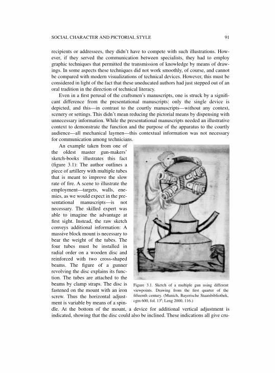
SOCIAL CHARACTER AND PICTORIAL STYLE 91
recipients or addressees, they didn’t have to compete with such illustrations. How-ever, if they served the communication between specialists, they had to employgraphic techniques that permitted the transmission of knowledge by means of draw-ings. In some aspects these techniques did not work smoothly, of course, and cannotbe compared with modern visualizations of technical devices. However, this must beconsidered in light of the fact that these uneducated authors had just stepped out of anoral tradition in the direction of technical literacy.
Even in a first perusal of the craftsmen’s manuscripts, one is struck by a signifi-cant difference from the presentational manuscripts: only the single device isdepicted, and this—in contrast to the courtly manuscripts—without any context,scenery or settings. This didn’t mean reducing the pictorial means by dispensing withunnecessary information. While the presentational manuscripts needed an illustrativecontext to demonstrate the function and the purpose of the apparatus to the courtlyaudience—all mechanical laymen—this contextual information was not necessaryfor communication among technicians.
An example taken from one ofthe oldest master gun-makers’sketch-books illustrates this fact(figure 3.1): The author outlines apiece of artillery with multiple tubesthat is meant to improve the slowrate of fire. A scene to illustrate theemployment—targets, walls, ene-mies, as we would expect in the pre-sentational manuscripts—is notnecessary. The skilled expert wasable to imagine the advantage atfirst sight. Instead, the raw sketchconveys additional information: Amassive block mount is necessary tobear the weight of the tubes. Thefour tubes must be installed inradial order on a wooden disc andreinforced with two cross-shapedbeams. The figure of a gunnerrevolving the disc explains its func-tion. The tubes are attached to thebeams by clamp straps. The disc isfastened on the mount with an ironscrew. Thus the horizontal adjust-ment is variable by means of a spin-dle. At the bottom of the mount, a device for additional vertical adjustment isindicated, showing that the disc could also be inclined. These indications all give cru-
Figure 3.1. Sketch of a multiple gun using differentviewpoints. Drawing from the first quarter of thefifteenth century. (Munich, Bayerische Staatsbibliothek,cgm 600, fol. 13r; Leng 2000, 116.)
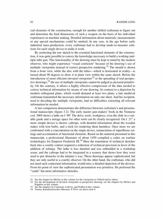
92 RAINER LENG
cial elements of the construction, enough for another skilled craftsman to figure outand determine the final dimensions of such a weapon on the basis of his individualexperiences in machine making. Detailed information about materials, measurementsor any special mechanisms could be omitted. In any case, in the age before earlyindustrial mass-production, every craftsman had to develop made-to-measure solu-tions for each single device to make it work.
By restricting the raw sketch to the essential functional elements of the construc-tion, it was quite possible to convey the knowledge necessary to build a working mul-tiple-tube gun. This functionality of the drawing must be kept in mind by the modernobserver, who might experience “visual confusion” because of the drawing’s use ofmultiple viewpoints instead of correct perspective rendering.31 The mould is shownfrom a front view, while the disc with the tubes—which is horizontal in reality—isturned about 90 degrees to show it in plain view within the same sketch. Before theintroduction of more efficient elevated viewpoints32 or the spreading of real perspec-tive drawings,33 the use of multiple viewpoints cannot be judged as pictorial primitiv-ity. On the contrary, it allows a highly effective compression of the data needed toconvey technical information by means of one drawing. In contrast to a depiction bymodern orthogonal plans, which would demand at least two plans, a late medievalcraftsman transmitted the necessary information on only one sheet. And his recipient,used to decoding the multiple viewpoints, had no difficulties extracting all relevantinformation he needed.
A last comparison demonstrates the difference between craftsmen’s and presenta-tional manuscripts (figure 3.2): The early master gun-makers’ book in the Viennesecod. 3069 shows a lathe on f. 90r. The drive, tools, workpiece, even the slide in a vari-able guide and a storage space for other tools can be clearly recognized. On f. 21v amore simple device is shown: caltrops, with detailed information about the woodenstakes with iron barbs, and a trick for rendering them harmless. Once more we areconfronted with a concentration on the single device, renunciation of superfluous set-tings and accentuation of functional elements. Based on the material presented in thismanuscript, a professional illustrator of about 1450 compiled a codex on warfaretechnologies for Emperor Frederick III.34 Here the translation of technical sketchesback into a courtly context required a reduction of technical precision in favor of theaddition of settings. The lathe is less detailed and was embedded in a workshopscene, and the caltrops had to be integrated in a scenery that shows how they wereused to put obstacles in the infantry’s way. These drawings appear sophisticated, butthey are only useful to a courtly observer. On the other hand, the craftsman, who didnot need such contextual information, would miss a detailed depiction of the devices.From his point of view the sophisticated presentation was primitive. He preferred the“crude” but more informative sketches.
31 See the chapter by McGee in this volume for the viewpoints in Villard and by others.32 For the development of elevated viewpoints or perspective drawing, see the chapters by McGee and
Popplow in this volume.33 See the chapters by Camerota, Lefèvre, and Peiffer in this volume.34 Vienna, Kunsthistorisches Museum, P 5014, see above note 8.
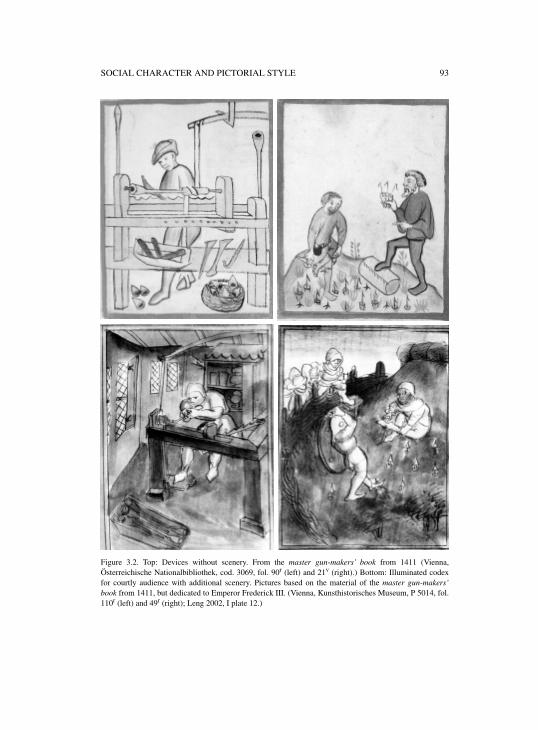
SOCIAL CHARACTER AND PICTORIAL STYLE 93
Figure 3.2. Top: Devices without scenery. From the master gun-makers’ book from 1411 (Vienna,Österreichische Nationalbibliothek, cod. 3069, fol. 90r (left) and 21v (right).) Bottom: Illuminated codexfor courtly audience with additional scenery. Pictures based on the material of the master gun-makers’book from 1411, but dedicated to Emperor Frederick III. (Vienna, Kunsthistorisches Museum, P 5014, fol.110r (left) and 49r (right); Leng 2002, I plate 12.)
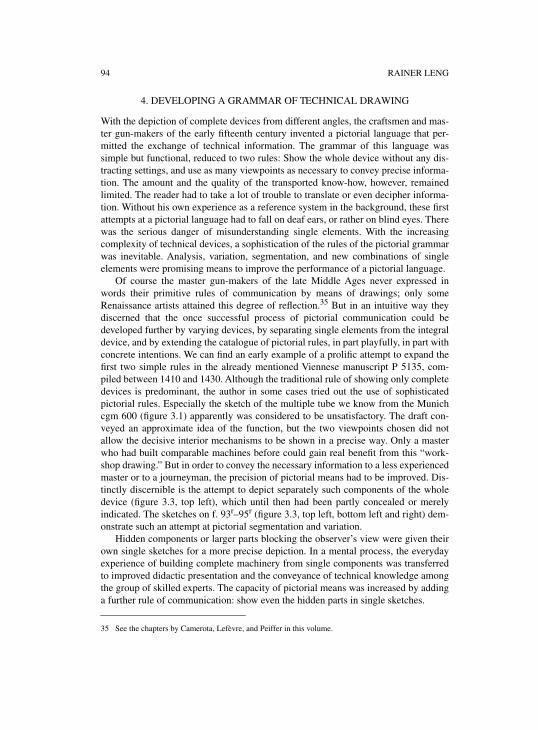
94 RAINER LENG
4. DEVELOPING A GRAMMAR OF TECHNICAL DRAWING
With the depiction of complete devices from different angles, the craftsmen and mas-ter gun-makers of the early fifteenth century invented a pictorial language that per-mitted the exchange of technical information. The grammar of this language wassimple but functional, reduced to two rules: Show the whole device without any dis-tracting settings, and use as many viewpoints as necessary to convey precise informa-tion. The amount and the quality of the transported know-how, however, remainedlimited. The reader had to take a lot of trouble to translate or even decipher informa-tion. Without his own experience as a reference system in the background, these firstattempts at a pictorial language had to fall on deaf ears, or rather on blind eyes. Therewas the serious danger of misunderstanding single elements. With the increasingcomplexity of technical devices, a sophistication of the rules of the pictorial grammarwas inevitable. Analysis, variation, segmentation, and new combinations of singleelements were promising means to improve the performance of a pictorial language.
Of course the master gun-makers of the late Middle Ages never expressed inwords their primitive rules of communication by means of drawings; only someRenaissance artists attained this degree of reflection.35 But in an intuitive way theydiscerned that the once successful process of pictorial communication could bedeveloped further by varying devices, by separating single elements from the integraldevice, and by extending the catalogue of pictorial rules, in part playfully, in part withconcrete intentions. We can find an early example of a prolific attempt to expand thefirst two simple rules in the already mentioned Viennese manuscript P 5135, com-piled between 1410 and 1430. Although the traditional rule of showing only completedevices is predominant, the author in some cases tried out the use of sophisticatedpictorial rules. Especially the sketch of the multiple tube we know from the Munichcgm 600 (figure 3.1) apparently was considered to be unsatisfactory. The draft con-veyed an approximate idea of the function, but the two viewpoints chosen did notallow the decisive interior mechanisms to be shown in a precise way. Only a masterwho had built comparable machines before could gain real benefit from this “work-shop drawing.” But in order to convey the necessary information to a less experiencedmaster or to a journeyman, the precision of pictorial means had to be improved. Dis-tinctly discernible is the attempt to depict separately such components of the wholedevice (figure 3.3, top left), which until then had been partly concealed or merelyindicated. The sketches on f. 93r–95r (figure 3.3, top left, bottom left and right) dem-onstrate such an attempt at pictorial segmentation and variation.
Hidden components or larger parts blocking the observer’s view were given theirown single sketches for a more precise depiction. In a mental process, the everydayexperience of building complete machinery from single components was transferredto improved didactic presentation and the conveyance of technical knowledge amongthe group of skilled experts. The capacity of pictorial means was increased by addinga further rule of communication: show even the hidden parts in single sketches.
35 See the chapters by Camerota, Lefèvre, and Peiffer in this volume.
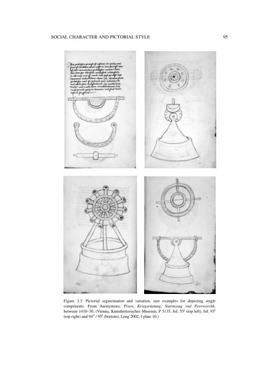
SOCIAL CHARACTER AND PICTORIAL STYLE 95
Figure 3.3. Pictorial segmentation and variation, rare examples for depicting singlecomponents. From Anonymous, Pixen, Kriegsrüstung, Sturmzeug vnd Fewrwerckh,between 1410–30. (Vienna, Kunsthistorisches Museum, P 5135, fol. 55r (top left), fol. 93r
(top right) and 94v / 95r (bottom); Leng 2002, I plate 10.)
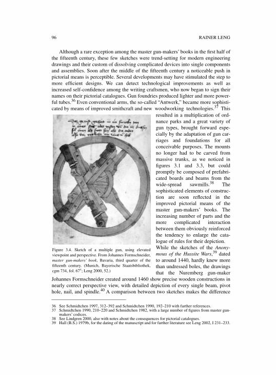
96 RAINER LENG
Although a rare exception among the master gun-makers’ books in the first half ofthe fifteenth century, these few sketches were trend-setting for modern engineeringdrawings and their custom of dissolving complicated devices into single componentsand assemblies. Soon after the middle of the fifteenth century a noticeable push inpictorial means is perceptible. Several developments may have stimulated the step tomore efficient designs. We can detect technological improvements as well asincreased self-confidence among the writing craftsmen, who now began to sign theirnames on their pictorial catalogues. Gun foundries produced lighter and more power-ful tubes.36 Even conventional arms, the so-called “Antwerk,” became more sophisti-cated by means of improved smithcraft and new woodworking technologies.37 This
resulted in a multiplication of ord-nance parks and a great variety ofgun types, brought forward espe-cially by the adaptation of gun car-riages and foundations for allconceivable purposes. The mountsno longer had to be carved frommassive trunks, as we noticed infigures 3.1 and 3.3, but couldpromptly be composed of prefabri-cated boards and beams from thewide-spread sawmills.38 Thesophisticated elements of construc-tion are soon reflected in theimproved pictorial means of themaster gun-makers’ books. Theincreasing number of parts and themore complicated interactionbetween them obviously reinforcedthe tendency to enlarge the cata-logue of rules for their depiction. While the sketches of the Anony-mous of the Hussite Wars,39 datedto around 1440, hardly knew morethan undressed boles, the drawingsthat the Nuremberg gun-maker
Johannes Formschneider created around 1460 show precise wooden constructions innearly correct perspective view, with detailed depiction of every single beam, pivothole, nail, and spindle.40 A comparison between two sketches makes the difference
36 See Schmidtchen 1997, 312–392 and Schmidtchen 1990, 192–210 with further references.37 Schmidtchen 1990, 210–220 and Schmidtchen 1982, with a large number of figures from master gun-
makers’ codices.38 See Lindgren 2000, also with notes about the consequences for pictorial catalogues.39 Hall (B.S.) 1979b, for the dating of the manuscript and for further literature see Leng 2002, I 231–233.
Figure 3.4. Sketch of a multiple gun, using elevatedviewpoint and perspective. From Johannes Formschneider,master gun-makers’ book, Bavaria, third quarter of thefifteenth century. (Munich, Bayerische Staatsbibliothek,cgm 734, fol. 67v; Leng 2000, 52.)
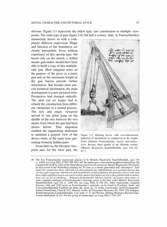
SOCIAL CHARACTER AND PICTORIAL STYLE 97
obvious. Figure 3.1 represents the oldest type: raw construction in multiple view-points. The same type of gun (figure 3.4), but half a century later in Formschneidersmanuscript, leaves us with a com-pletely different impression. Shapeand function of the foundation areclearly perceptible. Even withoutexperience of this special type, butbased only on the sketch, a skilledmaster gun-maker should have beenable to build a copy of this multiple-tube gun. Short marginal notes onthe purpose of the piece as a turretgun and on the maximum weight ofthe gun barrels provide furtherinformation. But besides more pre-cise technical information, the maindevelopment is a new pictorial style.Perspective had changed radically.The alert eye no longer had torebuild the construction from differ-ent viewpoints in a mental process.The new and single viewpointmoved to one point lying on themiddle of the axis between the twoangles from which the gun had beenshown before. That migrationenabled the engineering draftsmanto maintain a general view of thedevice while, at the same time, pre-senting formerly hidden parts.
From then on, the elevated view-point and, for the most part, the
40 The first Formschneider manuscript appears to be Munich, Bayerische Staatsbibliothek, cgm 734(c. 1460), see Leng 2002, II 206–209. On f. 60v the author gave some autobiographical information. Hecompiled the book by order of the Nuremberg council for his successor, Master Wagmeister. Previouslyhe had served in the Nuremberg armoury for 30 years as a master gun-maker and “adventurer”: Itemlieber her wagmeister diese stück hab ich eüch gemacht mer auff fürdrung ewer gnedigen herren danvon des geltz wegen dar vmb bitt ich eüch freuntlichen vnd fleissiglichen mit gantzem ernst Ir wolt euchdiese stück enpfolhen lassen sein vnd in rechter guoter huot halten als ich sy dan gehalten hab in meinerhuot wol xxx iar in nürnberg ... Johannes formschneider büchsen meister vnd guoter aben teürer. Amore complete catalogue of Formschneider’s drawings exists in the later codex Munich, BayerischeStaatsbibliothek, cgm 356 (c. 1480–90), see Leng 2002, II 198–201. Other manuscripts compiledbetween 1460 and 1500 based on Formschneider’s materials can be found in Frankfurt, Stadt- undUniversitätsbibliothek Frankfurt am Main, Ms. germ. qu. 14, Gotha, Universitäts- und Forschungsbib-liothek Erfurt/Gotha, Chart B 1032, Munich, Archiv des Deutschen Museums, Hs. 1949–258, Stuttgart,Württembergische Landesbibliothek, Cod. milit. 4° 31 and Weimar, Stiftung Weimarer Klassik/Anna-Amalia-Bibliothek, Q 342. For this group of manuscripts see Leng 2002, I 239–249.
Figure 3.5. Hoisting device with over-dimensionaldepiction of mechanisms in comparison to the weight.From Johannes Formschneider, master gun-makers’book, Bavaria, third quarter of the fifteenth century.(Munich, Bayerische Staatsbibliothek, cgm 734, fol.61v.)
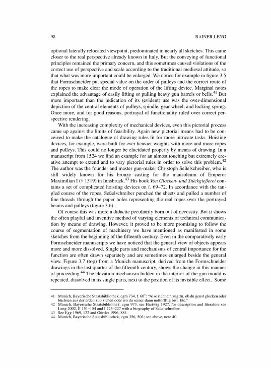
98 RAINER LENG
optional laterally relocated viewpoint, predominated in nearly all sketches. This camecloser to the real perspective already known in Italy. But the conveying of functionalprinciples remained the primary concern, and this sometimes caused violations of thecorrect use of perspective and scale according to the traditional medieval attitude, sothat what was more important could be enlarged. We notice for example in figure 3.5that Formschneider put special value on the order of pulleys and the correct route ofthe ropes to make clear the mode of operation of the lifting device. Marginal notesexplained the advantage of easily lifting or pulling heavy gun barrels or bells.41 Butmore important than the indication of its (evident) use was the over-dimensionaldepiction of the central elements of pulleys, spindle, gear wheel, and locking spring.Once more, and for good reasons, portrayal of functionality ruled over correct per-spective rendering.
With the increasing complexity of mechanical devices, even this pictorial processcame up against the limits of feasibility. Again new pictorial means had to be con-ceived to make the catalogue of drawing rules fit for more intricate tasks. Hoistingdevices, for example, were built for ever heavier weights with more and more ropesand pulleys. This could no longer be elucidated properly by means of drawing. In amanuscript from 1524 we find an example for an almost touching but extremely cre-ative attempt to extend and to vary pictorial rules in order to solve this problem.42
The author was the founder and master gun-maker Christoph Seßelschreiber, who isstill widely known for his bronze casting for the mausoleum of EmperorMaximilian I († 1519) in Innsbruck.43 His book Von Glocken- und Stückgießerei con-tains a set of complicated hoisting devices on f. 69–72. In accordance with the tan-gled course of the ropes, Seßelschreiber punched the sheets and pulled a number offine threads through the paper holes representing the real ropes over the portrayedbeams and pulleys (figure 3.6).
Of course this was more a didactic peculiarity born out of necessity. But it showsthe often playful and inventive method of varying elements of technical communica-tion by means of drawing. However, it proved to be more promising to follow thecourse of segmentation of machinery we have mentioned as manifested in somesketches from the beginning of the fifteenth century. Even in the comparatively earlyFormschneider manuscripts we have noticed that the general view of objects appearsmore and more dissolved. Single parts and mechanisms of central importance for thefunction are often drawn separately and are sometimes enlarged beside the generalview. Figure 3.7 (top) from a Munich manuscript, derived from the Formschneiderdrawings in the last quarter of the fifteenth century, shows the change in this mannerof proceeding.44 The elevation mechanism hidden in the interior of the gun mould isrepeated, dissolved in its single parts, next to the position of its invisible effect. Some
41 Munich, Bayerische Staatsbibliothek, cgm 734, f. 60v: “Also richt ein zug zu, ob du geust glocken oderbüchsen aus der erden zuo zichen oder wo du seiner dann nottürfftig bist. Etc.”
42 Munich, Bayerische Staatsbibliothek, cgm 973, see Hartwig 1927, for description and literature seeLeng 2002, II 151–154 and I 225–227 with a biography of Seßelschreiber.
43 See Egg 1969, 122 and Gürtler 1996, 88f.44 Munich, Bayerische Staatsbibliothek, cgm 356, 50f.; see above, note 40.
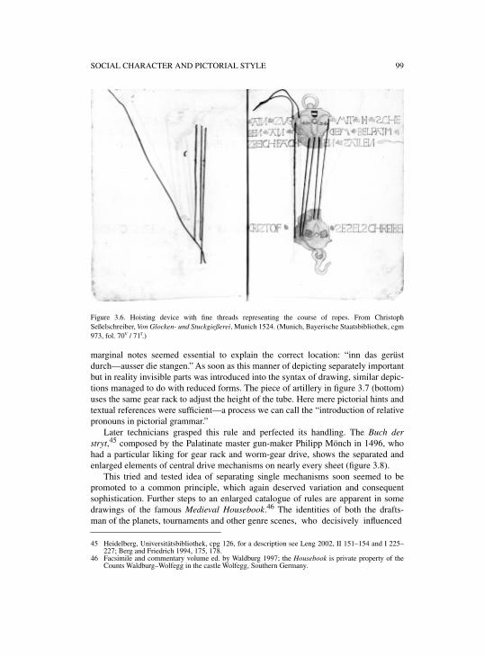
SOCIAL CHARACTER AND PICTORIAL STYLE 99
Figure 3.6. Hoisting device with fine threads representing the course of ropes. From ChristophSeßelschreiber, Von Glocken- und Stuckgießerei, Munich 1524. (Munich, Bayerische Staatsbibliothek, cgm973, fol. 70v / 71r.)
marginal notes seemed essential to explain the correct location: “inn das gerüstdurch—ausser die stangen.” As soon as this manner of depicting separately importantbut in reality invisible parts was introduced into the syntax of drawing, similar depic-tions managed to do with reduced forms. The piece of artillery in figure 3.7 (bottom)uses the same gear rack to adjust the height of the tube. Here mere pictorial hints andtextual references were sufficient—a process we can call the “introduction of relativepronouns in pictorial grammar.”
Later technicians grasped this rule and perfected its handling. The Buch derstryt,45 composed by the Palatinate master gun-maker Philipp Mönch in 1496, whohad a particular liking for gear rack and worm-gear drive, shows the separated andenlarged elements of central drive mechanisms on nearly every sheet (figure 3.8).
This tried and tested idea of separating single mechanisms soon seemed to bepromoted to a common principle, which again deserved variation and consequentsophistication. Further steps to an enlarged catalogue of rules are apparent in somedrawings of the famous Medieval Housebook.46 The identities of both the drafts-man of the planets, tournaments and other genre scenes, who decisively influenced
45 Heidelberg, Universitätsbibliothek, cpg 126, for a description see Leng 2002, II 151–154 and I 225–227; Berg and Friedrich 1994, 175, 178.
46 Facsimile and commentary volume ed. by Waldburg 1997; the Housebook is private property of theCounts Waldburg–Wolfegg in the castle Wolfegg, Southern Germany.
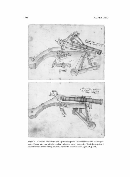
100 RAINER LENG
Figure 3.7. Guns and foundations with separately depicted elevation mechanisms and marginalnotes. From a later copy of Johannes Formschneider, master gun-makers’ book, Bavaria, fourthquarter of the fifteenth century. Munich, Bayerische Staatsbibliothek, cgm 356, p. 50f.)
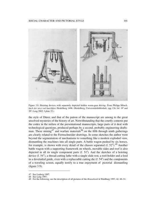
SOCIAL CHARACTER AND PICTORIAL STYLE 101
Figure 3.8. Hoisting devices with separately depicted hidden worm-gear driving. From Philipp Mönch,büch der stryt vnd buochßen, Heidelberg 1496. (Heidelberg, Universitätsbibliothek, cpg 126, fol. 19r and20r; Leng 2002, I plate 22.)
the style of Dürer, and that of the patron of the manuscript are among to the greatunsolved mysteries of the history of art. Notwithstanding that the courtly contexts putthe codex in the milieu of the presentational manuscripts, large parts of it deal withtechnological questions, produced perhaps by a second, probably engineering drafts-man. These mining47 and warfare materials48 on the fifth through ninth gatheringsare clearly related to the Formschneider drawings. In some sketches the author wentbeyond the segmentation of mechanisms to something like a modern exploded view,dismantling the machines into all single parts. A battle wagon pushed by six horses,for example, is shown with every detail of the chassis separated (f. 52v).49 Anotherbattle wagon with a supporting framework on wheels, movable sides and roof is alsodepicted in all its single component parts (f. 51r). And the sketches of a hoistingdevice (f. 54v), a thread-cutting lathe with a single slide rest, a tool-holder and a feedin a dovetailed guide, even with a replaceable cutting die (f. 54r) and the componentsof a traveling screen, equally testify to a true enjoyment of pictorial dismantling(figure 3.9).
47 See Ludwig 1997.48 See Leng 1997.49 For the following, see the description of all pictures of the Housebook in Waldburg 1997, 42, 48–51.
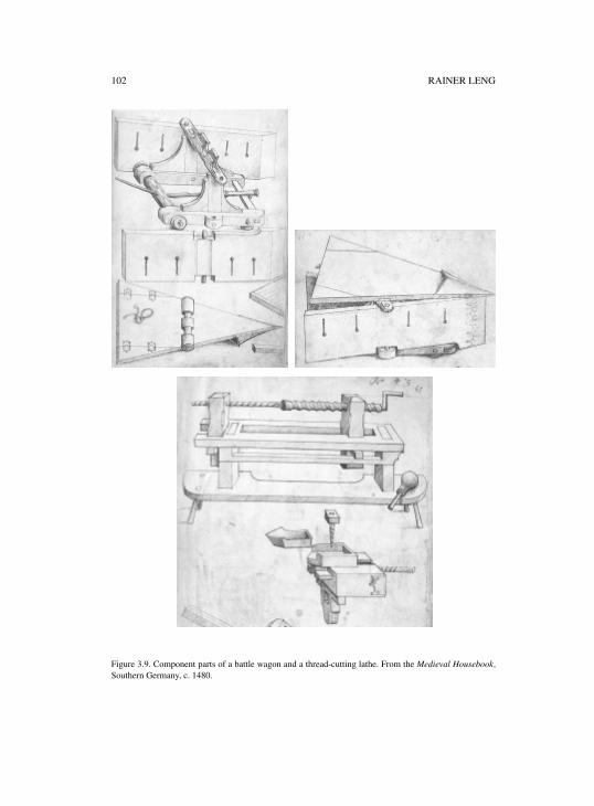
102 RAINER LENG
Figure 3.9. Component parts of a battle wagon and a thread-cutting lathe. From the Medieval Housebook,Southern Germany, c. 1480.
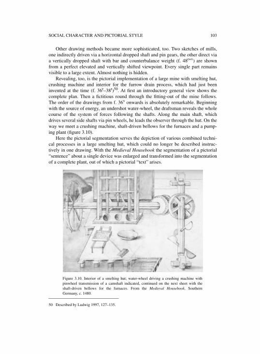
SOCIAL CHARACTER AND PICTORIAL STYLE 103
Other drawing methods became more sophisticated, too. Two sketches of mills,one indirectly driven via a horizontal dropped shaft and pin gears, the other direct viaa vertically dropped shaft with bar and counterbalance weight (f. 48r+v) are shownfrom a perfect elevated and vertically shifted viewpoint. Every single part remainsvisible to a large extent. Almost nothing is hidden.
Revealing, too, is the pictorial implementation of a large mine with smelting hut,crushing machine and interior for the furrow drain process, which had just beeninvented at the time (f. 36r–38r)50. At first an introductory general view shows thecomplete plan. Then a fictitious round through the fitting-out of the mine follows.The order of the drawings from f. 36v onwards is absolutely remarkable. Beginningwith the source of energy, an undershot water-wheel, the draftsman reveals the wholecourse of the system of forces following the shafts. Along the main shaft, whichdrives several side shafts via pin wheels, he leads the observer through the hut. On theway we meet a crushing machine, shaft-driven bellows for the furnaces and a pump-ing plant (figure 3.10).
Here the pictorial segmentation serves the depiction of various combined techni-cal processes in a large smelting hut, which could no longer be described instruc-tively in one drawing. With the Medieval Housebook the segmentation of a pictorial“sentence” about a single device was enlarged and transformed into the segmentationof a complete plant, out of which a pictorial “text” arises.
50 Described by Ludwig 1997, 127–135.
Figure 3.10. Interior of a smelting hut; water-wheel driving a crushing machine withpinwheel transmission of a camshaft indicated, continued on the next sheet with theshaft-driven bellows for the furnaces. From the Medieval Housebook, SouthernGermany, c. 1480.
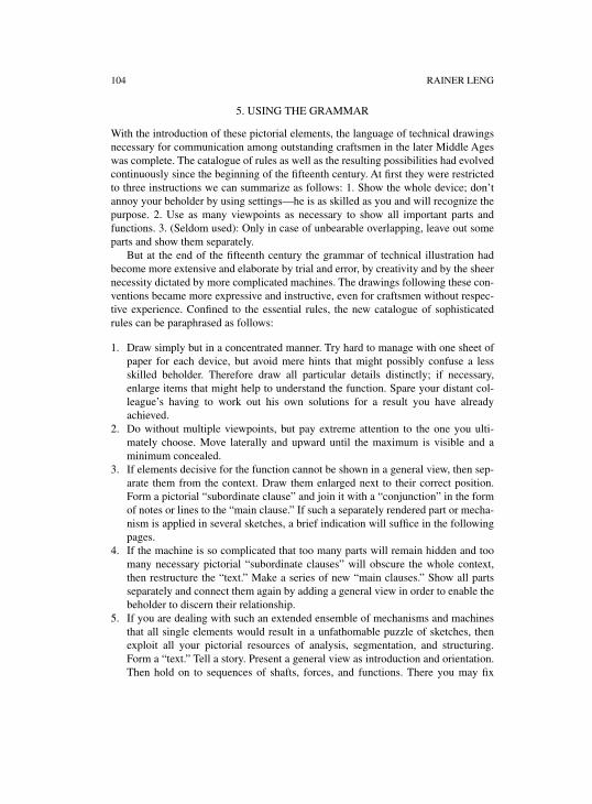
104 RAINER LENG
5. USING THE GRAMMAR
With the introduction of these pictorial elements, the language of technical drawingsnecessary for communication among outstanding craftsmen in the later Middle Ageswas complete. The catalogue of rules as well as the resulting possibilities had evolvedcontinuously since the beginning of the fifteenth century. At first they were restrictedto three instructions we can summarize as follows: 1. Show the whole device; don’tannoy your beholder by using settings—he is as skilled as you and will recognize thepurpose. 2. Use as many viewpoints as necessary to show all important parts andfunctions. 3. (Seldom used): Only in case of unbearable overlapping, leave out someparts and show them separately.
But at the end of the fifteenth century the grammar of technical illustration hadbecome more extensive and elaborate by trial and error, by creativity and by the sheernecessity dictated by more complicated machines. The drawings following these con-ventions became more expressive and instructive, even for craftsmen without respec-tive experience. Confined to the essential rules, the new catalogue of sophisticatedrules can be paraphrased as follows:
1. Draw simply but in a concentrated manner. Try hard to manage with one sheet ofpaper for each device, but avoid mere hints that might possibly confuse a lessskilled beholder. Therefore draw all particular details distinctly; if necessary,enlarge items that might help to understand the function. Spare your distant col-league’s having to work out his own solutions for a result you have alreadyachieved.
2. Do without multiple viewpoints, but pay extreme attention to the one you ulti-mately choose. Move laterally and upward until the maximum is visible and aminimum concealed.
3. If elements decisive for the function cannot be shown in a general view, then sep-arate them from the context. Draw them enlarged next to their correct position.Form a pictorial “subordinate clause” and join it with a “conjunction” in the formof notes or lines to the “main clause.” If such a separately rendered part or mecha-nism is applied in several sketches, a brief indication will suffice in the followingpages.
4. If the machine is so complicated that too many parts will remain hidden and toomany necessary pictorial “subordinate clauses” will obscure the whole context,then restructure the “text.” Make a series of new “main clauses.” Show all partsseparately and connect them again by adding a general view in order to enable thebeholder to discern their relationship.
5. If you are dealing with such an extended ensemble of mechanisms and machinesthat all single elements would result in a unfathomable puzzle of sketches, thenexploit all your pictorial resources of analysis, segmentation, and structuring.Form a “text.” Tell a story. Present a general view as introduction and orientation.Then hold on to sequences of shafts, forces, and functions. There you may fix
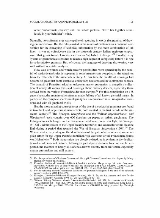
SOCIAL CHARACTER AND PICTORIAL STYLE 105
other “subordinate clauses” until the whole pictorial “text” fits together seam-lessly in your beholder’s mind.
Naturally, no craftsman ever was capable of recording in words the grammar of draw-ing outlined above. But the rules existed in the minds of craftsmen as a common con-vention for the conveying of technical information by the mere combination of inklines—it was no coincidence that in the sixteenth century Italian engineers empha-sized that geometrical elements serve as an “alphabet of design!”51 Finally, everysystem of grammatical signs has to reach a high degree of complexity before it is ripefor a descriptive grammar. But, of course, the language of drawing also worked verywell without scientific analysis.
How well it worked and which creative possibilities were opened up by the hand-ful of sophisticated rules is apparent in some manuscripts compiled at the transitionfrom the fifteenth to the sixteenth century. At this time the wealth of drawings hadbecome so great that some extensive collections had amassed in voluminous codices.The council of Frankfurt asked an unknown master gun-maker to compile a collec-tion of nearly all known texts and drawings about military devices, especially thosederived from the various Formschneider manuscripts.52 For this compilation on 178paper sheets, the anonymous craftsman made full use of all known pictorial means. Inparticular, the complete spectrum of gun types is represented in all imaginable varia-tions and with all graphical tricks.
But the most amazing consequences of the use of the pictorial grammar are foundin two thick and large-format manuscripts, both created in the first decade of the six-teenth century.53 The Erlangen Kriegsbuch and the Weimar Ingenieurkunst- undWunderbuch each contain over 600 sketches on paper, or rather, parchment. TheErlangen codex belonged to the Franconian nobleman Louis von Eyb, the Younger(† 1521), administrator of the Upper Palatine territories and counsellor of his PalatineEarl during a period that spanned the War of Bavarian Succession (1504).54 TheWeimar codex, depending on the identification of the patron’s coat of arms, was com-piled either for the Upper Palatine noblemen von Wolfstein or the Franconian countsvon Hohenlohe.55 Both manuscripts are closely related, as is evident in the duplica-tion of whole series of pictures. Although a partial presentational function can be sus-pected, the material of nearly all sketches derives directly from craftsmen, especiallymaster gun-makers and mill experts.
51 For the quotations of Girolamo Cataneo and his pupil Giacomo Lanteri, see the chapter by MarryHenninger-Voss in this volume.
52 Frankfurt, Stadt- und Universitätsbibliothek Frankfurt am Main, Ms. germ. qu. 14, on the front coversupralibros with the coat of arms of the city and inscription DIS BVCH GEHORT DEM RADE ZVFRANCFORT; for a description see Leng 2002, II 107–110 and I 267–269, plate 23 and 24.
53 For the tendency towards voluminous collections of pictorial catalogues at the end of the fifteenthcentury, see Leng 2002, I 269–279.
54 Erlangen, Universitätsbibliothek Erlangen-Nürnberg, Ms. B. 26; see for contents and also for thepatron’s biography, Keunecke 1992–93, and Leng 2002, II 97–100.
55 Weimar, Stiftung Weimarer Klassik / Anna-Amalia-Bibliothek, fol. 328; for contents see Kratzsch1979, Kratzsch 1981, Hall (B.S.) 1979b, 40f; on the discussion of the coat of arms, see Leng 2002, II292–296 and Metzger 2001, 253–264. An edition on CD-ROM is being prepared by ChristophWaldburg.
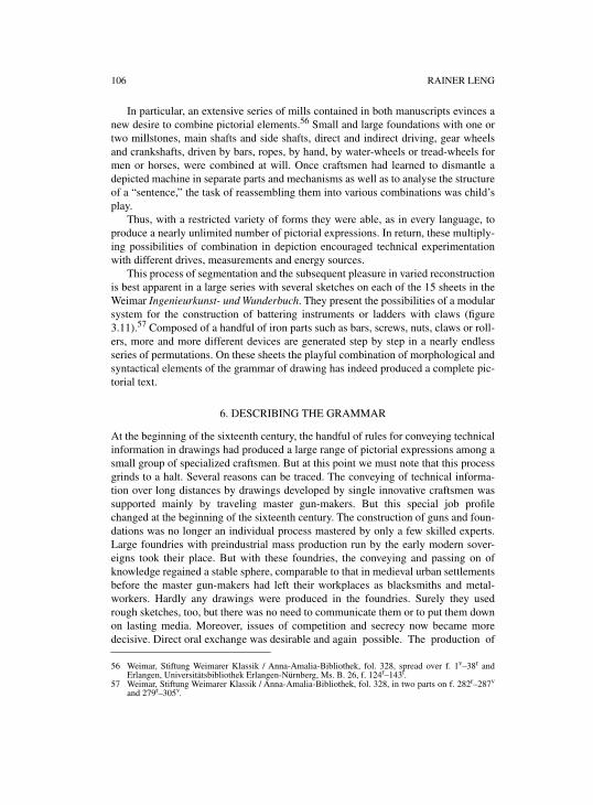
106 RAINER LENG
In particular, an extensive series of mills contained in both manuscripts evinces anew desire to combine pictorial elements.56 Small and large foundations with one ortwo millstones, main shafts and side shafts, direct and indirect driving, gear wheelsand crankshafts, driven by bars, ropes, by hand, by water-wheels or tread-wheels formen or horses, were combined at will. Once craftsmen had learned to dismantle adepicted machine in separate parts and mechanisms as well as to analyse the structureof a “sentence,” the task of reassembling them into various combinations was child’splay.
Thus, with a restricted variety of forms they were able, as in every language, toproduce a nearly unlimited number of pictorial expressions. In return, these multiply-ing possibilities of combination in depiction encouraged technical experimentationwith different drives, measurements and energy sources.
This process of segmentation and the subsequent pleasure in varied reconstructionis best apparent in a large series with several sketches on each of the 15 sheets in theWeimar Ingenieurkunst- und Wunderbuch. They present the possibilities of a modularsystem for the construction of battering instruments or ladders with claws (figure3.11).57 Composed of a handful of iron parts such as bars, screws, nuts, claws or roll-ers, more and more different devices are generated step by step in a nearly endlessseries of permutations. On these sheets the playful combination of morphological andsyntactical elements of the grammar of drawing has indeed produced a complete pic-torial text.
6. DESCRIBING THE GRAMMAR
At the beginning of the sixteenth century, the handful of rules for conveying technicalinformation in drawings had produced a large range of pictorial expressions among asmall group of specialized craftsmen. But at this point we must note that this processgrinds to a halt. Several reasons can be traced. The conveying of technical informa-tion over long distances by drawings developed by single innovative craftsmen wassupported mainly by traveling master gun-makers. But this special job profilechanged at the beginning of the sixteenth century. The construction of guns and foun-dations was no longer an individual process mastered by only a few skilled experts.Large foundries with preindustrial mass production run by the early modern sover-eigns took their place. But with these foundries, the conveying and passing on ofknowledge regained a stable sphere, comparable to that in medieval urban settlementsbefore the master gun-makers had left their workplaces as blacksmiths and metal-workers. Hardly any drawings were produced in the foundries. Surely they usedrough sketches, too, but there was no need to communicate them or to put them downon lasting media. Moreover, issues of competition and secrecy now became moredecisive. Direct oral exchange was desirable and again possible. The production of
56 Weimar, Stiftung Weimarer Klassik / Anna-Amalia-Bibliothek, fol. 328, spread over f. 1v–38r andErlangen, Universitätsbibliothek Erlangen-Nürnberg, Ms. B. 26, f. 124r–143r.
57 Weimar, Stiftung Weimarer Klassik / Anna-Amalia-Bibliothek, fol. 328, in two parts on f. 282r–287v
and 279r–305v.
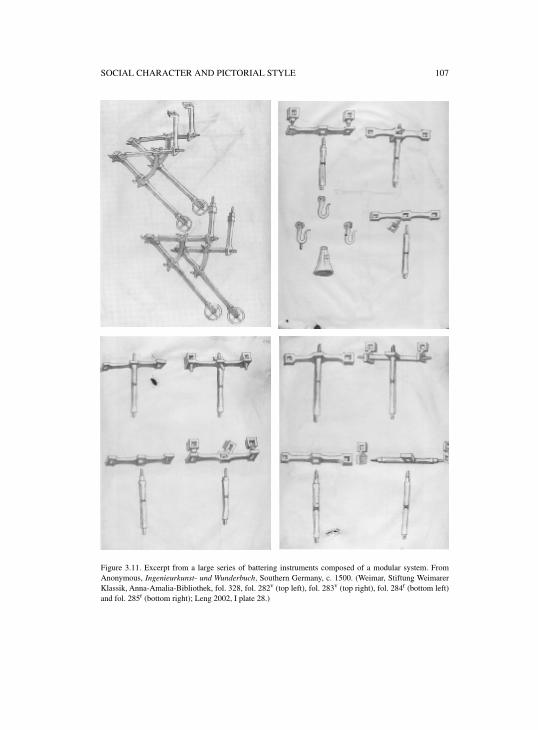
SOCIAL CHARACTER AND PICTORIAL STYLE 107
Figure 3.11. Excerpt from a large series of battering instruments composed of a modular system. FromAnonymous, Ingenieurkunst- und Wunderbuch, Southern Germany, c. 1500. (Weimar, Stiftung WeimarerKlassik, Anna-Amalia-Bibliothek, fol. 328, fol. 282v (top left), fol. 283v (top right), fol. 284r (bottom left)and fol. 285r (bottom right); Leng 2002, I plate 28.)
108 RAINER LENG
guns was separated from their professional use. The formerly independent status ofthe extensively skilled master gun-makers changed to that of a mere piece-laborer.
In the sixteenth century we still notice an extensive production of master gun-makers’ books. They no longer dealt with construction, but contain long-windedoperating instructions with pictures as mere decorative elements.58 Illustrations withseparated parts or assemblies became rare. They only appear, equipped with precisemeasurements, in the attempts of some masters in the armouries to standardize thevarious gun and foundation types.59
It can be mentioned in passing that the master gun-makers never attempted toanalyse their grammar of drawing theoretically. The only one who dared to present anilluminated full explanation for the construction of a gunner’s quadrant by means of aruler and pair of compasses, an exception admired by his colleagues, was the UpperPalatine master gun-maker Martin Merz († 1501).60 The inscription on his still extanttombstone in Amberg praises him not only as outstanding master gun-maker, but alsoas an excellent authority in mathematics and geometry.61 But his work was appar-ently ignored by his colleagues; no further copies are known.62
The majority of master gun-makers and craftsmen were satisfied with the resultsachieved—the development of a practical working language of pictorial communica-tion. The step into theory, the description of rules was up to the educated architectsand the artist engineers.63 After their inception in the Italian Renaissance, the circu-lating printed tracts by Dürer contributed to the spread of combined views and realperspective drawings even among technicians.64 Not until the end of the sixteenthcentury did the results of real perspective drawings become apparent both in thesketches of some technicians like Schickhardt65 and in the wide-spread printedRenaissance Books of Machines.66
In conclusion, one pictorial catalogue from the middle of the sixteenth centuryshall be pointed out as a remarkable instance for the quality technical drawings couldachieve against the background of conveying both experiences of practitioners and
58 For example the Buch von den probierten Künsten, compiled by the Cologne blacksmith and mastergun-maker Franz Helm in 1535, spread over Germany, especially in the new sovereigns’ libraries, inmore than 75 extant manuscripts, each with about 60 illustrations; ed. by Leng 2001; for an overviewof the numerous other master gun-maker books see Leng 2002, I 330–367.
59 For example, Dresden, Staats- und Universitätsbibliothek Dresden, C 363: hantbiechlin vnd ausszugvon meinen erfindungen, compiled 1570–80 by the Danzig master of the armouries Veitt Wolff vonSenftenberg, see Leng 2002, II 88–91.
60 Munich, Bayerische Staatsbibliothek, cgm 599, f. 66r–101v, see Leng 2002, II 88–91 and I 250–255.61 Amberg parish church, outside next to the entrance; see the figure of the tombstone along with the
inscription in Schmidtchen 1977, 182. 62 One more copy possibly can be identified in a manuscript mentioned by Schneider 1868 129f. in the
Library of the Princes of Liechtenstein in Vaduz, although today this manuscript is missing.63 For their contributions, see Long 1985, and several other chapters in this volume. For Brunelleschi or
Leon Battista Alberti see Fanelli 1980, 3–41; Gärtner 1998; on the development of perspective, recentlyBätschmann and Giaufreda 2002, 12–18; for Leonardo, see Parsons 1968, 15–93.
64 Dürer 1983 (1525) and 1969 (1525); for the extensive literature, see Mende 1971, 479–483. See alsothe chapters by Lefèvre and Peiffer in this volume.
65 See Popplow in this volume with further references.66 For example Besson 1569; Errard 1584; Ramelli 1588; Zonca 1985 (1607); Zeising 1607; Branca 1629;
Böckler 1661. For this genre, see Popplow 1998c, 103–124 and Popplow 1998a, 47, 54f.; Bacher 2000with several figures.
SOCIAL CHARACTER AND PICTORIAL STYLE 109
theoretical analysis. In the year 1558 the Nuremberg patrician Berthold Holzschuher(† 1582),67 finance broker,68 owner of several mines in Tyrol69 and passionate techni-cian and inventor, drew up his holographic will. He left his eldest son nothing but abundle of sketches with (as he thought) revolutionary driving methods for carriagesand mills.70 The book was to be kept secret and handed over by the executor to hisson after Berthold’s death. The heir was asked to call on cities, sovereigns, and kingswith these drawings and thus to get rich on his well-deserved user fees.
Here communication by means of drawings had to surmount temporal distances,and Holzschuher by necessity had to ensure that the sketches were perfectly compre-hensible without his help. Therefore he displayed the full range of pictorial meansavailable in the sixteenth century. Of course, the complicated gearing of the carriageswas influenced by the curious vehicles in Emperor Maximilian’s 1526 posthumouslyprinted Triumpf,71 and the style of technical drawing by Dürer’s architectural tracts.But the modernity of Holzschuher’s drawings is fascinating when compared withactual blueprints.
For all devices we find logical sequences of general views, segmentation intomechanisms and into every single component, precise depiction of gear wheels,axles, and transmissions, everything designed exactly with a ruler and a pair of com-passes. Dozens of erased help lines and hundreds of pricks on each sheet bear witnessto his detailed efforts. The last sheet of his will, a folded two-page perspective draw-ing of a large mill moving 16 millstones, constitutes the highlight of the book (figure3.12). Beforehand every single component was introduced. Additionally, three hori-zontal sections on the ground level, the shaft system level, and the top view madeclear the interaction of framework, components, and the system of forces.
The most amazing fact is that all drawings are completely true to scale. Next toeach sketch explanatory notes point out whether a quarter, a half or a complete inchon the paper corresponds to one Roman foot (c. 29,8 cm). Sometimes extra scales areadded at the margins of the plans. Character legends join up each component to writ-ten explanations. Not only the purpose of the devices, their construction and combi-nation is exhaustively explained step by step, but also the method of depiction. Thelast will of Berthold Holzschuher therefore can be considered as one of the first mod-ern blueprints containing both a theory of technical drawing and an expressive exam-ple of their application.
Holzschuher’s sketches remained a never-realized and soon-forgotten curiosity.None of the devices would have worked because he had misjudged gear ratio step-upand frictional losses. But their creation once more shows the social significance of
67 For his biography, see Koch 1972, 579f.68 For his financial activities, amongst them a revolutionary dowry insurance, see Ehrenberg 1890 and
Krieg 1916.69 See Kunnert 1965, 246–249.70 Nuremberg, Germanisches Nationalmuseum, Hs. 28.893; for some short notes and a few figures see
Neuhaus 1940 and Rauck 1964; for a description of the manuscript see Leng 2002, II 269–271. Theauthor is preparing an chapter to be printed in the “Mitteilungen des Vereins für die Geschichte der StadtNürnberg.”
71 Facsimile ed. by Appelbaum 1964, on the carriages, see 90–99.
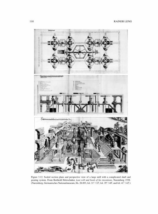
110 RAINER LENG
Figure 3.12. Scaled section plans and perspective view of a large mill with a complicated shaft andgearing system. From Berthold Holzschuher, Last will and book of his inventions, Nuremberg 1558.(Nuremberg, Germanisches Nationalmuseum, Hs. 28.893, fol. 31v / 32r, fol. 39v / 40r, and fol. 41v / 42r.)
SOCIAL CHARACTER AND PICTORIAL STYLE 111
craftsmen’s manuscripts. The more skilled experts had to convey increasingly com-plicated technical know-how over spatial and temporal distances, the more sophisti-cated and efficient became the basis of communication, with a catalogue of drawingrules serving as a pictorial grammar. Their tentative development and practical testingfrom the beginning of the fifteenth century onwards led to the creation of some con-ventions in the following century, which are obeyed in technical drawing to this veryday. Thus some fundamental blueprint techniques may be rooted not only in educatedearly modern engineering, but also in later medieval craftsmen’s practice.


PART IIISEEING AND KNOWING

INTRODUCTION TO PART III
The topic of this section is the intricate relationship between technical drawings andknowledge—knowledge those drawings presuppose and/or allude to, invoke, transmitexplicitly or implicitly, and/or knowledge, finally, that they help to gain. Besides “lit-eracy” with regard to the different pictorial languages employed, the reading of tech-nical drawings presupposes a spectrum of knowledge of different provenance—technological knowledge regarding both the construction and the working of thedepicted device, expertise as regards the practical context of its intended employ-ment, mechanical assumptions or other convictions of how natural things work, andsometimes even mathematical and geometrical knowledge. Accordingly, what thesedrawings actually convey depends to no little extent on the beholder’s familiaritywith the represented object and its whereabouts. They tell different things to expertsand nonexperts, to the artisans who construct the device, to other experts who employit professionally, and to lay people who are interested in it for any reason.
Technical drawings thus constitute a sort of focus where different kinds of knowl-edge come together and intersect. As such a focus, they radiate, in turn, into differentdomains of knowledge whose relations to the realm of engineering thus became rec-ognizable. They are therefore mirrors of the intellectual world of early modern engi-neering if one succeeds in reconstructing the ways in which knowledge wasconnected with them.
The fact that technical drawings presuppose so much knowledge of all sorts is ofcourse due in part to the limited representational capacity given by their restriction totwo dimensions, and to the special semiotic shortcomings of each of the different pic-torial languages. Technical drawings thus may appear to imply rather than displayand convey knowledge. However, such a view not only would be at odds with thegeneral fact that these drawings were an indispensable means of communicatingideas, proposals, solutions, agreements, and the like. It also would miss a dimensionof early modern engineering drawings that is of particular significance in this context.Rather than depending mainly on presupposed knowledge, these drawings contrib-uted essentially to the transformation of implicit, tacit knowledge of the crafts intoexplicit knowledge. They proved to be a chief means of rendering implicit knowledgeexplicit.
The chapter by Pamela Long studies the ways in which Francesco di GiorgioMartini and Leonardo da Vinci, two outstanding masters of engineering drawing, pro-moted the articulation of experiences and knowledge of engineering by means ofboth drawings and texts. Struggling for clarity, both were innovative in coining newterminology as well as in introducing new pictorial formulas, thereby creating anintertwined whole of pictorial and verbal elements that represented practitioners’knowledge with combined forces.
The relationship between image and text in illustrated manuscripts and books onengineering issues, which deserves much more attention than could be paid in thisvolume, is of particular interest with respect to the advantages and shortcomings ofthe two media as regards the articulation of technological knowledge. Both Giorgio
116 INTRODUCTION TO PART III
Martini’s treatises and Leonardo’s notebooks demonstrate impressively that such anarticulation and explication cannot be achieved by either of the two media alone. Or,to put it more precisely, they show that the capabilities to spell out technologicalknowledge each of them possesses can only be exploited fully when each elucidatesthe other. In this field of knowledge, images explain words no less than wordsimages. Furthermore, the combination of verbal and pictorial means of representationopened up new possibilities for connecting the knowledge of this realm of practicewith a variety of branches of learned culture. Pamela Long’s chapter shows that thisopportunity was immediately realized and seized by Giorgio Martini and Leonardo,albeit in quite different manners.
The notebooks of Leonardo also testify to a further aspect of the relationshipbetween drawings and knowledge, namely to the employment of drawings for theobtainment of insights—insights of a more theoretical nature as well as more practi-cal ones. When employed in this way as a means of thinking, technical drawings andknowledge exhibit an interplay that is challenging to both the historical actors and thehistorian who tries to determine which knowledge was tacitly presupposed, whichactually represented, and which gained by drawings used for this purpose.
This interplay is the topic of the chapter by Mary Henninger-Voss, who discussesthe employment of plans by civilian and military experts in the service of Venice forconsulting and deciding on crucial questions of fortification at the turn of the fifteenthcentury. When applied for these purposes, a fortification plan resembles an iceberg.For what can actually be seen on the plan is only the visible peak, whereas the bulk ofinformation it contains for an expert is as invisible to a nonexpert as the main body ofan iceberg under water. Moreover, since specialists of different expertise interact insuch decision-making, military architects and military commanders in this case, thewhole range of knowledge presupposed by, connected with, and derivable from a for-tification plan is not possessed by any of the specialists, but only by an ideal team ofexperts representing the state of the arts involved. What is obvious in this case holdsfor the relationship between technical drawings and knowledge in general: it is medi-ated by the social relations among the actors involved in advanced technologicalprojects.

4
PICTURING THE MACHINE:FRANCESCO DI GIORGIO AND LEONARDO DA VINCI
IN THE 1490s
PAMELA O. LONG
In memoriam Carolyn Kolb (1940–1994)
At the start of his notebook on machine elements and mechanics, Madrid Codex I,which he created in the 1490s, Leonardo da Vinci, at the time a client of LudovicoSforza of Milan, suggests that his treatise would provide a respite from fruitlesslabors, namely the attempt to discover perpetual motion.1 “I have found among theother superfluous and impossible delusions of man,” he writes, “the search for contin-uous motion, called by some perpetual wheel.” He continues that for many centuries,almost all those who worked on hydraulic and other kinds of machines devoted “longsearch and experimentation with great expense” to this problem. “And always in theend, it happened to them as to the alchemists, that through a small part the whole islost.” Leonardo offers to give such investigators “as much respite in such a search asthis my small work lasts.” An additional advantage is that readers will be able to ful-fill their promises to others so that they will “not have to always be in flight as a resultof the impossible things that were promised to princes and rulers of the people.” Herecalls many who went to Venice “with great expectation of gain, and to make millsin dead water. But after much expense and effort, unable to move the machine, theywere obliged to move themselves away with great haste from such a place.”2
Leonardo may well be referring to attempts by his older contemporary, the archi-tect/engineer Francesco di Giorgio, to construct water-powered mills in “dead water”(aqua morte) by a system powered by continuously circulating water. Yet evidencefrom several notebooks attests that Leonardo himself on several occasions investi-
1 I would like to thank Wolfgang Lefèvre for organizing the workshop at the Max Planck Institute for theHistory of Science that prompted me to write this chapter. Versions of the chapter were presented at theJoint Colloquium, Princeton University Program in History of Science and University of PennsylvaniaDepartment of History and Sociology of Science; and at the Department of History and Philosophy ofScience, Indiana University at Bloomington. I thank the participants of these colloquia as well as themembers of the Max Planck workshop for their extremely helpful comments which helped me to revisethe chapter. I also thank Guido Giglioni for detailed discussions of Francesco di Giorgio’s Italian,Steven Walton for discussions concerning Leonardo’s cranks, and Bob Korn for assistance with modelsand “photoshop” enhancement of images.
2 Leonardo 1974, I f. 0r, and IV 2, “Io ho trovato infra l’altre superchie e impossibile credulità degli ominila cierca del moto continuo, la quale per alcuno è decta rota perpetua”; “co’llunga cierca esspe[ri]mentatione e grande spesa”; “E ssenpre nel fine intervenne a lloro come alli archimisti, che peruna picola parte si perdea il tutto”; “tanto di quiete in tale cierca, quanto durerà questa mia picolaopera”; “none aranno senpre a stare in fughe, per le cose impossibile promesse ai principi e regitori dipopoli.”; “con grande speranze di provisioni, e fare mulina in acqua morta Che non potendo dopo moltaspesa movere tal machina, eran costretti a movere con gran fu[ri]a sè medesimi di tale aer.”
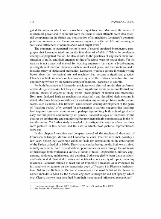
118 PAMELA O. LONG
gated the ways in which such a machine might function. Moreover, the issues ofmechanical power and friction that were the focus of such attempts were also essen-tial components in the design and construction of all machines. Leonardo’s commentpoints to common areas of concern among engineers in the late fifteenth century, aswell as to differences of opinion about what might work.3
The comment on perpetual motion is one of several unrelated introductory para-graphs that Leonardo tried out on the first sheet of Madrid I. While he condemnsattempts at perpetual motion, he also alludes to the practices of engineers, their con-struction of mills, and their attempts to find efficacious ways to power them. Yet histreatise is not a practical manual for working engineers, but rather a broad-ranginginvestigation of machine elements, such as cranks and gears, and their motions, and itincludes study of statics and mechanics. Leonardo lived in a culture in which writingbooks about the mechanical arts and machines had become a significant practice.Clearly a notable influence on his own writing were the treatises on architecture andengineering written by the Sienese architect/engineer, Francesco di Giorgio.
For both Francesco and Leonardo, machines were physical entities that performedcertain designated tasks, but they also were significant within larger intellectual andcultural arenas as objects of study within investigations of motion and mechanics.Both men depicted intricate mechanisms pictorially and described their motions indetail. Machines became modalities for understanding certain problems in the naturalworld, such as motion. The fifteenth- and sixteenth-century development of the genreof “machine books,” often created for presentation to patrons, suggests that machineshad acquired symbolic value as well, perhaps representing both technological effi-cacy and the power and authority of princes. Pictorial images of machines withincodices on architecture and engineering became increasingly commonplace in the fif-teenth century. Yet further study is needed to investigate the ways in which machineswere pictured in this period, and the uses to which those pictorial representationswere put.
In this chapter I examine and compare several of the mechanical drawings ofFrancesco di Giorgio Martini and Leonardo da Vinci. The two men met, possibly afew years before they were both called to Pavia for consultation on the constructionof the Pavian cathedral in 1490s. They shared similar backgrounds. Both were trainedinitially as painters, both expanded their opportunities for work through the astute useof patronage, both worked at a variety of kinds of tasks—engineering, military engi-neering, sculpture, architecture, and painting. Both struggled to learn Latin as adults,and both created illustrated treatises and notebooks on a variety of topics, includingmachines. Leonardo studied at least one of Francesco’s treatises as is evidenced byhis hand-written glosses on the manuscript copy of Trattato I in Florence (Ashburn-ham 361 in the Biblioteca Mediceo-Laurenziana). Leonardo’s list of the books heowned includes a book by the Sienese engineer, although he did not specify whichone. Clearly the two men benefited from their meeting and influenced one another.4
3 Francesco di Giorgio Martini 1967, I 148 and f. 35v (tav. 66); and see Reti 1969.4 See Pedretti 1985; and Marani 1991.
FRANCESCO DI GIORGIO AND LEONARDO 119
Francesco and Leonardo both concerned themselves with real machines in thecontext of their engineering and architectural work carried out for their patrons. Inaddition, in their writings and illustrations, they connected machines to learnedknowledge traditions in obvious and not so obvious ways. Nevertheless, the ways inwhich these two engineer/authors approached machines pictorially, and the ways inwhich they attempted to join their practical knowledge of machines to traditions oflearning were quite diverse. A comparison of their dissimilar approaches allows abetter understanding of how mechanical knowledge in the practical sense came to beconnected to learned traditions in the late fifteenth century. Both men made theseconnections by means of illustrated writings, or what in some cases might be bettercalled collections of images inscribed with small amounts of text. As a shorthand wayof codifying their differences, I suggest that Francesco di Giorgio created a humanistbook in which his interest in engineering finds a place alongside his architecturalinterests, whereas Leonardo da Vinci created a treatise more directly connected to thescholastic traditions of statics and kinematics.
Each in his own way was carrying on what was a well-established and rich tradi-tion of visualizing machines by the late fifteenth century. There were a few ancientbooks that contained illustrations of machines—most notably the De architectura bythe Roman architect Vitruvius, the original drawings of which had been lost, andGreek manuals on siege machines, the so-called poliorcetic treatises, containingbeautiful, hand-colored illustrations of siege ladders, rams, and other military equip-ment.5 Occasionally machinery is depicted in notebooks and treatises in the medievalcenturies, such as a sawmill on one of the sheets created by Villard de Honnecourt inthe thirteenth century, and plows and mills depicted in miniature in books of days andin almanacs. Nevertheless, there is an unmistakable expansion of drawings depictingmachines and instruments from the late fourteenth century. Examples include thetreatise and drawings on the astrarium by Giovanni da Dondi; the treatise on militaryweapons and war machines by Guido da Vigevano, the machines depicted in ConradKyeser’s Bellifortis; the numerous drawings of guns, gun carriages, and othermachines in fifteenth-century German manuscripts; machine drawings in a manu-script treatise Liber instrumentorum bellicorum by Giovanni Fontana; the well-known notebooks and treatises of the Sienese notary, Mariano Taccola, which wereknown to both Francesco di Giorgio and Leonardo; and the military machinesdepicted in Roberto Valturio’s De re militari libri XII, by far the most popular mili-tary book of the fifteenth century, copied many times and printed in 1472.6
Writings about the mechanical arts—painting, sculpture, architecture, fortifica-tion, artillery, pottery, mining, and metallurgy, including machines and visual repre-
5 For a spectacular eleventh/twelfth-century copy of the poliorcetic writings with numerous drawings ofmilitary apparatus and machines, see Biblioteca Apostolica Vaticana, Cod. Vat. gr. 1164, esp. ff. 88v–135r. And see Schneider 1912, esp. 4–6 and plates; Galluzzi 1996a, 22; Rowland 1998, 35–37; andLefèvre 2002, 112f.
6 For an introduction to the scholarly literature and editions of the treatises, see esp. Aiken 1994; Alertz2001; Barnes 1982; Hall 1978; Hall 1976a; Leng 2002; Long 2001, 102–142; and Popplow 1998a. Seealso the chapter by David McGee in the present volume. For a lucid essay on attitudes toward themechanical arts from antiquity to the Renaissance, see Summers 1987, 235–265.
120 PAMELA O. LONG
sentations of machines—proliferated in the fifteenth and sixteenth centuries. Thecomplex reasons for this expansion of authorship in the mechanical arts include whathistorians of technology have called technological enthusiasm, a delight in the tech-nology of machines in itself, regardless of economic or practical implications.7
Machines were utilized to solve technological problems and to consider more theo-retical issues involving statics and kinematics. As they became the focus of pictorialand textual authorship, they became incorporated into literate discourse in a varietyof ways. Machines accompanied by visual images of machines and machine parts,including multiple variations of machine elements such as gearing, and of entiremachines such as mills and guns, became a significant focus of authorship. Whilesuch books had distinct relationships with the actual practice of making and operat-ing machinery and inventing new configurations of actual machinery, it is also truethat they entailed a kind of practice separate from material fabrication and operation.Machine drawings do not necessarily provide an undistorted lens into material prac-tices. The relationships of images and textual discussions to material practice is amatter for investigation rather than a given. Moreover, as will be seen in the discus-sion below, the relationship of “machine books” to the cultures of learning and ofpractice were never uniform, but rather were complex and diverse from one text andauthor to another.
1. FRANCESCO DI GORGIO: ENGINEER AND ASPIRING HUMANIST
Francesco di Giorgio (1439–1501) was the son of a poulterer who had left this occu-pation in the countryside to work for the commune of Siena. Francesco thereby grewup in Siena at the time when the notary Mariano Taccola was still alive; he may wellhave known the older man and was well acquainted with the latter’s engineering note-books and treatises. Taccola had completed De ingeneis in the 1420s and De machi-nis in the 1430s and 1440s. Both were filled with drawings of machines andinstruments and often included short commentaries. Taccola, who called himself the“Sienese Archimedes,” influenced Francesco in the latter’s production of notebooksand treatises. For example, Francesco’s earliest notebook, the so-called codicetto inthe Vatican Library, contains a substantial number of copies from the notebooks ofTaccola. Francesco combined his interest in machines and engineering with architec-ture, including the design and construction of buildings and the study of the Romanarchitect Vitruvius’s De architectura. Francesco, who initially worked as a painterand sculptor, went on to become one of the best known architects and engineers ofthe late quattrocento. He worked in Siena, in Urbino for Federico da Montefeltro, inNaples for king Alfonso II, and elsewhere.8
Close investigation of Francesco’s notebooks and writings have made clear hisstruggles to learn Latin, an effort that he seems to have made primarily to understand
7 For technical authorship, see Long 2001, and for technological enthusiasm, Post 2001, esp. xviii–xxand 285–308.
8 For Francesco, see esp. Betts 1977; Fiore and Tafuri, eds. 1993; Scaglia 1992; and Toldano 1987. ForTaccola, see Taccola 1971; Taccola 1972; Taccola 1984a; and Taccola 1984b.
FRANCESCO DI GIORGIO AND LEONARDO 121
the De architectura. He eventually was able to produce an Italian translation of thetext in the 1480s. An early attempt at writing an architectural treatise and translatingVitruvius can be seen in a manuscript known as the Zichy Codex in Budapest, which,Carolyn Kolb cogently argued, includes a copy of an early treatise by Francesco.Francesco’s better known writings include two major treatises on architecture, mili-tary engineering, and machines. He wrote the first, known as Trattato I, a later ver-sion of Zichy, during his first major sojourn to Urbino from 1477 to 1480 as a resultof the interest (and perhaps urging) of his patron, Federico da Montefeltro. He wrotethe second treatise, known as Trattato II, later, perhaps in the years 1487 to 1489, oras has recently been suggested, even later after his return from Naples to his nativeSiena in 1496. The precise chronology of Francesco’s notebooks and treatises is acomplex issue that is the focus of ongoing investigation and scholarly disagreement.Yet all agree that his two major treatises are quite different from each other and thatone is earlier than the other. A comparison of the two works as they concernmachines underscores these differences. Trattato I is the detailed treatment thatreflects the concerns of a practising engineer. Trattato II sets out the topics accordingto more general principles, and follows some of the practices of humanist author-ship.9
Trattato I exists in two copies created by professional scribes. The first, L, createdaround 1480 to 1482, is in the Biblioteca Mediceo-Laurenziana (Codice Ashburnham361) in Florence, and the second, T, containing some of Francesco’s amendments andadditions, created around 1482–1486, is in the Biblioteca Reale (Codice Saluzziano148) in Turin. The two manuscripts form the basis for the twentieth century edition,edited and transcribed by Corrado Maltese and Livia Maltese Degrassi and publishedin 1967. As Massimo Mussini suggests, the specificity of the technical details of thedrawings of Trattato I make it certain that Francesco himself was closely involved intheir execution. The most complete version (T) is divided into eighteen sections, ortopics, which are not labelled in the original manuscript. Many of the sections repre-sent certain categories of problems or projects confronted by engineers. There is asection on forts, but also one on the bridges of forts and on other types of defense.The chapter on theatres is followed by a separate section on columns. Other sectionsinclude practical measurement, lifting machines and mills; ways of conducting water,metals (not present in L), military arts and machines, convents, instruments, bells,towers, and gardens. The abundant drawings are found within the columns of text andin the margins of the sheets and were probably executed by Francesco himself, as wasestablished by Mario Salmi in 1947 by comparison with other of Francesco’s knowndrawings. Although the exact circumstances of the origins of the two manuscriptscannot be reconstructed fully, Mussini’s suggestion that they may have been createdin Francesco’s workshop in Siena is an attractive one.10
9 Francesco di Giorgio Martini 1967. For the Zichy codex, see Kolb 1988; and see Mussini 1991a, 82–88, 108–109, 121–124, note 75–79; and Mussini 1991b. For Francesco’s translation of Vitruvius, seeFiori 1985; and Scaglia 1985.
122 PAMELA O. LONG
Trattato I contains several sections that focus specifically on machines—militarymachines, cranes and lifting devices, and mills of various kinds. In the following Ilook at one of these sections, called by the editors, “levers of wheels and mills.” Thissection takes up seven folios or fourteen sheets. The text is written in carefullyblocked-out columns, two columns per sheet, by a professional scribe. Interspersedwith the columns are box-shaped drawings of mills with their wheels and gears care-fully depicted. There are a total of 58 such drawings which, taken as a whole, explainmany variations of mills. There are water powered mills including those with hori-zontal, overshot, and undershot wheels, each in a variety of configurations. There aredry mills powered by animals, mills turned by cranks, and windmills. Taken as awhole, the images reveal two characteristics. First, most of the mills are set into neat,near-square boxes that are aligned with the columns of text. The drawings are madeto conform to scribal guidelines, namely the width of the columns of text, squareblocks of text and block-like images of mills reflecting one another. Second, it is clearthat Francesco is interested in the gears and their interconnections, the axles or shafts,and the ways in which they are powered. For most mills, he provides details of theactual size of the desirable dimensions, such as the diameter of the wheels, gears, andaxles, and their thickness.11
Francesco begins his section on mills with a discussion of the lifting capacity of awheel—a discussion that pertains to wheels as to levers in general. He provides a for-mula for calculating this capacity based on the size of the wheel and of its axle. Takehalf the diameter of the wheel, he says, and half the diameter of the axle and calculatehow many times the second goes into the first. If a diameter of the wheel is 10 bracciaand the diameter of the axle is one braccia, you take half of each. Then calculate howmany times one-half (half the diameter of the axle) goes into five (half the diameterof the wheel). The result is 10. So, he concludes, every pound of weight on the cir-cumference of the wheel will lift 10 pounds on the axle. A schematic drawing of halfa wheel and axle accompanies the discussion (figure 4.1).12
Immediately following, Francesco asserts that the lift of wheels for mills andmany other kinds of machines are guided by these figures. Nevertheless it is difficultto demonstrate everything that is written, because there is such a great variety ofthings, one the opposite of the next. Although he has shown what he calls the“Ragione dela lieva,” or “Reasoning of the lever,” he recognizes that it is insufficientfor the great variety of particular kinds and varieties of machines that engineers andothers might devise. Therefore, he concludes that it is necessary to make a model.“Many things,” he cautions, “to the mind of the architect seem easy and that necessar-ily succeed, that putting them into effect many lacks are found, which are repaired
10 Francesco di Giorgio Martini 1967, vol. 1, which includes a facsimile of the sheets containing drawingsof T. For a brief but masterful description of the manuscripts and the scholarship surrounding theirorigins and dating, see Mussini 1993. See also Salmi 1947; and Scaglia 1992, 154–159 (no. 62, forManuscript L) and 189–191 (no. 80, for Manuscript T), although it should be noted that Scaglia’s claimthat the two manuscripts were created at the monastery of Monte Oliveto Maggiore is withoutfoundation in evidence and has been cogently disputed by Mussini.
11 Francesco di Giorgio Martini 1967, I ff. 33v–40r of facsimile pages, tav. 62–75. See also Marchis 1991.12 Francesco di Giorgio Martini 1967, f. 33v of facsimile pages, tav. 62.
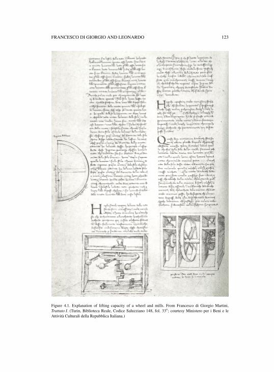
FRANCESCO DI GIORGIO AND LEONARDO 123
Figure 4.1. Explanation of lifting capacity of a wheel and mills. From Francesco di Giorgio Martini,Trattato I. (Turin, Biblioteca Reale, Codice Saluzziano 148, fol. 33v; courtesy Ministero per i Beni e leAttività Culturali della Repubblica Italiana.)
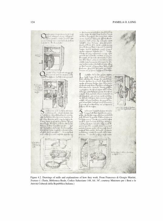
124 PAMELA O. LONG
Figure 4.2. Drawings of mills and explanations of how they work. From Francesco di Giorgio Martini,Trattato I. (Turin, Biblioteca Reale, Codice Saluzziano 148, fol. 34r; courtesy Ministero per i Beni e leAttività Culturali della Repubblica Italiana.)
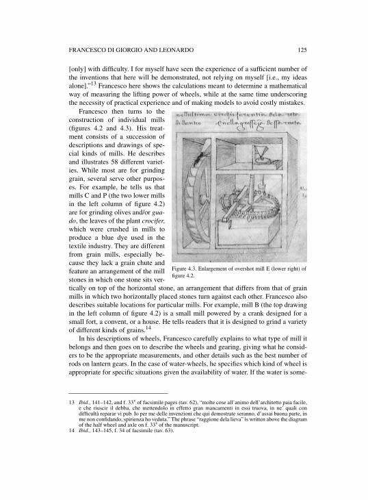
FRANCESCO DI GIORGIO AND LEONARDO 125
[only] with difficulty. I for myself have seen the experience of a sufficient number ofthe inventions that here will be demonstrated, not relying on myself [i.e., my ideasalone].”13 Francesco here shows the calculations meant to determine a mathematicalway of measuring the lifting power of wheels, while at the same time underscoringthe necessity of practical experience and of making models to avoid costly mistakes.
Francesco then turns to theconstruction of individual mills(figures 4.2 and 4.3). His treat-ment consists of a succession ofdescriptions and drawings of spe-cial kinds of mills. He describesand illustrates 58 different variet-ies. While most are for grindinggrain, several serve other purpos-es. For example, he tells us thatmills C and P (the two lower millsin the left column of figure 4.2)are for grinding olives and/or gua-do, the leaves of the plant crocifer,which were crushed in mills toproduce a blue dye used in thetextile industry. They are differentfrom grain mills, especially be-cause they lack a grain chute andfeature an arrangement of the millstones in which one stone sits ver-tically on top of the horizontal stone, an arrangement that differs from that of grainmills in which two horizontally placed stones turn against each other. Francesco alsodescribes suitable locations for particular mills. For example, mill B (the top drawingin the left column of figure 4.2) is a small mill powered by a crank designed for asmall fort, a convent, or a house. He tells readers that it is designed to grind a varietyof different kinds of grains.14
In his descriptions of wheels, Francesco carefully explains to what type of mill itbelongs and then goes on to describe the wheels and gearing, giving what he consid-ers to be the appropriate measurements, and other details such as the best number ofrods on lantern gears. In the case of water-wheels, he specifies which kind of wheel isappropriate for specific situations given the availability of water. If the water is some-
13 Ibid., 141–142, and f. 33v of facsimile pages (tav. 62), “molte cose all’animo dell’architetto paia facile,e che riuscir il debba, che mettendolo in effetto gran mancamenti in essi truova, in ne’ quali condifficultà reparar vi pub. Io per me delle invenzioni che qui demostrate seranno, d’assai buona parte, inme non confidando, spirienza ho veduta.” The phrase “raggione dela lieva” is written above the diagramof the half wheel and axle on f. 33v of the manuscript.
14 Ibid., 143–145, f. 34 of facsimile (tav. 63).
Figure 4.3. Enlargement of overshot mill E (lower right) offigure 4.2.
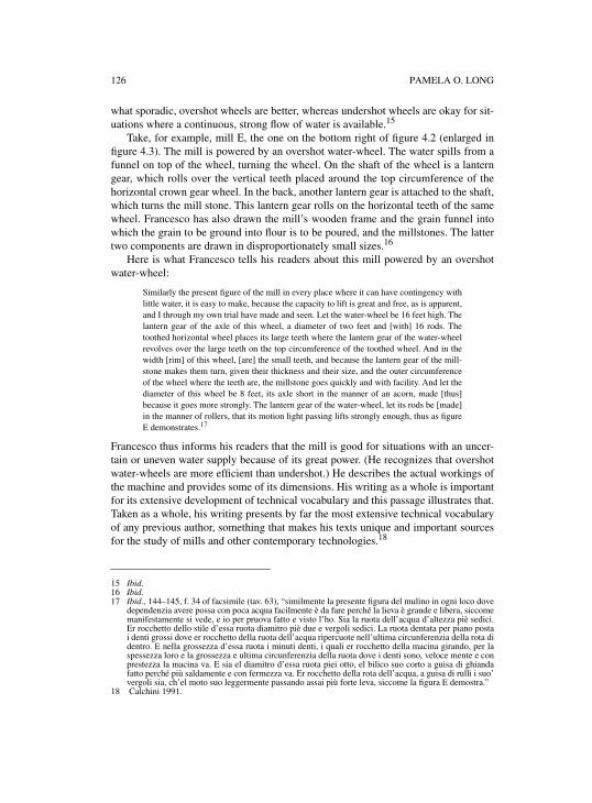
126 PAMELA O. LONG
what sporadic, overshot wheels are better, whereas undershot wheels are okay for sit-uations where a continuous, strong flow of water is available.15
Take, for example, mill E, the one on the bottom right of figure 4.2 (enlarged infigure 4.3). The mill is powered by an overshot water-wheel. The water spills from afunnel on top of the wheel, turning the wheel. On the shaft of the wheel is a lanterngear, which rolls over the vertical teeth placed around the top circumference of thehorizontal crown gear wheel. In the back, another lantern gear is attached to the shaft,which turns the mill stone. This lantern gear rolls on the horizontal teeth of the samewheel. Francesco has also drawn the mill’s wooden frame and the grain funnel intowhich the grain to be ground into flour is to be poured, and the millstones. The lattertwo components are drawn in disproportionately small sizes.16
Here is what Francesco tells his readers about this mill powered by an overshotwater-wheel:
Similarly the present figure of the mill in every place where it can have contingency withlittle water, it is easy to make, because the capacity to lift is great and free, as is apparent,and I through my own trial have made and seen. Let the water-wheel be 16 feet high. Thelantern gear of the axle of this wheel, a diameter of two feet and [with] 16 rods. Thetoothed horizontal wheel places its large teeth where the lantern gear of the water-wheelrevolves over the large teeth on the top circumference of the toothed wheel. And in thewidth [rim] of this wheel, [are] the small teeth, and because the lantern gear of the mill-stone makes them turn, given their thickness and their size, and the outer circumferenceof the wheel where the teeth are, the millstone goes quickly and with facility. And let thediameter of this wheel be 8 feet, its axle short in the manner of an acorn, made [thus]because it goes more strongly. The lantern gear of the water-wheel, let its rods be [made]in the manner of rollers, that its motion light passing lifts strongly enough, thus as figureE demonstrates.17
Francesco thus informs his readers that the mill is good for situations with an uncer-tain or uneven water supply because of its great power. (He recognizes that overshotwater-wheels are more efficient than undershot.) He describes the actual workings ofthe machine and provides some of its dimensions. His writing as a whole is importantfor its extensive development of technical vocabulary and this passage illustrates that.Taken as a whole, his writing presents by far the most extensive technical vocabularyof any previous author, something that makes his texts unique and important sourcesfor the study of mills and other contemporary technologies.18
15 Ibid.16 Ibid.17 Ibid., 144–145, f. 34 of facsimile (tav. 63), “similmente la presente figura del mulino in ogni loco dove
dependenzia avere possa con poca acqua facilmente è da fare perché la lieva è grande e libera, siccomemanifestamente si vede, e io per pruova fatto e visto l’ho. Sia la ruota dell’acqua d’altezza piè sedici.Er rocchetto dello stile d’essa ruota diamitro piè due e vergoli sedici. La ruota dentata per piano postai denti grossi dove er rocchetto della ruota dell’acqua ripercuote nell’ultima circunferenzia della rota didentro. E nella grossezza d’essa ruota i minuti denti, i quali er rocchetto della macina girando, per laspessezza loro e la grossezza e ultima circunferenzia della ruota dove i denti sono, veloce mente e conprestezza la macina va. E sia el diamitro d’essa ruota piei otto, el bilico suo corto a guisa di ghiandafatto perché più saldamente e con fermezza va. Er rocchetto della rota dell’acqua, a guisa di rulli i suo’vergoli sia, ch’el moto suo leggermente passando assai più forte leva, siccome la figura E demostra.”
18 Calchini 1991.

FRANCESCO DI GIORGIO AND LEONARDO 127
In Trattato I Francesco provides a detailed written account, illustrated by numer-ous drawings, of his architectural and engineering knowledge. Mills were essentialelements of many building projects from castles to forts, and they were also essentialto any town or city. Taken as a whole, Francesco provides numerous examples ofvariations. Knowledge of such variations was essential to any practising architect/engineer of his time. Presented with variations of geography, power supply andpotential use, the master must devise or decide upon a mill with particular character-istics for specific sites. Yet Francesco was not writing a manual for other practitio-ners. Rather, he was detailing his knowledge of practice in a codex at the instigationof his patron, Federico da Montefeltre, for the benefit of a more elite readership. Theprofessionally copied text and carefully drawn images, on vellum bound in leather,consisted of a display of engineering knowledge for patrons, not a manual for use byother practitioners. Nevertheless, Francesco’s careful detailing of numerous varia-tions points to his close identification with the concerns of practicing engineers, agroup that included himself.
Francesco’s later treatise, Trattato II, is extant in two copies, one in Siena (S.IV.4),known as S (the earlier version) and another, Magliabecchiano (II.I.141) in Florence,known as M. Trattato II is organized differently from Trattato I, with fewer chapters,the addition of learned introductions, and more frequent references to ancient textssuch as the Naturalis historia of Pliny and the De architectura of Vitruvius. Some ofthe more general topics of Trattato I survive as chapters in the later treatise, for exam-ple, the city, temples, fortresses, and harbours. Corrado Maltese, the editor of the1967 edition of the treatise, supposed that it was the work of a humanist hired torevise Francesco’s earlier treatise. The more recent investigations of Mussini, how-ever, underscore that the treatise is the work of Francesco himself, with only shortintroductory passages added by another. This later treatise reflects Francesco’sgreater knowledge of Vitruvius. In addition, he provides more general treatments. Hehas moved from detailing many particular mills in Trattato I to more general accountsof far fewer mills, an approach more suitable to a readership of patrons and univer-sity-educated men.19
Trattato II is divided into seven books or trattati, as Francesco himself calledthem. There is a preamble, a book of common principles and norms, and then treat-ments of houses, ways to find water, castles and cities, temples, forts, ports, and asection on machines, “Machines to pull weights and conduct water, and mills,” andthen a conclusion. The material on machines that was scattered among various sec-tions of Trattato I has received a new treatment in this treatise in one section only,section seven, which concerns lifting machines of various kinds and mills. In all,eighteen machines are displayed in drawings and described, a radical reduction fromthe earlier work, which contains drawings and descriptions of 58 mills alone, and
19 Francesco di Giorgio Martini 1967, I xi–xlviii; Mussini 1993, 358–359. The Magliabecchianomanuscripts contain several other works by Francesco as well—the Trattato is on ff. 1–102, Francesco’stranslation of Vitruvius on ff.103–192, and on ff. 193–244v a collection of drawings of militarymachines and fortification designs.
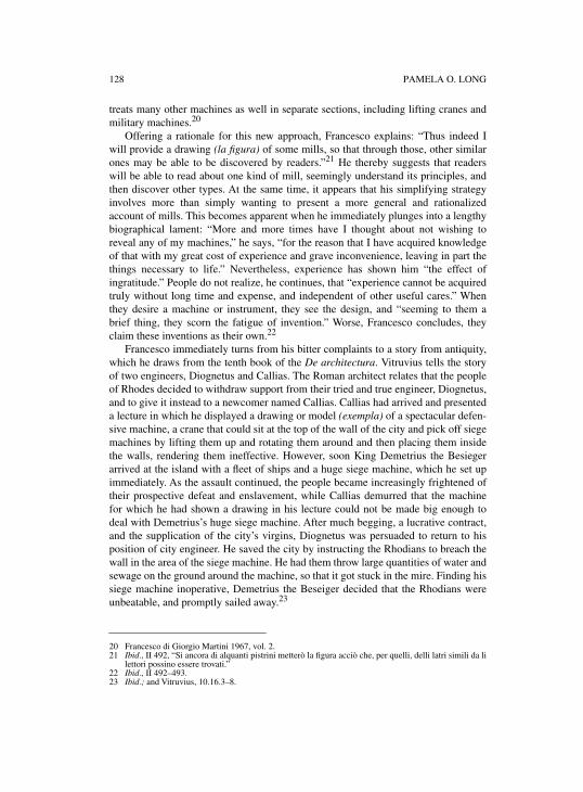
128 PAMELA O. LONG
treats many other machines as well in separate sections, including lifting cranes andmilitary machines.20
Offering a rationale for this new approach, Francesco explains: “Thus indeed Iwill provide a drawing (la figura) of some mills, so that through those, other similarones may be able to be discovered by readers.”21 He thereby suggests that readerswill be able to read about one kind of mill, seemingly understand its principles, andthen discover other types. At the same time, it appears that his simplifying strategyinvolves more than simply wanting to present a more general and rationalizedaccount of mills. This becomes apparent when he immediately plunges into a lengthybiographical lament: “More and more times have I thought about not wishing toreveal any of my machines,” he says, “for the reason that I have acquired knowledgeof that with my great cost of experience and grave inconvenience, leaving in part thethings necessary to life.” Nevertheless, experience has shown him “the effect ofingratitude.” People do not realize, he continues, that “experience cannot be acquiredtruly without long time and expense, and independent of other useful cares.” Whenthey desire a machine or instrument, they see the design, and “seeming to them abrief thing, they scorn the fatigue of invention.” Worse, Francesco concludes, theyclaim these inventions as their own.22
Francesco immediately turns from his bitter complaints to a story from antiquity,which he draws from the tenth book of the De architectura. Vitruvius tells the storyof two engineers, Diognetus and Callias. The Roman architect relates that the peopleof Rhodes decided to withdraw support from their tried and true engineer, Diognetus,and to give it instead to a newcomer named Callias. Callias had arrived and presenteda lecture in which he displayed a drawing or model (exempla) of a spectacular defen-sive machine, a crane that could sit at the top of the wall of the city and pick off siegemachines by lifting them up and rotating them around and then placing them insidethe walls, rendering them ineffective. However, soon King Demetrius the Besiegerarrived at the island with a fleet of ships and a huge siege machine, which he set upimmediately. As the assault continued, the people became increasingly frightened oftheir prospective defeat and enslavement, while Callias demurred that the machinefor which he had shown a drawing in his lecture could not be made big enough todeal with Demetrius’s huge siege machine. After much begging, a lucrative contract,and the supplication of the city’s virgins, Diognetus was persuaded to return to hisposition of city engineer. He saved the city by instructing the Rhodians to breach thewall in the area of the siege machine. He had them throw large quantities of water andsewage on the ground around the machine, so that it got stuck in the mire. Finding hissiege machine inoperative, Demetrius the Beseiger decided that the Rhodians wereunbeatable, and promptly sailed away.23
20 Francesco di Giorgio Martini 1967, vol. 2.21 Ibid., II 492, “Si ancora di alquanti pistrini metterò la figura acciò che, per quelli, delli latri simili da li
lettori possino essere trovati.”22 Ibid., II 492–493. 23 Ibid.; and Vitruvius, 10.16.3–8.
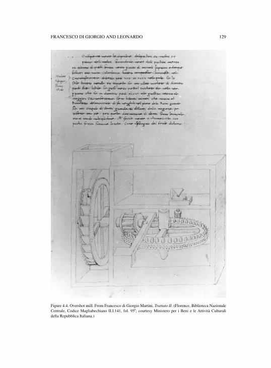
FRANCESCO DI GIORGIO AND LEONARDO 129
Figure 4.4. Overshot mill. From Francesco di Giorgio Martini, Trattato II. (Florence, Biblioteca NazionaleCentrale, Codice Magliabechiano II.I.141, fol. 95r; courtesy Ministero per i Beni e le Attività Culturalidella Repubblica Italiana.)
130 PAMELA O. LONG
The story underscores the importance of loyalty to a trusted architect and engi-neer, and it also suggests that actual practice is far more important than the theoreticalknowledge presented in a lecture. Its appeal to Francesco undoubtedly also rested inits vivid account of the role of a drawing. By means of this ancient story, Francescounderscores the point that neither models nor drawings can be easily transformed intoan actual working machine, primarily because they do not forewarn about problemsarising due to different scales. While Vitruvius used one word, exempla, to explainwhat Callias displayed to the Rhodians, Francesco uses two—“some models anddesigns of machines” (alcuni modelli e disegni di macchine). It is best not to trustthose who have merely taken a model or drawing from someone else, such as,Francesco might as well add, those who had stolen drawings from him. Drawingscannot substitute for actual machines, nor can an “ignorant and presumptuous” archi-tect like Callias stand in for the experience of an “ingenious and expert architect” likeDiognetes—or indeed, like Francesco di Giorgio himself.
Francesco then proceeds to a discussion of machines. Of the eighteen machineshe treats, there are six kinds of argani, or lifting machines comprised of capstans orwindlasses, four kinds of viti, machines for lifting or pulling using screws, a waterpump, and eight mills, including six dry mills or pistrini (including a windmill), andtwo water-mills or mulini, one powered by a horizontal wheel and the other poweredby an overshot water-wheel.24
Francesco discusses only one type of overshot water-wheel mill, which he drawsin a large size on a single page underneath the text describing it (figure 4.4). Thismachine is similar to the overshot wheel discussed above, one of five (E) on the sheetin Trattato I (figure 4.2, lower right and figure 4.3). His description in the later trea-tise is similar, but not the same as that for the analogous machine in Trattato I. Hegives the dimensions of various parts such as the water-wheel and the crown-wheel.He explains that the wheel turns easily because the vertical teeth on top rim of thecrown-gear are larger than the horizontal teeth on the lateral rim, and there are fewerof them. The smaller teeth on the lateral rim of the crown-wheel turn the smaller lan-tern wheel attached to the axle that turns the millstone. The drawing clearly shows thedifference in size and number of the two rows of teeth on the crown-gear wheel. Italso shows the different sizes of the two lantern gears, the one on the axle of thewater-wheel being larger than that on the millstone axle. Francesco explains thatthese differences in the size of the teeth in the crown-wheel and the size of the lanterngears are what make the machine turn easily. It is notable that in his earlier drawingof the analogous machine such differences are not apparent in the drawing, nor doesthe explanation concerning ease of motion appear in the text. This is an example then,of using one machine to explain a more general principle (that of the gear differen-tial), instead of enumerating varieties of mills suitable for diverse situations.25
The changes that are apparent between Trattato I and Trattato II are indicative ofFrancesco’s efforts to write a more learned treatise, efforts that were influenced by
24 Francesco di Giorgio Martini 1967, II 495–504 and tav. 317–331.25 Ibid., II 500–501; and f. 95 (tav. 325). Cf. ibid., I 492–493 and fol. 34 (tav. 63).
FRANCESCO DI GIORGIO AND LEONARDO 131
humanist practices of authorship. Rather than showing a large variety of particularmachines, he discusses a smaller number chosen on the basis of types (for example,as we have seen, he discusses only one overshot water-wheel mill). He devotes morespace and larger drawings to each type. He also begins each chapter with a generalintroduction, and refers often to ancient passages relevant to the topics that he treats.In Francesco’s treatises, it is notable that the engineer becomes visible as an individ-ual who suffers the hardships of invention, and works as a practitioner. Francescodecries the thefts of invention and the patrons’ reliance on drawings alone rather thanon the engineer’s extensive practice. In Trattato II especially, the human engineeremerges as a striking figure. This is in part a result of Francesco’s engagement withthe De architectura and other ancient texts, and in part the result of his engagementwith contemporary humanist writings such as the treatises of Alberti, Valturio, andFilarete.26
2. LEONARDO DA VINCI AND THE ELEMENTS OF MACHINES
In the early 1490s when Leonardo da Vinci (1452–1519) was working on Madrid I,he had extensive contact with Francesco di Giorgio when they were both consultantson the cathedral of Pavia. Possibly they had met earlier, in the late 1480s. Leonardo’sproject of a treatise on machines and mechanics clearly came about at least in partbecause of the influence of Francesco di Giorgio. In turn, Francesco was influencedby the earlier Sienese author of machine writings, Mariano Taccola. Francesco cop-ied some of Taccola’s text into his own notebooks, especially the small, early note-book referred to as the codicetto. Similarly, Leonardo copied some of Francesco’stext into Madrid Codex I. And as mentioned previously, Leonardo put his own nota-tions on several sheets of the manuscript copy of Trattato I, Ashburnham 361, now inFlorence. Clearly Francesco di Giorgio and Leonardo influenced each other; theirwork contains common elements, but can also be distinguished in fundamentalways.27
Madrid I (Ms. 8937 of the Biblioteca Nacional in Madrid) consists of two note-books that, it has been argued cogently, were bound together by Leonardo himself. Inthe first half, up to folio 92, the folios progress forward in normal fashion from left toright, written of course in Leonardo’s characteristic mirror script. It consists of a trea-tise on practical mechanics and elements of machines. Leonardo numbered this halfof the codex on the rectos of each folio through the first six quires. The second half ofthe work progresses backwards from the back of the treatise toward the centre—fromright to left. It consists of the more theoretical part of the work—a treatise on the sci-ence of weights (scientia de ponderibus). Leonardo numbered this half in mirrornumbers on the verso starting at the back and going towards the front (folios 95–191in the current foliation). All the sheets of both halves are the same size, all bear thesame recurring watermark, and the whole contains only two protective flyleaves.28
26 See Grafton 2000; Long 2001, 122–133; Filarete (Antonio Averlino) 1972.27 Galluzzi 1991; Johnston 2000, 24–105; Pedretti 1985; Tocci 1962; and Zwijnenberg 1999, esp. 35–46.
132 PAMELA O. LONG
Madrid I contains many illustrations of machines and devices, which in part comeout of Leonardo’s studies of motion, but which are also grounded in his practice as anengineer. In the 1490s Leonardo was a client of the Sforza family in Milan, patronagethat he acquired primarily on the basis of his abilities as an engineer and productiveartist. Sforza patronage was bestowed on a group that included both learned human-ists and artisan practitioners including Leonardo. The Sforza created a court that pro-duced painting, sculpture, and buildings to their greater glory. They also strenuouslyinvolved themselves in the armaments industry and in canal building undertaken toimprove transportation and agriculture primarily for commercial purposes. Courtpatronage, material production, and commerce were closely interrelated endeavors.29
The first half of Madrid I is filled with beautiful drawings of machines anddevices, and machine parts surrounded by detailed textual explanations concerninghow they work and how they demonstrate the ways in which the natural world works.It treats the motions of toothed wheels, springs, clock escapement mechanisms (whatLeonardo calls tempi), continuous and discontinuous motions of various sorts—counterweights, chain gears, screws, pinions and wheels, endless screws, liftingdevices, mills, keys and locks, and crossbows, among others. There is evidence thatLeonardo carefully planned his treatise. In an examination of the manuscript inMadrid, Marina Johnston has recently discovered that the drawings were made firstby creating preparatory drawings with metal or bone point before ink was applied.Other evidence of careful preparation includes sheets in the Codex Atlanticus inMilan that contain drawings that are repeated in Madrid I as well as blocks of text,crossed out, that are carefully written into Madrid I. It is clear in many cases thatLeonardo drew the images first and then wrote around them. Detailed investigation ofthe specific pictorial and textual content of single sheets in the codex is particularlyfruitful since many of the sheets function more or less as self-contained units on asingle topic or on two or more related topics.30
For example, on folio 0 verso are two lines stating the subjects at hand. A singleline on the right reads “On the Placing of the Figure” (Del posare della figura) (fig-ure 4.5). On the left is the two line heading: “Book entitled of quantity and Power”(Libro titolato de quantità e potentia). Below these two headings is a paragraph,which (I surmise) Leonardo added at a time later than when he created the rest of thepage, inserting a comment into an available space. This comment concerns a nineyear old boy named Taddeo who played the lute in Milan on Sept. 28, 1497 and whois considered the best lute player in Italy. Below the passage about Taddeo is drawnthe figure of a crank mechanism. The crank itself can be seen in the back of an appa-
28 Leonardo 1974, vol. 3 (Reti’s introduction to the codices); and Johnston 2000, 24–105, who providesa cogent analysis of the structure of the manuscript that adds significantly to Reti’s foundationaldiscussion; and see Maschat 1989.
29 For the Sforza court as it developed, see Catalano 1983; Chittolini 1989; Ianziti 1988; Lubkin 1994;and Welch 1996. For Milanese canal building, see Parsons 1968, 367–419.
30 Leonardo 1974, I f. 9r, IV 24–25 (springs, clock escapements, continuous and discontinuous motions);I f. 10r, IV 27–28 (chain gears); I f. 15r, IV 39–40 (screws); I f. 19r, IV 47–48 (endless screws); and I f.46v, IV 89–90 (mills). For a discussion of the organization of the work as a whole and of individualpages, see esp. Johnston 2000, 24–105; and see Zwijnenberg 1999, 100.
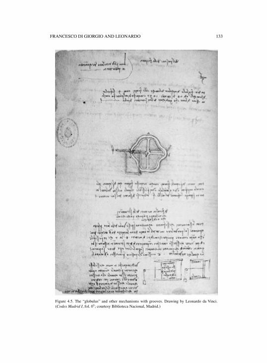
FRANCESCO DI GIORGIO AND LEONARDO 133
Figure 4.5. The “globulus” and other mechanisms with grooves. Drawing by Leonardo da Vinci.(Codex Madrid I, fol. 0v; courtesy Biblioteca Nacional, Madrid.)
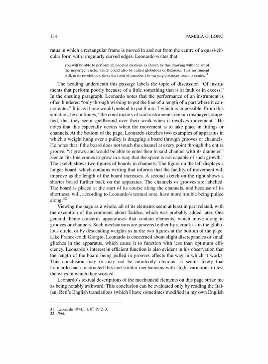
134 PAMELA O. LONG
ratus in which a rectangular frame is moved in and out from the centre of a quasi-cir-cular form with irregularly curved edges. Leonardo writes that
you will be able to perform all unequal motions as shown by this drawing with the art ofthe imperfect circle, which could also be called globulous or flexuous. This instrumentwill, in its revolutions, drive the front of member f to varying distances from its center.31
The heading underneath this passage labels the topic of discussion “Of instru-ments that perform poorly because of a little something that is at fault or in excess.”In the ensuing paragraph, Leonardo notes that the performance of an instrument isoften hindered “only through wishing to put the line of a length of a part where it can-not enter.” It is as if one would pretend to put 8 into 7 which is impossible. From thissituation, he continues, “the constructors of said instruments remain dismayed, stupe-fied, that they seem spellbound over their work when it involves movement.” Henotes that this especially occurs when the movement is to take place in fittings orchannels. At the bottom of the page, Leonardo sketches two examples of apparatus inwhich a weight hung over a pulley is dragging a board through grooves or channels.He notes that if the board does not touch the channel at every point through the entiregroove, “it grows and would be able to enter then in said channel with its diameter.”Hence “its line comes to grow in a way that the space is not capable of such growth.”The sketch shows two figures of boards in channels. The figure on the left displays alonger board, which contains writing that informs that the facility of movement willimprove as the length of the board increases. A second sketch on the right shows ashorter board further back on the apparatus. The channels or grooves are labelled.The board is placed at the start of its course along the channels, and because of itsshortness, will, according to Leonardo’s textual note, have more trouble being pulledalong.32
Viewing the page as a whole, all of its elements seem at least in part related, withthe exception of the comment about Taddeo, which was probably added later. Onegeneral theme concerns apparatuses that contain elements, which move along ingrooves or channels. Such mechanisms are powered either by a crank as in the globu-lous circle, or by descending weights as in the two figures at the bottom of the page.Like Francesco di Giorgio, Leonardo is concerned about slight discrepancies or smallglitches in the apparatus, which cause it to function with less than optimum effi-ciency. Leonardo’s interest in efficient function is also evident in his observation thatthe length of the board being pulled in grooves affects the way in which it works.This conclusion may or may not be intuitively obvious—it seems likely thatLeonardo had constructed this and similar mechanisms with slight variations to testthe ways in which they worked.
Leonardo’s textual descriptions of the mechanical elements on this page strike meas being notably awkward. This conclusion can be evaluated only by reading the Ital-ian; Reti’s English translations (which I have sometimes modified in my own English
31 Leonardo 1974, I f. 0v, IV 2–3.32 Ibid.
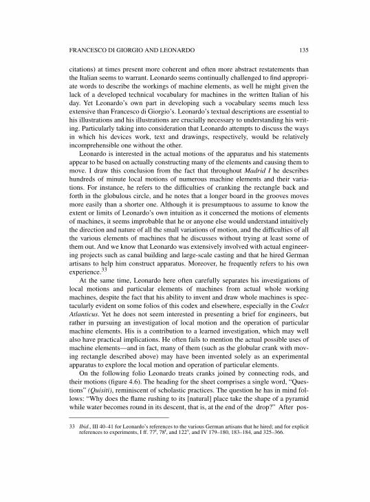
FRANCESCO DI GIORGIO AND LEONARDO 135
citations) at times present more coherent and often more abstract restatements thanthe Italian seems to warrant. Leonardo seems continually challenged to find appropri-ate words to describe the workings of machine elements, as well he might given thelack of a developed technical vocabulary for machines in the written Italian of hisday. Yet Leonardo’s own part in developing such a vocabulary seems much lessextensive than Francesco di Giorgio’s. Leonardo’s textual descriptions are essential tohis illustrations and his illustrations are crucially necessary to understanding his writ-ing. Particularly taking into consideration that Leonardo attempts to discuss the waysin which his devices work, text and drawings, respectively, would be relativelyincomprehensible one without the other.
Leonardo is interested in the actual motions of the apparatus and his statementsappear to be based on actually constructing many of the elements and causing them tomove. I draw this conclusion from the fact that throughout Madrid I he describeshundreds of minute local motions of numerous machine elements and their varia-tions. For instance, he refers to the difficulties of cranking the rectangle back andforth in the globulous circle, and he notes that a longer board in the grooves movesmore easily than a shorter one. Although it is presumptuous to assume to know theextent or limits of Leonardo’s own intuition as it concerned the motions of elementsof machines, it seems improbable that he or anyone else would understand intuitivelythe direction and nature of all the small variations of motion, and the difficulties of allthe various elements of machines that he discusses without trying at least some ofthem out. And we know that Leonardo was extensively involved with actual engineer-ing projects such as canal building and large-scale casting and that he hired Germanartisans to help him construct apparatus. Moreover, he frequently refers to his ownexperience.33
At the same time, Leonardo here often carefully separates his investigations oflocal motions and particular elements of machines from actual whole workingmachines, despite the fact that his ability to invent and draw whole machines is spec-tacularly evident on some folios of this codex and elsewhere, especially in the CodexAtlanticus. Yet he does not seem interested in presenting a brief for engineers, butrather in pursuing an investigation of local motion and the operation of particularmachine elements. His is a contribution to a learned investigation, which may wellalso have practical implications. He often fails to mention the actual possible uses ofmachine elements—and in fact, many of them (such as the globular crank with mov-ing rectangle described above) may have been invented solely as an experimentalapparatus to explore the local motion and operation of particular elements.
On the following folio Leonardo treats cranks joined by connecting rods, andtheir motions (figure 4.6). The heading for the sheet comprises a single word, “Ques-tions” (Quisiti), reminiscent of scholastic practices. The question he has in mind fol-lows: “Why does the flame rushing to its [natural] place take the shape of a pyramidwhile water becomes round in its descent, that is, at the end of the drop?” After pos-
33 Ibid., III 40–41 for Leonardo’s references to the various German artisans that he hired; and for explicitreferences to experiments, I ff. 77r, 78r, and 122v, and IV 179–180, 183–184, and 325–366.
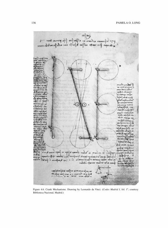
136 PAMELA O. LONG
Figure 4.6. Crank Mechanisms. Drawing by Leonardo da Vinci. (Codex Madrid I, fol. 1r; courtesyBiblioteca Nacional, Madrid.)
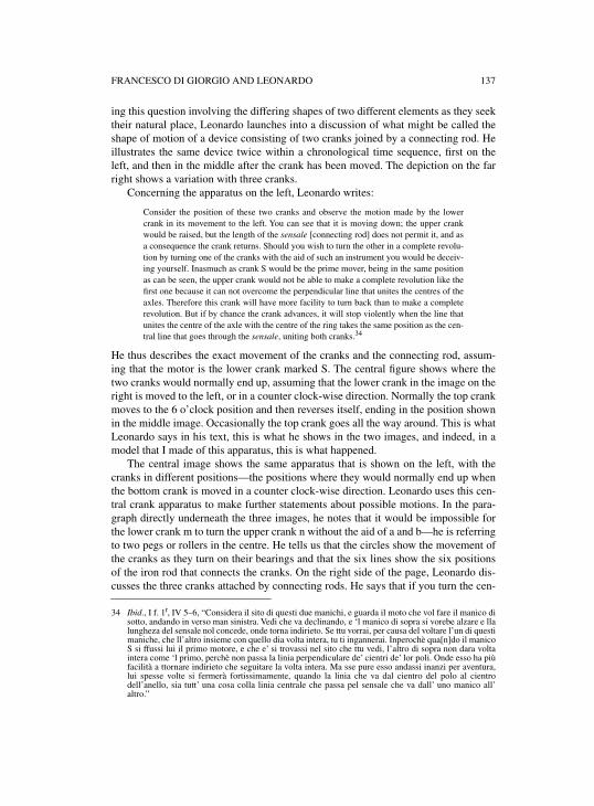
FRANCESCO DI GIORGIO AND LEONARDO 137
ing this question involving the differing shapes of two different elements as they seektheir natural place, Leonardo launches into a discussion of what might be called theshape of motion of a device consisting of two cranks joined by a connecting rod. Heillustrates the same device twice within a chronological time sequence, first on theleft, and then in the middle after the crank has been moved. The depiction on the farright shows a variation with three cranks.
Concerning the apparatus on the left, Leonardo writes:
Consider the position of these two cranks and observe the motion made by the lowercrank in its movement to the left. You can see that it is moving down; the upper crankwould be raised, but the length of the sensale [connecting rod] does not permit it, and asa consequence the crank returns. Should you wish to turn the other in a complete revolu-tion by turning one of the cranks with the aid of such an instrument you would be deceiv-ing yourself. Inasmuch as crank S would be the prime mover, being in the same positionas can be seen, the upper crank would not be able to make a complete revolution like thefirst one because it can not overcome the perpendicular line that unites the centres of theaxles. Therefore this crank will have more facility to turn back than to make a completerevolution. But if by chance the crank advances, it will stop violently when the line thatunites the centre of the axle with the centre of the ring takes the same position as the cen-tral line that goes through the sensale, uniting both cranks.34
He thus describes the exact movement of the cranks and the connecting rod, assum-ing that the motor is the lower crank marked S. The central figure shows where thetwo cranks would normally end up, assuming that the lower crank in the image on theright is moved to the left, or in a counter clock-wise direction. Normally the top crankmoves to the 6 o’clock position and then reverses itself, ending in the position shownin the middle image. Occasionally the top crank goes all the way around. This is whatLeonardo says in his text, this is what he shows in the two images, and indeed, in amodel that I made of this apparatus, this is what happened.
The central image shows the same apparatus that is shown on the left, with thecranks in different positions—the positions where they would normally end up whenthe bottom crank is moved in a counter clock-wise direction. Leonardo uses this cen-tral crank apparatus to make further statements about possible motions. In the para-graph directly underneath the three images, he notes that it would be impossible forthe lower crank m to turn the upper crank n without the aid of a and b—he is referringto two pegs or rollers in the centre. He tells us that the circles show the movement ofthe cranks as they turn on their bearings and that the six lines show the six positionsof the iron rod that connects the cranks. On the right side of the page, Leonardo dis-cusses the three cranks attached by connecting rods. He says that if you turn the cen-
34 Ibid., I f. 1r, IV 5–6, “Considera il sito di questi due manichi, e guarda il moto che vol fare il manico disotto, andando in verso man sinistra. Vedi che va declinando, e ‘l manico di sopra si vorebe alzare e llalungheza del sensale nol concede, onde torna indirieto. Se ttu vorrai, per causa del voltare l’un di questimaniche, che ll’altro insieme con quello dia volta intera, tu ti ingannerai. Inperochè qua[n]do il manicoS si ffussi lui il primo motore, e che e’ si trovassi nel sito che ttu vedi, l’altro di sopra non dara voltaintera come ‘l primo, perchè non passa la linia perpendiculare de’ cientri de’ lor poli. Onde esso ha piùfacilità a ttornare indirieto che seguitare la volta intera. Ma sse pure esso andassi inanzi per aventura,lui spesse volte si fermerà fortissimamente, quando la linia che va dal cientro del polo al cientrodell’anello, sia tutt’ una cosa colla linia centrale che passa pel sensale che va dall’ uno manico all’altro.”
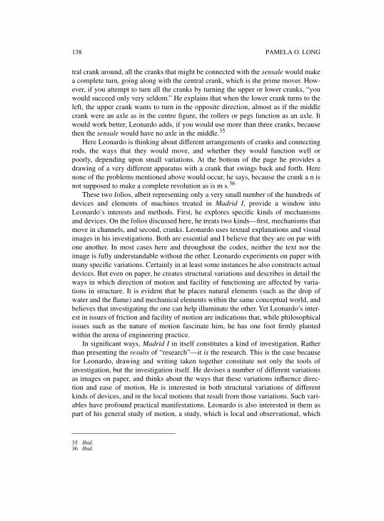
138 PAMELA O. LONG
tral crank around, all the cranks that might be connected with the sensale would makea complete turn, going along with the central crank, which is the prime mover. How-ever, if you attempt to turn all the cranks by turning the upper or lower cranks, “youwould succeed only very seldom.” He explains that when the lower crank turns to theleft, the upper crank wants to turn in the opposite direction, almost as if the middlecrank were an axle as in the centre figure, the rollers or pegs function as an axle. Itwould work better, Leonardo adds, if you would use more than three cranks, becausethen the sensale would have no axle in the middle.35
Here Leonardo is thinking about different arrangements of cranks and connectingrods, the ways that they would move, and whether they would function well orpoorly, depending upon small variations. At the bottom of the page he provides adrawing of a very different apparatus with a crank that swings back and forth. Herenone of the problems mentioned above would occur, he says, because the crank a n isnot supposed to make a complete revolution as is m s.36
These two folios, albeit representing only a very small number of the hundreds ofdevices and elements of machines treated in Madrid I, provide a window intoLeonardo’s interests and methods. First, he explores specific kinds of mechanismsand devices. On the folios discussed here, he treats two kinds—first, mechanisms thatmove in channels, and second, cranks. Leonardo uses textual explanations and visualimages in his investigations. Both are essential and I believe that they are on par withone another. In most cases here and throughout the codex, neither the text nor theimage is fully understandable without the other. Leonardo experiments on paper withmany specific variations. Certainly in at least some instances he also constructs actualdevices. But even on paper, he creates structural variations and describes in detail theways in which direction of motion and facility of functioning are affected by varia-tions in structure. It is evident that he places natural elements (such as the drop ofwater and the flame) and mechanical elements within the same conceptual world, andbelieves that investigating the one can help illuminate the other. Yet Leonardo’s inter-est in issues of friction and facility of motion are indications that, while philosophicalissues such as the nature of motion fascinate him, he has one foot firmly plantedwithin the arena of engineering practice.
In significant ways, Madrid I in itself constitutes a kind of investigation. Ratherthan presenting the results of “research”—it is the research. This is the case becausefor Leonardo, drawing and writing taken together constitute not only the tools ofinvestigation, but the investigation itself. He devises a number of different variationsas images on paper, and thinks about the ways that these variations influence direc-tion and ease of motion. He is interested in both structural variations of differentkinds of devices, and in the local motions that result from those variations. Such vari-ables have profound practical manifestations. Leonardo is also interested in them aspart of his general study of motion, a study, which is local and observational, which
35 Ibid.36 Ibid.
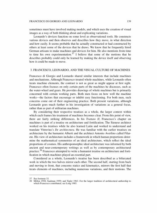
FRANCESCO DI GIORGIO AND LEONARDO 139
sometimes must have involved making models, and which uses the creation of visualimages as a way of both thinking about and explicating variations.
Leonardo’s devices function on some level as observational tools. He constructsvarious devices and then observes and describes how they move, in what directionand how easily. It seems probable that he actually constructed or had constructed byothers at least some of the devices that he draws. We know that he frequently hiredGerman artisans to make machines and devices for him. He also mentions from timeto time his own experimentation.37 I believe that some of the motions that hedescribes probably could only be learned by making the device itself and observinghow it could be made to move.
3. FRANCESCO, LEONARDO, AND THE VISUAL CULTURE OF MACHINES
Francesco di Giorgio and Leonardo shared similar interests that include machinesand mechanisms. Although Francesco treated whole machines, while Leonardo oftentreats machine elements, the contrast is not as great as might appear at first sight.Francesco often focuses on only certain parts of the machines he discusses, such asthe water-wheel and gears. He provides drawings of whole machines but is primarilyconcerned with certain working parts. Both men focus on how well the machineworks—the factors that encourage or inhibit easy functioning. For both men, suchconcerns come out of their engineering practice. Both present variations, althoughLeonardo goes much further in his investigation of variations as a general focus,rather than as part of utilitarian machines.
By considering their respective treatises as a whole, the larger context withinwhich each frames his treatment of machines becomes clear. From this point of view,there are fairly striking differences. In his Trattato II, Francesco’s chapter onmachines is part of a treatise on architecture and fortification. The Sienese architectworked on his treatises while he also learned Latin and worked to understand andtranslate Vitruvius’s De architectura. He was familiar with the earlier treatises onarchitecture by the humanist Alberti and the architect Antonio Averlino called Filar-ete. His view of architecture includes a framework in which human proportions deter-mine the mathematical symmetries of an ideal architecture, which reflect the idealproportions of cosmos. His anthropomorphic ideal architecture was informed by bothancient and near-contemporary writings as well as by contemporary architecturalpractice.38 Francesco attempted to write a humanist treatise on architecture and forti-fication in which machines played an essential part.
Considered as a whole, Leonardo’s treatise has been described as a bifurcatedwork in which the two halves mirror each other. The second half, starting from backand moving to front, that concerns statics and kinematics, mirrors the first half thattreats elements of machines, including numerous variations, and their motions. The
37 See footnote 33.38 Millon 1958; Saalman 1959; and Tigler 1963. For the larger tradition of architectural authorship to
which Francesco contributed, see Long 1985.
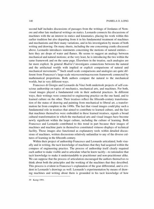
140 PAMELA O. LONG
second half includes discussions of passages from the writings of Jordanus of Nem-ore and other late mediaeval writings on statics. Leonardo connects his discussions ofmachines with the an interest in statics and kinamatics, placing his work within thisearlier tradition but also departing from it in his fundamental treatment of machinesand mechanisms and their many variations, and in his investigation by means of bothwriting and drawing. On many sheets, including the one concerning cranks discussedabove, Leonardo introduces statements concerning the motions of natural entities—here they are drops of water and flames. He seems to suggest an analogy betweenmechanical and natural motions; at the very least, he is introducing the two within thesame framework and on the same page. Elsewhere in the treatise, such analogies arefar more explicit. In general Madrid I investigates connections between the naturaland the artifactual worlds with implied or explicit comparisons of natural andmechanical movements.39 Such small-scale comparisons and analogies are quite dif-ferent from Francesco’s large-scale microcosm/macrocosm framework connected bymathematical proportions. Both authors compare the natural to the mechanicalworlds, but in very different ways.
Francesco di Giorgio and Leonardo da Vinci both undertook projects of self-con-scious authorship on topics of mechanics, mechanical arts, and machines. For both,visual images played a fundamental role in their authorial practices. In differentways, their writings were connected to engineering practice on the one hand, and tolearned culture on the other. Their treatises reflect the fifteenth-century transforma-tion of the status of drawing and painting from mechanical to liberal art, a transfor-mation far from complete in the 1490s. The fact that visual images could play such afundamental role in treatises that aimed to contribute to learned culture, and the factthat machines themselves were embedded in these learned treatises, signals a broadcultural transformation in which the mechanical arts and visual images have becomenewly significant within the larger culture, including the culture of learning. BothFrancesco and Leonardo contributed to this trend in part because their images ofmachines and machine parts in themselves constituted virtuoso displays of technicalfacility. Those images also functioned as explanatory tools within detailed discus-sions of machines, written discussions relatively unfamiliar to any of the diverse cul-tures of learning in the fifteenth century.
Within their project of authorship Francesco and Leonardo articulated, both visu-ally and in writing, the tacit knowledge of machines that they had acquired within thecompass of engineering practice. The process of authorship itself clearly requiredeach author to make visible and to articulate what he knew tacitly—to rationalize thattacit knowledge to make it understandable to practitioner and non-practitioner alike.We can suppose that the process of articulation encouraged the authors themselves tothink about both the principles and the working of the machines that they described.This process is evident in Francesco’s explanation of the gear differential, and is evi-dent in Leonardo’s drawings as well. Leonardo’s experimentation by means of draw-ing machines and writing about them is grounded in his tacit knowledge of how
39 Kemp 1991.
FRANCESCO DI GIORGIO AND LEONARDO 141
machines are made and how they work. What is not always clear is the location of theline between what he knows tacitly and what he learns from the process of drawingand writing about mechanisms. Both authors make the tacit knowledge of their ownpractice available to readers, including learned readers who would not have possessedsuch knowledge.
In this chapter I have compared Francesco di Giorgio and Leonardo’s treatmentsof machines, and pointed to their shared culture of engineering practice, and theircommon experience of functioning within client/patronage relationships. I havepointed to their substantial intellectual similarities and their significant differences.What I have not done is suggest that Leonardo’s work represents an “advance” overthat of Francesco di Giorgio’s. Rather, each author identified with and developed hiswriting within the context of diverse strands of contemporary learned culture—Francesco within the context of humanist writing, Leonardo within the context ofscholastic traditions. I would suggest that their two diverse ways of relating to andadvancing learned culture point significantly to transformations within that culture.
Neither the writings of Francesco or Leonardo represent a point within a lineardevelopment to “classical” mechanics. At least in some cases, as Michael Mahoneyhas emphasized, classical mechanics as it developed in the seventeenth centurymoved toward increasing use of mathematics and greater abstraction.40 Quite in con-trast, both Francesco and Leonardo were interested in local motion, specific force andpower, in overcoming small, real glitches, and in overcoming friction. Their concep-tualizations of machines remained firmly grounded in engineering practice and indetailed, complicated images that were ready referents to actual or at least imaginablemachines.
While their writings did not lead in a direct line to classical mechanics, they didmake a contribution to the development of empiricism and experimentalism, whichwere central to the emergence of the new sciences in the subsequent centuries.Francesco’s and Leonardo’s practice of authorship in itself is significant in thisregard. Both men utilized their knowledge of engineering practice and their skill inthe visual arts to explicate machines and machine parts within treatises inspired bynoble patrons and connected to traditions of learning. Their writings contributed to aculture of knowledge in which instrumentation, tools, machines, and indeed, draw-ings, came to play a crucial role in legitimating knowledge claims about the world,including its natural and its mechanical components.
40 See the chapter by Mahoney in this volume; see also Mahoney 1985 for his initial discussion of thisidea.

5
MEASURES OF SUCCESS: MILITARY ENGINEERING AND THE ARCHITECTONIC UNDERSTANDING OF DESIGN
MARY HENNINGER-VOSS
The office of the architect is to make the fortress secure from the fourprime offenses: because in the ordering of our fortifications we willalways have before our eyes, as the principle goal, that it should besecured from battery, from scaling [the walls], from shoveling[trenches], and from mines. And as the major part of the offense comesfrom artillery, so the principle defense will be from the same.
Galileo Galilei, Trattato di Fortificazione
As a teacher of military engineering, Galileo began with compass constructions ofbasic geometric figures for the purpose of design. Immediately, however, hereminded his students that the design was to meet the particular goal of defense. Forthat “we will always have before our eyes” the offense that would never have beendepicted directly in the design.1 While historians of technology have made much ofthe engineer’s visual knowledge, the “eye of the engineer” in sixteenth-century mili-tary engineering was not necessarily confined to what was present on the surface ofthe design itself. How then could a design be judged? What sorts of knowledge wererequired to visualize not only the building itself, but its probable success?
There is a difference between seeing an engineer’s drawings and reading thosedrawings. It is perhaps because of this essential “reading” metaphor that we so oftentalk about a “lexicon” of design elements and the evolution of different “grammars”of drawing. I wonder however if our metaphors are not misleading us, re-encodingthe act of interpretation of engineering drawings with a self-enclosed act of languagerecognition, rather than pointing us toward the difficulties in higher interpretation ofmeaning. In sixteenth-century formal treatises, engineers themselves often comparedgood design favorably to the thick description of words. A good model made trans-parent the window between the project design and the project’s success. The actualways in which designs of large public projects were interpreted and judged, however,belie the transparency of “good design.” Engineers’ designs interest me preciselybecause they are representations not of linear discourse, but of complex relationshipsbetween things—some of them depicted and measurable, and some of them unseen,though often reduced to a measure of something that is depicted. In the largest, mostpublic engineering projects of sixteenth-century Italy—those concerning fortifica-tions and hydraulics—it was the meaning of those measures and the nature of the
1 Galilei 1968a, 84.
144 MARY HENNINGER-VOSS
relationships between design factors that became most hotly contested in the evalua-tion of designs.
The whole point of Eugene Ferguson’s work, The Eye of the Engineer, was simplyto root engineering practice in the design process.2 Ferguson delved neither into thecognitive act of design, nor into the social act of design interpretation and realization.His message was simply to emphasize the nonverbal design function over the devel-opment of theoretical constructs in engineering, and to catalog the engineer’s use ofdesign over the past five centuries. He roots the forms and shapes of modern engi-neering practices, for good or ill, in the military engineering of sixteenth-centuryItaly and seventeenth-century France. It is the “fortress mentality” that remains forFerguson the (perhaps unfortunate) heritage of engineers, the zealous accounting of“inputs” and “outputs.”3
The milieu of Italian military engineers will also be my focus here. I am not inter-ested in finding there a root of modern engineering, however. Or if I am, I am moreconcerned with the attributes of design that the twentieth-century theorist J. Christo-pher Jones outlined.4 Like many scholars, Jones traced modern technique to aRenaissance design-by-drawing method that replaced a craft approach. Jones empha-sized that the design allowed an engineering style that could overcome the limitationsof the single craftsman’s practices. The design enabled large, complex engineeringtasks to be divided and coordinated; it stored tentative decisions for one part of thedesign while other parts were developed; it served a predictive function for whatwould work. I am less interested here in the particular assertions Jones has made ornot made, but want to emphasize that these features of design all relate to a context inwhich technological tasks are large, evolve over years, and require a minimization ofrisk. As David McGee has shown, Jones’s depiction of the “craft approach” may notbe importable to early modern technical work;5 however, Jones does offer twoinsights that may illuminate the large-scale engineering projects of that period. First,when designs are made by teams—as they certainly were for cinquecento fortifica-tions—we must change the way in which we view design production. Second, thecontrol and judgment process is set up to predict the success of a thing that does notyet exist, based on the performance of things that do. Jones shifts the discussion,appropriately, to what a design does at particular stages of the process.
Engineers’ drawings do things; they do things in particular social contexts, and tobe useful rely on an implicit human organization and economy of knowledge. As somany authors in this volume have shown, what a drawing means depends both on thetechniques that convey that meaning and the place that the drawing has within thedesign and construction process. This essay draws on work in both these avenues, butis an investigation of how meaning was constructed around predictive operation forthe planning of cinquecento fortifications. In their models’ scaled dimensions, mili-tary engineers encoded meanings that depended on an “architectonic” understanding.
2 Ferguson 1992.3 Ibid., 70.4 Jones 1970. 5 McGee 1999, 209–214.
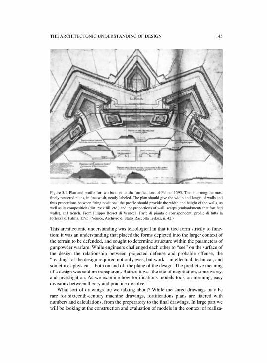
THE ARCHITECTONIC UNDERSTANDING OF DESIGN 145
Figure 5.1. Plan and profile for two bastions at the fortifications of Palma, 1595. This is among the mostfinely rendered plans, in fine wash, neatly labeled. The plan should give the width and length of walls andthus proportions between firing positions; the profile should provide the width and height of the walls, aswell as its composition (dirt, rock fill, etc.) and the proportions of wall, scarps (embankments that fortifiedwalls), and trench. From Filippo Besset di Verneda, Parte di pianta e corrispondenti profile di tutta lafortezza di Palma, 1595. (Venice, Archivio di Stato, Raccolta Terkuz, n. 42.)
This architectonic understanding was teleological in that it tied form strictly to func-tion; it was an understanding that placed the forms depicted into the larger context ofthe terrain to be defended, and sought to determine structure within the parameters ofgunpowder warfare. While engineers challenged each other to “see” on the surface ofthe design the relationship between projected defense and probable offense, the“reading” of the design required not only eyes, but work—intellectual, technical, andsometimes physical—both on and off the plane of the design. The predictive meaningof a design was seldom transparent. Rather, it was the site of negotiation, controversy,and investigation. As we examine how fortifications models took on meaning, easydivisions between theory and practice dissolve.
What sort of drawings are we talking about? While measured drawings may berare for sixteenth-century machine drawings, fortifications plans are littered withnumbers and calculations, from the preparatory to the final drawings. In large part wewill be looking at the construction and evaluation of models in the context of realiza-
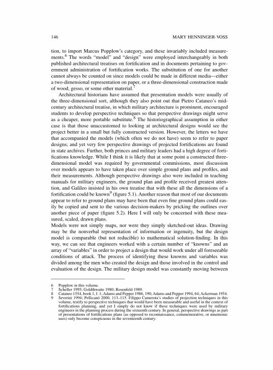
146 MARY HENNINGER-VOSS
tion, to import Marcus Popplow’s category, and these invariably included measure-ments.6 The words “model” and “design” were employed interchangeably in bothpublished architectural treatises on fortification and in documents pertaining to gov-ernment administration of fortification works. The substitution of one for anothercannot always be counted on since models could be made in different media—eithera two-dimensional representation on paper, or a three-dimensional construction madeof wood, gesso, or some other material.7
Architectural historians have assumed that presentation models were usually ofthe three-dimensional sort, although they also point out that Pietro Cataneo’s mid-century architectural treatise, in which military architecture is prominent, encouragedstudents to develop perspective techniques so that perspective drawings might serveas a cheaper, more portable substitute.8 The historiographical assumption in eithercase is that those unaccustomed to looking at architectural designs would see theproject better in a small but fully constructed version. However, the letters we havethat accompanied the models (which often we do not have) seem to refer to paperdesigns; and yet very few perspective drawings of projected fortifications are foundin state archives. Further, both princes and military leaders had a high degree of forti-fications knowledge. While I think it is likely that at some point a constructed three-dimensional model was required by governmental commissions, most discussionover models appears to have taken place over simple ground plans and profiles, andtheir measurements. Although perspective drawings also were included in teachingmanuals for military engineers, the ground plan and profile received greatest atten-tion, and Galileo insisted in his own treatise that with these all the dimensions of afortification could be known9 (figure 5.1). Another reason that most of our documentsappear to refer to ground plans may have been that even fine ground plans could eas-ily be copied and sent to the various decision-makers by pricking the outlines overanother piece of paper (figure 5.2). Here I will only be concerned with these mea-sured, scaled, drawn plans.Models were not simply maps, nor were they simply sketched-out ideas. Drawingmay be the nonverbal representation of information or ingenuity, but the designmodel is comparable (but not reducible) to mathematical solution-finding. In thisway, we can see that engineers worked with a certain number of “knowns” and anarray of “variables” in order to project a design that would work under all foreseeableconditions of attack. The process of identifying these knowns and variables wasdivided among the men who created the design and those involved in the control andevaluation of the design. The military design model was constantly moving between
6 Popplow in this volume. 7 Scheller 1995; Goldthwaite 1980; Rosenfeld 1989.8 Cataneo 1554, book 1, f. 1; Adams and Pepper 1986, 190; Adams and Pepper 1994, 64; Ackerman 1954.9 Severini 1994; Pellicanò 2000, 113–115. Filippo Camerota’s studies of projection techniques in this
volume, testify to perspective techniques that would have been measurable and useful in the context offortifications planning, and yet I simply do not know if these techniques were used by militaryengineers in the planning process during the sixteenth century. In general, perspective drawings as partof presentations of fortifications plans (as opposed to reconnaissance, commemorative, or mnemonicuses) only become conspicuous in the seventeenth century.
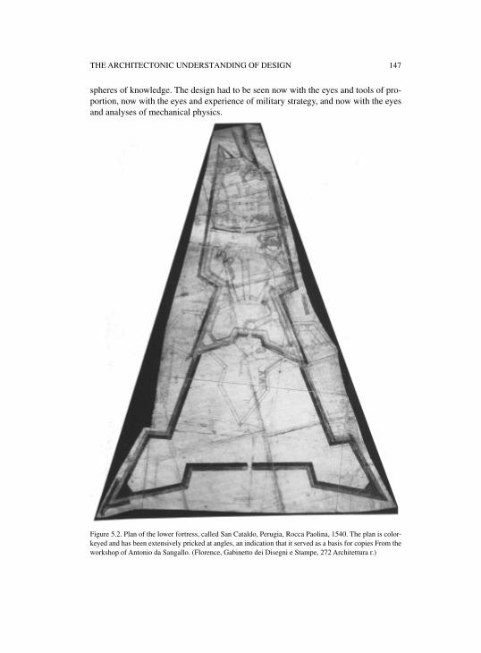
THE ARCHITECTONIC UNDERSTANDING OF DESIGN 147
spheres of knowledge. The design had to be seen now with the eyes and tools of pro-portion, now with the eyes and experience of military strategy, and now with the eyesand analyses of mechanical physics.
Figure 5.2. Plan of the lower fortress, called San Cataldo, Perugia, Rocca Paolina, 1540. The plan is color-keyed and has been extensively pricked at angles, an indication that it served as a basis for copies From theworkshop of Antonio da Sangallo. (Florence, Gabinetto dei Disegni e Stampe, 272 Architettura r.)
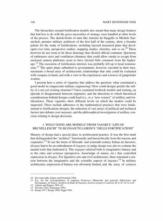
148 MARY HENNINGER-VOSS
The hierarchies around fortification models also meant that many design featuresthat had less to do with the gross necessities of strategy were handled at other levelsof the process. The sketch-books of men like Antonio da Sangallo or Michele San-micheli, premier military architects of the first half of the century, show a broaderpalette for the study of fortifications, including layered measured plans that devel-oped over time, perspective studies, mapping studies, sketches, and so on.10 Thesehowever do not seem to be those drawings that elicited official comment. Questionsof embrasure sizes and ventilation chimneys that could allow smoke to escape fromenclosed cannon platforms seem to have elicited little comment from the higher-ups.11 The execution of fortification interiors was probably left up to head stonema-sons.12 The spare plans submitted to governments, however, encoded in their mea-surements a broad array of architectonic relationships that only could be evaluatedwith compass in hand, and with a view to the experiences and sciences of gunpowderwarfare.
I present here a series of vignettes that address the question: what constituted agood model in cinquecento military engineering? How could designs predict the util-ity of a not yet existing structure? I have examined textbook models and training, anepisode of disagreement between engineers, and the directions to which theoreticalconsiderations behind designs could lead (i.e., to a “new science” of artillery and for-tifications). These vignettes show different levels on which the models could beinspected. These include adherence to the mathematical practices that were funda-mental to fortifications designs; the reduction of vast arrays of political and technicalfactors into debates over measure, and the philosophical investigation of artillery con-cerns relating to design decisions.
1. WHAT GOOD ARE MODELS? FROM VASARI’S “LIFE OF BRUNELLESCHI” TO BUONAIUTO LORINI’S “DELLE FORTIFICATIONI”
Mastery of design had a special place in architectural practice. It was the first markthat distinguished the “architect” functionally and hierarchically from the masons andcarpenters.13 To use the terms of fifteenth- and sixteenth-century Italian art theorists,disegno had to be an embodiment of ingegno; to judge design was also to evaluate themental tools that fashioned it. This ingegno referred both to imaginative fantasy andto the rules and sciences (perspective, knowledge of nature, etc.) that controlledexpression in disegno. For figurative arts and civil architecture, there remained a ten-sion between the imaginative and the scientific aspects of ingegno.14 In militaryarchitecture, expression of fantasy was obviously limited, and the array of sciences
10 See especially Adams and Frommel 1994.11 E.g. see the correspondence of engineer Francesco Malacrede and generals Pallavicino and
Savorgnano, in Venice, Archivio di Stato di Venezia, Archivio proprio Contarini, B. 8, ff. viir to xviir.12 Adams and Pepper 1994, 62. 13 Pevsner 1942; Ackerman 1954. 14 Kemp 1977; Kemp 1990; Puppi 1981.
THE ARCHITECTONIC UNDERSTANDING OF DESIGN 149
Figure 5.3. An ideal circuit of walls. The bastioned curtain wall is surrounded by a star-shaped “coveredway,” and in between the rays of the stars are rivelin outworks, additions popular in the seventeenthcentury. Pianta di Palmanova. (Venice, Biblioteca Museo Correr, Cod. Cic. 3486/IV.)
and practices in which the architect was to be conversant ranged from geometric con-struction to tactical savvy to artillery aim.15
There is a reason why sixteenth-century military architects began to identifythemselves more exclusively as “engineers,” and distance themselves from civilarchitects who dealt in “the secrets of the statue-makers” guild.”16 Military architec-ture was completely reconfigured in the first decades of the sixteenth century. Due tothe demands of mounting and withstanding the new gunpowder weapons, highcrenellated walls and round towers gave way to a polygonal circuit of walls andspade-like bastions (the enceinte known as the trace italienne), and a variety of plat-forms, trenches, outworks, earthworks, countermines, and scarping techniques(figure 5.3). The design of fortifications became more closely associated with thedesign of machines, and engineers began even referring to the fortifications system as“la macchina.” The new fortifications offered little leeway for aesthetic choice oreven traditional knowledge, as the innovative new architecture was to meet therequirements of gunpowder weapons.17 At the same time, military engineers medi-ated between stonemasons (and legions of unskilled laborers), military leaders, and
15 Hale 1977; de la Croix 1963, 30–50; Lamberini 1987 and 1990; Manno 1987; Fiocca, 1998, passim.16 Lorini 1597. See also Hale 1977. I have noticed the same phenomenon in the roles of the Florentine
court where Bernardo Buontalenti and Ammanati are both called “architetto” or “ingegnero” inalternate years.
17 Wilkinson 1988.
150 MARY HENNINGER-VOSS
governmental patrons while their training became ever more associated with mathe-matical arts. Increasingly through the century, fortifications engineers became mem-bers of large teams of professionals, beyond the cooperation and contributions ofworkshop assistants.18 While workshop practices still thrived around figures such asBernardo Buontalenti in Florence and the Genga family in Urbino, military engineersincreasingly made their primary alliances among military leaders who had charge ofengineering.
It was perhaps for these very reasons that the great sixteenth-century proponent ofthe dignity of arts of disegno, Giorgio Vasari, paid relatively little attention to militaryarchitecture. In his Life of Francesco di Giorgio Martini, he even lamented thatFrancesco had become too carried away with military concerns. While Vasari wantedto found design in a “science” that adhered to Aristotelian notions of theoreticalknowledge, he also characterized design as a manifestation of inscrutable genius.Vasari’s Life of Filippo Brunelleschi unwittingly lays out the tension between scien-tific clarity and skillful genius in models made for large public works. The tale is par-adigmatic of many tales told in the history of this field.
In any large-scale building project in which government administration wasinvolved, the model appears as an object that is at once clear and contested. That is,the design might clearly show what is to be constructed, and even how. But the pre-dictive quality, whether the actual structure will “work,” was in question when inno-vation was introduced. This is demonstrated in Vasari’s Life of Brunelleschi. Thestory illustrates the way in which models served as manifestations of the inventive-ness and knowledge of the architect, even as, paradoxically, judgment of them couldbe a problematic issue. According to Vasari, Brunelleschi secretly worked up modelsfor the building of the duomo on the Florentine Cathedral, including detailed studiesof lifting machines and scaffolding and a complete scaled wood model. These he pro-duced at opportune moments. The wardens of the Cathedral, however, remained everhesitant to award complete authority to Filippo, and the models produced by rivalarchitects continually confused them, even as the cupola rose daily under Brunelles-chi’s direction.19
Vasari’s Life of Brunelleschi is a story of heroic ingegno tied to meticulous dis-egno. Brunelleschi’s designs and models are in fact testaments to his ingegno. With-out them, we would not be convinced how much of the construction of the duomo layin the direct control of the architect, and how much was contributed by the masterstonemasons, carpenters, and metal workers on the job. Vasari makes it clear thatevery detail of the construction owes its genesis to a sketch or model from Brunelles-chi’s hand. Or rather from his head, since Vasari emphasizes that the workers were“poor men who worked by their hands,” and that work could not proceed withoutBrunelleschi’s direction. Rather, Brunelleschi taught the artisans everything—he con-stantly made models for the stonecutters and ironworkers, we are told, “from wood,wax, or even turnips.” Control over the models meant control over the project from
18 Lamberini 1986. 19 Vasari 1963.
THE ARCHITECTONIC UNDERSTANDING OF DESIGN 151
top to bottom, and if Vasari could link the design function to high intellectual activity,so much the better.20
Models in Vasari’s story have a transparency of meaning on one level. For exam-ple, Vasari recounts the story in which Brunelleschi refuses to show his designs forputting the cupola on the Cathedral without pillars or other supports during the war-dens’ convocation of architects, since then the other masters too would know how todo it. Within the time frame of the Life, however, models as a class of object appear tohave had a murkier aspect. The model of Brunelleschi’s rival, Lorenzo Ghiberti, wasrewarded with the incredible sum of 300 ducats, but, in Vasari, exhibits little or noth-ing of use. The models of the other masters are imperfect, and only confuse thosewhose “fickleness, ignorance and lack of understanding” led them to favor other con-tenders. But how does one escape such ignorance? How does a warden or patronjudge a model?
Vasari’s story only vaguely accounts for even Brunelleschi’s knowledge—hisyears of study in Rome, where he “drew every sort of building.” However, as Vasarihimself would tell us (and fifteenth-century contemporaries such as Leon BattistaAlberti), Brunelleschi’s architecture of the Florentine Duomo is a signal chapter inthe innovative approaches fifteenth-century architects took in creating a renaissanceworld competitive with the ancient one. It was a feat not only in the management ofgeometrical form, but of the weighty stones that went into its construction.21 Whethersuch knowledge could have been “seen” in Brunelleschi’s models in and of them-selves, as Vasari seems to suggest, is another matter. The Florentine architect’s ownadvice to the “Sienese Archimedes,” the civil and military machine designer MarianoTaccola, suggested only that Taccola should not “squander his talent” explaining hisinventions to ignorant persons who would only keep them from being heard “in highplaces and by the right authority.” Reveal them only to an “appropriate gathering ofmen of science, philosophers, and masters in the mechanical art,” Brunelleschiexhorted.22 This is hardly an exhortation to “craft secrecy” as it has sometimes beeninterpreted, but how such a gathering might be constituted in the fifteenth century,except through the informal coming together of friends, is less clear. An institutionalframework for men learned in design and its sciences was in fact to be part of Vasari’svision in his establishment of Florence’s Accademia del Disegno in 1563.23
20 Obviously the sort of models that Brunelleschi might have made with wood scraps and turnips are notrelated to the sort of scaled drawings we address here. However, it is instructive that Vasari employsthese stories to build up a general profile of Brunelleschi’s design abilities. While Vasari had his ownprofessional motives for presenting Brunelleschi in this light, even in the generation followingBrunelleschi’s death, Tuccio Manetti also heroized Brunelleschi’s models, and his story ofBrunelleschi’s turnips are the source for Vasari, as are many other elements of the account. HowardSaalman’s conservative reading of the documents related to work on the Duomo, however, brings ahealthy skepticism to the view of Brunelleschi’s enormous superiority over other craftsmen builders.See text and notes of Manetti 1970. Both Manetti and Vasari referred to models as a way ofunderscoring Brunelleschi’s authorship of the building and differentiating him from other buildingprofessionals.
21 See Settle 1978. 22 Battisti 1981, 20–21.23 Barzman 1989; Wazbinski 1987; Ward 1972; Kemp 1990, 132–135.
152 MARY HENNINGER-VOSS
The Accademia del Disegno was in fact a kind of quasi-state institution for thetraining and organization of painters, sculptors, and architects—men who soughtrelease from the confines of crafts guilds, and whose distinction was precisely theirknowledge of design. Patronized by the Medici Dukes, the Accademia served as theprimary consulting agency on all engineering projects and public works.24 Officerswere appointed directly by the Duke, and the academy fostered military as well ascivil architects. Vasari’s own nephew, the academician Giorgio Vasari the Younger,collected numerous designs pertaining to military engineering, from various measur-ing instruments to artillery pieces.25 Galileo’s friend and academician, LudovicoCigoli, wrote a treatise on perspective that featured military application in its iconog-raphy, and the illegitimate Medici sons, Don Giovanni and Don Antonio, were asso-ciated with the Accademia del Disegno in part because they were expected to beskilled in military architecture. In 1595, when Don Giovanni was serving EmperorRudolf II in the Hungarian wars, he sent home to Florence for “good engineers andmen of design.”26 Buonaiuto Lorini, a Florentine who later became a senior engineerin the employ of Venice, was also encouraged by the Dukes of Florence to masterdesign and to pursue a military career.
Lorini in fact published a treatise, Delle fortificationi, which outlined the expecta-tions of a good working design. The purpose of the treatise is emphasized through theinclusion of a dialogue between a count delayed at Zara (in Dalmatia) and Lorinihimself. It centers around the problem of determining which plans will succeed, andwhat qualifications of an engineer are requisite. Design, Lorini suggests, is necessaryto all arts, but especially to command.
On disegno depends the true understanding of all things: it enables one to show that greatperfection which the ingengo of a man may have, who both imitates the wonderful worksmade by nature and by art, and also shows everyone, and makes them understand each ofhis concepts. And therefore disegno is of such value that whoever masters it can truly saythat it is very easy to express perfectly any work that he wants to put forth. This isbecause through this [disegno] are shown all inventions and their elements—approvingthe good and emending the poor. But also the sites of the country, that is the land, the sea,and whatever natural and artificial features are at work there, are all represented on asimple piece of paper, whether you make your demonstration as things really are, orshould be. Also, being able to see the design of things would not only be useful, but nec-essary—particularly with regard to explicating and making understood our concepts, asit would be. For example, if you wanted to present and make understood the constructionin a city that has been done, or needs to be done, simply with words, it would turn outimpossible not only to be able to judge its perfections and imperfections, but also toknow its true form. On the other hand in disegno made with measure, one can make thisdemonstrable.27
This lengthy passage exposes much about expectations on models and the work theywere to do. Lorini conceives of disegno as a process, which allows one to represent
24 Ward 1972, 111–116.25 The younger Vasari’s manuscripts are found in the Biblioteca Riccardiana, Florence.26 Florence, Archivio di Stato Firenze, Carte Alessandri: Archivio Privato di D. Giov. De Medici, Filza 8,
f. 47–49.27 Lorini 1597, 32. On Lorini at Zara, see Promis 1874, 640.
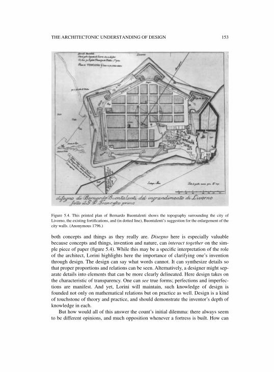
THE ARCHITECTONIC UNDERSTANDING OF DESIGN 153
Figure 5.4. This printed plan of Bernardo Buontalenti shows the topography surrounding the city ofLivorno, the existing fortifications, and (in dotted line), Buontalenti’s suggestion for the enlargement of thecity walls. (Anonymous 1796.)
both concepts and things as they really are. Disegno here is especially valuablebecause concepts and things, invention and nature, can interact together on the sim-ple piece of paper (figure 5.4). While this may be a specific interpretation of the roleof the architect, Lorini highlights here the importance of clarifying one’s inventionthrough design. The design can say what words cannot. It can synthesize details sothat proper proportions and relations can be seen. Alternatively, a designer might sep-arate details into elements that can be more clearly delineated. Here design takes onthe characteristic of transparency. One can see true forms; perfections and imperfec-tions are manifest. And yet, Lorini will maintain, such knowledge of design isfounded not only on mathematical relations but on practice as well. Design is a kindof touchstone of theory and practice, and should demonstrate the inventor’s depth ofknowledge in each.
But how would all of this answer the count’s initial dilemma: there always seemto be different opinions, and much opposition whenever a fortress is built. How can
154 MARY HENNINGER-VOSS
there be any rules for fortification beyond the various opinions of the different inven-tors? Lorini is quick to reply that the engineer, like the physician, relies on both the-ory—(“having its foundation and every perfection from mathematics”)—andpractice.28 But how can evidence of “practice” also be read off the design? Indeed,this is the unvoiced problem that peeks around the confident statements of a greatnumber of military engineering treatises. How is the local, and individual, knowledgeof an engineer’s practical knowledge to be assessed, and how should it enter thedesign process? One answer implicit in Lorini’s treatise is that opinions on fortifica-tions are expressed as design, and there are rules for design, expressed in measure.Measure captures not only the theoretical, mathematical feature Lorini constantlyalludes to, but it often appears in engineering treatises as a kind of boiled-down expe-rience of practice itself. That is, measurement often appears to stand not only for aparticular act of measure, but also for repetitive experience itself.
Lorini’s patron, the fortifications governor and artillery general Giulio Savorg-nano, claimed to have spent his fortune in the service of the Venetian State so that “Ileave nothing but the great quantity of designs and honorable writings that are to mymerit.”29 Indeed one of the most copied of Savorgnano’s writings is a list of rules bywhich design could be judged. When Savorgnano wanted to outline rules for theprinces and counselors who would decide among designs put forth by soldiers, engi-neers, and captains, he warned,
To be able to have a solid judgment on this science [of fortification] is not so easy, nor isit enough to know how to design on paper cortinas and bastions in different ways, sincethere could be proposed many forms and different materials to the Prince who must makethe decision. For this reason, the counselors reason well when they hear one [plan], butthen when they have to compare those that disagree, the counselors that have never beento war remain confused and irresolute.
Savorgnano followed up with 25 rules for the judgment of fortifications. As it turnsout, the guidelines this artillery general and superintendent of fortresses provides toameliorate a lack of battle experience serves itself as a kind of measuring stick to beheld to each proposed design. Almost every one of Savorgnano’s rules is a parameterof measure that must be met. For example, the first rule is that the distance betweenthe flank of one bastion to the outer angle of the next (or the protruding point of thebastion) should be 200 passi so that enemy artillery will not be able to shoot at theinside of the bastion from the point of the counterscarp without facing defensive fire.The second rule defines the flank of a bastion at 30 passi since that is how much roomwould be needed to operate two cannons.30
Experience, like the landscape itself, could be represented in measure. It is in thisway that designs offered to place before one’s eyes what did not yet exist, in relationto both the landscape that did exist and the dictates of experience. Through design, as
28 Ibid., 5429 Venice, Archivio di Stato di Venezia, Mat. Mist. Nob., B. 5, letter dated 15 May, 1592.30 Giulio Savorgnano, “Regule delle fortificatione Moderna di Ill.mo et Ecc.mo Sig.or Giulio
Savorgnano,” Venice, Archivio di Stato di Venezia, Mat. Mist. Nob., B. 13, f. 3r–3v. See also Manno1987.
THE ARCHITECTONIC UNDERSTANDING OF DESIGN 155
Lorini suggested, the experienced engineer could determine the best proportions ofthe parts of a fortification plan, and how it would perform in given situations. But ofcourse the final determination of what plan was “best” did not fall to the militaryarchitect. Models were the centerpiece to a circuit of opinions in which the engineerhad only one voice, and qua engineer (as opposed to as a military officer), not a terri-bly significant voice.31
Models were the first reports sent to senior commanders or engineers, or some-times the only thing they would see before making their own emendations. SoFrancesco Maria della Rovere I, the Duke of Urbino and master architect of the Vene-tian fortification system before his death in 1538, obtained the “models and mea-sures” for fortification at Vicenza from a m[aestro] Agostino so he could prepare togo over the details when he reached Vicenza himself.32 Another fortifications expertin the employ of Venice, Sforza Pallavicino, apparently made a number of sugges-tions on models sent to him for various projects in progress within Venetian territo-ries, sometimes without ever having seen the site at all. He had only the designs torely on.33 This was of course routinely the case for the final decision-makers, espe-cially in the case of Venice. An entire department of government, the provveditori allefortezze, was instituted primarily to look after and track the flow of these models, andrecords relating to their progress.34 Over 40 senators were expected to review themodels of one of Michele Sanmicheli’s contested fortification projects, and presenta-tions were conducted regularly in the Senate.35 Hence Savorgnano’s “rules.”
2. EPISTEMOLOGICAL ANCHORS: CARTOGRAPHIC SURVEY AND GEOMETRIC DESIGN
Measured design was the bond between the experience of the engineer and his pre-tensions to science. It was also the chain of good faith that bound the lieutenants,commanders, junior and senior engineers, and the counsels of government.36 It wasthe means by which decisions that could affect the lives of hundreds of men, or thou-sands of people, could be made at a distance of hundreds of miles. It is not coinciden-tal that military engineers tried to impress on their patrons the epistemologicalfoundation of their practice—not merely for rhetorical effect, but often in conscien-tious earnestness. Fortifications designs were as much a product of human imagina-tion as any other building, but they had to fit both a real present physical reality (theterrain of the place to be fortified) and a future possible reality (the eventuality ofsiege). Military engineers had one oar in cartographic methods, which promised toreduce to scale exactly physical landscapes and standing walls, and another in thegeometric methods, which allowed the design of “perfect” forms of desired propor-
31 Morachiello 1988, 45–47. 32 Promis 1874, 109. 33 Venice, Archivio di Stato di Venezia, Mat. Mist. Nob., B. 7, ff. 10r to 20r.34 J. R. Hale 1983b. 35 Venice, Archivio di Stato di Venezia, Sen. Terr, Reg. 33, ff. 70v–71r and 135v–136r. See also Hale and
Mallet 1984, 250; see Lamberini 1987. 36 Lamberini 1987, 17.
156 MARY HENNINGER-VOSS
tionalities. Textbooks extolled the virtues of these practices, and could also serve as akind of book of models of various structures and techniques that could be adapted toparticular sites.
The method of Sanmicheli is illuminating. A report on work he did for DukeFrancesco Sforza II related,
On arriving, Maestro Michele several times went round the site measuring it, then he gotdown to drawing, first in the form it has now, then, after making a separate sketch show-ing the additions he proposed for making it as strong as possible, he made a further sur-vey to check the levels of the ground with a view to an effectual defense against mines.
Only then did Sanmicheli supply “some finished drawings” to the Duke.37 It appearsoften to have been the case that military engineers drew designs directly on maps ofsurveyed sites. One such production in the Marciana Library shows the outline of theold city walls in pink, the ones recently constructed in green, and the architect’s pro-posed amendments of new bastions and a star-shaped rivelin in yellow.38 The ten-dency could be universalized. “Where steps the military engineer steps thechorographer,” wrote the military engineer Lelio Brancaccio.39 Indeed, survey andmapping techniques had long been important to the architect’s tool box, and was oneof the largest areas of overlap between architects and mathematicians. The practicalmathematical abacco tradition was common training for early modern Italian artifi-cers, and both mathematicians and architects knew survey techniques.40
Measuring instruments, most of which relied on simple triangulation, made mea-suring by sight easily accessible. Most were adaptations of the astrolabe or quadrant,but tracts on measuring instruments multiplied, and these were mostly written by mil-itary engineers, or authors catering to a military audience. There was the vergheastronomiche of the engineer Antonio Lupicini, the mathematician Niccolo Tarta-glia’s instrument in Nova Scientia, Mutio Oddi’s squadra and polimetro, and numer-ous others. Lorini suggested readers turn to one of the compendia of measuringinstruments, Cosimo Bartoli’s Modo di Misurar (figure 5.5).41 Measuring by thischoice of sighting instruments must have been quite a boon to professionals forwhom survey was a vital part of any project, and reconnaissance of enemy strong-holds was a high priority.42
The seriousness with which this task was taken is testified by an episode in thetutelage of Buonaiuto Lorini. Lorini had been sent to Bergamo by his patron GiulioSavorgnano to make some designs of the city. He proved headstrong and “impatient,”as Savorgnano discovered when he reached the city. Lorini had mis-measured a cur-tain wall by 30 passi, and was off on some of his angles by five or six degrees.Employing a particular quadrant, Savorgnano had “busted his brains” to show the
37 Hale 1977, 18.38 Venice, Biblioteca Nazionale Marciana, Ms. Cl. 7, no. 2453 (10493). This appears to be a late
seventeenth-century manuscript detailing information on the fortifications of Venice.39 Lelio Brancacio 1590.40 Rossi 1998; Veltman 1979; Adams 1985. 41 Lupicini 1582; Tartaglia 1537; Oddi 1625 and 1633; Bartoli 1564. 42 See for example Adams et al. 1988.
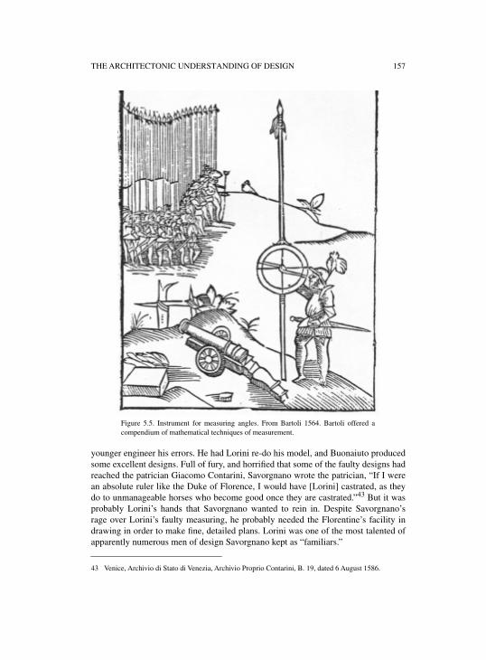
THE ARCHITECTONIC UNDERSTANDING OF DESIGN 157
younger engineer his errors. He had Lorini re-do his model, and Buonaiuto producedsome excellent designs. Full of fury, and horrified that some of the faulty designs hadreached the patrician Giacomo Contarini, Savorgnano wrote the patrician, “If I werean absolute ruler like the Duke of Florence, I would have [Lorini] castrated, as theydo to unmanageable horses who become good once they are castrated.”43 But it wasprobably Lorini’s hands that Savorgnano wanted to rein in. Despite Savorgnano’srage over Lorini’s faulty measuring, he probably needed the Florentine’s facility indrawing in order to make fine, detailed plans. Lorini was one of the most talented ofapparently numerous men of design Savorgnano kept as “familiars.”
43 Venice, Archivio di Stato di Venezia, Archivio Proprio Contarini, B. 19, dated 6 August 1586.
Figure 5.5. Instrument for measuring angles. From Bartoli 1564. Bartoli offered acompendium of mathematical techniques of measurement.
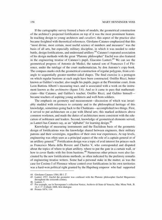
158 MARY HENNINGER-VOSS
If the cartographic survey formed a basis of models, the geometrical constructionof the architect’s projected fortification on top of it was the most prominent feature.In teaching design to young architects and cavalieri, this aspect of the practice alsobecame freighted with theoretical references. Girolamo Cataneo emphasized that this“most divine, most certain, most useful science of numbers and measures” was thebasis of all arts, but especially military discipline, in which it was needed to orderbattle, design fortifications, and understand artillery.44 Cataneo’s repeated associationof his design methods with the great “Platonic philosopher” Euclid was also featuredin the engineering treatise of Cataneo’s pupil, Giacomo Lanteri.45 We can see thegeometrical progress of Antonio de Medici, the natural son of Francesco I of Flo-rence, under the tutelage of the court mathematician, by don Antonio’s copy-book.The compass marks etch the geometrical construction of regular polygons, from a tri-angle to sequentially greater-number-sided shapes. The final exercise is a pentagonon which regular bastions at each angle have been constructed. Ostillio Ricci, betterknown as Galileo’s teacher, also taught his pupils, pages at the Florentine court, fromLeon Battista Alberti’s measuring tract, and is associated with a work on the instru-ment known as the archimetro (figure 5.6). And so it came to pass that mathemati-cians—like Cataneo, and Galileo’s teacher, Ostillio Ricci, and Galileo himself—became teachers of aspiring young architects and well-born soldiers.
The emphasis on geometry and measurement—discussion of which was invari-ably studded with references to certainty and to the philosophical heritage of thisknowledge, sometimes going back to the Chaldeans—accomplished two things. First,it served to put architecture on a par with liberal arts; this marked architects abovecommon workmen, and made the duties of architecture more consistent with the edu-cation of noblemen and leaders. Second, knowledge of geometrical elements served,as Lanteri has Cataneo say, as an “alphabet” for learning design.46
Knowledge of measuring instruments and the Euclidean basis of the geometricdesign of fortifications was the knowledge shared between engineers, their militarypatrons and their sovereigns, regardless of their own war experiences. At top levels,engineering was often seen as a principal aspect of the role of a captain general or ofan artillery general.47 Fortification design was a topic of avid interest for princes suchas Francesco Maria della Rovere and Charles V, who corresponded and disputedabout the topics of where to plant artillery, where to put the gate in a curtain wall, orhow to cover flanks with fire from bastions.48 Numerous other princes were also fas-cinated by the new fortifications methods, as often indicated by the prefatory remarksof engineering treatise writers. Some had a personal stake in the matter, as was thecase for Cosimo I of Florence whose control over fortifications in his own territorieswas a hard-won political right granted by the Hapsburg emperor who had supported
44 Girolamo Cataneo 1584, III f. 2r.45 Lanteri 1557. Euclid the geometer was confused with the Platonic philosopher Euclid Megarensis
throughout the sixteenth century. 46 Lanteri, 7.47 For example, see in Savorgnano’s collection Venice, Archivio di Stato di Venezia, Mat. Miste Nob., B.
14, f. 1v; Collado 1606, first dialogue. 48 Promis 1874, 114
THE ARCHITECTONIC UNDERSTANDING OF DESIGN 159
Figure 5.6. The fortification is reduced exactly to scale. From L’Uso Dell’Archimetro, attributed toOstilio Ricci. (Florence, Biblioteca Nazionale Centrale Firenze, MS Magliabechiana VII 380,f. 118 v; courtesy Ministero per i Beni e le Attività Culturali, all rights reserved.)
160 MARY HENNINGER-VOSS
the Medici rule.49 Others were themselves military figures, as were della Rovere andSforza. Near the end of the sixteenth century, academies for young cavalieri alsomultiplied. The intellectual content of these schools centered around the first sixbooks of Euclid, and a plethora of measuring tracts.50
Geometry gave military architects clarity if not soundness of design. They shareda mode of communication and a lexicon of images. Even in the relatively early trea-tise of the architect Pietro Cataneo (no relation to Girolamo), the fortifications takeon their “orders” from the number of sides of their enceintes. In Cataneo, these arealways depicted as regular polygons.51 In large part, this is because a number of otherdesign choices are predicated on the sides of the enceinte, including the shape of thebastions. Thus the “orders” of fortification came from the number of sides. Even Gio-van Battista Zanchi, the seasoned captain who extolled primarily practice in his trea-tise, followed such an ordering, and suggested that those wanting to learnfortifications spend some time with an “architectural manual of models.”52 Thesewould provide not only schematic geometrical forms, but often perspective drawings“to show all that should be built.” With the proliferation of military engineering man-uals, copy-books incorporated designs from numerous sources.53
However, even the most geometrically-inclined textbook of military architecture(including Lorini’s) would warn its readers that all fortification had to suit the site,and take full account of possible means of offense and defense. Survey and geometri-cal construction were the propaedeutic arts required by anyone who expected to pro-duce or judge fortification designs. They were, of course, insufficient for planningmodels. What mattered was how well adapted to the task the designer had utilizedfortification elements—bastions, cannon platforms, exits, trenches, curtain walls,casemates, covered ways, and more. The heights, wall thickness, bastion angles, dis-tances could all be measured, but had to be measured by knowledge outside design.Nothing shows this so well as the written opinions about these designs.
3. WHAT DESIGNS ARE GOOD ENOUGH? CONTOURS OF CONTROVERSY
Textbooks and mathematicians offered instruction on how the military architectmight achieve clear, measured models. What made the design good and why it wasgood, however, usually needed to be explained. Because the design itself should ide-ally have had a scaled one-to-one correspondence with the landscape, standing struc-tures, and proposed structures, the model could act as a kind of substitute object. Thismeant that other engineers and commanders could assess the relation of the plannedfortification to surrounding landscape features, and that they could in effect mountassaults and defenses on it. That the measurements should stand the test of this sort of
49 Diaz 1976, chap. 2.50 Hale 1983c and 1983d; Torlontano 1998; for contemporary reference see Oddi 1625 and 1633. 51 Pietro Cataneo 1567. 52 Zanchi 1554, 56.53 Oxford, Bodleian Library, Canon Ital. 289, “Regole di Fortificatione” is one such copy-book. It is
comprised almost entirely of designs copied from Lorini, Tensini, Brancaccio, and others.
THE ARCHITECTONIC UNDERSTANDING OF DESIGN 161
analysis shows us that the knowledge embodied in a design was much more extensivethan a simple lexicon of forms. But that knowledge was almost never of a certainnature, despite its expression in the “certain science” of geometry, and thereforedesigns also embodied opinion.
Fortifications textbooks consistently regaled engineers with precepts on how toderive (cavare, literally “to dig out’) the form of a fortification. The form is derivedfrom the landscape; the defense is derived from the offense, the length of wallbetween bastions is derived from the distance artillery shoots; the angle of bastions isderived from the number of sides. That is, nearly every dimension is designed in reac-tion to conditions or factors that may or may not be represented. One had to see notjust a model, but the way walls might hold up to the expected barrage of artillery, andthe maneuvers the design would make possible given various tactics of the enemy.And of course, costs were measured, too. As a whole, the fortifications design had tobe inspected as a machine design might, since the fortress increasingly becamemachine-like in that all elements had to relate to each other for mutual defense.54
Unlike most machine drawings of the sixteenth century, however, fortifications weredrawn to scale, and usually included actual measurements.55 Measurement becamethe terms in which debate could be conducted. All measures—the length of curtains,area of bastions and platforms, depth and width of moats, among many others—alsohad to be related both to environmental factors and to each other, and that is where“seeing” and controversy crossed paths. Here I will look at just one exchange in adebate over the goodness of a design that was a single salvo in a long battle betweenrival fortifications experts.56
After the Venetians lost Cyprus, they were faced with dwindling control over theirAdriatic possessions. The fortification of Corfu and Zara became incendiary topics inthe late 1570s. Corfu was routinely figured as “the principal frontier of our empire aswell as of all Christendom,” and Zara was the Venetians’ chief trading and naval baseon the Dalmatian coast.57 Venice had its top fortifications experts and engineersworking on these projects, and also hired, as many other states often did, an outsideinspector and consultant. Ferrante Vitelli was given leave from his post as Governor-General for the Duke of Savoy to be able to inspect the strategic Venetian sites wherestronger defenses were to be erected, and to review the models for construction.Savorgnano was also involved in the Corfu and Zara projects and sided with the Gov-ernor-General, Sforza Pallavicino, against Vitelli’s opinions. Pallavicino had beeninvolved with the Corfu fortifications early on; he had sent his opinions on a firstphase of fortification there before the fall of Famagosta (1571), and had by 1578made plans for expanded defenses at Zara.58 The two experts’ criticism of each otherwould become bitter and very public. Already in October of 1578, Pallavicino had
54 Hale 1983a; Manno 1987; Wilkinson 1988. 55 See McGee 1999; Poni 1985; Marchis and Dolza 1998. 56 See debate over Palmanova in La Penna 1997.57 Hale and Mallet 1984, 443–444.58 Venice, Archivio di Stato di Venezia, Mat. Miste Nob., B. 7, ff. 18v–20r. For Pallavicino’s career, see
Promis 1874, 447–463; Mallet and Hale 1984, 302–308.
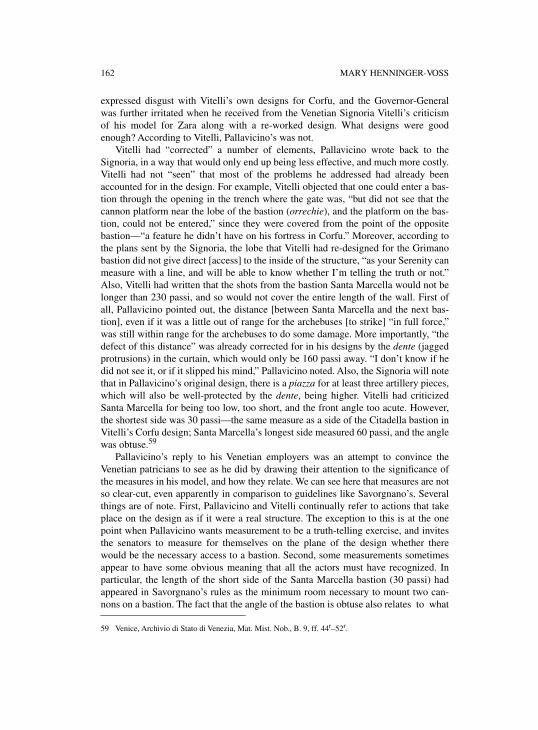
162 MARY HENNINGER-VOSS
expressed disgust with Vitelli’s own designs for Corfu, and the Governor-Generalwas further irritated when he received from the Venetian Signoria Vitelli’s criticismof his model for Zara along with a re-worked design. What designs were goodenough? According to Vitelli, Pallavicino’s was not.
Vitelli had “corrected” a number of elements, Pallavicino wrote back to theSignoria, in a way that would only end up being less effective, and much more costly.Vitelli had not “seen” that most of the problems he addressed had already beenaccounted for in the design. For example, Vitelli objected that one could enter a bas-tion through the opening in the trench where the gate was, “but did not see that thecannon platform near the lobe of the bastion (orrechie), and the platform on the bas-tion, could not be entered,” since they were covered from the point of the oppositebastion—“a feature he didn’t have on his fortress in Corfu.” Moreover, according tothe plans sent by the Signoria, the lobe that Vitelli had re-designed for the Grimanobastion did not give direct [access] to the inside of the structure, “as your Serenity canmeasure with a line, and will be able to know whether I’m telling the truth or not.”Also, Vitelli had written that the shots from the bastion Santa Marcella would not belonger than 230 passi, and so would not cover the entire length of the wall. First ofall, Pallavicino pointed out, the distance [between Santa Marcella and the next bas-tion], even if it was a little out of range for the archebuses [to strike] “in full force,”was still within range for the archebuses to do some damage. More importantly, “thedefect of this distance” was already corrected for in his designs by the dente (jaggedprotrusions) in the curtain, which would only be 160 passi away. “I don’t know if hedid not see it, or if it slipped his mind,” Pallavicino noted. Also, the Signoria will notethat in Pallavicino’s original design, there is a piazza for at least three artillery pieces,which will also be well-protected by the dente, being higher. Vitelli had criticizedSanta Marcella for being too low, too short, and the front angle too acute. However,the shortest side was 30 passi—the same measure as a side of the Citadella bastion inVitelli’s Corfu design; Santa Marcella’s longest side measured 60 passi, and the anglewas obtuse.59
Pallavicino’s reply to his Venetian employers was an attempt to convince theVenetian patricians to see as he did by drawing their attention to the significance ofthe measures in his model, and how they relate. We can see here that measures are notso clear-cut, even apparently in comparison to guidelines like Savorgnano’s. Severalthings are of note. First, Pallavicino and Vitelli continually refer to actions that takeplace on the design as if it were a real structure. The exception to this is at the onepoint when Pallavicino wants measurement to be a truth-telling exercise, and invitesthe senators to measure for themselves on the plane of the design whether therewould be the necessary access to a bastion. Second, some measurements sometimesappear to have some obvious meaning that all the actors must have recognized. Inparticular, the length of the short side of the Santa Marcella bastion (30 passi) hadappeared in Savorgnano’s rules as the minimum room necessary to mount two can-nons on a bastion. The fact that the angle of the bastion is obtuse also relates to what
59 Venice, Archivio di Stato di Venezia, Mat. Mist. Nob., B. 9, ff. 44r–52r.
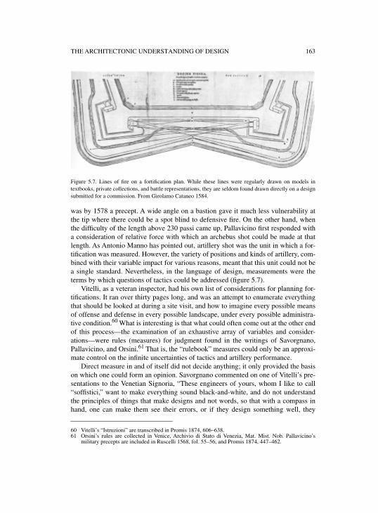
THE ARCHITECTONIC UNDERSTANDING OF DESIGN 163
Figure 5.7. Lines of fire on a fortification plan. While these lines were regularly drawn on models intextbooks, private collections, and battle representations, they are seldom found drawn directly on a designsubmitted for a commission. From Girolamo Cataneo 1584.
was by 1578 a precept. A wide angle on a bastion gave it much less vulnerability atthe tip where there could be a spot blind to defensive fire. On the other hand, whenthe difficulty of the length above 230 passi came up, Pallavicino first responded witha consideration of relative force with which an archebus shot could be made at thatlength. As Antonio Manno has pointed out, artillery shot was the unit in which a for-tification was measured. However, the variety of positions and kinds of artillery, com-bined with their variable impact for various reasons, meant that this unit could not bea single standard. Nevertheless, in the language of design, measurements were theterms by which questions of tactics could be addressed (figure 5.7).
Vitelli, as a veteran inspector, had his own list of considerations for planning for-tifications. It ran over thirty pages long, and was an attempt to enumerate everythingthat should be looked at during a site visit, and how to imagine every possible meansof offense and defense in every possible landscape, under every possible administra-tive condition.60 What is interesting is that what could often come out at the other endof this process—the examination of an exhaustive array of variables and consider-ations—were rules (measures) for judgment found in the writings of Savorgnano,Pallavicino, and Orsini.61 That is, the “rulebook” measures could only be an approxi-mate control on the infinite uncertainties of tactics and artillery performance.
Direct measure in and of itself did not decide anything; it only provided the basison which one could form an opinion. Savorgnano commented on one of Vitelli’s pre-sentations to the Venetian Signoria, “These engineers of yours, whom I like to call“soffistici,” want to make everything sound black-and-white, and do not understandthe principles of things that make designs and not words, so that with a compass inhand, one can make them see their errors, or if they design something well, they
60 Vitelli’s “Istruzioni” are transcribed in Promis 1874, 606–638.61 Orsini’s rules are collected in Venice, Archivio di Stato di Venezia, Mat. Mist. Nob. Pallavicino’s
military precepts are included in Ruscelli 1568, fol. 55–56, and Promis 1874, 447–462.
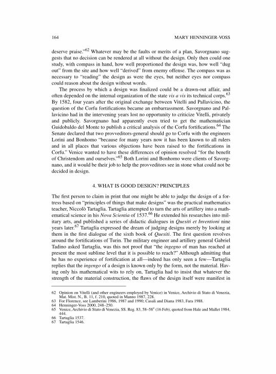
164 MARY HENNINGER-VOSS
deserve praise.”62 Whatever may be the faults or merits of a plan, Savorgnano sug-gests that no decision can be rendered at all without the design. Only then could onestudy, with compass in hand, how well proportioned the design was, how well “dugout” from the site and how well “derived” from enemy offense. The compass was asnecessary to “reading” the design as were the eyes, but neither eyes nor compasscould reason about the design without words.
The process by which a design was finalized could be a drawn-out affair, andoften depended on the internal organization of the state vis a vis its technical corps.63
By 1582, four years after the original exchange between Vitelli and Pallavicino, thequestion of the Corfu fortifications became an embarrassment. Savorgnano and Pal-lavicino had in the intervening years lost no opportunity to criticize Vitelli, privatelyand publicly. Savorgnano had apparently even tried to get the mathematicianGuidobaldo del Monte to publish a critical analysis of the Corfu fortifications.64 TheSenate declared that two provveditors-general should go to Corfu with the engineersLorini and Bonhomo “because for many years now it has been known to all rulersand in all places that various objections have been raised to the fortifications inCorfu.” Venice wanted to have these differences of opinion resolved “for the benefitof Christendom and ourselves.”65 Both Lorini and Bonhomo were clients of Savorg-nano, and it would be their job to help the provveditors see in stone what could not bedecided in design.
4. WHAT IS GOOD DESIGN? PRINCIPLES
The first person to claim in print that one might be able to judge the design of a for-tress based on “principles of things that make designs” was the practical mathematicsteacher, Niccolò Tartaglia. Tartaglia attempted to turn the arts of artillery into a math-ematical science in his Nova Scientia of 1537.66 He extended his researches into mil-itary arts, and published a series of didactic dialogues in Quesiti et Inventioni nineyears later.67 Tartaglia expressed the dream of judging designs merely by looking atthem in the first dialogue of the sixth book of Quesiti. The first question revolvesaround the fortifications of Turin. The military engineer and artillery general GabrielTadino asked Tartaglia, was this not proof that “the ingegno of man has reached atpresent the most sublime level that it is possible to reach?” Although admitting thathe has no experience of fortification at all—indeed has only seen a few—Tartagliareplies that the ingengo of a design is known only by the form, not the material. Hav-ing only his mathematical wits to rely on, Tartaglia had to insist that whatever thestrength of the material construction, the flaws of the design itself were manifest in
62 Opinion on Vitelli (and other engineers employed by Venice) in Venice, Archivio di Stato di Venezia,Mat. Mist. N., B. 11, f. 210, quoted in Manno 1987, 228.
63 For Florence, see Lamberini 1986, 1987 and 1990; Casali and Diana 1983, Fara 1988. 64 Henninger-Voss 2000, 248–250.65 Venice, Archivio di Stato di Venezia, SS. Reg. 83, 58–58v (16 Feb), quoted from Hale and Mallet 1984,
444.66 Tartaglia 1537.67 Tartaglia 1546.
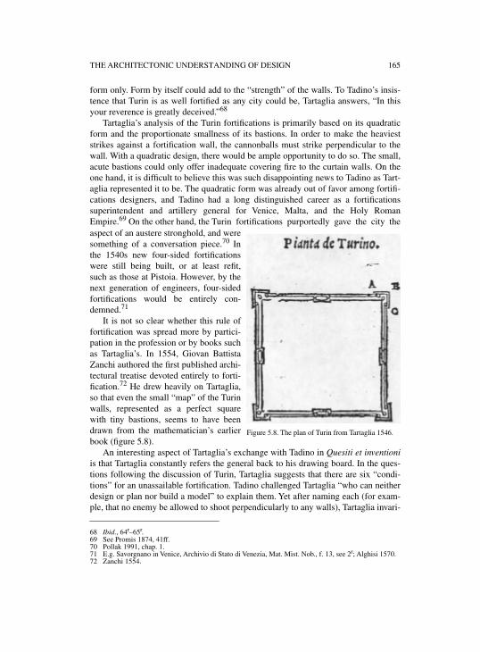
THE ARCHITECTONIC UNDERSTANDING OF DESIGN 165
form only. Form by itself could add to the “strength” of the walls. To Tadino’s insis-tence that Turin is as well fortified as any city could be, Tartaglia answers, “In thisyour reverence is greatly deceived.”68
Tartaglia’s analysis of the Turin fortifications is primarily based on its quadraticform and the proportionate smallness of its bastions. In order to make the heavieststrikes against a fortification wall, the cannonballs must strike perpendicular to thewall. With a quadratic design, there would be ample opportunity to do so. The small,acute bastions could only offer inadequate covering fire to the curtain walls. On theone hand, it is difficult to believe this was such disappointing news to Tadino as Tart-aglia represented it to be. The quadratic form was already out of favor among fortifi-cations designers, and Tadino had a long distinguished career as a fortificationssuperintendent and artillery general for Venice, Malta, and the Holy RomanEmpire.69 On the other hand, the Turin fortifications purportedly gave the city theaspect of an austere stronghold, and weresomething of a conversation piece.70 Inthe 1540s new four-sided fortificationswere still being built, or at least refit,such as those at Pistoia. However, by thenext generation of engineers, four-sidedfortifications would be entirely con-demned.71
It is not so clear whether this rule offortification was spread more by partici-pation in the profession or by books suchas Tartaglia’s. In 1554, Giovan BattistaZanchi authored the first published archi-tectural treatise devoted entirely to forti-fication.72 He drew heavily on Tartaglia,so that even the small “map” of the Turinwalls, represented as a perfect squarewith tiny bastions, seems to have beendrawn from the mathematician’s earlierbook (figure 5.8).
An interesting aspect of Tartaglia’s exchange with Tadino in Quesiti et inventioniis that Tartaglia constantly refers the general back to his drawing board. In the ques-tions following the discussion of Turin, Tartaglia suggests that there are six “condi-tions” for an unassailable fortification. Tadino challenged Tartaglia “who can neitherdesign or plan nor build a model” to explain them. Yet after naming each (for exam-ple, that no enemy be allowed to shoot perpendicularly to any walls), Tartaglia invari-
68 Ibid., 64r–65r.69 See Promis 1874, 41ff.70 Pollak 1991, chap. 1. 71 E.g. Savorgnano in Venice, Archivio di Stato di Venezia, Mat. Mist. Nob., f. 13, see 2r; Alghisi 1570.72 Zanchi 1554.
Figure 5.8. The plan of Turin from Tartaglia 1546.
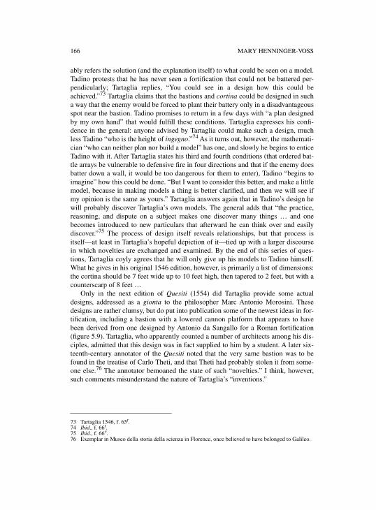
166 MARY HENNINGER-VOSS
ably refers the solution (and the explanation itself) to what could be seen on a model.Tadino protests that he has never seen a fortification that could not be battered per-pendicularly; Tartaglia replies, “You could see in a design how this could beachieved.”73 Tartaglia claims that the bastions and cortina could be designed in sucha way that the enemy would be forced to plant their battery only in a disadvantageousspot near the bastion. Tadino promises to return in a few days with “a plan designedby my own hand” that would fulfill these conditions. Tartaglia expresses his confi-dence in the general: anyone advised by Tartaglia could make such a design, muchless Tadino “who is the height of ingegno.”74 As it turns out, however, the mathemati-cian “who can neither plan nor build a model” has one, and slowly he begins to enticeTadino with it. After Tartaglia states his third and fourth conditions (that ordered bat-tle arrays be vulnerable to defensive fire in four directions and that if the enemy doesbatter down a wall, it would be too dangerous for them to enter), Tadino “begins toimagine” how this could be done. “But I want to consider this better, and make a littlemodel, because in making models a thing is better clarified, and then we will see ifmy opinion is the same as yours.” Tartaglia answers again that in Tadino’s design hewill probably discover Tartaglia’s own models. The general adds that “the practice,reasoning, and dispute on a subject makes one discover many things … and onebecomes introduced to new particulars that afterward he can think over and easilydiscover.”75 The process of design itself reveals relationships, but that process isitself—at least in Tartaglia’s hopeful depiction of it—tied up with a larger discoursein which novelties are exchanged and examined. By the end of this series of ques-tions, Tartaglia coyly agrees that he will only give up his models to Tadino himself.What he gives in his original 1546 edition, however, is primarily a list of dimensions:the cortina should be 7 feet wide up to 10 feet high, then tapered to 2 feet, but with acounterscarp of 8 feet …
Only in the next edition of Quesiti (1554) did Tartaglia provide some actualdesigns, addressed as a gionta to the philosopher Marc Antonio Morosini. Thesedesigns are rather clumsy, but do put into publication some of the newest ideas in for-tification, including a bastion with a lowered cannon platform that appears to havebeen derived from one designed by Antonio da Sangallo for a Roman fortification(figure 5.9). Tartaglia, who apparently counted a number of architects among his dis-ciples, admitted that this design was in fact supplied to him by a student. A later six-teenth-century annotator of the Quesiti noted that the very same bastion was to befound in the treatise of Carlo Theti, and that Theti had probably stolen it from some-one else.76 The annotator bemoaned the state of such “novelties.” I think, however,such comments misunderstand the nature of Tartaglia’s “inventions.”
73 Tartaglia 1546, f. 65r.74 Ibid., f. 66r.75 Ibid., f. 66v.76 Exemplar in Museo della storia della scienza in Florence, once believed to have belonged to Galileo.
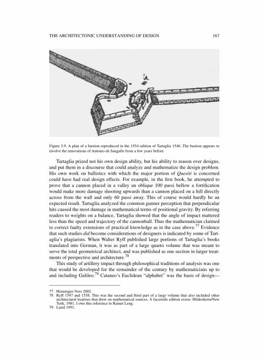
THE ARCHITECTONIC UNDERSTANDING OF DESIGN 167
Figure 5.9. A plan of a bastion reproduced in the 1554 edition of Tartaglia 1546. The bastion appears toinvolve the innovations of Antonio da Sangallo from a few years before.
Tartaglia prized not his own design ability, but his ability to reason over designs,and put them in a discourse that could analyze and mathematize the design problem.His own work on ballistics with which the major portion of Quesiti is concernedcould have had real design effects. For example, in the first book, he attempted toprove that a cannon placed in a valley an oblique 100 passi bellow a fortificationwould make more damage shooting upwards than a cannon placed on a hill directlyacross from the wall and only 60 passi away. This of course would hardly be anexpected result. Tartaglia analyzed the common gunner perception that perpendicularhits caused the most damage in mathematical terms of positional gravity. By referringreaders to weights on a balance, Tartaglia showed that the angle of impact matteredless than the speed and trajectory of the cannonball. Thus the mathematician claimedto correct faulty extensions of practical knowledge as in the case above.77 Evidencethat such studies did become considerations of designers is indicated by some of Tart-aglia’s plagiarists. When Walter Ryff published large portions of Tartaglia’s bookstranslated into German, it was as part of a large quarto volume that was meant toserve the total geometrical architect, and was published as one section in larger treat-ments of perspective and architecture.78
This study of artillery impact through philosophical traditions of analysis was onethat would be developed for the remainder of the century by mathematicians up toand including Galileo.79 Cataneo’s Euclidean “alphabet” was the basis of design—
77 Henninger-Voss 2002.78 Ryff 1547 and 1558. This was the second and third part of a large volume that also included other
architectural treatises that drew on mathematical sources. A facsimile edition exists: Hildesheim/NewYork, 1981. I owe this reference to Rainer Leng.
79 Laird 1991.
168 MARY HENNINGER-VOSS
indeed the opening pages of Lorini’s and Galileo’s fortifications tracts summarizedthe first half book of Euclid—but architectonic thought for fortifications required notonly knowledge of the proportionate relationships that one could see, but also beggedones (like ballistics) that had to be analyzed in separate study.80 It was neverthelessdesign’s foundation in the practical mathematics of design and measure that no doubtgave a practical mathematics teacher like Tartaglia the foothold to present himself asan advisor to a man like Gabriel Tadino, a man so distant in profession and so farTartaglia’s superior in status, experience, and education.
It is impossible to say with any surety what the precise manifestation of these the-oretical excursions on the impact of moving weights could have been on fortificationsdesign. The military architects Francesco de Marchi and Jacopo Fusto Castriotto bothcorresponded with Tartaglia. Castriotto opened his letter floridly praising Tartaglia’singegno in every science, but particularly “artillery and its effect … and the fortifica-tion of cities and castles.” He begged Tartaglia’s opinion on an enclosed design anddiscourse.81
On the other hand, a less impressed Giulio Savorgnano, who had been featured asone of the interlocutors in Quesiti, had his dwarf send Tartaglia some further ques-tions, “to make him figure out some delightful things.”82 The questions are almostentirely questions of what the cause of some effect is, like why the compass does notpoint to true north, or puzzles, like whether a mortar will have a greater effect if it isshot from a height down, or from a low position upwards. They are questions thateither no one knew, or that Savorgnano seems already to have known either from hisown battle experience, or from the vast number of experiments he performed withartillery at his own castle, Osopo. They are challenges to Tartaglia’s claims to dis-cover causes of what is already known by experience, and to be able to know bymathematical analysis what other men find out only through direct experience.
As a way of “ratiocination” that predicted the outcome of experience, Tartaglia’sbooks were useful as teaching aids for readers of little experience, and even as aguide for those who had much. They became standard references for artillery manu-als for another century. Even in eighteenth-century France, Tartaglia’s relativelycrude conceptualization of projectile motion appears to have been employed by com-mon gunners, while Academy-trained artillery officers and designers were trained inthe new rational mechanics that had developed out of the Galilean and Newtonian tra-ditions. And the merits of this mathematical education were still unclear.83 Tartagliahimself would have thought of himself as helping soldiers “understand the principlesof things that make designs.” But it is also clear that Tartaglia wanted to affect theunderstanding of practice not only of men like Gabriel Tadino and Giulio Savorg-
80 For identity of the Lorini–Galileo tracts, see Lamberini 1990. 81 Urbino, Urbino Università, Fondo del Commune, B. 77, fasc. VI, dated 27 Dec. 1549.82 The questions are copied in Venice, Archivio di Stato di Venezia, Mat. Mist. Nob., B. 13, ff. 55v–57v.
They are apparently misdated, however, as 1542, since question 26 (57v) begins “I saw what you saidabout granulated [gun]powder,” a discussion that could not have been “seen” until the Quesiti of 1546.For serious views of the relation between Savorgnano and Tartaglia, see Manno 1987; Ventrice 1998;Keller 1976a.
83 Alder 1997, 93 and passim.
THE ARCHITECTONIC UNDERSTANDING OF DESIGN 169
nano, but also of decision-makers—such as patricians and secretaries to princes—who were constantly called upon to judge design, but who often had no other lenswith which to view them other than the teachings of experts and books.84
***Recent studies of engineering history have focused on the visual basis of the “knowl-edge” of the engineer, and have been skeptical of the contributions “theory” has madeto engineering practices. Eugene Ferguson, for example, specifically relates special-ized training and theoretical argumentation to the engineer’s need to legitimize hisservices before patrons.85 It seems to me, however, that the intervention of practicalmathematicians like Tartaglia was a natural extension of the design practice of archi-tects, which was itself a mathematical practice. Certainly Tartaglia saw this as onepoint of entry for his services. Even if men like Giorgio Vasari had consciouslyattempted to heighten the status of design professionals by uniting them and claiminga theoretical basis for their practice, that practice had for a long time been sophisti-cated geometrically, as Wolfgang Lefèvre and Filippo Camerota have so amplyshown, right down to the art of the stonemason. What changed in sixteenth-centurymilitary architecture was that the design process was shared by a far greater variety ofmen; models were evaluated within a more developed hierarchy (indeed were centralto new bureaucratic agencies); and that the nature of its goals were tied to the concur-rent, but exterior, developments in strategy and artillery. The spheres of knowledgebroadened which, in the terminology of Michael Mahoney, had to be “bootstrapped”in the construction of fortifications. While engineers continued to employ a languageof “seeing” in their opinions on designs, their drawings referred in their measure,execution, and planning to an ever more complex “architectonic” synthesis of geo-metrical techniques, strategic imagination, and newly emerging sciences of weightsin motion.
84 [Henninger-]Voss 1995; Cuomo 1997. 85 Ferguson 1992, 65–73.


PART IVPRODUCING SHAPES

INTRODUCTION TO PART IV
The topic of this section is the origins and development of the geometric techniquesused for drawings and geometrical constructions employed in the process of planningand producing devices or buildings. Thus, it also discusses the origins and develop-ment of such techniques as an integral part and epitome of the professional knowl-edge and skill of engineers and architects.
Early modern depictions of machines, on which most of this volume’s chaptersfocus, do not immediately make accessible the wealth of drawing techniquesemployed by the engineers and architects of the age. Apart from a few orthographicplans of machine parts, since the days of Taccola machines were usually depicted in astyle that looks like a kind of naïve perspective rendering at first glance. No geometryseems to be needed for such creations. On closer inspection, however, it becomesobvious that these depictions not only use deliberately advantages of rendering inperspective, in particular as regards the choice of the viewpoint, but often employ dif-ferent projection techniques such as military perspective. When one starts to payattention to these technical details, these seemingly naïve depictions of machinesappear embedded in the whole range of geometrical projection techniques that werepartly rediscovered, partly reinvented, and in any case autonomously developed andelaborated in the Renaissance—such as perspective projection, orthographic projec-tion, combined views, oblique projection, special projections in the realm of cartog-raphy, and stereometric constructions for special architectural purposes. Taking intoaccount as well that engineering, architecture, and, as figures like Leonardo, Dürer,Raphael, and Michelangelo prove, even fine arts were trades not as secluded in thisage as later, it becomes clear that the different drawing techniques developed in closeconnection. They form a whole of techniques and procedures for the production oftechnical drawings developed by and available to the broad community of engineers,architects, and artists.
The chapter by Filippo Camerota traces in detail the development of the mostimportant methods employed for technical drawings—linear perspective, militaryperspective, shadow projection, double projection, and stereometry. The chapter’semphasis lies on the codification of each of these methods, that is, the codification ofboth a method’s theoretical principles and the procedures and techniques that canlegitimately be applied in its pursuit.
The distinction between drawing methods or styles such as perspective or ortho-graphic projection, on the one hand, and of techniques and procedures through whichthey were realized, on the other, deserves attention. The whole of drawing methodsavailable to engineers, architects, and artists consisted not only of a variety of styles,each of which had different advantages and shortcomings. It also was a many-facetedwhole as regards the techniques and procedures used to achieve a rendering in eachof these styles. To give an example: to trace a true perspective rendering of an object,one can construct it according to the rules of geometry and geometrical optics—ifone has sufficient command of these rules and of the construction techniques requiredby them; if not, one can use mechanical or optical aids and achieve the same result.
174 INTRODUCTION TO PART IV
Techniques and procedures of drawing thus can be distinguished according to theknowledge that they require on the part of the draftsman. It makes sense to speak oflearned drawing techniques in contrast to more practical ones. To a large extent, thisdistinction between learned and practical drawing procedures coincides with thatbetween learned geometry and practitioners’ geometry. In our context, this distinc-tion is of particular significance in two respects—with regard to the roots of the dif-ferent drawing styles and techniques, on the one hand, and, on the other, with regardto the actual employment of these different techniques by engineers, architects, andartists in their professional practice.
The chapter by Wolfgang Lefèvre treats the question of the roots. It studies Anto-nio da Sangallo’s and Albrecht Dürer’s invention of the combined views technique, amethod of plan construction on which modern plan constructions essentially rest, andtraces its learned background as well as its roots in medieval practitioners’ geometry.The chapter by Jeanne Peiffer discusses the practical employment of drawing tech-niques of a learned character. In pursuing the fate of highly developed drawing tech-niques elaborated by Dürer among artists of sixteenth-century Germany, and furtherup to their mathematical codification by Desargues at the beginning of the seven-teenth century, it traces a history of a gradual divorce of learned and practical draw-ing procedures.
6
RENAISSANCE DESCRIPTIVE GEOMETRY:THE CODIFICATION OF DRAWING METHODS
FILIPPO CAMEROTA
The need for drawing as the visual expression of ideas forcefully emerges in the firsttreatises of the Renaissance, particularly in the field of architecture. As Leon BattistaAlberti wrote, “the drawing will be a precise, uniform representation, conceived inthe mind … and brought to completion by a person endowed with ingenuity and cul-ture.”1 It appeared obvious, and not only to a humanist such as Alberti, that drawingwas considered a cultivated language, accessible only to those who knew its basicrules. According to Filarete, “knowing how to read a drawing is more difficult thandrawing,” so that, while there were many “good masters of drawing … if you ask oneaccording to what rule he has drawn a certain building … he will be unable to tellyou.”2 A good architect, then, had to be both “practical and knowledgeable,” in thewords of Francesco di Giorgio;3 that is, he had to possess an adequate dottrina, orknowledge of the disciplines essential to his profession; he had to have ingegno, orinventive talent and the ability to solve technical problems; and he had to know dis-egno, or drawing, in order to correctly represent the product of his ingenuity and toconvey his thought immediately and unequivocally to others. These are the basic pre-mises underlying the extraordinary efforts expended by Renaissance theoreticians tocodify the rules of graphic language that laid the foundations for what, near the endof the eighteenth century, Gaspard Monge was to call “descriptive geometry.”
This work of codifying continued over a rather long span of time and was ofcourse favored by the spread of printing and the rise of the academies. In this chapterthe various stages of codification in writing will be examined in chronological order,grouped under such general headings as painters’ drawings, military engineers’ draw-ings, the projection of shadows, architectural drawings, and those of stonemasons.
In the corpus of Renaissance treatises, the intention of instructing an architect, anengineer, or a “practical and knowledgeable artist” emerges from the structure con-ferred on the development of the themes, which range from elements of practicalgeometry and workshop expedients to geometrical demonstrations based on Euclid’sElements. Considering the great abundance of ingegno in the construction sites andworkshops—as brilliantly demonstrated by works of art and architecture—the theo-reticians’ objective was that of forming a doctrine of drawing that not only wouldserve to refine the techniques of the profession but also, and more importantly, toraise the intellectual status of those whose art was grounded in geometry. This need
1 Alberti 1975, I.1, transl. from Alberti 1988.2 Filarete 1972, 157–158.3 Francesco di Giorgio Martini 1967, VI 489–490.
176 FILIPPO CAMEROTA
was felt not only on the artistic but also on the technological level, where verbaldescriptions of the complicated mechanical devices that drove worksite and warmachines were now intentionally corroborated by the great descriptive value of draw-ings. This significant change with respect to medieval tradition is well documented inthe manuscripts of Mariano di Jacopo, known as Taccola, and Francesco di Giorgio,where a progressive perfecting of techniques of representation may be noted,undoubtedly favored by the progress then being achieved in the field of pictorial per-spective.4 Francesco di Giorgio’s appeal to the need for drawing as the visual expres-sion of ingenuity is echoed by the even stronger admonition of Leonardo, who in oneof the Windsor folios points out the inadequacy of words to describe the works pro-duced by man: “But let me remind you that you should not stammer with words …since you will be greatly surpassed by the work of the painter.”5
1. PAINTER’S GEOMETRY: THE DEVELOPMENT OF LINEAR PERSPECTIVE
The first attempt to establish rules and principles for geometric drawing was made byLeon Battista Alberti, who between 1435 and 1436 composed two works, closelylinked and addressed primarily to painters: Elementa picturae and De pictura.6 Thetitle of the first book explicitly recalls the important treatise by Euclid, which hadbeen the chief reference point for the mathematical sciences since the Middle Ages.Euclid’s Elementa was a fundamentally important text in both the universities, whereit furnished the geometric basis for studies on optics, astronomy and the other arts ofthe quadrivio, and in the abacus schools, where practical mathematics was taught toyouths who were to go on to commerce and the crafts. During the fourteenth centurythe abacus schools underwent notable development, especially in Florence, andamong the pupils were youths destined to become architects, painters, goldsmiths orsculptors. Filippo Brunelleschi, for instance, was one of them.7 In composing his“Euclid for painters,” Alberti thus addressed himself to a public already familiar tosome extent with the principles of practical geometry. His indications serve to con-struct, by relatively simple steps, plane figures both in their true shape and dimin-ished through perspective. It was only the humanist presumption of being able toexplain the problems of drawing without drawings that kept these instructions frombeing immediately comprehensible. In this sense Alberti could be one of those “mostworthy authors” mentioned by Francesco di Giorgio who, having chosen to explaintheir concepts “with characters and letters … and not by figured drawing,” had madethe content of their works obscure to many, being “rare those readers who, not seeingthe drawing, can understand it.”8 In spite of its lack of drawings, Elementa picturae
4 See McGee and Long in this volume. On problems of representation in the treatises of Taccola andFrancesco di Giorgio, see also Galluzzi 1996b, 24ff.; and Lamberini 2001, 3–10.
5 See Francesco di Giorgio Martini 1967, VI 489–490; and Leonardo, Windsor, Royal Library, K/P 162r
(the passage is quoted in Galluzzi 1996b, 84).6 Elementa picturae: see Alberti 1973, III 112–129; and Gambuti 1972, 131–172. De pictura: see Alberti
1973, III. For an English-language edition, see Alberti 1972.7 See Manetti 1976, 52. On abacus schools, see Van Egmond 1980; and Franci and Toti Rigatelli 1989.8 Francesco di Giorgio Martini 1967, VI 489–490.
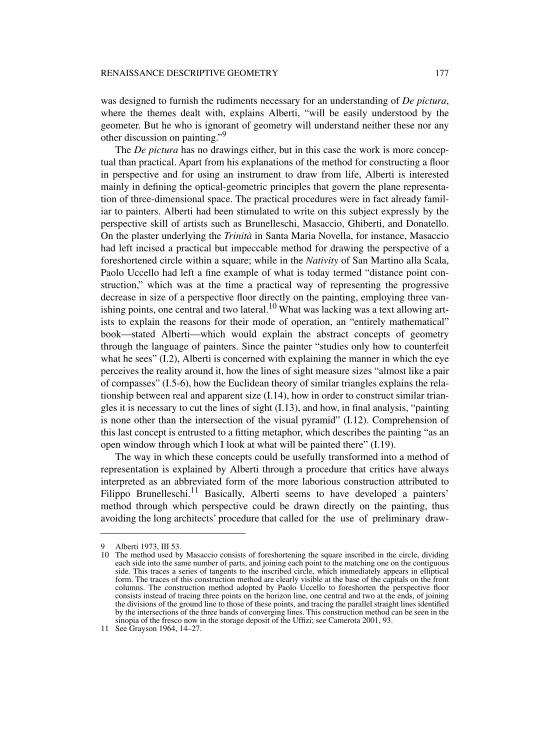
RENAISSANCE DESCRIPTIVE GEOMETRY 177
was designed to furnish the rudiments necessary for an understanding of De pictura,where the themes dealt with, explains Alberti, “will be easily understood by thegeometer. But he who is ignorant of geometry will understand neither these nor anyother discussion on painting.”9
The De pictura has no drawings either, but in this case the work is more concep-tual than practical. Apart from his explanations of the method for constructing a floorin perspective and for using an instrument to draw from life, Alberti is interestedmainly in defining the optical-geometric principles that govern the plane representa-tion of three-dimensional space. The practical procedures were in fact already famil-iar to painters. Alberti had been stimulated to write on this subject expressly by theperspective skill of artists such as Brunelleschi, Masaccio, Ghiberti, and Donatello.On the plaster underlying the Trinità in Santa Maria Novella, for instance, Masacciohad left incised a practical but impeccable method for drawing the perspective of aforeshortened circle within a square; while in the Nativity of San Martino alla Scala,Paolo Uccello had left a fine example of what is today termed “distance point con-struction,” which was at the time a practical way of representing the progressivedecrease in size of a perspective floor directly on the painting, employing three van-ishing points, one central and two lateral.10 What was lacking was a text allowing art-ists to explain the reasons for their mode of operation, an “entirely mathematical”book—stated Alberti—which would explain the abstract concepts of geometrythrough the language of painters. Since the painter “studies only how to counterfeitwhat he sees” (I.2), Alberti is concerned with explaining the manner in which the eyeperceives the reality around it, how the lines of sight measure sizes “almost like a pairof compasses” (I.5-6), how the Euclidean theory of similar triangles explains the rela-tionship between real and apparent size (I.14), how in order to construct similar trian-gles it is necessary to cut the lines of sight (I.13), and how, in final analysis, “paintingis none other than the intersection of the visual pyramid” (I.12). Comprehension ofthis last concept is entrusted to a fitting metaphor, which describes the painting “as anopen window through which I look at what will be painted there” (I.19).
The way in which these concepts could be usefully transformed into a method ofrepresentation is explained by Alberti through a procedure that critics have alwaysinterpreted as an abbreviated form of the more laborious construction attributed toFilippo Brunelleschi.11 Basically, Alberti seems to have developed a painters’method through which perspective could be drawn directly on the painting, thusavoiding the long architects’ procedure that called for the use of preliminary draw-
9 Alberti 1973, III 53.10 The method used by Masaccio consists of foreshortening the square inscribed in the circle, dividing
each side into the same number of parts, and joining each point to the matching one on the contiguousside. This traces a series of tangents to the inscribed circle, which immediately appears in ellipticalform. The traces of this construction method are clearly visible at the base of the capitals on the frontcolumns. The construction method adopted by Paolo Uccello to foreshorten the perspective floorconsists instead of tracing three points on the horizon line, one central and two at the ends, of joiningthe divisions of the ground line to those of these points, and tracing the parallel straight lines identifiedby the intersections of the three bands of converging lines. This construction method can be seen in thesinopia of the fresco now in the storage deposit of the Uffizi; see Camerota 2001, 93.
11 See Grayson 1964, 14–27.

178 FILIPPO CAMEROTA
ings in plan and elevation. With Alberti’s method, the principle of intersection of thevisual pyramid could be applied to the construction of the flooring alone, which,being conceived as a modular grid, furnished the measurements for all of the objectsappearing within the depth of the perspective field; the sinopia of Paolo Uccello’sNatività shows how this was a real pictorial requisite (figure 6.1). Piero dellaFrancesca developed this construction method still further, teaching artists to trans-pose points from the plan to perspective utilizing only the central vanishing point anda diagonal line.12 The three points used by Paolo Uccello were to find a sort of codifi-cation in the work of Jean Pelerin le Viator, who in the first illustrated printed bookon perspective (1505) described the methodical use of the so-called “tiers points,”two lateral points similar to those used in architecture to draw the curve of a pointedarch.13 The “third point” was not to be more appropriately termed the “distancepoint” until the writings of the great codifiers of the sixteenth century: Albrecht
12 Piero della Francesca 1984, I.28–29.13 Viator 1505, in Ivins 1973. In the work of Viator “tiers points” are often used to construct buildings or
interiors in an angular view. The term “tiers point” also appears in the notebook of Villard deHonnecourt (see Hahnloser 1972, 115–116) and is used to indicate the center of the compass in drawinga pointed arch. To trace this type of arch, the architect first draws the springing line, then points thecompass at each end of the line, with the opening equal to the length of the line, and traces two arcs ofa circle which intersect on the central axis. The “third points,” i.e. the centers of the compass at the endsof the line, are also the points of convergence of the joint lines between the stone or brick ashlars ofwhich the arch is built.
Figure 6.1. Perspective scheme constituting the sinopia of Paolo Uccello’s Natività. (The fresco andits sinopia are now in the Uffizi Gallery, Florence.)
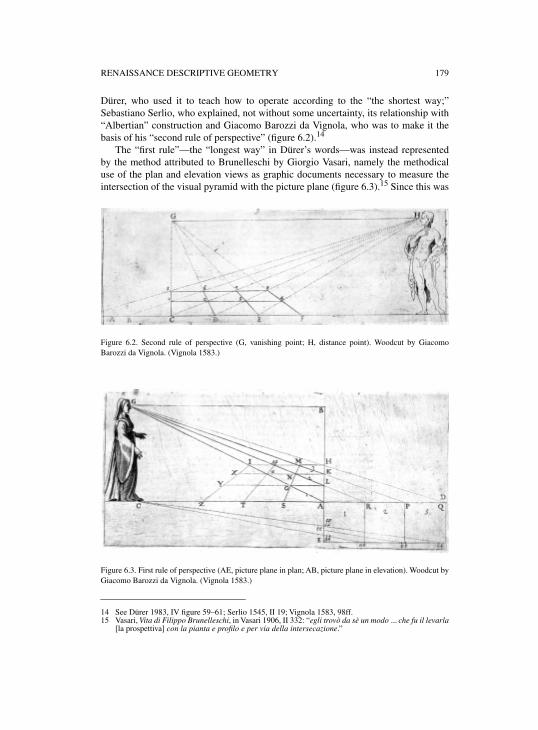
RENAISSANCE DESCRIPTIVE GEOMETRY 179
Dürer, who used it to teach how to operate according to the “the shortest way;”Sebastiano Serlio, who explained, not without some uncertainty, its relationship with“Albertian” construction and Giacomo Barozzi da Vignola, who was to make it thebasis of his “second rule of perspective” (figure 6.2).14
The “first rule”—the “longest way” in Dürer’s words—was instead representedby the method attributed to Brunelleschi by Giorgio Vasari, namely the methodicaluse of the plan and elevation views as graphic documents necessary to measure theintersection of the visual pyramid with the picture plane (figure 6.3).15 Since this was
Figure 6.2. Second rule of perspective (G, vanishing point; H, distance point). Woodcut by GiacomoBarozzi da Vignola. (Vignola 1583.)
Figure 6.3. First rule of perspective (AE, picture plane in plan; AB, picture plane in elevation). Woodcut byGiacomo Barozzi da Vignola. (Vignola 1583.)
14 See Dürer 1983, IV figure 59–61; Serlio 1545, II 19; Vignola 1583, 98ff.15 Vasari, Vita di Filippo Brunelleschi, in Vasari 1906, II 332: “egli trovò da sè un modo ... che fu il levarla
[la prospettiva] con la pianta e profilo e per via della intersecazione.”
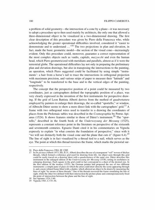
180 FILIPPO CAMEROTA
a problem of solid geometry—the intersection of a cone by a plane—it was necessaryto adopt a procedure up to then used mainly by architects, the only one that allowed athree-dimensional object to be visualized in a two-dimensional drawing. The firstclear description of this procedure was given by Piero della Francesca who, whileacknowledging the greater operational difficulties involved, considered it “easier todemonstrate and to understand …”16 The two projections in plan and elevation, infact, made the basic geometric model—the section of the visual cone—increasinglyevident. Only this procedure could, moreover, guarantee a correct representation ofthe most complex objects such as vaults, capitals, mazzocchi and even the humanhead, which Piero geometricized with meridians and parallels, almost as if it were theterrestrial globe. The operational difficulties lay not only in preparing the preliminaryplan and elevation drawings, but also in transposing the intersections to the painting,an operation, which Piero suggested could be facilitated by using simple “instru-ments’: a hair from a horse’s tail to trace the intersections in orthogonal projectionwith maximum precision, and various strips of paper to measure their “latitude” and“longitude” to be transferred to the base and to the vertical edges of the painting,respectively.
The concept that the perspective position of a point could be measured by twocoordinates, just as cartographers defined the topographic position of a place, wasvery clearly expressed in the invention of the first instruments for perspective draw-ing. If the grid of Leon Battista Alberti derives from the method of quadrettaturaemployed by painters to enlarge their drawings, the so-called “sportello,” or window,of Albrecht Dürer seems to show a more direct link with the cartographers’ grid.17 Aframe with two orthogonal wires used to transfer to a drawing the coordinates ofplaces from the Ptolemaic tables was described in the Cosmographia by Petrus Api-anus (1524). It shows features similar to those of Dürer’s instrument.18 The “spor-tello,” described in the fourth book of the Underweysung der Messung (1525),represents a constant reference point in the literature on perspective of the sixteenthand seventeenth centuries. Egnazio Danti cited it in his commentaries on Vignolaexpressly to explain “in what consists the foundation of perspective,” since with it“we will see distinctly both the visual cone and the plane that cuts it” (figure 6.4).19
The line of sight is in fact visualized by a thread tied to a nail, which serves as theeye. The point at which this thread traverses the frame, which marks the pictorial sur-
16 Piero della Francesca 1984, III 128ff.17 In De pictura (Alberti 1973, III), II.31, Alberti describes the use of a transparent “veil” woven of thicker
threads, which formed a reference grid used for drawing from life. An object seen through this gridcould be easily traced on a drawing sheet with a quadrettatura of the same size. Dürer describes thisinstrument in the enlarged edition of the Underweysung der Messung (1538), noting its usefulness inenlarging drawings. Each square in the grid could in fact correspond to a sheet of the desired size. Inthe first edition of the treatise (1525), the German painter had proposed the use of two differentinstruments: a simple pane of glass on which the artist could draw directly the scene appearing throughit, and a more refined frame fitted with a shutter, which allowed an object to be drawn by measuring thelines of sight “by means of three threads.” One of the threads traversed the frame simulating the line ofsight, while the other two defined with their intersection the picture plane and contemporaneously fixedthe point of intersection between the plane and the line of sight.
18 See Apianus 1524, I 60.19 Vignola 1583, I.3 55–56.
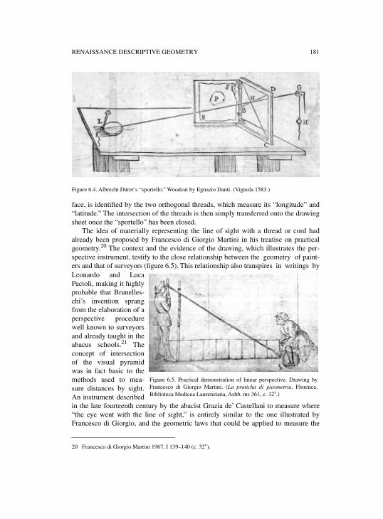
RENAISSANCE DESCRIPTIVE GEOMETRY 181
Figure 6.4. Albrecht Dürer’s “sportello.” Woodcut by Egnazio Danti. (Vignola 1583.)
face, is identified by the two orthogonal threads, which measure its “longitude” and“latitude.” The intersection of the threads is then simply transferred onto the drawingsheet once the “sportello” has been closed.
The idea of materially representing the line of sight with a thread or cord hadalready been proposed by Francesco di Giorgio Martini in his treatise on practicalgeometry.20 The context and the evidence of the drawing, which illustrates the per-spective instrument, testify to the close relationship between the geometry of paint-ers and that of surveyors (figure 6.5). This relationship also transpires in writings byLeonardo and LucaPacioli, making it highlyprobable that Brunelles-chi’s invention sprangfrom the elaboration of aperspective procedurewell known to surveyorsand already taught in theabacus schools.21 Theconcept of intersectionof the visual pyramidwas in fact basic to themethods used to mea-sure distances by sight.An instrument describedin the late fourteenth century by the abacist Grazia de’ Castellani to measure where“the eye went with the line of sight,” is entirely similar to the one illustrated byFrancesco di Giorgio, and the geometric laws that could be applied to measure the
20 Francesco di Giorgio Martini 1967, I 139–140 (c. 32v).
Figure 6.5. Practical demonstration of linear perspective. Drawing byFrancesco di Giorgio Martini. (La praticha di gieometria, Florence,Biblioteca Medicea Laurenziana, Ashb. ms 361, c. 32v.)
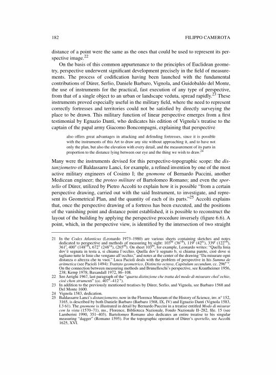
182 FILIPPO CAMEROTA
distance of a point were the same as the ones that could be used to represent its per-spective image.22
On the basis of this common appurtenance to the principles of Euclidean geome-try, perspective underwent significant development precisely in the field of measure-ments. The process of codification having been launched with the fundamentalcontributions of Dürer, Serlio, Daniele Barbaro, Vignola, and Guidobaldo del Monte,the use of instruments for the practical, fast execution of any type of perspective,from that of a single object to an urban or landscape veduta, spread rapidly.23 Theseinstruments proved especially useful in the military field, where the need to representcorrectly fortresses and territories could not be satisfied by directly surveying theplace to be drawn. This military function of linear perspective emerges from a firsttestimonial by Egnazio Danti, who dedicates his edition of Vignola’s treatise to thecaptain of the papal army Giacomo Boncompagni, explaining that perspective
also offers great advantages in attacking and defending fortresses, since it is possiblewith the instruments of this Art to draw any site without approaching it, and to have notonly the plan, but also the elevation with every detail, and the measurement of its parts inproportion to the distance lying between our eye and the thing we wish to draw.24
Many were the instruments devised for this perspective-topographic scope: the dis-tanziometro of Baldassarre Lanci, for example, a refined invention by one of the mostactive military engineers of Cosimo I; the gnomone of Bernardo Puccini, anotherMedicean engineer; the proteo militare of Bartolomeo Romano; and even the spor-tello of Dürer, utilized by Pietro Accolti to explain how it is possible “from a certainperspective drawing, carried out with the said Instrument, to investigate, and repre-sent its Geometrical Plan, and the quantity of each of its parts.”25 Accolti explainsthat, once the perspective drawing of a fortress has been executed, and the positionsof the vanishing point and distance point established, it is possible to reconstruct thelayout of the building by applying the perspective procedure inversely (figure 6.6). Apoint, which, in the perspective view, is identified by the intersection of two straight
21 In the Codex Atlanticus (Leonardo 1973–1980) are various sheets containing sketches and notesdedicated to perspective and methods of measuring by sight: 103br (36vb), 119r (42rc), 339r (122vb),361r, 400v (148vb), 672v (248va), (265rb). On sheet 103br, for example, Leonardo writes: “Quella liniadov’è segnata in testa a, si chiama l’occhio. Quella dov’è segnato b, si chiama parete, cioè dove sitagliano tutte le linie che vengano all’occhio,” and notes at the center of the drawing “Da misurare ognidistanza o altezza che tu vuoi.” Luca Pacioli deals with the problem of perspective in his Summa dearitmetica (see Pacioli 1494): Trattato geometrico, Distinctio octava, Capitulum secundum, cc. 296r–v.On the connection between measuring methods and Brunelleschi’s perspective, see Krautheimer 1956,238; Kemp 1978; Baxandall 1972, 86–108.
22 See Arrighi 1967, last paragraph of the “quarta distinzione che tratta del modo di misurare chol’ochio,cioè chon strumenti” (cc. 407v–412 v).
23 In addition to the previously mentioned treatises by Dürer, Serlio, and Vignola, see Barbaro 1568 andDel Monte 1600.
24 Vignola 1583, dedication.25 Baldassarre Lanci’s distanziometro, now in the Florence Museum of the History of Science, inv. n° 152,
3165, is described by both Daniele Barbaro (Barbaro 1568, IX, IV) and Egnazio Danti (Vignola 1583,I.3 61). The gnomone is illustrated in detail by Bernardo Puccini in a treatise entitled Modo di misurarcon la vista (1570–71), ms., Florence, Biblioteca Nazionale, Fondo Nazionale II–282, file. 15 (seeLamberini 1990, 351–403). Bartolomeo Romano also dedicates an entire treatise to his singularmeasuring “dagger” (Romano 1595). For the topographic operation of Dürer’s sportello, see Accolti1625, XVI.

RENAISSANCE DESCRIPTIVE GEOMETRY 183
lines, converging at the vanishing point and at the distance point respectively, will beidentified in the plan by the intersection of a straight line perpendicular to the pictureplane and one oriented at 45°. This procedure is a precursor of today’s photogramme-try, conferring on perspective a leading role even among the most refined measure-ment methods of the Renaissance.
Figure 6.6. Method for working out the plan of a fortress from its perspective drawing. Woodcut by PietroAccolti. (Accolti 1625.)
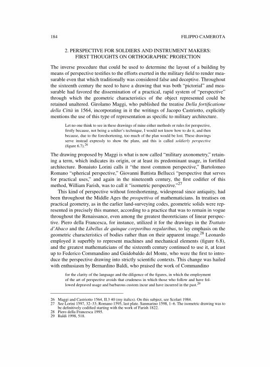
184 FILIPPO CAMEROTA
2. PERSPECTIVE FOR SOLDIERS AND INSTRUMENT MAKERS: FIRST THOUGHTS ON ORTHOGRAPHIC PROJECTION
The inverse procedure that could be used to determine the layout of a building bymeans of perspective testifies to the efforts exerted in the military field to render mea-surable even that which traditionally was considered false and deceptive. Throughoutthe sixteenth century the need to have a drawing that was both “pictorial” and mea-surable had favored the dissemination of a practical, rapid system of “perspective”through which the geometric characteristics of the object represented could beretained unaltered. Girolamo Maggi, who published the treatise Della fortificationedella Città in 1564, incorporating in it the writings of Jacopo Castriotto, explicitlymentions the use of this type of representation as specific to military architecture.
Let no one think to see in these drawings of mine either methods or rules for perspective,firstly because, not being a soldier’s technique, I would not know how to do it, and thenbecause, due to the foreshortening, too much of the plan would be lost. These drawingsserve instead expressly to show the plans, and this is called soldierly perspective(figure 6.7).26
The drawing proposed by Maggi is what is now called “military axonometry,” retain-ing a term, which indicates its origin, or at least its predominant usage, in fortifiedarchitecture. Bonaiuto Lorini calls it “the most common perspective,” BartolomeoRomano “spherical perspective,” Giovanni Battista Bellucci “perspective that servesfor practical uses,” and again in the nineteenth century, the first codifier of thismethod, William Farish, was to call it “isometric perspective.”27
This kind of perspective without foreshortening, widespread since antiquity, hadbeen throughout the Middle Ages the prospettiva of mathematicians. In treatises onpractical geometry, as in the earlier land-surveying codes, geometric solids were rep-resented in precisely this manner, according to a practice that was to remain in voguethroughout the Renaissance, even among the greatest theoreticians of linear perspec-tive. Piero della Francesca, for instance, utilized it for the drawings in the Trattatod’Abaco and the Libellus de quinque corporibus regularibus, to lay emphasis on thegeometric characteristics of bodies rather than on their apparent image.28 Leonardoemployed it superbly to represent machines and mechanical elements (figure 6.8),and the greatest mathematicians of the sixteenth century continued to use it, at leastup to Federico Commandino and Guidobaldo del Monte, who were the first to intro-duce the perspective drawing into strictly scientific contexts. This change was hailedwith enthusiasm by Bernardino Baldi, who praised the work of Commandino
for the clarity of the language and the diligence of the figures, in which the employmentof the art of perspective avoids that crudeness in which those who follow and have fol-lowed depraved usage and barbarous custom incur and have incurred in the past.29
26 Maggi and Castriotto 1564, II.3 40 (my italics). On this subject, see Scolari 1984.27 See Lorini 1597, 32–33; Romano 1595, last plate. Sanmarino 1598, 1–6. The isometric drawing was to
be definitively codified starting with the work of Farish 1822.28 Piero della Francesca 1995.29 Baldi 1998, 518.
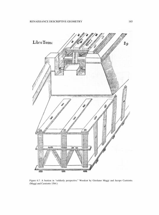
RENAISSANCE DESCRIPTIVE GEOMETRY 185
Figure 6.7. A bastion in “soldierly perspective.” Woodcut by Girolamo Maggi and Jacopo Castriotto.(Maggi and Castriotto 1564.)
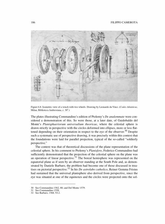
186 FILIPPO CAMEROTA
Figure 6.8. Isometric view of a winch with two wheels. Drawing by Leonardo da Vinci. (Codex Atlanticus,Milan, Biblioteca Ambrosiana, c. 30v.)
The plates illustrating Commandino’s edition of Ptolemy’s De analemmate were con-sidered a demonstration of this. So were those, at a later date, of Guidobaldo delMonte’s Planisphaeriorum universalium theoricae, where the celestial sphere isdrawn strictly in perspective with the circles deformed into ellipses, more or less flat-tened depending on their orientation in respect to the eye of the observer.30 Despitesuch a systematic use of perspective drawing, it was precisely within this context thatthe foundations were laid for parallel projection, typical of the so-called “soldierlyperspective.”
The context was that of theoretical discussions of the plane representation of thecelestial sphere. In his comment to Ptolemy’s Planisfero, Federico Commandino hadsufficiently demonstrated that the projection of the celestial sphere on the plane wasan operation of linear perspective.31 The boreal hemisphere was represented on theequatorial plane as if seen by an observer standing at the South Pole and, as demon-strated by Daniele Barbaro, the problem had become one of those discussed in trea-tises on pictorial perspective.32 In his De astrolabo catholico, Reiner Gemma Frisiushad sustained that the universal planisphere also derived from perspective, since theeye was situated at one of the equinoxes and the circles were projected onto the sol-
30 See Commandino 1562, 80; and Del Monte 1579.31 See Commandino 1558.32 See Barbaro, 1568, VI.2.
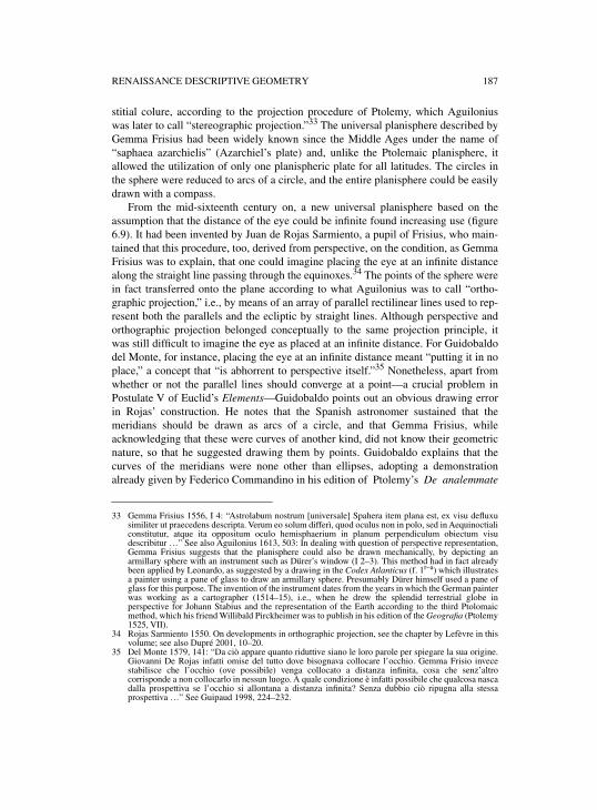
RENAISSANCE DESCRIPTIVE GEOMETRY 187
stitial colure, according to the projection procedure of Ptolemy, which Aguiloniuswas later to call “stereographic projection.”33 The universal planisphere described byGemma Frisius had been widely known since the Middle Ages under the name of“saphaea azarchielis” (Azarchiel’s plate) and, unlike the Ptolemaic planisphere, itallowed the utilization of only one planispheric plate for all latitudes. The circles inthe sphere were reduced to arcs of a circle, and the entire planisphere could be easilydrawn with a compass.
From the mid-sixteenth century on, a new universal planisphere based on theassumption that the distance of the eye could be infinite found increasing use (figure6.9). It had been invented by Juan de Rojas Sarmiento, a pupil of Frisius, who main-tained that this procedure, too, derived from perspective, on the condition, as GemmaFrisius was to explain, that one could imagine placing the eye at an infinite distancealong the straight line passing through the equinoxes.34 The points of the sphere werein fact transferred onto the plane according to what Aguilonius was to call “ortho-graphic projection,” i.e., by means of an array of parallel rectilinear lines used to rep-resent both the parallels and the ecliptic by straight lines. Although perspective andorthographic projection belonged conceptually to the same projection principle, itwas still difficult to imagine the eye as placed at an infinite distance. For Guidobaldodel Monte, for instance, placing the eye at an infinite distance meant “putting it in noplace,” a concept that “is abhorrent to perspective itself.”35 Nonetheless, apart fromwhether or not the parallel lines should converge at a point—a crucial problem inPostulate V of Euclid’s Elements—Guidobaldo points out an obvious drawing errorin Rojas’ construction. He notes that the Spanish astronomer sustained that themeridians should be drawn as arcs of a circle, and that Gemma Frisius, whileacknowledging that these were curves of another kind, did not know their geometricnature, so that he suggested drawing them by points. Guidobaldo explains that thecurves of the meridians were none other than ellipses, adopting a demonstrationalready given by Federico Commandino in his edition of Ptolemy’s De analemmate
33 Gemma Frisius 1556, I 4: “Astrolabum nostrum [universale] Spahera item plana est, ex visu defluxusimiliter ut praecedens descripta. Verum eo solum differì, quod oculus non in polo, sed in Aequinoctialiconstitutur, atque ita oppositum oculo hemisphaerium in planum perpendiculum obiectum visudescribitur …” See also Aguilonius 1613, 503: In dealing with question of perspective representation,Gemma Frisius suggests that the planisphere could also be drawn mechanically, by depicting anarmillary sphere with an instrument such as Dürer’s window (I 2–3). This method had in fact alreadybeen applied by Leonardo, as suggested by a drawing in the Codex Atlanticus (f. 1r–a) which illustratesa painter using a pane of glass to draw an armillary sphere. Presumably Dürer himself used a pane ofglass for this purpose. The invention of the instrument dates from the years in which the German painterwas working as a cartographer (1514–15), i.e., when he drew the splendid terrestrial globe inperspective for Johann Stabius and the representation of the Earth according to the third Ptolomaicmethod, which his friend Willibald Pirckheimer was to publish in his edition of the Geografia (Ptolemy1525, VII).
34 Rojas Sarmiento 1550. On developments in orthographic projection, see the chapter by Lefèvre in thisvolume; see also Dupré 2001, 10–20.
35 Del Monte 1579, 141: “Da ciò appare quanto riduttive siano le loro parole per spiegare la sua origine.Giovanni De Rojas infatti omise del tutto dove bisognava collocare l’occhio. Gemma Frisio invecestabilisce che l’occhio (ove possibile) venga collocato a distanza infinita, cosa che senz’altrocorrisponde a non collocarlo in nessun luogo. A quale condizione è infatti possibile che qualcosa nascadalla prospettiva se l’occhio si allontana a distanza infinita? Senza dubbio ciò ripugna alla stessaprospettiva …” See Guipaud 1998, 224–232.
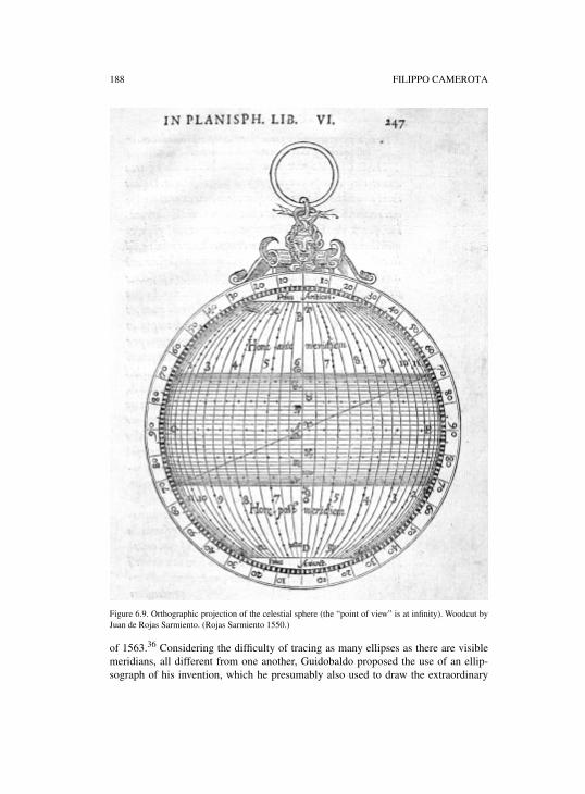
188 FILIPPO CAMEROTA
Figure 6.9. Orthographic projection of the celestial sphere (the “point of view” is at infinity). Woodcut byJuan de Rojas Sarmiento. (Rojas Sarmiento 1550.)
of 1563.36 Considering the difficulty of tracing as many ellipses as there are visiblemeridians, all different from one another, Guidobaldo proposed the use of an ellip-sograph of his invention, which he presumably also used to draw the extraordinary
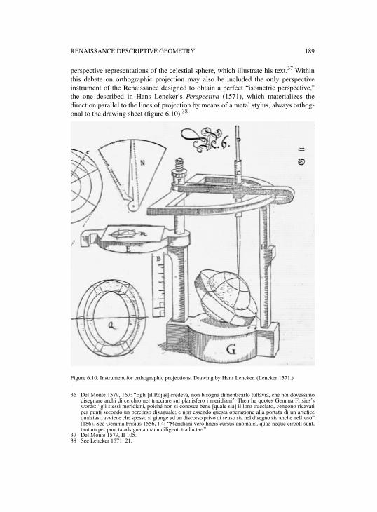
RENAISSANCE DESCRIPTIVE GEOMETRY 189
perspective representations of the celestial sphere, which illustrate his text.37 Withinthis debate on orthographic projection may also be included the only perspectiveinstrument of the Renaissance designed to obtain a perfect “isometric perspective,”the one described in Hans Lencker’s Perspectiva (1571), which materializes thedirection parallel to the lines of projection by means of a metal stylus, always orthog-onal to the drawing sheet (figure 6.10).38
Figure 6.10. Instrument for orthographic projections. Drawing by Hans Lencker. (Lencker 1571.)
36 Del Monte 1579, 167: “Egli [il Rojas] credeva, non bisogna dimenticarlo tuttavia, che noi dovessimodisegnare archi di cerchio nel tracciare sul planisfero i meridiani.” Then he quotes Gemma Frisius’swords: “gli stessi meridiani, poiché non si conosce bene [quale sia] il loro tracciato, vengono ricavatiper punti secondo un percorso disuguale; e non essendo questa operazione alla portata di un arteficequalsiasi, avviene che spesso si giunge ad un discorso privo di senso sia nel disegno sia anche nell’uso”(186). See Gemma Frisius 1556, I 4: “Meridiani verò lineis cursus anomalis, quae neque circoli sunt,tantum per puncta adsignata manu diligenti traductae.”
37 Del Monte 1579, II 105.38 See Lencker 1571, 21.
190 FILIPPO CAMEROTA
Figure 6.11. Orthographic projection of a human figure. Woodcut by Jean Cousin. (Cousin 1571.)
Apart from the doubts expressed by Guidobaldo del Monte, orthographic projec-tion was generally considered to be a perspective projection with the point of viewplaced at an infinite distance. Dürer and Jean Cousin showed how it could be used todraw the foreshortened human figure (figure 6.11). Galileo applied it to demonstratethe existence of sunspots; and Pietro Accolti, accepting the demonstrations of Gali-leo, conferred a physical image on the ideal point of orthographic projection, identi-fying it as “the eye of the Sun” (figure 6.12).39 Accolti mentions it within the contextof a discussion on the projection of shadows, comparing two representations of thesame cube, one seen by the eye of man and thus drawn in perspective—with the fore-shortened sides converging toward a vanishing point—the other seen by the eye ofthe sun, and consequently drawn in orthographic projection, with the foreshortenedsides parallel. “It is thus we consider that the aforesaid drawing should be, for repre-
39 See Dürer 1996, and Cousin 1571. Galileo employed parallel projection to explain the appearance ofsun spots in the telescope (Istoria e dimostrazioni intorno alle macchie solari e loro accidenti, Roma1613, 34; in Galilei 1890–1909, V 213–215). See Accolti 1625, III XXVIII, Altra invenzione perconseguire la naturale incidenza de lumi, et dell’ombre sopra diversi piani ove vanno a cadere: “Etinsegnandoci il testimonio del senso visivo … che il Sole … manda l’ombre sue, parallele sul piano …;così restiamo capaci potersi all’occhio nostro, et in disegno far rappresentazione di quella precisaveduta di qualsivoglia dato corpo, esposto all’occhio (per così dire) del Sole, quale ad esso Sole gli sirappresenta in veduta: … così intendiamo dover essere il suddetto disegno, per rappresentazione diveduta del Sole terminato con linee, et lati paralleli, et non occorrenti a punto alcuno in Prospettiva.”
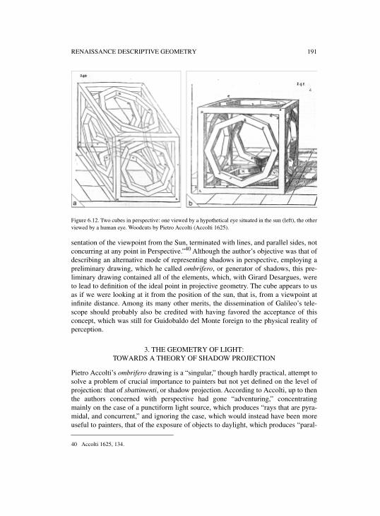
RENAISSANCE DESCRIPTIVE GEOMETRY 191
Figure 6.12. Two cubes in perspective: one viewed by a hypothetical eye situated in the sun (left), the otherviewed by a human eye. Woodcuts by Pietro Accolti (Accolti 1625).
sentation of the viewpoint from the Sun, terminated with lines, and parallel sides, notconcurring at any point in Perspective.”40 Although the author’s objective was that ofdescribing an alternative mode of representing shadows in perspective, employing apreliminary drawing, which he called ombrifero, or generator of shadows, this pre-liminary drawing contained all of the elements, which, with Girard Desargues, wereto lead to definition of the ideal point in projective geometry. The cube appears to usas if we were looking at it from the position of the sun, that is, from a viewpoint atinfinite distance. Among its many other merits, the dissemination of Galileo’s tele-scope should probably also be credited with having favored the acceptance of thisconcept, which was still for Guidobaldo del Monte foreign to the physical reality ofperception.
3. THE GEOMETRY OF LIGHT: TOWARDS A THEORY OF SHADOW PROJECTION
Pietro Accolti’s ombrifero drawing is a “singular,” though hardly practical, attempt tosolve a problem of crucial importance to painters but not yet defined on the level ofprojection: that of sbattimenti, or shadow projection. According to Accolti, up to thenthe authors concerned with perspective had gone “adventuring,” concentratingmainly on the case of a punctiform light source, which produces “rays that are pyra-midal, and concurrent,” and ignoring the case, which would instead have been moreuseful to painters, that of the exposure of objects to daylight, which produces “paral-
40 Accolti 1625, 134.
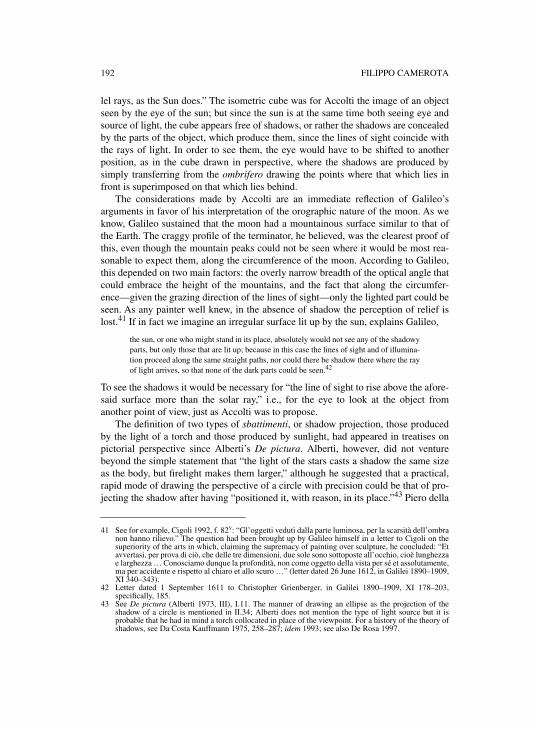
192 FILIPPO CAMEROTA
lel rays, as the Sun does.” The isometric cube was for Accolti the image of an objectseen by the eye of the sun; but since the sun is at the same time both seeing eye andsource of light, the cube appears free of shadows, or rather the shadows are concealedby the parts of the object, which produce them, since the lines of sight coincide withthe rays of light. In order to see them, the eye would have to be shifted to anotherposition, as in the cube drawn in perspective, where the shadows are produced bysimply transferring from the ombrifero drawing the points where that which lies infront is superimposed on that which lies behind.
The considerations made by Accolti are an immediate reflection of Galileo’sarguments in favor of his interpretation of the orographic nature of the moon. As weknow, Galileo sustained that the moon had a mountainous surface similar to that ofthe Earth. The craggy profile of the terminator, he believed, was the clearest proof ofthis, even though the mountain peaks could not be seen where it would be most rea-sonable to expect them, along the circumference of the moon. According to Galileo,this depended on two main factors: the overly narrow breadth of the optical angle thatcould embrace the height of the mountains, and the fact that along the circumfer-ence—given the grazing direction of the lines of sight—only the lighted part could beseen. As any painter well knew, in the absence of shadow the perception of relief islost.41 If in fact we imagine an irregular surface lit up by the sun, explains Galileo,
the sun, or one who might stand in its place, absolutely would not see any of the shadowyparts, but only those that are lit up; because in this case the lines of sight and of illumina-tion proceed along the same straight paths, nor could there be shadow there where the rayof light arrives, so that none of the dark parts could be seen.42
To see the shadows it would be necessary for “the line of sight to rise above the afore-said surface more than the solar ray,” i.e., for the eye to look at the object fromanother point of view, just as Accolti was to propose.
The definition of two types of sbattimenti, or shadow projection, those producedby the light of a torch and those produced by sunlight, had appeared in treatises onpictorial perspective since Alberti’s De pictura. Alberti, however, did not venturebeyond the simple statement that “the light of the stars casts a shadow the same sizeas the body, but firelight makes them larger,” although he suggested that a practical,rapid mode of drawing the perspective of a circle with precision could be that of pro-jecting the shadow after having “positioned it, with reason, in its place.”43 Piero della
41 See for example, Cigoli 1992, f. 82v: “Gl’oggetti veduti dalla parte luminosa, per la scarsità dell’ombranon hanno rilievo.” The question had been brought up by Galileo himself in a letter to Cigoli on thesuperiority of the arts in which, claiming the supremacy of painting over sculpture, he concluded: “Etavvertasi, per prova di ciò, che delle tre dimensioni, due sole sono sottoposte all’occhio, cioè lunghezzae larghezza … Conosciamo dunque la profondità, non come oggetto della vista per sé et assolutamente,ma per accidente e rispetto al chiaro et allo scuro …” (letter dated 26 June 1612, in Galilei 1890–1909,XI 340–343).
42 Letter dated 1 September 1611 to Christopher Grienberger, in Galilei 1890–1909, XI 178–203,specifically, 185.
43 See De pictura (Alberti 1973, III), I.11. The manner of drawing an ellipse as the projection of theshadow of a circle is mentioned in II.34; Alberti does not mention the type of light source but it isprobable that he had in mind a torch collocated in place of the viewpoint. For a history of the theory ofshadows, see Da Costa Kauffmann 1975, 258–287; idem 1993; see also De Rosa 1997.
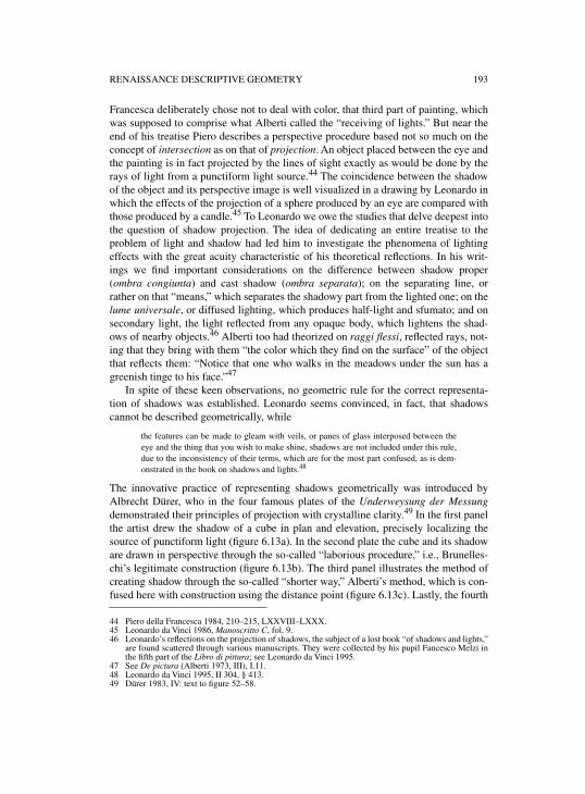
RENAISSANCE DESCRIPTIVE GEOMETRY 193
Francesca deliberately chose not to deal with color, that third part of painting, whichwas supposed to comprise what Alberti called the “receiving of lights.” But near theend of his treatise Piero describes a perspective procedure based not so much on theconcept of intersection as on that of projection. An object placed between the eye andthe painting is in fact projected by the lines of sight exactly as would be done by therays of light from a punctiform light source.44 The coincidence between the shadowof the object and its perspective image is well visualized in a drawing by Leonardo inwhich the effects of the projection of a sphere produced by an eye are compared withthose produced by a candle.45 To Leonardo we owe the studies that delve deepest intothe question of shadow projection. The idea of dedicating an entire treatise to theproblem of light and shadow had led him to investigate the phenomena of lightingeffects with the great acuity characteristic of his theoretical reflections. In his writ-ings we find important considerations on the difference between shadow proper(ombra congiunta) and cast shadow (ombra separata); on the separating line, orrather on that “means,” which separates the shadowy part from the lighted one; on thelume universale, or diffused lighting, which produces half-light and sfumato; and onsecondary light, the light reflected from any opaque body, which lightens the shad-ows of nearby objects.46 Alberti too had theorized on raggi flessi, reflected rays, not-ing that they bring with them “the color which they find on the surface” of the objectthat reflects them: “Notice that one who walks in the meadows under the sun has agreenish tinge to his face.”47
In spite of these keen observations, no geometric rule for the correct representa-tion of shadows was established. Leonardo seems convinced, in fact, that shadowscannot be described geometrically, while
the features can be made to gleam with veils, or panes of glass interposed between theeye and the thing that you wish to make shine, shadows are not included under this rule,due to the inconsistency of their terms, which are for the most part confused, as is dem-onstrated in the book on shadows and lights.48
The innovative practice of representing shadows geometrically was introduced byAlbrecht Dürer, who in the four famous plates of the Underweysung der Messungdemonstrated their principles of projection with crystalline clarity.49 In the first panelthe artist drew the shadow of a cube in plan and elevation, precisely localizing thesource of punctiform light (figure 6.13a). In the second plate the cube and its shadoware drawn in perspective through the so-called “laborious procedure,” i.e., Brunelles-chi’s legitimate construction (figure 6.13b). The third panel illustrates the method ofcreating shadow through the so-called “shorter way,” Alberti’s method, which is con-fused here with construction using the distance point (figure 6.13c). Lastly, the fourth
44 Piero della Francesca 1984, 210–215, LXXVIII–LXXX.45 Leonardo da Vinci 1986, Manoscritto C, fol. 9.46 Leonardo’s reflections on the projection of shadows, the subject of a lost book “of shadows and lights,”
are found scattered through various manuscripts. They were collected by his pupil Fancesco Melzi inthe fifth part of the Libro di pittura; see Leonardo da Vinci 1995.
47 See De pictura (Alberti 1973, III), I.11.48 Leonardo da Vinci 1995, II 304, § 413.49 Dürer 1983, IV: text to figure 52–58.
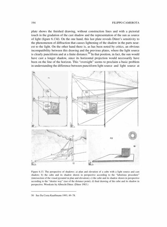
194 FILIPPO CAMEROTA
plate shows the finished drawing, without construction lines and with a pictorialtouch in the gradation of the cast shadow and the representation of the sun as sourceof light (figure 6.13d). On the one hand, this last plate reveals Dürer’s sensitivity tothe phenomenon of diffraction that causes lightening of the shadow in the parts near-est to the light. On the other hand there is, as has been noted by critics, an obviousincompatibility between this drawing and the previous plates, where the light sourceis clearly punctiform and at a finite distance.50 In that position, in fact, the sun wouldhave cast a longer shadow, since its horizontal projection would necessarily havebeen on the line of the horizon. This “oversight” seems to proclaim a basic problemin understanding the difference between punctiform light source and light source at
Figure 6.13. The perspective of shadows: a) plan and elevation of a cube with a light source and castshadow; b) the cube and its shadow drawn in perspective according to the “laborious procedure”(intersection of the visual pyramid in plan and elevation); c) the cube and its shadow drawn in perspectiveaccording to the “shorter way” (use of the distance point); d) final drawing of the cube and its shadow inperspective. Woodcuts by Albrecht Dürer. (Dürer 1983.)
50 See Da Costa Kauffmann 1993, 49–78.
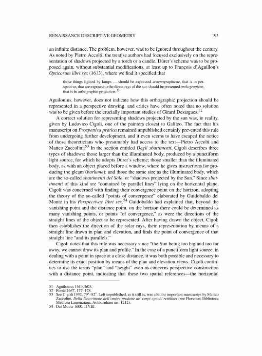
RENAISSANCE DESCRIPTIVE GEOMETRY 195
an infinite distance. The problem, however, was to be ignored throughout the century.As noted by Pietro Accolti, the treatise authors had focused exclusively on the repre-sentation of shadows projected by a torch or a candle. Dürer’s scheme was to be pro-posed again, without substantial modifications, at least up to François d’Aguillon’sOpticorum libri sex (1613), where we find it specified that
those things lighted by lamps … should be expressed scaenographicae, that is in per-spective, that are exposed to the direct rays of the sun should be presented orthograpicae,that is in orthographic projection.51
Aguilonius, however, does not indicate how this orthographic projection should berepresented in a perspective drawing, and critics have often noted that no solutionwas to be given before the crucially important studies of Girard Desargues.52
A correct solution for representing shadows projected by the sun was, in reality,given by Ludovico Cigoli, one of the painters closest to Galileo. The fact that hismanuscript on Prospettiva pratica remained unpublished certainly prevented this rulefrom undergoing further development, and it even seems to have escaped the noticeof those theoreticians who presumably had access to the text—Pietro Accolti andMatteo Zaccolini.53 In the section entitled Degli sbattimenti, Cigoli describes threetypes of shadows: those larger than the illuminated body, produced by a punctiformlight source, for which he adopts Dürer’s scheme; those smaller than the illuminatedbody, as with an object placed before a window, where he gives instructions for pro-ducing the gleam (barlume); and those the same size as the illuminated body, whichare the so-called sbattimenti del Sole, or “shadows projected by the Sun.” Since sbat-timenti of this kind are “contained by parallel lines” lying on the horizontal plane,Cigoli was concerned with finding their convergence point on the horizon, adoptingthe theory of the so-called “points of convergence” elaborated by Guidobaldo delMonte in his Perspectivae libri sex.54 Guidobaldo had explained that, beyond thevanishing point and the distance point, on the horizon there could be determined asmany vanishing points, or points “of convergence,” as were the directions of thestraight lines of the object to be represented. After having drawn the object, Cigolithen establishes the direction of the solar rays, their representation by means of astraight line drawn in plan and elevation, and finds the point of convergence of thatstraight line “and its parallels.”
Cigoli notes that this rule was necessary since “the Sun being too big and too faraway, we cannot draw its plan and profile.” In the case of a punctiform light source, indealing with a point in space at a close distance, it was both possible and necessary todetermine its exact position by means of the plan and elevation views. Cigoli contin-ues to use the terms “plan” and “height” even as concerns perspective constructionwith a distance point, indicating that these two spatial references—the horizontal
51 Aguilonius 1613, 683.52 Bosse 1647, 177–178.53 See Cigoli 1992, 79v–82v. Left unpublished, as it still is, was also the important manuscript by Matteo
Zaccolini, Della Descritione dell’ombre prodotte de’ corpi opachi rettilinei (see Florence; BibliotecaMedicea Laurenziana, Ashburnham ms. 1212).
54 Del Monte 1600, II VIff.
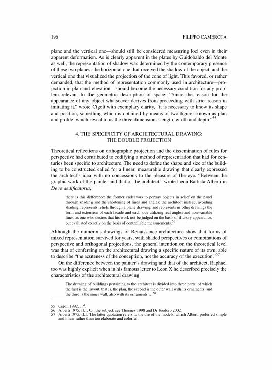
196 FILIPPO CAMEROTA
plane and the vertical one—should still be considered measuring loci even in theirapparent deformation. As is clearly apparent in the plates by Guidobaldo del Monteas well, the representation of shadow was determined by the contemporary presenceof these two planes: the horizontal one that received the shadow of the object, and thevertical one that visualized the projection of the cone of light. This favored, or ratherdemanded, that the method of representation commonly used in architecture—pro-jection in plan and elevation—should become the necessary condition for any prob-lem relevant to the geometric description of space: “Since the reason for theappearance of any object whatsoever derives from proceeding with strict reason inimitating it,” wrote Cigoli with exemplary clarity, “it is necessary to know its shapeand position, something which is obtained by means of two figures known as planand profile, which reveal to us the three dimensions: length, width and depth.”55
4. THE SPECIFICITY OF ARCHITECTURAL DRAWING: THE DOUBLE PROJECTION
Theoretical reflections on orthographic projection and the dissemination of rules forperspective had contributed to codifying a method of representation that had for cen-turies been specific to architecture. The need to define the shape and size of the build-ing to be constructed called for a linear, measurable drawing that clearly expressedthe architect’s idea with no concessions to the pleasure of the eye. “Between thegraphic work of the painter and that of the architect,” wrote Leon Battista Alberti inDe re aedificatoria,
there is this difference: the former endeavors to portray objects in relief on the panelthrough shading and the shortening of lines and angles; the architect instead, avoidingshading, represents reliefs through a plane drawing, and represents in other drawings theform and extension of each facade and each side utilizing real angles and non-variablelines, as one who desires that his work not be judged on the basis of illusory appearance,but evaluated exactly on the basis of controllable measurements.56
Although the numerous drawings of Renaissance architecture show that forms ofmixed representation survived for years, with shaded perspectives or combinations ofperspective and orthogonal projections, the general intention on the theoretical levelwas that of conferring on the architectural drawing a specific nature of its own, ableto describe “the acuteness of the conception, not the accuracy of the execution.”57
On the difference between the painter’s drawing and that of the architect, Raphaeltoo was highly explicit when in his famous letter to Leon X he described precisely thecharacteristics of the architectural drawing:
The drawing of buildings pertaining to the architect is divided into three parts, of whichthe first is the layout, that is, the plan, the second is the outer wall with its ornaments, andthe third is the inner wall, also with its ornaments …58
55 Cigoli 1992, 17r.56 Alberti 1975, II.1. On the subject, see Thoenes 1998 and Di Teodoro 2002.57 Alberti 1975, II.1. The latter quotation refers to the use of the models, which Alberti preferred simple
and linear rather than too elaborate and colorful.
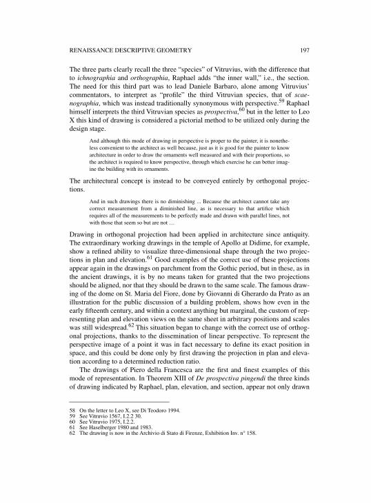
RENAISSANCE DESCRIPTIVE GEOMETRY 197
The three parts clearly recall the three “species” of Vitruvius, with the difference thatto ichnographia and orthographia, Raphael adds “the inner wall,” i.e., the section.The need for this third part was to lead Daniele Barbaro, alone among Vitruvius’commentators, to interpret as “profile” the third Vitruvian species, that of scae-nographia, which was instead traditionally synonymous with perspective.59 Raphaelhimself interprets the third Vitruvian species as prospectiva,60 but in the letter to LeoX this kind of drawing is considered a pictorial method to be utilized only during thedesign stage.
And although this mode of drawing in perspective is proper to the painter, it is nonethe-less convenient to the architect as well because, just as it is good for the painter to knowarchitecture in order to draw the ornaments well measured and with their proportions, sothe architect is required to know perspective, through which exercise he can better imag-ine the building with its ornaments.
The architectural concept is instead to be conveyed entirely by orthogonal projec-tions.
And in such drawings there is no diminishing ... Because the architect cannot take anycorrect measurement from a diminished line, as is necessary to that artifice whichrequires all of the measurements to be perfectly made and drawn with parallel lines, notwith those that seem so but are not …
Drawing in orthogonal projection had been applied in architecture since antiquity.The extraordinary working drawings in the temple of Apollo at Didime, for example,show a refined ability to visualize three-dimensional shape through the two projec-tions in plan and elevation.61 Good examples of the correct use of these projectionsappear again in the drawings on parchment from the Gothic period, but in these, as inthe ancient drawings, it is by no means taken for granted that the two projectionsshould be aligned, nor that they should be drawn to the same scale. The famous draw-ing of the dome on St. Maria del Fiore, done by Giovanni di Gherardo da Prato as anillustration for the public discussion of a building problem, shows how even in theearly fifteenth century, and within a context anything but marginal, the custom of rep-resenting plan and elevation views on the same sheet in arbitrary positions and scaleswas still widespread.62 This situation began to change with the correct use of orthog-onal projections, thanks to the dissemination of linear perspective. To represent theperspective image of a point it was in fact necessary to define its exact position inspace, and this could be done only by first drawing the projection in plan and eleva-tion according to a determined reduction ratio.
The drawings of Piero della Francesca are the first and finest examples of thismode of representation. In Theorem XIII of De prospectiva pingendi the three kindsof drawing indicated by Raphael, plan, elevation, and section, appear not only drawn
58 On the letter to Leo X, see Di Teodoro 1994.59 See Vitruvio 1567, I.2.2 30.60 See Vitruvio 1975, I.2.2.61 See Haselberger 1980 and 1983.62 The drawing is now in the Archivio di Stato di Firenze, Exhibition Inv. n° 158.
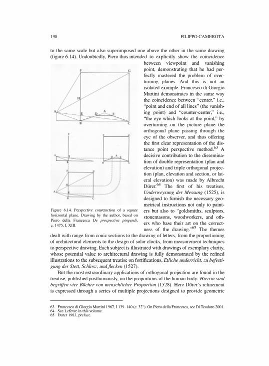
198 FILIPPO CAMEROTA
to the same scale but also superimposed one above the other in the same drawing(figure 6.14). Undoubtedly, Piero thus intended to explicitly show the coincidence
between viewpoint and vanishingpoint, demonstrating that he had per-fectly mastered the problem of over-turning planes. And this is not anisolated example. Francesco di GiorgioMartini demonstrates in the same waythe coincidence between “center,” i.e.,“point and end of all lines” (the vanish-ing point) and “counter-center,” i.e.,“the eye which looks at the point,” byoverturning on the picture plane theorthogonal plane passing through theeye of the observer, and thus offeringthe first clear representation of the dis-tance point perspective method.63 Adecisive contribution to the dissemina-tion of double representation (plan andelevation) and triple orthogonal projec-tion (plan, elevation and section, or lat-eral elevation) was made by AlbrechtDürer.64 The first of his treatises,Underweysung der Messung (1525), isdesigned to furnish the necessary geo-metrical instructions not only to paint-ers but also to “goldsmiths, sculptors,stonemasons, woodworkers, and oth-ers who base their art on the correct-ness of the drawing.”65 The themes
dealt with range from conic sections to the drawing of letters, from the proportioningof architectural elements to the design of solar clocks, from measurement techniquesto perspective drawing. Each subject is illustrated with drawings of exemplary clarity,whose potential value to architectural drawing is fully demonstrated by the refinedillustrations to the subsequent treatise on fortifications, Etliche underricht, zu befesti-gung der Stett, Schlosz, und flecken (1527).
But the most extraordinary applications of orthogonal projection are found in thetreatise, published posthumously, on the proportions of the human body: Hieirin sindbegriffen vier Bücher von menschlicher Proportion (1528). Here Dürer’s refinementis expressed through a series of multiple projections designed to provide geometric
63 Francesco di Giorgio Martini 1967, I 139–140 (c. 32v). On Piero della Francesca, see Di Teodoro 2001.64 See Lefèvre in this volume.65 Dürer 1983, preface.
Figure 6.14. Perspective construction of a squarehorizontal plane. Drawing by the author, based onPiero della Francesca De prospectiva pingendi,c. 1475, I, XIII.
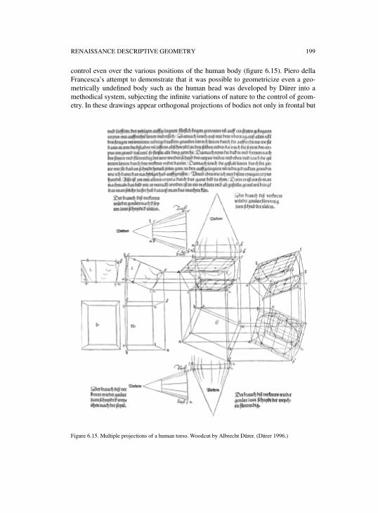
RENAISSANCE DESCRIPTIVE GEOMETRY 199
control even over the various positions of the human body (figure 6.15). Piero dellaFrancesca’s attempt to demonstrate that it was possible to geometricize even a geo-metrically undefined body such as the human head was developed by Dürer into amethodical system, subjecting the infinite variations of nature to the control of geom-etry. In these drawings appear orthogonal projections of bodies not only in frontal but
Figure 6.15. Multiple projections of a human torso. Woodcut by Albrecht Dürer. (Dürer 1996.)
200 FILIPPO CAMEROTA
also in oblique view, seen from below or above: real stereometries of human torsos,limbs and heads. Educated in a family of goldsmiths, Dürer possessed the expertise todominate almost entirely the field of geometric constructions, but he himself statedthat this type of drawing originated in a precise professional context, that of thestonemasons. In his dedication to Willibald Pirckheimer, he in fact writes that who-ever wishes to confront the study of proportions must have
well assimilated the manner of measuring and must have understood how all things mustbe extracted from the plan and elevation, according to the method daily practiced by thestonemasons.66
5. STONEMASONS’ GEOMETRY: ROTATION, OVERTURNING, AND DEVELOPMENT
According to Dürer, construction sites were the places where drawing was practicedat its highest level. On construction sites, the transition from the project drawing toactual construction was made through two basic elements: the wooden model—which visualized the building in three dimensions, furnishing all of the informationnecessary for carrying out the work, from construction system to decoration—and theworking drawing on the scale of 1:1, which furnished the exact measurements of eachindividual architectural element. The working drawings were carried out on the siteprogressively as construction proceeded, so that each new element to be worked, inwood or in stone, could be perfectly adapted to the part already constructed. Thesedrawings were made, under the supervision of the architect, by the carpenters orstonemasons themselves, who then had to shape each architectural element from aformless beam or a rough-hewn block of stone. The previously mentioned drawingsof the Temple of Apollo at Didime show exactly this process of detailed definition ofdimensions and shapes. The drawings, engraved in stone, would have furnished thenecessary information to all of the stonemasons who succeeded one another duringthe long period of construction of the building. Similar graphic documents are foundin some Gothic cathedrals, as for example on the terrace of the choir in the Cathedralof Clermont-Ferrand, where a drawing on the scale of 1:1 of one of the portals on thefacade has survived.67
The working drawing had to be extremely precise, detailed but also essential, freefrom any sign that had no structural function. The essential nature of such drawings isclearly indicated by the manuals of Matthäus Roriczer and Hans Schmuttermayer,who divulge for the first time the “secrets” of the worksite drawing, revealing howknowledge of the method applied to extract the elevation from the plan had favored astratagem that today would be called ergonomic. By utilizing a particular geometric
66 Dürer 1996, letter of dedication to Willibald Pirckheimer: “Darumb thut einem yglichen der sich diserkunst vndersteen will not / das er zuuor der messung wol vnderricht sey / vnd einen verstand vberkome/ wie alle ding in grund gelegt / vnd auffgezogen sollen werden / wie dann die kunstlichen Steinmetzenin teglichem geprauch habenn.”
67 The drawing is an elevation of the northern portal of the Cathedral of Clermont-Ferrand; seeSakarovitch 1998, 126.
RENAISSANCE DESCRIPTIVE GEOMETRY 201
figure—a square inscribed in another square rotated 45°—it was possible to deductfrom the plan drawing alone the widths of all of the other points in the piece to beworked.68 A particularly vivid picture of the techniques employed in medieval work-sites appears in the famous notebook of Villard de Honnecourt, which describes vari-ous graphic procedures for proportioning architectural elements and the humanfigure, enlarging the size of the design drawing to that of the working drawing, mea-suring heights and distances, tracing pointed arches and, above all, for designingcomplex structural features such as a stone arch over an oblique passageway or in acircular wall.69
Building this type of arch called for great technical skill that implicated anuncommon knowledge of static and geometric factors. The oblique vault was gener-ated from a cylinder that traversed a straight parallelepiped, i.e., the wall thickness, atan angle. For the arch to fulfill its static function, the joints between the ashlars had tolie on planes perpendicular to the wall sector. Due to the oblique nature of the pas-sage, the intrados surfaces of the various ashlars were not uniformly curved buttwisted to varying degrees, and the joint lines appeared as elliptical segments. In alllikelihood the problem was solved through a method now termed “by squaring,”which consisted of obtaining the oblique piece from the cubic block by the orthogo-nal projection of its shape onto the faces of the cube. The ensemble of the six orthog-onal projections, which make up a cube is precisely the system adopted by Dürer inrepresenting the stereometry of the human torso, and it is presumably this method towhich the German painter was referring in the passage quoted above.
In his drawings Villard illustrates how these problems of stereotomy could besolved on the worksite by the appropriate use of a square or ruler. The use of theseinstruments, however, seems to implicate the knowledge of a more refined system ofgeometric projections. In addition to the square and the ruler, Villard traces signs,which indicate the number of ashlars of which the arch is composed and the angles ofthe different cuts necessary to transform the cubic block of a single ashlar into anoblique parallelepiped. The problem was probably solved with the aid of scale mod-els, but the signs left by Villard hint at the application of a graphic procedure notunlike the one codified later in subsequent treatises on stereotomy. The first descrip-tion of the drawing methods employed by stonecutters was given by Philibert DeL’Orme, whose Premier tome de l’architecture (1567) constitutes today, under thisaspect, an exception in the panorama of Renaissance architectural treatises.70 BooksIII and IV of this important treatise are entirely dedicated to “the art of stone cutting,”which is presented here essentially as the “art of geometric drawing,” indicating thatthe problem of cutting stones lay above all in the correct execution of the drawing.The importance attributed by De L’Orme to this aspect of architecture emergesalready in the title-page, where eight “stereotomic icons” illustrate the graphic reso-lution of some of the most significant cases of stereotomy: the hemispheric vault, the
68 Roritzer 1486; Schmuttermayer 1489.69 See Bechman 1993.70 De L’Orme 1567. On the subject of stereotomy in the work of De L’Orme, see Pérouse de Montclos
2000; Potié 1996; Sakarovitch 1998.
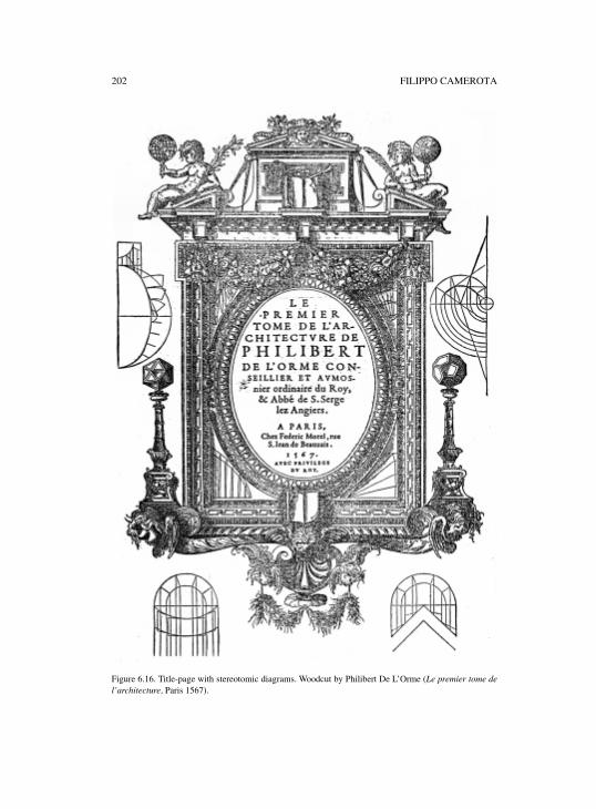
202 FILIPPO CAMEROTA
Figure 6.16. Title-page with stereotomic diagrams. Woodcut by Philibert De L’Orme (Le premier tome del’architecture, Paris 1567).
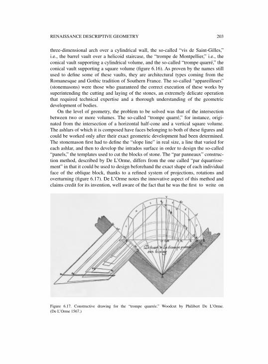
RENAISSANCE DESCRIPTIVE GEOMETRY 203
three-dimensional arch over a cylindrical wall, the so-called “vis de Saint-Gilles,”i.e., the barrel vault over a helicoid staircase, the “trompe de Montpellier,” i.e., theconical vault supporting a cylindrical volume, and the so-called “trompe quarré,” theconical vault supporting a square volume (figure 6.16). As proven by the names stillused to define some of these vaults, they are architectural types coming from theRomanesque and Gothic tradition of Southern France. The so-called “appareilleurs”(stonemasons) were those who guaranteed the correct execution of these works bysuperintending the cutting and laying of the stones, an extremely delicate operationthat required technical expertise and a thorough understanding of the geometricdevelopment of bodies.
On the level of geometry, the problem to be solved was that of the intersectionbetween two or more volumes. The so-called “trompe quarré,” for instance, origi-nated from the intersection of a horizontal half-cone and a vertical square volume.The ashlars of which it is composed have faces belonging to both of these figures andcould be worked only after their exact geometric development had been determined.The stonemason first had to define the “slope line” in real size, a line that varied foreach ashlar, and then to develop the intrados surface in order to design the so-called“panels,” the templates used to cut the blocks of stone. The “par panneaux” construc-tion method, described by De L’Orme, differs from the one called “par équarrisse-ment” in that it could be used to design beforehand the exact shape of each individualface of the oblique block, thanks to a refined system of projections, rotations andoverturning (figure 6.17). De L’Orme notes the innovative aspect of this method andclaims credit for its invention, well aware of the fact that he was the first to write on
Figure 6.17. Constructive drawing for the “trompe quarrée.” Woodcut by Philibert De L’Orme.(De L’Orme 1567.)
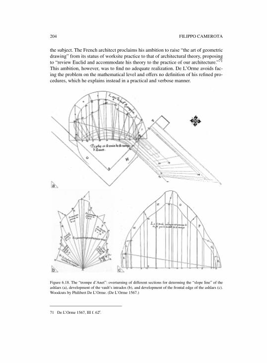
204 FILIPPO CAMEROTA
the subject. The French architect proclaims his ambition to raise “the art of geometricdrawing” from its status of worksite practice to that of architectural theory, proposingto “review Euclid and accommodate his theory to the practice of our architecture.”71
This ambition, however, was to find no adequate realization. De L’Orme avoids fac-ing the problem on the mathematical level and offers no definition of his refined pro-cedures, which he explains instead in a practical and verbose manner.
Figure 6.18. The “trompe d’Anet”: overturning of different sections for determing the “slope line” of theashlars (a), development of the vault’s intrados (b), and development of the frontal edge of the ashlars (c).Woodcuts by Philibert De L’Orme. (De L’Orme 1567.)
71 De L’Orme 1567, III f. 62r.
RENAISSANCE DESCRIPTIVE GEOMETRY 205
The design of the “panels” can be compared to the development of the faces of thepolyhedrons and the sphere illustrated by Albrecht Dürer, in his treatise on geometrydesigned to teach how to construct those geometric solids materially.72 But while thefaces of the polyhedrons are all regular geometric figures—triangles, squares, penta-gons, hexagons, and lunes in the case of the sphere—the faces of an oblique ashlarare irregular figures, also delimited by curved lines. In the absence of earlier graphictestimony, we must believe that De L’Orme’s method consisted exclusively of totalmastery of drawing; that is, of the application of a general projection principle, whichcan be used to resolve not merely a particular shape but any invention the architect iscapable of imagining. Not by chance a large portion of the two books on stonecuttingis dedicated to the detailed explanation and illustration of a new “trompe,” of whichDe L’Orme writes, “I am certain that no worker in this kingdom has ever heard tell ofit before.”73 This was the “trompe surbaissée, bias et rampante,” a variation of the“trompe de Montpellier” distinguished by an elliptical shape, a rampant arch, of thegeneratrix of the cone. The invention of this “trompe” dates from 1536, when DeL’Orme, upon returning from his voyage to Rome, built the first example of it in theHôtel Bullioud at Lyon. About ten years later he created an even more refined varia-tion in the Castle of Anet, which represents his masterpiece of stereotomy (figure6.18). While the “trompe” of Lyon supported a simple cylindrical volume, that ofAnet bore up a mixtilinear cylinder, which conferred on the line of intersection withthe elliptical cone an undulating profile of bold audacity, both technically and for-mally: “which I wanted to make of a form so strange as to render the trompe of thevault more difficult, and beautiful to behold.”74
De L’Orme evidently pursued a stereotomic virtuosity that emerged as a stylisticsign, and sought a new aesthetics based on geometry rather than on ornamentation.And it was in the name of this principle, in fact, that he criticized the father of Renais-sance classicism, Donato Bramante, whose helicoid staircase in the Vatican Belved-ere he considered an exemplary case of geometric incongruity. “If the architect whobuilt it had known the geometric method of which I speak,” wrote De L’Orme, hewould have operated so that each element followed the geometric nature of helicoiddevelopment, even the bases and the capitals of the columns, which instead, in keep-ing with Vitruvius’ rules, Bramante had drawn as if they supported “a straight, hori-zontal portico.”75 This geometric incongruity is also criticized by Juan Caramuel deLobkowitz who in the next century was to base the principles of “oblique architec-ture” expressly on stereotomic geometry.76 The solution suggested by De L’Orme forBramante’s staircase is the one employed in the tribune of the Cathedral of Saint-Éti-enne-du-Mont in Paris, which also appears in a drawing in the Louvre traditionallyattributed to the French architect.77 Of the helicoid staircase built in the Castle of
72 See Dürer 1983, IV figure 29–34.73 De L’Orme 1567, IV 91r.74 Idem, IV.2 89.75 Idem, IV.19 124.76 Caramuel de Lobkowitz 1678, tratado VI, articulo XII.77 Paris, Cabinet des Dessins du Louvre, n. 11114; see Blunt 1958, figure 139.
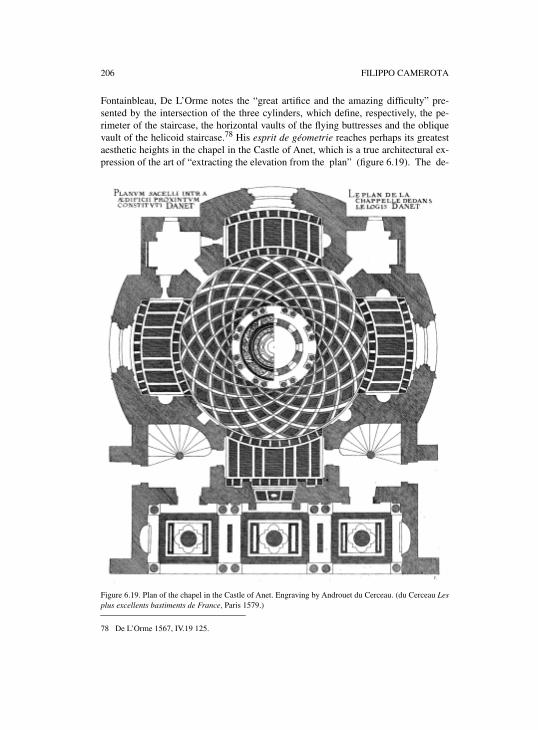
206 FILIPPO CAMEROTA
Fontainbleau, De L’Orme notes the “great artifice and the amazing difficulty” pre-sented by the intersection of the three cylinders, which define, respectively, the pe-rimeter of the staircase, the horizontal vaults of the flying buttresses and the obliquevault of the helicoid staircase.78 His esprit de géometrie reaches perhaps its greatestaesthetic heights in the chapel in the Castle of Anet, which is a true architectural ex-pression of the art of “extracting the elevation from the plan” (figure 6.19). The de-
Figure 6.19. Plan of the chapel in the Castle of Anet. Engraving by Androuet du Cerceau. (du Cerceau Lesplus excellents bastiments de France, Paris 1579.)
78 De L’Orme 1567, IV.19 125.
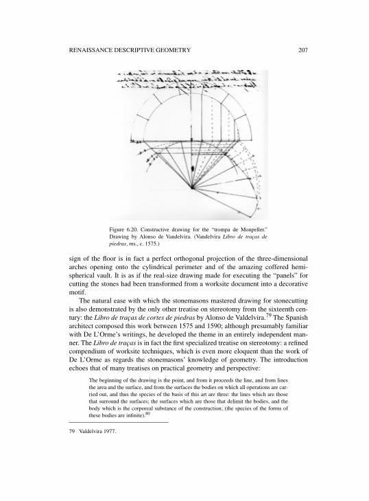
RENAISSANCE DESCRIPTIVE GEOMETRY 207
.
sign of the floor is in fact a perfect orthogonal projection of the three-dimensionalarches opening onto the cylindrical perimeter and of the amazing coffered hemi-spherical vault. It is as if the real-size drawing made for executing the “panels” forcutting the stones had been transformed from a worksite document into a decorativemotif.
The natural ease with which the stonemasons mastered drawing for stonecuttingis also demonstrated by the only other treatise on stereotomy from the sixteenth cen-tury: the Libro de traças de cortes de piedras by Alonso de Valdelvira.79 The Spanisharchitect composed this work between 1575 and 1590; although presumably familiarwith De L’Orme’s writings, he developed the theme in an entirely independent man-ner. The Libro de traças is in fact the first specialized treatise on stereotomy: a refinedcompendium of worksite techniques, which is even more eloquent than the work ofDe L’Orme as regards the stonemasons’ knowledge of geometry. The introductionechoes that of many treatises on practical geometry and perspective:
The beginning of the drawing is the point, and from it proceeds the line, and from linesthe area and the surface, and from the surfaces the bodies on which all operations are car-ried out, and thus the species of the basis of this art are three: the lines which are thosethat surround the surfaces; the surfaces which are those that delimit the bodies, and thebody which is the corporeal substance of the construction; (the species of the forms ofthese bodies are infinite).80
79 Valdelvira 1977.
Figure 6.20. Constructive drawing for the “trompa de Monpeller.”Drawing by Alonso de Vandelvira. (Vandelvira Libro de traças depiedras, ms., c. 1575.)
208 FILIPPO CAMEROTA
As to the individual stone ashlar a description is given of each of its six faces, themethod for determining its shape, and the instrument used to work it and to verify itsinstallation: a mobile square called baivel (biveau in French). In the construction ofthe “trompa de Monpeller,” Vandelvira applies a method slightly different from thatof De L’Orme, which allows less superimposition of the graphic indications and thuseasier reading of the drawing (figure 6.20). While De L’Orme draws the generatrix ofthe cone on a secant plane, passing through the points at which the cylindrical vol-ume meets the rectilinear walls of the building, Vandelvira plots it on a tangent plane,displaying the intersection between the volumes much more clearly. Furthermore, theSpanish architect does not effect overturning to find the “slope line,” but immediatelyconstructs the development of the cone, which visualizes the true shape of the intra-dos “panels.”
Vandelvira’s method also shows how the problem to be solved was that of deter-mining the transformation of geometric figures: a plane arch that is transformed intoa three-dimensional arch for example, or a circle that is transformed into an ellipse.The concept of projection is implicit but not necessarily present in all of these opera-tions. Only with the work of Girard Desargues did it become certain that this geome-try of transformations was knowledgeably based on universally valid principles ofprojection. “This manner of carrying out drawings for the cutting of stones,” writesDesargues in the Pratique du trait (1643), “is the same as the method of practicingperspective without employing any third point of distance, or of any other type, thatlies outside of the painting …” And further on he reiterates:
… so that there is no difference between the manner of depicting, reducing or represent-ing anything in perspective, and the manner of depicting, reducing or representing in ageometrical drawing, so that geometrical drawing and perspective are no other than twospecies of the same gender, which can be enunciated or demonstrated together, using thesame words …81
Viewed in the light of hindsight, this truth emerged throughout the Renaissance.Albrecht Dürer, in particular, was the artist who came closest to a general formulationof “descriptive geometry.” He put together the technical and geometric knowledge ofmany professional categories—painters, architects, cartographers, stonemasons,astronomers and instrument makers—demonstrating how the dottrina of drawinglodged in the workshops of craftsmen more than in the minds of geometers. He him-self invented new graphic and mechanical procedures for geometric drawing: multi-ple orthogonal projections, the projection of shadows, the famous perspectiveinstruments, and the extraordinary compasses for drawing ellipses, spirals, and newcurves not yet defined on the geometric level. His numerous technical and geometricinventions, often developed and experimented within the workshops, and subse-quently disseminated through the press, are a striking example of how ingenuity pro-gressively favored the evolution of drawing toward a doctrine that was later to bereinforced by the geometric concepts of infinity, projection, and homology.
80 Idem, introduction.81 See Desargues 1640; in Desargues 1864, I 305–362 (in particular, 305ff.).
7
THE EMERGENCE OF COMBINED ORTHOGRAPHIC PROJECTIONS
WOLFGANG LEFÈVRE
INTRODUCTION
Modern engineering employs all kinds of drawings—from sketches, over severalorthographic plans and combinations of such plans, through a variety of schematicsand diagrams, up to all sorts of illustration drawings in perspective.1 Plans, and inparticular combined plans, constitute the core of this abundance of engineering draw-ings, at least in the process of designing and manufacturing.2 It is therefore surprisingthat plans are rather the exception than the rule among the drawings traced and usedby engineers of the Renaissance.3 From Taccola’s well-known illustrated manuscriptsof the first half of the fifteenth century up to the famous Theatres of Machines of thelate sixteenth century, perspective drawings dominate the picture. And of the fewplans known from this age, hardly any could be called a blueprint in the presentunderstanding of the term.
Destruction or interrupted transmission can be ruled out as the main causes of thisremarkable absence of plans,4 which thus indicates a practice of engineering that, asa rule, designed and manufactured intricate devices without plans. A reconstructionof this praxis must focus on issues like the organization and division of labor inprojects where engineers were involved, the prevalence of adaptations of traditionalsolutions to local circumstances, the almost complete lack of manufacturing the dif-ferent parts of a mill, a water lifting device or a machine at different locations, therole of models and templates, the education of the craftsmen, and so on.
However, such a reconstruction of a practice of engineering without plans caneasily be mistaken as an explanation of the absence of plans that argues: Since theseengineers could do without plans, they didn’t take pains to construct ones. But thisconclusion is only valid if one can presuppose that Renaissance engineers would havebeen able to construct plans if they had wanted to. Are there reasons to assume thatthey had sufficient command of the techniques necessary for drawing orthographicplans? Now the fact that almost all of them also worked as architects appears to be a
1 See, for instance, Rising and Amfeldt 1964. 2 I disregard here the sweeping changes that the computer and specific electronic applications for
engineering drawing brought about in the design process during the last two decades.3 See Lefèvre 2003.4 By their very nature, plans that actually served as a means of designing and manufacturing can be
expected only either in the private files of the engineers themselves and of private customers, or in thearchives of public commissioners. And it is rather probable that many of these documents are indeedlost. However, the few cases where such materials survived and are known confirm the overall pictureof the marginality of plans in the realm of Renaissance engineering. The Württemberg engineer andarchitect Heinrich Schickhardt (1558–1635), whose private files are preserved and held in theHauptstaatsarchiv Stuttgart, is probably a good case in point—see Popplow 1999.
210 WOLFGANG LEFÈVRE
very strong indication. Rather, what seems to require explanation is the strange factthat people who were familiar with orthographic plans when constructing buildingsvery rarely took advantage of these means when functioning as engineers. But again,this involves an unproven presupposition. This time, one would assume that all basictechniques of constructing orthographic plans were known and employed in therealm of Renaissance architecture. But is this true?
In the literature on Renaissance engineering, architecture, or perspective painting,it often is taken for granted that the engineers and architects of this age had basicallythe same techniques of constructing plans at their disposal as their modern col-leagues. Since the drawing of orthogonal plans is considered a rather trivial task incontrast to perspective depiction, the technique of constructing plans is usually sup-posed to be given where plans occur: for instance, in ancient Mesopotamia or ancientEgypt. The technique of constructing plans, thus, has the appearance of a culturalachievement without a really historic development: its origin is hidden in the dawn ofthe earliest cultural developments, and its history seems to be that of a mere technicalrefinement of a procedure, the essence of which was given with its first invention andremained the same up to the present day.
The period under scrutiny here proves that this picture is wrong. For the Renais-sance was the time of a decisive turn in the history of plan construction. The double-faced character of such periods of change is clearly discernible. On the one hand, oneencounters techniques and conventions of producing plans that differ distinctivelyfrom present ones, not only in some secondary aspects, but in substance. (And onemay ask whether the plans from the Renaissance convey an impression of how thetechnique of constructing plans might have looked in earlier ages, not only in theGothic period, which is essentially the same with respect to plans, but also in classicAntiquity.) On the other hand, the modern techniques of constructing plans wereactually invented—albeit rarely employed—in just this period. This chapter, there-fore, has two goals. It tries to show that Renaissance (and Gothic) plan constructionwas not based on a technique that is essential for present-day plan construction,namely the combined views technique. Furthermore, it tries to show that this tech-nique was invented at the turn of the fifteenth century and introduced to architectureby Antonio da Sangallo the Younger and Albrecht Dürer in the second decade of thesixteenth century, and that it took the entire sixteenth century before it became a stan-dard technique in architecture.
Before coming to how the chapter proceeds, a brief clarification of terms likeplan, elevation, and combined views may be useful. In this chapter, the term “plan”denotes any kind of orthographic projection, that is, a projection where each line thatconnects a point of the depicted object with its representation on the drawing meetsthe drawing plane at right angles.5 In this way, it is warranted that plans depict trueangles and true distances, or, in the case of scaled plans, true proportions among dis-tances. It is this fidelity with regard to angles and distances that gives plans their spe-
5 More precisely, I use the term “plan” to denote all kinds of multiplanar orthographic projections. For acontemporary classification of projections, see, for instance, French 1947, 91.
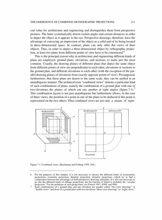
THE EMERGENCE OF COMBINED ORTHOGRAPHIC PROJECTIONS 211
cial value for architecture and engineering and distinguishes them from perspectivepictures. The latter systematically distort certain angles and certain distances in orderto depict the object as it appears to the eye. Perspective drawings, therefore, have theadvantage of conveying an impression of the object as a solid and of its being locatedin three-dimensional space. In contrast, plans can only offer flat views of theirobjects. Thus, in order to depict a three-dimensional object by orthographic projec-tion, at least two plans from different points of view have to be constructed.6
This is the principal reason why in architecture and engineering different kinds ofplans are employed: ground plans, elevations, and sections, to name just the mostcommon. Usually, the drawing planes of different plans that depict the same objectfrom different points of view are perpendicular to each other, elevations or sections tothe ground plan, and different elevations to each other (with the exception of the par-allel drawing planes of elevations from exactly opposite points of view). Presupposed,furthermore, that these plans are drawn to the same scale, they can be unified in anunambiguous manner. The technical term “combined views” denotes a particular kindof such combinations of plans, namely the combination of a ground plan with one ortwo elevations, the planes of which cut one another at right angles (figure 7.1).7
This combination layout is not just unambiguous but furthermore allows, in the caseof three views, the position of a point in one of the plans to be deduced if this point isrepresented on the two others. Thus combined views are not only a means of repre-
Figure 7.1. Combined views. (Bachmann and Forberg 1959, 168.)
6 For the purposes of this chapter, it is not necessary to discuss the different kinds of axonometricprojections—isometric projection, dimetric projection, trimetric projection—which try to find acompromise between the advantages of both perspective drawings and plans. It is also not necessary togo into the different kinds of oblique projections, the best known of which is probably the “cavalierprojection.” For the problems of such projections, see French 1947, 459ff. and 468f.
7 Such combinations of a ground plan and one elevation are usually called “two-view drawings” or“double views” and those of a ground plan with two elevations “three-view drawings” or “triple views.”
212 WOLFGANG LEFÈVRE
senting an object, but at the same time a means of constructing orthographic plans. Tomy knowledge, triple views—a ground plan with two elevations—became the stan-dard form probably not before the nineteenth century. What is usually found beforethis century, beginning with a few exceptional cases around 1520, are double views—a ground plan and only one elevation—which are, nevertheless, suitable as a meansfor the construction of plans.
There is one kind of plan in particular that needs to be constructed by means ofcombined plans, namely, elevations of objects with surfaces that are not parallel tothe drawing plane. Elevations, thus, are indicative of the presence or absence of thecombined views technique. They can be read as symptoms. That is the reason whyelevations from the period before 1500 are in the focus of the first part of this chapter,which comes to the conclusion that combined views were not in use before the six-teenth century. This means that, before this century, architects had command of atechnique of constructing plans that differs significantly from our technique, not onlyin range but also in its inner structure.
The second part of the chapter gives some context of this technique by providinga concise survey of the role plans played in building practice up to the sixteenth cen-tury. The main result of this survey is that no urgent needs of the construction practicestimulated the invention of a general method of deriving elevations from groundplans. Actually, there was no such need. The architects of the age had at their disposalall means needed for their purposes.
The third part then deals with the emergence of the method of constructing eleva-tions of any kind by means of combined views at the beginning of the sixteenth cen-tury. However, no narrative of the emergence of this method is attempted, merely adiscussion of some of its aspects, background, and context without any claim to com-pleteness or systematicity. I focus on Albrecht Dürer’s achievement and only occa-sionally point to that of Antonio da Sangallo to draw attention to striking parallels orinteresting contrasts.
1. THE PROBLEM OF ELEVATIONS
At first glance, the claim that the technique of constructing elevations was not fullydeveloped before the first decades of the sixteenth century, not before the time ofAntonio da Sangallo (1484–1546) and Albrecht Dürer (1471–1528), seems untena-ble. Too many pieces of counter-evidence can be adduced. Texts may come to mindimmediately that testify to the contrary.8 For instance, in a well known paragraph ofhis De Re Aedificatoria, Leon Battista Alberti (1404–1472) not only mentionedexplicitly elevations of front and side façades of a building, but also stressed the dif-ference between the perspective drawings of painters and the orthographic plans ofarchitects.9 The famous Lettera a Leone X from the beginning of the sixteenth cen-tury, which was formerly attributed to Raphael and later to Castiglione, is another
8 For these texts, see also part 4 of the chapter by Filippo Camerota.9 See Alberti 1966 book II, chapter 1.
THE EMERGENCE OF COMBINED ORTHOGRAPHIC PROJECTIONS 213
example that could be quoted.10 This text, too, stressed the difference between picto-rial drawings and plans and admonished architects to refrain from shortening in themanner of perspective drawings when constructing elevations. The circumstantialand sometimes even awkward way in which the letter tries to make this point is, how-ever, rather indicative of how little ingrained the construction of orthographic eleva-tions still was at that time.11
However, written texts alone cannot settle the question, as the case of Vitruvius’distinction between Ichnographia (ground plan), Orthographia (elevation), and Scae-nographia (a kind of perspective) shows:12 Because hardly any examples of suchdrawings are actually extant, one can only speculate how these different kinds of pro-jections may have looked and how they were constructed and applied by Romanarchitects. With regard to the Renaissance and even to the Middle Ages, we are in abetter situation. Even among the architectural drawings of the thirteenth and four-teenth century, that is, among the oldest known architectural plans (Baurisse) of theOccident, not only ground plans can be found but also elevations. For the mediaevalcountries north of the Alps, one can point to the Reims palimpsest from the beginningof the thirteenth century13 or the elevations of the façade of the Strasbourg cathedralfrom the same century,14 and for Italy, to the elevations for the façade of the OrvietoDuomo from the beginning of the fourteenth century.15 These elevations already dis-play such a high standard of draughtmanship that it was taken as a extremely strongindication, if not almost proof, that the beginnings of architectural plans in the Occi-dent must be dated to a time that long preceded this early evidence.16
Obviously, our claim needs qualification. For this, a closer look has to be taken atthe architectural elevations from before the sixteenth century. There are sometimeselevations of complete façades of cathedrals, in particular the splendid west façades,or of church towers, mostly, however, elevations of parts of such façades, of wallswith windows or arcades, of rose windows, and the like. In other words, what theseelevations depict are those sides of buildings or of certain parts of a building whoseplanes are exactly parallel to the drawing plane. The same holds for elevations of theperiod, which belonged to the realm of carpenters and goldsmiths, even though onlyconditionally with respect to the latter. It goes without saying that it is much easier toconstruct the elevation of such a parallel surface than that of an object with obliquesides. It would, therefore, be premature to conclude from such façade elevations
10 Text in Bruschi et al. (ed.) 1978, 469ff.11 See Germann 1993, 106; see also Thoenes 1993, 566f.12 See Vitruvius I.2 (Rose 11:23ff.).13 See Branner 1958.14 See Anonymous 1912.15 See Degenhart et al. (ed.) 1968 vol. I.3, table 25 and 27. As the rendering of the portals shows, these
elevations are not purely orthogonal, but also employ techniques of shortening in the manner ofperspective drawings. This combination of different drawing techniques is characteristic of Italianarchitectural elevations and sections before the sixteenth century, and even during this century as willbe shown.
16 See Booz 1956, 67. Whether or not one is ready to accept Booz’s conclusion, there is in any caseindisputable evidence for a highly developed architectural draughtmanship that precedes the firstknown plans, namely the “Ritzzeichnungen,” that is, architectural drawings scratched in stone on thefloor or on walls of mediaeval cathedrals—see Schoeller 1980 and 1989.
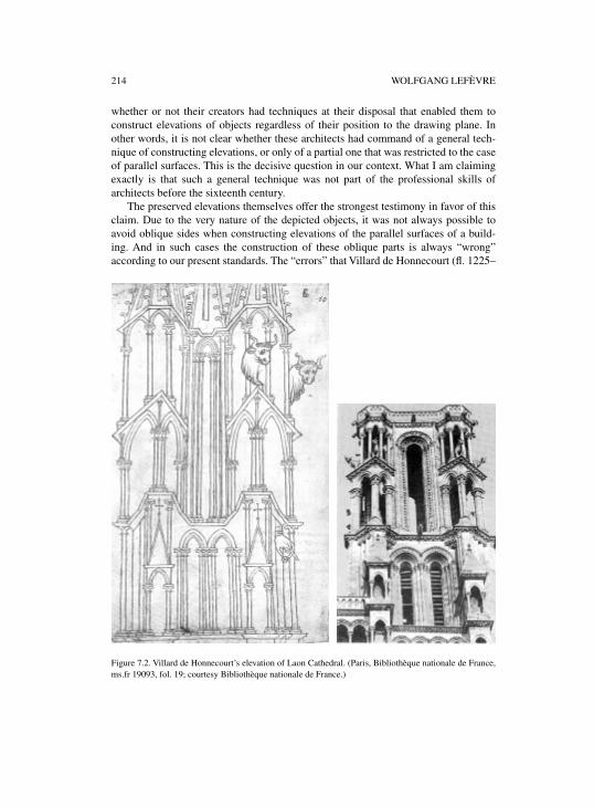
214 WOLFGANG LEFÈVRE
whether or not their creators had techniques at their disposal that enabled them toconstruct elevations of objects regardless of their position to the drawing plane. Inother words, it is not clear whether these architects had command of a general tech-nique of constructing elevations, or only of a partial one that was restricted to the caseof parallel surfaces. This is the decisive question in our context. What I am claimingexactly is that such a general technique was not part of the professional skills ofarchitects before the sixteenth century.
The preserved elevations themselves offer the strongest testimony in favor of thisclaim. Due to the very nature of the depicted objects, it was not always possible toavoid oblique sides when constructing elevations of the parallel surfaces of a build-ing. And in such cases the construction of these oblique parts is always “wrong”according to our present standards. The “errors” that Villard de Honnecourt (fl. 1225–
Figure 7.2. Villard de Honnecourt’s elevation of Laon Cathedral. (Paris, Bibliothèque nationale de France,ms.fr 19093, fol. 19; courtesy Bibliothèque nationale de France.)
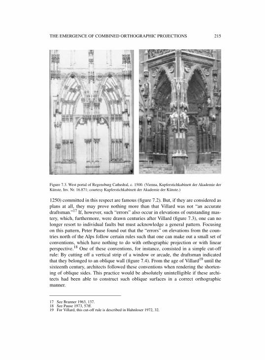
THE EMERGENCE OF COMBINED ORTHOGRAPHIC PROJECTIONS 215
Figure 7.3. West portal of Regensburg Cathedral, c. 1500. (Vienna, Kupferstichkabinett der Akademie derKünste, Inv. Nr. 16.871; courtesy Kupferstichkabinett der Akademie der Künste.)
1250) committed in this respect are famous (figure 7.2). But, if they are considered asplans at all, they may prove nothing more than that Villard was not “an accuratedraftsman.”17 If, however, such “errors” also occur in elevations of outstanding mas-tery, which, furthermore, were drawn centuries after Villard (figure 7.3), one can nolonger resort to individual faults but must acknowledge a general pattern. Focusingon this pattern, Peter Pause found out that the “errors” on elevations from the coun-tries north of the Alps follow certain rules such that one can make out a small set ofconventions, which have nothing to do with orthographic projection or with linearperspective.18 One of these conventions, for instance, consisted in a simple cut-offrule: By cutting off a vertical strip of a window or arcade, the draftsman indicatedthat they belonged to an oblique wall (figure 7.4). From the age of Villard19 until thesixteenth century, architects followed these conventions when rendering the shorten-ing of oblique sides. This practice would be absolutely unintelligible if these archi-tects had been able to construct such oblique surfaces in a correct orthographicmanner.
17 See Branner 1963, 137.18 See Pause 1973, 57ff.19 For Villard, this cut-off rule is described in Hahnloser 1972, 32.
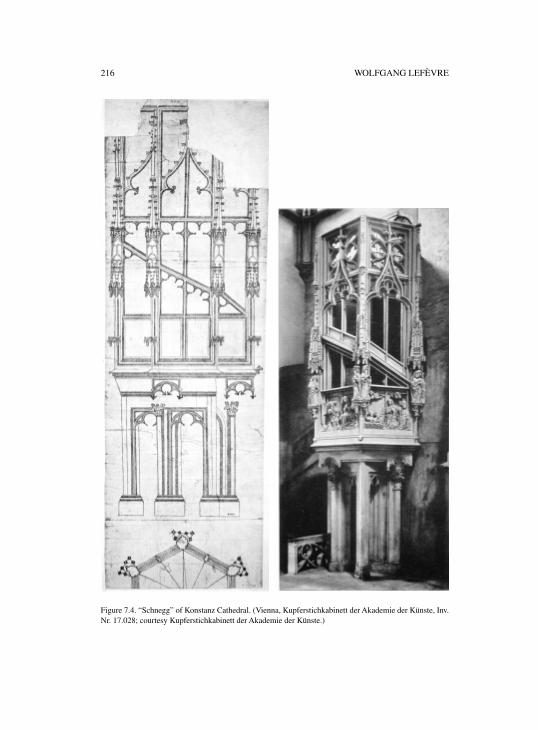
216 WOLFGANG LEFÈVRE
Figure 7.4. “Schnegg” of Konstanz Cathedral. (Vienna, Kupferstichkabinett der Akademie der Künste, Inv.Nr. 17.028; courtesy Kupferstichkabinett der Akademie der Künste.)
THE EMERGENCE OF COMBINED ORTHOGRAPHIC PROJECTIONS 217
The absence of a general technique for constructing elevations of objects, what-ever their position to the drawing plane, could also be shown by pointing out a differ-ent practice that was then common in Italy. Italian architects did not follow theseconventions of their northern colleagues, but used linear perspective when renderingsuch oblique parts of buildings. As Wolfgang Lotz could show for sections, oneencounters no purely orthographic sections in late fifteenth- and early sixteenth-cen-tury Italy. Rather, up to the time of Antonio da Sangallo, architectural sections alwayscombined orthographic with perspective rendering.20 This is all the more remarkablesince these sections prove that a highly developed skill in constructing perspectivedrawings obviously was already remarkably widespread among Italian architects atthe turn of the fifteenth century (figure 7.5). Thus it has the appearance that, at least inItaly, architects were able to construct perspective renderings in an unrestricted man-ner earlier than orthographic elevations. (I will come back to the relations of thesetwo techniques in the last part of this chapter.)
It seems, perhaps, quite unbelievable that men capable of constructing correctperspective drawings21 would not be able to construct all kinds of orthographic eleva-tions. A possible reason why this appears astonishing might be that one underesti-mates the difficulties associated with the task of constructing elevations. And it isindeed probable that this underestimation is a result of the cultural fact that, amongall of the modern techniques of geometric projection that emerged in the Renais-sance, only linear perspective has enjoyed the undivided and continuing attention of abroad audience ranging from art historians over historians of culture, mathematics,and science up to semiotic experts, philosophers, and psychologists. The modern pro-jection techniques of cartographers, astronomers, engineers, and architects, on theother hand, the foundation of which was also laid in this age, are taken to be eithertrivial or only of technical interest for certain experts.
In order to make the difficulties accompanying the construction of an elevation abit more discernible, I should stress that drawing an elevation does not mean portray-ing something, but constructing a representation—a flat model, as Nelson Goodmanmight say.22 This is obvious in the case of elevations for a planned building drawn inthe design process. But even when the task is to record an already existing buildingby means of elevations, such elevations have to be constructed point by point in con-formity with distances and angles taken from the real building using appropriateinstruments. This architectural recording (Bauaufnahme) much more closely resem-bles the mapping of surveyors than the depicting of painters. Vision is suspended in
20 See Lotz 1977. As mentioned above, this also holds for the earliest known Italian elevations, that is, theelevations of the façade of the duomo in Orvieto from the beginning of the fourteenth century, and thefamous elevation of the campanile of Santa Maria del Fiore in Florence from the middle of this century,which is thought to be a copy of an original drawing by Giotto. See for the latter Degenhart et al. (ed.)1968, vol. I.3, table 66 and vol. I.1 89ff. See also Evans 1997, 166f.
21 Apart from a few rare exceptions, we do not actually know how perspective drawings were producedin the fifteenth and in the early sixteenth century. It thus seems well advised in our context to recall aneasily neglected difference between the drawing of perspective pictures and elevations: Whereas theformer could be produced without construction by means of a variety of mechanical-optical devicesthen available, there was (and is) no escape from constructing in the case of the latter.
22 See Goodman 1976, 172f.
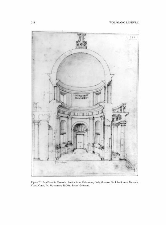
218 WOLFGANG LEFÈVRE
Figure 7.5. San Pietro in Montorio. Section from 16th-century Italy. (London, Sir John Soane’s Museum,Codex Coner, fol. 34; courtesy Sir John Soane’s Museum.
THE EMERGENCE OF COMBINED ORTHOGRAPHIC PROJECTIONS 219
favor of construction, that is, in favor of a complex process of measuring, recordingmeasurements taken, processing these data, and, based on them, tracing the graphicrepresentation according to geometrical rules.
As a means of the designing process, the tracing of elevations seems to be lesscomplex, except for the difficulties of non-trivial geometrical constructions and accu-rate tracing in general, which I ignore here. The desired measurements—for instance,the height and width of the windows or the breadth of the wall between them—can betranslated directly into appropriate geometrical lines and shapes on the plan. But thisis true if, and only if, the plane of the wall or window represented is thought to beparallel to the drawing plane. In all other cases, one has to derive the correct transla-tion from the ground plan. And this derivation is exactly the point where the com-bined views come into play. From a ground plan drawn to the same scale as theelevation and attached to it in the right way, one can “deduce” the correct positions ofthese problematic parts by means of ruler and compass. Moreover, given a list withthe intended heights of all parts in question, one can develop the entire elevation fromthe ground plan. On the other hand, without this technique of combined plans or anysubstitute for it, it is simply impossible to determine the exact position and accuratesize of the representations of those parts that are thought to lie in an oblique plane. Anoctagon like the Florentine baptistery is a case in point (figure 7.6). There is no otherway to determine the distances between the vertical edges of such a simple and regu-lar geometric body on the elevation than that of deriving them from the ground plan.
The extant elevations from before 1500 show, thus, that, apart from two or threeexceptions,23 which confirm rather than challenge the rule and will be discussedbelow in the third part, combined views were not in use before the sixteenth century.This is also confirmed by the telling fact that the famous treatises on architecture ofthe fifteenth century—besides the treatise by Alberti and the letter to Pope Leo Xmentioned above, the Trattato di Architettura by Antonio Averlino, known as Filarete(1400–1469);24 the treatises Architettura ingegneria e arte militare25 and Architetturacivile e militare26 by Francesco di Giorgio Martini (1439–1501); and the drafts onarchitecture of Leonardo da Vinci (1452–1519)27—are absolutely silent on this tech-nique.28 Thus one can assume that combined views were actually unknown in thisage. Not even Cesariano’s Vitruvius edition of 1521 gives any indication of a changein this respect.29 But if combined views had not yet been discovered as a decisivemeans of constructing plans, it is no longer strange that one does not encounter cor-rect elevations of objects with oblique sides before Dürer and Antonio da Sangallo.
23 See Sakarovitch 1998, chap. 1.24 Filarete 1972, English: Filarete 1965.25 Francesco di Giorgio Martini 1967, vol. I.26 Francesco di Giorgio Martini 1967, vol. II.27 Edited in Bruschi et al. (ed.) 1978, 277ff.28 See Sakarovitch 1998, 55ff. With respect to Alberti’s treatise on architecture, see also Thoenes 1993,
569.29 Note that, in Cesariano’s edition, the plate to book I, chapter 2, which displays example drawings for
Vitruvius’ orthographia, also includes drawings that are not orthographic elevations but ratherperspective drawings.
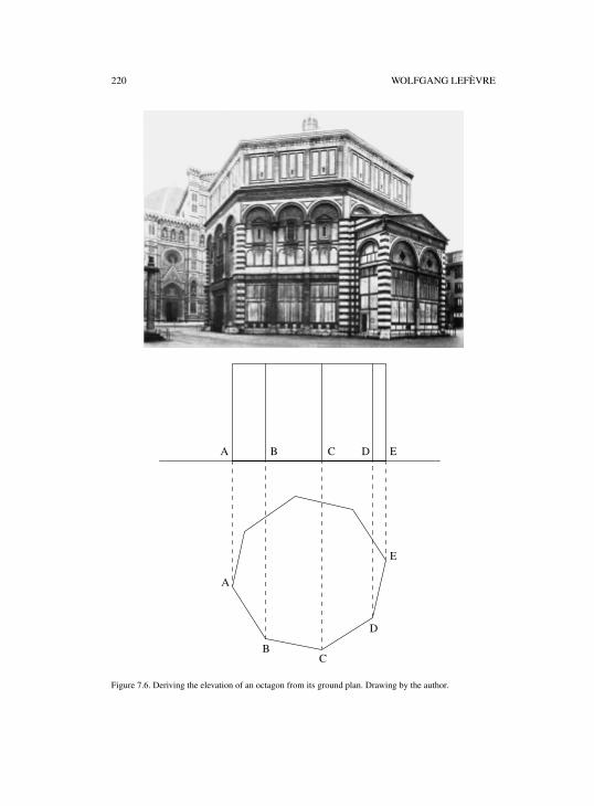
220 WOLFGANG LEFÈVRE
Figure 7.6. Deriving the elevation of an octagon from its ground plan. Drawing by the author.
A B C D E
A
BC
D
E
THE EMERGENCE OF COMBINED ORTHOGRAPHIC PROJECTIONS 221
On the contrary, it would be a miracle if the architects of the age had been able toconstruct correct elevations despite the lack of this technique.
Summing up this first part of this chapter, it can be stated that, in the realm ofarchitecture, the technique of combined views does not occur in fully developed formuntil Antonio da Sangallo and Albrecht Dürer, that is, not before the first decades ofthe sixteenth century. Before going into these achievements and their context and pre-requisites, it might be useful to take a quick glance at the role that plans and drawingsplayed in the process of designing and constructing buildings until the end of the fif-teenth century.
2. PLANS IN ARCHITECTURE UNTIL 1500
Regarding the role of plans for the architectural practice of the Middle Ages and theearly Renaissance, the most striking feature of this practice is probably what can becalled its improvisatorial character. As a rule,30 the architectural features of a plannedbuilding were not fixed in all their aspects and details in advance. Commissioner andarchitect confined themselves to appoint only main features when contracting. Aboveall two reasons seem to be responsible for this practice. First was the custom of post-poning decisions on certain questions to a time when they could be made in light ofthe growing building. Second, and probably more important, was the fact that manyfeatures needed no explicit agreement because they were obvious within the giventradition of construction. All that had to be done was to adapt the canonical rules andconventions of this tradition to local circumstances. And this adaptation was tacitlyincluded in the overall design of the building upon which commissioner and architecthad agreed.
The famous controversial conferences of the Milan cathedral council between1389 and 1401, which are remarkable in so many respects,31 provide a good exampleof the custom of postponing decisions. On the one hand, these conferences testify toongoing revisions of former decisions, that is, to a thorough planning process. On theother hand, however, they testify to a lack of planning in advance that must be incon-ceivable for a contemporary architect. The elementary features of the foundations ofwalls and piles had not only been designed, but actually laid and constructed whenthe question of the height of the naves ignited the controversy. The essential questionof the height of the cathedral was obviously not fixed along with the ground plan.Santa Maria del Fiore, the Florence cathedral, is another case in point. After the orig-inal foundations had been dismissed and replaced by significantly larger ones, anendless process of decisions and revisions of decisions took place with regard to theoverall shape of the cathedral, which the Operai di duomo finally cut off with a some-what iconoclastic act, namely by destroying the competing models.32 However, whatremained unsettled by this finality and engendered the subsequent “drama”33 of the
30 See for the following Müller 1990, 14ff. where the most important literature is discussed.31 See Ackerman 1949.32 See Lepik 1994, 35.33 Saalman 1980, 11.
222 WOLFGANG LEFÈVRE
cupola—not just a decorative spire on top of the crossing, but a weighty, importantpart of the cathedral, structurally as well as aesthetically—was the fundamental ques-tion of whether or not the huge octagonal crossing, which was already built could bevaulted with a cupola of the appointed shape. A similar drama was played out a cen-tury later in Rome when the new San Pietro church was built.34 These three promi-nent examples may represent the innumerable cases up to the beginning of thesixteenth century where the definite design of essential parts of an building was notappointed in advance along with the ground plan, but left to later decisions.
In the light of this improvisatorial building practice, it becomes intelligible whyone encounters only ground plans and elevations or sections of certain parts of abuilding among the preserved architectural plans of the age but, to my knowledge,never a set of plans that determines all main features of a building. The basis of thisastonishingly flexible practice was a traditional framework of rules and conventionsfor how to build a sacral or profane building—a basis, however, which alwaysbecame perilous when, as in the prominent cases mentioned, the designed buildingswent beyond the limits of this tradition. The fact that these rules and conventions35
had guiding functions for architects and craftsmen of the age equivalent to thoseplans have today explains why so many features of a building were not fixed inadvance by means of plans. In Lorenz Lechler’s Unterweisungen of 1516,36 forinstance, one of the few preserved texts that document such rules and conventions,37
one finds several rules, including alternative ones that connect the measures of theessential parts of a church, such as the width of the main nave with its height, thewidth of the arcades, the thickness of piles, walls, buttresses, the measures for theadjacent chorus, and so on. The actual constructed churches were, of course, not mereexecutions of a set of rigid rules and conventions. Rather, these rules formed so flexi-ble a system that decisions were necessary in any case as to which of the countlesspossibilities was to be realized in the situation at hand. And the architect often fur-thermore had to accommodate wishes of his commissioner that were at odds with therules of the art.38 On the basis of this system of rules, however, such decisions andaccommodations could be appointed without a comprehensive set of plans. A groundplan and elevations of some critical parts usually sufficed for this purpose.
It is known that, in the countries north of the Alps, plans were part of the contractsbetween architects and clerical or secular commissioners. Their function was thesame as that of the wooden models in Italy, namely to document the design the con-
34 See Bredekamp 2000.35 See for the following Müller 1990, 78ff.36 A diplomatic copy of the three preserved manuscripts of the booklet can be found in Coenen 1990, 174–
266.37 Apart from Lechler’s booklet, there are five more such practitioners’ texts written by architects for
architects: 1)Von des Chores Maß und Gerechtigkeit of about 1500, of which only an incompletenineteenth-century edition exists but neither the original nor contemporary copies (see Coenen 1990,25); 2) the so-called Wiener Werkmeisterbuch from the fifteenth century; 3) Matthäus Roriczer’sBüchlein von der Fialen Gerechtigkeit of 1486, and 4) his Geometria Deutsch, written slightly later; 5)Hans Schmuttermayer’s Fialenbüchlein of the 1480s. Coenen 1990 provides diplomatic copies of all ofthese texts. Shelby 1977 provides an modernized edition and English translation of the two booklets byRoriczer and the one by Schmuttermayer.
38 See, for instance, Lechler’s complaints: Coenen 1990, pp. 179, 233, 262.
THE EMERGENCE OF COMBINED ORTHOGRAPHIC PROJECTIONS 223
tracting party had agreed upon.39 But it is not known how sketchy or sophisticatedthese plans were. Some scholars regard the bulk of the preserved plans, and in partic-ular the splendid elevations, as illustration drawings addressed to commissioners.40
The reason for this ascription is mainly that these plans look too elaborated for draftsand too inaccurate for working drawings (Werkrisse), that is, plans that were used inthe construction process.41 This leads to the question of exactly what functions planshad in the process of designing on the one hand, and for the construction process onthe other, given the flexible character of the architectural practice outlined above.
Beginning with the function of plans in the architectural design process of theMiddle Ages and the early Renaissance, there is little accord among the experts.Since no single plan is known that without any doubt served the purpose of design,and the same holds for sketches before Leonardo, one can only speculate about thegraphic means that the architects of the age used when designing a sacral or profanebuilding. It thus comes as no surprise that one meets the whole spectrum of possibleassumptions in the literature, ranging from designing without any kind of plans42
over sophisticated geometrical design procedures43 up to designing with all kinds oforthographic plans.44 One point, however, seems to be clear: Plans and other graphicrepresentations were no means of reflection or thought experiments regarding thestatic of the planned building. Leonardo’s sketches in the Codex Madrid are absoluteexceptions. Another point seems to be at least very likely, namely the use of grids fordesigning ground plans. The famous plan of the Abbey of St. Gall from the ninth cen-tury obviously uses this grid technique, which can be traced back to ancient Egypt.There is no reason to assume that this suitable graphic technique went lost in thecourse of the Middle Ages.
With respect to the function of plans in the construction process, one should dis-tinguish between reduced plans that are scaled down and full-size plans that are con-structed to full scale (1:1). It goes without saying that, in contrast to full-size plans,reduced plans do not yield any information that can be picked up mechanically bymeans of compasses or comparable instruments. Rather, one first has to process theinformation of these plans through both arithmetical and geometrical proceduresbefore measures and shapes can be transferred to the building materials. According tothe literature, it is still an open question whether or not the few reduced plans we havecan be taken to be accurately scaled plans, and therefore to be real working draw-ings.45 But even if one regards some or all of them as working drawings, it has theappearance that their use was not widespread,46 probably above all because the
39 See, for instance, Kletzl 1939, 4.40 See, for instance, Saalman 1959, 103; see, on the other hand, Lepik 1994, 15.41 For the term “working drawing,” see French 1947, 307, for Werkrisse, see Kletzl 1939, 4ff.42 See, for instance, Booz 1956, 68f.43 Speculations about geometrical design procedures for the entire building, called Proportionierungs-
systeme, go back to the Neugothik of the nineteenth century; for a principal critique see Hecht 1997;see also Müller 1990, 39ff.
44 See, for instance, Lepik 1994, 15.45 See Booz 1956, 75ff., Hecht 1997, 361ff., Lepik 1994, 15f. I do not raise here the related question of
reduced plans with dimensions and measures marked on them.46 See for the following Müller 1990, 15ff.
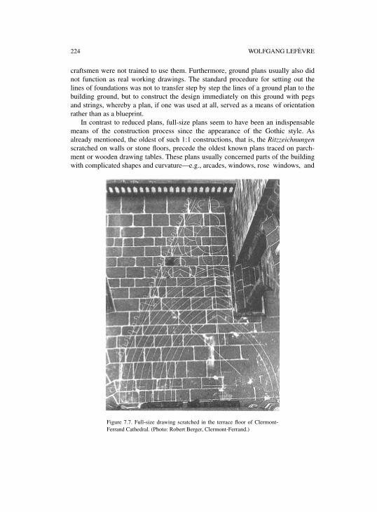
224 WOLFGANG LEFÈVRE
craftsmen were not trained to use them. Furthermore, ground plans usually also didnot function as real working drawings. The standard procedure for setting out thelines of foundations was not to transfer step by step the lines of a ground plan to thebuilding ground, but to construct the design immediately on this ground with pegsand strings, whereby a plan, if one was used at all, served as a means of orientationrather than as a blueprint.
In contrast to reduced plans, full-size plans seem to have been an indispensablemeans of the construction process since the appearance of the Gothic style. Asalready mentioned, the oldest of such 1:1 constructions, that is, the Ritzzeichnungenscratched on walls or stone floors, precede the oldest known plans traced on parch-ment or wooden drawing tables. These plans usually concerned parts of the buildingwith complicated shapes and curvature—e.g., arcades, windows, rose windows, and
Figure 7.7. Full-size drawing scratched in the terrace floor of Clermont-Ferrand Cathedral. (Photo: Robert Berger, Clermont-Ferrand.)
THE EMERGENCE OF COMBINED ORTHOGRAPHIC PROJECTIONS 225
so on.47 They often more resemble geometric constructions from which the form of acertain part of, say, a window can be taken mechanically, than they do plans of thiswindow (figure 7.7). These constructions are thus closely related to other meansemployed in building practice for the creation of complicated shapes, ranging fromspecial kinds of diagrams for the derivation of the rib systems of complicated vaults(Bogenaustragung)48 to templates, which came into use in mediaeval architecturealong with a standardization of stone-dressing at the beginning of the thirteenth cen-tury.49 These geometric aids of the construction process, most of the full-scale Ritzze-ichnungen included, probably do not immediately come to mind when plans arementioned and, indeed, can hardly be called architectural plans in the usual sense ofthe term. They are, however, reminiscent of the fact that such plans, if used in theconstruction process, are just one of many geometric means that support the creationof the desired shapes of a building. They point furthermore to geometrical practicesof craftsmen that may be of interest with respect to the roots of the combined viewstechnique as developed by Dürer.
Yet, before coming to the emergence of this technique, this concise survey of theuse of plans in architecture before 1500 should be summed up by stressing that thearchitects and craftsmen of the age could obviously do very well without a generalmethod of deriving elevations from ground plans. As Schofield put it for Italy:
There can be little doubt that the orthogonal was used in the fifteenth century in the sameway for the same type of architectural features, i.e., flat exteriors and flat interiors anddetails, but would not have been used for general views of interiors or exteriors wherethere were large-scale features that projected or receded from the front plane. Indeed, inthe case of large-scale architectural units, it is to be doubted that a reasonably accurate,or even moderately inaccurate elevation drawing in perspective accompanied by dimen-sions (either drawn-on or on list) was any less useful than a fully marked-up orthogonal.The reason for thinking this is simply that a careful perspective drawing, especially onewith dimensions marked on it, was better able than an orthogonal to provide preciseinformation about details, large or small, that receded or projected from the frontal plane.This is confirmed by the practice of architects drawing in the early sixteenth century.50
Whether actually “better able” or only equally well, the architects of the age had inany case all means at their disposal needed to fulfill their tasks. Thus, in this investi-gation of the emergence of the combined view technique, one has to start from thefact that, obviously, no urgent needs of the construction practice stimulated Dürer orda Sangallo to create this new technique. Given this situation, it also comes as no sur-prise that this new method was only hesitantly adopted by sixteenth-century archi-tects and became a standard technique of the art not before the seventeenth century.
47 For the full-scale Ritzzeichnungen, see Schoeller 1989 and 1980, as well as Davis 2002.48 For such plans, see Müller 1990, 152ff.49 See Müller 1990, 126ff. and Kimpel 1983. See also Shelby 1971.50 Schofield 1991, 129.
226 WOLFGANG LEFÈVRE
3. THE GENERAL METHOD OF CONSTRUCTING ELEVATIONS
From the perspective of the history of mathematics, the new method in question isnothing but descriptive geometry in an early—actually in its first—but neverthelessmanifest stage of development. However, in this first stage, this branch of mathemat-ics looks not at all like what one expects from a scientific field. First, Dürer and daSangallo were no mathematicians, notwithstanding the fact that they had obviouslysome mathematical knowledge and were in touch with men who can be regarded asmathematicians.51 Second and more importantly, they established no theory. Da San-gallo did not publish a single treatise,52 and Dürer’s treatises do not argue for the newmethod of constructing plans but give, among many other things, practical step-by-step instructions on how to derive certain elevations from ground plans. Particularlyhis Underweysung der Messung from 1525,53 the most important text in this context,looks like a book of recipes rather than a theoretical text. It is, thus, not sufficient tostate that the beginnings of descriptive geometry were imbedded in the practice ofartists. Rather, one has to realize that descriptive geometry was one of the techniquesemployed in this practice at the time and nothing else. Such practitioners’ knowledgetook on a scientific character only later, beginning at the turn of the sixteenth century,when men with scientific interests discovered its importance and reshaped it in theo-retical frameworks which, at the same time, detached it from its origins.54 The sub-ject matter here is not descriptive geometry as it emerged through this appropriationand transformation by savants, but descriptive geometry as it was in its beginnings,that is, as practitioners’ knowledge.55
In Dürer’s treatises, one encounters for the first time a construction of an elevationby combined views in the first book of the Underweysung der Messung. The topic ofthis first book is techniques of constructing several shapes and curves by means ofruler and compasses. After a few pages with more or less trivial drawing tasks leadingto the construction of several spirals (Schnecken—snails), Dürer almost casually goeson to elevations of helices, that is, of three-dimensional spirals. It is important to notethat he himself does not use terms like projection or elevation in this passage as
51 For Dürer see, for instance, Steck 1948, 6 and 85ff. (note 8); for da Sangallo, see, for instance, Frommel1994b, 3.
52 It is known, however, that da Sangallo considered publishing a commented edition of Vitruvius—seeFrommel 1994b, 36.
53 Albrecht Dürer, Underweysung der Messung / mit dem zirckel undrichtscheyt / in Linien ebnen unndgantzen corporen / durch Albrecht Dürer zusamen getzogen / und zu nutz allen kunstlieb habenden mitzu gehörigen figuren / in truck gebracht / im jar. MDXXV, published in Nuremberg. For a modernfacsimile edition see, for instance, Dürer 1983. There exists no modern German edition of this treatisethat would comply with present standards of critical editions. A facsimile edition with an Englishtranslation was edited by Walter L. Strauss—see Dürer 1977. Jeanne Peiffer edited a French editionalong with an excellent introduction and valuable appendixes—see Dürer 1995.
54 For Dürer, see Peiffer 1995, 123.55 This is the reason why Dürer and da Sangallo are not considered mathematicians in this chapter, which
may appear strange in several respects. This categorization rests neither on a disdain of theirmathematical abilities nor on their social standing—which contemporary mathematician enjoyed ahigher standing than da Sangallo? The decisive point in our context is that these men developed andpractised the new projective geometry as a technique of craftsmen and not as a doctrine. Furthermore,this technique cannot be taken to be an applied science. Rather, the later science of projective geometryemerged from this technique.
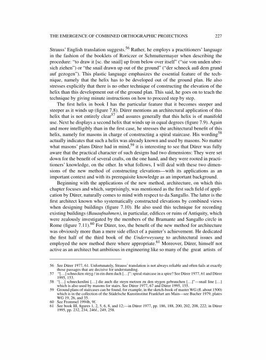
THE EMERGENCE OF COMBINED ORTHOGRAPHIC PROJECTIONS 227
Strauss’ English translation suggests.56 Rather, he employs a practitioners’ languagein the fashion of the booklets of Roriczer or Schmuttermayer when describing theprocedure: “to draw it [sc. the snail] up from below over itself” (“sie von unden uber-sich ziehen”) or “the snail drawn up out of the ground” (“der schneck auß dem grundauf gezogen”). This plastic language emphasizes the essential feature of the tech-nique, namely that the helix has to be developed out of the ground plan. He alsostresses explicitly that there is no other technique of constructing the elevation of thehelix than this development out of the ground plan. This said, he goes on to teach thetechnique by giving minute instructions on how to proceed step by step.
The first helix in book I has the particular feature that it becomes steeper andsteeper as it winds up (figure 7.8). Dürer mentions an architectural application of thishelix that is not entirely clear57 and assures generally that this helix is of manifolduse. Next he displays a second helix that winds up in equal degrees (figure 7.9). Againand more intelligibly than in the first case, he stresses the architectural benefit of thishelix, namely for masons in charge of constructing a spiral staircase. His wording58
actually indicates that such a helix was already known and used by masons. No matterwhat masons’ plans Dürer had in mind,59 it is interesting to see that Dürer was fullyaware that the practical character of such designs had two dimensions: They were setdown for the benefit of several crafts, on the one hand, and they were rooted in practi-tioners’ knowledge, on the other. In what follows, I will deal with these two dimen-sions of the new method of constructing elevations—with its applications as animportant context and with its prerequisite knowledge as an important background.
Beginning with the applications of the new method, architecture, on which thischapter focuses and which, surprisingly, was mentioned as the first such field of appli-cation by Dürer, naturally comes to mind with respect to da Sangallo. The latter is thefirst architect known who systematically constructed elevations by combined viewswhen designing buildings (figure 7.10). He also used this technique for recordingexisting buildings (Bauaufnahmen), in particular, edifices or ruins of Antiquity, whichwere zealously investigated by the members of the Bramante and Sangallo circle inRome (figure 7.11).60 For Dürer, too, the benefit of the new method for architecturewas obviously more than a mere side effect of a painter’s achievement. He dedicatedthe first half of the third book of the Underweysung to architectural issues andemployed the new method there where appropriate.61 Moreover, Dürer, himself notactive as an architect but ambitious in engineering like so many of the great artists of
56 See Dürer 1977, 61. Unfortunately, Strauss’ translation is not always reliable and often fails at exactlythose passages that are decisive for understanding.
57 “[…] schnecken steyg / in ein durn dach […]”: spiral staircase in a spire? See Dürer 1977, 61 and Dürer1995, 153.
58 “[…] schneckenlini […] die auch die steyn metzen zu den stygen gebrauchen […]”—snail line […]which is also used by masons for stairs. See Dürer 1977, 67 and Dürer 1995, 155.
59 Ground plans of staircases can be found, for example, in the sketch-book of master WG (fl. about 1500)which is in the collection of the Städelsche Kunstinstitut Frankfurt am Main—see Bucher 1979, platesWG 19, 26, and 35.
60 See Frommel 1994b, 9f.61 See book III, figures 1, 2, 5, 6, 8, and 12;—in Dürer 1977, pp. 186, 188, 200, 202, 208, 222; in Dürer
1995, pp. 232, 234, 246f., 249, 258.
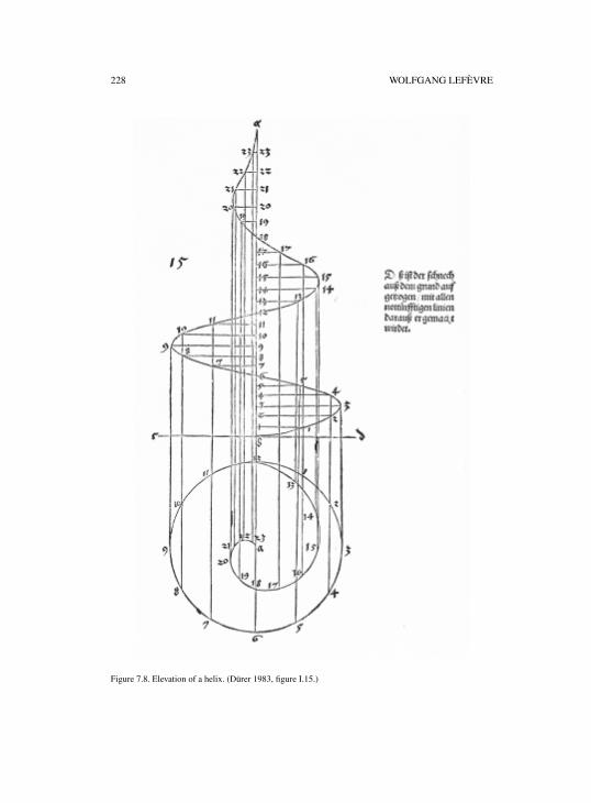
228 WOLFGANG LEFÈVRE
Figure 7.8. Elevation of a helix. (Dürer 1983, figure I.15.)
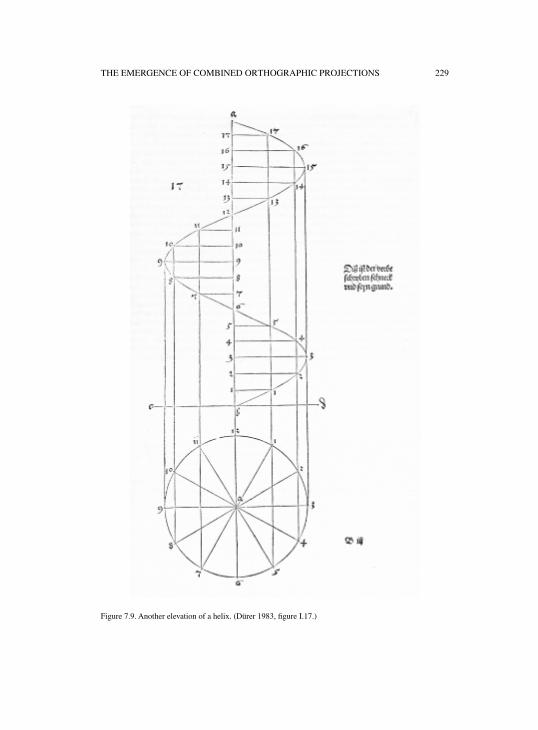
THE EMERGENCE OF COMBINED ORTHOGRAPHIC PROJECTIONS 229
Figure 7.9. Another elevation of a helix. (Dürer 1983, figure I.17.)
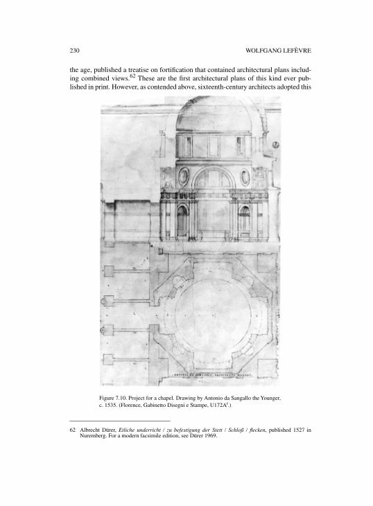
230 WOLFGANG LEFÈVRE
the age, published a treatise on fortification that contained architectural plans includ-ing combined views.62 These are the first architectural plans of this kind ever pub-lished in print. However, as contended above, sixteenth-century architects adopted this
62 Albrecht Dürer, Etliche underricht / zu befestigung der Stett / Schloß / flecken, published 1527 inNuremberg. For a modern facsimile edition, see Dürer 1969.
Figure 7.10. Project for a chapel. Drawing by Antonio da Sangallo the Younger,c. 1535. (Florence, Gabinetto Disegni e Stampe, U172Ar.)
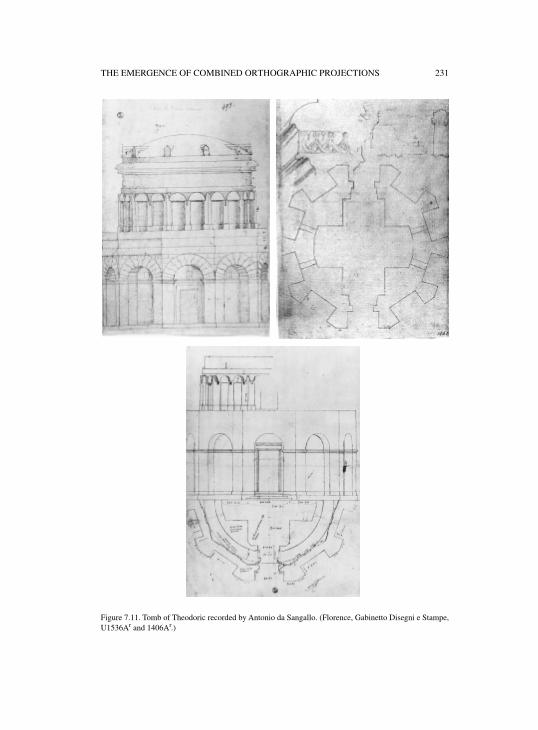
THE EMERGENCE OF COMBINED ORTHOGRAPHIC PROJECTIONS 231
Figure 7.11. Tomb of Theodoric recorded by Antonio da Sangallo. (Florence, Gabinetto Disegni e Stampe,U1536Ar and 1406Ar.)
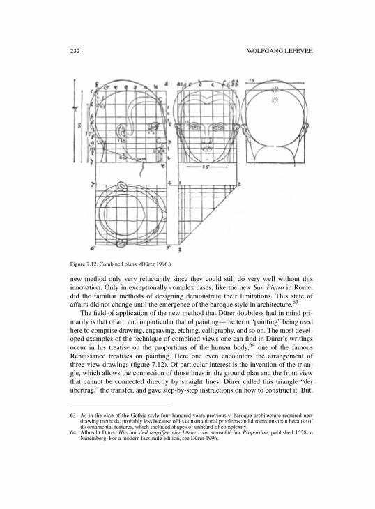
232 WOLFGANG LEFÈVRE
Figure 7.12. Combined plans. (Dürer 1996.)
new method only very reluctantly since they could still do very well without thisinnovation. Only in exceptionally complex cases, like the new San Pietro in Rome,did the familiar methods of designing demonstrate their limitations. This state ofaffairs did not change until the emergence of the baroque style in architecture.63
The field of application of the new method that Dürer doubtless had in mind pri-marily is that of art, and in particular that of painting—the term “painting” being usedhere to comprise drawing, engraving, etching, calligraphy, and so on. The most devel-oped examples of the technique of combined views one can find in Dürer’s writingsoccur in his treatise on the proportions of the human body,64 one of the famousRenaissance treatises on painting. Here one even encounters the arrangement ofthree-view drawings (figure 7.12). Of particular interest is the invention of the trian-gle, which allows the connection of those lines in the ground plan and the front viewthat cannot be connected directly by straight lines. Dürer called this triangle “derubertrag,” the transfer, and gave step-by-step instructions on how to construct it. But,
63 As in the case of the Gothic style four hundred years previously, baroque architecture required newdrawing methods, probably less because of its constructional problems and dimensions than because ofits ornamental features, which included shapes of unheard-of complexity.
64 Albrecht Dürer, Hierinn sind begriffen vier bücher von menschlicher Proportion, published 1528 inNuremberg. For a modern facsimile edition, see Dürer 1996.
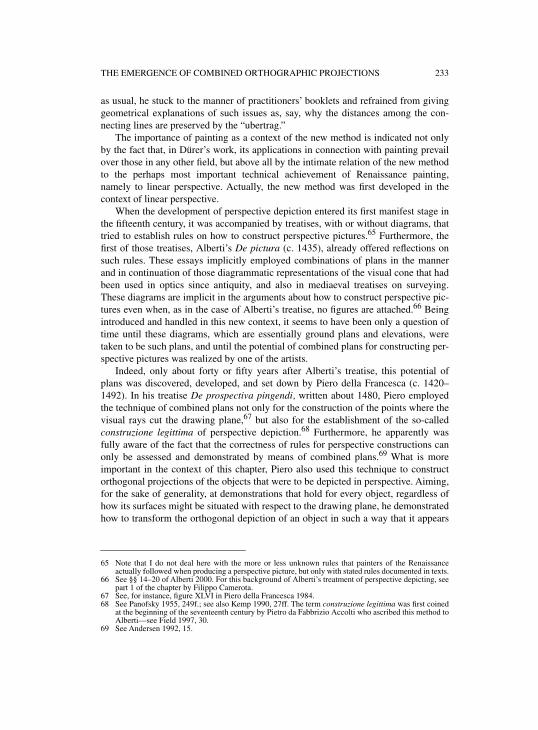
THE EMERGENCE OF COMBINED ORTHOGRAPHIC PROJECTIONS 233
as usual, he stuck to the manner of practitioners’ booklets and refrained from givinggeometrical explanations of such issues as, say, why the distances among the con-necting lines are preserved by the “ubertrag.”
The importance of painting as a context of the new method is indicated not onlyby the fact that, in Dürer’s work, its applications in connection with painting prevailover those in any other field, but above all by the intimate relation of the new methodto the perhaps most important technical achievement of Renaissance painting,namely to linear perspective. Actually, the new method was first developed in thecontext of linear perspective.
When the development of perspective depiction entered its first manifest stage inthe fifteenth century, it was accompanied by treatises, with or without diagrams, thattried to establish rules on how to construct perspective pictures.65 Furthermore, thefirst of those treatises, Alberti’s De pictura (c. 1435), already offered reflections onsuch rules. These essays implicitly employed combinations of plans in the mannerand in continuation of those diagrammatic representations of the visual cone that hadbeen used in optics since antiquity, and also in mediaeval treatises on surveying.These diagrams are implicit in the arguments about how to construct perspective pic-tures even when, as in the case of Alberti’s treatise, no figures are attached.66 Beingintroduced and handled in this new context, it seems to have been only a question oftime until these diagrams, which are essentially ground plans and elevations, weretaken to be such plans, and until the potential of combined plans for constructing per-spective pictures was realized by one of the artists.
Indeed, only about forty or fifty years after Alberti’s treatise, this potential ofplans was discovered, developed, and set down by Piero della Francesca (c. 1420–1492). In his treatise De prospectiva pingendi, written about 1480, Piero employedthe technique of combined plans not only for the construction of the points where thevisual rays cut the drawing plane,67 but also for the establishment of the so-calledconstruzione legittima of perspective depiction.68 Furthermore, he apparently wasfully aware of the fact that the correctness of rules for perspective constructions canonly be assessed and demonstrated by means of combined plans.69 What is moreimportant in the context of this chapter, Piero also used this technique to constructorthogonal projections of the objects that were to be depicted in perspective. Aiming,for the sake of generality, at demonstrations that hold for every object, regardless ofhow its surfaces might be situated with respect to the drawing plane, he demonstratedhow to transform the orthogonal depiction of an object in such a way that it appears
65 Note that I do not deal here with the more or less unknown rules that painters of the Renaissanceactually followed when producing a perspective picture, but only with stated rules documented in texts.
66 See §§ 14–20 of Alberti 2000. For this background of Alberti’s treatment of perspective depicting, seepart 1 of the chapter by Filippo Camerota.
67 See, for instance, figure XLVI in Piero della Francesca 1984.68 See Panofsky 1955, 249f.; see also Kemp 1990, 27ff. The term construzione legittima was first coined
at the beginning of the seventeenth century by Pietro da Fabbrizio Accolti who ascribed this method toAlberti—see Field 1997, 30.
69 See Andersen 1992, 15.
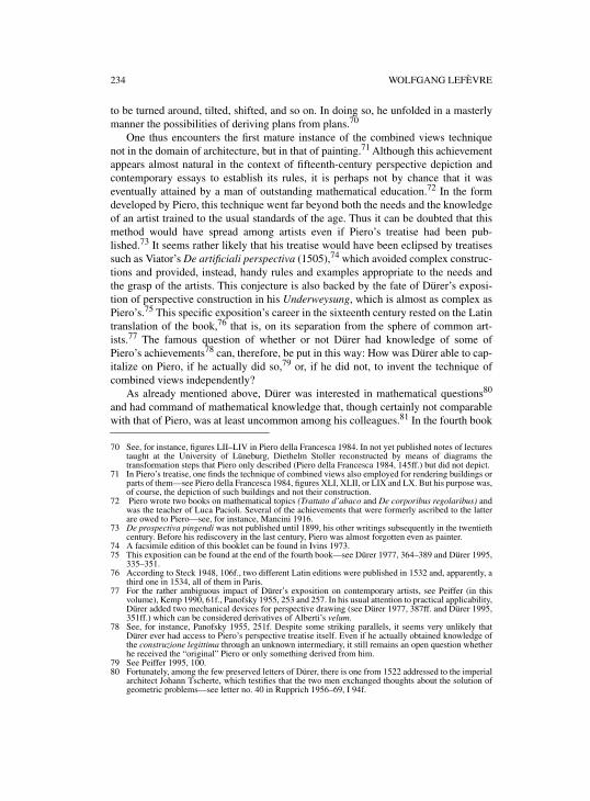
234 WOLFGANG LEFÈVRE
to be turned around, tilted, shifted, and so on. In doing so, he unfolded in a masterlymanner the possibilities of deriving plans from plans.70
One thus encounters the first mature instance of the combined views techniquenot in the domain of architecture, but in that of painting.71 Although this achievementappears almost natural in the context of fifteenth-century perspective depiction andcontemporary essays to establish its rules, it is perhaps not by chance that it waseventually attained by a man of outstanding mathematical education.72 In the formdeveloped by Piero, this technique went far beyond both the needs and the knowledgeof an artist trained to the usual standards of the age. Thus it can be doubted that thismethod would have spread among artists even if Piero’s treatise had been pub-lished.73 It seems rather likely that his treatise would have been eclipsed by treatisessuch as Viator’s De artificiali perspectiva (1505),74 which avoided complex construc-tions and provided, instead, handy rules and examples appropriate to the needs andthe grasp of the artists. This conjecture is also backed by the fate of Dürer’s exposi-tion of perspective construction in his Underweysung, which is almost as complex asPiero’s.75 This specific exposition’s career in the sixteenth century rested on the Latintranslation of the book,76 that is, on its separation from the sphere of common art-ists.77 The famous question of whether or not Dürer had knowledge of some ofPiero’s achievements78 can, therefore, be put in this way: How was Dürer able to cap-italize on Piero, if he actually did so,79 or, if he did not, to invent the technique ofcombined views independently?
As already mentioned above, Dürer was interested in mathematical questions80
and had command of mathematical knowledge that, though certainly not comparablewith that of Piero, was at least uncommon among his colleagues.81 In the fourth book
70 See, for instance, figures LII–LIV in Piero della Francesca 1984. In not yet published notes of lecturestaught at the University of Lüneburg, Diethelm Stoller reconstructed by means of diagrams thetransformation steps that Piero only described (Piero della Francesca 1984, 145ff.) but did not depict.
71 In Piero’s treatise, one finds the technique of combined views also employed for rendering buildings orparts of them—see Piero della Francesca 1984, figures XLI, XLII, or LIX and LX. But his purpose was,of course, the depiction of such buildings and not their construction.
72 Piero wrote two books on mathematical topics (Trattato d’abaco and De corporibus regolaribus) andwas the teacher of Luca Pacioli. Several of the achievements that were formerly ascribed to the latterare owed to Piero—see, for instance, Mancini 1916.
73 De prospectiva pingendi was not published until 1899, his other writings subsequently in the twentiethcentury. Before his rediscovery in the last century, Piero was almost forgotten even as painter.
74 A facsimile edition of this booklet can be found in Ivins 1973.75 This exposition can be found at the end of the fourth book—see Dürer 1977, 364–389 and Dürer 1995,
335–351.76 According to Steck 1948, 106f., two different Latin editions were published in 1532 and, apparently, a
third one in 1534, all of them in Paris.77 For the rather ambiguous impact of Dürer’s exposition on contemporary artists, see Peiffer (in this
volume), Kemp 1990, 61f., Panofsky 1955, 253 and 257. In his usual attention to practical applicability,Dürer added two mechanical devices for perspective drawing (see Dürer 1977, 387ff. and Dürer 1995,351ff.) which can be considered derivatives of Alberti’s velum.
78 See, for instance, Panofsky 1955, 251f. Despite some striking parallels, it seems very unlikely thatDürer ever had access to Piero’s perspective treatise itself. Even if he actually obtained knowledge ofthe construzione legittima through an unknown intermediary, it still remains an open question whetherhe received the “original” Piero or only something derived from him.
79 See Peiffer 1995, 100.80 Fortunately, among the few preserved letters of Dürer, there is one from 1522 addressed to the imperial
architect Johann Tscherte, which testifies that the two men exchanged thoughts about the solution ofgeometric problems—see letter no. 40 in Rupprich 1956–69, I 94f.
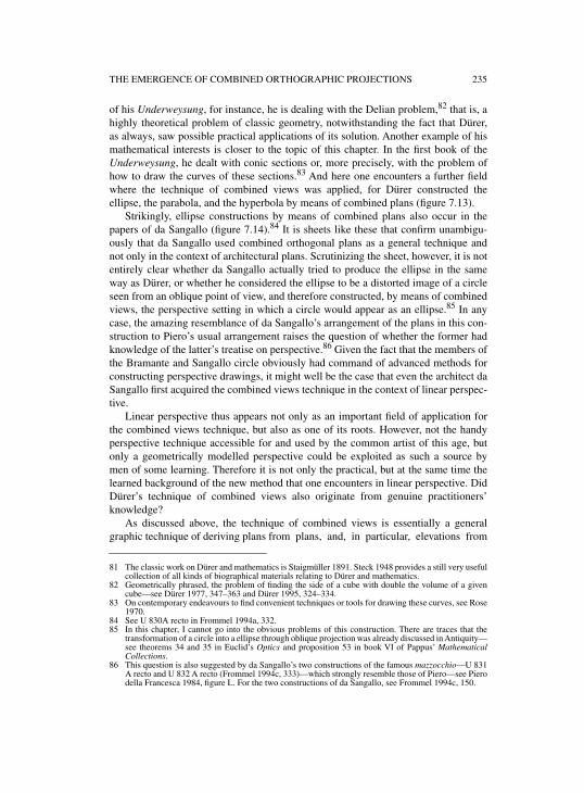
THE EMERGENCE OF COMBINED ORTHOGRAPHIC PROJECTIONS 235
of his Underweysung, for instance, he is dealing with the Delian problem,82 that is, ahighly theoretical problem of classic geometry, notwithstanding the fact that Dürer,as always, saw possible practical applications of its solution. Another example of hismathematical interests is closer to the topic of this chapter. In the first book of theUnderweysung, he dealt with conic sections or, more precisely, with the problem ofhow to draw the curves of these sections.83 And here one encounters a further fieldwhere the technique of combined views was applied, for Dürer constructed theellipse, the parabola, and the hyperbola by means of combined plans (figure 7.13).
Strikingly, ellipse constructions by means of combined plans also occur in thepapers of da Sangallo (figure 7.14).84 It is sheets like these that confirm unambigu-ously that da Sangallo used combined orthogonal plans as a general technique andnot only in the context of architectural plans. Scrutinizing the sheet, however, it is notentirely clear whether da Sangallo actually tried to produce the ellipse in the sameway as Dürer, or whether he considered the ellipse to be a distorted image of a circleseen from an oblique point of view, and therefore constructed, by means of combinedviews, the perspective setting in which a circle would appear as an ellipse.85 In anycase, the amazing resemblance of da Sangallo’s arrangement of the plans in this con-struction to Piero’s usual arrangement raises the question of whether the former hadknowledge of the latter’s treatise on perspective.86 Given the fact that the members ofthe Bramante and Sangallo circle obviously had command of advanced methods forconstructing perspective drawings, it might well be the case that even the architect daSangallo first acquired the combined views technique in the context of linear perspec-tive.
Linear perspective thus appears not only as an important field of application forthe combined views technique, but also as one of its roots. However, not the handyperspective technique accessible for and used by the common artist of this age, butonly a geometrically modelled perspective could be exploited as such a source bymen of some learning. Therefore it is not only the practical, but at the same time thelearned background of the new method that one encounters in linear perspective. DidDürer’s technique of combined views also originate from genuine practitioners’knowledge?
As discussed above, the technique of combined views is essentially a generalgraphic technique of deriving plans from plans, and, in particular, elevations from
81 The classic work on Dürer and mathematics is Staigmüller 1891. Steck 1948 provides a still very usefulcollection of all kinds of biographical materials relating to Dürer and mathematics.
82 Geometrically phrased, the problem of finding the side of a cube with double the volume of a givencube—see Dürer 1977, 347–363 and Dürer 1995, 324–334.
83 On contemporary endeavours to find convenient techniques or tools for drawing these curves, see Rose1970.
84 See U 830A recto in Frommel 1994a, 332.85 In this chapter, I cannot go into the obvious problems of this construction. There are traces that the
transformation of a circle into a ellipse through oblique projection was already discussed in Antiquity—see theorems 34 and 35 in Euclid’s Optics and proposition 53 in book VI of Pappus’ MathematicalCollections.
86 This question is also suggested by da Sangallo’s two constructions of the famous mazzocchio—U 831A recto and U 832 A recto (Frommel 1994c, 333)—which strongly resemble those of Piero—see Pierodella Francesca 1984, figure L. For the two constructions of da Sangallo, see Frommel 1994c, 150.
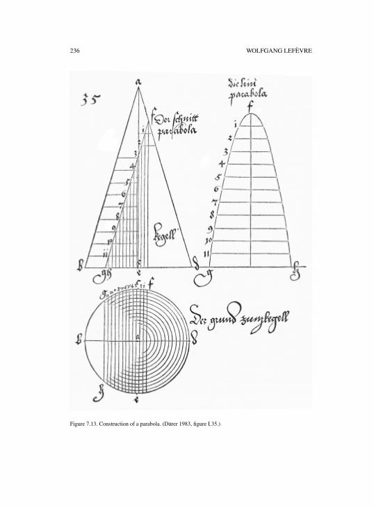
236 WOLFGANG LEFÈVRE
Figure 7.13. Construction of a parabola. (Dürer 1983, figure I.35.)
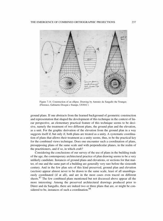
THE EMERGENCE OF COMBINED ORTHOGRAPHIC PROJECTIONS 237
ground plans. If one abstracts from the learned background of geometric constructionand representation that shaped the development of this technique in the context of lin-ear perspective, an elementary practical feature of this technique seems to be deci-sive, namely the treatment of two different plans, the ground plan and the elevation,as a unit. For the graphic derivation of the elevation from the ground plan in a waysuggests itself if, but only if, both plans are treated as a unity. A systematic coordina-tion of plans that allows their treatment as a unity seems, thus, to be the practical keyfor the combined views technique. Does one encounter such a coordination of plans,presupposing plans of the same scale and with perpendicular planes, in the realm ofthe practitioners, and if so, in which craft?
Considering the conclusions of our survey of the use of plans in the building tradeof the age, the contemporary architectural practice of plan drawing seems to be a veryunlikely candidate. Instances of ground plans and elevations, or sections for that mat-ter, of one and the same part of a building are generally very rare before the sixteenthcentury. And in the few plan sets of this kind preserved, ground plan and elevation(section) appear almost never to be drawn to the same scale, least of all unambigu-ously coordinated (if at all), and are in the most cases even traced on differentsheets.87 The few combined plans mentioned but not discussed above appear all themore interesting: Among the preserved architectural drawings produced prior toDürer and da Sangallo, there are indeed two or three plans that are, or might be con-sidered to be, instances of such a coordination.88
Figure 7.14. Construction of an ellipse. Drawing by Antonio da Sangallo the Younger.(Florence, Gabinetto Disegni e Stampe, U830Ar.)
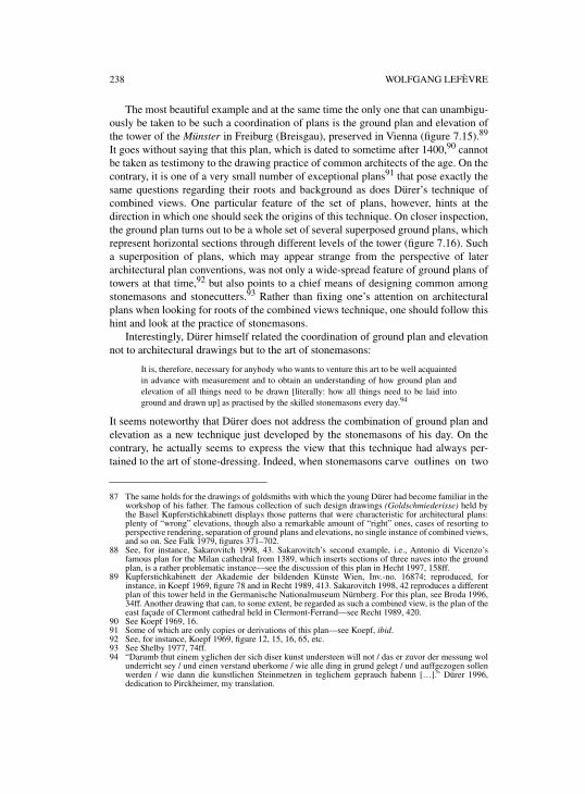
238 WOLFGANG LEFÈVRE
The most beautiful example and at the same time the only one that can unambigu-ously be taken to be such a coordination of plans is the ground plan and elevation ofthe tower of the Münster in Freiburg (Breisgau), preserved in Vienna (figure 7.15).89
It goes without saying that this plan, which is dated to sometime after 1400,90 cannotbe taken as testimony to the drawing practice of common architects of the age. On thecontrary, it is one of a very small number of exceptional plans91 that pose exactly thesame questions regarding their roots and background as does Dürer’s technique ofcombined views. One particular feature of the set of plans, however, hints at thedirection in which one should seek the origins of this technique. On closer inspection,the ground plan turns out to be a whole set of several superposed ground plans, whichrepresent horizontal sections through different levels of the tower (figure 7.16). Sucha superposition of plans, which may appear strange from the perspective of laterarchitectural plan conventions, was not only a wide-spread feature of ground plans oftowers at that time,92 but also points to a chief means of designing common amongstonemasons and stonecutters.93 Rather than fixing one’s attention on architecturalplans when looking for roots of the combined views technique, one should follow thishint and look at the practice of stonemasons.
Interestingly, Dürer himself related the coordination of ground plan and elevationnot to architectural drawings but to the art of stonemasons:
It is, therefore, necessary for anybody who wants to venture this art to be well acquaintedin advance with measurement and to obtain an understanding of how ground plan andelevation of all things need to be drawn [literally: how all things need to be laid intoground and drawn up] as practised by the skilled stonemasons every day.94
It seems noteworthy that Dürer does not address the combination of ground plan andelevation as a new technique just developed by the stonemasons of his day. On thecontrary, he actually seems to express the view that this technique had always per-tained to the art of stone-dressing. Indeed, when stonemasons carve outlines on two
87 The same holds for the drawings of goldsmiths with which the young Dürer had become familiar in theworkshop of his father. The famous collection of such design drawings (Goldschmiederisse) held bythe Basel Kupferstichkabinett displays those patterns that were characteristic for architectural plans:plenty of “wrong” elevations, though also a remarkable amount of “right” ones, cases of resorting toperspective rendering, separation of ground plans and elevations, no single instance of combined views,and so on. See Falk 1979, figures 371–702.
88 See, for instance, Sakarovitch 1998, 43. Sakarovitch’s second example, i.e., Antonio di Vicenzo’sfamous plan for the Milan cathedral from 1389, which inserts sections of three naves into the groundplan, is a rather problematic instance—see the discussion of this plan in Hecht 1997, 158ff.
89 Kupferstichkabinett der Akademie der bildenden Künste Wien, Inv.-no. 16874; reproduced, forinstance, in Koepf 1969, figure 78 and in Recht 1989, 413. Sakarovitch 1998, 42 reproduces a differentplan of this tower held in the Germanische Nationalmuseum Nürnberg. For this plan, see Broda 1996,34ff. Another drawing that can, to some extent, be regarded as such a combined view, is the plan of theeast façade of Clermont cathedral held in Clermont-Ferrand—see Recht 1989, 420.
90 See Koepf 1969, 16.91 Some of which are only copies or derivations of this plan—see Koepf, ibid.92 See, for instance, Koepf 1969, figure 12, 15, 16, 65, etc.93 See Shelby 1977, 74ff.94 “Darumb thut einem yglichen der sich diser kunst understeen will not / das er zuvor der messung wol
underricht sey / und einen verstand uberkome / wie alle ding in grund gelegt / und auffgezogen sollenwerden / wie dann die kunstlichen Steinmetzen in teglichem geprauch habenn […].” Dürer 1996,dedication to Pirckheimer, my translation.
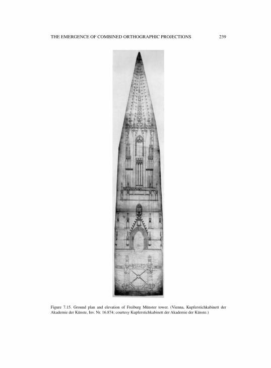
THE EMERGENCE OF COMBINED ORTHOGRAPHIC PROJECTIONS 239
Figure 7.15. Ground plan and elevation of Freiburg Münster tower. (Vienna, Kupferstichkabinett derAkademie der Künste, Inv. Nr. 16.874; courtesy Kupferstichkabinett der Akademie der Künste.)
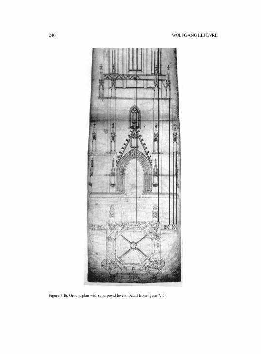
240 WOLFGANG LEFÈVRE
Figure 7.16. Ground plan with superposed levels. Detail from figure 7.15.
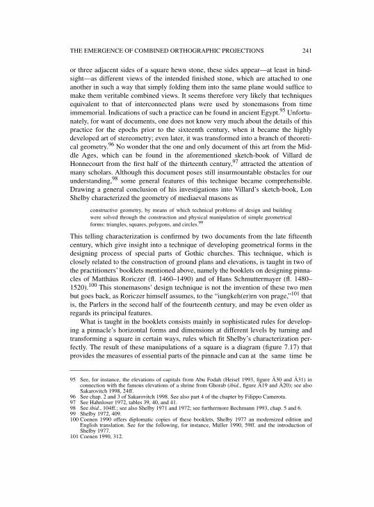
THE EMERGENCE OF COMBINED ORTHOGRAPHIC PROJECTIONS 241
or three adjacent sides of a square hewn stone, these sides appear—at least in hind-sight—as different views of the intended finished stone, which are attached to oneanother in such a way that simply folding them into the same plane would suffice tomake them veritable combined views. It seems therefore very likely that techniquesequivalent to that of interconnected plans were used by stonemasons from timeimmemorial. Indications of such a practice can be found in ancient Egypt.95 Unfortu-nately, for want of documents, one does not know very much about the details of thispractice for the epochs prior to the sixteenth century, when it became the highlydeveloped art of stereometry; even later, it was transformed into a branch of theoreti-cal geometry.96 No wonder that the one and only document of this art from the Mid-dle Ages, which can be found in the aforementioned sketch-book of Villard deHonnecourt from the first half of the thirteenth century,97 attracted the attention ofmany scholars. Although this document poses still insurmountable obstacles for ourunderstanding,98 some general features of this technique became comprehensible.Drawing a general conclusion of his investigations into Villard’s sketch-book, LonShelby characterized the geometry of mediaeval masons as
constructive geometry, by means of which technical problems of design and buildingwere solved through the construction and physical manipulation of simple geometricalforms: triangles, squares, polygons, and circles.99
This telling characterization is confirmed by two documents from the late fifteenthcentury, which give insight into a technique of developing geometrical forms in thedesigning process of special parts of Gothic churches. This technique, which isclosely related to the construction of ground plans and elevations, is taught in two ofthe practitioners’ booklets mentioned above, namely the booklets on designing pinna-cles of Matthäus Roriczer (fl. 1460–1490) and of Hans Schmuttermayer (fl. 1480–1520).100 This stonemasons’ design technique is not the invention of these two menbut goes back, as Roriczer himself assumes, to the “iungkeh(er)rn von prage,”101 thatis, the Parlers in the second half of the fourteenth century, and may be even older asregards its principal features.
What is taught in the booklets consists mainly in sophisticated rules for develop-ing a pinnacle’s horizontal forms and dimensions at different levels by turning andtransforming a square in certain ways, rules which fit Shelby’s characterization per-fectly. The result of these manipulations of a square is a diagram (figure 7.17) thatprovides the measures of essential parts of the pinnacle and can at the same time be
95 See, for instance, the elevations of capitals from Abu Fodah (Heisel 1993, figure Ä30 and Ä31) inconnection with the famous elevations of a shrine from Ghorab (ibid., figure Ä19 and Ä20); see alsoSakarovitch 1998, 24ff.
96 See chap. 2 and 3 of Sakarovitch 1998. See also part 4 of the chapter by Filippo Camerota.97 See Hahnloser 1972, tables 39, 40, and 41.98 See ibid., 104ff.; see also Shelby 1971 and 1972; see furthermore Bechmann 1993, chap. 5 and 6.99 Shelby 1972, 409.100 Coenen 1990 offers diplomatic copies of these booklets, Shelby 1977 an modernized edition and
English translation. See for the following, for instance, Müller 1990, 59ff. and the introduction ofShelby 1977.
101 Coenen 1990, 312.
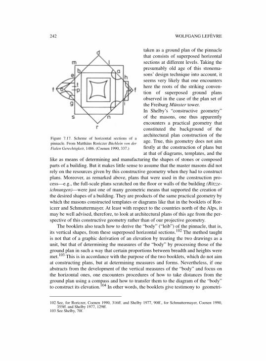
242 WOLFGANG LEFÈVRE
taken as a ground plan of the pinnaclethat consists of superposed horizontalsections at different levels. Taking thepresumably old age of this stonema-sons’ design technique into account, itseems very likely that one encountershere the roots of the striking conven-tion of superposed ground plansobserved in the case of the plan set ofthe Freiburg Münster tower. In Shelby’s “constructive geometry”of the masons, one thus apparentlyencounters a practical geometry thatconstituted the background of thearchitectural plan construction of theage. True, this geometry does not aimfirstly at the construction of plans butat that of diagrams, templates, and the
like as means of determining and manufacturing the shapes of stones or composedparts of a building. But it makes little sense to assume that the master masons did notrely on the resources given by this constructive geometry when they had to constructplans. Moreover, as remarked above, plans that were used in the construction pro-cess—e.g., the full-scale plans scratched on the floor or walls of the building (Ritzze-ichnungen)—were just one of many geometric means that supported the creation ofthe desired shapes of a building. They are products of the same practical geometry bywhich the masons constructed templates or diagrams like that in the booklets of Ror-iczer and Schmuttermayer. At least with respect to the countries north of the Alps, itmay be well advised, therefore, to look at architectural plans of this age from the per-spective of this constructive geometry rather than of our projective geometry.
The booklets also teach how to derive the “body” (“leib”) of the pinnacle, that is,its vertical shapes, from these superposed horizontal sections.102 The method taughtis not that of a graphic derivation of an elevation by treating the two drawings as aunit, but that of determining the measures of the “body” by processing those of theground plan in such a way that certain proportions between breadth and heights weremet.103 This is in accordance with the purpose of the two booklets, which do not aimat constructing plans, but at determining measures and forms. Nevertheless, if oneabstracts from the development of the vertical measures of the “body” and focus onthe horizontal ones, one encounters procedures of how to take distances from theground plan using a compass and how to transfer them to the diagram of the “body”to construct its elevation.104 In other words, the booklets give testimony to geometri-
102 See, for Roriczer, Coenen 1990, 316ff. and Shelby 1977, 90ff., for Schmuttermayer, Coenen 1990,355ff. and Shelby 1977, 129ff.
103 See Shelby, 70f.
Figure 7.17. Scheme of horizontal sections of apinnacle. From Matthäus Roriczer Büchlein von derFialen Gerechtigkeit, 1486. (Coenen 1990, 337.)

THE EMERGENCE OF COMBINED ORTHOGRAPHIC PROJECTIONS 243
Figure 7.18. Ground plan and elevation coordinated. From Matthäus Roriczer Büchlein von der FialenGerechtigkeit, 1486 (left), and Hans Schmuttermeyer Fialenbüchlein, c. 1485 (right). (Coenen 1990, 337and 365.)
104 Additionally, the advantage of superposed ground plans becomes visible if it is, as in the case ofpinnacles, about the determination of the vertical shapes of building parts that narrows towards the top.
244 WOLFGANG LEFÈVRE
cal methods of determining the vertical shapes of building parts based on the groundplan, which are of immediate bearing for the construction of elevations.
With respect to Dürer’s method of combined views, two points of the booklets’elevation construction are of special interest. The one is of linguistic nature. Roriczeruses the words “den grunt auszczihen” and “ausczug”105 to designate the action andthe result, respectively, of the construction of an elevation, and also indicates thatthese denominations are the established terms of the craft.106 These are, however,exactly the terms Dürer uses for the construction of elevations as quoted above: “sie[die Schnecke] von unden ubersich ziehen” or “der schneck auß dem grund auf gezo-gen.”107 The language that Dürer uses in the Underweysung is obviously closelyrelated to, if not dependent on, that connected with the practical geometry of masonsas documented in the contemporary masons’ booklets. This is one of the reasons whyDürer scholars regard it an established fact since Staigmüller’s essay from 1891 thatthe knowledge of the Gothic masons and goldsmiths form a important backgroundfor his practical geometry.108
The second interesting point concerns the arrangement of the figures in themasons’ booklets. As already said, the booklets teach a method of deriving the mea-sures of the “body” from those of the ground plan that is geometric, but does not con-sist in a graphic derivation of the elevation from the ground plan by arranging the twoplans in such a way that they can treated as a unit. Accordingly, the booklets’ dia-grams that represent ground plans and elevations are usually separated from eachother and drawn to different scales. But, in each of the booklets, there also is one ortwo drawings where a ground plan is coordinated with an elevation in the manner ofcombined views (figure 7.18). It is, of course, not possible to determine whether thisarrangement of ground plan and elevation can be taken as a trace of a more graphicmethod of deriving the one plan from the other and, thus, whether such a method wasin use in the realm of the stonemasons’ practical geometry, but is not dealt withexplicitly by Roriczer and Schmuttermayer. But these drawings show in any case thatit was obviously not an unfamiliar feature of this practical geometry to coordinateplans of the same scale and with perpendicular planes, a coordination, which can beregarded as the practical key for the combined views technique. It therefore has theappearance that this geometry constitutes the practitioners’ knowledge sought as aroot and background of Dürer’s technique of combined views.
105 Shelby (ibid., 90) translates with “extrapolate the base plan” and “extrapolation,” respectively. It isessential to be aware of the close relation between the German “ziehen,” from which the verb“ausziehen” and the noun “Auszug” are derivatives, and “zeichnen:” “eine Linie ziehen” means “todraw a line;” thus, “draw out of the ground” may be a more adequate translation since “to draw” meansboth “to pull” and “to trace.”
106 “... merck der wirt gehayssen ...” (... note, it is called ...)—Coenen 1990, 316 and Shelby 1977, 90.107 “[…] to draw it [sc. the snail] up from below over itself”—“the snail drawn up out of the ground.” See
text and caption to figure 15 of the first book of Dürer 1983.108 See Günther 1887, 358, Staigmüller 1891, 50ff., Steck 1948, 83f. (note 6), and Peiffer 1995, 51ff.
8
PROJECTIONS EMBODIED IN TECHNICAL DRAWINGS: DÜRER AND HIS FOLLOWERS
JEANNE PEIFFER
INTRODUCTION
The aim of this chapter is to focus on technical drawings as mediators between prac-tical and theoretical knowledge. Albrecht Dürer’s Underweysung der Messung(Nuremberg 1525) offers some interesting examples of drawings embodying work-shop techniques and aspects of theoretical knowledge. My reading of these drawingswill make apparent a hitherto unnoticed aspect of Dürer’s notion of Messung, namelyconstruction in a visual space. In the second section, I look at the changes that occurin the understanding of that notion in its use by the immediate followers of Dürer,mainly in Nuremberg. Special attention is paid to the use of plans and instruments inthe representation practices developed from Dürer’s methods. The last section offersan outlook into the early seventeenth century, where on the one hand one encountersinvestigations of a more mathematical character with men like Egnazio Danti,Guidobaldo del Monte, and especially Girard Desargues, and on the other, some oftheir methods are discussed, criticized, and rejected by practitioners like the Parisianstonecutters. The chapter closes with a short depiction of the debate between Abra-ham Bosse and the French Academy, a debate in which the notion of representingthings as they are perceived, and not as they are, is violently rejected.
1. CONSTRUCTIVE GEOMETRY IN A VISUAL SPACE: ALBRECHT DÜRER
When Dürer calls the geometry, the instructions of which he is assembling, Messung(from messen, to measure), he is referring to a geometry that owes a lot to the Euclid-ean Elements, but is far from demonstrative geometry. It is a constructive, concreteand material geometry that Dürer has in mind, one which has to do with real objectsand artifacts that the artist can place before him (“vornemen”). He only once uses theLatin “geometria,” which clearly refers to Euclid. Thus gemessen linien are curvesconstructed pointwise by ruler and compass. The term gemessen may also evokethree-dimensionality as in gemessen leng (II.30),1 or the materiality of a line, asopposed to the abstract lines of Euclidean geometry. In his Underweysung der Mes-sung, Dürer aims to offer his companions a range of geometrical forms, regularlyconstructed by ruler and compass, be the construction exact or approximate. I willconcentrate in what follows on another aspect of his Messung, an aspect which has todo with vision. Some of Dürer’s drawings take into account the fact that the objects
1 See Dürer 1983, II.30. I adopt this condensed form to refer to Dürer’s Underweysung der Messung:book II, figure 30 or the text preceding the figure.
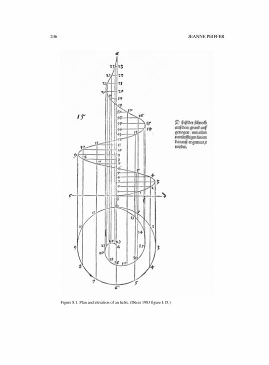
246 JEANNE PEIFFER
Figure 8.1. Plan and elevation of an helix. (Dürer 1983 figure I.15.)
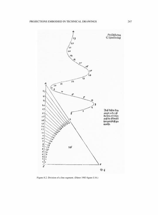
PROJECTIONS EMBODIED IN TECHNICAL DRAWINGS 247
Figure 8.2. Division of a line segment. (Dürer 1983 figure I.16.)
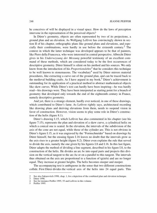
248 JEANNE PEIFFER
he conceives of will be displayed in a visual space. How do the laws of perceptionintervene in the representation of the perceived objects?
In Dürer’s geometry, objects are often represented by two of its projections, aground plan and an elevation. As Wolfgang Lefèvre has convincingly shown in sec-tion II of his chapter, orthographic plans like ground plans and elevations, and espe-cially their combinations, were hardly in use before the sixteenth century.2 Thecontext in which the latter technique was developed appears to be that of painters,like Piero della Francesca, who were interested in central perspective. Albrecht Dürergives in his Underweysung der Messung powerful testimony of an excellent com-mand of these methods, which are considered today to be the first occurrences ofdescriptive geometry. Dürer himself is silent on his method and his sources. We onlyknow from the introduction of his Proportionslehre3 that he considers this techniqueto be well known to stonemasons. The vocabulary4 used by Dürer mirrors materialprocedures, like extracting a curve out of the ground plan, and can be traced back tothe medieval building crafts. As I have argued in my book,5 Dürer’s achievement isoutstanding for its application of a practical method to abstract mathematical objectslike skew curves. While Dürer’s text can hardly have been inspiring—he was hardlyread—his drawings were. They have been interpreted as starting point for a branch ofgeometry that developed only towards the end of the eighteenth century in France,namely descriptive geometry.
And yet, there is a strange element, hardly ever noticed, in one of these drawings,which contributed to Dürer’s fame. As Lefèvre rightly says, architectural recordinglike drawing plans and deriving elevations from them, needs to suspend vision infavor of construction. However, vision seems to play some role in Dürer’s construc-tion of the helix (figure 8.1).
Dürer’s drawing I.15, which Lefèvre has also commented in his chapter (see hisfigure 7.15), represents the plan and elevation of a skew curve, a cylindrical helix onwhich a conical one is seated. In the elevation, the intervals of the subdivision of theaxis of the cone are not equal, while those of the cylinder are. This is not obvious inDürer’s figure I.15, as it was engraved by the “Formschneider” based on drawings byDürer himself, but the ensuing figure I.16 leaves no doubt that the intervals grow asthe axis rises to a greater height (figure 8.2). Dürer even explains the rule that servedto divide the axis, namely the one given by his figures I.8 and I.16. In this last figure,Dürer adapts the method of dividing a line segment, described in his figure I.8, to theconstruction of the helix. He divides an arc be into equal parts and projects this divi-sion on the vertical tangent to the arc ba or on a parallel to this tangent. The intervalsthus obtained on the axis are proportional to a function of tg(α/n) and are no longerequal. They increase at greater heights. The helix becomes steeper and steeper.
The accompanying text is ambiguous in the sense that two different constructionscollide. First Dürer divides the vertical axis of the helix into 24 equal parts. This
2 See also Sakarovitch 1998, chap. 1, for a depiction of the combined plan and elevation technique.3 Dürer 1996.4 See for instance Peiffer 1995, 55 and Lefèvre in this volume. 5 Peiffer 1995.
PROJECTIONS EMBODIED IN TECHNICAL DRAWINGS 249
Figure 8.3. Construction of a convex column. (Dürer 1983 figure III.7.)
250 JEANNE PEIFFER
instruction is immediately followed by a contradictory one: “However I want here tohave the intervals grow in the order explained above”6 (i.e. in his figure I.8). First,Dürer explains how to construct a skew curve by extracting its elevation from its plan.Second, if the curve is applied to the construction of a spiral staircase in the spire of atower, then the steps must be reduced in length in orderly progression the higher theyrise in the tower, i.e. the helix is conical, and the steps will grow progressively steepersuch that the axis is divided as in figure I.16 above. In the case of the construction ofa mathematical object, the intervals dividing the axis of its elevation are of equallength. In an architectural context, however, when building a circular staircase in thespire of a tower, the subdivisions have to be altered in order to conform with theexperience of steps becoming smaller and steeper when climbing up the tower. Düreroffers a construction that allows the desired effect to be obtained.
Book III of the Underweysung, which is dedicated entirely to architectural stud-ies, offers some other applications of the same dividing technique. In the openingsection, after some definitions of volumes, cones and pyramids, Dürer designs prima-rily columns, monuments and towers. Elements of decoration, like sun-dials and let-tering, close the book. Dürer explains how to generate a column or a pointed solid, apyramid or a cone, from a given ground plan. For instance, if the ground plan is a cir-cle, he produces a column by raising this circle up to the desired height7 and a coneby raising it towards a point.8 More generally, the “kunstreychen bauleut,” i.e. the art-ful builders in Strauss’ translation,9 know how to give the right volume, “in rechtermaß beleyben,” to a ground plan drawn with simple lines. They also know, from thegiven sections, how to decorate the columns and their different elements.10 Whenconstructing convex columns, Dürer applies the procedure described above (figures8.1 and 8.2) to decorate the shaft with spiraling lines (figure 8.3). He wastes not a sin-gle word on that application, which apparently is straightforward to him, except thathe insists on using the triangle abc in order to expand the intervals as they ascend,and to contract them as they descend.
The construction of a round twisted column, which follows, yields an even nicerexample (figure 8.4). Here Dürer starts with a description of the dimensions and pro-portions of the column he wants to construct, i.e. effectively, the description of a pro-file. He uses the diameter above its plinth as a module. The proportions he gives arethose of a ionic column in Vitruvius’ Architecture. Then he goes on with the groundplan “from which to extract the column while twisting it.”11 As the figure clearlyshows, this plan is composed of three circles with different diameters touching each
6 “Ich will aber hie die felt ubersich in einer ordnung erlengen / wie voren angetzeigt” (Dürer 1983,fol. Br).
7 “Ich nym zum ersten ein cirkelrund felt … und far eben mit ubersich so hoch ich will / so wirdt einrunde seulen darauß” (Dürer 1983, fol. Gr). From this quotation, the role played by plans and elevationsin the design of columns seems straightforward: the elevation fixes the different levels to which theforms contained in the ground plan will rise.
8 “Ich far aber auß allen forgemelten gründen ubersich / so hoch ich wil in ein spitz / so werden kegeldarauß” (Dürer 1983, fol. Gv).
9 Dürer 1977, 191.10 I am paraphrasing fol. Gij
v of Dürer’s Underweysung.11 “leg ein grund darauß du dise seulen winden must” (Dürer 1983, fol. Hv).
PROJECTIONS EMBODIED IN TECHNICAL DRAWINGS 251
other. Their peripheries are numbered with sixty subdivisions, beginning with pointa, the center of the large circle. In the smallest circle, point c has the number 6. Then,continuing with the middle-sized circle, along half his periphery, Dürer counts up to18 and starts with 19 on the large outer circle. Its whole circumference is subdividedinto points 19 to 42, then the division continues on the second half of the middle-sized circle until the point c is reached with the number 54. The second half of thesmall circle is divided into points 55 to 60, which coincides with the center a. Thesepoints in the ground plan show how the axis of the column must be twisted.
Next, the axis of the column in profile is divided into 60 irregular intervals. Theprocedure used by Dürer is by now familiar. He projects an equally divided arc on thevertical axis. Thus the intervals increase as they ascend. They all fit along a compassopened to a constant angle, or, in other words, in the triangles defined by the branchesof the compass and the intervals, the latter are the sides opposing the equal angles.According to the fourth postulate of Euclid’s Optics,12 these intervals would appearequal to an eye located at point f. Thus, let’s presume that Dürer’s diagram refers to avisual space in which the laws of Euclidean optics apply, i.e. that the visual rays pro-ceed in straight lines from the eye, and that the collection of such rays constitutes acone, of which the vertex is at the eye and the base at the surface of the objects seen.The apparent size of a visible object is determined by the visual angle that enclosesthe extremities of the object and the vertex of which is located in the observer’s eye.In such a visual space, the division process used by Dürer induces that the growingvertical intervals of that subdivision are perceived as equal by an eye f.
In other words, in his diagram, Dürer takes into account the fact that a magnitudeseen from underneath appears smaller than it is. To correct this perception, heincreases the intervals as they ascend in accordance with the order of Euclideanoptics. I will come back to the presence of an optical theory in these sophisticatedpractitioner’s drawings of architectural and mathematical objects. But for the momentlet me stress the highly innovative state of the construction as it is further describedby Dürer. We have seen that he conceives of the ground plan, with its three circlesdivided into the numbers 1 through 60, as a horizontal projection of a helix, which isto represent the twisted axis of a column. That’s why Dürer divides the elevation into60 horizontal planes, numbered from 1 at the bottom up to 60. Each horizontal sec-tion of the column is represented by a horizontal line segment whose length is equalto the diameter of the column, the axis of the column being an axis of symmetry. Inorder to twist the axis, Dürer applies the technique described in his figure I.15 (figure8.1), and applies to each horizontal line segment the displacement, taken from theground plan, which the corresponding point of the axis undergoes when twisted. Hethen imagines that each point of the twisted axis of the column can be the center of asphere whose diameter is precisely that of the column. If all their circumferences areconnected by a line, the contour of the column appears. The surface is thus defined (inour modern terms) as the envelope of a family of spheres with constant radius and
12 Let it be assumed that things seen under a larger angle appear larger, those under a smaller angle appearsmaller, and those under equal angles appear equal. Quoted from Lindberg 1976, 12.
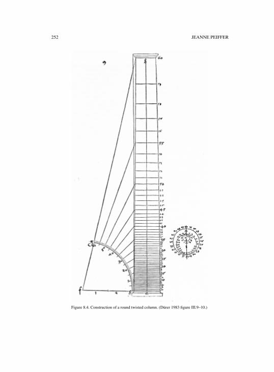
252 JEANNE PEIFFER
Figure 8.4. Construction of a round twisted column. (Dürer 1983 figure III.9–10.)
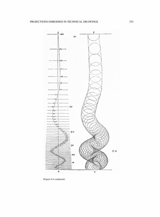
PROJECTIONS EMBODIED IN TECHNICAL DRAWINGS 253
(Figure 8.4 continued)
254 JEANNE PEIFFER
with their centers on a curve. Dürer’s drawing certainly inspired the founder ofdescriptive geometry, Gaspard Monge,13 when in his lessons held centuries later atthe newly founded Ecole de l’an III in revolutionary Paris, he taught on the so-called“surfaces de canaux.”
In my opinion, it is in this part of his Underweysung that Dürer’s excellent com-mand of methods later called descriptive is most obvious. His last sentence of thissection shows a good understanding of the nature of sections:
Whereas in a round column the horizontal lines represent only round surfaces and thelines are placed evenly one on top of the other, in the case of twisted columns these linesno longer lie one flat on top of the next; instead, they are displaced, or moved to and froabove or below the next horizontal line, or to one side of it. They are transformed intooblique or curved shapes. This is shown in its simplest form in the following diagrams.14
But let’s come back to the optical theory possibly underlying the drawings we havecommented upon. While Dürer clearly describes how to divide the vertical lines inthe drawings discussed above, he is silent on a possible connection to vision. Hewrites in a context where Euclidian optics15 is known to some extent, and we knowthat he himself is well-read on this subject. When in Venice, Dürer bought, in 1507, acopy of Euclid’s Elementa, edited and commented upon by Bartolomeo Zamberti16.This book contains a Latin translation of Theon’s recension of Euclid’s Optica. InDürer’s estate in London17 we find a manuscript in Dürer’s hand containing anextract, in German, of the axioms and propositions of that optics. Except for theorem16, which is incomplete, the translation is correct. Hans Rupprich has shown that the-orem 17 is not in Dürer’s, but in Willibald Pirckheimer’s hand. That was for him anopportunity to illustrate the kind of collaboration that the painter had established withhis humanist friend: while Pirckheimer translated Euclid’s text into German, Dürerwrote it down.
Moreover, Dürer bought in 1523 “ten books useful to painters” from the Senate ofNuremberg, among which a copy of a manuscript of Witelo’s “De perspectiva,”which had belonged to Regiomontanus’ library and was inherited by the astronomerBernhard Walther. The manuscript, today in Basel,18 doesn’t show any testimony of a
13 Gaspard Monge, Application de l’analyse à la génération des surfaces courbes (1807), fol. XIV. SeeBruno Belhoste and René Taton, Leçons de Monge in Dhombres 1992, 267–459, 301 for the “surfacede canaux.”
14 See Dürer 1977, 213. In Dürer’s original German version: “Aber so in der geraden seulen die zwerchliniall rund ebnen bedeuten und gerad auf einander stend / so beleyben doch die selbenn linien in derwindung der krumen seulenn nicht mer blat auf einander / sunder schieben / hencken / und keren sichhin und her / ubersich undersich und nach der seyten / unnd werden schlemet ablang rundlecht liniendarauß. Dise hab jch nach dem schlechtesten nachfolget aufgeryssen” (Dürer 1983, fol. Hij
r).15 On the spread of Euclidean optics in medieval and Renaissance Italy, see for instance Federici
Vescovini 1983, and Cecchini 1998a. 16 Euclidis megarensis philosophi platonici mathematicarum disciplinarum janitoris : habent […]
elementorum libros XIII […] Bartolomeo Zamberto Veneto interprete, Venice 1505. Dürer’s copy withhis monogram is kept today at the Herzog August Bibliothek Wolfenbüttel. It bears the followinginscription: “daz puch hab ich zw Venedich vm ein Dugatn kawft im 1507 jor. Albrecht Dürer” (Thisbook I bought it in Venice for one ducat in the year 1507).
17 London, British Library, Add. Ms. cod. 5228, fol. 202 and fol. 211–219; 5229, fol. 77. 18 See Steinmann 1979, who identified Dürer’s copy.
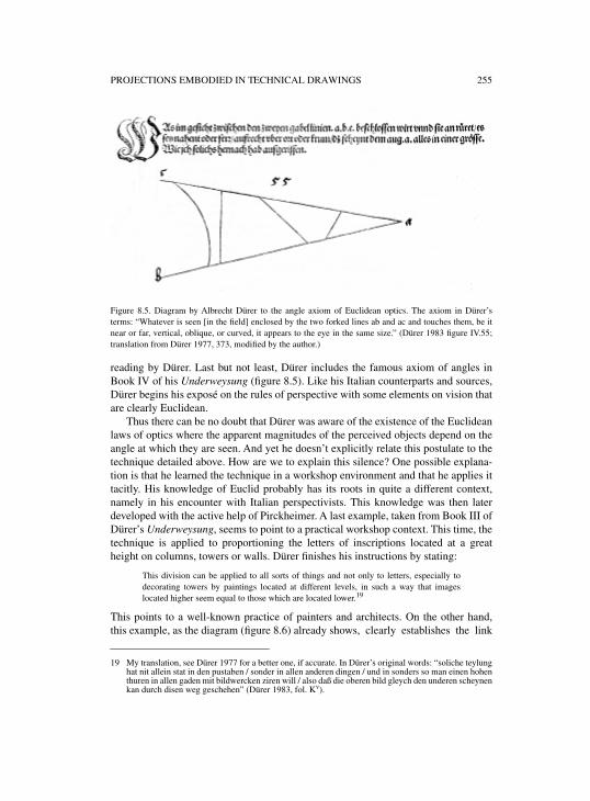
PROJECTIONS EMBODIED IN TECHNICAL DRAWINGS 255
Figure 8.5. Diagram by Albrecht Dürer to the angle axiom of Euclidean optics. The axiom in Dürer’sterms: “Whatever is seen [in the field] enclosed by the two forked lines ab and ac and touches them, be itnear or far, vertical, oblique, or curved, it appears to the eye in the same size.” (Dürer 1983 figure IV.55;translation from Dürer 1977, 373, modified by the author.)
reading by Dürer. Last but not least, Dürer includes the famous axiom of angles inBook IV of his Underweysung (figure 8.5). Like his Italian counterparts and sources,Dürer begins his exposé on the rules of perspective with some elements on vision thatare clearly Euclidean.
Thus there can be no doubt that Dürer was aware of the existence of the Euclideanlaws of optics where the apparent magnitudes of the perceived objects depend on theangle at which they are seen. And yet he doesn’t explicitly relate this postulate to thetechnique detailed above. How are we to explain this silence? One possible explana-tion is that he learned the technique in a workshop environment and that he applies ittacitly. His knowledge of Euclid probably has its roots in quite a different context,namely in his encounter with Italian perspectivists. This knowledge was then laterdeveloped with the active help of Pirckheimer. A last example, taken from Book III ofDürer’s Underweysung, seems to point to a practical workshop context. This time, thetechnique is applied to proportioning the letters of inscriptions located at a greatheight on columns, towers or walls. Dürer finishes his instructions by stating:
This division can be applied to all sorts of things and not only to letters, especially todecorating towers by paintings located at different levels, in such a way that imageslocated higher seem equal to those which are located lower.19
This points to a well-known practice of painters and architects. On the other hand,this example, as the diagram (figure 8.6) already shows, clearly establishes the link
19 My translation, see Dürer 1977 for a better one, if accurate. In Dürer’s original words: “soliche teylunghat nit allein stat in den pustaben / sonder in allen anderen dingen / und in sonders so man einen hohenthuren in allen gaden mit bildwercken ziren will / also daß die oberen bild gleych den underen scheynenkan durch disen weg geschehen” (Dürer 1983, fol. Kv).
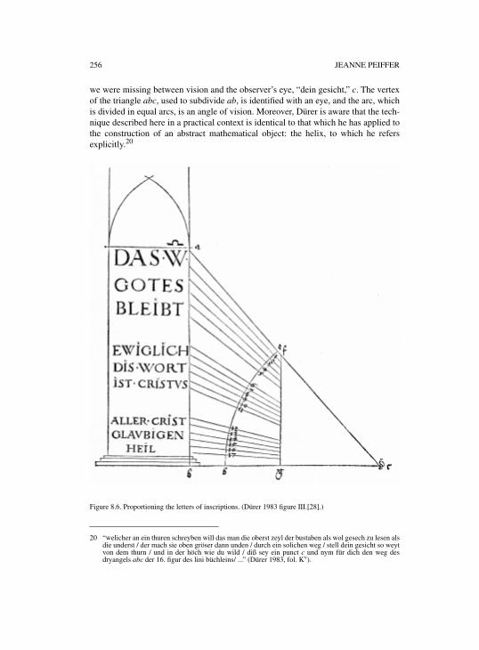
256 JEANNE PEIFFER
we were missing between vision and the observer’s eye, “dein gesicht,” c. The vertexof the triangle abc, used to subdivide ab, is identified with an eye, and the arc, whichis divided in equal arcs, is an angle of vision. Moreover, Dürer is aware that the tech-nique described here in a practical context is identical to that which he has applied tothe construction of an abstract mathematical object: the helix, to which he refersexplicitly.20
Figure 8.6. Proportioning the letters of inscriptions. (Dürer 1983 figure III.[28].)
20 “welicher an ein thuren schreyben will das man die oberst zeyl der bustaben als wol gesech zu lesen alsdie underst / der mach sie oben gröser dann unden / durch ein solichen weg / stell dein gesicht so weytvon dem thurn / und in der höch wie du wild / diß sey ein punct c und nym für dich den weg desdryangels abc der 16. figur des lini büchleins/ ...” (Dürer 1983, fol. Kv).
PROJECTIONS EMBODIED IN TECHNICAL DRAWINGS 257
Of course, the technique of correcting optical errors—equal magnitudes appearsmaller to the observer’s eye when situated higher—has a long history,21 going all theway back to Greek classical art. Plato22 already mentions artists who lend their sculp-tures proportions that appear harmonious without really being so. Recall the storyreported by Pliny, or by Iohannes Tzetzes (in the twelfth century), of a contestbetween Pheidias and Alcamenes for a Athena to be placed on top of a column. WhileAlcamenes’ statue was beautifully proportioned, Pheidias offered a statue with dis-torted members and he was barely saved from lapidation. The situation reversed com-pletely when the statues were put on top of the column. Vitruvius also gives advice tocorrect “falsa iudicia oculorum.” The procedure used to do this is the one based onEuclidean optics, known in the Western world since its Latin translation “De visu”and circulated in manuscript form in the second half of the twelfth century.23 It wasprobably part of the tradition of practical optics24 as established by Simi and Cam-erota.
All of the examples we have discussed in Dürer point to an architectural context,even the helix, which Dürer thinks of as at a staircase in the spire of a circular tower.Thus, the division technique, the aim of which is to make things located at differentheights appear equal, may well be a workshop technique distinct from, even if linkedwith, the Euclidean theory of vision.25 But on the other hand, his examples don’t fitthe conditions of effective practice. They seem to be a kind of school exercise asshown by the location of the eye at the bottom, and not at man’s eye level. The proce-dure may have been taught in practical abacus schools.
To sum up, an optical theory underlies Dürer’s architectural drawings, and evenhis diagram of a helix, when this mathematical object is used in an architectural con-text. The stonemason’s practice of representing things by means of a ground plan anda vertical section, an Auszug, enables Dürer to visualize the object in three dimen-sions and to display it in a visual space. In the construction process itself, he takesinto account the laws according to which vision proceeds. His vertical Auszug is anelevation only if we look at it in a space ordered by Euclid’s postulate.
Dürer’s diagrams are thus located at the intersection of practice and theory. Thisinterpretation is confirmed by at least one Italian follower of Dürer: Daniele Barbaro.In La pratica della perspettiva (1568), he comments on Dürers “artificio,” “instru-mento,”26 and on
the rule and form of the quadrant ..., which serves to fix the proportions of the letters orfigures which are located high up in some column or wall. With the help of it, paintersand architects know to divide the heights in proportional parts27
21 See Frangenberg 1993 and Cecchini 1998b. 22 Plato Sophistes, 235–236.23 See for instance Cecchini 1998a.24 See Simi 1996 and Camerota 1998.25 In a paper entitled “L’optique euclidienne dans les pratiques artisanales de la Renaissance,” to appear
in Oriens-Occidens. Sciences, mathématiques et philosophie de l’Antiquité à l’Âge classique, I try tofind traces of this procedure closely linked to the practical tradition of “measuring by eye.”
26 See Barbaro 1568, 23.
258 JEANNE PEIFFER
and establishes a double link with the painters’ and architects’ knowledge on onehand, and with Euclid’s Optics on the other, whose angle axiom he quotes.28
The technique described by Dürer, developed considerably in the baroque world,where it became important in creating artificial effects such as accelerating perspec-tives, but that’s beyond the scope of the present study.
2. FROM EUCLIDEAN OPTICS TO PERSPECTIVE: THE CASE OF SIXTEENTH-CENTURY KUNSTBÜCHER. WITH PARTICULAR
EMPHASIS ON HANS LENCKER’S PERSPECTIVA (1571)
In this section, the emphasis will be on the use Dürer’s immediate followers inNuremberg made of orthographic plans. As it is well known, Dürer’s instructionswere not immediately understood by the practical men to whom his book wasaddressed. In their eyes, these instructions needed some mediations, simplificationsand further explanations to be useful and applicable to the crafts. Thus during the six-teenth century a host of booklets, the so-called Kunstbücher, was published mainly,but not exclusively, in Nuremberg, the aim of which was explicitly pedagogical. Forinstance, Augustin Hirschvogel,29 painter on glass in a Nuremberg workshop, authorof a Geometria (1543) and later “Mathematicus” of the city of Vienna, intends tooffer beginners a better understanding of the basic principles and the practical appli-cations of the art of measuring, “die edle und nützliche kunst des messens (Perspec-tiva in Latein genant),” unlike previous books, which are often obscure and hide themost necessary and noble aspects.30 To a certain extent these books may thus grant usa glimpse of what was transmitted to apprentices in sixteenth-century Nuremberg,especially in the domain of constructive geometry, plan and elevation techniques, aswell as in perspective.
The first point I want to make is that the understanding of Dürer’s notion of “Mes-sung” seems to have undergone some change. It is now used as a German translationof the Latin “perspectiva.” Count Johann II of Simmern in his Underweysung derKunst des Messens (1531) had already transcribed the Latin Perspectiva in German as“kunst des Augenmeß” (art of measuring by eye).31 The notion of representation,namely in the form of perspective painting, is thus added to Dürer’s constructivegeometry. To be more precise, the visual appearance of things displayed in a three-
27 “Dalle dette cose si comprende la regula, & la forma del quadranto di Alberto Durero, col quale egliproportiona le lettere, overo le figure, che sono nell’altezza di qualche colonna o parete. Dalche sonoavertiti i Pittori, overo gli Architetti a partire le altezze in parti proportionate” (Barbaro 1568, 9).
28 “Le cose, che si vedeno sotto anguli eguali pareno eguali” (Barbaro 1568, 10, § G).29 On Hirschvogel, see Kühne 2002.30 See the dedicatory letter of Hirschvogel 1543, fol. a2r: “Nach dem bißher / durch unsere vorfordern /
ein langezeit dise edle und Nützliche kunst des messens (Perspectiva in Latein genant) in Deutschersprach verborgen gehalten / und den gemeinen man / zulernen schwerlich zu bekommen / Auch denmeren Thail in Griekischer und Lateinischer sprach verfast / Was derselben bücher in Truck seinkommen / etwas tunckel / und das notigist und fürnembst / gewönlich dahinten behalten worden / Dasdann manchen kunstbegirigen / der solchs gelesen / den buchstaben verstanden / aber zu keinenhandtbrauch gelangt hat / abschewlich / und verdrießlich ist gewesen.”
31 Johann II von Simmern, in the title of his 1546 Perspective, addressed his instructions to “all those whowant to use the art of measuring by eye (called Perspectiva in Latin).”
PROJECTIONS EMBODIED IN TECHNICAL DRAWINGS 259
dimensional space and depending on the visual angle are replaced by perspective rep-resentations of those same things, the foreshortening of which depends on their dis-tance from the eye. The means to obtain those images remain in part the same,namely orthographic plans, which can be conceived of as belonging to architecture,32
as Walter Ryff states in the perspective book of his Der fürnembsten / notwendigsten /der gantzen Architectur angehörigen Mathematischen und Mechanischen künst /eygentlicher bericht (1547), where he translates passages by Alberti, Serlio, and Vit-ruvius into German. Ryff (or Rivius), a physician who spent some years in Nurem-berg and published a German translation of Vitruvius’ architecture, is a quite prolificwriter on perspective. He is conscious that teaching perspective by the written word isa difficult task namely because “of the solids on the plane raised out of the groundplan.”33 And yet without this technique of drawing geometric plans (“Geometrischergrund”), nobody will be able to master the art of perspective, which Ryff identifieswith Vitruvius’ Scenographia.
By including perspective in their understanding of “Messung,” these men—likeDürer—see it as part of a practical geometry in which the observer’s eye plays a role.But instead of constructing three-dimensional objects, they represent them on a pic-ture plane, as Dürer already did in the very last section of his Underweysung der Mes-sung. But while Dürer clearly referred the picture plane to the intersection of thevisual pyramid, this Albertian model is completely absent from the Kunstbücher.These seem related rather to that older tradition of practical (applied) optics.Goingback to the Arabs, it was taught in the medieval abacus schools, and its methods wereused by astronomers, geographers, and architects in order to deduce from the appear-ances of distant or inaccessible magnitudes, their real measures. According to theArab philosopher al-Farabi (tenth century),34 who lists this practical optics in hisclassification of the mathematical disciplines, it also includes optical corrections ofthe sort studied in my first section. So, at least in Nuremberg, although the Albertianrules are available in Ryff’s writings, very rough perspective workshop methodsdevelop as part of the art of measuring by eye. Note that for Francesco di GiorgioMartini, the painter’s perspective also belonged to that tradition of “misurazione conla vista.”
“Messung,” as understood by the authors of the sixteenth-century NurembergKunstbücher, thus aims to construct perspectival representations of more or less com-plex solids, most of them polyhedral. Some applications to architectural settings arediscussed in most of these treatises. As far as the methods are concerned, they essen-tially consist in drawing plans and their perspectives in already foreshortened planes.Hirschvogel, for instance, teaches in his Geometria “how to obtain the ground plansof regular and irregular solids, to throw them into perspective, and to give an eleva-
32 Ryff 1547, in the lengthy summary of Book III, speaks of: “der Architectur angehörigen Kunst von derGeometrischen Messung.”
33 See Ryff 1547, fol. cciijr: “Obgleich wol die trefflich kunst der Perspectiva vast schwer und müsam /
schrifftlich zuhandlen und tractieren / fürnemlichen aber der Corper halben / auff der ebne aus demgrund auffgezogen.”
34 See Jolivet 1997, 260.
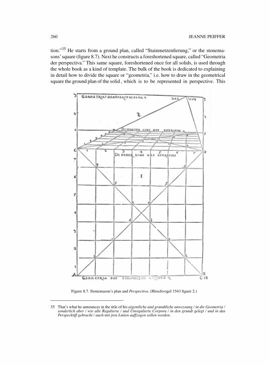
260 JEANNE PEIFFER
tion.”35 He starts from a ground plan, called “Stainmetzenfierung,” or the stonema-sons’ square (figure 8.7). Next he constructs a foreshortened square, called “Geometriader perspectiva.” This same square, foreshortened once for all solids, is used throughthe whole book as a kind of template. The bulk of the book is dedicated to explainingin detail how to divide the square or “geometria,” i.e. how to draw in the geometricalsquare the ground plan of the solid , which is to be represented in perspective. This
35 That’s what he announces in the title of his aigentliche und grundtliche anweysung / in die Geometria /sonderlich aber / wie alle Regulierte / und Unregulierte Corpora / in den grundt gelegt / und in dasPerspecktiff gebracht / auch mit jren Linien auffzogen sollen werden.
Figure 8.7. Stonemason’s plan and Perspectiva. (Hirschvogel 1543 figure 2.)
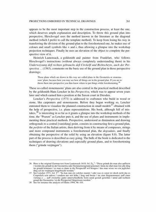
PROJECTIONS EMBODIED IN TECHNICAL DRAWINGS 261
appears to be the most important step in the construction process, at least the one,which deserves ample explanation and description. To throw this ground plan intoperspective, Hirschvogel uses the method known in the literature as the diagonalmethod (which I prefer to call the template method). To keep from losing his way intransferring the division of the ground-plan to the foreshortened one, he makes use ofcolours and small symbols like + and d, thus allowing a glimpse into the workshopprojection techniques. Finally he uses an elevation of the object to complete the per-spective view of it.
Heinrich Lautensack, a goldsmith and painter from Frankfurt, who followsHirschvogel’s instructions (without always completely understanding them) in hisUnderweysung deß rechten gebrauchs deß Circkelß und Richtscheyts, auch der Per-spectiva … (1563), comments on the basic use of the ground plan in those perspectivedrawings:
Those plans which are drawn in this way are called plans in the Geometria or stonema-sons’ plans, because here you may see how all things are in the ground plan. If you are tothrow them into perspective you thus know where to put things while foreshortening.36
These so-called stonemasons’ plans are also central in the practical method describedby the goldsmith Hans Lencker in his Perspectiva, which was to appear seven yearslater and which earned him a position at the Saxon court in Dresden.
Lencker’s Perspectiva (1571) is addressed to craftsmen who build in wood orstone, like carpenters and stonemasons. Before they began working so, Lenckerentreated them to visualize the planned construction in small models37 obtained withthe help of perspective, i.e. plane representations. His book, although full of mis-takes,38 is interesting in so far as it grants a glimpse into the workshop methods of thetime, the “Praxen” as Lencker puts it, and the use of plans and instruments in imple-menting these practical methods. Perspective, understood as diminution and drawingorthogonals to a central [vanishing] point, consists in constructing first a ground plan,the perfetto of the Italian artists, then deriving from it by means of compasses, stringsand more compound instruments a foreshortened plan, the degradato, and finallyobtaining the perspective of the solid by using an elevation (figure 8.8). The latterpart of the process is described as easy going. The bulk of the book is dedicated to thetechniques of drawing elevations and especially ground plans, and to foreshorteningthem (“gründe verjüngen”).
36 Here is the original German text from Lautensack 1618, fol. Divv: “Diese gründt die man also auffreist
/ werden die gründt in der Geometria oder Steinmetzengrund genennet / denn da sihet man wie alle dingim grundt kommen / so man es dann in die Perspectiff wil bringen / das man wisse wo ein jeglichesding sol im verjüngen hingebracht werden.”
37 See Lencker 1571, fol. Vv: “So kan nun ein solches muster / oder was es sonst ist (doch nicht das esCorperlich sein müsse / sondern nur mit höhe / leng und breite / im sinn fürgenommen) auff einervierung a … auff zweierley gantz unterschiedliche form unnd gestalt gerichtet / unnd auß rechtemgrund der Geometria / in die Perspectief fürgerissen werden.”
38 See for instance the analysis of Elkins 1994, 96–101.
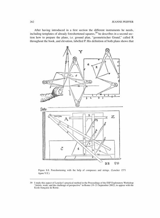
262 JEANNE PEIFFER
After having introduced in a first section the different instruments he needs,including templates of already foreshortened squares,
39
he describes in a second sec-tion how to prepare the plans, i.e. ground plan, “geometrischer Grund,” called Rthroughout the book, and elevation, labelled P. His definition of both plans shows that
39 I study this aspect of Lencker’s practical method in the Proceedings of the ESF Exploratory Workshop“Artists, work, and the challenge of perspective” in Rome (19–21 September 2002), to appear with theEcole française de Rome.
Figure 8.8. Foreshortening with the help of compasses and strings. (Lencker 1571figure Y/Z.)
PROJECTIONS EMBODIED IN TECHNICAL DRAWINGS 263
we are far from a familiar projection technique. Lencker is appealing to the imagina-tion and the experience of the apprentice. The ground plan located under the groundline, i.e. the intersection of the picture plane and the ground plane, is introduced asfollows:
all these plans you have to imagine them as the place or space straight from above whicheach thing (as a building, corpora or other, may it be polyhedral or circular, standinglying or oblique, largest at the bottom, in the middle or at the top, elevated at its two cor-ners, at one or in the middle, or however you may imagine) would cover perpendicular-iter on the horizontal plane, table or square, if it were a solid.40
He similarly defines an elevation as “the space or place which would be covered bysome solid or building, by the rising points of its height and width (not perpendicular-iter) but à latre (sic) on the sides like on a vertical wall.”41
Two of Lencker’s remarks deserve to be put forward in the context of this chapter. Tobring the notions of plan and elevation closer to his reader, Lencker uses an analogywith the work of carpenters,42 who first prepare floors and ceilings according to theirlength and width from their geometrical plans R. Even if they build columns, wallsand vertical elements when laid down, all their thoughts are oriented towards howthese elements will raise out of the ground plans (ligend gründ) according to plans P.Thus, it appears that, among craftsmen, carpenters are the ones who know best howto realize plans and to build in wood according to those plans. In Lencker’s eyespainters are less informed. But once they have learned to draw the plans, it will beeasy to obtain a perspective representation. The second remark points to architects,who already know how to draw plans. Lencker’s perspective method will be conve-nient and particularly handy for them.43 It is the method44 called the circumscribedrectangle method by Elkins, the diagonal method by Kirsti Andersen and which Iwant to call the template method.
Taking a square and an already foreshortened square as a picture plane, thismethod allows the image of an arbitrary point of the geometrical square to be found
40 See Lencker 1571, fol. VII: “Und alle dise gründe unterthalb der Erdlinie / mustu dir eigentlich also fürund einbilden / als den platz oder rhaum / welchen ein jedes ding (als Gebew / Corpora oder anders /es sey ecket oder rund / es stehe / lige / leine / es sey unten / mitten oder oben / am breitesten / es seymit beiden orten / mit einem / oder nur mitten erhoben / oder wie es sonst erdacht werden mag) geradvon oben herab auff einem Estrich / tisch / oder vierung a Perpendiculariter bedecken würde / wansCörperlich were / das ist sein rechter Geometrischer grund.”
41 See Lencker 1571, fol. VIIr/v: “Den grund aber oberhalb der linie m mustu verstehen gleich wie disen/ als den rhaum oder platz / welchen ein jedes Corpus oder Gebew mit den auffsteigenden punctenseiner höhe unnd breite (doch nicht Perpendiculariter) sondern à latre, nach der seiten / als an einerauffrechten wand / bedecken würde…”
42 See Lencker 1571, fol. VIIv: “Und haben dise beide gründe R und P gar ein ebens gleichnuß / mit demwerck der Zimmerleut / welche erstlich alle deck unnd böden nach der leng unnd breite auff jreGeometrische gründ richten / nach art des grundes R. Demnach ob sie wol alle auffrechte Gebew / alsSeulen / Wend / unnd Gibel / auch niderligend zu werck ziehen / so stehen doch gleichwol alle jregedancken dahin / wie sich hernach im auffrichten / solche Seulen / Wend / und Gibel / mit Düren undFenstern / auff die ligenden gründ schicken werden / nach art des grundes P.”
43 See Lencker 1571, fol. VIIIv: “Bistu ein Architectus des Maßwercks und der Gebew / sampt der selbengründe / verstendig / so wird dir sonderlich und vor allen diser weg und gebrauch der Perspectiefbequem / leicht / und sehr dienstlich dazu sein.”
44 On this method, see Elkins 1994, 96–101; Ivins 1973; Peiffer 1995, 111–112; Schuritz 1919, 43–44;and Staigmüller 1891, 46.
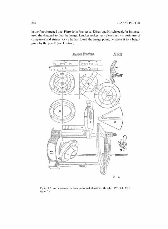
264 JEANNE PEIFFER
in the foreshortened one. Piero della Francesca, Dürer, and Hirschvogel, for instance,used the diagonal to find the image. Lencker makes very clever and virtuosic use ofcompasses and strings. Once he has found the image point, he raises it to a heightgiven by the plan P (an elevation).
Figure 8.9. An instrument to draw plans and elevations. (Lencker 1571 fol. XXII,figure 6.)
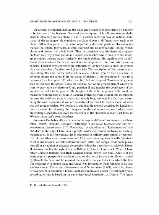
PROJECTIONS EMBODIED IN TECHNICAL DRAWINGS 265
As already mentioned, making the plans and elevations is considered by Lenckerto be the core of the business. Seven of the ten figures of his Perspectiva are dedi-cated to obtaining various planes P and R. Lencker seems to have an optimal com-mand of the technique. He combines the plans drawn in different ways such as toobtain different objects, or the same object in a different position. His examplesinclude the sphere, polyhedra, a spiral staircase and an architectural setting, whichcloses and crowns the whole book. Thus he considers (see his figure 6) a sphereenclosed by a ring whose section is a square, and teaches how to draw it in two differ-ent positions: the ring stands vertically, the ring is oblique. His juggling with the dif-ferent plans to obtain the desired result is quite impressive. For those who spare noexpense, Lencker even conceives an instrument (G on his figure) to draw the groundplan and elevation of a given solid (figure 8.9). The description of this instrument isquite straightforward. In the half circle A made in brass, you fix half a diameter Bpivoting around the screw F. In the socket (Hülslein) C moving along B, you fix adry-point (or a lead pencil) D, which can be lifted and dropped. To obtain the groundplan R, you drop this point D onto the solid G, half of the ground plan of which youwant to draw, turn the platform E into position H and transfer the coordinates of thepoint of the solid to the plan R. The heights of the different points of the solid aremeasured with the help of point D. Lencker prefers to work without this instrument,because the solid you want to draw must already be given, which is far from alwaysbeing the case, especially if you are an architect and want to show a model of whatyou are going to realize. We should also add that the method described by Lencker isquite accurate for drawing the complex polyhedral representations, which wereNuremberg’s specialty and even its trademark in the sixteenth century. Just think ofWentzel Jamnitzer’s beautiful plates!
Johannes Faulhaber, 40 years later and in a quite different professional and theo-retical context, includes Lencker’s instrument in his Newe Geometrische und Per-spectivische Inventiones (1610). Faulhaber,45 a schoolmaster, “Rechenmeister” and“Modist” in the city of Ulm, was a prolific writer and earned his living in teachingmathematics. In his Inventiones, he is interested in military applications of perspec-tive. He describes some instruments useful for easily drawing what he calls “planime-trisches Grundlegen” of fortifications, bastions, cities, and camps. To do so he placeshimself in a tradition of practical perspective, which he traces back to Albrecht Dürer.He follows this line through Gualterus Riff (sic), Heinrich Lautensack, Wentzel Jam-nitzer, Daniele Barbaro, and Hans Lencker among others. For him, Dürer is at thebeginning of a perspectival tradition based on the use of instruments. He was copiedby Daniele Barbaro, and he inspired the so-called Perspectivtisch in which the lutewas replaced by a simple plan, and which was included by Paul Pfinzing in his Einschöner kurtzer Extract der Geometriae unnd Perspectivae (1599), where he claimsto have seen it in Jamnitzer’s house. Faulhaber improves Lencker’s instrument which,according to him, is based on the same theoretical foundation as Dürer’s. The figure
45 On Faulhaber, see Schneider 1993.
266 JEANNE PEIFFER
is inverted and from the point of vision the sight falls on the object perpendicularly;this is not the case in Dürer’s lute woodcut, where the point of vision is fixed on thewall (figure 8.10).46
In my view there is another big difference between the two figures by Dürer andLencker that is interesting for my purpose. Dürer offers a material model for the
Figure 8.10. The painter with a lute. (Dürer 1983 figure IV.[64].)
46 See Faulhaber 1610, 35: “Weil er dardurch / so wol mit dem Perspectivtisch (doch auff die Maaß undWeiß / wie Albrecht Dürer / durch das Exempel / mit der Lauten angedeutet) als mit deß LenckersInstrument / so alle Puncten fleissig observiret werden / zum fertigen Handgriff kommen kan / dannbeyde Instrument / mit jhrem Gebrauch / auß einem Fundament zu demonstriren : Allein wird in deßLenckers die Figur umbgekehrt / der gestallt dz der Augpunct perpendiculariter herab fällt. Mir ist derPerspectiv Tisch mit der Seyten umb etwas angenemer / dieweil der Augpunct stetigs an einem Orthbleibt / und nit verändert wird.”
PROJECTIONS EMBODIED IN TECHNICAL DRAWINGS 267
visual pyramid, the vertex of which is at the point of vision, which is not a human eyein Dürer’s representation, but a nail in the wall. The sight is materialized by a string,cut by a transparent plane, the picture plane. The painter is doing nothing more thanmanipulating strings and passively recording measures. While Dürer’s famous wood-cut embodies a theory, the Albertian definition of perspective, Lencker’s instrumentand the way he represents it is first and foremost a technical device to draw plans.Thus, in the practical workshop tradition of such craftsmen as the Nuremberg gold-smiths, carpenters, and architects, the descriptive and perspective methods developedor described by Dürer are transformed into material devices, simple machines likestrings and templates, and into instruments designed to apply those techniques rathermechanically.
3. THE GEOMETRY OF PROJECTION INVESTIGATED BY MATHEMATICIANS IN THE SEVENTEENTH CENTURY
Orthographic projections, like those which the Nuremberg craftsmen learned to real-ize through some of the booklets we looked at in the preceding section, were usedsystematically in architectural treatises of the late sixteenth century, especially inItaly (Palladio, for instance). Plans and elevations, or horizontal and vertical ortho-graphic projections, were combined, as in Piero della Francesca’s De prospectivapingendi, in Dürer’s Underweysung der Messung, and also much later, for instance inSalomon de Caus’ La perspective avec la raison des ombres et miroirs,47 in order torepresent three-dimensional objects on a plane, either in perspective, i.e. as they areperceived, or by methods that were later subsumed under descriptive geometry. Thustwo distinct mathematical techniques are involved, which led, when taken over bymathematicians, to two distinct domains of geometry, namely projective geometryfounded in the seventeenth century by Desargues and Pascal, and descriptive geome-try introduced systematically by Monge towards the end of the eighteenth century. Inthis last section, we will have a rather quick look48 at the way mathematicians up tothe seventeenth century handle orthographic projections and their combinations.Then we will examine some of the known reactions of practical men, namely paintersand stonemasons, to the writings of professional mathematicians.
As Martin Kemp and J. V. Field have each emphasized, in the second half of thesixteenth century in Italy, painters’ perspective was taken over by humanists likeDaniele Barbaro and by professional mathematicians like Egnazio Danti, GiovanniBattista Benedetti, and Guidobaldo del Monte. In their hands, perspective underwenta significant change as different and more fundamental questions were asked, andcould slowly develop into a mathematical technique.
Daniele Barbaro, a Venetian patrician with a good humanist education, “a notablepatron”49 who had Palladio and Veronese work for him, wrote a Pratica della pers-
47 London 1612. On Salomon de Caus, see Bessot 1991.48 For this section we can rely on a rather important literature. See in particular Andersen 1991, Field
1997, Flocon and Taton 1963, Kemp 1990, Le Goff 1994. 49 See Kemp 1990, 76.
268 JEANNE PEIFFER
pettiva published in Venice (1568). J. V. Field sees it as a “spin-off from Barbaro’swork on Vitruvius.”50 Indeed, Barbaro prepared an Italian translation of Vitruvius’De architectura (Venice 1556) and published the original Latin text ten years later.His interest in the work of Vitruvius, which he amply annotated, is quite probably,according to Field, at least part of the reason for his interest in perspective. Pierodella Francesca and Albrecht Dürer are the main sources for the methods displayed inhis Pratica della perspettiva. He uses combined orthographic projections—plan andelevation—to give a perspective representation of objects, which are in most casesgeometrical solids. He also offers a perspective machine inspired by Dürer’s. Barbaroseems to take pleasure in the speculative opportunities offered by the study of mathe-matics. From the start, in his dedicatory letter, he claims that his mathematical studies“opened the route to high and subtle speculations”51 and regrets the absence of dem-onstrations in the work of contemporary painters who “let themselves be led by sim-ple practice.”52 In the first chapter of his treatise, introducing the principles andfoundations of perspective, he offers a twofold approach to perspective: a practicalone (as the title announces) and a more theoretical one referring to Euclid and Apol-lonius. His intention is to combine the experiments of art with the decrees of science.Being aware of the dependence of perspective on geometry and natural philosophy orphysics, he treats perspective as a “scienza subalterna,” subordinate to both sciences:from geometry, it receives the straight line, from physics the process of vision. Thevisual rays of perspective are simple lines without width if considered mathemati-cally, but belong to the tangible world if they are to be visible. Even though Barbaro’streatise offers hardly any geometrical demonstration, it assigns the painters’ tech-nique a place as a science subalternate to physics and geometry in the classificatorytree of science.53 The status of that technique is thus changed significantly.
Egnazio Danti,54 a professional mathematician who translated Euclid’s Opticsinto Italian (1573), considers perspective as an art depending on a science (optics)subordinated to geometry. To him, this is to say that it is impossible to proceed in per-spective according to the rigor of the Euclidean method. Nevertheless, Danti attemptsto provide geometrical proofs of the practical rules used by artists. Born in a Perugianfamily of artists, employed at the papal court in Rome, he is the author of an exten-sive commentary on the perspective rules of the architect Giacomo Barozzi daVignola. He edited for publishing the latter’s Le due regole (Rome 1583), makingsubstantial additions printed in a different typeface and providing additional illustra-tions. Vignola’s aim was to demonstrate that the two principal methods, i.e. the com-bined plan and elevation technique and the distance point technique, give the sameresult even if they look somewhat different in use. Showing the equivalence of twomethods is a completely new objective absent from earlier treatises. Practitioners cre-
50 See Field 1997, 133.51 Barbaro 1568 states: “ci è stata aperta la strada ad altissime e sottilissime speculationi” in the dedication
to “Al molto magnifico et eccellente M. Matheo Macigni,” which opens the book. 52 See Barbaro 1568, Proemio: “I Pittori dei nostri tempi ... si lasciano condurre da una semplice pratica.”53 On perspective as a mixed science, see Peiffer 2002a. 54 On Danti, see Dubourg–Glatigny 1999, Field 1997, 145–150 and Kemp 1990, 78–83.
PROJECTIONS EMBODIED IN TECHNICAL DRAWINGS 269
ated new methods and applied them to the representation of single forms, rather thanasking questions about the compatibility of existing methods.55 Danti further devel-ops this approach to perspective by focusing on geometrical proof and by offeringdifferent kinds of proofs for one proposition. Euclidean style proofs, which are some-times beyond the understanding of most practitioners, are often followed by aninstrument that makes the result tangible.
Mathematicians like Federico Commandino, Giovanni Battista Benedetti, andGuidobaldo del Monte moved further in this direction, as Kemp has shown convinc-ingly. With their treatises, as he puts it, “we see the birth of projective geometry as adiscipline in its own right, related to but increasingly separate from the painters’ sci-ence in its means and ends.”56 The university-trained Commandino, well remem-bered for his editions and translations of ancient Greek mathematics, recognized thatthe projection methods used in Ptolemy’s Planisphere, of which he gave an edition in1558, are related to perspective,57 of which he provides a mathematical treatment inLatin. As most commentators have underlined, Commandino gives here a piece ofmathematics addressed to mathematicians. Giovanni Battista Benedetti too made“first-class original contributions to the high tradition of mathematics arising out ofthe problems conceived within the practical one.”58 Best remembered for its mathe-matical style and approach, however, are the Perspectivae libri sex (Pesaro 1600)59
written by Guidobaldo del Monte, a nobleman trained by Commandino. His sixbooks on perspective were to become “the main source of reference for anyone seri-ously interested in the underlying geometry of perspectival projection.”60 Right fromthe start, Guidobaldo states his conviction that perspective is a mathematical science:“I would like to make it quite clear that the proper and particular object of the per-spectival science doesn’t differ from the object of geometry on which it depends.”61
The mathematical approach to perspective, which was definitively his, appears evenin the structure of the work. In his first book, he proves in a purely Euclidean style acorpus of propositions, which are to be applied to problem-solving in the followingbooks.
Yet in the history of mathematics it is Girard Desargues who receives much atten-tion as the founder of a new mathematical discipline, now called projective geometry,the methods of which easily can be connected from a mathematical point of view tothose of perspective. His most important work, a short treatise, which contains con-cepts and methods later subsumed under the term of projective geometry, appeared in
55 See Elkins 1994, 89.56 See Kemp 1990, 85.57 For a clear exposé of Commandino’s summary of perspective, see Field 1997, 150–161.58 This is the conviction of J. V. Field 1997, 171. See also Field 1985, Kemp 1990, 86–89.59 Guidobaldo del Monte has been studied in recent years especially by Rocco Sinisgalli 1984, who
translated his Six books on perspective into Italian, and Christian Guipaud, who presented an as yetunpublished French translation. Guipaud 1991 focuses on the important result proved by Guidobaldo,namely that any set of parallels in the scene to be portrayed will appear in perspective as a set of linesconverging to a point.
60 See Kemp 1990, 91.61 “Hoc namque in primis praecognitum esse cupio, proprium, ac peculiare obiectum scientiae
perspectivae nequaquam a subiecto geometriae, cui subalternatur, diversum esse.” (Del Monte 1600,I 3; Sinisgalli 1984, 240).
270 JEANNE PEIFFER
1639 in 50 copies and was entitled: Brouillon project d’une atteinte aux evenemensdes rencontres du cone avec un plan.62 In this treatise you can find a projective the-ory of the conic sections considered as perspective images of a circle. Some proper-ties of the circle can be transferred to the other conics—properties concerningintersection or contact for instance, but not measure—if you introduce new elementslike points at infinity. That is exactly what Desargues did. The perspective images ofparallel lines, as you know, intersect at a point of convergence, the vanishing point ofthe picture plane. If the parallel lines are considered as a pencil of intersecting lines(having their intersection point at infinity), then they are projected into a bundle ofintersecting lines.
As early as 1636 Desargues had already published a leaflet of scarcely twelvepages on perspective: Exemple de l’une des manieres universelles du S.G.D.L.touchant la pratique de la perspective sans emploier aucun tiers point, de distance nyd’autre nature, qui soit hors du champ de l’ouvrage.63 It shows a worked example,without proof, of Desargues’ perspective method. The core of the method is the intro-duction of scales, which give the progressive diminution in the width and height oflengths seen at greater distances from the picture plane, the position of the eyeremaining unchanged. Desargues speaks of “échelle des éloignements,” which is aperspectival scale for reducing orthogonal lengths in the picture and “échelle desmesures,” a scale of measures, which is geometrical and allows the measures of thedepicted transversals to be read on the ground line according to how far away they arelocated. The treatise is explicitly addressed to practitioners, even though a twentieth-century scholar has called it “a parody of a practical treatise.”64 It is of course inter-esting to know the family, social and training background of such an author. Archivalresearch done on the occasion of Desargues’ 400th birthday shows that Desarguesstemmed from a very wealthy family in Lyon and was perhaps better acquainted withthe works of the learned mathematical tradition than his published work reflects. Healso knew a great many of the practical traditions, but there is not much evidence thathe was a working engineer or architect. The only architectural realizations that can beattributed to him date from the period after 1644 and were motivated by the necessityto prove the superiority of his methods, which had come under attack.
In the light of current historical reconstructions, taking for granted that the projec-tive concepts introduced by Desargues, such as the point at infinity and involution,were rooted in his perspectival work, it is of course challenging to inquire about theconnections between Desargues’ work on perspective (1636) and his treatise on pro-jective geometry (1639). This was investigated by Kirsti Andersen and JanHogendijk:65
62 Rough draft for an essay on the results of taking plane sections of a cone in the translation of Field andGray 1987.
63 Example of one of S.G.D.L.’s general methods concerning drawing in perspective without using anythird point, a distance point or any other kind, which lies outside the picture field.
64 See Field 1997, 195.65 In a special issue of Centaurus devoted to Desargues, namely Centaurus 34(1991). For the following
quotation, see Andersen 1991, 45.
PROJECTIONS EMBODIED IN TECHNICAL DRAWINGS 271
The mere fact that perspective and projective geometry are related has been taken as anevidence that the insights Desargues gained while working on perspective were essentialfor his new approach to geometry.
Jan Hogendijk has shown that there is a strong historical relationship between theBrouillon project and the Conics of Apollonius. Thanks to his introduction of pointsand lines at infinity, Desargues was able to derive most of the Apollonian theory ofdiameters and ordinates in a much easier way than Apollonius.66 According toHogendijk, Desargues took not only most of his initial motivation from the Conicsbut also more raw material than has hitherto been realized. Kirsti Andersen studiesmore specifically the connection in Desargues’ writings between points at infinityand the vanishing points of perspective and obtains a more nuanced picture than theusual one. She discards vanishing points as a source of inspiration for Desargues’introduction of points at infinity.
Stereotomy and the Development of Descriptive Geometry
According to Joël Sakarovitch, who wrote an extensive history Epures d’architecturewith the significant subtitle “From stonecutting to descriptive geometry. 16th to 18thcenturies,” stereotomy is to descriptive geometry as perspective is to projectivegeometry,67 but he doesn’t tell what precisely in his view perspective is to projectivegeometry. The writings referred to in the previous subsection show that from a histor-ical perspective connections between the two are not straightforward but rather prob-lematic. From the abstract mathematical point of view, it is true that the geometricalconfiguration underlying perspective, a visual cone cut by a plane, has an obviouslink to conic sections interpreted as perspective images of a circle at the basis of thecone. It is also true that a vanishing point is a point at infinity, which one can add to aline. But from a historical perspective, things may be more complex, and it is notobvious that Desargues took his inspiration from the existence of vanishing points.Today, historical interpretations of the relations between painters’ perspective andprojective geometry are wide-ranging and divergent. Thus, at one end, the historianof art James Elkins claims that the connection is “virtually nonexistent.” To him,“mathematics and perspective have developed in parallel, mutually isolated streamssince the mid-sixteenth century.”68 At the other end, one can find the Husserlian the-sis of Hubert Damisch,69 interpreting perspective as an experimental ground forgeometry before it took a new start in the seventeenth century and again adopted its
66 Hogendijk 1991, 267 In Sakarovitch 1994, 347.68 See Elkins 1994, 3.69 “Tout se passe en effet comme si, avant de prendre au xviie siècle un nouveau départ, la géométrie avait
dû se donner, se constituer, comme elle l’aura fait à ses débuts, dans la Grèce antique, ce que lephilosophe Edmund Husserl a décrit, dans son opuscule sur L’Origine de la géométrie, comme un solpréalable d’expérience: quitte pour ce faire à s’écarter pour un long temps des voies qui étaient lessiennes et à parler un autre langage que strictement conceptuel, mais qui n’était pas non plus purementtechnique: celui des peintres et autres «perspecteurs», décorateurs, architectes ou tailleurs de pierre.”This quotation is taken from Damisch’s preface to Le Goff 1998, 5, but Damisch develops this thesis inDamisch 1987, which has been translated into English.
272 JEANNE PEIFFER
usual conceptual language. In between, one can find number of interpretations, mostof them tying perspective to certain mathematical developments, some (as Kemp,Field and Gray, Andersen, Hogendijk) painting a more nuanced picture of these ties.
What Joël Sakarovitch shows in his Epures d’architecture is that methods belong-ing to what we call descriptive geometry were developed out of problems that stone-cutters had to solve. The treatises of stereotomy, from Philibert de l’Orme’s Lepremier tome de l’architecture (1567) to Amédée-François Frézier’s La théorie et lapratique de la coupe des pierres (1737–39), are seen as direct sources for GaspardMonge’s descriptive geometry. Monge himself was active for two years in the work-shop for drawing and stonecutting at the Ecole du génie at Mézières, and knew quitewell the problems and methods of that craft. His aim in Géométrie descriptive (1795)was to describe the mathematical principles underlying the complex graphical tech-niques, i.e. the method of projections, to build a unified theory that could easily betaught, and to apply it to such crafts as stonecutting and carpentry.
In the sixteenth century, various methods were traditionally applied to stonecut-ting, among which one, which used horizontal and vertical projections of the arch-stone to be cut out on the faces of the rough block of stone. Thus, geometrization inthe form of orthographic projections—not necessarily laid down in drawings, butinscribed directly on the stone—was a necessary step in preparing stones before uti-lizing them in the planned building. It was at the origin of a large variety of graphicaltechniques, which were transmitted orally before they were collected and spreadthrough the first treatises. The famous French architect Philibert de l’Orme included atreatise on stereotomy as Books III and IV of his Le premier tome de l’architecture. Itis a kind of a catalogue of practical stonecutters’ methods put together without estab-lishing links between them, without any effort to single out common principles. Froma geometrical point of view, most problems to be solved by stonecutters concernintersections of two different surfaces. The stone-dresser (“appareilleur”)—the onewho prepared the drawings allowing the stonecutter to obtain neatly the various sur-faces bordering archstones—had to handle with sufficient precision complex surfacessuch as cones, cylinders, ellipsoids, and spheres, which require a good command ofmethods for representing space. De l’Orme makes extensive use of the plan and ele-vation technique in the stereotomy books, while he refrains elsewhere in the treatisefrom using combined orthographic views. In describing the methods of stonecut-ters—which wasn’t an easy task—, in putting into a written form procedures thatwere usually transmitted orally, in struggling to make them understood, in spreadingthem outside the realm of the craft, de l’Orme made a significant first move to singleout the underlying geometrical theory.
While de l’Orme had described various isolated practical cases more or lessfamiliar to his fellow architects, Girard Desargues, in his rough draft on stonecuttingin architecture published in 1640, pretends to give a general method, as the title of hisbook claims: Brouillon project d’une manière universelle du S.G.D.L. touchant lapratique du trait à preuves pour la coupe des pierres en l’architecture. Like in hisrough draft on perspective, he works out a single example. This example was not
PROJECTIONS EMBODIED IN TECHNICAL DRAWINGS 273
usual in the architectural practice of the time. Abstractly speaking, it involves a planecutting a cylinder, i.e. a cylindrical vault penetrates a non-vertical wall and anglesdownward (a situation, which implies that the axis of the cylinder is not horizontal).The geometrical construction of Desargues is elegant, but the text is dense andobscure (as usual with Desargues). It is impossible to enter into technical detailhere,70 but it is interesting to report on the reactions Desargues’ writing provokedamong practitioners.
Practitioners’ Responses to a Mathematician’s Work
The practitioners violently rejected Desargues’ geometrical approach to stereotomy.This led to a conflict between Desargues and Jacques Curabelle,71 known as the best“appareilleur” (dresser) of his time. A series of pamphlets, leaflets and posters wereprinted in 1644 by the two protagonists, the aim of which was to show the falsenessor the superiority of the stonecutters’ traditional methods or of Desargues’ proposal.To settle the question, Curabelle offered to organize a competition between twostonecutters, one following Curabelle’s preparatory drawings, the other applyingDesargues’ procedures. The outcome of the competition was to decide, in his mind,which of the two methods was the more exact and efficient. For him, only a concretepiece of work could test the precision of the two competing models. Desargues didn’tagree with this vision at all. What was important to him was the accuracy of the geo-metrical arguments. He asked that the two methods be submitted to a board of mathe-maticians able to evaluate and judge the theoretical foundations of bothconstructions. The working drawing was in his opinion sufficient to prove the exacti-tude of the construction; for Desargues there was no need to turn to a concrete real-ization in stone. On the contrary, the power of geometry is strong enough tolegitimate the construction. As Desargues formulates it with some brutality: “geome-ters … do not go to the school of stonemasons, on the contrary, masons … go to theschool and lessons of geometers, and thus the geometers are masters and the masonsapprentices.”72 This intense polemic between Desargues and Curabelle is the expres-sion of power struggles between mathematicians and practitioners for the controlover the crafts.
While Curabelle had the whole profession behind him, Desargues came more andmore under the attack of mathematicians and perspectivists such as Jean Dubreuil orJean François Niceron. But not everybody turned against Desargues. In particular, thecompetent engraver Abraham Bosse spent much energy in explaining, defending andtransmitting Desargues’ ideas.73 He is said to have followed courses by Desargues ongeometry applied to drawing. A convinced defender of Desargues’ methods, he wrotea treatise on stonecutting as well as a famous work on Desargues’ perspective.
70 See Sakarovitch 1994 and Sakarovitch 1998, 149–179.71 See Le Moël 1994 for biographical detail. See Desargues 1864, II 219–426 on the polemic.72 Quoted by Sakarovitch 1998, 181, who gives a beautiful analysis of the polemic.73 On Bosse and his relations to Desargues, see Heinich 1983, Kemp 1990, 120–123, Bottineau–Fuchs
1994, and Andersen 1991, 65.
274 JEANNE PEIFFER
Although not a full member of the Académie royale de peinture et de sculpture,founded in 1648 and located in Paris, whose president was the painter Charles LeBrun, Bosse was allowed to teach perspective at the Academy. He gave his first lessonon 9 May 1648, but became increasingly involved in a harsh dispute on the role ofperspective in painting, which lead finally to his exclusion on 11 May 1661. Such anexclusion seems to be unique in the history of the institution and one might wonderwhat the motives behind this severe treatment were. They are probably to be found inBosse’s notion of representation and in his allegiance to Desargues’ methods.74
Bosse aims to represent things as they are (according to the geometrical laws of pro-jection) and not as they are perceived subjectively: “You ought be careful not to drawthe relief or the natural as seen by the eye, but you should be able to reconstruct theproper ground plan of a painting putting various objects together.”75 This is exactlywhat Desargues’ methods tend to provide. However, the notion of representation,founded on strict geometrical laws, is violently rejected by the academicians who atthat time were seeking to discard such rigid laws.
For Abraham Bosse, the two practices of representing a solid by its ground plan orby a perspective view are identical.76 Bosse only repeats what Desargues had alreadyformulated in his 1640 rough draft on stonecutting: there is no
difference between the way to draw, reduce or represent a thing in perspective and theway to draw, reduce or represent it by a ground plan, ground and perspective plans arethus two species of a same genre, and they can be described and proved together, withthe same words.77
By identifying orthographic projections and perspective, Desargues shows that hehad understood clearly the link between cylindrical and central or conical projec-tions. This is also obvious in his rough draft on conic sections, where he introducescone and cylinder by a single definition of a roll (“rouleau”). A line is said to move sothat one of its points is fixed at finite or infinite distance, and that another turnsaround a circle. When the fixed point does not lie in the plane of the circle, the figureobtained is called a roll. Thus in writings partially addressed to practical men,Desargues rose to a level of abstractness that allowed him to treat horizontal and ver-tical orthographic projections (with the center of projection at infinity) in the sameway as perspective, i.e. central projection. Bosse made himself the champion ofDesargues’ abstract ideas. One may doubt that such ideas were useful to the artists atthe Academy. But this does not explain the vehemence of the debates and the viru-lence of the attacks against Bosse.78 Painters and artists, whose activities had gained
74 This is at least the thesis of Nathalie Heinich’s analysis of the bitter polemic at the Royal Academy ofPainting and Sculpture. See Heinich 1993, 147–152.
75 Quoted by Heinich 1993, 148: “Il faut bien se garder de dessiner le relief ou naturel comme l’œil le voit,mais bien de […] pouvoir remettre en son véritable géométral un tableau composé de divers objetsperspectifs.”
76 “ces deux pratiques de faire le trait de la représentation d’un corps en géométral, et en perspective, […]ne sont qu’une même chose” (quoted by Heinich 1993, 148).
77 “[il n’y a] différence aucune entre la manière de figurer, réduire, ou représenter une quelconque choseen perspective & la manière de figurer, réduire, ou représenter en géométral, aussi le géométral & leperspectif ne sont-ils que deux espèces d’un mesme genre, & qui peuvent estre énoncées ou démontréesensemble, en mesmes paroles.” (Quoted by Saint-Aubin 1994, 364).
PROJECTIONS EMBODIED IN TECHNICAL DRAWINGS 275
recognition as liberal arts and who were organized in an academic structure withroyal patronage, were struggling for their autonomy by eliminating the control ofgeometry.
CONCLUSION
In this chapter, we have analyzed some of the complex drawings in Albrecht Dürer’sUnderweysung der Messung (1525), which historical scholarship since the beginningof the twentieth century places in the same line as Gaspard Monge’s constructions. Inthese drawings, Dürer takes into account the laws of vision according to which thesemathematical and namely architectural objects must be seen. These laws are those ofEuclidean optics, a theory of appearances, and not the rules of perspective, althoughDürer did include a short presentation of perspective constructions in his book. Hisimmediate followers in the Nuremberg workshops drop the reference to Euclideanappearances. They invent various material devices and instruments in order to makeDürer’s perspective methods more efficient. In the books describing these devices,they call the whole domain Messung, a term which translates in their eyes to the Latinperspectiva. Thus, Messung includes methods, like central projections, which do notpreserve measure. Even if the Nuremberg craftsmen are not conscious of this fact,their main preoccupation, quite explicit in the treatises of Hirschvogel and Lencker, isthe problem of obtaining the horizontal orthographic projection, the Geometria orground plan, of the objects they want to portray. Having constructed the Geometria,or stonemasons’ square as they call it, they of course know the real measures of theobject. While the fabrique or the representation of the concrete object is at the centerof their concern, once professional mathematicians, like Danti, Commandino or delMonte move in, the projective ideas underlying this kind of construction increasinglyare studied for their own sake. In the seventeenth century Desargues clearly under-stands that measure is not preserved in projective transformations like those of per-spective. Other properties are, if the Euclidean space is completed by some idealelements. In his hands, a new geometrical discipline takes form, which is no longerconcerned with measure and can no longer be called Messung. That’s what Desarguesis suggesting when he writes: “The words perspective, appearance, representationand portrait are the names of one and the same thing.”79 The thing, which remainsunnamed by Desargues, is projective geometry.
78 See Desargues 1864, II 49–113, for some aspects of the polemic.79 See Desargues 1636, 1: “Les mots perspective, apparence, représentation, & pourtrait, y sont chacun le
nom d’une méme chose.”

PART VPRACTICE MEETS THEORY

INTRODUCTION TO PART V
In the period when the decisive steps toward classical mechanics were made (1500–1700), technical drawings played an important role in mediating between practicaland theoretical knowledge. This much-neglected function of early modern engineer-ing drawings is the topic of the last section of this volume.
Reflections and inquiries of a more theoretical nature were not at all beyond thehorizon of early modern engineering. Design processes are themselves reflection pro-cesses of a specific kind and cannot be cordoned off clearly from reflections on issuesconnected with the working of machines that properly could be called theoretical. Asalready discussed at several places in this volume, particularly in the chapters byMarcus Popplow, David McGee, and Pamela Long, technical drawings played animportant role in design processes. Naturally, the possibilities and restrictions thatsuch drawings provide for and impose on these designing reflections mark the powerand limits of drawings as means for general reflections about machines as well astheir working principles. With respect to the use of drawings for such more theoreti-cal purposes, the advantages and shortcomings of specific pictorial languages are ofparticular significance. It is not by chance that, as in the case of Leonardo’s note-books, drawings that doubtless served such general reflections often switched from apictorial style of representation to the diagrammatic one that was common in treatiseson mechanics. In this way, such reflections could make use of geometrical demon-strations and proofs that served as chief means of reasoning in early modern mechan-ics. However, these diagrams, whatever their advantages over more pictorialrepresentations, shared some of the principal limits characteristic of engineers’ mod-els on paper. Their representational potency was overtaxed if one tried to represent onone and the same diagram both the spatial relations of a device and physical quanti-ties such as its mass or forces acting upon it.
These limits of engineering drawings as means of theoretical reflections onmachines, however, must not obscure another significant role these drawings playedas mediators between practical and theoretical mechanics. As is now almost generallyacknowledged, early modern mechanics developed along with the technologicalinnovations of this period and hardly can be understood without this background.Almost all of the pioneers of preclassic mechanics were either engineers themselves,Tartaglia being probably the most prominent instance of such a theorizing engineer,or were occupied occasionally with engineering issues and tasks, as was the case withGalileo. The new technology provided a wealth of new subtle objects whose investi-gation advanced the understanding of the patterns and laws of the natural potencies ofwhich these devices made use. Yet to become truly familiar with the advanced tech-nology of the age, even in highly developed regions like the Padua-Venice area, per-sonal experiences with real machinery of some sort must be complemented byknowledge gained through representations of machines, either three-dimensionalmodels or technical drawings, and knowledge acquired elsewhere through the studyof tracts. It even might be possible that, for investigations of machines in a theoretical
280 INTRODUCTION TO PART V
perspective, drawings and other models were of even greater significance than realmachines.
The main topic of Michael Mahoney’s chapter is an exceptionally instructiveinstance of the power and limits of technical drawings for mediating between theoret-ical and practical mechanics. His example concerns diagrams by Christian Huygensthat were at the interface between practical and theoretical mechanics in a twofoldway. First, some of them served the communication between Huygens and Thuret,the Parisian clock-maker who translated Huygens’ concept of an Horologium Oscil-latorium into a working design, thereby proving how differently they could be readby a theoretician and by a practitioner. Second, some of them are highly intricatecompounds of different layers of diagrams that represent entities from completelydifferent worlds—from the practical world of machines, from the multidimensionalworld of physics, and from the ethereal world of mathematics. These diagrams dem-onstrate to which extremity technical drawings in combination with geometrical dia-grams could be pushed when used in theoretical investigations and, at the same time,how impracticable this means of representation became for this employment.
9
DRAWING MECHANICS
MICHAEL S. MAHONEY
1. SETTING THE QUESTION
As the preceding chapters show, a variety of practitioners in the Renaissance drewmachines for a variety of apparent reasons: to advertise their craft, to impress theirpatrons, to communicate with one another, to gain social and intellectual standing fortheir practice, to analyze existing machines and design new ones, and perhaps toexplore the underlying principles by which machines worked, both in particular andin general. I say “perhaps,” because this last point is least clear, both in extent and innature. We lack a basis for judging. We have no corroborating evidence of anythingresembling a theory or science of machines before the mid–sixteenth century, andwhat appeared then reached back to classical Antiquity through the newly recoveredand translated writings of Aristotle, Archimedes, Hero, and Pappus, which came withtheir own illustrations of basic machine configurations.
The absence of a textual tradition to which the drawings themselves are linked, orto which we can link them, makes it difficult to know what to look for in them.1 Howdoes one know that one is looking at a visual representation of a mechanical princi-ple? It will not do to invoke what is known from the science of mechanics thatemerged over the course of the seventeenth century. That sort of “ante hoc, ergo gra-tia huius” identification of a valued feature of modern science or engineering begs thehistorical question of precisely what relationship, if any, the drawings bear to theemergence and development of that body of knowledge.2 What did practitioners learnabout the workings of machines from drawing them, and how did it inform the latertheory?
That is actually several questions, which do not necessarily converge on the sameresult. What people learn depends on what they want to know, and why. What ques-tions were the practitioners of the fifteenth and sixteenth centuries asking about the
1 Cf. Marcus Popplow’s observation in his contribution to this volume (above, p. 42): “The analysis ofearly modern machine drawings is often confronted with such problems of interpretation. To narrowdown the possibilities of interpretation, descriptive texts, text fragments on the drawing and textualdocuments preserved with the drawings again and again prove most useful. Where such additionalmaterial is missing—which is often the case due to the frequent separation of pictorial and textualmaterial practised in a number of European archives some decades ago—interpretation is oftenconfronted with considerable difficulties.”
2 Popplow has pointed to the dangers of such retroactive identification: “Die wenigen Blicke, die vonSeiten der Wissenschaftsgeschichte auf die Maschinenbücher geworfen wurden, suchten in erster Liniezu beurteilen, inwiefern ihre Diskussion mathematischer und mechanischer Prinzipien bereits auf diewissenschaftliche Revolution des 17. Jahrhunderts verweist. Wiederum ist damit die Tendenz zuerkennen, die Maschinenbücher also noch defiziente ‘Vorläufererscheinung’ späterer, wissenschaftlichexacterer Abhandlungen zu betrachten. Wie im folgenden deutlich werden wird, entsprechen die dieserBetwertung zugrundeliegenden Maßstäbe jedoch nicht den Intentionen hinter der Abfassung derWerke.” (Popplow 1998a, 69) As Edgerton’s example shows, it is not only the historians of science whohave measured these works by later standards.
282 MICHAEL S. MAHONEY
machines they were drawing? What sorts of answers were they seeking? What consti-tuted an explanation for how a machine worked, and what could one do with thatexplanation? How were the questions related to one another, and where did theanswers lead? What then (and only then) did these questions and answers have to dowith the science of mechanics as shaped by Galileo, Huygens, and Newton?
What follows addresses this historical inquiry and the contents of the foregoingchapters only by contrast. It revisits an argument made almost 25 years ago inresponse to a claim by Samuel Edgerton about the long-term theoretical importanceof Renaissance innovations in the depiction of machines.3 In essence, he maintainedthat ever more realistic pictures of machines led to the science of mechanics. Threesalient passages from the mechanical literature reveal the difficulties with that thesis.The first is found in a letter written to Galileo Galilei in 1611 by Lodovico Cigoli,who observed that “a mathematician, however great, without the help of a good draw-ing, is not only half a mathematician, but also a man without eyes.”4 The secondcomes from Leonhard Euler, who in the preface of his Mechanics, or the Science ofMotion Set Forth Analytically lamented that the geometrical style of Newton’s Prin-cipia hid more than it revealed about the mathematical structures underlying hispropositions.5 Finally, capping a century’s development of the subject, Joseph-LouisLagrange warned readers of his Analytic Mechanics that
No drawings are to be found in this work. The methods I set out there require neitherconstructions nor geometric or mechanical arguments, but only algebraic operations sub-ject to a regular and uniform process. Those who love analysis will take pleasure in see-ing mechanics become a new branch of it and will be grateful to me for having thusextended its domain.6
3 Mahoney 1985. Cf. Edgerton 1980.4 Quoted by Santillana 1955, 22, in a rather free translation. Cigoli made the remark in a letter to Galileo
dated 11 August 1611 in a perplexed effort to understand why Christoph Clavius continued to resistGalileo’s telescopic evidence of the moon’s rough, earth-like surface (Galilei 1890–1909, XI 168):“Ora ci ò pensato et ripensato, nè ci trovo oltro ripiegho in sua difesa, se no che un matematico, siagrande quanto si vole, trovandosi senza disegnio, sia non solo un mezzo matematico, ma ancho unohuomo senza ochi.” It is not clear just what Galileo’s drawings of the moon’s surface have to do withmathematics.
5 Euler 1736, Preface, [iv]: “Newton’s Mathematical Principles of Natural Philosophy, by which thescience of motion has gained its greatest increases, is written in a style not much unlike [the syntheticgeometrical style of the ancients]. But what obtains for all writings that are composed without analysisholds most of all for mechanics: even if the reader be convinced of the truth of the things set forth,nevertheless he cannot attain a sufficiently clear and distinct knowledge of them; so that, if the samequestions be the slightest bit changed, he may hardly be able to resolve them on his own, unless hehimself look to analysis and evolve the same propositions by the analytic method.” (Non multumdissimili quoque modo conscripta sunt Newtoni Principa Mathematica Philosophiae, quibus haecmotus scientia maxima est adepta incrementa. Sed quod omnibus scriptis, quae sine analysi suntcomposita, id potissimum Mechanicis obtingit, ut Lector, etiamsi de veritate eorum, quae proferuntur,convincatur, tamen non satis claram et distinctam eorum cognitionem assequatur, ita ut easdemquaestiones, si tantillum immutentur, proprio marte vix resolvere valeat, nisi ipse in analysin quirat,easdemque propositiones analytica methodo evolvat.)
6 Lagrange 1788, Avertissement: “On ne trouvera point de Figures dans cet Ouvrage. Les méthodes quej’y expose ne demandent ni constructions, ni raisonnemens géométriques ou mécaniques, maisseulement des opérations algébriques, assujetties à une marche régulier et uniforme. Ceux qui aimentl’Analyse, verront avec plaisir la Mécanique en devenir une nouvelle branche, et me sauront gré d’avoirétendu ainsi le domaine.”
DRAWING MECHANICS 283
Over the short range, looking from Renaissance treatises on machines to the work ofGalileo might support the notion that the science of mechanics emerged from evermore accurate modes of visual representation. However, looking beyond Galileoreveals that the long-range development of mechanics as a mathematical disciplinedirected attention away from the directly perceived world of three spatial dimensionsand toward a multidimensional world of mass, time, velocity, force, and their variouscombinations. Practitioners ultimately found that the difficulties of encompassingthose objects of differing dimensionality in a single, workable diagram reinforced atransition already underway in mathematics from a geometrical to an algebraic modeof expression and analysis.7 One could not draw an abstract machine; one could noteven make a diagram of it. But one could write its equation(s). Since the dynamicscould find no place in the diagram, the diagram disappeared from the dynamics.8 Butthat did not happen right away nor directly, and I want here to take a closer look at theprocess. In particular, I want to consider the role of drawings and diagrams in mediat-ing between the real world of working devices and the abstract world of mathemati-cal structures.
Edgerton insisted on the capacity of the new techniques to depict machines asthey really appeared, rendering their structure in life-like detail. However, the scienceof mechanics was created as the science not of real, but of abstract machines. It tookthe form of the science of motion under constraint; as Newton put it in distinguishingbetween practical and rational mechanics,
... rational mechanics [is] the science, accurately set forth and demonstrated, of themotions that result from any forces whatever, and of the forces that are required for anysort of motions.9
The clock became a model for the universe not because the planets are driven byweights and gears, but because the same laws explain the clock and the solar systemas instances of bodies moving under constraint with a regular, fixed (and measurable)period. Indeed, as Newton himself pointed out, his mathematical system allowed amultitude of possible physical worlds, depending on the nature of the particularforces driving them and on the nature of the initial conditions. Which of these corre-sponded to our world was an empirical, not a theoretical question.10
What made it an empirical question was that the entities and relationships of themathematical system corresponded to measurable objects and behavior in the physi-
7 See Mahoney 1998, I, 702–55.8 John J. Roche notes that Lagrange did not go unchallenged over the next century, pointing in particular
to Louis Poinsot’s complaint in 1834 that the “solutions are more lost in the analytical symbolism thanthe solution itself is hidden in the proposed question (Roche 1993, 225).”
9 Newton 1687, Praefatio ad lectorem, [I]. John Wallis had already spoken in similar terms at thebeginning of Chapter 1 of Wallis 1670. In contrast to traditional definitions of mechanics thatemphasized its artisanal origins or material focus, he insisted that, “We speak of mechanics in none ofthese senses. Rather we understand it as the part of geometry that treats of motion and investigates bygeometrical arguments and apodictically by what force any motion is carried out (p. 2).” (“Nos neutrodictorum sensu Mechanicen dicimus. Sed eam Geometriae partem intelligimus, quae Motum tractat:atque Geometricis rationibus & ˙podeiktikôw inquirit, Quâ vi quique motus peragatur.”)
10 See Newton 1687, the corollaries to Proposition 4 of Book I and the hypotheses (phaenomena in the 3rd
edition) and opening propositions of Book III.
284 MICHAEL S. MAHONEY
cal world. The fit was meant to be exact, and it grew ever more precise as theory andinstrumentation developed in tandem. As will become clear below, that mapping ofreal to abstract, and the converse, emerged from drawings and diagrams in which rep-resentations of the two worlds were joined at an interface. But the drawings acted asmore than a conceptual bridge. The principle that mathematical understanding beinstantiated in specifiable ways in physical devices—in short, that knowledge work—entailed the need for a cognitive and social bridge between mathematical theory andtechnical practice and between the theoretician and the practitioner, and drawingsplayed that role too. These issues emerge with particular clarity in the work of Chris-tiaan Huygens, but they are rooted in earlier developments.
2. PUTTING MACHINES ON THE PHILOSOPHICAL AGENDA
Whatever body of principles might have been created by the designers and builders ofmachines, the science of mechanics as the mathematical theory of abstract machineswas the work of seventeenth-century thinkers who considered themselves mathemati-cians and philosophers. Hence, before machines could become the subject of a sci-ence, they had to come to the attention of the people who made science at the time.That is, a body of artisanal practice had to attract the interest of the theory class. Ithas not always done so. Machines evidently did not impress medieval thinkers. Thefourteenth-century philosophers who first compared the heavens to the recentlyinvented mechanical clock lived in a society teeming with mills: windmills, water-mills, floating mills, mills on streams and mills under bridges, grist-mills, sawmills,fulling-mills, smithing mills. And mechanically a clock is simply a version of a mill.Yet, no one before the late fifteenth century thought mills were worth writing about,much less suggested that the heavens might work along the same principles. Millswere of fundamental importance to medieval society, but as part of the mundane,workaday world they did not attract the interest of the natural philosophers.11
That had to change before a science of mechanics could even get onto the philo-sophical agenda. “It seems to me,” says Salviati (speaking for Galileo) at the verybeginning of the Two New Sciences (published in 1638 but essentially complete by1609),
that the everyday practice of the famous Arsenal of Venice offers to speculative minds alarge field for philosophizing, and in particular in that part which is called “mechanics.”12
That the everyday practice of mechanics should be the subject of philosophy is per-haps the most revolutionary statement in Galileo’s famous work. Clearly, somethinghad to have raised the intellectual standing of mechanics for Galileo to feel that the
11 On the place of the mill in medieval society, see Holt 1988, which significantly revises the long standardinterpretation of Marc Bloch in his classic (Bloch 1935), at least for England. Boyer 1982 calls attentionto the urban presence of mills and makes it all the more curious that medieval scholars could talk of themachina mundi without mentioning them.
12 Galilei 1638, 1: “Largo campo di filosofare à gl’intelletti specolativi parmi che porga la frequentepratica del famoso Arsenale di Voi Sig. Veneziani, & in particolare in quella parte che Mecanica sidomanda.” Cf., most recently, Renn and Valleriani 2001.
DRAWING MECHANICS 285
philosophical audience to whom he was addressing the Two New Sciences would con-tinue reading past those first lines.13 One may take the statement as an exhortation,but Galileo had to have grounds for believing it would receive a hearing and indeedenlist support.
The early machine literature appears to have been the start of that process. As sev-eral of the preceding chapters show, the “theaters of machines” were a form of adver-tising, through which engineers (in the original sense of machine-builders) sought toattract patronage and to enhance their social status. The pictures portrayed not somuch actual working machines as mechanisms and the ingenious ways in which theycould be combined to carry out a task. Depicting the machines in operation, often onmundane tasks in mundane settings, the engineer-authors of these books offered cata-logues of their wares. Yet, in some cases, they pretended to more. The machines werealso intended to serve a means of elevating their designers’ status as intellectualworkers. Claiming to be not mere mechanics but mathematicians, they purported tobe setting out the principles, indeed even the mathematical principles, on which themachines were based.14
Yet it is hard to find much mathematics in these treatises. Contrary to Edgerton’sclaim of the Renaissance artist as quantifier, Popplow points out that it is preciselythe dimensions that are missing.15 In many, perhaps most, cases, these are not mea-sured drawings; in some cases, the elements of the machines are not drawn to thesame scale. Meant to show how machines worked and what kinds of machines mightbe built, the drawings were not intended to make it possible for someone actually tobuild a machine from its depiction, unless that someone already knew how to buildmachines of that sort. The need to persuade potential patrons of the desirability andfeasibility of a device had to be balanced against the need to conceal essential detailsthat would inform potential competitors.16 The message seems clear: “These are themachines I can build. If you want one, I shall be glad to build it for you, bringing tobear the knowledge of dimensions, materials, and detailed structure that I have omit-ted from the pictures.” If that is the case, then the drawings, however realisticallycrafted, were not headed toward a science of mechanics.
Dimensions include scale, and the absence of scale enables pictorial representa-tion to mix the realistic with the fantastic without a clear boundary between the two. Itis apparent in one of the pictures in Domenico Fontana’s Della trasportatione dell’obelisco vaticano of 1590 (figure 9.1). Fontana’s twin towers for lifting, lowering, and
13 The use of the vernacular in the first two days should not mislead us about Galileo’s intended audience.The same Salviati who protested when Simplicio began to dispute in Latin in the Two World Systemsslips unapologetically into the language of the schools in the third and fourth days of the Two New Sci-ences when setting out Galileo’s new scientia de motu, a subject long part of the university curriculum.That part, at least, would not need translation to be understood by philosophers elsewhere in Europe.
14 In addition to the chapters in this volume by David McGee and Mary J. Henninger-Voss, see[Henninger-]Voss 1995 and Cuomo 1998.
15 Popplow 1998a, 72ff.16 Popplow 1998a, 72: “Der Königsweg der Darstellung lag darin, auf der einen Seite die Umsetzbarkeit
der vorgestellten Entwürfe sowie die dabei angewandten wissenschaftlichen Prinzipien überzeugend zuvermitteln und gleichzeitig auf der anderen Seite tatsächlich entscheidende Konstruktionsprinzipien zuverschweigen. Die Tendenz der Autoren der Maschinenbücher, ‘unrealistische’ Entwürfe zupräsentieren, scheint aus dieser Sicht durchaus vernünftig.”
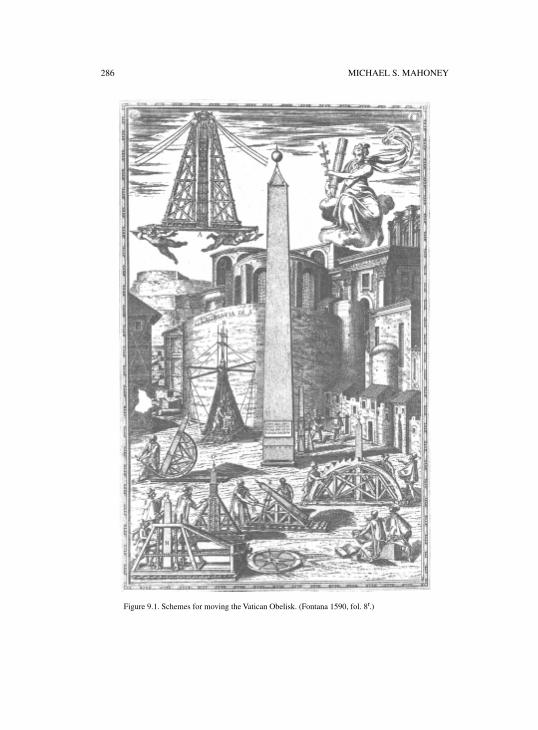
286 MICHAEL S. MAHONEY
Figure 9.1. Schemes for moving the Vatican Obelisk. (Fontana 1590, fol. 8r.)
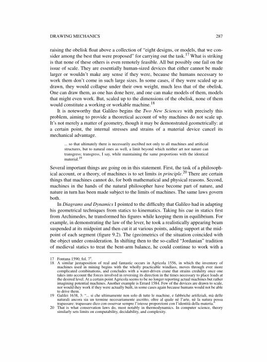
DRAWING MECHANICS 287
raising the obelisk float above a collection of “eight designs, or models, that we con-sider among the best that were proposed” for carrying out the task.17 What is strikingis that none of these others is even remotely feasible. All but possibly one fail on theissue of scale. They are essentially human-sized devices that either cannot be madelarger or wouldn’t make any sense if they were, because the humans necessary towork them don’t come in such large sizes. In some cases, if they were scaled up asdrawn, they would collapse under their own weight, much less that of the obelisk.One can draw them, as one has done here, and one can make models of them, modelsthat might even work. But, scaled up to the dimensions of the obelisk, none of themwould constitute a working or workable machine.18
It is noteworthy that Galileo begins the Two New Sciences with precisely thisproblem, aiming to provide a theoretical account of why machines do not scale up.It’s not merely a matter of geometry, though it may be demonstrated geometrically: ata certain point, the internal stresses and strains of a material device cancel itsmechanical advantage.
... so that ultimately there is necessarily ascribed not only to all machines and artificialstructures, but to natural ones as well, a limit beyond which neither art nor nature cantransgress; transgress, I say, while maintaining the same proportions with the identicalmaterial.19
Several important things are going on in this statement. First, the task of a philosoph-ical account, or a theory, of machines is to set limits in principle.20 There are certainthings that machines cannot do, for both mathematical and physical reasons. Second,machines in the hands of the natural philosopher have become part of nature, andnature in turn has been made subject to the limits of machines. The same laws governboth.
In Diagrams and Dynamics I pointed to the difficulty that Galileo had in adaptinghis geometrical techniques from statics to kinematics. Taking his cue in statics firstfrom Archimedes, he transformed his figures while keeping them in equilibrium. Forexample, in demonstrating the law of the lever, he took a realistically appearing beamsuspended at its midpoint and then cut it at various points, adding support at the mid-point of each segment (figure 9.2). The (geo)metrics of the situation coincided withthe object under consideration. In shifting then to the so-called “Jordanian” traditionof medieval statics to treat the bent-arm balance, he could continue to work with a
17 Fontana 1590, fol. 7v.18 A similar juxtaposition of real and fantastic occurs in Agricola 1556, in which the inventory of
machines used in mining begins with the wholly practicable windlass, moves through ever morecomplicated combinations, and concludes with a water-driven crane that strains credulity once onetakes into account the forces involved in reversing its direction in the times necessary to place loads atthe desired level. At a certain point Agricola seems to be no longer reporting actual machines but ratherimagining potential machines. Another example is Errard 1584. Few of the devices are drawn to scale,nor would they work if they were actually built, in some cases again because humans would not be ableto drive them.
19 Galilei 1638, 3: “... si che ultimamente non solo di tutte le machine, e fabbriche artifiziali, mà dellenaturali ancora sia un termine necesariamente ascritto, oltre al quale nè l’arte, nè la natura possatrapassare: trapassare dico con osservar sempre l’istesse proporzioni con l’identità della materia.”
20 That is what conservation laws do, most notably in thermodynamics. In computer science, theorysimilarly sets limits on computability, decidability, and complexity.
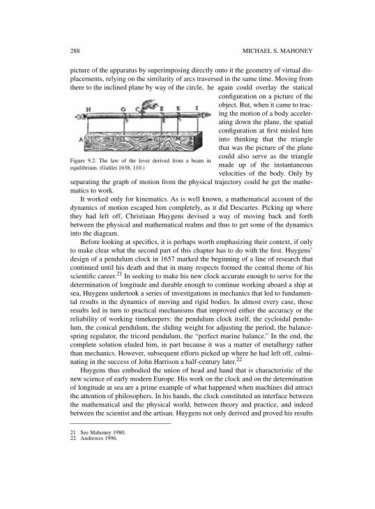
288 MICHAEL S. MAHONEY
picture of the apparatus by superimposing directly onto it the geometry of virtual dis-placements, relying on the similarity of arcs traversed in the same time. Moving fromthere to the inclined plane by way of the circle, he again could overlay the statical
configuration on a picture of theobject. But, when it came to trac-ing the motion of a body acceler-ating down the plane, the spatialconfiguration at first misled himinto thinking that the trianglethat was the picture of the planecould also serve as the trianglemade up of the instantaneousvelocities of the body. Only by
separating the graph of motion from the physical trajectory could he get the mathe-matics to work.
It worked only for kinematics. As is well known, a mathematical account of thedynamics of motion escaped him completely, as it did Descartes. Picking up wherethey had left off, Christiaan Huygens devised a way of moving back and forthbetween the physical and mathematical realms and thus to get some of the dynamicsinto the diagram.
Before looking at specifics, it is perhaps worth emphasizing their context, if onlyto make clear what the second part of this chapter has to do with the first. Huygens’design of a pendulum clock in 1657 marked the beginning of a line of research thatcontinued until his death and that in many respects formed the central theme of hisscientific career.21 In seeking to make his new clock accurate enough to serve for thedetermination of longitude and durable enough to continue working aboard a ship atsea, Huygens undertook a series of investigations in mechanics that led to fundamen-tal results in the dynamics of moving and rigid bodies. In almost every case, thoseresults led in turn to practical mechanisms that improved either the accuracy or thereliability of working timekeepers: the pendulum clock itself, the cycloidal pendu-lum, the conical pendulum, the sliding weight for adjusting the period, the balance-spring regulator, the tricord pendulum, the “perfect marine balance.” In the end, thecomplete solution eluded him, in part because it was a matter of metallurgy ratherthan mechanics. However, subsequent efforts picked up where he had left off, culmi-nating in the success of John Harrison a half-century later.22
Huygens thus embodied the union of head and hand that is characteristic of thenew science of early modern Europe. His work on the clock and on the determinationof longitude at sea are a prime example of what happened when machines did attractthe attention of philosophers. In his hands, the clock constituted an interface betweenthe mathematical and the physical world, between theory and practice, and indeedbetween the scientist and the artisan. Huygens not only derived and proved his results
21 See Mahoney 1980.22 Andrewes 1996.
Figure 9.2. The law of the lever derived from a beam inequilibrium. (Galilei 1638, 110.)
DRAWING MECHANICS 289
in theory, he also designed mechanisms to implement them in practice. He made hisown sketches and, in some cases, built working models. But for the finished producthe had to turn to master clockmakers and establish productive relations with them. Inthis he was less successful, in large part because of his inability or unwillingness torecognize the knowledge they brought to the collaboration along with their skill.
Three aspects of Huygens’ work warrant closer attention: his use of diagrams inhis mechanical investigations, his use of sketches in designing mechanisms, and hisrelations with his clockmakers. On close examination, his drawings reveal a subtleoverlaying of three levels of pictorial representation and establish a visual interfacebetween the physical and the mathematical. That same interface can be found inNewton’s Principia, and its disappearance in later treatises marks the transition to analgebraic mode of analysis. Huygens’ sketches range from the roughest outline todetailed plans, as they show him moving back and forth between theoretical inquiryand practical design. His famous dispute with his Parisian clockmaker, Isaac Thuret,shows what Huygens deemed to count as intellectual property and who could layclaim to possessing it.
3. THE PENDULUM AND THE CYCLOID
In December 1659 Huygens undertook to determine the period of a simple pendu-lum23 or, as he put it, “What ratio does the time of a minimal oscillation of a pendu-lum have to the time of perpendicular fall from the height of the pendulum?” He
23 For a detailed account of what follows, see Mahoney 2000, 17–39.
Figure 9.3. Huygens’ original diagram. (Huygens 1888–1950, XVI 392.)
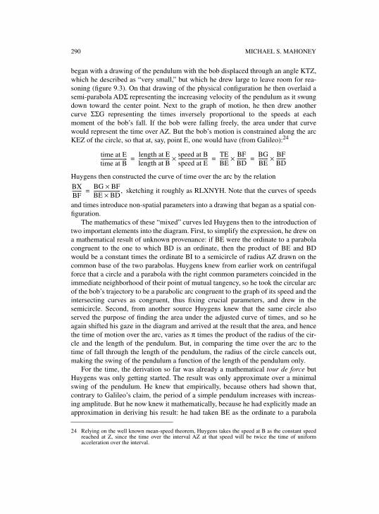
290 MICHAEL S. MAHONEY
began with a drawing of the pendulum with the bob displaced through an angle KTZ,which he described as “very small,” but which he drew large to leave room for rea-soning (figure 9.3). On that drawing of the physical configuration he then overlaid asemi-parabola ADΣ representing the increasing velocity of the pendulum as it swungdown toward the center point. Next to the graph of motion, he then drew anothercurve ΣΣG representing the times inversely proportional to the speeds at eachmoment of the bob’s fall. If the bob were falling freely, the area under that curvewould represent the time over AZ. But the bob’s motion is constrained along the arcKEZ of the circle, so that at, say, point E, one would have (from Galileo):24
Huygens then constructed the curve of time over the arc by the relation
sketching it roughly as RLXNYH. Note that the curves of speeds
and times introduce non-spatial parameters into a drawing that began as a spatial con-figuration.
The mathematics of these “mixed” curves led Huygens then to the introduction oftwo important elements into the diagram. First, to simplify the expression, he drew ona mathematical result of unknown provenance: if BE were the ordinate to a parabolacongruent to the one to which BD is an ordinate, then the product of BE and BDwould be a constant times the ordinate BI to a semicircle of radius AZ drawn on thecommon base of the two parabolas. Huygens knew from earlier work on centrifugalforce that a circle and a parabola with the right common parameters coincided in theimmediate neighborhood of their point of mutual tangency, so he took the circular arcof the bob’s trajectory to be a parabolic arc congruent to the graph of its speed and theintersecting curves as congruent, thus fixing crucial parameters, and drew in thesemicircle. Second, from another source Huygens knew that the same circle alsoserved the purpose of finding the area under the adjusted curve of times, and so heagain shifted his gaze in the diagram and arrived at the result that the area, and hencethe time of motion over the arc, varies as π times the product of the radius of the cir-cle and the length of the pendulum. But, in comparing the time over the arc to thetime of fall through the length of the pendulum, the radius of the circle cancels out,making the swing of the pendulum a function of the length of the pendulum only.
For the time, the derivation so far was already a mathematical tour de force butHuygens was only getting started. The result was only approximate over a minimalswing of the pendulum. He knew that empirically, because others had shown that,contrary to Galileo’s claim, the period of a simple pendulum increases with increas-ing amplitude. But he now knew it mathematically, because he had explicitly made anapproximation in deriving his result: he had taken BE as the ordinate to a parabola
24 Relying on the well known mean-speed theorem, Huygens takes the speed at B as the constant speedreached at Z, since the time over the interval AZ at that speed will be twice the time of uniformacceleration over the interval.
time at Etime at B----------------------
length at Elength at B-------------------------- speed at B
speed at E-------------------------× TE
BE------- BF
BD--------× BG
BE-------- BF
BD--------×= = =
BXBF--------
BG BF×BE BD×----------------------,=
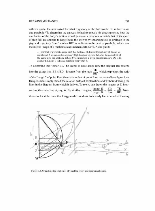
DRAWING MECHANICS 291
rather a circle. He now asked for what trajectory of the bob would BE in fact lie onthat parabola? To determine the answer, he had to unpack his drawing to see how themechanics of the body’s motion would generate a parabola to match that of its speedof free fall. He appears to have found the answer by separating BE as ordinate to thephysical trajectory from “another BE” as ordinate to the desired parabola, which wasthe mirror image of a mathematical (mechanical) curve. As he put it:
... I saw that, if we want a curve such that the times of descent through any of its arcs ter-minating at Z are equal, it is necessary that its nature be such that, if as the normal ET ofthe curve is to the applicate EB, so by construction a given straight line, say, BG is toanother EB, point E falls on a parabola with vertex Z.
To determine that “other BE,” he seems to have asked how the original BE entered
into the expression It came from the ratio which expresses the ratio
of the “length” of point E on the circle to that of point B on the centerline (figure 9.4).Huygens had simply stated the relation without explanation and without drawing thelines in the diagram from which it derives. To see it, one draws the tangent at E, inter-
secting the centerline at, say, W. By similar triangles, Now,
if one looks at the lines that Huygens did not draw but clearly had in mind in forming
BE BD× .TEBE-------,
length Elength B-------------------- EW
BW---------
TEBE-------.= =
Figure 9.4. Unpacking the relation of physical trajectory and mechanical graph.
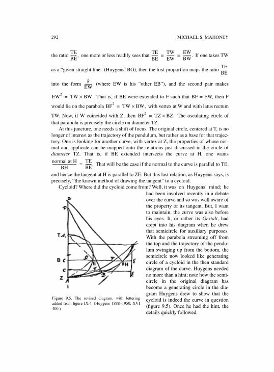
292 MICHAEL S. MAHONEY
the ratio one more or less readily sees that If one takes TW
as a “given straight line” (Huygens’ BG), then the first proportion maps the ratio
into the form (where EW is his “other EB”), and the second pair makes
That is, if BE were extended to F such that BF = EW, then F
would lie on the parabola with vertex at W and with latus rectum
TW. Now, if W coincided with Z, then The osculating circle ofthat parabola is precisely the circle on diameter TZ.
At this juncture, one needs a shift of focus. The original circle, centered at T, is nolonger of interest as the trajectory of the pendulum, but rather as a base for that trajec-tory. One is looking for another curve, with vertex at Z, the properties of whose nor-mal and applicate can be mapped onto the relations just discussed in the circle ofdiameter TZ. That is, if BE extended intersects the curve at H, one wants
That will be the case if the normal to the curve is parallel to TE,
and hence the tangent at H is parallel to ZE. But this last relation, as Huygens says, isprecisely, “the known method of drawing the tangent” to a cycloid.
Cycloid? Where did the cycloid come from? Well, it was on Huygens’ mind; hehad been involved recently in a debateover the curve and so was well aware ofthe property of its tangent. But, I wantto maintain, the curve was also beforehis eyes. It, or rather its Gestalt, hadcrept into his diagram when he drewthat semicircle for auxiliary purposes.With the parabola streaming off fromthe top and the trajectory of the pendu-lum swinging up from the bottom, thesemicircle now looked like generatingcircle of a cycloid in the then standarddiagram of the curve. Huygens neededno more than a hint; note how the semi-circle in the original diagram hasbecome a generating circle in the dia-gram Huygens drew to show that thecycloid is indeed the curve in question(figure 9.5). Once he had the hint, thedetails quickly followed.
TEBE-------, TE
BE------- TW
EW---------
EWBW---------.= =
TEBE-------
kEW---------
EW2 TW BW.×=
BF2 TW BW,×=
BF2 TZ BZ.×=
normal at HBH
----------------------------TEBE-------.=
Figure 9.5. The revised diagram, with letteringadded from figure IX.4. (Huygens 1888–1950, XVI400.)
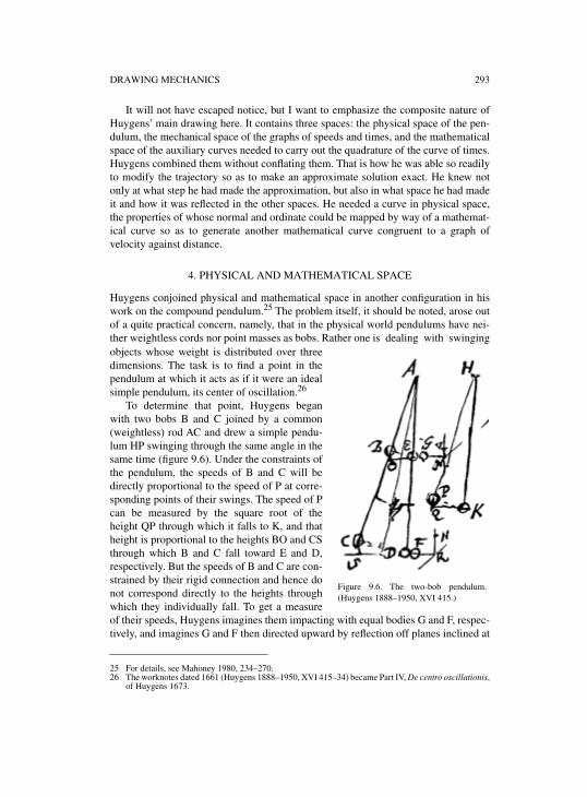
DRAWING MECHANICS 293
It will not have escaped notice, but I want to emphasize the composite nature ofHuygens’ main drawing here. It contains three spaces: the physical space of the pen-dulum, the mechanical space of the graphs of speeds and times, and the mathematicalspace of the auxiliary curves needed to carry out the quadrature of the curve of times.Huygens combined them without conflating them. That is how he was able so readilyto modify the trajectory so as to make an approximate solution exact. He knew notonly at what step he had made the approximation, but also in what space he had madeit and how it was reflected in the other spaces. He needed a curve in physical space,the properties of whose normal and ordinate could be mapped by way of a mathemat-ical curve so as to generate another mathematical curve congruent to a graph ofvelocity against distance.
4. PHYSICAL AND MATHEMATICAL SPACE
Huygens conjoined physical and mathematical space in another configuration in hiswork on the compound pendulum.25 The problem itself, it should be noted, arose outof a quite practical concern, namely, that in the physical world pendulums have nei-ther weightless cords nor point masses as bobs. Rather one is dealing with swingingobjects whose weight is distributed over threedimensions. The task is to find a point in thependulum at which it acts as if it were an idealsimple pendulum, its center of oscillation.26
To determine that point, Huygens beganwith two bobs B and C joined by a common(weightless) rod AC and drew a simple pendu-lum HP swinging through the same angle in thesame time (figure 9.6). Under the constraints ofthe pendulum, the speeds of B and C will bedirectly proportional to the speed of P at corre-sponding points of their swings. The speed of Pcan be measured by the square root of theheight QP through which it falls to K, and thatheight is proportional to the heights BO and CSthrough which B and C fall toward E and D,respectively. But the speeds of B and C are con-strained by their rigid connection and hence donot correspond directly to the heights throughwhich they individually fall. To get a measureof their speeds, Huygens imagines them impacting with equal bodies G and F, respec-tively, and imagines G and F then directed upward by reflection off planes inclined at
25 For details, see Mahoney 1980, 234–270.26 The worknotes dated 1661 (Huygens 1888–1950, XVI 415–34) became Part IV, De centro oscillationis,
of Huygens 1673.
Figure 9.6. The two-bob pendulum.(Huygens 1888–1950, XVI 415.)
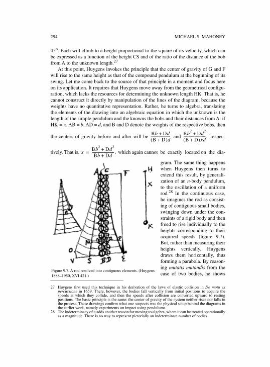
294 MICHAEL S. MAHONEY
45o. Each will climb to a height proportional to the square of its velocity, which canbe expressed as a function of the height CS and of the ratio of the distance of the bobfrom A to the unknown length.27
At this point, Huygens invokes the principle that the center of gravity of G and Fwill rise to the same height as that of the compound pendulum at the beginning of itsswing. Let me come back to the source of that principle in a moment and focus hereon its application. It requires that Huygens move away from the geometrical configu-ration, which lacks the resources for determining the unknown length HK. That is, hecannot construct it directly by manipulation of the lines of the diagram, because theweights have no quantitative representation. Rather, he turns to algebra, translatingthe elements of the drawing into an algebraic equation in which the unknown is thelength of the simple pendulum and the knowns the bobs and their distances from A: ifHK = x, AB = b, AD = d, and B and D denote the weights of the respective bobs, then
the centers of gravity before and after will be and respec-
tively. That is, which again cannot be exactly located on the dia-
gram. The same thing happenswhen Huygens then turns toextend this result, by generali-zation of an n-body pendulum,to the oscillation of a uniformrod.28 In the continuous case,he imagines the rod as consist-ing of contiguous small bodies,swinging down under the con-straints of a rigid body and thenfreed to rise individually to theheights corresponding to theiracquired speeds (figure 9.7).But, rather than measuring theirheights vertically, Huygensdraws them horizontally, thusforming a parabola. By reason-ing mutatis mutandis from thecase of two bodies, he shows
27 Huygens first used this technique in his derivation of the laws of elastic collision in De motu expercussione in 1659. There, however, the bodies fall vertically from initial positions to acquire thespeeds at which they collide, and then the speeds after collision are converted upward to restingpositions. The basic principle is the same: the center of gravity of the system neither rises nor falls inthe process. These drawings confirm what one suspects was the physical setup behind the diagrams inthe earlier work, namely experiments on impact using pendulums.
28 The indeterminacy of n adds another reason for moving to algebra, where it can be treated operationallyas a magnitude. There is no way to represent pictorially an indeterminate number of bodies.
Bb Dd+B D+( )d
----------------------- Bb2 Dd2+B D+( )xd
--------------------------,
xBb2 Dd2+Bb Dd+
--------------------------,=
Figure 9.7. A rod resolved into contiguous elements. (Huygens1888–1950, XVI 421.)
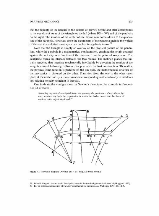
DRAWING MECHANICS 295
that the equality of the heights of the centers of gravity before and after correspondsto the equality of areas of the triangle on the left (where BS = OV) and of the parabolaon the right. The solution of the center of oscillation now comes down to the quadra-ture of the parabola. However, since the parameters of the parabola include the weightof the rod, that solution must again be couched in algebraic terms.29
Note that the triangle is simply an overlay on the physical picture of the pendu-lum, while the parabola is a mathematical configuration, graphing the height attainedagainst the velocity as a function of the distance from the point of suspension. Thecenterline forms an interface between the two realms. The inclined planes that ini-tially rendered that interface mechanically intelligible by directing the motion of theweights upward following collision disappear after the first construction. Thereafter,the physical configuration is pictured on the one side, the mathematical structure ofthe mechanics is pictured on the other. Transition from the one to the other takesplace at the centerline by a transformation corresponding mathematically to Galileo’slaw relating velocity to height in free fall.
One finds similar configurations in Newton’s Principia, for example in Proposi-tion 41 of Book I:
Assuming any sort of centripetal force, and granting the quadrature of curvilinear fig-ures, required are both the trajectories in which the bodies move and the times ofmotions in the trajectories found.30
Figure 9.8. Newton’s diagram. (Newton 1687, I.8, prop. xli probl. xxviii.)
29 Indeed, Huygens had to retain the algebra even in the finished geometrical form of [Huygens 1673].30 For an extended discussion of Newton’s mathematical methods, see Mahoney 1993, 183–205.
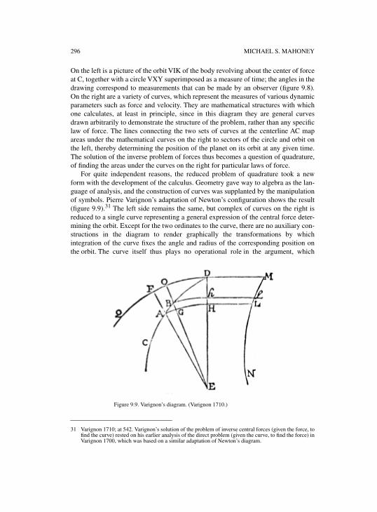
296 MICHAEL S. MAHONEY
On the left is a picture of the orbit VIK of the body revolving about the center of forceat C, together with a circle VXY superimposed as a measure of time; the angles in thedrawing correspond to measurements that can be made by an observer (figure 9.8).On the right are a variety of curves, which represent the measures of various dynamicparameters such as force and velocity. They are mathematical structures with whichone calculates, at least in principle, since in this diagram they are general curvesdrawn arbitrarily to demonstrate the structure of the problem, rather than any specificlaw of force. The lines connecting the two sets of curves at the centerline AC mapareas under the mathematical curves on the right to sectors of the circle and orbit onthe left, thereby determining the position of the planet on its orbit at any given time.The solution of the inverse problem of forces thus becomes a question of quadrature,of finding the areas under the curves on the right for particular laws of force.
For quite independent reasons, the reduced problem of quadrature took a newform with the development of the calculus. Geometry gave way to algebra as the lan-guage of analysis, and the construction of curves was supplanted by the manipulationof symbols. Pierre Varignon’s adaptation of Newton’s configuration shows the result(figure 9.9).31 The left side remains the same, but complex of curves on the right isreduced to a single curve representing a general expression of the central force deter-mining the orbit. Except for the two ordinates to the curve, there are no auxiliary con-structions in the diagram to render graphically the transformations by whichintegration of the curve fixes the angle and radius of the corresponding position onthe orbit. The curve itself thus plays no operational role in the argument, which
31 Varignon 1710; at 542. Varignon’s solution of the problem of inverse central forces (given the force, tofind the curve) rested on his earlier analysis of the direct problem (given the curve, to find the force) inVarignon 1700, which was based on a similar adaptation of Newton’s diagram.
Figure 9.9. Varignon’s diagram. (Varignon 1710.)
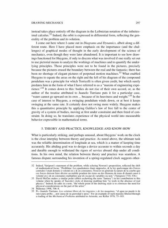
DRAWING MECHANICS 297
instead takes place entirely off the diagram in the Leibnizian notation of the infinites-imal calculus.32 Indeed, the orbit is expressed in differential form, reflecting the gen-erality of the problem and its solution.
I come out here where I came out in Diagrams and Dynamics, albeit along a dif-ferent route. Here I have placed more emphasis on the importance (and the chal-lenges) of graphical modes of thought in the early development of the science ofmechanics, even though they were later abandoned. It is important to see how draw-ings functioned for Huygens, if only to discern what was involved if one really set outto use pictorial means to analyze the workings of machines and to quantify the under-lying principles. Those principles were not to be found in the pictures, preciselybecause the pictures erased the boundary between the real and the fantastic; there hasbeen no shortage of elegant pictures of perpetual motion machines.33 What enabledHuygens to equate the areas on the right and the left of his diagram of the compoundpendulum was a principle for which Torricelli is often given credit, but which surelypredates him in the form of what I have referred to as a “maxim of engineering expe-rience.”34 It comes down to this: bodies do not rise of their own accord, or, as theauthor of the treatise attributed to Juanelo Turriano puts it for a particular case,“water cannot go upward on its own ... because of its heaviness and weight.”35 In thecase of interest to Huygens, a swinging pendulum winds down, or at best it keepsswinging at the same rate. It certainly does not swing more widely. Huygens makesthis a quantitative principle by applying Galileo’s law of free fall to the center ofgravity of a system of bodies, moving at first under constraint and then freed of con-straint. In doing so, he translates experience of the physical world into measurablebehavior expressible in mathematical terms.
5. THEORY AND PRACTICE, KNOWLEDGE AND KNOW-HOW
What is particularly striking, and perhaps unusual, about Huygens’ work on the clockis the close interplay between theory and practice. As noted above, the ultimate taskwas the reliable determination of longitude at sea, which is a matter of keeping timeaccurately. His abiding goal was to design a device accurate to within seconds a dayand durable enough to withstand the rigors of service aboard ship under all condi-tions. In his own mind, the relation between theory and practice was seamless. Afamous dispute surrounding his invention of a spring-regulated clock suggests other-
32 Indeed, Varignon’s statement of the problem, while echoing Newton’s proposition, reflected the shiftof mathematical focus: “Problême: Les quadratures étant supposées, & la loy quelconque des Forcescentrales f etant donnée à volonté en y & en constantes; Trouver en générale la nature de la courbe queces forces doivent faire décrire au mobile pendent des tems ou des élemens de tems dt donnés aussi àvolonté en y & en constantes multipliées par dx ou par dz variables ou non.” (Varignon 1710, 536.)
33 David McGee makes a similar point (albeit eschewing the term “fantasy”) in his contribution to thisvolume when he speaks of Taccola’s style of drawing enabling him “to work in the absence of realphysics.” Indeed, he adds in a note, “the whole point of the drawing style is to eliminate the need forphysical considerations on the part of the artist.”
34 Mahoney 1998, 706–8.35 Ps.–Juanelo Turriano, Los veintiun libros de los ingenios y de las maquinas, “el agua no puede ir de
suyo para arriba ... por causa de su gravedad y peso.” For an example of such maxims filtered througha reading of the Mechanical Problems attributed to Aristotle, see Keller 1976, 75–103.
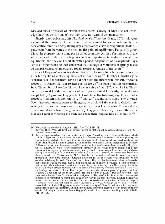
298 MICHAEL S. MAHONEY
wise and raises a question of interest in this context, namely, of what kinds of knowl-edge drawings contain and of how they serve as means of communication.
Shortly after publishing his Horologium Oscillatorium (Paris, 1673), Huygensuncovered the property of the cycloid that accounted for its tautochronicity: theaccelerative force on a body sliding down the inverted curve is proportional to its dis-placement from the vertex at the bottom, the point of equilibrium. He quickly gener-alized the property into a principle he called incitation parfaite décroissante: in anysituation in which the force acting on a body is proportional to its displacement fromequilibrium, the body will oscillate with a period independent of its amplitude. By aseries of experiments he then confirmed that the regular vibrations of springs restedon that principle and immediately sought to take advantage of the result.36
One of Huygens’ worknotes shows that on 20 January 1675 he devised a mecha-nism for regulating a clock by means of a spiral spring.37 Or rather I should say hesketched such a mechanism, for he did not build the mechanism himself, or even amodel of it. Rather, he later related that on the 21st he sought out his clockmaker,Isaac Thuret, but did not find him until the morning of the 22nd, when he had Thuretconstruct a model of the mechanism while Huygens waited. Evidently, the model wascompleted by 3 p.m., and Huygens took it with him. The following day, Thuret built amodel for himself and then on the 24th and 25th undertook to apply it to a watch.Soon thereafter, unbeknownst to Huygens, he displayed the watch to Colbert, pre-senting it in a such a manner as to suggest that it was his invention. Dismayed thatThuret would so violate a pledge of secrecy, Huygens vehemently rejected the claim,accused Thuret of violating his trust, and ended their longstanding collaboration.38
36 Worknotes and sketches in Huygens 1888–1950, XVIII 489–98. 37 Huygens 1888–1950, VII 408ff; on Huygens’ invention of the spiral balance, see Leopold 1980, 221–
233 and Leopold 1982.38 Huygens appears to have had grounds for being angry. According to his version of the facts, which
Thuret’s supporters did not contest, Huygens had pledged Thuret to secrecy before explaining themechanism he wished to have built. Over the following week, Huygens did more work on the designas he planned both its announcement to the scientific community and its presentation to MinisterColbert for the purpose of securing a privilège restricting its manufacture to those licensed by Huygens.On 30 January, he wrote Henry Oldenburg, secretary of the Royal Society, announcing a newmechanism for regulating watches accurately enough to determine longitude and encoding its basicprinciple in an anagram. The next day he visited Colbert. On 1 February, he learned that Thuret hadalready attended the Minister on the 24th to show him the second model and that people were nowspeaking of Thuret as the inventor. Thuret had said nothing of this to Huygens, even though the two hadcollaborated during the week. Thuret had made hints to Huygens that he desired a share in the credit.But Huygens rejected the idea, even as he pointed out that in enjoying Huygens’ license to producewatches with the mechanism Thuret stood to reap the greater monetary gain. On learning of what hetook as a betrayal of trust, Huygens cut off all relations with Thuret, excluding him from a license. Asthe leading clockmaker of Paris, Thuret enjoyed the protection of some powerful patrons, not leastMadame Colbert and her son-in law, Charles Honoré d’Albert de Luynes, Duc de Chevreuse. Theirintercession led to Thuret’s written acknowledgment of Huygens’ sole claim to the invention andexpression of regret that he might have acted in any way to suggest otherwise. In return he receivedauthorization to produce the new watches. But, then, so too did all clockmakers in Paris, as Huygensdecided not to ask the Parlement de Paris to register his privilège. Although the two men eventuallyreconciled, and indeed Huygens recognized the superiority of Thuret’s craftsmanship, they neverresumed their active collaboration, which had constituted a powerful creative force in timekeeping. Fordetails of the dispute, which dominated Huygens’ attention for six months, see Huygens 1888–1950,VII 405–498.
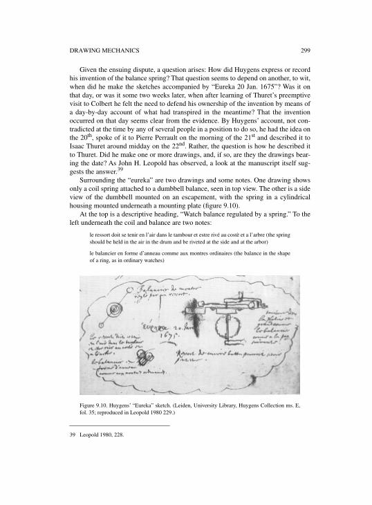
DRAWING MECHANICS 299
Given the ensuing dispute, a question arises: How did Huygens express or recordhis invention of the balance spring? That question seems to depend on another, to wit,when did he make the sketches accompanied by “Eureka 20 Jan. 1675”? Was it onthat day, or was it some two weeks later, when after learning of Thuret’s preemptivevisit to Colbert he felt the need to defend his ownership of the invention by means ofa day-by-day account of what had transpired in the meantime? That the inventionoccurred on that day seems clear from the evidence. By Huygens’ account, not con-tradicted at the time by any of several people in a position to do so, he had the idea onthe 20th, spoke of it to Pierre Perrault on the morning of the 21st and described it toIsaac Thuret around midday on the 22nd. Rather, the question is how he described itto Thuret. Did he make one or more drawings, and, if so, are they the drawings bear-ing the date? As John H. Leopold has observed, a look at the manuscript itself sug-gests the answer.39
Surrounding the “eureka” are two drawings and some notes. One drawing showsonly a coil spring attached to a dumbbell balance, seen in top view. The other is a sideview of the dumbbell mounted on an escapement, with the spring in a cylindricalhousing mounted underneath a mounting plate (figure 9.10).
At the top is a descriptive heading, “Watch balance regulated by a spring.” To theleft underneath the coil and balance are two notes:
le ressort doit se tenir en l’air dans le tambour et estre rivé au costè et a l’arbre (the springshould be held in the air in the drum and be riveted at the side and at the arbor)
le balancier en forme d’anneau comme aux montres ordinaires (the balance in the shapeof a ring, as in ordinary watches)
39 Leopold 1980, 228.
Figure 9.10. Huygens’ “Eureka” sketch. (Leiden, University Library, Huygens Collection ms. E,fol. 35; reproduced in Leopold 1980 229.)
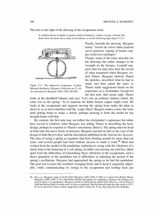
300 MICHAEL S. MAHONEY
The note to the right of the drawing of the escapement reads:
le tambour dessus la platine et grand comme le balancier, comme a la pag. suivante (thedrum above the plate and as large as the balance, as on the following page (figure 9.11))
Finally, beneath the drawing, Huygensnoted, “ressort de cuivre battu pourroitservir peutestre (spring of beaten cop-per could serve perhaps).”Clearly, some of the notes describe notthe drawings but rather changes to bewrought on the designs. Leopold sug-gests that we may have here the recordof what transpired when Huygens vis-ited Thuret. Huygens showed Thurethis sketches, described what he had inmind, and then jotted the notes asThuret made suggestions based on hisexperience as a clockmaker. Except forthe first note, that seems right. Thuret
looks at the dumbbell balance and says “Let’s use an ordinary balance wheel, thesame size as the spring.” As to material, he thinks beaten copper might work. Helooks at the escapement and suggests moving the spring from under the plate toabove it, so as not to interfere with the ‘scape wheel. Huygens makes a note, but waitsuntil getting home to make a sketch, perhaps drawing it from the model he hasbrought home with him.
By contrast, the first note may not reflect the clockmaker’s experience but ratherhave served to reinforce what Huygens was telling Thuret in describing the basicdesign, perhaps in response to Thuret’s uncertainty about it. The spring must be fixedat both ends but move freely in between. Huygens insisted on that as the core of thedesign in both the privilège and the description published in the Journal des Sçavans.The idea of using a spring as regulator had been floating around for more than tenyears, and several people had tried without success to make it work.40 Most hadworked from the model of the pendulum, replacing its swing with the vibrations of ametal strip or the bouncing of a coil spring, in either case leaving one end free. Quiteapart from the difficulties of transmitting those vibrations to the escapement, such adirect quotation of the pendulum led to difficulties in adjusting the period of thespring’s oscillations. Huygens had approached the spring as he had the pendulum.The goal was to leave the oscillator swinging freely and to keep it separately adjust-able, while communicating its swings to the escapement and feeding back just
40 See, e.g., Huygens’ reply of 18.IX.1665 (Huygens 1888–1950, V 486) to a report from Robert Moray(Huygens 1888–1950, V 427) that Robert Hooke had spoken of “applying a spring to the balance of aclock in place of a pendulum.” Huygens said he recalled having heard of the idea on a visit to Paris in1660 but did not think it would work, at least as proposed. Having himself made the idea work in 1675,he never adverted to those earlier suggestions and to what role, if any, they played in his thinking.
Figure 9.11. The improved escapement. (Leiden,Museum Boerhaave, Huygens Collection ms. E, fol.36; reproduced in Huygens 1888–1950, VII 409.)
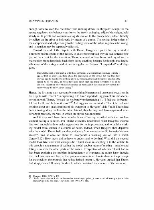
DRAWING MECHANICS 301
enough force to keep the oscillator from running down. In Huygens’ design for thespring regulator, the balance constitutes the freely swinging, adjustable weight, heldsteady in its pivots and communicating its motion to the escapement, either directlyby pallets on the arbor or indirectly by means of a pinion. The spring, independent ofthe escapement and subject only to the coiling force of the arbor, regulates the swing,and its tension may be separately adjusted.
Toward the end of the dispute with Thuret, Huygens reported having remindedThuret of just this point of the design. In an effort to explain why he had sought somepart of the credit for the invention, Thuret claimed to have been thinking of such amechanism but to have held back from doing anything because he thought that lateralvibrations of the spring would vitiate its regular oscillations. “I responded,” said Huy-gens,
that what he said of the trouble with these vibrations was something contrived to make itappear that he knew something about the application of the spring, but that this itselfshowed that he had known nothing about it, because, if he had thought of attaching thespring by its two ends, he would have also easily seen that these vibrations were of noconcern, occurring only when one knocked or beat against the clock and even then notundercutting the effect of the spring.41
Hence, the first note may account for something Huygens said on several occasions inhis dispute with Thuret. “In explaining it to him,” reported Huygens of his initial con-versation with Thuret, “he said (as yet barely understanding it), ‘I find that so beauti-ful that I still can’t believe it is so.’”42 As Huygens later reminded Thuret, he had saidnothing about any investigations of his own prior to Huygens’ visit. Yet, if Thuret hadbeen thinking along the lines he later claimed, then he may well have expressed won-der about precisely the way in which the spring was mounted.
And it may well have been wonder born of having wrestled with the problemwithout seeing a solution. For Thuret evidently understood what Huygens showedhim well enough both to make suggestions for its improvement and to build a work-ing model from scratch in a couple of hours. Indeed, when Huygens then departedwith the model, Thuret built another, evidently from memory (or did he make his ownsketch?), and at once set about to incorporate a working version into a watch(figure 8.12). How much did he have to understand to do that? What did the secondmodel look like, and what changes did Thuret make in adapting it to the watch? Inthis case, it is not a matter of scaling the model up, but rather of making it smaller andfitting it in with the other parts of the watch. Irrespective of whether Thuret had infact been exploring the problem independently of Huygens, he might have thoughtthat the know-how involved in that process alone entitled him to share in the privilegefor the clock on the grounds that he had helped invent it. Huygens argued that Thurethad simply been following his sketch, which contained the essence of the invention.
41 Huygens 1888–1950, V 486.42 “En la luy expliquant il dit, ne l’entendant encore qu’a peine, je trouve cela si beau que je me défie
tousjours qu’il ne soit ainsi.” Huygens 1888–1950, VII 410.
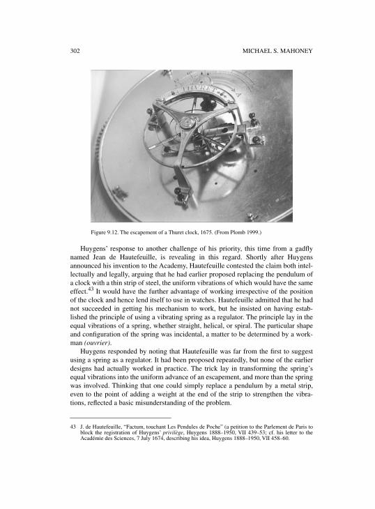
302 MICHAEL S. MAHONEY
Huygens’ response to another challenge of his priority, this time from a gadflynamed Jean de Hautefeuille, is revealing in this regard. Shortly after Huygensannounced his invention to the Academy, Hautefeuille contested the claim both intel-lectually and legally, arguing that he had earlier proposed replacing the pendulum ofa clock with a thin strip of steel, the uniform vibrations of which would have the sameeffect.43 It would have the further advantage of working irrespective of the positionof the clock and hence lend itself to use in watches. Hautefeuille admitted that he hadnot succeeded in getting his mechanism to work, but he insisted on having estab-lished the principle of using a vibrating spring as a regulator. The principle lay in theequal vibrations of a spring, whether straight, helical, or spiral. The particular shapeand configuration of the spring was incidental, a matter to be determined by a work-man (ouvrier).
Huygens responded by noting that Hautefeuille was far from the first to suggestusing a spring as a regulator. It had been proposed repeatedly, but none of the earlierdesigns had actually worked in practice. The trick lay in transforming the spring’sequal vibrations into the uniform advance of an escapement, and more than the springwas involved. Thinking that one could simply replace a pendulum by a metal strip,even to the point of adding a weight at the end of the strip to strengthen the vibra-tions, reflected a basic misunderstanding of the problem.
43 J. de Hautefeuille, “Factum, touchant Les Pendules de Poche” (a petition to the Parlement de Paris toblock the registration of Huygens’ privilège, Huygens 1888–1950, VII 439–53; cf. his letter to theAcadémie des Sciences, 7 July 1674, describing his idea, Huygens 1888–1950, VII 458–60.
Figure 9.12. The escapement of a Thuret clock, 1675. (From Plomb 1999.)
DRAWING MECHANICS 303
Huygens’ claim to the invention of the balance-spring regulator rested on two dif-ferent sorts of knowledge. First, he knew in principle that a spring, whatever its form,was a tautochronic oscillator. That meant more than knowing for a fact that springsvibrate at the same rate no matter how much they are stretched or compressed. Itmeant knowing why that was the case. His letter to the Journal des Sçavans announc-ing the invention spoke of the movement of the clock as being “regulated by a princi-ple of equality, just as that of pendulums is corrected by the cycloid.”44 That piece ofknowledge stemmed from his researches of 1673–74. As a result he knew that therelation between a spring and a cycloidal pendulum lay in their both instantiating theprinciple that the driving force is directly proportional to the distance from rest. Theyare different manifestations of the same kind of motion.
Second, Huygens had determined the particular arrangement that translated theprinciple into practice for the spring. As in the case of the pendulum, it was a matterof letting a weight swing freely, driven ever so slightly by the force of the drivingweight or mainspring, communicated through the escapement. Hanging the pendu-lum by a cord attached to the frame, and connecting it to the escapement by means ofa crutch, had been the key to using it to regulate the clock while using the clock tokeep the pendulum swinging. In the case of the spring regulator, the weight was thebalance wheel, pivoting about the arbor as an axis and governed by the winding andunwinding of a spiral spring attached at one end to the arbor and at the other to theplate or support on which the arbor was mounted. While his original drawingsshowed the arbor with pallets directly in contact with the crown wheel, the versionfor the Journal des Sçavans showed a pinion moving a rack wheel, which turned thepallets connected with the crown wheel. That design quoted the arrangement in hisoriginal clock of 1658.
What Hautefeuille thought was a mere “accident,” a technicality to be left to arti-san, Huygens considered essential. It was the weight of the balance wheel that heldback the advance of the escapement. Since the wheel was swinging about its center ofgravity, its motion was independent of its position in space. The spring maintainedthe tautochrony of that motion. Neither component could do the job alone, yet theycould be independently adjusted for the force of the mainspring and the period ofoscillation. The secret of a “regular, portable” timepiece lay in their combination.
For present purposes, the rights and wrongs of Huygens’ dispute with Thuret arethe least interesting aspect of the episode. What is more interesting is the intersectionof craft knowledge and high science, of what one knew from building mechanismsand what one knew from analyzing their dynamics. Regrettably, only the latterknowledge was self-consciously set down in words; we have only Huygens’ accountof this affair. For the former, we must reason indirectly from the artifacts, something Imust leave to the antique horologists who know enough about clockmaking to do itcritically.45 In the case of Renaissance machines we also lack the high science. But
44 .Journal des Sçavans, 25.II.1675; repr. in Huygens 1888–1950, VII 424–5; at 424: “... leur [sc. leshorologes] mouvement est reglé par un principe d’égalité, de même qu’est celuy des pendules corrigépar la Cycloïde.”
304 MICHAEL S. MAHONEY
we do have the drawings and must find ways to reconstruct from them and, with thehelp of modern craft expertise, from the artifacts, the conceptual framework of theartisans a half-millennium ago.
Also interesting is the direction Huygens took subsequently. The spring balance,it turned out, had its deficiencies. The practical goal of the enterprise was an accuratesea-going clock for determining longitude. While the spring was mechanically morestable than a pendulum, it was sensitive to changes in temperature and humidity to adegree that undermined its accuracy. So Huygens pursued other mechanisms, all ofwhich had in common the underlying mechanical principle of the spring: the forcedriving them varied as the displacement from equilibrium. They were all what subse-quently came to be called simple harmonic oscillators. Sketches for such mechanismsrun for pages in his works, most accompanied by mathematical demonstrations oftheir workings. In some instances, it is not clear how they would be incorporated in aclock. In other cases, the designs were in fact realized. In the two best knowninstances, his tricord pendulum and his “perfect marine balance,” Huygens built amodel before turning to a clockmaker to produce a working timepiece.46 In bothcases, the model seems to have been a necessary proof of concept before attempting afull-scale clock.
What does this all have to do with the topic of this volume? Two things, I think.First, it shows that just drawing a picture of a device, however realistic the rendering,does not suffice to explain how it works. What it conveys depends to a large extent onwhat knowledge the viewer brings to it. As Huygens tells it, at least, Thuret built amodel of the spring balance from Huygens’ drawing without understanding how itworked. But having built one model and having heard Huygens’ explanation, he evi-dently knew enough about the workings of the device to adapt it to a watch. That is,Thuret knew what he could change and what not; he knew how to scale it to his ownneeds. But he went beyond that. He claimed a share in the credit for the invention onthe grounds that he had transformed Huygens’ idea into a working device. If theinterpretation above of what occurred between the two men is correct, Huygens’drawing did not suffice for that; it required a clockmaker’s knowledge of the field ofapplication. To Huygens’ way of thinking, the invention lay in the idea. For allThuret’s expert knowledge, he had not understood at first why it worked.
45 On this point, see Mahoney 1996, 63–68. The several articles in that volume on the clocks of JohnHarrison are brilliant examples of such direct “readings” of the artifacts.
46 Huygens seems to have drawn a lesson from his experience with Thuret. In his “Application deDécembre 1683” he wrote: “Le 17 dec. 1683 j’ay portè [sic] a Van Ceulen l’horologer le modelle quej’avois fait de ce mouvement de Pendule Cylindrique, pour changer de cette facon les 2 horologes queje luy avois fait faire our la Compagnie des Indes Orientales. J’avois prié mon frere de Zeelhem de veniravec moy: parce que ledit horologer s’imaginoit d’avoir trouvé la mesme chose que moy, apres m’enavoir ouy dire quelque chose en gros. Mais ayant vu le modelle il avoua que ce qu’il avoit modelé n’yressembloit nullement.” (Huygens 1888–1950, XVIII 532) Here a comparison of models seems to haveprevented confusion between what Huygens and Van Ceulen had in mind respectively and suggests thata drawing such as the one Huygens had earlier made for Thuret might have been too vague or, literally,sketchy to do so.

DRAWING MECHANICS 305
6. MATHEMATICAL MODELS
That difference of perspective leads to the second point. By the late seventeenth cen-tury, two kinds of people were emerging from the machine literature of the Renais-sance, those concerned with machines and those concerned with (mathematical)mechanics. What Thuret, the craftsman, built was a model of a specific mechanism, acoiled-spring balance. From that point on, he was interested in the various ways inwhich it could be used in watches and clocks. As was the case for his counterparts inEngland, his clockmaking skills recommended him as an instrument maker for thenew scientific institutions. In the following century, clockmakers built the first textilemachinery. In short, artisans like Thuret became machine builders, for whom a newgenre of machine literature would develop in the nineteenth century.47
What Huygens, the mathematician, showed Thuret was a model of a general prin-ciple, “perfect incitation.” For Huygens the spring balance was one of a series ofmodels that began with the cycloidal pendulum and included the vibrating string, thespring, and the variety of forms of the “perfect marine balance.” Once he had discov-ered the principle, he began to look for the ways in which it was instantiated in phys-ical systems. His drawings of those systems all aimed at bringing out theproportionality between the accelerative force and the displacement from equilib-rium. In some cases, it emerged more or less directly, as in the case of chains beinglifted from a surface or of cylinders being raised and lowered in containers of mer-cury. In other cases, it took some sophisticated and ingenious manipulation to relatethe geometry of the mechanism to that of the cycloid. Later mechanicians would seekit symbolically by reducing the equation of the system to the form
To work that way is to build a model of another sort, namely a mathematical model,in which one seeks to map a physical system onto a deductive structure. As Newtonshowed, using the same mechanics as Huygens but positing another kind of incita-tion, one in which the accelerative force varies as the inverse square of the distance,unites Kepler’s empirically derived laws of planetary motion in a mathematical struc-ture, of which Galileo’s laws of local motion are limiting cases. In a second set of“Queries” added to his Opticks in 1713, he turned his attention to the chemical andelectrical properties of bodies and wondered rhetorically whether they might not beexplained in terms of small particles of matter attracting and repelling one another bycentral forces of a different sort from gravity. “And thus Nature will be very conform-able to her self,” he mused, “and very simple, performing all the great Motions of theheavenly Bodies by the Attraction of Gravity which intercedes those Bodies, andalmost all the small ones of their Particles by some other attractive and repelling
47 In England, the great clock and instrument makers could aspire to learned status, as Richard Sorrensonhas shown in his dissertation [Sorrenson 1993]; for an example of one such clockmaker, see Sorrenson1996.
F md2S
dt2-------- kS.–= =
306 MICHAEL S. MAHONEY
Powers which intercede the particles.”48 His suggestion became the agenda of mathe-matical physics for the next two centuries, as practitioners sought to apply theincreasingly sophisticated resources of analytic mechanics to mechanical models ofnatural phenomena. Following that agenda into the late twentieth century and to itsencounter with complexity leads to a new problem of scaling and to what appears tobe a redefinition of the relation of mathematics to nature. But that issue really wouldtake this contribution beyond the question of the pictorial means of early modernengineering.
48 Newton 1730, 396.
APPENDIX

CONTRIBUTORS
Filippo CamerotaIstituto e Museo di Storia della ScienzaFlorence, Italy
Mary Henninger-VossIndependent scholarCamp Hill, Pennsylvania, U.S.A.
Wolfgang LefèvreMax Planck Institute for the History of ScienceBerlin, Germany
Rainer LengInstitut für GeschichteUniversität WürzburgWürzburg, Germany
Pamela O. LongIndependent scholarWashington, D.C., U.S.A.
David McGeeDibner InstituteCambridge, Massachusetts, U.S.A.
Michael S. MahoneyHistory of Science DepartmentPrinceton UniversityPrinceton, New Jersey, U.S.A.
Jeanne PeifferCentre Alexandre KoyréParis, France
Marcus PopplowLehrstuhl für Technikgeschichte BTU CottbusCottbus, Germany

REFERENCES
UNPUBLISHED SOURCES
Cologne. W* 232 – Konrad Kyeser ‘Bellifortis’. Archiv der Stadt Köln.Dresden. C 363 – Veitt Wolff von Senfftenberg ‘hantbiechlin vnd ausszug von meinen
erfindungen’. Staats- und Universitätsbibliothek Dresden.Erlangen. Ms. B. 26 – Ludwig von Eyb ‘Kriegsbuch’. Universitätsbibliothek Erlangen-
Nürnberg.Florence. Archivio Privato di D. Giov. De Medici, Filza 8. Archivio di Stato Firenze.———. Ashburnham ms. 1212 – Matteo Zaccolini ‘Della Descritione dell’ombre prodotte
de’corpi opachi rettilinei (1617–1622)’, ‘Prospettiva lineale, De’colori’ and ‘Prospettivadel Colore’. Biblioteca Medicea Laurenziana.
———. ms. 2660 A. Gabinetto dei Disegni e delle Stampe.———. MS Magliabechiana VII 380. Biblioteca Nazionale Centrale.Frankfurt. Ms. germ. qu. 14 – Anonymous ‘Rüst- und Feuerwerkbuch’. Stadt- und
Universitätsbibliothek Frankfurt am Main.———. Reichssachen Nachträge Nr. 741 – Anonymous ‘Buchsenmeister – fewerwercker’.
Bibliothek des Instituts für Stadtgeschichte Frankfurt am Main.Gotha. Chart B 1032 – Hans Folz (?) ‘Furibundi, Feuerwerk- und Büchsenmeisterbuch’.
Universitäts- und Forschungsbibliothek Erfurt/Gotha.Göttingen. Cod. Ms. philos. 63 – Konrad Kyeser ‘Bellifortis’. Niedersächsische Staats- und
Universitätsbibliothek Göttingen.———. Cod. Ms. philos. 64 – Konrad Kyeser ‘Bellifortis’. Niedersächsische Staats- und
Universitätsbibliothek Göttingen.———. Cod. Ms. philos. 64a – Konrad Kyeser ‘Bellifortis’. Niedersächsische Staats- und
Universitätsbibliothek Göttingen.Heidelberg. cpg 126 – Philipp Mönch ‘büch der stryt vnd buochsßen’. Universitätsbibliothek
Heidelberg.London. Add. ms codices 5218, 5228–5231 – Dürer’s estate. British Library.Madrid. ms. R 10 – Alonso de Valdelvira ‘Libro de traças de cortes de piedras’. Biblioteca de la
Escuela Técnica Superior de Arquitectura.Munich. cgm 356 – Fireworkbook of 1420, Johannes Formschneider ‘Armourers’ book’.
Bayerische Staatsbibliothek München.———. cgm 599 – Anonymous ‘Armourers’ book’, Fireworkbook of 1420, Martin Merz
‘Kunst aus Büchsen zu schießen’. Bayerische Staatsbibliothek München.———. cgm 600 – Anonymous ‘Anleitung Schießpulver zu bereiten, Büchsen zu laden und zu
beschießen’. Bayerische Staatsbibliothek München.———. cgm 734 – Fireworkbook of 1420, Johannes Formschneider ‘Armourers’ book’,
Martin Merz (?) ‘Armourers’ book’, etc. Bayerische Staatsbibliothek München.———. cgm 973 – Christoph Sesselschreiber ‘Von Glocken- und Stuckgießerei’. Bayerische
Staatsbibliothek München.———. Hs. 1949–258 – Johannes Formschneider ‘Armourers’ book’ (fragment). Archiv des
Deutschen Museums München.Nuremberg. Hs. 25.801 – Anonymous ‘Armourers’ book’. Germanisches Nationalmuseum
Nürnberg.———. Hs. 28.893 – Berthold Holzschuher ‘Buch der Erfindungen’. Germanisches
Nationalmuseum Nürnberg.
312 REFERENCES
Oxford. Canon Ital. 289. Bodleian Library.Stuttgart. Cod. milit. 4º 31 – Johannes Formschneider ‘Armourers’ book’ (fragment).
Württembergische Landesbibliothek Stuttgart.———. N 220 – Collection of documents and drawings of Heinrich Schickhardt.
Hauptstaatsarchiv (HStA) Stuttgart.Urbino. Fondo del Commune B. 77. Urbino Università.Vatican. Cod. Vat. gr. 1164 (esp. fols. 88v.–135 r.) – Greek Poliorcetic Writings. Biblioteca
Apostolica Vaticana.Venice. Archivio proprio Contarini. Archivio di Stato di Venezia.———. Cod. Cic. 3486/IV. Biblioteca Museo Correr.———. Mat. Mist. Nob. Archivio di Stato di Venezia.———. ms. Cl. 7 no. 2453 (10493). Biblioteca Nazionale Marciana.———. Raccolta Terkuz n. 42. Archivio di Stato di Venezia.———. Sen. Terr. Reg. 33. Archivio di Stato di Venezia.———. SS. Reg. 83. Archivio di Stato di Venezia.Vienna. cod. 3064 – Anonymous ‘Visierbuch’, Anonymous ‘Armourers’ book’, Marcus
Graecus ‘Liber ignium’, etc. Österreichische Nationalbibliothek Wien.———. cod. 3069 – Anonymous ‘Armourers’ book’. Österreichische Nationalbibliothek
Wien.———. P 5014 – Anonymous ‘Kriegs- und Pixenwerch’. Kunsthistorisches Museum Wien.———. P 5135 – Anonymous ‘Pixen, Kriegsrustung, Sturmzeug vnd Fewewerckh’.
Kunsthistorisches Museum Wien.Weimar. Fol. 328 – Anonymous ‘Ingenieurkunst- und Wunderbuch’. Stiftung Weimarer
Klassik, Anna Amalia Bibliothek.———. Q 342 – Hanns Henntz (?) ‘Rüst- und Büchsenmeisterbuch, Fireworkbook of 1420.
Stiftung Weimarer Klassik, Anna Amalia Bibliothek.Windsor. K[eele]/P[edretti] – Corpus of Leonardo’s Anatomical Studies. Royal Library.Wolfegg. no signature – Anonymous ‘The Medieval Housebook’. Sammlung der Fürsten zu
Waldburg Wolfegg.Zurich. Ms. Rh. Hist. 33b – Anonymous ‘Kriegs- und Befestigungskunde, Büchsen- und
Pulvermacherei’. Zentralbibliothek Zürich.
PUBLISHED SOURCES AND LITERATURE
Accolti, Pietro. 1625.
Lo inganno de gli occhi – prospettiua pratica di Pietro Accolti. Florence:Pietro Cecconcelli.
Ackerman, James S. 1949. “Ars sine scientia nihil est” – Gothic Theory of Architecture at theCathedral of Milan.
The Art Bulletin XXXI (2):84–111.———. 1954. Architectural Practice in the Italian Renaissance.
Journal of the Society ofArchitectural Historians XIII:3–11.
Adams, Nicholas. 1985. The Life and Times of Pietro dell’Abaco, a Renaissance Estimatorfrom Siena (active 1457–1486).
Zeitschrift für Kunstgeschichte XLVIII:384–396.Adams, Nicholas, Daniela Lamberini, and Simon Pepper. 1988. Un disegno di spionaggio
cinquecentesco, Giovanni Battista Belluzzi e il Rilievo delle difese di Siena ai tempidell’assedio.
Mitteilungen des Kunsthistorischen Instituts in Florenz XXXII (3):558–579.
REFERENCES 313
Adams, Nicholas, and Simon Pepper. 1986.
Firearms and Fortifications. Chicago: Universityof Chicago Press.
———. 1994. The Fortification Drawings. In
The Architectural Drawings of Antonio daSangallo the Younger and his Circle. Vol. I, edited by C. Frommel and N. Adams.Cambridge, MA: MIT Press.
Agricola, Georgius. 1556.
De re metallica libri XII. Basel: Froben.Aguilonius, François d’Aguillon (called). 1613.
Opticorum libri sex. Antwerp: Moretus.Aiken, Jane Andrews. 1994. Truth in Images: From the Technical Drawings of Ibn Al–Razzaz
Al–Jazari, Campanus of Novara, and Giovanni de’ Dondi to the Perspective Projections ofLeon Battista Alberti.
Viator XXV:325–59.Akin, Omer. 1986.
Psychology of Architectural Design. London: Pion.Al–Hassan, Ahmed Y., and Donald Hill. 1986.
Islamic Technology: An Illustrated History.Cambridge: Cambridge University Press.
Alberti, Leon Battista. 1966.
L’architectura (De re aedificatore): testo latino e traduzione.Edited by G. Orlandi. Milan: Il Polifilo.
———. 1972.
On Painting and Sculpture: The Latin Texts of ‘De Pictura’ and ‘De Sculptura’.Edited by C. Grayson. London: Phaidon Press.
———. 1973. De pictura (1435–36). In
Leon Battista Alberti: Opere volgari, edited byC. Grayson. Bari: Laterza.
———. 1975.
De re aedificatoria. Munich: Prestel. Original edition, Florence 1485.———. 1988.
On the Art of Building in Ten Books. Edited by J. Rykwert, N. Leach andR. Tavernor. Cambridge M.A.: MIT Press.
———. 2000.
Das Standbild. Die Malkunst. Grundlagen der Malerei = De statua. De pictura.Elementa picturae. Darmstadt: Wissenschaftliche Buchgesellschaft.
Alder, Ken. 1997.
Engineering the Revolution: Arms and Enlightenment in France, 1763–1815. Princeton: Princeton University Press.
Alertz, Ulrich. 2001. Der Windwagen des Guido von Vigevano.
Technikgeschichte LXVIII:53–77.
Alghisi, Galasso. 1570.
Delle fortificatione. Venice: n.p.Andersen, Kirsti. 1991. Desargues’ method of Perspective.
Centaurus XXXIV:44–91.———. 1992. Perspective and the Plan and Elevation Technique, in particular in the Work by
Piero della Francesca. In
Amphora : Festschrift für Hans Wussing zu seinem 65. Geburts-tag ; Festschrift for Hans Wussing on the occasion of his 65th birthday, edited byS. Demidoy, M. Folkerts, D. Rowe and C. Scriba, 1–23. Basel: Birkhäuser.
———. 1996. The Mathematical Treatment of Anamorphoses from Piero della Francesca toNicéron. In
History of Mathematics. States of the Art, edited by J. Dauben, M. Folkerts,E. Knobloch and H. Wussing. San Diego: Academic Press.
Andrewes, William J.H., ed. 1996.
The Quest for Longitude: The Proceedings of the LongitudeSymposium, Harvard University, Cambridge, Massachusetts, November 4–6, 1993.Cambridge, MA: Collection of Historical Scientific Instruments, Harvard University.
Anonymous. 1796.
Raccolta delle più belle vedute della Città e Porto di Livorno. Livorno:Tommaso Masi.
———. 1912. Die alten Baurisse des Strassburger Münsters.
Strassburger Münsterblatt VI(chap. 8).
Apianus, Petrus. 1524.
Cosmographicus liber. Landshut: Weyssenburger.
314 REFERENCES
Appelbaum, Stanley, ed. 1964.
The Triumpf of Maximilian I. 137 Woodcuts by Hans Burgkmairand Others. With a translation of descriptive text, introduction and notes by StanleyAppelbaum. New York: Dover.
Arrighi, Gino. 1967. Un estratto dal ‘De visu’ di Mº Grazia de’ Castellani (dal CodiceOttoboniano latino 3307 della Biblioteca Apostolica Vaticana).
Atti della FondazioneGiorgio Ronchi XXII:44–58.
Bacher, Jutta. 2000. Das Theatrum machinarum – Eine Schaubühne zwischen Nutzen undVergnügen. In
Erkenntnis, Erfindung, Konstruktion. Studien zur Bildgeschichte von Natur-wissenschaft und Technik vom 16. bis zum 19. Jahrhundert, edited by H. Holländer, 255–297. Berlin: Mann.
Bachmann, A., and R. Forberg. 1959.
Technisches Zeichnen. Leipzig: Teubner.Baldi, Bernardino. 1998.
Le vite de’ matematici. Edizione annotata e commentata della partemedievale e rinascimentale. Edited by E. Nenci. Milan: Angeli.
Barbaro, Daniele. 1568.
La pratica della perspettiva. Venice: Borgominieri.Barnes, Carl F. 1982.
Villard de Honnecourt. The Artist and his Drawings: A CriticalBibliography. Boston: G.K. Hall.
Bartoli, Cosimo. 1564.
Modo di misurar. Venice: F. Franceschi.Barzman, Karen–Eidis. 1989. The Florentine Accademia del Disegno: Liberal Education and
the Renaissance Artist. In
Academies of Art between Renaissance and Romanticism, editedby A. W. A. Boschloo, 14–30. ’s-Gravenhage: SDU Uitgeverij.
Bätschmann, Oskar, and Sandra Giaufreda. 2002. Einleitung. In
Leon Battista Alberti. Dellapittura. Über die Malkunst, edited by O. Bätschmann and S. Giaufreda. Darmstadt:Wissenschaftliche Buchgesellschaft.
Battisti, Eugenio. 1981.
Filippo Brunelleschi: The Complete Work. New York: Rizzoli.Baxandall, Michael. 1972.
Painting and Experience in Fifteenth Century Italy. Oxford: OxfordUniversity Press.
Baynes, Ken, and Francis Pugh. 1981.
Art of the Engineer. Woodstock, N.J.: Overlook Press.Bechmann, Roland. 1993.
Villard de Honnecourt. La pensée technique au XIIIe siècle et sacommunication. Paris: Picard éditeur.
Belici, Giovanni Battista. 1598.
Nuova inventione di fabbricar fortezze. Venice: T. Baglioni.Berg, Theresia, and Udo Friedrich. 1994. Der ‘Bellifortis’ des Konrad Kyeser und das
anonyme ‘Feuerwerkbuch’. In
Der spätmittelalterliche Verschriftlichungsprozess amBeispiel Heidelberg im 15. Jahrhundert, edited by J.–D. Müller, 233–288. Munich: Fink.
Besson, Jacques. 1569.
Theatrum instrumentorum et machinarum. Orleans: n.p.Bessot, Didier. 1991. Salomon de Caus (c.1576–1626): archaïque ou précurseur? In
Destins del’art. Desseins de la science. Actes du colloque ADERHEM, Université de Caen, 24–29octobre 1986, edited by D. Bessot, Y. Helleguarch and J.–P. Le Goff. Caen: ADERHEM.
Betts, Richard J. 1977. On the Chronology of Francesco di Giorgio’s Treatises: New Evidencefrom an Unpublished Manuscript.
Journal of the Society of Architectural HistoriansXXXVI:3–14.
Binding, Günther. 1993.
Baubetrieb im Mittelalter. Darmstadt: Wissenschaftliche Buchgesell-schaft.
Bloch, Mark. 1935. Avènement et conquête du moulin à eau.
Annales d’histoire economique etsociale XXXVI:583–663.
Blunt, Anthony. 1958.
Philibert de l’Orme. London: Zwemmer.Böckler, Georg Andreas. 1661.
Theatrum machinarum novum. Nuremberg: Fürst and Gerhard.Booker, Peter Jeffrey. 1963.
A History of Engineering Drawing. London: Chatto and Windus.
REFERENCES 315
Booz, Paul. 1956.
Der Baumeister der Gotik. Munich and Berlin: Deutscher Kunstverlag.Bosse, Abraham. 1647.
Manière universelle de M. Desargues pur practiquer la Perspectivepar petit pied par le Géometral. Paris: Des-Hayes.
Bottineau–Fuchs, Yves. 1994. Abraham Bosse ‘interprète’ de Girard Desargues. In
Desarguesen son temps, edited by J. Dhombres and J. Sakarovitch, 371–388. Paris: A. Blanchard.
Bouvard, André. 2000. Un ingénieur à Montbéliard. Heinrich Schickhardt. Dessins etréalisations techniques (1593–1608).
Extrait des Bulletin et Mémoires de la Sociétéd’Emulation de Montbéliard CIL:1–92.
Boyer, Marjorie. 1982. Water Mills: A Problem for the Bridges and Boats of Medieval France.
History of Technology VII:1–22.Branca, Giovanni. 1629.
Le machine. Rome: I. Mascardi.Brancacio, Lelio. 1590.
I carichi militari. Anversa: J. Trognesio.Branner, Robert. 1958. Drawings from a Thirteenth-Century Architect’s Shop: The Reims
Palimpsest.
Journal of the Society of Architectural Historians XVII (4): 9–21.———. 1963. Villard de Honnecourt, Reims and the Origin of Gothic Architectural Drawing.
Gazette des Beau-Arts LXI:129–146.Bredekamp, Horst. 2000.
Sankt Peter in Rom und das Prinzip der produktiven Zerstörung –Bau und Abbau von Bramante bis Bernini. Berlin: Wagenbach.
Broda, Werner, ed. 1996.
Dreiecks-Verhältnisse: Architektur- und Ingenieurzeichnungen ausvier Jahrhunderten,
Ausstellungskataloge des Germanischen Nationalmuseums. Nurem-berg: Verlag des Germanischen Nationalmuseum.
Brusa, Giuseppe. 1994. L’orologio dei pianeti di Lorenzo della Volpaia.
Nuncius IX:645–669.Bruschi, Arnaldo, Corrado Maltese, Manfredo Tafuri, and Renato Bonelli, eds. 1978.
ScrittiRinascimentali di Architettura. Milan: Il Polifilo.
Bucher, François, ed. 1979.
Architector – The Lodge Books and Sketchbooks of MediaevalArchitects. Vol. I. New York: Abaris Books.
Büttner, Jochen, Peter Damerow, Jürgen Renn, and Matthias Schemmel. 2003. TheChallenging Images of Artillery – Practical Knowledge at the Roots of the ScientificRevolution. In
The Power of Images in Early Modern Science, edited by W. Lefèvre,J. Renn and U. Schoepflin, 3–27. Basel: Birkhäuser.
Calchini, Enrica. 1991. Glossario dei termini tecnici nel Trattato I (Ms. Saluzziano 148) diFrancesco di Giorgio. In
Prima di Leonardo: Cultura delle macchine a Siena nelRinascimento, edited by P. Galluzzi, 452–470. Milan: Electa.
Camerota, Filippo. 1998. Misurare ‘per perspectiva’ : Geometria pratica e Prospectivapingendi. In
La Prospettiva. Fondamenti teorici ed esperienze figurative dall’antichità almondo moderno, edited by R. Sinisgalli, 293–308. Fiesole: Cadmo.
———, ed. 2001.
Nel segno di Masaccio: l’invenzione della prospettiva. Florence: Giunti.Caramuel de Lobkowitz, Juan. 1678.
Architectura civil recta y obliqua, considerada ydibuxada en el Templo de Jerusalem. Vigevano: Camillo Corrado.
Casali, Giovanna, and Ester Diana. 1983.
Bernardo Buontalenti e la burocrazia tecnica nellaToscana medicea. Florence: Alinea.
Catalano, Franco. 1983.
Francesco Sforza. Milan: dall’Oglio Editore.Cataneo, Girolamo. 1584.
Dell’arte militare libri cinque. Brescia: Mietro Maria Marchetti.Cataneo, Pietro. 1554.
I quattro primi libri di architettura. Venice: Figliuoli di Aldo.———. 1567.
L’architettura di Pietro Cataneo Senese. Venice: Aldus.Caus, Salomon de. 1615.
Les raisons des forces mouuantes, auec diuerses machines tant vtillesque plaisantes. Frankfurt: A. Pacquart.
316 REFERENCES
Cecchini, Francesca. 1998a. Artisti, committenti e perspectiva in Italia alla fine del duecento.In
La Prospettiva. Fondamenti teorici ed esperienze figurative dall’antichità al mondomoderno, edited by R. Sinisgalli, 56–74. Fiesole: Cadmo.
———. 1998b. ‘Le misure secondo l’apparenza’. Ottica e illusionismo nella cultura delduecento : tracce figurative e testimonanzie letterarie.
Micrologus VI:167–185.Ceredi, Giuseppe. 1567.
Tre discorsi sopra il modo d’alzar acque da’ luoghi bassi. Parma:Viotti.
Chaboud, Marcel. 1996.
Girard Desargues, bourgeois de Lyon, mathématicien et architecte.Lyon: IREM de Lyon/Aléas.
Chittolini, Giorgio, ed. 1989.
Gli Sforza, la chiesa lombardia, la corte di Roma: Strutture epratiche beneficiarie nel ducato di Milano (1450–1535). Naples: Liguori.
Cigoli, Ludovico Cardi da. 1992.
Prospettiva pratica. Edited by R. Profumo. Rome:Bonsignori.
Coenen, Ulrich. 1990.
Die spätgotischen Werkmeisterbücher in Deutschland – Untersuchungund Edition der Lehrschriften für Entwurf und Ausführung von Sakralbauten. Munich:Scaneg.
Collado, Luys. 1606.
Prattica manuale dell’artiglieria. Milan: G. Bordoni and P. Locarni.Commandino, Federico. 1558.
Ptolomaei Planisphaerium, Jordani Planisphaerium, FedericiCommandini in Planisphaerium Commentarius, in quo universa scenographices ratioquam brevissime traditur ad demonstrationibus confirmatur. Venice: Aldus.
———. 1562.
Claudii Ptolemaei liber de analemmate. Rome: C. Manutium.Cousin, Jean. 1571.
La Vraye science de la portraicture. Paris: G. Le Bé.Cuomo, Serafina. 1997. Shooting by the Book.
History of Science XXXV:157–188.———. 1998. Niccolò Tartaglia, mathematics, ballistics and the power of possession of
knowledge.
Endeavor: Review of the Progress of Science XXII:31–35.Da Costa Kaufmann, Thomas. 1975. Perspective of Shadows: the History of the Theory of
Shadow Projection.
Journal of the Warburg and Courtald Institutes XXXVIII (258–287).———. 1993.
The Mastery of Nature: Aspects of Art, Science, and Humanism in theRenaissance. Princeton: Princeton University Press.
Damisch, Hubert. 1987.
L’origine de la perspective. Rev. ed. Paris: Flammarion.Davis, Michael T. 2002. On the Drawing Board: Plans of the Clermont Cathedral Terrace. In
Ad Quadratum. The Practical Application of Geometry in Medieval Architecture, edited byN. Y. Wu, 183–203. Aldershot: Ashgate.
De L’Orme, Philibert. 1567.
Le premier tome de l’architecture. Paris: Frederic Morel.De La Croix, Horst. 1963. The Literature on Fortification in Renaissance Italy.
Technology andCulture IV:30–50.
De Rosa, Agostino. 1997.
Geometrie dell’ombra. Storia e simbolismo della teoria delle ombre.Milan: Città Studi Edizioni.
Degenhart, Bernhard, and Annegrit Schmitt, eds. 1968.
Corpus der italienischen Zeichnungen1300–1450, Teil I, Süd und Mittelitalien. 4 vols. Berlin: Mann.
———, eds. 1980–82.
Corpus der italienischen Zeichnungen 1300–1450, Teil II, Venedig –Addenda zu Süd und Mittelitalien. 4 vols. Berlin: Mann.
Del Monte, Guidobaldo. 1577.
Mechanicorvm liber. Pesaro: H. Concordiam.———. 1579.
Planisphaeriorum Universalium Theoricae. Pesaro: H. Concordiam.———. 1600.
Perspectivae libri sex. Pesaro: H. Concordiam.
REFERENCES 317
Desargues, Girard. 1636.
Exemple d’une desmanières universelles du S.G.D.L. touchant lapratique de la Perspective, sans employer aucun tiers poicts de distance ou d’autre qui soithors du champ de l’ouvrage. Paris: n.p.
———. 1640.
Brouillon projet d’exemple d’une manière universelle du S.G.D.L. touchant lapratique du trait à preuves pour la coupe de pierres en l’Architecture. Paris: n.p.
———. 1864.
Oeuvres de Desargues. Edited by N. G. Poudra. 2 vols. Paris: Leiber.———. 1951.
L’oeuvre mathématique de G. Desargues. Edited by R. Taton. Paris: J. Vrin.Dhombres, Jean, ed. 1992.
L’École normale de l’an III. Leçons de mathématiques. Paris:Vuibert.
Di Teodoro, Francesco Paolo. 1994.
Raffello, Baldassar Castiglione e la lettera a Leone X.Bologna: La Nuova Alfa.
———. 2001. Piero della Francesca, il disegno, il disegno di architettura. In
Nel segno dieMasaccio: l’invenzione della prospettiva, edited by F. Camerota. Florence: Giunti.
———. 2002. Vitruvio, Piero della Francesca, Raffaello: note sulla teoria del disegno diarchitettura nel Rinascimento.
Annali di Architettura – Rivista del Centro Internationale diArchitettura Andrea Palladio XIV:35–54.
Diaz, Furio. 1976.
Il Granducato di Toscano. Turin: Tosco.Dohrn–van Rossum, Gerhard. 1990. Misura del tempo e ritmo di lavoro nei grandi cantieri
medievali. In
Dalla torre di Babele al ponte di Rialto, edited by J.–C. M. Vigueur andA. Paravicini Bagliani, 192–209. Palermo: Sellerio.
Dolza, Luisa, and Hélène Vérin. 2001. Introduction. In
Jacques Besson: Il Theatruminstrumentorum et machinarum (Lione, 1578), edited by L. Dolza and H. Vérin, 227–254.Rome: Elefante.
Dubourg Glatigny, Pascal. 1999. Egnazio Danti 1536–1586 : discours scientifique et pratiqueartistique. Thèse de doctorat, Paris X – Nanterre.
Dupré, Sven. 2001. Galileo, Mathematical Instruments and Orthographic Projection. Bulletinof the Scientific Instrument Society LXIX:10–20.
Dürer, Albrecht. 1969. Etliche underricht / zu befestigung der Stett / Schlosz / und flecken[Facsimile edition of the original edition Nuremberg 1527]. Unterschneidheim: WalterUhl.
———. 1977. The Painter’s Manual – translated and with a Commentary by Walter L. Strauss.New York: Abaris Books.
———. 1983. Unterweisung der Messung [Facsimile edition of the original edition Nurem-berg 1525]. Nördlingen: Alfons Uhl.
———. 1995. Géométrie – Présentation, traduction de l’Allemand et notes par Jeanne Peiffer.Paris: Le Seuil.
———. 1996. Hierinn sind begriffen vier bücher von menschlicher Proportion [Facsimileedition of the original edition Nuremberg 1528]. 3 ed. Nördlingen: Alfons Uhl.
Edgerton, Samuel Y. 1980. The Renaissance Artist as Quantifier. In The Reception of Pictures,edited by M. A. Hagen. New York: Academic Press.
———. 1991. The Heritage of Giotto’s Geometry: Art and Science on the Eve of the ScientificRevolution. Ithaca: Cornell University Press.
Egg, Erich, ed. 1969. Ausstellung Maximilian I. Innsbruck 1. Juni bis 5. Oktober 1969.Innsbruck: Land Tirol, Kulturreferat.
Ehrenberg, U. 1890. Ein finanz- und sozialpolitisches Projekt aus dem 16. Jahrhundert.Zeitschrift für die gesamte Staatswissenschaft XLVI:717–735.
Elkins, James. 1994. The Poetics of Perspective. Ithaca: Cornell University Press.
318 REFERENCES
Errard, Jean. 1584. Le premier livre des instruments mathematiques mechaniques. Nancy:J. Janson.
Euler, Leonhard. 1736. Mechanica sive motus scientia analytice exposita. St. Petersburg:Typographia Academiae Scientiarum.
Evans, Robin. 1997. Translations from Drawing to Building and Other Essays, AA Documents2. London: Architectural Association.
Falk, Tilman, ed. 1979. Katalog der Zeichnungen des 15. und 16. Jahrhunderts im Kupferstich-kabinett Basel – Teil 1. Basel: Schwabe.
Fanelli, Giovanni. 1980. Brunelleschi. Florence: Scala.Fara, Amelio. 1988. Bernardo Buontalenti: l’architettura, la guerra, e l’elemento geometrico.
Genoa: Sagep.Farish, William. 1822. On Isometrical Perspective. Cambridge Philosophical Society
Transactions I:1–20.Faulhaber, Johann. 1610. Newe Geometrische und Perspectivische Inventiones Etlicher
sonderbahrer Instrument / die zum Perspectivischen Grundreissen der Pasteyen unndVestungen / wie auch zum Planimetrischen Grundlegen der Stätt / Feldläger undLandtschafften / deßgleichen zur Büchsenmeisterey sehr nützlich unnd gebrauchsam seynd.Frankfurt: A. Hummen.
Federici Vescovini, Graziella. 1983. ‘Arti’ e filosofia nel secolo XIV. Studi sulla tradizionearistotelica e i moderni. Florence: Vallecchi.
Ferguson, Eugene. 1992. Engineering and the Mind’s Eye. Cambridge, MA: MIT Press.Field, J.V. 1985. Giovanni Battista Benedetti on the Mathematics of Linear Perspective.
Journal of the Warburg and Courtauld Institutes XLVIII:71–99.———. 1997. The Invention of Infinity – Mathematics and Art in the Renaissance. Oxford,
New York, Tokyo: Oxford University Press.Field, J.V., and Jeremy Gray, eds. 1987. The Geometrical Work of Girard Desargues. New
York: Springer.Filarete (Averlino, Antonio). 1972. Trattato di architettura. Edited by A. M. Finoli and
L. Grassi. 2 vols. Milan: Il Polifilo.Filarete (Averlino, Antonio), and John R. Spencer (transl.). 1965. Filarete’s Treatise on
Architecture. 2 vols. New Haven: Yale University Press.Fiocca, Alessandra. 1995. ‘Libri d’Architetura et Matematicha’ nella biblioteca di Giovan
Battista Aleotti. Bollettino di Storia delle Scienze Matematiche XV:85–132.———, ed. 1998. Giambattista Aleotti e gli ingegneri del Rinascimento. Florence: Olschki.Fiore, Francesco Paolo. 1985. La traduzione da Vitruvio di Francesco di Giorgio; note ad una
parziale trascrizione. Architettura: Storia e documenti I:7–30.Fiore, Francesco Paolo, and Manfredo Tafuri, eds. 1993. Francesco di Giorgio, architteto.
2 vols. Milan: Electa.Flocon, Albert, and René Taton. 1963. La perspective, Que sais-je? Paris: Presses
Universitaires de France.Fontana, Domenico. 1590. Della trasportatione dell’Obelisco Vaticano, e delle fabriche di
Nostro Signore Papa Sisto V. Vol. I. Rome: D. Basso.Francesco di Giorgio Martini. 1967. Trattati di architettura ingegneria e arte militare.
Translated by L. Maltese Degrassi. Edited by C. Maltese. 2 vols. Milan: Il Polifilo.Franci, Raffaella, and Laura Toti Rigatelli. 1989. La matematica nella tradizione dell’abaco nel
XIV e XV secolo. In La storia delle scienze, edited by C. Maccagni and P. Freguglia, 68–94. Busto Arsizio: Bramante.
REFERENCES 319
Frangenberg, Thomas. 1993. Optical correction in sixteenth-century theory and practice.Renaissance Studies VII:207–228.
French, Thomas E. 1947. A Manual of Engineering Drawing for Students and Draftsmen. NewYork and London: McGraw–Hill.
Friedrich, Udo. 1996. Herrscherpflichten und Kriegskunst. Zum intendierten Gebrauch früher‘Bellifortis’-Handschriften. In Der Codex im Gebrauch, edited by C. Meier, D. Hüpper andH. Keller. Munich: Fink.
Frommel, Christoph L. 1994a. Reflections on Early Architectural Drawings. In The Renais-sance from Brunelleschi to Michelangelo: the Representation of Architecture, edited byH. A. Millon and V. M. Lampugnani. Milan: Bompiani.
———. 1994b. The Drawings of Antonio da Sangallo the Younger: History, Method, Function.In The Architectural Drawings of Antonio da Sangallo the Younger and his Circle, editedby C. L. Frommel and N. Adams. Cambridge, MA.: MIT Press.
Frommel, Christoph L., and Nicholas Adams, eds. 1994c. The Architectural Drawings ofAntonio da Sangallo the Younger and his Circle. Cambridge, MA.: MIT Press.
Galilei, Galileo. 1638. Discorsi e dimostrazioni matematiche intorno à due nuove scienze.Leiden: Elzevier.
———. 1890–1909. Le opere. Edited by A. Favaro. 21 vols. Florence: Barbera.———. 1968a. Trattato di fortificazione. In Le Opere di Galileo Galilei, II 77–146. Florence:
Barbera.———. 1968b. A proposito di una macchina con gravissimo pendolo adattato as un leva. In Le
Opere di Galileo Galilei, VIII 571–581. Florence: Barbera.Galluzzi, Paolo. 1987. The Career of a Technologist. In Leonardo da Vinci: Engineer and
Architect, edited by P. Galluzzi, 41–109. Montreal: Montreal Museum of Fine Arts.———, ed. 1991. Prima di Leonardo. Cultura delle macchine a Siena nel Rinascimento.
Milan: Electa.———. 1993. Portraits of Machines in Fifteenth-century Siena. In Non-verbal Communica-
tion in Science Prior to 1900, edited by R. Mazzolini, 53–90. Florence: Olschki.———, ed. 1996a. Mechanical Marvels. Invention in the Age of Leonardo. Florence: Giunti.———, ed. 1996b. Renaissance Engineers, from Brunelleschi to Leonardo da Vinci. Florence:
Giunti.———. 1999. The Art of Invention: Leonardo and the Renaissance Engineers. Florence:
Istituto e Museo di Storia della Scienza.Gambuti, Alessandro. 1972. Nuove ricerche sugli elementa picturae. Studi e Documenti di
Architettura I:133–172.Gärtner, Peter J. 1998. Filippo Brunelleschi 1377–1446. Cologne: Könemann.Gemma Frisius, Reiner. 1556. De astrolabo catholico. Antwerp: Steelsius.Germann, Georg. 1993. Einführung in die Geschichte der Architekturtheorie. Darmstadt:
Wissenschaftliche Buchgesellschaft.Gille, Bertrand. 1964. Les ingénieurs de la Renaissance. Paris: Hermann.———. 1966. Engineers of the Renaissance. Cambridge, MA: MIT Press.Goldthwaite, Richard. 1980. The Building of Renaissance Florence. Baltimore: Johns Hopkins
University Press.Goodman, Nelson. 1976. Language of Art: An Approach to a Theory of Symbols. Indianapolis:
Hacket.Goody, Jack. 1977. The Domestication of the Savage Mind. Cambridge: Cambridge University
Press.
320 REFERENCES
Grafton, Anthony. 2000. Leon Battista Alberti: Master Builder of the Italian Renaissance. NewYork: Hill and Wang.
Grassi, Giulio. 1996. Ein Kompendium spätmittelalterlicher Kriegstechnik aus einer Hand-schriften-Manufaktur (ZBZ, Ms. Rh. hist. 33b). Technikgeschichte LXIII:195–217.
Grayson, Cecil. 1964. L.B. Alberti’s ‘costruzione legittima’. Italian Studies XIX:14–27.Guipaud, Christian. 1991. Les six livres de perspective de Guidobaldo del Monte. In Destins
de l’art. Desseins de la science. Actes du colloque ADERHEM, Université de Caen, 24–29octobre 1986, edited by D. Bessot, Y. Helleguarch and J.–P. Le Goff. Caen: ADERHEM.
———. 1998. De la représentation de la sphère céleste à la perspective dans l’œuvre deGuidobaldo del Monte. In La prospettiva. Fondamenti teorici ed esperienze figurativedall’antichità al mondo moderno, edited by R. Sinisgalli. Florence: Cadmo.
Günther, Siegmund. 1887. Geschichte des mathematischen Unterrichts im deutschenMittelalter bis zum Jahr 1525. Berlin: Hofmann.
Gürtler, Eleonore. 1996. Ruhm und Sinnlichkeit. Innsbrucker Bronzeguss 1500–1650 vonKaiser Maximilian I. bis Erzherzog Ferdinand Karl. Innsbruck: Tiroler LandesmuseumFerdinandeum.
Hahnloser, Hans R. 1972. Villard de Honnecourt: Kritische Gesamtausgabe des Bauhüttenbu-ches ms. fr 19093 der Pariser Nationalbibliothek. 2. ed. Graz: Akademische Druck- undVerlagsanstalt.
Hale, J.R. 1977. Renaissance Fortification: Art or Engineering? London: Thames and Hudson.———. 1983a. The Early Development of the Bastion: An Italian Chronology c. 1450–1534.
In Renaissance War Studies, edited by J. R. Hale, 1–30. London: The Hambledon Press.———. 1983b. The First Fifty Years of a Venetian Magistry: the Provveditori alle Fortezze.
In Renaissance War Studies, edited by J. R. Hale, 159–188. London: The HambledonPress.
———. 1983c. The Military Education of the Officer Class in Early Modern Europe. InRenaissance War Studies, edited by J. R. Hale, 225–246. London: The Hambledon Press.
———. 1983d. Military Academies on the Venetian Terraferma in the Early Seventeenth Cen-tury. In Renaissance War Studies, edited by J. R. Hale, 285–308. London: The HambledonPress.
Hale, J.R., and M.E. Mallet. 1984. The Military Organization of a Renaissance State.Cambridge: Cambridge University Press.
Hall, A. Rupert. 1976a. Guido’s Texaurus, 1335. In In On Pre-Modern Technology andScience. Studies in Honour of Lynn White, Jr, edited by B. S. Hall and D. C. West, 11–51.Malibu: Undena.
Hall, Bert S. 1976b. The New Leonardo. Isis LXVII:463–475.———. 1978. Giovanni de’Dondi and Guido da Vigevano: Notes Toward a Typology of
Medieval Technological Writings. In Machaut’s World. Art in the 14’th Century, edited byM. Pelner Cosman and B. Chandler, 127–142. New York: New York Academy of Sciences.
———. 1979a. Der Meister sol auch kennen schreiben und lesen: Writing about Technologyca. 1400 – ca. 1600 A.D. and their Cultural Implications. In Early Technologies, edited byD. Schmandt–Besserat, 47–58. Malibu: Undena.
———, ed. 1979b. The technological illustrations of the so-called ‘Anonymus of the HussiteWars’. Codex Latinus Monacensis 197, Part I. Wiesbaden: Reichert.
———. 1982a. Production et diffusion de certains traités techniques au moyen âge. In Les artsmécaniques au moyen âge, edited by G. H. Allard and S. Lusignan, 147–170. Montreal andParis: Bellarmin.
REFERENCES 321
———. 1982b. Editing Texts in the History of Early Technology. In Editing Texts in theHistory of Science and Medicine, edited by T. H. Levere, 69–100. New York and London:Garland.
———. 1982c. Guido da Vigevanos Texaurus regis franciae. In Studies on medievalFachliteratur, edited by W. Eamon, 33–44. Brussels: Omirel.
———. 1996. The Didactic and the Elegant: Some Thoughts on Scientific and TechnologicalIllustrations in the Middle Ages and Renaissance. In Picturing Knowledge. Historical andPhilosophical Problems Concerning the Use of Art in Science, edited by B. S. Baigrie,3–39. Toronto: Toronto University Press.
Hartwig, O. 1927. Christoph Sesselschreiber und sein Buch über Büchsenmeisterei. Kultur desHandwerks II:278–284.
Haselberger, Lothar. 1980. Werkzeichnungen am jüngeren Dydimeion. Istanbuler MitteilungenXXX:191–215.
———. 1983. Bericht über die Arbeit am jüngeren Apollontempel. Istanbuler MitteilungenXXXIII:90–123.
Hassenstein, Wilhelm, ed. 1941. Das Feuerwerkbuch von 1420. Munich: Verlag der DeutschenTechnik.
Hecht, Konrad. 1997. Maß und Zahl in der gotischen Baukunst. 2 ed. Hildesheim: Olms.Heinich, Nathalie. 1983. La perspective académique – peinture et tradition lettrée : la référence
aux mathématiques dans les théories de l’art au 17e siècle. Actes de la recherche ensciences sociales IL:47–70.
———. 1987. Arts et sciences à l’âge classique – professions et institutions culturelles. Actesde la recherche en sciences sociales LXVI/LXVII:47–78.
———. 1993. Du peintre à l’artiste. Artisans et académiciens à l’âge classique. Paris: Leséditions de Minuit.
Heisel, Joachim P. 1993. Antike Bauzeichnungen. Darmstadt: Wissenschaftliche Buchgesell-schaft.
Henninger–Voss, Mary. 2000. Working Machines and Noble Mechanics: Guidobaldo delMonte and the Translation of Knowledge. Isis XCI:233–259.
———. 2002. How the ‘New Science’ of Cannons Shook up the Aristotelian Cosmos. Journalof the History of Ideas LXIII (3):371–397.
[Henninger–]Voss, Mary. 1995. Between the Cannon and the Book. PhD-thesis, JohnsHopkins University.
Heron. 1589. De gli automati. Edited by B. Baldi. Venice: G. Porro.Hess, O. 1920. Die fremden Büchsenmeister und Söldner in den Diensten der eidgen. Orte bis
1516. PhD-thesis, Zurich.Heydenreich, Ludwig H., Bern Dibner, and Ladislao Reti. 1980. Leonardo the Inventor. New
York et al.: McGraw–Hill.Hill, Donald R. 1996. Engineering. In Encyclopaedia of the History of Arabic Science, edited
by R. Rashed, 751–795. London: Routledge.Hirschvogel, Augustin. 1543. Ein aigentliche und gründtliche anweysung / in die Geometria …
Nuremberg: Vom Berg and Neuber.Hogendijk, Jan. 1991. Desargues’ Brouillon Project and the Conics of Apollonius. Centaurus
XXXIV:1–43.Holt, Richard. 1988. The Mills of Medieval England. Oxford: Oxford University Press.Huygens, Christiaan. 1673. Horologium oscillatorium. Paris: F. Muguet.———. 1888–1950. Oeuvres complètes. 22 vols. La Haye: Nijhoff.
322 REFERENCES
Ianziti, Gary. 1988. Humanistic Historiography under the Sforzas: Politics and Propaganda inFifteenth-Century Milan. Oxford: Clarendon Press.
Ivins, William M. Jr. 1973. On the Rationalization of Sight. New York: Da Capo Press.Jazari, Ismail ibn al–Razzaz. 1974. The book of knowledge of ingenious mechanical devices.
Edited by D. R. Hill. Dordrecht: Kluwer Academic Publishers.Johnston, Marina Della Putta. 2000. Leonardo Da Vinci’s Codex Madrid I: The Creation of the
Self as Author. PhD-thesis, University of Pennsylvania.Jolivet, Jean. 1997. Classifications des sciences. In Histoire des sciences arabes III, edited by
R. Rashed, 255–270. Paris: Le Seuil.Jones, Christopher. 1970. Design Methods, Seeds of Human Futures. London: Wiley
Interscience.Keller, Alex. 1976. A Manuscript Version of Jacques Besson’s Book of Machines, with his
Unpublished Principles of Mechanics. In In On Pre-Modern Technology and Science.Studies in Honour of Lynn White, Jr, edited by B. S. Hall and D. C. West, 75–95. Malibu:Undena.
———. 1976a. Mathematicians, Mechanics, and Experimental Machines in Northern Italy inthe Sixteenth Century. In The Emergence of Science in Western Europe, edited byM. Crossland, 15–34. New York: Science History Pubs.
———. 1978. Renaissance Theaters of Machines (Review Article). Technology and CultureXIX:495–508.
Kemp, Martin. 1977. From ‘Mimesis’ to ‘Fantasia’: The Quattrocento Vocabulary of Creation,Inspiration and Genius in the Visual Arts. Viator VIII:347–398.
———. 1978. Science, Non-science and Nonsense: The Interpretation of Brunelleschi’sPerspective. Art History II:134–161.
———. 1990. The Science of Art – Optical Themes in Western Art from Brunelleschi to Seurat.New Haven and London: Yale University Press.
———. 1991. Leonardo da Vinci: The Marvellous Works of Nature and Man. Cambridge, MA:Harvard University Press.
Kessler–Slotta, Elisabeth. 1994. Die Illustrationen in Agricolas “De re metallica”. EineWertung aus kunsthistorischer Sicht. Der Anschnitt XLVI:55–67.
Keunecke, Hans–Otto. 1992–93. Ludwig von Eyb der Jüngere zum Hartenstein und seinKriegsbuch. Jahrbuch des Historischen Vereins für Mittelfranken XCVI:21–36.
Kimpel, Dieter. 1983. Die Entfaltung der gotischen Baubetriebe – Ihre sozio-ökonomischenGrundlagen und ihre ästhetisch-künstlerischen Auswirkungen. In Architektur desMittelalters – Funktion und Gestalt, edited by F. Möbius and E. Schubert, 246–272.Weimar: H. Böhlaus Nachfolger.
Klein, Ursula. 2003. Experiments, Models, Paper Tools: Cultures of Organic Chemistry in the19th Century. Stanford, Calif.: Stanford University Press.
Kletzl, Otto. 1939. Plan-Fragmente aus der Deutschen Dombauhütte von Prag in Stuttgart undUlm, Veröffentlichungen des Archivs der Stadt Stuttgart. Stuttgart: Felix Krais.
Knobloch, Eberhard. 1996. Technische Zeichnungen. In Europäische Technik im Mittelalter800–1400. Tradition und Innovation, edited by U. Lindgren, 45–64. Berlin: Gebr. Mann.
Knoespel, Kenneth J. 1992. Gazing on Technology: Theatrum Mechanorum (!) and theAssimilation of Renaissance Machinery. In Literature and Technology, edited by M. C.Greenberg and L. Schachterle, 99–124. Bethlehem: Lehig University Press.
Koch, Peter. 1979. Berthold Hozschuher. Neue Deutsche Biographie IX:579f.
REFERENCES 323
Koepf, Hans. 1969. Die gotischen Planrisse der Wiener Sammlung. Vienna: Hermann BöhlausNachf.
Kolb, Carolyn. 1988. The Francesco di Giorgio Material in the Zichy Codex. Journal of theSociety of Architectural Historians XLVII:132–159.
Kostof, Spiro, ed. 1977. The Architect: Chapters in the History of the Profession. New York:Oxford University Press.
Kratzsch, Konrad. 1979. Das Weimarische Ingenieurkunst- und Wunderbuch und seine kultur-geschichtlichen Zeichnungen. Marginalien LXXIII:30–38.
———. 1981. Das Weimarische Ingenieurkunst- und Wunderbuch. Codex Wimariensis Fol.328. Studien zum Buch- und Bibliothekswesen I:54–60.
Krautheimer, Richard. 1956. Lorenzo Ghiberti. Princeton: Princeton University Press.Krieg, Luise. 1916. Die ‘Erfindung’ des Berthold Holzschuher. Eine Finanzreform des 16.
Jahrhunderts. Vierteljahrschrift für Sozial- und Wirtschaftsgeschichte XIII:612–619.Kühne, Andreas. 2002. Augustin Hirschvogel und sein Beitrag zur praktischen Mathematik. In
Verfasser und Herausgeber mathematischer Texte der frühen Neuzeit, edited byR. Gebhardt. Annaberg-Buchholz: Adam-Ries-Bund.
Kunnert, Heinrich. 1965. Nürnberger Montanunternehmer in der Steiermark. Mitteilungen desVereins für die Geschichte der Stadt Nürnberg LIII:229–258.
Kyeser, Konrad. 1967. Bellifortis. Facsimile editionof Göttingen Cod. Ms. philos. 63. Edited byG. Quarg. Düsseldorf: VDI.
———. 1995. Bellifortis. Feuerwerkbuch. Microfiche edition of Göttingen Cod. Ms. philos. 64and 64a. Edited by U. Friedrich and F. Rädle. Munich: Lengenfelder.
La Penna, Pierlorenzo. 1997. La fortezza et la citta. Florence: Olschki.Lagrange, Joseph–Louis. 1788. Mécanique Analitique. Paris: Desaint.Laird, W.R. 1991. Patronage of Mechanics and Theories of Impact in Sixteenth-Century Italy.
In Patronage and Institutions: Science, Technology and Medicine at the European Court,1500–1750, edited by B. Moran, 51–66. Woodbridge: Bodell Press.
Lamberini, Daniela. 1986. The Military Architecture of Giovanni Battista Belluzzi. FortXIV:4–16.
———. 1987. Practice and Theory in Sixteenth Century Fortifications. Fort XV:5–20.———. 1990. Il principe difeso. Vita e opere di Bernardo Puccini. Florence: La Giuntina.———. 2001. Disegno tecnico e rappresentazione prospettica delle macchine nel
Rinascimento italiano. Bolletino degli ingegneri VII:3–10.———. (in press). ‘Machines in Perspective’: Technical Drawings in Unpublished Treatises
and Notebooks of the Italian Renaissance. In The Treatise on Perspective: Published andUnpublished (Symposium, 7–8 November 1997, National Gallery of Art, Center forAdvanced Studies in the Visual Arts). Washington.
Lanteri, Giacomo. 1557. Due dialoghi … del modo di designare le piante delle fortezzesecondo Euclide. Venice: V. Valgrisi and B. Costantini.
Lautensack, Heinrich. 1618. Deß Circkelß und Richtscheyts / auch der Perspectiva / undProportion der Menschen und Rosse / kurtze / doch grïndtliche underweysung / deßrechten gebrauchs [1563]. 2nd ed. Frankfurt: Schamberger.
Lawson, Bryan. 1980. How Designers Think: The Design Process Demystified. London:Architectural Press.
Le Goff, Jean–Pierre. 1994. Desargues et la naissance de la géométrie projective. In Desarguesen son temps, edited by J. Dhombres and J. Sakarovitch, 157–206. Paris: A. Blanchard.
324 REFERENCES
Le Moël, Michel. 1994. Jacques Curabelle et le monde des architectes parisiens. In Desarguesen son temps, edited by J. Dhombres and J. Sakarovitch, 389–392. Paris: A. Blanchard.
Lefèvre, Wolfgang. 2002. Drawings in Ancient Treatises on Mechanics. In Homo Faber:Studies in Nature, Technology and Science at the Time of Pompeii, edited by J. Renn andG. Castagnetti, 109–120. Rome: Bretschneider.
———. 2003 The Limits of Pictures – Cognitive Functions of Images in Practical Mechanics,1400 to 1600. In The Power of Images in Early Modern Science, edited by W. Lefèvre,J. Renn and U. Schoepflin, 69–89. Basel: Birkhäuser.
Lencker, Hans. 1571. Perspectiva. Nuremberg: D. Gerlatz.Leng, Rainer. 1996. getruwelich dienen mit Buchsenwerk. Ein neuer Beruf im späten
Mittelalter: Die Büchsenmeister. In Strukturen der Gesellschaft im Mittelalter, edited byD. Rödel and J. Schneider, 302–321. Wiesbaden: Reichert.
———. 1997. Burning, killing, treachery everywhere / Stabbing, slaying in fiercest war. Warin the Medieval Housebook. In The Medieval Housebook. Facsimile and commentaryvolume, edited by C. Waldburg, 145–161. Munich: Prestel.
———, ed. 2000. Anleitung Schießpulver zu bereiten, Büchsen zu beladen und zu beschießen.Eine kriegstechnische Bilderhandschrift im cgm 600 der Bayerischen StaatsbibliothekMünchen. Wiesbaden: Reichert.
———. 2001. Franz Helm und sein ‘Buch von den probierten Künsten’. Ein handschriftlichverbreitetes Büchsenmeister-buch in der Zeit des frühen Buchdrucks. Wiesbaden: Reichert.
———. 2002. Ars belli. Deutsche taktische und kriegstechnische Bilderhandschriften undTraktate im 15. und 16. Jahrhundert. 2 vols. Wiesbaden: Reichert.
Leonardo, da Vinci. 1973–80. Il Codice Atlantico della Biblioteca Ambrosiana di Milano.Edited by A. Marinoni. 24 vols. Florence: Giunti-Barbèra.
———. 1974. The Madrid Codices. Translated by L. Reti. 5 vols. New York: McGraw-Hill.———. 1986. I manoscritti dell’Istitut de France. Edited by A. Marinoni. Florence: Giunti-
Barbèra.———. 1987. Scritti letterari. Edited by A. Marinoni. 3 ed. Milan: Rizzoli.———. 1995. Libro di pittura. Edited by C. Pedretti and C. Vecce. 2 vols. Florence: Giunti-
Barbèra.Leopold, J.H. 1980. Christiaan Huygens and his Instrument Makers. In Studies on Cristiaan
Huygens, edited by H. J. M. Bos and others. Lisse: Swets.———. 1982. L’invention par Christiaan Huygens du ressort spiral réglant pour les montres.
In Huygens et la France: table ronde du Centre national de la recherche scientifique, Paris,27–29 mars 1979. Paris: Vrin.
Lepik, Andres. 1994. Das Architekturmodell in Italien 1335–1550. Worms: Werner.Lindberg, David C. 1976. Theories of Vision from al–Kindi to Kepler. Chicago: The University
of Chicago Press.Lindgren, Uta. 2000. Technische Enzyklopädien des Spätmittelalters. Was ist daran technisch?
Patrimonia CXXXVII:9–20.Long, Pamela O. 1985. The Contribution of Architectural Writers to a ‘Scientific’ Outlook in
the Fifteenth and Sixteenth Centuries. Journal of Medieval and Renaissance Studies XV(2):265–289.
———. 1997. Power, Patronage, and the Authorship of Ars: From Mechanical Know-How toMechanical Knowledge in the Last Scribal Age. Isis LXXXVIII:1–41.
———. 2001. Openness, Secrecy, Authorship: Technical Arts and the Culture of Knowledgefrom Antiquity to the Renaissance. Baltimore et al.: Johns Hopkins University Press.

REFERENCES 325
Loria, Gino. 1921. Storia della geometria descrittiva delle origini, sino ai giorni nostri. Milan:U. Hoepli.
Lorini, Buonaiuto. 1597. Delle fortificationi libri cinque. Venice: G. A. Rampazetto.Lotz, Wolfgang. 1977. The Rendering of the Interior in Architectural Drawings of the
Renaissance. In Studies in Italian Renaissance Architecture, edited by W. Lotz, 1–65.Cambridge, M.A.: MIT Press.
Lubkin, Gregory. 1994. A Renaissance Court: Milan under Galeazzo Maria Sforza. Berkeleyand Los Angeles: University of California Press.
Ludwig, Karl–Heinz. 1997. Historical and Metallurgical Observations on the MedievalHousebook. In The Medieval Housebook. Facsimile and commentary volume, edited byC. Waldburg, 127–134. Munich: Prestel.
Lupicini, Antonio. 1582. Discorso sopra la fabrica e uso della nuove verghe astronomiche.Florence: G. Marescotti.
Maggi, Girolamo, and Jacopo Castriotto. 1564. Della Fortificatione della Città … libri tre.Venice: R. Borgominiero.
Mahoney, Michael. 1980. Christiaan Huygens, The Measurement of Time and Longitude atSea. In Studies on Cristiaan Huygens, edited by H. J. M. Bos and others. Lisse: Swets.
———. 1985. Diagrams and Dynamics: Mathematical Perspectives on Edgerton’s Thesis. InScience and the Arts in the Renaissance, edited by J. W. Shirley and F. D. Honiger, 198–220. Washington: The Folger Shakespeare Library.
———. 1993. Algebraic vs. Geometric Techniques in Newton’s Determination of PlanetaryOrbits. In Action and Reaction: Proceedings of a Symposium to Commemorate theTercentenary of Newton’s Principia, edited by P. Theerman and A. F. Seeff. Newark:University of Delaware Press.
———. 1996. Longitude in the History of Science. In The Quest for Longitude, edited by W. J.H. Andrewes. Cambridge, MA: Collection of Historical Scientific Instruments, HarvardUniversity.
———. 1998. The Mathematical Realm of Nature. In Cambridge History of Seventeenth-Century Philosophy, edited by D. Garber and M. Ayers. Cambridge: Cambridge UniversityPress.
———. 2000. Huygens and the Pendulum: From Device to Mathematical Relation. In TheGrowth of Mathematical Knowledge, edited by H. Breger and E. Grosholz. Amsterdam:Kluwer Academic Publishers.
Mancini, Girolamo. 1916. L’opera ‘De corporibus regolaribus’ di Pietro Franceschi detto DellaFrancesca, ursupata da Fra Luca Pacioli. Atti della R. Accademia dei Lincei XIV:441–580.
Manetti, Antonio di Tuccio. 1970. The Life of Brunelleschi. Translated by C. Enggass. Editedby H. Saalman. London: The Pennsylvania State University Press.
———. 1976. Vita di Filippo Brunelleschi, preceduta da la novella del grasso. Edited byD. De Robertis. Milan: Il Polifilo.
Manno, Antonio. 1987. Giulio Savorgnan: Machinatio e ars fortificatoria a Venezia. In Atti delConvegno Internazionale di Studio Giovan Battista Benedetti e il suo Tempo, 227–245.Venice: Istituto Veneto di Scienze, Lettere ed Arti.
Marani, Pietro C. 1991. Francesco di Giorgio a Milano e a Pavia: consequenze e ipotesi. InPrima di Leonardo: Cultura delle macchine a Siena nel Rinascimento, edited byP. Galluzzi, 93–104. Milan: Electa.
326 REFERENCES
Marchis, Vittorio. 1991. Nuove dimensioni per l’energia: le macchine di Francesco di Giorgio.In Prima di Leonardo: Cultura delle macchine a Siena nel Rinascimento, edited byP. Galluzzi, 113–120. Milan: Electa.
Marchis, Vittorio, and Luisa Dolza. 1998. L’acqua, i numeri, le machine: Al sorgeredell’ingegneria idraulica moderna. In Giambattista Aleotti e gli ingegneri delRinascimento, edited by A. Fiocca, 207–222. Florence: Olschki.
Maschat, Herbert. 1989. Leonardo da Vinci und die Technik der Renaissance. Munich: Profil.McGee, David. 1999. From Craftsmanship to Draftsmanship: Naval Architecture and the three
traditions of Early Modern Design. Technology and Culture XL (2):209–236.Mende, Matthias. 1971. Dürer-Bibliographie. Wiesbaden: Harrassowitz.Metzger, Wolfgang. 2001. Ein Bildzyklus des Spätmittelalters zwischen Hofkunst und ‘Magia
naturalis’. In Opere e Giorni. Studi su mille anni di arte europea dedicati a Max Seidel,edited by G. Bonsanti and K. Bergdoldt, 253–264. Venice: Marsilio.
Millon, Henry. 1958. The Architectural Theory of Francesco di Giorgio. Art Bulletin XL:257–261.
Morachiello, Paolo. 1988. Da Lorini e de Ville: per una scienza e per una statutodell’Ingegnero. In L’architettura militare veneta del Cinquecento, edited by Centrointernazionale di studi di architettura ‘Andrea Palladio’ di Vicenza, 45–47. Milan: Electa.
Müller, Werner. 1990. Grundlagen gotischer Bautechnik. Munich: Deutscher Kunstverlag.Müller, Winfried. 2000. Die Wasserkunst des Schlosses Hellenstein bei Heidenheim. In Die
Wasserversorgung in der Renaissancezeit, edited by Frontinus-Gesellschaft, 260–266.Mainz: von Zabern.
Mussini, Massimo. 1991a. Il Trattato di Francesco di Giorgio Martini e Leonardo: Il CodiceEstense restituito. Parma: Universita di Parma.
———. 1991b. Un frammento del Trattato di Francesco di Giorgio Martini nell’archivio diG. Venturi alla Biblioteca Municipale di Reggio Emilia. In Prima di Leonardo: Culturadelle macchine a Siena nel Rinascimento, edited by P. Galluzzi, 81–92. Milan: Electa.
———. 1993. La trattatistica di Francesco di Giorgio: un problema critico aperto. InFrancesco di Giorgio architetto, edited by F. P. Fiore and M. Tafuri, 358–379. Milan:Electa.
Neuhaus, August. 1940. Der Kampfwagen des Berthold Holzschuher. Nürnberger Schau:187–191.
Newton, Isaac. 1687. Philosophiae naturalis principia mathematica. London: J. Streater.———. 1730. Opticks, or a Treatise of the Reflections, Refractions, Inflections & Colours of
Light. 4th ed. London: W. Innys.Noble, David. 1984. Forces of Production: A Social History of Industrial Automation. New
York: Knopf.Oddi, Mutio. 1625. Dello Squadro. Milan: B. Fobella.———. 1633. Fabrica et Uso del Compasso Polimetro. Milan: B. Fobella.Pacioli, Luca. 1494. Summa de arithmetica, geometria, proportioni et proportionalità. Venice:
P. de Paganini.Panofsky, Erwin. 1955. The Life and Art of Albrecht Dürer. Princeton: Princeton University
Press.Pappus. 1588. Mathematicae collectiones. Edited by F. Commandinus. Pesaro: Concordiam.Parsons, William Barclay. 1968. Engineers and Engineering in the Renaissance. Cambridge,
MA: MIT Press.Pause, Peter. 1973. Gotische Architekturzeichnungen in Deutschland. PhD-thesis, Bonn.
REFERENCES 327
Pedretti, Carlo. 1985. Excursus 1: Architectural Studies under Ultraviolet Light: NewDocumentation on Leonardo’s Work at Pavia; Excursus 3: Francesco di Giorgio, ‘Trattatodi Architettura Civile e Militare’. In Leonardo Architect, 19–27; 196–204. New York:Rizzoli.
———. 1987. Introduction. In Leonardo da Vinci: Engineer and Architect, edited byP. Galluzzi, 1–21. Montreal: Montreal Museum of Fine Arts.
Peiffer, Jeanne. 1995. Dürer Géomètre. In Albrecht Dürer: Géométrie, edited by J. Peiffer, 17–131. Paris: Seuil.
———. 2002a. La perspective, une science mêlée. Nouvelle revue du seizième siècle XX:97–121.
———. 2002b. L’art de la mesure chez Dürer. In Mesure & grands chantiers. 4000 ansd’histoire, edited by J. Sakarovitch, 22–27. Paris: Publi-Topex.
———. (in press). Adapter, simplifier et mettre en pratique la perspective. Les Kunstbücher duXVIe siècle. Paper read at ESF Exploratory Workshop “Artists, work, and the challenge ofperspective”, at Rome.
———. (in press). L’optique euclidienne dans les pratiques artisanales de la Renaissance. InOriens-Occidens. Sciences, mathématiques et philosopie de l’Antiquité à l’Âge classique.Cahiers du Centre d’histoire des sciences et des philosophies arabes et médiévales.
Pellicanò, Antonio. 2000. Del periodo giovanile di Galileo Galilei. Rome: Gangemi.Pérouse de Montclos, Jean–Marie. 2000. Philibert De l’Orme, architecte du roi (1514–1570).
Paris: Mengès.Pevsner, Nikolaus. 1942. The Term ‘Architect’ in the Middle Ages. Speculum XVII (4):549–
562.Pfintzing von Henfenfeld, Paul. 1599. Ein schöner kurtzer Extract der Geometriae unnd
Perspectivae. Nuremberg: Fuhrmann.Piero della Francesca. 1984. De prospectiva pingendi – Edizione critica. Edited by G. Nicco–
Fasola. Florence: Casa editrice le lettere.———. 1995. Libellus de quinque corporibus regularibus. Edited by F. P. di Teodoro.
Florence: Giunti.———. 1998. De la perspective en peinture. Translated by J.–P. Le Goff. Edited by J.–P. Le
Goff. Paris: In Medias Res.Plomb, Reinier. 1999. A Longitude Timekeeper by Isaac Thuret with the Balance Spring
invented by Christiaan Huygens. Annals of Science LVI:379–394. Online version at http://www.antique-horology.org/_Editorial/thuretplomp/thuretplomp.htm.
Pollak, Martha. 1991. Turin: 1564–1680: Urban Design, Military Culture and the Creation ofthe Absolutist Capital. Chicago: The University of Chicago Press.
Poni, Carlo. 1985. Introduction. In Vittorio Zonca: Novo Teatri di machine et edificii, edited byC. Poni. Milan: Polifilo.
Popplow, Marcus. 1998a. Neu, nützlich und erfindungsreich: die Idealisierung von Technik inder frühen Neuzeit. Münster: Waxmann.
———. 1998b. Protection and Promotion – Privileges for Inventions and Books of Machinesin the Early Modern Period. History of Technology XX:103–124.
———. 1998c. Books of Machines in the Early Modern Period. History of TechnologyXX:103–124.
———. 1999. Heinrich Schickhardt als Ingenieur. In Heinrich Schickhardt: Baumeister derRenaissance – Leben und Werk des Architekten, Ingenieurs und Städteplaners, edited byS. Lorenz and W. Setzler, 75–82. Stuttgart: DRW-Verlag.
328 REFERENCES
———. 2001. Militärtechnische Bildkataloge des Spätmittelalters. In Krieg im Mittelalter,edited by H.–H. Kortüm. Berlin: Akademie-Verlag.
———. 2002. Heinrich Schickhardts Maschinenzeichnungen. Einblicke in die Praxisfrühneuzeitlicher Ingenieurtechnik. In Neue Forschungen zu Heinrich Schickhardt, editedby R. Kretzschmar, 145–170. Stuttgart: Kohlhammer.
———. (in press). Models of Machines. A ‘Missing Link’ between Early Modern Engineeringand Mechanics? In A Reappraisal of the Zilsel Thesis, edited by D. Raven and W. Krohn.Dordrecht: Kluwer Academic Publishers.
Post, Robert C. 2001. High Performance: The Culture and Technology of Drag Racing. Rev.ed. Baltimore: Johns Hopkins University Press.
Potié, Philippe. 1996. Philibert De L’Orme. Figures de la pensée constructive. Marseille:Editions Parenthèses.
Promis, Carlo. 1874. Biografie di ingegneri militari italiani dal secolo xiv alla metà xviii.Turin: Fratelli Bocca.
Ptolemaeus, Claudius. 1525. Claudii Ptolemaei Geographicae enarrationis libri octo.Strasbourg: Koberger.
Puppi, Lionello. 1981. La Teoria Artistica nel Cinquecento. In Storia della cultura veneta III/3,edited by G. Arnaldi and M. Pastore Stocchi. Vicenza: Pozza.
Ramelli, Agostino. 1588. Le diverse et artificiose machine. Paris: In casa del Autore.Rauck, Max J.B. 1964. Als die Automobile noch keine Motoren hatten. Das Schnauferl XII
(3ff.):4–7, 6–12, 6–8, 6–8.Recht, Roland, ed. 1989. Les Batisseurs des Cathedrales Gothiques. Strasbourg: Editions les
Musees de la Ville de Strasbourg.Renn, Jürgen, and Matteo Valleriani. 2001. Galileo and the Challenge of the Arsenal. In
Preprint 179 of the Max Planck Institute for the History of Science. Berlin.Reti, Ladislao. 1969. Leonardo Da Vinci the Technologist: The Problem of Prime Movers. In
Leonardo Technologist, edited by B. Dibner and L. Reti. Norwalk: Burndy Library.Ricossa, Sergio, and Pier Luigi Bassignana, eds. 1988. Le Maccine di Valturio: nei documenti
dell Archivio storico Amma. Turin: Allemandi.Rising, James S., and Maurice W. Amfeldt. 1964. Engineering Graphics. 3rd ed. Dubuque,
Iowa: WM. C. Brown Book Company.Roche, John J. 1993. The Semantics of Graphs in Mathematical Natural Philosophy. In Non-
Verbal Communication in Science Prior to 1900, edited by R. G. Mazzolini. Firenze:Olschki.
Rodakiewicz, Erla. 1940. The Editio princeps of Roberto Valturio’s ‘De re militari’ in relationto the Dresden and Munich manuscripts. Maso Finiguerra V (1/2):15–82.
Rojas Sarmiento, Juan de. 1550. Commentariorum in astrolabium. Paris: Vascosanus.Romano, Bartelomeo. 1595. Proteo Militare. Naples: G.C. Carlino and A. Pace.Roriczer, Matthäus. 1486. Das Büchlein von der Fialen Gerechtigkeit. Regensburg: Roriczer.Rose, Paul Laurence. 1970. Renaissance Italian Methods of Drawing Ellipse and Related
Curves. Physis XII:371–404.Rosenfeld, Myra Nan. 1989. From Drawn to Printed Model Book: Jacques Androuet Du
Cerceau and the Transmission of Ideas from Designer to Patron, Master Mason andArchitect in the Renaissance. RACAR XVI (2):131–145.
Rossi, Massimo. 1998. La cartografia aleottiana. In Giambattista Aleotti e gli ingegneri delRinascimento, edited by A. Fiocca, 161–188. Florence: Olschki.
Rowe, Peter G. 1987. Design Thinking. Cambridge, MA: MIT Press.
REFERENCES 329
Rowland, Ingrid D. 1998. The Culture of the High Renaissance: Ancients and Moderns inSixteenth-Century Rome. Cambridge: Cambridge University Press.
Rupprich, Hans, ed. 1956–1969. Dürer: Schriftlicher Nachlaß. 3 vols. Berlin: DeutscherVerein für Kunstwissenschaft.
Ruscelli, Girolamo. 1568. Precetti della militia moderna. Venice: M. Sessa.Ryff, Walther. 1547. Der furnembsten, notwendigsten, der gantzen Architectur angehörigen
mathematischen und mechanischen Künst eygentlicher Bericht [...] f.XI–LII, Als der neuenPerspectiva das I. buch. Nuremberg: J. Petreius.
———. 1558. Der Architectur fürnembsten/ notwendigsten, angehörigen Mathematischen undMechanischen künst/ eygentlicher Bericht/ und verstendliche unterrichtung zu rechtemverstandt der lehr Vitruvii : in drey fürneme Bücher abgetheilet ... / Durch GualtherumH. Rivium. Nuremberg: Heyn.
Saalman, Howard. 1959. Early Renaissance Architectural Theory and Practice in AntonioFilaretes Trattato di Architettura. Art Bulletin XLI (1):89–106.
———. 1980. Filippo Brunelleschi : the cupola of Santa Maria del Fiore. London: Zwemmer.Saint–Aubin, Jean–Paul. 1994. Les enjeux architecturaux de la didactique stéréotomique de
Desargues. In Desargues en son temps, edited by J. Dhombres and J. Sakarovitch. Paris:A. Blanchard.
Sakarovitch, Joël. 1992. La coupe des pierres et la géométrie descriptive. In L’Ecole normalede l’an III. Leçons de Mathématiques, Laplace-Lagrange-Monge, edited by J. Dhombres,530–540. Paris: Dunod.
———. 1994. Le fascicule de stéréotomie, entre savoir et métiers, la fonction de l’architecte.In Desargues en son temps, edited by J. Dhombres and J. Sakarovitch, 347–362. Paris:A. Blanchard.
———. 1998. Epures d’architecture: De la coupe des pierres à la géométrie descriptive –XVIe–XIXe siècles. Basel: Birkhäuser.
Salmi, Mario. 1947. Disegni di Francesco di Giorgio nella collezione Chigi Saracini. Quadernidell’Accademia Chigiana XI:7–45.
Sanmarino, Giovan Battista Belici (called). 1598. Nuova inventione di fabbricar fortezze, divarie forme. Vencice: R. Meietti.
Santillana, Giorgio di. 1955. The Crime of Galileo. Chicago: The University of Chicago Press.Scaglia, Gustina. 1985. Il ‘Vitruvio Magliabechiano’ di Francesco di Giorgio Martini,
Documenti inediti di cultura toscana VI. Florence: Gonelli.———. 1992. Francesco di Giorgio: Checklist and History of Manuscripts and Drawings in
Autographs and Copies from ca. 1470 to 1687 and Renewed Copies (1764–1839).Bethlehem: Lehigh University Press.
Scheller, Robert W. 1995. Exemplum: Model-Book Drawings and the Practice of ArtisticTransmission in the Middle Ages. Translated by M. Hoyle. Amsterdam: AmsterdamUniversity Press.
Schickhardt, Heinrich. 1902. Handschriften und Handzeichnungen des herzoglichwürttembergischen Baumeisters Heinrich Schickhardt. Edited by W. Heyd. Stuttgart:Kohlhammer.
Schmidtchen, Volker. 1977. Bombarden, Befestigungen, Büchsenmeister. Von den erstenMauerbrechern des Spätmittelalters zur Belagerungsartillerie der Renaissance. EineStudie zur Entwicklung der Militärtechnik. Düsseldorf: Droste.
330 REFERENCES
———. 1982. Militärische Technik zwischen Tradition und Innovation am Beispiel desAntwerks. Ein Beitrag zur Geschichte des mittelalterlichen Kriegswesens. In gelêrter derarzenîe, ouch apoteker. Beiträge zur Wissenschaftsgeschichte. Festschrift zum 70.Geburtstag von Willem F. Daems, edited by G. Keil, 91–195. Pattensen: Wellm.
———. 1990. Kriegswesen im späten Mittelalter. Technik, Taktik, Theorie. Weinheim: VCH.———. 1997. Technik im Übergang vom Mittelalter zur Neuzeit zwischen 1350 und 1600. In
Metalle und Macht 1000 – 1600, edited by K.–H. Ludwig and V. Schmidtchen, 209–598.Berlin: Propyläen.
Schmuttermayer, Hans. 1489. [Fialenbüchlein]. Nuremberg: n.p.Schneider, Ivo. 1993. Johannes Faulhaber 1580–1635, Rechenmeister in einer Welt des
Umbruchs, Vita Mathematica 7. Basel: Birkhäuser.Schneider, Karl. 1868. Zusammenstellung und Inhalts-Angabe der artilleristischen Schriften
und Werke in der Bibliothek Seiner Exellenz des Herrn Feldzeugmeisters Ritter v. Hauslab.In Mittheilungen über Gegenstände der Artillerie- und Kriegs-Wissenschaften, edited byK. K. Artillertie-Comitté, 125–211. Vienna.
Schneider, Rudolf. 1912. Griechische Poliorketiker. Abhandlungen der Königlichen Gesell-schaft der Wissenschaften zu Göttingen, Philologische-historische Klasse NF XII:1–87 andplates.
Schnitter, Niklaus. 2000. Hanns Zschans Plan der Basler Wasserversorgung. In DieWasserversorgung in der Renaissancezeit, edited by Frontinus-Gesellschaft, 213–216.Mainz: von Zabern.
Schoeller, Wolfgang. 1980. Eine mittelalterliche Architekturzeichnung im südlichenQuerhausarm der Kathedrale von Soissons. Zeitschrift für Kunstgeschichte XLIII:196–202.
———. 1989. Ritzzeichnungen – Ein Beitrag zur Geschichte der Architekturzeichnung imMittelalter. Architectura XIX:36–61.
Schofield, Richard. 1991. Leonardo’s Milanese Architecture: Career, Sources and GraphicTechniques. Achademia Leonardo Vinci IV:111–157.
Schuritz, Hans. 1919. Die Perspektive in der Kunst Albrecht Dürers. Frankfurt: HeinrichKeller.
Scolari, Massimo. 1984. Elementi per una storia dell’axonometria. Casabella D: 42–49.Serlio, Sebastiano. 1545. Il primo libro d’architettura [Geometria]; Il Secondo libro di
perspettia. Paris: Barbé.Settle, Thomas B. 1978. Brunelleschi’s Horizontal Arches and Related Devices. Annali
dell’Istituto e Museo di Storia della Scienza di Firenze III:65–80.Severini, Giancarlo. 1994. Progetto e disegno nei trattati di architettura militare del ‘500. Pisa:
Pacini.Shelby, Lon R. 1971. Mediaeval Masons Templates. Journal of the Society of Architectural
Historians XXX:140–154.———. 1972. The Geometrical Knowledge of Mediaeval Master Masons. Speculum IV:395–
421.———, ed. 1977. Gothic Design Techniques – The Fifteenth-Century Design Booklets of
Mathes Roriczer and Hanns Schmuttermayer. London and Amsterdam: Southern IllinoisUniversity Press.
Simi, Annalisa. 1996. Celerimensura e strumenti in manoscritti dei secoli XIII–XV. In Itineramathematica. Studi in onore di Gino Arrighi per il suo 90º compleanno, edited byR. Franci, P. Pagli and L. Toti Rigatelli, 71–122. Siena: Universitá di Siena.
REFERENCES 331
Simmern, Johann von. 1546. Eyn schön nützlich büchlin und underweysung der kunst desMessens / mit dem Zirckel / Richtscheidt oder Linial (1531). 2nd ed. Frankfurt: Jacob.
Sinisgalli, Rocco. 1984. I sei libri della Prospettiva di Guidobaldo dei Marchesi del Monte dallatino tradotti interpretati e commentati. Rome: L’Erma di Bretschneider.
Smith, Merrit Roe. 1977. The Harpers Ferry Armory and the ‘New Technology’ in America,1794–1854. Ithaca: Cornell University Press.
Sorrenson, Richard. 1993. Scientific Instrument Makers at the Royal Society of London, 1720–1780. PhD-thesis, Princeton.
———. 1996. George Graham, Visible Technician. British Journal for the History of ScienceXXXII:203–221.
Spies, Gerd. 1992. Technik der Steingewinnung und der Flußschiffahrt im Harzvorland infrüher Neuzeit. Braunschweig: Waisenhaus-Druckerei.
Staigmüller, H. 1891. Dürer als Mathematiker. In Programm des Königlichen Gymnasiums inStuttgart 1890/91. Stuttgart: Zu Guttenberg.
Steck, Max. 1948. Dürers Gestaltlehre der Mathematik und der bildenden Künste. Halle:Niemeyer.
Steinmann, Martin. 1979. Regiomontan und Dürer – eine Handschrift mit berühmtenVorbesitzern. Basler Zeitschrift für Geschichte und Altertumskunde LXXIX:81–89.
Stevin, Simon. 1955. De weeghdaet. In The principal works of Simon Stevin, edited byE. Crone, E. J. Dijksterhuis, R. J. Forbes, M. G. J. Minnaert and A. Pannekoek, I 287–373.Amsterdam: Swets & Zeitlinger.
———. 1955–1966. The principal works of Simon Stevin. Edited by E. Crone, E. J.Dijksterhuis, R. J. Forbes, M. G. J. Minnaert and A. Pannekoek. 6 vols. Amsterdam: Swets& Zeitlinger.
Strada, Jacopb de. 1617. Kunstliche Abriß allerhand Wasser- Wind- Ross- und Handt Mühlen.Frankfurt: Jacobi.
Straker, Stephen. 1976. The eye made ‘other’ : Dürer, Kepler and the mechanization of lightand vision. In Science, Technology and Culture in Historical Perspective, edited by L. A.Knafla, M. S. Staum and T. H. E. Travers, 7–25. Calgary: University of Calgery.
Strauss, Walter L., ed. 1974. The Complete Drawings of Albrecht Dürer 6 : ArchitecturalStudies. New York: Abaris Books.
Summers, David. 1987. The Judgment of Sense: Renaissance Naturalism and the Rise ofAesthetics. Cambridge: Cambridge University Press.
Taccola, Mariano di Jacopo. 1969. Liber tertius de ingeneis ac edifitiis non usitatis. Edited byJ. H. Beck. Milan: Il Polifilo.
———. 1971. De machinis: The Engineering Treatise of 1449. Translated by G. Scaglia.Edited by G. Scaglia. 2 vols. Wiesbaden: Reichert.
———. 1972. Mariano Taccola and his Book ‘De Ingeneis’. Edited by F. D. Prager andG. Scaglia. Cambridge, MA: MIT Press.
———. 1984a. De ingeneis: Liber primus leonis, liber secundus draconis, addenda; Books Iand II, On Engines and Addenda (The Notebook). Translated by G. Scaglia. Edited byG. Scaglia, F. D. Prager and U. Montag. 2 vols. Wiesbaden: Reichert.
———. 1984b. De rebus militaribus (De machinis, 1449). Edited by E. Knobloch. Baden-Baden: Koerner.
Tafuri, Manfredo. 1990. Science, Politics, and Architecture. In Venice and the Renaissance,edited by M. Tafuri. Cambridge, MA: MIT Press.
332 REFERENCES
Tapia, Nicolás García. 1991. Patentes de invencion españolas en el siglo de oro. Madrid:Ministerio de Industria y Energia.
Tartaglia, Niccolò. 1537. Nova Scientia. Venice: S. Sabio.———. 1546. Quesiti et Inventioni. Venice: V. Ruffinelli.Thoenes, Christoph. 1993. Vitruv, Alberti, Sangallo. Zur Theorie der Architekturzeichnung in
der Renaissance. In Hülle und Fülle. Festschrift für Tilmann Buddensieg, edited byA. Beyer, V. Lampugnani and G. Schweikhart, 565–584. Alfter: VDG.
———. 1998. Vitruvio, Alberti, Sangallo. La teoria del disegno architettonico nelRinascimento. In Sostegno e adornamento, Saggi sull’ architettura del rinascimento:disegni, ordini, magnificenza, edited by C. Thoenes. Milan: Electa.
Tigler, Peter. 1963. Die Architekturtheorie des Filarete. Berlin: De Gruyter.Tocci, Luigi Michelini. 1962. Disegni e appunti autografi di Francesco di Giorgio in un codice
del Taccola. In Scritti di Storia dell’Arte in onore di Mario Salmi, 203–212. Rome: DeLuca.
Toldano, Ralph. 1987. Francesco di Giorgio Martini: Pittore e scultore. Milan: Electa.Torlontano, Tossana. 1998. Aleotti trattatista di artiglieria e fortificationi. In Giambattista
Aleotti e gli ingegneri del Rinascimento, edited by A. Fiocca, 117–133. Florence: Olschki.Truesdell, Clifford A. 1982. Fundamental Mechanics in the Madrid Codices. In Leonardo e
l’età della ragione, edited by E. Bellone and P. Rossi, 309–324. Florence: Scientia.Turriano, Juanelo. 1996. Los veintiún libros de los ingenios y máquinas de Juanelo Turriano.
5 vols. Aranjuez: Fundación Juanelo Turriano.Valdelvira, Alonso de. 1977. El tratado de Arquitectura (ms. R 10 Biblioteca de la Escuela
Técnica Superior de Arquitectura Madrid). Edited by G. Barbé-Coquelin de Lisle. 2 vols.Albacete: Caja de Ahorros Provincial de Albacete.
Valturio, Roberto. 1472. De re militari libri XII. Verona: G. di Niccolò.Van Egmond, Warren. 1980. Practical Mathematics in the Italian Renaissance: a Catalog of the
Italian Abbacus Manuscripts and Printed Books to 1600. Annali dell’Istituto e Museo diStoria della Scienza I:Supplement.
Varignon, Pierre. 1700. Des forces centrales, ou des pesanteurs necessaires aux Planetes pourleur fair décrire les orbes qu’on leur a supposés jusqu’icy. Mémoires de l’Académie Royaledes Sciences 1700:218–237.
———. 1710. Des forces centrales inverses. Mémoires de l’Académie Royale des Sciences1710:533–544.
Vasari, Giorgio. 1906. Le opere di Giorgio Vasari. Edited by G. Milanesi. 9 vols. Florence:Sansoni.
———. 1963. The Lives of the Painters, Sculptors and Architects. Vol. 1. London and NewYork: Everyman’s Library.
Vegetius Renatus, Flavius. 2002. Von der Ritterschaft. Aus dem Lateinischen übertragen vonLudwig Hohenwang in der Ausgabe Augsburg, Johann Wiener, 1475/76. Edited byF. Fürbeth and R. Leng. Munich: Lengenfelder.
Veltman, Kim. 1979. Military Surveying and Topography: The Practical Dimension ofRenaissance Linear Perspective. Revista da Universidade de Coimbra XXVII:329–368.
Ventrice, Pasquale. 1998. Architettura militare e ingegneria tra XVI and XVII secolo aVenezia. In Giambattista Aleotti e gli ingegneri del Rinascimento, edited by A. Fiocca,309–330. Florence: Olschki.
Viator (Pelerin), Jean. 1505. De artificiali perspectiva. Toul: P. Jacobus.
REFERENCES 333
Vigevano, Guido. 1993. Le macchine del re. Il texaurus regis Francie di Guido Vigevano.Edited by G. Ostuni. Vigevano: Diakronia.
Vignola, Giacomo Barozzi da. 1583. Le due regole della prospettiva pratica. Edited byE. Danti. Rome: F. Zannetti.
Vitruvius. 1521. De architectura libri dece. Edited by C. Cesarino. Como: G. De Ponte.———. 1567. I dieci libri dell’architettura di M. Vitruvio tradotti e commentati da Daniele
Barbaro. Venice: F. de Franceschi Senese & G. Chrieger Alemano.———. 1975. Vitruvio e Raffaello. Il ‘De architectura’ di Vitruvio nella traduzione inedita di
Fabio Calvo Ravennate. Edited by V. Fontana and P. Morachiello. Rome: Officina.Waldburg, Christoph, ed. 1997. The Medieval Housebook. Facsimile and commentary volume.
Munich: Prestel.Wallis, John. 1670. Mechanica, sive de motu. London: Godbid.Ward, J.D., and F.A.B.H. Ward, eds. 1974. The planetarium of Giovanni de Dondi, citizen of
Padua : a manuscript of 1397 ... with additional material from another Dondi manuscript.London: Antiquarian Horological Society.
Ward, Mary Ann Jack. 1972. The Accademia del Disegno in Sixteenth Century Florence:A Study of an Artists’ Institution. PhD-thesis, University of Chicago.
Wazbinski, Zygmunt. 1987. L’Accademia Medicea del Disegno a Firenze nel Cinquecento.2 vols. Florence: Olschki.
Welch, Evelyn. 1996. Art and Authority in Renaissance Milan. New Haven: Yale UniversityPress.
Wilkinson, Catherine. 1988. Renaissance Treatises on Military Architecture and the Science ofMechanics. In Les traités d’architecture de la Renaissance, edited by J. Guillaume, 466–475. Paris: Picard.
Zanchi, Giovan Battista. 1554. Del modo di fortificar la citta. Venice: P. Pietrasanta.Zeising, Heinrich. 1607. Theatri machinarum. Leipzig: Gross.Zonca, Vittorio. 1985. Novo Teatri di machine et edificii (1607). Edited by C. Poni. Milan:
Polifilo.Zwijnenberg, Robert. 1999. The Writings and Drawings of Leonardo da Vinci: Order and
Chaos in Early Modern Thought. Translated by C. A. van Eck. Cambridge: CambridgeUniversity Press.

Accolti, Pietro (1579–1642), 182–3, 190–2,195, 233
Agricola, Georgius (1494–1555), 9, 14, 26,40–1, 287
De re metallica, 9, 26, 40–1Aguilonius (d’Aguillon), François (1566–
1617), 187, 195Alberti, Leon Battista (1404–1472), 108,
131, 139, 151, 158, 175–80, 192–3, 196,212, 219, 233–4, 259, 267
De re aedificatoria, 196, 212
De pictura, 176–7, 192, 233
Elementa picturae, 176Alcamenes (Alkamenes) (5th c. B.C.), 257Aleotti, Giambattista (1546–1636), 40Al-Farabi (870–950), 259Alfonso II (Alfonso da Calabria), King of
Naples (1448–1495), 120“Anonymous of the Hussite Wars” (fl. 1470–
1490), 14, 21, 96Apianus, Petrus (1495–1552), 180Apollonius (Appollonios) of Perga (c. 262–c.
190 B.C.), 268, 271Archimedes (287–212 B.C.), 43, 120, 151,
281, 287Aristotle (Aristoteles) (384–322 B.C.), 43,
281, 297Averlino (Filarete), Antonio (1400–1469),
131, 139, 175, 219
Trattato di Architettura, 219Ayanz, Jerónimo de (1553–1613), 28
Baldi, Bernardino (1553–1617), 184Barbaro, Daniele (1513–1570), 182, 184,
186, 197, 257, 265, 267–8
La pratica della perspettiva, 257, 267–8Bartoli, Cosimo (1503–1572), 21–2, 156–7Belici, Giovani Battista (fl. 1598), 184Bellucci, Giovanni Battista,
see BeliciBenedetti, Giovanni Battista (1530–1590),
267, 269
Perspectivae libri sex, 269Besson, Jacques (c. 1540–1575), 14, 21, 28
Theatrum instrumentorum et machinarum, 21
Boncompagni, Giacomo (1548–1612), 182Bosse, Abraham (1602–1676), 245, 273–4
Bramante, Donato di Pascuccio di Antonio,called (1444–1514), 205, 227, 235
Branca, Giovanni (1571–1645), 14, 21Brancaccio, Lelio (1560–1637), 156, 160Brunelleschi, Filippo (1377–1446), 108, 148,
150–1, 176–7, 179, 181–2, 193Buontalenti, Bernardo (1536–1608), 149–50,
153
Caramuel de Lobkowitz, Juan (1606–1682),205
Castellani, Grazia de’ (?–1401), 181Castiglione, Baldassare (1478–1529), 212Castriotto, Jacopo Fausto (1500–1562), 168,
184–5Cataneo, Girolamo (fl. 1540–1584), 105,
158, 167Cataneo, Pietro (?–1569), 146, 160Caus, Salomon de (1576–1626), 14, 21, 267Ceredi, Giuseppe (fl. 1567), 14, 46Charles IX, King of France (1560–1574), 28Charles V, Holy Roman Emperor (1500–
1558), 158Cigoli, Lodovico (1559–1613), 152, 192,
195–6, 282Colbert, Jean Baptiste (1619–1683), 298–9Commandino, Federico (1509–1575), 184,
186–7, 269, 275Contarini, Giacomo (1536–1595), 157Cousin (the Younger), Jean (1522–1594),
190Curabelle, Jacques (fl. 1644), 273
Danti, Egnazio (1536–1586), 180–2, 245,267–9, 275
De L’Orme, Philibert (1515?–1570), 201–8,272
Le premier tome de l’architecture, 201–2, 272
De Marchi, Francesco (1490–1574), 168Del Monte, Guidobaldo (1545–1607), 14, 43,
48, 164, 182, 184, 186–7, 190–1, 195–6,245, 267, 269, 275
Perspectivae libri sex, 195, 269Desargues, Girard (1591–1661), 174, 191,
195, 208, 245, 267, 269–75
Brouillon projet, 270–2
NAME INDEX
336 NAME INDEX
Descartes, René (1596–1650), 288Donatello (c. 1386–1466), 177Dondi, Giovanni de’ (c. 1330–1389), 119Dubreuil, Jean (fl. 1645), 273Duccio di Buoninsegna (c. 1255–1319), 82Dürer, Albrecht (1471–1528), 101, 108–9,
173–4, 178–82, 187, 190, 193–5, 198–201, 205, 208, 210, 212, 219, 221, 225,226–44, 245–58, 259, 264–8, 275
Underweysung der messung, 180, 193,198, 226–7, 234–5, 244–5, 248, 250,254–5, 258–9, 267, 275
Vier Bücher von menschlicher Proportion, 198, 232
Etliche underricht, 198, 230
Errard, Jean (1554–1610), 14, 21Euclid (c. 330–260 B.C.), 158, 160, 167–8,
175–7, 182, 187, 204, 235, 245, 251,254–5, 257–8, 268–9, 275
Optics, 235, 251, 254, 258, 268Euler, Leonhard (1707–1783), 282Eyb (the Younger), Ludwig von (?–1521),
105
Farish, William (1759–1837), 184Faulhaber, Johann (1580–1635), 265Filarete,
see AverlinoFontana, Domenico (1543–1607), 285Fontana, Giovanni (1395?–1455), 119Formschneider, Johannes (fl. 1460), 96–8,
100–1, 105Francesco di Giorgio Martini (1439–1501),
9, 14, 21, 43, 82, 115–31, 134–35, 139–41, 150, 175–6, 181, 198, 219, 259
Architettura ingegneria e arte militare(Trattato I), 118, 121–2, 127, 130–1, 219
Architettura civile e militare (TrattatoII), 121, 127, 130–1, 139, 219
Francesco II Sforza (1495–1535), 156, 160Frézier, Amédée-François (1682–1773), 272Friedrich III, Holy Roman Emperor (1415–
1493), 86, 92–3
Galilei, Galileo (1564–1642), 46–8, 143,146, 152, 158, 166–8, 190–2, 195, 279,282–5, 287, 290, 295, 297, 305
Gemma Frisius, Reiner (1508–1555), 186–7,189
Gherardo da Prato, Giovanni di (fl. 1425),197
Ghiberti, Lorenzo (1378–1455), 151, 177Giotto di Bondone (c. 1267–1337), 82, 217Guido da Vigevano,
see VigevanoGuidobaldo del Monte,
see Del Monte
Harrison, John (1693–1776), 288, 304Hautefeuille, Jean de (1647–1724), 302–3Hero (Heron) of Alexandria (1st c. A.D.), 14,
43, 281Hirschvogel, Augustin (1503–1553), 258–9,
261, 264, 275Holzschuher, Berthold (?–1582), 14, 29, 109,
110Honnecourt, Villard de (fl. 1225–1250), 14,
56–61, 63, 66, 68, 72, 85, 87–8, 92, 119,178, 201, 214–5, 241
Notebook, 56–60, 85, 87–8, 119, 178,201, 214, 241
Hooke, Robert (1635–1703), 300Huygens, Christiaan (1629–1695), 280, 282,
284, 288–305
Jamnitzer, Wentzel (1508–1585), 265Johann II of Simmern (1492–1557), 258Jordanus Nemorarius (?–1237?), 43, 140Julius (the Younger), Duke of Braun-
schweig-Wolfenbüttel (1528–1578), 29–30
Kepler, Johannes (1571–1630), 305Kretzmaier, Johannes (1565–1629), 26Kyeser, Konrad (1366–?), 14, 21, 26, 56, 67,
68–72, 75, 83, 85–6, 88, 90, 119
Bellifortis, 67–9, 71–2, 83, 85, 87–8, 90,119
Lagrange, Joseph-Louis (1736–1813), 282–3Lanci, Baldassarre (c. 1525–1572), 182Lanteri, Giacomo (?–1560), 105, 158Lautensack, Heinrich (1522–1590), 261, 265Le Brun, Charles (1619–1690), 274Lechler, Lorenz (c. 1465–1538), 222
Unterweisungen, 222
NAME INDEX 337
Lencker, Hans (?–1585), 189, 258, 261–7,275
Perspectiva, 189, 261, 265, 285Leo X, Pope (1475–1521), 197, 219Leonardo da Vinci (1452–1519), 1, 6, 9, 14,
17–20, 26, 29, 36–7, 40, 46, 48, 82, 86,108, 115–9, 131–41, 173, 176, 181–2,184, 186–7, 193, 219, 223, 279
Codex Atlanticus, 132, 135, 182, 187
Codex Madrid, 117–8, 131–2, 135, 138,140, 223
Lorini, Buonaiuto (1540–?), 14, 148, 152–7,160, 164, 168, 184
Delle fortificationi libri cinque, 148, 152Ludovico Sforza (1451–1508), 117, 132Lupicini, Antonio (c. 1530–1598), 156
Maggi, Girolamo (?–1572), 184–5Manetti,
see Tuccio ManettiMasaccio (1401–1428), 177Maximilian I, Holy Roman Emperor (1459–
1519), 98, 109Medici, Antonio de (1576–1621), 152, 158Medici, Cosimo I de (1519–1574), 158, 182Medici, Francesco I de (1541–1587), 158Medici, Giovanni de (1565–1621), 152Merz, Martin (?–1501), 108Michelangelo Buonarroti (1475–1564), 173Mögling, Daniel (1596–1635), 44Mönch, Philipp (fl. 1500), 99, 101Monge, Gaspard (1746–1818), 175, 254,
267, 272, 275Montefeltro, Federico di (1422–1482), 120–
1Moray, Robert (1608?–1673), 300Morosini, Marc’Antonio (fl. 1550), 166
Newton, Isaac (1642–1727), 168, 282–3,289, 295–7, 305
Niceron, Jean François (1613–1646), 273
Oddi, Muzio (1569–1631), 156Oldenburg, Henry (c. 1618–1677), 298Orsini, Latino (1517–1584), 163
Pacioli, Luca (1445–1514), 181–2, 234Palladio, Andrea (1508–1580), 267
Pallavicino, Sforza (1520–1585), 148, 155,161–4
Pappus (Pappos) (c. 260–?), 14, 43, 235, 281
Mathematical Collections, 235Parler, Peter (1330–1399) and sons, 241Pascal, Blaise (1623–1662), 267Perrault, Pierre (1608–1680), 299Pfinzing, Paul (1554–1599), 265Phidias (Pheidias) (c. 490–430 B.C.), 257Philipp III, King of Spain (1527–1598), 28Philipp VI, King of France (1328–1350), 85Piero della Francesca (1420–1492?), 178,
180, 184, 192, 197–9, 233, 248, 264,267–8
De prospectiva pingendi, 197, 233–4,267
Pirckheimer, Willibald (1470–1530), 187,200, 238, 254–5
Plato (Platon) (428–347 B.C.), 257Pliny (Plinius Secundus), Caius (23–79),
127, 257Ptolemy (Ptolemaios, Klaudios) (c. 87–150),
186–7, 269
Planisphere, 187, 269Puccini, Bernardo (fl. 1550), 182
Ramelli, Agostino (c. 1531–c. 1600), 14, 21Raphael Sanzio (1483–1520), 173, 196–7,
212Regiomontanus (Müller), Johannes (1436–
1476), 254Ricci, Ostilio (1540–1603), 158–9Rojas Sarmiento, Juan de (fl. 1550), 187–8Romano, Bartolomeo (fl. 1595), 182, 184Roriczer, Matthäus (fl. 1460–1490), 200,
222, 227, 241–4
Büchlein von der Fialen Gerechtigkeit,222, 242–3
Geometria Deutsch, 222Rovere, Francesco Maria della (1490–1538),
155, 158, 160Rudolf II, Holy Roman Emperor (1552 –
1612), 152Ruprecht (of the Rhine Palatinate), Holy
Roman Emperor (1352–1410), 68, 85Ryff, Walther (?–1548), 167, 259, 265
338 NAME INDEX
Sangallo (the Younger), Antonio da (1484–1546), 14, 38, 40, 42–3, 47–8, 147–8,166–7, 174, 210, 212, 217, 219, 221,225–7, 230–1, 235, 237
Sanmicheli, Michele (1484–1559), 148,155–6
Savorgnano, Giulio (1509?–1595), 148,154–8, 161–5, 168
Schickhardt, Heinrich (1558–1635), 14, 26–41, 58, 82, 108, 209
Schmuttermayer, Hans (fl. 1480–1520), 200,222, 227, 241–2, 244
Fialenbüchlein, 222, 243Serlio, Sebastiano (1475–1554), 179, 182,
259Seßelschreiber, Christoph (fl. 1516), 98–9Sforza,
see Francesco Sforza and LudovicoSforza
Sigismund (of Luxemburg), Holy RomanEmperor (1361–1437), 86
Sigismundo Pandulfo Malatesta (1417–1468), 86
Stabius, Johann (c. 1450–1522), 187Stevin, Simon (1548–1620), 46Strada, Jacopo (1507–1588), 14, 21Stromer, Wolf Jacob (1561–1614), 25
Taccola, Mariano di Jacopo, called (1381–1458?), 9, 14, 21, 36, 51, 53–4, 56, 72–87, 90, 119–20, 131, 151, 173, 176, 209,297
De ingeneis, 73, 85, 120
De machinis, 73–5, 78–81, 85, 120Tadino da Martinengo, Gabriele (1480–
1543), 164–6, 168Tartaglia, Niccolò (c. 1500–c. 1557), 14,
156, 164–9, 279
Nova scientia, 156, 164
Quesiti et inventioni, 164–8Theon of Alexandria (c. 335–c. 405), 254Theti, Carlo (1529–1589), 166Thuret, Isaac (?–1706), 280, 289, 298–305Torricelli, Evangelista (1608–1647), 297Tscherte, Johann (?–1552), 234Tuccio Manetti, Antonio di (1423–1497),
151Turriano, Juanelo (c. 1500–1575), 297
Tzetzes, Ioannes (12th c.), 257
Uccello, Paolo (1397–1475), 177–8
Valdelvira, Alonso de (fl. 1575–1590), 207Valturio, Roberto (1405–1475), 14, 21, 26,
86, 119, 131
De re militari, 86, 119Varignon, Pierre (1654–1722), 296–7Vasari, Giorgio (1511–1574), 148, 150–2,
169, 179Veronese, Paolo (1528–1588), 267Viator (Pélerin), Jean (1435?–1524), 178,
234
De artificiali perspectiva, 178, 234Vigevano, Guido da (fl. 1330–1350), 14, 21,
26, 56, 60–67, 68, 75, 83, 85–8, 119
Texaurus Regis Francie, 60, 85Vignola, Giacomo Barozzi, called (1507–
1573), 179–80, 182, 268
Le due regole della prospettiva pratica,268
Villard de Honnecourt,
see HonnecourtVitelli, Ferrante (?–1582), 161–4Vitruvius (88–26 B.C.), 14, 119–21, 127–8,
130, 139, 197, 205, 213, 219, 226, 250,257, 259, 268
De architectura libri X, 119–21, 127–8,131, 139, 219, 226, 250, 259, 268
Cesariano edition (1521), 219
Walther, Bernhard (1430–1504), 254Wenzel (Wenceslaus, of Luxemburg), Holy
Roman Emperor (1361–1419), 68, 85Witelo (1230–1280), 254
Zaccolini, Matteo (1574–1630), 195Zamberti, Bartolomeo (fl. 1500), 254Zanchi, Giovanni Battista (1520–1592), 160,
165Zeising, Heinrich (?–1612?), 14, 21Zonca, Vittorio (1508–1602), 14, 21
abacus
(abacco),schools, 176, 181, 257, 259tradition, 156
Alberti’s
velum, 234Anet, castle of, 204–6
Anleitung Schießpulver zu bereiten, 87
Anonymus of the Hussite Wars, 21, 96Antwerk, 96
appareilleurs,
see stonemason,
appareilleursArchimedean screw, 46
archimetro, 158–9architectural drawings and plans, 31–4, 145–
69, 196–208, 209–244, 245–259, 272–3as part of contracts, 33, 222practical role of before 1500, 221–5recording
(Bauaufnahme), 217, 227, 248
see also fortification, drawings and plansarchitectural treatises,
see treatises, architec-ture
argani, 130armillary sphere, 187artillery, 90–1, 99, 119, 143, 148–9, 152,
154, 158, 161–9
see also ballistics, gun, and gunpowderweapons
artillery manuals,
see manuals, artilleryartisans,
see blacksmith, carpenter, clock-maker, goldsmith, gunner, gun-maker,instrument maker, stonemason, surveyor
arts,fine, 6, 13, 141, 173,liberal, 158, 176, 275mechanical, 118–20, 140
assault ladder,
see siege engines, assaultladder
assault wagon and battle wagon, 61–3, 68,101–2covered, 68crank-powered, 61, 63wind-powered, 62–3
astrolabe, 156, 186–7attack boat,
see ships, war shipsauthorship, 24, 120–1, 131, 139–41, 151automata, 36axle, 34, 109, 122, 125–6, 130, 137–8axonometric projection,
see projection, axo-nometric
Azarchiel’s plate
(saphaea azarchielis), 187
balance, 43, 46–7, 167, 287bent-arm, 287with unequal arms, 43
ballistics, 167–8
see also artillery, gun, and gunpowderweapons
battering instruments,
see siege engines, bat-tering instruments
battle wagon,
see assault wagon
baivel, see square,
biveaubellow, 103
biveau,
see square,
biveaublacksmith, 88, 106, 108blueprint, 7, 34, 51, 109, 111, 209, 224boat,
see ships
Bogenaustragung, 225books and booklets,
gun-makers, 14, 87–90, 92–3, 96–8, 108machine,
see machine booksof model and model book, 36, 148, 156practitioners, 85–98, 233, 241–2
see also manuals, manuscripts, note-books, pictorial catalogues, and treatises
cams, 32, 34, 57canal building, 132, 135capstan, 130cartographers and cartography, 155, 158,
173, 180, 187, 208, 217
see also surveyorscarpenter, 26, 33–4, 148, 150, 200, 213, 261,
263, 267casting, 98, 135
large-scale, 135cavalier projection,
see projection, cavaliercelestial sphere, 186, 188–9central projection,
see perspectivechain gear, 132Clermont–Ferrand, cathedral of, 200, 224,
238clock and clockwork, 132, 283–4, 288, 297–
304arbor, 299, 301, 303balance-spring regulator, 288, 301, 303escapement, 132, 299–303
SUBJECT INDEX
340 SUBJECT INDEX
pendulum clock, 288“perfect marine balance,” 288, 304spiral balance, spring balance, and coi-led-spring balance, 298–9, 304–5
clock-maker, 280, 289, 298, 300, 304–5combined views, combined plans, double
projection, double views, triple projec-tion, and three-view drawing, 196, 198,209–44, 272as means of plan construction, 211–2,226–7, 233and perspective, 233–4
compass, 58, 71, 108–9, 143, 148, 158, 163–4, 177–8, 187, 208, 219, 223, 226, 242,245, 251, 261–2, 264
conical projection,
see perspectiveconic sections, 198, 235, 270–1, 274
construzione legittima, 233–4copy-books, 158, 160
see also notebookscraft secrecy,
see secrecycraftsmen,
see blacksmith, carpenter, clock-maker, goldsmith, gunner, gun-maker,instrument maker, stonemason, surveyor
crane, 46, 122, 128, 287
see also hoisting devicescrank, 46, 61, 63, 117–8, 122, 125, 132, 134–
8crown gear, 126, 130crown wheel, 130, 303cutaway,
see view, cutawaycylindrical projection,
see projection, cylind-rical
dagger, 182
degradato, see plans, foreshortenedDelian problem, 235design process, 7–8, 56–60, 73–84, 143–69,
223, 238–42diagonal method and template method, 261,
263diagrams, 5, 45, 58, 125, 202, 209, 225, 233–
4, 241–2, 244, 251, 254–5, 257, 279–80,283–4, 288–97geometrical, 43, 46, 48, 288–97
see also schematicsDidime, Apollo temple, 197, 200
dimensions, 40, 51, 53–84, 120–31, 144–46,166, 223–25, 285final, 56, 59, 63, 72–3, 83, 92
see also measures and scaledistance point, 177–9, 182–3, 193–5, 198,
268, 270
distanziometro, 182drawings,
grammar,
see pictorial language, gram-mariconic,
see iconinvestigation by, 43–48, 76–83, 132–40as means of communication, 3–5, 19, 24,28, 40, 66, 89–91, 94, 98, 104, 108–9,111, 280, 298measured, 145–6, 148, 155, 223, 285medium of, 4–5, 17, 19–20, 29perspective,
see perspectiveplane,
see picture planestyle,
see pictorial stylethree-view,
see combined viewsworking
(Werkriss), 197, 200–1, 223–4,273workshop, 13–5, 94
see also architectural drawings, dia-grams, engineering drawings, fortificati-on, drawings,
Goldschmiederisse,images, machine drawings,
Ritzzeich-nungen, schematics, and sketch
drawing devices and instruments, 7, 177,180–2, 187, 189, 201, 208, 217, 223, 234,245, 257, 261–7, 269, 275for isometric perspective, 189for perspective drawings and perspectivemachine, 180–2, 208, 217, 234, 268
see also Alberti’s
velum, compass,Dürer’s window, ellipsograph, grid,measuring instruments, ruler, and square
dropper, 73, 75–6, 78stone, 73, 76fire, 73
dry mills
(pistrini), 122, 128, 130Dürer’s window
(sportello), 180–2, 187, 195dynamics, 169, 283, 288, 303
see also force, friction, law of free fall,oscillator, pendulum, positional gravity,and spring
SUBJECT INDEX 341
elevation and profile, 145–6, 193–200, 210–29, 233–44, 258–65construction of, 206, 217–9, 244of helices, 226–9, 248–51
see also sectionellipsograph, 188engineer and engineering,
authors, 119, 285fortification, 20, 143–69libraries, 40“maxim of engineering experience,” 297military, 118, 121, 143–69, 175, 182technical vocabulary of, 126, 135treatises,
see treatises, engineeringengineering drawings, 1–9, 13–5, 17–48, 54–
5, 115, 143–4, 175, 209, 279
see also architectural drawings, fortifica-tion, drawings, and machine drawings
engravings, 20, 26, 232
exempla, see modelsexperiments and experimentation, 7, 18, 36,
117, 135, 139–40, 168, 208, 268, 271,294, 298experimental apparatus, 84, 135on paper and by means of drawing, 135,140thought experiments, 18, 36, 223
exploded view,
see view, exploded
Fireworkbook of 1420, 89Florence
,Santa Maria del Fiore, 150–1, 197, 217,221
Accademia del Disegno, 3, 151–2flour-mill, 38, 40, 47, 126force, 8, 43, 48, 103–4, 109, 141, 163, 279,
283, 287, 290, 295–8, 301, 303–5fortification, fortress, and fort, 20, 66, 116,
119, 121, 125, 127, 139, 143–69, 182,265drawings and plans, 20, 116, 127, 145–8,153–5, 163–7, 182–3engineer,
see engineer, fortificationmodels, 143–69textbooks and treatises on,
see treatises,fortification
see also siege engines
Freiburg,
Münster of, 238–9, 242friction, 46, 109, 118, 138, 141fulling-mill, 32–3, 39–40, 284furnace, 103
gear, gear wheel, and gearing, 24, 34, 38, 40,46–8, 63, 82, 98, 103, 106, 109–10, 118,120, 122, 125, 130, 139–40, 283ratios, 24, 38, 40, 47, 109, 130, 140
see also chain gear, crown gear, lanterngear, rack, gear rack, and worm-gear
geometrical proofs, 43, 268–9, 279geometrical construction, 158, 160, 173, 219,
273geometry,
constructive, 241–2, 245, 258demonstrative, 245descriptive, 175, 208, 226, 248, 254, 267,271–2Euclidean, 182, 245painters, 176, 181practical and practitioners, 174–6, 181,184, 207, 242, 244, 258projective, 191, 226, 242, 267–71, 275stereotomic, 205stonemasons, 200
gnomone, 182goldsmith, 176, 198, 200, 213, 238, 244, 261,
267
Goldschmiederisse, 283graphical languages,
see pictorial languagesgraphic techniques,
see architectural dra-wings, recording,
Bogenaustragung, car-tography, combined views,
construzionelegittima, diagonal method, diagrams,drawing devices, elevation, constructionof, engravings, geometrical construc-tions, mapping, perspective, plans, pro-jection,
Ritzzeichnungen, schematics,sketch, stereotomy, view, view-point,and woodcuts
see also pictorial stylegrid, 178, 180, 223grinding-mill, 32–3, 39–40, 125grist-mill, 59, 284ground plan
(perfetto), 23, 32–3, 146, 209–44, 245–75
342 SUBJECT INDEX
foreshortened, 259–64superposed, 238–43
see also section, horizontalgun, 68, 96–8, 105–6, 108, 119–20
barrels, 97–8carriages, 96, 119foundry, 96tube, 91–2, 94, 96–7, 99turret gun, 97
gunner, 20, 91, 108, 167–8manuals,
see manuals, gunnersquadrant,
see quadrant, gunnersgun-maker, 51, 59, 87–99, 105–6, 108
books,
see books, gun-makersgunpowder weapons, 72, 87, 89–90, 145,
148–9
see also artillery, ballistics, and gun
helix, 226–9, 246, 248, 250–1, 256–7hoisting devices and lifting devices, 21, 24,
29, 41, 97–9, 101, 121–8, 130, 132, 150,209, 285
see also argani, crane,
viti, and waterlifting devices
ichnographia, 197, 213icon and iconic, 59–60, 62–3, 66, 68, 70–1,
75, 83, 201
see also pictorial style, iconicimages,
as explanatory tools, 116, 138–40and text, 21, 115–6, 120, 132
inclined plane, 288, 293, 295infinity, point of, 188, 270–1, 274
Ingenieurkunst- und Wunderbuch, 105–7instrument makers, 184, 208, 305
see also drawing devices and measuringinstruments
isometric perspective,
see perspective, iso-metric
isometric projection,
see projection, isome-tric
kinematics and kinematic, 7, 119–20, 139,287–8
see also motion and velocity
knowledge, 112–169communication and conveying of, 3, 17,19, 86, 89–92, 94, 106, 115learned and theoretical, 3–4, 6, 21, 119150, 158, 201, 226, 234, 245, 258, 279,303mechanical and technical, 3, 17, 86, 94,115, 119, 127, 141, 146, 208, 281oral tradition of, 3practitioners, practical, and tacit, 3, 7, 48,53–4, 78, 115, 119, 140–1, 154, 167, 200,207, 226–7, 234–5, 244, 303–4
Kriegsbuch, 105
Kunstbücher, 258–9
ladder, 76, 78, 86, 106, 119step-ladder, 86
see also siege engines, assault ladderlantern and lantern gear, 26, 63, 125–6, 130lathe, 92, 101–2law of free fall, 295, 297law of the lever, 287–8
Lettera a Leone X, 196–7, 212, 219lever, 43, 46, 78, 122, 287–8
see also law of the leverlodge-books,
see notebookslongitude, determination at sea, 288, 297–8,
304
machine and machinery,abstract, 283–4crushing, 103, 125perpetual motion machines, 117–8, 297siege,
see siege enginessimple,
see simple machinestextile, 19, 305transmission, 26, 103, 109
see also artillery, automata, clock, crane,hoisting devices, mills, and pumps
machine books and machine literature, 17,20–8, 40, 48, 86, 108, 118, 120, 285, 305in manuscript, 13–4, 17, 20–9, 53–84,85–111, 115, 119, 120–31, 176, 209, 222in print, 13–4, 17, 20–3, 26, 40, 86, 108,119, 222
see also books,
Theatres of Machines,and treatises
SUBJECT INDEX 343
machine drawings, 2–9, 13–4, 17–48, 51–2,53–84, 85–111, 117–141, 145, 161, 281artists of, 26, 53, 56, 70–2, 82
see also engineering drawingsmachine models,
see models, machinemachine parts, components, and machinery
elements,
see axle, cams, capstan, crank,gear, piston, rack, shaft, screw, spindle,wheel, and windlass
see also simple machinesmanuals,
artillery, 168gunners, 20military engineering, 119, 146, 160
see also books, manuscripts, and pictori-al catalogues
manuscripts,craftsmen, 85–111representational, 14, 17, 23, 60–72, 120–131
see also books, manuals, machine books,in manuscript, and pictorial catalogues
mapping, 148, 156, 217, 284measures and measurements, 24, 28, 31, 34,
38, 40, 47, 51, 56, 72–5, 92, 106, 108,121, 125, 143–69, 178, 182–3, 196–200,219, 222–3, 238, 241–4, 259, 267, 270,275, 285, 293, 296
see also dimension and scalemeasuring instruments, 152, 156–8, 181–2
see also archimetro, dagger,
distanzio-metro, gnomone, polimetro, proteo mili-tare, quadrant, squadra, verghe astrono-miche, and drawing devices
mechanics, 43–4, 48, 63, 78, 82, 117–8, 131,140, 147, 168, 279–80, 281–306classical, 141, 279mechanical problems, 43, 78, 140mechanical power, 118, 141, 306pre-classical, 43, 48, 279see also dynamics, kinematics, andstatics
Medieval Housebook, 99, 101–3military,
devices, see weaponsengineering, see engineer, militaryequipment, see weapons
projection, see projection, cavaliermilitary engineering manuals, see manuals,
military engineeringmills,
horse-driven, 40, 47, 106millstone, 106,109, 126, 130see also dry mill, flour-mill, fulling-mill,grinding-mill, grist-mills, paper-mill, sa-wmill, smithing mill, stamp-mill, watermill, and windmill
Milan, cathedral of, 20, 221, 238mines and mining, 26, 40, 101, 103, 109,
119, 287models (exempla), 7, 128, 130, 143–69, 196,
200–1, 209, 217, 221, 261, 265–6, 273,279, 289clock, 298–304flat and on paper, 7, 217, 279fortification, see fortification, modelsmachine, 17, 20, 26, 28, 36, 46–7, 122,125, 128, 130, 139, 287mathematical and geometric, 180, 305–6presentation, 20, 28, 146scaled, scaled-down, and scale model,17, 20, 28, 36, 144, 201, 301textbook models, 148, 156, 160, 163three-dimensional, 17, 26, 279wooden, 146, 150, 200, 222
model books and books of model, see books,model
modular devices and system, 60–1, 64–7,106–7
motion, 26, 37, 117–8, 126, 130–40, 168–9mechanical, 118, 132, 140, 281–306natural, 140perpetual, 117–8, 297
mould, 36see also template
mount, 91, 96, 149mulini, see water mills
Neugothik, 223notebooks, lodge-books, and sketch-books,
13–4, 17, 26, 40, 46, 53–6, 60, 73–8, 82,85, 88, 90–1, 115–21, 131–9, 148, 178,201, 227, 241see also copy-books
344 SUBJECT INDEX
oblique projection, see projection, obliqueoptics and optical theory, 173, 176–7, 195,
233, 251, 254–9, 268Euclidean, 235, 251, 254–8, 268, 275practical, 173, 217, 257, 259see also visual angle, visual cone, andvisual pyramid
orthographia, 197, 213, 219orthographic and orthogonal projection, see
plansOrvieto, duomo of, 213, 217oscillator, 298, 300–1, 303–4
simple harmonic, 304see also pendulum
panel, see templatepaper-mill, 31–2“paper tool,” 82patron and patronage, 55, 60, 66, 71–2, 75,
82–3, 90, 101, 105, 118–21, 127, 131–2,141, 150–8, 169, 267, 275, 281, 285, 298client / patronage relationship, 141
pendulum, 46, 288–95, 297, 300, 302–5compound, 293–4, 297conical, 288cycloidal, 288, 303, 305tautochronicity of, 298, 303tricord, 288, 304
perfetto, see ground planperpetual motion, see motion, perpetualperspective, central and conical projection,
175–200, 233–4, 258–75central, 248isometric, 184, 186, 189linear, 55, 82–3, 173, 176, 184, 197, 215,217, 233, 235mathematical approach to, 182, 184–6,267–75military, see projection, cavalier practical, 235, 237, 258–67soldierly, see projection, cavalierspherical, 184see also distance point, infinity, point of,picture plane, tiers point, vanishingpoint, and viewpoint
perspective machine, see drawing devices,for perspective
pictorial catalogues, 29, 51, 86–7, 90, 96–7,105, 108see also books, manuals, and manus-cripts
pictorial languages and graphical languages,4–6, 43, 51–2, 86, 88, 94, 104–5, 108,115, 175, 279grammar, 5, 48, 85–111, 143
pictorial style and drawing style, 5–8, 51–2,53–84, 85–111, 173–4, 279, 297flat, 58, 60–1, 63, 66–8, 70–1, 73, 82–3,211iconic, 59, 63, 68, 70, 83perspective, see perspectivesee also architectural drawings, dia-grams, geometrical constructions, map-ping, plans, projection, schematics,sketch, stereotomy
picture plane and drawing plane, 55, 179–80,183, 198, 210–4, 217, 219, 233, 259, 263,267, 270
pin wheel, 103piston, 23, 26, 34, 36
piston rods, 26pistrini, see dry millsplanisphere, 186–7, 269
Ptolemaic, 187, 269universal, 186–7see also Azarchiel’s palte
plans, orthographic and orthogonal projec-tion, 196–208, 209–44foreshortened (degradato), 259–61full-size and full-scale, 200, 203, 207,223–5, 242as part of contracts, 33, 222printed, 153, 230reduced, 159, 197, 223–4scaled and to scale, 7, 33, 109, 197–200,210–1, 219, 223, 237, 242, 244, 285sets of, 222, 237–8, 242with marked-on dimensions and measu-res, 109–10, 144, 146, 148, 155, 159,161, 223, 225see also architectural drawings, blue-print, combined views, elevation, fortifi-cation, drawings, ground plan, and sec-tion
SUBJECT INDEX 345
polimetro, 156poliorcetic treatises, see treatises, poliorceticpositional gravity, 167practitioners booklets, see books, practitio-
nersprivileges for inventions, 24, 28, 301profile, see elevationprojection, 175–208, 209–44, 245–75
axonometric, 184, 211double, see combined viewscavalier, military, and soldierly 173,183–91, 211central and conical, see perspectivecylindrical, 274double, see combined viewsisometric, 184, 186, 189, 211oblique, 173, 211, 235orthographic and orthogonal, see plansshadow, 173, 175, 190–6, 208spherical, 184stereographic, 173, 187triple, see combined viewssee also perspective
Proportionierungssysteme, 223proteo militare, 182Pseudo-Aristotle’s Problemata mechanicae,
43, 297pulley, 43, 76, 78, 98, 134pumps and pumping plant, 23, 26–7, 34–6,
42, 86, 103, 130
quadrant, 108, 156, 257–8gunners quadrant, 108
rack, 26, 99, 303gear rack, 99
ram, see siege engines, ramReims palimpsest, 213Ritzzeichnungen, 213, 224–5, 242Rome, San Pietro (new San Pietro), 222, 232ruler, 108–9, 201, 219, 226, 245
see also square
St. Gall, abbey of, 223saw, 20, 57, 59
stone-saw, 20sawmill, 32–3, 56–60, 66, 96, 119, 284
scaenographia, 195, 197, 213scale and scales, 33, 98, 109, 200, 237, 270,
285, 287see also dimension, measures, and plans,scaled
schematics and schema, 26, 51, 59, 68, 82,83, 178, 209, 242logical, 59, 68, 82see also diagrams
science of weights, see staticsscrew, 43, 46, 91, 106, 130, 132
endless, 132see also Archimedean screw
secrecy, craft secrecy, and secrets, 90, 106,149, 151, 200, 298
section, 23–4, 31–2, 40, 109–10, 197–8, 204,218, 238, 254architectural in Italy before 1500, 213,217–8horizontal, 109, 238, 242, 251see also elevation
shadow projection, see projection, shadow,shaft, 32, 58, 103–4, 106, 109–10, 122, 126
crank shaft, 106ships and boats, 36, 60–1, 73, 76–81, 83, 288,
297paddle-boat, 60–1war ships and attack boats, 36, 76–81, 83
siege engines and siege machines, 21, 119,128assault ladder and ladders with claws, 76,78, 106, 119assault ramp, 66assault tower, 63–6battering instruments, 106–7Greek manuals on, see treatises,poliorceticram, 76, 119trebuchet, 71–2see also assault wagon and fortification
simple machines, 43–6see also balance, inclined plane, lever,pulley, and screw
sketch, 29, 38–9, 73–82, 89–109, 131–39,156, 223, 289, 298–301, 304
sketch-books, see notebooksSketch-book of the Volpaia family, 40
346 SUBJECT INDEX
smelting hut, 103smithing-mill, 284soldierly perspective, see projection, cavalierspherical projection, see projection, sphericalspindle, 91, 96, 98sportello, see Dürer’s windowspring, 66, 98, 132, 288, 297–305squadra, 156square, 201, 208, 241, 260, 262–3, 275
biveau (baivel), 208foreshortened, 177, 260, 262–3stonemasons, 201, 241, 260, 275see also ruler
stamp-mill, 30–3, 38, 40statics and science of weights (scientia de
ponderibus), 43, 118–20, 131, 139–40,169, 287Jordanian tradition, 43, 140, 287see also balance, inclined plane, law ofthe lever, lever, positional gravity, sim-ple machines, and weight
stereographic projection, see projection, ste-reographic
stereometry, 173, 200–1, 241stereotomy, 201–2, 205, 207, 271–3stonemasons, 148–50, 169, 175, 198–208,
238–44, 248, 257, 260–1, 267, 273, 275appareilleurs and stone-dressers, 203,272–3design technique of, 200–8, 238–42, 257stonecutters, 150, 201, 238, 245, 272–3
Strasbourg, cathedral of, 213survey and surveying, 25, 155–60, 182, 184,
233triangulation, 156
surveyor, 181, 217see also cartographers
“tacit knowledge,” see knowledge, practitio-ners
tautochronicity, see pendulum, tautochroni-city
technical literature, 86, 285, 305see also books, machine books, manuals,pictorial catalogues, and treatises
telescope, 190–1, 282
template and panel, 7, 36, 203–9, 225, 242,260–3, 267see also mould
template method, see diagonal methodTheatres of Machines, 1, 6, 9, 14, 21, 209three-quarters view, see view, three-quarterstiers point, 178, 270top view, see view, toptread-wheel, 46, 106treatises and textbooks,
architecture, 118, 121, 139, 167, 201,219, 272engineering, 46, 75, 115, 118, 154, 158fortification, 139, 146, 161, 168, 184,198, 230illustrated, 13, 26, 43, 46, 118–9, 268,281poliorcetic, 119see also machine books
triangulation, see survey, triangulationtrompe and trompa, 203–8
de Montpellier, 203, 205, 207–8quarré, 203
vanishing point, 177–9, 182–3, 190, 195,198, 261, 270–1
vault, 180, 201, 203–7, 225, 273barrel, 203conical, 203cylindrical, 273hemispheric, 201, 207oblique, 201, 206
veil, see Alberti’s velumvelocity, 43, 48, 283, 290, 293–6verghe astronomiche, 156view,
combined, see combined viewscutaway, 6, 52double, see combined viewsexploded, 6, 52, 101front, 92, 232isometric, see projection, isometricoblique, see projection, obliquepartial and partial representation, 21, 98,101three-quarters, 57, 61top, 40, 109, 299
SUBJECT INDEX 347
total and general, 21, 23, 97–8, 103–4,109, 225triple and three-views, see combinedviews
viewpoint and point of view,elevated, 22, 92, 96–7laterally relocated, 98multiple, 57, 88, 91–4, 97, 104single, 55, 73, 75, 97
vis de Saint-Gilles, 203visual angle, 251, 259visual cone, 180, 233, 271visual pyramid, 177–9, 181, 194, 259, 267viti, 130Von des Chores Maß und Gerechtigkeit, 222
wagon, see assault wagonwarfare devices, see weaponswar machines, see siege engines and wea-
ponswar ship, see ships, war shipswater lifting devices, 21, 24, 29, 209
see also Archimedean screw and pumpswater mills (mulini), 26, 117, 122, 126, 130–
1, 284water-wheel, 26, 33, 45–6, 57–9, 103, 106,
125–6, 130–1, 139horizontal, 45, 122, 130overshot, 122, 125–6, 129–31undershot, 103, 122, 126
weapons, military devices and equipment,war machines, and warfare devices, 21,60–1, 72, 87–8, 92, 101, 105, 119, 121–2, 127–8, 149, 176see also artillery, dropper, gunpowderweapons, siege engines, and ships, warships
weight, 43, 72, 76, 97, 103, 122, 131–2, 134,167–9, 283, 288, 293–5, 297, 301–3counterbalance weight, 103, 132
wheel,toothed, 34, 36, 42, 126, 132see also crown wheel, gear, pin wheel,tread-wheel, and water-wheel
Wiener Werkmeisterbuch, 222windlass, 130, 287windmill, 63, 122, 133, 284
window, see Dürer’s windowWerkriss, see drawing, workingwoodcuts, 20, 26, 41, 86, 179, 181, 183, 185,
188, 190–1, 194, 199, 202–4, 266–7worm-gear, 99, 101