Embed Size (px)
Citation preview
EDT 300 - Basic Technical Drafing - Chapter 12 - Pictorial Drawing 1
Pictorial Drawing Pictorial Drawing --Technical Illustration Technical Illustration
Chapter 12Chapter 12
Sacramento City CollegeEDT 300
Kenneth Fitzpatrick, P.E.
2 EDT 300 - Basic Technical Drafing - Chapter 12 - Pictorial Drawing
Pictorial DrawingPictorial Drawing
Pictorial drawing ispart of graphic language.Used in
EngineeringArchitectureScienceElectronicsTechnical illustration, and Other professions.
3 EDT 300 - Basic Technical Drafing - Chapter 12 - Pictorial Drawing
Pictorial DrawingPictorial Drawing
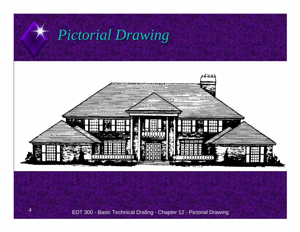
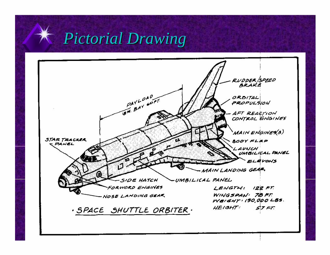
Examples of pictorial drawing use:Architects
Use pictorial drawing to show what a finished building will look like.
Ad agenciesUse pictorial drawing to display new products.
4 EDT 300 - Basic Technical Drafing - Chapter 12 - Pictorial Drawing
Pictorial DrawingPictorial Drawing
5 EDT 300 - Basic Technical Drafing - Chapter 12 - Pictorial Drawing
Pictorial DrawingPictorial Drawing
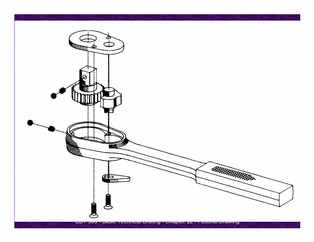
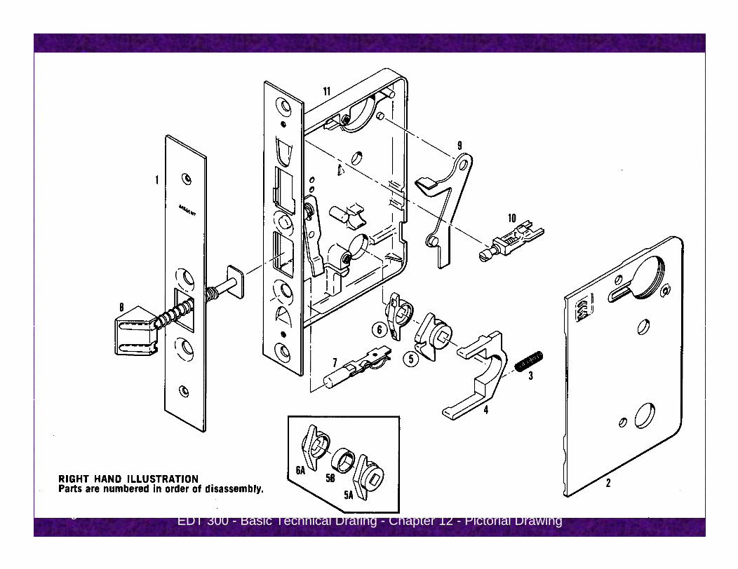
Pictorial drawing is often used in exploded drawings on production and assembly drawings.
Refer to Figure 12-1
6 EDT 300 - Basic Technical Drafing - Chapter 12 - Pictorial Drawing
7 EDT 300 - Basic Technical Drafing - Chapter 12 - Pictorial Drawing
Pictorial DrawingPictorial Drawing
Views are made to illustrate the operation of machines, and equipment.
Pictorial sketches are used to help convey ideas that are hard to describe in words.
8 EDT 300 - Basic Technical Drafing - Chapter 12 - Pictorial Drawing
Pictorial DrawingPictorial Drawing
9 EDT 300 - Basic Technical Drafing - Chapter 12 - Pictorial Drawing
10 EDT 300 - Basic Technical Drafing - Chapter 12 - Pictorial Drawing
Pictorial DrawingPictorial Drawing
Pictorial drawing can be Perspective Views
Show object as it actually looks to the eye.Most difficult to draw
Isometric ViewsEasier to draw than perspective.Do not look as good as perspective.
Oblique ViewsEasier to draw than perspective.Do not look as good as perspective or isometric.Is a front view with a depth.
EDT 300 - Basic Technical Drafing - Chapter 12 - Pictorial Drawing 11
Isometric DrawingIsometric Drawing
12 EDT 300 - Basic Technical Drafing - Chapter 12 - Pictorial Drawing
Isometric DrawingIsometric Drawing
Pictorial drawings, in general, are made to show how something looks.
Since hidden lines are not part of the picture they are normally left out and are not drawn in isometric drawings.
13 EDT 300 - Basic Technical Drafing - Chapter 12 - Pictorial Drawing
Isometric DrawingIsometric Drawing
Isometric drawing is Similar to isometric sketching except that it is created using instruments.
14 EDT 300 - Basic Technical Drafing - Chapter 12 - Pictorial Drawing
Isometric DrawingIsometric Drawing
Objects are aligned with three isometric axesat 120o angles to each other.
XYZ
Oriented 120 degrees apart from each other.
Refer to Figure 12.4.
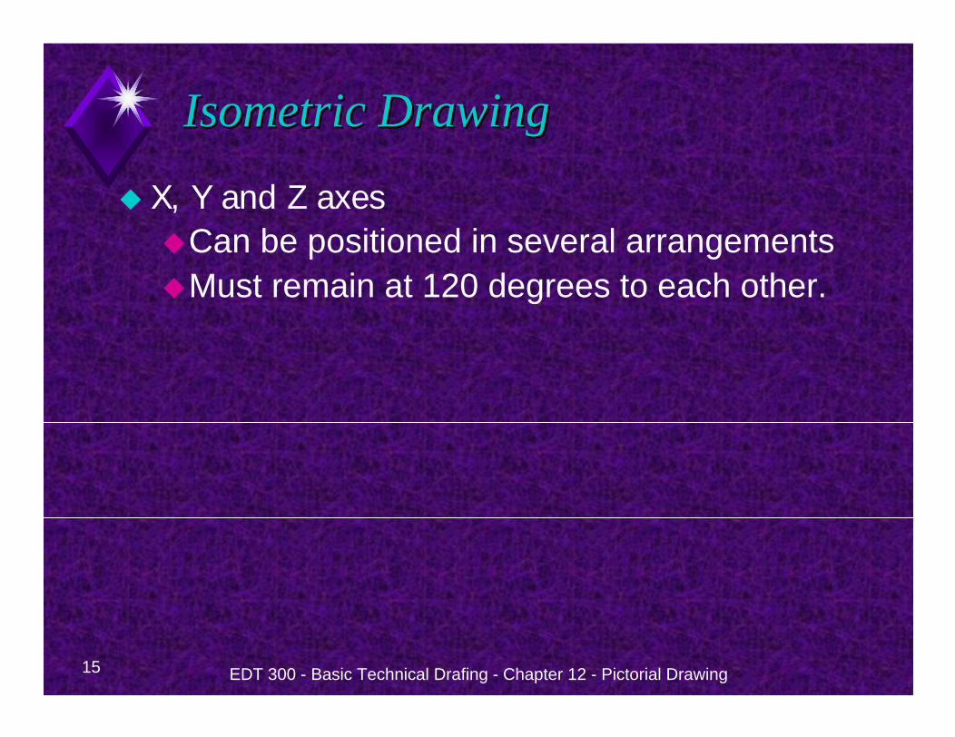
15 EDT 300 - Basic Technical Drafing - Chapter 12 - Pictorial Drawing
Isometric DrawingIsometric Drawing
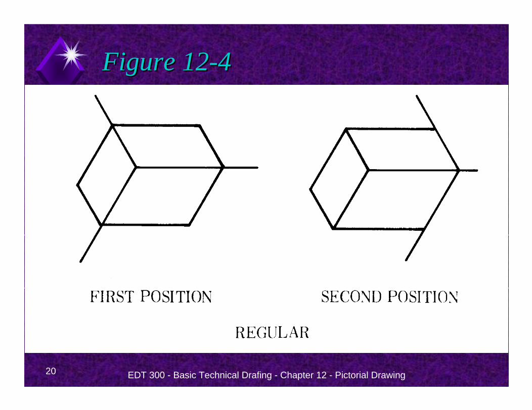
X, Y and Z axes Can be positioned in several arrangementsMust remain at 120 degrees to each other.
16 EDT 300 - Basic Technical Drafing - Chapter 12 - Pictorial Drawing
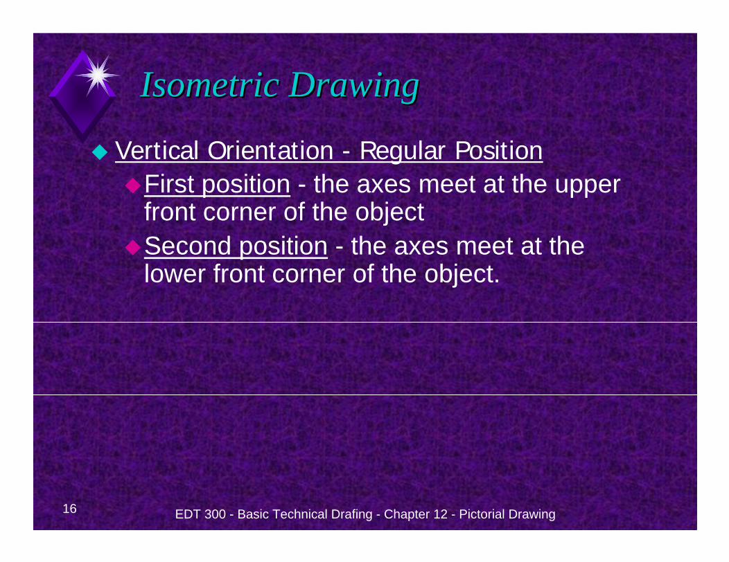
Isometric DrawingIsometric Drawing
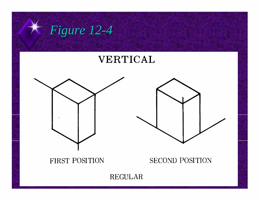
Vertical Orientation - Regular PositionFirst position - the axes meet at the upper front corner of the objectSecond position - the axes meet at the lower front corner of the object.
17 EDT 300 - Basic Technical Drafing - Chapter 12 - Pictorial Drawing
Figure 12Figure 12--44
18 EDT 300 - Basic Technical Drafing - Chapter 12 - Pictorial Drawing
Figure 12Figure 12--44
19 EDT 300 - Basic Technical Drafing - Chapter 12 - Pictorial Drawing
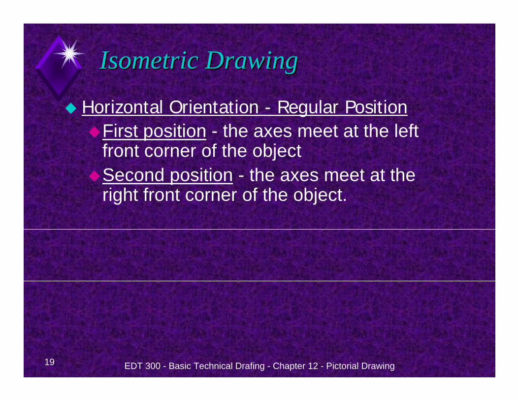
Isometric DrawingIsometric Drawing
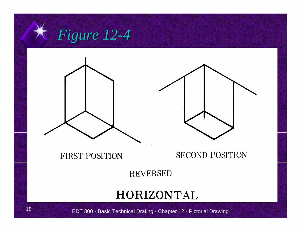
Horizontal Orientation - Regular PositionFirst position - the axes meet at the left front corner of the objectSecond position - the axes meet at the right front corner of the object.
20 EDT 300 - Basic Technical Drafing - Chapter 12 - Pictorial Drawing
Figure 12Figure 12--44
21 EDT 300 - Basic Technical Drafing - Chapter 12 - Pictorial Drawing
Figure 12Figure 12--44
EDT 300 - Basic Technical Drafing - Chapter 12 - Pictorial Drawing 22
Isometric LinesIsometric Lines
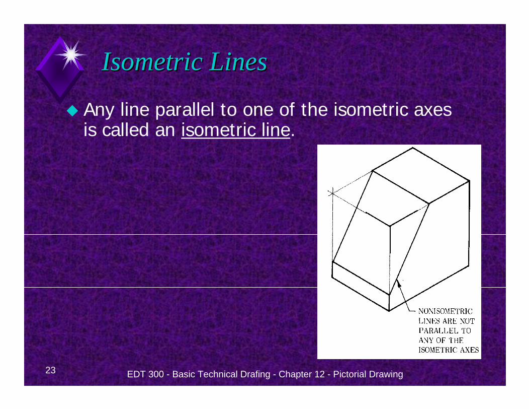
23 EDT 300 - Basic Technical Drafing - Chapter 12 - Pictorial Drawing
Isometric LinesIsometric Lines
Any line parallel to one of the isometric axes is called an isometric line.
24 EDT 300 - Basic Technical Drafing - Chapter 12 - Pictorial Drawing
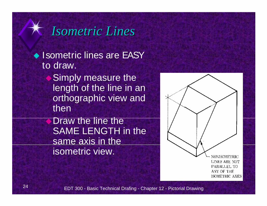
Isometric LinesIsometric Lines
Isometric lines are EASY to draw.
Simply measure the length of the line in an orthographic view and thenDraw the line the SAME LENGTH in the same axis in the isometric view.
EDT 300 - Basic Technical Drafing - Chapter 12 - Pictorial Drawing 25
NonNon--isometric Linesisometric Lines
26 EDT 300 - Basic Technical Drafing - Chapter 12 - Pictorial Drawing
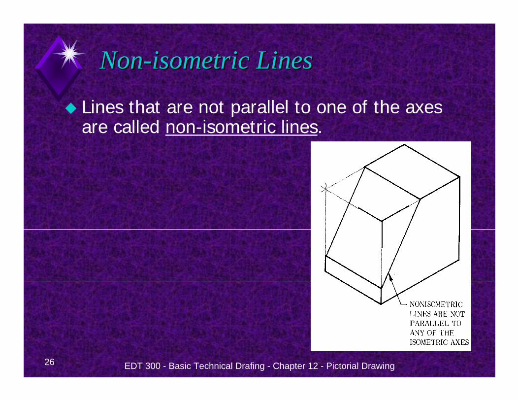
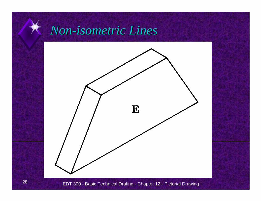
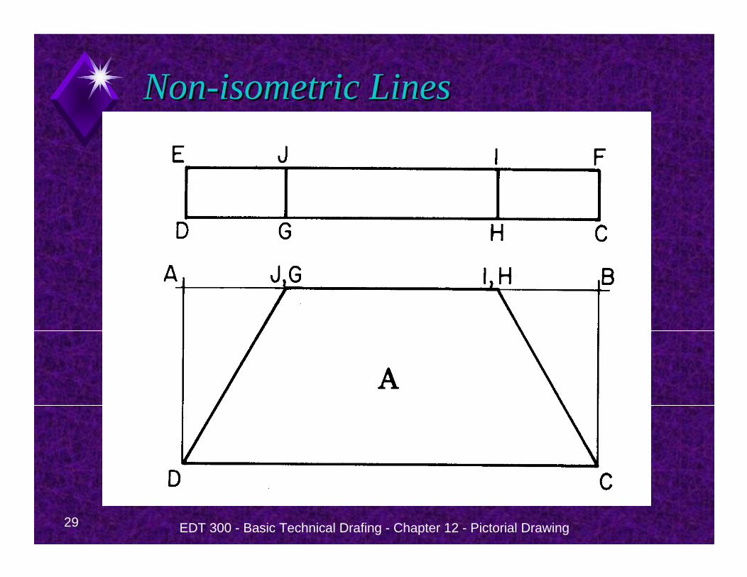
NonNon--isometric Linesisometric Lines
Lines that are not parallel to one of the axes are called non-isometric lines.
27 EDT 300 - Basic Technical Drafing - Chapter 12 - Pictorial Drawing
NonNon--isometric Linesisometric Lines
Measurements can be made only on isometric lines.
Non-isometric lines do not show in their true length so they cannot be measured.
28 EDT 300 - Basic Technical Drafing - Chapter 12 - Pictorial Drawing
NonNon--isometric Linesisometric Lines
29 EDT 300 - Basic Technical Drafing - Chapter 12 - Pictorial Drawing
NonNon--isometric Linesisometric Lines
30 EDT 300 - Basic Technical Drafing - Chapter 12 - Pictorial Drawing
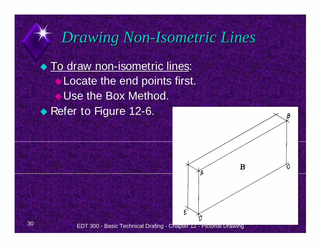
Drawing NonDrawing Non--Isometric LinesIsometric Lines
To draw non-isometric lines:Locate the end points first.Use the Box Method.
Refer to Figure 12-6.
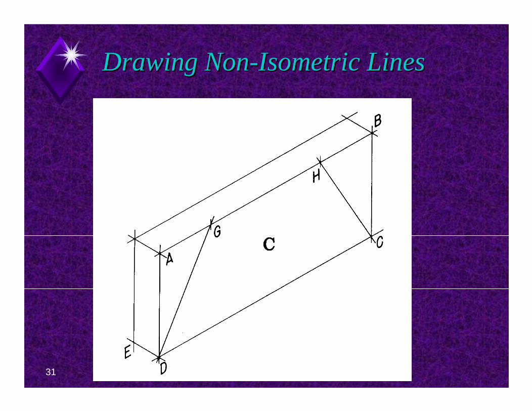
31 EDT 300 - Basic Technical Drafing - Chapter 12 - Pictorial Drawing
Drawing NonDrawing Non--Isometric LinesIsometric Lines
32 EDT 300 - Basic Technical Drafing - Chapter 12 - Pictorial Drawing
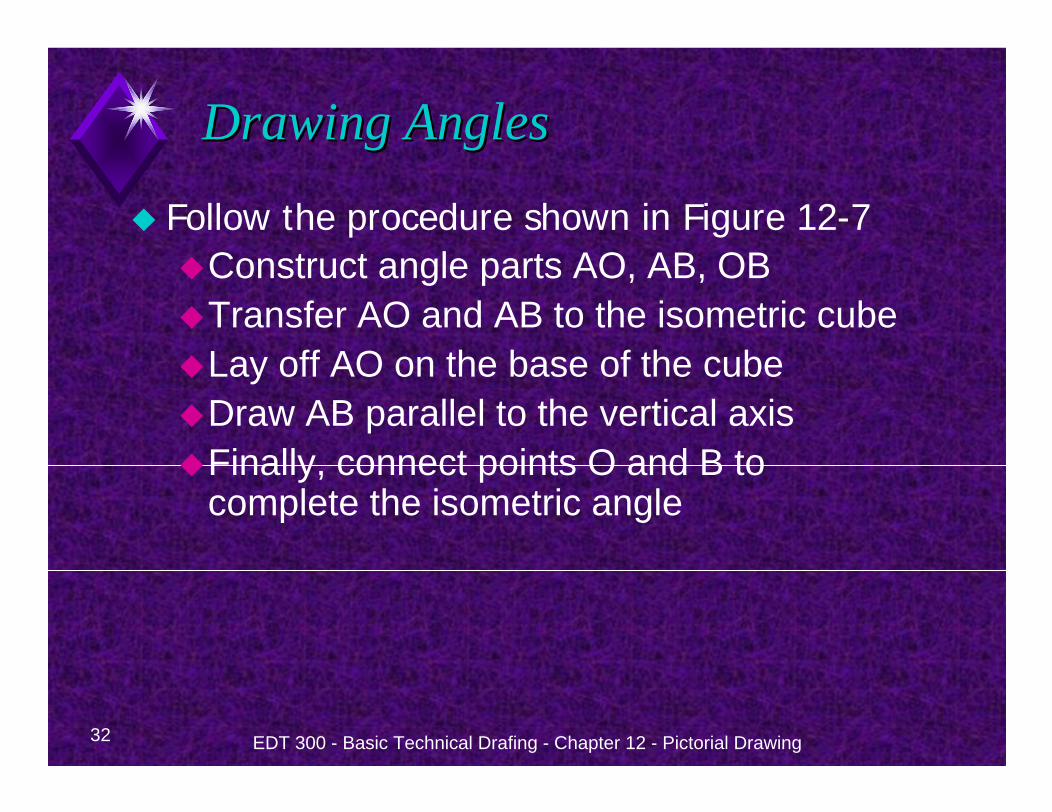
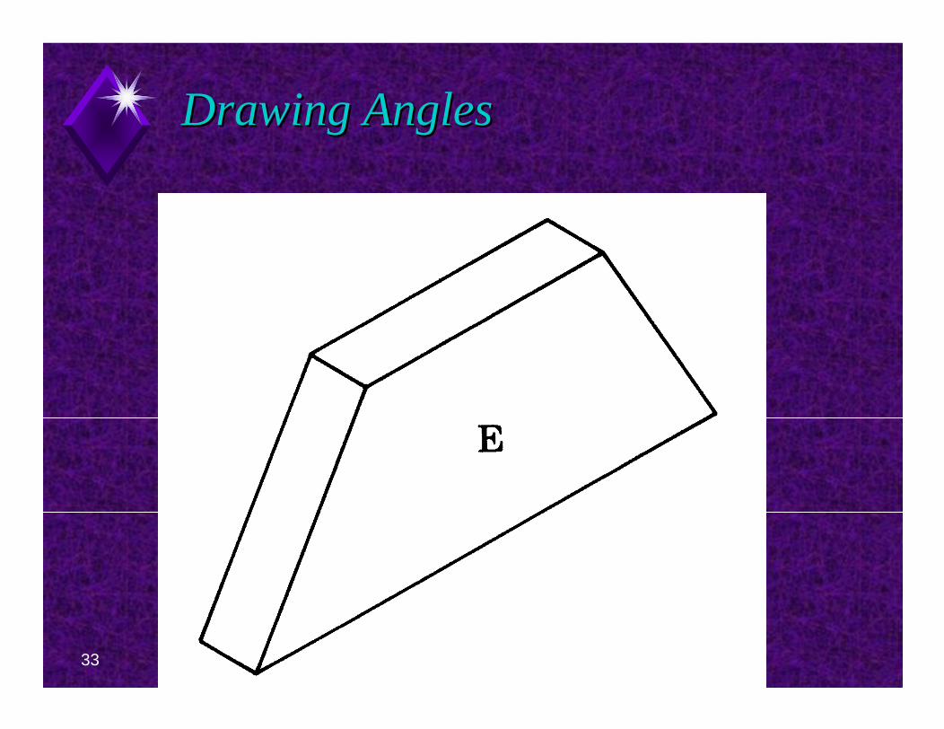
Drawing AnglesDrawing Angles
Follow the procedure shown in Figure 12-7Construct angle parts AO, AB, OBTransfer AO and AB to the isometric cubeLay off AO on the base of the cubeDraw AB parallel to the vertical axisFinally, connect points O and B to complete the isometric angle
33 EDT 300 - Basic Technical Drafing - Chapter 12 - Pictorial Drawing
Drawing AnglesDrawing Angles
EDT 300 - Basic Technical Drafing - Chapter 12 - Pictorial Drawing 34
Isometric CirclesIsometric Circles
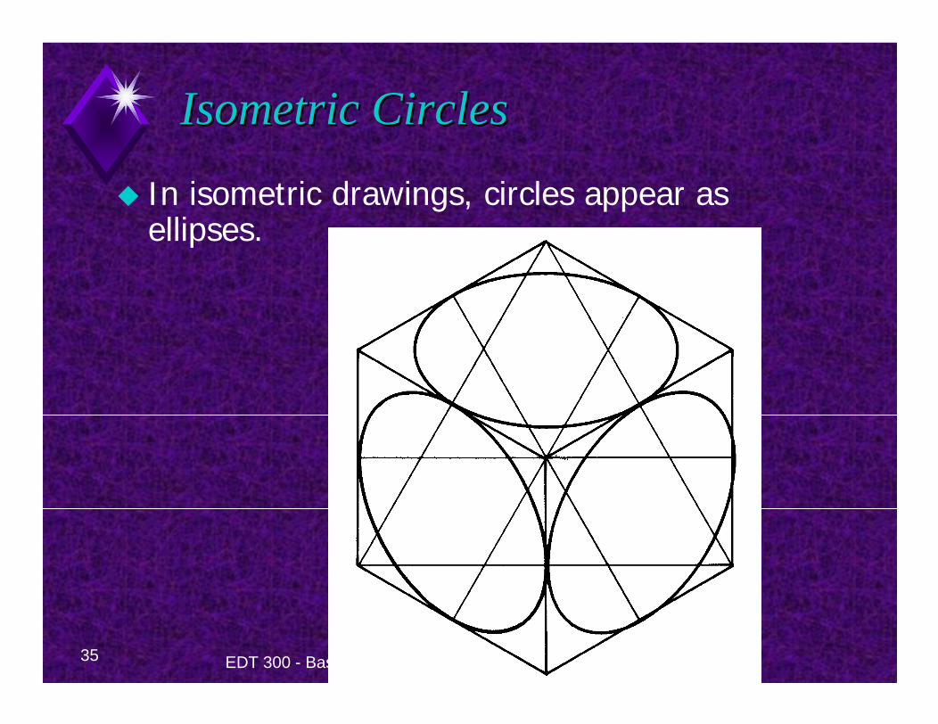
35 EDT 300 - Basic Technical Drafing - Chapter 12 - Pictorial Drawing
Isometric CirclesIsometric Circles
In isometric drawings, circles appear as ellipses.
36 EDT 300 - Basic Technical Drafing - Chapter 12 - Pictorial Drawing
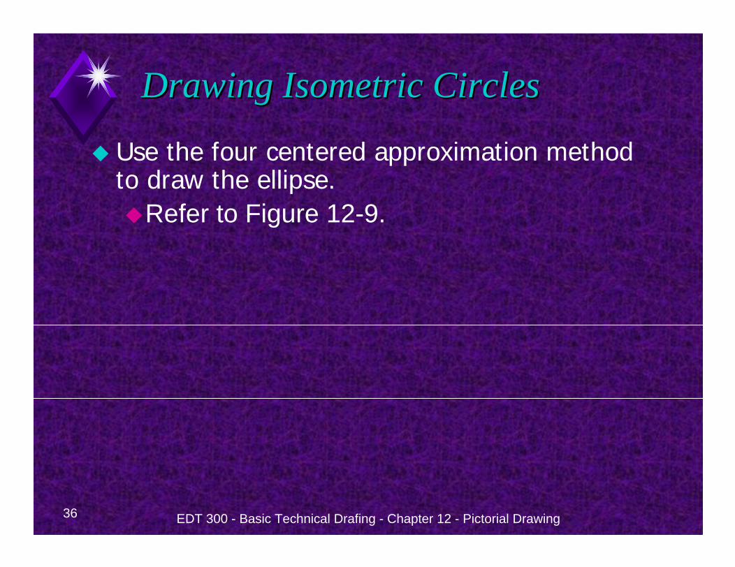
Drawing Isometric CirclesDrawing Isometric Circles
Use the four centered approximation method to draw the ellipse.
Refer to Figure 12-9.
37 EDT 300 - Basic Technical Drafing - Chapter 12 - Pictorial Drawing
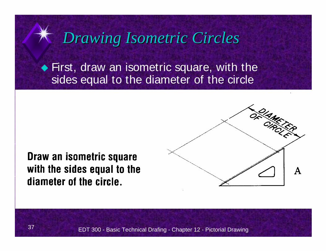
Drawing Isometric CirclesDrawing Isometric Circles
First, draw an isometric square, with the sides equal to the diameter of the circle
38 EDT 300 - Basic Technical Drafing - Chapter 12 - Pictorial Drawing
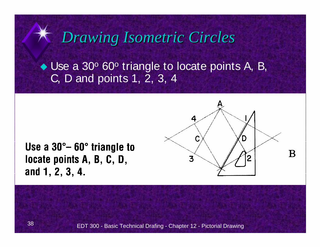
Drawing Isometric CirclesDrawing Isometric Circles
Use a 30o 60o triangle to locate points A, B, C, D and points 1, 2, 3, 4
39 EDT 300 - Basic Technical Drafing - Chapter 12 - Pictorial Drawing
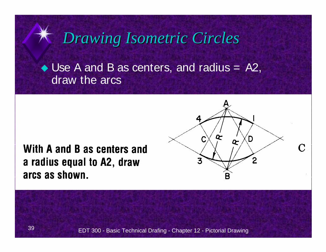
Drawing Isometric CirclesDrawing Isometric Circles
Use A and B as centers, and radius = A2, draw the arcs
40 EDT 300 - Basic Technical Drafing - Chapter 12 - Pictorial Drawing
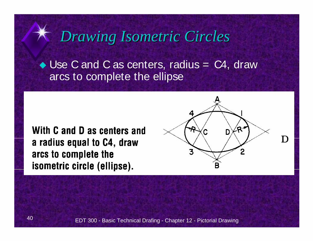
Drawing Isometric CirclesDrawing Isometric Circles
Use C and C as centers, radius = C4, draw arcs to complete the ellipse

41 EDT 300 - Basic Technical Drafing - Chapter 12 - Pictorial Drawing
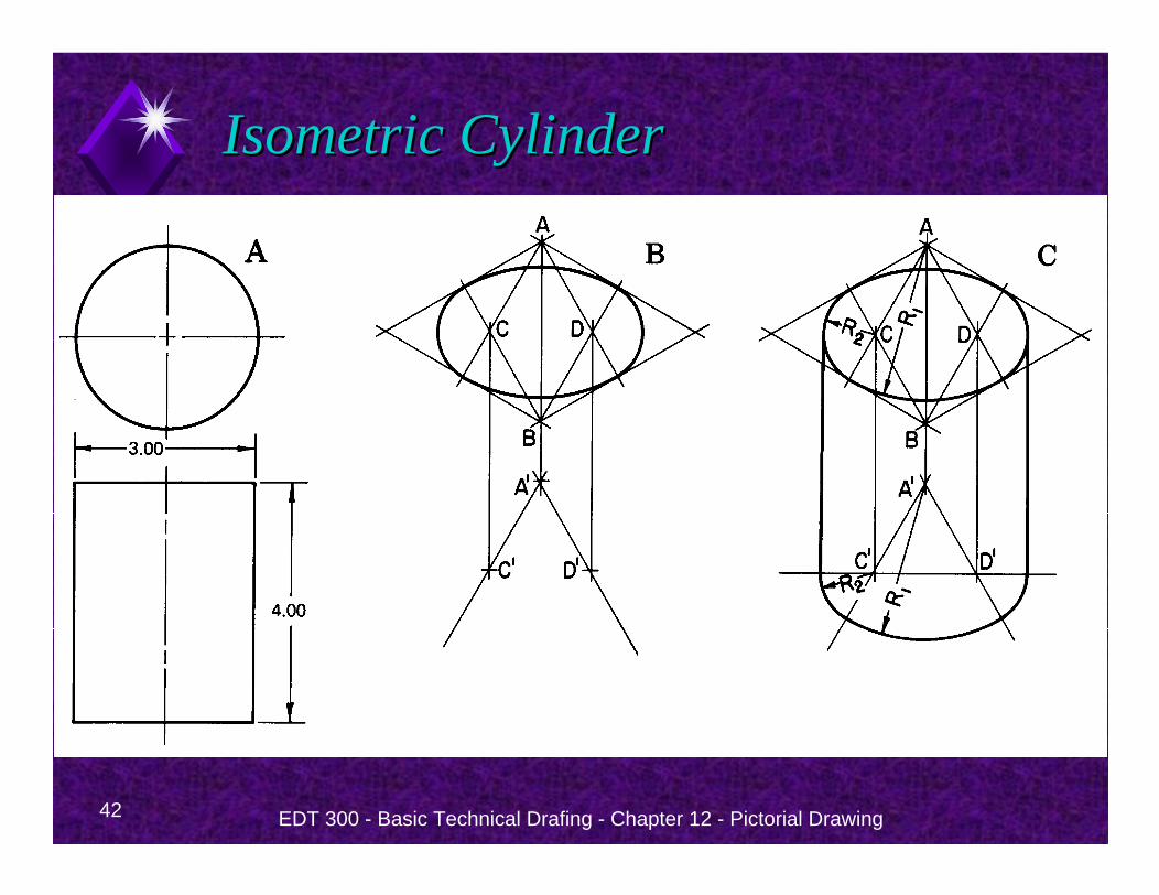
Isometric CylinderIsometric Cylinder
To draw an isometric cylinderUse Figure 12-9 to construct the top ellipse.Drop centers at a distance equal to the height of the cylinder.Draw three arcs using the same radii as the ellipse at the top.Notice that the radii for the arcs at the bottom match those at the top.
42 EDT 300 - Basic Technical Drafing - Chapter 12 - Pictorial Drawing
Isometric CylinderIsometric Cylinder
43 EDT 300 - Basic Technical Drafing - Chapter 12 - Pictorial Drawing
Isometric Quarter RoundsIsometric Quarter Rounds
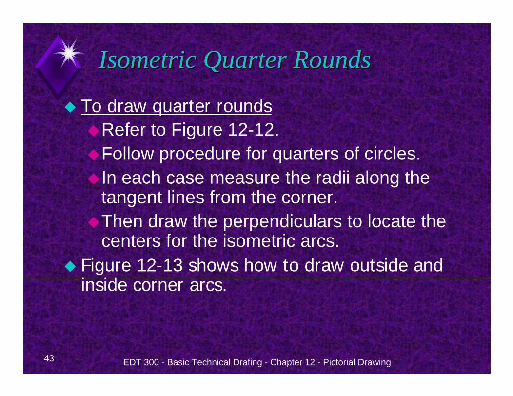
To draw quarter roundsRefer to Figure 12-12.Follow procedure for quarters of circles.In each case measure the radii along the tangent lines from the corner.Then draw the perpendiculars to locate the centers for the isometric arcs.
Figure 12-13 shows how to draw outside and inside corner arcs.
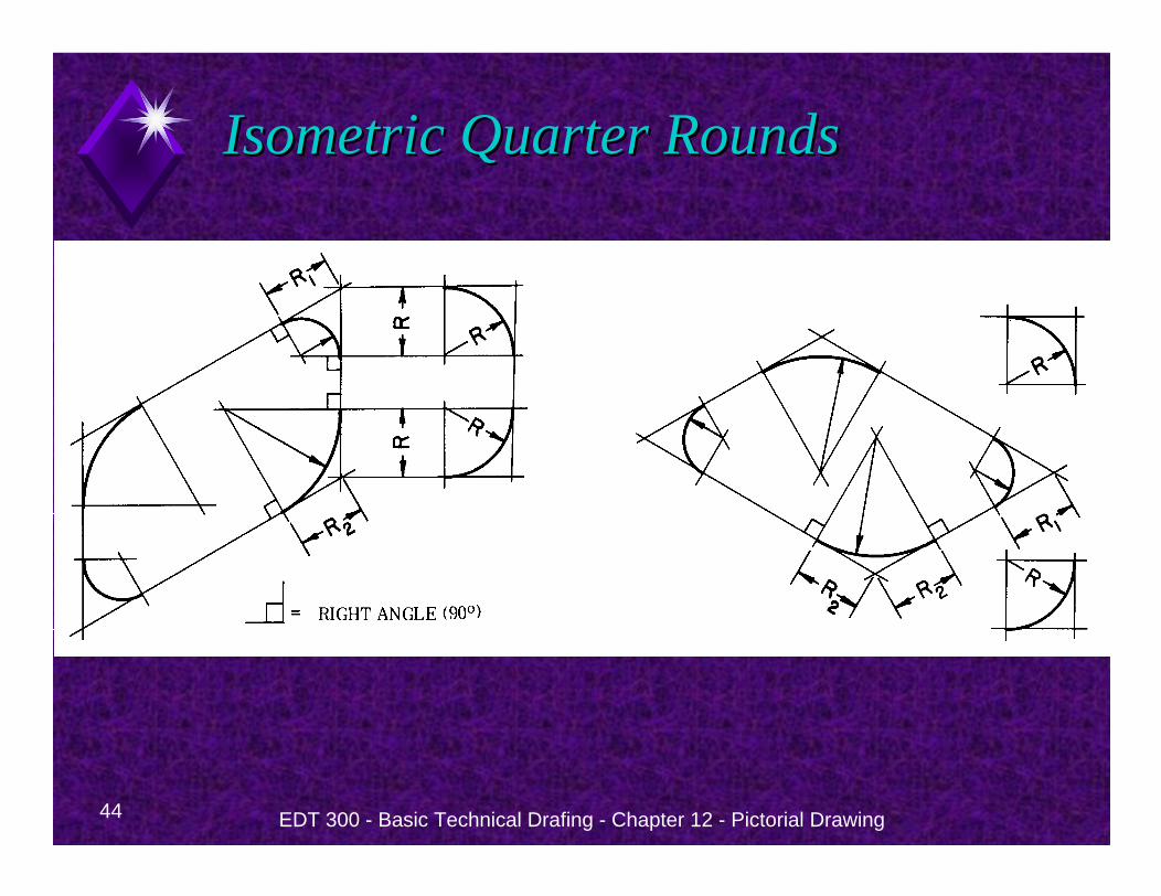
44 EDT 300 - Basic Technical Drafing - Chapter 12 - Pictorial Drawing
Isometric Quarter RoundsIsometric Quarter Rounds

EDT 300 - Basic Technical Drafing - Chapter 12 - Pictorial Drawing 45
Isometric TemplatesIsometric Templates
46 EDT 300 - Basic Technical Drafing - Chapter 12 - Pictorial Drawing
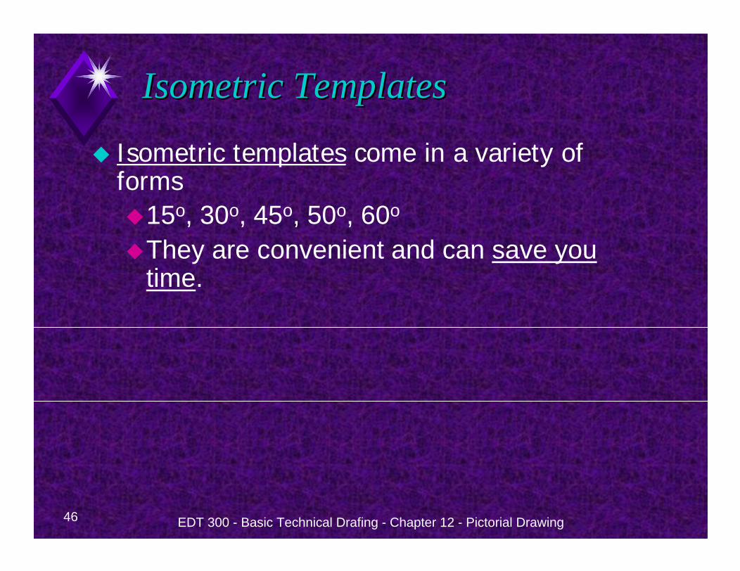
Isometric TemplatesIsometric Templates
Isometric templates come in a variety of forms
15o, 30o, 45o, 50o, 60o
They are convenient and can save you time.
EDT 300 - Basic Technical Drafing - Chapter 12 - Pictorial Drawing 47
Creating an Isometric DrawingCreating an Isometric Drawing
48 EDT 300 - Basic Technical Drafing - Chapter 12 - Pictorial Drawing
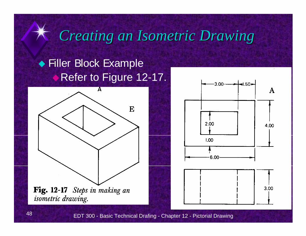
Creating an Isometric DrawingCreating an Isometric Drawing
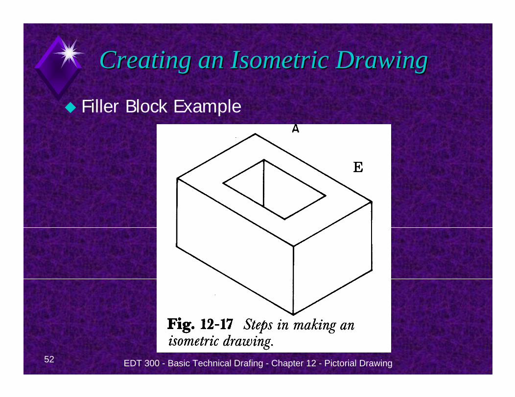
Filler Block ExampleRefer to Figure 12-17.
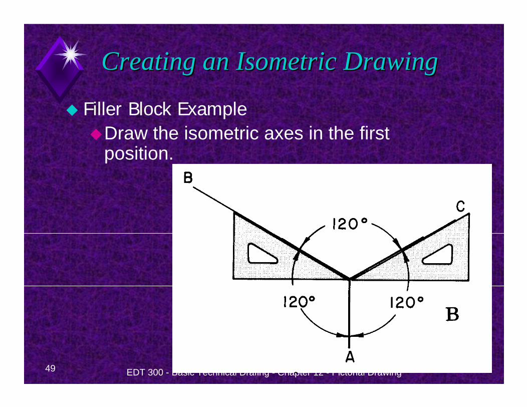
49 EDT 300 - Basic Technical Drafing - Chapter 12 - Pictorial Drawing
Creating an Isometric DrawingCreating an Isometric Drawing
Filler Block ExampleDraw the isometric axes in the first position.
50 EDT 300 - Basic Technical Drafing - Chapter 12 - Pictorial Drawing
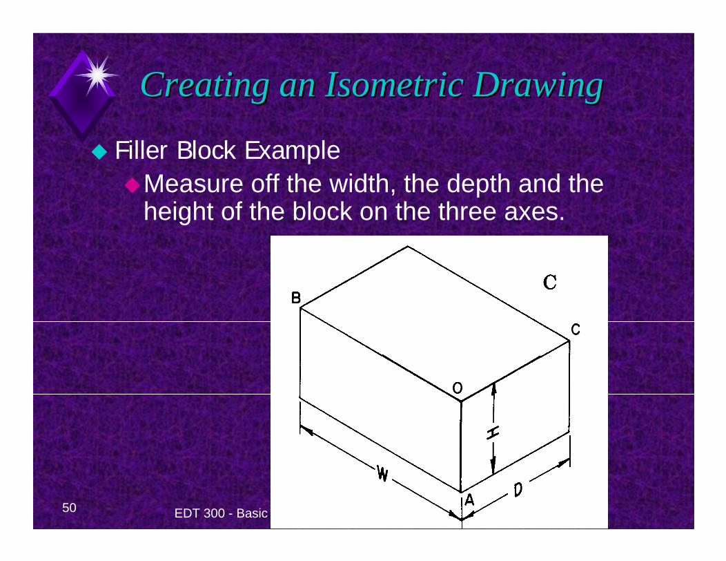
Creating an Isometric DrawingCreating an Isometric Drawing
Filler Block ExampleMeasure off the width, the depth and the height of the block on the three axes.
51 EDT 300 - Basic Technical Drafing - Chapter 12 - Pictorial Drawing
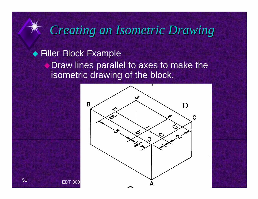
Creating an Isometric DrawingCreating an Isometric Drawing
Filler Block ExampleDraw lines parallel to axes to make the isometric drawing of the block.
52 EDT 300 - Basic Technical Drafing - Chapter 12 - Pictorial Drawing
Creating an Isometric DrawingCreating an Isometric Drawing
Filler Block Example
53 EDT 300 - Basic Technical Drafing - Chapter 12 - Pictorial Drawing
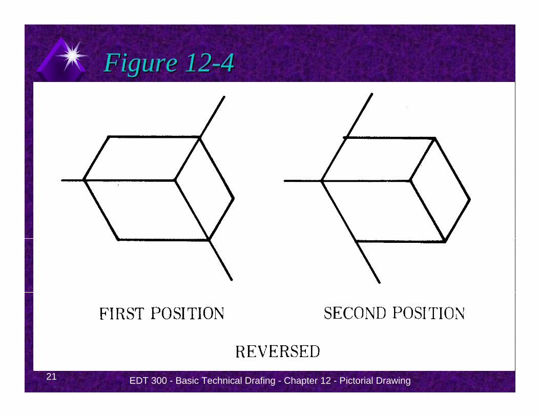
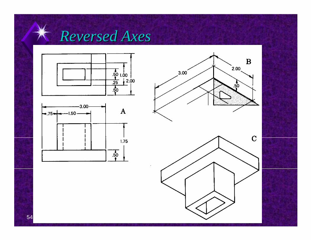
Reversed AxesReversed Axes
To draw an object as if viewed from below, reverse the position of the axes.
Follow example in Figure 12-20.
54 EDT 300 - Basic Technical Drafing - Chapter 12 - Pictorial Drawing
Reversed AxesReversed Axes
55 EDT 300 - Basic Technical Drafing - Chapter 12 - Pictorial Drawing
Creating an Isometric DrawingCreating an Isometric Drawing
When long pieces are drawn in isometric, make the long axis horizontal.
Refer to Figure 12-21
EDT 300 - Basic Technical Drafing - Chapter 12 - Pictorial Drawing 56
Dimensioning Isometric DrawingsDimensioning Isometric Drawings
57 EDT 300 - Basic Technical Drafing - Chapter 12 - Pictorial Drawing
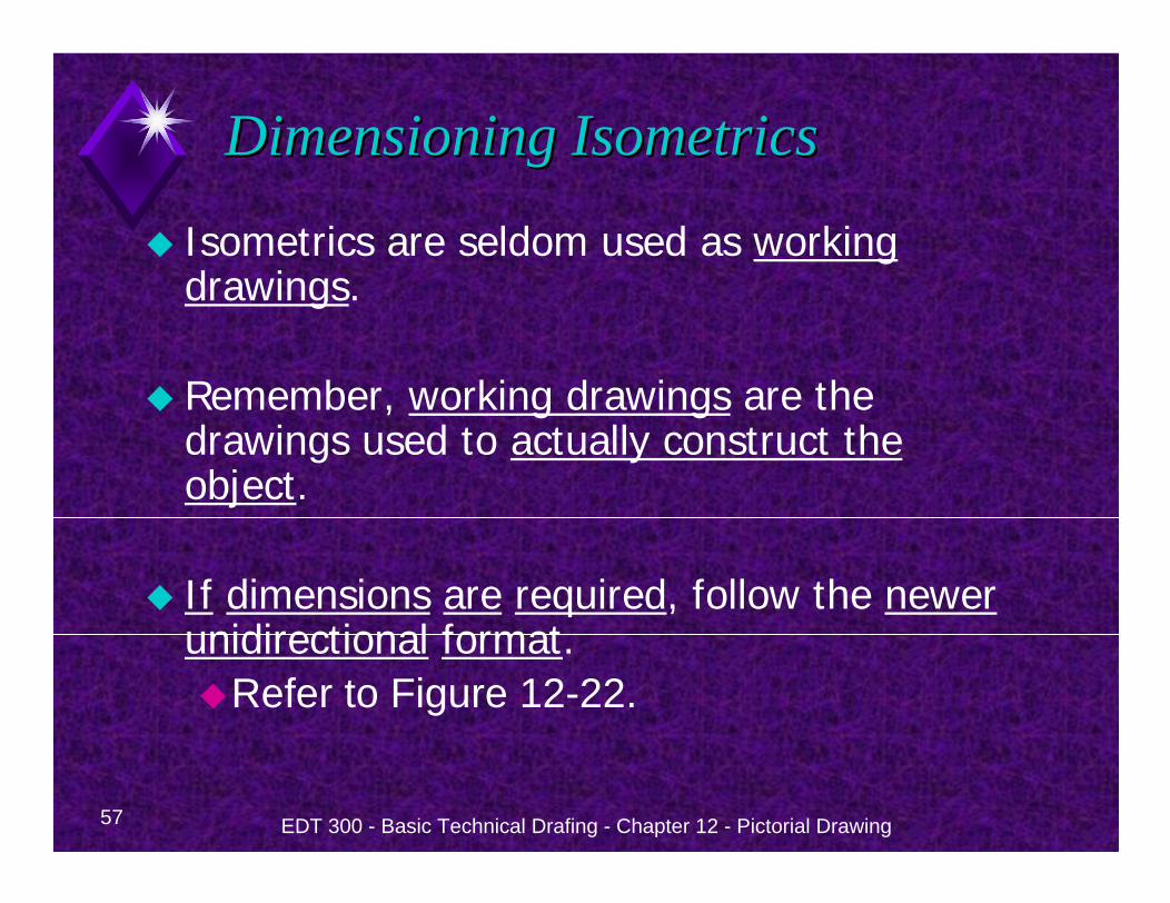
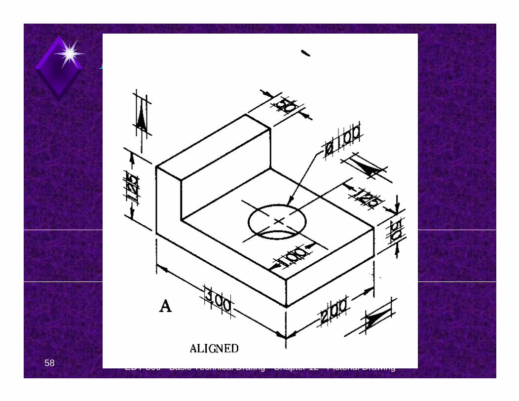
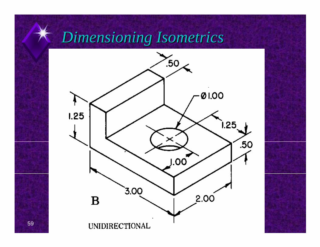
Dimensioning IsometricsDimensioning Isometrics
Isometrics are seldom used as working drawings.
Remember, working drawings are the drawings used to actually construct the object.
I f dimensions are required, follow the newerunidirectional format.
Refer to Figure 12-22.
58 EDT 300 - Basic Technical Drafing - Chapter 12 - Pictorial Drawing
Dimensioning IsometricsDimensioning Isometrics
59 EDT 300 - Basic Technical Drafing - Chapter 12 - Pictorial Drawing
Dimensioning IsometricsDimensioning Isometrics
EDT 300 - Basic Technical Drafing - Chapter 12 - Pictorial Drawing 60
Isometrics Isometrics Multiple ScalesMultiple Scales
61 EDT 300 - Basic Technical Drafing - Chapter 12 - Pictorial Drawing
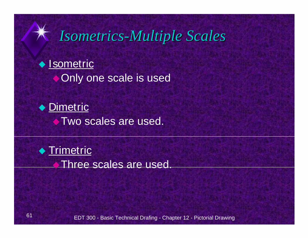
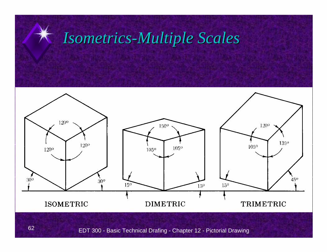
IsometricsIsometrics--Multiple ScalesMultiple Scales
IsometricOnly one scale is used
DimetricTwo scales are used.
TrimetricThree scales are used.
62 EDT 300 - Basic Technical Drafing - Chapter 12 - Pictorial Drawing
IsometricsIsometrics--Multiple ScalesMultiple Scales
EDT 300 - Basic Technical Drafing - Chapter 12 - Pictorial Drawing 63
Oblique DrawingsOblique Drawings
64 EDT 300 - Basic Technical Drafing - Chapter 12 - Pictorial Drawing
Oblique DrawingsOblique Drawings
Oblique drawings are Similar to isometric drawings, Are drawn on three axes (X, Y, Z).Two axes are parallel to the picture plane(the plane on which the view is drawn).These two axes always are at right angles.Think Front View with depth .
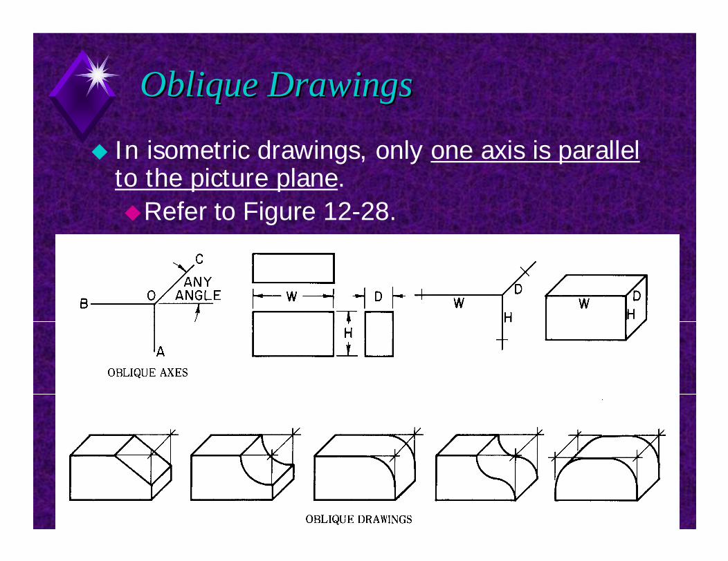
65 EDT 300 - Basic Technical Drafing - Chapter 12 - Pictorial Drawing
Oblique DrawingsOblique Drawings
In isometric drawings, only one axis is parallel to the picture plane.
Refer to Figure 12-28.
66 EDT 300 - Basic Technical Drafing - Chapter 12 - Pictorial Drawing
Oblique DrawingsOblique Drawings
Oblique drawings show an object as if viewed face on.The object is seen squarely with no distortion.
67 EDT 300 - Basic Technical Drafing - Chapter 12 - Pictorial Drawing
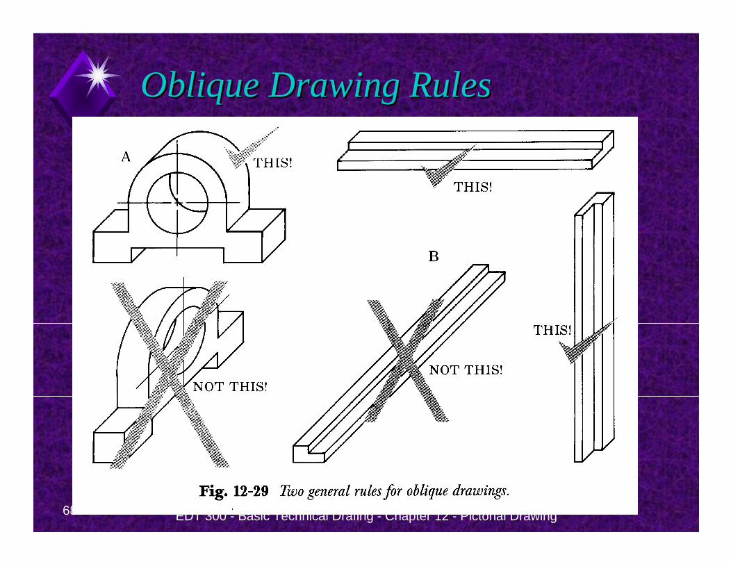
Oblique Drawing RulesOblique Drawing Rules
To create an oblique drawing:Draw a front view, long side horizontalDraw the depthRefer to Figure 12-29.
68 EDT 300 - Basic Technical Drafing - Chapter 12 - Pictorial Drawing
Oblique Drawing RulesOblique Drawing Rules
69 EDT 300 - Basic Technical Drafing - Chapter 12 - Pictorial Drawing
Oblique ProjectionOblique Projection
Oblique projection is a way of showing depth.
Depth is shown by projector lines.
Projector lines represent receding edges of an object.
These lines are drawn at an angle other than 90o from the picture plane so they will be visible in the front view.
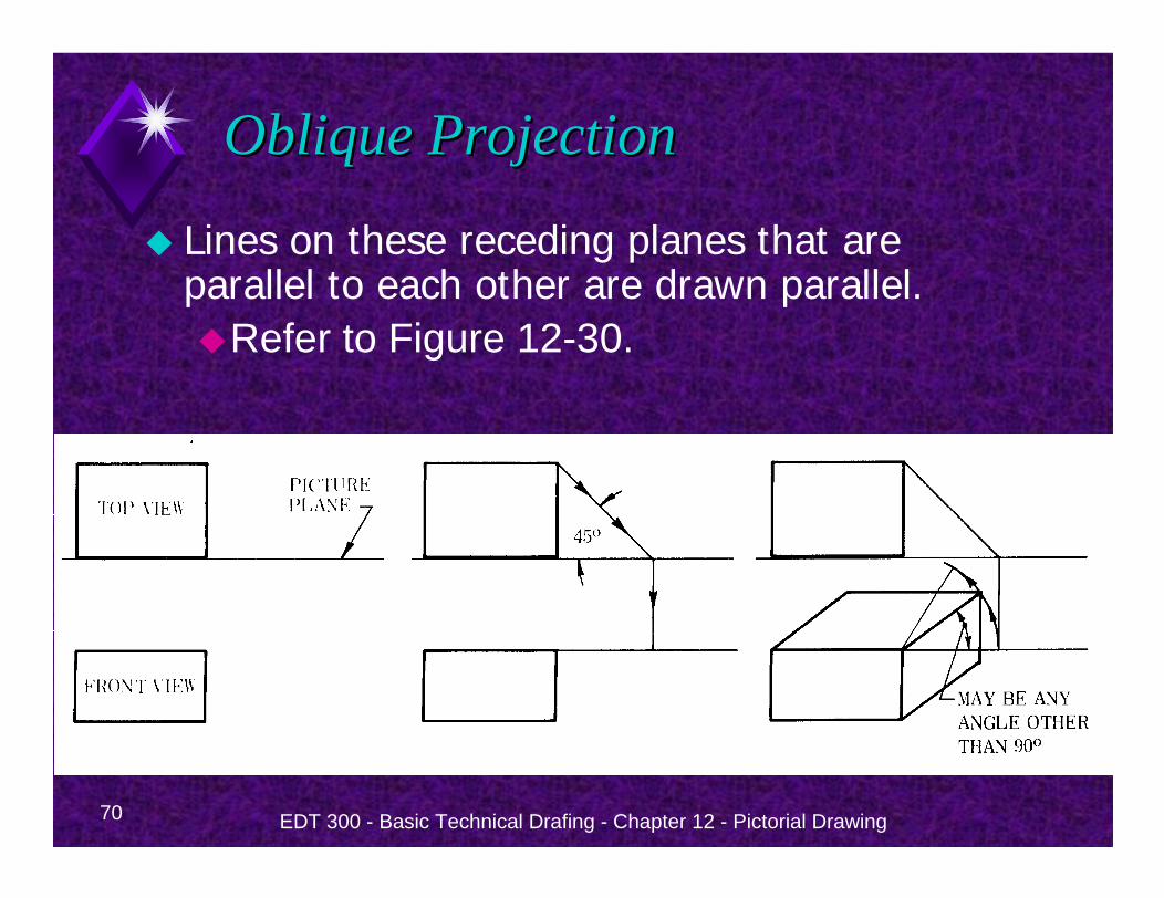
70 EDT 300 - Basic Technical Drafing - Chapter 12 - Pictorial Drawing
Oblique ProjectionOblique Projection
Lines on these receding planes that are parallel to each other are drawn parallel.
Refer to Figure 12-30.
71 EDT 300 - Basic Technical Drafing - Chapter 12 - Pictorial Drawing
Oblique ProjectionOblique Projection
Because oblique drawing can show one face of an object without distortion it has a distinct advantage over isometric.
Oblique drawings are useful for showing objects with irregular outlines.
72 EDT 300 - Basic Technical Drafing - Chapter 12 - Pictorial Drawing
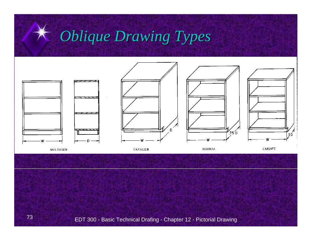
Oblique Drawing TypesOblique Drawing Types
Cavalier Obliquereceding lines are drawn full length.
Normal Oblique.receding lines are drawn 3/4 length.
Cabinet Oblique.receding lines are drawn 1/2 lengthnamed this way because it is often used in the furniture industry
Refer to Figure 12-32
73 EDT 300 - Basic Technical Drafing - Chapter 12 - Pictorial Drawing
Oblique Drawing TypesOblique Drawing Types
74 EDT 300 - Basic Technical Drafing - Chapter 12 - Pictorial Drawing
Oblique ConstructionsOblique Constructions
Angles and Inclined SurfacesAngles that are parallel to the picture planeare shown full size.For all other angles, lay the angle off by locating both ends of the slanting line.Remember to lay off angles by measurements parallel to one of the axes.
75 EDT 300 - Basic Technical Drafing - Chapter 12 - Pictorial Drawing
Oblique ConstructionsOblique Constructions
Oblique CirclesUse the four-center method for ellipses.Ellipse templates give better results.If you use a template, block the oblique circle as an oblique square.
EDT 300 - Basic Technical Drafing - Chapter 12 - Pictorial Drawing 76
Perspective DrawingsPerspective Drawings
77 EDT 300 - Basic Technical Drafing - Chapter 12 - Pictorial Drawing
Perspective DrawingsPerspective Drawings
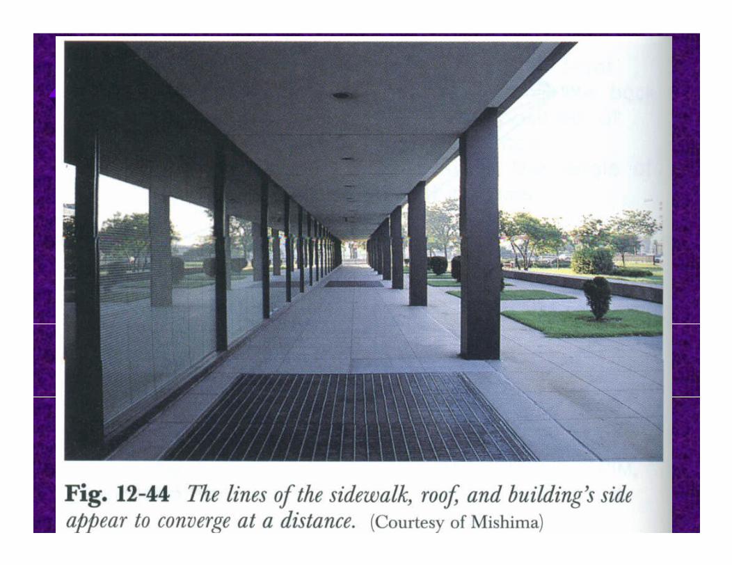
A perspective drawinga three-dimensional representation of an object as it looks to the eye from a particular point.look the most like photographs of all pictorial drawings.lines on the receding planes that are actually parallel are not drawn parallel.These lines are drawn as if they were converging.
78 EDT 300 - Basic Technical Drafing - Chapter 12 - Pictorial Drawing
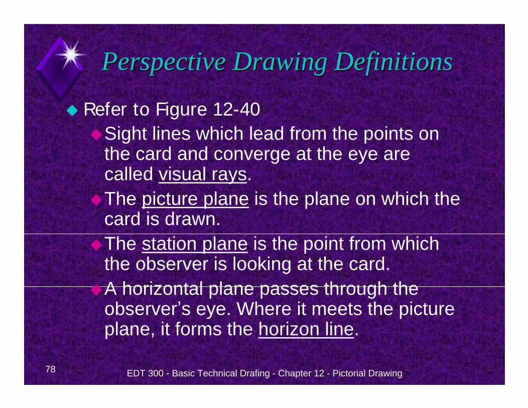
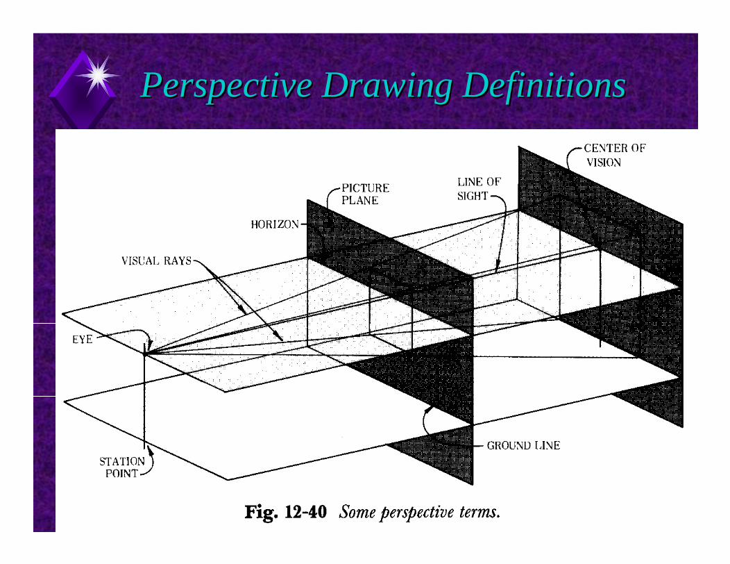
Perspective Drawing DefinitionsPerspective Drawing Definitions
Refer to Figure 12-40Sight lines which lead from the points on the card and converge at the eye are called visual rays.The picture plane is the plane on which the card is drawn.The station plane is the point from which the observer is looking at the card.A horizontal plane passes through the observer s eye. Where it meets the picture plane, it forms the horizon line.
79 EDT 300 - Basic Technical Drafing - Chapter 12 - Pictorial Drawing
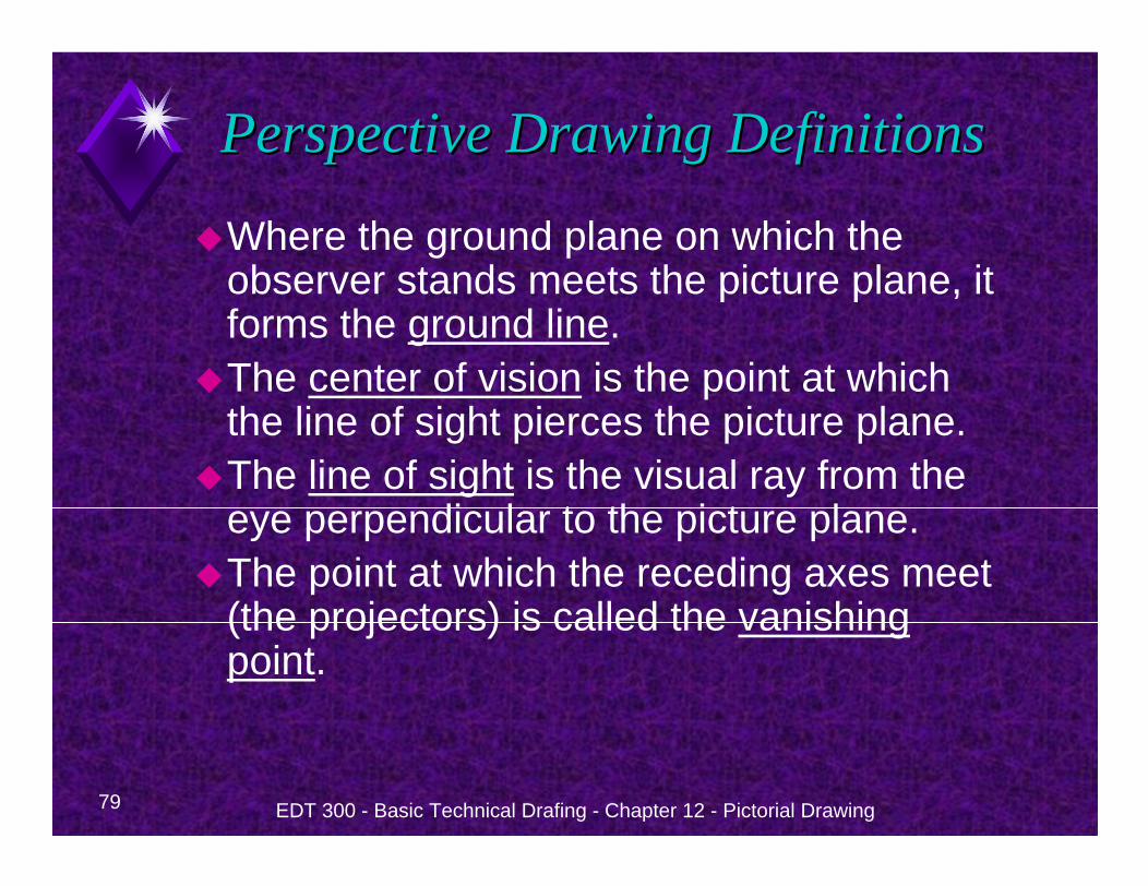
Perspective Drawing DefinitionsPerspective Drawing Definitions
Where the ground plane on which the observer stands meets the picture plane, it forms the ground line.The center of vision is the point at which the line of sight pierces the picture plane.The line of sight is the visual ray from the eye perpendicular to the picture plane.The point at which the receding axes meet (the projectors) is called the vanishing point.
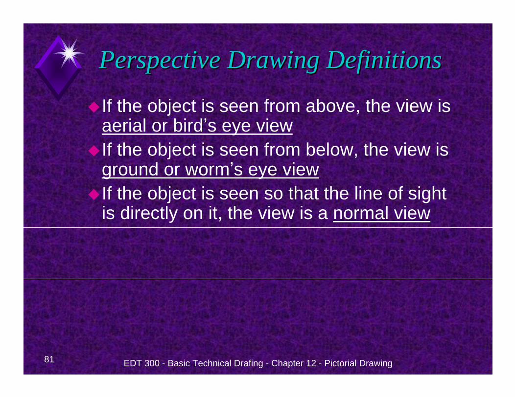
80 EDT 300 - Basic Technical Drafing - Chapter 12 - Pictorial Drawing
Perspective Drawing DefinitionsPerspective Drawing Definitions
81 EDT 300 - Basic Technical Drafing - Chapter 12 - Pictorial Drawing
Perspective Drawing DefinitionsPerspective Drawing Definitions
If the object is seen from above, the view is aerial or bird s eye viewIf the object is seen from below, the view is ground or worm s eye viewIf the object is seen so that the line of sight is directly on it, the view is a normal view
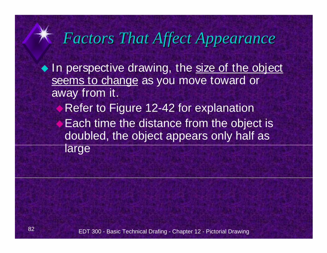
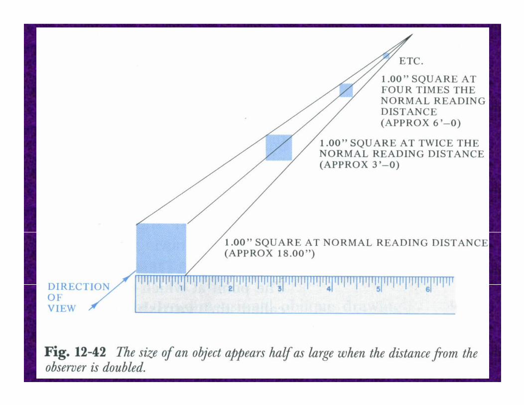
82 EDT 300 - Basic Technical Drafing - Chapter 12 - Pictorial Drawing
Factors That Affect AppearanceFactors That Affect Appearance
In perspective drawing, the size of the object seems to change as you move toward or away from it.
Refer to Figure 12-42 for explanationEach time the distance from the object is doubled, the object appears only half as large
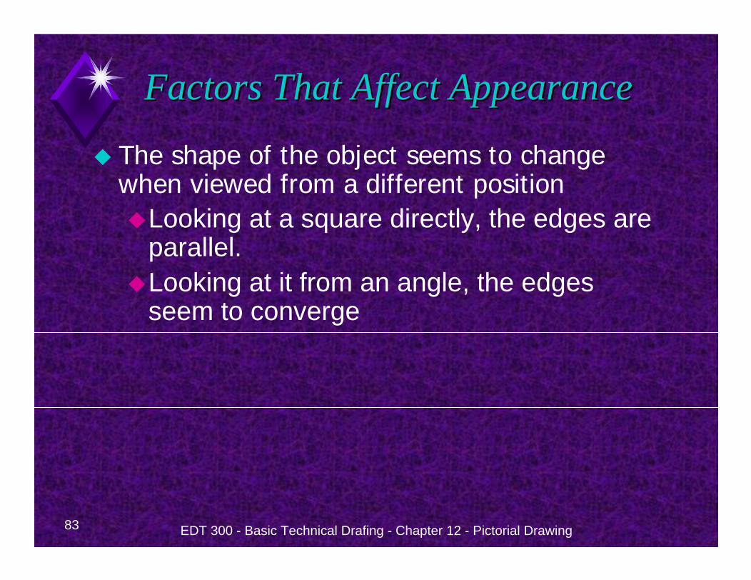
83 EDT 300 - Basic Technical Drafing - Chapter 12 - Pictorial Drawing
Factors That Affect AppearanceFactors That Affect Appearance
The shape of the object seems to change when viewed from a different position
Looking at a square directly, the edges are parallel. Looking at it from an angle, the edges seem to converge
84 EDT 300 - Basic Technical Drafing - Chapter 12 - Pictorial Drawing
85 EDT 300 - Basic Technical Drafing - Chapter 12 - Pictorial Drawing
One Point Perspective One Point Perspective
One-point perspective, has one vanishing pointalso called parallel perspective.
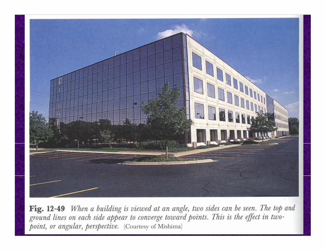
Two point perspective drawings have two vanishing points.
Also called angular perspective
86 EDT 300 - Basic Technical Drafing - Chapter 12 - Pictorial Drawing
87 EDT 300 - Basic Technical Drafing - Chapter 12 - Pictorial Drawing
88 EDT 300 - Basic Technical Drafing - Chapter 12 - Pictorial Drawing
89 EDT 300 - Basic Technical Drafing - Chapter 12 - Pictorial Drawing