Embed Size (px)
Citation preview

PHOTOSENSITIZERS FOR PHOTODYNAMIC ACTION AND
SYNTHESIS OF MODULES FOR A MOLECULAR
DEMULTIPLEXER
A THESIS
SUBMITTED TO DEPARTMENT OF CHEMISTRY
AND THE GRADUATE SCHOOL OF ENGINEERING AND SCIENCE
OF BILKENT UNIVERSITY
IN PARTIAL FULFILLMENT OF THE REQUIREMENTS
FOR THE DEGREE OF
MASTER OF SCIENCE
By
Tuğçe Durgut
August, 2014
I certify that I have read this thesis and that in my opinion it is fully adequate, in
scope and in quality, as a thesis of the degree of Master of Science.
………………………………….
Prof. Dr. Engin U. Akkaya (Advisor)
I certify that I have read this thesis and that in my opinion it is fully adequate, in
scope and in quality, as a thesis of the degree of Doctor of Philosophy.
………………………………….
Assoc. Prof. Dr. Dönüş Tuncel
I certify that I have read this thesis and that in my opinion it is fully adequate, in
scope and in quality, as a thesis of the degree of Doctor of Philosophy.
………………………………….
Assist. Prof. Dr. Murat Işık
Approved for the Graduate School of Engineering and Science:
………………………………….
Prof. Dr. Levent Onural
Director of the Graduate School

ABSTRACT
PHOTOSENSITIZERS FOR PHOTODYNAMIC ACTION AND SYNTHESIS OF
MODULES FOR A MOLECULAR DEMULTIPLEXER
Tuğçe Durgut
M.S. in Department of Chemistry
Supervisor: Prof. Dr. Engin Umut Akkaya
August, 2014
Photodynamic therapy (PDT) is a new therapeutic methodology that uses light as a
distinguishing tool for the treatment of diseased cells. In recent years PDT has
become one of the most preferred therapies because it is innocent for the healthy
cells and tissues while diagnosing and curing the malignant cells and tissues. Bodipy
is one of the most favorite fluorophore in this field due to its excellent chemical and
physical properties. Logic gates are widely used in modern technology as the
fundamentals of logical operations for the development of science. The progressive
advances leads to the emergence and growth of molecular logic gates. Molecular
logic gates can be used for the diagnosis and therapies of disease which are
originated from the heredity. In addition, they occupy an important place in the
theoretical and practical use of photodynamic therapy.
In the first part of my thesis, we designed and synthesized a calix[4]arene-Bodipy
conjugate molecule as a carrier for the photodynamic therapy agents. It is an
amphiphilic delivery molecule that is utilized for the curing of tumor tissues. In the
second part, we synthesized modules for molecular logic gate function, DEMUX
(demultiplexer), serving as a theranostic device which selects either singlet oxygen
channel or energy transfer between the modules depending on the inputs. The
superiority of the project is that it serves a realistic pathway for the PDT.
Keywords: Calixarenes, Logic gates, photodynamic therapy, demultiplexer
i
ÖZET
FOTODİNAMİK AKSİYON İÇİN FOTODUYARLAŞTIRICILAR VE
MOLEKÜLER DEMULTİPLEKSER MODÜLLERİNİN SENTEZİ
Tuğçe Durgut
Kimya Bölümü, Yüksek Lisans
Tez Yöneticisi: Prof. Dr. Engin Umut Akkaya
Ağustos, 2014
Fotodinamik terapi (PDT), ışığı hasta hücrelerin tedavisinde ayırt edici etken olarak
kullanan bir tanı ve tedavi yöntemidir. Kötücül hücre ve dokuların tanı ve tedavi
işlemleri süresince sağlıklı hücre ve dokulara zararsız olması sebebiyle son yıllarda
en çok tercih edilen terapi yöntemi fotodinamik terapi olmuştur. Bodipy, üstün
kimyasal ve fiziksel öellikleri sayesinde bu alandaki en gözde floroforlardan biridir.
Mantık işlemlerinin temelinde yatan mantık kapıları, bilimin ilerleyebilmesi için
modern teknolojide sıkça kullanılır. Bilimde ilerleyen gelişmeler moleküler mantık
kapılarının ortaya çıkıp gelişmesine öncülük etmiştir. Moleküler mantık kapıları
kalıtsal olan hastalıkların tanı ve tedavisinde kullanılabilir. Ayrıca, fotodinamik
terapinin teoritiksel ve pratik kullanmında önemli bir etki alanına sahiplerdir.
Tezimde, ilk bölümde fotodinamik terapi ajanslarını taşıyacak olan kaliks[4]aren-
bodipy türevini ve sentezledik. Bu molekül, ampifilik özellik göstermekte ve tümörlü
dokular için çalışmaktadır. Ikinci bölümde ise, bir moleküler mantık kapısı olan,
teranostik cihaz vazifesi görerek glutatiyon ve asit girdileri ile singlet oksijen
üretimini ya da ışımayı tercih eden DEMUX modüllerinin sentezi ile çalıştık. Bu
projenin üstünlüğü ise, PDT için gerçekçi bir yol sağlamasıdır.
Anahtar sözcükler: Kaliksarenler, Mantık kapıları, fotodinamik terapi,
Demultiplekser
ii

Dedicated to my family…
iii

Acknowledgement
I would like to express my sincere thanks to my research supervisor Prof. Dr. Engin
U. Akkaya for his invaluable guidance, support, and patience during the course of
this research. Excellent five years of my life has passed under his guidance in his
group where I have met the most beautiful friends in my life. I will never forget the
experiences that I have benefited from him throughout my life.
I owe a special thank to Sündüs Çakmak and Yusuf Çakmak for their everlasting
help, support, invaluable guidance and friendship during these years. I would like to
thank Tuğrul Nalbantoğlu for his kind collaboration during the project in which we
worked together.
I am sincerely grateful to my close friends Ruslan Guliyev, Yiğit Altay, Hale
Atılgan, Gözde Barım, Elif Başak, Melek Baydar, Jose Bila, Onur Büyükçakır,
Muhammed Büyüktemiz, Merve Camcı, Ceren Çamur, Feyza Çangal, Gülizar
Çangal, Şeyma Ekiz, Gamze Erdem, Tuğçe Karataş, Bilal Kılıç, Menekşe Koca,
Tuğba Özdemir Kütük, Darika Okeeva, İlayda Ölmez, Seda Selçuk, Özlem Ünal and
Tuba Yaşar for their invaluable friendship, necessary help, understanding and the
wonderful memories we had together. Ankara can be a great city to live in with these
people.
I would like to thank all past and present members of EUA Lab. for their friendship;
Murat Işık, Serdar Atılgan, Ahmet Atılgan, Hande Boyacı, Özgür Altan Bozdemir,
Seda Demirel, Murat Işık, Cansu Kaya, Safacan Kölemen, Ziya Köstereli, Şeyma
Öztürk, Sencer Selçuk, Fazlı Sözmen, Esra Tanrıverdi, Taha Bilal Uyar, Nisa
Yeşilgül, Deniz Yıldız, and the rest of the SCL group. It was a great experience for
me to work with them.
I want to express my gratitude to Dielse Inroga for his love, invaluable friendship,
support, patient and for always being there for me.
I am grateful that I have such a beautiful family that they support me in all situations.
I want to express my gratitude to my parents, my sister Burçin, my brother Serdar,
iv

my cousin İrem for their love and trust. I also want to thank my little nephew Toprak
whose smile encouraged me to finish this thesis. I owe them a lot.
I would like to thank to TÜBİTAK (The Scientific and Technological Research
Council of Turkey) for financial support.
v

LIST OF ABBREVIATIONS
AcOH : Acetic Acid
Bodipy : Boradiazaindacene
CHCl3 : Chloroform
ET : Energy Transfer
FRET : Förster Resonance Energy Transfer
HOMO : Highest Occupied Molecular Orbital
ICT : Internal Charge Transfer
LUMO : Lowest Unoccupied Molecular Orbital
MS : Mass Spectroscopy
NMR : Nuclear Magnetic Resonance
PDT : Photodynamic Therapy
PET : Photoinduced Electron Transfer
TFA : Trifluoroacetic Acid
TLC : Thin Layer Chromotography
DEMUX : Demuktiplexer
vi
CONTENTS
1 INTRODUCTION ................................................................................................ 1
2 BACKGROUND INFORMATION ..................................................................... 3
2.1 Photoluminescence Phenomenon .................................................................. 3
2.1.1 Physical Basis of Absorption of Light ................................................... 3
2.1.2 Physical Basis of Deactivation of Excited State .................................... 5
2.2 Molecular Logic Gates ................................................................................ 17
2.2.1 A Higher Function Molecular Logic Gate - Molecular Demultiplexer 20
2.3 Photodynamic Therapy ................................................................................ 21
2.3.1 A Brief History of Photodynamic Therapy .......................................... 22
2.3.2 Mechanism of Photodynamic Action ................................................... 23
2.3.3 Biochemistry Beyond the Photodynamic Action ................................. 23
2.3.4 Properties of Photosensitizers .............................................................. 24
3 PEGylated Calix[4]arene as a Carrier for a Bodipy-based
Photosensitizer ........................................................................................................... 26
3.1 Introduction ................................................................................................. 26
3.2 Design and Synthesis ................................................................................... 27
3.3 Results and Discussion ................................................................................ 32
3.4 Conclusion ................................................................................................... 35
3.5 Experimental Details ................................................................................... 36
3.5.1 Methods and Materials ......................................................................... 36
3.5.2 Synthesis of Compounds ...................................................................... 36
4 SYNTHESIS OF MODULES FOR A MOLECULAR
DEMULTIPLEXER ................................................................................................... 40
4.1 Introduction ................................................................................................. 40
vii

4.2 Design and Synthesis ................................................................................... 40
4.3 Results and Discussion ................................................................................ 44
4.4 Conclusion ................................................................................................... 46
4.5 Experimental Details ................................................................................... 46
4.5.1 Methods and Materials ......................................................................... 46
4.5.2 Synthesis of Compounds ...................................................................... 47
5 CONCLUSION ................................................................................................... 52
BIBLIOGRAPHY…………………………………………………………………...53
APPENDIX ................................................................................................................ 62
A.1 PEGylated Calix[4]arene as a Carrier for a Bodipy-based Photosensitizer 62
A.1.1 1H NMR and 13C NMR Spectra ........................................................... 62
A.1.2 MASS Spectra ...................................................................................... 70
A.2 Synthesis of Molecular Demultiplexer Modules ......................................... 73
A.2.1 1H NMR and 13C NMR Spectra ........................................................... 73
A.2.2 Mass Spectra ........................................................................................ 82
A.2.3 Literature Examples………………………………………...………...84
viii

LIST OF FIGURES
Figure 1. Molecular Orbital Energies and Electronic Transitions in Organic
Molecules. .................................................................................................................... 4
Figure 2. Jablonski Diagram. ....................................................................................... 6
Figure 3. Stokes’ shift. ................................................................................................. 7
Figure 4. Schematic PET mechanism. ......................................................................... 8
Figure 5. Examples of PET sensors. ............................................................................ 9
Figure 6. Spectral changes in ICT based sensor ........................................................ 10
Figure 7. BODIPY dyes for ICT ................................................................................ 11
Figure 8. Schematic representation of energy transfer systems. ................................ 12
Figure 9. Dexter type energy transfer system 1 ......................................................... 14
Figure 10. Dexter type energy transfer system 2 ....................................................... 15
Figure 11. Distance dependence of FRET efficiency ................................................ 16
Figure 12. An example of FRET system .................................................................... 17
Figure 13. Two-input molecular logic gate by de Silva et. al. (1993) ....................... 20
Figure 14. Chemical structure and proton equilibrium of a 1-2 Molecular
Demultiplexer and its truth table ............................................................................... 21
Figure 15. Jablonski Diagram PDT Action ................................................................ 23
Figure 16. Design of the final molecule ..................................................................... 28
Figure 17. Synthesis of calix[4]arene derivative........................................................ 29
Figure 18. Synthesis of diiodinated bodipy derivative............................................... 30
ix

Figure 19. Schematic synthesis of the photosensitizer, compound 10 ....................... 31
Figure 20. Comparative 1H NMR data analysis of compound 9 and compound 10 .. 31
Figure 21 Change in absorbance spectrum of DPBF in the absence of compound 10
and in the presence of compound 10 in IPA; first 15 min dark and then 60 min
irradiation with 725 nm LED array (above). Normalized absorbance vs. time graph
of DPBF; control experiment without (black dotted line) and with (red dotted line)
compound 10 (below). ............................................................................................... 33
Figure 22. Structure of 2,2’-(anthracene-9,10-diylbis(methylene))dimalonic acid that
is used to track 1O2 production in aqueous media. ..................................................... 34
Figure 23. Change in absorbance spectrum of ADMDA in the absence of compound
10 and in the presence of 2.3 µM of compound 10 in PBS at pH 7.4; first 15 min
dark and then 60 min irradiation with 725 nm LED array (above). Normalized
absorbance vs. time graph of ADMDA; control experiment without (black dotted
line) and with (red dotted line) compound 10 (below). ............................................. 34
Figure 24. Molecular structures of PS, Linker and FL .............................................. 41
Figure 25. Schematic synthesis of PS ........................................................................ 42
Figure 26. Schematic synthesis of FL ........................................................................ 43
Figure 27. Schematic synthesis of the linker ............................................................. 43
Figure 28. Logic gate function of the DEMUX ......................................................... 45
Figure 29. 1H NMR of Compound 5 .......................................................................... 62
Figure 30. 13C NMR of Compound 5 ......................................................................... 63
Figure 31. 1H NMR of Compound 6 .......................................................................... 63
Figure 32. 13C NMR of Compound 6 ......................................................................... 64
Figure 33. 1H NMR of Compound 8 .......................................................................... 64
x

Figure 34. 13C NMR of Compound 8 ......................................................................... 65
Figure 35. 1H NMR of Compound 9 .......................................................................... 65
Figure 36. Aromatic part of the 1H NMR of Compound 9 ........................................ 66
Figure 37. Aliphatic part of the 1H NMR of Compound 9 ........................................ 66
Figure 38. Detailed aliphatic part of the 1H NMR of Compound 9 ........................... 67
Figure 39. 13C NMR of Compound 9 ......................................................................... 67
Figure 40. 1H NMR of Compound 10 ........................................................................ 68
Figure 41. Aromatic part of the 1H NMR of Compound 10 ...................................... 68
Figure 42. Aliphatic part of the 1H NMR of Compound 10 ...................................... 69
Figure 43. Detailed aliphatic part of the 1H NMR of Compound 10 ......................... 69
Figure 44. MALDI Spectrum of compound 5 ............................................................ 70
Figure 45. MALDI Spectrum of compound 6 ............................................................ 70
Figure 46. MALDI Spectrum of compound 8 ............................................................ 71
Figure 47. MALDI Spectrum of compound 9 ............................................................ 71
Figure 48. MALDI Spectrum of compound 10 .......................................................... 72
Figure 49. Detailed MALDI Spectrum of compound 10 ........................................... 72
Figure 50. 1H NMR of Compound 11 ........................................................................ 73
Figure 51. 13C NMR of Compound 11 ....................................................................... 74
Figure 52. 1H NMR of Compound 12 ........................................................................ 74
Figure 53. 13C NMR of Compound 12 ....................................................................... 75
Figure 54. 1H NMR of Compound 13 ........................................................................ 75
xi
Figure 55. 13C NMR of Compound 13 ....................................................................... 76
Figure 56. 1H NMR of Compound 14 ........................................................................ 76
Figure 57. 13C NMR of Compound 14 ....................................................................... 77
Figure 58. 1H NMR of Compound 15 ........................................................................ 77
Figure 59. 13C NMR of Compound 15 ....................................................................... 78
Figure 60. 1H NMR of Compound 16 ........................................................................ 78
Figure 61. 13C NMR of Compound 16 ....................................................................... 79
Figure 62. 1H NMR of Compound 17 ........................................................................ 79
Figure 63. 1H NMR of Compound 18 ........................................................................ 80
Figure 64. 13C NMR of Compound 18 ....................................................................... 80
Figure 65. 1H NMR of Compound 19 ........................................................................ 81
Figure 66. 1H NMR of Compound 20 ........................................................................ 81
Figure 67. 13C NMR of Compound 20 ....................................................................... 82
Figure 68. Mass Spectrum of Photosensitizer (Compound 14) ................................. 82
Figure 69. Mass Spectrum of Compound 16 ............................................................. 83
Figure 70. Mass Spectrum of Fluorophore (Compound 17) ...................................... 83
Figure 71. Literature example for PS……..………………………………………….84
Figure 72. Literature example for FL…………….………………………………….84
xii

LIST OF TABLES
Table 1. Truth tables for the commonly used logic operators that have 2 inputs ...... 19
xiii

CHAPTER 1
1 INTRODUCTION
As the space need is getting bigger in the world everything in life has to be smaller
and smaller. Molecular logic gates are the protagonists of this necessity. These small
smart molecules can do everything one can imagine; from simple theoretical Boolean
algebra to photodynamic therapy. This thesis includes the project that is about the
molecular logic gates and their applications in photodynamic therapy.
Logic gates are designed to produce integrated circuits. They are small devices that
carry out logical operations via Boolean function systematic. They can be applied to
the electronics, molecules and so biological research and applications. When a
molecule serves as a logic gate it can called as molecular logic gate.
The working principle of the molecular logic gates is as simple as the algebraic logic
gates; there is one or more inputs which can be here physical or chemical and they
give a response to that inputs as an output that can be measurable by analytical
techniques such as intensity of emission. The combination of logic gates and their
chemical applications was first represented by de Silva et al.1 After that time the
importance of molecules that can perform as logic gates has been covered in the
molecular information processing era.
Cancer is accepted as one of the most vital disease in the last century. It is described
as the abnormal growth of the malignant cells because of the damaged DNA. As its
name implies, it sticks like a crab and it is hard to get rid of it. Although the certain
reasons of cancer are not known well, there are some suspicious causes such as
environmental effects, heredity, diet, smoking, sun exposure, radiation and
hormones. Today, the medical treatment area of cancer is extended. The most
common curing methods are medication, surgery, chemotherapy, immunotherapy,
stem cell transplant and photodynamic therapy. Most of these techniques includes
painful application to the diseased person who is quite demoralized. Also, the age,
when surgery and radiation therapy were the only therapy, has ended as the
knowledge of fundamental reasons of cancer lay on the molecular characteristics has 1
been covered.2 In addition, most of them are not targeted treatments so they may
harm the healthy cells, as well. The important issue here is that the therapeutic agents
should be selective to the diseased cells.
Photodynamic therapy (PDT) is a developing treatment for carcinoma and other
malignant cell diseases.3 As it is known, light was used for treatment of some
diseases in ancient times. PDT also uses light as a cornerstone for the course of
treatment. The working principle of the PDT depends on the generation of singlet
oxygen which is toxic to the living cells via excitation of a photosensitizer (PS) at an
appropriate wavelength. Controlling its action in the body assures that it can find the
diseased cells and cure them without damaging any other healthy cells.4 This control
can be done by using molecular logic gate methodology.
In the first project of this thesis, we designed a photosensitizer that includes a
calix[4]arene scaffold as a carrier. This heavy atom bounded calix[4]arene-bodipy
complex molecule might lead further studies in which it can also target a malignant
tissue due its superior design and novel synthesis.
In the second project, modules for the molecular demultiplexer logic gate are
synthesized. This theranostic system is designed as that it might selects between the
emission at near-IR region and singlet oxygen creation for PDT by the pH control
and glutathione switch. The advantage of this PDT agent is that, it is designed to
work in aqueous medium that is necessary for in vivo applications for further
therapeutic research.
2

CHAPTER 2
2 BACKGROUND INFORMATION
2.1 Photoluminescence Phenomenon
Photoluminescence phenomenon is about the emission of light in multifarious forms
due to the absorption of photons that have appropriate energy. Atoms and molecules
are in their ground state at room temperature according to the Boltzmann
distribution.5 When an atom or a molecule is exposed to electromagnetic irradiation
there exists an electronic transition from ground state to the excited state that has
higher energy and then the excess energy is emitted in different forms. This optical
property is known as photoluminescence.
2.1.1 Physical Basis of Absorption of Light
There is a reason why some substances absorbs lights whereas the others do not;
molecules that absorbs light has chromophores and its electron in the highest
occupied molecular orbital (HOMO) is excited to the high energy level that is lowest
unoccupied molecular orbital (LUMO) when an appropriate electromagnetic
radiation is applied. In this process, energy of photon is joined to the energy of the
molecule that absorbs light. For this electronically excited state process, the
wavelength of the photon should be in the range of visible and ultraviolet radiation
region.
There are two strict rules for the electron transition in energy levels of the molecule
may take place. First of them, the spin selection rule implies that an electronic
transition occurs only when there is no change in the total electron spin. It means that
if the transitions require total electron spin to be changed, such as singlet to triplet or
triplet to singlet state transitions, then the transition is defined as to be forbidden.
However, as the spin orbit coupling phenomenon indicates, there is an interaction
between the electrons with each other and also with the nucleus, and these
interactions ensure that a singlet state has also some triplet character and vice versa. 6
3
Spin orbit coupling can be enhanced via heavy atom substitution in organic
molecules. Especially in singlet to triplet state electronic transition rate of the
intersystem crossing is increased with the heavy atom substitution.7 Enhancement of
the rate of intersystem crossing due to spin orbit coupling via heavy atom
substitution can be done in two ways; one is the internal heavy atom effect in which
the heavy atom is incorporated to the molecule under interest, the other is the
external heavy atom effect in which the heavy atom is placed in a solvent of the
molecule.8
The second rule for the electronic transition is known as orbital symmetry selection
rule. When the wavefunctions of initial state and final state are closer to each other
then one can say that rate of absorption is greatest because the molar absorption
coefficient, which can be defined as the measurement of the electronic transition at a
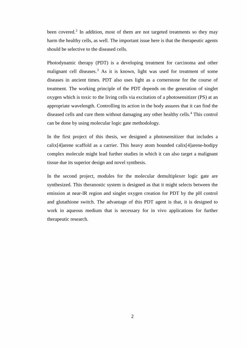
given wavelength, will be greatest. As it is seen in Figure 1, there are six types of
electronic transitions. Between these transitions π- π* and n- π* transitions require the
lower energy such that π- π* transition has ɛ values between 103 and 105 l mol cm-1
which is in the range of partially allowed transition. This property is due to the
orbital symmetry selection rule, it is spin allowed but not symmetry allowed. In
general, the transition is mentioned as fully allowed when the molar absorption
coefficient value is above the 105 l mol cm-1and it is spin forbidden but symmetry
allowed when the molar absorption coefficient value is above the 102 l mol cm-1 such
as n- π* transition.
Figure 1. Molecular Orbital Energies and Electronic Transitions in Organic
Molecules. 4

Absorption of light changes due to the variety of the substance that absorbs light.
Molar absorption coefficient, being the probability of absorption, has an effect on the
relationship between the intensity of light, concentration and the path length. As it is
stated in the Beer-Lambert Law, there is a linear relationship between the
absorbance, concentration and path length;
A=log(Iin/Iout)=ɛcl
where A is absorbance, Iin is the intensity of light that enters, Iout is the intensity of
light that is released, c is the concentration of the absorbing species and l is length of
path.
2.1.2 Physical Basis of Deactivation of Excited State
The molecule that is irradiated with a photon, that has proper energy in the range of
UV-Vis wavelength, elevates its electron to the higher energy excited state.
However, this excitation process is such a short living process that the physical
deactivation takes place immediately to give away that extra energy. There are two
main classes of this physical relaxation; intermolecular relaxation and intramolecular
relaxation.
Intermolecular relaxation processes includes vibrational relaxation, energy transfer
and electron transfer. Due to absorption of light molecules that have extra vibrational
energy will undergo a relaxation to the lowest vibrational level of the energy level
that is under interest, and this is named as the vibrational relaxation. The time scale
for a typical vibrational relaxation is between 10-13-10-9 s9. Energy transfer occurs
when the excited molecule transfer its energy to an acceptor group and electron
transfer occurs when the excited molecule interacts with the ground state acceptor
molecule and an ion pair is transferred. Electron transfer and energy transfer
concepts are going to be presented in the later subsections.
Intramolecular relaxation processes are classified as radiative transitions that include
fluorescence and phosphorescence and non-radiative transitions that include internal
conversion and intersystem crossing. There is an emission as the relaxation takes
place in the radiative transitions. If there is no emission during the relaxation then it
5
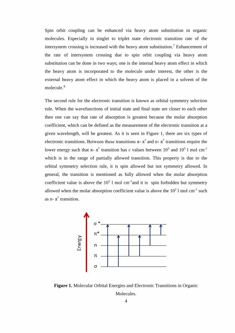
is called non-radiative transition. Fluorescence, an example of radiative transition,
takes place when there is a photon emission between the spin allowed states.
Phosphorescence is also a radiative transition between the spin forbidden states.
Fluorescence exists from the lowest vibrational level of the excited singlet state,
whereas phosphorescence exists from the lowest vibrational level of the excited
triplet state.
Internal conversion is a non-radiative relaxation between the excited electronic states
that have the same multiplicity. It is known that the energies of higher states are
close to each other. To give an example, the lowest vibration level of S3 state is close
to the highest vibrational level of the S2 state, so it there may exist a rapid energy
transfer between them. As the Kasha rule implies, because the relaxation to the
excited state with the same multiplicity is a very rapid process, dissipation of the
energy with luminescence emission are originated from the S1 at v=010.
Intersystem crossing occurs as a spin-forbidden transition between the vibrational
states that have the same total energy with different multiplicity. For example,
transition from S1 at v=0 to T1 at v=n where n is the highest vibrational level is an
intersystem crossing. There is an illustration of these relaxation processes in Figure
2.
Figure 2. Jablonski Diagram.
6

It is seen that the energy of the absorbed light is higher than energy of the emitted
light because of the energy loss of molecule before the emission. The difference
between these energy is called as Stokes shift.11 To be clear, it can be defined as the
difference between the band maximum of the absorption and the band maximum of
the emission of the same transition as it is seen in Figure 3.
Figure 3. Stokes’ shift.
2.1.2.1 Photoinduced Electron Transfer (PET)
The system that have photoinduced electron transfer (a.k.a. PET) has two main
components; one of them is known as fluorophore, the other one is known as
receptor. As its name implies fluoro means luminescence and phore means the one
that carries fluoro/light/luminescence and the fluorophore can be used as a dye that
has a property of re-emitting light due to the excitation. The receptor here is the
component that transfer its electron to the fluorophore or accepts an electron from the
fluorophore. These two components are separated from each other by an inert spacer
which breaks down the conjugation between them, but holds them together for the
chemical processes to be involved. Therefore, for a molecule to be a PET based
sensor, there should be a fluorophore, a spacer and a receptor. Because the electron
transfer occurs after the light absorption this mechanism is called as photoinduced
electron transfer. If the energy levels of the highest occupied molecular orbital
(HOMO) of the receptor and the lowest unoccupied molecular orbital (LUMO) of the
fluorophore are at the convenient energy then there is an option for the PET
mechanism to be materialize. PET occurs when the fluorophore that is excited has a
7

vacancy for an electron in its ground state. This vacancy in ground state can be filled
by the electron transferred from the receptor if the HOMO of the receptor has higher
energy than the HOMO of the fluorophore, or the excited fluorophore can transfer its
electron to the LUMO of the receptor where the LUMO of the receptor has lower
energy than the LUMO of the fluorophore.
Figure 4. Schematic PET mechanism.
As Figure 4 shows PET mechanism is a way of blocking the ordinary relaxation and
so quenching the emission. In this figure, receptor acts as an electron donor and
transfers its electron to the fluorophore and quenches emission. It is also shown that
the PET mechanism can be controlled by an analyte which prevents the receptor to
transfer its electron to the fluorophore. By this way controlled PET mechanisms
which can be on “on” or “off” state are emerged. It is clear on the left side of the
Figure 4 that when the receptor is free to transfer its HOMO electron to the vacant
HOMO of the fluorophore, the electron in the LUMO of the fluorophore cannot turn
back to its original position so emission is quenched and no fluorescence is observed.
On the right side of the Figure 4, it is seen that the receptor is bounded to a analyte,
so its HOMO energy is lower than HOMO energy of the fluorophore. Therefore, it is
not possible for receptor to transfer its electron to the fluorophore and the electron in
LUMO of the fluorophore turns back to vacant HOMO of fluorophore. Because of
this, there is fluorescence.
The natural and known example of PET mechanism is seen in photosynthesis.12 In
this process the sun pioneers the transfer of electrons which then causes charge
separation. The emerging free energy from these steps is used for the generation of
adenosine triphosphate. This example shows that oxidation-reduction processes of
molecules are related to the light absorption.
8

PET type sensors are widely used in supramolecular chemistry and become an
important research area for the molecular devices. 13,14. In this step, the diversity of
the molecular receptors becomes a necessary tool for a correct match between the
analyte and receptor, because a rapid PET is depended on the fluorophore-receptor
pair and the length of the spacer between them. 15 There are some molecules which
are developed for being PET sensors; for example crown ethers are modified for
being receptors for the alkali metal cations. The size of the crown ether determines
the cation selectivity; as the ring becomes bigger, the cation that will be selected gets
bigger.
Figure 5. Examples of PET sensors.
Simple PET sensors are shown in the Figure 5. The crown ether 1 that is modified
with an amine group and an anthracene is a simple PET sensor used for the metal
ions such as K+ and it is observed that its quantum yield increases with K+ ion in
methanol solution.16 Also some anthrylmethylamines like 11 are used as pH based
PET sensors. 17 In addition to these simple examples there are molecules which are
used as PET sensors such as calixarenes, cryptands and etc.
2.1.2.2 Intramolecular Charge Transfer (ICT)
The most important difference of intramolecular charge transfer (ICT) based
signaling systems from the PET systems is that there is no linker between the
fluorophore and the receptor, which means a direct integration of fluorophore and
receptor and so the receptor becomes a part of the π system of the fluorophore.
Because of this the orbitals of the chemical units overlapped well and this results in
one terminal to act as electron donor whereas the other terminal to act as electron
9
acceptor. When such a molecule is excited at a suitable wavelength the electron
density is redistributed which then results in a serious dipole in the molecule. There
exists an intramolecular charge transfer from electron donor to electron acceptor.
When an analyte binds to the receptor molecule in question there is an interaction
with the dipole of the excited state and this interaction can be observed with a change
in absorbance and emission spectra. 18
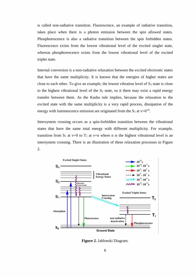
ICT is such a signaling mechanism that there is a blue shift or red shift according to
the properties of the molecules that plays a role in the formation of this process. If
there exists an electron donating group like amino group or hydroxy group onto the
receptor part that is directly conjugated to the fluorophore part, the interaction
between the receptor and a cation will cause a decrease in the electron donating
property of the receptor to the fluorophore which means also a decrease in the
conjugation. Therefore a blue shift in the absorption spectrum will be observed due
to the destabilization of the ICT system. In contrary, if the receptor unit has an
electron withdrawing group such as carbonyl group the interaction between the
receptor and a cation will increase its electron withdrawing property so a red shift
will be observed in the absorption spectrum due to the stabilization of the ICT
system 19 as it is represented in Figure 6.
Figure 6. Spectral changes in ICT based sensor
10
The essential reason behind the changes in emission and absorption spectra lies on
the charge dipole interactions. 20 When the molecule is excited, if it contains an
electron donating group this part will partially charged positively and this positive
charge will interact with the cation and so there will be a destabilization of the
excited state which means excited state will be more destabilized than the ground
state. In this situation, the gap between the excited state and the ground state
increases so there will be a blue shift in the emission and absorption spectra.
Oppositely, the reason of the red shift in the emission and absorption spectra is that
there is a decrease in the gap that is between the excited state and the ground state
due to the interaction between the fluorophore where the cation will stabilize the
excited state more than the ground state.15
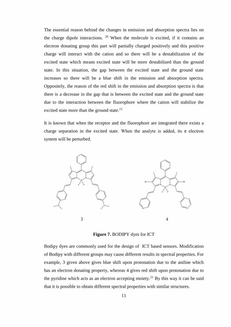
It is known that when the receptor and the fluorophore are integrated there exists a
charge separation in the excited state. When the analyte is added, its π electron
system will be perturbed.
Figure 7. BODIPY dyes for ICT
Bodipy dyes are commonly used for the design of ICT based sensors. Modification
of Bodipy with different groups may cause different results in spectral properties. For
example, 3 given above gives blue shift upon protonation due to the aniline which
has an electron donating property, whereas 4 gives red shift upon protonation due to
the pyridine which acts as an electron accepting moiety.21 By this way it can be said
that it is possible to obtain different spectral properties with similar structures.
11

2.1.2.3 Energy Transfer (ET)
When the existing energy is transferred to the ground state of a chromophore from
the excited state of another chromophore it is called as energy transfer.22 It is
represented in Figure 8. Here, the consignee of energy can be called as acceptor
which is then excited to its first singlet excited state, and the consignor of the energy
can be called as donor which transfers its excited state energy. Energy transfer is also
known as electron energy transfer (EET) and fluorescence resonance energy transfer
(FRET).
Because energy transfer is a kind of deactivation of excited state, it is effected by the
rate of the other deactivation ways and so the choice of an energy transfer system
should have meet properties to overcome the other patways.23 In addition, life time
of the excited state of donor should be longer than the time which is necessary for the
energy transfer. Here the most important thing that determines the mechanism of
energy transfer is the distance between the so called donor and the acceptor moieties.
Mainly according to this distance there exists two energy transfer systems; Dexter
type energy transfer system and Förster type energy transfer system.
Figure 8. Schematic representation of energy transfer systems.
For a Dexter type energy transfer to take place the distance between the donor and
the acceptor should be less than 10 Ǻ and for a Förster type energy transfer to take
place this distance should be in the range of 10 to 100 Ǻ. 23 There are some ways to
characterize the energy transfer such as comparison of quantum yields, relative
lifetimes, emission of acceptor increase, emission of donor decrease, etc.
2.1.2.3.1 Dexter Type Energy Transfer
12
The orbital interaction between the donor and acceptor moieties is the decisive fact in
Dexter type energy transfer. 24 There should be a conjugated linker between the
donor and the acceptor to supply an exchange of electrons between the HOMOs and
LUMOs of the donor and acceptor. As it is implied a short distance between the
donor and the acceptor such as 10 Å is necessary for the orbital interactions. As the
distance between increases the rate constant of energy transfer decreases
exponentially;
kET = K J exp(-2RDA / L)
Here, kET represents rate constant of energy transfer, K stands for orbital interaction,
J symbolizes overlap integral between donor emission and acceptor absorbance, RDA
represents the separation between the donor and acceptor and L stands for the van
der Waals radius. 23
In other words, Dexter type energy transfer is depended on the interaction between
the orbitals of donor and acceptor that leads to electron exchange from HOMO of the
donor to LUMO of the acceptor. 25
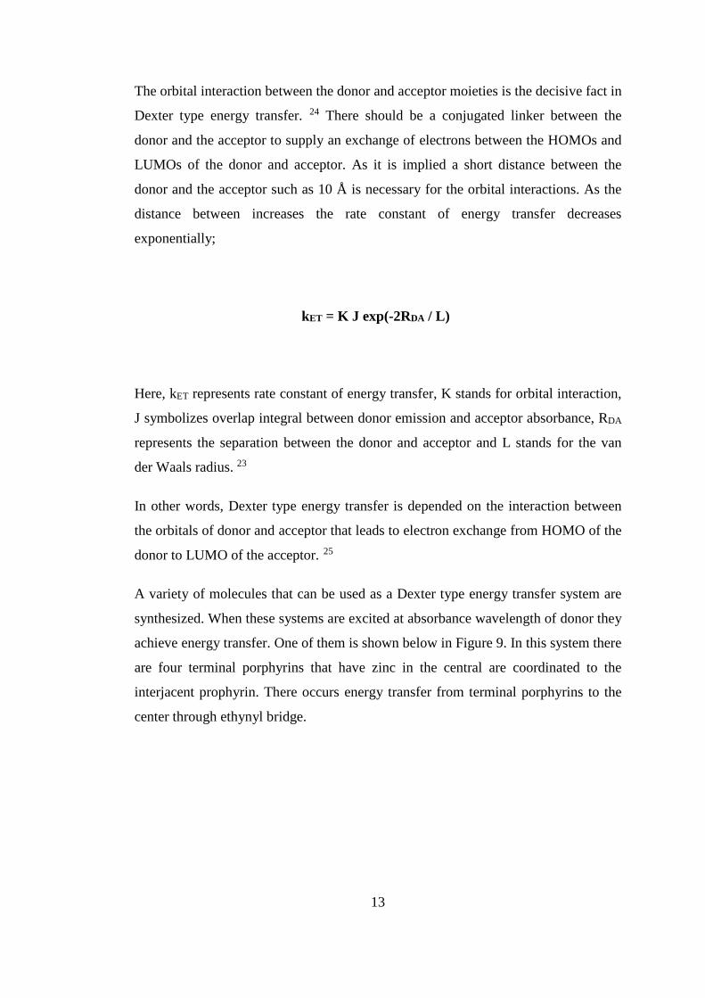
A variety of molecules that can be used as a Dexter type energy transfer system are
synthesized. When these systems are excited at absorbance wavelength of donor they
achieve energy transfer. One of them is shown below in Figure 9. In this system there
are four terminal porphyrins that have zinc in the central are coordinated to the
interjacent prophyrin. There occurs energy transfer from terminal porphyrins to the
center through ethynyl bridge.
13
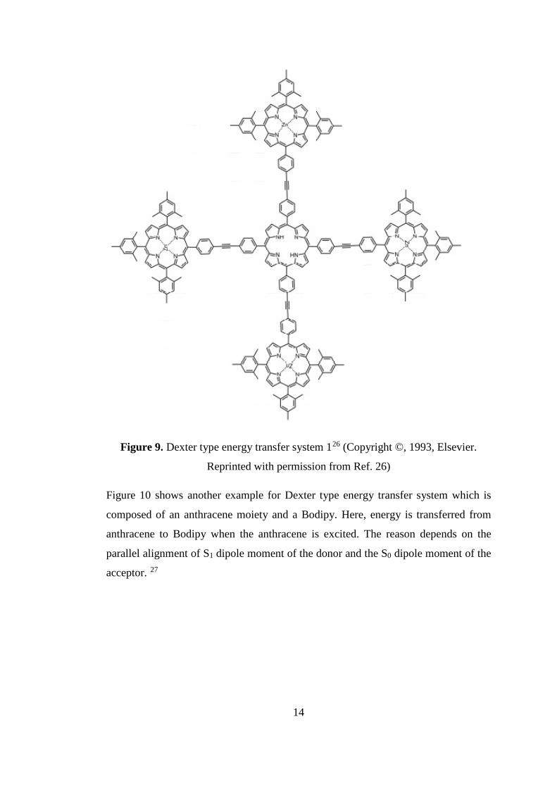
Figure 9. Dexter type energy transfer system 126 (Copyright ©, 1993, Elsevier.
Reprinted with permission from Ref. 26)
Figure 10 shows another example for Dexter type energy transfer system which is
composed of an anthracene moiety and a Bodipy. Here, energy is transferred from
anthracene to Bodipy when the anthracene is excited. The reason depends on the
parallel alignment of S1 dipole moment of the donor and the S0 dipole moment of the
acceptor. 27
14

Figure 10. Dexter type energy transfer system 228 (Copyright ©, 2006, Elsevier.
Reprinted with permission from Ref. 28)
2.1.2.3.2 Förster Type Energy Transfer
Förster type energy transfer is known as Förster resonance energy transfer (FRET)
and also as electronic energy transfer (EET). There is a non-conjugated linker
between the donor and the acceptor. In contrast to Dexter type energy transfer orbital
interaction between the donor and the acceptor is not a remarkable property because
the distance between them is large. There are three important parameters for FRET;
one of them is the distance between donor and acceptor moieties, the second one is
the spectral overlap between the emission of donor and the absorption of acceptor,
and the third one is the relative orientation of the transition dipoles of these moieties. 29, 30, 31 They have an important role in the occurance of energy transfer, rate of
energy transfer and the efficiency of the energy transfer.
In FRET mechanism, the energy released by the relaxation of the donor’s electron
from its LUMO to HOMO is used for the excitation of the acceptor’s electron from
HOMO to LUMO. The emission wavelength of the donor moiety should match with
energy absorbed by the acceptor moiety for the existence of spectral overlap. The
equations below shows the dependence of FRET on distance and overlap integral;
EFRET = [1 + (R/Ro)6]-1
Ro6 = [9 Qo (ln10) κ2 J] / [128 π5 n4 NA]
where Ro refers to the distance between the donor and acceptor moieties and called
as Förster radius, R is the separation between the FRET moieties. Here, the quantum 15
yield of FRET donor is represented as Qo, the orientation factor of dipole is the
overlap integral is J, the refractive index of the medium is n, and the Avagadro’s
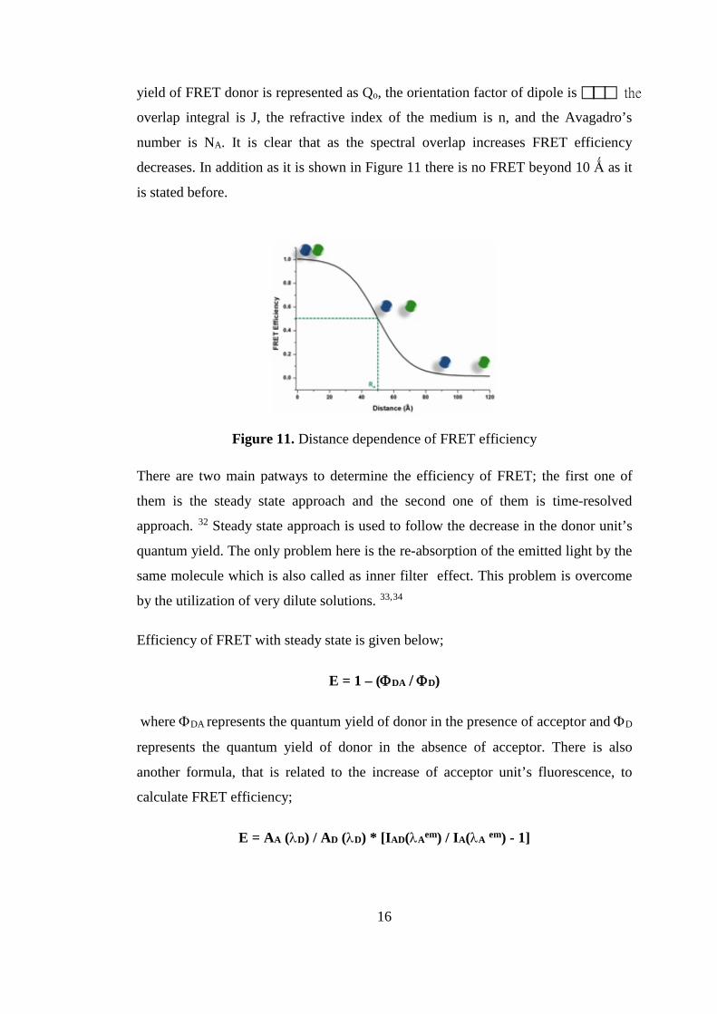
number is NA. It is clear that as the spectral overlap increases FRET efficiency
decreases. In addition as it is shown in Figure 11 there is no FRET beyond 10 Ǻ as it
is stated before.
Figure 11. Distance dependence of FRET efficiency
There are two main patways to determine the efficiency of FRET; the first one of
them is the steady state approach and the second one of them is time-resolved
approach. 32 Steady state approach is used to follow the decrease in the donor unit’s
quantum yield. The only problem here is the re-absorption of the emitted light by the
same molecule which is also called as inner filter effect. This problem is overcome
by the utilization of very dilute solutions. 33,34
Efficiency of FRET with steady state is given below;
E = 1 – (ΦDA / ΦD)
where ΦDA represents the quantum yield of donor in the presence of acceptor and ΦD
represents the quantum yield of donor in the absence of acceptor. There is also
another formula, that is related to the increase of acceptor unit’s fluorescence, to
calculate FRET efficiency;
E = AA (λD) / AD (λD) * [IAD(λAem) / IA(λA em) - 1]
16
where AA is the absorbance of acceptor and AD is the absorbance of donor at a
wavelength at which the absorbance of donor is maximum, integrated area of the
acceptor is denoted as IAD and IAD in the presence and absence of donor at λA em,
respectively.
FRET efficiency calculation is much more accurate with the second pathway; time
resolved approach that uses time-resolved emissions of acceptor and donor as its
name implies. FRET efficiency can be calculated by using the formula below 32;
E = τD*kFRET / (1 + τD*kFRET)
kFRET = 1/τDA - 1/τD
where τDA and τD represents lifetime of the excited state of donor in the presence
and absence of acceptor, respectively.
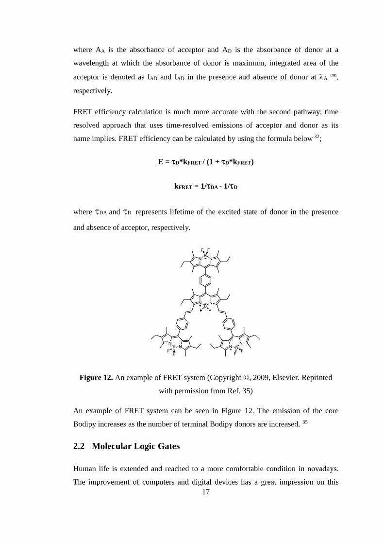
Figure 12. An example of FRET system (Copyright ©, 2009, Elsevier. Reprinted
with permission from Ref. 35)
An example of FRET system can be seen in Figure 12. The emission of the core
Bodipy increases as the number of terminal Bodipy donors are increased. 35
2.2 Molecular Logic Gates
Human life is extended and reached to a more comfortable condition in novadays.
The improvement of computers and digital devices has a great impression on this 17

development of life conditions. Their function and contribution in sharing
information, saving and generating data and communication between people all
around the world can be shown as the base of the civilization. Contemporary
technology is proceeded enough to use electronic signal as a carrier for these kind of
information sharing, storing and communication by means of miniaturization.
Information is encoded as a series that is composed of a combination of zeros and
ones which represent low and high voltage, respectively, in this kind of digital
systems. 36,37
The fundamental building blocks of silicon circuitry depends on the logic gates
which are a kind of electronic devices and carry out Boolean functions. 38 There
should be one or more logical inputs for a logical operation and for the creation of an
output. There are 16 different types of Boolean logic operations. 39 Here, the most
commonly used logic operations are; AND, OR, NOR, XOR, NAND, XNOR, INH
and NINH. The interconnection of AND, OR, XOR and INH which are the basic
logic operations results in the others; NOR, NAND, XNOR and NINH operations.
Table 1 displays the truth tables for all these commonly used logic gate operations. If
and only if the both inputs are 1 then the output is 1 which indicates a state above a
specified threshold, otherwise the output is 0 which indicates a state below a
specified threshold in any combination of inputs in an AND gate. In an OR gate, it is
enough for a one input to be 1 for the output to be 1. The output will be 0 only when
the two inputs are 0. In an XOR gate, when the both inputs are at the same logic state
the output becomes 0, if the inputs have different state from each other the output is
1. For an INH gate, one of the input determines whether the output is 1 or 0. It is
seen that the outputs of NAND, NOR, XNOR and NINH are the reverse of AND,
OR, XOR and INH gates, respectively.
There are also more complex logic gate systems that are composed of the integration
of Boolean logic operations. Some of them are half adder, half substractor, full adder,
full substractor, multiplexer and demultiplexer. 40
18

Inp1 Inp2 Outp Outp Outp Outp Outp Outp Outp Outp
A B OR AND XOR INH NOR NAND XNOR NINH
0 0 0 0 0 0 1 1 1 1
1 0 1 0 1 0 0 1 0 1
0 1 1 0 1 1 0 1 0 0
1 1 1 1 0 0 0 0 1 1
Table 1. Truth tables for the commonly used logic operators that have 2 inputs
Transistors are the main components of the logic gates in computers which makes
them to be used as electronic switches. When the current is turned on in the
transistor, it is symbolized as 1, when it is turned off it is symbolized as 0. 41 With
the emergency of silicon based transistors there occurred a chance to combine the
transistors in a small chip which makes it possible to profit from space, energy, cost
and performance. 42
Molecular logic devices are the extended version of the macroscopic logic devices.
Molecules can be synthesized and designed in such a way that they can be capable of
performing some special functions. There is a need for energy and signal to operate
and communicate with the operator. 43 The energy here can be light such as
luminescence, electrical energy or chemical energy and electronic and/or nuclear
rearrangements are used to operate. 43 The prominent study in molecular logic gates
was proposed by de Silva in 1993 which then gained a great importance in the area
of molecular mimicry. 1 There should be an ion responsive molecule to carry out a
logical operation due to a given input in molecular logic gates. The output of the
molecular logic system is followed by a signal which might be fluorescent or an
other optical signal. Fluorocesce phenomenon is opted in general because of its
advantages on selectivity and sensitivity. With help of chemical stimuli fluorescence
switches between “on” and “off” states. It is obvious that these kind of molecular
logic gates are design to work with on/off switching systems such as photoinduced
electron transfer, internal charge transfer and energy transfer.
19
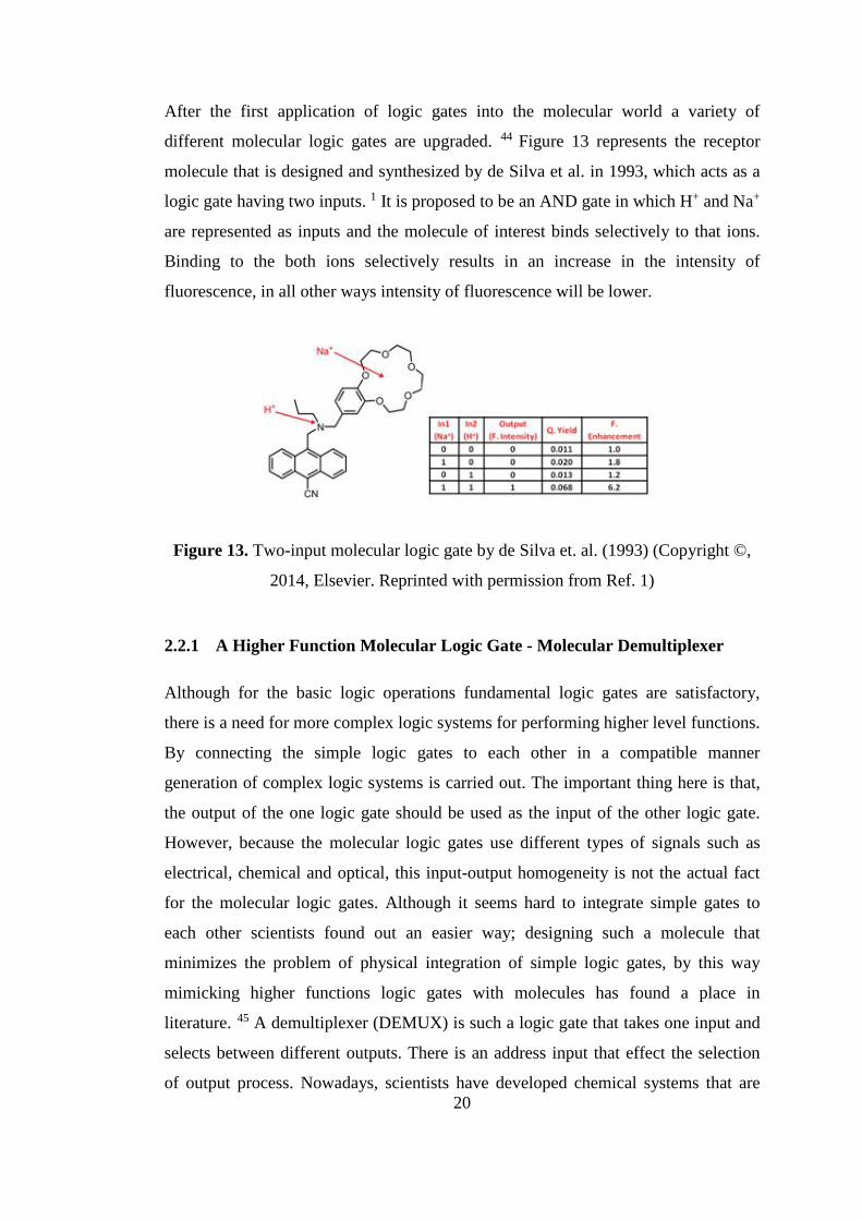
After the first application of logic gates into the molecular world a variety of
different molecular logic gates are upgraded. 44 Figure 13 represents the receptor
molecule that is designed and synthesized by de Silva et al. in 1993, which acts as a
logic gate having two inputs. 1 It is proposed to be an AND gate in which H+ and Na+
are represented as inputs and the molecule of interest binds selectively to that ions.
Binding to the both ions selectively results in an increase in the intensity of
fluorescence, in all other ways intensity of fluorescence will be lower.
Figure 13. Two-input molecular logic gate by de Silva et. al. (1993) (Copyright ©,
2014, Elsevier. Reprinted with permission from Ref. 1)
2.2.1 A Higher Function Molecular Logic Gate - Molecular Demultiplexer
Although for the basic logic operations fundamental logic gates are satisfactory,
there is a need for more complex logic systems for performing higher level functions.
By connecting the simple logic gates to each other in a compatible manner
generation of complex logic systems is carried out. The important thing here is that,
the output of the one logic gate should be used as the input of the other logic gate.
However, because the molecular logic gates use different types of signals such as
electrical, chemical and optical, this input-output homogeneity is not the actual fact
for the molecular logic gates. Although it seems hard to integrate simple gates to
each other scientists found out an easier way; designing such a molecule that
minimizes the problem of physical integration of simple logic gates, by this way
mimicking higher functions logic gates with molecules has found a place in
literature. 45 A demultiplexer (DEMUX) is such a logic gate that takes one input and
selects between different outputs. There is an address input that effect the selection
of output process. Nowadays, scientists have developed chemical systems that are 20
capable of operating as DEMUX by combining organic molecules, lasers and
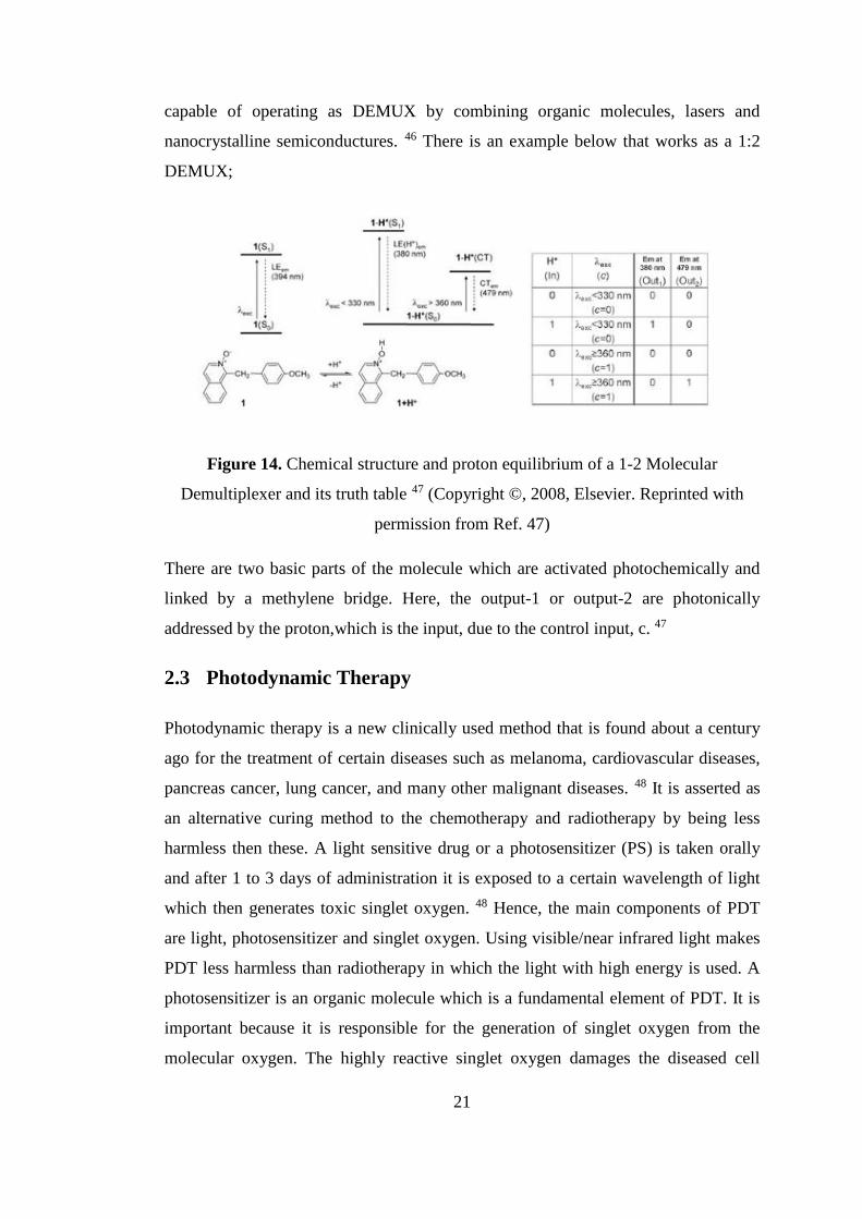
nanocrystalline semiconductures. 46 There is an example below that works as a 1:2
DEMUX;
Figure 14. Chemical structure and proton equilibrium of a 1-2 Molecular
Demultiplexer and its truth table 47 (Copyright ©, 2008, Elsevier. Reprinted with
permission from Ref. 47)
There are two basic parts of the molecule which are activated photochemically and
linked by a methylene bridge. Here, the output-1 or output-2 are photonically
addressed by the proton,which is the input, due to the control input, c. 47
2.3 Photodynamic Therapy
Photodynamic therapy is a new clinically used method that is found about a century
ago for the treatment of certain diseases such as melanoma, cardiovascular diseases,
pancreas cancer, lung cancer, and many other malignant diseases. 48 It is asserted as
an alternative curing method to the chemotherapy and radiotherapy by being less
harmless then these. A light sensitive drug or a photosensitizer (PS) is taken orally
and after 1 to 3 days of administration it is exposed to a certain wavelength of light
which then generates toxic singlet oxygen. 48 Hence, the main components of PDT
are light, photosensitizer and singlet oxygen. Using visible/near infrared light makes
PDT less harmless than radiotherapy in which the light with high energy is used. A
photosensitizer is an organic molecule which is a fundamental element of PDT. It is
important because it is responsible for the generation of singlet oxygen from the
molecular oxygen. The highly reactive singlet oxygen damages the diseased cell
21
which is exposed to the light. To summarize, it can be said that by activating the PS
by photons with appropriate energy results in the formation of singlet oxygen from
the molecular oxygen. The place of the PS determines where the cellular attack of
singlet oxygen will occur, it can damage lipids, DNA or proteins oxidatively. 49 the
cellular response is given as apoptosis or necrosis and the vascular supply is broken
down so hypoxia or activation of immune system takes place. 50,51 In PDT, either a
laser source of light emitting diodes (LEDs) that are red or near infrared are used as a
light sources because these red or near IR light penetrates to the tissues better. 52
2.3.1 A Brief History of Photodynamic Therapy
The story of PDT began with the observation of some chemicals caused cell death in
the presence of certain intense light about a century ago. Oscar Raab, a
pharmacology student, observed that a certain bacteria was dead due to the toxic
affect of acridine red molecule when it was subjected to the light. 53 He found out
that a flurorophore was needed for the corresponding light induced toxicity. After the
first emergency of PDT, eosin dye was used as the first PS for the medical treatment
of skin cancer by Tappeiner and Jesionek. 54 Year 1979 has a great importance for
the development and understanding of PDT. It is the year that the mechanism of
oxygen dependent toxicity of photoactive molecules was found due to monitoring the
generation of singlet oxygen by electron spin resonance technique. 55 Meyer-Betz, a
scientist, made the first trial of human PDT on himself and suffered from an
extensive phototoxic reactions and felt extreme pain. 56 The clinical application of
PDT was performed by Dougherty et al. in 1978. 57 After that, the first PS approved
by FDA was photofrin. The commercialization of photofrin was completed in
Canada for the treatment of bladder cancer ,n 1993. By being the most used PDT
drug, it has been approved in USA for oesophagel cancer, in Netherlands and France
for lung cancer, in Japan for gastric cancer and in Germany for early stage lung
cancer. . Following this, a lot of PS were approved by FDA and this leaded to a great
success in the treatment of diseases by PDT.
22
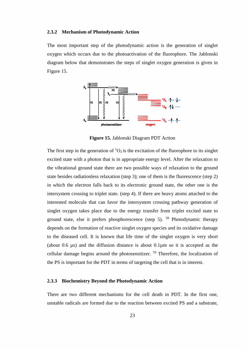
2.3.2 Mechanism of Photodynamic Action
The most important step of the photodynamic action is the generation of singlet
oxygen which occurs due to the photoactivation of the fluorophore. The Jablonski
diagram below that demonstrates the steps of singlet oxygen generation is given in
Figure 15.
Figure 15. Jablonski Diagram PDT Action
The first step in the generation of 1O2 is the excitation of the fluorophore to its singlet
excited state with a photon that is in appropriate energy level. After the relaxation to
the vibrational ground state there are two possible ways of relaxation to the ground
state besides radiationless relaxation (step 3); one of them is the fluorescence (step 2)
in which the electron falls back to its electronic ground state, the other one is the
intersystem crossing to triplet state. (step 4). If there are heavy atoms attached to the
interested molecule that can favor the intersystem crossing pathway generation of
singlet oxygen takes place due to the energy transfer from triplet excited state to
ground state, else it prefers phosphorescence (step 5). 58 Photodynamic therapy
depends on the formation of reactive singlet oxygen species and its oxidative damage
to the diseased cell. It is known that life time of the singlet oxygen is very short
(about 0.6 µs) and the diffusion distance is about 0.1µm so it is accepted as the
cellular damage begins around the photosensitizer. 59 Therefore, the localization of
the PS is important for the PDT in terms of targeting the cell that is in interest.
2.3.3 Biochemistry Beyond the Photodynamic Action
There are two different mechanisms for the cell death in PDT. In the first one,
unstable radicals are formed due to the reaction between excited PS and a substrate,
23
which is called as a biomolecule. These radicals are used to generate singlet oxygen.
In the second one, there is an energy transfer from excited PS to oxygen that leads to
the formation of singlet oxygen. It is accepted that both of the mechanisms occurs
concurrently. 50 The newly generated singlet oxygen (1O2) reacts with biomolecules
such as membrane lipids whose structure and integrity are changed due to the
formation of radicals and other destructive chemicals that lead to an increase in the
oxidative stress in cell. 60 Hydroxyl radicals generated by reactions of 1O2 attack to
the deoxyribose sugar and bases of DNA and this mutation causes an immediate cell
death. 61
Cell death in PDT can take place in two different morphological ways; apoptosis and
necrosis. 62 Apoptosis is known as the programmed cell death. Apoptosis causes
some characteristic morphological changes in the cell, such as; DNA fragmentation,
blebbing, cell shrinkage and chromatin condensation. Caspases, as known as
proteolytic enzymes exist in all cells as inactive precursors or procaspases and
activated by other caspases cleavage process and produces a proteolytic caspase
cascade, intercede apoptosis by cleaving specific proteins in cytoplasm and nucleus. 63 It is activated with an apoptotic signal which is triggered by radiation, an increase
in intracellular calcium concentration, viral infection and lack of nutrition. With the
initiation of the activation intracellular adaptor molecules begin to aggregate and
activate procaspases, and the cell death exist. Necrosis is the second way of cell
death by PDT. Unlike apoptosis, it is known as being traumatic and unnatural cell
death. It can be fatal to the organism. Cell membrane integrity is lost and products of
cell death are set free in the cell membrane, in necrosis. Both apoptosis and necrosis
can be observed as outcome of the PDT.
2.3.4 Properties of Photosensitizers
There are some special requirements for the photosensitizer which is sent to the cell
before the light is applied for being an efficient agent. For the PDT takes place, there
should be a generation of singlet oxygen which requires appropriate physical and
chemical properties in a specific molecule. The transition from triplet ground state of
molecular oxygen to singlet oxygen excited state is spin forbidden. Its probability is
increased with the spin-orbit (SO) coupling which provides a singlet character to the 24

triplet state by mixing the spin angular momentum and the orbital angular
momentum.
Hso=[(e2Z4)/(2a0m2c2n3)]LS
SO-Hamiltonian formula is given64 above shows that SO-Hamiltonian term is
proportional to the fourth power of atomic number , Z, where e is charge of electron,
a0 is Bohr’s radius, m is the mass of electron, c is the speed of light, n is the principle
quantum number, L is the angular momentum and S is the spin operator. It is clear
that heavy atom attachment to the molecule of interest increases the spin-orbit
coupling and so the spin forbidden transition from singlet to triplet state. Heavy atom
effect on efficacy of the photosensitizer was verified on BODIPY dyes with bromine
attachment by O’Shea et al. 65 Therefore, photosensitizers with heavy atoms have a
better singlet oxygen generation capability.
In addition, because of the reactive singlet oxygen generated during the PDT action
most of the photosensitizers are degraded which is called photobleaching. Hence,
photosensitizer should be designed as a photostable molecule for the sake of PDT.
The depth of the penetration of light to the tissue is another important issue. It is
known that penetration of light is decreased substantially beyond 1150 nm because
of the absorbance of water. Visible light is absorbed by flavins, collogens, melanin
and hemoglobins. Near UV region is absorbed by some aromatic amino acids such as
phenylalanine, tyrosine and tryptophan. When all these conditions are considered it
gives out that maximum penetration of light is obtained in the range of 620-850 nm
which is called therapeutic window. To produce reactive singlet oxygen the chosen
or designed photosensitizer should absorb light in this region sufficiently. 66
Besides the properties mentioned above a photosensitizer should meet the other
requirements for biological application such as it should be biocompatible,
effervescent and should have dark toxicity which means it is inactive until the light is
exposured.
25
CHAPTER 3
3 PEGylated Calix[4]arene as a Carrier for a Bodipy-based
Photosensitizer
This work is partially described in the following publication
Yusuf Çakmak, Tuğrul Nalbantoğlu, Tuğçe Durgut, Engin U. Akkaya
Tet. Lett., 2014, Vol. 55, pp. 538-540
3.1 Introduction
Photodynamic therapy (PDT) is accepted as an alternative method to the other
traditional therapeutic methods that includes chemotherapy, radiation therapy and
surgery because of being less invasive than them.50 PDT is a selective method by
performing the cytotoxic action only in the presence of light, sensitizer and dissolved
oxygen. Its selectivity depends on the capability of controlling the region of
irradiation.
There is a great interest in generating and controlling the photodynamic action of late
years. In addition, there is an increase in the introduction of novel chromophore
families such as Bodipy dyes as potential photosensitizers. 67 Bodipy dyes are seen
as one of the most promising and efficient photosensitizers although they were
ascribed to be chemically and photochemically stable hence unavailable to form
triplet state and so the interaction with ambient oxygen is reduced which is necessary
for PDT at first. However, with incorporation of heavy atoms such as iodine or with
the increase in degeneracy of the excited state frontier orbitals an efficient
photosensitizer can be obtained from a Bodipy dye. 68
The wavelength of irradiation is the other important point that should be considered.
The dyes with weak absorptions in the red end of the visible spectrum where the
mammalian tissues are most transparent are preferred in the PDT studies. Studies on
obtaining dyes that have absorptions in the red and near IR region of the spectrum
are acceptable in this point of view. Porphyrin family is an example to these kinds of
dyes. 69 Bodipys give a chance to tune their absorption bands in a wide range. For
26

example, by substituting one or two styryl groups to a Bodipy dye its absoption peak
can be moved between 500 nm and 850 nm. 70 With the consideration of this
practical property of the Bodipy dye we come up with a new type of scaffold
carrying this dye and also enabling it to absorb near IR light.
Furthermore, calix[4]arene which has a hydrophobic core and special geometry is a
very useful molecule for organic chemists. Up to this point in time there are only a
few examples that incorporate Bodipy dyes and calix[4]arenes. Akkaya et al. have
synthesized a bodipy around a monoformylated tetrahydroxycalix[4]arene for pH
sensing with the help of the working principle of photoinduced electron transfer
(PeT).71 In this design, the bodipy is synthesized around the formyl unit which
ensures obtaining the bodipy unit attached to the calix[4]arene unit. It is notable that
π conjugation is faded due to the orthogonalty of the phenyl of calix[4]arene and the
bodipy. By this way absorption spectrum of the bodipy does not change. In our
design, we improved the aforementioned system in terms of absorbance, application,
route of synthesis and the number of bodipy units attached to the calix[4]arene
backbone.
3.2 Design and Synthesis
Incorporation of maximum number of bodipy molecules to the calix[4]arene scaffold
is the main principal of our design. Our aim was putting forward a new type of
molecule that would function effectively in other potential applications. The number
of bodipy unit is important for the enhancement of the phototoxic effect. Therefore,
our design of PS (Fig. 16), there are two bodipy chromophores that are attached to
the calix[4]arene core.
27
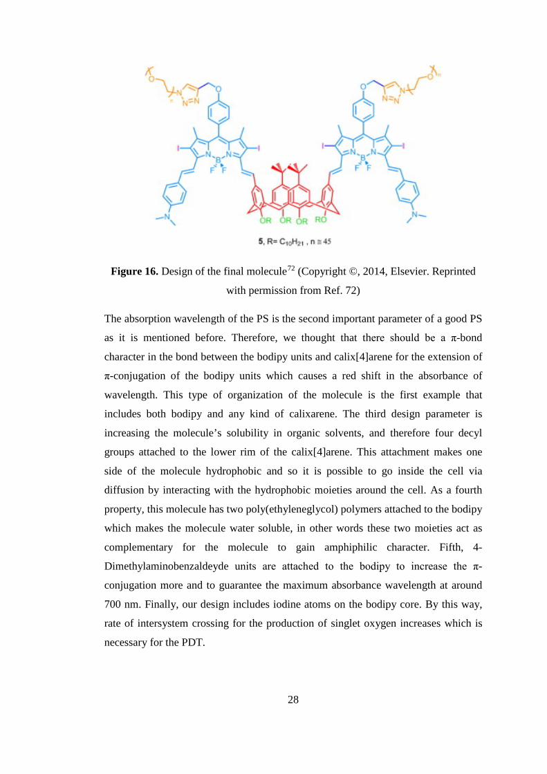
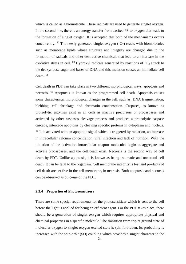
Figure 16. Design of the final molecule72 (Copyright ©, 2014, Elsevier. Reprinted
with permission from Ref. 72)
The absorption wavelength of the PS is the second important parameter of a good PS
as it is mentioned before. Therefore, we thought that there should be a π-bond
character in the bond between the bodipy units and calix[4]arene for the extension of
π-conjugation of the bodipy units which causes a red shift in the absorbance of
wavelength. This type of organization of the molecule is the first example that
includes both bodipy and any kind of calixarene. The third design parameter is
increasing the molecule’s solubility in organic solvents, and therefore four decyl
groups attached to the lower rim of the calix[4]arene. This attachment makes one
side of the molecule hydrophobic and so it is possible to go inside the cell via
diffusion by interacting with the hydrophobic moieties around the cell. As a fourth
property, this molecule has two poly(ethyleneglycol) polymers attached to the bodipy
which makes the molecule water soluble, in other words these two moieties act as
complementary for the molecule to gain amphiphilic character. Fifth, 4-
Dimethylaminobenzaldeyde units are attached to the bodipy to increase the π-
conjugation more and to guarantee the maximum absorbance wavelength at around
700 nm. Finally, our design includes iodine atoms on the bodipy core. By this way,
rate of intersystem crossing for the production of singlet oxygen increases which is
necessary for the PDT.
28
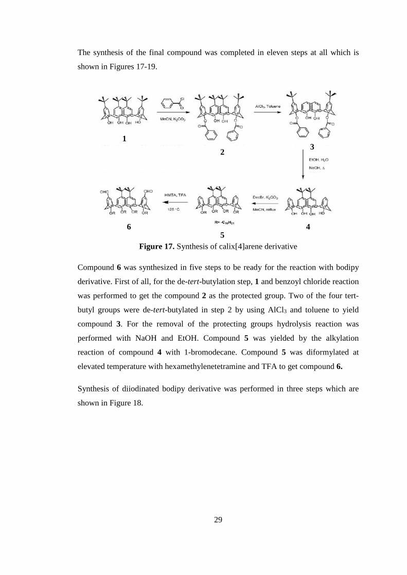
The synthesis of the final compound was completed in eleven steps at all which is
shown in Figures 17-19.
Figure 17. Synthesis of calix[4]arene derivative
Compound 6 was synthesized in five steps to be ready for the reaction with bodipy
derivative. First of all, for the de-tert-butylation step, 1 and benzoyl chloride reaction
was performed to get the compound 2 as the protected group. Two of the four tert-
butyl groups were de-tert-butylated in step 2 by using AlCl3 and toluene to yield
compound 3. For the removal of the protecting groups hydrolysis reaction was
performed with NaOH and EtOH. Compound 5 was yielded by the alkylation
reaction of compound 4 with 1-bromodecane. Compound 5 was diformylated at
elevated temperature with hexamethylenetetramine and TFA to get compound 6.
Synthesis of diiodinated bodipy derivative was performed in three steps which are
shown in Figure 18.
1 2 3
6 5
4
29

Figure 18. Synthesis of diiodinated bodipy derivative
First step is the reaction of the propargyl bromide and 4-hydroxybenzaldehyde.
Product of this reaction was reacted with 2,4-dimethylpyrrole with an ordinary
bodipy synthesis procedure and yielded alkynyl bodipy derivative, which was then
diiodinated with iodine and iodic acid to yield compound 7.
Compound 8 was obtained due to the Knoevenagel reaction of compound 6 and
compound 7. (Fig. 19). Another typical Knoevenagel reaction on compound 8 with
4-(Dimethylamino)benzaldehyde yielded in compound 9, which then forms
compound 10 due to a click reaction with pre-prepared PEG-N3.
1H NMR, 13C NMR and ESI or MALDI mass spectroscopy were used for the
characterization of the compounds. Because of the large molecular weights of the
compound 9 and compound 10 characterization of them was hard. However, by
comparing their 1H NMR data analysis, the structure of the photosensitizer,
compound 10 was verified. (Fig. 20)
7
30

Figure 19. Schematic synthesis of the photosensitizer, compound 10
Figure 20. Comparative 1H NMR data analysis of compound 9 and compound 10
8 9
10
31

A comparative 1H NMR spectra of compound 9 and compound 10 are given in
Figure 20. There are three differences in aliphatic regions of the 1H NMR spectra of
these two compounds due to the successful final click reaction. First of all,
disappearance of the acetylenic proton at 2.61 ppm (proton a, in Fig. 20) is a proof of
the accomplishment of the click reaction. The second difference is that, a methylene
proton that belongs to the PEG group linked directly to the triazole is appeared at
4.58 ppm (proton d, in Fig.20). And lastly, there is a shift of methylene bridge
protons which connects the triazole unit to the phenoxy unit of the Bodipy from 4.89
ppm to 5.25 ppm is observed (proton shifting from b to e, in Fig. 20). This kind of a
peak shift is also observed in a similar compound that is synthesized by Erbas et al.73
In the aromatic region of the spectra, there exists a triazole proton at 7.90 ppm.
(proton e, in Fig. 20). Because the electronic structure and the geometric shape of the
molecule do not change too much, there are no such important changes in the
aromatic region of the 1H NMR spectra.
3.3 Results and Discussion
After synthesizing the photosensitizer, compound 10, we focused on the PDT
experiments. For this aim, we planned two experiments; one of them is in organic
medium and the other one is in the aqueous medium because our final compound is
amphiphilic. We used 1,3-diphenylisobenzofuran (DPBF) which is known as a
universal oxygen scavenger compound for the experiments took place in the organic
medium. Maximum absorbance of DPBF in a broad range of organic solvent types is
about at 410 nm and intensity of the absorbance peak at 410 nm is decreased due to
the reaction with oxygen that is generated by the PS in action. Therefore, we focused
on the decrease in the intensity of the peak at 410 nm.
First of all, we performed control experiments without PS, compound 10. We used
only DPBF (10µM), light and bubbled air (5 min.) in isopropanol. We started the
photodynamic experiments in dark by withdrawing light and recording the
absorbance spectra for 15 minutes. After that, irradiation with LED light array of 725
nm was applied with 5 min time intervals for 60 min. The normalized absorbance
graph (Black dotted line in Fig. 21, below) shows that the absorbance of trap
32

molecule does not change with time, by proving that there is no cytotoxic 1O2
formation.
Secondly, we included compound 10 (46 nM) to the control experiments in
isopropanol. For this case, again 15 min. dark toxicity experiment was applied and it
was observed that the absorbance did not change with time and there was no
cytotoxic 1O2 formation. (Red dotted line in Fig. 21) Then, it was irradiated by 725
nm light for 60 min. with 5 min time intervals again for the photodynamic activity.
There was a successful decrease in the absorbance of scavenger with time which was
a proof of 1O2 formation.
Figure 21 Change in absorbance spectrum of DPBF in the absence of compound 10
and in the presence of compound 10 in IPA; first 15 min dark and then 60 min
irradiation with 725 nm LED array (above). Normalized absorbance vs. time graph
of DPBF; control experiment without (black dotted line) and with (red dotted line)
compound 10 (below). (Copyright ©, 2014, Elsevier. Reprinted with permission
from Ref. 72)
Afterward, we performed singlet oxygen experiments in aqueous medium. Because
DPBF is not soluble in such polar solvents we needed a water soluble trap molecule.
For this reason we synthesized an anthracene derivative substituted with malonic
acid groups (2,2’-(anthracene-9,10-diylbis(methylene))dimalonic acid, ADMDA).
Figure 22 shows the schematic synthesis of ADMDA that tracks 1O2 formation.
Dioxygen bridges are formed as a result of the reaction with 1O2 and there is a
decrease in the absorbance signal around 380 nm of the original compound.
33
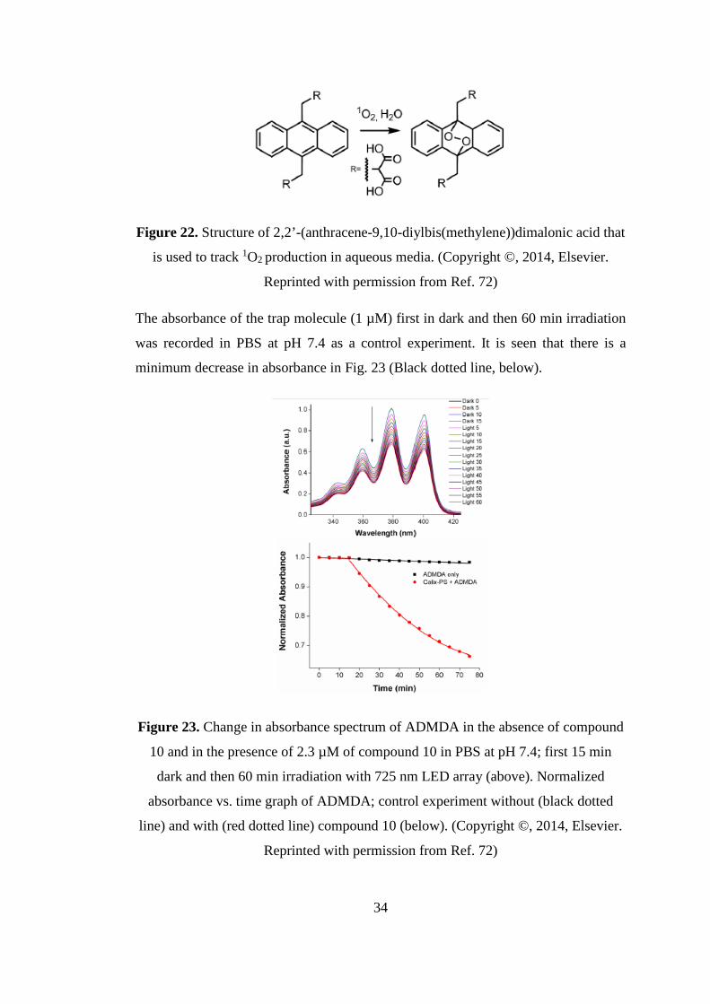
Figure 22. Structure of 2,2’-(anthracene-9,10-diylbis(methylene))dimalonic acid that
is used to track 1O2 production in aqueous media. (Copyright ©, 2014, Elsevier.
Reprinted with permission from Ref. 72)
The absorbance of the trap molecule (1 µM) first in dark and then 60 min irradiation
was recorded in PBS at pH 7.4 as a control experiment. It is seen that there is a
minimum decrease in absorbance in Fig. 23 (Black dotted line, below).
Figure 23. Change in absorbance spectrum of ADMDA in the absence of compound
10 and in the presence of 2.3 µM of compound 10 in PBS at pH 7.4; first 15 min
dark and then 60 min irradiation with 725 nm LED array (above). Normalized
absorbance vs. time graph of ADMDA; control experiment without (black dotted
line) and with (red dotted line) compound 10 (below). (Copyright ©, 2014, Elsevier.
Reprinted with permission from Ref. 72)
34

After the control experiments a PBS solution at pH 7.4 was prepared. Because the
compound 10 did not dissolved in PBS well because of the polar ethylene glycol
units we first dissolved in tiny amount of ethanol and then studied with PBS. There
was no precipitation and it worked well. We used 2.3 µM of compound 10 for the
photodynamic activity experiment in PBS. It was mandatory to use 50 folds of
compound 10 due to the short lifetime of the 1O2 (2 µs) in aqua. The same procedure
with organic media was applied to the this experiment; there was no change in
absorbance in the first 15 min dark experiment, and a sharp decrease in the
absorbance with 60 min irradiation with 725 nm LED array (Figure 23).
Eventually, we observed the singlet oxygen formation and photodynamic activity in
both organic (IPA) and aqueous (10% EtOH in PBS) media due to amphiphilic
structure of the calix-bodipy photosensitizer.
3.4 Conclusion
Initially, we came up with an idea such that getting a carrier molecule having four
bodipy units. In addition, we were planning to link this carrier molecule to an
antibody of a cancer tissue to recognize it and act as a targeting group. Because
characterization of the structure of antibody, reacting it with our previously designed
photosensitizer and functionalizing the calix[4]arene to react with bodipy would be
difficult we redesigned it with decyl groups in the end.
The selectivity of the designed photosensitizer that have decyl groups is very low in
biological media. However, it is well known that hydrophobicity ensures the
interaction between the molecule and the cell membrane and also facilitates diffusing
into cells. It is an advantage because nuclei are responsible for the cell destruction
which is a strong effect of the photodynamic action. Moreover, amphiphilic character
of the photosensitizer mimics biological molecules, so a molecule that reflects the
truth of life was synthesized.
The other problem was that low yields of the reaction steps made it difficult to study
our PS in vitro and in vivo cytotoxic experiments. Especially, the yield of the two
Knoevenagel condensation reactions were very low (10-20%) and restricted our
35

studies. The long reaction steps that reached to eleven steps limited the final amount
of the aforementioned molecule as well.
In conclusion, although we faced such problems through the project we finally
succeeded in synthesizing the amphiphilic photosensitizer that is photoactive in both
organic and aqueous media. This π-conjugated bodipy calix[4]arene scaffold may be
used in future works for another applications.
3.5 Experimental Details
3.5.1 Methods and Materials
Chemicals for the experiments were purchased from Merck and Sigma-Aldrich and
used without further purification. Reactions were monitored by thin layer
chromatography using Merck TLC Silica gel 60 F254. Merck Silica Gel 60 (particle
size: 0.040-0.063 mm, 230-400 mesh ASTM) was used for the column
chromatography. 1H NMR and 13C NMR spectra were recorded on Bruker DPX-400
in CDCl3 where the internal standard is tetramethylsilane. Chemical shifts were
given in parts per million and the coupling constants (J) were in Hz. Mass spectra
were performed on Agilent Technologies 6224 TOF LC/MS and Accurate Mass Q-
TOF LC/MS. MALDI spectra were recorded in Izmir Institute of Technology,
Chemistry Department by Bruker MALDI-TOF-TOF. Varian Cary-100
spectrophotometer and Varian Cary 5000 UV-VIS-NIR absorption
spectrophotometer were used for the absorption spectra. Varian Eclipse
Spectrofluometer was used for the fluorescence measurements. 1,3-
Diphenylisobenzofuran was used as a singlet oxygen trap in organic medium singlet
oxygen measurement and purchased from supplier. For aqueous medium singlet
oxygen measurement 2,2’-(Anthracene-9,10-diylbis(methylene))dimalonicacid was
synthesized via literature procedure. 74 Compound 475 and Compound 773 were
synthesized according to literature.
3.5.2 Synthesis of Compounds
Compound 5
36

NaH (60% dispersion in oil – 2.23 g, 55.7 mmol) was washed with hexane and
filtrate was added to the dry DMF (40 mL) with care. Then Calix[4]arene-OH (1.79
g, 3.34 mmol) and 1-Bromodecane (7.38 mL, 33.4 mmol) were added to the solution.
The reaction mixture was heated at 600 C for 12 hours. After reaction it was allowed
to cool down. Ice/water was added (100 mL) and the mixture was extracted with
dichloromethane (3×50 mL). Organic layer was washed with water (3×50 mL),
aqueous ammonium chloride solution (2×50 mL) and brine (50 mL) and dried with
K2CO3. Then organic layer was evaporated in low pressure and yellow solution was
obtained. Upon waiting overnight the compound precipitatedin MeOH. The
compound was filtrated and washed with MeOH to get the pure product as a white
solid (2.4 g, 60%). 1H NMR : 7.09 (s, 4H; ArH), 6.21 (t, 2H, J = 7.5 Hz; ArH), 6.09
(d, 4H,J = 7.5 Hz; ArH), 4.45 (d, 4H, J = 13.2 Hz; CH2), 4.05 (t, 4H, J=8.3; OCH2),
3.72 (t, 4H, J=6.5; OCH2), 3.11 (d, 4H; J=13.3), 1.95-2.01 (m, 4H; CH2), 1.81- 1.95
(m, 4H; CH2), 1.51-1.65 (m, 4H; CH2), 1.15-1.50 (m, 70H; CH2, CH3), 1.00-0.85 (m,
12H; CH2, CH3). 13C NMR : 155.5, 155.3, 144.2, 135.9, 133.6, 127.2, 125.6, 122.0,
75.1, 75.0, 34.1, 32.0, 31.8, 31.3, 30.6, 30.4, 30.2, 29.9, 29.8, 29.5, 26,7, 26.1, 22.8,
14.1. HRMS (TOF-ESI): m/z calcd for C76H120O4Na: 1119.9084 [M+Na]+; found:
1119.9138 [M+Na]+, Δ = 4.82 ppm.
Compound 6
A mixture of Compound 5 (1 g, 0.91 mmol), Hexamethylenetetraamine(4.52 g, 27.34
mmol) and Trifluoroacetic acid (20 mL) was stirred at 1250 C for 4 h in a screw-
capped vial, then the reaction mixture was cooled to room temperature. Diluted with
aqueous 1 M HCl (150 mL) and CH2Cl2 (50 mL) and it was stirred for 3 h
vigorously. The organic layer was taken and extracted with dichloromethane (50
mL). Then dried with K2CO3 and evaporated in vacuo. The compound was obtained
pure after column chromatography with chloroform (1.044 g, 99%). 1H NMR: 9.15
(s, 1H; CHO), 7.11 (s, 4H; ArH), 6.59 (s, 4H; ArH), 4.49 (d, 4H,J=13.4; CH2), 4.10
(t, 4H, J=8.3; OCH2), 3.75 (t, 4H, J=6.5; OCH2), 3.18 (d, 4H, J=13.6, CH2), 1.80-
2.00 (m, 8H; CH2), 1.50-1.62 (m, 4H; CH2), 1.41 (s, 18H; CH3), 1.18-1.41 (m, 52H;
CH2), 0.88-0.98 (m, 12H; CH3). 13C NMR : 191.5, 160.7, 155.0, 145.3, 135.4, 134.9,
131.1, 129.1, 126.1, 75.3, 75.0, 34.2, 32.0, 31.7, 31.2, 30.4, 30.2, 30.1, 29.8, 29.7,
37

29.5, 29.4, 26.6, 26.0, 22.7, 14.1. HRMS (TOF-ESI): m/z calcd for C78H121O6:
1153.9163 [M+H]+; found: 1153.9107 [M+H]+, Δ = 4.85 ppm.
Compound 8
Compound 6 (100 mg, 86×10-3) and Diiodobodipy (Compound 7) (173×10-3) were
dissolved in benzene (50 mL). Piperidine (0.3 mL) and then acetic acid (0.3 mL) was
added to the solution. The reaction mixture was heated to reflux in Dean-Stark
apparatus. When most of the solvent has been evaporated the compound was started
to compose and the product was tracked by TLC with CHCl3 as an eluent. After
product formed in majority EtOAc (20 mL) was added and extracted with H2O (3×30
mL). Organic layer was dried with Na2SO4, and evaporated in vacuo. In order to
eliminate polar impurities evaporated mixture a short column chromatography done
by using chloroform as an eluent. The product then recrystallized with CHCl3 and
Hexanes. The product precipitates in hexane which was filtrated to yield the pure
product as blue solid (22 mg, 11 %). 1H NMR: 7.80 (d, 2H, J=16.0; CH), 7.11-7.21
(m, 6H; CH and ArH), 6.98-7.10 (m, 8H; ArH); 6.51 (s, 4H; ArH), 4.85 (s, 4H;
OCH2), 4.48 (d, 4H, J=12.9 Hz; CH2), 4.05 (t, 4H, J=7.9 Hz; OCH2), 3.73 (t, 4H,
J=6.0 Hz; OCH2), 3.20 (d, 4H, J=12.9 Hz; CH2), 2.60-2.68 (m, 8H, ArCH3 and CH),
2.00-2.10 (m, 4H, CH2), 1.82-1.95 (m, 4H, CH2), 1.50-1.61 (m, 4H, CH2), 1.41 (s,
6H, ArCH3), 1.35 (s, 18H, CH3), 1.10 (s, 6H, ArCH3), 0.80-1.00 (m, 12H, CH3). 13C
NMR : 158.2, 157.1, 155.1, 145.8, 145.2, 140.7, 135.4, 134.0, 132.4, 131.4, 130.5,
129.5, 128.4, 127.3, 126.0, 116.3, 115.7, 78.0, 76.2, 75.5, 75.2, 56.2, 34.2, 32.0, 31.7,
31.0, 30.5, 30.3, 30.2, 29.9, 29.8, 29.5, 29.4, 26.6, 26.2, 22.7, 17.7, 16.9, 14.1.
MALDI 2483.722 measured as 2483.558.
Compound 9
Compound 8 (50 mg, 0.021 mmol) and N,N-Dimethylaminobenzaldehyde (7.46 mg,
0.05 mmol) were dissolved in Benzene (50 mL).Piperidine (0.3 mL) and then acetic
acid (0.3 mL) was added to the solution. Then the reaction mixture was heated to
reflux in Dean-Stark apparatus. When most of the solvent has been evaporated the
compound was started to form and tracked by TLC and CHCl3 used as an eluent.
38
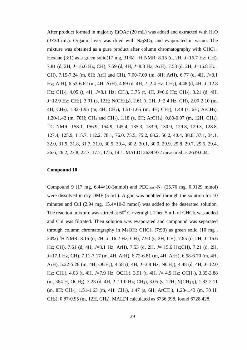
After product formed in majority EtOAc (20 mL) was added and extracted with H2O
(3×30 mL). Organic layer was dried with Na2SO4, and evaporated in vacuo. The
mixture was obtained as a pure product after column chromatography with CHCl3:
Hexane (3:1) as a green solid(17 mg, 31%). 1H NMR: 8.15 (d, 2H, J=16.7 Hz; CH),
7.81 (d, 2H, J=16.6 Hz; CH), 7.59 (d, 4H, J=8.8 Hz; ArH), 7.53 (d, 2H, J=16.8 Hz ;
CH), 7.15-7.24 (m, 6H; ArH and CH), 7.00-7.09 (m, 8H; ArH), 6.77 (d, 4H, J=8.1
Hz; ArH), 6.53-6.62 (m, 4H; ArH), 4.89 (d, 4H, J=2.4 Hz; CH2), 4.48 (d, 4H, J=12.8
Hz; CH2), 4.05 (t, 4H, J=8.1 Hz; CH2), 3.75 (t, 4H, J=6.6 Hz; CH2), 3.21 (d, 4H,
J=12.9 Hz; CH2), 3.01 (s, 12H; N(CH3)2), 2.61 (t, 2H, J=2.4 Hz; CH), 2.00-2.10 (m,
4H; CH2), 1.82-1.95 (m, 4H; CH2), 1.51-1.65 (m, 4H; CH2), 1.48 (s, 6H; ArCH3),
1.20-1.42 (m, 70H; CH3 and CH2), 1.18 (s, 6H; ArCH3), 0.80-0.97 (m, 12H, CH3). 13C NMR :158.1, 156.9, 154.9, 145.4, 135.3, 133.9, 130.9, 129.8, 129.3, 128.8,
127.4, 125.9, 115.7, 112.2, 78.1, 76.0, 75.5, 75.2, 68.2, 56.2, 40.4, 38.8, 37.1, 34.1,
32.0, 31.9, 31.8, 31.7, 31.0, 30.5, 30.4, 30.2, 30.1, 30.0, 29.9, 29.8, 29.7, 29.5, 29.4,
26.6, 26.2, 23.8, 22.7, 17.7, 17.6, 14.1. MALDI 2639.972 measured as 2639.604.
Compound 10
Compound 9 (17 mg, 6.44×10⁻³mmol) and PEG2000-N3 (25.76 mg, 0.0129 mmol)
were dissolved in dry DMF (5 mL). Argon was bubbled through the solution for 10
minutes and CuI (2.94 mg, 15.4×10⁻³ mmol) was added to the deaerated solution.
The reaction mixture was stirred at 600 C overnight. Then 5 mL of CHCl3 was added
and CuI was filtrated. Then solution was evaporated and compound was separated
through column chromatography in MeOH: CHCl3 (7:93) as green solid (10 mg ,
24%) 1H NMR: 8.15 (d, 2H, J=16.2 Hz; CH), 7.90 (s, 2H; CH), 7.85 (d, 2H, J=16.6
Hz; CH), 7.61 (d, 4H, J=8.1 Hz; ArH), 7.53 (d, 2H, J= 15.6 Hz;CH), 7.21 (d, 2H,
J=17.1 Hz, CH), 7.11-7.17 (m, 4H, ArH), 6.72-6.81 (m, 4H, ArH), 6.58-6.70 (m, 4H,
ArH), 5.22-5.28 (m, 4H; OCH2), 4.58 (t, 4H, J=3.8 Hz; NCH2), 4.48 (d, 4H, J=12.0
Hz; CH2), 4.03 (t, 4H, J=7.9 Hz; OCH2), 3.91 (t, 4H, J= 4.9 Hz; OCH2), 3.35-3.88
(m, 364 H, OCH2), 3.23 (d, 4H, J=11.0 Hz; CH2), 3.05 (s, 12H; N(CH3)2), 1.83-2.11
(m, 8H; CH2), 1.51-1.63 (m, 4H; CH2), 1.47 (s, 6H; ArCH3), 1.23-1.43 (m, 70 H;
CH2), 0.87-0.95 (m, 12H, CH3). MALDI calculated as 6736.998, found 6728.428.
39
CHAPTER 4
4 SYNTHESIS OF MODULES FOR A MOLECULAR
DEMULTIPLEXER
4.1 Introduction
The potential application of linking molecular logic gates for diagnosis and
therapeutic purposes is very exciting. As it is reported in de Silva article1 molecules
that can perform like logic gates are seen as prerequisites for the molecular
information processing. Although they have some limitations according to their
inspired precedents, Boolean logic, one of these limitations “input-output
heterogeneity” can create a positive situation that one can design a single molecule
that may perform two different logic gate operations. 76 Demultiplexer is a kind of
logic gate operation that uses this advantage. It is a combinational device that takes
one input and selects between multiple outputs depending upon the control groups.
It is discussed previously that molecular logic operations are now seen as the
backbone of photodynamic therapy where the selectivity is seen as the supreme key
of the theranostics. It is known that a simple logic gate operation, an AND gate, can
enhance the selectivity and brings advantages for the diagnosis. 77 Demultiplexer,
can be very effective in this from this point of view by being a dual selective in
outputs such as light and cytotoxic singlet oxygen. In this thesis we designed the
modules of such molecular demultiplexer that can be used for further researches in
theranostics.
4.2 Design and Synthesis
Design of a molecular logic gate with a proper application is quite hard. It is known
that a demultiplexer can switch between the two outputs with one input and a control
group. In this project we aimed to synthesize the modules of such a molecular
demultiplexer that can diagnose the carcinogenic cells and can apply therapy by
killing the cancer cells via generation of singlet oxygen with the help of emission
property. Our modules are composed of three different parts; first one is the 40
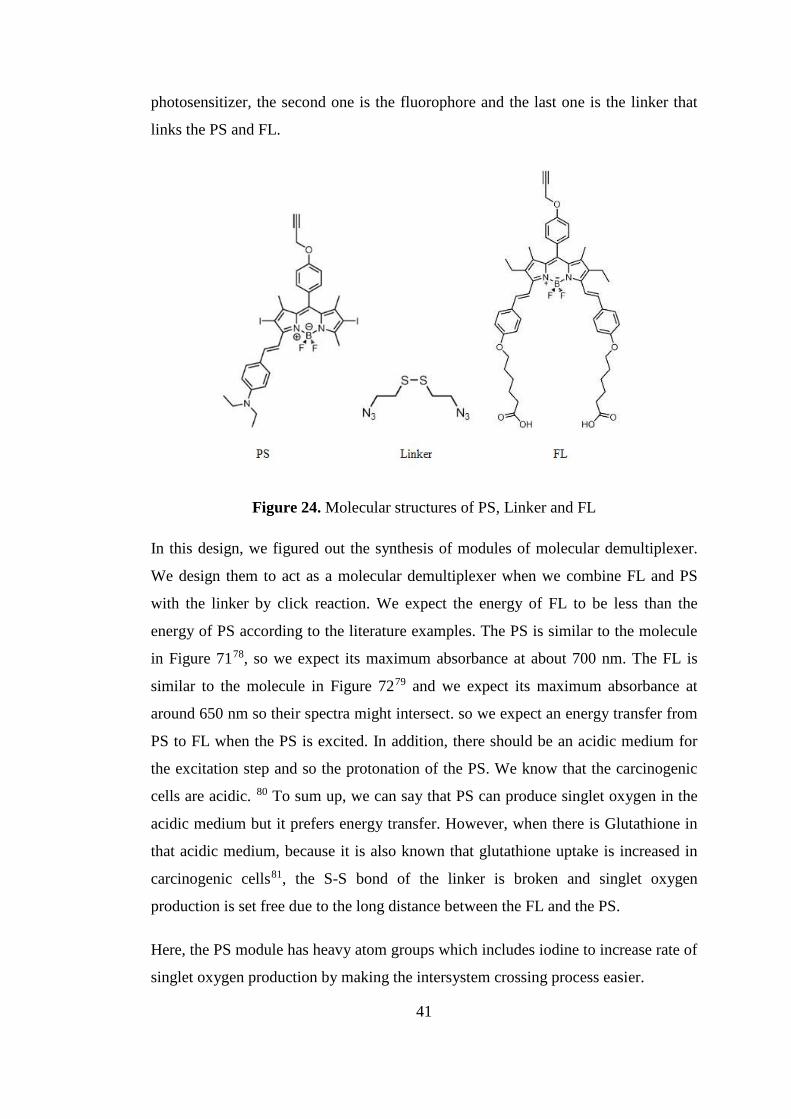
photosensitizer, the second one is the fluorophore and the last one is the linker that
links the PS and FL.
Figure 24. Molecular structures of PS, Linker and FL
In this design, we figured out the synthesis of modules of molecular demultiplexer.
We design them to act as a molecular demultiplexer when we combine FL and PS
with the linker by click reaction. We expect the energy of FL to be less than the
energy of PS according to the literature examples. The PS is similar to the molecule
in Figure 7178, so we expect its maximum absorbance at about 700 nm. The FL is
similar to the molecule in Figure 7279 and we expect its maximum absorbance at
around 650 nm so their spectra might intersect. so we expect an energy transfer from
PS to FL when the PS is excited. In addition, there should be an acidic medium for
the excitation step and so the protonation of the PS. We know that the carcinogenic
cells are acidic. 80 To sum up, we can say that PS can produce singlet oxygen in the
acidic medium but it prefers energy transfer. However, when there is Glutathione in
that acidic medium, because it is also known that glutathione uptake is increased in
carcinogenic cells81, the S-S bond of the linker is broken and singlet oxygen
production is set free due to the long distance between the FL and the PS.
Here, the PS module has heavy atom groups which includes iodine to increase rate of
singlet oxygen production by making the intersystem crossing process easier.
41

Figure 25. Schematic synthesis of PS
We first synthesized the propargyl aldehyde (compound 11) from 4-
Hydroxybenzaldehyde and propargyl bromide, and then used it for the simple
BODIPY reaction (compound 12) with 2,4-Dimethylpyrrole. After iodination
reaction of the BODIPY (compound 13), Knoevenagel condensation reaction was
used with 4-Diethylaminobenzaldehyde and the targeted PS (compound 14) was
obtained as it is seen in Figure 25.
The FL module is designed to be fluorescent. We used pre-synthesized propargyl
aldehyde and 2,4-dimethyl-3-ethyl pyrrole to synthesize the BODIPY (compound
15). Then we synthesized the compound 16 by using 4-hydroxybenzaldeyde and 6-
bromohexanoic acid. After that we used these two compounds to synthesize the FL
module (compound 17) by Knoevenagel condensation reaction as it seen in Figure
26.
13
14
11 12
42
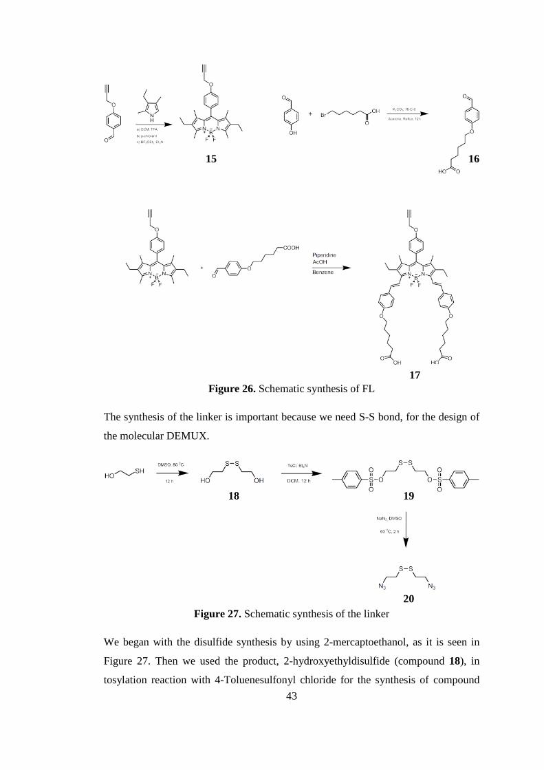
Figure 26. Schematic synthesis of FL
The synthesis of the linker is important because we need S-S bond, for the design of
the molecular DEMUX.
Figure 27. Schematic synthesis of the linker
We began with the disulfide synthesis by using 2-mercaptoethanol, as it is seen in
Figure 27. Then we used the product, 2-hydroxyethyldisulfide (compound 18), in
tosylation reaction with 4-Toluenesulfonyl chloride for the synthesis of compound
15 16
17
18 19
20
43

19. And finally, we made an azide synthesis (compound 20) from this compound by
using sodium azide.
4.3 Results and Discussion
In this project we designed and synthesized the necessary modules for the concept of
molecular demultiplexer. As it is mentioned before, molecular logic gates have
opened a new door to the exciting research areas. In addition when they are
integrated with the life necessity such as diagnosis and therapy of some cancer types
imputed as undeterred diseases it becomes an attractive field to discover.
Photodynamic therapy is such a sort of therapy that can easily be combined with
logic gate approach. However, it is a serious application for diseased people so it
might be controlled in a detailed way. Molecular demultiplexer is one of the unique
molecular logic gate. It is unique because it has an ability to select between the two
different outputs when it receives an input. It should define the diseased region of the
tissue and then select the right patway of the outputs to operate.
Photodynamic therapy based on the excitation of the specialized photosensitizer that
is in the tumor tissue and then generation of the singlet oxygen to destroy
aforementioned tissue. It can be seen that molecular DEMUX can be a very effective
way in the photodynamic therapy context. It can be designed to select between the
two outputs such as energy transfer or the generation of singlet oxygen.
In this project, we expect the energy of the FL be less than the energy of the PS. In a
molecular DEMUX, one can combine FL and PS with a linker such that we
synthesized here. If one excites the molecule in a normal tissue, there will be no
change in the molecule. If one excites the PS in an acidic medium at a certain
wavelenght, energy transfer is expected from PS to FL and there is no harm for the
tissue. If there is GSH in that acidic medium than the molecule prefers to generate
singlet oxygen because the breakage of the S-S bond causes FL and PS to be
seperated and energy transfer becomes impossible because of the distance between
them. It can be seen clearly in Figure 28.
44

Figure 28 Logic gate function of the DEMUX
Synthesis of these compounds are important for the application of logic gates in real
life. As it is mentioned before our design composed of three important modules; PS,
linker and FL. In the synthesis of PS, it is important that it has heavy atoms like
iodine because it is known that Bodipys become more efficient photosensitizers with
the incorporation of heavy atoms. As it is implied heavy atom substituted Bodipys
have intersystem crossing step faster which then causes generation of singlet oxygen.
In addition one can adjust the absorption band of a Bodipy. Tunable absorption band
is an important phenomenon for a PDT agent. Absorption peak of the module can be
tuned in between 550-800 nm wavelenght with the substitution of styryl groups to
the Bodipy core because the ligth that can be used for PDT should be in this range.
The NMR spectra show that the compound was synthesized successfully.
Our second target compound was the linker. As it is mentioned before the S-S bond
system was designed according to the gluthathione’s structure. A simple azide
synthesis procedure was applied to get the compound. Mass data and NMR spectra
indicate that the synthesis of the linker was accomplished.
The synthesis of FL was the most arduous part of the project. Because there are two
carboxylic acid groups on the molecule, applying column chromatography was
difficult. However, the synthesis was completed assuring the target compound was 45

yielded. NMR spectrum and mass spectrum verify the final compound was the target
compound.
4.4 Conclusion
In this Project we made progress with the idea that includes design and synthesis of
a possible molecular logic gate; DEMUX as a theranostic device. Our design is
composed of a three different modules; a photosensitizer that is able to generate
singlet oxygen upon excitation with the help of the heavy atom substitution, a
fluorophore that is fluorescent especially upon protonation and linker that is able to
link these two modules to each other and is able to break up in the presence of GSH.
In conclusion we can say that although we faced a lot of difficulties in the
purification steps of the modules we are able synthesize these three PDT modules in
a successful manner. Our mass spectra and NMR spectra support the synthesis is
successful. We expect our modules to be used can be used as we envisoned in the
synthesis of a functional threnostic device based on a molcular demultiplexer. This
in turn will be a radical departure from the current approaches for obtaining
theranostic agents, with hopefully much better results.
4.5 Experimental Details
4.5.1 Methods and Materials
Chemicals for the all experiments were purchased from Merck and Sigma-Aldrich
and used without further purification. 1H NMR and 13C NMR spectra were recorded
on Bruker DPX-400 in CDCl3 where the internal standard is tetramethylsilane. s
(singlet), d (doublet), t (triplet), q (quartet), dd (doublet of doublet) and m (multiplet)
are used for the indication of splitting pattern. Reactions are monitored by thin layer
chromatography using Merck TLC Silica gel 60 F254. Merck Silica Gel 60 (particle
size: 0.040-0.063 mm, 230-400 mesh ASTM) was used for the column
chromatography. Mass spectroscopy was performed on Agilent Technologies 6530
Accurate-Mass Q-TOF LC/MS.
46
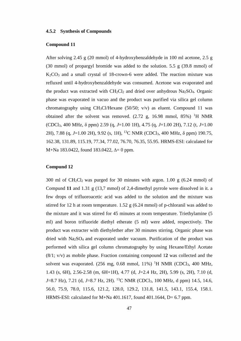
4.5.2 Synthesis of Compounds
Compound 11
After solving 2.45 g (20 mmol) of 4-hydroxybenzaldehyde in 100 ml acetone, 2.5 g
(30 mmol) of propargyl bromide was added to the solution. 5.5 g (39.8 mmol) of
K2CO3 and a small crystal of 18-crown-6 were added. The reaction mixture was
refluxed until 4-hydroxybenzaldehyde was consumed. Acetone was evaporated and
the product was extracted with CH2Cl2 and dried over anhydrous Na2SO4. Organic
phase was evaporated in vacuo and the product was purified via silica gel column
chromatography using CH3Cl/Hexane (50/50; v/v) as eluent. Compound 11 was
obtained after the solvent was removed. (2.72 g, 16.98 mmol, 85%) 1H NMR
(CDCl3, 400 MHz, δ ppm) 2.59 (q, J=1.00 1H), 4.75 (q, J=1.00 2H), 7.12 (t, J=1.00
2H), 7.88 (q, J=1.00 2H), 9.92 (s, 1H), 13C NMR (CDCl3, 400 MHz, δ ppm) 190.75,
162.38, 131.89, 115.19, 77.34, 77.02, 76.70, 76.35, 55.95. HRMS-ESI: calculated for
M+Na 183.0422, found 183.0422, ∆= 0 ppm.
Compund 12
300 ml of CH2Cl2 was purged for 30 minutes with argon. 1.00 g (6.24 mmol) of
Compund 11 and 1.31 g (13,7 mmol) of 2,4-dimethyl pyrrole were dissolved in it. a
few drops of trifluoroacetic acid was added to the solution and the mixture was
stirred for 12 h at room temperature. 1.52 g (6.24 mmol) of p-chloranil was added to
the mixture and it was stirred for 45 minutes at room temperature. Triethylamine (5
ml) and boron trifluoride diethyl etherate (5 ml) were added, respectively. The
product was extracter with diethylether after 30 minutes stirring. Organic phase was
dried with Na2SO4 and evaporated under vacuum. Purification of the product was
performed with silica gel column chromatography by using Hexane/Ethyl Acetate
(8/1; v/v) as mobile phase. Fraction containing compound 12 was collected and the
solvent was evaporated. (256 mg, 0.68 mmol, 11%) 1H NMR (CDCl3, 400 MHz,
1.43 (s, 6H), 2.56-2.58 (m, 6H+1H), 4.77 (d, J=2.4 Hz, 2H), 5.99 (s, 2H), 7.10 (d,
J=8.7 Hz), 7.21 (d, J=8.7 Hz, 2H). 13C NMR (CDCl3, 100 MHz, d ppm) 14.5, 14.6,
56.0, 75.9, 78.0, 115.6, 121.2, 128.0, 129.2, 131.8, 141.5, 143.1, 155.4, 158.1.
HRMS-ESI: calculated for M+Na 401.1617, found 401.1644, D= 6.7 ppm.
47

Compund 13
0.256 g (0.677 mmol) of compound 12 was dissolved in 100 ml ethanol. 0.429 g
(1.692 mmol) of I2 was added to the solution. 0.238 g (1.354 mmol) of HIO3 was
dissolved in a few drops of water and added to the previous mixture. The reaction
mixture was stirred at 60 0C and monitored with TLC. When all BODIPY was
consumed 50 ml of saturated solution of sodiumthiosulfate was added and stirred for
an extra 30 minutes. Extraction was performed with DCM. The purification of the
product was done with column chromatography by using Hexane/DCM (50/50 ;v/v)
as eluent. The product was obtained through the evaporation of the organic solvent.
(0.382 g, 0.607 mmol, 90%) 1H NMR (CDCl3, 400 MHz, δ ppm) 1.36 (s, 6H), 2.49
(s, 1H), 2.56 (s, 6H), 4.70 (s, 2H), 7.04 (d, J=8.8 Hz, 2H), 7.09 (d, J=8.8 Hz, 2H). 13C NMR (CDCl3, 400 MHz, δ ppm) 16.0, 17.1, 56.1, 76.1, 85.8, 100.1, 116.0,
127.8, 129.1, 131.6, 141.4, 146.0, 156.7, 158.6. HRMS-ESI: calculated for M+Na
652.9550, found 652.9515, ∆= 5.4 ppm.
Compound 14
0.200 g (0.317 mmol) of compound 13 and 0.050 g (0.285 mmol) of 4-
diethylaminobenzaldehyde were dissolved in 30 ml benzene. 0.45 ml of piperidine
and 0.45 ml of acetic acid were added. The reaction mixture was refluxed by using
Dean-Stark. Extraction was done with DCM and water. The organic layer was dried
with sodium sulfate and its solvent was evaporated under vacuum. The product was
purified by column chromatography where the mobile phase was DCM/Hexane (2/1;
v/v). Fraction containing compound 14 was collected and the solvent was
evaporated. (0.045 g, 57 µmol, 18%) 1H NMR (CDCl3, 400 MHz, δ ppm) 1.24 (m,
Hz, 6H), 1.51 (s, 3H), 2.60 (t, J=10.8, 3H), 3.44 (m, 4H), 4.79 (d, J=2.4, 2H), 6.69
(d, J=8.9, 2H), 7.15 (m, 2H), 7.48 (s, 2H), 7.54 (t, J=8.8, 3H), 8.22 (d, J=16.5, 1H) 13C NMR (CDCl3, 400 MHz, δ ppm) 158.83, 140.84, 129.81, 129.54, 115.90,
113.36, 111.60, 76.00, 56.21, 44.56, 29.74, 17.88, 16.96, 16.25, 12.77 HRMS (TOF-
ESI): m/z calcd for C33H32BF2I2N3O- 787.0666 [M-H]-, found: 787.06594 [M-H], Δ
= -0.84 ppm.
Compound 15
48

1.5 g (9.36 mmol) of compound 11 was dissolved in 300 ml DCM to which Argon
was purged for 30 min. 2.78 ml (2.54 g, 20.60 mmol) of 2,4-dimethyl-3-ethyl pyrrole
was added to the solution. 3 drops of trifluoroacetic acid was added dropwise. The
reaction mixture was stirred for 12 h at room temperature. Then 2.31 g (9.36 mmol)
of p-chloranil was added and the mixture was stirred for 45 min. After that 8 ml of
triethyl amine and 8 ml of boron trifluoride diethyl etherate were added, in sequence.
The reaction mixture was stirred for an extra 30 min. Then it was extracted with
water. The organic phase was dried over Na2SO4 and evaporated. Silica gel column
chromatography was applied to the product by using Hexane/EtOAc solvent system
(8/1; v/v). The fraction that contains compound 15 was collected and its solvent was
evaporated under vacuum. (0.6 g, 1.38 mmol, 15%) 1H NMR (CDCl3, 400 MHz,
δ ppm) 7.22 (m, 2H), 7.10 (t, J = 0.02 Hz, 2H), 4.78 (d, J = 2.40 Hz, 2H), 2.55 (m,
5H), 2.32 (t, J=7.49, 5H), 1.60 (s, 5H), 1.28 (s, 3H) 1.00 (t, J= 0.01, 3H). 13C NMR
(CDCl3, 400 MHz, δ ppm) 158.0, 153.6, 140.0, 138.4, 132.8, 131.1, 129.8, 128.9,
115.6, 78.1, 75.8, 56.0, 17.1, 14.6, 12.5, 11.8.
Compound 16
1 g (8.19 mmol) of 4-Hydroxybenzaldehyde and 1.36 g (6.96 mmol) of 6-
Bromohexanoic acid were dissolved in 150 ml acetone. A few crystals of 18-Crown-
6 was added to the mixture. Then 3.40 g (24.57 mmol) of K2CO3 was added. The
reaction mixture was refluxed for 12 h and then filtered. The filtrate was dissolved in
water and then neutralized with 4 M HCl. White precipitate was filtered and dried. 1H NMR (400 MHz, DMSO) 1.56 (q, J=2.00 2H), 1.75 (q, J=2.00, 2H), 2.24 (t,
J=2.00, 2H), 2.50 (m, 2H), 4.08 (t, J=2.00, 2H), 7.12 (t, J=1.00, 2H), 7.86 (q,
J=1.00, 2H), 9.86 (s, 1H), 11.92 (s, 1H), 13C NMR (CDCl3, 400 MHz, δ ppm)
191.75, 174.89, 164.14, 132.28, 115.37, 68.40, 40.59, 40.39, 40.18, 39.97, 39.76,
39.56, 39.34, 34.06, 28.69, 25.51, 24.68 HRMS (TOF-ESI): m/z calcd for C13H16O4-
235.0961 [M-H]-, found: 235.09758 [M-H]-, Δ = 6.26 ppm.
Compound 17
0.10 g (0.24 mmol) of compound 15 was dissolved in 30 ml of benzene. 0.13 g (0.60
mmol) of compound 16 was added to the solution. Then 0.3 ml of acetic acid and 0.3
49

ml of piperidine were added. The reaction mixture was refluxed for 2 h with Dean-
Stark apparatus. It was extracted with DCM and water. After the solvent of organic
phase was removed silica gel column chromatography was applied for purification
with Methanol/EtOAc (1/9; v/v). The fraction containing the product was evaporated
under vacuum. (0.027 g, 0.032 mmol, 13%). 1H NMR (400 MHz, DMSO) 1.10 (q,
J=8.44, 4H), 1.34 (d, J=7.02, 4H), 1.45 (d, J=7.48, 6H), 1.56 (s, 4H), 1.72 (s, 6H),
2.25 (s, 4H), 4.02 (s, 4H), 4.39 (t, J=6.08, 4H), 4.46 (s, 1H), 4.89 (d, J=2.47, 2H),
7.01 (t, J=8.91, 4H), 7.07 (d, J=8.60, 2H), 7.17 (d, J=8.88, 2H), 7.31 (d, J=8.89, 2H),
7.53 (d, J=8.82, 2H), 7.68 (s, 2H), 7.89 (d, J=11.02, 2H), 12.06 (s, 2H), HRMS
(TOF-ESI): m/z calcd for C52H57BF2N2O7- 868.4191 [M-H]-, found: 868.41904 [M-
H]-, Δ = -0.11 ppm.
Compound 18
2 g (25.6 mmol) of mercapto ethanol was dissolved in 10 ml DMSO. The mixture
was stirred at 80 0C for 12 hours. After cooling the mixture to room temperature
extraction was performed with brine and ethyl acetate. Organic layer was dried with
sodium sulfate and after evaporation silica gel column chromatography was applied
with Hexane/Ethyl Acetate (3/1; v/v) as eluent. Solvent of the fraction that contain
compound 5 was removed and product was obtained. (1.79 g, 11.6 mmol, 45%) 1H
NMR (CDCl3, 400 MHz, δ ppm) 3.90 (t, 4H, J = 5.84 Hz; OCH2), 7.30 (t, 4H, J =
5.88 Hz; SCH2). 13C NMR (CDCl3, 400 MHz, δ ppm) 60.4, 41.3.
Compound 19
1 g (6.48 mmol) of compound 18 was dissolved in DCM/Et3N solvent system (10/1;
v/v). As the solution was being cooled with ice bath 1.22 g (12,96 mmol) of p-
toluene sulfonyl chloride was dissolved in 10 ml DCM and added dropwise to the
solution. The mixture was stirred for 12 h. Extraction was done with DCM and
water. Organic phase was dried with sodium sulphate and evaporated. Silica gel
column chromatography was applied with CHCl3 as eluent. Fraction that contained
product was evaporated and a white solid was obtained. (2.82 g, 6.1 mmol, 94%) 1H
NMR (CDCl3, 400 MHz, δ ppm) 7.83 (d, 4H, J = 8.04 Hz; ArH), 7.38 (d, 4H, J =
7.93 Hz; ArH), 4.21 (t, 4H, J = 6.61 Hz; OCH2), 2.85 (t, 4H, J = 6.53 Hz; SCH2),
50

2.48 (s, 6H, ArCH3). 13C NMR (CDCl3, 400 MHz, δ ppm) 145.2, 130.0, 128.0, 67.5,
36.9, 21.7. HRMS (TOF-ESI): m/z calcd for C18H22NaO6S4+ 485.0191 [M+Na]+,
found: 485.0104 [M+Na]+, Δ = 17.94 ppm.
Compound 20
1 g (2.16 mmol) of compound 19 was dissolved in 10 ml DMSO. Then 0.648 g of
(9.98 mmol) sodium azide was added to the solution. The reaction mixture was
stirred at 60 0C for 2 hours. Extraction was done with ethyl acetate and water after
cooling the reaction mixture to room temperature. Organic layer was dried with
Na2SO4 and evaporated under vacuum. The yellow oily product was obtained. (0.42
g, 2.05 mmol, 95%) 1H NMR (CDCl3, 400 MHz, δ ppm) 3.63 (t, 4H, J = 6.76 Hz;
NCH2), 2.89 (t, 4H, J = 6.76 Hz; SCH2). 13C NMR (CDCl3, 400 MHz, δ ppm) 49.9,
37.6.
51

CHAPTER 5
5 CONCLUSION
In this thesis we focused on the two different projects. The first project was the
design and synthesis of a PEGylated Calix[4]arene as a carrier for a Bodipy that is
substituted by heavy atoms and has complementary water soluble units. It is obvious
that calix[4]arene molecule can be functionalized with two Bodipy units having a
high tendency to intersystem crossing property due to heavy iodine atoms. Some
hydrophobic character was gained due the long alkyl chains on the lower rim of the
calixarene. There are two PEG groups that adds hydrophilic character which then
make the compound amphiphilic. The styryl group make long wavelength absorption
ensured.. In the second project, we designed and synthesized the modules of
molecular logic gate, DEMUX. There are three main compounds for this kind of
molecular logic gates geared for theranostic potential, these are, photosensitizer,
fluorophore and a analyte responsive linker between them. The synthesis part was
completed successfully. It will be a significant progress for future work.
To conclude, we can say that PDT is a promising area for scientists and when it is
coupled with logic gate concepts, the potetial for information processing therapeutic
agents is enormous.
52

BIBLIOGRAPHY
[1] A. P. De Silva, N. H. Q. Gunaratte and C. P. McCoy, “A molecular photoionic AND gate based on fluorescent signalling” Nature, vol. 364, pp. 42-44, 1993. [2] A. Urruticoechea, R. Alemani, J. Balart, A. Villanueva, F. Vinals, and G. Capella, PubMed, vol. 16, no. 1, pp. 3-10, 2010. [3] A. Gorman, J. Killoran, C. O’Shea, T. Kenna, W. M. Gallagher and D. F. O’Shea, “In Vitro Demonstration of the Heavy-Atom Effect for Photodynamic Therapy” J.Am. Chem. Soc., vol. 126, pp. 10619–10631, 2004. [4 ] I. Roy, T. Y. Ohulchanskyy, H. E. Pudavar, E. J. Bergey, A. R. Oseroff, J. Morgan T. J. Dougherty and P. N. Prasad, “Ceramic-based nanoparticles entrapping water-insoluble photosensitizing anticancer drugs: a novel drug-carrier system for photodynamic therapy,” J. Am. Chem. Soc., vol. 125, pp. 7860- 7865, 2003. [5] B. Wardle, “Principles and Applications of Photochemistry,” Wiley, pp. 33, 2009. [6] B. R. Henry, W. Siebrand, “Spin–Orbit Coupling in Aromatic Hydrocarbons. Analysis of Nonradiative Transitions between Singlet and Triplet States in Benzene and Naphthalene”, J. Chem. Phys. vol. 54, No. 3, pp. 1072-1085, 1971. [7] K. Szacilowski, W. Macyk, A. Drzewiecka Matuszek, M. Brindell, G. Stochel, “Bioinorganic photochemistry: frontiers and mechanisms” Chem. Rev. vol. 105, no. 6, pp. 2647-2694, 2005. [8] J. C. Cosiar, D. O. Cowan, “Photochemical Heavy-Atom Effects”, Acc. Chem. Res. vol. 11, no. 9, pp. 334-341, 1978. [9] M. Colombo, M. W. George, J. N. Moore, D. I. Pattison, R. N. Perutz, I. G. Virrels, T. Q. Ye, “Ultrafast reductive elimination of hydrogen from a metal carbonyl dihydride complex; a study by time-resolved IR and visible spectroscopy” Dalton Trans., pp.2857-2859, 1997.
53

[10] M. Kasha, “Discussions of the Faraday Society”, The Faraday Society, vol. 9, pp. 14-19, 1950. [11] J. R. Lalowicz, “Principles of Fluorescence Spectroscopy” 3rd Edition, Springer, pp. 6, 2006. [12] M. R. Wasielewski, “Photoinduced Electron Transfer in Supramolecular Systems for Artificial Photosynthesis”, Chem. Rev., vol. 92, pp. 435-461, 1992. [13] A. P. de Silva, H. Q. Gunaratne, T. Gunnlaugsson, A. .J. Huxley, C. P. McCoy, J. T. Rademacher, T. E. Rice, “Signaling Recognition Events with Fluorescent Sensors and Switches”, Chem. Rev., vol.97, no.5, pp. 1515-1566, 1997. [14] V. Balzani, A. Credi, M. Venturi, “Molecular Devices and Machines”, Nanotoday, vol. 2, no. 2, 2007. [15] A. P. De Silva, B. McCauhan, B. O. F. McKinney and M. Querol, “Newer optical-based molecular devices from older coordination chemistry”, Dalton Trans., pp. 1902-1913, 2003. [16] A. P. de Silva, S. A. de Silva, “Fluorescent signalling crown ethers; ‘switching on’ of fluorescence by alkali metal ion recognition and binding in situ”, J. Chem. Soc., Chem. Commun., pp.1709-1710, 1986. [17] A. P. de Silva, R. A. D. D. Rupasinghe, “A new class of fluorescent pH indicators based on photo-induced electron transfer” J. Chem. Soc., Chem. Commun., Issue. 23, pp. 1649-1740, 1985. [18] B. Valeur, F. Badaoui, E. Bardez, J. Bourson, P. Boutin, A. Chatelain, I. Devol, B. Larrey, J. P. Lefe`vre, A. Soulet, Eds. J. P. Desvergne, A. W. Czarnik, “Chemosensors of Ion and Molecule Recognition”, NATO ASI Series, Vol. 492, pp. 195-196, 1997. [19] B. Valeur, I. Leray, “Design principles of fluorescent molecular sensors for cation recognition” Coord. Chem. Rev., Issue. 1, vol. 205, pp.3-40, 2000.
54

[20] R. E. Gawley, H. Mao, M. M. Haque, J. B. Thorne, J. S. Pharr, “Visible fluorescence chemosensor for saxitoxin” J. Org. Chem. vol. 72, no. 6, pp.2187-2191, 2007. [21] E. Deniz, G. C. Isbasar, O. A. Bozdemir, L. T. Yildirim, A. Siemiarczuk, E. U. Akkaya, “Bidirectional switching of near IR emitting boradiazaindacene fluorophores” Org. Lett., vol. 10, Issue. 16, pp. 3401-3403, 2008. [22] V. Balzani, A. Credi, M. Venturi, “Molecular Devices and Machines – A Journey into the Nano World”, Wiley-VCH, 2002. [23] N. J. Turro, “Modern Molecular Photochemistry”, University Science Books, Sausalito, 1991. [24] M. D. Yilmaz, O. A. Bozdemir, E. U. Akkaya, “Light harvesting and efficient energy transfer in a boron-dipyrrin (BODIPY) functionalized perylenediimide derivative”Org. Lett., vol. 8, Issue. 13, pp.2871-2873, 2006. [25] D. L. Dexter, “A Theory of Sensitized Luminescence in Solids” J. Chem. Phys., vol. 21, Issue. 5, pp. 836-850, 1953. [26] S. Prathapan, T. E. Johnson, J. S. Lindsey, “Building-Block Synthesis of Porphyrin Light-Harvesting Arrays” J. Am. Chem. Soc., vol. 115, pp.7519-7520, 1993. [27] A. Loudet, K. Burgess, “BODIPY dyes and their derivatives: syntheses and spectroscopic properties” Chem. Rev. Vol. 107, Issue. 11, pp. 4891-4932, 2007. [28] T.G. Kim, J.C. Castro, A. Loudet, J.G.S. Jiao, M.R. Topp, R.M. Hochstrasser, K. Burgess, M.R. Topp, “Correlations of structure and rates of energy transfer for through-bond energy-transfer cassettes” J. Phys. Chem. A., vol. 110, pp. 20-27, 2006. [29] T. Förster, “Zwischenmolekulare Energiewanderung und Fluoreszenz” Annalen der Physik, vol. 437, Issue. 1-2, pp. 55-75, 1948. [30] T. Förster, “Experimentelle und theoretische Untersuchung des zwischenmolecularen Uebergangs von Electronenanregungsenergie” Z. Naturforsch, vol. 4, pp.321-327, 1949.
55

[31] T. Förster, “Transfer Mechanisms of Electronic Excitation”, Discussions Faraday Soc., vol. 27, Issue. 7, 1959. [32] B. Valeur, “Molecular Fluorescence: Principles and Applications”, Wiley-WC, 2002. [33] J. R. Lakowicz, Principles of Fluorescence Spectroscopy, Kluwer Acadamic, Plenum Publishers, 1999. [34] A. Sharma, S. G. Schulman, Introduction to Fluorescence Spectroscopy, Wiley Science, 1999. [35] G. Barin, M. D. Yilmaz, E. U. Akkaya, “Boradiazaindacene (Bodipy)-based building blocks for the construction of energy transfer cassettes” Tet. Lett., vol. 50, pp. 1738-1740, 2009. [36] T. L. Floyd, Digital Fundamentals, Prentice-Hall International Inc., Upper Saddle River, NJ, 1997. [37] A. Saba, N. Manna, Digital Principles & Logic Design, Infinity Science Press, London, 2007. [38] S. Gibilisco, The Illustrated Dictionary of Electronics, McGraw-Hill, New York, 2001. [39] J. Millman, A. Grabel, Microelectronics, McGraw-Hill, London, 1988. [40] Szacilowski, “Digital information processing in molecular systems” Chem. Rev., vol. 108, pp. 3481-3548, 2008. [41] N. Hush, “Molecular electronics: Cool computing” Nature Materials, vol.2, pp. 134-135, 2003. [42] P. Siffert, E. Krimmel, Silicon: Evolution and Future of a Technology, Springer, Berlin, 2004.
56

[43] V. Bojinov, N. Georgiov, Molecular Asensors and Molecular Logic Gates (Review), Journal of the University Chemical Technology and Metallurgy, vol. 46, no. 1, pp.3-26, 2011. [44] J.F. Callan, A.P. de Silva and N.D. McClenaghan, “Switching between Molecular Switch Types by Module Rearrangement: Ca2+-enabled, H+-driven ‘Off-On-Off’, H+-driven YES and PASS 0 as well as H+, Ca2+-driven AND Logic Operations”, Chem. Commun., vol. 18, pp. 2048-2049, 2004. [45] K. Szacilowski, “Digital Information Processing in Molecular Systems” Chem. Rew., vol. 108, pp. 3481-3548, 2008. [46] K. Szacilowski, W. Macyk, “Working prototype of an optoelectronic XOR/OR/YES reconfigurable logic device based on nanocrystalline semiconductors ” Solid-State Electron, Vol. 50, Issues 9-10, pp.1649-1655, 2006. [47] E. Perez-Inestrota, J-M. Montenegro, D. Collado, R. Suau, “A Molecular 1:2 Demultiplexer”, Chem. Commun., pp. 1085-1087, 2008. [48] M. Triesscheijn, P. Baas, J. H. M. Schellens, F. A. Stewart, “Photodynamic Therapy in Oncology” The Oncologist, vol. 11, pp. 1034- 1044, 2006. [49] S. Miyamoto, G. E. Ronsein, F. M. Prado, M. Uemi, T. C. Correa, I. N. Toma, A. Bertolucci, M. C. B. Oliveira, F. D. Motta, M. H. G. Medeiros, “Biological hydroperoxides and singlet molecular oxygen generation” IUBMB Life, vol. 59, pp. 322-331, 2007. [50] D. E. Dolmans, D. Fukumura, R. K. Jain, “Photodynamic Therapy for Cancer”, Nat. Rev. Cancer, vol. 3, pp.380-387, 2003. [51] A. P. Castano, P. Mroz, M. R. Hamblin, “Photodynamic therapy and anti-tumour immunity” Nat. Rev. Cancer, vol. 6, pp. 535-545, 2006.
57

[52] K. Szaciowski, W. Macyk, A. Drzewiecka-Matuszek, M. Brindell, G. Stochel, “Bioinorganic photochemistry: frontiers and mechanisms”, Chem. Rev. Vol. 105, pp. 2647-2694, 2005. [53] O. Z. Raab, “Ueber die wirking fluoreszierender stoffe auf infusorien” Zeitschrift fuer Biologie, vol. 39, pp.524-526, 1900. [54] H. von Trappeiner, A. Jesionek, “Therapeutische Versuche mit fluoreszierenden Stoffen” Med Worchenschr, vol. 47 pp. 2042-2044, 1903. [55] J. Moan, E. Wold, “Detection of singlet oxygen production by ESR” Nature, vol. 279, pp. 450-451, 1979. [56] R. Ritz, “Visualization and Photodynamic Therapy in Malignant Glioma - An Overview and Perspectives, Advances in the Biology, Imaging and Therapies for Glioblastoma, Prof. Clark Chen (Ed.), pp. 183, 2011. [57] T. J. Dougherty, J. E. Kaufman, A. Goldfarb, K. R. Weishaupt, D. Boyle, A. Mittleman, “Photoradiation therapy for the treatment of malignant tumors” Cancer Res., vol. 38, pp. 2628-2635, 1978. [58] J. R. Lacowicz, “Principles of Fluorescence Spectroscopy”, Springer, 2nd Ed. Kluwer/Plenum, New York, 1999. [59] B. W. Henderson, T. J. Dougherty, “How does photodynamic therapy work?” Photochem. Photobiol., vol. 55, pp. 145-157, 1992. [60] A. Wright, C. Hawkins, M. Davies, “Photo-oxidation of cells generates long-lived intracellular protein peroxides” Free radical biology & medicine. Vol. 34 pp. 637-647, 2003. [61] J. Cadet, P. Di Mascio, “Peroxides in Biological Systems” John Wiley and Sons Ltd, Chichester., pp. 915-999, 2006.
58
[62] N. L. Oleinick, R. L. Morris, I. Belichenko, “The role of apoptosis in response to photodynamic therapy: what, where, why, and how. “ Photochem. Photobiol. Sci., vol. 1, pp. 1-21, 2002. [63] B. Alberts, A. Johnson, J. Lewis et al. “Molecular Biology of the Cell”, 4th edition, New York: Garland Science; 2002. [64] N. J. Turro, “In Modern Molecular Photochemistry; University Science Books” Sausalito, CA, pp. 191-195, 1991. [65] A. Gorman, J. Killoran, C. O’Shea, T. Kenna, W. M. Gallagher, D. F. O’Shea, “In vitro demonstration of the heavy-atom effect for photodynamic therapy.”J. Am. Chem. Soc., pp. 10619–10631, vol. 126, 2004. [66] A. Graczykowa “Photodynamic method of diagnosis and therapy of tumors (in Polish); Dom Wydawniczy Bellona” Warszawa, 1999. [67] L. Huang, X. R. Yu, W. H. Wu, J. Z. Zhao, “Styryl Bodipy-C60 Dyads as Efficient Heavy-Atom-Free Organic Triplet Photosensitizers” Org. Lett., vol. 14, pp. 2594-2597, 2012. [68] Y. Cakmak, S.Kolemen, S. Duman, Y. Dede, Y. Dolen, B. Kilic, Z. K ostereli, L. T. Yildirim, A. L. Dogan, D. Guc, E. U. Akkaya, “Designing Excited States: Theory Guided Access to Efficient Photosensitizers for Photodynamic Action” Angew. Chem. Int. Edit. Vol. 50, pp. 11937-11941, 2011. [69] M. Ethijaran, Y. H. Chen, P. Joshi, R. K. Pandey, “The Role of the Porphyrin Chemistry in Tumor Imaging and Photodynamic Therapy” Chem. Soc. Rev. Vol. 40, pp. 340-362, 2011. [70] Z. Kostereli, T. Ozdemir, O. Buyukcakir, E. U. Akkaya, “Tetrastyryl-BODIPY Based Dendritic Light Harvester and Estimation of Energy Transfer Efficiency” Org. Lett. Vol. 14, pp. 3636-3639, 2012. [71] C. N. Baki, E. U. Akkaya, “Boradiazaindacene-appended calix[4]arene: Fluorescence sensingof pH near neutrality” J. Org. Chem., vol.66, pp.1512-1513, 2001.
59

[72] Y. Cakmak, T. Nalbantoglu, T. Durgut, E. U. Akkaya, “PEGylated calix[4]arene as a carrier for a Bodipy-based photosensitizer”, Tetrahedron Letters, Vol. 55, Issue. 2, pp. 538-540, 2014. [73] S. Erbas, A. Gorgulu, M. Kocakusakogullari, E. U. Akkaya, Noncovalent Functionalized SWNTs as Delivery Agents for Novel Bodipy Based Potential PDT Sensitizers”, Chem. Commun., Vol. 33, pp. 4956-4958, 2009. [74] G. R. Martinez, F. Garcia, L. H. Catalani, J. Cadet, M. C. B. Oliveira, G. E. Ronsein, S. Miyarnoto, M. H. G. Medeiros, P. di Mascio, “Synthesis of a Hydrophilic and non-ionic Anthracene Derivative, the N,N’-di-(2,3-dihydroxypropyl)-9,10-anthracenedipropanamide As a Chemical Trap for Singlet Molecular Oxygen Detection in Biological Systems” Tetrahedron, Vol. 62, pp. 10762-10770, 2006. [75] O. J. Dalbavie, J. B. Regnouf-De-Vains, R. Lamartine, S. Lecocq, M. Perrin, “Complexation of Cobalt(II) At The Upper Rim of Two New calix[4]arene/bipyridine-based Podands” Eur. J. Inorg. Chem., Vol. 4, pp. 683-691, 2000. [76] O. A. Bozdemir, R. Guliyev, O. Buyukcakir, S. Selcuk, S. Kolemen, G. Gulseren, T. Nalbantoglu, H. Boyaci, E. U. Akkaya, “Selective Manipulation of ICT and PET Processes in Styryl-Bodipy Derivatives: Applications in Molecular Logic and Fluorescence Sensing of Metal Ions” J. Am. Chem. Soc., Vol. 132, p.p. 8029-8036, 2010. [77] S. Ozlem, E. U. Akkaya, “Thinking Outside the Silicon Box: Molecular AND Logic As an Additional Layer of Selectivity in Singlet Oxygen Generation for Photodynamic Therapy” J. Am. Chem. Soc., Vol. 131, p.p. 48-49, 2009. [78] A. Kamkaew, S. H. Lim, H. B. Lee, L. V. Kiew, L. Y. Chunq, K. Burgess, “BODIPY Dyes in photodyamic therapy”Chem. Soc. Rew. Vol. 42, pp.78-78, 2013.
[79] Z. Kostereli, T. Ozdemir, O. Buyukcakir, E. U. Akkaya, “Tetrastyryl-BODIPY-Based Dendritic Light Harverster and Estimation of Energy Transfer Efficiency” Org. Lett. Vol. 14, pp.3636-3639, 2012.
60

[80] A. Thiry, J.-M. Dogne, B. Maereel, C. T. Supuran, “Targeting tumor-associated carbonic anhydrase IX in cancer therapy” Trends Pharmacol. Vol.11, pp.566-573, 2006. [81] L. Chaiswing, T. D. Oberley, “Extracellular/Microenvironmental Redox State” Antioxid. Redox Sign. Vol. 13, pp. 449-465, 2010.
61

APPENDIX
A.1 PEGylated Calix[4]arene as a Carrier for a Bodipy-based
Photosensitizer
A.1.1 1H NMR and 13C NMR Spectra
Figure 29. 1H NMR of Compound 5 (Copyright ©, 2014, Elsevier. Reprinted with
permission from Ref. 72)
62

Figure 30. 13C NMR of Compound 5 (Copyright ©, 2014, Elsevier. Reprinted with
permission from Ref. 72)
Figure 31. 1H NMR of Compound 6 (Copyright ©, 2014, Elsevier. Reprinted with
permission from Ref. 72)
63
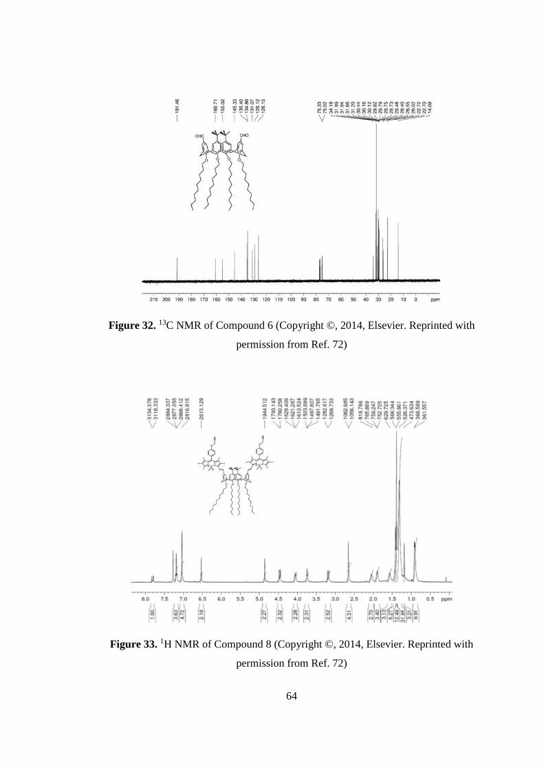
Figure 32. 13C NMR of Compound 6 (Copyright ©, 2014, Elsevier. Reprinted with
permission from Ref. 72)
Figure 33. 1H NMR of Compound 8 (Copyright ©, 2014, Elsevier. Reprinted with
permission from Ref. 72)
64

Figure 34. 13C NMR of Compound 8 (Copyright ©, 2014, Elsevier. Reprinted with
permission from Ref. 72)
Figure 35. 1H NMR of Compound 9 (Copyright ©, 2014, Elsevier. Reprinted with
permission from Ref. 72)
65

Figure 36. Aromatic part of the 1H NMR of Compound 9 (Copyright ©, 2014,
Elsevier. Reprinted with permission from Ref. 72)
Figure 37. Aliphatic part of the 1H NMR of Compound 9 (Copyright ©, 2014,
Elsevier. Reprinted with permission from Ref. 72)
66

Figure 38. Detailed aliphatic part of the 1H NMR of Compound 9 (Copyright ©,
2014, Elsevier. Reprinted with permission from Ref. 72)
Figure 39. 13C NMR of Compound 9 (Copyright ©, 2014, Elsevier. Reprinted with
permission from Ref. 72)
67

Figure 40.1H NMR of Compound 10 (Copyright ©, 2014, Elsevier. Reprinted with
permission from Ref. 72)
Figure 41.Aromatic part of the 1H NMR of Compound 10 (Copyright ©, 2014,
Elsevier. Reprinted with permission from Ref. 72)
68
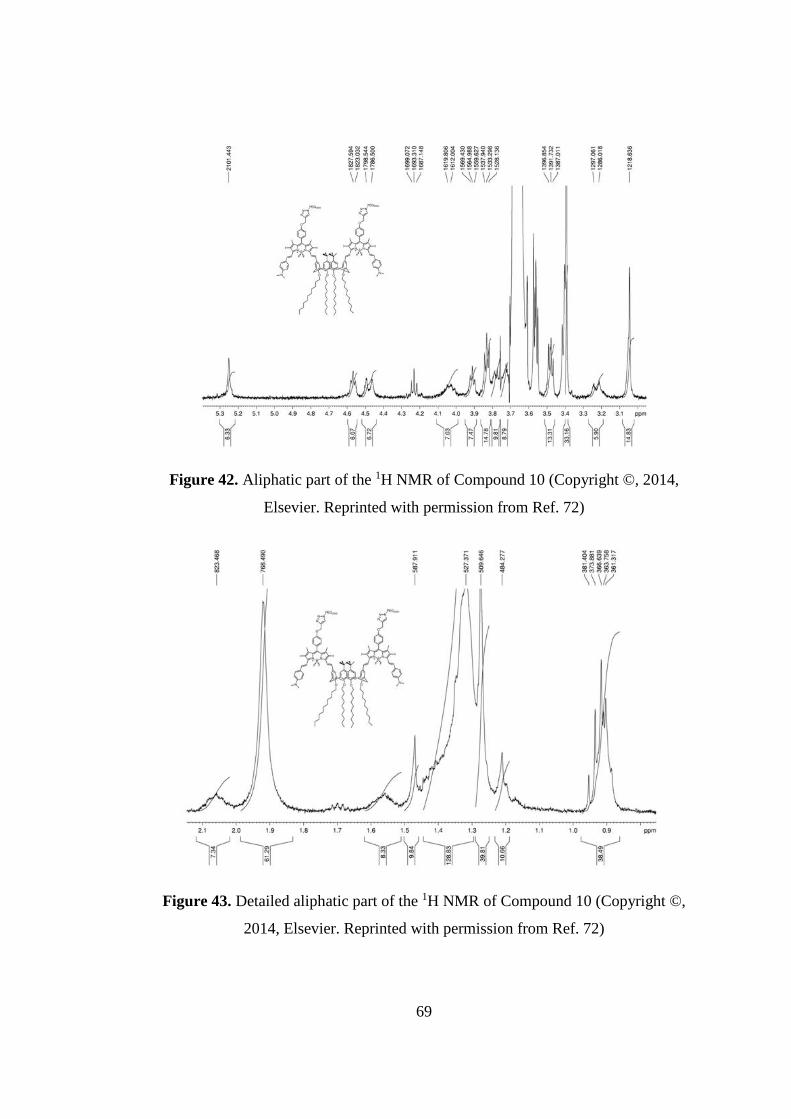
Figure 42. Aliphatic part of the 1H NMR of Compound 10 (Copyright ©, 2014,
Elsevier. Reprinted with permission from Ref. 72)
Figure 43. Detailed aliphatic part of the 1H NMR of Compound 10 (Copyright ©,
2014, Elsevier. Reprinted with permission from Ref. 72)
69

A.1.2 MASS Spectra
Figure 44. MALDI Spectrum of compound 5 (Copyright ©, 2014, Elsevier.
Reprinted with permission from Ref. 72)
Figure 45. MALDI Spectrum of compound 6 (Copyright ©, 2014, Elsevier.
Reprinted with permission from Ref. 72)
70
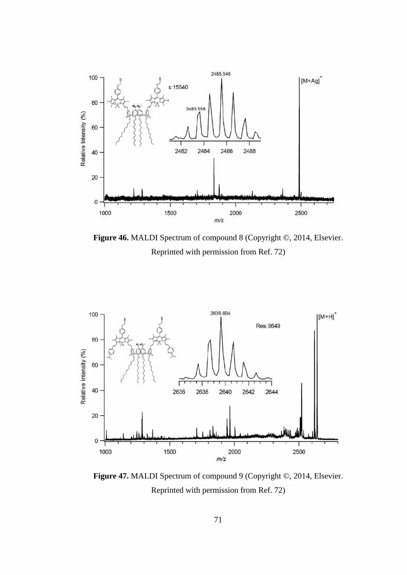
Figure 46. MALDI Spectrum of compound 8 (Copyright ©, 2014, Elsevier.
Reprinted with permission from Ref. 72)
Figure 47. MALDI Spectrum of compound 9 (Copyright ©, 2014, Elsevier.
Reprinted with permission from Ref. 72)
71

Figure 48. MALDI Spectrum of compound 10 (Copyright ©, 2014, Elsevier.
Reprinted with permission from Ref. 72)
Figure 49. Detailed MALDI Spectrum of compound 10 (Copyright ©, 2014,
Elsevier. Reprinted with permission from Ref. 72)
72

A.2 Synthesis of Molecular Demultiplexer Modules
A.2.1 1H NMR and 13C NMR Spectra
Figure 50. 1H NMR of Compound 11
73

Figure 51. 13C NMR of Compound 11
Figure 52. 1H NMR of Compound 12
74

Figure 53. 13C NMR of Compound 12
Figure 54. 1H NMR of Compound 13
75
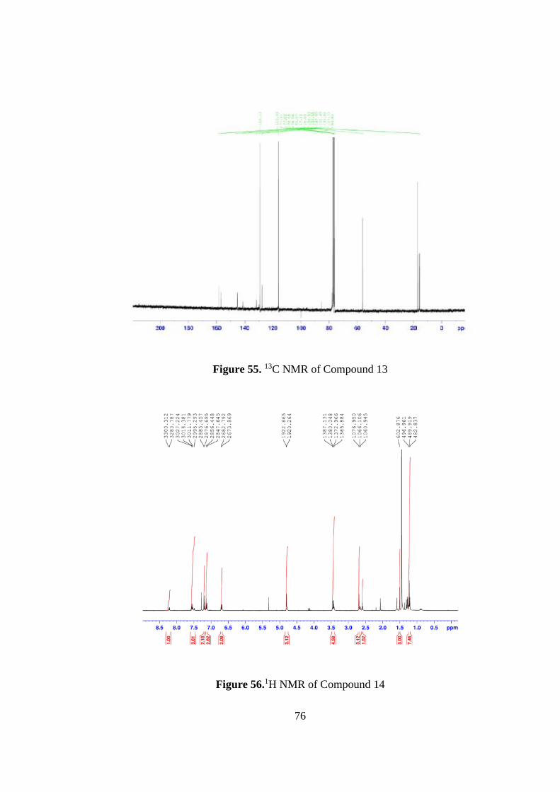
Figure 55. 13C NMR of Compound 13
Figure 56.1H NMR of Compound 14
76
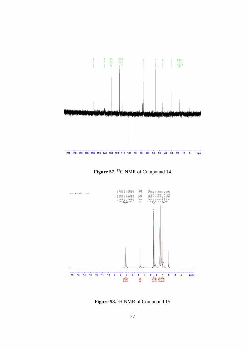
Figure 57. 13C NMR of Compound 14
Figure 58. 1H NMR of Compound 15
77

Figure 59. 13C NMR of Compound 15
Figure 60. 1H NMR of Compound 16
78

Figure 61.13C NMR of Compound 16
Figure 62. 1H NMR of Compound 17
79

Figure 63. 1H NMR of Compound 18
Figure 64. 13C NMR of Compound 18
80

Figure 65. 1H NMR of Compound 19
Figure 66. 1H NMR of Compound 20
81
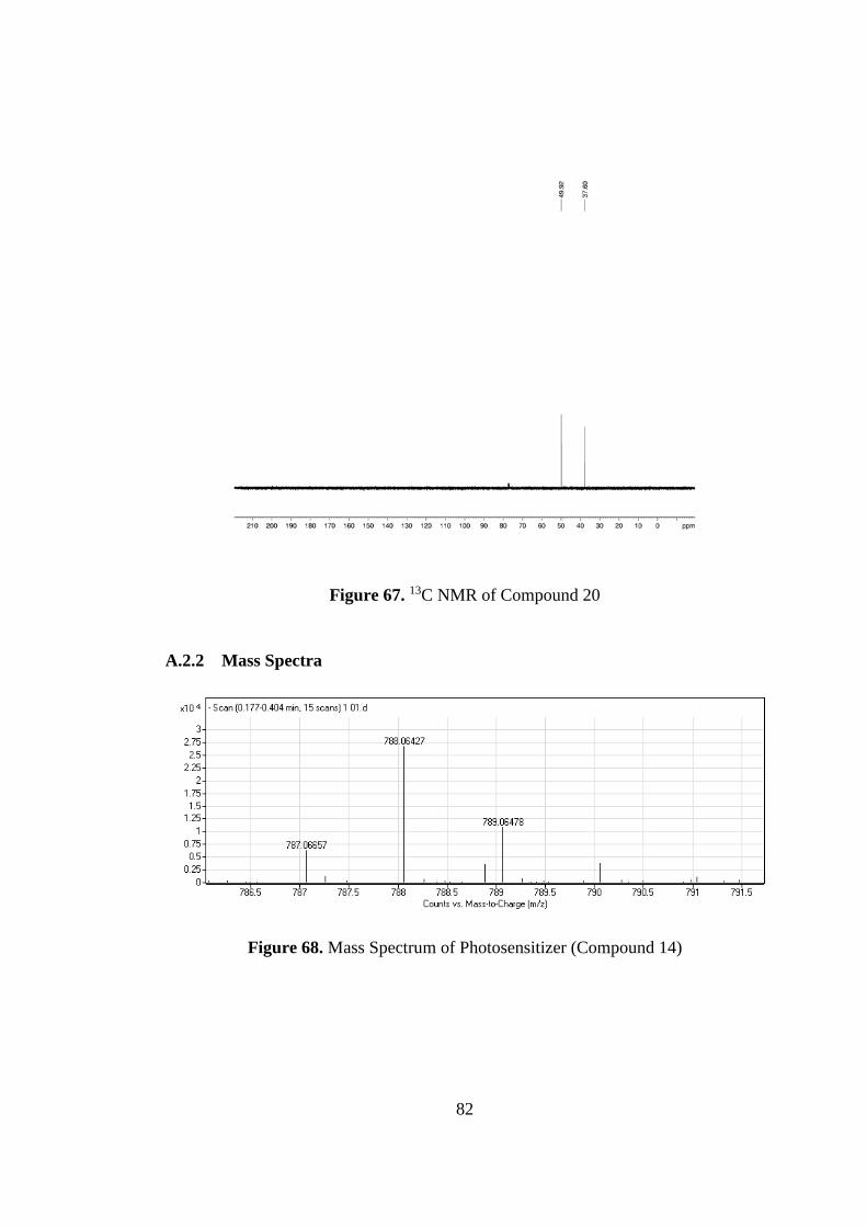
Figure 67. 13C NMR of Compound 20
A.2.2 Mass Spectra
Figure 68. Mass Spectrum of Photosensitizer (Compound 14)
82
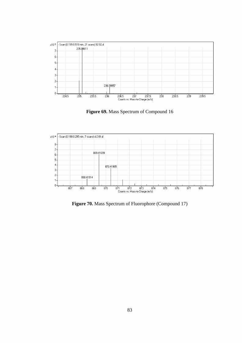
Figure 69. Mass Spectrum of Compound 16
Figure 70. Mass Spectrum of Fluorophore (Compound 17)
83
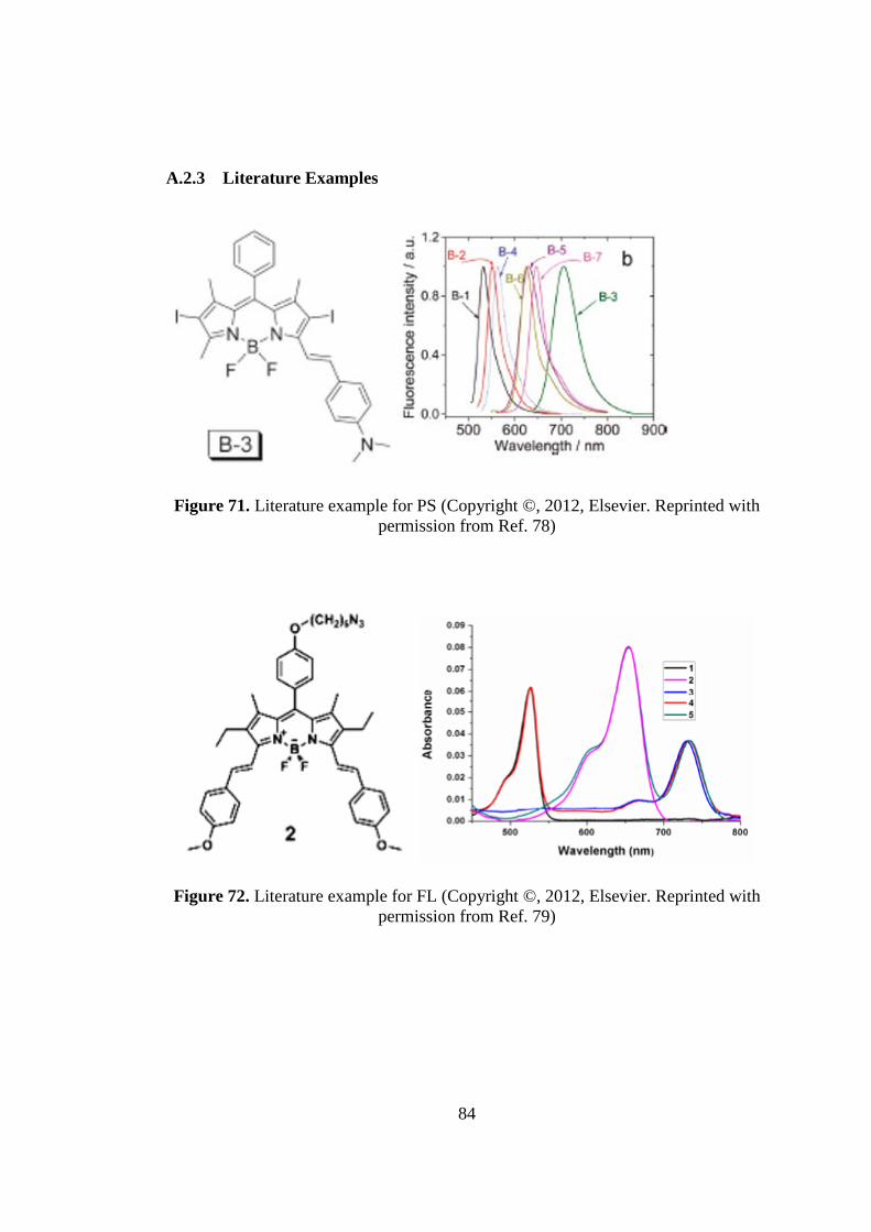
A.2.3 Literature Examples
Figure 71. Literature example for PS (Copyright ©, 2012, Elsevier. Reprinted with permission from Ref. 78)
Figure 72. Literature example for FL (Copyright ©, 2012, Elsevier. Reprinted with permission from Ref. 79)
84