Embed Size (px)
Citation preview

CAPE CANAVERAL AIR FORCE STATION, LAUNCH COMPLEX 39, HAER No. FL-8-11-B VEHICLE ASSEMBLY BUILDING (John F. Kennedy Space Center) VAB Road, East of Kennedy Parkway North Cape Canaveral Brevard County Florida
PHOTOGRAPHS
WRITTEN HISTORICAL AND DESCRIPTIVE DATA
Historic American Engineering Record National Park Service
Southeast Region Department of the Interior
Atlanta, GA 30303

HISTORIC AMERICAN ENGINEERING RECORD
CAPE CANAVERAL AIR FORCE STATION, LAUNCH COMPLEX 39, VEHICLE ASSEMBLY BUILDING (John F. Kennedy Space Center)
HAER No. FL-8-11-B Location: VAB Road, east of Kennedy Parkway North John F. Kennedy Space Center Cape Canaveral Brevard County Florida U.S.G.S. 7.5. minute Orsino, Florida, quadrangle, Universal Transverse Mercator coordinates: 17.534100.3161940 Date of Construction: 1962-1966; 1976 (modifications for Space Shuttle Program) Architect: URSAM (Max Urbahn [architectural]; Roberts and Schaefer [structural];
Seelye, Stevenson, Value and Knecht [civil, mechanical and electrical]; and Moran, Proctor, Mueser and Rutledge [foundations]), New York
Builder: The foundation and flooring were built by the Blount Brothers Corp.,
Birmingham, Alabama; steel framework by American Bridge Division of U.S. Steel, Atlanta; and building construction by the firms of Morrison-Knudsen Co., Inc., Perini Corp., and Paul Hardeman, Inc., all of California. Modifications by Frank Briscoe Company, Inc., East Orange, New Jersey.
Present Owner: National Aeronautics and Space Administration (NASA) Kennedy Space Center, FL 32899-0001 Present Use: Aerospace Facility-vehicle integration and check-out Significance: The Vehicle Assembly Building (VAB) was listed in the National Register
of Historic Places (NRHP) on January 21, 2000. It is considered significant under NRHP Criterion A in the area of Space Exploration, and under NRHP Criterion C in the area of Engineering. Because the VAB has achieved significance within the past 50 years, Criteria Consideration G applies. Originally nominated in the context of the Apollo Program, ca. 1961 through 1975, the VAB has since gained importance in the context of the Space Shuttle Program, ca. 1969 to 2010. The period of significance for the VAB is from 1980, when the first Space Shuttle vehicle was assembled, through 2010, the designated end of the Space Shuttle Program. The Space Shuttle Program is the longest running

CAPE CANAVERAL AIR FORCE STATION, LAUNCH COMPLEX 39, VEHICLE ASSEMBLY BUILDING (John F. Kennedy Space Center) HAER No. FL-8-11-B Page 2
American space program to date. Unlike the Mercury, Gemini and Apollo programs, the emphasis was on cost effectiveness and reusability, as well as the construction of a space station. The VAB is a unique facility, which supports the integration and stacking of the complete Space Shuttle vehicle on the Mobile Launcher Platform (MLP). Under Criterion C, the VAB contains four large high bays; two of which contain a platform system designed for the size of the Space Shuttle vehicle, and two that contain platforms shaped around the external tank (ET). Each system contains a combination of stationary and moveable platforms, set at various levels, which provide access to specific components. In addition, the VAB is one of the world’s largest buildings by volume at 129,428,000 cubic feet. The VAB is of exceptional importance to the Space Shuttle Program, and because it is less than 50 years in age, Criteria Consideration G applies.
Report Prepared Patricia Slovinac, Architectural Historian by: Archaeological Consultants, Inc. 8110 Blaikie Court, Suite A Sarasota, Florida 34240 Date: July 2009

CAPE CANAVERAL AIR FORCE STATION, LAUNCH COMPLEX 39, VEHICLE ASSEMBLY BUILDING (John F. Kennedy Space Center) HAER No. FL-8-11-B Page 3
HISTORICAL INFORMATION NASA’s John F. Kennedy Space Center (KSC) The John F. Kennedy Space Center is National Aeronautics and Space Administration’s (NASA) primary Center for launch and landing operations, vehicle processing and assembly, and related programs in support of manned space missions. It is located on the east coast of Florida, about 150 miles south of Jacksonville, and to the north and west of Cape Canaveral, in Brevard and Volusia Counties, and encompasses almost 140,000 acres. The Atlantic Ocean and Cape Canaveral Air Force Station (CCAFS) are located to the east, and the Indian River is to the west. Following the launch of Sputnik I and Sputnik II, which placed Soviet satellites into Earth’s orbit in 1957, the attention of the American public turned to space exploration. President Dwight D. Eisenhower initially assigned responsibility for the U.S. Space Program to the Department of Defense (DoD). The Development Operations Division of the Army Ballistic Missile Agency (ABMA), led by Dr. Wernher von Braun, began to focus on the use of missiles to propel payloads, or even a man, into space. The United States successfully entered the space race with the launch of the Army’s scientific satellite Explorer I on January 31, 1958 using a modified Jupiter missile named Juno I .1 With the realization that the military’s involvement in the space program could jeopardize the use of space for peaceful purposes, President Eisenhower established the NASA on October 1, 1958 as a civilian agency with the mission of carrying out scientific aeronautical and space exploration, both manned and unmanned. Initially working with NASA as part of a cooperative agreement, President Eisenhower officially transferred to NASA a large portion of the Army’s Development Operations Division, including the group of scientists led by Dr. Werner von Braun, and the Saturn rocket program.2 NASA became a resident of Cape Canaveral in 1958 when the Army Missile Firing Laboratory (MFL), then working on the Saturn rocket project under the direction of Kurt Debus, was transferred to the agency. Several Army facilities at CCAFS were given to NASA, including various offices and hangars, as well as Launch Complexes (LC) 5, 6, 26, and 34. The MFL was renamed Launch Operations Directorate (LOD) and became a branch office of Marshall Space Flight Center (MSFC). As LOD responsibilities grew, NASA granted the launch team increased status by making it a field center called the Launch Operations Center (LOC), and separating it from MSFC.
1 Charles D. Benson and William B. Faherty. Gateway to the Moon. Building the Kennedy Space Center Launch Complex. (Gainesville, University Press of Florida, 2001), 1-2. 2 Benson and Faherty, 15.

CAPE CANAVERAL AIR FORCE STATION, LAUNCH COMPLEX 39, VEHICLE ASSEMBLY BUILDING (John F. Kennedy Space Center) HAER No. FL-8-11-B Page 4
In May 1961, President John F. Kennedy charged NASA and the associated industries to develop a space program that would surpass the Soviet program by landing a man on the moon by the end of the decade. With the new, more powerful Saturn V rocket and the stepped-up launch schedule, it was apparent that a new launch complex was required, and CCAFS, with twenty-two launch complexes, did not have the space for new rocket facilities. Merritt Island, an undeveloped area west and north of the Cape, was selected for acquisition, and in 1961 the Merritt Island Launch Area (MILA, which, with the LOC would become KSC) was born. In that year, NASA requested from Congress authority to purchase 80,000 acres of property, which was formally granted in 1962. The U.S. Army Corps of Engineers (ACOE) acted as agent for purchasing land, which took place between 1962 and 1964. NASA began gaining title to the land in late 1962, taking over 83,903.9 acres by outright purchase, which included several small towns, such as Orsino, Wilson, Heath and Audubon, many farms, citrus groves, and several fish camps. Negotiations with the State of Florida provided submerged lands, resulting in the acquisition of property identified on the original Deed of Dedication. Much of the State-provided land was located south of the Old Haulover Canal and north of the Barge Canal. The American program to put a man in space and land on the Moon proceeded rapidly with widespread support. In November 1963, the LOC and MILA were renamed John F. Kennedy Space Center to honor the late President.3 The space program was organized into three phases: Mercury, Gemini, and Apollo. Project Mercury, initiated in 1958, was executed in less than five years. Begun in 1964, Project Gemini was the intermediate step toward achieving a manned lunar landing, bridging the gap between the short-duration Mercury flights and the long-duration missions proposed for the Apollo Program.4
Apollo, the largest and most ambitious of the manned space programs, had as its goal the landing of astronauts on the moon and their safe return to Earth. Providing the muscle to launch the spacecraft was the Saturn family of heavy vehicles. Saturn IB rockets were used to launch the early unmanned Apollo test flights and the first manned flight, Apollo 7, which carried astronauts on a ten-day earth orbital mission.5 Three different launch vehicles were used in Apollo: Saturn I, Saturn IB and Saturn V; and three different launch complexes were involved: LC 34 and LC 37 on CCAFS, and LC 39 on KSC (only LC 39 is still active). Altogether, thirty-two Saturn flights occurred (seven from LC 34, eight from LC 37, and seventeen from LC 39, including Skylab and the Apollo-Soyuz Test Project) during the Apollo era. Of the total thirty-two, fifteen were manned, and of the seven attempted lunar landing missions, six were successful. No major launch vehicle failures of either
3 Harry A Butowsky. Reconnaissance Survey: Man in Space. (Washington, D.C.: National Park Service, 1981), 5; Benson and Faherty, 146. 4 Butowsky, 5. 5 Butowsky, 5.

CAPE CANAVERAL AIR FORCE STATION, LAUNCH COMPLEX 39, VEHICLE ASSEMBLY BUILDING (John F. Kennedy Space Center) HAER No. FL-8-11-B Page 5
Saturn IB or Saturn V occurred. There were two major command/service module (CSM) failures, one on the ground (Apollo 1) and one on the way to the Moon (Apollo 13).6 The unmanned Apollo 4 mission, which lifted off on November 9, 1967, was the first Saturn V launch and the first launch from LC 39 at KSC. On July 21, 1969, the goal of landing a man on the moon was achieved when Apollo 11 astronauts Armstrong, Aldrin, and Collins successfully executed history’s first lunar landing. Armstrong and Aldrin walked on the surface of the moon for twenty-two hours and collected twenty-one kilograms of lunar material. Apollo 17 served as the first night launch in December 1972. An estimated 500,000 people saw the liftoff which was the final launch of the Apollo Program.7 Skylab, an application of the Apollo Program, served as an early type of space station. With 12,700 cubic feet of work and living space, it was the largest habitable structure ever placed in orbit, at the time. The station achieved several objectives: scientific investigations in Earth orbit (astronomical, space physics, and biological experiments); applications in Earth orbit (earth resources surveys); and long-duration spaceflight. Skylab 1 orbital workshop was inhabited in succession by three crews launched in modified Apollo CSMs (Skylab 2, 3 and 4). Actively used until February 1974, Skylab 1 remained in orbit until July 11, 1979, when it re-entered Earth’s atmosphere over the Indian Ocean and Western Australia after completing 34,181 orbits.8 The Apollo-Soyuz Test Project (ASTP) of July 1975, the final application of the Apollo Program, marked the first international rendezvous and docking in space, and was the first major cooperation between the only two nations engaged in manned space flight. As the first meeting of two manned spacecraft of different nations in space, first docking, and first visits by astronauts and cosmonauts into the others’ spacecraft, the ASTP was highly significant. The ASTP established workable joint docking mechanisms, taking the first steps toward mutual rescue capability of both Russian and American manned missions in space.9 On January 5, 1972, President Nixon delivered a speech in which he outlined the end of the Apollo era and the future of a reusable space flight vehicle, the Space Shuttle, which would provide “routine access to space.” By commencing work at this time, Nixon added, “we can have the Shuttle in manned flight by 1978, and operational a short time after that.”10 The Space Task Group (STG), previously established by President Nixon in February 1969 to recommend a future course for the U.S. Space Program, presented three choices of long-range space plans. All
6 National Aeronautics and Space Administration (NASA). Facts: John F. Kennedy Space Center. (1994), 82. 7 NASA, Facts, 86-90. 8 NASA, Facts, 91. 9 NASA, Facts, 96. 10 Marcus Lindroos. “President Nixon’s 1972 Announcement on the Space Shuttle.” (NASA Office of Policy and Plans, NASA History Office, updated April 14, 2000).

CAPE CANAVERAL AIR FORCE STATION, LAUNCH COMPLEX 39, VEHICLE ASSEMBLY BUILDING (John F. Kennedy Space Center) HAER No. FL-8-11-B Page 6
included an Earth–orbiting space station, a space shuttle, and a manned Mars expedition.11 Although none of the original programs presented was eventually selected, NASA implemented a program, shaped by the politics and economic realities of its time, that served as a first step toward any future plans for implementing a space station.12 On January 5, 1972, President Richard Nixon instructed NASA to proceed with the design and building of a partially reusable space shuttle consisting of a reusable orbiter, three reusable main engines, two reusable solid rocket boosters (SRBs), and one non-reusable external liquid fuel tank (ET). NASA’s administrators vowed that the shuttle would fly at least fifty times a year, making space travel economical and safe. NASA gave responsibility for developing the shuttle orbiter vehicle and overall management of the Space Shuttle Program (SSP) to the Manned Spacecraft Center (MSC; now Johnson Space Center [JSC]) in Houston, based on the Center’s experience. MSFC in Huntsville, Alabama was responsible for development of the Space Shuttle Main Engine (SSME), SRBs, the ET, and for all propulsion-related tasks. Engineering design support continued at MSC, MSFC and NASA’s Langley Research Center (LaRC), in Virginia, and engine tests were to be performed at NASA’s Mississippi National Space Technology Laboratories (NSTL, later named Stennis Space Center [SSC]) and at the Air Force’s Rocket Propulsion Laboratory in California, which later became the Santa Susana Field Laboratory (SSFL).13 NASA selected KSC as the primary launch and landing site for the SSP. KSC, responsible for designing the launch and recovery facilities, was to develop methods for shuttle assembly, checkout, and launch operations.14 On September 17, 1976, the full-scale Orbiter Vehicle (OV) prototype Enterprise (OV- 101) was completed. Designed for test purposes only and never intended for space flight, structural assembly of this orbiter had started more than two years earlier in June 1974 at Air Force Plant (AFP) 42 in Palmdale, California. Although the Enterprise was an aluminum shell prototype incapable of space flight, it reflected the overall design of the orbiter. As such, it served successfully in 1977 as the test article during the Approach and Landing Tests (ALT) aimed at checking out both the mating with the Boeing 747 Shuttle Carrier Aircraft (SCA) for ferry operations, as well as the orbiter’s unpowered landing capabilities. The first orbiter intended for space flight, Columbia (OV-102), arrived at KSC from the shuttle assembly facility in Palmdale, California in March 1979. Originally scheduled to lift off in late 11 National Aeronautics and Space Administration (NASA), History Office, NASA Headquarters. “Report of the Space Task Group, 1969.” 12 Dennis R. Jenkins. Space Shuttle, The History of the National Space Transportation System. The First 100 Missions. (Cape Canaveral, Florida: Specialty Press, 2001), 99. 13 Jenkins, 122. 14 Linda Neuman Ezell. NASA Historical Databook Volume III Programs and Projects 1969-1978. The NASA History Series, NASA SP-4012, (Washington, D.C.: NASA History Office, 1988), Table 2-57; Ray A. Williamson. “Developing the Space Shuttle.” Exploring the Unknown: Selected Documents in the History of the U.S. Civil Space Program, Volume IV: Accessing Space. (Edited by John M. Logsdon. Washington, D.C.: U.S. Printing Office, 1999), 172-174.

CAPE CANAVERAL AIR FORCE STATION, LAUNCH COMPLEX 39, VEHICLE ASSEMBLY BUILDING (John F. Kennedy Space Center) HAER No. FL-8-11-B Page 7
1979, the launch date was delayed by problems with both the SSME components as well as the thermal protection system (TPS). Columbia spent 610 days in the Orbiter Processing Facility (OPF), another thirty-five days in the Vehicle Assembly Building (VAB) and 105 days on Pad 39A before finally lifting off on April 12, 1981. STS-1, the first orbital test flight and first Space Shuttle Program mission, ended with a landing on April 14 at Edwards Air Force Base (AFB) in California. This launch demonstrated Columbia’s ability to fly into orbit, conduct on-orbit operations, and return safely.15 Columbia flew three additional test flights in 1981 and 1982, all with a crew of two. The Orbital Test Flight Program ended in July 1982 with 95 percent of its objectives completed. After the end of the fourth mission, President Ronald Reagan declared that with the next flight the Shuttle would be “fully operational.” A total of 122 Space Shuttle missions have been launched from the KSC between April 1981 and March 2008. From April 1981 until the Challenger accident in January 1986, between two and nine missions were flown yearly, with an average of four to five per year. The milestone year was 1985, when nine flights were successfully completed. The years between 1992 and 1997 were the most productive, with seven or eight yearly missions. Since 1995, in addition to its unique responsibility as the shuttle launch site, KSC also became the preferred landing site. Over the past two decades, the SSP has launched a number of planetary and astronomy missions including the HST, the Galileo probe to Jupiter, Magellan to Venus, and the Upper Atmospheric Research Satellite. In addition to astronomy and military satellites, a series of Spacelab research missions were flown which carried dozens of international experiments in disciplines ranging from materials science to plant biology. Spacelab was a manned, reusable, microgravity laboratory flown into space in the rear of the Space Shuttle cargo bay. It was developed on a modular basis allowing assembly in a dozen arrangements depending on the specific mission requirements.16 The first Spacelab mission, carried aboard Columbia (STS-9), began on November 28, 1983. Four Spacelab missions were flown between 1983 and 1985. Following a hiatus in the aftermath of the Challenger disaster, the next Spacelab mission was not launched until 1990. In total, twenty-four Space Shuttle missions carried Spacelab hardware before the program was decommissioned in 1998.17 In addition to astronomical, atmospheric, microgravity, and life sciences missions, Spacelab was also used as a supply carrier to the HST and the Soviet space station Mir. In 1995, a joint U.S./Russian Shuttle-Mir Program was initiated as a precursor to construction of the International Space Station (ISS). Mir was launched in February 1986 and remained in orbit
15 Jenkins, 268. 16 National Aeronautics and Space Administration (NASA). NASA Shuttle Reference Manual. (1988). 17 STS-90, which landed on May 3, 1998, was the final Spacelab mission. National Aeronautics and Space Administration (NASA). “Shuttle Payloads and Related Information.” KSC Factoids. Revised November 18, 2002.

CAPE CANAVERAL AIR FORCE STATION, LAUNCH COMPLEX 39, VEHICLE ASSEMBLY BUILDING (John F. Kennedy Space Center) HAER No. FL-8-11-B Page 8
until March 2001.18 The first approach and flyaround of Mir took place on February 3, 1995 (STS-63); the first Mir docking was in June 1995 (STS-71). During the three-year Shuttle-Mir Program (June 27, 1995 to June 2, 1998) the Space Shuttle docked with Mir nine times. All but the last two of these docking missions used the Orbiter Atlantis. In 1995, Dr. Norman Thagard was the first American to live aboard the Russian space station. Over the next three years, six more U.S. astronauts served tours on Mir. The Shuttle served as a means of transporting supplies, equipment and water to the space station in addition to performing a variety of other mission tasks, many of which involved earth science experiments. It returned to Earth experiment results and unneeded equipment. The Shuttle-Mir program served to acclimate the astronauts to living and working in space. Many of the activities carried out were types they would perform on the ISS.19 On December 4, 1999, Endeavour (STS-88) launched the first component of the ISS into orbit. As noted by Williamson, this event marked, “at long last the start of the Shuttle’s use for which it was primarily designed – transport to and from a permanently inhabited orbital space station.”20 STS-96, launched on May 27, 1999, marked the first mission to dock with the ISS. Since that time, most Space Shuttle missions have supported the continued assembly of the space station. As currently planned, ISS assembly missions will continue through the life of the Space Shuttle Program. The SSP suffered two major setbacks with the tragic losses of the Challenger and Columbia on January 28, 1986 and February 1, 2003, respectively. Following the Challenger accident, the SSP was suspended, and President Ronald Reagan formed a thirteen-member commission to identify the cause of the disaster. The Rogers Commission report, issued on June 6, 1986, which also included a review of the SSP, concluded “that the drive to declare the Shuttle operational had put enormous pressures on the system and stretched its resources to the limit.”21 In addition to mechanical failure, the Commission noted a number of NASA management failures that contributed to the catastrophe. As a result, among the tangible actions taken were extensive redesign of the SRBs; upgrading of the Space Shuttle tires, brakes, and nose wheel steering mechanisms; the addition of a drag chute to help reduce speed upon landing; the addition of a crew escape system; and the requirement for astronauts to wear pressurized flight safety suits during launch and landing operations. Other changes involved reorganization and decentralization of the SSP. NASA moved the management of the program from JSC to NASA Headquarters, with the aim of preventing communication deficiencies.22 Experienced astronauts were placed in key NASA management positions, all documented waivers to existing flight
18 Tony Reichhardt (editor). Space Shuttle, The First 20 Years. (Washington, D.C.: Smithsonian Institution, 2002), 85. 19 Judy A. Rumerman, with Stephen J. Garber. Chronology of Space Shuttle Flights 1981-2000. HHR-70. (Washington, D.C.: NASA History Division, Office of Policy and Plans, October 2000), 3. 20 Williamson, 191. 21 Columbia Accident Investigation Board (CAIB). Report Volume I. (August 2003), 25. 22 CAIB, 101.
CAPE CANAVERAL AIR FORCE STATION, LAUNCH COMPLEX 39, VEHICLE ASSEMBLY BUILDING (John F. Kennedy Space Center) HAER No. FL-8-11-B Page 9
safety criteria were revoked and forbidden, and a policy of open reviews was implemented.23 In addition, NASA adopted a Space Shuttle flight schedule with a reduced average number of launches, and discontinued the long-term practice of launching commercial and military payloads.24 The launch of Discovery (STS-26) from KSC Pad 39B on September 29, 1988 marked a Return to Flight after a thirty-two-month hiatus in manned spaceflight following the Challenger accident. In the aftermath of the 2003 Columbia accident, a seven month investigation ensued, concluding with the findings of the Columbia Accident Investigation Board (CAIB), which determined that both technical and management conditions accounted for the loss of the orbiter and crew. According to the CAIB Report, the physical cause of the accident was a breach in the thermal protection system (TPS) on the leading edge of the left wing, caused by a piece of insulating foam, which separated from the ET after launch and struck the wing.25 NASA spent more than two years researching and implementing safety improvements for the orbiters, SRBs and ET. Following a two-year hiatus, the launch of STS-114 on July 26, 2005 marked the first Return to Flight since the loss of Columbia. On January 14, 2004, President George W. Bush outlined a new space exploration initiative in a speech given at NASA Headquarters.
Today I announce a new plan to explore space and extend a human presence across our solar system . . . Our first goal is to complete the International Space Station by 2010 . . . The Shuttle’s chief purpose over the next several years will be to help finish assembly of the International Space Station. In 2010, the Space Shuttle – after nearly 30 years of duty – will be retired from service. . . Our second goal is to develop and test a new spacecraft, the Crew Exploration Vehicle, by 2008, and to conduct the first manned mission no later than 2014. . . Our third goal is to return to the Moon by 2020, as the launching point for missions beyond ...26
Following the President’s speech, NASA released The Vision for Space Exploration, which outlined the Agency’s approach to the new direction in space exploration.27 In 2006, NASA announced the start of the Constellation Program, which included development of the Crew Exploration Vehicle (CEV) and a launch vehicle to place the CEV into space. As part of this initiative, NASA will continue to use the Space Shuttle to complete assembly of the ISS. The
23 Cliff Lethbridge. “History of the Space Shuttle Program.” (2001), 4. 24 Lethbridge, 5. 25 CAIB, 9. 26 The White House. “A Renewed Spirit of Discovery – The President’s Vision for Space Exploration.” (January 2004). 27 National Aeronautics and Space Administration (NASA), Headquarters. “The Vision for Space Exploration.” (February 2004).

CAPE CANAVERAL AIR FORCE STATION, LAUNCH COMPLEX 39, VEHICLE ASSEMBLY BUILDING (John F. Kennedy Space Center) HAER No. FL-8-11-B Page 10
Shuttle will not be upgraded to serve beyond 2010 and, after completing the ISS, the Space Shuttle Program will be retired. The next generation of human-rated spacecraft, the CEV, named Orion, will transport humans to low Earth orbit for missions to support the ISS, and will also be the vehicle used to carry a crew to lunar orbit. The Constellation Program will develop the new class of exploration vehicles to launch both crew and cargo and associated infrastructure in exploring the Moon, Mars, and beyond. Development of KSC’s LC 39 and VAB Areas Today, KSC maintains operational control over 3,800 acres, all located in Brevard County. The major facilities are located within the Industrial Area, the LC 39 Area, the VAB Area, and the Shuttle Landing Facility (SLF) Area. The LC 39 and VAB Areas were developed primarily to support launch vehicle operations and related launch processing activities. They contain the VAB, the Launch Control Center (LCC), the OPF, the two Launch Pads, A and B, and other support facilities. Following completion of the Apollo-Soyuz Test Project in 1975, the facilities of KSC were modified to support the Space Shuttle Program. KSC was originally one of three possible launch sites evaluated, along with Vandenberg AFB in California and the White Sands Missile Range in New Mexico. Compared with the other two locations, KSC had the advantage of approximately $1 billion in existing launch facilities. Thus, less time and money would be needed to modify existing facilities at KSC rather than to build new ones at another location. The estimates of $200 to $400 million to modify the existing KSC facilities was roughly half the cost of new construction. In addition, only KSC had abort options for a first revolution return of the low cross-range orbiter.28 To help keep costs down, beginning ca. 1976, KSC engineers adapted and modified many of the Apollo launch facilities to serve the needs of the Space Shuttle Program. Among the key facilities undergoing change were the VAB, the LCC, and LC 39 Pads A and B. New facilities were constructed only when a unique requirement existed. The major new structures included the SLF and the OPFs. Multi-million dollar contracts for design and construction were awarded to both national and local firms, including Reynolds, Smith and Hills (RS&H) of Jacksonville, Florida; the Frank Briscoe Company, Inc. of East Orange, New Jersey; the Algernon Blair Industrial Contractors, Inc. of Norcross, Georgia; the Holloway Corporation of Titusville, Florida; and W&J Construction Corporation of Cocoa, Florida. Alterations to the VAB included modification of two of the four high bays for assembly of the Space Shuttle vehicle, and changes to the other two high bays to accommodate the processing and stacking of the SRBs and ET. The north doors were widened by almost 40’ to permit entry
28 Jenkins, 112.

CAPE CANAVERAL AIR FORCE STATION, LAUNCH COMPLEX 39, VEHICLE ASSEMBLY BUILDING (John F. Kennedy Space Center) HAER No. FL-8-11-B Page 11
of the towed orbiter. Work platforms shaped to fit the shuttle configuration were added to High Bay 3 where shuttle assembly takes place, and internal structural changes were also made to High Bay 4, where the ETs are processed. Major changes were made to LC 39, Pads A and B. Modifications were completed in mid-1978 at Pad A and in 1985 at Pad B. With the exception of the six fixed pedestals which support the Mobile Launcher Platform (MLP), all of the structures on the hardstands of each pad were removed or relocated. Fuel, oxidizer, high-pressure gas, electrical, and other service lines were rerouted. New hypergolic fuel and oxidizer support areas were constructed at the southwest and southeast corners, respectively, of the pads; the unneeded Saturn fuel support area was removed, a new Fixed Service Structure (FSS) was erected using the original Apollo-era Launch Umbilical Tower (LUT), a Rotating Service Structure (RSS) was added, the Saturn flame deflectors were replaced, and a Payload Changeout Room (PCR) and Payload Ground Handling Mechanism (PGHM) were added. A sound suppression water system was installed on the pads to reduce the acoustical levels within the orbiter’s payload and thus, to protect it and its payloads from damage. A related system, the Overpressure Suppression System, was installed to reduce the pressure pulse at SRB ignition. Additional changes were made to Pad A and Pad B in the aftermath of the 1986 Challenger accident; other modifications followed the Return to Flight in 1988. Among the modifications were the installation of new weather protection structures to supplement the RSS; improvements in temperature and humidity controls at the PCR of the RSS; upgrades to the emergency exit system, including the addition of two slidewire baskets; installation of new elevators on the RSS; and improvements to the pad communications system. Changes were first made at Pad B, followed by identical changes at Pad A. The Vehicle Assembly Building Construction The VAB was originally built to support the vertical assembly of the Saturn launch vehicles used for the Apollo, Skylab and the Apollo-Soyuz programs.29 It was designed by a combination of four New York architectural and engineering firms, organized in 1962 as URSAM.30 Initially, URSAM was hired to compile detailed design criteria for the VAB; their first proposal was
29 VAB was originally an acronym for Vertical Assembly Building. On February 3, 1965, it was officially renamed the Vehicle Assembly Building, because “[t[he new name, it was felt, would more readily encompass future as well as current programs and would not be tied to the Saturn booster.” The name change, however, was not formally approved by the Office of Manned Space Flight until September of that year. Benson and Flaherty, 264. 30 This acronym was created using the first letter in each company’s name: Max Urbahn [architectural]; Roberts and Schaefer [structural]; Seelye, Stevenson, Value and Knecht [civil, mechanical and electrical]; and Moran, Proctor, Mueser and Rutledge [foundations].

CAPE CANAVERAL AIR FORCE STATION, LAUNCH COMPLEX 39, VEHICLE ASSEMBLY BUILDING (John F. Kennedy Space Center) HAER No. FL-8-11-B Page 12
presented to KSC in September 1962.31 In October of that year, URSAM presented the final manual, entitled “Criteria for C-5 Vertical Assembly Building” to the ACOE, and in December, the firm was awarded the design contract.32 Due to the location and necessary size of the structure, URSAM faced many design challenges. One concern was that acoustical pressures (145 decibels) from the launch of the Saturn rockets could damage the surface; therefore the exterior skin had to be capable of resisting those pressures. The firm analyzed various materials, and decided to use insulated aluminum panels fastened to steel girders.33 Another concern, according to architect Max Urbahn, was “the fascinating possibility that the shape of the building might make it react like an immense box kite,” causing it to “blow away in a high wind.”34 The solution was to design a pile foundation that would prevent this from happening. High windloads can also cause sidesways in extremely tall buildings, and Florida was subject to hurricanes for five months out of a year. Therefore, substantial cross-bracing was necessary for the building’s structural stability. This presented a very unique problem with regard to the functional design of the building. The work flow was designed to proceed with individual rocket segments entering the Low Bay and being placed in one of the eight check-out cells for processing. Once that was completed, the segment would be moved into the High Bay and stacked in one of the four integration bays. Therefore, the transfer aisle had to be clear of all obstructions at ground level, and large openings were required between the transfer aisle and the four high bays. As a result, URSAM positioned the openings from the aisle to the high bays above the 192’ level, allowing two continuous steel frameworks along the north-south axis to stabilize the structure.35 The final design of the VAB was approved by NASA and the ACOE on September 23, 1963.36 Site preparation for construction of the VAB began on October 31, 1962, when the Gahagan Dredging Corporation of Tampa, Florida, began to clear the land. They completed their task in September 1963, after dredging approximately 618 acres in total.37 On July 11, 1963, an $8 million contract was awarded to the Blount Brothers Construction Corporation to provide the foundations and flooring. On August 2, 1963, about one month before dredging operations were complete, the first two foundation piles were driven into the ground, to a depth of approximately
31 Benson and Flaherty, 126. 32 URSAM. “Data Manual for Vertical Assembly Building Associated Facilities and Site Work.” (9 June 1964) Section II.A.1, p. 1. The final design contract amounted to $5,494,000, which included not only the VAB, but the LCC and other nearby facilities. Benson and Flaherty, 225. 33 “Building Presents Many Architectural Challenges.” Spaceport News (3, 3) 16 January 1964, 3; Benson and Flaherty, 227. 34 “Architectural Challenges.” 35 Benson and Flaherty, 227. 36 Benson and Flaherty, 230. 37 Benson and Flaherty, 247-250.

CAPE CANAVERAL AIR FORCE STATION, LAUNCH COMPLEX 39, VEHICLE ASSEMBLY BUILDING (John F. Kennedy Space Center) HAER No. FL-8-11-B Page 13
160’. By the time the foundation was completed, in May 1964, more than 4,000 piles were driven into the ground, and slightly less than 1.4 million cubic feet of concrete were poured.38 On July 9, 1963, the American Bridge Division of U.S. Steel Corporation, Atlanta, Georgia, and NASA signed a $23.5 million contract for 45,000 metric tons of structural steel, and the erection of the VAB’s skeletal framework. While Blount Brothers prepared the foundation, U.S. Steel was busy fabricating the various structural members for the building. American Bridge began erecting the VAB framework for the Low Bay area in January 1964, around the same time that a $63.4 million contract was awarded to three California construction-engineering firms, Morrison-Knudsen Co., Inc., Perini Corp., and Paul Hardeman, Inc., for construction of the building proper.39 By April of that year, the skeletal work had progressed far enough to allow Morrison-Knudsen, Perini, and Paul Hardeman to begin their work. On April 14, 1965, American Bridge positioned the last structural member, a beam that was painted white and signed by all of the NASA and Corps of Engineers employees and all construction workers who had a hand in the VAB’s construction.40 By 1966, interior work, including the construction of the extensible work platforms, had begun. By the time the VAB was completed, construction costs reached $117,000,000.41 In 1975, while the Apollo-Soyuz Program was coming to a close, the engineering firm of Seelye Stevenson Value & Knecht, Inc. prepared drawings to retrofit the VAB High Bays (HB) for the use of the Space Shuttle Program.42 On September 29, 1976, a $2.5 million contract was awarded to the Frank Briscoe Company, Inc. of East Orange, New Jersey for construction of an ET Processing Support System in HB-4 and a SRB Processing Storage Facility in HB-2 and HB-4.43 Subsequently, on January 6, 1977, Briscoe received additional contracts for construction and modification in HB-3, including the installation of piping systems for air and gases; cable trays for electrical, operational communication systems and instrumentation lines; as well as electrical and operational communication system cables. Also covered under the contract were numerous smaller access platforms for the extensible platforms.44 On November 1, 1977, Briscoe was awarded a $5.7 million contract to reconfigure the shuttle work platforms in HB-1, to install ET
38 Benson and Flaherty, 254; “Work on 52-Story VAB Begins.” Spaceport News (2, 34) 22 August 1963, 1. 39 This combine would eventually take over control of the contracts between NASA and both the American Bridge Company and Blount Brothers, bringing the contract amount to $88.7 million. Benson and Flaherty, 257. 40 “Steel Beam Tops Out VAB Work.” Spaceport News (4, 15) 15 April 1965, 1. 41 “VAB: It Wasn’t Always Just There.” Spaceport News (26, 8) 10 April, 1987, 4. 42 Seelye Stevenson Value & Knecht Inc., New York. “Vehicle Assembly Building Modifications.” March 1975. Engineering Documentation Center, Kennedy Space Center. They were part of the original design team for the VAB, see page 11. 43 Frank E. Jarrett. “Chronology of KSC and KSC Related Events for 1976.” 1 November 1977, 41. 44 The access platforms were reshaped and relocated to fit the Space Shuttle configuration under another contract. Frank E. Jarrett. “Chronology of KSC and KSC Related Events for 1977.” 1 November 1978, 1.

CAPE CANAVERAL AIR FORCE STATION, LAUNCH COMPLEX 39, VEHICLE ASSEMBLY BUILDING (John F. Kennedy Space Center) HAER No. FL-8-11-B Page 14
checkout cells in HB-2, and to modify the Low Bay cells.45 All modifications were scheduled for completion in 1978.46 In May 1976, NASA awarded a $610,000 contract to Sverdrup & Parcel and Associates, Inc. of Jacksonville, Florida to prepare drawings for the conversion of the VAB Low Bay into an SRB facility.47 On January 10, 1977, a $1.3 million contract was awarded to Holloway Corporation of Titusville for the construction of the SRB Refurbishment Facility. The contract called for modification of existing facilities in the Low Bay area to serve as shops and work areas related to the refurbishment of expended SRBs for reuse, and the removal/modification of the work platforms in four Low Bay cells.48 All of the modifications in the Low Bay were finished in January 1978.49 Since the initiation of the Space Shuttle Program, the VAB has undergone a few additional alterations. The first occurred in 1976, when the American flag and the NASA “worm” logo were painted on the south elevation in honor of the United States’ Bicentennial celebration.50 In 1981, the lighting system in the VAB received a major overhaul, mainly due to the different requirements for the space shuttle, and the modern idea of energy conservation. Designed by NASA and Russell Axom Architects and Engineers of Daytona Beach, the lighting system received an award from the Illuminating Engineering Society of North America for excellence in design and technical engineering, the approach toward efficiency, and the safety factor maintained during installation.51 Additionally, in 1991, RS&H was hired to create plans for transforming the ET holding cells in HB-2 and HB-4 into check-out cells.52 In 1999, further work was carried out with regard to the VAB’s role as a “safe haven” for the stacked vehicle. During hurricane season, KSC implemented their “safe haven” plan, which called for the return of a stacked vehicle at the launch pad to the VAB if sustained winds were 69 miles per hour or greater. This usually meant a return to HB-1 or HB-3, and a hold on any scheduled stacking operations. In 1999, Rush Construction Corporation of Titusville, Florida, was hired to extend the crawlerway to HB-4 and restore a buried portion into HB-2. The contract also called for the addition of MLP pedestals and the removal of cranes and catwalks in HB-2, enabling this cell to harbor a fully stacked vehicle on an MLP; HB-4 became a safe haven for a horizontal orbiter.53 45 Jarrett. “Events for 1977,” 67. 46 Jarrett. “Events for 1977,” 75. 47 Jarrett. “Events for 1976,” 23. 48 Jarrett. “Events for 1977,” 2. 49 Jarrett. “Events for 1977,” 75. 50 In 1998, the flag was repainted, and the “worm” logo was replaced with the “meatball” logo. 51 “VAB’s Ligthing System Wins Engineering Awards.” Spaceport News (21, 3) 5 February 1982, 4. 52 Reynolds, Smith and Hills, Inc., Jacksonville. “VAB HB-2 & 4 ET Holding Cells Upgrade to Checkout Cells.” February 1991. Engineering Documentation Center, Kennedy Space Center. 53 “KSC’s ‘safe haven’ makes room for more.” Spaceport News (38, 17) 20 August 1999, 1-2.

CAPE CANAVERAL AIR FORCE STATION, LAUNCH COMPLEX 39, VEHICLE ASSEMBLY BUILDING (John F. Kennedy Space Center) HAER No. FL-8-11-B Page 15
After forty years of service and a thorough inspection in 2003, the doors of the VAB underwent restoration. Between 2003 through 2009, each vertical lift door section was individually removed, repaired (which included the replacement of siding, buffers and limit switches), sandblasted, and repainted.54 Finally, in 2008, KSC initiated minor modifications on HB-3 and HB-4 to support the new space program, Constellation. VAB Shuttle Component Processing/Vehicle Integration Functions Currently, HB-1 and HB-3, which face east, are used for the integration and stacking of the complete Space Shuttle vehicle atop the MLP. HB-2 and HB-4, located on the west side of the building, are used for storage and processing of the Shuttle's ET. Additionally, HB-2 and HB-4 serve as safe havens for the Shuttle and orbiter, respectively. External Tank Processing and Inspection The ET is manufactured at the Michoud Assembly Facility in New Orleans and is shipped to KSC on a barge. It arrives at the Barge Terminal Facility, which sits to the southeast of the VAB, and is off-loaded using a special transporter device that travels between the two facilities. It is then towed overland to the VAB, to which it enters through the south transfer aisle door. The tank is rolled through the transfer aisle into the High Bay area, and is positioned next to either HB-2 or HB-4. Here, two cranes are attached to the tank using special slings designed to interface with the tank’s structure. The largest crane, rated at 325-tons, is connected to the forward end; the other crane, rated at 175-tons, is attached to the aft end. Together, these two cranes lift the ET off of the transporter and rotate the tank to the vertical position (Photo A-8).55 Then, the 175-ton crane is disconnected, and the 325-ton crane lifts the tank over the 192’ level, through the diaphragm for HB-2 or HB-4, and into one of two ET cells (West or East). While the ET is being positioned within a cell, all extendible platforms are in the retracted (storage) position.56 Once the tank is in place, all of the extendible platforms are moved into position, using cranes or winches, following a specific sequence due to their shape. A deviation in the sequence could cause damage to the platforms or the ET itself.57 The tank is then inspected from top to bottom for any damage that might have occurred during the shipping process. Following the initial inspection, the ET is either stored for future use, or processed for integration as part of a space shuttle vehicle. Generally, if the tank is to be stored, it is placed in the West Cell, which is
54 Linda Herridge. “Vehicle Assembly Building doors getting a face-lift.” Spaceport News (45, 21) 27 October 2006, 1 and 5. 55 All cranes are operated by the Cranes, Doors and Platforms Division, an independent contractor. Mike Saltsman. Interview with Patricia Slovinac, KSC, Vehicle Assembly Building, 14 October 2008. 56 KSC Ground Operations. “USA Processing of Space Shuttle External Tank.” On file, ET/SRB Operations Office, KSC. 57 Ed Carillion. Interview with Patricia Slovinac, KSC, Vehicle Assembly Building, 15 October 2008.

CAPE CANAVERAL AIR FORCE STATION, LAUNCH COMPLEX 39, VEHICLE ASSEMBLY BUILDING (John F. Kennedy Space Center) HAER No. FL-8-11-B Page 16
equipped with the minimal amount of extendible platforms necessary for the initial inspection. If the tank is to be processed immediately, it is placed in the East Cell, which contains a full set of extendible platforms on all levels.58 After the ET is cleared for processing, a series of tasks is performed in preparation for the tank to be mated to the SRBs and orbiter. First, the internal liquid hydrogen and liquid oxygen tanks are prepped for check-out (filled with inert gaseous nitrogen and gaseous helium), and the pneumatic press and sense lines are installed. Then, the Ground Umbilical Carrier Assembly (GUCA) is installed, using a pyrotechnic bolt, and spray foam is applied to the aft hard point close-out area. Subsequently, the GUCA undergoes a leak check. Following this, an electrical test is conducted on all systems to verify that all sensors and wiring paths are performing to specification. Next, the hydrogen and oxygen vent valves are installed and a series of pneumatic checks is conducted to verify their performance. In addition, the hydrogen and oxygen umbilicals are inspected and set for proper interfacing with the orbiter half, and then TPS closeouts are installed on these umbilicals. Finally, a top-to-bottom inspection is carried out to confirm that the ET is ready to be mated to the SRBs. Once the ET processing is complete (it generally takes ten to fifteen working days), the extendible platforms are retracted, and the tank is prepared either to be stored, or to be moved into HB-1 or HB-3 for mating.59 Space Shuttle Vehicle Integration and Check-out Integration of the complete space shuttle vehicle occurs in either HB-1 or HB-3. The first step in this process is the delivery of the MLP to the proper bay, through the combination sliding and lifting door on the east elevation, by the crawler transporter. The crawler transporter places the MLP on the six support pedestals in the proper bay, before retracting and exiting the VAB, after which the bay’s door is closed. Once the MLP is in place, the four hold down posts for each SRB are optically aligned to ensure stability, and the two lower extendible platforms (Platforms D and B) are in place, stacking of the vehicle can commence.60 The first part of the shuttle to be stacked is either the starboard or port SRB aft motor, which is brought to the VAB from the Rotation, Processing, and Surge Facility (RPSF) through the north transfer aisle door.61 The motor is aligned with the proper bay (HB-1/HB-3) and lifted using the
58 Carillion; KSC Ground Operations; NASA. “NASA Centers and Responsibilities.” NSTS 1988 News Reference Manual. 1988. 59 KSC Ground Operations; Anonymous. “ET Processing at KSC.” On file, ET/SRB Operations Office, KSC. 60 Ron Tucker. Interview with Patricia Slovinac, KSC, Vehicle Assembly Building, 13 May 2008; Seelye Stevenson Value & Knecht, Inc. Data Manual for Design of Vehicle Assembly Building Modifications, 100% Submittal. 31 March 1975. On file, KSC Archives. 61 Since 1984, the fueled SRB segments have been received from their manufacturer in Utah at the Rotation, Processing, and Surge Facility, to the north of the VAB. Here, they are rotated to vertical, inspected, processed, and then stored in one of the surge buildings, until their turn in the Space Shuttle stacking procedure. ACI. Survey and Evaluation of NASA-owned Historic Facilities and Properties in the Context of the U.S. Space Shuttle Program;

CAPE CANAVERAL AIR FORCE STATION, LAUNCH COMPLEX 39, VEHICLE ASSEMBLY BUILDING (John F. Kennedy Space Center) HAER No. FL-8-11-B Page 17
overhead crane. The motor is then carried through the diaphragm and placed on the hold down posts on the designated side, where it is attached using pyrotechnic bolts. Then, either the next segment for that SRB, or the second aft motor is brought in for integration from the RPSF. The SRB stacking operations follow these procedures until each is four segments high, with the joint seals being visually inspected when every segment is mated (Photos A-9 and A-10). Once all four segments for each SRB are in place, a leak check and decay test is performed to verify integrity. After verification, the forward skirt/nose assemblies are brought to the VAB from the SRB Assembly and Refurbishment Facility (ARF) for integration.62 Like the segments, they are lifted and maneuvered through the diaphragm, lowered into their proper positions, and attached. Then, an alignment check is performed, and the integrated and automated systems are tested using the Launch Processing System (LPS) to simulate the ET and the orbiter. This entire process generally takes eighteen to twenty-two working days to complete, assuming no problems.63 When stacking and testing of the two SRBs is complete, the ET can be brought in for mating. The tank is lifted out of storage in HB-2 or HB-4 via the 325-ton overhead crane and moved into the transfer aisle. It is then positioned alongside the bay where the vehicle is being stacked, lifted over that particular bay’s diaphragm, and lowered into place (Photos A-11 and A-12). As with the SRB stacking procedure, Platforms D and B are extended. The ET is then mated to the SRBs, after which an interface test is conducted to ensure that the SRBs and ET are communicating with each other properly. Typically, the ET mating process takes place during one working day, and the close-out and interface tests require two to three working days. Once this is complete, and all extendible platforms have been retracted, mating of the orbiter can begin.64 The shuttle’s orbiter (Discovery, Atlantis, or Endeavour) enters the VAB through the north transfer aisle door, following a specific path denoted with painted lines.65 While in the transfer aisle, the two overhead cranes are attached to the orbiter with special slings, the 325-ton at the forward end and the 175-ton crane at the aft end. The orbiter is then rotated to a vertical position, John F. Kennedy Space Center (KSC), Brevard County, Florida. On file, NASA KSC, 2007, Appendix C; “Rotation/Processing Building.” 62 The inert or non-propellant SRB elements, which include the forward skirt/nose cone assemblies, as well as the aft skirts and frustums, are processed at the SRB Assembly and Refurbishment Facility. On some occasions, the forward skirt/nose assembly are delivered to the VAB well in advance of stacking procedures, and stored in one of the Low Bay cells. ACI, Appendix C, “SRB Assembly and Refurbishment Facility;” Ron Tucker. Interview with Patricia Slovinac, KSC, Vehicle Assembly Building, 13 October 2008. 63 Tucker, 13 May 2008; “NASA Centers and Responsibilities.” 64 Tucker, 13 May 2008; “NASA Centers and Responsibilities.” 65 The orbiter is processed in one of three bays of the OPF, which sits to the northwest of the VAB. As with the SRB segments, the orbiter is not transported to the VAB until its turn in the stacking procedure. ACI, Appendix C, “Orbiter Processing Facility.” During the initial evaluation of the use of the VAB for the Space Shuttle Program, it was discovered that the orbiter’s wheel loads were too great for the general expanse of the transfer aisle floor. However, as long as the wheels were rolled along over existing beams, the floor would hold. Reynolds Smith and Hills. Preliminary Engineering Report, Vehicle Assembly Building Modifications. 31 August 1973. On file, KSC Archives.

CAPE CANAVERAL AIR FORCE STATION, LAUNCH COMPLEX 39, VEHICLE ASSEMBLY BUILDING (John F. Kennedy Space Center) HAER No. FL-8-11-B Page 18
after which the aft crane is removed. While in the vertical position, photographs are taken of the wing leading edges and the underside of the orbiter.66 The 325-ton crane then lifts the orbiter above the 192’ level and rotates it 45 degrees, following a guide-line painted on the floor.67 The orbiter is then carried through the diaphragm opening and lowered into position. Platforms D and B are then extended so that the orbiter can be attached to the ET, first at the aft end, and then at the forward end. This process generally takes seven working days. Afterwards, the upper two extendible platforms (Platforms E and C) are moved into place, and check-out procedures are begun. As part of this process, all umbilicals are connected, and then electrical and mechanical verification tests are conducted to verify all connections. Following this, all vehicle and vehicle-to-ground interfaces are checked using the LPS. Finally, the ordnance devices are installed on the vehicle.68 Once everything is complete, the platforms are retracted, the crawler transporter is brought in, and the space shuttle and MLP are moved to the launch pad (Photos A-13 through A-18).69 Miscellaneous Shops and Laboratories Within the Low Bay area of the VAB are a few labs, which directly relate to the Space Shuttle Program. The first of these is the Imaging Lab, which collects and assembles video data from all launch sequences. The video is then viewed here to determine if there were any anomalies during the launch procedures. This lab has gained new importance since the Columbia accident in 2003.70 The second Low Bay facility is the Kennedy Avionics Test Set (KATS) Laboratory. Here, the main engine control box and all on-board computers are tested to be sure that they are functioning properly. Although the panel housing is left over from the Apollo Program, all consoles were specifically built for the shuttle.71 A third Low Bay facility is the Shuttle Wheel and Tire Shop (SWTS). All orbiter tires come to this facility from the OPF. The main tires (aft end) are generally good for one flight; the nose tires are good for two flights. Once the tires reach the SWTS, a bead breaker is used to remove the tire from the rim, which is then split and cleaned. The old tire is sent to the Logistics Facility 66 This action was initiated in response to the Columbia accident. Once in space, the orbiter conducts a roll-over, which allows the astronauts in the International Space Station to photograph the same areas. These images are then sent to KSC, where they are compared with those taken in the VAB, to ensure the TPS is intact. Tucker, 13 May 2008. 67 During stacking operations, the top of the orbiter faces west towards the transfer aisle. However, the diaphragm is narrower than the full wingspan of the orbiter, and the cost of widening the opening was prohibitive. Thus, this rotation is necessary to enable the orbiter to enter the high bay cells for integration. Tucker, 13 May 2008. 68 The final ordnance connection and flight close-out occurs at the launch pad. “NASA Centers and Responsibilities.” 69 Tucker, 13 May 2008; “NASA Centers and Responsibilities.” 70 Tucker, 13 October 2008. 71 Tucker, 13 October 2008.
CAPE CANAVERAL AIR FORCE STATION, LAUNCH COMPLEX 39, VEHICLE ASSEMBLY BUILDING (John F. Kennedy Space Center) HAER No. FL-8-11-B Page 19
for scrap, and the new tire is brought in from Logistics and installed on the rim. After this, the tire undergoes an initial inflation and a twenty-four hour pressure check. If it passes, an electrical check is performed on the tire, followed by a second pressure check that lasts for forty-eight hours. If all goes well, the tire is then placed in a large freezer for 96 hours, after which it is checked for air and nitrogen loss. This freezer test is highly important since it mimics conditions in space, and ensures that the tires are capable of being used for landing after a mission. Once all of this is completed, three longer term checks are performed on the tires to certify them for flight. All of this takes roughly sixty days. Once certified, the tires are taken back to the OPF for installation on the orbiter.72 Another Low Bay facility is the Flight Crew Systems, which processes all flight kits for every shuttle mission. Originally, this lab was located in Hangar S at CCAFS. At an unknown date, it moved to the Operations and Checkout (O&C) Building; and then to the VAB in 1986. The process of assembling a flight kit, considered a “Critical 1” application, is relatively simple.73 The pieces for the kit come into the lab, where they are individually cleaned, inspected, and assembled. After assembly, the kit is taken to a back corner of the room where electricians confirm that everything is functioning properly. Once the electrical check is complete, the kit is placed in a wood box and taken to the check-out area. Here, the kit undergoes final testing procedures prior to being installed in the orbiter. The Flight Kits laboratory also disassembles all flight kits after the mission is completed.74 The final Low Bay laboratory is the Remote Manipulator System (RMS) lab. Here is where all sections of the RMS are delivered from their Canadian manufacturing plant for assembly. The pieces are shipped individually in canisters, and enter the lab through one of the rolling doors (canisters can be seen in Photos 42 and 43). An overhead crane lifts the lid, and then the arm piece is removed, and tested (Photo A-19). Once it is confirmed that each segment is working properly, they are assembled into a complete RMS. The entirety is then tested prior to being delivered to the OPF for installation into the orbiter. Additionally, prior to being returned to the manufacturing plant, the RMS lab performs maintenance on the various canisters.75
72 Larry Griek. Interview with Patricia Slovinac, KSC, Vehicle Assembly Building, 13 October 2008. 73 “Flight kits are groups of instruments that provide power, coolants and fittings for shuttle payloads. The flight kits are designed to make these payloads adaptable to the orbiter.” Ken Nail, Jr. and Elaine Liston. “Chronology of KSC and KSC Related Events for 1980.” KHR-5, 1 March 1981. Critical 1” means that the mission can not occur without the necessary flight kits. Herb Kanady, Jr. Interview with Patricia Slovinac, KSC, Vehicle Assembly Building, 13 October 2008. 74 Kanady. 75 Pat Manning. Interview with Patricia Slovinac, KSC, Vehicle Assembly Building, 13 October 2008; Anna Heiney. “Lending a Hand, an Arm…and a Boom.” Spaceport News (44, 5) 4 March 2005, 3. All of the testing equipment in the lab is new.

CAPE CANAVERAL AIR FORCE STATION, LAUNCH COMPLEX 39, VEHICLE ASSEMBLY BUILDING (John F. Kennedy Space Center) HAER No. FL-8-11-B Page 20
Physical Description The VAB, one of the largest buildings in the world, covers a ground area of roughly 8.51 acres and has a volume of 129,428,000 cubic feet. It is an Industrial Vernacular style building that measures approximately 716’ in length (north-south), 518’ in width (east-west), and 525’ in height, overall. The steel-frame building, designed to withstand winds of up to 125 miles an hour, is clad with insulated metal sheeting, and has a flat roof consisting of a cast in place reinforced concrete deck with a neoprene covering. Its poured concrete slab floor rests on more than 4,200, 16”-diameter, open-end steel pipe pilings, which were driven down into bedrock at a depth of 160’. Spatially, the VAB is divided into two main areas, the Low Bay area and the High Bay area. For clarity of discussion, each area will be described separately. Low Bay Area Exterior The Low Bay area comprises the south end of the VAB, and has approximate overall dimensions of 256’ in length, 437’ in width, and 210’ in height. The south end of the Low Bay serves as the main access point for the entire facility (Photo 1). This elevation is nearly symmetrical, and reveals the complex massing of the Low Bay area. In the center of the elevation is a 135’-wide section that stands approximately 210’ ft high and corresponds to the transfer aisle. At its center is a 56’-wide by 94’-high sliding door with a series of louvered openings for ventilation (Photo 11). This door is framed by translucent panels, with a rolling door on the east. To either side of this central section is a 37’-wide extension with a height of approximately 114’, which corresponds to the internal check-out cells. Further projecting to both the west and east is a 114’-wide, 57’ high portion that has a set back 16’ from the remainder of the facade. These sections correspond to the four-story office/laboratory areas. In the center of the west projection is a metal rolling door; the east projection has two metal rolling doors, and one metal swing door for personnel. The east elevation of the Low Bay (Photo 2) has two metal rolling doors, three pairs of metal swing doors, and two single metal swing doors at the ground level. Above, there is a pair of metal swing doors that opens onto the roof of the 57’-high area, and ventilation louvers at each end. The high central bay has four metal swing doors that exit to the roof of the check-out cells. All of these upper level doors are mirrored on the west elevation of the Low Bay (Photo 9). The ground floor level of the west facade, however, differs slightly, having two pairs of metal swing doors and one single metal swing door. The Low Bay does not have a north elevation, because the entirety of the bay projects from the south elevation of the High Bay area.

CAPE CANAVERAL AIR FORCE STATION, LAUNCH COMPLEX 39, VEHICLE ASSEMBLY BUILDING (John F. Kennedy Space Center) HAER No. FL-8-11-B Page 21
Interior Internally, the Low Bay is divided into west and east halves by the 95’-wide transfer aisle that extends for its entire length (Photo A-7; Photos 20 and 22). Lighting for the aisle is provided by the translucent panels on the south elevation and various floodlights positioned throughout the structure. Just below the ceiling level is a bridge crane, rated at 175-tons, which extends through the High Bay portion of the transfer aisle (Photos 21 and 24). In the Low Bay, on either side of the transfer aisle, are four check-out cells, each of which measures approximately 50’ in length and width, and 115’ in height. The cells on the west side of the aisle are numbered 1, 2, 3, and 4, from north to south (Photos 26 and 27); those on the east side are numbered 5, 6, 7, and 8 from north to south (Photos 28 and 29). Structurally, the cells are grouped into pairs, each of which is separated by a roughly 24’-wide steel tower with a staircase to access the various levels. Within each pair, the cells are separated by an 8’-wide steel tower that mainly serves as a support column. Presently, Cell 1 has one pair of Apollo-era moveable platforms at the 95’ level; Cell 2 has a similar pair of platforms at the same height (Photo 26). At ground floor level, however, Cell 2 contains an environmentally-controlled space, constructed with insulated metal panels. On the rooms’ east wall is a large rolling door for equipment, with a metal swing door to its north for personnel. Internally, it is one large room, with none of the original equipment remaining.76 Continuing along the west side of the transfer aisle, Cells 3 and 4 are defined only by their structural towers (Photo 27). On the east side of the transfer aisle, Cells 5 and 6 each contain three pairs of Apollo-era moveable platforms, at the 40’, 65’, and 95’ levels (Photo 28). Additionally, on the ground floor of Cell 5, there is an environmentally-controlled room, similar to the one in Cell 2, although not as high. The walls and ceiling are formed with insulated metal panels, and there is one rolling door on the west wall. On the ground level of Cell 6, there is a storage shop at the ground floor, with an enclosed office area above. The office area is accessed by two sets of metal steps; one along the west wall and one on the north wall. The remaining two cells on the east side of the transfer aisle, Cells 7 and 8, are exactly like Cells 3 and 4 (Photo 29). Behind each pair of cells, there are multi-level support areas, constructed of concrete block. Area K sits behind Cells 1 and 2; Area L behind Cells 3 and 4; Area M behind Cells 5 and 6; and Area N behind Cells 7 and 8 (Photo 163). Each of these areas measures approximately 120’ in length (north-south) and 114’ in width, and contains three floor levels, plus one mezzanine level (Photo 172). These areas serve mostly as office space and laboratories, with a few SSP-specific facilities, described below.
76 This room supported processing of the Extended Duration Orbiter pallet until 2003, when the pallet was destroyed in the Columbia accident. Tucker, 13 October 2008.

CAPE CANAVERAL AIR FORCE STATION, LAUNCH COMPLEX 39, VEHICLE ASSEMBLY BUILDING (John F. Kennedy Space Center) HAER No. FL-8-11-B Page 22
On the third floor of Area K is an Imaging Lab, which is composed of three rooms. The first room has a raised tile floor, acoustic tile ceiling with 2x4 fluorescent lights, and exposed concrete block walls (Photo 30). Within this room are various panels and computers, which collect and store video. Next to this room is a small office with gypsum board walls, a carpeted floor, and an acoustic tile ceiling. Next to this room is the projection and viewing area. Covering one wall is a vinyl movie screen with brown curtains (Photo 31). The other walls are faced with gypsum board; the floor is carpeted; and the ceiling is composed of acoustic tile, painted black (Photo 32). Hanging from the ceiling, near the center of the room, is a projector; and there is additional video equipment in a partitioned area along the rear wall. Area M contains two shuttle-specific departments: the KATS lab on the mezzanine level, and the SWTS on the ground floor. The KATS facility consists of a group of four rooms. Opening off of the main hallway is the general reception area, with two small offices along the rear wall. To the right side of this cluster of rooms is a large room with a raised tile floor, gypsum board walls, and an acoustic tile ceiling (Photo 33). Within this room are multiple groups of consoles, which replicate the shuttle’s avionics system, the instrumentation for the SSMEs, and the cockpit controls. The SWTS consists of a cluster of four rooms. The first room serves as the office area, with a row of three cubicles along one wall, and tire racks on the opposite wall. To the left is a slightly smaller room, which contains a tire rack and inflation cage along the rear wall, and tire racks on the left and front walls (Photos 34 and 35). To the rear of this area is a large, nearly square room. Along the left wall of this room are additional tire racks; along the front wall is a bead breaker machine and a pressure monitor panel (Photo 36). Within the right rear corner of this space is a large freezer, and on the right wall is a gaseous nitrogen panel (Photo 37). To the right of this space is the fourth room in this complex. Within this room, there are work benches on the front and right walls, a vent hood along the rear wall, and a wheel lift in the front right quadrant (Photo 38). Finally, Area N contains two shuttle specific areas, both located on the ground level. The first of these is the Flight Crew Systems, Flight Kits area. This is a large room that encompasses roughly two-thirds of the ground floor of Area N, with a row of steel columns along the centerline that divides the room into two areas. To the east of the columns is a storage area; to the west are the desk cubicles and an electronics testing area at the north (Photos 39-41). The last shuttle specific area within the Low Bay is the RMS lab, which sits to the west of the Flight Kits area. Most of this room consists of open floor space for the storage of the various RMS components (Photos 42 and 43). The testing equipment sits within the northeast corner (Photo 44).

CAPE CANAVERAL AIR FORCE STATION, LAUNCH COMPLEX 39, VEHICLE ASSEMBLY BUILDING (John F. Kennedy Space Center) HAER No. FL-8-11-B Page 23
High Bay Area Exterior The High Bay area comprises the north end of the VAB, and has approximate overall dimensions of 444’ in length, 518’ in width, and 525’ in height. The primary access to the High Bay for personnel is through the above-described Low Bay, extending from its south elevation (Photo 1). Additionally, the south elevation of the High Bay contains two pairs of metal swing doors at both the west and east ends, flanking the Low Bay. Above the doors on the west end is a bridge to the utility annex; above the doors on the east end is a bridge to the LCC. In the upper area of the south elevation, centered on the highest roof of the Low Bay, is a 92’ x 102’ section of translucent panels. To the west of these panels is a painted American flag; to the east is a painted NASA “meatball” logo. The north elevation of the High Bay serves as the point of entry for the shuttle orbiter (Photo 6). Centered on the elevation is a 16’-deep projection, with a width of 133’ and a height of 190’. Attached to this is the 4’-deep canopy for the north transfer aisle door, which consists of a two-panel sliding door, with a small vertical lift door above (Photos 15-19). The west panel of the door is original to the VAB and measures approximately 60’ x 60’. The east panel, added ca. 1975 to accommodate the width of the orbiter, has rough dimensions of 37’ in width and 60’ in height, and contains a small rolling door in the middle. The vertical lift door, also added in 1975 due to the height of the orbiter’s vertical stabilizer, measures approximately 13’ x 7’. Above the door system, a group of translucent panels fills out much of the remainder of the projection. With regard to the rest of the north elevation, there is a 92’ x 136’ section of translucent panels that sits above the central projection, and no additional openings. The east and west elevations of the High Bay are essentially mirror images of one another (Photos 4 and 8, respectively). On each of these facades are two sets of doors, one per internal bay. Each door set is a combination of horizontal sliding and vertically lifting sections, all of which are electrically operated. At ground level, there are four sliding sections; the inner doors, which contain louvered openings and measure 37’ x 113’ each, and the two outer doors that each measure 38’ x 113’, for a total width of 150’ (Photo 12). The vertical lifting doors are centered over the two inner sliding sections, and have a width of 74’ (Photo 13). There are seven individual sections, each of which measures 48’ in height. Surrounding the vertical lifting doors is a projecting frame, which houses the moving tracks and lifting mechanisms. Across the remainder of the High Bay’s east and west elevations, there are three pairs of metal swing doors for personnel, two to the north and one between the sliding doors; and various louvered vents.

CAPE CANAVERAL AIR FORCE STATION, LAUNCH COMPLEX 39, VEHICLE ASSEMBLY BUILDING (John F. Kennedy Space Center) HAER No. FL-8-11-B Page 24
Interior Overall, the High Bay area is comprised of four individual bays, six towers, and the transfer aisle (Photo A-7). Similar to the Low Bay area, the transfer aisle, which extends from the junction of the two areas (at the south end of the High Bay) to the north elevation, divides the High Bay area in half (Photos 21 and 22). As with the Low Bay, this portion of the transfer aisle has a width of 95’, and is lit by floodlights and the large areas of translucent panels on the north and south elevations. However, the portion of the aisle through the High Bay has skeletal steel “walls” on the east and west that are 192’ high.77 The transfer aisle also contains two painted lines on the floor, which are at a 45 degree angle to the north-south axis of the aisle (Photo 25). Extending from northwest to southeast, these lines are used by the crane operators to properly orient the orbiter during stacking procedures.78 The east and west “walls” of the transfer aisle are formed by six towers, three on either side, that are lettered from south to north, A, B, and C on the west and D, E, and F on the east. These six towers extend for the full height of the building and divide the High Bay into four individual bays, High Bays 1 and 3 (HB-1/HB-3) on the east and High Bays 2 and 4 (HB-2/HB-4) on the west. The corner towers, Towers A, C, D, and F, have an “L”-shaped footprint; the center towers, Towers B and E, have a “T”-shaped plan. For the entire height of the towers, the east-west arms of Towers A, C, D, and F measure approximately 209’ in length and 38’ in width; while the east-west arms of Towers B and E measure approximately 190’ in length and 38’ in width. Up to the 192’ level, the north-south arms of the corner towers, which measure about 76’ in length and 40’ in width, and the north-south arms of the center towers, which measure approximately 190’ in length and 38’ in width, meet, thus forming the “walls” of the transfer aisle. Above the 192’ level, the north-south arm of the corner towers measures only 38’ in length; that of the center towers measures 114’ in length. This creates the diaphragm opening that allows the various vehicle segments to be moved from the transfer aisle to the various cells. Each individual tower also has two stairwells, one at the east end and one at the west end, and a 38’ x 21’ dual elevator area at each arm juncture. Throughout the height of the towers, there are various floor levels that contain offices, labs, storage areas, etc. HB-1 and HB-3, to the east of the transfer aisle, are identical in form and function. HB-1, the south cell, is framed on the south, west, and north by Towers D and E (Photo 45; HB-3, the north cell, is framed on the south, west, and north by Towers E and F (Photo 46). On each of their respective east walls is the large combination sliding/vertical lift door described above (page 23). Each bay has approximate dimensions of 200’ in length (east-west) and 150’ in width (north-south), with a clear height of 494’. The ground level of each bay features a pair of tracks, with plywood covers, for the crawler transporter. Additionally, there are six MLP support pedestals, one at each corner, one in the middle of the north side, and one in the middle of the south side.
77 These are necessary for the stability of the structure, as described on page 12. 78 See page 18.

CAPE CANAVERAL AIR FORCE STATION, LAUNCH COMPLEX 39, VEHICLE ASSEMBLY BUILDING (John F. Kennedy Space Center) HAER No. FL-8-11-B Page 25
At the roof level, each bay has a bridge crane with two hooks, one rated at 325 tons, the other rated at 50 tons (Photos 105 and 106). These cranes are shared with the bay’s counterpart on the west side of the transfer aisle. To enable HB-1 and HB-3 to perform their function of vehicle integration, each cell is equipped with a series of four extendible platforms: Platform D, Platform B, Platform E, and Platform C, from bottom to top. Each of these platforms is divided into a north half (e.g. Platform D-North), which corresponds to the port side of the vehicle, and a south half (e.g. Platform D-South), which corresponds to the starboard side of the vehicle. Additionally, each platform contains multiple levels. When retracted, the north halves of the platforms sit in the northwest corner of the cell; and the south halves sit in the southwest corner. When required for vehicle integration, the platform halves are mechanically extended along steel tracks, until they meet in the center, completely surrounding the vehicle and forming what architect Max Urbahn described as “small self-contained buildings.”79 The lowest of the four platforms is Platform D, which extends between the 57’-9” level and the 109’ level (Photos 49-59). Each half of the platform has overall dimensions of 38’ east to west and 64’ north to south. Platform D contains four levels: the main floor at 57’-9” above grade; the second floor at 78’ above grade; the third floor at 92’-3” above grade; and the roof at 109’ above grade. The platform has two cut-outs mirrored on each half to form two openings when Platform D is extended. One opening provides access to the MLP’s tail service masts (TSM) and the aft end of the orbiter; the other provides access to the ET and SRBs. Each level also has hinged platforms that allow personnel more immediate access to various areas of the vehicle, such as the underside of the orbiter. In addition, smaller access platforms (APs) are positioned throughout Platform D. Generally, these platforms have matching pairs between the north and south halves. AP 65, on the second floor, is a rolling platform that extends to the fuselage hatch access panel on the orbiter (Photo 54). Also on the second floor is AP 48, which is also a rolling platform that provides access to the front and back of the SRBs. AP 93, which sits at the roof level, is a hinged platform with a west and east half that completely surrounds one SRB (Photo 93). Above Platform D sits Platform B (Photos 60-76), which extends between the 124’-7” level and the 157’-7” level and contains three stories: the main floor (124’-7” above grade), the second floor (142’ above grade) and the roof (157’-7” above grade). Each half of Platform B has approximate overall dimensions of 57’ north to south, and 64’ east to west and, like Platform D, has two cut-outs to form two openings when the platform is extended. One of the openings surrounds the orbiter, while the other encloses the ET and SRBs. In addition, there are various smaller access platforms on Platform B. AP 50, which surrounds one SRB per half, is suspended below the second floor (Photo 70). At the roof level, there is AP 90, which also surrounds one SRB per half. Also, there are two access platforms that are specific to the north half of Platform B. On the main floor is AP 66, which provides access to the orbiter’s mid-fuselage access hatch
79 “Architectural Challenges.”
CAPE CANAVERAL AIR FORCE STATION, LAUNCH COMPLEX 39, VEHICLE ASSEMBLY BUILDING (John F. Kennedy Space Center) HAER No. FL-8-11-B Page 26
(Photo 71); suspended from the roof is AP 99, which extends to the Star Tracker Cavity Access Panel on the orbiter. In addition, the second floor of the north half of the platform contains the orbiter access clean room in its northwest corner. This contains essentially an extendible tube which stretches from the room to the orbiter (Photos 62-64). Above Platform B is Platform E (Photos 77-94), a two level platform that extends between the 167’ level (main floor) and the 189’-3” level (roof). Each half of Platform E has approximate overall dimensions of 57’ north to south, and 64’ east to west. As with the lower two platforms, Platform E has two openings, one for the orbiter and one for the ET and SRBs; however, the orbiter nose only extends for approximately 3’ above the main floor. A removable platform is available for access to the nose (Photo 90). The main floor also contains the AP 46 and the AP 47 platforms. AP 46 is used solely to surround the SRBs, whereas AP 47 provides access to both the ET and the SRBs (Photos 85 and 86). Only one of these sets can be operational at a given moment. In addition, the north half of the main floor contains the ET Vent Valve Actuation Panel (Photo 80). Platform C, which extends between the 202’ level and the 245’-3” level, is the topmost of the four platforms (Photos 95-104). Each half of the platform has approximate overall dimensions of 41’-6” north to south and 64’ east to west. Platform C contains three levels: the main floor at 202’ above grade; the second floor at 223’ above grade; and the roof at 245’-3” above grade. The first two levels have two openings, one above the nose of the orbiter and one for the ET (the noses of the SRBs end just above the roof of Platform E). The roof level has only one opening, centered above the orbiter. None of the three levels contains any small access platforms. HB-2 and HB-4, to the west of the transfer aisle, were historically identical in form and function, but recent modifications have changed this.80 Like their counterparts to the east of the transfer aisle, each bay has approximate dimensions of 200’ in length (east-west), 150’ in width (north-south), and 475’ in height. HB-2, the south cell, is framed on the south, east, and north by Towers A and B; HB-4, the north cell, is framed on the south, east, and north by Towers B and C. On each of their respective west walls is the large combination sliding/vertical lift door described above (page 23). HB-2 and HB-4 each has a pair of ET check-out cells, which are supported by Tower B; those in HB-2 on the south side of Tower B, those in HB-4 on the north side. Each pair of check-out cells contains an East Cell and a West Cell. The paired cells measure approximately 74’ in length and 43’ in width, and contain nine levels that extend between the 118’-5” level and the 273’-4” level.81
80 See pages 14 and 15. 81 HB-2 is used as the example in this discussion.

CAPE CANAVERAL AIR FORCE STATION, LAUNCH COMPLEX 39, VEHICLE ASSEMBLY BUILDING (John F. Kennedy Space Center) HAER No. FL-8-11-B Page 27
Level 1, at 118’-5” above grade, has a solid floor space that provides access to the bottom of the ET (Photos 118 and 119). Level 2 sits at 128’-5” above grade, and has two openings, one per cell, that measure 26’ in diameter (Photos 120-122). At this level, each cell has two ET support stands, located just south of the centerline, which are used to keep the tank in a vertical position (Photo 123). Along the north side of these cells is a Helium Vent Valve (Photo 124). Also at this level, within Tower B, are the Gaseous Nitrogen and Helium Pressurization and Checkout Panels, and the Pneumatic Control Panels for the cells in both HB-2 and HB-4 (Photos 125-127). The East Cell openings on Levels 3 through 7 (149’-5”, 166’-5”, 191’-9”, 217’-1”, and 235’-4” above grade, respectively) are essentially identical to one another (Photos 128-148). At each level, the cell has an octagonal opening that is 35’ at its longest and 28’ at its widest. Each face of this octagon has a hinged platform, numbered clockwise 1 through 8, beginning with the north side. Each platform has its own control panel for the winch that moves it into place. On Levels 3 through 6, all of the platforms flip down into their storage position; on Level 7, Platform 1 flips up into its storage position, whereas the remaining platforms flip down. When extended, these eight platforms create a circular opening, 26’ in diameter. The West Cell openings on Levels 3 through 7 are similar to the East Cell’s, but not every level has an octagonal opening or eight movable platforms. Of these five levels, only Levels 6 and 7 have a full octagonal opening, and only Level 6 has the eight moveable platforms; Level 7 has two, the equivalents of 1 and 8. Levels 3 and 4 have five sides of the octagon, with the southwest corner of the cell having no perimeter platform. Similar to Level 7, these two levels only have the equivalent of the 1 and 8 movable platforms. Level 5 is the emptiest of the levels, with only four sides of the octagon and no moveable platforms. On Level 8, at 255’-4” above grade, both the East and West Cells have a full octagonal opening, which is the same size as that on the lower levels, but only the East Cell is fitted with the eight movable platforms (Photos 149 and 150). Like the lower levels, these platforms are numbered clockwise 1 through 8, beginning with the north side. However, the circular opening that they create when extended is only 24’ in diameter, and all of them flip up into their storage position. Both cells of Level 9 (273’-4” above grade) are exactly the same, with one T-shaped hinged platform that flips up into its storage position, and contains a small circular opening with a diameter of 8’ (Photos 153-155). Also within the ET cells, there are a few pieces of equipment that are unique to Level 6. On this level, each cell has two ET Support Arms (Photo 143) on which the ET rests. These are directly along the north-south centerline of the circular opening. Also on this level, at the southeast corner, is the liquid hydrogen and liquid oxygen vent valves (Photo 144), and within Tower B, the accompanying ET Vent Valve Actuation Panel (Photo 145). The ET cells in HB-4 are the exact mirror image of those in HB-2, with one minor exception. On Level 7 in HB-4, movable platforms 3 and 7 are hand-operated, as opposed to winch-operated (Photo 156).

CAPE CANAVERAL AIR FORCE STATION, LAUNCH COMPLEX 39, VEHICLE ASSEMBLY BUILDING (John F. Kennedy Space Center) HAER No. FL-8-11-B Page 28
Aside from the nearly identical ET check-out cells, HB-2 and HB-4 have very little in common. At ground level, HB-2, like HB-1 and HB-3, contains a pair of tracks with plywood covers for the crawler transporter, and six MLP support pedestals, one at each corner, one in the middle of the north side, and one in the middle of the south side (Photo 109-114).82 In addition, the ground level of HB-2 has a railroad track through the center of the bay, and various reinforced circular concrete pads, which are used to store fueled SRB segments prior to stacking. These same concrete pads are in the ground floor of HB-4 (Photos 158 and 159). HB-4 also contains original SRB segment processing platforms along the south side of Tower C. These platforms are six levels in height, and contain two processing cells. Above the SRB platforms is a 2-ton jib crane, and there is a 125-ton hoist that can be positioned along the east-west access of the bay (Photo 160).
82 Added when it became a safe haven, see pages 14 and 15.

CAPE CANAVERAL AIR FORCE STATION, LAUNCH COMPLEX 39, VEHICLE ASSEMBLY BUILDING (John F. Kennedy Space Center) HAER No. FL-8-11-B Page 29
Bibliography Anonymous. “ET Processing at KSC.” On file, ET/SRB Operations Office, KSC. Archaeological Consultants, Inc. (ACI). Survey and Evaluation of NASA-owned Historic
Facilities and Properties in the Context of the U.S. Space Shuttle Program; John F. Kennedy Space Center (KSC), Brevard County, Florida. On file, NASA KSC, 2007.
Benson, Charles D. and William Barnaby Faherty. Gateway to the Moon. Building the Kennedy
Space Center Launch Complex. Gainesville, University Press of Florida, 2001 (first paperback printing).
“Building Presents Many Architectural Challenges.” Spaceport News (3, 3) 16 January 1964: 3. Butowsky, Harry A. Reconnaissance Survey: Man in Space. Washington, D.C.: National Park
Service, 1981. Carillion, Ed. Interview with Patricia Slovinac, KSC, Vehicle Assembly Building, 15 October
2008. Columbia Accident Investigation Board. Report Volume I, August 2003.
http://spaceflight.nasa.gov/shuttle/archives/sts-107/investigation/CAIB_lowres_ full.pdf. Dethloff, Henry C. “The Space Shuttle’s First Flight: STS-1.” From Engineering Science to Big
Science: The NASA and NASA Collier Trophy Research Project Winners. NASA SP-4219, Edited by Pamela E. Mack, Washington, D.C.: Government Printing Office, 1998.
Ezell, Linda Neuman. NASA Historical Databook Volume III Programs and Projects 1969-1978.
The NASA History Series, NASA SP-4012, Washington, D.C.: NASA History Office, 1988.
Griek, Larry. Interview with Patricia Slovinac, KSC, Vehicle Assembly Building, 13 October
2008. Heiney, Anna. “Kennedy readies facilities for shuttle in less than a decade.” Spaceport News (45,
8) 14 April 2006:5. ________. “Lending a Hand, an Arm…and a Boom.” Spaceport News (44, 5) 4 March 2005: 3. Herridge, Linda. “Vehicle Assembly Building doors getting a face-lift.” Spaceport News (45, 21)
27 October 2006: 1 and 5.

CAPE CANAVERAL AIR FORCE STATION, LAUNCH COMPLEX 39, VEHICLE ASSEMBLY BUILDING (John F. Kennedy Space Center) HAER No. FL-8-11-B Page 30
Jarrett, Frank E. “Chronology of KSC and KSC Related Events for 1976.” KHR-2, 1 November
1977. http://www-lib.ksc.nasa.gov/lib/archives/chronologies/1976CHRONO.PDF. Jarrett, Frank E. “Chronology of KSC and KSC Related Events for 1977.” KHR-3, 1 November
1978. http://www-lib.ksc.nasa.gov/lib/archives/chronologies/1977CHRONO.PDF. Jenkins, Dennis R. Space Shuttle, The History of the National Space Transportation System. The
First 100 Missions. Cape Canaveral, Florida: Specialty Press, 2001. Kanady, Jr., Herb. Interview with Patricia Slovinac, KSC, Vehicle Assembly Building, 13
October 2008. KSC Ground Operations. “USA Processing of Space Shuttle External Tank.” On file, ET/SRB
Operations Office, KSC. “KSC’s ‘safe haven’ makes room for more.” Spaceport News (38, 17) 20 August 1999, 1-2. Launius, Roger D. and Aaron K. Gillette. Toward a History of the Space Shuttle: An Annotated
Bibliography. Washington, D.C.: NASA History Office, Studies in Aerospace History Number 1, 1992.
Lethbridge, Cliff. “History of the Space Shuttle Program.” 2001. http://spaceline.org/rocketsum/shuttle-program.html. Lindroos, Marcus. “President Nixon’s 1972 Announcement on the Space Shuttle.” NASA Office
of Policy and Plans, NASA History Office, updated April 14, 2000. http://history.nasa.gov/stsnixon.htm.
Lipartito, Kenneth and Orville R. Butler. A History of the Kennedy Space Center. Gainesville:
University Press of Florida, 2007. Manning, Pat. Interview with Patricia Slovinac, KSC, Vehicle Assembly Building, 13 October
2008. Nail, Ken, Jr. and Elaine Liston. “Chronology of KSC and KSC Related Events for 1980.” KHR-
5, 1 March 1981. http://www-lib.ksc.nasa.gov/lib/public/archives/chronologies/1980CHRON02.PDF. National Aeronautics and Space Administration, NASA Shuttle Reference Manual. 1988.

CAPE CANAVERAL AIR FORCE STATION, LAUNCH COMPLEX 39, VEHICLE ASSEMBLY BUILDING (John F. Kennedy Space Center) HAER No. FL-8-11-B Page 31
http://spaceflight.nasa.gov/shuttle/reference/shutref/index.html. ________. Facts: John F. Kennedy Space Center. 1994. ________. “NASA Centers and Responsibilities.” NSTS 1988 News Reference Manual. 1988. http://science.ksc.nasa.gov/shuttle/technology/sts-newsref/centers.html. National Aeronautics and Space Administration, History Office, NASA Headquarters. “Report
of the Space Task Group, 1969.” http://www.hq.nasa.gov/office/pao/History/taskgrp.html. National Aeronautics and Space Administration, Headquarters. “The Vision for Space
Exploration.” February 2004. http://history.nasa.gov/Vision_for_Space_Exploration.pdf. National Aeronautics and Space Administration, Kennedy Space Center. Countdown! NASA
Launch Vehicles and Facilities. Information Summaries PMS 018-A (KSC), July 1989: 16.
________. “Shuttle Payloads and Related Information.” KSC Factoids. Revised November 18,
2002. Accessed at http://www-pao.ksc.nasa.gov/kscpao/factoids/relinfo1.htm. Reichhardt, Tony (editor). Space Shuttle, The First 20 Years. Washington, D.C.: Smithsonian
Institution, 2002. Reynolds Smith and Hills, Jacksonville. Preliminary Engineering Report, Vehicle Assembly
Building Modifications. 31 August 1973. On file, KSC Archives. ________. “VAB HB-2 & 4 ET Holding Cells Upgrade to Checkout Cells.” February 1991.
Engineering Documentation Center, Kennedy Space Center. Rumerman, Judy A., with Stephen J. Garber. Chronology of Space Shuttle Flights 1981-2000.
HHR-70. Washington, D.C.: NASA History Division, Office of Policy and Plans, October 2000.
Saltsman, Mike. Interview with Patricia Slovinac, KSC, Vehicle Assembly Building, 14 October
2008. Seelye Stevenson Value & Knecht, Inc., New York. Data Manual for Design of Vehicle
Assembly Building Modifications, 100% Submittal. 31 March 1975. On file, KSC Archives.

CAPE CANAVERAL AIR FORCE STATION, LAUNCH COMPLEX 39, VEHICLE ASSEMBLY BUILDING (John F. Kennedy Space Center) HAER No. FL-8-11-B Page 32
________. “Vehicle Assembly Building Modifications.” March 1975. Engineering
Documentation Center, Kennedy Space Center. “Shuttle program uses early structures.” Spaceport News (39, 21) 27 October 2000: 3. Siceloff, Steven. “Changes planned in progress for Kennedy’s future in Constellation Program.”
Spaceport News (47, 21) 5 October 2007: 4 and 5. Slovinac, Trish and Joan Deming. National Register of Historic Places Multiple Property
Documentation Form, Historic Cultural Resources of the John F. Kennedy Space Center, Florida. October 2007.
“Steel Beam Tops Out VAB Work.” Spaceport News (4, 15) 15 April 1965: 1-2. The White House. “A Renewed Spirit of Discovery – The President’s Vision for Space
Exploration.” January 2004. http://www.whitehouse.gov/space/renewed_spirit.html. Tucker, Ron. Interview with Patricia Slovinac, KSC, Vehicle Assembly Building, 13 May 2008. ________. Interview with Patricia Slovinac, KSC, Vehicle Assembly Building, 13 October 2008. ________. Interview with Patricia Slovinac, KSC, Vehicle Assembly Building, 16 October 2008. Urbahn Roberts Seelye Moran, New York. “Data Manual for Vertical Assembly Building
Associated Facilities and Site Work.” 9 June 1964. Documents Library, Kennedy Space Center.
________. “LC 39 Vertical Assembly Building, Volume 12.” October 1963. Engineering
Documentation Center, Kennedy Space Center. ________. “LC 39 Vertical Assembly Building, Volume 13.” October 1963. Engineering
Documentation Center, Kennedy Space Center. ________. “LC 39 Vertical Assembly Building, Volume 14.” October 1963. Engineering
Documentation Center, Kennedy Space Center. ________. “LC 39 Vertical Assembly Building, Volume 33.” October 1963. Engineering
Documentation Center, Kennedy Space Center. “VAB: It Wasn’t Always Just There.” Spaceport News (26, 8) 10 April, 1987: 4.

CAPE CANAVERAL AIR FORCE STATION, LAUNCH COMPLEX 39, VEHICLE ASSEMBLY BUILDING (John F. Kennedy Space Center) HAER No. FL-8-11-B Page 33
“VAB’s Ligthing System Wins Engineering Awards.” Spaceport News (21, 3) 5 February 1982:
4. Williamson, Ray A. “Developing the Space Shuttle.” Exploring the Unknown: Selected
Documents in the History of the U.S. Civil Space Program, Volume IV: Accessing Space. Edited by John M. Logsdon. Washington, D.C.: U.S. Printing Office, 1999.
“Work on 52-Story VAB Begins.” Spaceport News (2, 34) 22 August 1963: 1.

CAPE CANAVERAL AIR FORCE STATION, LAUNCH COMPLEX 39, VEHICLE ASSEMBLY BUILDING (John F. Kennedy Space Center) HAER No. FL-8-11-B
Page 34
Photo A-1. Aerial of Kennedy Space Center, Launch Complex 39, 16 January 1976.
Vehicle Assembly Building denoted by arrow. Source: John F. Kennedy Space Center Archives, 376C-11 FR03.

CAPE CANAVERAL AIR FORCE STATION, LAUNCH COMPLEX 39, VEHICLE ASSEMBLY BUILDING (John F. Kennedy Space Center) HAER No. FL-8-11-B
Page 35
Photo A-2. Construction of Vehicle Assembly Building foundation, 14 January 1964.
Source: John F. Kennedy Space Center, KSC-64C-0276, accessed via NASA Image Exchange (NIX) at http://nix.nasa.gov/.

CAPE CANAVERAL AIR FORCE STATION, LAUNCH COMPLEX 39, VEHICLE ASSEMBLY BUILDING (John F. Kennedy Space Center) HAER No. FL-8-11-B
Page 36
Photo A-3. Early phase of steel construction of Vehicle Assembly Building, 13 October 1964.
Source: John F. Kennedy Space Center, KSC-64C-4000, accessed via NIX at http://nix.nasa.gov/.

CAPE CANAVERAL AIR FORCE STATION, LAUNCH COMPLEX 39, VEHICLE ASSEMBLY BUILDING (John F. Kennedy Space Center) HAER No. FL-8-11-B
Page 37
Photo A-4. Construction of Vehicle Assembly Building, 9 June 1965.
Source: John F. Kennedy Space Center, KSC-65C-3815, NIX at http://nix.nasa.gov/.

CAPE CANAVERAL AIR FORCE STATION, LAUNCH COMPLEX 39, VEHICLE ASSEMBLY BUILDING (John F. Kennedy Space Center) HAER No. FL-8-11-B
Page 38
Photo A-5. Construction of Vehicle Assembly Building, 9 August 1965.
Source: John F. Kennedy Space Center, KSC-65C-5327, accessed via NIX at http://nix.nasa.gov/.

CAPE CANAVERAL AIR FORCE STATION, LAUNCH COMPLEX 39, VEHICLE ASSEMBLY BUILDING (John F. Kennedy Space Center) HAER No. FL-8-11-B
Page 39
Photo A-6. Preparation of Platform D, High Bay #3 for Space Shuttle Program, 21 June 1976.
Source: John F. Kennedy Space Center Archives, KSC-76C-2071, accessed via NIX at http://nix.nasa.gov/.

CAPE CANAVERAL AIR FORCE STATION, LAUNCH COMPLEX 39, VEHICLE ASSEMBLY BUILDING (John F. Kennedy Space Center) HAER No. FL-8-11-B
Page 40
Photo A-7. General layout of the VAB, 30 March 1993.
Source: Engineering Development Directorate, Space Shuttle Launch Support Equipment Data Handbook (KSC-DD-186 Rev. A), On file, KSC Archives.

CAPE CANAVERAL AIR FORCE STATION, LAUNCH COMPLEX 39, VEHICLE ASSEMBLY BUILDING (John F. Kennedy Space Center) HAER No. FL-8-11-B
Page 41
Photo A-8. External Tank after it has been rotated to vertical and is ready to be moved into one
of the ET check-out cells, 9 February 1999. Source: John F. Kennedy Space Center, KSC-99PP-0199, accessed via
http://mediaarchive.ksc.nasa.gov/search.cfm.

CAPE CANAVERAL AIR FORCE STATION, LAUNCH COMPLEX 39, VEHICLE ASSEMBLY BUILDING (John F. Kennedy Space Center) HAER No. FL-8-11-B
Page 42
Photo A-9. A SRB segment being lifted over 192’ level for stacking, 30 November 2004.
Source: John F. Kennedy Space Center, KSC-04PD-2420, via http://mediaarchive.ksc.nasa.gov/search.cfm.

CAPE CANAVERAL AIR FORCE STATION, LAUNCH COMPLEX 39, VEHICLE ASSEMBLY BUILDING (John F. Kennedy Space Center) HAER No. FL-8-11-B
Page 43
Photo A-10. Port SRB aft segment and aft center segment being mated, 27 July 2007.
Source: John F. Kennedy Space Center, KSC-07PD-2087, accessed via http://mediaarchive.ksc.nasa.gov/search.cfm.

CAPE CANAVERAL AIR FORCE STATION, LAUNCH COMPLEX 39, VEHICLE ASSEMBLY BUILDING (John F. Kennedy Space Center) HAER No. FL-8-11-B
Page 44
Photo A-11. External Tank being removed from check-out cell for mating to SRBs, 28 February
2005. Source: John F. Kennedy Space Center Archives, KSC-05PD-0343, accessed via
http://mediaarchive.ksc.nasa.gov/search.cfm.

CAPE CANAVERAL AIR FORCE STATION, LAUNCH COMPLEX 39, VEHICLE ASSEMBLY BUILDING (John F. Kennedy Space Center) HAER No. FL-8-11-B
Page 45
Photo A-12. External Tank being lowered to mate with SRBs, 28 August 2008.
Source: John F. Kennedy Space Center Archives, KSC-08PD-2525, accessed via http://mediaarchive.ksc.nasa.gov/search.cfm.

CAPE CANAVERAL AIR FORCE STATION, LAUNCH COMPLEX 39, VEHICLE ASSEMBLY BUILDING (John F. Kennedy Space Center) HAER No. FL-8-11-B
Page 46
Photo A-13. Orbiter Atlantis in transfer aisle, 7 August 2000.
Source: John F. Kennedy Space Center, KSC-00PP-1075, accessed via http://mediaarchive.ksc.nasa.gov/search.cfm.

CAPE CANAVERAL AIR FORCE STATION, LAUNCH COMPLEX 39, VEHICLE ASSEMBLY BUILDING (John F. Kennedy Space Center) HAER No. FL-8-11-B
Page 47
Photo A-14. Orbiter Endeavour being rotated to vertical in transfer aisle, 7 July 2007.
Source: John F. Kennedy Space Center, KSC-07PD-1754, accessed via http://mediaarchive.ksc.nasa.gov/search.cfm.

CAPE CANAVERAL AIR FORCE STATION, LAUNCH COMPLEX 39, VEHICLE ASSEMBLY BUILDING (John F. Kennedy Space Center) HAER No. FL-8-11-B
Page 48
Photo A-15. Orbiter Endeavour being moved from transfer aisle to high bay, note the 45 degree
angle of the orbiter to fit through the diaphragm, 7 July 2007. Source: John F. Kennedy Space Center, KSC-07PD-1771, accessed via
http://mediaarchive.ksc.nasa.gov/search.cfm.

CAPE CANAVERAL AIR FORCE STATION, LAUNCH COMPLEX 39, VEHICLE ASSEMBLY BUILDING (John F. Kennedy Space Center) HAER No. FL-8-11-B
Page 49
Photo A-16. Orbiter Atlantis being positioned for mating to the ET, 28 August 2008.
Source: John F. Kennedy Space Center, KSC-00PD-0365, accessed via NIX at http://nix.nasa.gov/.
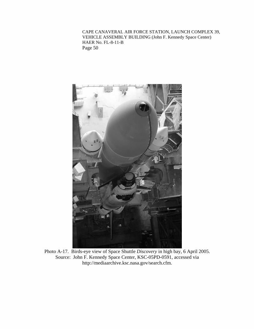
CAPE CANAVERAL AIR FORCE STATION, LAUNCH COMPLEX 39, VEHICLE ASSEMBLY BUILDING (John F. Kennedy Space Center) HAER No. FL-8-11-B
Page 50
Photo A-17. Birds-eye view of Space Shuttle Discovery in high bay, 6 April 2005.
Source: John F. Kennedy Space Center, KSC-05PD-0591, accessed via http://mediaarchive.ksc.nasa.gov/search.cfm.

CAPE CANAVERAL AIR FORCE STATION, LAUNCH COMPLEX 39, VEHICLE ASSEMBLY BUILDING (John F. Kennedy Space Center) HAER No. FL-8-11-B
Page 51
Photo A-18. Space Shuttle Discovery leaving VAB to go to the launch pad, 6 April 2005.
Source: John F. Kennedy Space Center, KSC-05PD-0597, accessed via http://mediaarchive.ksc.nasa.gov/search.cfm.
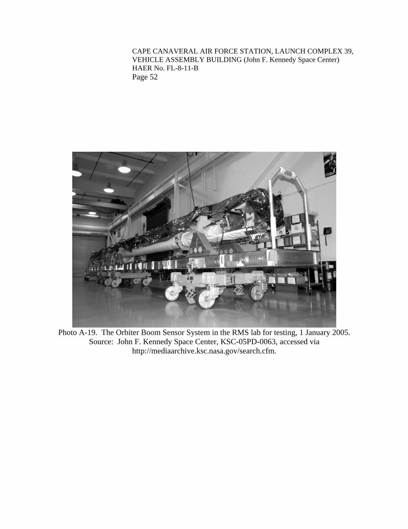
CAPE CANAVERAL AIR FORCE STATION, LAUNCH COMPLEX 39, VEHICLE ASSEMBLY BUILDING (John F. Kennedy Space Center) HAER No. FL-8-11-B
Page 52
Photo A-19. The Orbiter Boom Sensor System in the RMS lab for testing, 1 January 2005.
Source: John F. Kennedy Space Center, KSC-05PD-0063, accessed via http://mediaarchive.ksc.nasa.gov/search.cfm.

HISTORIC AMERICAN ENGINEERING RECORD
INDEX TO PHOTOGRAPHS CAPE CANAVERAL AIR FORCE STATION, LAUNCH COMPLEX 39 HAER No. FL-8-11-B VEHICLE ASSEMBLY BUILDING (John F. Kennedy Space Center) VAB Road, East of Kennedy Parkway North Cape Canaveral Brevard County Florida Penny Rogo Bailes, Photographer; Teresa Norman, Assistant Photographer May-October 2008 (FL-8-11-B-2 through FL-8-11-B-10; 13, 14, 16-46, 108, 109-160) Penny Rogo Bailes, Photographer, May-December 2008 (FL-8-11-B-1, 15, FL-8-11-B-161 through FL-8-11-B-175; FL-8-11-B-176 through FL-8-11-B-193) FL-8-11-B-1 VIEW OF SOUTH ELEVATION, FACING NORTH. FL-8-11-B-2 VIEW OF THE OVERALL SOUTH ELEVATION AND THE LOW BAY’S
EAST ELEVATION, FACING NORTHWEST. FL-8-11-B-3 VIEW OF THE OVERALL SOUTH ELEVATION AND THE HIGH BAY’S
EAST ELEVATION, FACING NORTHWEST. FL-8-11-B-4 VIEW OF EAST ELEVATION, FACING WEST. FL-8-11-B-5 VIEW OF EAST AND NORTH ELEVATIONS, FACING SOUTHWEST. FL-8-11-B-6 VIEW OF NORTH ELEVATION, FACING SOUTH. FL-8-11-B-7 VIEW OF NORTH AND WEST ELEVATIONS, FACING SOUTHEAST. FL-8-11-B-8 VIEW OF WEST ELEVATION, FACING EAST. FL-8-11-B-9 VIEW OF THE OVERALL WEST ELEVATION AND THE HIGH BAY’S
SOUTH ELEVATION, FACING NORTHEAST. FL-8-11-B-10 VIEW OF SOUTH AND WEST ELEVATIONS, FACING NORTHEAST. FL-8-11-B-11 DETAIL VIEW OF SOUTH TRANSFER AISLE DOOR, FACING NORTH. FL-8-11-B-12 DETAIL VIEW OF EXTERIOR SIDE OF SLIDING DOORS TO HB-3,
FACING WEST.

CAPE CANAVERAL AIR FORCE STATION, LAUNCH COMPLEX 39, VEHICLE ASSEMBLY BUILDING (John F. Kennedy Space Center) HAER No. FL-8-11-B
INDEX TO PHOTOGRAPHS (page 2) FL-8-11-B-13 DETAIL VIEW OF EXTERIOR SIDE OF LIFTING DOORS TO HB-3,
FACING WEST. FL-8-11-B-14 DETAIL VIEW OF INTERIOR SIDE OF LIFTING DOORS TO HB-3,
FACING EAST. FL-8-11-B-15 DETAIL VIEW OF EXTERIOR SIDE OF THE NORTH TRANSFER
AISLE DOOR, FACING SOUTH. FL-8-11-B-16 DETAIL VIEW OF INTERIOR SIDE OF THE NORTH TRANSFER AISLE
DOOR, FACING NORTH. FL-8-11-B-17 DETAIL VIEW OF INTERIOR SIDE OF THE LIFTING PORTION OF
THE NORTH TRANSFER AISLE DOOR, FACING NORTH. FL-8-11-B-18 DETAIL VIEW OF THE CONTROL BUTTONS THAT OPEN AND
CLOSE THE SLIDING PORTIONS OF THE NORTH TRANSFER AISLE DOOR, FACING NORTH.
FL-8-11-B-19 DETAIL VIEW SHOWING THE NORTH TRANSFER AISLE DOOR
FULLY OPEN, FACING NORTH. FL-8-11-B-20 OVERALL VIEW OF THE TRANSFER AISLE FROM THE SOUTH END
OF THE VAB’S LOW BAY, FACING NORTH. FL-8-11-B-21 OVERALL VIEW OF THE TRANSFER AISLE FROM THE JUNCTION
OF THE VAB’S LOW AND HIGH BAYS, FACING NORTH. FL-8-11-B-22 OVERALL VIEW OF THE TRANSFER AISLE FROM THE NORTH END
OF THE VAB’S HIGH BAY, FACING SOUTH. FL-8-11-B-23 OVERALL VIEW OF THE TRANSFER AISLE FROM THE JUNCTION
OF THE VAB’S HIGH AND LOW BAYS, FACING SOUTH. FL-8-11-B-24 DETAIL VIEW OF THE 175-TON BRIDGE CRANE WITHIN THE
TRANSFER AISLE, FACING NORTH. FL-8-11-B-25 DETAIL VIEW OF THE ORBITER ORIENTATION LINE ON FLOOR OF
TRANSFER AISLE, BETWEEN HB-3 AND HB-4, FACING WEST.

CAPE CANAVERAL AIR FORCE STATION, LAUNCH COMPLEX 39, VEHICLE ASSEMBLY BUILDING (John F. Kennedy Space Center) HAER No. FL-8-11-B
INDEX TO PHOTOGRAPHS (page 3) FL-8-11-B-26 VIEW OF LOW BAY CELL NOS. 1 (RIGHT) AND 2 (LEFT), FACING
NORTHWEST. FL-8-11-B-27 VIEW OF LOW BAY CELL NOS. 3 (RIGHT) AND 4 (LEFT), FACING
SOUTHWEST. FL-8-11-B-28 VIEW OF LOW BAY CELL NOS. 5 (LEFT) AND 6 (RIGHT), FACING
NORTHEAST. FL-8-11-B-29 VIEW OF LOW BAY CELL NOS. 7 (LEFT) AND 8 (RIGHT), FACING
SOUTHEAST. FL-8-11-B-30 VIEW OF IMAGING LAB DATA COLLECTION AREA, ROOM NO. 3K8,
FACING NORTH. FL-8-11-B-31 VIEW OF IMAGING LAB VIEWING AREA, ROOM NO. 3K9, FACING
SOUTHEAST. FL-8-11-B-32 VIEW OF IMAGING LAB VIEWING AREA, ROOM NO. 3K9, FACING
NORTHWEST. FL-8-11-B-33 VIEW OF KENNEDY AVIONICS TEST SET LABORATORY, ROOM NO.
MM6, FACING NORTH. FL-8-11-B-34 VIEW OF THE ORBITER WHEEL STORAGE DEVICES, ROOM 1M8,
FACING NORTHWEST. FL-8-11-B-35 DETAIL VIEW OF THE TIRE INFLATION CAGE, ROOM 1M8, FACING
NORTHEAST. FL-8-11-B-36 DETAIL VIEW OF TIRE BEAD BREAKER (LEFT) AND PRESSURE
MONITOR PANEL (RIGHT), ROOM 1M9, FACING NORTHWEST. FL-8-11-B-37 DETAIL VIEW OF FREEZER AND GASEOUS NITROGEN PANEL,
ROOM 1M9, FACING SOUTHEAST. FL-8-11-B-38 DETAIL VIEW OF VENT HOOD (LEFT) AND WHEEL LIFT (RIGHT),
ROOM 1M10, FACING SOUTHEAST. FL-8-11-B-39 VIEW OF FLIGHT CREW SYSTEMS, FLIGHT KITS FACILITY, ROOM
NO. 1N12, FACING NORTH.
CAPE CANAVERAL AIR FORCE STATION, LAUNCH COMPLEX 39, VEHICLE ASSEMBLY BUILDING (John F. Kennedy Space Center) HAER No. FL-8-11-B
INDEX TO PHOTOGRAPHS (page 4) FL-8-11-B-40 VIEW OF FLIGHT CREW SYSTEMS, FLIGHT KITS FACILITY, ROOM
NO. 1N12, FACING SOUTH. FL-8-11-B-41 DETAIL VIEW OF ELECTRONICS TEST AREA, FLIGHT KITS
FACILITY, ROOM NO. 1N12, FACING WEST. FL-8-11-B-42 VIEW OF REMOTE MANIPULATOR SYSTEM LAB, ROOM NO. 1N4,
FACING NORTH. FL-8-11-B-43 VIEW OF REMOTE MANIPULATOR SYSTEM LAB, ROOM NO. 1N4,
FACING SOUTHWEST. FL-8-11-B-44 DETAIL VIEW OF TESTING EQUIPMENT, REMOTE MANIPULATOR
SYSTEM LAB, ROOM NO. 1N4, FACING SOUTHEAST. FL-8-11-B-45 VIEW OF HB-1 (VAB HIGH BAY) WITH MOBILE LAUNCHER
PLATFORM (VEHICLE ACCESS PLATFORMS ARE VISIBLE IN THE CENTER), FACING WEST.
FL-8-11-B-46 GENERAL VIEW OF HB-3 (VAB HIGH BAY) FROM LEVEL 16,
FACING EAST. FL-8-11-B-47 GENERAL VIEW OF NORTH VEHICLE ACCESS PLATFORMS, HB-3,
FACING NORTHEAST TOWARDS CEILING. FL-8-11-B-48 GENERAL VIEW OF NORTH VEHICLE ACCESS PLATFORMS, HB-3,
FACING NORTH TOWARDS FLOOR. FL-8-11-B-49 GENERAL VIEW OF VEHICLE ACCESS PLATFORM D-NORTH, HB-3,
FACING NORTH. FL-8-11-B-50 GENERAL VIEW OF VEHICLE ACCESS PLATFORM D-NORTH, HB-3,
FACING NORTHWEST. FL-8-11-B-51 GENERAL VIEW OF THE MAIN FLOOR LEVEL, PLATFORM D-
SOUTH, HB-3, FACING NORTHEAST. FL-8-11-B-52 GENERAL VIEW OF THE MAIN FLOOR LEVEL, PLATFORM D-
SOUTH, HB-3, FACING NORTHWEST.

CAPE CANAVERAL AIR FORCE STATION, LAUNCH COMPLEX 39, VEHICLE ASSEMBLY BUILDING (John F. Kennedy Space Center) HAER No. FL-8-11-B
INDEX TO PHOTOGRAPHS (page 5) FL-8-11-B-53 GENERAL VIEW OF THE SECOND FLOOR LEVEL, PLATFORM D-
SOUTH, HB-3, FACING NORTHWEST. FL-8-11-B-54 DETAIL VIEW OF AP 65, SECOND FLOOR LEVEL, PLATFORM D-
SOUTH, HB-3, FACING NORTHWEST. FL-8-11-B-55 GENERAL VIEW OF THE THIRD FLOOR LEVEL, PLATFORM D-
SOUTH, HB-3, FACING WEST. FL-8-11-B-56 DETAIL VIEW OF WINCH USED TO RAISE AND LOWER HINGED
SECTION OF THIRD FLOOR LEVEL, PLATFORM D-SOUTH, HB-3, FACING WEST.
FL-8-11-B-57 GENERAL VIEW OF THE ROOF LEVEL, PLATFORM D-SOUTH, HB-3,
FACING NORTHEAST. FL-8-11-B-58 DETAIL VIEW OF AP 93W, ROOF LEVEL, PLATFORM D-SOUTH, HB-
3, FACING NORTHWEST. FL-8-11-B-59 DETAIL VIEW OF WINCH USED TO RAISE AND LOWER AP 93W,
ROOF LEVEL, PLATFORM D-SOUTH, HB-3, FACING WEST. FL-8-11-B-60 GENERAL VIEW OF VEHICLE ACCESS PLATFORM B-NORTH, HB-3,
FACING NORTHEAST. FL-8-11-B-61 GENERAL VIEW OF VEHICLE ACCESS PLATFORM B-NORTH, HB-3,
FACING NORTH. FL-8-11-B-62 DETAIL VIEW OF THE ORBITER ACCESS OPENING, SECOND FLOOR
LEVEL, PLATFORM B-NORTH, HB-3, FACING NORTH. FL-8-11-B-63 DETAIL VIEW OF THE ORBITER ACCESS ROOM, SECOND FLOOR
LEVEL, PLATFORM B-NORTH, HB-3, FACING SOUTH. FL-8-11-B-64 DETAIL VIEW OF THE INTERIOR OF THE ORBITER ACCESS ROOM,
SECOND FLOOR LEVEL, PLATFORM B-NORTH, HB-3, FACING NORTHWEST.
FL-8-11-B-65 DETAIL VIEW OF THE OXYGEN ANALYZER FOR THE ORBITER
ACCESS ROOM AND THE PERSONNEL SHOE CLEANER, SECOND FLOOR LEVEL, PLATFORM B-NORTH, HB-3, FACING WEST.

CAPE CANAVERAL AIR FORCE STATION, LAUNCH COMPLEX 39, VEHICLE ASSEMBLY BUILDING (John F. Kennedy Space Center) HAER No. FL-8-11-B
INDEX TO PHOTOGRAPHS (page 6) FL-8-11-B-66 GENERAL VIEW OF THE MAIN FLOOR LEVEL, PLATFORM B-
SOUTH, HB-3, FACING NORTHEAST. FL-8-11-B-67 GENERAL VIEW OF THE MAIN FLOOR LEVEL, PLATFORM B-
SOUTH, HB-3, FACING SOUTHEAST. FL-8-11-B-68 GENERAL VIEW OF THE MAIN FLOOR LEVEL, PLATFORM B-
SOUTH, HB-3, FACING WEST. FL-8-11-B-69 DETAIL VIEW OF HINGED SECTION OF MAIN FLOOR LEVEL,
PLATFORM B-SOUTH, HB-3, FACING NORTHEAST. FL-8-11-B-70 DETAIL VIEW OF AP 50, MAIN FLOOR LEVEL, PLATFORM B-
SOUTH, HB-3, FACING NORTHWEST. FL-8-11-B-71 DETAIL VIEW OF AP 66, MAIN FLOOR LEVEL, PLATFORM B-
NORTH, HB-3, FACING NORTH. FL-8-11-B-72 DETAIL VIEW OF VARIOUS ELECTRICAL PANELS, MAIN FLOOR
LEVEL, PLATFORM B-SOUTH, HB-3, FACING SOUTH. FL-8-11-B-73 GENERAL VIEW OF THE SECOND FLOOR LEVEL, PLATFORM B-
SOUTH, HB-3, FACING NORTHWEST. FL-8-11-B-74 GENERAL VIEW OF THE SECOND FLOOR LEVEL, PLATFORM B-
SOUTH, HB-3, FACING SOUTHEAST. FL-8-11-B-75 DETAIL VIEW OF STORED REMOVABLE PLATFORM BARRIERS,
SECOND FLOOR LEVEL, PLATFORM B-SOUTH, HB-3, FACING SOUTHEAST.
FL-8-11-B-76 GENERAL VIEW OF THE ROOF LEVEL, PLATFORM B-SOUTH, HB-3,
FACING EAST. FL-8-11-B-77 GENERAL VIEW OF VEHICLE ACCESS PLATFORM E-NORTH, HB-3,
FACING NORTH. FL-8-11-B-78 GENERAL VIEW OF VEHICLE ACCESS PLATFORM E-NORTH, HB-3,
FACING NORTHWEST.

CAPE CANAVERAL AIR FORCE STATION, LAUNCH COMPLEX 39, VEHICLE ASSEMBLY BUILDING (John F. Kennedy Space Center) HAER No. FL-8-11-B
INDEX TO PHOTOGRAPHS (page 7) FL-8-11-B-79 DETAIL VIEW OF HINGED SECTION OF MAIN FLOOR LEVEL,
PLATFORM E-NORTH, HB-3, FACING NORTH. FL-8-11-B-80 DETAIL VIEW OF ET VENT VALVE ACTUATION PANEL, MAIN
FLOOR LEVEL, PLATFORM E-NORTH, HB-3, FACING NORTH. FL-8-11-B-81 DETAIL VIEW OF THE PORT SRB ACCESS PLATFORM, SUSPENDED
FROM THE ROOF LEVEL, PLATFORM E-NORTH, HB-3, FACING NORTH.
FL-8-11-B-82 GENERAL VIEW OF THE MAIN FLOOR LEVEL, PLATFORM E-
SOUTH, HB-3, FACING SOUTHEAST. FL-8-11-B-83 GENERAL VIEW OF THE MAIN FLOOR LEVEL, PLATFORM E-
SOUTH, HB-3, FACING NORTHEAST. FL-8-11-B-84 GENERAL VIEW OF THE MAIN FLOOR LEVEL, PLATFORM E-
SOUTH, HB-3, FACING NORTHWEST. FL-8-11-B-85 DETAIL VIEW OF AP 47W AND ITS WINCH, MAIN FLOOR LEVEL,
PLATFORM E-SOUTH, HB-3, FACING NORTH. FL-8-11-B-86 DETAIL VIEW OF AP 47E AND ITS WINCH, MAIN FLOOR LEVEL,
PLATFORM E-SOUTH, HB-3, FACING NORTHEAST. FL-8-11-B-87 DETAIL VIEW OF VIDEO CAMERA, MAIN FLOOR LEVEL,
PLATFORM E-SOUTH, HB-3, FACING SOUTHWEST. FL-8-11-B-88 DETAIL VIEW OF CONTROL PANEL FOR POSITIONING PLATFORM
E-SOUTH, MAIN FLOOR LEVEL, PLATFORM E-SOUTH, HB-3, FACING SOUTH.
FL-8-11-B-89 DETAIL VIEW OF ELECTRICAL PANEL, MAIN FLOOR LEVEL,
PLATFORM E-SOUTH, HB-3, FACING EAST. FL-8-11-B-90 DETAIL VIEW OF THE ORBITER NOSE ACCESS PLATFORMS, MAIN
FLOOR LEVELS, PLATFORMS E-SOUTH AND E-NORTH, HB-3, FACING NORTH.
FL-8-11-B-91 GENERAL VIEW OF THE ROOF LEVEL, PLATFORM E-SOUTH, HB-3,
FACING NORTHEAST.

CAPE CANAVERAL AIR FORCE STATION, LAUNCH COMPLEX 39, VEHICLE ASSEMBLY BUILDING (John F. Kennedy Space Center) HAER No. FL-8-11-B
INDEX TO PHOTOGRAPHS (page 8) FL-8-11-B-92 GENERAL VIEW OF THE ROOF LEVELS, PLATFORMS E-SOUTH AND
E-NORTH, HB-3, FACING NORTHEAST. FL-8-11-B-93 DETAIL VIEW OF SRB/ET ACCESS PANELS, ROOF LEVELS,
PLATFORMS E-SOUTH AND E-NORTH, HB-3, FACING NORTHEAST. FL-8-11-B-94 DETAIL VIEW OF SRB/ET ACCESS PANELS, THROUGH VEHICLE
ACCESS PLATFORMS E-NORTH, E-SOUTH, B-NORTH, AND B-SOUTH, HB-3, FACING NORTH.
FL-8-11-B-95 GENERAL VIEW OF VEHICLE ACCESS PLATFORM C-NORTH, HB-3,
FACING NORTHEAST. FL-8-11-B-96 GENERAL VIEW OF VEHICLE ACCESS PLATFORM C-NORTH, HB-3,
FACING NORTHWEST. FL-8-11-B-97 GENERAL VIEW OF THE MAIN FLOOR LEVEL, PLATFORM C-
SOUTH, HB-3, FACING SOUTHEAST. FL-8-11-B-98 GENERAL VIEW OF THE MAIN FLOOR LEVEL, PLATFORM C-
SOUTH, HB-3, FACING NORTHEAST. FL-8-11-B-99 GENERAL VIEW OF THE MAIN FLOOR LEVEL, PLATFORM C-
SOUTH, HB-3, FACING WEST. FL-8-11-B-100 DETAIL VIEW OF THE CONTROL PANELS FOR PLATFORM C-
SOUTH, HB-3, FACING SOUTH. FL-8-11-B-101 DETAIL VIEW OF ELECTRICAL PANELS, MAIN FLOOR LEVEL,
PLATFORM C-SOUTH, HB-3, FACING SOUTH. FL-8-11-B-102 GENERAL VIEW OF THE SECOND FLOOR LEVEL, PLATFORM C-
SOUTH, HB-3, FACING NORTHWEST. FL-8-11-B-103 DETAIL VIEW OF THE COMMUNICATIONS PANEL, SECOND FLOOR
LEVEL, PLATFORM C-SOUTH, HB-3, FACING WEST. FL-8-11-B-104 GENERAL VIEW OF THE ROOF LEVEL, PLATFORM C-NORTH, HB-3,
FACING NORTHEAST.

CAPE CANAVERAL AIR FORCE STATION, LAUNCH COMPLEX 39, VEHICLE ASSEMBLY BUILDING (John F. Kennedy Space Center) HAER No. FL-8-11-B
INDEX TO PHOTOGRAPHS (page 9) FL-8-11-B-105 GENERAL VIEW OF THE BRIDGE CRANE USED IN HB-3 AND HB-4,
FACING SOUTHEAST. FL-8-11-B-106 DETAIL VIEW OF THE BRIDGE CRANE HOOKS USED IN HB-3 AND
HB-4, FACING SOUTHWEST. FL-8-11-B-107 DETAIL VIEW OF A FOREIGN OBSTACLE DEBRIS NET, HB-3,
FACING WEST. FL-8-11-B-108 DETAIL VIEW OF A HANDHELD “BUMPER,” USED TO AID IN
POSITIONING THE ORBITER DURING STACKING PROCEDURES. FL-8-11-B-109 GENERAL VIEW OF HB-2, FACING EAST. FL-8-11-B-110 GENERAL VIEW OF HB-2, FACING SOUTHWEST. FL-8-11-B-111 GENERAL VIEW OF HB-2, FACING NORTH. FL-8-11-B-112 GENERAL VIEW OF HB-2, FACING NORTHWEST. FL-8-11-B-113 DETAIL VIEW OF RAILROAD TRACKS THROUGH HB-2, FACING
WEST. FL-8-11-B-114 DETAIL VIEW OF AN SRB SEGMENT SITTING ON A SPECIAL PAD
OF CONCRETE, HB-2, FACING NORTHEAST. FL-8-11-B-115 OVERALL VIEW OF EXTERNAL TANK CHECK-OUT CELLS, HB-2,
FACING NORTH. FL-8-11-B-116 OVERALL VIEW OF SECOND THROUGH SIXTH LEVELS OF EAST
EXTERNAL TANK CELL, HB-2, FACING NORTH. FL-8-11-B-117 OVERALL VIEW OF SIXTH THROUGH NINTH LEVELS OF EAST
EXTERNAL TANK CELL, HB-2, FACING NORTHWEST. FL-8-11-B-118 GENERAL VIEW OF THE FIRST LEVEL OF THE EXTERNAL TANK
CHECK-OUT CELLS, HB-2, FACING SOUTHWEST. FL-8-11-B-119 GENERAL VIEW OF THE FIRST LEVEL OF THE EXTERNAL TANK
CHECK-OUT CELLS, HB-2, FACING SOUTHEAST.

CAPE CANAVERAL AIR FORCE STATION, LAUNCH COMPLEX 39, VEHICLE ASSEMBLY BUILDING (John F. Kennedy Space Center) HAER No. FL-8-11-B
INDEX TO PHOTOGRAPHS (page 10) FL-8-11-B-120 GENERAL VIEW OF THE SECOND LEVEL OF THE EXTERNAL TANK
CHECK-OUT CELLS, HB-2, FACING SOUTHWEST. FL-8-11-B-121 VIEW OF THE WEST CHECK-OUT CELL, SECOND LEVEL OF THE
EXTERNAL TANK CHECK-OUT CELLS, HB-2, FACING SOUTHEAST. FL-8-11-B-122 VIEW OF THE EAST CHECK-OUT CELL, SECOND LEVEL OF THE
EXTERNAL TANK CHECK-OUT CELLS, HB-2, FACING NORTHEAST. FL-8-11-B-123 DETAIL OF AFT STABILIZER, SECOND LEVEL OF THE EXTERNAL
TANK CHECK-OUT CELLS, HB-2, FACING NORTH. FL-8-11-B-124 DETAIL OF THE HELIUM VENT VALVE, SECOND LEVEL OF THE
EXTERNAL TANK CHECK-OUT CELLS, HB-2, FACING NORTH. FL-8-11-B-125 DETAIL OF THE EXTERNAL TANK PNEUMATIC CONTROL PANELS
FOR HB-2 AND HB-4, SECOND LEVEL OF THE EXTERNAL TANK CHECK-OUT CELLS, HB-2, FACING EAST.
FL-8-11-B-126 DETAIL OF THE GASEOUS NITROGEN PRESSURIZATION AND
CHECKOUT PANEL, SECOND LEVEL OF THE EXTERNAL TANK CHECK-OUT CELLS, HB-2, FACING SOUTHWEST.
FL-8-11-B-127 DETAIL OF THE HELIUM PRESSURIZATION AND CHECK-OUT
PANEL, SECOND LEVEL OF THE EXTERNAL TANK CHECK-OUT CELLS, HB-2, FACING NORTHWEST.
FL-8-11-B-128 GENERAL VIEW OF THE THIRD LEVEL OF THE EXTERNAL TANK
CHECK-OUT CELLS, HB-2, FACING NORTHWEST. FL-8-11-B-129 VIEW OF THE EAST CHECK-OUT CELL, THIRD LEVEL OF THE
EXTERNAL TANK CHECK-OUT CELLS, HB-2, FACING NORTHEAST. FL-8-11-B-130 VIEW OF THE WEST CHECK-OUT CELL, THIRD LEVEL OF THE
EXTERNAL TANK CHECK-OUT CELLS, HB-2, FACING NORTHWEST. FL-8-11-B-131 DETAIL OF A TYPICAL SINGLE-PRONGED MOVEABLE PLATFORM
SUPPORT, THIRD LEVEL OF THE EXTERNAL TANK CHECK-OUT CELLS, HB-2, FACING SOUTHEAST.

CAPE CANAVERAL AIR FORCE STATION, LAUNCH COMPLEX 39, VEHICLE ASSEMBLY BUILDING (John F. Kennedy Space Center) HAER No. FL-8-11-B
INDEX TO PHOTOGRAPHS (page 11) FL-8-11-B-132 GENERAL VIEW OF THE FOURTH LEVEL OF THE EXTERNAL TANK
CHECK-OUT CELLS, HB-2, FACING EAST. FL-8-11-B-133 VIEW OF THE EAST CHECK-OUT CELL, FOURTH LEVEL OF THE
EXTERNAL TANK CHECK-OUT CELLS, HB-2, FACING NORTHEAST. FL-8-11-B-134 VIEW OF THE WEST CHECK-OUT CELL, FOURTH LEVEL OF THE
EXTERNAL TANK CHECK-OUT CELLS, HB-2, FACING SOUTHWEST. FL-8-11-B-135 DETAIL OF THE CONTROLS FOR ONE-HALF OF THE MOVEABLE
PLATFORMS, FOURTH LEVEL OF THE EXTERNAL TANK CHECK-OUT CELLS, HB-2, FACING SOUTHWEST.
FL-8-11-B-136 GENERAL VIEW OF THE FIFTH LEVEL OF THE EXTERNAL TANK
CHECK-OUT CELLS, HB-2, FACING WEST. FL-8-11-B-137 VIEW OF THE EAST CHECK-OUT CELL, FIFTH LEVEL OF THE
EXTERNAL TANK CHECK-OUT CELLS, HB-2, FACING SOUTHWEST. FL-8-11-B-138 VIEW OF THE WEST CHECK-OUT CELL, FIFTH LEVEL OF THE
EXTERNAL TANK CHECK-OUT CELLS, HB-2, FACING SOUTH. FL-8-11-B-139 GENERAL VIEW OF THE SIXTH LEVEL OF THE EXTERNAL TANK
CHECK-OUT CELLS, HB-2, FACING SOUTHWEST. FL-8-11-B-140 VIEW OF THE EAST CHECK-OUT CELL, SIXTH LEVEL OF THE
EXTERNAL TANK CHECK-OUT CELLS, HB-2, FACING NORTHEAST. FL-8-11-B-141 VIEW OF THE WEST CHECK-OUT CELL, SIXTH LEVEL OF THE
EXTERNAL TANK CHECK-OUT CELLS, HB-2, FACING NORTHWEST. FL-8-11-B-142 DETAIL OF A WINCH FOR A MOVEABLE PLATFORM ON THE SIXTH
LEVEL OF THE EXTERNAL TANK CHECK-OUT CELLS, HB-2, FACING EAST.
FL-8-11-B-143 DETAIL OF AN EXTERNAL TANK SUPPORT ARM, SIXTH LEVEL OF
THE EXTERNAL TANK CHECK-OUT CELLS, HB-2, FACING NORTHEAST.

CAPE CANAVERAL AIR FORCE STATION, LAUNCH COMPLEX 39, VEHICLE ASSEMBLY BUILDING (John F. Kennedy Space Center) HAER No. FL-8-11-B
INDEX TO PHOTOGRAPHS (page 12) FL-8-11-B-144 DETAIL OF THE LIQUID HYDROGEN AND LIQUID OXYGEN VENT
VALVES, SIXTH LEVEL OF THE EXTERNAL TANK CHECK-OUT CELLS, HB-2, FACING NORTHEAST.
FL-8-11-B-145 VIEW OF THE EXTERNAL TANK VENT VALVE ACTUATION PANEL,
SIXTH LEVEL OF THE EXTERNAL TANK CHECK-OUT CELLS, HB-2, FACING SOUTH.
FL-8-11-B-146 GENERAL VIEW OF THE SEVENTH LEVEL OF THE EXTERNAL
TANK CHECK-OUT CELLS, HB-2, FACING EAST. FL-8-11-B-147 VIEW OF THE WEST CHECK-OUT CELL, SEVENTH LEVEL OF THE
EXTERNAL TANK CHECK-OUT CELLS, HB-2, FACING SOUTHEAST. FL-8-11-B-148 VIEW OF THE EAST CHECK-OUT CELL, SEVENTH LEVEL OF THE
EXTERNAL TANK CHECK-OUT CELLS, HB-2, FACING NORTHWEST. FL-8-11-B-149 VIEW OF THE EAST CHECK-OUT CELL, EIGHTH LEVEL OF THE
EXTERNAL TANK CHECK-OUT CELLS, HB-2, FACING EAST. FL-8-11-B-150 VIEW OF THE WEST CHECK-OUT CELL, EIGHTH LEVEL OF THE
EXTERNAL TANK CHECK-OUT CELLS, HB-2, FACING SOUTH. FL-8-11-B-151 DETAIL OF A WINCH FOR A MOVEABLE PLATFORM ON THE
EIGHTH LEVEL OF THE EXTERNAL TANK CHECK-OUT CELLS, HB-2, FACING NORTH.
FL-8-11-B-152 DETAIL OF THE CONTROLS FOR ONE-HALF OF THE MOVEABLE
PLATFORMS, EIGHTH LEVEL OF THE EXTERNAL TANK CHECK-OUT CELLS, HB-2, FACING NORTHWEST.
FL-8-11-B-153 GENERAL VIEW OF THE NINTH LEVEL OF THE EXTERNAL TANK
CHECK-OUT CELLS, HB-2, FACING NORTHEAST. FL-8-11-B-154 VIEW OF THE WEST CHECK-OUT CELL, NINTH LEVEL OF THE
EXTERNAL TANK CHECK-OUT CELLS, HB-2, FACING SOUTHEAST. FL-8-11-B-155 VIEW OF THE EAST CHECK-OUT CELL PLATFORM IN ITS
“STORAGE POSITION”, NINTH LEVEL OF THE EXTERNAL TANK CHECK-OUT CELLS, HB-2, FACING NORTHWEST.

CAPE CANAVERAL AIR FORCE STATION, LAUNCH COMPLEX 39, VEHICLE ASSEMBLY BUILDING (John F. Kennedy Space Center) HAER No. FL-8-11-B
INDEX TO PHOTOGRAPHS (page 13) FL-8-11-B-156 DETAIL OF A HAND-OPERATED MOVEABLE PLATFORM, SEVENTH
LEVEL OF THE EXTERNAL TANK CHECK-OUT CELLS, HB-4, FACING WEST.
FL-8-11-B-157 DETAIL OF A TYPICAL DOUBLE-PRONGED MOVEABLE PLATFORM
SUPPORT, SEVENTH LEVEL OF THE EXTERNAL TANK CHECK-OUT CELLS, HB-4, FACING NORTH.
FL-8-11-B-158 GENERAL VIEW OF HB-4, FACING WEST. FL-8-11-B-159 GENERAL VIEW OF HB-4 WITH OLD SRB PLATFORMS TO THE
RIGHT, FACING NORTHWEST. FL-8-11-B-160 DETAIL OF JIB HOIST ASSOCIATED WITH OLD SRB PLATFORMS,
HB-4, FACING NORTHWEST. Photograph Nos. FL-8-11-B-161 through FL-8-11-B-193 are photocopies of engineering drawings, and are 8” x 10” enlargements from 4” x 5” negatives. Original drawings are located at the Engineering Documentation Office, NASA KSC, Florida. FL-8-11-B-161 Photocopy of drawing
VEHICLE ASSEMBLY BUILDING MODIFICATIONS NASA, John F. Kennedy Space Center, Florida Drawing 79K05424, Seelye Stevenson Value & Knecht, March, 1975
SITE WORK, GENERAL AREA PLAN Sheet 8 of 207 FL-8-11-B-162 Photocopy of drawing
LAUNCH COMPLEX 39 NASA, John F. Kennedy Space Center, Florida File Number 203-100, Urbahn-Roberts-Seelye-Moran, October, 1963
VOLUME 14, HIGH BAY – ARCHITECTURAL, TITLE SHEET Sheet 14-01 FL-8-11-B-163 Photocopy of drawing
LAUNCH COMPLEX 39 NASA John F. Kennedy Space Center, Florida File Number 203-100, Urbahn-Roberts-Seelye-Moran, October 1963 VERTICAL ASSEMBLY BUILDING, HIGH AND LOW BAY AREA, MASTER PLAN FLOOR 1, LEVEL 0’:0” Sheet 14-03

CAPE CANAVERAL AIR FORCE STATION, LAUNCH COMPLEX 39, VEHICLE ASSEMBLY BUILDING (John F. Kennedy Space Center) HAER No. FL-8-11-B
INDEX TO PHOTOGRAPHS (page 14)
FL-8-11-B-164 Photocopy of drawing LAUNCH COMPLEX 39 NASA John F. Kennedy Space Center, Florida File Number 203-100, Urbahn-Roberts-Seelye-Moran, October 1963 VERTICAL ASSEMBLY BUILDING, HIGH BAY AREA, SOUTH ELEVATION Sheet 14-20
FL-8-11-B-165 Photocopy of drawing
LAUNCH COMPLEX 39 NASA John F. Kennedy Space Center, Florida File Number 203-100, Urbahn-Roberts-Seelye-Moran, October 1963 VERTICAL ASSEMBLY BUILDING, HIGH BAY AREA, EAST ELEVATION Sheet 14-19
FL-8-11-B-166 Photocopy of drawing
LAUNCH COMPLEX 39 NASA John F. Kennedy Space Center, Florida File Number 203-100, Urbahn-Roberts-Seelye-Moran, October 1963 VERTICAL ASSEMBLY BUILDING, HIGH BAY AREA, NORTH ELEVATION Sheet 14-18
FL-8-11-B-167 Photocopy of drawing
LAUNCH COMPLEX 39 NASA John F. Kennedy Space Center, Florida File Number 203-100, Urbahn-Roberts-Seelye-Moran, October 1963 VERTICAL ASSEMBLY BUILDING, HIGH BAY AREA, WEST ELEVATION Sheet 14-17
FL-8-11-B-168 Photocopy of drawing
VEHICLE ASSEMBLY BUILDING MODIFICATIONS, HIGH BAY AREA NASA John F. Kennedy Space Center, Florida File Number 79K05424, Seelye Stevenson Value & Knecht, March 1975 TRANSFER AISLE NORTH DOOR, ARCHITECTURAL NORTH ELEVATION AND MISC. DETAILS Sheet 78 of 207
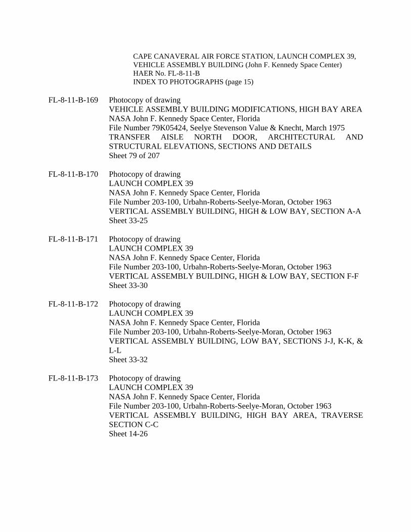
CAPE CANAVERAL AIR FORCE STATION, LAUNCH COMPLEX 39, VEHICLE ASSEMBLY BUILDING (John F. Kennedy Space Center) HAER No. FL-8-11-B
INDEX TO PHOTOGRAPHS (page 15) FL-8-11-B-169 Photocopy of drawing
VEHICLE ASSEMBLY BUILDING MODIFICATIONS, HIGH BAY AREA NASA John F. Kennedy Space Center, Florida File Number 79K05424, Seelye Stevenson Value & Knecht, March 1975 TRANSFER AISLE NORTH DOOR, ARCHITECTURAL AND STRUCTURAL ELEVATIONS, SECTIONS AND DETAILS Sheet 79 of 207
FL-8-11-B-170 Photocopy of drawing LAUNCH COMPLEX 39 NASA John F. Kennedy Space Center, Florida File Number 203-100, Urbahn-Roberts-Seelye-Moran, October 1963 VERTICAL ASSEMBLY BUILDING, HIGH & LOW BAY, SECTION A-A Sheet 33-25
FL-8-11-B-171 Photocopy of drawing LAUNCH COMPLEX 39 NASA John F. Kennedy Space Center, Florida File Number 203-100, Urbahn-Roberts-Seelye-Moran, October 1963 VERTICAL ASSEMBLY BUILDING, HIGH & LOW BAY, SECTION F-F Sheet 33-30
FL-8-11-B-172 Photocopy of drawing LAUNCH COMPLEX 39 NASA John F. Kennedy Space Center, Florida File Number 203-100, Urbahn-Roberts-Seelye-Moran, October 1963 VERTICAL ASSEMBLY BUILDING, LOW BAY, SECTIONS J-J, K-K, & L-L Sheet 33-32
FL-8-11-B-173 Photocopy of drawing LAUNCH COMPLEX 39 NASA John F. Kennedy Space Center, Florida File Number 203-100, Urbahn-Roberts-Seelye-Moran, October 1963 VERTICAL ASSEMBLY BUILDING, HIGH BAY AREA, TRAVERSE SECTION C-C Sheet 14-26

CAPE CANAVERAL AIR FORCE STATION, LAUNCH COMPLEX 39, VEHICLE ASSEMBLY BUILDING (John F. Kennedy Space Center) HAER No. FL-8-11-B
INDEX TO PHOTOGRAPHS (page 16) FL-8-11-B-174 Photocopy of drawing
LAUNCH COMPLEX 39 NASA John F. Kennedy Space Center, Florida File Number 203-100, Urbahn-Roberts-Seelye-Moran, October 1963 VERTICAL ASSEMBLY BUILDING, HIGH BAY AREA, LONGINTUDINAL SECTION N-N Sheet 14-33
FL-8-11-B-175 Photocopy of drawing VEHICLE ASSEMBLY BUILDING NASA John F. Kennedy Space Center, Florida File Number 79K06740, NASA, November 1975 SPACE & WEIGHT ALLOCATION, ORBITER PATH IN TRANSFER AISLE Sheet 6
FL-8-11-B-176 Photocopy of drawing VEHICLE ASSEMBLY BUILDING MODIFICATIONS NASA John F. Kennedy Space Center, Florida File Number 79K05424, Seelye Stevenson Value & Knecht, March 1975 ALL PLATFORMS-ARCHITECTURAL, GENERAL ARRANGEMENT, EAST-WEST ELEVATIONS Sheet 12 of 207
FL-8-11-B-177 Photocopy of drawing VEHICLE ASSEMBLY BUILDING MODIFICATIONS NASA John F. Kennedy Space Center, Florida File Number 79K05424, Seelye Stevenson Value & Knecht, March 1975 HIGH BAY 3, EXTENSIBLE WORK PLATFORM ‘D’, MAIN FLOOR PLAN, ARCHITECTURAL Sheet 39 of 207
FL-8-11-B-178 Photocopy of drawing
VEHICLE ASSEMBLY BUILDING MODIFICATIONS NASA John F. Kennedy Space Center, Florida File Number 79K05424, Seelye Stevenson Value & Knecht, March 1975 HIGH BAY 3, EXTENSIBLE WORK PLATFORM ‘D’, 2ND FLOOR PLAN, ARCHITECTURAL Sheet 38 of 207

CAPE CANAVERAL AIR FORCE STATION, LAUNCH COMPLEX 39, VEHICLE ASSEMBLY BUILDING (John F. Kennedy Space Center) HAER No. FL-8-11-B
INDEX TO PHOTOGRAPHS (page 17) FL-8-11-B-179 Photocopy of drawing
VEHICLE ASSEMBLY BUILDING MODIFICATIONS NASA John F. Kennedy Space Center, Florida File Number 79K05424, Seelye Stevenson Value & Knecht, March 1975 HIGH BAY 3, EXTENSIBLE WORK PLATFORM ‘D’, 3RD FLOOR PLAN, ARCHITECTURAL Sheet 37 of 207
FL-8-11-B-180 Photocopy of drawing VEHICLE ASSEMBLY BUILDING MODIFICATIONS NASA John F. Kennedy Space Center, Florida File Number 79K05424, Seelye Stevenson Value & Knecht, March 1975 HIGH BAY 3, EXTENSIBLE WORK PLATFORM ‘D’, ROOF PLAN, ARCHITECTURAL Sheet 36 of 207
FL-8-11-B-181 Photocopy of drawing VEHICLE ASSEMBLY BUILDING MODIFICATIONS NASA John F. Kennedy Space Center, Florida File Number 79K05424, Seelye Stevenson Value & Knecht, March 1975 HIGH BAY 3, EXTENSIBLE WORK PLATFORM ‘B’, MAIN FLOOR PLAN, ARCHITECTURAL Sheet 30 of 207
FL-8-11-B-182 Photocopy of drawing VEHICLE ASSEMBLY BUILDING MODIFICATIONS NASA John F. Kennedy Space Center, Florida File Number 79K05424, Seelye Stevenson Value & Knecht, March 1975 HIGH BAY 3, EXTENSIBLE WORK PLATFORM ‘B’, 2ND FLOOR PLAN, ARCHITECTURAL Sheet 29 of 207
FL-8-11-B-183 Photocopy of drawing
VEHICLE ASSEMBLY BUILDING MODIFICATIONS NASA John F. Kennedy Space Center, Florida File Number 79K05424, Seelye Stevenson Value & Knecht, March 1975 HIGH BAY 3, EXTENSIBLE WORK PLATFORM ‘B’, ROOF PLAN, ARCHITECTURAL Sheet 28 of 207

CAPE CANAVERAL AIR FORCE STATION, LAUNCH COMPLEX 39, VEHICLE ASSEMBLY BUILDING (John F. Kennedy Space Center) HAER No. FL-8-11-B
INDEX TO PHOTOGRAPHS (page 18) FL-8-11-B-184 Photocopy of drawing
VEHICLE ASSEMBLY BUILDING MODIFICATIONS NASA John F. Kennedy Space Center, Florida File Number 79K05424, Seelye Stevenson Value & Knecht, March 1975 HIGH BAY 3, EXTENSIBLE WORK PLATFORM ‘E’, MAIN FLOOR PLAN, ARCHITECTURAL Sheet 23 of 207
FL-8-11-B-185 Photocopy of drawing
VEHICLE ASSEMBLY BUILDING MODIFICATIONS NASA John F. Kennedy Space Center, Florida File Number 79K05424, Seelye Stevenson Value & Knecht, March 1975 HIGH BAY 3, EXTENSIBLE WORK PLATFORM ‘E’, ROOF PLAN, ARCHITECTURAL Sheet 22 of 207
FL-8-11-B-186 Photocopy of drawing VEHICLE ASSEMBLY BUILDING MODIFICATIONS NASA John F. Kennedy Space Center, Florida File Number 79K05424, Seelye Stevenson Value & Knecht, March 1975 HIGH BAY 3, EXTENSIBLE WORK PLATFORM ‘C’, MAIN FLOOR PLAN, ARCHITECTURAL Sheet 16 of 207
FL-8-11-B-187 Photocopy of drawing VEHICLE ASSEMBLY BUILDING MODIFICATIONS NASA John F. Kennedy Space Center, Florida File Number 79K05424, Seelye Stevenson Value & Knecht, March 1975 HIGH BAY 3, EXTENSIBLE WORK PLATFORM ‘C’, 2ND FLOOR PLAN, ARCHITECTURAL Sheet 15 of 207
FL-8-11-B-188 Photocopy of drawing
VEHICLE ASSEMBLY BUILDING MODIFICATIONS NASA John F. Kennedy Space Center, Florida File Number 79K05424, Seelye Stevenson Value & Knecht, March 1975 HIGH BAY 3, EXTENSIBLE WORK PLATFORM ‘C’, ROOF PLAN, ARCHITECTURAL Sheet 14 of 207

CAPE CANAVERAL AIR FORCE STATION, LAUNCH COMPLEX 39, VEHICLE ASSEMBLY BUILDING (John F. Kennedy Space Center) HAER No. FL-8-11-B
INDEX TO PHOTOGRAPHS (page 19) FL-8-11-B-189 Photocopy of drawing
VAB HB-2 & 4 ET HOLDING CELLS, UPGRADE TO CHECKOUT CELLS NASA John F. Kennedy Space Center, Florida File Number 79K33180, Reynolds, Smith & Hill, February 1991 GENERAL ARRANGEMENT, PLAN & ELEVATIONS Sheet 4
FL-8-11-B-190 Photocopy of drawing VAB HB-2 & 4 ET HOLDING CELLS, UPGRADE TO CHECKOUT CELLS NASA John F. Kennedy Space Center, Florida File Number 79K33180, Reynolds, Smith & Hill, February 1991 H.B.-2, PLANS AT LEVELS 1,2,&3 Sheet 6
FL-8-11-B-191 Photocopy of drawing VAB HB-2 & 4 ET HOLDING CELLS, UPGRADE TO CHECKOUT CELLS NASA John F. Kennedy Space Center, Florida File Number 79K33180, Reynolds, Smith & Hill, February 1991 H.B.-2, PLANS AT LEVELS 4,5,&6 Sheet 7
FL-8-11-B-192 Photocopy of drawing VAB HB-2 & 4 ET HOLDING CELLS, UPGRADE TO CHECKOUT CELLS NASA John F. Kennedy Space Center, Florida File Number 79K33180, Reynolds, Smith & Hill, February 1991 H.B.-2, PLANS AT LEVELS 7,8,&9 Sheet 8
FL-8-11-B-193 Photocopy of drawing VAB HB-2 & 4 ET HOLDING CELLS, UPGRADE TO CHECKOUT CELLS NASA John F. Kennedy Space Center, Florida File Number 79K33180, Reynolds, Smith & Hill, February 1991 HINGED PANEL EQUIPMENT SCHEDULE Sheet 28