Embed Size (px)
Citation preview

IP Office 3.2 Phone Installation Guide
15-601042 Issue 11e (27th June 2006)
© 2006 Avaya Inc. All Rights Reserved.
Notice While reasonable efforts were made to ensure that the information in this document was complete and accurate at the time of printing, Avaya Inc. can assume no liability for any errors. Changes and corrections to the information in this document may be incorporated in future releases.
Documentation Disclaimer Avaya Inc. is not responsible for any modifications, additions, or deletions to the original published version of this documentation unless such modifications, additions, or deletions were performed by Avaya.
Link Disclaimer Avaya Inc. is not responsible for the contents or reliability of any linked Web sites referenced elsewhere within this Documentation, and Avaya does not necessarily endorse the products, services, or information described or offered within them. We cannot guarantee that these links will work all of the time and we have no control over the availability of the linked pages.
License USE OR INSTALLATION OF THE PRODUCT INDICATES THE END USER’S ACCEPTANCE OF THE TERMS SET FORTH HEREIN AND THE GENERAL LICENSE TERMS AVAILABLE ON THE AVAYA WEBSITE AT http://support.avaya.com/LicenseInfo/ (“GENERAL LICENSE TERMS”). IF YOU DO NOT WISH TO BE BOUND BY THESE TERMS, YOU MUST RETURN THE PRODUCT(S) TO THE POINT OF PURCHASE WITHIN TEN (10) DAYS OF DELIVERY FOR A REFUND OR CREDIT.
Avaya grants End User a license within the scope of the license types described below. The applicable number of licenses and units of capacity for which the license is granted will be one (1), unless a different number of licenses or units of capacity is specified in the Documentation or other materials available to End User. “Designated Processor” means a single stand-alone computing device. “Server” means a Designated Processor that hosts a software application to be accessed by multiple users. “Software” means the computer programs in object code, originally licensed by Avaya and ultimately utilized by End User, whether as stand-alone Products or pre-installed on Hardware. “Hardware” means the standard hardware Products, originally sold by Avaya and ultimately utilized by End User.
License Type(s): Designated System(s) License (DS). End User may install and use each copy of the Software on only one Designated Processor, unless a different number of Designated Processors is indicated in the Documentation or other materials available to End User. Avaya may require the Designated Processor(s) to be identified by type, serial number, feature key, location or other specific designation, or to be provided by End User to Avaya through electronic means established by Avaya specifically for this purpose.
Copyright Except where expressly stated otherwise, the Product is protected by copyright and other laws respecting proprietary rights. Unauthorized reproduction, transfer, and or use can be a criminal, as well as a civil, offense under the applicable law.
Third-Party Components Certain software programs or portions thereof included in the Product may contain software distributed under third party agreements (“Third Party Components”), which may contain terms that expand or limit rights to use certain portions of the Product (“Third Party Terms”). Information identifying Third Party Components and the Third Party Terms that apply to them is available on Avaya’s web site at: http://support.avaya.com/ThirdPartyLicense/
Avaya Fraud Intervention If you suspect that you are being victimized by toll fraud and you need technical assistance or support, call Technical Service Center Toll Fraud Intervention Hotline at +1-800-643-2353 for the United States and Canada. Suspected security vulnerabilities with Avaya Products should be reported to Avaya by sending mail to: [email protected].
For additional support telephone numbers, see the Avaya Support web site (http://www.avaya.com/support).
Trademarks Avaya and the Avaya logo are registered trademarks of Avaya Inc. in the United States of America and other jurisdictions. Unless otherwise provided in this document, marks identified by “®,” “™” and “SM” are registered marks, trademarks and service marks, respectively, of Avaya Inc. All other trademarks are the property of their respective owners.
Documentation information For the most current versions of documentation, go to the Avaya Support web site (http://www.avaya.com/support) or the IP Office Knowledge Base (http://marketingtools.avaya.com/knowledgebase/).
Avaya Support Avaya provides a telephone number for you to use to report problems or to ask questions about your contact center. The support telephone number is 1- 800- 242- 2121 in the United States. For additional support telephone numbers, see the Avaya Web site: http://www.avaya.com/support.
Phone Installation Guide Page iii IP Office 3.2 15-601042 Issue 11e (27th June 2006)
Table of Contents IP Office IP Phones .................................................................................................................... 1 Introduction................................................................................................................................................. 1 Small Installation (5 or less phones)........................................................................................................... 3 Large Installation (More than 5 phones)..................................................................................................... 4 Wireless Installation.................................................................................................................................... 5 Installation Requirements ........................................................................................................................... 6 Network Assessment.................................................................................................................................. 7 Voice Compression Channels .................................................................................................................... 8 QoS ............................................................................................................................................................ 8 Potential VoIP Problems............................................................................................................................. 9 User PC Connection................................................................................................................................. 10 Power Supply Options .............................................................................................................................. 11
Spare Wire Power Options .................................................................................................................. 11 802.3af Power over Ethernet Options.................................................................................................. 12
TFTP Options ........................................................................................................................................... 13 TFTP Introduction ................................................................................................................................ 13 Using a Control Unit Memory Card for TFTP....................................................................................... 14 TFTP Application ................................................................................................................................. 15
Installation ................................................................................................................................ 17 1. Preparation ........................................................................................................................................... 17 1a. 4601 and 5601 Installation ................................................................................................................. 18 1b. Creating a 46xxsettings.txt File .......................................................................................................... 18 2. Phone Connection ................................................................................................................................ 19 3a. DHCP Address Installation ................................................................................................................. 19 3b. Static Address Installation .................................................................................................................. 20 4. Phone Registration ............................................................................................................................... 21 5. Extension & User Setup ....................................................................................................................... 21 Manually Creating Extensions .................................................................................................................. 22 Phone Security ......................................................................................................................................... 23 Listing Registered Phones........................................................................................................................ 23 Static Administration............................................................................................................... 25 Static Administration Options ................................................................................................................... 25 Entering Data for Administrative Options ................................................................................................. 25 QoS Option Settings................................................................................................................................. 26 Secondary Ethernet (Hub)/IR Interface Enable/Disable ........................................................................... 26 Appendix A: Miscellaneous .................................................................................................... 27 Error Messages ........................................................................................................................................ 27 View Administrative Details ...................................................................................................................... 28 Reset System Values ............................................................................................................................... 29 Self-Test Procedure.................................................................................................................................. 29 Site Specific Option Number .................................................................................................................... 30 Automatic Gain Control ............................................................................................................................ 30 Appendix B: IP Telephone Files ............................................................................................. 31 IP Telephone Files.................................................................................................................................... 31 The 46XX Upgrade Script File.................................................................................................................. 32 The 46XX Settings Script File................................................................................................................... 32
46XX Settings ...................................................................................................................................... 33 Appendix C: Scenarios for the Restart Process ................................................................... 35 Restart Scenarios ..................................................................................................................................... 35 Boot File Needs Upgrading ...................................................................................................................... 36 No Application File or Application File Needs Upgrading ......................................................................... 37 Correct Boot File and Application File Already Loaded ............................................................................ 37
IP Phone Installation Manual
Phone Installation Guide Page iv IP Office 3.2 15-601042 Issue 11e (27th June 2006)
Appendix D: Infrared Dialling.................................................................................................. 39 Infrared Dialling ........................................................................................................................................ 39 Enabling the IR Port ................................................................................................................................. 40 Dialling Phone Numbers........................................................................................................................... 40
Palm Organizer .................................................................................................................................... 40 Windows Pocket PC ............................................................................................................................ 41
Beaming Files During a Call ..................................................................................................................... 41 Palm Organizer .................................................................................................................................... 41
Appendix E: Alternate DHCP Setup........................................................................................ 43 Alternate DHCP Servers for Avaya IP Phone Installation ........................................................................ 43 Using Windows 2000 Server .................................................................................................................... 43
1. Checking for DHCP.......................................................................................................................... 43 2. Windows 2000 DHCP Setup for H.323 IP Phones .......................................................................... 44
Alternate Options...................................................................................................................................... 46 Appendix F: WML Operation................................................................................................... 47 WML Server Setup ................................................................................................................................... 47
What WML is Supported ...................................................................................................................... 47 Testing WML Browsing Using Xitami ....................................................................................................... 48
1. Introduction ...................................................................................................................................... 48 2. Installing the Web Server................................................................................................................. 48 3. Configuring the Xitami Web Server for WAP ................................................................................... 48 4. Installing Sample WML Pages ......................................................................................................... 49
Setting the Home Page ............................................................................................................................ 50 Apache Web Server WML Configuration.................................................................................................. 51 Microsoft IIS Web Server WML Configuration.......................................................................................... 51 Open URL Entry ....................................................................................................................................... 52
Case 1. Input Box Followed by an Anchor Tag.................................................................................... 52 Case 2. Input Box Followed by an A Tag............................................................................................. 52 Case 3. Input Box Followed by a Submit Button.................................................................................. 52 Case 4. Input Box Followed by an Anchor Tag Where the Anchor Tag Already Displays HTTP:// ..... 52
Appendix G: 3616/3620/3626 Installation............................................................................... 53 3616/3620/3626 Spectralink Installation................................................................................................... 53 Access Points ........................................................................................................................................... 53 Index.......................................................................................................................................... 55
Phone Installation Guide Page 1 IP Office 3.2 15-601042 Issue 11e (27th June 2006)
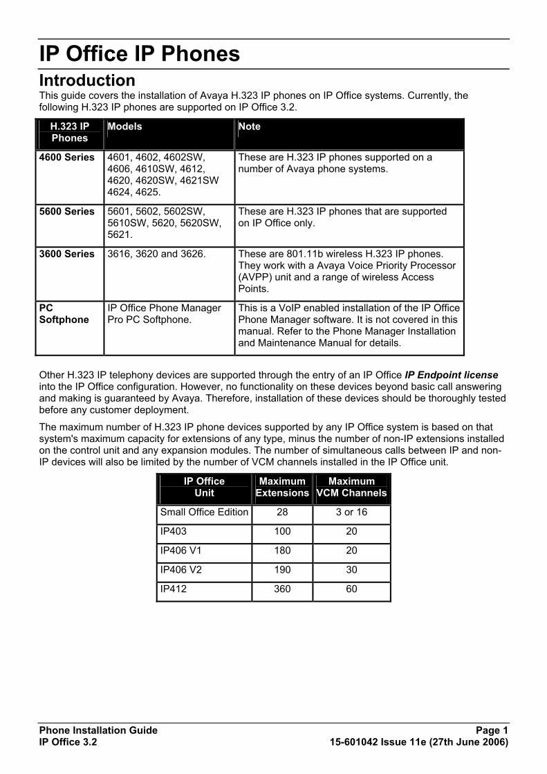
IP Office IP Phones Introduction This guide covers the installation of Avaya H.323 IP phones on IP Office systems. Currently, the following H.323 IP phones are supported on IP Office 3.2.
H.323 IP Phones
Models Note
4600 Series 4601, 4602, 4602SW, 4606, 4610SW, 4612, 4620, 4620SW, 4621SW 4624, 4625.
These are H.323 IP phones supported on a number of Avaya phone systems.
5600 Series 5601, 5602, 5602SW, 5610SW, 5620, 5620SW, 5621.
These are H.323 IP phones that are supported on IP Office only.
3600 Series 3616, 3620 and 3626. These are 801.11b wireless H.323 IP phones. They work with a Avaya Voice Priority Processor (AVPP) unit and a range of wireless Access Points.
PC Softphone
IP Office Phone Manager Pro PC Softphone.
This is a VoIP enabled installation of the IP Office Phone Manager software. It is not covered in this manual. Refer to the Phone Manager Installation and Maintenance Manual for details.
Other H.323 IP telephony devices are supported through the entry of an IP Office IP Endpoint license into the IP Office configuration. However, no functionality on these devices beyond basic call answering and making is guaranteed by Avaya. Therefore, installation of these devices should be thoroughly tested before any customer deployment.
The maximum number of H.323 IP phone devices supported by any IP Office system is based on that system's maximum capacity for extensions of any type, minus the number of non-IP extensions installed on the control unit and any expansion modules. The number of simultaneous calls between IP and non-IP devices will also be limited by the number of VCM channels installed in the IP Office unit.
IP Office Unit
Maximum Extensions
Maximum VCM Channels
Small Office Edition 28 3 or 16
IP403 100 20
IP406 V1 180 20
IP406 V2 190 30
IP412 360 60
IP Phone Installation Manual
Phone Installation Guide Page 2 IP Office 3.2 15-601042 Issue 11e (27th June 2006)
Notes
• IP Phone Software Version H.323 IP phones on an IP Office system must use the IP Phone software installed with the IP Office Manager application. Other versions of IP Phone software may not have been tested with IP Office and so should not be used unless IP Office support is specifically mentioned in their accompanying documentation.
• DHCP versus Static IP Installation Though static IP installation of H.323 IP phones is possible, installation using DHCP is strongly recommended. The use of DHCP eases both the installation process and future maintenance and administration. In addition, following a boot file upgrade, all static address settings are lost and must be re-entered.
• Network Assessment High quality voice transmission across an IP network requires careful assessment of many factors. Therefore:
• We strongly recommend that IP phone installation is only done by installers with VoIP experience.
• The whole customer network must be assessed for its suitability for VoIP, before installation. Avaya may refuse to support any installation where the results of a network assessment cannot be supplied.

IP Office IP Phones
Phone Installation Guide Page 3 IP Office 3.2 15-601042 Issue 11e (27th June 2006)
Small Installation (5 or less phones) The diagram below shows the simplest installation scenario, suitable when only a few H.323 IP phones are being installed. This type of installation is only supported for up to 5 IP phone devices.
• DHCP Server
The IP Office unit is acting as the DHCP server for the H.323 IP phones.
• For scenarios where the customer already has a DHCP server or wants to use an alternate DHCP server, details of configuring 3-party DHCP servers to support H.323 IP phones are included. See Large Installation.
• H.323 Gatekeeper The IP Office unit is acting as the H.323 Gatekeeper for the H.323 IP phones.
• TFTP Server The IP Office Manager application is acting as the TFTP server used to provide the H.323 IP phones with appropriate software for operation on the IP Office system.
• In this instance, the Manager application is only being run to perform its TFTP role during the installation process. Once installed, the H.323 IP phones look for a TFTP server whenever restarted but will eventually restart if no TFTP server is found.
• If a permanent TFTP server is required, use of IP Office Manager is not recommended. Details of TFTP Server Options are included in the installation process.
IP Phone Installation Manual
Phone Installation Guide Page 4 IP Office 3.2 15-601042 Issue 11e (27th June 2006)
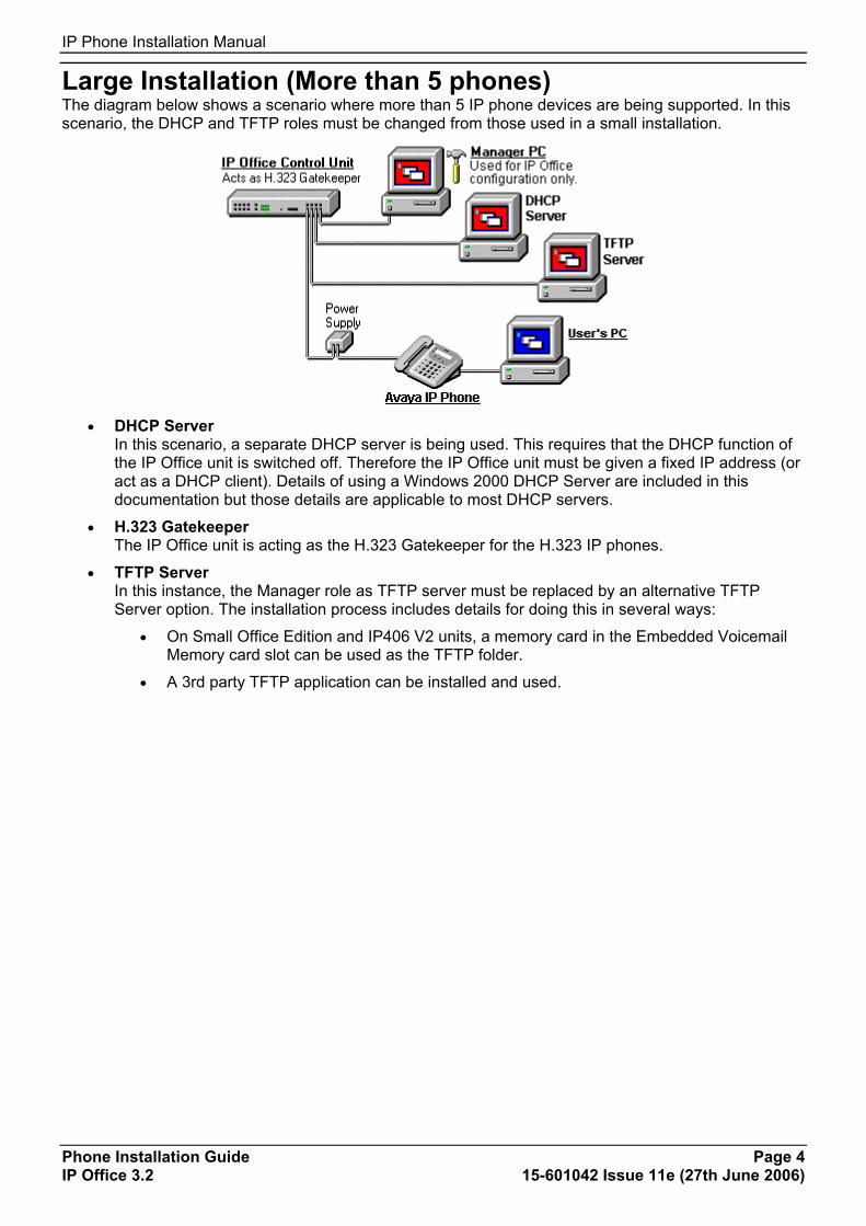
Large Installation (More than 5 phones) The diagram below shows a scenario where more than 5 IP phone devices are being supported. In this scenario, the DHCP and TFTP roles must be changed from those used in a small installation.
• DHCP Server
In this scenario, a separate DHCP server is being used. This requires that the DHCP function of the IP Office unit is switched off. Therefore the IP Office unit must be given a fixed IP address (or act as a DHCP client). Details of using a Windows 2000 DHCP Server are included in this documentation but those details are applicable to most DHCP servers.
• H.323 Gatekeeper The IP Office unit is acting as the H.323 Gatekeeper for the H.323 IP phones.
• TFTP Server In this instance, the Manager role as TFTP server must be replaced by an alternative TFTP Server option. The installation process includes details for doing this in several ways:
• On Small Office Edition and IP406 V2 units, a memory card in the Embedded Voicemail Memory card slot can be used as the TFTP folder.
• A 3rd party TFTP application can be installed and used.
IP Office IP Phones
Phone Installation Guide Page 5 IP Office 3.2 15-601042 Issue 11e (27th June 2006)
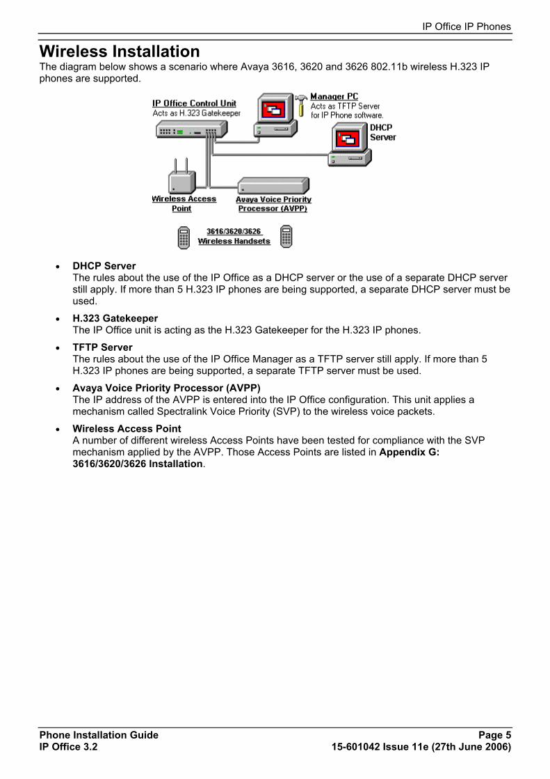
Wireless Installation The diagram below shows a scenario where Avaya 3616, 3620 and 3626 802.11b wireless H.323 IP phones are supported.
• DHCP Server
The rules about the use of the IP Office as a DHCP server or the use of a separate DHCP server still apply. If more than 5 H.323 IP phones are being supported, a separate DHCP server must be used.
• H.323 Gatekeeper The IP Office unit is acting as the H.323 Gatekeeper for the H.323 IP phones.
• TFTP Server The rules about the use of the IP Office Manager as a TFTP server still apply. If more than 5 H.323 IP phones are being supported, a separate TFTP server must be used.
• Avaya Voice Priority Processor (AVPP) The IP address of the AVPP is entered into the IP Office configuration. This unit applies a mechanism called Spectralink Voice Priority (SVP) to the wireless voice packets.
• Wireless Access Point A number of different wireless Access Points have been tested for compliance with the SVP mechanism applied by the AVPP. Those Access Points are listed in Appendix G: 3616/3620/3626 Installation.

IP Phone Installation Manual
Phone Installation Guide Page 6 IP Office 3.2 15-601042 Issue 11e (27th June 2006)
Installation Requirements To install an IP phone on IP Office, the following items are required:
• Extension Number and User Details: A full listing of the planned extension number and user name details is required. The planned extension number must be unused and is requested by the phone during installation.
• Power Supply: Each phone requires a power supply. H.323 IP phones do not draw power from the phone switch. A number of options exist for how power is supplied to the phones. See Power Supply Options.
• LAN Socket: An RJ45 Ethernet LAN connection point is required for each phone.
• Category 5 Cabling: All LAN cables and LAN cable infrastructure used with H.323 IP phones should use CAT5 cabling. Existing CAT3 cabling may be used but will be limited to 10Mbps (maximum).
• LAN Cables: Check that an RJ45 LAN cable has been supplied with the IP phone for connection to the power supply unit. You will also need an additional RJ45 LAN cable for connection from the power unit to the customer LAN.
• A further RJ45 LAN cable can be used to connect the user's PC to the LAN via the IP phone [not supported on 4601, 4602, 5601 and 5602 H.323 IP phones].
• Voice Compression Module: The IP Office Unit must have voice compression channels available. The number of voice compression channels limits the number of simultaneous VoIP calls:
• On Small Office Edition units, either 3 or 16 voice compression channels are pre-built into the unit.
• On all other control units, voice compression channels are provided by fitting a Voice Compression Module.
• DHCP Server: The IP Office Unit can perform this role for up to 5 IP phone devices. If another DHCP server already exists, this may be able to do DHCP for the H.323 IP phones, see Alternate DHCP Servers. Static IP addressing can also be used, if required, but is not recommended.
• TFTP Server: A PC running the IP Office Manager application can perform this role for up to 5 H.323 IP phones. Otherwise one of the other TFTP Server Options must be used.
• H323 Gatekeeper: The IP Office Unit performs this role.
• IP Office Manager PC: A PC running Manager is required for IP Office Unit configuration changes. This PC should have a static IP address.
• IP Telephone Software: The software for IP phone installation is installed into the IP Office Manager program folder during Manager installation.
• Licence Keys: IP Office supported H.323 IP phones do not need a licence key entered on the system.
IP Office IP Phones
Phone Installation Guide Page 7 IP Office 3.2 15-601042 Issue 11e (27th June 2006)
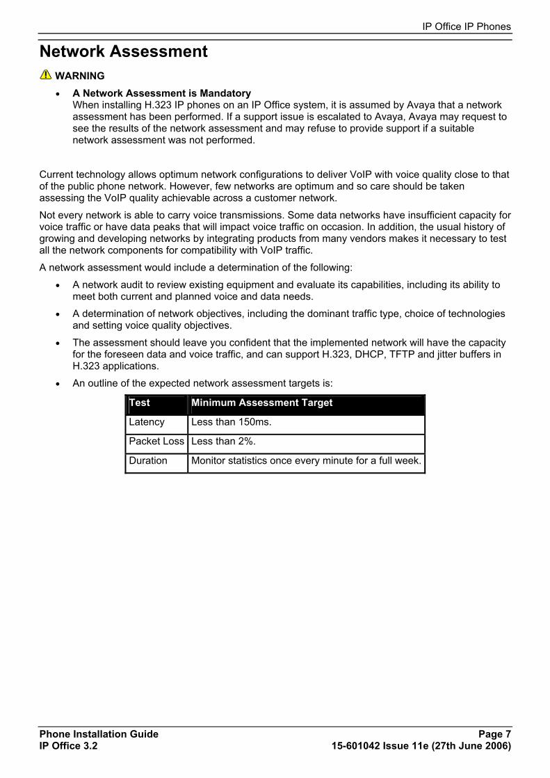
Network Assessment WARNING
• A Network Assessment is Mandatory When installing H.323 IP phones on an IP Office system, it is assumed by Avaya that a network assessment has been performed. If a support issue is escalated to Avaya, Avaya may request to see the results of the network assessment and may refuse to provide support if a suitable network assessment was not performed.
Current technology allows optimum network configurations to deliver VoIP with voice quality close to that of the public phone network. However, few networks are optimum and so care should be taken assessing the VoIP quality achievable across a customer network.
Not every network is able to carry voice transmissions. Some data networks have insufficient capacity for voice traffic or have data peaks that will impact voice traffic on occasion. In addition, the usual history of growing and developing networks by integrating products from many vendors makes it necessary to test all the network components for compatibility with VoIP traffic.
A network assessment would include a determination of the following:
• A network audit to review existing equipment and evaluate its capabilities, including its ability to meet both current and planned voice and data needs.
• A determination of network objectives, including the dominant traffic type, choice of technologies and setting voice quality objectives.
• The assessment should leave you confident that the implemented network will have the capacity for the foreseen data and voice traffic, and can support H.323, DHCP, TFTP and jitter buffers in H.323 applications.
• An outline of the expected network assessment targets is:
Test Minimum Assessment Target
Latency Less than 150ms.
Packet Loss Less than 2%.
Duration Monitor statistics once every minute for a full week.

IP Phone Installation Manual
Phone Installation Guide Page 8 IP Office 3.2 15-601042 Issue 11e (27th June 2006)
Voice Compression Channels IP Office Voice Compression Channels are used when a voice call goes between a device on the IP Office's data network (that is, an IP trunk or extension) and a device on the IP Office's TDM telephony interface (that is, a non-IP trunk or extension).
When using Direct Media (the default), calls between IP device (trunks or extensions) do not normally need a Voice Compression Channel once the call is connected. However, they do use a VCM channel for call signalling tones, music-on-hold, etc.
Voice Compression Channels are provided by installing a VCM card into the IP Office unit. These cards are available in a number of different capacities (i.e. number of Voice Compression Channels). The maximum capacity of an IP Office system depends on the unit type as follows:
IP Office Unit Voice Compression Channel Capacity
Small Office Edition
Supplied with either 3 or 16 VCM channels pre-built into the unit. These cannot be upgraded.
IP403 Supports a single VCM card with up to 20 channels.
IP406 V1 Supports a single VCM card with up to 20 channels.
IP406 V2 Supports a single VCM card with up to 30 channels.
IP412 Supports any two VCM cards totalling up to 60 channels.
The Voice Compression Channels support G.723 (6k3) and G.729a (8k) compression codecs and provide echo cancellation for high latency circuits. H.323 IP phones support G.711, G.729a and G.729b, thus G.729a is normally auto-negotiated when these phones are used on IP Office.
VCM cards exist with the following capacities.
• VCM 5, VCM 10, VCM 20 and VCM 30: these cards support 25ms echo cancellation.
• VCM 4, VCM 8, VCM 16 and VCM 24: these cards support 64ms echo cancellation.
QoS When transporting voice over low speed links it is possible for normal data packets (1500 byte packets) to prevent or delay voice packets (typically 67 or 31 bytes) from getting across the link. This can cause a very unacceptable speech quality.
Therefore, it is vital that all traffic routers and switches in the network to have some form of Quality of Service (QoS) mechanism. QoS routers are essential to ensure low speech latency and to maintain sufficient audible quality.
IP Office supports the DiffServ (RFC2474) QoS mechanism. This is based upon using a Type of Service (ToS) field in the IP packet header. On its WAN interfaces, IP Office uses this to prioritize voice and voice signalling packets. It also fragments large data packets and, where supported, provides VoIP header compression to minimize the WAN overhead.
Note • IP Office does not perform QoS for its Ethernet ports including the WAN Ethernet port on the
Small Office Edition.
IP Office IP Phones
Phone Installation Guide Page 9 IP Office 3.2 15-601042 Issue 11e (27th June 2006)
Potential VoIP Problems It is likely that any fault on a network, regardless of its cause, will initially show up as a degradation in the quality of VoIP operation. This is regardless of whether the fault is with the VoIP telephony equipment. Therefore, by installing a VoIP solution, you must be aware that you will become the first point of call for diagnosing and assessing all potential customer network issues.
Potential Problems • End-to-End Matching Standards:
VoIP depends upon the support and selection of the same voice compression, header compression and QoS standards throughout all stages of the calls routing. The start and end points must be using the same compression methods. All intermediate points must support DiffServ QoS.
• Avoid Hubs: Hubs introduce echo and congestion points. If the customer network requires LAN connections beyond the capacity of the IP Office Unit itself, Ethernet switches should be used. Even if this is not the case, Ethernet switches are recommended as they allow traffic prioritization to be implemented for VoIP devices and for other device such as the Voicemail Server PC.
• Power Supply Conditioning, Protection and Backup: Traditional phone systems provide power to all their attached phone devices from a single source. In a VoIP installation, the same care and concern that goes into providing power conditioning, protection and backup to the central phone system, must now be applied to all devices on the IP network.
• Multicasting: In a data only network, it is possible for an incorrectly installed printer or hub card to multicast traffic without that fault being immediately identified. On a VoIP network incorrect multicasting will quickly affect VoIP calls and features.
• Duplicate IP Addressing: Duplicate addresses is a frequent issue.
• Excessive Utilization: A workstation that constantly transmits high traffic levels can flood a network, causing VoIP service to disappear.
• Network Access: An IP network is much more open to users connecting a new device or installing software on existing devices that then impacts on VoIP.
• Cabling Connections: Technically VoIP can (bandwidth allowing) be run across any IP network connection. In practice, Cat5 cabling is essential.
IP Phone Installation Manual
Phone Installation Guide Page 10 IP Office 3.2 15-601042 Issue 11e (27th June 2006)
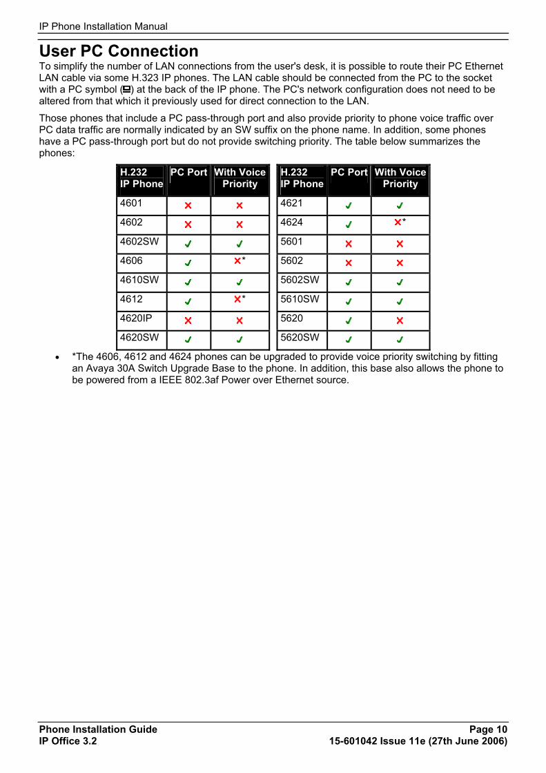
User PC Connection To simplify the number of LAN connections from the user's desk, it is possible to route their PC Ethernet LAN cable via some H.323 IP phones. The LAN cable should be connected from the PC to the socket with a PC symbol ( ) at the back of the IP phone. The PC's network configuration does not need to be altered from that which it previously used for direct connection to the LAN.
Those phones that include a PC pass-through port and also provide priority to phone voice traffic over PC data traffic are normally indicated by an SW suffix on the phone name. In addition, some phones have a PC pass-through port but do not provide switching priority. The table below summarizes the phones:
H.232 IP Phone
PC Port With Voice Priority
H.232 IP Phone
PC Port With Voice Priority
4601 4621
4602 4624 *
4602SW 5601
4606 * 5602
4610SW 5602SW
4612 * 5610SW
4620IP 5620
4620SW 5620SW
• *The 4606, 4612 and 4624 phones can be upgraded to provide voice priority switching by fitting an Avaya 30A Switch Upgrade Base to the phone. In addition, this base also allows the phone to be powered from a IEEE 802.3af Power over Ethernet source.

IP Office IP Phones
Phone Installation Guide Page 11 IP Office 3.2 15-601042 Issue 11e (27th June 2006)
Power Supply Options Each H.323 IP phone requires a power supply. They do not draw power from the IP Office phone system. Listed below are the power supply options that can be used.
Note • For phones being used with an EU24 or EU24BL unit, an 1151C1 or 1151C2 must be used. Use
with an EU24 or EU24BL, adds less than 1W. This also applies for 4621SW being used with a backlight.
Phone Typical Worst Case IEEE 802.3af
4601, 4602, 5601, 5602 3.5W 4.6W Class 2
4602SW, 5602SW 4.1W 5.0W Class 2
4606, 4612, 4624 4.1W 5.0W Class 0
4610SW, 5610 4.0W 6.0W Class 2
4620 7.7W 9.9W Class 3
4621SW 5.9W 8.0W Class 3
4625SW 4.9W 6.45W Class 3
Spare Wire Power Options The following power supplies use the normally unused pin 7 & 8 connections in the CAT3 or CAT5 network cable. This is referred to as "spare wire" or "mid-span" power supply units.
• Avaya 1151C1 Power Supply Unit (PSU) A power supply unit for a single IP phone. Has a LINE port for the LAN cable from the IP Office, and a PHONE port for the LAN cable to the IP phone. Power into the PSU requires a 90 to 264V AC, 47 to 63HZ mains supply. A green LED indicates when power is available.
• Avaya 1151C2 Power Supply Unit
Same as the 1151C1 above but with integral battery backup. When AC mains supply is removed, the battery will power the IP phone for between 8 hours at light load (2 Watts) and 15 minutes at full load (20 Watts). A green LED indicates when power is available. A yellow LED indicates when the backup is charging. The green LED flashes when the phone is running from the backup battery.
IP Phone Installation Manual
Phone Installation Guide Page 12 IP Office 3.2 15-601042 Issue 11e (27th June 2006)
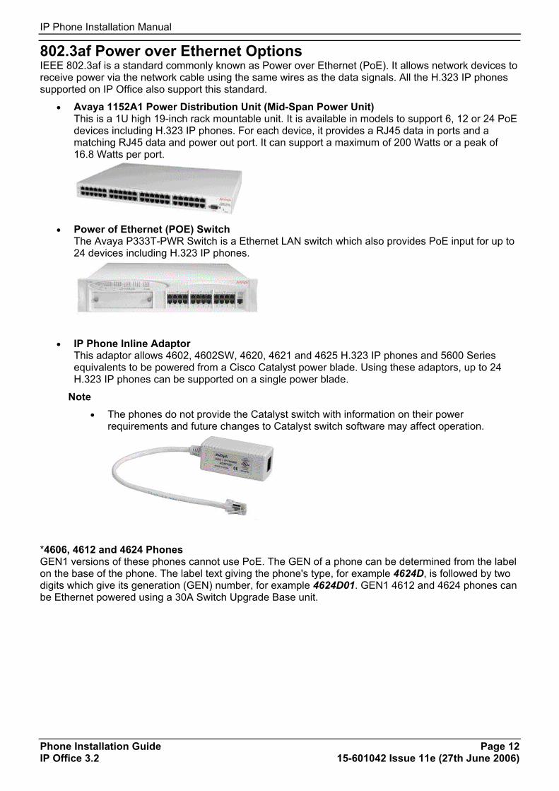
802.3af Power over Ethernet Options IEEE 802.3af is a standard commonly known as Power over Ethernet (PoE). It allows network devices to receive power via the network cable using the same wires as the data signals. All the H.323 IP phones supported on IP Office also support this standard.
• Avaya 1152A1 Power Distribution Unit (Mid-Span Power Unit) This is a 1U high 19-inch rack mountable unit. It is available in models to support 6, 12 or 24 PoE devices including H.323 IP phones. For each device, it provides a RJ45 data in ports and a matching RJ45 data and power out port. It can support a maximum of 200 Watts or a peak of 16.8 Watts per port.
• Power of Ethernet (POE) Switch
The Avaya P333T-PWR Switch is a Ethernet LAN switch which also provides PoE input for up to 24 devices including H.323 IP phones.
• IP Phone Inline Adaptor This adaptor allows 4602, 4602SW, 4620, 4621 and 4625 H.323 IP phones and 5600 Series equivalents to be powered from a Cisco Catalyst power blade. Using these adaptors, up to 24 H.323 IP phones can be supported on a single power blade.
Note • The phones do not provide the Catalyst switch with information on their power
requirements and future changes to Catalyst switch software may affect operation.
*4606, 4612 and 4624 Phones GEN1 versions of these phones cannot use PoE. The GEN of a phone can be determined from the label on the base of the phone. The label text giving the phone's type, for example 4624D, is followed by two digits which give its generation (GEN) number, for example 4624D01. GEN1 4612 and 4624 phones can be Ethernet powered using a 30A Switch Upgrade Base unit.
IP Office IP Phones
Phone Installation Guide Page 13 IP Office 3.2 15-601042 Issue 11e (27th June 2006)
TFTP Options TFTP Introduction In order to load and upgrade their operation software, IP phones search for a TFTP server loaded with the appropriate files whenever they are restarted.
• If using DHCP, the TFTP server address is set as part of the DHCP options. In the case of the IP Office being used as the DHCP server, this is done by setting the TFTP Server IP Address in the IP Office configuration (System | System).
• If not using DHCP, the TFTP server address is entered as part of the static address installation of each phone.
• A fixed address for the TFTP server is required. However, the TFTP server does not need to be running permanently. If the phones restart and the TFTP server is not present, they will eventually timeout waiting for a TFTP response from the server.
The following options are available for TFTP servers:
1. IP Office Manager When running, the IP Office Manager acts as a TFTP server. TFTP activity is shown in its TFTP Log (View | TFTP Log). This solution is only supported for simultaneous TFTP request from up to 5 devices. Due to its role as a system configuration tool, the Manager application should not be left running permanently.
2. IP Office Unit Memory Card The Small Office Edition and IP406 V2 control units can act as TFTP servers. To do this, they require a memory card installed with the IP phone software files. The IP Office Embedded Voicemail memory cards or third-party memory cards can be used. Transferring the software files onto the card will reduce its message storage capacity. In this solution, the IP address of the IP Office LAN1 is used as the TFTP server address. This solution can be used to provide a permanent TFTP server.
3. Third-TFTP Software TFTP Server software is available from many sources including Avaya. Depending on the software, it can be used as a permanent TFTP server, set to run as a service or to autorun during PC startup. In this solution, the IP address of the PC running the software is used as the TFTP server address.
What files are required on the TFTP server? Solutions 2 and 3 above, require that the appropriate software files are copied from the IP Office Manager application folder to the root directory of the TFTP server.
The .bin files used for H.323 IP phones with IP Office 3.2 are listed below. These files are located in the IPSets Firmware folder on the IP Office Administrator Applications CD and are installed to the program directory of the IP Office Manager application. Note that the software level of each file, indicated by the numeric suffix on the file name, may change.
4601dape1_82.bin
4601dbte1_82.bin
4602dape1_82.bin
4602dbte1_82.bin
4602sape1_82.bin
4602sbte1_82.bin
5601ape1810.bin
5601bte1810.bin
5602dape1806.bin
5602dbte1806.bin
5602sape1806.bin
5602sbte1806.bin
a10d01b2_2.bin
a20d01a2_2.bin
a20d01b2_2.bin
b10d01b2_2.bin
b20d01a2_2.bin
b20d01b2_2.bin
bbla0_83.bin
def06r1_8_3.bin
def24r1_8_3.bin
i10c01a2_2.bin
i10d01a2_2.bin
i20d01a2_2.bin
x10d01a2_2.bin
x20d01a2_2.bin

IP Phone Installation Manual
Phone Installation Guide Page 14 IP Office 3.2 15-601042 Issue 11e (27th June 2006)
Using a Control Unit Memory Card for TFTP The Compact Flash memory card used with the Small Office Edition and IP406 V2 systems can be used to store files other than those used for embedded voicemail.
• Non-Avaya supplied Compact Flash memory cards can be used for this type of file storage. However, they will not support embedded voicemail.
• If an Avaya supplied memory card is used, any files stored in this way will reduce the message storage capacity of the Compact Flash memory card.
Configuring the File Source This process allows a specified PC to send files to the memory card and tells the IP Office system to use the memory card
1. Using Manager, receive the IP Office system's configuration.
2. On the System tab of the System form, set the File Writer IP Address to the IP address of the PC from which sending files to the memory card will be allowed.
3. Send this configuration back to the IP Office unit and allow it to reboot. 4. Within Windows, select Start | Run.
5. Enter cmd and then click OK.
6. Within the command window, you can use TFTP to upload files to the memory card. For example:
c:\tftp -i 192.168.42.1 put d:\IPSets Firmware\4601dbtel1_82.bin 7. The above command will send the file d:\IPSets Firmware\4601dbtel1_82.bin to the IP
Office units LAN1 IP address. For additional information about the TFTP command, enter TFTP. If a destination needs specifying, the memory card is treated as the IP Office's drive a:.
8. Receive the IP Office system's configuration again.
9. On the System tab of the System form, set the TFTP Server IP Address to the unit's own LAN1 IP address.
10. Send this configuration back to the IP Office unit and allow it to reboot. The IP Office system will now look on the memory card for any files it needs to download following a reboot.
11. If in future an upgrade or file transfer from the Manager PC is required, the TFTP Server IP Address will first need to be changed back to the Manager PC's IP address.
IP Office IP Phones
Phone Installation Guide Page 15 IP Office 3.2 15-601042 Issue 11e (27th June 2006)
TFTP Application Any third-party TFTP application can be used to provide TFTP support for the H.323 IP phones. Such an application is available from Avaya. Perform a search for TFTP on the http://support.avaya.com website to download this application and full instructions for its usage.
If IP Office is being used for DHCP, the IP address of the PC running the TFTP software should be set in IP Office configuration. If using a alternate DHCP server, the IP address of the PC running the TFTP software should be set in the 176 options scope for the H.323 IP phones.
If using the TFTP application, follow the downloaded instructions and then make the following changes:
1. Run the application and select System | Setup.
2. Select the Outbound tab.
3. In the Outbound file path, enter either of the following:
• If installed onto the same PC as IP Office Manager, set the file path to the IP Office Manager program folder. otherwise;
• Copy the required .bin files to a location on the PC and set to the file path to match the location. For a full list of the .bin files, refer to Appendix B: IP Telephone Files.

Phone Installation Guide Page 17 IP Office 3.2 15-601042 Issue 11e (27th June 2006)
Installation 1. Preparation Check the following before beginning installation:
1. Manager PC Static Address: Ensure that the Manager PC has been given a static IP address.
2. Voice Compression Module: The IP Office Unit must be fitted with a Voice Compression Module (VCM). For a Small Office Edition unit, a number of Voice Compression Channels are preinstalled on the motherboard.
• Start the IP Office Monitor application. The initial lines of Monitor output include the item VCOMP= which will state the number of Voice Compression Channels installed in the control unit.
3. DHCP Server If not using the IP Office for DHCP, check that the alternate DHCP server has been configured for the IP phones. See Appendix E. Alternate DHCP Setup.
4. Control Unit Settings: Using the Manager Application, open the configuration and select the System form. Check the following:
a. System Name: In the System tab ensure that a Name for the IP Office Unit has been entered.
b. TFTP Server IP Address: In the LAN1 tab, enter the IP address of the TFTP server as the TFTP Server IP Address.
• For installations of 5 or less H.323 IP phones this can be the IP address of the PC running Manager.
• If a memory card is being used on a Small Office Edition or IP406 V2, enter the IP address of the IP Office's LAN1.
• If a third-party TFTP server is being used, set the IP address to the address of the PC running that software.
c. Gatekeeper Settings: In the Gatekeeper tab, ensure that Gatekeeper Enabled and Auto-create Extn Enable are selected. If you do not want to install using auto-create extension, you will need to configure the required extensions and user at this stage, see Manually Creating Extensions.
d. If you have made any changes, upload the new configuration to the IP Office Unit.
e. Within Manager, select File | Preferences and ensure that the address is 255.255.255.255, otherwise TFTP will not work.
5. IP Phone Software: The software for IP phone installation is supplied on the IP Office Administration CD. The files are copied into the Manager folder during installation of the Manager application.
• An additional file (46xxsettings.txt) is also required. See 1a. Creating a 46xxsettings.txt File .
6. Manager and TFTP Log: Leave Manager running. It is also useful to have Manager's TFTP Log visible (select View | TFTPLog). This will display the progress of file requests.
7. Extension Number and User Name Details: A full listing of the planned extension number and user name details is required. The planned extension number must be unused and is requested by the phone during installation.
IP Phone Installation Manual
Phone Installation Guide Page 18 IP Office 3.2 15-601042 Issue 11e (27th June 2006)
1a. 4601 and 5601 Installation The 4601 and 5601 H.323 IP phones do not have a display screen to assist with installation and diagnostics.
The only method of installation supported is DHCP and this means the preparation requirements listed in 1. Preparation are essential for successful installation.
During installation, the phone obtains and stores the IP addresses of the Call Server (the IP Office gatekeeper) and the TFTP server (the Manager PC). To reset and default the phones, dial Hold RESET#.
1b. Creating a 46xxsettings.txt File During installation, the H.323 IP phones request software by downloading and following instructions within the 46xxupgrade.scr file (see The 46XX Upgrade Script File). This file is provided as part of the IP Office Manager software and should normally not be changed.
The last lines of the 46xxupgrade.scr file instruct the phone to request the file 46xxsettings.scr or 46xxsettings.txt. If present, that file is downloaded and used to set customer site specific options for the H.323 IP phones.
If not present: 1. Using Windows Notepad or any other plain text editing tool, create a text file called
46xxsettings.txt. 2. Edit the file to contain the following:
## 4600 Site Specific Settings SET L2Q 2 ## END OF FILE
• The SET L2Q 2 is recommended for IP Office operation.
• For other settings, see The 46XX Settings Script File.
• If 4610 or 4620 phones are being installed, this file is used to set the home page for their WML web browsing. See WML Server Setup.
3. Place this file in the same folder as the 4600 Series IP Phone software, normally this is the same folder as the Manager application.
Installation
Phone Installation Guide Page 19 IP Office 3.2 15-601042 Issue 11e (27th June 2006)
2. Phone Connection 1. Follow the steps in 1. Preparation. If these steps are not followed, installation will fail.
2. Connect the network LAN cable to the data-in socket of the power supply being used for the phone.
• On 1151C1/1151C2 Power Supply Units, the socket is marked LINE.
• On the 1152A1 Power Supply Unit, the lower sockets are data-in.
3. Connect the LAN cable supplied with the IP phone from the power supplies data and power out socket to the socket with a LAN port symbol ( ) at the back of the IP phone.
• On 1151C1/1151C2 Power Supply Units, the socket is marked PHONE.
• On the 1152A1 Power Supply Unit, the upper sockets are data and power.
The phone's message indicator should glow red for a few seconds. The phone will then begin its software loading.
4. After a short delay, the phone displays Initializing and then Loading…. The loading phase may take a few minutes.
• If the phone displays No Ethernet, check the connection to the LAN.
5. The phone displays DHCP and a timer. It is attempting to obtains IP address information from a DHCP server on the network.
• To continue with DHCP address installation: See 3a. DHCP Address Installation.
• To switch to static address installation: Press * whilst DHCP is shown if you want to enter static address installation. See 3b. Static Address Installation. This is not supported for the 4601 and 5601.
3a. DHCP Address Installation • Having connected the phone (see 2. Phone Connection), DHCP and timer are displayed.
• On 4601 and 5601 phones, initially all lamps will be on as the phone initializes. All lamps on (with the button a lamp flashing) indicates attempting DHCP.
• After a few seconds, DHCP negotiation should be completed. If the timer reaches more than 60 seconds, it could indicate an error in either the network or DHCP operation.
• The phone requests the 46xxupgrade.scr file from the TFTP server (Manager). This should be visible in the Manager's TFTP Log and on the phone's display.
• On 4601 and 5601 phones, all lamps will be on with both the button a and button b lamps flashing whilst TFTP is attempted and occurring.
• The phone now requests additional files according to the instructions it found in the 46xxupgrade.scr file. The phone will go through a cycle of requesting files, loading files and then transferring the files into its flash memory.
• Following file loading, the phone displays Ext. =. See 4. Phone Registration.
IP Phone Installation Manual
Phone Installation Guide Page 20 IP Office 3.2 15-601042 Issue 11e (27th June 2006)
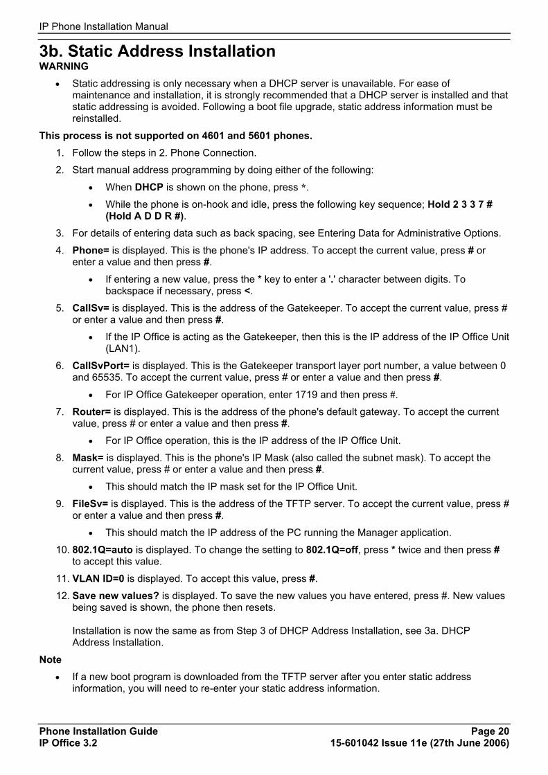
3b. Static Address Installation WARNING
• Static addressing is only necessary when a DHCP server is unavailable. For ease of maintenance and installation, it is strongly recommended that a DHCP server is installed and that static addressing is avoided. Following a boot file upgrade, static address information must be reinstalled.
This process is not supported on 4601 and 5601 phones. 1. Follow the steps in 2. Phone Connection.
2. Start manual address programming by doing either of the following:
• When DHCP is shown on the phone, press *.
• While the phone is on-hook and idle, press the following key sequence; Hold 2 3 3 7 # (Hold A D D R #).
3. For details of entering data such as back spacing, see Entering Data for Administrative Options.
4. Phone= is displayed. This is the phone's IP address. To accept the current value, press # or enter a value and then press #.
• If entering a new value, press the * key to enter a '.' character between digits. To backspace if necessary, press <.
5. CallSv= is displayed. This is the address of the Gatekeeper. To accept the current value, press # or enter a value and then press #.
• If the IP Office is acting as the Gatekeeper, then this is the IP address of the IP Office Unit (LAN1).
6. CallSvPort= is displayed. This is the Gatekeeper transport layer port number, a value between 0 and 65535. To accept the current value, press # or enter a value and then press #.
• For IP Office Gatekeeper operation, enter 1719 and then press #.
7. Router= is displayed. This is the address of the phone's default gateway. To accept the current value, press # or enter a value and then press #.
• For IP Office operation, this is the IP address of the IP Office Unit.
8. Mask= is displayed. This is the phone's IP Mask (also called the subnet mask). To accept the current value, press # or enter a value and then press #.
• This should match the IP mask set for the IP Office Unit.
9. FileSv= is displayed. This is the address of the TFTP server. To accept the current value, press # or enter a value and then press #.
• This should match the IP address of the PC running the Manager application.
10. 802.1Q=auto is displayed. To change the setting to 802.1Q=off, press * twice and then press # to accept this value.
11. VLAN ID=0 is displayed. To accept this value, press #.
12. Save new values? is displayed. To save the new values you have entered, press #. New values being saved is shown, the phone then resets. Installation is now the same as from Step 3 of DHCP Address Installation, see 3a. DHCP Address Installation.
Note
• If a new boot program is downloaded from the TFTP server after you enter static address information, you will need to re-enter your static address information.
Installation
Phone Installation Guide Page 21 IP Office 3.2 15-601042 Issue 11e (27th June 2006)
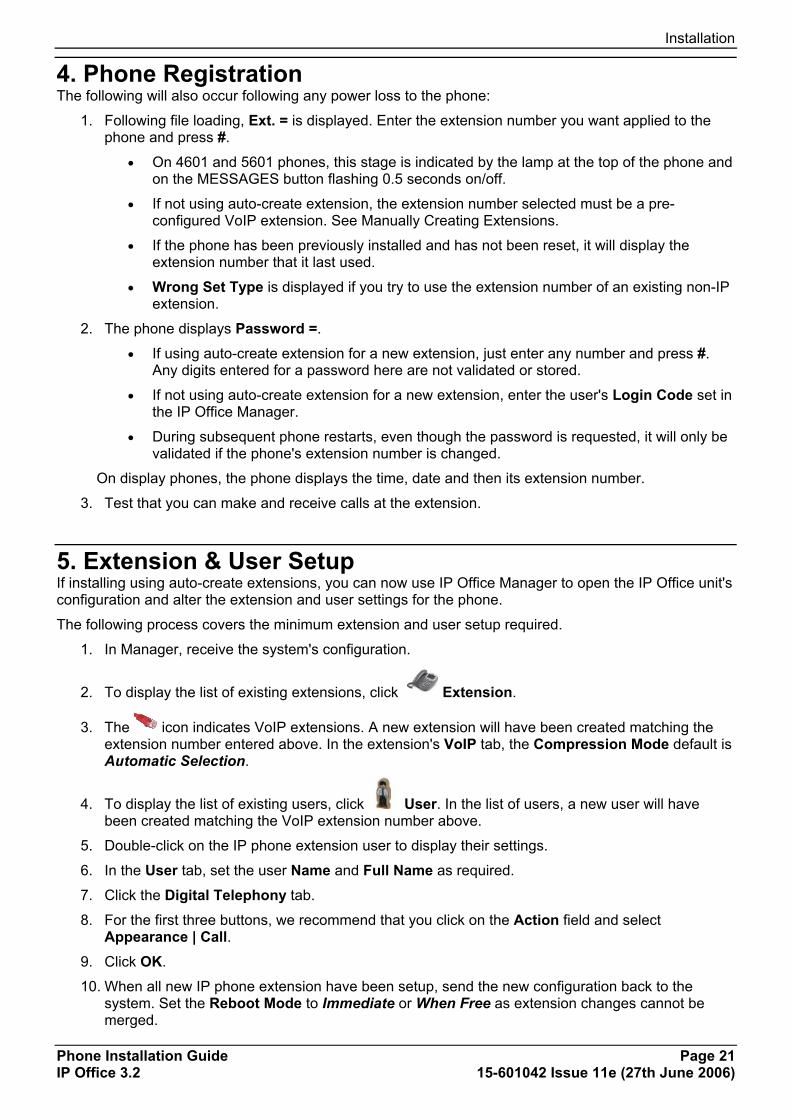
4. Phone Registration The following will also occur following any power loss to the phone:
1. Following file loading, Ext. = is displayed. Enter the extension number you want applied to the phone and press #.
• On 4601 and 5601 phones, this stage is indicated by the lamp at the top of the phone and on the MESSAGES button flashing 0.5 seconds on/off.
• If not using auto-create extension, the extension number selected must be a pre-configured VoIP extension. See Manually Creating Extensions.
• If the phone has been previously installed and has not been reset, it will display the extension number that it last used.
• Wrong Set Type is displayed if you try to use the extension number of an existing non-IP extension.
2. The phone displays Password =.
• If using auto-create extension for a new extension, just enter any number and press #. Any digits entered for a password here are not validated or stored.
• If not using auto-create extension for a new extension, enter the user's Login Code set in the IP Office Manager.
• During subsequent phone restarts, even though the password is requested, it will only be validated if the phone's extension number is changed.
On display phones, the phone displays the time, date and then its extension number.
3. Test that you can make and receive calls at the extension.
5. Extension & User Setup If installing using auto-create extensions, you can now use IP Office Manager to open the IP Office unit's configuration and alter the extension and user settings for the phone.
The following process covers the minimum extension and user setup required.
1. In Manager, receive the system's configuration.
2. To display the list of existing extensions, click Extension.
3. The icon indicates VoIP extensions. A new extension will have been created matching the extension number entered above. In the extension's VoIP tab, the Compression Mode default is Automatic Selection.
4. To display the list of existing users, click User. In the list of users, a new user will have been created matching the VoIP extension number above.
5. Double-click on the IP phone extension user to display their settings.
6. In the User tab, set the user Name and Full Name as required.
7. Click the Digital Telephony tab.
8. For the first three buttons, we recommend that you click on the Action field and select Appearance | Call.
9. Click OK.
10. When all new IP phone extension have been setup, send the new configuration back to the system. Set the Reboot Mode to Immediate or When Free as extension changes cannot be merged.
IP Phone Installation Manual
Phone Installation Guide Page 22 IP Office 3.2 15-601042 Issue 11e (27th June 2006)
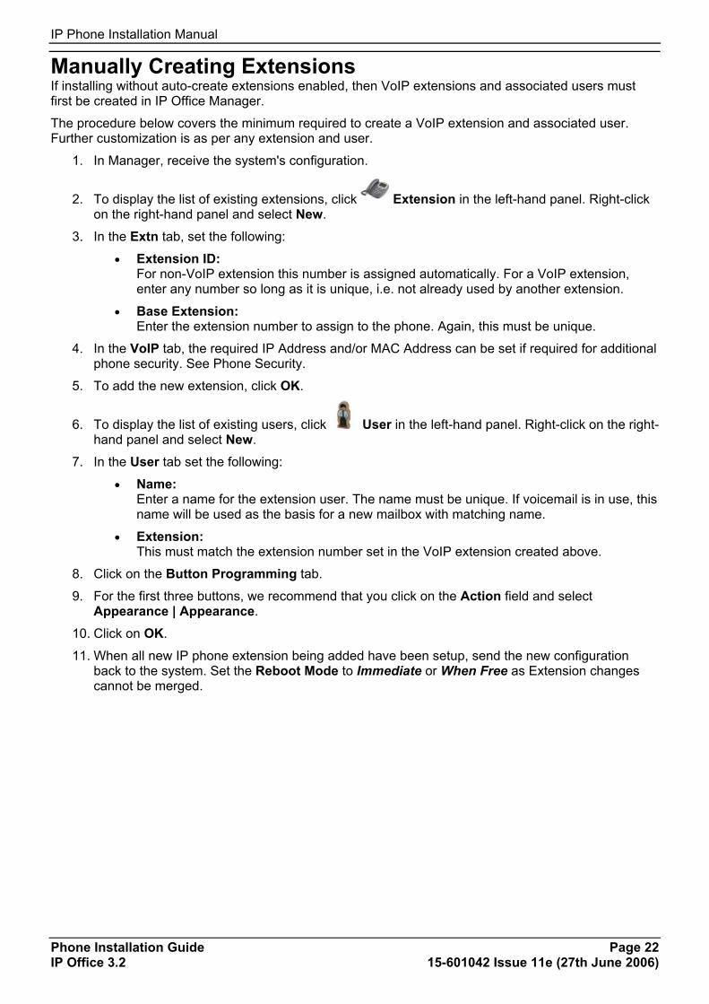
Manually Creating Extensions If installing without auto-create extensions enabled, then VoIP extensions and associated users must first be created in IP Office Manager.
The procedure below covers the minimum required to create a VoIP extension and associated user. Further customization is as per any extension and user.
1. In Manager, receive the system's configuration.
2. To display the list of existing extensions, click Extension in the left-hand panel. Right-click on the right-hand panel and select New.
3. In the Extn tab, set the following:
• Extension ID: For non-VoIP extension this number is assigned automatically. For a VoIP extension, enter any number so long as it is unique, i.e. not already used by another extension.
• Base Extension: Enter the extension number to assign to the phone. Again, this must be unique.
4. In the VoIP tab, the required IP Address and/or MAC Address can be set if required for additional phone security. See Phone Security.
5. To add the new extension, click OK.
6. To display the list of existing users, click User in the left-hand panel. Right-click on the right-hand panel and select New.
7. In the User tab set the following:
• Name: Enter a name for the extension user. The name must be unique. If voicemail is in use, this name will be used as the basis for a new mailbox with matching name.
• Extension: This must match the extension number set in the VoIP extension created above.
8. Click on the Button Programming tab.
9. For the first three buttons, we recommend that you click on the Action field and select Appearance | Appearance.
10. Click on OK.
11. When all new IP phone extension being added have been setup, send the new configuration back to the system. Set the Reboot Mode to Immediate or When Free as Extension changes cannot be merged.
Installation
Phone Installation Guide Page 23 IP Office 3.2 15-601042 Issue 11e (27th June 2006)
Phone Security There are a number of methods by which additional security can be implemented to ensure that an IP phone does not adopt the identity of another.
• Disable Auto-Create Extension Following installation, disabling Auto-Create Extn Enabled in the IP Office Manager System | Gatekeeper tab stops new IP devices from assigning themselves as new extensions.
• Restrict the IP Address or MAC Address Entering either of these values in the Extension's VoIP tab will restrict usage to that address or device. The MAC address of an IP phone is printed on a label on the base of the phone.
• Set a User Login Code If a user Login Code is set, then any other IP device trying to log on as that extension must also enter the correct login code.
Note • If a login code is set, the user can use hot desk to log off and log on elsewhere.
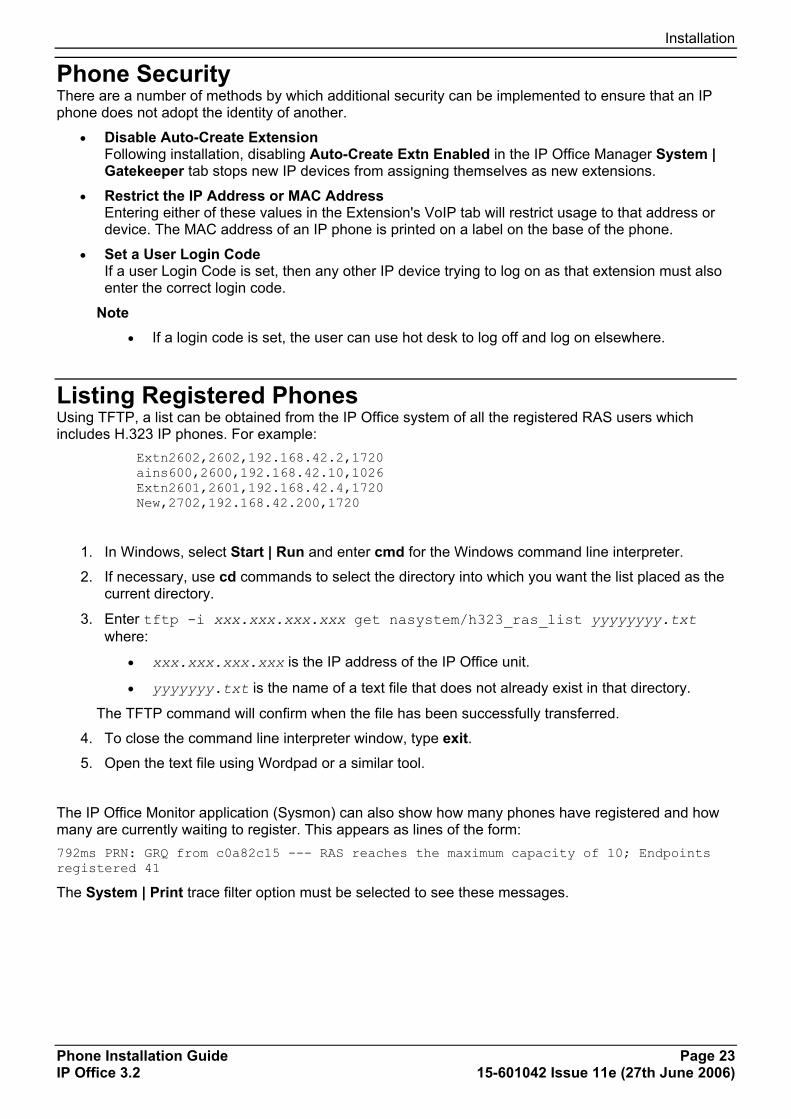
Listing Registered Phones Using TFTP, a list can be obtained from the IP Office system of all the registered RAS users which includes H.323 IP phones. For example:
Extn2602,2602,192.168.42.2,1720 ains600,2600,192.168.42.10,1026 Extn2601,2601,192.168.42.4,1720 New,2702,192.168.42.200,1720
1. In Windows, select Start | Run and enter cmd for the Windows command line interpreter.
2. If necessary, use cd commands to select the directory into which you want the list placed as the current directory.
3. Enter tftp -i xxx.xxx.xxx.xxx get nasystem/h323_ras_list yyyyyyyy.txt where:
• xxx.xxx.xxx.xxx is the IP address of the IP Office unit.
• yyyyyyy.txt is the name of a text file that does not already exist in that directory.
The TFTP command will confirm when the file has been successfully transferred.
4. To close the command line interpreter window, type exit. 5. Open the text file using Wordpad or a similar tool.
The IP Office Monitor application (Sysmon) can also show how many phones have registered and how many are currently waiting to register. This appears as lines of the form: 792ms PRN: GRQ from c0a82c15 --- RAS reaches the maximum capacity of 10; Endpoints registered 41
The System | Print trace filter option must be selected to see these messages.

Phone Installation Guide Page 25 IP Office 3.2 15-601042 Issue 11e (27th June 2006)
Static Administration Static Administration Options A number of settings can be altered through the phone after installation.
Note • Values assigned through static administration will not be changed by future upgrade scripts. They
will remain active for the IP phone until a new boot file is downloaded.
These procedures should only be used if you are using static address installation. Do not use these procedures if you are using DHCP.
• To set parameters for all H.323 IP phones on a system, you can edit the 46XXsettings.scr script file. See The 46XX Settings Script File.
Entering Data for Administrative Options This section describes how to enter data for the administrative options.
1. All local procedures are started by dialling Hold and then a sequence of up to 7 numbers followed by #.
2. After the Hold button is pressed, a 6-second timeout is in effect between button presses. If a valid button is not pressed within 6 seconds of the previous button, the collected digits are discarded and no administrative option is started.
3. Attempts to enter invalid data are rejected and the phone emits an error beep.
4. If a numeric digit is entered for a value or for a field of an IP address or subnet mask after only a zero has been entered, the new digit will replace the zero.
5. To go to the next step, press #.
6. To backspace within a field depends upon the phone type:
• 4601, 4602, 5601, 5602: Speaker key.
• 4606: Conference key.
• 4612 & 4624: Previous key. • 4610, 4620, 4625, 5610, 5620: Left-most key.

IP Phone Installation Manual
Phone Installation Guide Page 26 IP Office 3.2 15-601042 Issue 11e (27th June 2006)
QoS Option Settings Administering QoS options is not mandatory, but it is highly recommended. Use the following procedure to set Quality of Service (QoS) options.
1. While the phone is on-hook and idle, press the following sequence: Hold 7 6 7 # (Hold Q O S #). The current 802.1Q setting is shown.
2. L2 audio= is displayed. This is the phone's current 802.1 audio parameter. To accept the current value, press # or enter a value (between 0 and 7) and then press #.
3. L2 signaling= is displayed. This is the phones 802.1 signaling parameter. To accept the current value, press # or enter a value (between 0 and 7) and then press #.
4. L3 audio= is displayed. This is the phone's Differential Services audio parameter. To accept the current value, press # or enter a value (between 0 and 63) and then press #.
5. L3 signaling= is displayed. This is the phone's Differential Services signaling parameter. To accept the current value, press # or enter a value (between 0 and 63) and then press #.
6. If no new values were entered during this procedure, No new values is displayed. To end the procedure, press #.
7. If new values were entered during this procedure, Save new values? is displayed. To end the procedure or save the new values, press #. New values being saved is displayed and the phone returns to normal operation.
Secondary Ethernet (Hub)/IR Interface Enable/Disable Use the following procedure to enable or disable the hub interface found on some H.323 IP phones (usually marked with a symbol). The default for the hub interface is enabled.
The same procedure can also be used to enable or disable the IR port found on some H.323 IP phones, see Infrared Dialling.
1. While the phone is on-hook and idle, press the following sequence: Hold 4 6 8 # (Hold I N T #). PHY2= and the current setting is displayed. This is the PC connection LAN socket marked as on the phone.
2. Press 1 or 0 to enable or disable the hub interface respectively. To continue, press #. IR= is displayed and its current setting. This is the infrared (IR) port located on the front of some H.323 IP phones.
3. Press 1 or 0 to enable or disable the hub interface respectively. To continue, press #.
4. If you changed the setting, Save new values? is displayed. To end the procedure or save the new values, press #. If you press #, New values being saved is displayed and then returns to normal operation.
Phone Installation Guide Page 27 IP Office 3.2 15-601042 Issue 11e (27th June 2006)
Appendix A: Miscellaneous Error Messages The 4600 Series H.323 IP phones issue error messages in English only.
• Checksum error: Downloaded application file was not downloaded or saved correctly. The phone automatically resets and attempts to re-initialize.
• DHCP: CONFLICT: At least one of the IP addresses offered by the DHCP server conflicts with another address. Review DHCP server administration to identify duplicate IP addresses.
• Failed to set phone IP address: The IP phone was originally installed on one switch with Static Addressing and has subsequently been installed on another switch with an active DHCP server assigning dynamic IP addresses. Reset the phone.
• File too large cannot save file: The phone does not have sufficient room to store the downloaded file. Verify the proper filename is administered in the TFTP script file and that the proper application file is located in the appropriate location on the TFTP server.
• Hardware failure: Hardware failure prevented downloading of application file. Replace the phone.
• IP Address in use by another: The phone has detected an IP address conflict. Verify administration to identify duplicate IP addresses.
• No Ethernet: When first plugged in, the IP phone is unable to communicate with the Ethernet. Verify the connection to the Ethernet jack, verify the jack is Category 5, verify power is applied on the LAN to that jack, etc.
• No file server address: The TFTP server IP address in the IP phone's memory is all zeroes. Depending on the specific requirements of your network, this may not be an error. If appropriate, either administer the DHCP server with the proper address of the TFTP server, or administer the phone locally using the ADDR option.
• Resetting on URQ: Restarting following a reboot of the IP Office Unit.
• System busy: The resource being called upon should be checked for its availability. If it appears operational and properly linked to the network, verify addressing is accurate and a communication path exists in both directions between the phone and the resource.
• Timeout Error: Protocol timeout error. Retry. If failure continues, check network congestion, addresses, etc. to identify cause of timeout.
• TFTP Error: Request for file from TFTP server timed out. Check that IP Office Manager or the indicated TFTP source within the IP Office configuration are running and that the 4600 Series phone software files are available.
• Wrong Set Type: Another device is already assigned to the extension number of the IP phone.

IP Phone Installation Manual
Phone Installation Guide Page 28 IP Office 3.2 15-601042 Issue 11e (27th June 2006)
View Administrative Details You can use the following procedure to view a number of phone details. These are in addition to the other static address and local administration options which can also be used to review settings.
1. While the phone is on-hook and idle, press the following sequence: Hold 8 4 3 9 # (Hold V I E W #)
2. View settings is displayed.
• To display the set of details, press * at any time during viewing.
• To end the procedure and restore the user interface to its previous state, press # at any time during viewing.
3. The names and values displayed are:
• Model Shows the phones model number; for example, 4624D02A.
• Market Shows 1 for export or 0 for domestic (US).
• Phone SN Shows the phone's Serial Number.
• PWB SN Shows the phone's Printed Wiring Board Serial Number.
• PWB comcode Shows the PWB's comcode.
• MAC address Shows the phone's MAC address as paired hexadecimal numbers.
• filename1 Shows the name of the phone application file in the phone's memory.
• 10MBps Ethernet or 100Mbps Ethernet Shows the speed of the detected LAN connection.
• filename2 Shows the boot file name and level.
Note
• These are values from within the boot file loaded and not the actual file name.
Appendix A: Miscellaneous
Phone Installation Guide Page 29 IP Office 3.2 15-601042 Issue 11e (27th June 2006)
Reset System Values Use the following procedure to reset most of the phones values.
If a phone has been moved from another IP Office system, it will still retain values such as the DHCP and TFTP server address. To fully reset the phone, first go through a static installation setup and then reset the phone as below.
1. While the phone is on-hook and idle, press the following sequence: Hold 7 3 7 3 8 # (Hold R E S E T #). Reset values? is displayed.
2. To cancel this procedure and reset values to their defaults, press #.
WARNING As soon as you press #, all static information will be erased without any possibility of recovering the data. Whilst the system values are reset to their defaults, Resetting values is displayed.
3. Once the system values are reset, Restart phone? is displayed.
• To end the procedure without restarting the phone, press *. • To restart the phone, press #. The remainder of the procedure then depends on the status
of the boot and application files. See Restart Scenarios.
Self-Test Procedure 1. To start the IP phone self-test procedures, press the following sequence: Hold 8 3 7 8 # (Hold T
E S T #). The phone does the following:
• Each column of programmable button LED's is lit for half a second from left to right across the phone, in a repeating cycle. The Speaker/Mute LED and the message waiting LED are also lit in sequence.
• Buttons (other than #) generate a click if pressed.
• Phones with displays show Self test #=end for 1 second after self-test is started. Then a block character (all pixels on) is displayed in all display character locations for 5 seconds. Display of the block character is used to find bad display pixels.
One of the following is finally displayed:
• If self-test passes: Self test passed #=end
• If self-test fails: Self test failed #=end
2. To end the self-test, press #. The phone returns to normal operation.
IP Phone Installation Manual
Phone Installation Guide Page 30 IP Office 3.2 15-601042 Issue 11e (27th June 2006)
Site Specific Option Number The Site Specific Option Number (SSON) is used by H.323 IP phones to request information from a DHCP server. This number must be matched by a similarly numbered 'option' set on the DHCP server that define the various settings required by the phone.
WARNING • Do not perform this if using static addressing. Only perform this procedure if using DHCP
addressing and the DHCP option number has been changed from the normal default (176).
Setting the SSON on an IP Phone: 1. While the phone is on-hook and idle, press the following sequence: Mute 7 7 6 6 # (Mute S S O
N #). SSON= is displayed followed by the current value.
2. Enter the new setting. This must be a number between 128 and 255.
3. To cancel this procedure, press * or press # to save the new value.
Setting the SSON on IP Office: 1. In IP Office Manager, receive the system's current configuration.
2. Double-click System.
3. Click the Gatekeeper tab.
4. Set the SSON field to the required number.
5. Click OK.
6. Send the configuration back to the system. Select Immediate or When Free as the Reboot Mode.
Automatic Gain Control Automatic Gain Control (AGC) raises the volume when a caller is speaking quietly and lowers the volume when the caller is loud. AGC can be separately switched on or off for the phone handset, headset and speaker.
The AGC settings for all H.323 IP phones can also be set through the 46xxsetting.txt file, see The 46XX Settings Script File. On some phones it can also be switched on or off through the phone's user menus.
Switching automatic gain control on/off: 1. While the phone is on-hook and idle, press either Hold 2 4 2 # (Hold A G C #).
2. Handset AGC = is displayed followed by the current setting. Press the indicated key for the required setting (0 = off and 1 = on) and then press #.
3. Headset AGC = is displayed followed by the current setting. Press the indicated key for the required setting (0 = off and 1 = on) and then press #.
4. Speaker AGC = is displayed followed by the current setting. Press the indicated key for the required setting (0 = off and 1 = on) and then press #.
5. The phone should return to it normal idle state.
Phone Installation Guide Page 31 IP Office 3.2 15-601042 Issue 11e (27th June 2006)
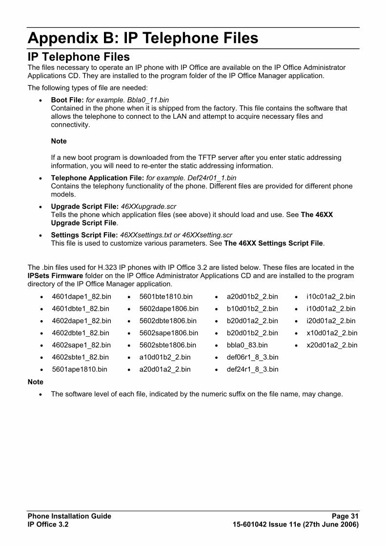
Appendix B: IP Telephone Files IP Telephone Files The files necessary to operate an IP phone with IP Office are available on the IP Office Administrator Applications CD. They are installed to the program folder of the IP Office Manager application.
The following types of file are needed:
• Boot File: for example. Bbla0_11.bin Contained in the phone when it is shipped from the factory. This file contains the software that allows the telephone to connect to the LAN and attempt to acquire necessary files and connectivity. Note If a new boot program is downloaded from the TFTP server after you enter static addressing information, you will need to re-enter the static addressing information.
• Telephone Application File: for example. Def24r01_1.bin Contains the telephony functionality of the phone. Different files are provided for different phone models.
• Upgrade Script File: 46XXupgrade.scr Tells the phone which application files (see above) it should load and use. See The 46XX Upgrade Script File.
• Settings Script File: 46XXsettings.txt or 46XXsetting.scr This file is used to customize various parameters. See The 46XX Settings Script File.
The .bin files used for H.323 IP phones with IP Office 3.2 are listed below. These files are located in the IPSets Firmware folder on the IP Office Administrator Applications CD and are installed to the program directory of the IP Office Manager application.
• 4601dape1_82.bin
• 4601dbte1_82.bin
• 4602dape1_82.bin
• 4602dbte1_82.bin
• 4602sape1_82.bin
• 4602sbte1_82.bin
• 5601ape1810.bin
• 5601bte1810.bin
• 5602dape1806.bin
• 5602dbte1806.bin
• 5602sape1806.bin
• 5602sbte1806.bin
• a10d01b2_2.bin
• a20d01a2_2.bin
• a20d01b2_2.bin
• b10d01b2_2.bin
• b20d01a2_2.bin
• b20d01b2_2.bin
• bbla0_83.bin
• def06r1_8_3.bin
• def24r1_8_3.bin
• i10c01a2_2.bin
• i10d01a2_2.bin
• i20d01a2_2.bin
• x10d01a2_2.bin
• x20d01a2_2.bin
Note • The software level of each file, indicated by the numeric suffix on the file name, may change.
IP Phone Installation Manual
Phone Installation Guide Page 32 IP Office 3.2 15-601042 Issue 11e (27th June 2006)
The 46XX Upgrade Script File Following any restart, each IP phone attempts to load the 46XXupgrade.scr file from the TFTP server. If not found, the phone will attempt to continue operation using its previous settings and software.
The 46XXupgrade.scr file contains a command script. The phone uses this script to check the names of the boot and application files it currently has loaded against those the script says it should have. Where there is a difference, the phone will request the new file from the TFTP server. If the phone loads a new file, it will restart again and recheck its files against the 46XXupgrade.scr script again.
Normally, no changes should be made to the 46XXupgrade.scr file, except possibly using a # to comment out either of the last two lines which refer to 46XXsettings.
The 46XX Settings Script File This file contains a range of settings used by H.323 IP phones and phone applications. These values may require editing to suit the customer installation. See 1a. Creating a 46xxsettings.txt File.
Note • Either a .scr or .txt file extension can be used. In both cases, the file is a plain text file.
The 46xxsettings.txt file can be edited using an ASCII text editor, for example Windows Notepad. To disable any setting, insert # in front of the line.
In addition to editing the existing contents of the 46xxsetting.txt file, additional lines can be added. Customizing the script will affect all H.323 IP phones using the TFTP server.
Note • Individual phones can be customized using static administration options on the phone. See Static
Administration Options. However, this is not recommended as static administration settings are lost following any upgrade of boot file software.
To modify the script, insert additional lines of the form SET parameter value where the possible parameters and values are listed below. For example, to switch the infrared port of all phones off, use SET IRSTAT 0.
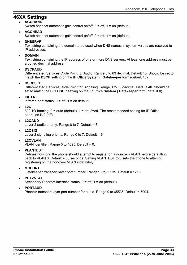
Appendix B: IP Telephone Files
Phone Installation Guide Page 33 IP Office 3.2 15-601042 Issue 11e (27th June 2006)
46XX Settings • AGCHAND
Switch handset automatic gain control on/off. 0 = off, 1 = on (default).
• AGCHEAD Switch headset automatic gain control on/off. 0 = off, 1 = on (default).
• DNSSRVR Text string containing the domain to be used when DNS names in system values are resolved to IP addresses.
• DOMAIN Text string containing the IP address of one or more DNS servers. At least one address must be a dotted decimal address.
• DSCPAUD Differentiated Services Code Point for Audio. Range 0 to 63 decimal. Default 40. Should be set to match the DSCP setting on the IP Office System | Gatekeeper form (default 46).
• DSCPSIG Differentiated Services Code Point for Signaling. Range 0 to 63 decimal. Default 40. Should be set to match the SIG DSCP setting on the IP Office System | Gatekeeper form (default 0).
• IRSTAT Infrared port status. 0 = off, 1 = on default.
• L2Q 802.1Q framing. 0 = auto (default), 1 = on, 2=off. The recommended setting for IP Office operation is 2 (off).
• L2QAUD Layer 2 audio priority. Range 0 to 7. Default = 6.
• L2QSIG Layer 2 signaling priority. Range 0 to 7. Default = 6.
• L2QVLAN VLAN identifier. Range 0 to 4095. Default = 0.
• VLANTEST Defines how long the phone should attempt to register on a non-zero VLAN before defaulting back to VLAN 0. Default = 60 seconds. Setting VLANTEST to 0 sets the phone to attempt registering on the non-zero VLAN indefinitely.
• MCPORT Gatekeeper transport layer port number. Ranger 0 to 65535. Default = 1719.
• PHY2STAT Secondary Ethernet interface status. 0 = off, 1 = on (default).
• PORTAUD Phone's transport layer port number for audio. Range 0 to 65535. Default = 5004.


Phone Installation Guide Page 35 IP Office 3.2 15-601042 Issue 11e (27th June 2006)
Appendix C: Scenarios for the Restart Process Restart Scenarios The sequence of the restart process depends on the status of the boot and application files on the TFTP server and those already downloaded to the phone. This appendix explains the different scenarios possible.
All of the following start-up processes involve the same initial steps as the phone negotiates with the DHCP and the TFTP server.
• After power is applied the phone displays Restarting….
• Initializing is then displayed.
• When either the application file (if there is one) or the boot code is uncompressed into RAM, Loading is displayed. Since this takes a while, asterisks, then periods, then asterisks are displayed on the second line to indicate that something is happening.
• When control is passed to the code in RAM, Starting is displayed.
• The phone detects and displays the speed of the Ethernet interface in Mbps (that is 10 or 100). The message No Ethernet means the LAN interface speed cannot be determined.
• The Ethernet speed indicated is the LAN interface speed for both the phone and any attached PC.
• DHCP is displayed whilst the phone obtains an IP address and other information from the LAN's DHCP server. The number of elapsed seconds is incremented until DHCP successfully completes.
• If the phone has been setup using static addressing (by pressing * when DHCP is shown), it will skip DHCP and use the static address settings it was given.
• Note that uploading a new boot file at any time erases all static address information.
• TFTP is displayed whilst waiting for a response from the TFTP server. 46XXUPGRADE.SCR is displayed whilst downloading the upgrade script TFTP server.
• TFTP Error: Timed Out is displayed if the phone cannot locate TFTP server or upgrade script file. If the phone has been previously installed it will continue with the existing files in its memory.
• After the upgrade script is loaded, the sequence depends on the status of the files currently held in the phones memory, compared to those listed in the upgrade script.
• Boot File Need Upgrading.
• No Application File or Application File Needs Upgrading.
• Correct Boot File and Application File Already Loaded.
IP Phone Installation Manual
Phone Installation Guide Page 36 IP Office 3.2 15-601042 Issue 11e (27th June 2006)
Boot File Needs Upgrading Having processed the upgrade script file, the software determines that the name of the boot code file in the phone does not match that in the upgrade script. The script specifies the name of the new file to load.
• The phone displays the file name and the number of kilobytes loaded.
• The phone displays Saving to flash while the new boot file is stored in its flash memory. The percentage of the file stored and the number of seconds that have elapsed are shown. This will usually take longer than it took to download the file.
• The phone displays Restarting as it prepares to reboot using the new boot file.
• The phone displays Initializing.
• While the new boot file is uncompressed into RAM, the phone displays Loading. Since this takes a while, asterisks, then periods, then asterisks are displayed on the second line to indicate that something is happening.
• When control is passed to the software that has just loaded, the phone displays Starting.
• The phone displays Clearing whilst the flash memory is erased in preparation for rewriting the code. The percentage of memory erased and number of elapsed seconds are also shown.
• Updating is displayed whilst the boot code is rewritten. The percentage of boot code rewritten and number of elapsed seconds are also shown.
• When the new boot code has been successfully written into the flash memory, the phone resets so that the status of the phone application files can be checked.
Continue with the next procedure; No Application File or Application File Needs Upgrading.
Appendix C: Scenarios for the Restart Process
Phone Installation Guide Page 37 IP Office 3.2 15-601042 Issue 11e (27th June 2006)
No Application File or Application File Needs Upgrading This happens with normal application file upgrades. Having processed the upgrade script file, the software determines that the name of the boot file in the phone is the correct version. It next determines that the name of the application file does not match that stored in the phone.
• The phone displays the required file name as it downloads the file from the TFTP server. It also displays the number of kilobytes downloaded.
• Saving to flash is displayed. The percentage of file stored and the number of seconds that have elapsed is also displayed. This will usually take longer than it took to download the file.
• The phone is reset so that the new system-specific application file can be executed.
• Continue with the next procedure; Correct Boot File and Application File Already Loaded.
Correct Boot File and Application File Already Loaded This happens with most normal restarts. Having processed the upgrade script file, the software determines that the name of the boot file in the phone and the phone application file match those specified in the upgrade script.
• System-specific registration with the switch is started. The phone requests the extension number it should use and the password.
• By default, the phone displays the last extension number it used. To accept, press #.
• Whilst a password request is shown, password verification is not performed except if the user changes the extension number.
• The password checked against is the user's Login Code stored in IP Office Manager.
• Upon completion of registration, a dial-tone is available on the phone.


Phone Installation Guide Page 39 IP Office 3.2 15-601042 Issue 11e (27th June 2006)
Appendix D: Infrared Dialling Infrared Dialling Several H.323 IP phones include an infrared (IR) port at the front of the phone. This includes the 4606, 4612, 4624 and 4620 phone. The port appears as a dark plastic window on the front edge of the phone, just below the normal dialling keys.
You can use the IR port in the following ways:
• Dial a Number to Start a Call: This can be done by beaming the contact information held in a personal organizer address book.
• Swap Text Files During a Call: If calling another IP phone extension that has an IR port, text files can be beamed between extensions.
When using infrared beaming, the following must be remembered:
• The device beaming or receiving must be IrDA compatible. This is the case for most computer and personal organizer IR ports.
• The range of transmission is typically a maximum of 5 feet (1.5 meters) and with a 5° degree spread (this is unlike IR devices used for remote controls which typically beam over a long range and much wider angle spread).
• For details of enabling and using IR beaming from your personal organizer or PC, refer to the manufacturer's information.
Note • Some personal organizers can be set to beam to modems and mobile phones which use
different transmission formats. The personal organizer may need to be set to beaming to another PC/personal organizer for dialling to work.
Important Note
• These features have been tested with several devices as indicated. However, this is not a commitment to continually test or support those devices against future levels of software.
IP Phone Installation Manual
Phone Installation Guide Page 40 IP Office 3.2 15-601042 Issue 11e (27th June 2006)
Enabling the IR Port By default, where fitted the IR port on H.323 IP phones is enabled. If necessary, it can be disabled.
1. With the phone on-hook and idle, press Hold 4 6 8 # (Hold I N T #). PHY2= and the current status is displayed. This is the setting for the phone's pass-through Ethernet port.
2. To continue, press #. IR=. The current status is displayed.
3. Change the status if required by following the displayed prompts and then press #. The phone will restart.
Dialling Phone Numbers You can use the IR port to receive phone numbers beamed from an IR enabled PC or pocket organizer device. Any device that can beam contacts in the VCard format (.vcf) can be used.
If you are unsure of the file format used by your IR device, you can try beaming a contact anyway. The display on the IP phone will show the name of the file it received. If that ends in .vcf, then the phone should dial the number in the VCard file.
You will need to remember the following:
• The phone will only dial the first phone number in the VCard file.
• If your IP Office system has been setup to need a prefix for external dialling, that prefix must be in the VCard phone number.
In addition to dialling the phone number digits, the following additional characters can be included in the phone number:
• m = Mute
• c = Conference
• h = Hold
• t = Transfer
• , (comma) = 2-second pause
The following sections contains examples of dialling contacts by beaming from various different devices.
Palm Organizer The following was tested using a Palm Vx and M505. The connection setting (Prefs | Connection) must be Ir to PC/Handheld.
1. To enter the address book, click onthe phone button or icon.
2. Locate the person or organization that you want to dial.
3. To go to Address View, click on the entry.
4. On the letters area of the graffiti pad, make a sweep from the bottom-left to the top-right. A set of icons should appear. Click on the beam icon. Alternatively, click on the menu icon and select Beam Address.

Appendix D: Infrared Dialling
Phone Installation Guide Page 41 IP Office 3.2 15-601042 Issue 11e (27th June 2006)
Windows Pocket PC The following was tested using a Compaq iPAQ Pocket PC:
1. In Contacts, select the entry you want to dial.
2. Click Tools and then select Beam Contact. The Pocket PC will search for and then display the IR enabled devices found. The IP phone should appear on the list.
3. Select the IP phone and the contact information will be beamed to it.
Beaming Files During a Call During a call between two IR enabled extensions on the same system, you can also beam files between IR devices at each end.
The types of file sendable and receivable will depend on those supported by the devices sending and receiving, as if they were face to face.
VCard files can be exchanged without being interpreted as a number to dial.
Palm Organizer The following was tested using a Palm Vx and M505.
1. Inform the caller that you want to beam them a file and to have their Palm positioned in front of their extensions IR port ready to receive.
2. Locate the file that you want to send.
3. On the letters area of the graffiti pad, make a sweep from the bottom-left to the top-right. A set of icons should appear. Click on the beam icon. Alternatively, click on the Menu icon and select the displayed Beam option. The phones should display the first eight characters and the file extension of the file being transferred.

Phone Installation Guide Page 43 IP Office 3.2 15-601042 Issue 11e (27th June 2006)
Appendix E: Alternate DHCP Setup Alternate DHCP Servers for Avaya IP Phone Installation
The recommended installation method for H.323 IP phones uses a DHCP server. When 5 or less H.323 IP phones are being supported, the DHCP can be performed by the IP Office Unit itself. However, if more than 5 H.323 IP phones are being supported, a separate DHCP server must be used.
This document outlines, as an example, the basic steps for using a Windows 2000 Server as the DHCP server for IP phone installation. However, the principles of defining a scope is applicable to most DHCP servers.
You will need the following information from the customer's network manager:
• The IP address range and subnet mask the H.323 IP phones should use.
• The IP Gateway address.
• The DNS domain name, DNS server address and the WINS server address.
• The DHCP lease time.
• The IP address of the IP Office unit.
• The IP address of the PC running Manager (this PC acts as a TFTP server for the H.323 IP phones during installation).
For information on LAN administration and configuration, see the 4600 Series IP Telephone LAN Administrator's Guide. Though written from the perspective of H.323 IP phones on Definity and MultiVantage systems, many aspects are applicable to IP Office systems.
Using Windows 2000 Server 1. Checking for DHCP
1. On the Windows 2000 Server, select Start | Program | Administrative Tools | Computer Management.
2. Under Services and Applications in the Computer Management Tree, locate DHCP.
3. If DHCP is not present then you need to install the DHCP components for Windows 2000. Refer to the Microsoft documentation.
IP Phone Installation Manual
Phone Installation Guide Page 44 IP Office 3.2 15-601042 Issue 11e (27th June 2006)
2. Windows 2000 DHCP Setup for H.323 IP Phones 2a. Creating the Scope A DHCP scope defines the IP addresses that the DHCP server can issue in response to DHCP requests. Different scopes may be defined for different types of devices.
1. Select Start | Programs | Administrative Tools | DHCP.
2. Right-click on the server and select New | Scope.
3. The scope creation wizard will be started, click Next. 4. Enter a name and comment for the scope and click Next. 5. Enter the address range to use, for example from 200.200.200.1 to 200.200.200.15 (remember
the host part cannot be 0).
6. Enter the subnet mask as either the number of bits used or the actual mask, for example 24 is the same as 255.255.255.0 and click Next.
7. You can specify addresses to be excluded. You can do this either entering a range (e.g. 200.200.200.5 to 200.200.200.7) and clicking Add, or entering a single address and clicking Add.
Note • You should exclude the IP Office from this range, as the DHCP Options in the IP Office
should be disabled. This is only a recommendation. You can also accomplish this by leaving available addresses outside of the scopes range.
8. Click Next. 9. You can now set the lease time for addresses. If set too large, addresses used by devices no
longer attached will not expire and be available for reuse in a reasonable time. This reduces the number of addresses available for new devices. If set too short, it will generate unnecessary traffic for address renewals. The default is 8 days. Click Next.
10. The wizard gives the option to configure the most common DHCP options. Select Yes and then click Next.
11. Enter the address of the gateway and click Add. You can enter several. When all are entered, click Next.
12. Enter the DNS domain (e.g. savilltech.com) and the DNS server addresses. Click Next. 13. Enter the WINS server addresses and click Add and then click Next. 14. You will then be asked if you wish to activate the scope. Select No and then click Next. 15. Click Finish.
The new scope will now be listed and the status is Inactive.
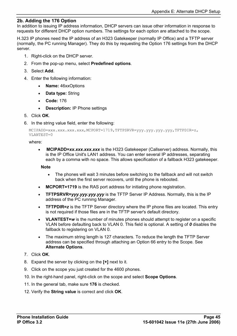
Appendix E: Alternate DHCP Setup
Phone Installation Guide Page 45 IP Office 3.2 15-601042 Issue 11e (27th June 2006)
2b. Adding the 176 Option In addition to issuing IP address information, DHCP servers can issue other information in response to requests for different DHCP option numbers. The settings for each option are attached to the scope.
H.323 IP phones need the IP address of an H323 Gatekeeper (normally IP Office) and a TFTP server (normally, the PC running Manager). They do this by requesting the Option 176 settings from the DHCP server.
1. Right-click on the DHCP server.
2. From the pop-up menu, select Predefined options.
3. Select Add.
4. Enter the following information:
• Name: 46xxOptions
• Data type: String
• Code: 176
• Description: IP Phone settings
5. Click OK.
6. In the string value field, enter the following: MCIPADD=xxx.xxx.xxx.xxx,MCPORT=1719,TFTPSRVR=yyy.yyy.yyy.yyy,TFTPDIR=z, VLANTEST=0
where:
• MCIPADD=xx.xxx.xxx.xxx is the H323 Gatekeeper (Callserver) address. Normally, this is the IP Office Unit's LAN1 address. You can enter several IP addresses, separating each by a comma with no space. This allows specification of a fallback H323 gatekeeper.
Note • The phones will wait 3 minutes before switching to the fallback and will not switch
back when the first server recovers, until the phone is rebooted.
• MCPORT=1719 is the RAS port address for initiating phone registration.
• TFTPSRVR=yyy.yyy.yyy.yyy is the TFTP Server IP Address. Normally, this is the IP address of the PC running Manager.
• TFTPDIR=z is the TFTP Server directory where the IP phone files are located. This entry is not required if those files are in the TFTP server's default directory.
• VLANTEST=w is the number of minutes phones should attempt to register on a specific VLAN before defaulting back to VLAN 0. This field is optional. A setting of 0 disables the fallback to registering on VLAN 0.
• The maximum string length is 127 characters. To reduce the length the TFTP Server address can be specified through attaching an Option 66 entry to the Scope. See Alternate Options.
7. Click OK.
8. Expand the server by clicking on the [+] next to it.
9. Click on the scope you just created for the 4600 phones.
10. In the right-hand panel, right-click on the scope and select Scope Options.
11. In the general tab, make sure 176 is checked.
12. Verify the String value is correct and click OK.
IP Phone Installation Manual
Phone Installation Guide Page 46 IP Office 3.2 15-601042 Issue 11e (27th June 2006)
2c. Activate the Scope The scope can be manually activated by right clicking on the scope, select All Tasks and select Activate. The activation is immediate.
You should now be able to start installing H.323 IP phones using DHCP. Ensure that Manager is running on the PC specified as the TFTP server.
Alternate Options In this document, all IP phone information is issued through the Scope and the Option 176 settings. Depending on the DHCP server, other options may have to be used within the scope.
• Option 6: DNS Server Address On the Windows 2000 DHCP server this is set through the scope. Other DHCP servers may allow or require it to be set through Option 6 with multiple addresses separated by a comma and no spaces. At least one address must be a dot decimal IP address.
• Option 15: DNS Domain Name On the Windows 2000 DHCP server this is set through the scope. Other DHCP servers may allow or require it to be set through Option 15. This option is necessary if the TFTP server is indicated by name rather than address (not supported on Windows DHCP).
• Option 66: TFTP Server Name Allows the specifying of the TFTP server address. Multiple addresses can be entered with each address separated by a comma and no spaces. Microsoft DHCP servers only support dot decimal IP addresses.
Note
• The H.323 IP phones, any Option 66 settings will be overridden by any TFTP entry in Option 176. Using Option 66 as part of the Scope is useful if alternate Gatekeeper addresses are required in the Option 176 settings whilst keeping within the 127 character limit.
Phone Installation Guide Page 47 IP Office 3.2 15-601042 Issue 11e (27th June 2006)
Appendix F: WML Operation WML Server Setup The 4610SW, 4620, 4620SW, 5610SW, 5620 and 5620 phones can act as WAP (Wireless Access Protocol) browsers. This allows them to view WML (Wireless Markup Language) pages. WML is a page coding language similar to HTML but intended for phone devices with small screens and no full keyboard.
To do WAP browsing, the phones need to be configured to access a home page. That home page can contain links and information appropriate to the customer installation.
This section looks at the setting up and configuration of a simple test system. The aim is to introduce the basic principles of WAP browsing operation.
What WML is Supported The phones are WML 1.2 compliant WAP browsers. However, they do not support all WML 1.2 tags.
For details of those WML 1.2 tags supported, refer to the 4600 Series IP Telephone LAN Administrator's Guide.
WTAI (Wireless Telephony Application Interface) links are supported to allow numbers embedded in WML pages to be dialed from phones.
IP Phone Installation Manual
Phone Installation Guide Page 48 IP Office 3.2 15-601042 Issue 11e (27th June 2006)
Testing WML Browsing Using Xitami 1. Introduction Xitami is a small and simple web server application. It is used here to configure one of our LAN PC's as a web server able to provide .wml pages is response to requests from an IP phone.
• Web Server PC: Any Windows PC on the IP Office LAN. Ideally this PC should have a fixed IP address.
• Xitami Server Software: Xitami can be obtained from http://www.imatix.com. A copy is available on the IP Office Documentation CD.
• Sample WML Pages: A number of sample pages are provided on the IP Office Documentation CD. They can also be downloaded from http://support.avaya.com.
2. Installing the Web Server For this test we used a web server called Xitami. It is a simple, small and flexible web server for use on Windows based PC's.
1. On the server PC, run Xitami.exe to start installation of the web server.
2. Accept the various defaults.
3. When asked for a User Name and Password, note the details entered.
4. When finished, select Run. The Xitami server appears as an icon.
5. To display the web servers basic properties, double-click . Note the IP addresses.
6. To close the window without stopping the web server, click Close.
7. Open the PC's web browser and enter http://<server IP address>. You should see the default Xitami web pages. If there are other PC's on the IP Office LAN they should also be able to browse the web server's IP address.
3. Configuring the Xitami Web Server for WAP Basic web browsing consist of requests to the web server for .htm and .html text pages and .gif and .jpg images which are then displayed by a browser program. WAP browsing uses different file types, wml for text and .wbmp for images.
The web server needs to be configured to recognize those file types, and several others, as files that might be requested by a WAP browser program. This is done by adding what many web servers refer to as MIME types.
1. On the web server PC, open the folder C:\Xitami. 2. Using a plain text editor such as Notepad or WordPad, open the file Xitami.cfg.
3. Scroll down the file to the section [MIME]. You will see that it is a list of settings for different text, image and application files types.
4. Scroll the end of the file and add the following new set of MIME type for files that are supported by H.323 IP phones with a WAP browser.
# WAP MIME types wml=text/vnd.wap.wml
5. Save the file.
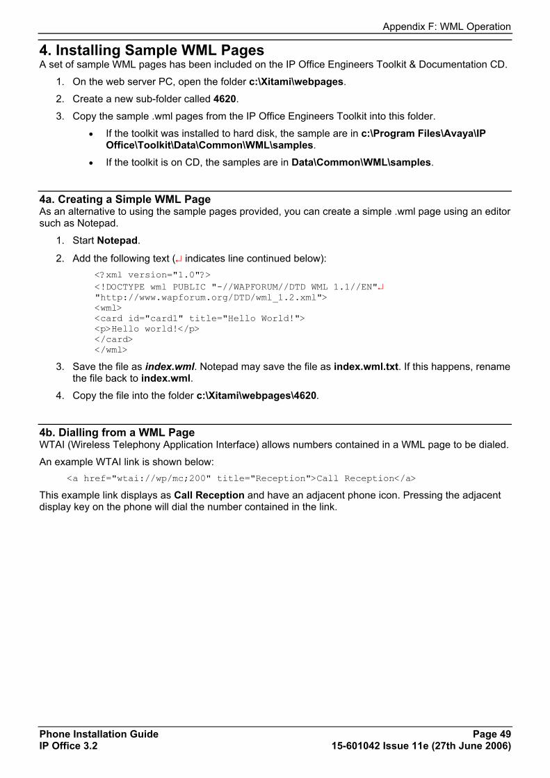
Appendix F: WML Operation
Phone Installation Guide Page 49 IP Office 3.2 15-601042 Issue 11e (27th June 2006)
4. Installing Sample WML Pages A set of sample WML pages has been included on the IP Office Engineers Toolkit & Documentation CD.
1. On the web server PC, open the folder c:\Xitami\webpages.
2. Create a new sub-folder called 4620.
3. Copy the sample .wml pages from the IP Office Engineers Toolkit into this folder.
• If the toolkit was installed to hard disk, the sample are in c:\Program Files\Avaya\IP Office\Toolkit\Data\Common\WML\samples.
• If the toolkit is on CD, the samples are in Data\Common\WML\samples.
4a. Creating a Simple WML Page As an alternative to using the sample pages provided, you can create a simple .wml page using an editor such as Notepad.
1. Start Notepad.
2. Add the following text (↵ indicates line continued below): <?xml version="1.0"?> <!DOCTYPE wml PUBLIC "-//WAPFORUM//DTD WML 1.1//EN"↵ "http://www.wapforum.org/DTD/wml_1.2.xml"> <wml> <card id="card1" title="Hello World!"> <p>Hello world!</p> </card> </wml>
3. Save the file as index.wml. Notepad may save the file as index.wml.txt. If this happens, rename the file back to index.wml.
4. Copy the file into the folder c:\Xitami\webpages\4620.
4b. Dialling from a WML Page WTAI (Wireless Telephony Application Interface) allows numbers contained in a WML page to be dialed.
An example WTAI link is shown below: <a href="wtai://wp/mc;200" title="Reception">Call Reception</a>
This example link displays as Call Reception and have an adjacent phone icon. Pressing the adjacent display key on the phone will dial the number contained in the link.

IP Phone Installation Manual
Phone Installation Guide Page 50 IP Office 3.2 15-601042 Issue 11e (27th June 2006)
Setting the Home Page WAP capable H.323 IP phones display a key option labeled Web when setup with a home page (press PHONE/EXIT if in any other menu).
To access the home page, press the adjacent display key. The home page is set by editing the 46XXsetting.scr file found in the IP Office Manager applications program folder.
Important • This must be the same Manager PC as used for IP phone installation. This will be the PC set as
the TFTP Server IP address in the IP Office configuration, i.e. the address from which the H.323 IP phones request files when restarted.
1. Open the Manager application folder (c:\Program Files\Avaya\IP Office\Manager). 2. Locate the file 46XXsettings.scr. 3. The file cannot be edited as is, since the .scr extension is associated by Windows with screen
savers. Rename the 46XXsettings.scr file to 46XXsettings.txt. 4. Double-click on 46XXsettings.txt. The file will open in Notepad.
The section relating to 4620 WML browsing is towards the end of the file. It will look similar to the following: ################ SETTINGS FOR AVAYA 4620 IP PHONE ################### ## 4620 Web Launch page in WML - Default: Avaya hosted SET WMLHOME http://192.168.42.200/4620/index.wml ## The Proxy server used for your LAN - IP address or human readable name (check your browser settings). # SET WMLPROXY nj.proxy.avaya.com ## The http proxy server port (check your browser settings). SET WMLPORT 8000 ## Exceptions: You must use an IP address not a DNS name # Example: SET WMLEXCEPT 111.222.333.444 ## Text coding for the web pages defaulted to ASCII. SET WMLCODING ASCII ##################### END OF AVAYA 4620 IP PHONE ####################
5. Edit SET WMLHOME to be the address of the sample index.wml file on the web server. In this example; http://192.168.42.200/4620/index.wml.
• If DNS is being used to access the web server by IP name, the SET DOMAIN and SET DNSSRVR lines at the start of the 46XXsettings.scr file should be edited to match the LAN settings. The preceding #'s should be removed from the lines to make them active.
6. Close and save the file.
7. Rename the file back to 46XXsettings.scr. The settings will not take effect until after the phones have restarted, whilst Manager is running.
8. Start Manager. 9. Select View | TFTP log. This will allow you to see the phones request and download the
46XXsettings.scr file.
10. Either:
• Select File | Advanced | Reboot. Select the system to reboot and enter the system password.
OR
• Manually unplug and then reattach the LAN cable from the phone.
Once the phone has restarted it should display Web as one of the screen option.
12. Press Web.
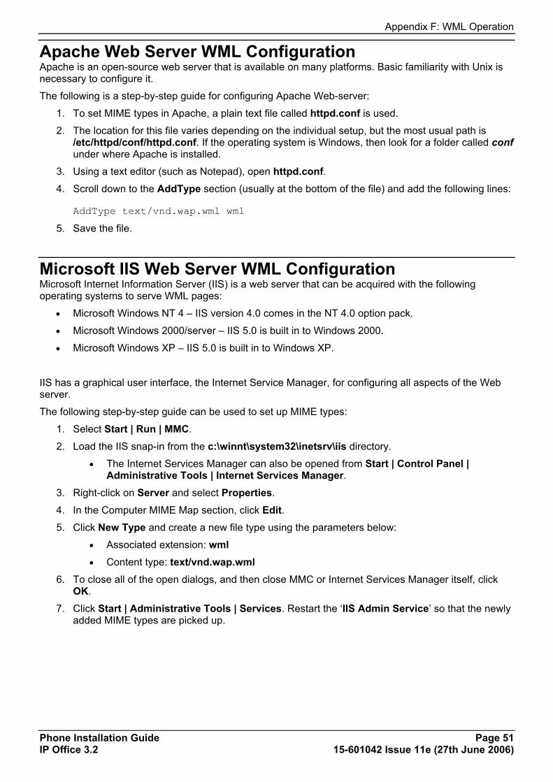
Appendix F: WML Operation
Phone Installation Guide Page 51 IP Office 3.2 15-601042 Issue 11e (27th June 2006)
Apache Web Server WML Configuration Apache is an open-source web server that is available on many platforms. Basic familiarity with Unix is necessary to configure it.
The following is a step-by-step guide for configuring Apache Web-server:
1. To set MIME types in Apache, a plain text file called httpd.conf is used.
2. The location for this file varies depending on the individual setup, but the most usual path is /etc/httpd/conf/httpd.conf. If the operating system is Windows, then look for a folder called conf under where Apache is installed.
3. Using a text editor (such as Notepad), open httpd.conf. 4. Scroll down to the AddType section (usually at the bottom of the file) and add the following lines:
AddType text/vnd.wap.wml wml
5. Save the file.
Microsoft IIS Web Server WML Configuration Microsoft Internet Information Server (IIS) is a web server that can be acquired with the following operating systems to serve WML pages:
• Microsoft Windows NT 4 – IIS version 4.0 comes in the NT 4.0 option pack.
• Microsoft Windows 2000/server – IIS 5.0 is built in to Windows 2000.
• Microsoft Windows XP – IIS 5.0 is built in to Windows XP.
IIS has a graphical user interface, the Internet Service Manager, for configuring all aspects of the Web server.
The following step-by-step guide can be used to set up MIME types:
1. Select Start | Run | MMC.
2. Load the IIS snap-in from the c:\winnt\system32\inetsrv\iis directory.
• The Internet Services Manager can also be opened from Start | Control Panel | Administrative Tools | Internet Services Manager.
3. Right-click on Server and select Properties.
4. In the Computer MIME Map section, click Edit. 5. Click New Type and create a new file type using the parameters below:
• Associated extension: wml • Content type: text/vnd.wap.wml
6. To close all of the open dialogs, and then close MMC or Internet Services Manager itself, click OK.
7. Click Start | Administrative Tools | Services. Restart the ‘IIS Admin Service’ so that the newly added MIME types are picked up.

IP Phone Installation Manual
Phone Installation Guide Page 52 IP Office 3.2 15-601042 Issue 11e (27th June 2006)
Open URL Entry This document provides sample WML code on how to develop WML pages implementing a text box-based go to a URL function. This code allows a user to enter a URL into a text entry area and link to that site.
Please note that these are examples, not an exhaustive list. All WML code is presented in italics.
Case 1. Input Box Followed by an Anchor Tag Description: The user enters a URL into the text entry box and clicks on the URL to retrieve it.
<input name="url" title="Name" /> <anchor title="get it"> Go Get It <go method="get" href="$(url)"> </go> </anchor>
Case 2. Input Box Followed by an A Tag <input name="url" title="Name" /> <a href="$(url)">Go Get It</a>
Case 3. Input Box Followed by a Submit Button <input name="url" title="Name" /> <do type="submit" name ="submit" label = "Submit"> <go method="get" href="$(url)"> </go> </do>
Case 4. Input Box Followed by an Anchor Tag Where the Anchor Tag Already Displays HTTP:// This method displays http so that the user only has to type in the URL at the end of http://.
<input name="url" title="Name" value="http://" /> <anchor title="GET"> Go Get it <go method="get" href="$(url)"> </go> </anchor>

Phone Installation Guide Page 53 IP Office 3.2 15-601042 Issue 11e (27th June 2006)
Appendix G: 3616/3620/3626 Installation 3616/3620/3626 Spectralink Installation This section contains information on the installation and configuration of the Avaya 3616/3620/3626 wireless phones on an IP Office Unit.
Information is routed from these phones to IP Office via an Avaya Voice Priority Processor (AVPP). The AVPP uses Spectralink Voice Priority (SVP) as the Quality of Service (QoS) mechanism. SVP gives preference to voice packets on the wireless medium, increasing the probability that all voice packets are transmitted efficiently. The use of SVP requires the wireless Access Point to be SVP compatible.
Use of the 3616, 3620 and 3626 phones via an AVPP is supported on the IP Office IP403, IP406 (V1 and V2) and IP412 units. The Small Office Edition unit is able to support a built-in wireless access point. However, this does not provide Quality of Service (QoS) support.
Related Documents The setup for the 3616/3620/3626 wireless phones also requires the configuration of the AVPP and the individual wireless phones. These instructions are provided in the IP Office Wireless Installation and Configuration User Guide.
Access Points Supplied by either Avaya or third party vendors, Access Points provide the connection between the wired Ethernet LAN and the wireless (802.11b) LAN. Access Points must be positioned in all areas where wireless phones will be used. The number and placement of Access Points will affect the coverage area and capacity of the wireless system. Typically, the requirements for use of wireless phones are similar to that of wireless data devices.
The wireless phones must connect to access points that use AVPP. For a complete list of access points supported, go to: www.spectralink.com/consumer/resources/wifi_compatibility.jsp


Phone Installation Guide Page 55 IP Office 3.2 15-601042 Issue 11e (27th June 2006)
Index 1 176 option ................................................................43 4 4601/5601................................................................18 A access point .........................................................5, 53 administrative options ........................................25, 28 AGC .........................................................................30 Apache.....................................................................51 application file ..........................................................37 AVPP ...................................................................5, 53 B beaming files............................................................41 boot ....................................................................36, 37 C cabling........................................................................9 cat 5 ...........................................................................6 configuration
file source ...........................................................14 Microsoft IIS........................................................51
D DHCP
alternate..............................................................43 connection ..........................................................19 installation.......................................................4, 19 introduction ...........................................................1 preparation..........................................................17 windows ..............................................................43 wireless.................................................................5
dialling......................................................................40 DNS .........................................................................46 E error messages........................................................27 extension..................................................................21 extensions................................................................22 G gatekeeper .......................................................4, 6, 17 H home page...............................................................50 I installation
4601/5601...........................................................18 DHCP..............................................................1, 19 large......................................................................4 requirements.........................................................6 small .....................................................................3 static address......................................................20 wireless.................................................................5
IP address..................................................................9 IR port ................................................................26, 40 L license key .................................................................6 N network assessment ..................................................7
P Palm.........................................................................41 phone
3616/3620/3626..................................................53 4601/5601 installation.........................................18 connection ..........................................................19 dialling.................................................................40 infrared dialling ...................................................39 registration ....................................................21, 23 security................................................................23
power over ethernet .................................................11 power supply........................................................6, 11 preparation...............................................................17 Q QoS......................................................................8, 26 R registration ...............................................................21 reset sytem values...................................................29 restart .......................................................................35 S script file...................................................................32 self test.....................................................................29 site specific option number ......................................30 Spectralink ...............................................................53 static address
installation...........................................................20 T TFTP
application...........................................................15 control unit memory card ....................................14 installation.............................................................6 introduction .........................................................13 preparation..........................................................17 wireless.................................................................5
txt file........................................................................18 U upgrading
application file .....................................................37 boot file ...............................................................36
URL..........................................................................52 user ....................................................................10, 21 V voice compression
channels ...............................................................8 installation.............................................................6
VoIP ...........................................................................9 W Windows
2000....................................................................43 pocket PC ...........................................................40
wireless installation....................................................5 WML............................................................ 47, 48, 51 X Xitami .......................................................................48
IP Phone Installation Manual
Phone Installation Guide Page 56 IP Office 3.2 15-601042 Issue 11e (27th June 2006)
Performance figures and data quoted in this document are typical, and must be specifically confirmed in writing by Avaya before they become applicable to any particular order or contract. The company
reserves the right to make alterations or amendments to the detailed specifications at its discretion. The publication of information in this document does not imply freedom from patent or other protective rights
of Avaya or others.
Intellectual property related to this product (including trademarks) and registered to Lucent Technologies have been transferred or licensed to Avaya.
All trademarks identified by the ® or ™ are registered trademarks or trademarks, respectively, of Avaya Inc. All other trademarks are the property of their respective owners.
This document contains proprietary information of Avaya and is not to be disclosed or used except in accordance with applicable agreements.
Any comments or suggestions regarding this document should be sent to "[email protected]".
© 2006 Avaya Inc. All rights reserved.
Avaya Unit 1, Sterling Court
15 - 21 Mundells Welwyn Garden City
Hertfordshire AL7 1LZ England
Tel: +44 (0) 1707 392200 Fax: +44 (0) 1707 376933
Web: http://www.avaya.com/ipoffice/knowledgebase