Embed Size (px)
Citation preview
®
VALVES • VESSELS • SYSTEMS • CONTROLS
PhillipsREFRIGERATION
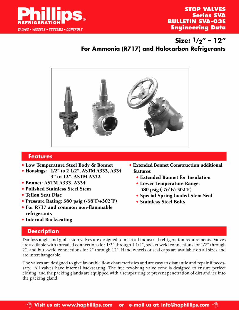
Size: 1/2” – 12”For Ammonia (R717) and Halocarbon Refrigerants
Description
• Low Temperature Steel Body & Bonnet• Housings: 1/2” to 2 1/2”, ASTM A333, A334
3” to 12”, ASTM A352• Bonnet: ASTM A333, A334• Polished Stainless Steel Stem• Teflon Seat Disc• Pressure Rating: 580 psig (-58˚F/+302˚F)• For R717 and common non-flammable
refrigerants• Internal Backseating
Features
STOP VALVESSeries SVA
BULLETIN SVA-03EEngineering Data
Danfoss angle and globe stop valves are designed to meet all industrial refrigeration requirements. Valvesare available with threaded connections for 1/2” through 1 1/4”, socket weld connections for 1/2” through2”, and butt-weld connections for 2” through 12”. Hand wheels or seal caps are available on all sizes andare interchangeable.
The valves are designed to give favorable flow characteristics and are easy to dismantle and repair if neces-sary. All valves have internal backseating. The free revolving valve cone is designed to ensure perfectclosing, and the packing glands are equipped with a scraper ring to prevent penetration of dirt and ice intothe packing gland.
• Extended Bonnet Construction additionalfeatures:• Extended Bonnet for Insulation• Lower Temperature Range:
580 psig (-76˚F/+302˚F)• Special Spring-loaded Stem Seal• Stainless Steel Bolts
Visit us at: www.haphillips.com or e-mail us at: [email protected]� �
DesignConnections
• Butt-weld (ANSI B 36.10 Schedule 80), 1/2” —1 1/2”• Butt-weld (ANSI B 36.10 Schedule 40), 2” —12”• Socket Weld, 1/2”—2”• FPT Female Pipe Thread, NPT (ANSI/ASME B 1.20.1), 1/2”—1 1/4”
HousingMade of special, cold resistant steel approved for low temperature operations.
Valve ConeThe valve cone can be turned on the stem, thus there will be no friction between the cone and the seatwhen the valve is opened and closed. The Teflon seat disc provides perfect sealing at a minimumclosing torque.
StemMade of polished stainless steel, ideal for O-ring sealing.
Packing GlandStandard Construction (ST):The standard packing gland ensures a perfect tightness in the range: -58/+302oF (-50/+150oC).The packing glands are equipped with a scraper ring to prevent penetration of dirt and ice intothe packing gland.
Extended Bonnet Construction (-EX), Low Temperature Range Version:This comprises a spring-loaded seal packing gland, which ensures a perfect tightness in the range:-76/+302oF (-60/+150oC). The packing glands are equipped with a scraper ring to prevent penetra-tion of dirt and ice into the packing gland.
InstallationIt is recommended that the valves be installed in the direction of flow indicated by the arrow on thevalve body. The valve can be installed in the opposite direction, but this slightly reduces the C
v-value
(kv-value).
The valve is designed to withstand high internal pressure. However, the piping system in generalshould be designed to avoid liquid traps and reduce the risk of hydraulic pressure caused by thermalexpansion.
For further information, refer to the installation instructions for SVA stop valves.
page 2
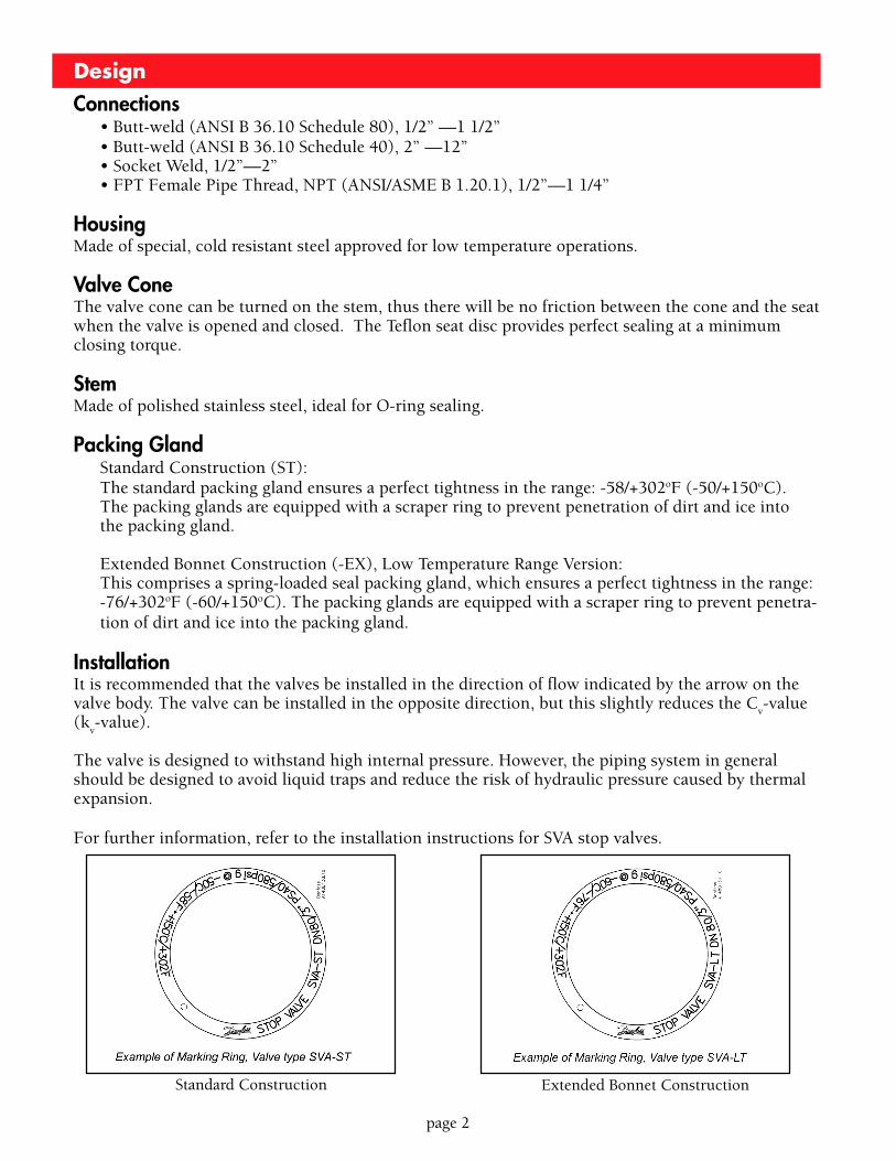
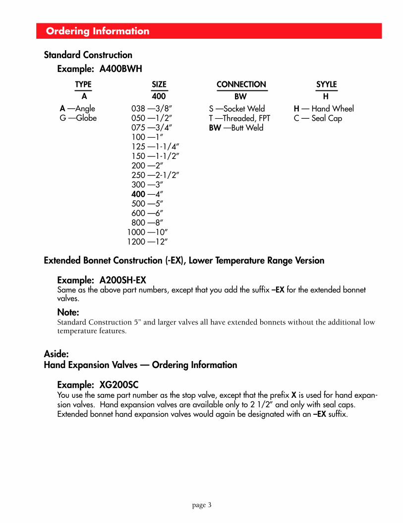
Standard Construction Extended Bonnet Construction
page 3
Standard ConstructionExample: A400BWH
AA —AngleG —Globe
400 038 —3/8” 050 —1/2” 075 —3/4” 100 —1” 125 —1-1/4” 150 —1-1/2” 200 —2” 250 —2-1/2” 300 —3” 400 —4” 500 —5” 600 —6” 800 —8”1000 —10”1200 —12”
BWS —Socket WeldT —Threaded, FPTBW —Butt Weld
HH — Hand WheelC — Seal Cap
Extended Bonnet Construction (-EX), Lower Temperature Range Version
Example: A200SH-EXSame as the above part numbers, except that you add the suffix –EX for the extended bonnetvalves.
Note:Standard Construction 5” and larger valves all have extended bonnets without the additional lowtemperature features.
Aside:Hand Expansion Valves — Ordering Information
Example: XG200SCYou use the same part number as the stop valve, except that the prefix X is used for hand expan-sion valves. Hand expansion valves are available only to 2 1/2” and only with seal caps.Extended bonnet hand expansion valves would again be designated with an –EX suffix.
Ordering Information
TYPE SIZE CONNECTION SYYLE
page 4
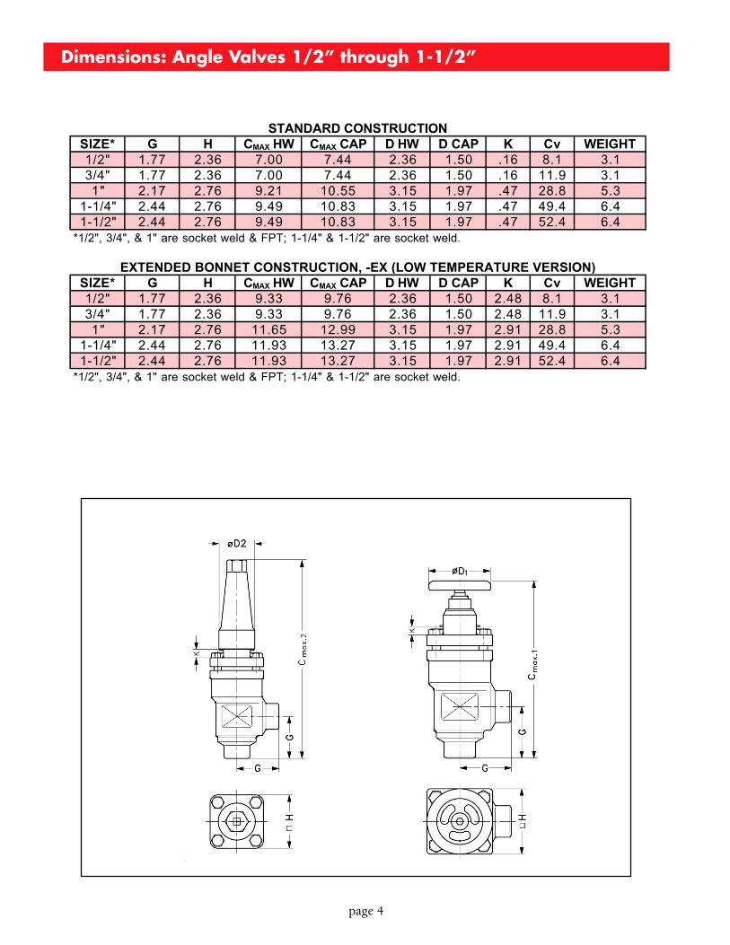
Dimensions: Angle Valves 1/2” through 1-1/2”
SIZE* G H CMAX HW CMAX CAP D HW D CAP K Cv WEIGHT1/2" 1.77 2.36 7.00 7.44 2.36 1.50 .16 8.1 3.13/4" 1.77 2.36 7.00 7.44 2.36 1.50 .16 11.9 3.11" 2.17 2.76 9.21 10.55 3.15 1.97 .47 28.8 5.3
1-1/4" 2.44 2.76 9.49 10.83 3.15 1.97 .47 49.4 6.41-1/2" 2.44 2.76 9.49 10.83 3.15 1.97 .47 52.4 6.4
SIZE* G H CMAX HW CMAX CAP D HW D CAP K Cv WEIGHT1/2" 1.77 2.36 9.33 9.76 2.36 1.50 2.48 8.1 3.13/4" 1.77 2.36 9.33 9.76 2.36 1.50 2.48 11.9 3.11" 2.17 2.76 11.65 12.99 3.15 1.97 2.91 28.8 5.3
1-1/4" 2.44 2.76 11.93 13.27 3.15 1.97 2.91 49.4 6.41-1/2" 2.44 2.76 11.93 13.27 3.15 1.97 2.91 52.4 6.4
*1/2", 3/4", & 1" are socket weld & FPT; 1-1/4" & 1-1/2" are socket weld.
STANDARD CONSTRUCTION
*1/2", 3/4", & 1" are socket weld & FPT; 1-1/4" & 1-1/2" are socket weld.
EXTENDED BONNET CONSTRUCTION, -EX (LOW TEMPERATURE VERSION)
page 5
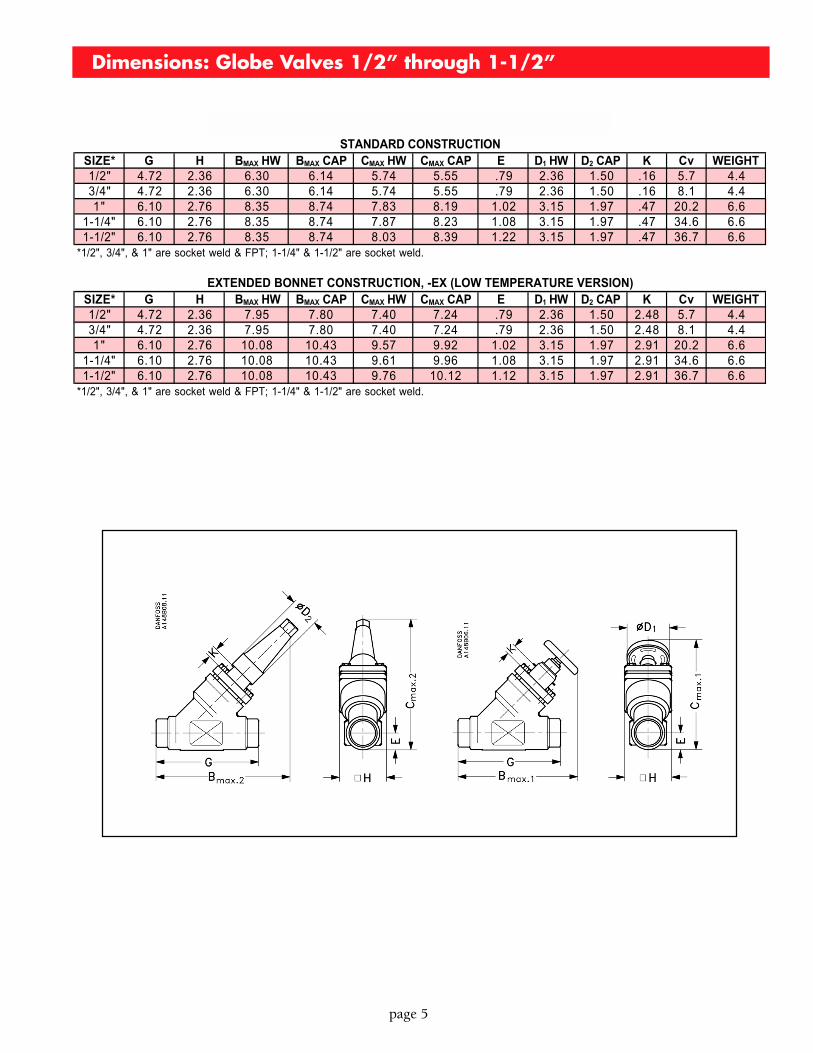
Dimensions: Globe Valves 1/2” through 1-1/2”
SIZE* G H BMAX HW BMAX CAP CMAX HW CMAX CAP E D1 HW D2 CAP K Cv WEIGHT1/2" 4.72 2.36 6.30 6.14 5.74 5.55 .79 2.36 1.50 .16 5.7 4.43/4" 4.72 2.36 6.30 6.14 5.74 5.55 .79 2.36 1.50 .16 8.1 4.41" 6.10 2.76 8.35 8.74 7.83 8.19 1.02 3.15 1.97 .47 20.2 6.6
1-1/4" 6.10 2.76 8.35 8.74 7.87 8.23 1.08 3.15 1.97 .47 34.6 6.61-1/2" 6.10 2.76 8.35 8.74 8.03 8.39 1.22 3.15 1.97 .47 36.7 6.6
SIZE* G H BMAX HW BMAX CAP CMAX HW CMAX CAP E D1 HW D2 CAP K Cv WEIGHT1/2" 4.72 2.36 7.95 7.80 7.40 7.24 .79 2.36 1.50 2.48 5.7 4.43/4" 4.72 2.36 7.95 7.80 7.40 7.24 .79 2.36 1.50 2.48 8.1 4.41" 6.10 2.76 10.08 10.43 9.57 9.92 1.02 3.15 1.97 2.91 20.2 6.6
1-1/4" 6.10 2.76 10.08 10.43 9.61 9.96 1.08 3.15 1.97 2.91 34.6 6.61-1/2" 6.10 2.76 10.08 10.43 9.76 10.12 1.12 3.15 1.97 2.91 36.7 6.6
*1/2", 3/4", & 1" are socket weld & FPT; 1-1/4" & 1-1/2" are socket weld.
*1/2", 3/4", & 1" are socket weld & FPT; 1-1/4" & 1-1/2" are socket weld.
STANDARD CONSTRUCTION
EXTENDED BONNET CONSTRUCTION, -EX (LOW TEMPERATURE VERSION)
page 6
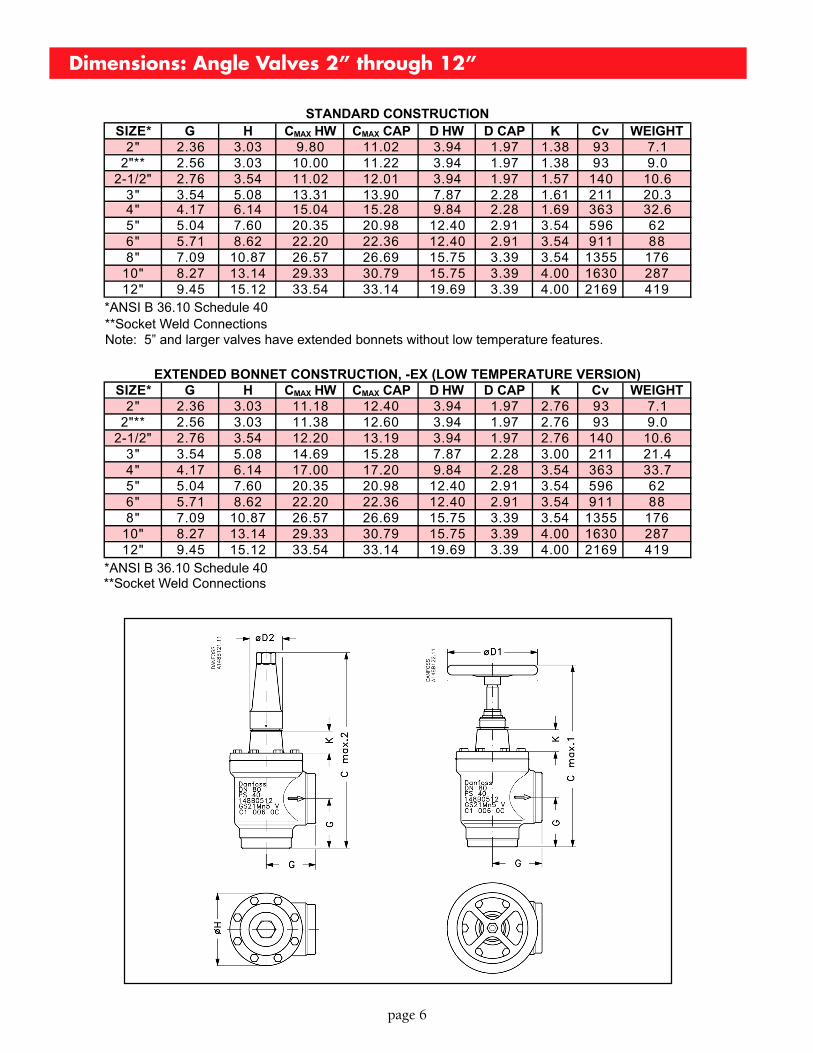
Dimensions: Angle Valves 2” through 12”
Note: 5” and larger valves have extended bonnets without low temperature features.
*ANSI B 36.10 Schedule 40
**Socket Weld Connections*ANSI B 36.10 Schedule 40
**Socket Weld Connections
SIZE* G H CMAX HW CMAX CAP D HW D CAP K Cv WEIGHT2" 2.36 3.03 9.80 11.02 3.94 1.97 1.38 93 7.1
2"** 2.56 3.03 10.00 11.22 3.94 1.97 1.38 93 9.02-1/2" 2.76 3.54 11.02 12.01 3.94 1.97 1.57 140 10.6
3" 3.54 5.08 13.31 13.90 7.87 2.28 1.61 211 20.34" 4.17 6.14 15.04 15.28 9.84 2.28 1.69 363 32.65" 5.04 7.60 20.35 20.98 12.40 2.91 3.54 596 626" 5.71 8.62 22.20 22.36 12.40 2.91 3.54 911 888" 7.09 10.87 26.57 26.69 15.75 3.39 3.54 1355 176
10" 8.27 13.14 29.33 30.79 15.75 3.39 4.00 1630 28712" 9.45 15.12 33.54 33.14 19.69 3.39 4.00 2169 419
STANDARD CONSTRUCTION
SIZE* G H CMAX HW CMAX CAP D HW D CAP K Cv WEIGHT2" 2.36 3.03 11.18 12.40 3.94 1.97 2.76 93 7.1
2"** 2.56 3.03 11.38 12.60 3.94 1.97 2.76 93 9.02-1/2" 2.76 3.54 12.20 13.19 3.94 1.97 2.76 140 10.6
3" 3.54 5.08 14.69 15.28 7.87 2.28 3.00 211 21.44" 4.17 6.14 17.00 17.20 9.84 2.28 3.54 363 33.75" 5.04 7.60 20.35 20.98 12.40 2.91 3.54 596 626" 5.71 8.62 22.20 22.36 12.40 2.91 3.54 911 888" 7.09 10.87 26.57 26.69 15.75 3.39 3.54 1355 176
10" 8.27 13.14 29.33 30.79 15.75 3.39 4.00 1630 28712" 9.45 15.12 33.54 33.14 19.69 3.39 4.00 2169 419
EXTENDED BONNET CONSTRUCTION, -EX (LOW TEMPERATURE VERSION)
page 7
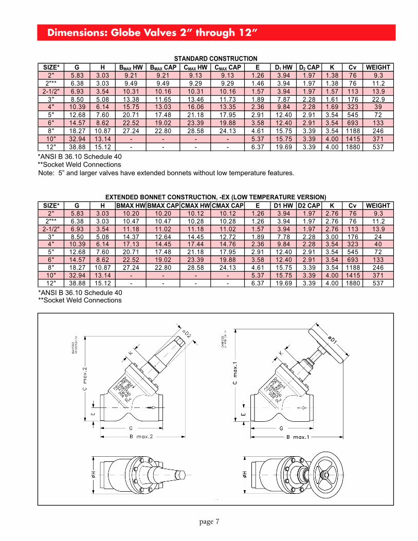
Dimensions: Globe Valves 2” through 12”
Note: 5” and larger valves have extended bonnets without low temperature features.
*ANSI B 36.10 Schedule 40**Socket Weld Connections
*ANSI B 36.10 Schedule 40**Socket Weld Connections
SIZE* G H BMAX HW BMAX CAP CMAX HW CMAX CAP E D1 HW D2 CAP K Cv WEIGHT2" 5.83 3.03 9.21 9.21 9.13 9.13 1.26 3.94 1.97 1.38 76 9.3
2"** 6.38 3.03 9.49 9.49 9.29 9.29 1.46 3.94 1.97 1.38 76 11.22-1/2" 6.93 3.54 10.31 10.16 10.31 10.16 1.57 3.94 1.97 1.57 113 13.9
3" 8.50 5.08 13.38 11.65 13.46 11.73 1.89 7.87 2.28 1.61 176 22.94" 10.39 6.14 15.75 13.03 16.06 13.35 2.36 9.84 2.28 1.69 323 395" 12.68 7.60 20.71 17.48 21.18 17.95 2.91 12.40 2.91 3.54 545 726" 14.57 8.62 22.52 19.02 23.39 19.88 3.58 12.40 2.91 3.54 693 1338" 18.27 10.87 27.24 22.80 28.58 24.13 4.61 15.75 3.39 3.54 1188 246
10" 32.94 13.14 - - - - 5.37 15.75 3.39 4.00 1415 37112" 38.88 15.12 - - - - 6.37 19.69 3.39 4.00 1880 537
STANDARD CONSTRUCTION
SIZE* G H BMAX HW BMAX CAP CMAX HW CMAX CAP E D1 HW D2 CAP K Cv WEIGHT2" 5.83 3.03 10.20 10.20 10.12 10.12 1.26 3.94 1.97 2.76 76 9.3
2"** 6.38 3.03 10.47 10.47 10.28 10.28 1.26 3.94 1.97 2.76 76 11.22-1/2" 6.93 3.54 11.18 11.02 11.18 11.02 1.57 3.94 1.97 2.76 113 13.9
3" 8.50 5.08 14.37 12.64 14.45 12.72 1.89 7.78 2.28 3.00 176 244" 10.39 6.14 17.13 14.45 17.44 14.76 2.36 9.84 2.28 3.54 323 405" 12.68 7.60 20.71 17.48 21.18 17.95 2.91 12.40 2.91 3.54 545 726" 14.57 8.62 22.52 19.02 23.39 19.88 3.58 12.40 2.91 3.54 693 1338" 18.27 10.87 27.24 22.80 28.58 24.13 4.61 15.75 3.39 3.54 1188 246
10" 32.94 13.14 - - - - 5.37 15.75 3.39 4.00 1415 37112" 38.88 15.12 - - - - 6.37 19.69 3.39 4.00 1880 537
EXTENDED BONNET CONSTRUCTION, -EX (LOW TEMPERATURE VERSION)
page 8
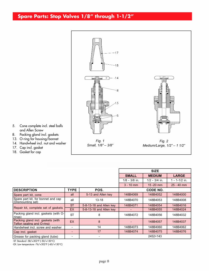
Spare Parts: Stop Valves 1/8” through 1-1/2”
5. Cone complete incl. steel ballsand Allen Screw
8. Packing gland incl. gaskets13. O-ring for housing/bonnet14. Handwheel incl. nut and washer17. Cap incl. gasket18. Gasket for cap
Fig. 1Small, 1/8” – 3/8”
Fig. 2Medium/Large, 1/2” – 1 1/2”
SMALL MEDIUM LARGE1/8 - 3/8 in. 1/2 - 3/4 in. 1 - 1-1/2 in.
3 - 10 mm 15 -20 mm 25 - 40 mm
DESCRIPTION TYPE POS.
Spare part kit, cone all 5-13 and Allen key 148B4069 148B4052 148B4000
Spare part kit, for bonnet and cap (Dismounting set)
all 13-18 148B4070 148B4053 148B4008
ST 5-8-13-18 and Allen key 148B4071 148B4054 148B4016EX 5-8-13-18 and Allen key - 148B4055 148B4024
Packing gland incl. gaskets (with O-rings)
ST 8 148B4072 148B4056 148B4032
Packing gland incl. gaskets (with Teflon sealing and O-ring)
EX 8 - 148B4057 148B4037
Handwheel incl. screw and washer - 14 148B4073 148B4060 148B4062
Cap incl. gasket - 17 148B4074 148B4075 148B4076
Grease for packing gland (tube) - -
SPARE PARTS: STOP VALVES 1/8" THROUGH 1-1/2"
CODE NO.
SIZE
2452+143
Repair kit, complete set of gaskets
-ST: Standard -58/+302°F (-50/+150°C)-EX: Low temperature -76/+302°F (-60/+150°C)
page 9
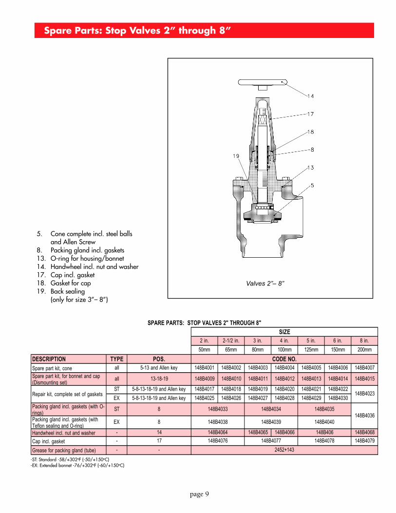
-ST: Standard -58/+302oF (-50/+150oC)-EX: Extended bonnet -76/+302oF (-60/+150oC)
5. Cone complete incl. steel ballsand Allen Screw
8. Packing gland incl. gaskets13. O-ring for housing/bonnet14. Handwheel incl. nut and washer17. Cap incl. gasket18. Gasket for cap19. Back sealing
(only for size 3”– 8”)
Valves 2”– 8”
Spare Parts: Stop Valves 2” through 8”
2 in. 2-1/2 in. 3 in. 4 in. 5 in. 6 in. 8 in.
50mm 65mm 80mm 100mm 125mm 150mm 200mm
DESCRIPTION TYPE POS.
Spare part kit, cone all 5-13 and Allen key 148B4001 148B4002 148B4003 148B4004 148B4005 148B4006 148B4007
Spare part kit, for bonnet and cap (Dismounting set)
all 13-18-19 148B4009 148B4010 148B4011 148B4012 148B4013 148B4014 148B4015
ST 5-8-13-18-19 and Allen key 148B4017 148B4018 148B4019 148B4020 148B4021 148B4022
EX 5-8-13-18-19 and Allen key 148B4025 148B4026 148B4027 148B4028 148B4029 148B4030
Packing gland incl. gaskets (with O-rings)
ST 8
Packing gland incl. gaskets (with Teflon sealing and O-ring)
EX 8
Handwheel incl. nut and washer - 14 148B4065 148B4066 148B4068
Cap incl. gasket - 17 148B4079
Grease for packing gland (tube) - -
Repair kit, complete set of gaskets
148B4033 148B4034 148B4035
148B406
148B4078
148B4036
SIZE
CODE NO.
148B4023
SPARE PARTS: STOP VALVES 2" THROUGH 8"
148B4038
148B4064
148B4076
2452+143
148B4039
148B4077
148B4040
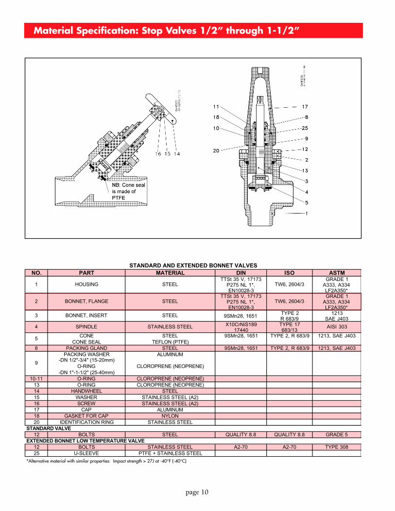
Material Specification: Stop Valves 1/2” through 1-1/2”
page 10
NO. PART MATERIAL DIN ISO ASTM
1 HOUSING STEELTTSt 35 V, 17173
P275 NL 1*, EN10028-3
TW6, 2604/3GRADE 1
A333, A334 LF2A350*
2 BONNET, FLANGE STEELTTSt 35 V, 17173
P275 NL 1*, EN10028-3
TW6, 2604/3GRADE 1
A333, A334 LF2A350*
3 BONNET, INSERT STEEL 9SMn28, 1651 TYPE 2 R 683/9
1213 SAE J403
4 SPINDLE STAINLESS STEEL X10CrNiS189 17440
TYPE 17 683/13
AISI 303
CONE STEEL 9SMn28, 1651 TYPE 2, R 683/9 1213, SAE J403CONE SEAL TEFLON (PTFE)
8 PACKING GLAND STEEL 9SMn28, 1651 TYPE 2, R 683/9 1213, SAE J403PACKING WASHER ALUMINUM
-DN 1/2"-3/4" (15-20mm)O-RING CLOROPRENE (NEOPRENE)
-DN 1"-1-1/2" (25-40mm)10-11 O-RING CLOROPRENE (NEOPRENE)
13 O-RING CLOROPRENE (NEOPRENE)14 HANDWHEEL STEEL15 WASHER STAINLESS STEEL (A2)16 SCREW STAINLESS STEEL (A2)17 CAP ALUMINUM18 GASKET FOR CAP NYLON20 IDENTIFICATION RING STAINLESS STEEL
12 BOLTS STEEL QUALITY 8.8 QUALITY 8.8 GRADE 5
12 BOLTS STAINLESS STEEL A2-70 A2-70 TYPE 30825 U-SLEEVE PTFE + STAINLESS STEEL
STANDARD AND EXTENDED BONNET VALVES
5
9
STANDARD VALVE
EXTENDED BONNET LOW TEMPERATURE VALVE
*Alternative material with similar properties: Impact strength > 27J at -40°F (-40°C)
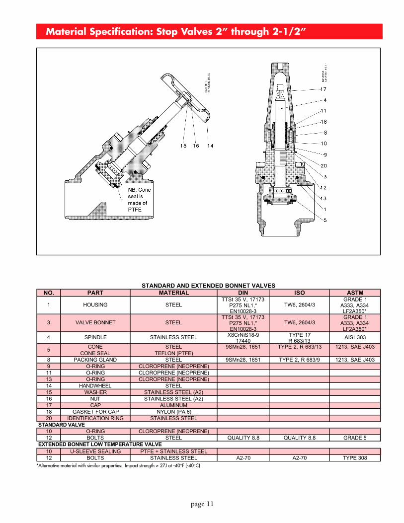
Material Specification: Stop Valves 2” through 2-1/2”
page 11
NO. PART MATERIAL DIN ISO ASTM
1 HOUSING STEELTTSt 35 V, 17173
P275 NL1,* EN10028-3
TW6, 2604/3GRADE 1
A333, A334 LF2A350*
3 VALVE BONNET STEELTTSt 35 V, 17173
P275 NL1,* EN10028-3
TW6, 2604/3GRADE 1
A333, A334 LF2A350*
4 SPINDLE STAINLESS STEEL X8CrNiS18-9 17440
TYPE 17 R 683/13
AISI 303
CONE STEEL 9SMn28, 1651 TYPE 2, R 683/13 1213, SAE J403CONE SEAL TEFLON (PTFE)
8 PACKING GLAND STEEL 9SMn28, 1651 TYPE 2, R 683/9 1213, SAE J4039 O-RING CLOROPRENE (NEOPRENE)11 O-RING CLOROPRENE (NEOPRENE)13 O-RING CLOROPRENE (NEOPRENE)14 HANDWHEEL STEEL15 WASHER STAINLESS STEEL (A2)16 NUT STAINLESS STEEL (A2)17 CAP ALUMINUM18 GASKET FOR CAP NYLON (PA 6)20 IDENTIFICATION RING STAINLESS STEEL
10 O-RING CLOROPRENE (NEOPRENE)12 BOLTS STEEL QUALITY 8.8 QUALITY 8.8 GRADE 5
10 U-SLEEVE SEALING PTFE + STAINLESS STEEL12 BOLTS STAINLESS STEEL A2-70 A2-70 TYPE 308
5
STANDARD AND EXTENDED BONNET VALVES
STANDARD VALVE
EXTENDED BONNET LOW TEMPERATURE VALVE
*Alternative material with similar properties: Impact strength > 27J at -40°F (-40°C)
H. A. Phillips & Co.1775 Wallace AvenueSt.Charles, Illinois 60174-3402 U.S.A.Phone: (630) 377-0050 • Fax: (630) 377-2706E-mail: [email protected] visit us @ www.haphillips.com
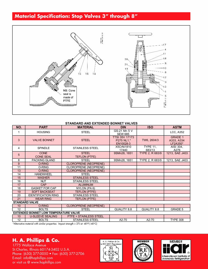
Material Specification: Stop Valves 3” through 8”
NO. PART MATERIAL DIN ISO ASTM
1 HOUSING STEEL GS-21 Mn 5 V SEW 685
LCC, A352
3 VALVE BONNET STEELTTSt 35V 17173
P275 NL1,* EN10028-3
TW6, 2604/3GRADE 1
A333, A334 LF2A350*
4 SPINDLE STAINLESS STEEL X5CrNi1810 17440
TYPE 11, 683/13
AISI 304, A276
CONE STEEL 9SMn28, 1651 TYPE 2, R 683/9 1213, SAE J403CONE SEAL TEFLON (PTFE)
8 PACKING GLAND STEEL 9SMn28, 1651 TYPE 2, R 683/9 1213, SAE J4039 O-RING CLOROPRENE (NEOPRENE)11 O-RING CLOROPRENE (NEOPRENE)13 O-RING CLOROPRENE (NEOPRENE)14 HANDWHEEL STEEL15 WASHER STAINLESS STEEL16 NUT STAINLESS STEEL17 CAP ALUMINUM18 GASKET FOR CAP NYLON (PA 6)19 SOFT BACKSEAT TEFLON (PTFE)20 IDENTIFICATION RING STAINLESS STEEL21 WEAR RING TEFLON (PTFE)
10 O-RING CLOROPRENE (NEOPRENE)12 BOLTS STEEL QUALITY 8.8 QUALITY 8.8 GRADE 5
10 U-SLEEVE SEALING PTFE + STAINLESS STEEL12 BOLTS STAINLESS STEEL A2-70 A2-70 TYPE 308
STANDARD AND EXTENDED BONNET VALVES
EXTENDED BONNET LOW TEMPERATURE VALVE
STANDARD VALVE
5
*Alternative material with similar properties: Impact strength > 27J at -40°F (-40°C)