Embed Size (px)
Citation preview

SOLAR
PRODUCTSCATALOG
PGR-8800 ARC-FLASH RELAY
TECHNICAL FAQ

©April 2012 Littelfuse, Inc.www.littelfuse.com/protectionrelays
PGR-8800 Arc-Flash Relay Technical FAQ
2
The PGR-8800 can be used on electrical systems operating at any voltage (AC or DC) since it does not directly connect to the system. The system is monitored with light sensors and optional current transformers (for AC systems) that can be selected for any current / voltage rating. The small size of the PGR-8800 allows for installation in any switchgear cubicle, transformer compartment, or motor control center bucket.
A phase-to-phase fault within a 480 volt system with 20,000 ampere of fault current provides 9,600,000 watts of power. Imagine that there is no arc protection and the fault is allowed to last for 200 milliseconds. The resulting energy would be 1,920,000 Joules. TNT releases approximately 2,175 Joules/gram when detonated, so this arc flash would approximately correspond to the detonation of 883 grams of TNT. One stick of dynamite contains approximately 1,000 grams of TNT.
The formula is as follows:
Energy = (voltage x current) x duration = (480 V x 20,000 A) x 200 ms =1,920,000 J
The formula clearly shows that the destruction depends on power over time, which is in fact the formula for energy. The main task of the PGR-8800 is to quickly detect the release of power and limit its lifespan.
It goes without saying that nobody would like to have a half a stick of dynamite sitting inside their installation, just waiting to explode. The PGR-8800 arc fault protection device, could have extinguished the arc fault in less than 35 milliseconds.
What are the typical applications / system voltages?
How much energy is in a typical arc-flash incident?
There are two ways to lower the incident energy of an arc-flash event, reducing the fault current or the clearing time. Reducing the available energy could in turn lower the required PPE. Reducing the current can be achieved by using current-limiting fuses and, for single-phase faults, resistance grounding.
Reducing the clearing time typically is not possible when using overcurrent protection due to system coordination requirements. Current-based protection must have sufficient delay to prevent unnecessary tripping on momentary overload or current spikes, thus losing valuable reaction time.
Reducing the clearing time typically is not possible when using standard overcurrent protection due to system coordination requirements. Current-based protection must have sufficient delay to prevent unnecessary tripping on momentary overload or current spikes, thus losing valuable reaction time.
Arc Flash relays resolve this issue by detecting overcurrent and light ,which allows for the quickest reaction time in the industry. The PGR-8800 relay can detect an arcing condition and send a trip signal to the circuit breaker within 1ms. This detection time is much faster than standard protection and circuit breakers, which means using an Arc Flash relay in combination with a circuit breaker will lower the incident energy or Arc Flash hazards. This results in an increase in worker safety, less fault damage, and improved uptime. Since the arc-flash hazard has decreased, the associated PPE may also be lowered. The exact amount will depend on user setpoints, so it must be modeled in the system to determine the new incident energy and PPE.
Do Arc Flash relays lower Personal Protective
Equipment (PPE)?
©April 2012 Littelfuse, Inc. www.littelfuse.com/protectionrelays
PGR-8800 Arc-Flash Relay Technical FAQ
3
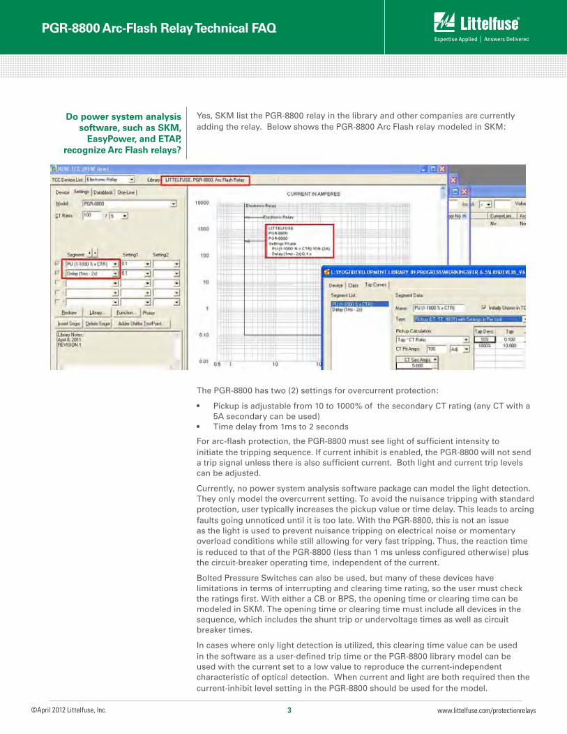
Yes, SKM list the PGR-8800 relay in the library and other companies are currently adding the relay. Below shows the PGR-8800 Arc Flash relay modeled in SKM:
The PGR-8800 has two (2) settings for overcurrent protection:
• Pickupisadjustablefrom10to1000%ofthesecondaryCTrating(anyCTwitha5A secondary can be used)
• Timedelayfrom1msto2seconds
For arc-flash protection, the PGR-8800 must see light of sufficient intensity to initiate the tripping sequence. If current inhibit is enabled, the PGR-8800 will not send a trip signal unless there is also sufficient current. Both light and current trip levels can be adjusted.
Currently, no power system analysis software package can model the light detection. They only model the overcurrent setting. To avoid the nuisance tripping with standard protection, user typically increases the pickup value or time delay. This leads to arcing faults going unnoticed until it is too late. With the PGR-8800, this is not an issue as the light is used to prevent nuisance tripping on electrical noise or momentary overload conditions while still allowing for very fast tripping. Thus, the reaction time is reduced to that of the PGR-8800 (less than 1 ms unless configured otherwise) plus the circuit-breaker operating time, independent of the current.
Bolted Pressure Switches can also be used, but many of these devices have limitations in terms of interrupting and clearing time rating, so the user must check the ratings first. With either a CB or BPS, the opening time or clearing time can be modeled in SKM. The opening time or clearing time must include all devices in the sequence, which includes the shunt trip or undervoltage times as well as circuit breaker times.
In cases where only light detection is utilized, this clearing time value can be used in the software as a user-defined trip time or the PGR-8800 library model can be used with the current set to a low value to reproduce the current-independent characteristic of optical detection. When current and light are both required then the current-inhibit level setting in the PGR-8800 should be used for the model.
Do power system analysis software, such as SKM,
EasyPower, and ETAP, recognize Arc Flash relays?

©April 2012 Littelfuse, Inc.www.littelfuse.com/protectionrelays
PGR-8800 Arc-Flash Relay Technical FAQ
4
How do Arc Flash relays coordinate with other
protection relays?
These are different technologies that detect and quickly clear faults. ZSIP will detect a fault and block an upstream protective device from operating until the local protective device has a chance to clear the fault. If not, the upstream device attempts to clear it. This takes valuable time (100ms for detection only) and may be difficult to retrofit.
Bus Differential measures the difference of current going into and out of a device, such as switchgear. If the current supplied by the source travels through the switchgear to the load, all is well. If a fault occurs within the switchgear, the current going in does not equal the current going to the load. This detection method is much quicker (33ms for detection only) and may be more difficult and/or expensive to retrofit, depending on the number of CTs.
Yes, the arc flash relay has 6 sensors that can be installed in each cubicle, compartment, or bucket. Each sensor has an on-board LED as well as an LED on the PGR-8800 that provides feedback identifying which zone caused the fault. The arc flash relay has one set of contacts to trip the main circuit breaker. Protection zones can be implemented by connecting up to 4 PGR-8800’s (up to 24 sensors) to a breaker.
If individual circuit protection is desired, the built-in light sensor on the front of the relay can be utilized. Simply install the PGR-8800 arc flash relay in each cubicle and connect to the associated feeder circuit breaker.
How Arc Flash relays compare to Zone Selective
Interlocking Protection (ZSIP)and Bus Differential?
Do Arc Flash relays provide zone identification?
Power system analysis software programs can be used to help with system coordination.Thearcflashrelayhastwodefinite-timesettings(10-1000%full-load current and 1ms – 20s time delay) that can be used for coordination, however, both control one set of output trip contact. One setpoint can be used for detecting a low-level arcing condition and the other can be used for detecting high-level arcing condition. If either condition is met, a trip signal is sent to the circuit breaker.
Coordination for arc-flash protection is not practical due to the reaction time required and utilizing light as a fault detection method.

©April 2012 Littelfuse, Inc. www.littelfuse.com/protectionrelays
PGR-8800 Arc-Flash Relay Technical FAQ
5
The PGR-8800 Arc-Flash Relay and sensors are easily installed in retrofit projects and new switchgear with little or no re-configuration. Even elaborate systems with multiple power sources take minutes to configure using the relay’s built-in USB interface software.
Generally, it is recommended to mount 1 or 2 sensors per cubicle to cover all horizontal and vertical bus bars, breaker compartments, drawers, and anywhere that there is potential for an arc-fault. Threading a fiber-optic sensor through the cabinets and in areas where point-sensor coverage is uncertain results in complete coverage and an added level of redundancy. Even if policy is to only work on de-energized systems, all maintenance area should be monitored to prevent potential damage and additional cost. At least once sensor should have visibility of an arc fault if a person blocks the other sensor(s).
Below are some additional guidelines:
• Firstdeterminesensorplacements,thenconsiderzones.• Ensuresensorsandcablesarenotblockedbyobjects,eitherfixedormovable.• Donotplacesensorsorfibercableonliveorenergizedcomponents.• Chosealocationthatwillminimizecollectionofforeigndebrisandeasy
access for maintenance, if needed.• Usecarewhenhandling,pulling,andsecuringcables.• Avoidsharpbends(<2cm)andhightemperature(>80C).• Considerplacementsaroundair-magneticcircuitbreakers.• Considermovablepartsandareaaccessibletopersonnelforcommissioning,
testing, inspecting, etc.• Eventhoughthesensorsandcableshavenoexposedlivepartsarefully
insulated, the placement and routing must comply with industry standard requirements on over-surface (creep) and through-air (clearance).
What are the installation guidelines for the sensors?
PGA-LS10 Point Sensor Line-of-sight light sensor with a built-in LED to indicate sensor health or trip state. Comes standard with a 32-foot cable.
PGA-LS20 Fiber-Optic Sensor A 360°, 26-foot fiber-optic sensor detects light along the entire length of the cable and has a built-in LED to indicate sensor health or trip state. Recommended installation is along busbars as well as in challenging spaces that have many compartments. Comes standard with two 32-foot cables
Phase Current Transformers Phase Current Transformers (CTs) are required to detect phase currents. When retrofitting systems, existing CTs with a 5 A secondary can be used.
A
B
C
C C C

©April 2012 Littelfuse, Inc.www.littelfuse.com/protectionrelays
PGR-8800 Arc-Flash Relay Technical FAQ
6
Each sensor has an internal health LED. Its purpose is to verify the continuity of the sensor cabling and the internal sensor circuitry. This ‘health check’ circuit will not detect dust buildup on the sensor. There are several ways to mitigate dust buildup. A sensor mounted at the top of an enclosure looking down is optimal. This configuration will not collect much dust in most cabinet installations, due to intensity of an arc combined with the reflections off the metal walls (even a dirty sensor will collect a great deal of light).
Sensors must be cleaned in order to maintain consistent sensitivity. Sensor cleaning should be part of regular maintenance and should be performed via compressed air or dry wipe down. A maintenance routine can be implemented to clean sensors at a set interval that is aligned with industry standard recommendations, such as NFPA 70B, Recommended Practice for Equipment Maintenance.
A more proactive approach could also be used by putting the relay into Service Mode and shining a bright light on each sensor. A trip will be indicated if the sensor is able to detect the light but the breaker will not be tripped. If the relay light isn’t indicating a trip then cleaning is necessary.
The purpose of the Current Transformers (CTs) is to validate an arcing condition, although CTs are not required for operation. The PGR-8800 relay will detect light and send a trip signal. If the CTs are used, the Arc Flash relay will only send a trip signal if both light and overcurrent conditions are detected. If only light detection (optical sensors) is used, an event, such as a camera flash or direct sunlight, may cause the Arc Flash relay to operate. In applications where intense light is a possibility, overcurrent detection can be used to prevent nuisance tripping.
The PGR-8800 relay accepts any CT with a 5A secondary. Existing CTs may be used for retrofit opportunities. The CTs are sized per typical conventional protection methods. For example, the CT primary rating is typically determined by the rating of the equipment. If a switchgear is rated for 2,000 A, a 2000:5 CT is usually selected.
Yes, in many cases. It depends on the available fault current and how much faster the PGR-8800 causes the upstream breaker to clear the fault.
If the worker is within the Flash Protection Boundary of the exposed (line of sight) energized part, then the PPE category on the label must be used. If the door is closed or cover is on, check NFPA 70E Table 130.7(C)(15)(a) or (b) for a possible reduction in HRC.
Is there a maintenance schedule for the sensors?
What is the purpose of the CTs and are they required?
Can arc-flash relays eliminate the need for
HRC 3 or 4 clothing?
It seems that “working” on the equipment is the key.
How about just walking or standing in front of the
equipment. Or opening equipment cabinet to
read a nameplate e.g. pad mount transformers?

©April 2012 Littelfuse, Inc. www.littelfuse.com/protectionrelays
PGR-8800 Arc-Flash Relay Technical FAQ
7
Hospitals and health care facilities are not exempted from OSHA safety requirements. They rely on the experience and reputation of the Professional Engineer’s assessment.
In general, unless the doors are open or covers are off and the worker is exposed to energized circuit parts, if the equipment is arc resistant, then arc flash protection boundaries are minimized. Check with the manufacturer for minimum suggested working distances.
According to IEEE 1584, If the voltage is 240 volts or less, and fed by a single transformer rated 125 kVA or less, the HRC is usually considered HRC 0.
AccordingtoIEEE1584,thearcingcurrentcanbeaslowas38%oftheavailablebolted fault current. If the instantaneous trip setting of the circuit breaker is greater than the arcing current, the breaker could take seconds or minutes to open, thus creating a potentially DANGEROUS arc flash condition. The Arc Flash relay can react in 1 millisecond regardless of the fault current, and initiate the tripping signal to open the breaker and clear the fault within 30 msec or less, lowering the arc flash incident energy to a minimum.
If the incident energy is the same, NO. However, if the incident energy is more or less, NFPA 70E requires the worker to use arc rated clothing equal to or greater than the possible maximum incident energy.
NFPA 70E Article 130.5 requires the arc flash analysis to be updated when major modifications occur and reviewed every 5 years, whichever occurs first.
We recommend you contact the engineer or engineering firm that performed the assessment and request them to re-run the study at that equipment using the PGR-8800 relay to lower the hazards.
What are the regulatory agencies’ opinion on arc-flash relays on life safety
and critical circuits?
Do we have to maintain clearance between panels if lined up opposite, even
if the switchgear is arc resistant type?
Can greater than 75 kVA transformers mitigate
the arc flash labels and requirements?
When working on an energized transformer, we
use instantaneous settings at the feeder breaker relay.
Can the arc-flash relay bring any benefit?
When designing a safety protocol, should low fault current-long clearing time
hazard and a high-fault current-short clearing time hazard with
the same incident energy be treated differently?
Is their a recommendation as to how often you need to
update the arc flash label?
We recently completed an arc-flash hazard assessment and
have a few dangerous level categories. How can I tell if
the arc-flash relay is going to reduce those levels and will
that change the amount of PPE required?

©April 2012 Littelfuse, Inc.www.littelfuse.com/protectionrelays
PGR-8800 Arc-Flash Relay Technical FAQ
8
Are there control systems available that truly eliminate or
control arc flash?
Does implementation of an arc-flash relay allow a worker to use a reduced level of PPE?
How do you test the sensors, are they fail safe?
How do the CT’s input help the performance of the relay
If the equipment is energized there is no one system that does that.
In most cases, YES, but please check with the engineer or engineering firm that performed the assessment and request them to re-run the study at the higher PPE levels to determine if the arc flash relay will lower the incident energy and PPE required.
A sensor-check circuit in the PGR-8800 tests the sensor once per second to verify that the sensor assembly is functioning correctly and that is connected. The signal is sent from the PGR-8800 along the cable to the sensor which activates an internal LED. A failure in the sensor circuitry or cable would result in a loss of check signal. The PGR-8800 recognizes this signal loss as a loss of sensor and will indicate an error condition on the sensor and on the relay, and the ONLINE output will change state. The user can decide what to do with this relay output and whether it will trip the system or simply signal an alarm. The fiber-optic sensor works the same way except that the signal travels through the length of the fiber-optic cable so a break or crimp in that cable is detected.
Sensors can be tested individually by putting the PGR-8800 into Service mode and shining a bright light source on the sensor. A trip will be indicated if the sensor is able to detect the light but a trip signal will not be sent to the breaker. A high-power flashlight can serve to verify the sensors are properly detecting light. The power required on the flashlight is difficult to quantify because of the way the light is spread and focused, but a 3 million candle power flashlight has proven more than sufficient for use on point sensors.
The CT inputs provide optional current measurement, protection, and restraint. In applications with indoor lighting and no high-intensity light sources (welding, direct sunlight) nearby, current measurement may not be of benefit to the relay aside from high-level overcurrent protection. However, for applications where high intensity light could be incident on an arc-flash sensor, the current measurement ability acts as a second-level verification in addition to light. If there is intense light on the sensor but the current is normal, the PGR-8800 can be configured to ignore the light. If there is higher than normal current AND there is also intense light as from an arc flash, then the relay will trip. The current effectively supervises the operation of the light-tripping mechanism and allows nuisance-free operation of the relay in applications with optical noise.
The PGR-8800 can be configured to trip between 10 klux and 40 klux. The relay’s six sensor LEDs can be configured to indicate at various levels below the trip level to warn that light intensity is approaching the trip level.
The fiber-optic sensor has an adjustable sensitivity (in addition to the relay sensitivity dial) that could be used to increase the sensitivity for a given length of fiber to levels below and above the relay setpoint.
At what intensity of light will the PGR-8800
indicate or trip

©April 2012 Littelfuse, Inc. www.littelfuse.com/protectionrelays
PGR-8800 Arc-Flash Relay Technical FAQ
9
This is a difficult metric to provide because the distance an arc can be detected by the fiber-optic sensor is dependent on many variables. However, the PGA-LS20 fiber-optic sensor is factory calibrated so that it will have the same detection range as the PGA-LS10 when 60 cm (a standard section width) is exposed to the arc flash. In other words, a 3 kA arc can be detected from a distance of 2 m from the fiber assuming that the light is incident on 60 cm of fiber. However, the PGA-LS20 also has an adjustment screw that allows the user to calibrate the fiber-optic sensor to be more sensitive (for smaller sections) or less sensitive (for larger ones) so that the characteristic matches that PGA-LS10 point sensors. We recommend a minimum of 20 cm of fiber exposed per section.
The fiber-optic sensors have two parts, an electrical cable connection to the relay and the light-sensitive fiber-optic cable. Splitting a fiber is a challenge because a bad splice can result in decreased or increased sensitivity and failure to operate or nuisance tripping. Shipping splits should be wired so that the fiber-optic sensor cable does not traverse multiple sections. The electrical part of the sensor, connecting the sensor to the relay, can be up to 50 m long and is much easier to connect at the final installation as well as much more durable than optical fiber. It is important to remember that a light-collecting fiber-optic cable behaves quite differently from a transmission-only shielded fiber-optic cable. The latter case is more frequently used, especially in telecommunications industries and can have very large lengths, but in that case light is fed directly into the tube at a low angle of incidence and losses along the cable are very low. In the PGA-LS20 fiber-optic sensor, the entire cable is designed to absorb light incident on the surface, bend the light to trap it in the cable, and then keep it in the cable. However, light is lost along the length of the cable and the longer the light must travel along the cable, the more light is lost. Our testing shows that beyond 8 m, the amount of light lost along the length of the fiber-optic cable is sufficient to result in less sensitivity at the ‘transmitter’ side of the fiber compared to the receiver. For this reason, multiple lengths are not specified. Repeaters are not available as the cost may be too high compared to installing a second fiber-optic sensor. Repeaters may cause timing issues for the sensor-check signal.
What is detective diameter of the fiber sensors?
Switchgear and mcc equipment are shipped in a group of sections.
How would the fibre optic sensors be installed for
arc flash relays taking equipment shipping into consideration? Do these sensors come in various
lengths? What if you wanted to use one relay for
a long switchgear lineup, are there repeaters?
If one was to use this arc flash relay as the only method to protect personnel from arc
flash, shouldn’t the arc flash relays be tested and have a Safety Integrity Level? (SIL)
Does thermo imaging trip the arc-flash relay?
We don’t recommend that the PGR-8800 be used as the only method to protect personnel from arc-flash. Adequate PPE should be worn based on the results of an arc-flash study. Resistance grounding is highly recommended to eliminate single phase-to-ground arc flashes. Current-limiting fuses and relays with maintenance mode settings or dual set-point groups are also highly recommended.
Assuming the thermo imaging device is passively detecting heat in the switchgear by using the infrared light emitted, there should be no interference with the PGR-8800 relay or sensors.

©April 2012 Littelfuse, Inc.www.littelfuse.com/protectionrelays
PGR-8800 Arc-Flash Relay Technical FAQ
10
What are the key things to watch out when choosing an
arc flash relay
What is the life of the arc flash relay? What maintenance is
required and how often?
Would camera flash lights trigger the arc flash relays?
Does the arc-flash relay detect ultra violet light?
We have written a white paper on considerations for choosing an arc-flash relay that examines advantages and drawbacks. It is available to download on our website or with the direct link provided below: www.littelfuse.com/data/en/White_Papers/Littelfuse-WhitePaper-ArcFlashRelay.pdf
The PGR-8800 relay has a 5 year warranty but depending on the environment it will last much longer than that. Maintenance required will depend on your application and principally focuses on removing dust collection on light sensors. We recommend checking the light sensors periodically (with a period relevant for the amount of dust) with an external light source to verify that the sensors are not obscured by dust build up and using compressed air to blow dust off the sensors during regularly scheduled maintenance. It is good practice to periodically check that the IGBT trip output is tripping the breaker. Breaker maintenance is also critical to provide reliable and fast clearing time.
When the PGR-8800 is set to maximum sensitivity and the amount of time light is required to be present on the sensor is set to a minimum, it is possible that a small point-and-shoot camera close to the sensor could be sufficient to trip the relay. Typically, a compact camera’s flash does not present enough intensity to cause a trip, except at VERY close proximity to the sensor. More advanced cameras and larger flashes can trip the PGR-8800 from a greater distance. In applications where this is a concern, it is recommended to use CTs so that non-arc-flash light with no corresponding increase in current above normal operating conditions does not cause a trip. Where current supervision is used, both high current and intense light are required to have an arc-flash trip.
The typical spectrum of light from an arc-flash is spread across the visible spectrum and so this is what the PGR-8800 is detecting. Ultraviolet light is mostly used to detect corona which can be present before an arc flash but is also present in higher voltage systems where no arc flash is imminent. Using ultraviolet light alone could lead to nuisance trips and the relay would only be looking at a small section of the total light from the arc.
When a low-voltage breaker is closing there is often a large inrush current that, depending on the configuration of the PGR-8800, could be sufficient to allow a high-intensity light source other than an arc-flash to cause a trip. While low-voltage breakers often produce an arc when they are opening, closing the breaker does not normally produce an arc, so the PGR-8800 should not operate unintentionally. When opening the breaker, an arc is typically present as part of normal operation of the breaker. If light sensors are placed such that the breaker arcing is visible then it is recommended to also use current-supervision. The breaker arcing during normal opening will cause a reduction in current because of the increased impedance and the PGR-8800 with current-supervision will not operate.
Can the arc-flash relay be used in low voltage systems? Will a low voltage breaker closing or
opening cause a trip?

©April 2012 Littelfuse, Inc. www.littelfuse.com/protectionrelays
PGR-8800 Arc-Flash Relay Technical FAQ
11
Do the different modes of the arc flash relay have different response times?
How do you model your optical devices in SKM
and ETAP, since the relay is detecting light?
What is SKM software and where can I find
more information?
How do you enter resistance grounding
or arc-flash relays into the SKM software for calculating arc-flash?
Is internal arc classification of switchgear enclosures enough to an arc hazard
(i.e. without use of Arc-Flash relay)?
It is possible for the arc-flash relay to send a trip signal within 1 ms of detecting light above the threshold settings or within 1 ms of detecting light AND current. It is also possible to configure the relay to have additional delay as needed.
You must add the 1 ms PGR-8800 arc-flash trip time to the breaker shunt-trip operating or clearing time. The result will be a vertical line (definite-time) that shows the same response time regardless of the current. This demonstrates the advantage of using light for arc-flash detection.
SKM Software (www.skm.com) is one brand of power system analysis software that allows users to define the electrical parameters of their system and model its behavior. It is often used for co-ordination studies and arc-flash hazard analysis. Other software brands are ETAP, Easy Power and EDSA.
Resistance grounding presently shows no advantage in power system modeling software. The analysis of arc-flash energy is based on three-phase faults. High resistance grounding does eliminate the potential hazard from a single phase-to-groundfault.Differentsourcesshow80to90%offaultsinaplantstartasasingle phase-to-ground fault. Arc-flash relays can be entered as a definite time trip at 1 ms which is then added to the breaker clearing time. The advantage of arc-flash detection is that the breaker is no longer waiting for co-ordination of downstream devices. Another method often used to lower incident energy is to switch the relay or breaker settings to maintenance mode or a second setpoint group. These are lower settings with quicker operating times, often ignoring co-ordination of downstream devices with knowledge that a person is in the area. When the person leaves the area, the settings are returned to normal.
No, although it minimizes the hazard. The arc-flash relay may help prevent damage to the equipment and provide additional protection in the event that the doors are not properly closed. Depending on the impedance of the arc fault, the arc may persist for a long time in the switchgear and could exceed the rating of the gear.
Does arc-resistant switchgear need to be ventilated to an
external area (outside) to maintain its arc-resistant rating?
This question is better directed to the manufacturer of arc-resistant switchgear.

©April 2012 Littelfuse, Inc.www.littelfuse.com/protectionrelays
PGR-8800 Arc-Flash Relay Technical FAQ
12
A HRG system will reduce the probability of a ground fault but
if the fault progresses it does not eliminate arcing fault.
How do you address the system leakage capacitance
on HRGs- especially at medium voltage levels?
Is it possible to apply HRG to a distribution transformer in
order to minimize the arc flash hazard when working on the
secondary of the transformer?
Would a ground fault on the main switch gear act as the
same thing?
Can we have more than 5A L-G fault available in HRG at
any circumstances?
HRG systems eliminate arc-flash hazards associated with ground-faults per IEEE Std 141-1993 (Red Book). Even though tests have shown that HRG systems also reduce the arc-flash energy with phase-to-phase arcing faults, it can not be used to reduce PPE. arc flash relays can be used to identify these arcing conditions and significantly reduce arc-flash hazards. In many applications, both are used to increase uptime and protection.
You are correct that at medium-voltage, the system leakage capacitive current increases, which is a function of voltage. Fortunately, this has been well documented over the years and tables are used to estimate the leakage current. Depending on this value, the ground-fault on a HRG system may not be recommended to remain on system.
High-Resistance Grounding (HRG) has some limitations. For example, it cannot be used on systems with line-to-neutral loads. Another limitation is the amount of current flow during a ground-fault. HRG limits the current to typically 10A or less, which may not be enough to detect on your distribution system. If these are not issues, I would consider using HRG systems. However, I would perform a detailed engineering study to ensure other limitations (such as voltage shift) are acceptable.
HRG systems eliminate arc-flash hazards associated with ground-faults per IEEE Std 141-1993 (Red Book). Even though tests have shown that HRG systems also reduce the Arc-Flash energy with phase-to-phase arcing faults, it can not be used to reduce PPE. Arc Flash Relays can be used to idenitfy these arcing conditions and significantly reduce Arc-Flash hazards. In many applications, both are used to increase uptime and protection.
The maximum ground-fault current is physically limited to the value of the resistor, assuming no resistance in fault and return path. For example, on a 480V system, for a ground-fault current of 5A, the resistor value is 277V / 5A = 55.4ohms. The 55.4ohm resistor sets a maximum ground-fault current of 5A. However, it is typically lower due to either fault resistance and/or resistance in return path. In some older facilities where the return path is weak, a lower resistance value is used to allow for a higher ground-fault current.
HRG systems are only used on 3-wire systems, either wye with floating neutral or delta. If used on wye systems, the resistor is simply directed connected to neutral bushing. If it is a delta system, typically a zig-zag transformer is used to create a neutral point (or three single-phase transformers are used). In any case, a neutral point, which is used to connect the resistor.
Is there protection (resistance grounding) for
delta circuits?

©April 2012 Littelfuse, Inc. www.littelfuse.com/protectionrelays
PGR-8800 Arc-Flash Relay Technical FAQ
13
Correct, the NEC prohibits using HRG systems on systems with line-to-neutral loads. The reason is that the elevated neutral voltage, which occurs during a ground fault, may backfeed a circuit causing a dangerous condition. However, CEC allows HRG systems on these systems if the entire system is tripped offline during a ground fault.
Yes, because the NGR only reduces or eliminates arcing ground faults. For the other type of arcing faults, phase faults, the PGR-8800 arc-flash relay can be usedtoprovidemaximumprotection.Typically95%ofallfaultsaregroundfaults, so the NGR reduces or eliminates most of the risk and the PGR-8800 providesthe5%protectionintheswitchgear.
The code only allows HRG if you didn’t have neutral to
ground loads (like 277 V) Are you saying this would only be
applied on 3-wire systems?
If you have a neutral grounding resistor, is an arc flash relay also
recommended?

©April 2012 Littelfuse, Inc.www.littelfuse.com/protectionrelays
PGR-8800 Arc-Flash Relay Datasheet
14
DescriptionThe PGR-8800 is a microprocessor-based relay that limits arc-fault damage by detecting the light from an arc flash and rapidly tripping. Phase-current-transformer inputs are provided for current-constrained arc-flash protection and, when so equipped, a programmable definite-time overcurrent function can be enabled. An optical sensor on the PGR-8800 and adjustable trip level reduce the chance of nuisance tripping by setting a threshold for ambient light. Sensors, inputs, and connections are monitored to ensure fail-safe operation. A secondary solid-state trip circuit provides a redundant trip path. A USB port is used for configuration and access event logs and graphs.
Optical SensorsThe PGR-8800 accepts both PGA-LS10 and PGA-LS20 optical sensors designed to collect light over a wide angle and with high sensitivity. For fast fault location, front-panel and sensor LED’s indicate sensor health and which sensor detected an arc fault.
Sensor PlacementThe PGR-8800 Arc-Flash Relay and sensors are easily installed in retrofit projects and new switchgear with little or no re-configuration. Even elaborate systems with multiple power sources take minutes to configure using the relay’s built-in USB interface software.
Generally, it is recommended to mount 1 or 2 sensors per cubicle to cover all horizontal and vertical bus bars, breaker compartments, drawers, and anywhere that there is potential for an arc-fault. Threading a fiber-optic sensor through the cabinets and in areas where point-sensor coverage is uncertain results in complete coverage and an added level of redundancy. Even if policy is to only work on de-energized systems, all maintenance areas should be monitored to prevent potential damage and additional cost At least one sensor should have visibility of an arc fault if a person blocks the other sensor(s).
Simplified Circuit Diagram
POWR-GARDPGA-LS10(Point Sensor)
POWR-GARDPGA-LS20(Fiber-Optic Sensor)
24 Vdc Battery Backup(Optional)
(Recommended)
(Arc-Flash Protection Relay)
POWR-GARD®
PGR-8800
CTs
1-A-SECONDARY PHASE CT’s
L2
L1
A
B
C
A
C
B
C C C
CATALoG/ SYSTEm NUmBER CommUNICATIoNS
PGR-8800-00 Multi-unit linking, USB
Ordering Information
ACCESSoRIES REQUIREmENT
PGA-LS10 Required*
PGA-LS20 Required*
Current Transformer Recommended
*At least one sensor is required. However, the exact number of sensors for proper coverage depends on the application.

©April 2012 Littelfuse, Inc. www.littelfuse.com/protectionrelays
PGR-8800 Arc-Flash Relay Datasheet
15
Features & Benefits
1
31 36 39 37 45 46 47 48 49 50 51 52 53 54 55 56 57 59 60 38
4........
........
5 8........
9 12........
13 16........
17 20........
21 24........
.............
25 26 27 28 29 30
CONTROL POWERand BATTERY
DIGITAL INPUTS
ONLINE
LINK
SERVICE TRIPPED TRIP COIL
+ – STATUS STATUS STATUS
ARC-FLASH RELAYPGR-8800 SERIES
POWR-GARD®
POWR-GARD ARC-FLASH RELAY
PGR-8800(optional)
POWR-GARD ARC-FLASH RELAY
PGR-8800(optional)
POWR-GARD ARC-FLASH RELAY
PGR-8800(optional)
POWR-GARD PHASE CT
PGC FAMILY(recommended)
POWR-GARD PHASE CT
PGC FAMILY(recommended)
POWR-GARD PHASE CT
PGC FAMILY(recommended)
PGA-LS10 or
PGA-LS20
OPTICAL SENSOR
PGA-LS10 or
PGA-LS20
OPTICAL SENSOR
PGA-LS10 or
PGA-LS20
OPTICAL SENSOR
PGA-LS10 or
PGA-LS20
OPTICAL SENSOR
PGA-LS10 or
PGA-LS20
OPTICAL SENSOR
PGA-LS10 or
PGA-LS20
OPTICAL SENSOR
Wiring Diagram
FEATURES BENEFITSArc-Flash Trip Time <1 ms Limits arc-flash damage and risk of injury
Multiple Sensors (up to 24) Single module can monitor 6 sensors. Up to 4 PGR-8800 units can be linked into one system
Fail-Safe System Continuous monitoring of optical sensors and inputs ensures protection
Redundant Trip Circuit Solid-state backup arc-detection circuit adds a second layer of safety
Adjustable Light Sensitivity Allows for operation in bright environments and maximum sensitivity in dark environments
LED Indication (on unit and each sensor) 18 LEDs provide at-a glance status for module and I/O state
Current Detection Phase-CT inputs provide overcurrent protection and prevent nuisance trips
Optical Detection Point and fiber-optic sensors provide wide detection area with sensor health trip indication
Digital Inputs (6) Two each: remote trip, inhibit, and reset inputs
Service Mode Allows for system test without tripping
Trip Coil Contact Solid-state 24-600 Vdc/24-440 Vac IGBT
Indication Contacts Form C and status outputs
USB Interface Data logging and configuration software uses a USB interface with no drivers or software installation
Built-in Sensor Can be used in single-sensor systems, as a seventh sensor, and for calibration
Universal Power Supply/Battery Backup 100-230 Vac, 12-60 Vdc, or 100-250 Vdc supply accepted. Ability to charge and run off an external, user-supplied 24 Vdc battery.
Data Logging On-board 1000-event recorder helps with system diagnostics
SpecificationsIEEE Device Numbers Overcurrent (50), Arc Flash (AFD)Input Voltage 100-230 Vac, 12-60 Vdc, and 100-250 VdcDimensions H 130 mm (5.2”); W 200 mm (7.9”);
D 54 mm (2.2”)Optical Trip Settings 10-40 kLux, 200 μs-2 sCurrent Trip Setting (A) ProgrammableIndication Contact Mode Fail-safe Trip Coil Contact Mode Selectable fail-safe or non-fail-safe Redundant Trip Circuit Standard featureInput Monitoring Standard featureUSB Interface Standard featureTrip, Reset, Service Buttons Standard featureExpandable System Link up to 4 PGR-8800 unitsCertification CEWarranty 5 years Mounting DIN, Surface
PGA-LS10 Point Sensor Line-of-sight light sensor detects an arc as small as 3 kA within a 2-m half-sphere. Sensor health and trip indication.
PGA-LS20 Fiber-Optic Sensor360° light sensor for tricky installations with many shadows or to run along bus bars. Sensor health and trip indication.
Current Transformers Eliminate nuisance arc-flash trips and use for overcurrent protection.
Accessories
A
B
C

Additional technical information and application data for Littelfuse protection relays, fuses and other circuit protection and safety products can be found on www.littelfuse.com/protectionrelays. For questions, contact our Technical Support Group (800-832-3873). Specifications, descriptions and illustrative material in this literature are as accurate as known at the time of publication, but are subject to changes without notice. All data was compiled from public information available from manufacturers’ manuals and datasheets.
©April 2012 Littelfuse, Inc. Printed in USA.
For more information, visit
www.littelfuse.com/protectionrelays