Embed Size (px)
Citation preview
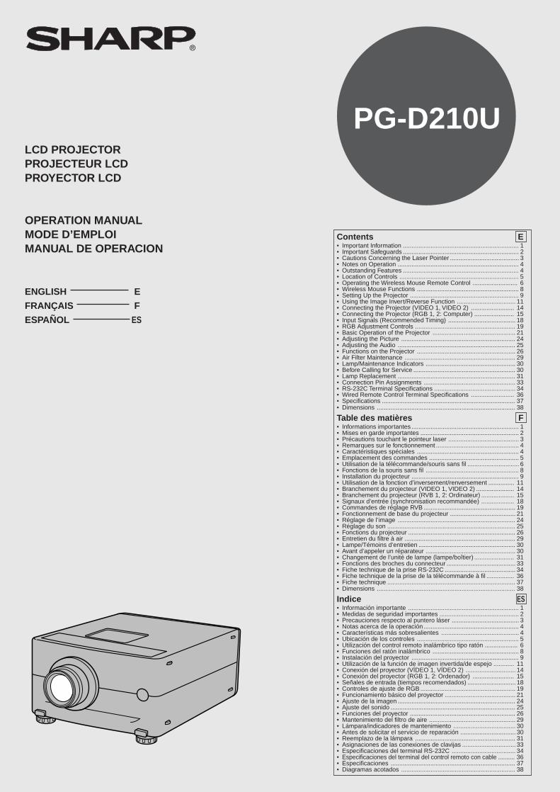
PG-D210ULCD PROJECTORPROJECTEUR LCDPROYECTOR LCD
OPERATION MANUALMODE D’EMPLOIMANUAL DE OPERACION
ENGLISH E
FRANÇAIS F
ESPAÑOL ES
Contents E• Important Information ................................................................... 1• Important Safeguards ................................................................... 2• Cautions Concerning the Laser Pointer ........................................ 3• Notes on Operation ...................................................................... 4• Outstanding Features ................................................................... 4• Location of Controls ..................................................................... 5• Operating the Wireless Mouse Remote Control .......................... 6• Wireless Mouse Functions ........................................................... 8• Setting Up the Projector ............................................................... 9• Using the Image Invert/Reverse Function .................................. 11• Connecting the Projector (VIDEO 1, VIDEO 2) ......................... 14• Connecting the Projector (RGB 1, 2: Computer) ....................... 15• Input Signals (Recommended Timing) ....................................... 18• RGB Adjustment Controls .......................................................... 19• Basic Operation of the Projector ................................................ 21• Adjusting the Picture .................................................................. 24• Adjusting the Audio .................................................................... 25• Functions on the Projector ......................................................... 26• Air Filter Maintenance ................................................................ 29• Lamp/Maintenance Indicators .................................................... 30• Before Calling for Service ........................................................... 30• Lamp Replacement .................................................................... 31• Connection Pin Assignments ..................................................... 33• RS-232C Terminal Specifications ............................................... 34• Wired Remote Control Terminal Specifications ......................... 36• Specifications ............................................................................. 37• Dimensions ................................................................................ 38
Table des matières F• Informations importantes .............................................................. 1• Mises en garde importantes ......................................................... 2• Précautions touchant le pointeur laser ......................................... 3• Remarques sur le fonctionnement ................................................ 4• Caractéristiques spéciales ........................................................... 4• Emplacement des commandes .................................................... 5• Utilisation de la télécommande/souris sans fil .............................. 6• Fonctions de la souris sans fil ...................................................... 8• Installation du projecteur .............................................................. 9• Utilisation de la fonction d’inversement/renversement ............... 11• Branchement du projecteur (VIDEO 1, VIDEO 2) ...................... 14• Branchement du projecteur (RVB 1, 2: Ordinateur) ................... 15• Signaux d’entrée (synchronisation recommandée) ................... 18• Commandes de réglage RVB ..................................................... 19• Fonctionnement de base du projecteur ...................................... 21• Réglage de l’image .................................................................... 24• Réglage du son .......................................................................... 25• Fonctions du projecteur .............................................................. 26• Entretien du filtre à air ................................................................ 29• Lampe/Témoins d’entretien ........................................................ 30• Avant d’appeler un réparateur .................................................... 30• Changement de l’unité de lampe (lampe/boîtier) ....................... 31• Fonctions des broches du connecteur ........................................ 33• Fiche technique de la prise RS-232C ......................................... 34• Fiche technique de la prise de la télécommande à fil ................ 36• Fiche technique .......................................................................... 37• Dimensions ................................................................................ 38
Indice ES• Información importante ................................................................ 1• Medidas de seguridad importantes .............................................. 2• Precauciones respecto al puntero láser ....................................... 3• Notas acerca de la operación ....................................................... 4• Características más sobresalientes ............................................. 4• Ubicación de los controles ........................................................... 5• Utilización del control remoto inalámbrico tipo ratón ................... 6• Funciones del ratón inalámbrico .................................................. 8• Instalación del proyector .............................................................. 9• Utilización de la función de imagen invertida/de espejo ............ 11• Conexión del proyector (VÍDEO 1, VÍDEO 2) ............................. 14• Conexión del proyector (RGB 1, 2: Ordenador) ........................ 15• Señales de entrada (tiempos recomendados) ............................ 18• Controles de ajuste de RGB ....................................................... 19• Funcionamiento básico del proyector ......................................... 21• Ajuste de la imagen .................................................................... 24• Ajuste del sonido ........................................................................ 25• Funciones del proyector ............................................................. 26• Mantenimiento del filtro de aire .................................................. 29• Lámpara/indicadores de mantenimiento .................................... 30• Antes de solicitar el servicio de reparación ................................ 30• Reemplazo de la lámpara .......................................................... 31• Asignaciones de las conexiones de clavijas ............................... 33• Especificaciones del terminal RS-232C ..................................... 34• Especificaciones del terminal del control remoto con cable .......... 36• Especificaciones ........................................................................ 37• Diagramas acotados .................................................................. 38
E-1
Dear SHARP Customer
Welcome to the SHARP Family. We are pleased that you are now the owner of a SHARP ColorLCD Projector built for outstanding quality, reliability and performance.Every SHARP Color LCD Projector is adjusted for a proper picture and has passed through themost stringent quality control tests at the factory. We have prepared this OPERATION MANUALso that you have the ability to adjust the picture and color to your personal viewing preference.We sincerely hope that you will be satisfied with the quality and performance of your Color LCDProjector for many years to come.Please read the instructions carefully, and keep them handy for future reference.
IMPORTANTFor your assistance in reporting the loss ortheft of your Color LCD Projector, pleaserecord the Serial Number located on the rearof the projector and retain this information.
Important Information
There are two important reasons for prompt warranty registration of your new SHARP LCDProjector, using the REGISTRATION CARD packed with the projector.1. WARRANTY
This is to assure that you immediately receive the full benefit of the parts, service andlabor warranty applicable to your purchase.
2. CONSUMER PRODUCT SAFETY ACTTo ensure that you will promptly receive any safety notification of inspection, modification,or recall that SHARP may be required to give under the 1972 Consumer Product SafetyAct, PLEASE READ CAREFULLY THE IMPORTANT “LIMITED WARRANTY” CLAUSE.
U.S.A. ONLY
WARNING: High brightness light source. Do not stare into the beam of light, or view directly.Be especially careful that children do not stare directly into the beam of light.
WARNING: To reduce the risk of fire or electric shock, do not expose this product to rain ormoisture.
CAUTION: TO REDUCE THE RISK OF ELECTRIC SHOCK,DO NOT REMOVE COVER.
NO USER-SERVICEABLE PARTS EXCEPT LAMP UNIT.REFER SERVICING TO QUALIFIED SERVICE
PERSONNEL.
The lightning flash with arrowhead symbol,within an equilateral triangle, is intended toalert the user to the presence of uninsulated“dangerous voltage” within the product’senclosure that may be of sufficientmagnitude to constitute a risk or electricshock to persons.
The exclamation point within a triangle isintended to alert the user to the presence ofimportant operating and maintenance(servicing) instructions in the literatureaccompanying the product.
CAUTION
Model No.: PG-D210U
Serial No.:
RISK OF ELECTRIC SHOCK.DO NOT REMOVE SCREWSEXCEPT SPECIFIED USER
SERVICE SCREW.

E-2
Important Safeguards
Electrical energy can perform many useful functions. This unit has been engineered and manufactured to ensureyour personal safety. But IMPROPER USE CAN RESULT IN POTENTIAL ELECTRICAL SHOCK OR FIRE HAZARD.In order not to defeat the safeguards incorporated into this LCD Projector, observe the following basic rules for itsinstallation, use and servicing. For your own protection and reliable usage of your LCD Projector, please be sure toread these “Important Safeguards” carefully before use.
1. Read Instructions—All the safety and operating instructions should be read before the product is operated.2. Retain Instructions—The safety and operating instructions should be retained for future reference.3. Heed Warnings—All warnings on the product and in the operating instructions should be adhered to.4. Follow Instructions—All operating and use instructions should be followed.5. Cleaning—Unplug this product from the wall outlet before cleaning. Do not use liquid cleaners or aerosol
cleaners. Use a damp cloth for cleaning.6. Attachments—Do not use attachments not recommended by the product manufacturer as they may cause
hazards.7. Water and Moisture—Do not use this product near water – for example, near a bathtub, wash bowl, kitchen
sink, or laundry tub; in a wet basement; or near a swimming pool; and the like.8. Accessories—Do not place this product on an unstable cart, stand, tripod, bracket, or table. The product
may fall, causing serious injury to a child or adult, and serious damage to the product. Use only with a cart,stand, tripod, bracket, or table recommended by the manufacturer, or sold with the product. Any mounting ofthe product should follow the manufacturer’s instructions, and should use a mounting accessory recom-mended by the manufacturer.
9. A product and cart combination should be moved with care. Quick stops, excessive force,and uneven surfaces may cause the product and cart combination to overturn.
10. Ventilation—Slots and openings in the cabinet are provided for ventilation to ensure reliable operation of theproduct and to protect it from overheating, and these openings must not be blocked or covered. The open-ings should never be blocked by placing the product on a bed, sofa, rug, or other similar surface. This prod-uct should not be placed in a built-in installation such as a bookcase or rack unless proper ventilation isprovided or the manufacturer’s instructions have been adhered to.
11. Power Sources—This product should be operated only from the type of power source indicated on themarking label. If you are not sure of the type of power supply to your home, consult your product dealer orlocal power company. For products intended to operate from battery power, or other sources, refer to theoperating instructions.
12. Grounding or Polarization—This product is equipped with a three-wire grounding-type plug, a plug having athird (grounding) pin. This plug will only fit into a grounding-type power outlet. This is a safety feature. If youare unable to insert the plug into the outlet, contact your electrician to replace your obsolete outlet. Do notdefeat the safety purpose of the grounding-type plug.
13. Power-Cord Protection—Power-supply cords should be routed so that they are not likely to be walked on orpinched by items placed upon or against them, paying particular attention to cords at plugs, conveniencereceptacles, and the point where they exit from the product.
WARNING: FCC Regulations state that any unauthorized changes or modifications to this equipment notexpressly approved by the manufacturer could void the user’s authority to operate this equipment.
The enclosed RGB signal cable and Macintosh adaptor must be used with the device. The cable and adaptorare provided to ensure that the device complies with FCC Class A verification.
INFORMATIONThis equipment has been tested and found to comply with the limits for a Class A digital device, pursuant to Part15 of the FCC Rules. These limits are designed to provide reasonable protection against harmful interferencewhen the equipment is operated in a commercial environment. This equipment generates, uses, and can radiateradio frequency energy and, if not installed and used in accordance with the instruction manual, may causeharmful interference to radio communications. Operation of this equipment in a residential area is likely to causeharmful interference, in which case the user will be required to correct the interference at his own expense.
U.S.A. ONLY
U.S.A. ONLY
U.S.A. ONLY
E-3
14. Lightning—For added protection for this product during a lightning storm, or when it is left unattended andunused for long periods of time, unplug it from the wall outlet and disconnect the cable system. This will pre-vent damage to the product due to lightning and power-line surges.
15. Overloading—Do not overload wall outlets, extension cords, or integral convenience receptacles as this canresult in a risk of fire or electric shock.
16. Object and Liquid Entry—Never push objects of any kind into this product through openings as they maytouch dangerous voltage points or short-out parts that could result in a fire or electric shock. Never spillliquid of any kind on the product.
17. Servicing—Do not attempt to service this product yourself as opening or removing covers may expose you todangerous voltage or other hazards. Refer all servicing to qualified service personnel.
18. Damage Requiring Service—Unplug this product from the wall outlet and refer servicing to qualified servicepersonnel under the following conditions:
a. When the power-supply cord or plug is damaged.b. If liquid has been spilled, or objects have fallen into the product.c. If the product has been exposed to rain or water.d. If the product does not operate normally by following the operating instructions. Adjust only those con-
trols that are covered by the operating instructions, as an improper adjustment of other controls mayresult in damage and will often require extensive work by a qualified technician to restore the product tonormal operation.
e. If the product has been dropped or damaged in any way.f. When the product exhibits a distinct change in performance—this indicates a need for service.
19. Replacement Parts—When replacement parts are required, be sure the service technician has used replace-ment parts specified by the manufacturer or with the same characteristics as the original part. Unauthorizedsubstitutions may result in fire, electric shock, or other hazards.
20. Safety Check—Upon completion of any service or repairs to this product, ask the service technician to per-form safety checks to determine that the product is in proper operating condition.
21. Wall or Ceiling Mounting—The product should be mounted to a wall or ceiling only as recommended by themanufacturer.
22. Heat—The product should be situated away from heat sources such as radiators, heat registers, stoves, orother products (including amplifiers) that produce heat.
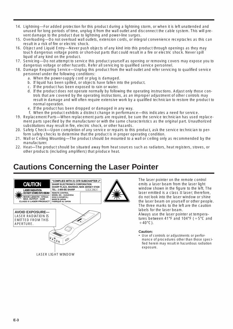
Cautions Concerning the Laser Pointer
CAUTIONLASER RADIATION-DO NOT STARE INTO BEAMWAVE LENGTH : 670nmMAX. OUTPUT : 1mW
CLASS II LASER PRODUCT
"COMPLIES WITH 21 CFR SUBCHAPTER J"SHARP ELECTRONICS CORPORATIONSHARP PLAZA, MAHWAH, NEW JERSEY 07430TEL : 1-800-BE-SHARP U.S.A. ONLY
REMOTE CONTROLMODEL NO. : G1414CESADC6V (1.5VX4PCS.)MADE IN JAPANFABRIQUÉ AU JAPON
AVOID EXPOSURE—LASER RADIATION ISEMITTED FROM THISAPERTURE.
LASER LIGHT WINDOW
The laser pointer on the remote controlemits a laser beam from the laser lightwindow shown in the figure to the left. Thelaser emitted is a class II laser; therefore,do not look into the laser window or shinethe laser beam on yourself or other people.The three marks to the left are the cautionlabels for the laser beam.Always use the laser pointer at tempera-tures between 41°F and 104°F (`5°C and`40°C).
Caution:• Use of controls or adjustments or perfor-
mance of procedures other than those speci-fied herein may result in hazardous radiationexposure.

E-4
Notes on Operation
About the Temperature Monitor Function:• If the projector starts to overheat due to set-up problems or a dirty air filter, “TEMP.” will flash
in the upper-left corner of the picture. If the temperature continues to rise, then the lamp willturn off, the TEMPERATURE WARNING indicator will flash, and after a 90-second cooling-offperiod the power will shut off. Refer to page 30, “Maintenance Indicators,” when the “TEMP.”warning appears in the picture.
• The cooling fan regulates the internal temperature, and its performance is automaticallycontrolled. The sound of the fan may change during operation due to changes in the fanspeed.
TEMP.
Outstanding Features
Allows easy projection of large screen, full-color com-puter and video images.• Can be projected directly onto a video screen or white
wall.• Lightweight, convergence-free system for easy installa-
tion.DIRECT COMPUTER COMPATIBILITYA multi-scan RGB Input accepts signals from SXGA(1,280 dots 2 1,024 lines compressed), XGA (1,024 dots2 768 lines), SVGA (800 dots 2 600 lines), VGA(640 dots 2 480 lines) and Mac (1,024 dots 2 768 linesmaximum) compatible computers without the need forany additional hardware.HIGH PICTURE QUALITYThe three LCD panels contain 786,432 2 RGB pixels toachieve exceptionally bright, high quality images.INTELLIGENT COMPRESSIONSXGA images are compressed and projected withoutimage data loss.VERSATILE REMOTE CONTROL• Built-in wireless mouse allows simultaneous operation
of projector and computer.• Built-in Laser Pointer for professional presentations.FLEXIBLE USE• In addition to the standard front projection mode, the
menu driven functions can be used to instantly reversethe image for rear projection, and invert the image forceiling mounting.
• Screen projection size adjusts from 40 to 300 inches.BUILT-IN STEREO SPEAKERSBuilt in 2 W ` 2 W stereo amplifiers and speakers elimi-nate the need for external audio components.USE WITH “PLUG AND PLAY”“Plug and Play” compatible with VESA DDC 1 andDDC 2B standards.
E-5
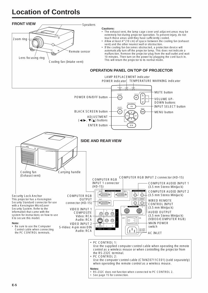
Location of Controls
FRONT VIEWCautions:• The exhaust vent, the lamp cage cover and adjacent areas may be
extremely hot during projector operation. To prevent injury, do nottouch these areas until they have sufficiently cooled.
• Allow at least 4 ( (10 cm) of space between the cooling fan (exhaustvent) and the other nearest wall or obstruction.
• If the cooling fan becomes obstructed, a protection device willautomatically turn off the projector lamp. This does not indicate amalfunction. Remove the projector plug from the wall outlet and wait10 minutes. Then turn on the power by plugging the cord back in.This will return the projector to its normal mode.
Remote sensor
Speakers
ENTER
BLACKSCREEN
ON/OFF
POWER LAMP TEMP.
MUTE
INPUT SELECT
VOL
MENU
POWER indicator TEMPERATURE WARNING indicatorLAMP REPLACEMENT indicator
MUTE button
VOLUME UP-DOWN buttons
MENU button
INPUT SELECT button
Lens focusing ringCooling fan (Intake vent)
Zoom ring
ENTER button
ADJUSTMENT(ß/©, ƒ/∂) buttons
BLACK SCREEN button
POWER ON/OFF button
OPERATION PANEL ON TOP OF PROJECTOR
COMPUTER AUDIO
PC CONTROL
COMPUTER RGB
VIDEO
S-VIDEO
1 2
L
OFF ON
R
L R
AUDIO
IN2
IN1
AUDIOOUTPUT
IN 1
OUT
IN 2
WIREDREMOTE
IN 1 IN 2
110-120V/200-240V~
VIDEO INPUT 1COMPOSITE
Video: RCAAudio: RCA
• PC CONTROL 1:Use the supplied computer control cable when operating the remotecontrol as a wireless mouse or when controlling the projector fromthe RS-232C terminal.
• PC CONTROL 2:Use the computer control cable (CTANZ0711CE01) (sold separately)when operating the remote control as a wireless mouse.
Notes:• RS-232C does not function when connected to PC CONTROL 2.• See page 15 for connection.
COMPUTER RGBINPUT 1 connector(HD-15)
COMPUTER AUDIO INPUT 1(3.5 mm Stereo Minijack)
COMPUTER RGB INPUT 2 connector (HD-15)
AUDIO OUTPUT(3.5 mm Stereo Minijack)(VIDEO/COMPUTER RGB)
AC INLET
MAIN POWERswitch
COMPUTER RGBOUTPUT
connector (HD-15)
Cooling fan(Exhaust vent)
Security Lock AnchorThis projector has a KensingtonSecurity Standard connector for usewith a Kensington MicroSaverSecurity System. Refer to theinformation that came with thesystem for instructions on how to useit to secure this model.
Note:• Be sure to use the Computer
Control cable when connectingthe PC CONTROL terminals.
Carrying handle
VIDEO INPUT 2S-Video: 4-pin mini DIN
Audio: RCA
COMPUTER AUDIO INPUT 2(3.5 mm Stereo Minijack)
WIRED REMOTECONTROL INPUT(3.5 mm Minijack)
SIDE AND REAR VIEW
E-6
Position of MOUSE/ADJUSTMENT switch
BLACK SCREEN (RED)
ON (RED)
ADJ.MENU (RED)
ENTER (RED)
ADJ. ß/©, ƒ/∂ (NOT LIT)
—
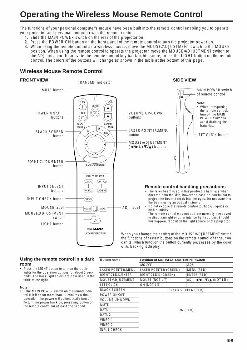
Operating the Wireless Mouse Remote Control
The functions of your personal computer’s mouse have been built into the remote control enabling you to operateyour projector and personal computer with the remote control.
1. Slide the MAIN POWER switch on the rear of the projector on.2. Press the POWER ON button on the front panel of the remote control to turn the projector power on.3. When using the remote control as a wireless mouse, move the MOUSE/ADJUSTMENT switch to the MOUSE
position. When using the remote control to operate the projector, move the MOUSE/ADJUSTMENT switch tothe ADJ. position. To activate the remote control key back-light feature, press the LIGHT button on the remotecontrol. The colors of the buttons will change as shown in the table at the bottom of this page.
ONMUTE
MNB
BLACKSCREEN
R-CLICK/ENTER
INPUT SELECT
DATA1
CHECK
MOUSE
LIGHT
LCD PROJECTOR
ADJ.
DATA2
VIDEO1 VIDEO2
LASER/ MENU
VOL
OFF
R/C
OF
FO
N
Wireless Mouse Remote Control
FRONT VIEW
ADJ. labelMOUSE label
TRANSMIT indicator
MUTE button
BLACK SCREENbutton
RIGHT-CLICK/ENTERbutton
INPUT SELECTbuttons
INPUT CHECK button
MOUSE/ADJUSTMENTswitch
LIGHT button
VOLUME UP-DOWNbuttons
LASER POINTER/MENUbutton
MOUSE/ADJUSTMENT(ß/©), (ƒ/∂) buttons
Note:• When transporting
the remote control,turn off the MAINPOWER switch toavoid draining thebatteries.
LEFT-CLICK button
Using the remote control in a darkroom• Press the LIGHT button to turn on the back-
lights for the operation buttons for about 5 sec-onds. The back-light colors are described in thetable to the right.
Note:• If the MAIN POWER switch on the remote con-
trol is left on for more than 10 minutes withoutoperation, the power will automatically turn off.To turn the power back on, press any button onthe remote control for at least one second.
SIDE VIEW
POWER ON/OFFbuttons
MOUSELASER POINTER (GREEN)
RIGHT-CLICK (GREEN)
MOUSE (NOT LIT)
ON (NOT LIT)
Button name
LASER POINTER/MENU
RIGHT-CLICK/ENTER
MOUSE/ADJUSTMENT
LEFT-CLICK
BLACK SCREEN
POWER ON/OFF
VOLUME UP-DOWN
MUTE
DATA 1
DATA 2
VIDEO 1
VIDEO 2
INPUT CHECK
When you change the setting of the MOUSE/ADJUSTMENT switch,the functions of certain buttons on the remote control change. Youcan tell which function the button currently possesses by the colorof its back-light display.
Remote control handling precautions• The laser beam used in this product is harmless when
directed onto the skin, however please be careful not toproject the beam directly into the eyes. Do not stare intothe beam using an optical instrument.
• Do not expose the remote control to shocks, liquids orhigh humidity.The remote control may not operate normally if exposedto direct sunlight or other intense light sources. Shouldthis happen, reposition the light source or the projector.
MAIN POWER switchof remote control
E-7
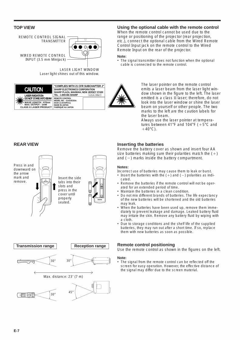
Inserting the batteriesRemove the battery cover as shown and insert four AAsize batteries making sure their polarities match the (`)and (1) marks inside the battery compartment.
Notes:Incorrect use of batteries may cause them to leak or burst.• Insert the batteries with the (`) and (1) polarities as indi-
cated.• Remove the batteries if the remote control will not be oper-
ated for an extended period of time.• Maintain the batteries in a clean condition.• Do not mix different brands of batteries. The life expectancy
of the new batteries will be shortened and the old batteriesmay leak.
• When the batteries have been used up, remove them imme-diately to prevent leakage and damage. Leaked battery fluidmay irritate the skin. Remove any battery fluid by wiping witha cloth.
• Due to storage conditions and the shelf life of the suppliedbatteries, they may run out after a short time. If so, replacethem with new batteries as soon as possible.
Remote control positioningUse the remote control as shown in the figures on the left.
Note:• The signal from the remote control can be reflected off the
screen for easy operation. However, the effective distance ofthe signal may differ due to the screen material.
Transmission range
30°
Press in anddownward onthe arrowmark andremove.
Using the optional cable with the remote controlWhen the remote control cannot be used due to therange or positioning of the projector (rear projection,etc.), connect the optional cable from the Wired RemoteControl Input jack on the remote control to the WiredRemote Input on the rear of the projector.
Note:• The signal transmitter does not function when the optional
cable is connected to the remote control.
TOP VIEW
Insert the sidetabs into theirslots andpress in thecover untilproperlyseated.
30°
30°45°
Max. distance: 23* (7 m)
Reception range
REMOTE CONTROL SIGNALTRANSMITTER
LASER LIGHT WINDOWLaser light shines out of this window.
CAUTIONLASER RADIATION-DO NOT STARE INTO BEAMWAVE LENGTH : 670nmMAX. OUTPUT : 1mW
CLASS II LASER PRODUCT
"COMPLIES WITH 21 CFR SUBCHAPTER J"SHARP ELECTRONICS CORPORATIONSHARP PLAZA, MAHWAH, NEW JERSEY 07430TEL : 1-800-BE-SHARP U.S.A. ONLY
REMOTE CONTROLMODEL NO. : G1414CESADC6V (1.5VX4PCS.)MADE IN JAPANFABRIQUÉ AU JAPON
The laser pointer on the remote controlemits a laser beam from the laser light win-dow shown in the figure to the left. The laseremitted is a class II laser; therefore, do notlook into the laser window or shine the laserbeam on yourself or other people. The twomarks to the left are the caution labels forthe laser beam.Always use the laser pointer at tempera-tures between 41°F and 104°F (`5°C and`40°C).
REAR VIEW
WIRED REMOTE CONTROLINPUT (3.5 mm Minijack)

E-8
Wireless Mouse Functions
Connection Example The wireless mouse functions and laser pointer on theremote control can help you create a more professionalpresentation.• By connecting the supplied computer control cable to the
PC CONTROL terminal on your projector and the suppliedmouse control cables to the mouse terminal on yourpersonal computer, you can use the wireless mouse on theremote control, instead of the mouse equipped with yourpersonal computer, to operate your personal computer.The wireless mouse functions will work with personalcomputers compatible with IBM PS/2, serial (RS-232C) orApple ADB type mouse systems.
POWER ON/OFFbuttons
ONMUTE
MNB
BLACKSCREEN
R-CLICK/ENTER
INPUT SELECT
DATA1
CHECK
MOUSE
LIGHT
LCD PROJECTOR
ADJ.
DATA2
VIDEO1 VIDEO2
LASER/ MENU
VOL
OFF
LASER POINTER button
MOUSE/ADJUSTMENTswitch
Functions and Operations
MOUSE buttons
COMPUTER AUDIO
PC CONTROL
COMPUTER RGB
VIDEO
S-VIDEO
1 2
L
OFF ON
R
L R
AUDIO
IN2
IN1
AUDIOOUTPUT
IN 1
OUT
IN 2
WIREDREMOTE
IN 1 IN 2
110-120V/200-240V~
Rear terminals
Personal computer
To mouse terminal
Supplied mouse control cable (for IBMPS/2, serial and Apple ADB type mouse)
R/C
OF
FO
N
MAIN POWER switch of remote control
LEFT-CLICK button
The laser pointer on the remote control emitsa laser beam from the laser light window. Thelaser emitted is a class II laser; therefore, donot look into the laser window or shine thelaser beam on yourself or other people. Thetwo marks to the left are the caution labels forthe laser beam.Always use the laser pointer at temperaturesbetween 41°F and 104°F (`5°C and`40°C).
CAUTIONLASER RADIATION-DO NOT STARE INTO BEAMWAVE LENGTH : 670nmMAX. OUTPUT : 1mW
CLASS II LASER PRODUCT
"COMPLIES WITH 21 CFR SUBCHAPTER J"SHARP ELECTRONICS CORPORATIONSHARP PLAZA, MAHWAH, NEW JERSEY 07430TEL : 1-800-BE-SHARP U.S.A. ONLY
REMOTE CONTROLMODEL NO. : G1414CESADC6V (1.5VX4PCS.)MADE IN JAPANFABRIQUÉ AU JAPON
Suppliedcomputercontrol cable
• First, connect the units as shown above, and turn the projector power on.• Second, turn the computer power on.• Next, slide the MAIN POWER switch on the side of the remote control.• When using the remote control as a wireless mouse, move the MOUSE/ADJUSTMENT switch to the MOUSE position.
Notes:• In some situations the wireless mouse may be inoperable if your computer port is not correctly set-up. Please refer to your computer owners
manual for details on setting-up/installing the correct mouse driver.• Be sure to use the computer control cable when connecting the PC CONTROL terminals.• Do not connect or remove the mouse control cables and computer control cable to/from your computer while it is on. This may damage your
computer.• Only one set of connection cables is supplied with your projector. For additional connection cables, contact your nearest Authorized Sharp
Industrial LCD Products Dealer or Service Center.• Do not connect the mouse input terminal for IBM/Mac and the mouse input terminal for PC98 simultaneously.
MOUSE buttonsBy lightly pressing the up/down and right/left arrow buttons located on the front of the remotecontrol, you can move the mouse cursor on your monitor screen.
Note:• The amount of pressure applied to the MOUSE button determines the speed the mouse cursor travels. Pressing
lightly on the periphery of the MOUSE button makes the mouse cursor move slowly. Pressing hard makes it movequickly.
LEFT-CLICK button The LEFT-CLICK button on the back of the remote control corresponds to the left buttonof the mouse on two-button mouse systems.
RIGHT-CLICK button The RIGHT-CLICK button on the front of the remote control corresponds to the rightbutton on two-button mouse systems.Note: For one-button mouse systems use either the LEFT-CLICK or RIGHT-CLICK button.
LASER POINTER button Press the LASER POINTER button to activate the laser pointer.When the button is pressed, the light stays on; when the button is released, the lightgoes off. However, even when the button is pressed continuously, the light automati-cally goes off 1 minute after it goes on. To turn it on again press the laser pointer buttonone more time.
Mouse cursor
RIGHT-CLICK button
E-9
Setting Up the Projector
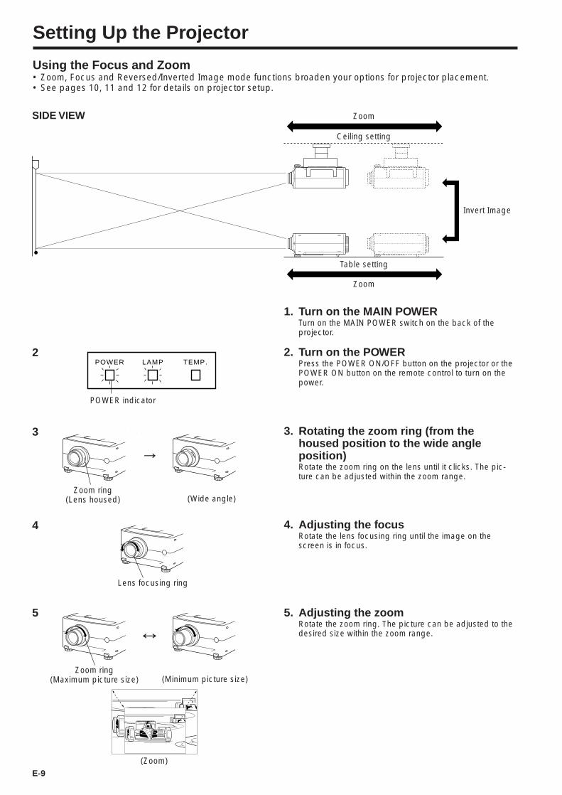
Using the Focus and Zoom• Zoom, Focus and Reversed/Inverted Image mode functions broaden your options for projector placement.• See pages 10, 11 and 12 for details on projector setup.
SIDE VIEW
1. Turn on the MAIN POWERTurn on the MAIN POWER switch on the back of theprojector.
2. Turn on the POWERPress the POWER ON/OFF button on the projector or thePOWER ON button on the remote control to turn on thepower.
Table setting
Zoom
3. Rotating the zoom ring (from thehoused position to the wide angleposition)Rotate the zoom ring on the lens until it clicks. The pic-ture can be adjusted within the zoom range.
4. Adjusting the focusRotate the lens focusing ring until the image on thescreen is in focus.
5. Adjusting the zoomRotate the zoom ring. The picture can be adjusted to thedesired size within the zoom range.
Zoom
Ceiling setting
Invert Image
3
→
(Wide angle)Zoom ring
(Lens housed)
(Minimum picture size)
(Zoom)
↔5
Zoom ring(Maximum picture size)
Lens focusing ring
4
2POWER LAMP TEMP.
POWER indicator
E-10
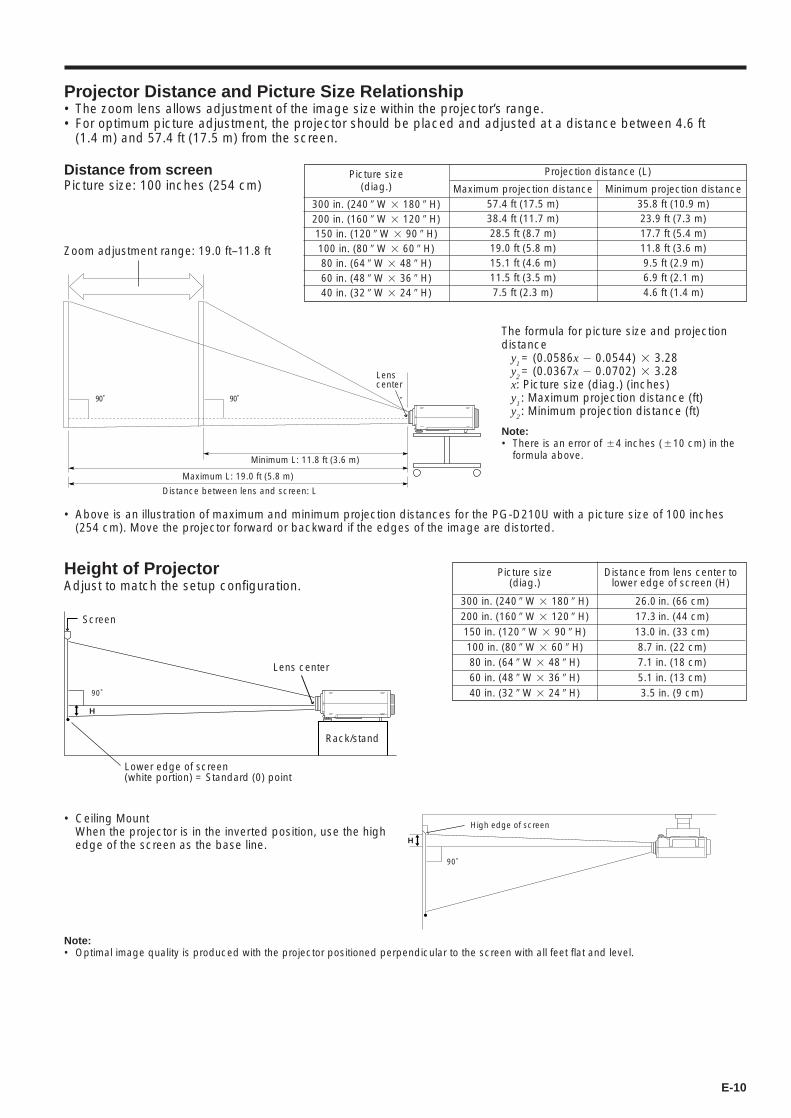
Height of ProjectorAdjust to match the setup configuration.
Projector Distance and Picture Size Relationship• The zoom lens allows adjustment of the image size within the projector’s range.• For optimum picture adjustment, the projector should be placed and adjusted at a distance between 4.6 ft
(1.4 m) and 57.4 ft (17.5 m) from the screen.
Maximum projection distance57.4 ft (17.5 m)38.4 ft (11.7 m)28.5 ft (8.7 m)19.0 ft (5.8 m)15.1 ft (4.6 m)11.5 ft (3.5 m)7.5 ft (2.3 m)
Minimum projection distance35.8 ft (10.9 m)23.9 ft (7.3 m)17.7 ft (5.4 m)11.8 ft (3.6 m)9.5 ft (2.9 m)6.9 ft (2.1 m)4.6 ft (1.4 m)
Projection distance (L)Picture size(diag.)
300 in. (240 9 W 2 180 9 H)200 in. (160 9 W 2 120 9 H)150 in. (120 9 W 2 90 9 H)100 in. (80 9 W 2 60 9 H)80 in. (64 9 W 2 48 9 H)60 in. (48 9 W 2 36 9 H)40 in. (32 9 W 2 24 9 H)
Maximum L: 19.0 ft (5.8 m)
Minimum L: 11.8 ft (3.6 m)
Distance between lens and screen: L
Lenscenter
90˚ 90˚
300 in. (240 9 W 2 180 9 H)200 in. (160 9 W 2 120 9 H)150 in. (120 9 W 2 90 9 H)100 in. (80 9 W 2 60 9 H)80 in. (64 9 W 2 48 9 H)60 in. (48 9 W 2 36 9 H)40 in. (32 9 W 2 24 9 H)
26.0 in. (66 cm)17.3 in. (44 cm)13.0 in. (33 cm)8.7 in. (22 cm)7.1 in. (18 cm)5.1 in. (13 cm)3.5 in. (9 cm)
Distance from lens center tolower edge of screen (H)
Distance from screenPicture size: 100 inches (254 cm)
Zoom adjustment range: 19.0 ft–11.8 ft
• Above is an illustration of maximum and minimum projection distances for the PG-D210U with a picture size of 100 inches(254 cm). Move the projector forward or backward if the edges of the image are distorted.
Picture size(diag.)
The formula for picture size and projectiondistance
y1 = (0.0586x 1 0.0544) 2 3.28
y2 = (0.0367x 1 0.0702) 2 3.28
x: Picture size (diag.) (inches)y
1: Maximum projection distance (ft)
y2: Minimum projection distance (ft)
Note:• There is an error of 54 inches (510 cm) in the
formula above.
Lens center
H
90˚
Rack/stand
90˚
High edge of screen
H
• Ceiling MountWhen the projector is in the inverted position, use the highedge of the screen as the base line.
Note:• Optimal image quality is produced with the projector positioned perpendicular to the screen with all feet flat and level.
Screen
Lower edge of screen(white portion) = Standard (0) point
E-11
Using the Image Invert/Reverse Function
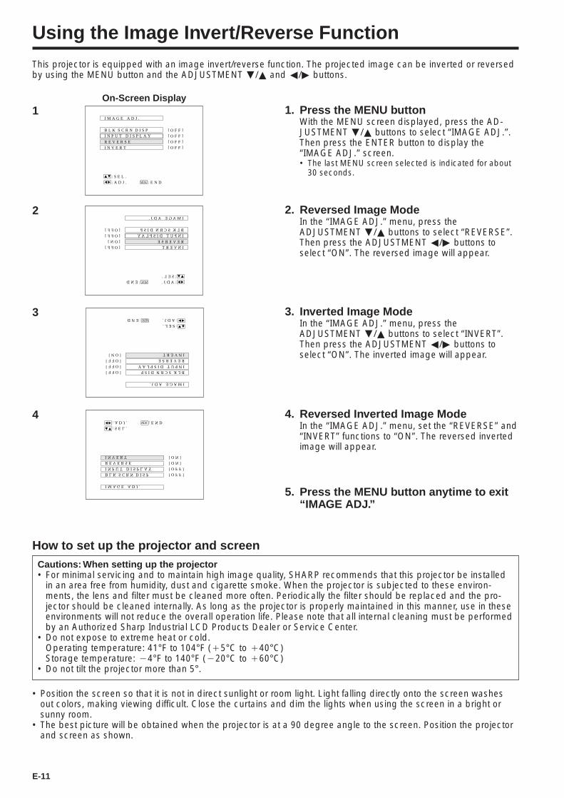
This projector is equipped with an image invert/reverse function. The projected image can be inverted or reversedby using the MENU button and the ADJUSTMENT ƒ/∂ and ß/© buttons.
1
B L K S C R N D I S P
I M A G E A D J .
R E V E R S E
I N V E R T
I N P U T D I S P L A Y [ O F F ]
[ O F F ]
[ O F F ]
[ O F F ]
: S E L .
: A D J . : E N DMENU
BLK SCRN DISP
IMAGE ADJ.
REVERSE
INVERT
INPUT DISPLAY[OFF]
[ON]
[OFF]
[OFF]
:SEL.
:ADJ.:END MENU
2 2. Reversed Image ModeIn the “IMAGE ADJ.” menu, press theADJUSTMENT ƒ/∂ buttons to select “REVERSE”.Then press the ADJUSTMENT ß/© buttons toselect “ON”. The reversed image will appear.
BLK SCRN DISP
IMAGE ADJ.
REVERSE
INVERT
INPUT DISPLAY[OFF]
[OFF]
[ON]
[OFF]
:SEL.
:ADJ.:END MENU
3 3. Inverted Image ModeIn the “IMAGE ADJ.” menu, press theADJUSTMENT ƒ/∂ buttons to select “INVERT”.Then press the ADJUSTMENT ß/© buttons toselect “ON”. The inverted image will appear.
B L K S C R N D I S P
I M A G E A D J .
R E V E R S E
I N V E R T
I N P U T D I S P L A Y [ O F F ]
[ O N ]
[ O N ]
[ O F F ]
: S E L .
: A D J . : E N DMENU4 4. Reversed Inverted Image Mode
In the “IMAGE ADJ.” menu, set the “REVERSE” and“INVERT” functions to “ON”. The reversed invertedimage will appear.
5. Press the MENU button anytime to exit“IMAGE ADJ.”
1. Press the MENU buttonWith the MENU screen displayed, press the AD-JUSTMENT ƒ/∂ buttons to select “IMAGE ADJ.”.Then press the ENTER button to display the“IMAGE ADJ.” screen.• The last MENU screen selected is indicated for about
30 seconds.
Cautions: When setting up the projector• For minimal servicing and to maintain high image quality, SHARP recommends that this projector be installed
in an area free from humidity, dust and cigarette smoke. When the projector is subjected to these environ-ments, the lens and filter must be cleaned more often. Periodically the filter should be replaced and the pro-jector should be cleaned internally. As long as the projector is properly maintained in this manner, use in theseenvironments will not reduce the overall operation life. Please note that all internal cleaning must be performedby an Authorized Sharp Industrial LCD Products Dealer or Service Center.
• Do not expose to extreme heat or cold.Operating temperature: 41°F to 104°F (`5°C to `40°C)Storage temperature: 14°F to 140°F (120°C to `60°C)
• Do not tilt the projector more than 5°.
How to set up the projector and screen
• Position the screen so that it is not in direct sunlight or room light. Light falling directly onto the screen washesout colors, making viewing difficult. Close the curtains and dim the lights when using the screen in a bright orsunny room.
• The best picture will be obtained when the projector is at a 90 degree angle to the screen. Position the projectorand screen as shown.
On-Screen Display
E-12
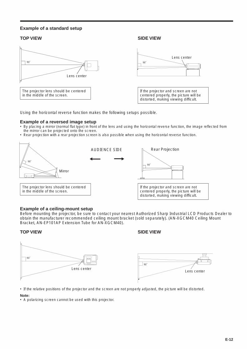
Example of a ceiling-mount setupBefore mounting the projector, be sure to contact your nearest Authorized Sharp Industrial LCD Products Dealer toobtain the manufacturer recommended ceiling mount bracket (sold separately). (AN-XGCM40 Ceiling MountBracket, AN-EP101AP Extension Tube for AN-XGCM40).
TOP VIEW
• If the relative positions of the projector and the screen are not properly adjusted, the picture will be distorted.
Example of a standard setup
TOP VIEW
If the projector and screen are notcentered properly, the picture will bedistorted, making viewing difficult.
90˚ 90˚
Lens center
Lens center
90˚
SIDE VIEW
The projector lens should be centeredin the middle of the screen.
If the projector and screen are notcentered properly, the picture will bedistorted, making viewing difficult.
Lens center
Using the horizontal reverse function makes the following setups possible.
Example of a reversed image setup• By placing a mirror (normal flat type) in front of the lens and using the horizontal reverse function, the image reflected from
the mirror can be projected onto the screen.• Rear projection with a rear projection screen is also possible when using the horizontal reverse function.
AUDIENCE SIDE
Mirror
90˚
The projector lens should be centeredin the middle of the screen.
Rear Projection
90˚
SIDE VIEW
Lens center
90˚
Note:• A polarizing screen cannot be used with this projector.
E-13
2
1
Adjuster release
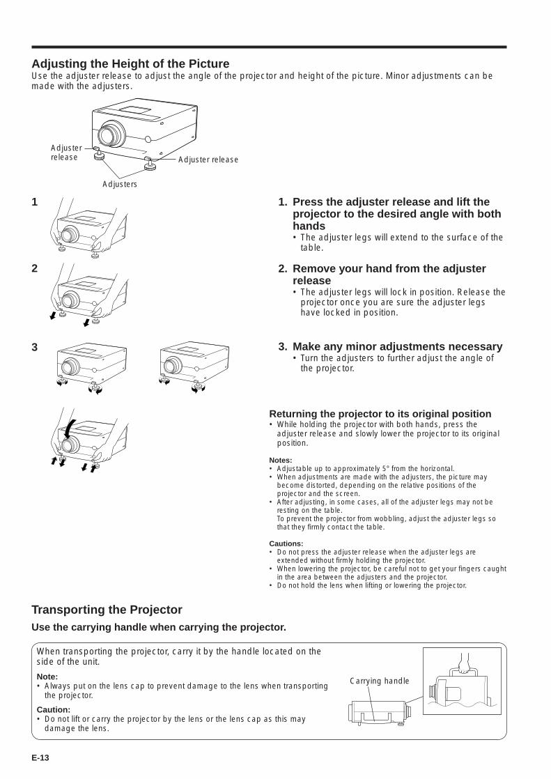
Adjusting the Height of the PictureUse the adjuster release to adjust the angle of the projector and height of the picture. Minor adjustments can bemade with the adjusters.
1. Press the adjuster release and lift theprojector to the desired angle with bothhands• The adjuster legs will extend to the surface of the
table.
2. Remove your hand from the adjusterrelease• The adjuster legs will lock in position. Release the
projector once you are sure the adjuster legshave locked in position.
3. Make any minor adjustments necessary• Turn the adjusters to further adjust the angle of
the projector.
Adjusterrelease
Adjusters
3
Carrying handle
When transporting the projector, carry it by the handle located on theside of the unit.
Note:• Always put on the lens cap to prevent damage to the lens when transporting
the projector.
Caution:• Do not lift or carry the projector by the lens or the lens cap as this may
damage the lens.
Transporting the ProjectorUse the carrying handle when carrying the projector.
Returning the projector to its original position• While holding the projector with both hands, press the
adjuster release and slowly lower the projector to its originalposition.
Notes:• Adjustable up to approximately 5° from the horizontal.• When adjustments are made with the adjusters, the picture may
become distorted, depending on the relative positions of theprojector and the screen.
• After adjusting, in some cases, all of the adjuster legs may not beresting on the table.To prevent the projector from wobbling, adjust the adjuster legs sothat they firmly contact the table.
Cautions:• Do not press the adjuster release when the adjuster legs are
extended without firmly holding the projector.• When lowering the projector, be careful not to get your fingers caught
in the area between the adjusters and the projector.• Do not hold the lens when lifting or lowering the projector.
E-14
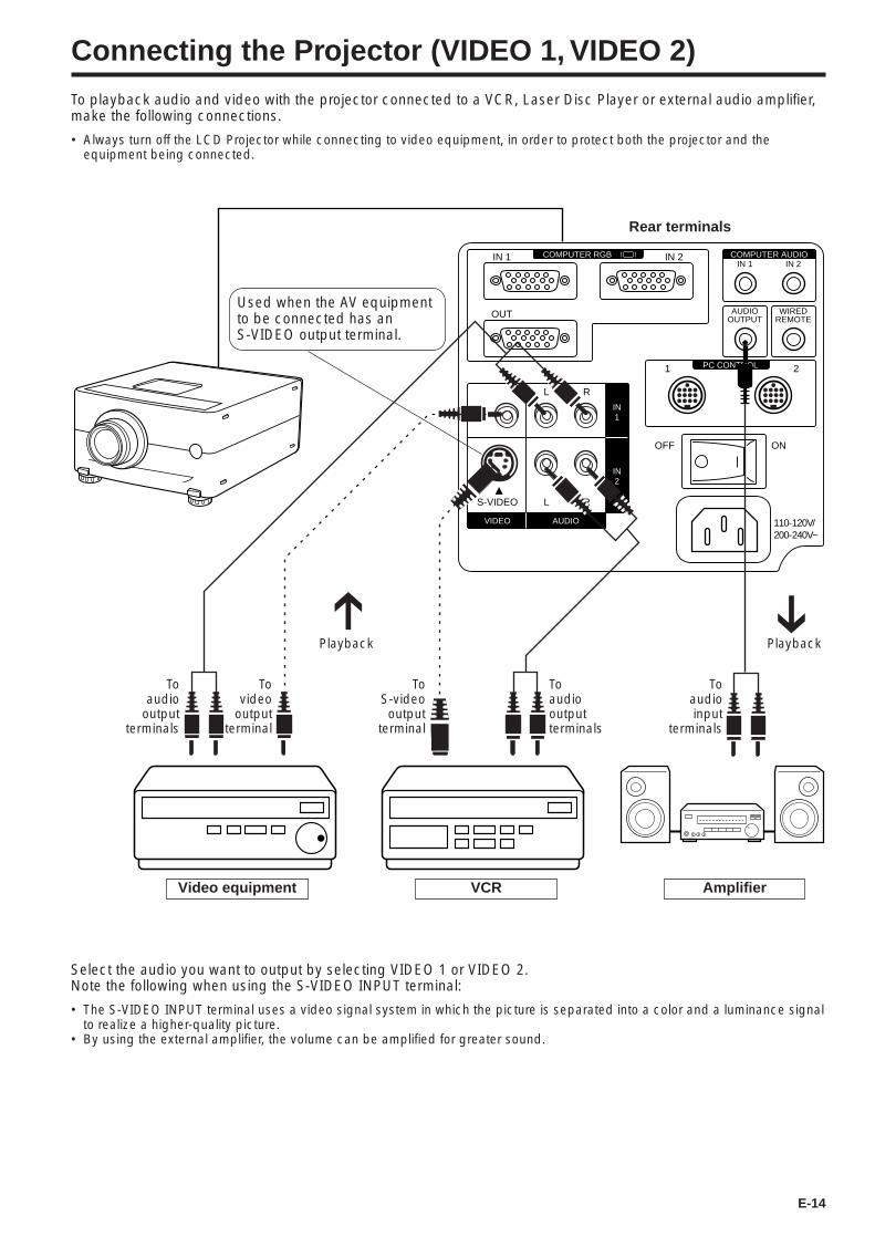
Connecting the Projector (VIDEO 1, VIDEO 2)
To playback audio and video with the projector connected to a VCR, Laser Disc Player or external audio amplifier,make the following connections.
• Always turn off the LCD Projector while connecting to video equipment, in order to protect both the projector and theequipment being connected.
Amplifier
Toaudio
outputterminals
ToS-videooutput
terminal
Toaudiooutputterminals
Toaudioinput
terminals
Video equipment VCR
Rear terminals
Tovideo
outputterminal
Used when the AV equipmentto be connected has anS-VIDEO output terminal.
PlaybackPlayback
Select the audio you want to output by selecting VIDEO 1 or VIDEO 2.Note the following when using the S-VIDEO INPUT terminal:
• The S-VIDEO INPUT terminal uses a video signal system in which the picture is separated into a color and a luminance signalto realize a higher-quality picture.
• By using the external amplifier, the volume can be amplified for greater sound.
COMPUTER AUDIO
PC CONTROL
COMPUTER RGB
VIDEO
S-VIDEO
1 2
L
OFF ON
R
L R
AUDIO
IN2
IN1
AUDIOOUTPUT
IN 1
OUT
IN 2
WIREDREMOTE
IN 1 IN 2
110-120V/200-240V~
E-15
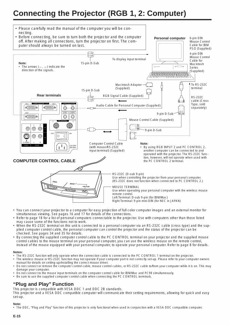
Connecting the Projector (RGB 1, 2: Computer)
COMPUTER AUDIO
PC CONTROL
COMPUTER RGB
VIDEO
S-VIDEO
1 2
L
OFF ON
R
L R
AUDIO
IN2
IN1
AUDIOOUTPUT
IN 1
OUT
IN 2
WIREDREMOTE
IN 1 IN 2
110-120V/200-240V~
15-pin D-Sub
RGB Signal Cable (Supplied)
Audio Cable for Personal Computer (Supplied)
Rear terminals
• Please carefully read the manual of the computer you will be con-necting.
• Before connecting, be sure to turn both the projector and the computeroff. After making all connections, turn the projector on first. The com-puter should always be turned on last.
Personal computer 6-pin DINMouse ControlCable for IBMPS/2 (Supplied)
4-pin DINMouse ControlCable forMacintoshSeries(Supplied)
Macintosh Adaptor(Supplied)
To RS-232Cterminal
RS-232Ccable (CrossType, soldseparately)
15-pin D-Sub
Computer Control Cable(with mouse/RS-232Cinput terminal) (Supplied)
Note:• By using RGB INPUT 2 and PC CONTROL 2,
another computer can be connected to andoperated with the projector. The RS-232C func-tion, however, will not operate when used withthe PC CONTROL 2 terminal.
Note:• The arrows (←, ↔) indicate the
direction of the signals.
RS-232C (D-sub 9-pin)Use when controlling the projector from your personal computer.(RS-232C does not function when connected to PC CONTROL 2.)
MOUSE TERMINALUse when operating your personal computer with the wireless mouseremote control.Left Terminal: D-sub 9-pin (for IBM/Mac)Right Terminal: 9-pin mini DIN (for NEC in JAPAN)
Mouse Control Cable (Supplied)
9-pin D-Sub
9-pin D-Sub
To display input terminal
COMPUTER CONTROL CABLE
• You can connect your projector to a computer for easy projection of full color computer images and an external monitor forsimultaneous viewing. See pages 16 and 17 for details of the connections.
• Refer to page 18 for a list of personal computers connectable to the projector. Use with computers other than those listedmay cause some of the functions not to work.
• When the RS-232C terminal on this unit is connected to a personal computer via an RS-232C cable (cross type) and the sup-plied computer control cable, the personal computer can control the projector and the status of the projector can bechecked. See pages 34 and 35 for details.
• By connecting the supplied computer control cable to the PC CONTROL terminal on your projector and the supplied mousecontrol cables to the mouse terminal on your personal computer, you can use the wireless mouse on the remote control,instead of the mouse equipped with your personal computer, to operate your personal computer. Refer to page 8 for details.
Notes:• The RS-232C function will only operate when the connection cable is connected to the PC CONTROL 1 terminal on the projector.• The wireless mouse or RS-232C function may not operate if your computer port is not correctly set-up. Please refer to your computer owners
manual for details on setting-up/installing the correct mouse driver.• Do not connect or remove the computer control cable, mouse control cables, or RS-232C cable to/from your computer while it is on. This may
damage your computer.• Do not connect to the mouse input terminals on the computer control cable for IBM/Mac and PC98 simultaneously.• Be sure to use the supplied computer control cable when connecting the PC CONTROL terminals.
“Plug and Play” FunctionThis projector is compatible with VESA DDC 1 and DDC 2B standards.This projector and a VESA DDC compatible computer will communicate their setting requirements, allowing for quick and easyset-up.
Note:• The DDC, “Plug and Play” function of this projector is only functional when used in conjunction with a VESA DDC compatible computer.
E-16
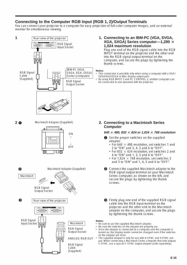
Connecting to the Computer RGB Input (RGB 1, 2)/Output TerminalsYou can connect your projector to a computer for easy projection of full-color computer images, and an externalmonitor for simultaneous viewing.
2 !
1. Connecting to an IBM-PC (VGA, SVGA,XGA, SXGA) Series computer—1,280 @1,024 maximum resolutionPlug one end of the RGB signal cable into the RGBINPUT terminal on the projector and the other endinto the RGB signal output terminal on thecomputer, and secure the plugs by tightening thethumb screws.
Notes:• This connection is possible only when using a computer with a VGA/
SVGA/XGA/SXGA or Mac display output port.• By using RGB INPUT 2 and PC CONTROL 2, another computer can
be connected to and operated with the projector.
COMPUTER RGBIN 1 IN 2
ANALOG RGB OUT
1
IBM-PC (VGA,SVGA, XGA, SXGA)Series (computer)
RGB SignalOutput Socket
Rear view of the projector
RGB SignalInput Socket
RGB SignalCable(Supplied)
2. Connecting to a Macintosh SeriesComputer640 @ 480, 832 @ 624 or 1,024 @ 768 resolution
! Set the proper switches on the suppliedadaptor.• For 640 2 480 resolution, set switches 1 and
2 to “ON” and 3, 4, 5 and 6 to “OFF”.• For 832 2 624 resolution, set switches 2 and
4 to “ON” and 1, 3, 5 and 6 to “OFF”.• For 1,024 2 768 resolution, set switches 2
and 3 to “ON” and 1, 4, 5 and 6 to “OFF”.
@ Connect the supplied Macintosh adaptor to theRGB signal output terminal on your MacintoshSeries computer, as shown on the left, andsecure the plugs by tightening the thumbscrews.
# Firmly plug one end of the supplied RGB signalcable into the RGB input terminal on theprojector and the other end to the Macintoshadaptor on the computer, and secure the plugsby tightening the thumb screws.
Notes:• Be sure to use the supplied Macintosh adaptor.• Be sure the switches on the adaptor are properly set.• Once the adaptor is connected to a computer and the computer is
turned on, the display mode cannot be changed even if the switcheson the adaptor are reset.
• The supplied adaptor is only for use with H-SYNC and V-SYNC out-put. When connecting a Macintosh Series computer that only outputsC-SYNC, use a special C-SYNC output adaptor (sold separately).
Macintosh Adaptor (Supplied)
ANALOG RGB OUT
@ Macintosh Adaptor (Supplied)
RGB SignalOutput Socket
ON↑
↓OFF
Macintosh
#
RGB SignalCable(Supplied)
ANALOG RGB OUT
Macintosh
COMPUTER RGBIN 1 IN 2
RGB SignalOutput Socket
RGB SignalInput Socket
Rear view of the projector
E-17
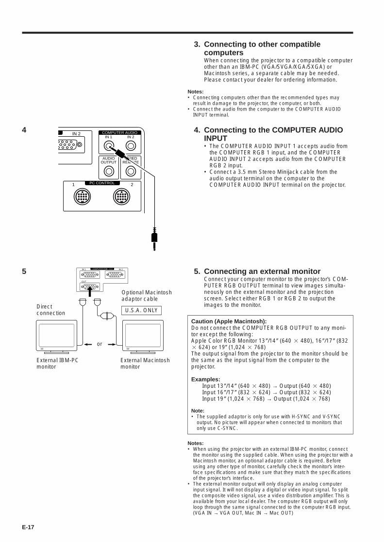
5. Connecting an external monitorConnect your computer monitor to the projector’s COM-PUTER RGB OUTPUT terminal to view images simulta-neously on the external monitor and the projectionscreen. Select either RGB 1 or RGB 2 to output theimages to the monitor.
5
3. Connecting to other compatiblecomputersWhen connecting the projector to a compatible computerother than an IBM-PC (VGA/SVGA/XGA/SXGA) orMacintosh series, a separate cable may be needed.Please contact your dealer for ordering information.
Notes:• Connecting computers other than the recommended types may
result in damage to the projector, the computer, or both.• Connect the audio from the computer to the COMPUTER AUDIO
INPUT terminal.
4. Connecting to the COMPUTER AUDIOINPUT• The COMPUTER AUDIO INPUT 1 accepts audio from
the COMPUTER RGB 1 input, and the COMPUTERAUDIO INPUT 2 accepts audio from the COMPUTERRGB 2 input.
• Connect a 3.5 mm Stereo Minijack cable from theaudio output terminal on the computer to theCOMPUTER AUDIO INPUT terminal on the projector.
4
Caution (Apple Macintosh):Do not connect the COMPUTER RGB OUTPUT to any moni-tor except the following:Apple Color RGB Monitor 13 (/14( (640 2 480), 16 (/17( (8322 624) or 19( (1,024 2 768)The output signal from the projector to the monitor should bethe same as the input signal from the computer to theprojector.
Examples:Input 13(/14( (640 2 480) → Output (640 2 480)Input 16(/17( (832 2 624) → Output (832 2 624)Input 19( (1,024 2 768) → Output (1,024 2 768)
Note:• The supplied adaptor is only for use with H-SYNC and V-SYNC
output. No picture will appear when connected to monitors thatonly use C-SYNC.
COMPUTER RGBIN 1
OUT
IN 2
Optional Macintoshadaptor cable
External Macintoshmonitor
or
U.S.A. ONLY
External IBM-PCmonitor
Directconnection
Notes:• When using the projector with an external IBM-PC monitor, connect
the monitor using the supplied cable. When using the projector with aMacintosh monitor, an optional adaptor cable is required. Beforeusing any other type of monitor, carefully check the monitor’s inter-face specifications and make sure that they match the specificationsof the projector’s interface.
• The external monitor output will only display an analog computerinput signal. It will not display a digital or video input signal. To splitthe composite video signal, use a video distribution amplifier. This isavailable from your local dealer. The computer RGB output will onlyloop through the same signal connected to the computer RGB input.(VGA IN → VGA OUT, Mac IN → Mac OUT)
COMPUTER AUDIO
PC CONTROL1 2
AUDIOOUTPUT
IN 2
WIREDREMOTE
IN 1 IN 2
E-18
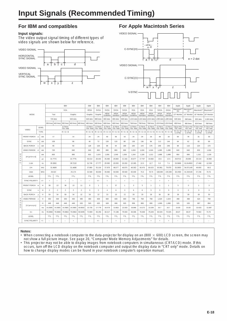
Input Signals (Recommended Timing)
For IBM and compatibles For Apple Macintosh SeriesInput signals:The video output signal timing of different types ofvideo signals are shown below for reference.
EDOM
MBI MBI MBI MBI MBI MBI MBI MBI MBI elppA elppA elppA
AGV ASEV AGVS AGVS AGVS AGVS AGX AGX AGX hsotnicaM MT
II ishsotnicaM MT
CL hsotnicaM MT
cihparGText
720 dots 640 dots 640 dots 640 dots 640 dots 832 dots800 dots 800 dots 800 dots 800 dots 1,024 dots 1,024 dots 1,024 dots
350 lines 400 lines 350 lines 400 lines 480 lines 480 lines 480 lines 480 lines 624 lines600 lines 600 lines 600 lines 600 lines 768 lines 768 lines 768 lines
cihparG cihparG ASEVenilediuG
ASEVdradnatS
ASEVdradnatS
ASEVenilediuG
ASEVdradnatS
ASEVdradnatS rotinoM"31 rotinoM"31 rotinoM"61
elppA
hsotnicaM MT
rotinoM"91
OEDIVLEVEL p-pV7.0
57 Ω daolp-pV7.0
57 Ω daolp-pV7.0
57 Ω daolp-pV7.0
57 Ω daolp-pV7.0
57 Ω daolp-pV7.0
57 Ω daolp-pV7.0
57 Ω daolp-pV7.0
57 Ω daolp-pV7.0
57 Ω daol.xamp-pV1
57 Ω daol.xamp-pV7.0
57 Ω daol.xamp-pV7.0
57 Ω daol
EPYT R • G • B R • G • B R • G • B R • G • B R • G • B R • G • B R • G • B R • G • B R • G • B R • G • BCNYS.C
R • G • BCNYS.C
R • G • BCNYS.C
HSYNC
HCROPTNORF a tod 71 41 42 42 04 65 61 42 42 61 46 87 13
CNYS b tod 801 69 04 27 821 021 08 631 631 69 46 26 56
HCROPKCAB c tod 55 05 821 821 88 46 061 061 441 671 69 611 422
DOIREPOEDIV d tod 027 046 046 008 008 008 008 420,1 420,1 420,1 046 046 238
)d+c+b+a(H1tod 009 008 238 420,1 650,1 040,1 650,1 443,1 823,1 213,1 468 698 251,1
µs 4777.13 6777.13 314.62 444.82 004.62 008.02 333.12 776.02 707.71 066.61 4175.82 595.82 421.02
tod1 sn 2803.53 9127.93 647.13 777.72 000.52 000.02 202.02 15.385 3.31 7.21 8860.33 360419.13 864.71
1 H/ zHk 9864.13 8864.13 068.73 651.53 978.73 770.84 578.64 48.363 674.65 320.06 0000.53 941179.43 396.94
tod/1 zHM 223.82 571.52 005.13 000.63 000.04 000.05 005.94 000.56 0.57 57.87 0042.03 941433.13 642.75
LEVEL TT L TT L TT L T LT T LT T LT T LT T LT T LT T LT T LT T LT T LT T LT
YTIRALOPCNYS –/+ + – + – – – –/+ + + + – – + – – –
VSYNC
HCROPTNORF w H 83 31 83 31 11 9 1 1 73 1 3 3 1 3 3 1
CNYS x H 2 2 2 2 2 3 2 4 6 3 6 6 3 3 3 3
HCROPKCAB y H 95 43 95 43 23 82 22 32 32 12 92 92 82 93 93 93
DOIREPOEDIV z H 053 004 053 004 084 084 006 006 006 006 867 867 867 084 084 426
)z+y+x+w(V1H 944 944 944 944 525 025 526 826 666 526 608 608 008 525 525 766
sm 1862.41 1862.41 1862.41 1862.41 2386.61 537.31 877.71 975.61 358.31 333.31 666.61 272.41 823.31 00.51 00.51 324.31
1 v/ zH 6680.07 6680.07 3680.07 3680.07 5049.95 908.27 052.65 713.06 881.27 000.57 600.06 960.07 920.57 76.66 76.66 205.47
LEVEL T LT T LT T LT T LT T LT T LT T LT T LT T LT T LT T LT T LT T LT T LT T LT T LT
YTIRALOPCNYS –/+ – + – + – – –/+ + + + – – +
MBI
SXGA SXGA
1,280 dots
1,024 lines
ASEVdradnatS
p-pV7.057 Ω daol
R • G • B
48
112
248
1,280 1,280
1,688
15.6
9.3
63.981
108.000
T LT
+
1
3
38
1,024
1,066
16.7
60.020
T LT
+
MBI
1,280 dots
1,024 lines
ASEVdradnatS
p-pV7.057 Ω daol
R • G • B
61
144
248
1,688
12.5
7.4
79.976
135.000
T LT
+
1
3
38
1,024
1,066
16.7
75.025
T LT
+ – – –
1,024 dots
768 lines
.xamp-pV7.057 Ω daol
R • G • BCNYS.C
35
96
173
1,024
1,328
16.650
12.538
60.0
79.76
T LT
–
3
3
30
768
804
13.387
74.70
T LT
–
Notes:• When connecting a notebook computer to the data-projector for display on an (800 2 600) LCD screen, the screen may
not show a full picture image. See page 20, “Computer Mode Memory Adjustments” for details.• This projector may not be able to display images from notebook computers in simultaneous (CRT/LCD) mode. If this
occurs, turn off the LCD display on the notebook computer and output the display data in “CRT only” mode. Details onhow to change display modes can be found in your notebook computer’s operation manual.
e
a b c d
w x y z
VIDEO SIGNAL
C-SYNC(H)
C-SYNC(V)
VIDEO SIGNAL
V-SYNC
e = 2 dot
a b c d
w x y z
VIDEO SIGNAL
HORIZONTALSYNC SIGNAL
VIDEO SIGNAL
VERTICAL SYNC SIGNAL

E-19
RGB Adjustment Controls
When displaying computer patterns which repeat every other dot (tiling, vertical stripes, etc.), interference mayoccur between the LCD pixels, causing flickering, vertical stripes, or contrast irregularities in portions of thescreen. Should this occur, use the ADJUSTMENT ß/© buttons for HORIZONTAL (LEFT/RIGHT) and VERTICAL(UP/DOWN) position adjustments to adjust for the optimum picture.
RGB Input Adjustments (“CLOCK”, “PHASE”, “V-POS”and “H-POS”)
1. Select the input of the image you want to adjust (RGB 1 or2) with the INPUT SELECT button and press the MENUbutton.With the MENU screen displayed, press the ADJUSTMENT ƒ/∂ buttonsto select “RGB 1 INPUT ADJ.” Then press the ENTER button to display the“RGB 1 INPUT ADJ.” screen.
2. Select the item you wish to adjust with the ADJUST-MENT ƒ/∂ buttons. Adjust the item with the ADJUST-MENT ß /© buttons.
Note:• To display only the item that you want to adjust, press the ENTER button after selecting the item
with the ADJUSTMENT ƒ/∂ buttons. Then adjust the item with the ADJUSTMENT ß/© buttons.
3. Press the MENU button anytime to exit RGB INPUT ADJ.
Description of Adjustment ItemsCLOCK SPEED ADJUSTMENT (FAST/SLOW)• Adjust the input signal horizontal frequency and the dot clock so that the screen
display is normal.
PHASE ADJUSTMENT (UP/DOWN)• Used to reduce image distortion or improve contrast.
HORIZONTAL POSITION ADJUSTMENT (LEFT/RIGHT)• Used to center the on-screen image by moving it to the left or right.
VERTICAL POSITION ADJUSTMENT (UP/DOWN)• Used to center the on-screen image by moving it up or down.
MODE ADJUSTMENT
CONNECTING TO IBM-PC COMPUTERS
• Ordinarily, the type of input signal is detected and the correct resolution mode(Text or Graphics) is automatically selected. However, for the following signals,set “MODE” to “ON” or “OFF” to select the projector’s resolution mode to matchthe computer display mode properly.
720 dots 2 400 lines, 720 dots 2 350 lines (Text Mode)640 dots 2 400 lines, 640 dots 2 350 lines (Graphic Mode)
• For graphic mode, select “MODE” and set the “MODE” to “ON”.• For text mode, select “MODE” again at this time, and set “MODE” to “OFF”.
CONNECTING TO MACINTOSH LC/II SERIES COMPUTERS
• When connecting to a Macintosh II with 35 kHz Dot Frequency, select “MODE”and set “MODE” to “ON”.
• When connecting to a Macintosh LC Series computer with 34.97 kHz Dot Fre-quency, set “MODE” to “OFF”.
• When connecting to third party video cards and other Macintosh computers, set“MODE” to “ON” or “OFF” to select the correct display mode.
• When the input signal is automatically detected or when there is no input signal,“MODE (---)” appears on the screen and the display mode cannot be changed.
INITIAL RESET• To return the “H-POS”, “V-POS”, “PHASE” and “CLOCK” adjustments to their
initial settings, select “RESET” and then press the ENTER button.
MEMORY SELECT• Used to store up to seven computer mode adjustments.
Note:• Avoid displaying computer patterns which repeat every other line (horizontal stripes). (Flickering
may occur, making the picture hard to see.)
2R G B 1 I N P U T A D J .
P H A S EH - P O SV - P O SM O D ER E S E TM E M O R Y S E L E C T
+00
00
: S E L .
: A D J .
: N E X TENTER
: E N DMENU
[ O F F ]
- +- +- +-
C L O C K
On-Screen Display

E-20
Computer Mode Memory Adjustments• The projector has been preset with different modes for
use with XGA and other compatible computers.However, 7 memory positions are provided to storemode adjustments.
• Each memory position can be used to store modeadjustments to match the computer.
1. Press the ENTER button to select theMemory Adjustment mode• Press the MENU button. While the MENU screen
is displayed, press the ADJUSTMENT ƒ/∂ but-tons to select “RGB1 INPUT ADJ.” Press theENTER button. The MENU mode changes asshown.
• While the RGB INPUT adjustment menu is dis-played, press the ADJUSTMENT ƒ/∂ buttons toselect “MEMORY SELECT”. Then press theENTER button to change the image.
2. Press the ADJUSTMENT ß /© buttons• The screen shown on the left will appear. There
are 7 memory positions.• Press the ADJUSTMENT ƒ button once to move
to the following screen. Press the ADJUSTMENTß/© buttons to select the number of the memoryyou want to adjust. If that memory position hasnot been set, the screen on the right will be dis-played. If it has been set, the screen on the leftwill be displayed. MEMORY No. 0 cannot be set.It contains the fixed factory preset settings.
• To make or change a setting, press the ADJUST-MENT ƒ/∂ buttons to move the cursor to “SET-TING.” Then press the ENTER button to go to theRGB INPUT adjustment menu screen. (If you donot want to make any adjustments, press theMENU button.)
• Select the item you want to adjust by pressing theADJUSTMENT ƒ/∂ buttons, then use the AD-JUSTMENT ß/© buttons to make the adjust-ments. When adjustments are completed, pressthe MENU button. The display disappears andthe adjustments are stored in memory as a usermode. See page 19 for details on the adjustmentitems.
3. Press the MENU button anytime to exitRGB INPUT ADJ.
1 When RGB 1 or 2 is selected.
2
R G B 1 A D J .R G B 1 I N P U T A D J .I M A G E A D J .A U D I OS Y S T E M S E T U PL A N G U A G E
: S E L . : N E X TENTER
: E N DMENU
R G B 1 I N P U T A D J .
P H A S EH - P O SV - P O SM O D ER E S E TM E M O R Y S E L E C T
+00
00
: S E L . : N E X TENTER
: E N DMENU
[ O F F ]
- +- +- +-
C L O C K
M E M O R Y S E L E C T
: S E L .
: A D J .
ENTER
: E N DMENU
0 1 2 3 4 5 6 7
S T A N D A R D S E T T I N G S T A N D A R D S E T T I N G
S E T T I N G
: E N T E R
M E M O R Y S E L E C T
S E T T I N G
: S E L . : B A C KENTER
: E N DMENU
0 1 2 3 4 5 6 7
M E M O R Y S E L E C T
N O N
S E T T I N G
: S E L .
: A D J .
ENTER
: E N DMENU
0 1 2 3 4 5 6 7
: E N T E R
M E M O R Y S E L E C T
: S E L .
: A D J .
ENTER
: E N DMENU
0 1 2 3 4 5 6 7
R E S O L U T I O NH O R F R E QV E R T F R E QS E T T I N G
: E N T E R
HzKHz 6 0 . 0
7 5
1 0 2 4 × 7 6 8
On-Screen Display
E-21
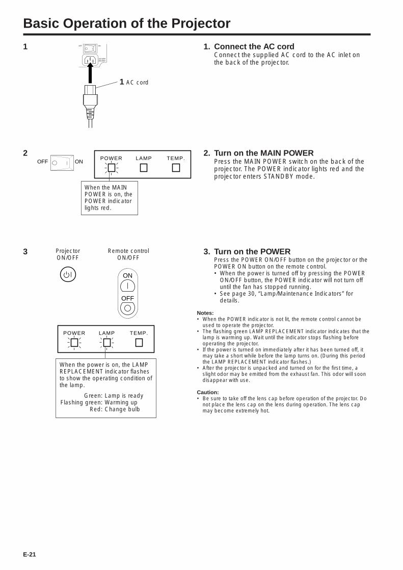
Basic Operation of the Projector
1 1. Connect the AC cordConnect the supplied AC cord to the AC inlet onthe back of the projector.
OFF ON
110-120V/200-240V~
1 AC cord
2 2. Turn on the MAIN POWERPress the MAIN POWER switch on the back of theprojector. The POWER indicator lights red and theprojector enters STANDBY mode.
ONOFFPOWER LAMP TEMP.
When the MAINPOWER is on, thePOWER indicatorlights red.
ProjectorON/OFF
Remote controlON/OFF
ON
OFF
3
POWER LAMP TEMP.
When the power is on, the LAMPREPLACEMENT indicator flashesto show the operating condition ofthe lamp.
Green: Lamp is readyFlashing green: Warming up
Red: Change bulb
3. Turn on the POWERPress the POWER ON/OFF button on the projector or thePOWER ON button on the remote control.• When the power is turned off by pressing the POWER
ON/OFF button, the POWER indicator will not turn offuntil the fan has stopped running.
• See page 30, “Lamp/Maintenance Indicators” fordetails.
Notes:• When the POWER indicator is not lit, the remote control cannot be
used to operate the projector.• The flashing green LAMP REPLACEMENT indicator indicates that the
lamp is warming up. Wait until the indicator stops flashing beforeoperating the projector.
• If the power is turned on immediately after it has been turned off, itmay take a short while before the lamp turns on. (During this periodthe LAMP REPLACEMENT indicator flashes.)
• After the projector is unpacked and turned on for the first time, aslight odor may be emitted from the exhaust fan. This odor will soondisappear with use.
Caution:• Be sure to take off the lens cap before operation of the projector. Do
not place the lens cap on the lens during operation. The lens capmay become extremely hot.
E-22
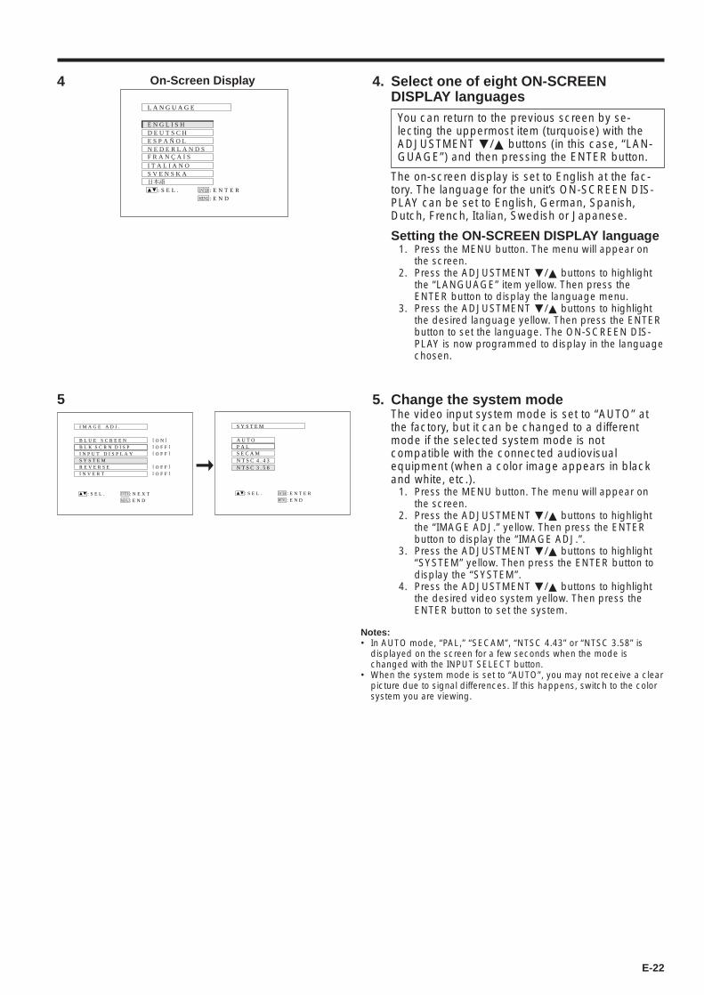
4. Select one of eight ON-SCREENDISPLAY languages
You can return to the previous screen by se-lecting the uppermost item (turquoise) with theADJUSTMENT ƒ/∂ buttons (in this case, “LAN-GUAGE”) and then pressing the ENTER button.
The on-screen display is set to English at the fac-tory. The language for the unit’s ON-SCREEN DIS-PLAY can be set to English, German, Spanish,Dutch, French, Italian, Swedish or Japanese.
Setting the ON-SCREEN DISPLAY language1. Press the MENU button. The menu will appear on
the screen.2. Press the ADJUSTMENT ƒ/∂ buttons to highlight
the “LANGUAGE” item yellow. Then press theENTER button to display the language menu.
3. Press the ADJUSTMENT ƒ/∂ buttons to highlightthe desired language yellow. Then press the ENTERbutton to set the language. The ON-SCREEN DIS-PLAY is now programmed to display in the languagechosen.
5. Change the system modeThe video input system mode is set to “AUTO” atthe factory, but it can be changed to a differentmode if the selected system mode is notcompatible with the connected audiovisualequipment (when a color image appears in blackand white, etc.).
1. Press the MENU button. The menu will appear onthe screen.
2. Press the ADJUSTMENT ƒ/∂ buttons to highlightthe “IMAGE ADJ.” yellow. Then press the ENTERbutton to display the “IMAGE ADJ.”.
3. Press the ADJUSTMENT ƒ/∂ buttons to highlight“SYSTEM” yellow. Then press the ENTER button todisplay the “SYSTEM”.
4. Press the ADJUSTMENT ƒ/∂ buttons to highlightthe desired video system yellow. Then press theENTER button to set the system.
Notes:• In AUTO mode, “PAL,” “SECAM”, “NTSC 4.43” or “NTSC 3.58” is
displayed on the screen for a few seconds when the mode ischanged with the INPUT SELECT button.
• When the system mode is set to “AUTO”, you may not receive a clearpicture due to signal differences. If this happens, switch to the colorsystem you are viewing.
L A N G U A G E
: S E L . : E N T E RENTER
: E N DMENU
N E D E R L A N D SE S P A Ñ O LD E U T S C HE N G L I S H
S V E N S K AI T A L I A N OF R A N Ç A I S
On-Screen Display4
5
: S E L . : N E X TENTER
: E N DMENU
B L U E S C R E E N
B L K S C R N D I S P
I M A G E A D J .
R E V E R S E
I N V E R T
I N P U T D I S P L A Y
[ O F F ]
[ O F F ]
[ O F F ]S Y S T E M
[ O F F ]
[ O N ] A U T O
S Y S T E M
P A LS E C A MN T S C 4 . 4 3N T S C 3 . 5 8
: S E L . : E N T E RENTER
: E N DMENU
E-23
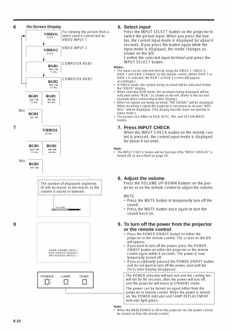
6. Select inputPress the INPUT SELECT button on the projector toswitch the picture input. When you press the but-ton, the current input mode is displayed for about 4seconds. If you press the button again while theinput mode is displayed, the mode changes asshown on the left.Confirm the selected input terminal and press theINPUT SELECT button.
Notes:• The input can be selected directly using the VIDEO 1, VIDEO 2,
DATA 1 and DATA 2 buttons on the remote control. (When DATA 1 orDATA 2 is selected, the RGB 1 or RGB 2 screen will appearaccordingly.)
• In VIDEO mode, the system being received will be indicated belowthe “VIDEO” display.
• When selecting RGB mode, the resolution being displayed will beindicated under “RGB,” as shown on the left. (Refer to the secondexample when connecting to Mac display.)
• When no signals are being received, “NO SIGNAL” will be displayed.When receiving a signal the projector is not preset to receive, “NOTREG.” will be displayed. (This display function does not operate inVideo mode.)
• The picture size differs in RGB, NTSC, PAL and SECAM INPUTmodes.
7. Press INPUT CHECKWhen the INPUT CHECK button on the remote con-trol is pressed, the current input mode is displayedfor about 4 seconds.
Note:• The INPUT CHECK button will not function if the “INPUT DISPLAY” is
turned off, as described on page 28.
8. Adjust the volumePress the VOLUME UP-DOWN buttons on the pro-jector or on the remote control to adjust the volume.
MUTE• Press the MUTE button to temporarily turn off the
sound.• Press the MUTE button once again to turn the
sound back on.
9. To turn off the power from the projectoror the remote control• Press the POWER ON/OFF button on either the
projector or the remote control. The screen on the leftwill appear.
• If you want to turn off the power, press the POWERON/OFF button on either the projector or the remotecontrol again within 4 seconds. The power is nowtemporarily turned off.
• If you accidentally pressed the POWER ON/OFF buttonand do not want to turn off the power, wait until theOn-Screen Display disappears.
The POWER indicator will turn red and the cooling fanwill run for 90 seconds, then the power will turn off,and the projector will return to STANDBY mode.The power can be turned on again either from theprojector or remote control. When the power is turnedon, the POWER indicator and LAMP REPLACEMENTindicator light green.
Note:• When the MAIN POWER is off on the projector set, the power cannot
be turned on from the remote control.
For viewing the picture from avideo source connected to:VIDEO INPUT 1
COMPUTER RGB2
COMPUTER RGB1
VIDEO INPUT 2
Mac
On-Screen Display6
7
9
POWER LAMP TEMP.
V O L U M E3 8
The number of displayed segments(0–60) increases or decreases as thevolume is raised or lowered.
T U R N P O W E R O F F ?
Y E S : P R E S S
N O : P L E A S E W A I T
A G A I N
Mac
E-24
Adjusting the Picture
• This projector’s picture is factory preset to standardsettings. However, you can adjust it to suit your ownpreferences with the ADJUSTMENT buttons on theprojector and the remote control.
• The adjustments can be memorized in RGB 1, RGB 2,VIDEO 1 or VIDEO 2 separately.
• Four picture modes can be adjusted: “PICTURE,”“BRIGHT,” “RED,” and “BLUE”.
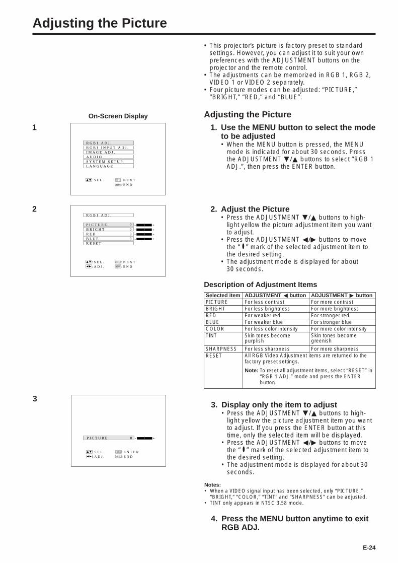
Adjusting the Picture1. Use the MENU button to select the mode
to be adjusted• When the MENU button is pressed, the MENU
mode is indicated for about 30 seconds. Pressthe ADJUSTMENT ƒ/∂ buttons to select “RGB 1ADJ.”, then press the ENTER button.
2. Adjust the Picture• Press the ADJUSTMENT ƒ/∂ buttons to high-
light yellow the picture adjustment item you wantto adjust.
• Press the ADJUSTMENT ß/© buttons to movethe “ ” mark of the selected adjustment item tothe desired setting.
• The adjustment mode is displayed for about30 seconds.
Description of Adjustment ItemsADJUSTMENT ß buttonFor less contrastFor less brightnessFor weaker redFor weaker blueFor less color intensity
For less sharpness
Selected itemPICTUREBRIGHTREDBLUECOLORTINT
SHARPNESSRESET
ADJUSTMENT © buttonFor more contrastFor more brightnessFor stronger redFor stronger blueFor more color intensity
For more sharpness
1
R G B 1 A D J .R G B 1 I N P U T A D J .I M A G E A D J .A U D I OS Y S T E M S E T U PL A N G U A G E
: S E L . : N E X TENTER
: E N DMENU
On-Screen Display
R G B 1 A D J .
B R I G H TR E DB L U ER E S E T
+00
00
: S E L .
: A D J .
: N E X TENTER
: E N DMENU
- +- +- +-
P I C T U R E
2
All RGB Video Adjustment items are returned to thefactory preset settings.
Note: To reset all adjustment items, select “RESET” in“RGB 1 ADJ.” mode and press the ENTERbutton.
3. Display only the item to adjust• Press the ADJUSTMENT ƒ/∂ buttons to high-
light yellow the picture adjustment item you wantto adjust. If you press the ENTER button at thistime, only the selected item will be displayed.
• Press the ADJUSTMENT ß/© buttons to movethe “ ” mark of the selected adjustment item tothe desired setting.
• The adjustment mode is displayed for about 30seconds.
Notes:• When a VIDEO signal input has been selected, only “PICTURE,”
“BRIGHT,” “COLOR,” “TINT” and “SHARPNESS” can be adjusted.• TINT only appears in NTSC 3.58 mode.
4. Press the MENU button anytime to exitRGB ADJ.
+
: S E L .
: A D J .
: E N T E RENTER
: E N DMENU
-P I C T U R E 0
3
Skin tones becomepurplish
Skin tones becomegreenish
E-25
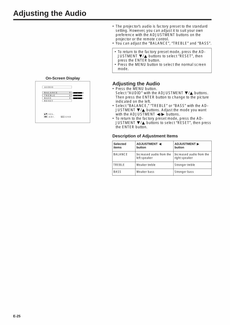
• The projector’s audio is factory preset to the standardsetting. However, you can adjust it to suit your ownpreference with the ADJUSTMENT buttons on theprojector or the remote control.
• You can adjust the “BALANCE”, “TREBLE” and “BASS”.
Adjusting the Audio
• To return to the factory preset mode, press the AD-JUSTMENT ƒ/∂ buttons to select “RESET”, thenpress the ENTER button.
• Press the MENU button to select the normal screenmode.
Adjusting the Audio• Press the MENU button.
Select “AUDIO” with the ADJUSTMENT ƒ/∂ buttons.Then press the ENTER button to change to the pictureindicated on the left.
• Select “BALANCE,” “TREBLE” or “BASS” with the AD-JUSTMENT ƒ/∂ buttons. Adjust the mode you wantwith the ADJUSTMENT ß/© buttons.
• To return to the factory preset mode, press the AD-JUSTMENT ƒ/∂ buttons to select “RESET”, then pressthe ENTER button.
Description of Adjustment Items
ADJUSTMENT ßbutton
Increased audio from theleft speaker
Weaker treble
Weaker bass
ADJUSTMENT ©button
Increased audio from theright speaker
Stronger treble
Stronger bass
Selecteditems
BALANCE
TREBLE
BASS
A U D I O
T R E B L EB A S SR E S E T
00
0
: S E L .
: A D J . : E N DMENU
RL
+- +-
B A L A N C E
On-Screen Display
E-26
Functions on the Projector
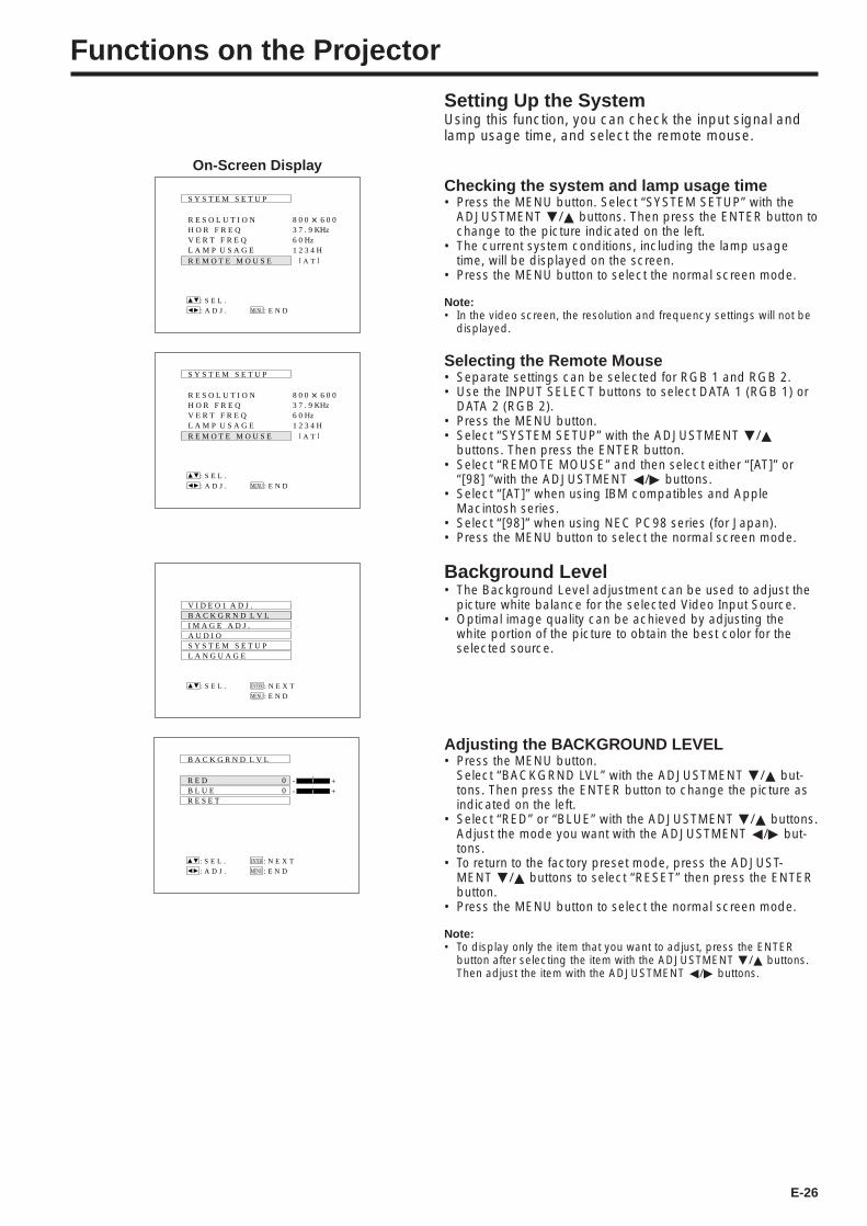
Setting Up the SystemUsing this function, you can check the input signal andlamp usage time, and select the remote mouse.
Checking the system and lamp usage time• Press the MENU button. Select “SYSTEM SETUP” with the
ADJUSTMENT ƒ/∂ buttons. Then press the ENTER button tochange to the picture indicated on the left.
• The current system conditions, including the lamp usagetime, will be displayed on the screen.
• Press the MENU button to select the normal screen mode.
Note:• In the video screen, the resolution and frequency settings will not be
displayed.
Selecting the Remote Mouse• Separate settings can be selected for RGB 1 and RGB 2.• Use the INPUT SELECT buttons to select DATA 1 (RGB 1) or
DATA 2 (RGB 2).• Press the MENU button.• Select “SYSTEM SETUP” with the ADJUSTMENT ƒ/∂
buttons. Then press the ENTER button.• Select “REMOTE MOUSE” and then select either “[AT]” or
“[98] ”with the ADJUSTMENT ß/© buttons.• Select “[AT]” when using IBM compatibles and Apple
Macintosh series.• Select “[98]” when using NEC PC98 series (for Japan).• Press the MENU button to select the normal screen mode.
Background Level• The Background Level adjustment can be used to adjust the
picture white balance for the selected Video Input Source.• Optimal image quality can be achieved by adjusting the
white portion of the picture to obtain the best color for theselected source.
Adjusting the BACKGROUND LEVEL• Press the MENU button.
Select “BACKGRND LVL” with the ADJUSTMENT ƒ/∂ but-tons. Then press the ENTER button to change the picture asindicated on the left.
• Select “RED” or “BLUE” with the ADJUSTMENT ƒ/∂ buttons.Adjust the mode you want with the ADJUSTMENT ß/© but-tons.
• To return to the factory preset mode, press the ADJUST-MENT ƒ/∂ buttons to select “RESET” then press the ENTERbutton.
• Press the MENU button to select the normal screen mode.
Note:• To display only the item that you want to adjust, press the ENTER
button after selecting the item with the ADJUSTMENT ƒ/∂ buttons.Then adjust the item with the ADJUSTMENT ß/© buttons.
On-Screen Display
S Y S T E M S E T U P
R E S O L U T I O NH O R F R E QV E R T F R E Q
R E M O T E M O U S E
: S E L .
: E N DMENU
8 0 0 @ 6 0 0
[ A T ]
: A D J .
6 0 HzL A M P U S A G E 1 2 3 4 H
3 7 . 9 KHz
V I D E O 1 A D J .B A C K G R N D L V LI M A G E A D J .A U D I OS Y S T E M S E T U PL A N G U A G E
: S E L . : N E X TENTER
: E N DMENU
B A C K G R N D L V L
R E DB L U ER E S E T
+00
: S E L .
: A D J .
: N E X TENTER
: E N DMENU
- +-
S Y S T E M S E T U P
R E S O L U T I O NH O R F R E QV E R T F R E Q
R E M O T E M O U S E
: S E L .
: E N DMENU
8 0 0 @ 6 0 0
[ A T ]
: A D J .
6 0 HzL A M P U S A G E 1 2 3 4 H
3 7 . 9 KHz
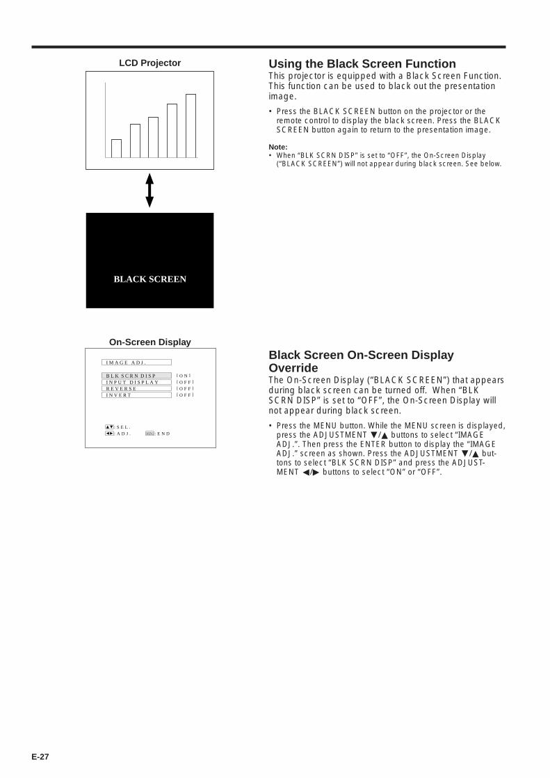
E-27
Using the Black Screen FunctionThis projector is equipped with a Black Screen Function.This function can be used to black out the presentationimage.
• Press the BLACK SCREEN button on the projector or theremote control to display the black screen. Press the BLACKSCREEN button again to return to the presentation image.
Note:• When “BLK SCRN DISP” is set to “OFF”, the On-Screen Display
(“BLACK SCREEN”) will not appear during black screen. See below.
LCD Projector
Black Screen On-Screen DisplayOverrideThe On-Screen Display (“BLACK SCREEN”) that appearsduring black screen can be turned off. When “BLKSCRN DISP” is set to “OFF”, the On-Screen Display willnot appear during black screen.
• Press the MENU button. While the MENU screen is displayed,press the ADJUSTMENT ƒ/∂ buttons to select “IMAGEADJ.”. Then press the ENTER button to display the “IMAGEADJ.” screen as shown. Press the ADJUSTMENT ƒ/∂ but-tons to select “BLK SCRN DISP” and press the ADJUST-MENT ß/© buttons to select “ON” or “OFF”.
B L K S C R N D I S P
I M A G E A D J .
R E V E R S EI N V E R T
I N P U T D I S P L A Y
: S E L .
: A D J . : E N DMENU
[ O F F ]
[ O F F ]
[ O F F ]
[ O N ]
On-Screen Display
BLACK SCREEN
E-28
Using the Blue Screen FunctionThis projector is equipped with a Blue Screen functionthat will turn the screen blue when the video input termi-nal is not connected to anything, or the video componentis turned off.
• Press the MENU button. While the MENU screen is displayed,press the ADJUSTMENT ƒ/∂ buttons to select “IMAGEADJ.”. Then press the ENTER button to display the “IMAGEADJ.” screen as shown. Press the ADJUSTMENT ƒ/∂ but-tons to select “BLUE SCREEN,” and press the ADJUST-MENT ß/© buttons to select “ON” or “OFF”. Press the MENUbutton to return to the normal screen.
• When the Blue Screen function is on, the screen will turn bluewhen no video signal is being input through the video inputterminal.
• When the Blue Screen function is on, and no video signal isinput via the input terminal for more than 15 minutes, thepower is automatically turned off.
• The indicators appear as shown each minute before thepower is turned off, from 5 minutes before until 1 minutebefore.
Notes:• The Blue Screen function does not operate in RGB mode.• When the power is turned off, the POWER indicator will light red.• To turn the power on again, press the POWER button to set it to OFF,
then press it again to set it to ON.
On-Screen Display
Using the Input Mode On-Screen DisplayOverride FunctionThe On-Screen Displays that appear during input select(“RGB 1,024 2 768, 75 Hz,” etc.) can be turned off.Once “INPUT DISPLAY” is turned off, the On-Screen Dis-plays will not appear even if the INPUT CHECK button onthe remote control is pressed.
• Press the MENU button. While the MENU screen is displayed,press the ADJUSTMENT ƒ/∂ buttons to select “IMAGEADJ.”. Then press the ENTER button to display the “IMAGEADJ.” screen as shown. Press the ADJUSTMENT ƒ/∂ but-tons to select “INPUT DISPLAY,” and press ADJUST-MENT ß/© buttons to select “ON” or “OFF”.
• When OFF is selected, the On-Screen Display (“RGB1,024 2 768, 75 Hz,” etc.) will not be displayed during inputselect.
B L U E S C R E E N
B L K S C R N D I S P
I M A G E A D J .
R E V E R S E
I N V E R T
I N P U T D I S P L A Y
[ O F F ]
[ O F F ]
[ O F F ]S Y S T E M
[ O F F ]
[ O N ]
: S E L .
: A D J . : E N DMENU
REMAIN 5M
REMAIN 4M
REMAIN 1M
B L K S C R N D I S P
I M A G E A D J .
R E V E R S EI N V E R T
I N P U T D I S P L A Y
: S E L .
: A D J . : E N DMENU
[ O F F ]
[ O F F ]
[ O F F ]
[ O F F ]
E-29
Air Filter Maintenance
• The air filter should be cleaned every 100 hours of use. Clean the filter moreoften when the projector is used in a dusty or smoky location.
• Have your nearest Authorized Sharp Industrial LCD Products Dealer or Ser-vice Center exchange the filter (PFILD0080CEZZ) when it is no longer pos-sible to clean it.
Cleaning and Replacing the Filter
4 6Insert the tab on the end of thefilter cover into the filter coveropening and press the filtercover into position.
Place the filter underneath thetabs on the filter frame.Return the air filter to its originalposition in the filter coveropening.
Clean the dust off the air filterand cover with a vacuumcleaner extension hose.
Clean the AIR FILTER. 5 Replace the AIR FILTER. Replacethe FILTER COVER.
1 3Turn OFFthe MAIN POWER. 2 Remove
the FILTER COVER.Removethe AIR FILTER.
Grasp the air filter between yourfingers and lift it out of the filtercover.
Press the tab in the direction ofthe arrow and lift open the filtercover.
Tab
Open
POWER indicator goes off.Unplug the power cord.
AIR FILTER cover
Note:• Be sure the AIR FILTER COVER is securely installed. The power cannot be turned on unless it is correctly installed.
Press
ONOFF
Bottom Air Filter

E-30
Lamp/Maintenance Indicators
LampThe lamp operating life differs, depending on the usage environment. It is recommended that the lamp bereplaced after 4,000 cumulative hours of use.• When the lamp is nearing the end of its operating life, the picture and color quality will deteriorate. At this point, replace the
lamp. (See pages 31 and 32.)
Check• The projector AC cord is not plugged into the AC wall outlet.• The main power switch is not pressed.• The input is wrong. (See pages 22 and 23.)• Cables improperly connected to rear panel of the projector. (See pages 14, 15, 16 and 17.)• Remote control batteries have run down. (See page 7.)• The optional cable for the remote control is improperly inserted.• The main power of the remote control is not turned on.• The remote control’s MOUSE/ADJUSTMENT switch is set to MOUSE.• Cables improperly connected to rear panel of the projector. (See pages 14, 15, 16 and 17.)• The PICTURE and BRIGHT adjustments are set to minimum position. (See page 24.)• On-Screen Display (“BLACK SCREEN”) is turned off and Black Screen function is turned on, creating a
black image. (See page 27.)• The COLOR and TINT adjustments are not correct. (See page 24.)• Adjust the focus. (See page 9.)• The projection distance is too long or too short to allow for proper focus. (See page 10.)• Cables improperly connected to rear panel of the projector. (See pages 14, 15, 16 and 17.)• Volume is set to minimum. (See page 23.)• If the picture is normal, the sound is due to cabinet shrinkage caused by temperature changes. This
will not affect operation or performance.• Refer to “Lamp/Maintenance Indicators” on page 30.
ProblemNo picture and no sound.
Sound is heard but no pictureappears.
Color is faded or poor.Picture is blurred.
Picture appears but no sound isheard.An unusual sound is occasionallyheard from the cabinet.Maintenance indicator lights up.
Notes:• If the TEMPERATURE indicator comes on, follow the above possible solutions and then wait until the projector has cooled down completely
before turning the power back on. (At least 5 minutes.)• When the power is turned off and then turned on again, as during a brief rest, the LAMP REPLACEMENT indicator may be triggered, pre-
venting the power from going on. When this happens, take the power plug out of the AC outlet and put it back in again.
Before Calling for Service
Problem
• Blocked air intake.
• Clogged air filter.
• Cooling fan breakdown.• Internal circuit failure.
• Burnt-out lamp.
• Lamp circuit failure.
Warning Indicator
The internaltemperature isabnormally high.
TEMPERATUREindicator
LAMP REPLACE-MENT indicator
The lamp does notlight up.
Symptom Possible Solution
• Relocate projector to a proper location.
• Clean the filter.(See page 29.)
• Take the projector to your nearest Autho-rized Sharp Industrial LCD Products Dealeror Service Center for repair.
• Carefully replace the lamp.• Take the projector to your nearest Autho-
rized Sharp Industrial LCD Products Dealeror Service Center for repair.
• The warning lights on the projector indicate problems inside theprojector.
• There are two warning lights: a TEMPERATURE indicator which warnsthat the projector is too hot, and a LAMP REPLACEMENT indicator whichlets you know when to change the lamp.
• If a problem occurs, either the TEMPERATURE indicator or the LAMPREPLACEMENT indicator will light up red, and the power will shut off.After turning off the power, follow the procedures given below.
POWER LAMP TEMP.
LAMP REPLACEMENTindicator
TEMPERATUREindicator
Maintenance Indicators
Note: The lamp usage time can be checked with the On-Screen display. (See page 26.)
• If the new lamp does not light after replacement, take your projector to the nearest Authorized Sharp Industrial LCD ProductsDealer or Service Center for repair.
• Intense light hazard. Do not attempt to look into the aperture and lens while the projector is operating.

E-31
Lamp Replacement
The lamp in the projector has a finite service life. The lamp operating life differs, depending on the usageenvironment. It is recommended that the lamp be replaced after 4,000 cumulative hours of use. The lamp usagetime can be checked at the On-Screen display. (See page 26.)
• Replace the lamp when the picture starts becoming dark and the color contrast deteriorates.
Purchase a replacement UHP lamp unit (lamp/cage module) of the current type BQC-XGNV2U//1 from yournearest Authorized Sharp Industrial LCD Products Dealer. Then change the lamp by carefully following theinstructions below.If you wish, you may bring the projector to your nearest Authorized Sharp Industrial LCD Products Dealer.
IMPORTANT NOTE TO U.S. CUSTOMERS:The lamp included with this projector is backed by a 90-day parts and labor limited warranty. All service of thisprojector under warranty, including lamp replacement, must be obtained through an Authorized Sharp IndustrialLCD Products Dealer or Service Center. For the name of the nearest Authorized Sharp Industrial LCD ProductsDealer or Service Center, please call toll-free: 1-800-BE-SHARP (1-800-237-4277).
How to Change the LampPrecaution:• Take care not to touch either the glass surface of the lamp
cage or the inside of the projector with your bare hands.
Removing the lamp unit (see figure)1. Press the power button (a) and turn the instrument off. After the cooling fan stops, turn off the MAIN POWER
switch (b). Remove the power cord from the AC outlet.2. The lamp may be extremely hot. Wait at least an hour after the power cord is disconnected before carrying
out the following procedures.3. Turn over the projector and unfasten the user service screw (d) that secures the lamp cage cover (c) as
shown in the above diagram. Then remove the lamp cage cover by pulling it in the direction of the arrow.
4. After the lamp cage (i) has sufficiently cooled, remove securing screws (e), (f) and (g) from the lamp cage.5. Hold the lamp cage (i) by the handle (h) and pull it towards you.
(i)
(k)(f)
(e)(g)(h)
(j)
(a)
U.S.A. ONLY
(c)
(d)
(b)
Note:• When the lamp cage cover (c) has been removed, check that the surface of the lamp cage (i) has fully cooled before pro-
ceeding with step 4.
E-32
Caution:• Because some parts may not be sufficiently cooled, be sure to remove the lamp cage by the handle while taking care not
to touch the metallic areas.
Installing the lamp unit1. Hold the lamp cage (i) by the handle (h) and press it in firmly while making sure that grooves on the side of
the lamp cage (j) are properly aligned with the projections inside the lamp cage compartment, and that theholes on the top of the lamp cage (k) are aligned with the screw holes on the projector.
2. Tighten screws (e), (f), (g) and (d), then perform the above instructions in the reverse order.
1. Plug in the power cord.
2. While pressing the ADJUSTMENT ©, ADJUST-MENT ƒ, and ENTER buttons on the projector, turnon the MAIN POWER switch.
After the projector turns on, “LAMP 0000H” is displayed,indicating that the lamp timer is reset.
Note:• Only reset the lamp timer after replacing the lamp.
Resetting the lamp timer
1OFF ON
110-120V/200-240V~
2
3
ONOFF
LAMP
0000H
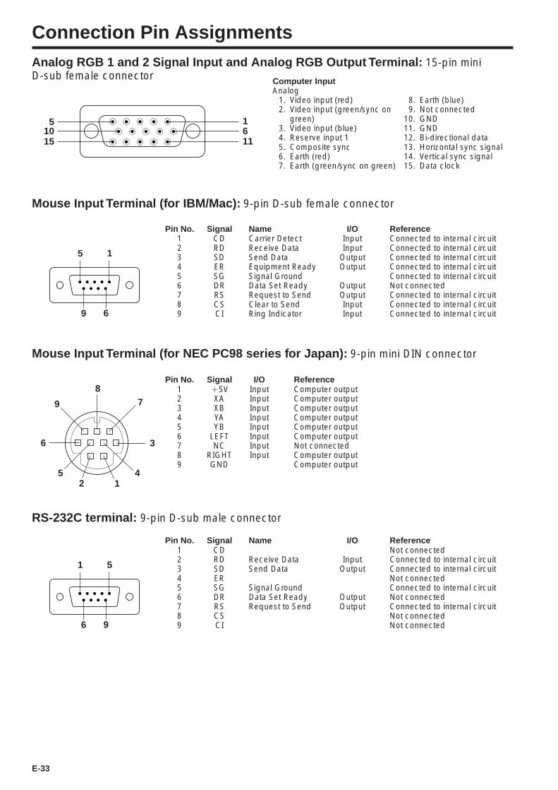
E-33
Connection Pin AssignmentsAnalog RGB 1 and 2 Signal Input and Analog RGB Output Terminal: 15-pin miniD-sub female connector Computer Input
Analog1. Video input (red)2. Video input (green/sync on
green)3. Video input (blue)4. Reserve input 15. Composite sync6. Earth (red)7. Earth (green/sync on green)
1
15
5611
10
8. Earth (blue)9. Not connected
10. GND11. GND12. Bi-directional data13. Horizontal sync signal14. Vertical sync signal15. Data clock
5 1
9 6
Pin No. Signal Name I/O Reference1 CD Carrier Detect Input Connected to internal circuit2 RD Receive Data Input Connected to internal circuit3 SD Send Data Output Connected to internal circuit4 ER Equipment Ready Output Connected to internal circuit5 SG Signal Ground Connected to internal circuit6 DR Data Set Ready Output Not connected7 RS Request to Send Output Connected to internal circuit8 CS Clear to Send Input Connected to internal circuit9 CI Ring Indicator Input Connected to internal circuit
Mouse Input Terminal (for IBM/Mac): 9-pin D-sub female connector
Pin No. Signal I/O Reference1 `5V Input Computer output2 XA Input Computer output3 XB Input Computer output4 YA Input Computer output5 YB Input Computer output6 LEFT Input Computer output7 NC Input Not connected8 RIGHT Input Computer output9 GND Computer output
6
8
9 7
52 1
4
Mouse Input Terminal (for NEC PC98 series for Japan): 9-pin mini DIN connector
1 5
6 9
Pin No. Signal Name I/O Reference1 CD Not connected2 RD Receive Data Input Connected to internal circuit3 SD Send Data Output Connected to internal circuit4 ER Not connected5 SG Signal Ground Connected to internal circuit6 DR Data Set Ready Output Not connected7 RS Request to Send Output Connected to internal circuit8 CS Not connected9 CI Not connected
RS-232C terminal: 9-pin D-sub male connector
3
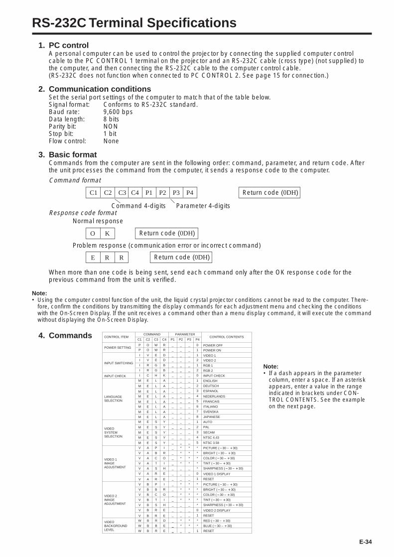
E-34
RS-232C Terminal Specifications
1. PC controlA personal computer can be used to control the projector by connecting the supplied computer controlcable to the PC CONTROL 1 terminal on the projector and an RS-232C cable (cross type) (not supplied) tothe computer, and then connecting the RS-232C cable to the computer control cable.(RS-232C does not function when connected to PC CONTROL 2. See page 15 for connection.)
2. Communication conditionsSet the serial port settings of the computer to match that of the table below.Signal format: Conforms to RS-232C standard.Baud rate: 9,600 bpsData length: 8 bitsParity bit: NONStop bit: 1 bitFlow control: None
3. Basic formatCommands from the computer are sent in the following order: command, parameter, and return code. Afterthe unit processes the command from the computer, it sends a response code to the computer.
Return code (0DH)C1 C2 C3 C4 P1 P2 P3 P4
Response code formatNormal response
O K Return code (0DH)
Problem response (communication error or incorrect command)
E R R Return code (0DH)
Command 4-digits Parameter 4-digits
When more than one code is being sent, send each command only after the OK response code for theprevious command from the unit is verified.
Note:• Using the computer control function of the unit, the liquid crystal projector conditions cannot be read to the computer. There-
fore, confirm the conditions by transmitting the display commands for each adjustment menu and checking the conditionswith the On-Screen Display. If the unit receives a command other than a menu display command, it will execute the commandwithout displaying the On-Screen Display.
Note:• If a dash appears in the parameter
column, enter a space. If an asteriskappears, enter a value in the rangeindicated in brackets under CON-TROL CONTENTS. See the exampleon the next page.
Command format
4. Commands CONTROL ITEMCOMMAND PARAMETER
CONTROL CONTENTSC1 C2 C3 C4 P1 P2 P3 P4
INPUT SWITCHING
POWER SETTING
INPUT CHECK
_ _ _ VIDEO 2
_ _ _ VIDEO 1
_ _ _ POWER ON
_ _ _ POWER OFF
RGB 1
RGB 2
INPUT CHECK
ENGLISH
DEUTSCH
ESPANOL
NEDERLANDS
FRANCAIS
ITALIANO
SVENSKA
JAPANESE
AUTO
PAL
SECAM
NTSC 4.43
PICTURE (!30 – ~30)
BRIGHT (!30 – ~30)
COLOR (!30 – ~30)
TINT (!30 – ~30)
SHARPNESS (!30 – ~30)
VIDEO 1 DISPLAY
RESET
_ _ _
LANGUAGESELECTION
_ _ _
_ _ _
_ _ _
_ _ _
_ _ _
_ _ _
_ _ _
_ _ _
VIDEOSYSTEMSELECTION
VIDEO 1IMAGEADJUSTMENT
_ _ _
_ _ _
_ _ _
_ _ _
_ * *
_ * *
_ * *
_ * *
_ _ _
_ _ _
_ _ _
_ _ _
I
I
P
P
I
M
M
M
M
M
M
M
M
M
M
M
M
V
V
V
V
V
V
V
I
I
V
V
O
O
R
E
E
E
E
E
E
E
E
E
E
E
E
A
A
A
A
A
A
A
R
C
E
E
W
W
G
L
L
L
L
L
L
L
L
S
S
S
S
P
B
C
T
S
R
R
G
H
D
D
R
R
B
A
A
A
A
A
A
A
A
Y
Y
Y
Y
I
R
O
I
H
E
E
B
K _ _ _
2
1
1
0
1
1
2
3
4
5
6
7
8
1
2
3
4
NTSC 3.58_ _ _M E S Y 5
*
*
*
*
*
0
1
PICTURE (!30 – ~30)
BRIGHT (!30 – ~30)
COLOR (!30 – ~30)
TINT (!30 – ~30)
SHARPNESS (!30 – ~30)
VIDEO 2 DISPLAY
RESET
VIDEO 2IMAGEADJUSTMENT
VIDEOBACKGROUNDLEVEL
_ * *
_ * *
_ * *
_ * *
_ _ _
_ _ _
_ _ _
_
_ _ _
V
V
V
V
V
V
V
B
B
B
B
B
B
B
P
B
C
T
S
R
R
I
R
O
I
H
E
E
*
*
*
*
*
0
1
2
0
RED (!30 – ~30)
BLUE (!30 – ~30)
RESET
_ * *
_
_
W
W
W
B
B
B
R
B
R
D
E
E
*
*
1
* *
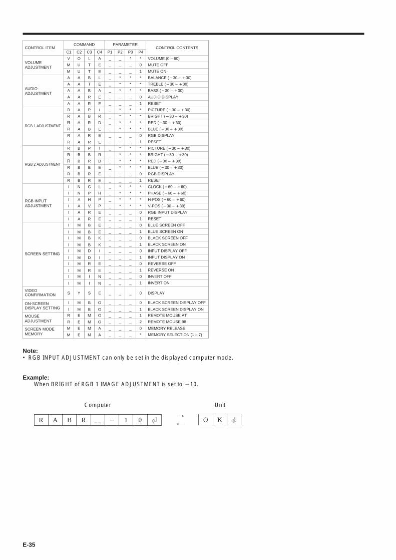
E-35
→←
Unit
CONTROL ITEMCOMMAND PARAMETER
CONTROL CONTENTS1C 2C 3C 4C 1P 2P 3P 4P
VOLUMEADJUSTMENT
_ _ * VOLUME (0 – 60)
_ _ _ MUTE OFF
_ _ _ MUTE ON
AUDIOADJUSTMENT
_ * * BALANCE (!30 – ~30)
_ * * TREBLE (!30 – ~30)
_ * * BASS (!30 – ~30)
_ _ _ AUDIO DISPLAY
_ _ _ RESET
RGB 2 ADJUSTMENT
_ * * PICTURE (!30 – ~30)
_ * * BRIGHT (!30 – ~30)
_ * * RED (!30 – ~30)
_ * * BLUE (!30 – ~30)
_ _ _ RGB DISPLAY
_ _ _ RESET
RGB INPUTADJUSTMENT
_ * * CLOCK (!60 – ~60)
_ * * PHASE (!60 – ~60)
_ * * H-POS (!60 – ~60)
_ * * V-POS (!30 – ~30)
_ _ _ RGB INPUT DISPLAY
_ _ _ RESET
SCREEN SETTING
_ _ _ BLUE SCREEN OFF
_ _ _ BLUE SCREEN ON
_ _ _ BLACK SCREEN OFF
_ _ _ BLACK SCREEN ON
_ _ _ INPUT DISPLAY OFF
_ _ _ INPUT DISPLAY ON
_ _ _ REVERSE OFF
_ _ _ REVERSE ON
_ _ _ INVERT OFF
_ _ _ INVERT ON
ON-SCREENDISPLAY SETTING
_ _ _ BLACK SCREEN DISPLAY OFF
_ _ _ BLACK SCREEN DISPLAY ON
MOUSEADJUSTMENT
_ _ _ REMOTE MOUSE AT
_ _ _ REMOTE MOUSE 98
RGB 1 ADJUSTMENT
_ * * PICTURE (!30 – ~30)
_ * * BRIGHT (!30 – ~30)
_ * * RED (!30 – ~30)
_ * * BLUE (!30 – ~30)
_ _ _ RGB DISPLAY
_ _ _ RESET
SCREEN MODEMEMORY
V
M
M
A
A
A
A
R
R
R
R
R
I
I
I
I
I
I
I
I
I
I
I
I
I
I
I
I
I
R
R
R
R
R
R
A
R
I
R
M
O
U
U
A
A
A
A
B
B
B
B
B
N
N
A
A
A
M
M
M
M
M
M
M
M
M
M
M
M
E
A
A
A
A
A
A
B
A
A
E
L
T
T
B
T
B
R
P
B
R
B
R
C
P
H
V
R
B
B
D
R
I
B
B
D
R
I
B
B
M
P
B
R
B
R
R
R
R
R
M
A
E
E
L
E
A
E
I
R
D
E
E
L
H
P
P
E
E
K
I
E
N
E
K
I
E
N
O
O
O
I
R
D
E
E
E
E
E
E
A
R
M
E
E
M
M
O
A
_ _ _ MEMORY RELEASE
_ _ _
*
0
1
*
*
*
0
1
*
*
*
*
0
1
*
*
*
*
0
1
0
1
0
1
0
1
0
1
0
1
0
1
VIDEOCONFIRMATION _ _ _ DISPLAYS Y S E 0
1
2
*
*
*
*
0
1
0
* MEMORY SELECTION (1 – 7)
Note:• RGB INPUT ADJUSTMENT can only be set in the displayed computer mode.
Example:When BRIGHT of RGB 1 IMAGE ADJUSTMENT is set to 110.
Computer
R A B R 1 0__ 1 O K
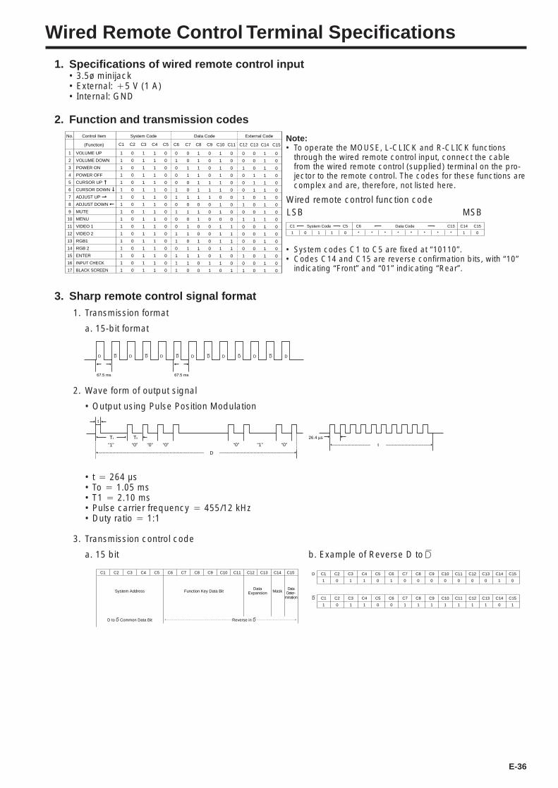
E-36
Wired Remote Control Terminal Specifications
1. Specifications of wired remote control input• 3.5ø minijack• External: `5 V (1 A)• Internal: GND
2. Function and transmission codes
Wired remote control function code
1 0 1 1 0 * * * * * * * * 1 0
C1 System Code C5 C6 Data Code C13 C14 C15
LSB MSB
• System codes C1 to C5 are fixed at “10110”.• Codes C14 and C15 are reverse confirmation bits, with “10”
indicating “Front” and “01” indicating “Rear”.
Note:• To operate the MOUSE, L-CLICK and R-CLICK functions
through the wired remote control input, connect the cablefrom the wired remote control (supplied) terminal on the pro-jector to the remote control. The codes for these functions arecomplex and are, therefore, not listed here.
3. Sharp remote control signal format1. Transmission format
a. 15-bit format
2. Wave form of output signal
• Output using Pulse Position Modulation
D D D D D D D D D D D DD
67.5 ms 67.5 ms
“0”“1”“0”
D
“0”“0”“0”“1”
T0T1
t
• t 4 264 µs• To 4 1.05 ms• T1 4 2.10 ms• Pulse carrier frequency 4 455/12 kHz• Duty ratio 4 1:1
3. Transmission control code
a. 15 bit b. Example of Reverse D to
C1
1
D C2
0
C3
1
C4
1
C5
0
C6
1
C7
0
C8
0
C9
0
C10
0
C11
0
C12
0
C13
0
C14
1
C15
0
C1
1
D C2
0
C3
1
C4
1
C5
0
C6
0
C7
1
C8
1
C9
1
C10
1
C11
1
C12
1
C13
1
C14
0
C15
1
C1 C2 C3 C4 C5 C6 C7 C8 C9 C10 C11 C12 C13 C14
System Address
D to D Common Data Bit Reverse in D
Function Key Data BitData
ExpansionData
Deter-mination
Mask
C15
VOLUME UP
VOLUME DOWN
POWER ON
POWER OFF
CURSOR UP
CURSOR DOWN
ADJUST UP
ADJUST DOWN
MUTE
MENU
VIDEO 1
VIDEO 2
RGB1
RGB 2
ENTER
INPUT CHECK
BLACK SCREEN
1
2
3
4
5
6
7
8
9
10
11
12
13
14
15
16
17
1
1
1
1
1
1
1
1
1
1
1
1
1
1
1
1
1
C1
0
0
0
0
0
0
0
0
0
0
0
0
0
0
0
0
0
C2
1
1
1
1
1
1
1
1
1
1
1
1
1
1
1
1
1
C3
1
1
1
1
1
1
1
1
1
1
1
1
1
1
1
1
1
C4
0
0
0
0
0
0
0
0
0
0
0
0
0
0
0
0
0
C5
0
1
0
0
0
1
1
0
1
0
0
1
1
0
1
1
1
C6
0
0
1
1
0
0
1
0
1
0
1
1
0
1
1
1
0
C7
1
1
1
1
1
1
1
0
1
1
0
0
1
1
1
0
0
C8
0
0
0
0
1
1
1
0
0
0
0
0
0
0
0
1
1
C9
1
1
1
1
1
1
0
1
1
0
1
1
1
1
1
1
0
C10
0
0
0
0
0
0
0
0
0
0
1
1
1
1
0
0
1
C11
0
0
1
0
0
0
1
1
0
1
0
0
0
0
1
0
1
C12
0
0
0
1
1
1
0
0
0
1
0
0
0
0
0
0
0
C13
1
1
1
1
1
1
1
1
1
1
1
1
1
1
1
1
1
C14
0
0
0
0
0
0
0
0
0
0
0
0
0
0
0
0
0
C15
No. Control Item System Code Data Code External Code
(Function)
t
26.4 µs
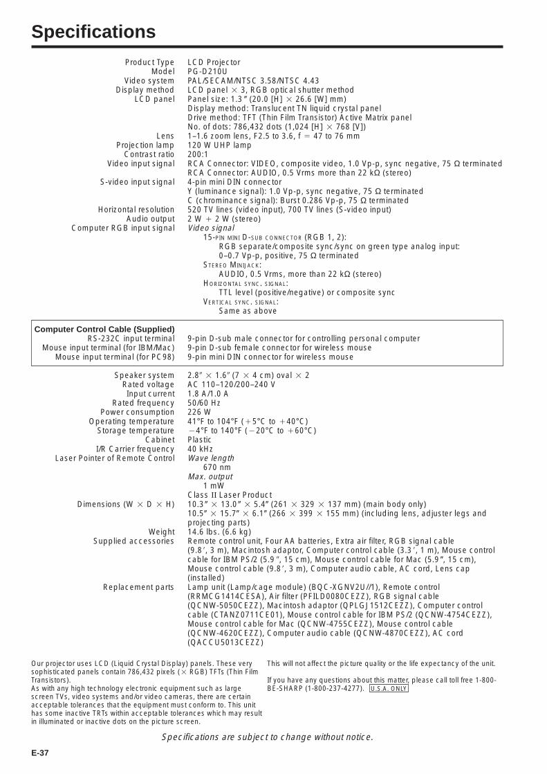
E-37
SpecificationsProduct Type
ModelVideo system
Display methodLCD panel
LensProjection lamp
Contrast ratioVideo input signal
S-video input signal
Horizontal resolutionAudio output
Computer RGB input signal
Computer Control Cable (Supplied)RS-232C input terminal
Mouse input terminal (for IBM/Mac)Mouse input terminal (for PC98)
Speaker systemRated voltageInput current
Rated frequencyPower consumption
Operating temperatureStorage temperature
CabinetI/R Carrier frequency
Laser Pointer of Remote Control
Dimensions (W 2 D 2 H)
WeightSupplied accessories
Replacement parts
LCD ProjectorPG-D210UPAL/SECAM/NTSC 3.58/NTSC 4.43LCD panel 2 3, RGB optical shutter methodPanel size: 1.3 ( (20.0 [H] 2 26.6 [W] mm)Display method: Translucent TN liquid crystal panelDrive method: TFT (Thin Film Transistor) Active Matrix panelNo. of dots: 786,432 dots (1,024 [H] 2 768 [V])1–1.6 zoom lens, F2.5 to 3.6, f 4 47 to 76 mm120 W UHP lamp200:1RCA Connector: VIDEO, composite video, 1.0 Vp-p, sync negative, 75 Ω terminatedRCA Connector: AUDIO, 0.5 Vrms more than 22 kΩ (stereo)4-pin mini DIN connectorY (luminance signal): 1.0 Vp-p, sync negative, 75 Ω terminatedC (chrominance signal): Burst 0.286 Vp-p, 75 Ω terminated520 TV lines (video input), 700 TV lines (S-video input)2 W ` 2 W (stereo)Video signal
15-PIN MINI D-SUB CONNECTOR (RGB 1, 2):RGB separate/composite sync/sync on green type analog input:0–0.7 Vp-p, positive, 75 Ω terminated
STEREO MINIJACK:AUDIO, 0.5 Vrms, more than 22 kΩ (stereo)
HORIZONTAL SYNC. SIGNAL:TTL level (positive/negative) or composite sync
VERTICAL SYNC. SIGNAL:Same as above
9-pin D-sub male connector for controlling personal computer9-pin D-sub female connector for wireless mouse9-pin mini DIN connector for wireless mouse
2.89 2 1.69 (7 2 4 cm) oval 2 2AC 110–120/200–240 V1.8 A/1.0 A50/60 Hz226 W41°F to 104°F (`5°C to `40°C)14°F to 140°F (120°C to `60°C)Plastic40 kHzWave length
670 nmMax. output
1 mWClass II Laser Product10.3 ( 2 13.0 ( 2 5.4( (261 2 329 2 137 mm) (main body only)10.5( 2 15.7( 2 6.1( (266 2 399 2 155 mm) (including lens, adjuster legs andprojecting parts)14.6 lbs. (6.6 kg)Remote control unit, Four AA batteries, Extra air filter, RGB signal cable(9.88, 3 m), Macintosh adaptor, Computer control cable (3.3 8, 1 m), Mouse controlcable for IBM PS/2 (5.9 9, 15 cm), Mouse control cable for Mac (5.9 (, 15 cm),Mouse control cable (9.88, 3 m), Computer audio cable, AC cord, Lens cap(installed)Lamp unit (Lamp/cage module) (BQC-XGNV2U//1), Remote control(RRMCG1414CESA), Air filter (PFILD0080CEZZ), RGB signal cable(QCNW-5050CEZZ), Macintosh adaptor (QPLGJ1512CEZZ), Computer controlcable (CTANZ0711CE01), Mouse control cable for IBM PS/2 (QCNW-4754CEZZ),Mouse control cable for Mac (QCNW-4755CEZZ), Mouse control cable(QCNW-4620CEZZ), Computer audio cable (QCNW-4870CEZZ), AC cord(QACCU5013CEZZ)
This will not affect the picture quality or the life expectancy of the unit.
If you have any questions about this matter, please call toll free 1-800-BE-SHARP (1-800-237-4277). U.S.A. ONLY
Our projector uses LCD (Liquid Crystal Display) panels. These verysophisticated panels contain 786,432 pixels (2 RGB) TFTs (Thin FilmTransistors).As with any high technology electronic equipment such as largescreen TVs, video systems and/or video cameras, there are certainacceptable tolerances that the equipment must conform to. This unithas some inactive TRTs within acceptable tolerances which may resultin illuminated or inactive dots on the picture screen.
Specifications are subject to change without notice.
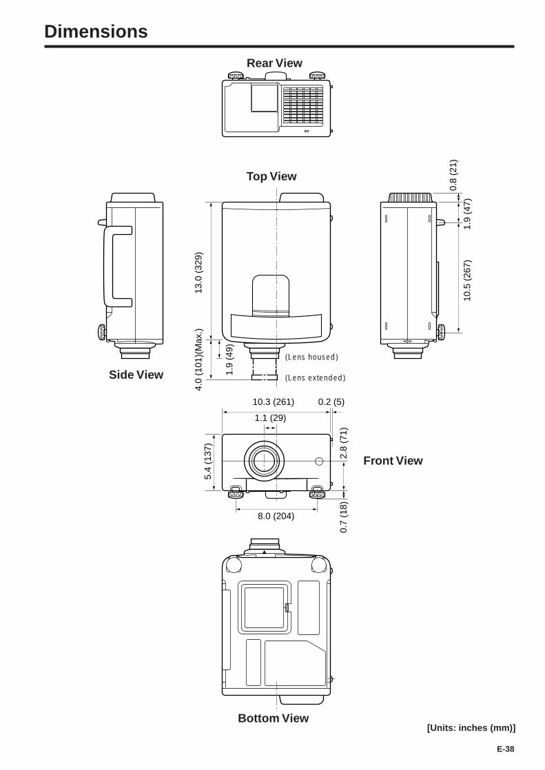
E-38
10.3 (261) 0.2 (5)
4.0
(101
)(M
ax.)
1.9
(49)
10.5
(26
7)1.
9 (4
7)
0.8
(21)
13.0
(32
9)
1.1 (29)
2.8
(71)
0.7
(18)
8.0 (204)
5.4
(137
)
Dimensions
Side View
(Lens housed)
(Lens extended)
[Units: inches (mm)]
Front View
Rear View
Top View
Bottom View

SHARP CORPORATIONOSAKA, JAPAN
Printed in JapanImprimé au JaponImpreso en JapónTINS-6785CEZZT2184-A9P06-JWG

![2012 UNDERSTANDING LCD T-CON TRAINING · PDF file2012 UNDERSTANDING LCD T CON LG No.1 2012 UNDERSTANDING LCD T- ... What is the purpose of the Blue LED on some T-CONs? [Pg 36]](https://img.dokumen.tips/doc/110x75/5a738eeb7f8b9a63638b534a/2012-understanding-lcd-t-con-training-2012-understanding-lcd-t-con-lg-no1.jpg)