Embed Size (px)
Citation preview

"Holderbank" Cement Seminar 2000
Materials Technology I- Raw Materials Management
Quarry Engineering and Design
Clemens Mann MT/CTS/HMC.
1. Introduction240
2. QUARRY DESIGN 240
2.1 Maximum Final Depth 241
2.2 Overall Slope Angle for Final Pit walls 241
2.3 Bench Height 242
3. Quarry Engineering 243
3.1 Quarry System 243
3.1.1 Ripping 243
3.1.2 Dozing 244
3.1.3 In-Pit Crushing 245
3.1.4 Glory hole 246
3.2 Haul road design 246
3.2.1 Grade 247
3.2.2 Width 247
3.2.3 Location 247
3.2.4 Safety 247
3.2.5 Calculation of truck capacity 247
3.3 Dewatering 247
4. Visualisation of quarry development 248
5. Conclusion 250
PREFERENCES 250
© Holderbank Management & Consulting, 2000 Pa9e 239

"Holderbank" Cement Seminar 2000Materials Technology I
- Raw Materials Management
1. INTRODUCTION
With QSO-Expert a global strategy for the optimum utilisation of the deposit can be
selected. Based on that strategy long term mine plans (periods of 10, 5 or single years) are
developed to investigate how the exploitation should proceed so that the optimum strategy
can be fulfilled period per period. These QSO plans are then transferred into topographical
maps showing the quarry development.
The objectives of Quarry Engineering and Design (QED) can be summarised as follows:
• to set up a technical design for the quarry
• to generate topographical maps of the quarry development
• to include important technical features especially haul roads, dumps, dewatering
systems and
• to visualise the quarry development in a most realistic way.
QED also includes engineering work of the quarry planning such
• selection of a quarry system
• haul road design
• dewatering concept
The quarry plans show the future development of the quarry in ail necessary detail. They are
used for
• strategic decisions (acquisition of property, location of crushers, construction of haul
roads and waste dumps, investment for mobile equipment).
• control of exploitation progress
• environmental related planning (rehabilitation, visibility analysis, etc.) and
• the mining permission procedure.
2. QUARRY DESIGN
Before starting with the development of long-term mine plans, some basic design features
for the quarry have to be set up. The design features determine the geometrical shape of
the quarry. The main parameters are:
•
•
quarry limits
maximum final depth
overall slope angle
bench height
Page 240 © Holderbank Management & Consulting, 2000
"Holderbank" Cement Seminar 2000
Materials Technology I- Raw Materials Management
'HOLDERBANK'
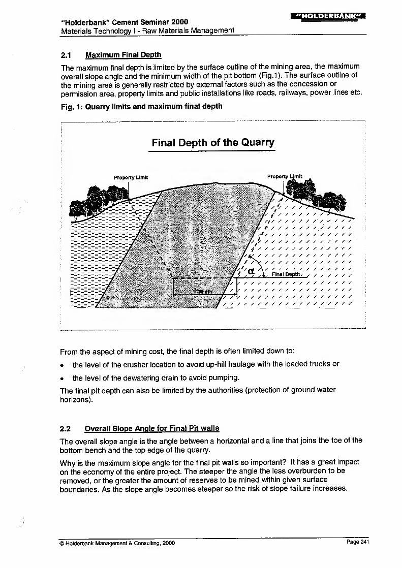
2.1 Maximum Final Depth
The maximum final depth is limited by the surface outline of the mining area, the maximum
overall slope angle and the minimum width of the pit bottom (Fig.1). The surface outline of
the mining area is generally restricted by external factors such as the concession or
permission area, property limits and public installations like roads, railways, power lines etc.
Fig. 1 : Quarry limits and maximum final depth
Final Depth of the Quarry
Property Limit Property Limit
From the aspect of mining cost, the final depth is often limited down to:
• the level of the crusher location to avoid up-hill haulage with the loaded trucks or
• the level of the dewatering drain to avoid pumping.
The final pit depth can also be limited by the authorities (protection of ground water
horizons).
2.2 Overall Slope Angle for Final Pit walls
The overall slope angle is the angle between a horizontal and a line that joins the toe of the
bottom bench and the top edge of the quarry.
Why is the maximum slope angle for the final pit walls so important? It has a great impact
on the economy of the entire project. The steeper the angle the less overburden to be
removed, or the greater the amount of reserves to be mined within given surface
boundaries. As the slope angle becomes steeper so the risk of slope failure increases.
© Holderbank Management & Consulting, 2000 Page 241

•Holderbank" Cement Seminar 2000—j:[ *
],?:^ H:y-1i'li
<iaMaterials Technology I
- Raw Materials Management
The stability of a slope is defined as a safety factor:
Sum of resisting forces
Factor of safety =
Sum of moving forces
The resisting forces depend on the friction angle and the cohesion of the material. As a first
estimation, we calculate, for the final pit walls in limestone quarries, an overall slope angle in
the range of 50° to 60°. Depending on the exact geological conditions (joints and fissures)
and the influence of water, the maximum angle can be lower or higher. Different types of
rock have different stabilities. Therefore, a severe geotechnical study is recommended to
determine the overall slope angle. This is also most relevant for the waste dump.
Slope angle for a bench system during quarry operation is normally much lower than thefinal angle because a certain bench width is required for the manoeuvrability of the mobileequipment.
2.3 Bench Height
The bench height is one of the most important design parameters of a quarry, because it
strongly influences all sectors of the mining operation. Therefore, the selection of the correctbench height is an important task for the planning engineer, in order to optimise the quarryoperation.
Of course the bench height has to be selected in accordance with mining laws or safetyregulations which limit, in many countries, the bench height to a certain maximum (e.g.
Switzerland 40 m).
Quarry and pit operators often have divergent views about bench height; while some favourhigh benches from 20 to 30 m, others feel very strongly that bench height should bedesigned from 10 to 15 m.
Lower bench height has the following advantages:
• greater selectivity of rock excavation
• greater drillhole accuracy
• higher penetration rates over the hole
Their disadvantages are:
• construction and maintenance of more benches
• more pre-stripping at lower working slope angle
• greater difference of haulage level for down-hill haulage
• limited to a certain drillhole size
• more drill down time for shifting the drill rig
• more subdrilling
• more boulders from the top of the benches
• higher consumption of detonators
Page 242 © Holderbank Management & Consulting, 2000

i ;r.n.»;j:MTrcai"Holderbank" Cement Seminar 2000
Materials Technology I- Raw Materials Management
A general value of the optimum bench height which is valid for all quarries can not be
calculated. The suitable bench height has to be selected individually for each case.
However, experience in recent years has shown that in our industry there is a tendency to
lower benches with a height of about 10 to 15 m.
3. QUARRY ENGINEERING
QED also includes engineering work for quarry planning such as
• selection of a quarry system
• haul road design
• dewatering concept
3.1 Quarry System
In our quarries, we have in most cases a system which consists of a drilling/blasting and a
loader/truck operation. Sometimes the quarry planning requires also the selection of a
different mining system. Because the mining system has a strong influence on the way in
which the quarry can be developed and what quality can be produced, it can not be selected
without considering the quality aspects.
3.1.1 Ripping
As an alternative to a drilling/blasting operation ripping can be used in soft rock (Fig.2).
Ripping has the advantages of
• no permit, transport, storage and handling of explosives are necessary
• no ground vibrations, no air blast occur
• no specially trained personnel required and
• a continuous operation
The main question is: Can the rock be ripped? As a rule of thumb it can be stated that
material up to a seismic velocity of 2.000 m/s is rippable, but other factors such as fractures
and weaknesses, weathering, stratification and brittleness are also very important.
A rock mechanic analysis, a geological site investigation and a seismic analysis may give
good indications, but only a site test can prove the rippability of the rock. Finally, a cost
comparison has to show whether ripping provides cost benefits.
© Holderbank Management & Consulting, 2000 Pa9e 243

"Holderbank" Cement Seminar 2000Materials Technology I
- Raw Materials Management
!MM=<;l=M?rT
Fig. 2: Dozer with ripper
^:;>
»-iP*ii^a"»>"flags'-* ?^-..
3.1.2 Dozing
Normally the haul road leads to all benches, so that the rock can be loaded and transported
from each bench. As an alternative, the muckpile is pushed by a dozer over the crest of the
bench and then loaded at the pit bottom into trucks.
The advantages of this method are that the haulage distances and the required number of
trucks are reduced, and the construction of a wide haul road to the upper benches is not
necessary. This results in low mining costs. The disadvantages are: reduced safety, poor
quality control by segregation, selective mining is difficult, less flexibility in face advance,
more dust and more fines.
Page 244 © Holderbank Management & Consulting, 2000

"Holderbank" Cement Seminar 2000
Materials Technology I- Raw Materials Management
!M*.H;W:V«rca
3.1.3 In-Pit Crushing
Haulage in the quarry is normally done by large trucks. The alternative is a combination of
an in-pit crusher and conveyor belt.
While a truck system offer:
• high flexibility
• high availability
• low initial investment
it has relatively high operating costs due to:
• high energy consumption
• each truck needs an operator
• high maintenance effort (engine, tyres, brakes etc.)
Furthermore trucks necessitate the construction of a wide and smooth haul road, and are
less safe, particularly at night and with poor weather conditions.
For this reason, many large scale open pit mines have installed in-pit crushing systems in
recent years, to reduce their truck fleets and haulage costs.
There are several kinds of in-pit crushing systems:
• fully mobile system which is fed directly at the face (Fig.3)
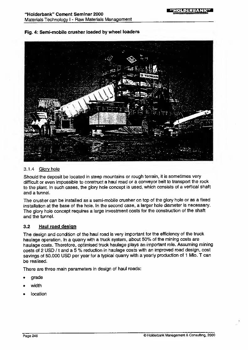
• semi-mobile system which is fed by wheel loaders (Fig.4)
• semi-mobile system which is fed by trucks
If a stationary crusher is used, the location of the installation is of primary importance, as it
determines the quarry operation over a long period of time.
Fig. 3: Fully mobile crusher loaded by face shovel
© Holderbank Management & Consulting, 2000 Page 245
"Holderbank" Cement Seminar 2000
Materials Technology I - Raw Materials Management
Fig. 4: Semi-mobile crusher loaded by wheel loaders
3.1.4 Glory hole
Should the deposit be located in steep mountains or rough terrain, it is sometimes very
difficult or even impossible to construct a haul road or a conveyor belt to transport the rock
to the plant. In such cases, the glory hole concept is used, which consists of a vertical shaft
and a tunnel.
The crusher can be installed as a semi-mobile crusher on top of the glory hole or as a fixed
installation at the base of the hole. In the second case, a larger hole diameter is necessary.
The glory hole concept requires a large investment costs for the construction of the shaft
and the tunnel.
3.2 Haul road design
The design and condition of the haul road is very important for the efficiency of the truck
haulage operation. In a quarry with a truck system, about 50% of the mining costs are
haulage costs. Therefore, optimised truck haulage plays an important role. Assuming mining
costs of 2 USD / 1 and a 5 % reduction in haulage costs with an improved road design, cost
savings of 50.000 USD per year for a typical quarry with a yearly production of 1 Mio. T can
be realised.
There are three main parameters in design of haul roads:
• grade
• width
• location
Page 246 © Holderbank Management & Consulting, 2000
"Holderbank" Cement Seminar 2000 ==Materials Technology I
- Raw Materials Management
3.2.1 Grade
Generally, the best road grade lies in the range of 8 - 12 % for regular rear-dump trucks.
Where climatic conditions are severe (excessive snow or rain) the tendency is to reduce the
grade. Articulated haul trucks can work in severe terrain conditions, and can cope with
steeper grades (25%).
3.2.2 Width
The width of the haul road should be 3 - 3.5 times that of the truck width to allow safe two
lane truck traffic. The space required for the installation of protection berms and drains must
also be added to the total width of the haul road.
3.2.3 Location
Location of the haul road is perhaps the most difficult part. The final haul road should be
established as soon as possible to avoid construction of temporary roads, and the line of the
haul road should result in short haulage distances. A good practice is to align the haul road
along a final slope, because the haul road design influences the long-term planning, both of
which must be made in accordance with each other.
When deciding on the location of the haul road, it is also important to position the road
relative to the usable / waste contact. The haul road width normally exceeds final berm
width, and consequently if the haul road is positioned in such a way that no reserves are to
be lost, then additional waste has to be removed. The alternative is to select a location on
usable reserves so that no additional waste removal is required. The positioning of the road
will be a compromise that balances additional costs for waste removal against losses on
reserves.
Sharp and steep curves on the road should be avoided as they reduce the travelling speed
and increase wear and tear on tyres and chassis. Curves should be designed with a super-
elevation to counter balance the centrifugal force.
3.2.4 Safety
Safety is an important factor on haul road design. When planning curves and hills, emphasis
has to be laid on good visibility along the haulage route. The trucks should be able to stop
within the range of visibility (Fig. 1 1). On long, steep haul roads break failures have to be
reckoned with, leading the down-hill traffic lane on the hill side of the road. Middle berms or
emergency exits are preventative measures against fatal accidents.
3.2.5 Calculation of truck capacity
Once the profile of the haul road has been established, the average cycle time can be
calculated and the required number of trucks for a given production rate can be determined.
3.3 Dewaterinq
In areas with significant rainfall, dewatering is important for a safe and efficient quarry
operation. Therefore, a good quarry design has to include a dewatering concept. That
means the benches need a slight inclination in such a way that the water runs off in a certain
direction from where it can be drained off to the quarry sump.
The drains and the sump must be designed with sufficient capacity to handle maximumexpected rainfall.
© Holderbank Management & Consulting, 2000 Page 247

"Holderbank" Cement Seminar 2000Materials Technology I - Raw Materials Management
iMl.m^VTT
4. VISUALISATION OF QUARRY DEVELOPMENT
A quarry is not a static, but a dynamic structure that greatly affects the appearance of the
surrounding area. Excellent planning is required today to cope with this continual change.
In recent years, an increased sensitivity by the public to the field of environmental protection
has resulted in approval procedures becoming increasingly difficult. A submission for
granting an extension of a mining licence can be helped by accurate computer based 3-D
quarry models and easy-to-understand illustrations. These provide detailed insight for all
steps of the quarry development, from the opening to the final recultivation. Visual displays
of the quarry make operational and environmental related planning fully transparent. In
particular the effectiveness of any measures for environmental protection can be clearly
demonstrated. This accords well with the environmental policies of many cementmanufacturers, and also saves time in the face of proliferating regulations and ever-lengthier
licencing procedures.
Fig. 5 Aerial view of a quarry. Clearly visible are the position of the crusher
(small quarry, top left), the access road and the quarry wall with aheight of up to 250m.
Page 248 © Holderbank Management & Consulting, 2000

"Holderbank" Cement Seminar 2000
Materials Technology I- Raw Materials Management
Fig. 6 Quarry at ground-level view. The main issues and the camouflage wall
are visible.
Fig. 7 This view is achieved using a combination of computer simulation and
the current appearance of a landscape using photomontage.
- -*- ;- -!
"I " ' #-' -. ' *I
siii
V.--.--' :
;.v,-:.-~--, :
; -i
.• ••. .^•'••' :
.... ..•.-..;;.; •I
© Holderbank Management & Consulting, 2000 Page 249

"Holderbank" Cement Seminar 2000~=
Materials Technology I- Raw Materials Management
Figure 5 Shows an aerial view of a quarry. This perspective is particularly suited for the
clarification of excavation concepts, from an operational viewpoint. Clearly visible in the
figure are the position of the crusher ('small quarry' top left), the access road and, in
particular, the impressive quarry wall with a height of up to 250m.
Figure 6: Shows another quarry. Unlike the first example, this is a normal ground-level view.
Here the main issues are visibility and the camouflage wall. These topics chiefly interest
authorities and the general public.
Figure 7: Is a view achieved by a combination of computer simulation and the current
appearance of the landscape using photomontage.
This is the same quarry as in Figure 5. In this project, the authorities and the general public
are taking a close and critical look at the environmental impact, so the prospects for an
excavation licence are being studied using 3-D modelling and photo-realistic visualisations.
It must be emphasised that all visual presentations are based on exact plans, which are
accurate in every detail. These plans are based on CADE (Computer Aided Deposit
Evaluation) and QSO (Quarry Scheduling Optimisation)'. They optimally satisfy long andshort-term objectives. The objectives are steady supply of good-quality raw materials, with
maximum deposit utilisation and lowest possible production cost.
QED as a further technique allows 3-D modelling and visualisation of the quarry
development. With the method of QED, the planning becomes clear and easily
understandable - clear and understandable for both the expert and the general public.
The final decision on further investments (for example for a detailed drilling campaign) will
not be reached until later, after the prospects for an excavation licence are positive.
5. CONCLUSION
To bring raw materials management into operation the following steps have to carried out:
• The general layout of the quarry and a suitable mining procedure has to be determined.
• A long-term strategy for the quarry development has to be defined, which is guided bythe optimum use of the deposit.
• More detailed periodical quarry plans have to be developed and transferred into detailed
technical quarry maps.
• Photorealistic perspective views of the quarry development are produced to support the
permitting process
Today, integrated computerised tools are used for digital terrain modelling, volumecalculations and drawing of topographical maps. With the tendency to large scale operations
and increasing environmental awareness, the necessity for reliable and detailed quarry
planning becomes increasingly evident.
6. REFERENCES
BAUMGARTNER W., Computerised raw materials management - developments andprogress. World Cement, Vol. 21, no. 5, pp. 207-213 (1990).
Page 250 © Holderbank Management & Consulting, 2000


![(Sat) (Sun) TEL:0269-23-0209 FAX:0269-26-0074 · 2020 Pfi -10-4 fil-LlñE644 200 204-2 898 filliñi*1377 035-3 fill]ñãŒJ27-11 fill-lñãfflJ38-8 3-5 103-8 0269-22-5127 0269-67-0393](https://img.dokumen.tips/doc/110x75/5f2e3a47e676e4722e1040bc/sat-sun-tel0269-23-0209-fax0269-26-0074-2020-pfi-10-4-fil-lle644-200-204-2.jpg)


![INDEX 0269 [globalgenealogy.com]](https://img.dokumen.tips/doc/110x75/61a12365dff2ee67150eb6bb/index-0269-.jpg)
