Embed Size (px)
Citation preview
@IJRTER-2016, All Rights Reserved 552
PERFORMANCE OF DIGITALIZED SECURE SYSTEM IN
VARIOUS NETWORK TOPOLOGIES
K.C.Abhilash Sam Paulstin (Assistant Professor)1, M.Ann Michle (Assistant Professor)2
1,2Department of computer science, Nanjil Catholic College of Arts and Science, Kaliyakavilai, K.K.Dist
Abstract:The issues which are related to share information in a distributed system represent a secure
transmission of data. The issues consist of self-directed entity which is transferred securely in a multi
subdivided system. The data which is transferred in different topologies are signed with the digital signature.
The signed data is securely transferred in network using different kinds of topologies. While transferring data
in a network there may be leakage of data, to overcome this leakage of data we propose digital signature
concept. When the data is transferred to the network from user, the intermediate persons cannot view the data
because while transferring the data it is partially viewable with help of partial disclosure technique. The data
which is transferred is secure and it is verified by the network whether the given data and the received data are
same.
Keywords – Digital signature, topologies, Partial disclosure.
I. INTRODUCTION In computer networking, topology refers to the layout of connected devices. Computer Network
Topology is an extension of basic Topology. This discipline examines the configuration of computer
system elements and their associated interconnections [1]. Physical Network Topology emphasizes
the hardware associated with the system including workstations, remote terminals, servers, and the
associated wiring between assets. Network topologies describe the ways in which the elements of a
network are mapped. They describe the physical and logical arrangement of the network nodes.
Logical Network Topology (also known as Signal Topology) emphasizes the representation of data
flow between nodes, not dissimilar from Graph Theory analysis. The logical topography of a
network can be dynamically reconfigured when select network equipment, such as routers, is
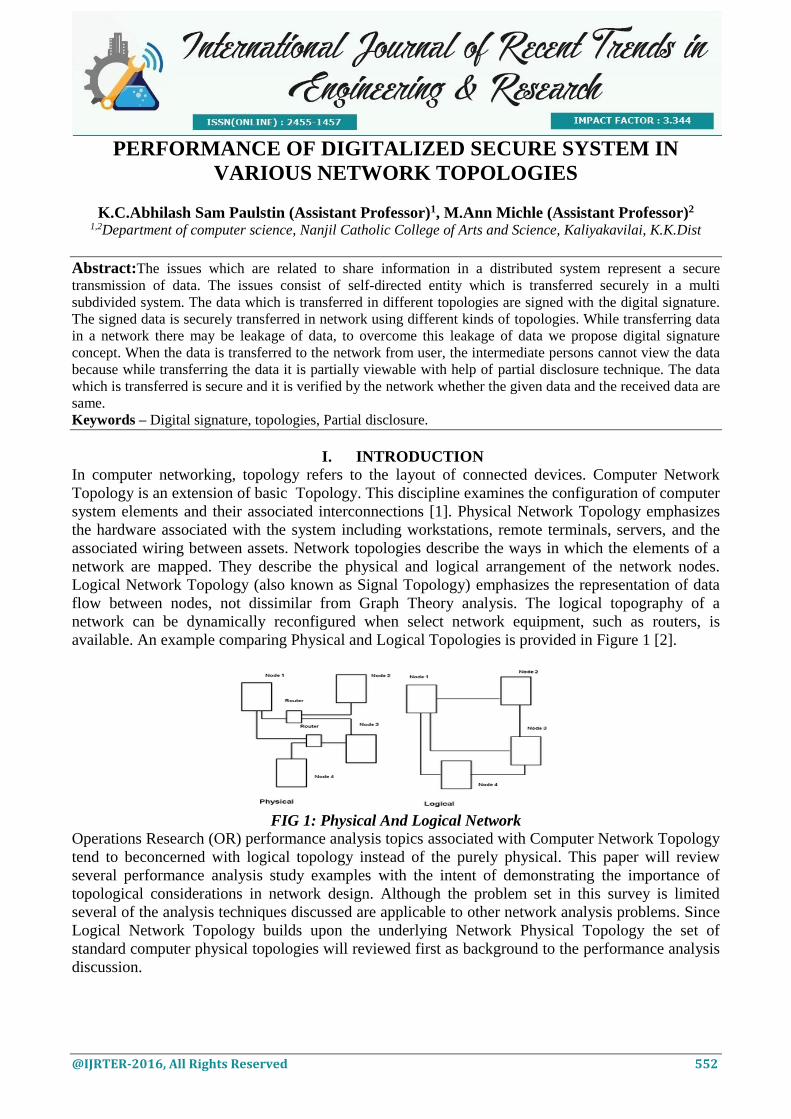
available. An example comparing Physical and Logical Topologies is provided in Figure 1 [2].
FIG 1: Physical And Logical Network
Operations Research (OR) performance analysis topics associated with Computer Network Topology
tend to beconcerned with logical topology instead of the purely physical. This paper will review
several performance analysis study examples with the intent of demonstrating the importance of
topological considerations in network design. Although the problem set in this survey is limited
several of the analysis techniques discussed are applicable to other network analysis problems. Since
Logical Network Topology builds upon the underlying Network Physical Topology the set of
standard computer physical topologies will reviewed first as background to the performance analysis
discussion.
International Journal of Recent Trends in Engineering & Research (IJRTER)
Volume 02, Issue 11; November - 2016 [ISSN: 2455-1457]
@IJRTER-2016, All Rights Reserved 553
II. DIFFERENT TOPOLOGIES
A. PHYSICALNETWORK TOPOLOGIES
1. BUS NETWORK TOPOLOGY
In Bus Network Topology a single cable is used to connect all devices on the net. This cable is often
referred to as the network Backbone. When communication occurs between nodes the device sending
the message broadcasts to all nodes on the network, but only the desired recipient digests the
message. Advantages of this type of Physical Topology include ease of installation and minimization
of the required cabling. Further, failure of a node attached to the network has no effect on other
nodes attached to the network. Also messages from one node can be seen near simultaneously by all
other nodes on the network. Disadvantages of this configuration include performance limits on the
number of network nodes, and complete network communication stoppage if the cable fails.
Advantages of bus topology are it is Cheap, easy to handle and implement, require less cable, it is
best suited for small networks. Disadvantages of bus topology are the cable length is limited. This
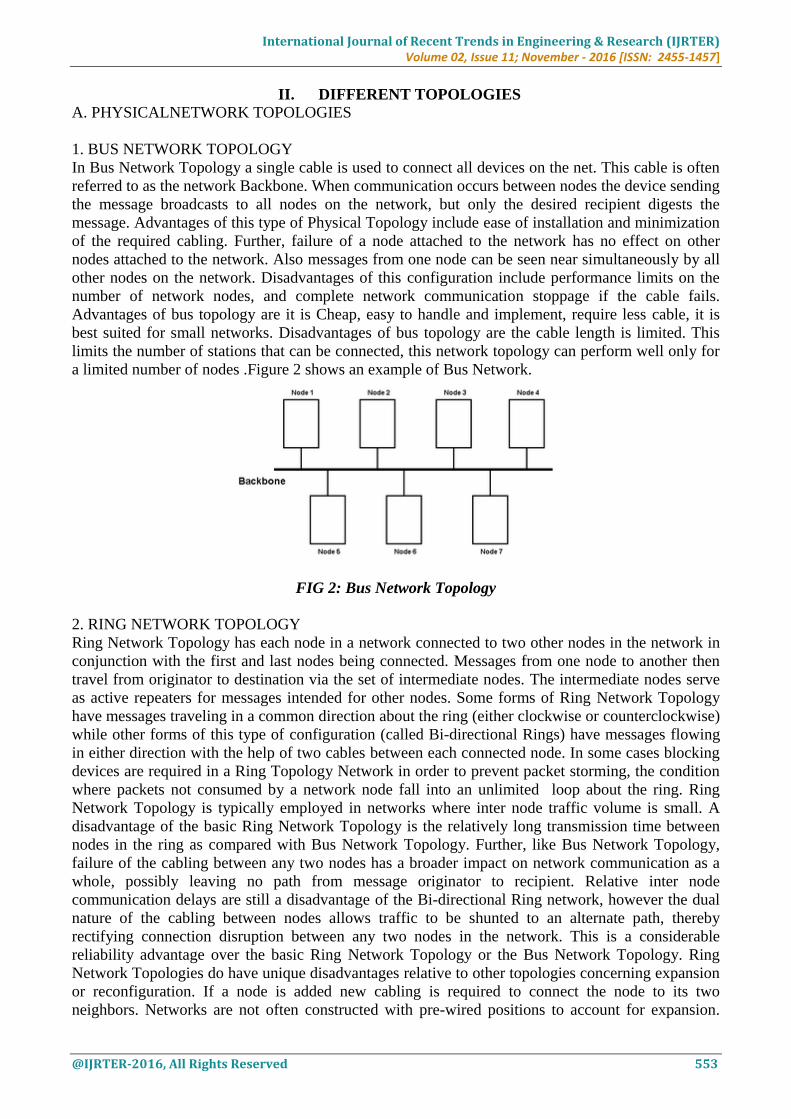
limits the number of stations that can be connected, this network topology can perform well only for
a limited number of nodes .Figure 2 shows an example of Bus Network.
FIG 2: Bus Network Topology
2. RING NETWORK TOPOLOGY
Ring Network Topology has each node in a network connected to two other nodes in the network in
conjunction with the first and last nodes being connected. Messages from one node to another then
travel from originator to destination via the set of intermediate nodes. The intermediate nodes serve
as active repeaters for messages intended for other nodes. Some forms of Ring Network Topology
have messages traveling in a common direction about the ring (either clockwise or counterclockwise)
while other forms of this type of configuration (called Bi-directional Rings) have messages flowing
in either direction with the help of two cables between each connected node. In some cases blocking
devices are required in a Ring Topology Network in order to prevent packet storming, the condition
where packets not consumed by a network node fall into an unlimited loop about the ring. Ring
Network Topology is typically employed in networks where inter node traffic volume is small. A
disadvantage of the basic Ring Network Topology is the relatively long transmission time between
nodes in the ring as compared with Bus Network Topology. Further, like Bus Network Topology,
failure of the cabling between any two nodes has a broader impact on network communication as a
whole, possibly leaving no path from message originator to recipient. Relative inter node
communication delays are still a disadvantage of the Bi-directional Ring network, however the dual
nature of the cabling between nodes allows traffic to be shunted to an alternate path, thereby
rectifying connection disruption between any two nodes in the network. This is a considerable
reliability advantage over the basic Ring Network Topology or the Bus Network Topology. Ring
Network Topologies do have unique disadvantages relative to other topologies concerning expansion
or reconfiguration. If a node is added new cabling is required to connect the node to its two
neighbors. Networks are not often constructed with pre-wired positions to account for expansion.
International Journal of Recent Trends in Engineering & Research (IJRTER)
Volume 02, Issue 11; November - 2016 [ISSN: 2455-1457]
@IJRTER-2016, All Rights Reserved 554
Advantages of ring topology are Very orderly network where every device has access to the token
and the opportunity to transmit, easier to Mange than a Bus Network, Good Communication over
long distances, handles high volume of traffic. Disadvantages of ring topology are the failure of a
single node of the network can cause the entire network to fail, the movement or changes made to
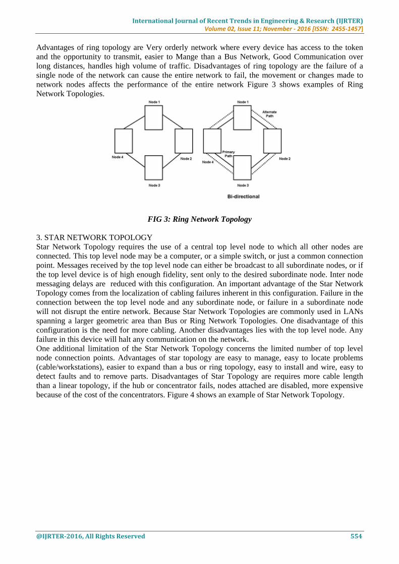
network nodes affects the performance of the entire network Figure 3 shows examples of Ring
Network Topologies.
FIG 3: Ring Network Topology
3. STAR NETWORK TOPOLOGY
Star Network Topology requires the use of a central top level node to which all other nodes are
connected. This top level node may be a computer, or a simple switch, or just a common connection
point. Messages received by the top level node can either be broadcast to all subordinate nodes, or if
the top level device is of high enough fidelity, sent only to the desired subordinate node. Inter node
messaging delays are reduced with this configuration. An important advantage of the Star Network
Topology comes from the localization of cabling failures inherent in this configuration. Failure in the
connection between the top level node and any subordinate node, or failure in a subordinate node
will not disrupt the entire network. Because Star Network Topologies are commonly used in LANs
spanning a larger geometric area than Bus or Ring Network Topologies. One disadvantage of this
configuration is the need for more cabling. Another disadvantages lies with the top level node. Any
failure in this device will halt any communication on the network.
One additional limitation of the Star Network Topology concerns the limited number of top level
node connection points. Advantages of star topology are easy to manage, easy to locate problems
(cable/workstations), easier to expand than a bus or ring topology, easy to install and wire, easy to
detect faults and to remove parts. Disadvantages of Star Topology are requires more cable length
than a linear topology, if the hub or concentrator fails, nodes attached are disabled, more expensive
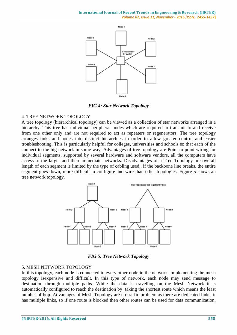
because of the cost of the concentrators. Figure 4 shows an example of Star Network Topology.
International Journal of Recent Trends in Engineering & Research (IJRTER)
Volume 02, Issue 11; November - 2016 [ISSN: 2455-1457]
@IJRTER-2016, All Rights Reserved 555
FIG 4: Star Network Topology
4. TREE NETWORK TOPOLOGY
A tree topology (hierarchical topology) can be viewed as a collection of star networks arranged in a
hierarchy. This tree has individual peripheral nodes which are required to transmit to and receive
from one other only and are not required to act as repeaters or regenerators. The tree topology
arranges links and nodes into distinct hierarchies in order to allow greater control and easier
troubleshooting. This is particularly helpful for colleges, universities and schools so that each of the
connect to the big network in some way. Advantages of tree topology are Point-to-point wiring for
individual segments, supported by several hardware and software vendors, all the computers have
access to the larger and their immediate networks. Disadvantages of a Tree Topology are overall
length of each segment is limited by the type of cabling used., if the backbone line breaks, the entire
segment goes down, more difficult to configure and wire than other topologies. Figure 5 shows an
tree network topology.
FIG 5: Tree Network Topology
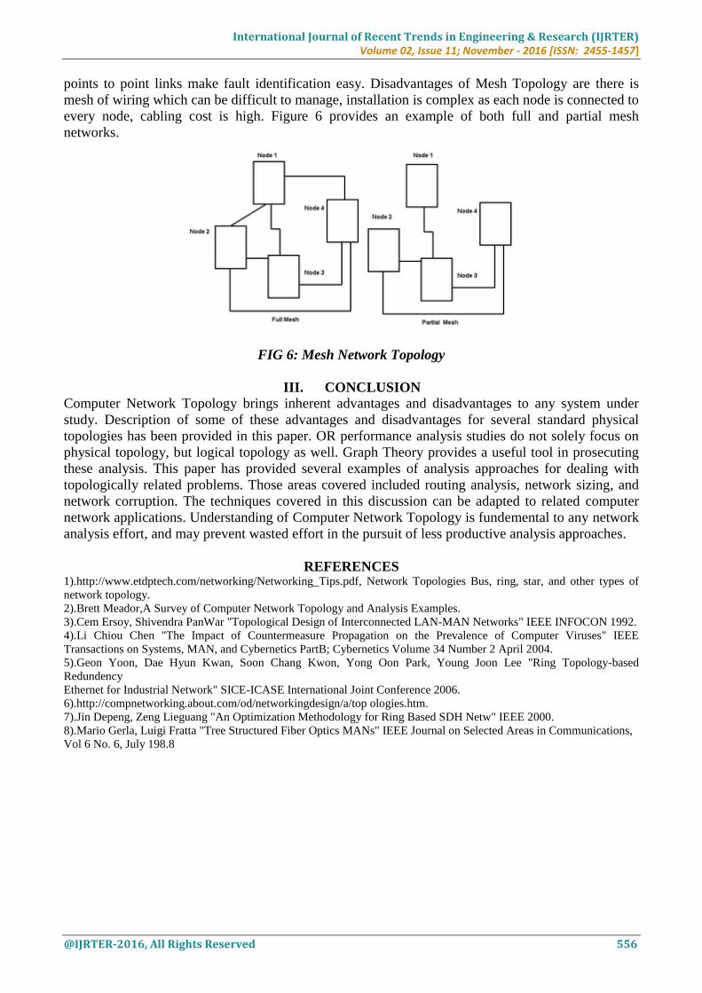
5. MESH NETWORK TOPOLOGY
In this topology, each node is connected to every other node in the network. Implementing the mesh
topology isexpensive and difficult. In this type of network, each node may send message to
destination through multiple paths. While the data is travelling on the Mesh Network it is
automatically configured to reach the destination by taking the shortest route which means the least
number of hop. Advantages of Mesh Topology are no traffic problem as there are dedicated links, it
has multiple links, so if one route is blocked then other routes can be used for data communication,
International Journal of Recent Trends in Engineering & Research (IJRTER)
Volume 02, Issue 11; November - 2016 [ISSN: 2455-1457]
@IJRTER-2016, All Rights Reserved 556
points to point links make fault identification easy. Disadvantages of Mesh Topology are there is
mesh of wiring which can be difficult to manage, installation is complex as each node is connected to
every node, cabling cost is high. Figure 6 provides an example of both full and partial mesh
networks.
FIG 6: Mesh Network Topology
III. CONCLUSION Computer Network Topology brings inherent advantages and disadvantages to any system under
study. Description of some of these advantages and disadvantages for several standard physical
topologies has been provided in this paper. OR performance analysis studies do not solely focus on
physical topology, but logical topology as well. Graph Theory provides a useful tool in prosecuting
these analysis. This paper has provided several examples of analysis approaches for dealing with
topologically related problems. Those areas covered included routing analysis, network sizing, and
network corruption. The techniques covered in this discussion can be adapted to related computer
network applications. Understanding of Computer Network Topology is fundemental to any network
analysis effort, and may prevent wasted effort in the pursuit of less productive analysis approaches.
REFERENCES 1).http://www.etdptech.com/networking/Networking_Tips.pdf, Network Topologies Bus, ring, star, and other types of
network topology.
2).Brett Meador,A Survey of Computer Network Topology and Analysis Examples.
3).Cem Ersoy, Shivendra PanWar "Topological Design of Interconnected LAN-MAN Networks" IEEE INFOCON 1992.
4).Li Chiou Chen "The Impact of Countermeasure Propagation on the Prevalence of Computer Viruses" IEEE
Transactions on Systems, MAN, and Cybernetics PartB; Cybernetics Volume 34 Number 2 April 2004.
5).Geon Yoon, Dae Hyun Kwan, Soon Chang Kwon, Yong Oon Park, Young Joon Lee "Ring Topology-based
Redundency
Ethernet for Industrial Network" SICE-ICASE International Joint Conference 2006.
6).http://compnetworking.about.com/od/networkingdesign/a/top ologies.htm.
7).Jin Depeng, Zeng Lieguang "An Optimization Methodology for Ring Based SDH Netw" IEEE 2000.
8).Mario Gerla, Luigi Fratta "Tree Structured Fiber Optics MANs" IEEE Journal on Selected Areas in Communications,
Vol 6 No. 6, July 198.8