Embed Size (px)
Citation preview

Meccanica (2013) 48:121–134DOI 10.1007/s11012-012-9588-4
Performance evaluation of electronic control suspensionfeaturing vehicle ER dampers
Kum-Gil Sung · Min-Sang Seong ·Seung-Bok Choi
Received: 8 August 2011 / Accepted: 31 July 2012 / Published online: 14 August 2012© Springer Science+Business Media B.V. 2012
Abstract This paper presents ride comfort and driv-ing stability performances of electronic control sus-pension (ECS) equipped with controllable electrorhe-ological (ER) damper and appropriate control strat-egy. In order to achieve this goal, a cylindrical typeER damper which is applicable to Macpherson struttype suspension of a mid-sized passenger vehicle isdesigned and manufactured on the basis of the re-quired damping force level of an existing passen-ger vehicle. After experimentally evaluating the field-dependent damping force and dynamic characteris-tics of the controllable ER damper, ECS consistingof sprung mass, spring, tire and controller is estab-lished in order to investigate the ride comfort anddriving stability performances. On the basis of thegoverning equation of motion of the suspension sys-tem, five control strategies (soft, hard, comfort, sportsand optimal mode) are formulated. The proposed con-trol strategies are then experimentally realized withthe quarter-vehicle ECS system. Control performancessuch as vertical acceleration of the car body and tire
K.-G. SungSchool of Mechanical and Automotive EngineeringTechnology, Yeungnam College of Science andTechnology, Daegu 705-703, Korea
M.-S. Seong · S.-B. Choi (�)Smart Structures and Systems Laboratory, Department ofMechanical Engineering, Inha University, Incheon402-751, Koreae-mail: [email protected]
deflection are evaluated in both time and frequencydomains under various road conditions. In addition,a comparative work is undertaken to investigate in-herent control characteristics of each control strat-egy.
Keywords Electrorheological (ER) fluid · ERdamper · Vehicle suspension · Electronic controlsuspension · Ride comfort · Driving stability
1 Introduction
Vehicle dynamic characteristics such as ride comfortand driving stability can normally be improved by sus-pension system [1, 2]. So for, passive oil dampers,which provide design simplicity and cost effective-ness, are widely employed for conventional vehicles.However, performance limitation is inevitable ow-ing to uncontrollable damping force. Recently, activedampers using a motor and electro-servo hydraulicvalve have gradually been introduced to achieve bet-ter ride comfort as well as better driving stability.However, design complication and high cost preventthe wide use of advanced active suspension systems.Therefore, alternative mechanisms for vehicle suspen-sion systems have been studied to replace the passiveand active dampers. Recently, the research work on vi-bration suppression for ride comfort and driving sta-bility of a vehicle system using semi-active suspen-sion has been significantly increased. A semi-active

122 Meccanica (2013) 48:121–134
suspension system using electrorheological (ER) fluidcan offer the desired performance in the active modewithout requiring large power consumption and ex-pensive hardware. ER fluid, the rheological propertiesof which can be rapidly changed by applying electricfield to the fluid domain, has been used in many de-vices such as damper [3–9], valves [10, 11], mounts[12, 13], and clutch/brake systems [14, 15]. For the lastdecade, very attractive and effective semi-active sus-pension system featuring ER fluid has been proposedby many investigators.
Nakano [3] constructed a quarter-vehicle model us-ing an ER damper and proposed two control strate-gies: constant control voltage and square root of con-trol voltage proportional to absolute velocity of un-sprung mass. Sims et al. [4] described a closed-loopcontrol strategy which is capable of linearizing theresponse of an ER long-stroke damper under experi-mental conditions. Petek et al. [5] constructed a semi-active full suspension system consisting of four ERdampers and evaluated its effectiveness for vibrationisolation. They demonstrated experimentally that un-wanted pitch, heave and roll motions of vehicle bodywere favorably suppressed using the simple skyhookcontrol algorithm. Gordaninejad et al. [6] experimen-tally evaluated the performance of cylindrical, multi-electrode ER dampers under force vibration. They pro-posed simple control algorithms such as bang-bangand linear proportional controller, and experimentallydemonstrated the successful implementation of thecontrol schemes to a closed-loop system. Choi et al.[7–9] proposed a cylindrical ER damper for passen-ger vehicle and its superior controllability of damp-ing force was proved in the laboratory. Choi et al. [16]proposed control algorithm of ER suspension systemfor vehicle stability via HILS (Hardware-in-the-LoopSimulation). From these research works, the effective-ness of ER damper has been proved for vibration con-trol of automotive vehicles.
In semi-active vehicle suspension using ER damper,the research work on experimental investigation forperformance evaluation of both ride comfort and driv-ing stability performances is rare. However, in orderto successfully commercialize the ER damper, its ridecomfort and driving stability performances of auto-motive vehicles should be undertaken simultaneously.Consequently, the main contribution of this work isto experimentally demonstrate suspension control per-formance of electronic control suspension (ECS) for
Fig. 1 Schematic configuration of the proposed ER damper
both ride comfort and driving stability using five con-trol strategies (soft, hard, comfort, sports and optimalmode). For this purpose, continuously controllable ERdamper is designed and manufactured on the basis ofthe required damping force level for a mid-sized ex-isting passenger vehicle. After experimentally evalu-ating the field-dependent damping force and dynamiccharacteristics of the manufactured ER damper, the ERdamper is incorporated to a quarter-vehicle suspensionsystem which is composed of sprung mass, spring andtire in order to investigate the ride comfort and driv-ing stability performances of ECS. Subsequently, fivecontrol strategies are implemented for the realizationof the quarter-vehicle ER suspension system. Controlperformances of the ECS equipped with ER dampersuch as vertical acceleration of sprung mass and tiredeflection are experimentally evaluated under bumpand random road conditions in order to investigate thepractical feasibility.
2 Electrorheological damper
The schematic configuration of the proposed ERdamper which is applicable to Macpherson strut typesuspension of mid-sized passenger vehicle is shownin Fig. 1. The ER damper is composed of the cylin-der, piston and gas chamber. The floating piston be-tween the cylinder and the gas chamber is also usedin order to compensate for the volume induced by themotion of the piston. The cylinder and the gas cham-ber in the ER damper are fully filled with the ER fluidand nitrogen gas, respectively. The ER damper is di-vided into upper and lower chambers by the piston,

Meccanica (2013) 48:121–134 123
and the ER fluid flows through the annular duct be-tween the inner and outer cylinders from one chamberto the other by the motion of the piston. Thus, the op-erating mode of the proposed ER damper is flow modein which two electrodes are fixed. The control voltagegenerated by a high voltage supply unit is connectedto the inner cylinder and the ground voltage is con-nected to the outer cylinder. In the absence of the elec-tric field, the ER damper produces a damping forcecaused only by fluid viscous resistance. However, if acertain level of the electric field is supplied to the ERdamper, the ER damper produces an additional damp-ing force owing to the yield stress of the ER fluid.This damping force of the ER damper can be continu-ously tuned by controlling the intensity of the electricfield.
In order to simplify the analysis of the ER damper,it is assumed that the ER fluid is incompressible andthat pressure in one chamber is uniformly distributed.The pressure drops due to the geometric shape of theannular duct and the fluid inertia are assumed to benegligible. For laminar flow in the annular duct, thefluid resistance [17] is given by
Re = 8ηL
π[R4
o − R4i − (R2
o−R2i )2
ln(Ro/Ri)
] (1)
where η is the viscosity of the ER fluid and L is thelength of the annular duct. Ro and Ri are the innerradius of the outer electrode and outer radius of the in-ner electrode, respectively. By assuming that the gasdoes not exchange much heat with its surroundings,and hence considering its relation as adiabatic varia-tion, the compliance of the gas chamber is obtainedby
Cg = V0
P0κ(2)
where V0 and P0 are the initial volume and pressureof the gas chamber, respectively, and κ is the specificheat ratio. On the other hand, the pressure drop dueto the increment of the yield stress of the ER fluid isgiven by
PER = cL
hτy(E) = cL
hαEβ (3)
where c is the coefficient that depends on flow veloc-ity profile and has a value range from 2.0 to 3.0, h
is the gap of the annular duct, and τy(E) is the yieldstress caused by the electric field (E). The α and β
Fig. 2 Photograph of the manufactured ER damper
Table 1 Design parameters of the ER damper
Parameter Value
Duct length (L) 253 mm
Piston area (Ap) 1335.76 mm2
Piston rod area (Ar ) 380.13 mm2
Electrode width (b) 148.03 mm
Maximum stroke 164 mm
are intrinsic values of the ER fluid to be experimen-tally determined. Therefore, the damping force of theproposed ER damper can be written as
FD = kexp + cexp + FER (4)
where
ke = A2r
Cg
, ce = (Ap − Ar)2Re
FER = (Ap − Ar)PER sgn(xp)
where xp and xp are the piston displacement andvelocity, respectively. Ap and Ar represent the pis-ton and piston rod areas, respectively, and sgn(·) is asignum function.
The photograph of the manufactured ER damper isshown in Fig. 2. The principal design parameters ofthe manufactured ER damper, which can be appliedto a mid-sized commercial passenger vehicle, are pre-sented in Table 1. The damping force characteristicsare measured by own work and Fig. 3 presents themeasured and analyzed damping force (FD) charac-teristics of the ER damper with respect to the pistonvelocity at various electric fields. This is obtained bycalculating the maximum damping force at each ve-locity. The piston velocity is changed by increasingthe excitation frequency from 0.5 to 4.0 Hz, while theexcitation amplitude is kept constant ±20 mm. This

124 Meccanica (2013) 48:121–134
Fig. 3 Field-dependent damping forces of the ER damper
Fig. 4 Time responses of the ER damper
type of plot is frequently used in the damper man-ufacturing industry to evaluate the level of dampingperformance. It is clearly observed that the dampingforce is increased as the electric field increases, as ex-pected. As a specific case for an ER damper, the damp-ing force of 299.3 N at a piston velocity of 0.5027 m/sis increased up to 1138.0 N by applying an electricfield 3.0 kV/mm. It is noted that the solid line in Fig. 3is the damping force curve of a passive oil damperfor the commercial passenger vehicle (Magnus, GMDAEWOO Auto and Technology).
In order to measure the time constant, the ERdamper is vertically excited by hydraulic actuator. Theexcitation condition is sinusoidal movement with 1 Hzand ±20 mm. The measurement result is shown inFig. 4. It can be found that the time constant is about18 ms, which is obtained by inspecting the requiredtime when the damping force reaches 63.2 percent ofits final steady state value. Figure 5 presents the dy-namic bandwidth of the damping force in frequencydomain. By sweeping the input field frequency withthe magnitude of 3 kV/mm, the dynamic bandwidth is
Fig. 5 Dynamic bandwidth of the ER damper in frequency do-main
Table 2 Curve fitting parameters of the damping force
Parameter Value Parameter Value
ce,pr 101.15 ce,po 284.49
ap 97.06 an 151.78
bp 1.79 bn 1.17
obtained. It is identified that the dynamic bandwidthof the proposed ER damper is about 33 Hz at −3 dB.Thus, both the vehicle body mode (1–2 Hz) and thewheel mode (10–15 Hz), which are directly related toride comfort and driving stability respectively, of thepassenger vehicle can be effectively controlled by em-ploying the proposed ER damper. Figure 6 presentsthe measured power consumption of the ER damperthat is required to generate a certain level of dampingforce. The damping force and the required voltage areconverted to mechanical and electrical energy respec-tively. About 2.7 W is required to generate the damp-ing force of 1138.0 N at piston velocity of 0.5027 m/s.In practice, this amount of power can be sufficientlysupplied from the commercial battery of passenger ve-hicles.
In order to evaluate suspension control perfor-mance in next section, the measured damping forceshown in Fig. 3 is fitted using the bi-viscous curveshown in Fig. 7. From the curve fitting, the effectivedamping coefficient and controllable damping force ofthe ER damper can be expressed as follows
ce =
⎧⎪⎨
⎪⎩
ce,pr for − xp,t ≤ xp < xp,t
ce,pr xp,t /xp + ce,po
for xp ≥ xp,t or xp < −xp,t
(5)

Meccanica (2013) 48:121–134 125
FER =
⎧⎪⎪⎪⎪⎨
⎪⎪⎪⎪⎩
apEbp · xp,t for xp,t ≤ xp
apEbp · xp for 0 ≤ xp < xp,t
anEbn · xp for − xp,t ≤ xp < 0
anEbn · xp,t for xp < −xp,t
(6)
where xp,t is the transition piston velocity. ce,pr andce,po are the preyield and postyield damping coeffi-cient, respectively. ap , an, bp and bn are the intrinsicvalues of the ER damper to be experimentally deter-
Fig. 6 Power consumption of the ER damper
mined. The curve fitting parameters for the effectivedamping coefficient and controllable damping forceare listed in Table 2. On the other hand, from the re-sponse result shown in Fig. 5, the static expression ofthe damping force and input current given by aboveequation can be modified as follows to take into ac-count for the dynamic characteristics
τd
dtFER + FER
=
⎧⎪⎪⎪⎨
⎪⎪⎪⎩
apEbp · xp,t for xp,t ≤ xp
apEbp · xp for 0 ≤ xp < xp,t
anEbn · xp for − xp,t ≤ xp < 0
anEbn · xp,t for xp < −xp,t
(7)
where τ is the time constant of the ER damper. Thedynamic model of the ER damper will be incorporatedwith the suspension model in next section.
3 Control strategies
Figure 8 shows the quarter-vehicle model of the semi-active ER suspension system, which has two degreesof freedom. Here, ms and mu represent the sprungmass and unsprung mass, respectively. The spring forthe suspension is assumed to be linear and the tireis also modeled as linear spring component. Now, byconsidering the dynamic relationship, the state-spacecontrol model is expressed for the quarter-vehicle ERsuspension system as follows
x = Ax + Bu + Lzr
y = Cx(8)
where
x = [zs zs zu zu FER]T
Fig. 7 Bi-viscous fit of damping force for the ER damper

126 Meccanica (2013) 48:121–134
Fig. 8 The quarter-vehicle model of the ER suspension system
A =
⎡
⎢⎢⎢⎢⎢⎢⎢⎣
0 1 0 0 0
− ks
ms− cs
ms
ks
ms
cs
ms− 1
ms
0 0 0 1 0ks
mu
cs
mu− kt+ks
mu− cs
mu
1mu
0 0 0 0 − 1τ
⎤
⎥⎥⎥⎥⎥⎥⎥⎦
,
B = [0 0 0 0 1
τ
]T,
L = [0 0 0 kt
mu0]T
,
C = [1 0 0 0 0]where ks is the total stiffness coefficient of the sus-pension, including the effective stiffness ke of the ERdamper in Eq. (4), cs is the damping coefficient of thesuspension and is assumed to be equal to ce, kt is thevertical stiffness of the tire, and zs , zu and zr are thevertical displacements of sprung mass, unsprung mass,and road excitation, respectively.
In this study, five control strategies for ECS equip-ped with ER damper are adopted: soft, hard, comfort,sports and optimal mode. In case of soft mode whichdirectly means minimum damping force, a constantinput field 0.0 kV/mm is applied to ER damper inorder to improve ride comfort instead of driving sta-bility, while 3.0 kV/mm is supplied in order to en-hance driving stability instead of ride comfort in hardmode which directly means maximum damping force.In other hand, in order to realize for comfort, sportsand optimal modes, the skyhook controller is adopted.It is well known that the logic of the skyhook con-
Fig. 9 Performance indexes of the quarter-vehicle ER suspen-sion system
troller is simple and easy to implement to real field.The desired damping force is set by
u = Csky · zs (9)
where Csky is the control gain which physically indi-cates the damping coefficient. Equations (8) and (9)are used for computer simulation to determine appro-

Meccanica (2013) 48:121–134 127
Fig. 10 The experimental apparatus for the ER suspension system
128 Meccanica (2013) 48:121–134
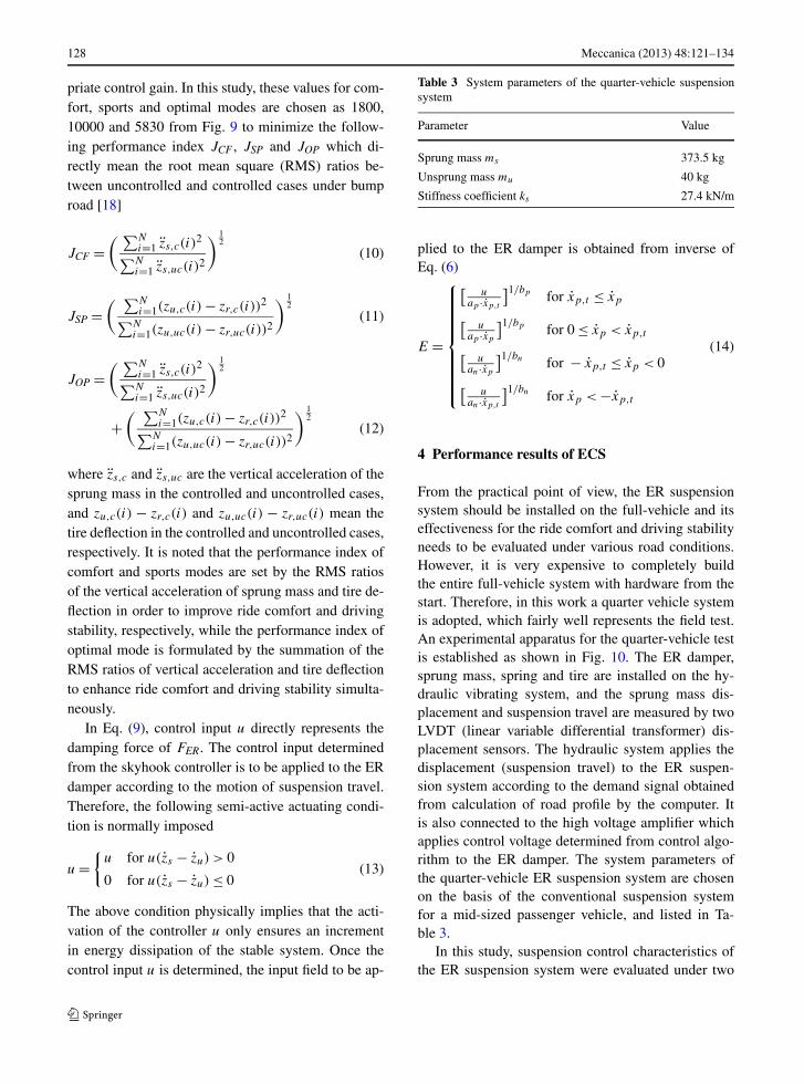
priate control gain. In this study, these values for com-fort, sports and optimal modes are chosen as 1800,10000 and 5830 from Fig. 9 to minimize the follow-ing performance index JCF , JSP and JOP which di-rectly mean the root mean square (RMS) ratios be-tween uncontrolled and controlled cases under bumproad [18]
JCF =( ∑N
i=1 zs,c(i)2
∑Ni=1 zs,uc(i)2
) 12
(10)
JSP =( ∑N
i=1(zu,c(i) − zr,c(i))2
∑Ni=1(zu,uc(i) − zr,uc(i))2
) 12
(11)
JOP =( ∑N
i=1 zs,c(i)2
∑Ni=1 zs,uc(i)2
) 12
+( ∑N
i=1(zu,c(i) − zr,c(i))2
∑Ni=1(zu,uc(i) − zr,uc(i))2
) 12
(12)
where zs,c and zs,uc are the vertical acceleration of thesprung mass in the controlled and uncontrolled cases,and zu,c(i) − zr,c(i) and zu,uc(i) − zr,uc(i) mean thetire deflection in the controlled and uncontrolled cases,respectively. It is noted that the performance index ofcomfort and sports modes are set by the RMS ratiosof the vertical acceleration of sprung mass and tire de-flection in order to improve ride comfort and drivingstability, respectively, while the performance index ofoptimal mode is formulated by the summation of theRMS ratios of vertical acceleration and tire deflectionto enhance ride comfort and driving stability simulta-neously.
In Eq. (9), control input u directly represents thedamping force of FER. The control input determinedfrom the skyhook controller is to be applied to the ERdamper according to the motion of suspension travel.Therefore, the following semi-active actuating condi-tion is normally imposed
u ={
u for u(zs − zu) > 0
0 for u(zs − zu) ≤ 0(13)
The above condition physically implies that the acti-vation of the controller u only ensures an incrementin energy dissipation of the stable system. Once thecontrol input u is determined, the input field to be ap-
Table 3 System parameters of the quarter-vehicle suspensionsystem
Parameter Value
Sprung mass ms 373.5 kg
Unsprung mass mu 40 kg
Stiffness coefficient ks 27.4 kN/m
plied to the ER damper is obtained from inverse ofEq. (6)
E =
⎧⎪⎪⎪⎪⎪⎪⎪⎪⎨
⎪⎪⎪⎪⎪⎪⎪⎪⎩
[u
ap ·xp,t
]1/bp for xp,t ≤ xp
[u
ap ·xp
]1/bp for 0 ≤ xp < xp,t
[u
an·xp
]1/bn for − xp,t ≤ xp < 0
[u
an·xp,t
]1/bn for xp < −xp,t
(14)
4 Performance results of ECS
From the practical point of view, the ER suspensionsystem should be installed on the full-vehicle and itseffectiveness for the ride comfort and driving stabilityneeds to be evaluated under various road conditions.However, it is very expensive to completely buildthe entire full-vehicle system with hardware from thestart. Therefore, in this work a quarter vehicle systemis adopted, which fairly well represents the field test.An experimental apparatus for the quarter-vehicle testis established as shown in Fig. 10. The ER damper,sprung mass, spring and tire are installed on the hy-draulic vibrating system, and the sprung mass dis-placement and suspension travel are measured by twoLVDT (linear variable differential transformer) dis-placement sensors. The hydraulic system applies thedisplacement (suspension travel) to the ER suspen-sion system according to the demand signal obtainedfrom calculation of road profile by the computer. Itis also connected to the high voltage amplifier whichapplies control voltage determined from control algo-rithm to the ER damper. The system parameters ofthe quarter-vehicle ER suspension system are chosenon the basis of the conventional suspension systemfor a mid-sized passenger vehicle, and listed in Ta-ble 3.
In this study, suspension control characteristics ofthe ER suspension system were evaluated under two

Meccanica (2013) 48:121–134 129
Fig. 11 Bump road responses of the ER suspension system with vehicle speed 30 km/h

130 Meccanica (2013) 48:121–134
Fig. 12 Comparison of control electric field with vehicle speed30 km/h
types of excitation (road) conditions. The first exci-tation, normally used to reveal the transient responsecharacteristic is a bump described by
zr = zb
[1 − cos(ωr t)
](15)
where ωr = 2πV/D.zb is the half of the bump height(0.035 m), D is the width of the bump (0.8 m). Inthe bump excitation, the vehicle travels the bump withconstant vehicle velocity of 30 km/h (= 8.33 m/s)and 40 km/h (= 11.11 m/s). The second type of roadexcitation, normally used to evaluate the frequency re-
sponse, is a stationary random process [17] with zeromean described by
zr + ρrV zr = V Wn (16)
where Wn is the white noise with intensity 2σ 2ρrV .ρr is the road roughness parameter, and σ 2 is thecovariance of road irregularity. In random excita-tion, the values of road irregularity are chosen byassuming that the vehicle travels on the paved roadwith the constant velocity of 72 km/h (= 20 m/s).The values of ρr = 0.45 m−1 and σ 2 = 300 mm2
are chosen in the sense of the paved road condi-tion.
Figures 11, 12, 13, 14 present bump road responsesof the quarter-vehicle ER suspension system underbump road excitation. It is generally known that the ac-celeration of sprung mass and tire deflection are usedto evaluate ride comfort and road holding of the vehi-cle, respectively. As shown in Figs. 11 and 13, it is ob-vious that unwanted vibrations induced from the bumpexcitation have been well reduced by adopting the ERdamper associated with the optimal mode. It directlymeans that the ECS equipped with ER damper and op-timal mode can improve the ride comfort and drivingstability simultaneously without increasing the controlelectric field (refer to Figs. 12 and 14). It is also notedfrom the vertical displacement of sprung mass, verti-cal acceleration of sprung mass and suspension travelthat the ride comfort of soft and comfort mode is betterthan that of hard and sports mode respectively, whilefrom tire deflection the driving stability of hard andsports mode is improved comparing to the soft andcomfort mode.
Figure 15 presents random road responses of theER suspension system with constant vehicle veloc-ity of 72 km/h. The frequency responses are obtainedfrom power spectral density (PSD) for the vertical ac-celeration of the sprung mass and tire deflection. Asexpected, the PSDs for the vertical acceleration withcomfort and optimal modes are substantially reducedin the neighborhood of body mode (1–2 Hz), and vi-bration energy of the vehicle with optimal mode wasreduced by 60 % comparing with the soft mode atthe body resonance area. In addition, the PSDs for thetire deflection with optimal, sports and hard modes areconsiderably reduced in the neighborhood of wheelmode (10–15 Hz), and vibration energy with optimalmode was reduced by 30 % comparing with the softmode at the wheel resonance.

Meccanica (2013) 48:121–134 131
Fig. 13 Bump road responses of the ER suspension system with vehicle speed 40 km/h

132 Meccanica (2013) 48:121–134
Fig. 14 Comparison of control electric field with vehicle speed40 km/h
In order to effectively evaluate the ride comfort per-formance, the weighted RMS (WRMS) is used as fol-lows [19]
WRMS =[
1
T
∫ T
o
a2w(t)dt
]1/2
(17)
where is T the total time period of the measure-ment, aw(t) is the weighted acceleration calculatedby the vertical acceleration zs and weighting curvewk shown in Fig. 16 [20]. The acceleration weight-ing curve wk defined in ISO 2631-1:1997 standard
has sensitivity for evaluating vertical vibration [19].From the control results presented in Fig. 16, theride comfort characteristics of the quarter-vehicle ERsuspension system on random road can be comparedas shown in Fig. 17. The WRMS comparison indi-cates that ride comfort characteristics of the vehi-cle system can be substantially improved by employ-ing the ECS equipped with ER damper and optimalmode. The suspension control performances presentedin Figs. 11–15 and 17 indicate that both ride com-fort and driving stability of the vehicle can be simul-taneously improved by employing the proposed ECSwith ER fluid damper and optimal mode control strat-egy.
5 Conclusion
In this work, control performances of electronic con-trol suspension (ECS) considering both ride comfortand driving stability have been experimentally eval-uated. The ER damper was designed and manufac-tured based on mechanical dimensions required for acommercial middle-sized passenger vehicle. After ex-perimentally evaluating damping forces and dynamiccharacteristics of the manufactured ER damper, thequarter-vehicle ER suspension system consisting ofsprung mass, spring, tire and the ER damper wasconstructed. In order to demonstrate the ride comfortand driving stability characteristics of ECS equippedwith ER damper, the five control strategies (soft, hard,comfort, sports and optimal mode) have been imple-mented. Control performance such as vertical accel-eration of sprung mass and tire deflection have beenevaluated under bump and random road conditionsand presented in both time and frequency domains.It has been demonstrated that both ride comfort anddriving stability can be simultaneously improved us-ing the proposed ECS associated with optimal modecontrol strategy. The proposed control strategy asso-ciated with the skyhook controller is simple and easyto implement in practice. Thus, as a second phase ofthis work, a full-car equipped with the ECS featuringER damper will be tested under various road condi-tions.
Acknowledgements This work was partially supported bythe National Research Foundation of Korea (NRF) grant fundedby the Korea government (MEST) (No. 2010-0015090).

Meccanica (2013) 48:121–134 133
Fig. 15 Random road responses of the ER suspension system
Fig. 16 Weighting curves in ISO 2631-1 for ride comfort eval-uation
References
1. Gillespie TD (1992) Fundamentals of vehicle dynamics.Society of Automotive Engineers, Warrendale
2. Elbeheiry EM, Karnopp DC, Elaraby ME, Abdel-raaouf AM (1995) Advanced ground vehicle suspen-
Fig. 17 Performance comparison of WRMS of the ER suspen-sion system on random road
sion systems—a classified bibliography. Veh Syst Dyn24:231–258
3. Nakano M (1995) A novel semi-active control of auto-motive suspension using an electrorheological shock ab-sorber. In: Proceedings of the 5th international conferenceon ER fluid, MR suspensions and associated technology(Sheffield), pp 645–653
134 Meccanica (2013) 48:121–134
4. Sims ND, Stanway R, Beck SBM (1997) Proportional feed-back control of an electro-rheological vibration damper.Journal of Intelligent Material Systems and Structures8:426–433
5. Petek NK, Romstadt DJ, Lizell MB, Weyenberg TR (1995)Demonstration of an automotive semi-active suspension us-ing electrorheological fluid. SAE Technical Paper Series950586
6. Gordaninejad F, Ray A, Wang H (1997) Control of forcedvibration using multi-electrode electro-rheological fluiddampers. J Vib Acoust 119:527–531
7. Choi SB, Choi YT, Chang EG, Hang SJ, Kim CS (1998)Control characteristics of a continuously variable ERdamper. Mechatronics 8:143–161
8. Choi SB, Choi YT, Park DW (2000) A sliding mode con-trol of a full-car electrorheological suspension system viahardware-in-the-loop simulation. J Dyn Syst, Meas, Con-trol 122:114–121
9. Nquyen QH, Choi SB (2009) A new approach for dynamicmodeling of electrorheological damper using lumped pa-rameter method. Smart Mater Struct 18:1–11
10. Choi SB, Sung KG (2008) Control of braking force distri-bution using electrorheological fluid valves. Int J Veh Des46:111–127
11. Han YM, Nquyen QH, Choi SB (2009) Unsteady flow mod-eling of an electrorheological valve system with experimen-tal validation. Smart Mater Struct 18:1–9
12. Williams EW, Rigby SG, Sproston JL, Stanway R (1993)Electrorheological fluids applied to an automotive enginemount. J Non-Newton Fluid Mech 47:221–238
13. Hong SR, Choi SB, Lee DY (2006) Comparison of vibra-tion control performance between flow and squeeze modeER mounts: experimental work. J Sound Vib 291:740–748
14. Johnson AR, Bullough WA, Makin J (1999) Dynamic sim-ulation and performance of an electro-rheological clutchbased reciprocating mechanism. Smart Mater Struct 8:591–600
15. Han YM, Choi SB (2008) Control of ER haptic master invirtual slave environment for minimally invasive surgeryapplication. Smart Mater Struct 17:1–10
16. Choi SB, Choi YT, Park DW (2000) A sliding mode con-trol of a full-car electrorheological suspension system viahardware-in-the-loop simulation. J Dyn Syst, Meas, Con-trol 122(1):114–121
17. White FM (1994) Fluid mechanics. McGraw-Hill, NewYork
18. Nigam NC, Narayanan S (1994) Applications of randomvibrations. Springer, New York
19. International Organization for Standardization (1997) Me-chanical vibration and shock—evaluation of human expo-sure to whole-body vibration. ISO2631-1:1997
20. Lin KY, Hwang JR, Chang SH, Fung CP, Chang JM (2006)System dynamics and ride quality assessment of automo-bile. Society Automotive Engineering, 2006-01-1225