Embed Size (px)
Citation preview
Journal of Microwaves, Optoelectronics and Electromagnetic Applications, Vol. 15, No. 4, December 2016 DOI: http://dx.doi.org/10.1590/2179-10742016v15i4831
Brazilian Microwave and Optoelectronics Society-SBMO received 09 July 2016; for review 14 July 2016; accepted 13 Nov 2016
Brazilian Society of Electromagnetism-SBMag © 2016 SBMO/SBMag ISSN 2179-1074
441
Abstract— This paper presents results of the assessment of the
interference between digital TV systems and LTE systems
operating in adjacent bands in the 700 MHz frequency range.
Measurement results are presented and used to validate a
simulation tool that allows different scenarios of interference
between the SBTVD systems and LTE to be created. The
simulation tool was then used to analyze the probability of
interference dependence on the distance between systems,
transmission power, number of interferers and other parameters to
allow the definition of conditions for the harmonious coexistence of
the systems.
Index Terms— LTE, digital TV, Interference at 700 MHz.
I. INTRODUCTION
Most countries in the world are migrating terrestrial analogue television system to digital
technology. With this change, parts of spectrum occupied by TV channels will be available for the use
by wireless broadband communication systems [1]. The need for allocation of frequencies in the 700
MHz band for mobile broadband systems with LTE technology has motivated studies of potential
interference between these systems and digital TV receivers using channels in adjacent bands.
In Brazil, laboratory tests with digital TV receivers were performed by ANATEL [2, 3] and field
trials were conducted by Universidade Presbiteriana Mackenzie on behalf of the Brazilian TV
Engineering Society (SET) [4, 5]. Federal University of Pará published results of simulations of
interference between digital TV and LTE systems operating in adjacent channel on 700 MHz band
[6]. Internationally, the GSMA group proposed different scenarios to assess the coexistence of TV
systems (analog and digital) and LTE and presented some results [7].
The mutual interference between TV and LTE causes degradation of the performance of both
systems. The LTE system interference on the digital TV receiver leads to degradation of the
sensitivity, causing loss of signal decoding and, eventually, reducing the coverage of digital TV
system. In the case of digital TV interference on the LTE system, the signal to noise plus interference
ratio (SINR) will decrease, causing a reduction in the of data transmission rate, especially for LTE
users near the digital TV transmitter [8].
Performance evaluation of digital TV and LTE
systems operating in the 700 MHz band under
the effect of mutual interference
Danielle Okamoto Luiz da Silva Mello, Marta Almeida and Carlos Rodriguez Federal Center of Technological Education Center for Telecommunications Studies - PUC-Rio
Minas Gerais – Brazil Rio de Janeiro-Brazil
Journal of Microwaves, Optoelectronics and Electromagnetic Applications, Vol. 15, No. 4, December 2016 DOI: http://dx.doi.org/10.1590/2179-10742016v15i4831
Brazilian Microwave and Optoelectronics Society-SBMO received 09 July 2016; for review 14 July 2016; accepted 13 Nov 2016
Brazilian Society of Electromagnetism-SBMag © 2016 SBMO/SBMag ISSN 2179-1074
442
This paper presents the results of the field measurements of interference between digital TV and
LTE systems performed in a controlled environment, as well as simulated results that will allow the
identification of the conditions for the coexistence, in different scenarios, of these systems operating
in adjacent frequency bands. In the field tests, the interference produced by the LTE system on digital
TV receivers was evaluated by the subjective analysis of the image quality and the occurrence of
artifacts (pixelation and freezing) following the criteria established in Rec. ITU-R 2035 [9]. The
effects of the interference of digital TV on the LTE system were evaluated using a data traffic
generator and measuring the uplink data rate (Mbps), the jitter (ms) and the packet loss (%).
The measured results were used to test and validate a simulation tool, the software SEAMCAT, to
evaluate the interference between the LTE and digital TV systems operating in the 700 MHz
frequency band. SEAMCAT [10] is a software simulation tool developed at the European
Communications Office (ECO) within the frame of European Conference of Postal and
Telecommunication administrations (CEPT). It permits statistical modelling of different radio
interference scenarios for performing sharing and compatibility studies between radio
communications systems in the same or in adjacent frequency bands. SEAMCAT produces random
spatial and temporal distributions of desired and interference signals allowing the estimation, for
different scenarios, the average values of signal levels, system throughput, jitter, package loss and the
probability that the SINR is below an established threshold.
The validity of the use of the simulator was established by comparing its output for scenarios
replicating the experimental setups with the measured results. It was found that the simulator meets
the objectives of this type of analysis, allowing to extend the results of particular experiments to
situations with a large number of users and interferes with random spatial distribution, that would be
impossible to characterize experimentally. Hence, different scenarios of interference between the
SBTVD systems and LTE were analyzed to assess the effects of the variations of distances and
relative positions between systems, transmission powers of victim and interfering systems and
frequency separation.
II. MEASUREMENTS CAMPAIGN
A. Measurements setup
In Brazil, digital TV systems are compliant to the ISDB-TB standard, a variation of the Japanese
ISDB-T standard that employs 6 MHz segmented channels and allows both the transmission to
stationary and mobile receivers. The frequency separation between systems was defined based on the
current allocation of TV channels and the proposed allocation for LTE systems in an adjacent band
that will be employed when the full transition from analog to digital TV takes place. In the case of
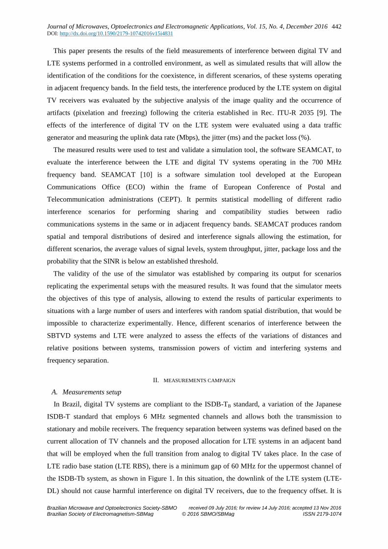
LTE radio base station (LTE RBS), there is a minimum gap of 60 MHz for the uppermost channel of
the ISDB-Tb system, as shown in Figure 1. In this situation, the downlink of the LTE system (LTE-
DL) should not cause harmful interference on digital TV receivers, due to the frequency offset. It is
Journal of Microwaves, Optoelectronics and Electromagnetic Applications, Vol. 15, No. 4, December 2016 DOI: http://dx.doi.org/10.1590/2179-10742016v15i4831
Brazilian Microwave and Optoelectronics Society-SBMO received 09 July 2016; for review 14 July 2016; accepted 13 Nov 2016
Brazilian Society of Electromagnetism-SBMag © 2016 SBMO/SBMag ISSN 2179-1074
443
expected that the main cause of interference will be caused by the LTE uplink (LTE-UL), operating in
the 703 to 748 MHz, on the channels 51 of the digital TV system, as the guard band in this case is
only 5 MHz.
Fig. 1. Spectrum plan for the 700 MHz band
The measurement campaign was carried out in a controlled environment at the laboratory campus
of the National Institute of Metrology (Inmetro) in Xerém, Rio de Janeiro. The technical
characteristics and parameters associated with each technology standards, such as masks, protection
criteria and thresholds were used in the trials. The resulting set of measured results enabled the
evaluation of the interference between systems in simple scenarios and the validation of computer
simulations of more complex scenarios that occur in real situations. The main equipment components
used in the tests are listed in Table I.
TABLE I. EQUIPMENT FOR THE TESTS OF INTERFERENCE BETWEEN LTE AND DIGITAL TV
Equipment Model Manufacturer
Digital TV signal generator SFU Broadcast Test System Rohde&Schwarz
RF Amplifier 5 W TV Exciter UHF/VHF Band DB Elettronica Telecomunicazioni S.p.A.
Panel antenna APO8 DB Digital Broadcast
Digital TV receiver TS2400 Telesystem
Digital LCD TV Bravia Sony
Vehicular antenna CE1549L Celta Telecomunicações
Portable spectrum analyser FSH18 Rohde&Schwarz
LTE station eNodeB Nokia Solutions and Networks (NSN)
Panel antenna APX75-864014-CT0 RFS
Android User terminal Prototype Qualcomm
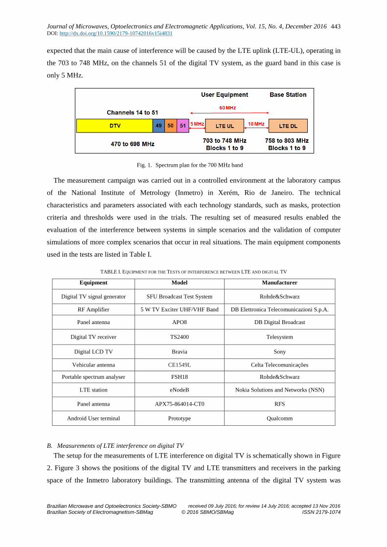
B. Measurements of LTE interference on digital TV
The setup for the measurements of LTE interference on digital TV is schematically shown in Figure
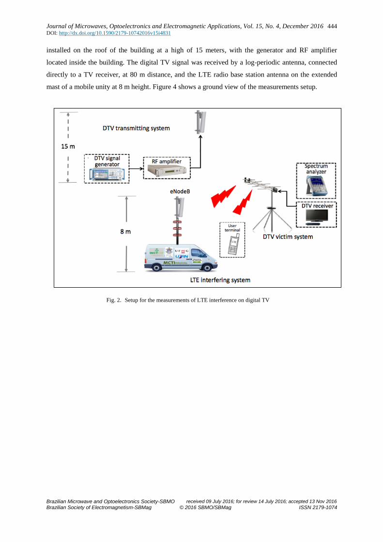
2. Figure 3 shows the positions of the digital TV and LTE transmitters and receivers in the parking
space of the Inmetro laboratory buildings. The transmitting antenna of the digital TV system was
Journal of Microwaves, Optoelectronics and Electromagnetic Applications, Vol. 15, No. 4, December 2016 DOI: http://dx.doi.org/10.1590/2179-10742016v15i4831
Brazilian Microwave and Optoelectronics Society-SBMO received 09 July 2016; for review 14 July 2016; accepted 13 Nov 2016
Brazilian Society of Electromagnetism-SBMag © 2016 SBMO/SBMag ISSN 2179-1074
444
installed on the roof of the building at a high of 15 meters, with the generator and RF amplifier
located inside the building. The digital TV signal was received by a log-periodic antenna, connected
directly to a TV receiver, at 80 m distance, and the LTE radio base station antenna on the extended
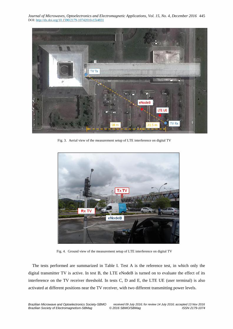
mast of a mobile unity at 8 m height. Figure 4 shows a ground view of the measurements setup.
Fig. 2. Setup for the measurements of LTE interference on digital TV
Journal of Microwaves, Optoelectronics and Electromagnetic Applications, Vol. 15, No. 4, December 2016 DOI: http://dx.doi.org/10.1590/2179-10742016v15i4831
Brazilian Microwave and Optoelectronics Society-SBMO received 09 July 2016; for review 14 July 2016; accepted 13 Nov 2016
Brazilian Society of Electromagnetism-SBMag © 2016 SBMO/SBMag ISSN 2179-1074
445
Fig. 3. Aerial view of the measurement setup of LTE interference on digital TV
Fig. 4. Ground view of the measurement setup of LTE interference on digital TV
The tests performed are summarized in Table I. Test A is the reference test, in which only the
digital transmitter TV is active. In test B, the LTE eNodeB is turned on to evaluate the effect of its
interference on the TV receiver threshold. In tests C, D and E, the LTE UE (user terminal) is also
activated at different positions near the TV receiver, with two different transmitting power levels.
Journal of Microwaves, Optoelectronics and Electromagnetic Applications, Vol. 15, No. 4, December 2016 DOI: http://dx.doi.org/10.1590/2179-10742016v15i4831
Brazilian Microwave and Optoelectronics Society-SBMO received 09 July 2016; for review 14 July 2016; accepted 13 Nov 2016
Brazilian Society of Electromagnetism-SBMag © 2016 SBMO/SBMag ISSN 2179-1074
446
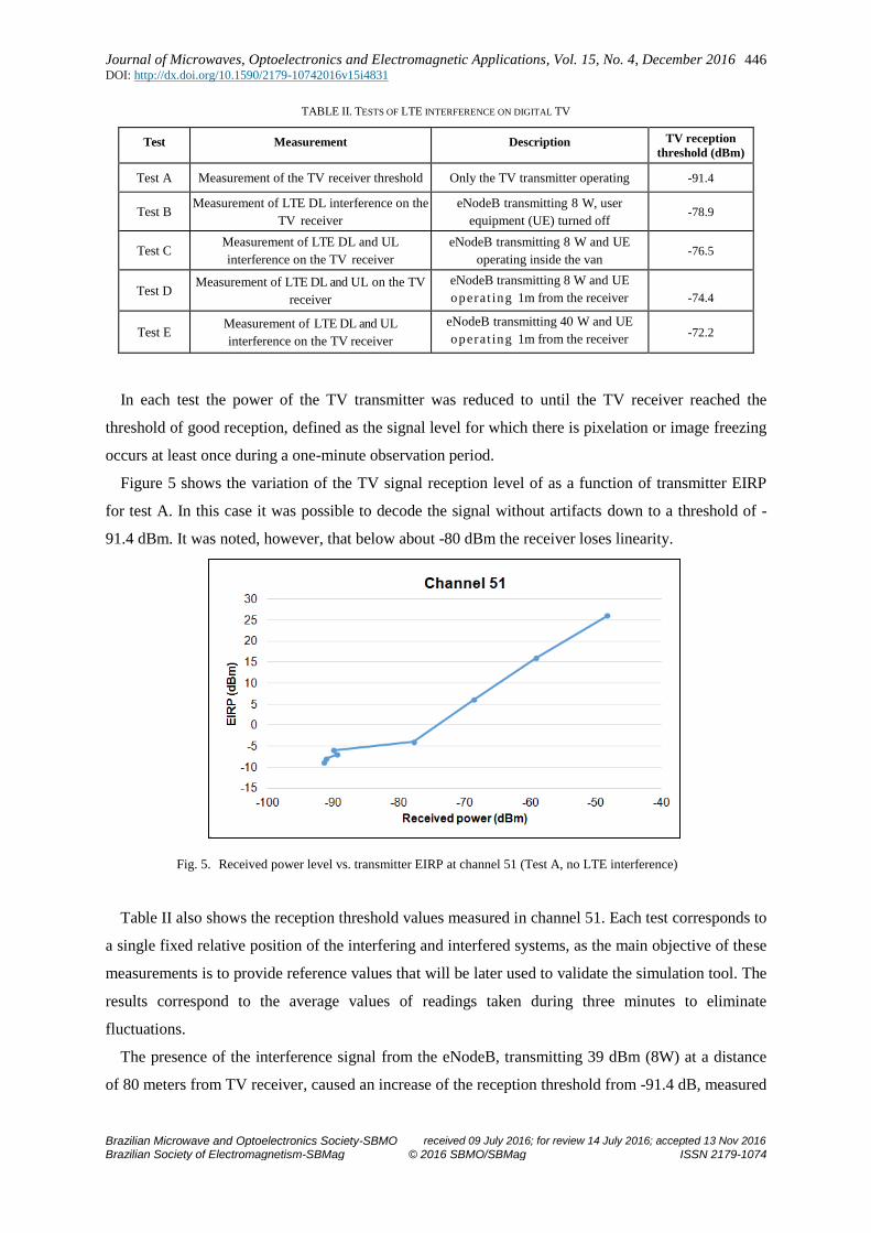
TABLE II. TESTS OF LTE INTERFERENCE ON DIGITAL TV
Test Measurement Description TV reception
threshold (dBm)
Test A Measurement of the TV receiver threshold Only the TV transmitter operating -91.4
Test B Measurement of LTE DL interference on the
TV receiver
eNodeB transmitting 8 W, user
equipment (UE) turned off -78.9
Test C Measurement of LTE DL and UL
interference on the TV receiver
eNodeB transmitting 8 W and UE
operating inside the van -76.5
Test D Measurement of LTE DL and UL on the TV
receiver
eNodeB transmitting 8 W and UE
operat ing 1m from the receiver
antenna
-74.4
Test E Measurement of LTE DL and UL
interference on the TV receiver
eNodeB transmitting 40 W and UE
operat ing 1m from the receiver
antenna
-72.2
In each test the power of the TV transmitter was reduced to until the TV receiver reached the
threshold of good reception, defined as the signal level for which there is pixelation or image freezing
occurs at least once during a one-minute observation period.
Figure 5 shows the variation of the TV signal reception level of as a function of transmitter EIRP
for test A. In this case it was possible to decode the signal without artifacts down to a threshold of -
91.4 dBm. It was noted, however, that below about -80 dBm the receiver loses linearity.
Fig. 5. Received power level vs. transmitter EIRP at channel 51 (Test A, no LTE interference)
Table II also shows the reception threshold values measured in channel 51. Each test corresponds to
a single fixed relative position of the interfering and interfered systems, as the main objective of these
measurements is to provide reference values that will be later used to validate the simulation tool. The
results correspond to the average values of readings taken during three minutes to eliminate
fluctuations.
The presence of the interference signal from the eNodeB, transmitting 39 dBm (8W) at a distance
of 80 meters from TV receiver, caused an increase of the reception threshold from -91.4 dB, measured
Journal of Microwaves, Optoelectronics and Electromagnetic Applications, Vol. 15, No. 4, December 2016 DOI: http://dx.doi.org/10.1590/2179-10742016v15i4831
Brazilian Microwave and Optoelectronics Society-SBMO received 09 July 2016; for review 14 July 2016; accepted 13 Nov 2016
Brazilian Society of Electromagnetism-SBMag © 2016 SBMO/SBMag ISSN 2179-1074
447
in test A, to -78.9 dBm, measured in test B. In tests C, D and E, additional interference was caused by
the LTE UE and the reception threshold varied depending on the UE transmission power and position
of the UE relative to the TV receiver. In the worst case, with the eNodeB transmitting its full power of
46 dBm (40W) at one meter from the TV receiver, the combined interference of the eNodeB and the
UE raised the channel 51 TV reception threshold to -72.2 dBm. No significant degradation of the
reception threshold was observed in channels 49 and 50 in any of the trials.
C. Measurements of digital TV interference on the LTE system
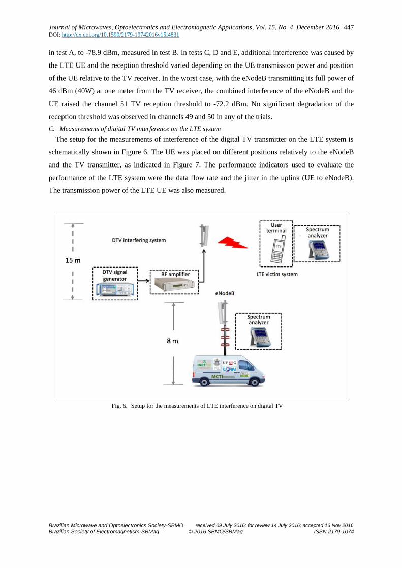
The setup for the measurements of interference of the digital TV transmitter on the LTE system is
schematically shown in Figure 6. The UE was placed on different positions relatively to the eNodeB
and the TV transmitter, as indicated in Figure 7. The performance indicators used to evaluate the
performance of the LTE system were the data flow rate and the jitter in the uplink (UE to eNodeB).
The transmission power of the LTE UE was also measured.
Fig. 6. Setup for the measurements of LTE interference on digital TV
Journal of Microwaves, Optoelectronics and Electromagnetic Applications, Vol. 15, No. 4, December 2016 DOI: http://dx.doi.org/10.1590/2179-10742016v15i4831
Brazilian Microwave and Optoelectronics Society-SBMO received 09 July 2016; for review 14 July 2016; accepted 13 Nov 2016
Brazilian Society of Electromagnetism-SBMag © 2016 SBMO/SBMag ISSN 2179-1074
448
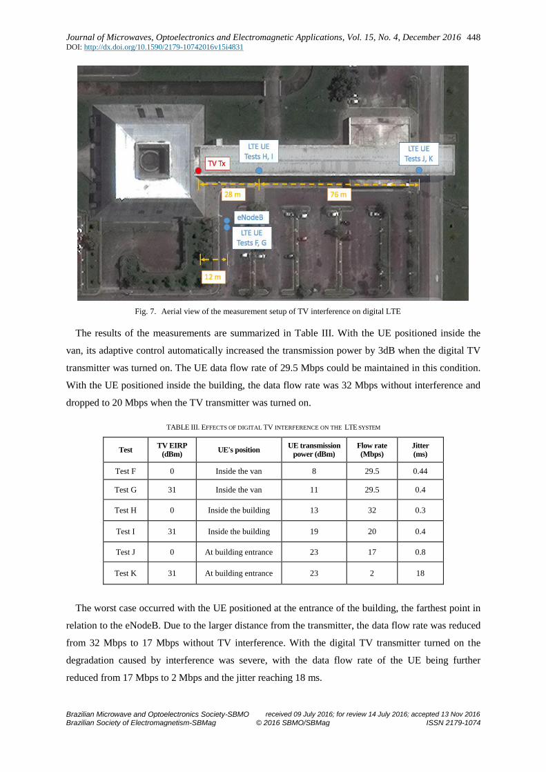
Fig. 7. Aerial view of the measurement setup of TV interference on digital LTE
The results of the measurements are summarized in Table III. With the UE positioned inside the
van, its adaptive control automatically increased the transmission power by 3dB when the digital TV
transmitter was turned on. The UE data flow rate of 29.5 Mbps could be maintained in this condition.
With the UE positioned inside the building, the data flow rate was 32 Mbps without interference and
dropped to 20 Mbps when the TV transmitter was turned on.
TABLE III. EFFECTS OF DIGITAL TV INTERFERENCE ON THE LTE SYSTEM
Test TV EIRP
(dBm) UE's position
UE transmission power (dBm)
Flow rate (Mbps)
Jitter (ms)
Test F 0 Inside the van 8 29.5 0.44
Test G 31 Inside the van 11 29.5 0.4
Test H 0 Inside the building 13 32 0.3
Test I 31 Inside the building 19 20 0.4
Test J 0 At building entrance 23 17 0.8
Test K 31 At building entrance 23 2 18
The worst case occurred with the UE positioned at the entrance of the building, the farthest point in
relation to the eNodeB. Due to the larger distance from the transmitter, the data flow rate was reduced
from 32 Mbps to 17 Mbps without TV interference. With the digital TV transmitter turned on the
degradation caused by interference was severe, with the data flow rate of the UE being further
reduced from 17 Mbps to 2 Mbps and the jitter reaching 18 ms.
Journal of Microwaves, Optoelectronics and Electromagnetic Applications, Vol. 15, No. 4, December 2016 DOI: http://dx.doi.org/10.1590/2179-10742016v15i4831
Brazilian Microwave and Optoelectronics Society-SBMO received 09 July 2016; for review 14 July 2016; accepted 13 Nov 2016
Brazilian Society of Electromagnetism-SBMag © 2016 SBMO/SBMag ISSN 2179-1074
449
III. VALIDATION OF THE SIMULATION TOOL
To validate the use of the SEAMCAT software to statistically evaluate the effects of interference
between digital TV and LTE systems, simulation scenarios reproducing the measurements described
in section II were built and the simulated and measured results compared.
A. The SEAMCAT simulation software
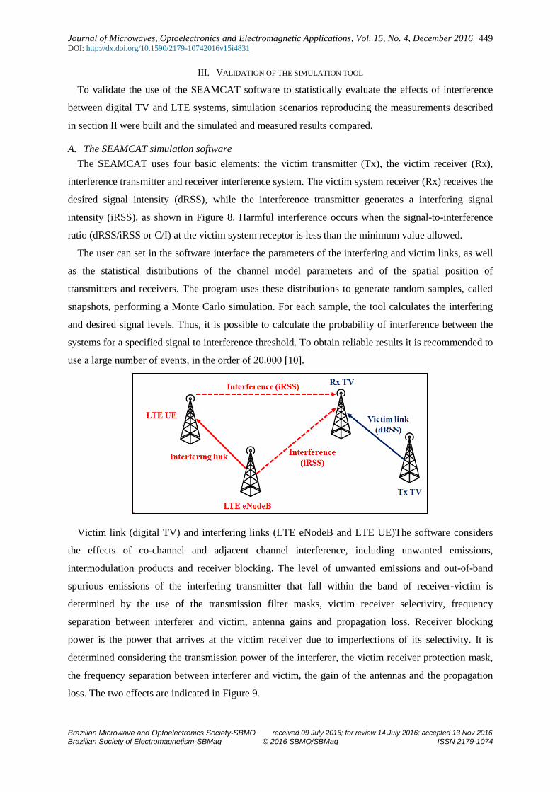
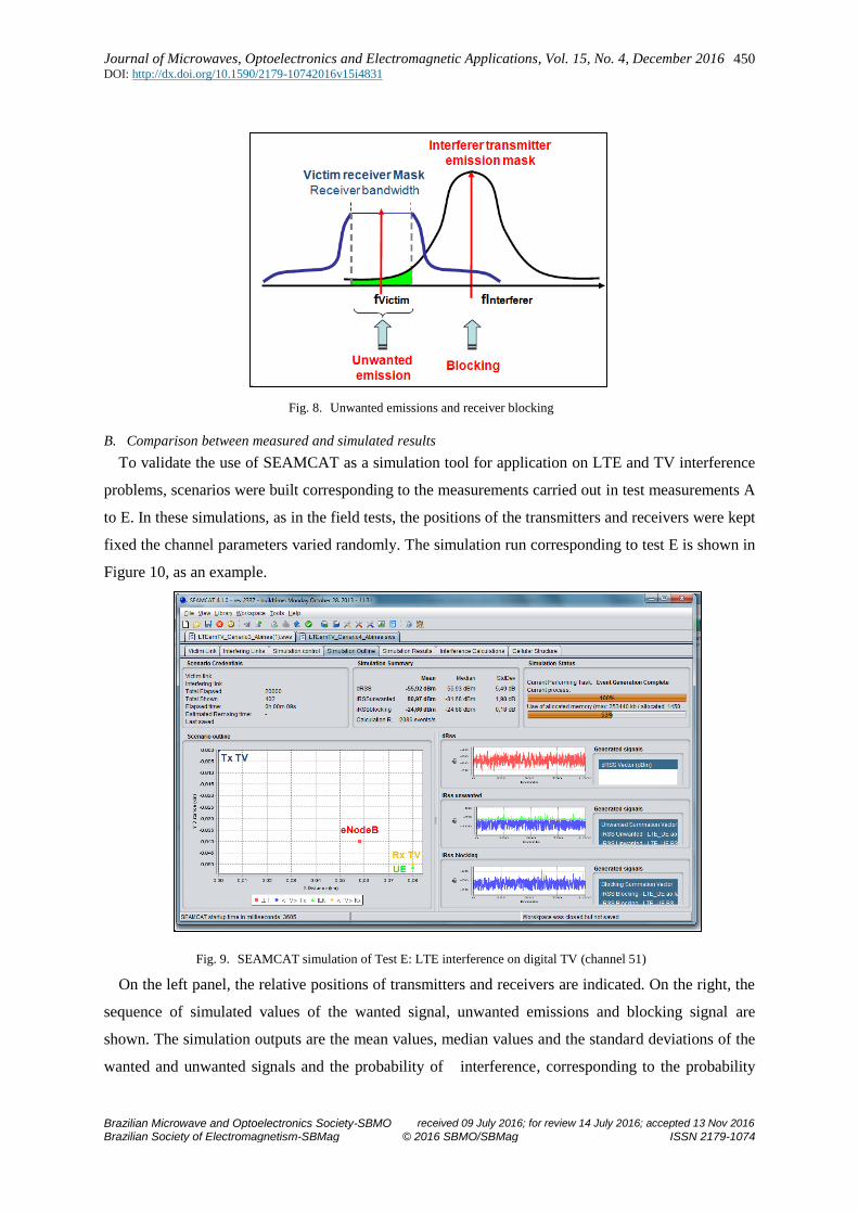
The SEAMCAT uses four basic elements: the victim transmitter (Tx), the victim receiver (Rx),
interference transmitter and receiver interference system. The victim system receiver (Rx) receives the
desired signal intensity (dRSS), while the interference transmitter generates a interfering signal
intensity (iRSS), as shown in Figure 8. Harmful interference occurs when the signal-to-interference
ratio (dRSS/iRSS or C/I) at the victim system receptor is less than the minimum value allowed.
The user can set in the software interface the parameters of the interfering and victim links, as well
as the statistical distributions of the channel model parameters and of the spatial position of
transmitters and receivers. The program uses these distributions to generate random samples, called
snapshots, performing a Monte Carlo simulation. For each sample, the tool calculates the interfering
and desired signal levels. Thus, it is possible to calculate the probability of interference between the
systems for a specified signal to interference threshold. To obtain reliable results it is recommended to
use a large number of events, in the order of 20.000 [10].
Victim link (digital TV) and interfering links (LTE eNodeB and LTE UE)The software considers
the effects of co-channel and adjacent channel interference, including unwanted emissions,
intermodulation products and receiver blocking. The level of unwanted emissions and out-of-band
spurious emissions of the interfering transmitter that fall within the band of receiver-victim is
determined by the use of the transmission filter masks, victim receiver selectivity, frequency
separation between interferer and victim, antenna gains and propagation loss. Receiver blocking
power is the power that arrives at the victim receiver due to imperfections of its selectivity. It is
determined considering the transmission power of the interferer, the victim receiver protection mask,
the frequency separation between interferer and victim, the gain of the antennas and the propagation
loss. The two effects are indicated in Figure 9.
Journal of Microwaves, Optoelectronics and Electromagnetic Applications, Vol. 15, No. 4, December 2016 DOI: http://dx.doi.org/10.1590/2179-10742016v15i4831
Brazilian Microwave and Optoelectronics Society-SBMO received 09 July 2016; for review 14 July 2016; accepted 13 Nov 2016
Brazilian Society of Electromagnetism-SBMag © 2016 SBMO/SBMag ISSN 2179-1074
450
Fig. 8. Unwanted emissions and receiver blocking
B. Comparison between measured and simulated results
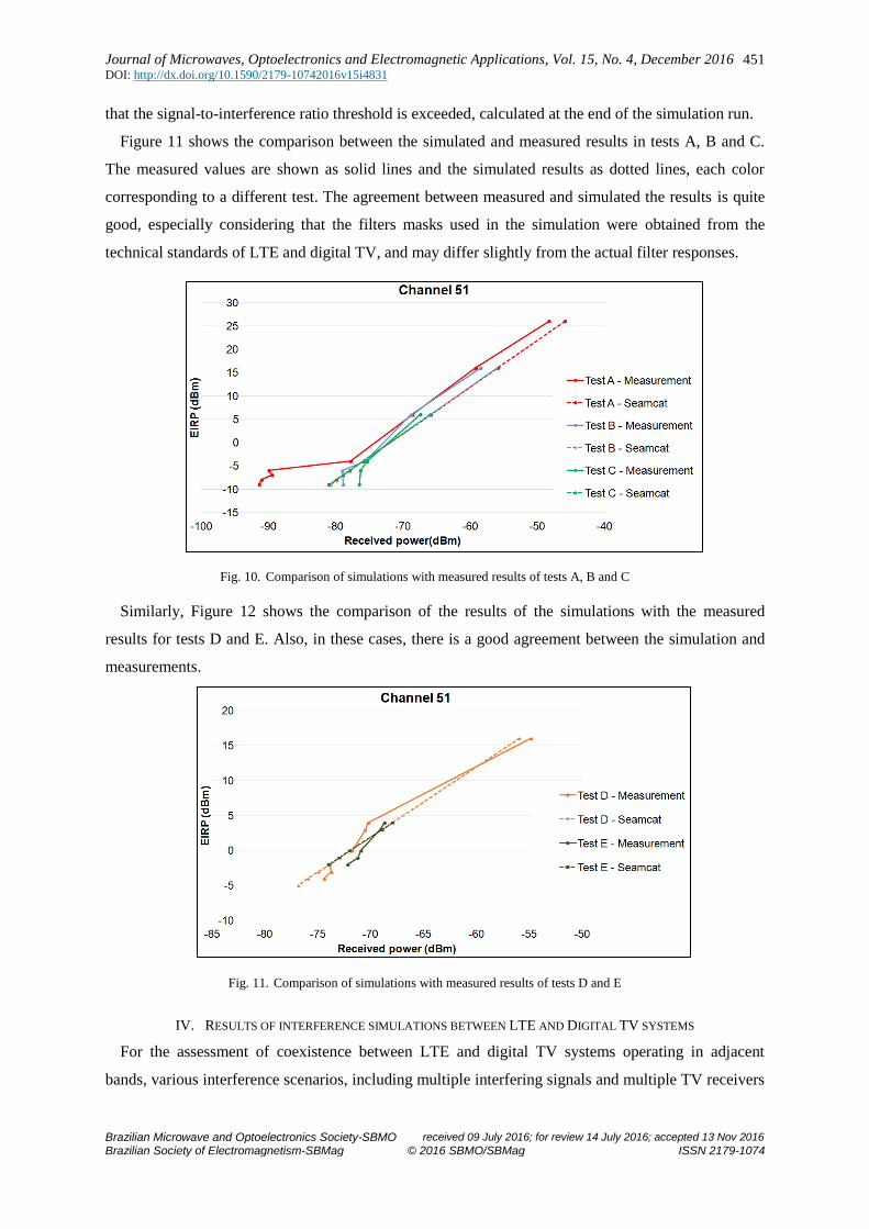
To validate the use of SEAMCAT as a simulation tool for application on LTE and TV interference
problems, scenarios were built corresponding to the measurements carried out in test measurements A
to E. In these simulations, as in the field tests, the positions of the transmitters and receivers were kept
fixed the channel parameters varied randomly. The simulation run corresponding to test E is shown in
Figure 10, as an example.
Fig. 9. SEAMCAT simulation of Test E: LTE interference on digital TV (channel 51)
On the left panel, the relative positions of transmitters and receivers are indicated. On the right, the
sequence of simulated values of the wanted signal, unwanted emissions and blocking signal are
shown. The simulation outputs are the mean values, median values and the standard deviations of the
wanted and unwanted signals and the probability of interference, corresponding to the probability
Journal of Microwaves, Optoelectronics and Electromagnetic Applications, Vol. 15, No. 4, December 2016 DOI: http://dx.doi.org/10.1590/2179-10742016v15i4831
Brazilian Microwave and Optoelectronics Society-SBMO received 09 July 2016; for review 14 July 2016; accepted 13 Nov 2016
Brazilian Society of Electromagnetism-SBMag © 2016 SBMO/SBMag ISSN 2179-1074
451
that the signal-to-interference ratio threshold is exceeded, calculated at the end of the simulation run.
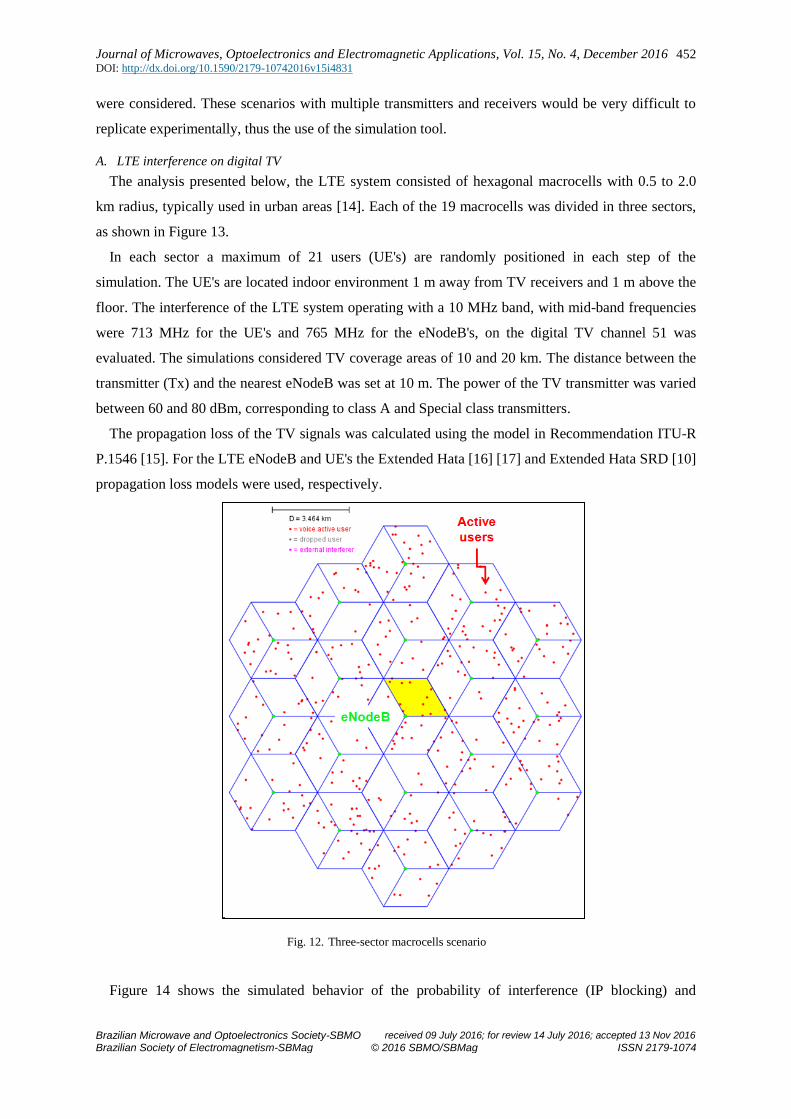
Figure 11 shows the comparison between the simulated and measured results in tests A, B and C.
The measured values are shown as solid lines and the simulated results as dotted lines, each color
corresponding to a different test. The agreement between measured and simulated the results is quite
good, especially considering that the filters masks used in the simulation were obtained from the
technical standards of LTE and digital TV, and may differ slightly from the actual filter responses.
Fig. 10. Comparison of simulations with measured results of tests A, B and C
Similarly, Figure 12 shows the comparison of the results of the simulations with the measured
results for tests D and E. Also, in these cases, there is a good agreement between the simulation and
measurements.
Fig. 11. Comparison of simulations with measured results of tests D and E
IV. RESULTS OF INTERFERENCE SIMULATIONS BETWEEN LTE AND DIGITAL TV SYSTEMS
For the assessment of coexistence between LTE and digital TV systems operating in adjacent
bands, various interference scenarios, including multiple interfering signals and multiple TV receivers
Journal of Microwaves, Optoelectronics and Electromagnetic Applications, Vol. 15, No. 4, December 2016 DOI: http://dx.doi.org/10.1590/2179-10742016v15i4831
Brazilian Microwave and Optoelectronics Society-SBMO received 09 July 2016; for review 14 July 2016; accepted 13 Nov 2016
Brazilian Society of Electromagnetism-SBMag © 2016 SBMO/SBMag ISSN 2179-1074
452
were considered. These scenarios with multiple transmitters and receivers would be very difficult to
replicate experimentally, thus the use of the simulation tool.
A. LTE interference on digital TV
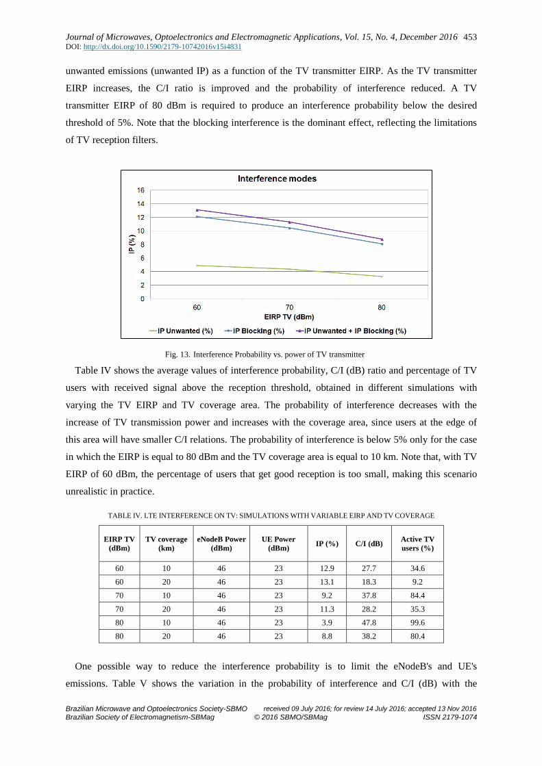
The analysis presented below, the LTE system consisted of hexagonal macrocells with 0.5 to 2.0
km radius, typically used in urban areas [14]. Each of the 19 macrocells was divided in three sectors,
as shown in Figure 13.
In each sector a maximum of 21 users (UE's) are randomly positioned in each step of the
simulation. The UE's are located indoor environment 1 m away from TV receivers and 1 m above the
floor. The interference of the LTE system operating with a 10 MHz band, with mid-band frequencies
were 713 MHz for the UE's and 765 MHz for the eNodeB's, on the digital TV channel 51 was
evaluated. The simulations considered TV coverage areas of 10 and 20 km. The distance between the
transmitter (Tx) and the nearest eNodeB was set at 10 m. The power of the TV transmitter was varied
between 60 and 80 dBm, corresponding to class A and Special class transmitters.
The propagation loss of the TV signals was calculated using the model in Recommendation ITU-R
P.1546 [15]. For the LTE eNodeB and UE's the Extended Hata [16] [17] and Extended Hata SRD [10]
propagation loss models were used, respectively.
Fig. 12. Three-sector macrocells scenario
Figure 14 shows the simulated behavior of the probability of interference (IP blocking) and
Journal of Microwaves, Optoelectronics and Electromagnetic Applications, Vol. 15, No. 4, December 2016 DOI: http://dx.doi.org/10.1590/2179-10742016v15i4831
Brazilian Microwave and Optoelectronics Society-SBMO received 09 July 2016; for review 14 July 2016; accepted 13 Nov 2016
Brazilian Society of Electromagnetism-SBMag © 2016 SBMO/SBMag ISSN 2179-1074
453
unwanted emissions (unwanted IP) as a function of the TV transmitter EIRP. As the TV transmitter
EIRP increases, the C/I ratio is improved and the probability of interference reduced. A TV
transmitter EIRP of 80 dBm is required to produce an interference probability below the desired
threshold of 5%. Note that the blocking interference is the dominant effect, reflecting the limitations
of TV reception filters.
Fig. 13. Interference Probability vs. power of TV transmitter
Table IV shows the average values of interference probability, C/I (dB) ratio and percentage of TV
users with received signal above the reception threshold, obtained in different simulations with
varying the TV EIRP and TV coverage area. The probability of interference decreases with the
increase of TV transmission power and increases with the coverage area, since users at the edge of
this area will have smaller C/I relations. The probability of interference is below 5% only for the case
in which the EIRP is equal to 80 dBm and the TV coverage area is equal to 10 km. Note that, with TV
EIRP of 60 dBm, the percentage of users that get good reception is too small, making this scenario
unrealistic in practice.
TABLE IV. LTE INTERFERENCE ON TV: SIMULATIONS WITH VARIABLE EIRP AND TV COVERAGE
EIRP TV
(dBm)
TV coverage
(km)
eNodeB Power
(dBm)
UE Power
(dBm) IP (%) C/I (dB)
Active TV
users (%)
60 10 46 23 12.9 27.7 34.6
60 20 46 23 13.1 18.3 9.2
70 10 46 23 9.2 37.8 84.4
70 20 46 23 11.3 28.2 35.3
80 10 46 23 3.9 47.8 99.6
80 20 46 23 8.8 38.2 80.4
One possible way to reduce the interference probability is to limit the eNodeB's and UE's
emissions. Table V shows the variation in the probability of interference and C/I (dB) with the
Journal of Microwaves, Optoelectronics and Electromagnetic Applications, Vol. 15, No. 4, December 2016 DOI: http://dx.doi.org/10.1590/2179-10742016v15i4831
Brazilian Microwave and Optoelectronics Society-SBMO received 09 July 2016; for review 14 July 2016; accepted 13 Nov 2016
Brazilian Society of Electromagnetism-SBMag © 2016 SBMO/SBMag ISSN 2179-1074
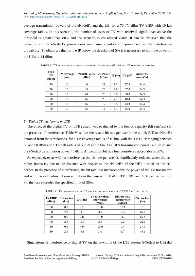
454
average transmission powers of the eNodeB's and the UE, for a 70 TV dBm TV EIRP with 10 km
coverage radius. In this scenario, the number of users of TV with received signal level above the
threshold is greater than 80% and the scenario is considered viable. It can be observed that the
reduction of the eNodeB's power does not cause significant improvement in the interference
probability. To obtain a value for the IP below the threshold of 5% it is necessary to limit the power of
the UE's to 14 dBm.
TABLE V. LTE INTERFERENCE SIMULATIONS WITH LIMITATION OF ENODEB AND UE TRANSMISSION POWER
EIRP
TV
(dBm)
TV coverage
(km)
eNodeB Power
(dBm)
UE Power
(dBm) IP (%) C/I (dB)
Active TV
users (%)
70 10 46 23 9.2 37.8 84.4
70 10 43 23 9.0 37.9 84.3
70 10 40 23 8.9 38.0 84.3
70 10 46 20 7.1 40.4 84.3
70 10 46 17 5.5 43.3 84.4
70 10 46 14 4.7 45.8 84.4
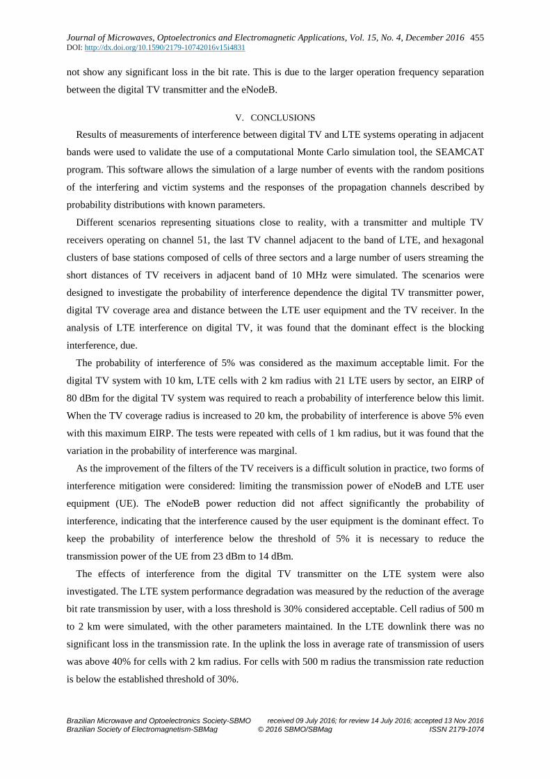
B. Digital TV interference on LTE
The effect of the digital TV on LTE system was evaluated by the loss of capacity (bit rate/user) in
the presence of interference. Table VI shows the results bit rate per user in the uplink (UE to eNodeB)
obtained from the simulations, for a TV coverage radius of 10 km, with the TV EIRP ranging between
60 and 80 dBm and LTE cell radius of 500 m and 2 km. The UE's transmission power is 23 dBm and
the eNodeB transmission power 46 dBm. A maximum bit rate loss considered acceptable is 30%.
As expected, even without interference the bit rate per user is significantly reduced when the cell
radius increases, due to the distance with respect to the eNodeB's of the UE's located on the cell
border. In the presence of interference, the bit rate loss increases with the power of the TV transmitter
and with the cell radius. However, only in the case with 80 dBm TV EIRP and LTE cell radius of 2
km the loss exceeded the specified limit of 30%.
TABLE VI. TV INTERFERENCE ON LTE SIMULATIONS WITH VARIABLE TV EIRP AND CELL RADIUS
TV EIRP
(dBm)
Cell radius
(km) C/I (dB)
Bit rate without
interference
(Mbps)
Bit rate with
interference
(Mbps)
Bit rate loss
(%)
60 0.5 8.2 13.0 12.1 6.8
60 2.0 -3.5 3.0 2.5 16.0
70 0.5 6.8 13.0 11.0 15.3
70 2.0 -5.8 3.0 2.2 28.6
80 0.5 4.0 13.0 9.4 27.9
80 2.0 -9.5 3.0 1.7 45.1
Simulations of interference of digital TV on the downlink of the LTE system (eNodeB to UE) did
Journal of Microwaves, Optoelectronics and Electromagnetic Applications, Vol. 15, No. 4, December 2016 DOI: http://dx.doi.org/10.1590/2179-10742016v15i4831
Brazilian Microwave and Optoelectronics Society-SBMO received 09 July 2016; for review 14 July 2016; accepted 13 Nov 2016
Brazilian Society of Electromagnetism-SBMag © 2016 SBMO/SBMag ISSN 2179-1074
455
not show any significant loss in the bit rate. This is due to the larger operation frequency separation
between the digital TV transmitter and the eNodeB.
V. CONCLUSIONS
Results of measurements of interference between digital TV and LTE systems operating in adjacent
bands were used to validate the use of a computational Monte Carlo simulation tool, the SEAMCAT
program. This software allows the simulation of a large number of events with the random positions
of the interfering and victim systems and the responses of the propagation channels described by
probability distributions with known parameters.
Different scenarios representing situations close to reality, with a transmitter and multiple TV
receivers operating on channel 51, the last TV channel adjacent to the band of LTE, and hexagonal
clusters of base stations composed of cells of three sectors and a large number of users streaming the
short distances of TV receivers in adjacent band of 10 MHz were simulated. The scenarios were
designed to investigate the probability of interference dependence the digital TV transmitter power,
digital TV coverage area and distance between the LTE user equipment and the TV receiver. In the
analysis of LTE interference on digital TV, it was found that the dominant effect is the blocking
interference, due.
The probability of interference of 5% was considered as the maximum acceptable limit. For the
digital TV system with 10 km, LTE cells with 2 km radius with 21 LTE users by sector, an EIRP of
80 dBm for the digital TV system was required to reach a probability of interference below this limit.
When the TV coverage radius is increased to 20 km, the probability of interference is above 5% even
with this maximum EIRP. The tests were repeated with cells of 1 km radius, but it was found that the
variation in the probability of interference was marginal.
As the improvement of the filters of the TV receivers is a difficult solution in practice, two forms of
interference mitigation were considered: limiting the transmission power of eNodeB and LTE user
equipment (UE). The eNodeB power reduction did not affect significantly the probability of
interference, indicating that the interference caused by the user equipment is the dominant effect. To
keep the probability of interference below the threshold of 5% it is necessary to reduce the
transmission power of the UE from 23 dBm to 14 dBm.
The effects of interference from the digital TV transmitter on the LTE system were also
investigated. The LTE system performance degradation was measured by the reduction of the average
bit rate transmission by user, with a loss threshold is 30% considered acceptable. Cell radius of 500 m
to 2 km were simulated, with the other parameters maintained. In the LTE downlink there was no
significant loss in the transmission rate. In the uplink the loss in average rate of transmission of users
was above 40% for cells with 2 km radius. For cells with 500 m radius the transmission rate reduction
is below the established threshold of 30%.
Journal of Microwaves, Optoelectronics and Electromagnetic Applications, Vol. 15, No. 4, December 2016 DOI: http://dx.doi.org/10.1590/2179-10742016v15i4831
Brazilian Microwave and Optoelectronics Society-SBMO received 09 July 2016; for review 14 July 2016; accepted 13 Nov 2016
Brazilian Society of Electromagnetism-SBMag © 2016 SBMO/SBMag ISSN 2179-1074
456
ACKNOWLEDGMENT
This work was supported by the National Institute Metrology, Quality and Technology, Inmetro,
under the Pronametro and Prometro Programs, and by CNPq (National Research Council, Brazil),
under covenant 573939/2008-0 (INCT-CSF).
REFERENCES
[1] Cho, In-kyoung; Lee, Il-kyoo; Park, Youn-ok, "Study on coexistence between long term evolution and digital broadcasting services," International Journal of Advanced Science and Technology, vol. 38, pp. 75-92, January 2012.
[2] National Telecommunications Agency-ANATEL, "Laboratory test report of interference of LTE in 700 MHz band in ISDB-T," 2014. [Online]. Available: http://www.anatel.gov.br. [Access in March 26, 2015].
[3] National Telecommunications Agency-ANATEL, "field test Report about the Coexistence of LTE in 700 MHz band with ISDB-T," April 2014. [Online]. Available: http://www.anatel.gov.br. [Access in March 26, 2015].
[4] Universidade Presbiteriana Mackenzie, "Report of the trials of LTE signal interference on digital TV on UHF band," November 2013. [Online]. Available: http://www.set.org.br/tecnologia/RELATÓRIO MACKENZIE LTE.pdf TESTS. [Access in March 26, 2015].
[5] SET, "LTE signal interference tests on digital TV reception on UHF band," February 2014. [Online]. Available: http://www.set.org.br/tecnologia/SET-test result of interferência_do_4G_LTE _ _10.02.2014.pdf. [Access in March 26, 2015].
[6] Mathe, D.M., " Interference Analysis between Digital Television and LTE System under Adjacent Channels in the 700 MHz Band”. International Journal of Information Technology & Computer Science (IJITCS), v. 13, p. 42-50, 2014.
[7] Grant, Paul, "Report for GSMA on the Coexistence of ISDB-T and LTE," 29 November 2013. [Online]. Available: http://www.gsma.com/spectrum/wp- content/uploads//01/2014 ATDI. Report-on-LTE-and-ISDB-T-coexistence-study-Issue-1. -2013.pdf. [accessed March 26, 2015].
[8] Kim, Dae-Hee; Oh, Seong-Jun; Woo, JungSoo, "Coexistence Analysis between IMT System and DTV System in the 700 MHz Band," International Conference on ICT Convergence (ICTC), pp. 284-288, October 2012.
[9] International Telecommunication Union-ITU, "Report ITU-R BT. 2035-1: Guidelines and techniques for the evaluation of digital terrestrial television broadcasting systems," Geneva, Switzerland, 2004.
[10] European Communications Office-ECO, "SEAMCAT Handbook," January 2010. [Online]. Available: http://www.cept.org/files/1050/documents/SEAMCAT Handbook January 2010.pdf. [Access in March 24, 2015].
[11] Okamoto, Danielle Mendonça, "Analysis of coexistence between digital TV and LTE in 700 MHz band – measures and simulations," Thesis (Ph. D. in electrical engineering), graduate program in electrical engineering, PUC-Rio, April 2016.
[12] C. Rodriguez, D. Okamoto and M. Pudwell, "coexistence testing project between the Brazilian digital television system and LTE in 700 MHz band (band 28 3GPP). Activity 3: field tests conducted on the campus of INMETRO in Xerém, RIO DE JANEIRO and with commercial network in Aparecida, SP, 2014 ". [Online]. Available: http://www.abinee.org.br/informac/arquivos/relmed.pdf. [Access in March 24, 2015].
[13] Keys, Fabiano de Sousa; Ruismaki, Rauno, "700 MHz LTE: Evaluation of the Probability of Interference to Digital TV," Vehicular Technology Conference (VTC Fall), 2014 IEEE 80th, pp. 1-7, 14-17 September 2014.
[14] ZTE Corporation, "APT 700 MHz: Best Choice for nationwide coverage," June 2013. [Online]. Available: http://www.gsma.com/spectrum/wp- content/uploads/2013/07/ZTE-LTE-APT-700MHz-Network-White-Paper-ZTE-June-2013.pdf. [February 22, 2016 access].
[15] International Telecommunication Union (ITU), "Recommendation ITU-R p. 1546-5: Method for point-to-area predictions for terrestrial services in the frequency range 30 MHz to 3000 MHz," Geneva, 2013.
[16] Y. Okumura, "Field strength and its variability in VHF and UHF land-mobile radio services," Review of the Electrical Communications Laboratory, vol. 16, September-October 1968.
[17] M. Hata, "Empirical formula for propagation loss in land mobile radio services," IEEE Transactions on Vehicular Technology, vol. vol. VT-29, pp. 317-325, September 1981.