Embed Size (px)
Citation preview
Performance and Energy Efficiency via
an Adaptive MorphCore Architecture
Khubaib
High Performance Systems GroupDepartment of Electrical and Computer Engineering
The University of Texas at Austin
Austin, Texas 78712-0240
TR-HPS-2014-002
July 2014

This page is intentionally left blank.

Copyright
by
Khubaib
2014

The Dissertation Committee for Khubaib
certifies that this is the approved version of the following dissertation:
Performance and Energy Efficiency via
an Adaptive MorphCore Architecture
Committee:
Yale N. Patt, Supervisor
Derek Chiou
Mattan Erez
Keshav Pingali
Chris Wilkerson

Performance and Energy Efficiency via
an Adaptive MorphCore Architecture
by
Khubaib, B.S.E.E.; M.S.E.
DISSERTATION
Presented to the Faculty of the Graduate School of
The University of Texas at Austin
in Partial Fulfillment
of the Requirements
for the Degree of
DOCTOR OF PHILOSOPHY
THE UNIVERSITY OF TEXAS AT AUSTIN
May 2014

Dedicated to my mother, Ammi Jaan

Acknowledgments
First and foremost, I thank my advisor, Professor Yale N. Patt. I learned
the fundamentals of computer architecture and microprocessor design in his 360N
and 382N classes. His emphasis on fundamentals has always been inspirational to
me. Professor Patt created a great environment for learning and doing impactful
research. His feedback on my thesis and on all my other research projects has
strengthened my work. He taught me a lot about communicating effectively via
writing and presentations. I thank him for training me as a computer architect as
well as teaching me many valuable real-life lessons. Lastly, I thank him for taking
good care of his students.
I thank Aater Suleman for being a great friend and mentor, for helping me
in writing papers, and for his many technical contributions to my research. He has
shown me the value of creating and quickly evaluating first-order insights. Aater
introduced me to the world of heterogeneous computing from which the idea of
MorphCore came about. Additionally, I have benefited from simulation infrastruc-
ture that he developed. I am thankful to him for always being there to listen to my
problems and to help me, in matters related to both research and life in general.
I thank the members of the HPS research group that worked with me while
I was in the group: Peter Kim, Jose Joao, Chang Joo Lee, Eiman Ebrahimi, Rustam
Miftakhutdinov, Veynu Narasiman, Carlos Villavieja, Marco A. Z. Alves, Milad
Hashemi, Faruk Guvenilir, and Ben (Ching-Pei) Lin. They have been great friends
and colleagues. The interactions with them have improved my research and have
helped me develop as a computer architect. I thank Jose for always being there
to answer any question I have, for maintaining our group’s infrastructure, and for
helping me with my papers. I thank Chang Joo for helping me with my questions
on the memory system and I thank Rustam for providing insightful critique on my
ideas, and for helping me with my simulation infrastructure. I thank Milad for
vii

his candid feedback on my ideas and for his many contributions to MorphCore
research and paper. I thank Eiman, Veynu, Carlos, Marco, Faruk, and Ben for
useful feedback on my research, for helping me in writing, and for teaching me
computer architecture. I also thank them for proofreading my thesis. The best thing
about being in the HPS research group with all of these people was the feeling that
I can go talk to any one of them anytime about anything, and afterwards I would
be happy that I did. Besides the HPS group members, I would like to express my
gratitude to the following people and organizations.
I thank the members of my committee, Professor Derek Chiou, Professor
Mattan Erez, Professor Keshav Pingali, and Chris Wilkerson for providing useful
feedback.
I thank Nikhil Patil for always challenging my ideas, providing insightful
feedback, reading my drafts, and for being a great friend. I have always learned
something new after talking to him. I thank Moinuddin Qureshi for improving my
understanding of caching and the memory system. I also thank him and Viji Srini-
vasan for mentoring me during my internship at IBM. I thank Rob Chappell, Chris
Wilkerson, Doug Carmean, and Jared Stark for mentoring me during my internships
at Intel and for useful discussions on research. Chris provided insightful feedback
on many ideas that I explored during my work on MorphCore. I thank Onur Mutlu
for useful discussions on research and for always pushing me to do more. I thank
Francis Tseng, Bharath Balasubramanian, Chris Fallin, Dimitris Prountzos, George
(Chia-Chih) Chen, and Hari Angepat for their friendship and useful discussions. I
thank Dr. Shoab A. Khan for being a role model when I was going through my
undergraduate education and for always being extremely helpful.
I thank Leticia Lira for her outstanding administrative support to HPS re-
search group, Melanie Gulick for helping with matters related to ECE department
and paperwork, and Intel for providing me with a PhD Fellowship.
My life in Austin and at UT would not have been good without the good
company of my friends: Owais Khan, Zubair Malik, Umar Farooq, Amber Hassaan,
viii

Faisal Iqbal, Tauseef Rab and Rashid Kaleem. I have enjoyed many nights and
dinners with them discussing all sorts of random things. I especially thank my
longtime roommate, Owais, for his great company. I thank my friends Bilal Amin,
Shahzad Yasin, Bilal Saqib, and Imran Bhai for all the wonderful time we had
together in Pakistan. These memories have kept me going during the tough times
in graduate school.
Finally, I would like to thank my family. This thesis is dedicated to my
mother. Without her infinite love, support, and confidence I would not have come
to graduate school and finished my PhD. She has taught me the value of education,
hard work and perseverance. I owe all my successes to her, and no words could
express my gratitude to her. I am greatly thankful to my sisters, Ayesha and Fatima,
for continuous love and support, and to my brother, Ubaid, who took care of matters
at home while I was away. I would like to thank my wife, Sana, for her love and
support during the last one and a half years of my PhD, and for pushing me to
defend. I have been fortunate to have her in my life. Today I would also like to pay
tribute to the memory of my late father. He would have been very happy to see me
completing my formal education. The values he taught me at very young age have
made me who I am today. My family has been a source of great comfort for me,
and this thesis would be meaningless without them.
Khubaib
May 2014, Austin, TX
ix
Performance and Energy Efficiency via
an Adaptive MorphCore Architecture
Khubaib, Ph.D.
The University of Texas at Austin, 2014
Supervisor: Yale N. Patt
The level of Thread-Level Parallelism (TLP), Instruction-Level Parallelism
(ILP), and Memory-Level Parallelism (MLP) varies across programs and across
program phases. Hence, every program requires different underlying core microar-
chitecture resources for high performance and/or energy efficiency. Current core
microarchitectures are inefficient because they are fixed at design time and do not
adapt to variable TLP, ILP, or MLP.
I show that if a core microarchitecture can adapt to the variation in TLP,
ILP, and MLP, significantly higher performance and/or energy efficiency can be
achieved. I propose MorphCore, a low-overhead adaptive microarchitecture built
from a traditional OOO core with small changes. MorphCore adapts to TLP by
operating in two modes: (a) as a wide-width large-OOO-window core when TLP is
low and ILP is high, and (b) as a high-performance low-energy highly-threaded in-
order SMT core when TLP is high. MorphCore adapts to ILP and MLP by varying
the superscalar width and the out-of-order (OOO) window size by operating in four
x

modes: (1) as a wide-width large-OOO-window core, 2) as a wide-width medium-
OOO-window core, 3) as a medium-width large-OOO-window core, and 4) as a
medium-width medium-OOO-window core.
My evaluation with single-thread and multi-thread benchmarks shows that
when highest single-thread performance is desired, MorphCore achieves perfor-
mance similar to a traditional out-of-order core. When energy efficiency is desired
on single-thread programs, MorphCore reduces energy by up to 15% (on average
8%) over an out-of-order core. When high multi-thread performance is desired,
MorphCore increases performance by 21% and reduces energy consumption by
20% over an out-of-order core. Thus, for multi-thread programs, MorphCore’s en-
ergy efficiency is similar to highly-threaded throughput-optimized small and medium
core architectures, and its performance is two-thirds of their potential.
xi
Table of Contents
Acknowledgments vii
Abstract x
List of Tables xvi
List of Figures xvii
Chapter 1. Introduction 1
1.1 The Problem . . . . . . . . . . . . . . . . . . . . . . . . . . . . . . 1
1.2 The Solution . . . . . . . . . . . . . . . . . . . . . . . . . . . . . . 3
1.3 Thesis Statement . . . . . . . . . . . . . . . . . . . . . . . . . . . . 4
1.4 Contributions . . . . . . . . . . . . . . . . . . . . . . . . . . . . . 4
1.5 Dissertation Organization . . . . . . . . . . . . . . . . . . . . . . . 5
Chapter 2. Overview of MorphCore Architecture 6
2.1 Baseline Large OOO Core . . . . . . . . . . . . . . . . . . . . . . . 6
2.1.1 Energy Cost of OOO Execution . . . . . . . . . . . . . . . . 7
2.2 Adapting to TLP . . . . . . . . . . . . . . . . . . . . . . . . . . . . 8
2.2.1 The Potential of In-Order SMT . . . . . . . . . . . . . . . . 8
2.2.2 Repurposing Core’s Resources . . . . . . . . . . . . . . . . . 10
2.2.3 Operating Modes . . . . . . . . . . . . . . . . . . . . . . . . 10
2.3 Adapting to ILP and MLP . . . . . . . . . . . . . . . . . . . . . . . 10
2.3.1 Energy Cost of Wide Width . . . . . . . . . . . . . . . . . . 11
2.3.2 Problem: Different Programs Benefit Differently from WideWidth and/or Large OOO Window . . . . . . . . . . . . . . 12
2.3.3 Our Solution: Dynamically Vary Width and Window Size . . 14
Chapter 3. Adapting to Thread-Level Parallelism (TLP) 16
3.1 MorphCore Microarchitecture . . . . . . . . . . . . . . . . . . . . . 16
3.1.1 Overview . . . . . . . . . . . . . . . . . . . . . . . . . . . . 16
3.1.2 Fetch and Decode Stages. . . . . . . . . . . . . . . . . . . . 17
3.1.3 Rename Stage . . . . . . . . . . . . . . . . . . . . . . . . . 17
xii
3.1.4 Select and Wakeup . . . . . . . . . . . . . . . . . . . . . . . 20
3.1.5 Execution and Commit . . . . . . . . . . . . . . . . . . . . . 22
3.1.6 Load/Store Unit . . . . . . . . . . . . . . . . . . . . . . . . 22
3.1.7 Recovering from Branch Mispredictions . . . . . . . . . . . 23
3.2 MorphCore Discussion . . . . . . . . . . . . . . . . . . . . . . . . 24
3.2.1 Area and Power Overhead of MorphCore . . . . . . . . . . . 24
3.2.2 Timing/Frequency Impact of MorphCore . . . . . . . . . . . 24
3.2.3 Turning Off Structures in InOrder Mode . . . . . . . . . . . 25
3.2.4 Interaction with OS . . . . . . . . . . . . . . . . . . . . . . 25
Chapter 4. Mode Switching Policy for Adapting to TLP and Evaluation 26
4.1 When to Operate in OutofOrder Mode or in InOrder Mode? . . . . . 26
4.1.1 Changing Mode from OutofOrder to InOrder . . . . . . . . . 27
4.1.2 Changing Mode from InOrder to OutofOrder . . . . . . . . . 27
4.1.3 Overhead of Changing the Mode . . . . . . . . . . . . . . . 28
4.1.4 Handling Medium TLP . . . . . . . . . . . . . . . . . . . . 29
4.2 Experimental Methodology . . . . . . . . . . . . . . . . . . . . . . 29
4.2.1 Workloads . . . . . . . . . . . . . . . . . . . . . . . . . . . 31
4.3 Results . . . . . . . . . . . . . . . . . . . . . . . . . . . . . . . . . 33
4.3.1 Single-Thread Results . . . . . . . . . . . . . . . . . . . . . 34
4.3.2 Multi-Thread Results . . . . . . . . . . . . . . . . . . . . . . 37
4.3.3 Single-thread and Multi-thread Results Summary . . . . . . . 41
4.3.4 Sensitivity of MorphCore’s Results to Frequency Penalty . . . 41
4.3.5 Comparison with an 8-way SMT OOO Core . . . . . . . . . 42
4.3.6 Effect of a Limited Capacity/Bandwidth Memory System . . 47
4.3.7 Effect of Increasing the Superscalar Width . . . . . . . . . . 50
Chapter 5. Adapting to Instruction-Level Parallelism (ILP) and Memory-Level Parallelism (MLP) 52
5.1 InOrder Mode for Single-threaded Programs . . . . . . . . . . . . . 52
5.1.1 Problem: Poor Energy Efficiency . . . . . . . . . . . . . . . 53
5.2 Microarchitectural Support . . . . . . . . . . . . . . . . . . . . . . 54
5.2.1 Reducing the Superscalar Width . . . . . . . . . . . . . . . . 55
5.2.1.1 Pipeline Latches and the Clock Network . . . . . . . 56
5.2.1.2 Decode, Rename and Execution Stages . . . . . . . 57
5.2.2 Reducing the OOO Window Size . . . . . . . . . . . . . . . 59
xiii
Chapter 6. Mode Switching Policy for Adapting to ILP/MLP and Evalu-ation 61
6.1 MorphCore Procedure for Changing Modes . . . . . . . . . . . . . 61
6.2 The Sampling-Based Mode Switching Policy . . . . . . . . . . . . . 62
6.3 Other Mode Switching Policies . . . . . . . . . . . . . . . . . . . . 64
6.3.1 Performance-stats based policies . . . . . . . . . . . . . . . 64
6.3.1.1 Determining the window size based on MLP . . . . 64
6.3.1.2 Determining the width based on instructions issuedper cycle . . . . . . . . . . . . . . . . . . . . . . . 64
6.3.1.3 Determining the width and window size based onbranch mispredictions . . . . . . . . . . . . . . . . 65
6.3.1.4 Determining the window size based on ROB and RSoccupation . . . . . . . . . . . . . . . . . . . . . . 65
6.3.2 Reducing the Overhead of Sampling with Signature-basedPolicies . . . . . . . . . . . . . . . . . . . . . . . . . . . . . 65
6.3.2.1 Code-based signature . . . . . . . . . . . . . . . . . 66
6.3.2.2 Performance-stats based signature . . . . . . . . . . 66
6.4 Evaluation Methodology . . . . . . . . . . . . . . . . . . . . . . . 66
6.5 Results . . . . . . . . . . . . . . . . . . . . . . . . . . . . . . . . . 68
6.5.1 Energy Savings . . . . . . . . . . . . . . . . . . . . . . . . . 68
6.5.2 Analysis . . . . . . . . . . . . . . . . . . . . . . . . . . . . 69
6.5.3 Oracle Switching Policy . . . . . . . . . . . . . . . . . . . . 73
6.5.4 Dynamic Voltage and Frequency Scaling . . . . . . . . . . . 75
6.5.5 Quantifying the Frequency of Phase Changes . . . . . . . . . 77
6.5.6 Comparison to Static Configurations . . . . . . . . . . . . . 79
6.5.7 Varying Only One Parameter (the Width or the Window Size) 81
6.5.8 Comparison with the Cores Optimized for Low-Power . . . . 84
Chapter 7. Related Work 85
7.1 Reconfigurable Cores . . . . . . . . . . . . . . . . . . . . . . . . . 85
7.2 Heterogeneous Chip-Multiprocessors . . . . . . . . . . . . . . . . . 87
7.3 Adapting a Core’s Resources to ILP and MLP . . . . . . . . . . . . 87
7.4 Techniques to Scale a Core’s Performance and Energy . . . . . . . . 89
7.4.1 Dynamic Voltage and Frequency Scaling . . . . . . . . . . . 89
7.4.2 Simultaneous Multi-Threading . . . . . . . . . . . . . . . . 89
Chapter 8. Conclusion 90
8.1 Summary . . . . . . . . . . . . . . . . . . . . . . . . . . . . . . . . 90
8.2 Limitations and Future Work . . . . . . . . . . . . . . . . . . . . . 90
xiv

Bibliography 93
xv
List of Tables
4.1 Configuration of the simulated machine . . . . . . . . . . . . . . . 30
4.2 Characteristics of Evaluated Architectures . . . . . . . . . . . . . . 32
4.3 Throughput of Evaluated Architectures . . . . . . . . . . . . . . . . 32
4.4 Details of the simulated workloads . . . . . . . . . . . . . . . . . . 33
4.5 Micro-op throughput (uops/cycle) on OOO-2 . . . . . . . . . . . . 38
6.1 Configuration of the simulated machine . . . . . . . . . . . . . . . 67
xvi
List of Figures
2.1 Out-of-Order core microarchitecture . . . . . . . . . . . . . . . . . 7
2.2 Fraction of energy spent on different hardware resources . . . . . . 8
2.3 Performance of black with SMT . . . . . . . . . . . . . . . . . . 9
2.4 Fraction of energy per instruction spent on different hardware re-sources . . . . . . . . . . . . . . . . . . . . . . . . . . . . . . . . 11
2.5 Performance of cores with different widths and execution substrates.12
2.6 Overview of MorphCore modes when it adapts to ILP and MLP.In (b)-(e), Solid boxes are ON, dotted and shaded boxes are turnedOFF. . . . . . . . . . . . . . . . . . . . . . . . . . . . . . . . . . 14
3.1 The MorphCore microarchitecture . . . . . . . . . . . . . . . . . . 16
3.2 Microarchitecture of the Fetch stage . . . . . . . . . . . . . . . . . 17
3.3 Microarchitecture of the Rename stage . . . . . . . . . . . . . . . . 18
3.4 Microarchitecture of the Rename stage . . . . . . . . . . . . . . . . 19
3.5 MorphCore Wakeup and Selection Logic . . . . . . . . . . . . . . . 20
3.6 Load / Store unit . . . . . . . . . . . . . . . . . . . . . . . . . . . 23
4.1 Percentage of execution time depending on the number of activethreads. . . . . . . . . . . . . . . . . . . . . . . . . . . . . . . . . 34
4.2 Single-thread performance results. . . . . . . . . . . . . . . . . . . 35
4.3 Single-thread energy results. . . . . . . . . . . . . . . . . . . . . . 36
4.4 Multi-thread performance results . . . . . . . . . . . . . . . . . . . 37
4.5 Multi-thread energy results . . . . . . . . . . . . . . . . . . . . . . 40
4.6 Single-Thread performance-energy trade-off of MorphCore’s fre-quency penalty. x-axis is performance and y-axis is energy normal-ized to OOO-2. . . . . . . . . . . . . . . . . . . . . . . . . . . . . 42
4.7 Multi-Thread performance-energy trade-off of MorphCore’s frequencypenalty. x-axis is performance and y-axis is energy normalized toOOO-2. . . . . . . . . . . . . . . . . . . . . . . . . . . . . . . . . 42
4.8 Single-Thread performance and energy of MorphCore vs. 8-waySMT OOO core. . . . . . . . . . . . . . . . . . . . . . . . . . . . . 45
4.9 Multi-Thread performance and energy of MorphCore vs. 8-waySMT OOO core. . . . . . . . . . . . . . . . . . . . . . . . . . . . . 46
4.10 Effect of Mem system parameters. . . . . . . . . . . . . . . . . . . 48
xvii
4.11 Effect of Mem system parameters (contd.). . . . . . . . . . . . . . . 49
4.12 Benefit of increasing the width for the baseline OOO-2 core. . . . . 51
4.13 Sensitivity to the issue width showing benefit of the increased widthfor OOO-4 and MorphCore . . . . . . . . . . . . . . . . . . . . . . 51
5.1 Performance-energy trade-off of various operating points. Aver-aged over all SPEC 2006 benchmarks . . . . . . . . . . . . . . . . 54
5.2 The MorphCore microarchitecture with the ability to reduce widthand window size . . . . . . . . . . . . . . . . . . . . . . . . . . . . 55
5.3 Turning off pipeline latches and clock network . . . . . . . . . . . . 56
5.4 Turning off half of instruction length detection logic and decoders. . 57
5.5 Turning off half of the dependency check logic in the Rename stage. 58
5.6 Turning off execution units and bypass wires . . . . . . . . . . . . 58
5.7 Associative (CAM) and indexed (RAM) structures that support re-ducing the size at runtime . . . . . . . . . . . . . . . . . . . . . . . 59
6.1 Sampling-based mode switching policy . . . . . . . . . . . . . . . 62
6.2 Energy-efficiency of MorphCore over OOO core. . . . . . . . . . . 69
6.3 MorphCore’s modes coverage (fraction of instructions executed). . . 71
6.4 Performance-energy trade-off of various MorphCore’s configura-tions for several SPEC2006 benchmarks. X-axis is performanceand Y-axis is energy consumption normalized to OOO core. . . . . 72
6.5 Performance-energy trade-off of MorphCore with M=Sampling andO=Oracle mode switching policies. X-axis is performance and Y-axis is energy consumption normalized to OOO core. . . . . . . . . 74
6.6 Performance-energy trade-off of OOO only-frequency scaling vs.MorphCore. M=MorphCore, S=Slowed-down OOO, 5%, 10%, and20%. X-axis is performance and Y-axis is energy consumption nor-malized to OOO core. . . . . . . . . . . . . . . . . . . . . . . . . . 76
6.7 Performance-energy trade-off of Oracle policies with different in-terval sizes. X-axis is performance and Y-axis is energy consump-tion normalized to OOO. . . . . . . . . . . . . . . . . . . . . . . . 78
6.8 Performance and energy of MorphCore compared to 3 static config-urations. Three static configurations: MorphCore always executingin 2W,48E mode, 4W,48E mode, and in 2W,192E mode. . . . . . . 80
6.9 Performance-Energy trade-off of varying only OOO window size.X-axis is performance and Y-axis is energy normalized to OOO core. 82
6.10 Performance-Energy trade-off of varying only superscalar width.X-axis is performance and Y-axis is energy normalized to OOO core. 83
6.11 Performance-Energy trade-off of MorphCore-LE vs. cores that areoptimized for low-power. X-axis is performance and Y-axis is en-ergy normalized to OOO. . . . . . . . . . . . . . . . . . . . . . . 84
7.1 Effect of increasing latencies on an OOO core performance . . . . . 86
xviii
Chapter 1
Introduction
1.1 The Problem
The level of Thread-Level-Parallelism (TLP), Instruction-Level-Parallelism
(ILP), and Memory-Level Parallelism (MLP) varies across programs and program
phases. Within a single program TLP is defined as the number of concurrently
active threads. A thread is active when it is not waiting for a synchronization event.
TLP varies at run-time because of software requirements but also due to inter-thread
synchronization. The two other factors, ILP and MLP are defined similarly. ILP
is defined as the number of instructions executed in parallel, and MLP is defined
as the number of memory requests issued in parallel. Within a single thread of
execution, ILP and MLP often vary across programs and program phases because
of the inherent structure of the programs and input set dependencies. Traditional
core microarchitectures do not dynamically adapt to the changes in TLP, ILP, and
MLP available in programs. This leads to wasted opportunity and inefficiency.
Inefficiency by not adapting to TLP. Today’s cores do not dynamically
adapt to changes in the TLP. In general, industry builds two types of cores: large
out-of-order cores (e.g., Intel’s Haswell, IBM’s Power 8), and small (either in-
order or small out-of-order) cores (e.g., Intel’s MIC a.k.a Xeon Phi, Sun’s Niagara,
ARM’s A15).
Large out-of-order (OOO) cores can provide high single-thread performance
by exploiting available ILP and MLP, but they are energy-inefficient for multi-
threaded programs because they unnecessarily waste energy on exploiting ILP and
MLP instead of leveraging the available TLP. In contrast, small cores do not waste
energy on wide superscalar OOO execution, but rather provide high parallel through-
1
put at the cost of poor single thread performance.
Heterogeneous (or Asymmetric) Chip Multiprocessors (ACMPs) [24, 25,
12, 29, 38] have been proposed to handle this software diversity. ACMPs provide
one or few large cores for speedy execution of single-threaded programs and many
small cores for high throughput in multi-threaded programs. Unfortunately, ACMPs
require that the number of large and small cores be fixed at design time, which
inhibits adaptability to varying degrees of software TLP.
To overcome the limitation of ACMPs, researchers have proposed CoreFusion-
like architectures [19, 3, 21, 34, 33, 44, 10, 11]. They propose a chip with small
cores to provide high throughput performance in multi-threaded programs. These
small cores can dynamically “fuse” into a large core when executing single-threaded
programs. Unfortunately, the fused large core has low performance and high en-
ergy consumption compared to a traditional out-of-order core for two reasons: 1)
there are additional latencies between the pipeline stages of the fused core, thus in-
creasing the latencies of the core’s “critical loops”, and 2) mode switching requires
instruction cache flushes and incurs the cost of data migration between the data
caches of small cores.
Inefficiency by not adapting to ILP and MLP. Large out-of-order (OOO)
cores provide high single thread performance only when the program has high
ILP/MLP; these cores waste energy on trying to exploit ILP/MLP when the pro-
gram’s inherent structure does not exhibit it. On the other hand, small cores’ single
thread performance is always low irrespective of the availability of ILP/MLP in the
program.
Previously, researchers have proposed adapting a large core’s resources to
ILP and MLP in order to save energy. All of these proposals focus on adapting
only one resource of the core to the requirements of the program. These proposals
include varying only the number of functional units that are enabled [2, 28, 16], the
size of the instruction queue [5, 6], the size of the OOO window [32], and the width
of the core [31]. However, variation in ILP and MLP puts different requirements
2
on different structures of the core simultaneously. Thus, varying only one resource
does not provide optimal energy efficiency.
1.2 The Solution
To overcome the limitations of previous research, I propose MorphCore, an
adaptive core microarchitecture that efficiently adapts at runtime to changes in TLP,
ILP, and MLP in programs. The key insight behind MorphCore is that a traditional
large OOO core can be minimally modified to design a microarchitecture that adapts
to these changes and provides high performance and/or energy efficiency. We do
so by designing and operating the MorphCore such that it efficiently increases the
utilization of the large structures that are ON (increasing performance), and max-
imizes the number of structures that could be turned OFF (increasing energy ef-
ficiency). MorphCore provides five efficient and low-power operating modes: a
highly-threaded in-order SMT mode, and four out-of-order modes with different
superscalar widths and out-of-order window sizes. We describe how MorphCore
adapts to TLP, ILP, and MLP below.
Adapting to TLP. MorphCore takes the opposite approach of previously
proposed reconfigurable cores. Rather than fusing small cores into a single large
core, MorphCore uses a large out-of-order core as the base substrate and adds the
capability of in-order SMT to efficiently exploit highly parallel code when avail-
able. MorphCore switches between two of the five available modes to adapt to TLP.
The two modes are OutOfOrder (one of the four out-of-order modes) and InOrder.
In OutOfOrder mode, MorphCore provides the single-thread performance of a tra-
ditional out-of-order core with minimal performance degradation. However, when
TLP is available, MorphCore switches into InOrder mode and operates as a highly-
threaded in-order SMT core. This reduces execution time by exploiting TLP, and
reduces energy consumption by turning off several high-energy structures (e.g., re-
naming logic, out-of-order scheduling, and the load queue) while in InOrder mode.
3
Adapting to ILP and MLP. MorphCore adapts (varies) the superscalar
width and the OOO window size at runtime to match program behavior. It switches
between the four out-of-order modes to adapt to ILP/MLP. Our design is influenced
by two factors: 1) core’s width and window size are the two major sources of en-
ergy consumption, and 2) we observe that width/window size need to be managed
simultaneously as different programs require different width/window settings for
optimal performance and energy.
1.3 Thesis Statement
An out-of-order core microarchitecture can be modified to operate in five
modes, as 1) a 4-wide 192-entry OOO core, 2) a 4-wide 48-entry OOO core, 3)
a 2-wide 48-entry OOO core, 4) a 2-wide 192-entry OOO core, and 5) a 4-wide
8-way-threaded in-order SMT core, resulting in a core than can adapt dynamically
to ILP, MLP, and TLP present in programs and provide higher performance and
energy efficiency than traditional non-adaptive cores.
1.4 Contributions
My dissertation develops the MorphCore microarchitecture and makes the
following contributions:
1. It proposes the MorphCore microarchitecture that efficiently adapts to the
TLP available in programs by operating as a big-width large-OOO-window
core when TLP is low and ILP is high, and as a high-performance but lower-
energy highly-threaded in-order SMT core when TLP is high. This thesis
describes in detail the microarchitecture of MorphCore that adapts to TLP,
shows how only minimal changes to a traditional OOO core are required
to provide the hardware support for the two modes, and shows how in-order
SMT mode provides high performance and energy savings when TLP is high.
2. It quantitatively compares MorphCore to small, medium and large core ar-
4
chitectures in terms of performance and energy efficiency on single-threaded
and multi-threaded programs.
3. It describes a MorphCore microarchitecture that efficiently adapts to ILP and
MLP present in programs by varying the superscalar width and the OOO
window size, and by operating in four out-of-order modes: (1) as a big-
width large-OOO-window core, 2) as a big-width medium-OOO-window
core, 3) as a medium-width large-OOO-window core, and 4) as a medium-
width medium-OOO-window core.
4. It proposes a simple and effective sampling-based mode switching policy for
adapting to ILP and MLP. The policy periodically samples the performance
and energy of each of the four out-of-order operating modes, and chooses the
width/window size that will lead to the desired goal of performance or energy
efficiency. We show that this policy is able to closely match the benefit of an
oracle switching policy.
5. It presents the low-overhead microarchitectural support required to incorpo-
rate the five modes in a traditional large OOO core.
1.5 Dissertation Organization
This dissertation is organized as follows. Chapter 2 provides the background
and motivation for the work, and an overview of the MorphCore microarchitecture.
Chapter 3 describes the design of MorphCore’s operating modes to adapt to TLP.
Chapter 4 presents our mode switching policy for adapting to TLP, and evaluates the
design. Chapter 5 describes the design of MorphCore’s operating modes to adapt to
ILP and MLP. Chapter 6 describes our mode switching policy for adapting to ILP
and MLP, and evaluates the design. Chapter 7 describes related work. Chapter 8
summarizes my results and suggests avenues for future work.
5
Chapter 2
Overview of MorphCore Architecture
2.1 Baseline Large OOO Core
Out-of-order (OOO) cores provide better performance than in-order cores
by executing instructions as soon as their operands become available, rather than
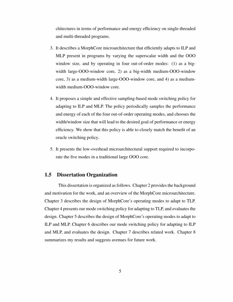
executing them in program order. Figure 2.1 shows a high-level layout of a 2-way
SMT OOO core pipeline, including the major structures accessed and functionality
performed in different stages of the pipeline. We describe a Pentium-4 like ar-
chitecture [35], where the data, both speculative and architectural, is stored in the
Physical Register File (PRF), and the per-thread Register Alias Table (RAT) entries
point to PRF entries. The front-end Speculative-RAT points to the speculative state,
and a back-end Permanent-RAT points to the architectural state. The front-end of
the pipeline (from the Fetch stage until the Insert into Reservation Station (RS))
works in-order. Instructions are fetched, decoded, and sent to the Rename Stage.
The Rename stage renames (i.e. maps) the architectural source and destination
register IDs into Physical Register File IDs by reading the Speculative-RAT of the
thread for which instructions are being renamed, and inserts the instructions into
the Reservation Station (also referred to as the Issue Queue).
Instructions wait in the Reservation Station until they are selected for ex-
ecution by the Select stage. The Select stage selects an instruction for execution
once all of the source operands of the instruction are ready, and the instruction is
the oldest among the ready instructions. When an instruction is selected for exe-
cution, it readies its dependent instructions via the Wakeup Logic block, reads its
source operands from the PRF, and executes in a Functional Unit. After execution,
an instruction’s result is broadcast on the Bypass Network, so that any dependent
6
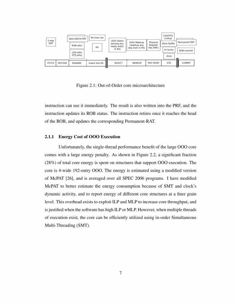
Figure 2.1: Out-of-Order core microarchitecture
instruction can use it immediately. The result is also written into the PRF, and the
instruction updates its ROB status. The instruction retires once it reaches the head
of the ROB, and updates the corresponding Permanent-RAT.
2.1.1 Energy Cost of OOO Execution
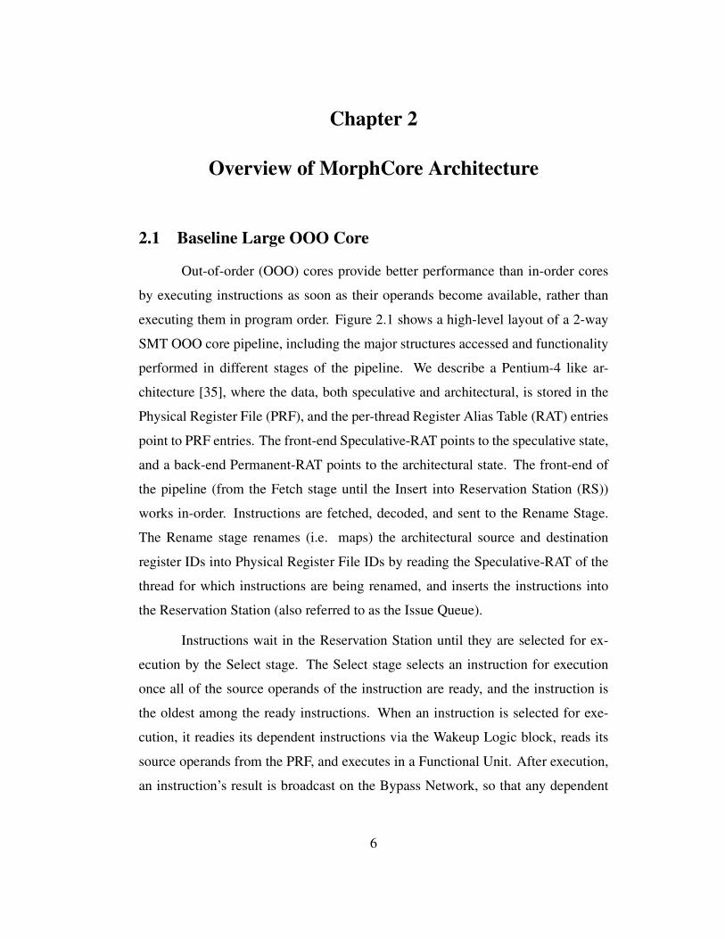
Unfortunately, the single-thread performance benefit of the large OOO core
comes with a large energy penalty. As shown in Figure 2.2, a significant fraction
(28%) of total core energy is spent on structures that support OOO execution. The
core is 4-wide 192-entry OOO. The energy is estimated using a modified version
of McPAT [26], and is averaged over all SPEC 2006 programs. I have modified
McPAT to better estimate the energy consumption because of SMT and clock’s
dynamic activity, and to report energy of different core structures at a finer grain
level. This overhead exists to exploit ILP and MLP to increase core throughput, and
is justified when the software has high ILP or MLP. However, when multiple threads
of execution exist, the core can be efficiently utilized using in-order Simultaneous
Multi-Threading (SMT).
7
0
10
20
30
40
50
60
70
80
90
100
Fra
ctio
n o
f en
ergy (
%)
Dcache + TLBInst Fetch Unit
OOO (Rename + Scheduler + LSQ + ROB)Physical Reg File
Execution
Figure 2.2: Fraction of energy spent on different hardware resources
2.2 Adapting to TLP
Simultaneous Multi-Threading (SMT) [14, 47, 42] is a technique to improve
the utilization of execution resources using multiple threads provided by the soft-
ware. In SMT, a core executes instructions from multiple threads concurrently. Ev-
ery cycle, the core picks a thread from potentially many ready threads, and fetches
instructions from that thread. The instructions are then decoded and renamed in a
regular pipelined fashion and inserted into a common (shared among all the threads)
Reservation Station (RS). Since instructions from multiple candidate threads are
available in the RS, the possibility of finding ready instructions increases. Thus,
SMT cores can achieve higher throughput provided that software exposes multiple
threads to the hardware.
2.2.1 The Potential of In-Order SMT
The observation that a highly multi-threaded in-order core can achieve the
instruction issue throughput similar to an OOO core was noted by Hily and Seznec
[13]. We build on this insight to design a core that can achieve high-performance
and low-energy consumption when software parallelism is available.
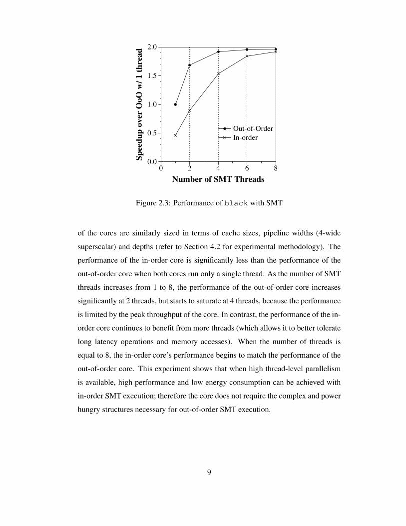
Figure 2.3 shows the performance of the workload black (Black-Scholes
pricing [30]) on an out-of-order and an in-order core. For this experiment, both
8
0 2 4 6 80.0
0.5
1.0
1.5
2.0
Sp
eed
up
ov
er O
oO
w/
1 t
hre
ad
Out-of-Order
In-order
Number of SMT Threads
Figure 2.3: Performance of black with SMT
of the cores are similarly sized in terms of cache sizes, pipeline widths (4-wide
superscalar) and depths (refer to Section 4.2 for experimental methodology). The
performance of the in-order core is significantly less than the performance of the
out-of-order core when both cores run only a single thread. As the number of SMT
threads increases from 1 to 8, the performance of the out-of-order core increases
significantly at 2 threads, but starts to saturate at 4 threads, because the performance
is limited by the peak throughput of the core. In contrast, the performance of the in-
order core continues to benefit from more threads (which allows it to better tolerate
long latency operations and memory accesses). When the number of threads is
equal to 8, the in-order core’s performance begins to match the performance of the
out-of-order core. This experiment shows that when high thread-level parallelism
is available, high performance and low energy consumption can be achieved with
in-order SMT execution; therefore the core does not require the complex and power
hungry structures necessary for out-of-order SMT execution.
9
2.2.2 Repurposing Core’s Resources
A key insight behind MorphCore’s design is that a highly-threaded in-order
SMT core can be built using a subset of the hardware required to build an aggressive
out-of-order core. For example, we use the Physical Register File (PRF) in the out-
of-order core as the architectural register files for the many SMT threads in InOrder
mode. Similarly, we use the Reservation Station entries as an in-order instruction
buffer and the execution pipeline of the out-of-order core as-is. This efficiently
increases the utilization of the core’s resources and increases both performance and
energy efficiency.
2.2.3 Operating Modes
In spite of its high energy cost, out-of-order execution is still desirable be-
cause it provides significant performance improvement over in-order execution.
Thus, if we want high single-thread performance we must maintain support for
out-of-order execution. However, when software parallelism is available, we can
efficiently provide performance by using in-order SMT and not waste energy on
out-of-order execution. To accomplish both, we propose the two operating modes
of MorphCore: OutofOrder and InOrder. In OutofOrder mode, MorphCore works
exactly like a traditional out-of-order core. In InOrder mode, MorphCore supports
additional in-order SMT threads, and in-order scheduling, execution, and commit
of simultaneously running threads.
2.3 Adapting to ILP and MLP
Single thread performance and energy efficiency are both key to any mod-
ern general-purpose core design. Architects in industry are trying to maximize
performance without increasing energy consumption. Industry is increasing single
thread performance by increasing the superscalar width and the OOO window size.
Increasing width increases the number of instructions that are fetched, decoded, re-
named and allocated per cycle, so that more and more instructions are exposed to
10
the execution engine (which also has the ability to execute and commit at an in-
creased rate), potentially increasing the ILP and thus the performance. Increasing
the OOO window size increases the number of “in-flight” instructions by increas-
ing the number of ROB, Physical Register file (PRF), load/store queue (LSQ) and
scheduler (RS) entries. This increases the microprocessor’s ability to tolerate laten-
cies, as well as its ability to expose parallel cache misses (known as Memory-Level
Parallelism or MLP), both of which increase performance.
0
10
20
30
40
50
60
70
80
90
100
Fra
ctio
n o
f en
ergy
(%
)
Pipeline (clock + latches)Dcache + TLB
DecodeFetch
Out-of-OrderBypass
Execution
Figure 2.4: Fraction of energy per instruction spent on different hardware resources
2.3.1 Energy Cost of Wide Width
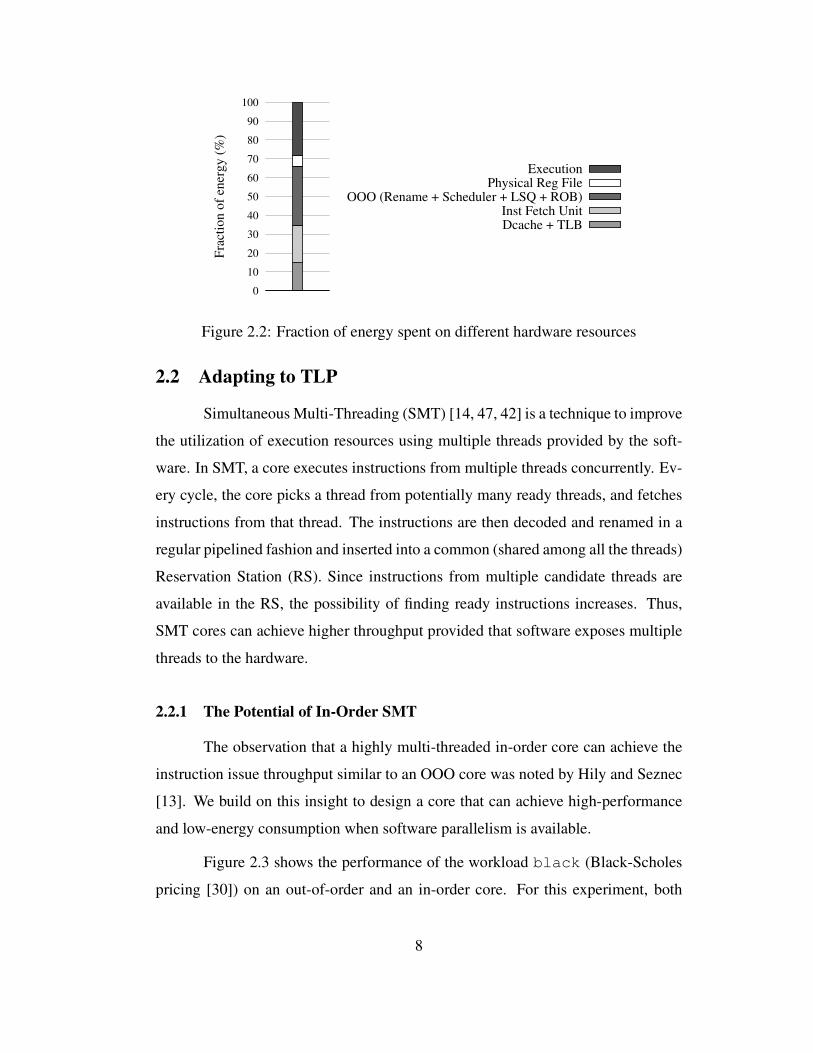
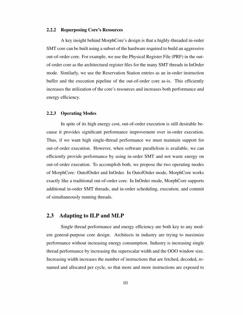
These high performance features cost significant energy consumption. Fig-
ure 2.4 shows the fraction of Energy Per Instruction (EPI) spent on different hard-
ware structures of a 4-wide 192-entry ROB OOO core (averaged over all SPEC
2006 programs). Energy is estimated using a modified version of McPAT 0.8 [26].
The two biggest sources of energy consumption are out-of-order execution struc-
tures (Rename, ROB, PRF, LSQ, and RS) and deep and wide pipeline (more specif-
ically, pipeline latches and clock network). A deep pipeline enables high frequency
operation, and a wider pipeline improves instruction throughput per cycle.
11
2.3.2 Problem: Different Programs Benefit Differently from Wide Width and/or
Large OOO Window
Increasing pipeline width and OOO window size benefits different work-
loads differently. For example, compute bound workloads can benefit from a wider
pipeline as well as a larger window, however, memory bound workloads only ben-
efit from a larger window size, if at all.
0
20
40
60
80
100
perl
hmm
er
mcf
milc
leslie
Gem
s
deal
II
IPC
norm
aliz
ed t
o
4-w
ide
192-e
ntr
y O
OO
(%
)
4-wide 192-entry OOO2-wide InOrder
2-wide, 192-entry OOO2-wide, 48-entry OOO4-wide, 48-entry OOO
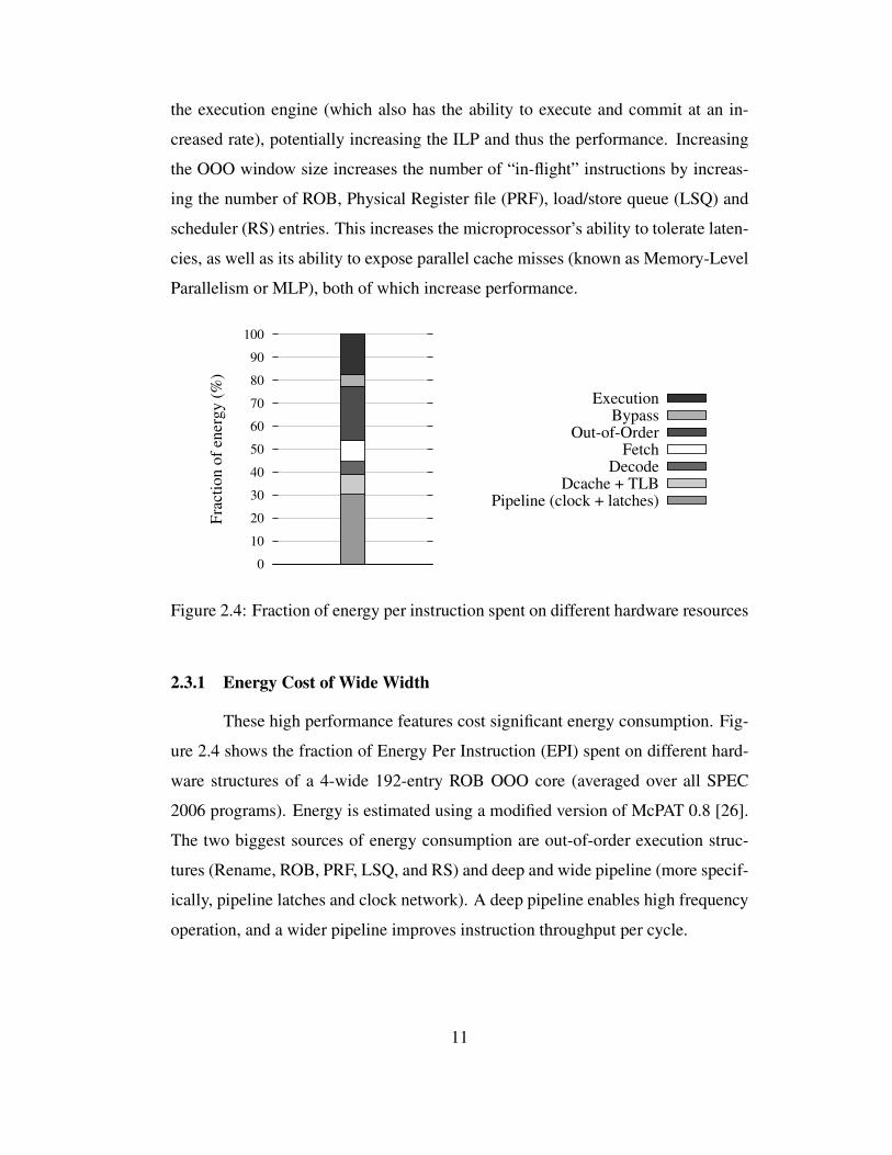
Figure 2.5: Performance of cores with different widths and execution substrates.
Figure 2.5 plots performance of four different less aggressive core config-
urations for seven SPEC2006 benchmarks normalized to a large more aggressive
OOO core (4-wide and 192-entry OOO window). The four less aggressive core
configurations are: a 2-wide in-order, a 2-wide 192-entry OOO, a 2-wide 48-entry
OOO, and a 4-wide 48-entry OOO. The memory hierarchy is the same across all
core configurations. Note that the 2-wide InOrder core loses performance signifi-
cantly on all 7 benchmarks. The experiment also shows that wide width and large
OOO window do not always help to increase performance significantly. For ex-
12
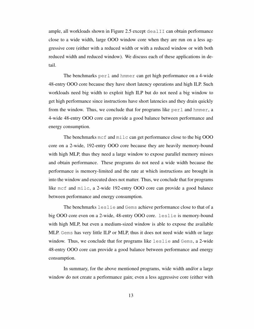
ample, all workloads shown in Figure 2.5 except dealII can obtain performance
close to a wide width, large OOO window core when they are run on a less ag-
gressive core (either with a reduced width or with a reduced window or with both
reduced width and reduced window). We discuss each of these applications in de-
tail.
The benchmarks perl and hmmer can get high performance on a 4-wide
48-entry OOO core because they have short latency operations and high ILP. Such
workloads need big width to exploit high ILP but do not need a big window to
get high performance since instructions have short latencies and they drain quickly
from the window. Thus, we conclude that for programs like perl and hmmer, a
4-wide 48-entry OOO core can provide a good balance between performance and
energy consumption.
The benchmarks mcf and milc can get performance close to the big OOO
core on a 2-wide, 192-entry OOO core because they are heavily memory-bound
with high MLP, thus they need a large window to expose parallel memory misses
and obtain performance. These programs do not need a wide width because the
performance is memory-limited and the rate at which instructions are brought in
into the window and executed does not matter. Thus, we conclude that for programs
like mcf and milc, a 2-wide 192-entry OOO core can provide a good balance
between performance and energy consumption.
The benchmarks leslie and Gems achieve performance close to that of a
big OOO core even on a 2-wide, 48-entry OOO core. leslie is memory-bound
with high MLP, but even a medium-sized window is able to expose the available
MLP. Gems has very little ILP or MLP, thus it does not need wide width or large
window. Thus, we conclude that for programs like leslie and Gems, a 2-wide
48-entry OOO core can provide a good balance between performance and energy
consumption.
In summary, for the above mentioned programs, wide width and/or a large
window do not create a performance gain; even a less aggressive core (either with
13
reduced-width, or with reduced-window, or with reduced-window and reduced-
width) can provide performance close to a big OOO core. For such workloads,
hardware supported wide width and large OOO window is inefficient.
Finally, dealII is an example of a program that needs a wide width and a
large window to achieve high performance. dealII’s instructions on average have
longer latencies, and thus, a small window stalls frequently. With a large window,
the instruction stream exposes high ILP, which makes it possible to get a significant
performance boost with a wider core.
The data presented in Figures 2.4 and 2.5 motivates the need for an adaptive
out-of-order core that dynamically varies its width and window to the needs of
the program in order to achieve a balance between high performance and energy
efficiency.
2.3.3 Our Solution: Dynamically Vary Width and Window Size
(b) OutofOrder Mode4−wide, 192−entry OOO
Width
Size
Pipeline
OOO Window
Depth
Pipeline
(a) MorphCore Architecture
(192−entry)(4−wide)
4−wide, 192−entry window
(c) 4−wide, 48−entry OOO Mode
(d) 2−wide, 192−entry OOO Mode
(e) 2−wide, 48−entry OOO Mode
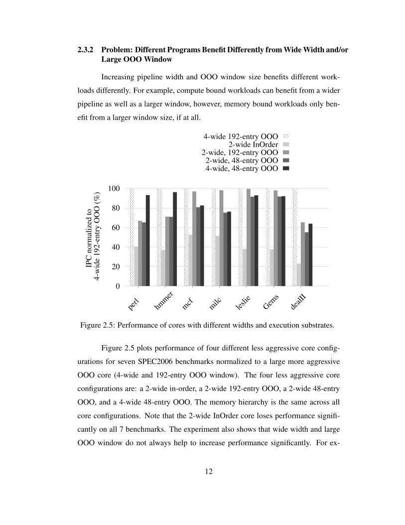
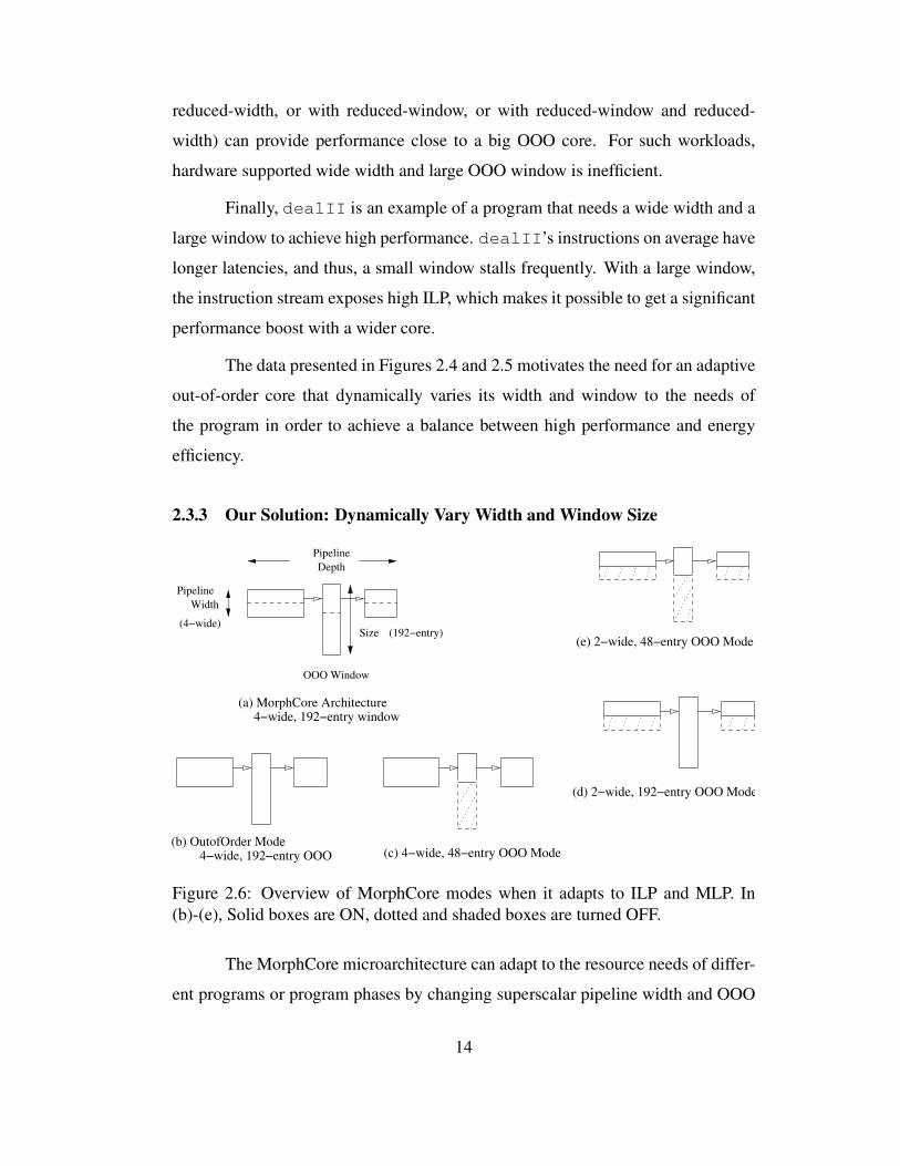
Figure 2.6: Overview of MorphCore modes when it adapts to ILP and MLP. In
(b)-(e), Solid boxes are ON, dotted and shaded boxes are turned OFF.
The MorphCore microarchitecture can adapt to the resource needs of differ-
ent programs or program phases by changing superscalar pipeline width and OOO
14
window size. Figure 2.6 (a) shows the MorphCore microarchitecture. It supports
wide superscalar width and large OOO execution window. In addition, it also has
microarchitectural support for reducing the pipeline width and the window size
(shown with dotted lines). Because MorphCore can vary two parameters, width
and window, MorphCore provides four out-of-order operating modes as shown in
Figure 2.6 (b)-(e). The modes are: 4-wide 192-entry OOO, 4-wide 48-entry OOO,
2-wide 192-entry OOO, and 2-wide 48-entry OOO. The 4-wide 192-entry OOO
mode is the fully-provisioned high-power and high-performance mode, whereas
the other three modes are “low-provisioned” low-power low-performance modes.
Our goal with the MorphCore microarchitecture is to provide high perfor-
mance and, when needed, energy efficiency for single-threaded programs. Mor-
phCore continuously monitors the executing workload and makes intelligent de-
cisions to change the width and the window size. It employs a simple yet effec-
tive sampling-based mode switching policy that periodically samples the perfor-
mance and energy of each of the four out-of-order operating modes, and chooses
the width/window size that will lead to the desired goal of performance or energy
efficiency.
15
Chapter 3
Adapting to Thread-Level Parallelism (TLP)
3.1 MorphCore Microarchitecture
3.1.1 Overview
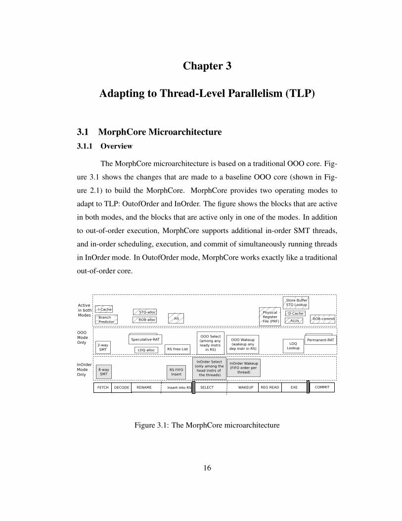
The MorphCore microarchitecture is based on a traditional OOO core. Fig-
ure 3.1 shows the changes that are made to a baseline OOO core (shown in Fig-
ure 2.1) to build the MorphCore. MorphCore provides two operating modes to
adapt to TLP: OutofOrder and InOrder. The figure shows the blocks that are active
in both modes, and the blocks that are active only in one of the modes. In addition
to out-of-order execution, MorphCore supports additional in-order SMT threads,
and in-order scheduling, execution, and commit of simultaneously running threads
in InOrder mode. In OutofOrder mode, MorphCore works exactly like a traditional
out-of-order core.
Figure 3.1: The MorphCore microarchitecture
16
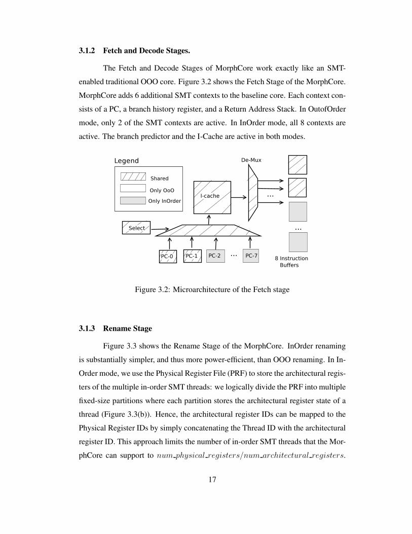
3.1.2 Fetch and Decode Stages.
The Fetch and Decode Stages of MorphCore work exactly like an SMT-
enabled traditional OOO core. Figure 3.2 shows the Fetch Stage of the MorphCore.
MorphCore adds 6 additional SMT contexts to the baseline core. Each context con-
sists of a PC, a branch history register, and a Return Address Stack. In OutofOrder
mode, only 2 of the SMT contexts are active. In InOrder mode, all 8 contexts are
active. The branch predictor and the I-Cache are active in both modes.
Figure 3.2: Microarchitecture of the Fetch stage
3.1.3 Rename Stage
Figure 3.3 shows the Rename Stage of the MorphCore. InOrder renaming
is substantially simpler, and thus more power-efficient, than OOO renaming. In In-
Order mode, we use the Physical Register File (PRF) to store the architectural regis-
ters of the multiple in-order SMT threads: we logically divide the PRF into multiple
fixed-size partitions where each partition stores the architectural register state of a
thread (Figure 3.3(b)). Hence, the architectural register IDs can be mapped to the
Physical Register IDs by simply concatenating the Thread ID with the architectural
register ID. This approach limits the number of in-order SMT threads that the Mor-
phCore can support to num physical registers/num architectural registers.
17
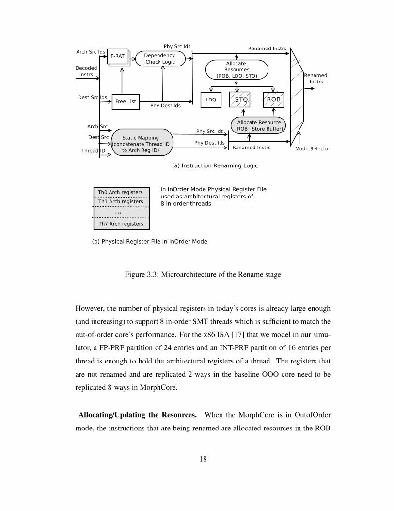
Figure 3.3: Microarchitecture of the Rename stage
However, the number of physical registers in today’s cores is already large enough
(and increasing) to support 8 in-order SMT threads which is sufficient to match the
out-of-order core’s performance. For the x86 ISA [17] that we model in our simu-
lator, a FP-PRF partition of 24 entries and an INT-PRF partition of 16 entries per
thread is enough to hold the architectural registers of a thread. The registers that
are not renamed and are replicated 2-ways in the baseline OOO core need to be
replicated 8-ways in MorphCore.
Allocating/Updating the Resources. When the MorphCore is in OutofOrder
mode, the instructions that are being renamed are allocated resources in the ROB
18
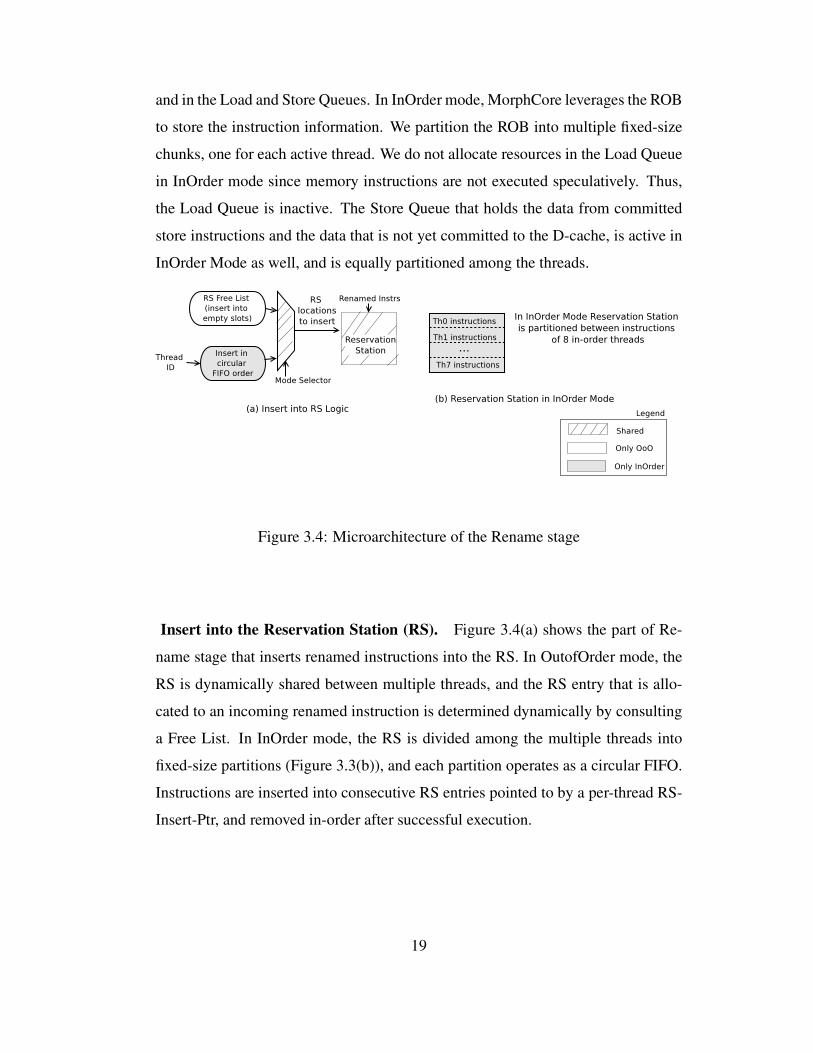
and in the Load and Store Queues. In InOrder mode, MorphCore leverages the ROB
to store the instruction information. We partition the ROB into multiple fixed-size
chunks, one for each active thread. We do not allocate resources in the Load Queue
in InOrder mode since memory instructions are not executed speculatively. Thus,
the Load Queue is inactive. The Store Queue that holds the data from committed
store instructions and the data that is not yet committed to the D-cache, is active in
InOrder Mode as well, and is equally partitioned among the threads.
Figure 3.4: Microarchitecture of the Rename stage
Insert into the Reservation Station (RS). Figure 3.4(a) shows the part of Re-
name stage that inserts renamed instructions into the RS. In OutofOrder mode, the
RS is dynamically shared between multiple threads, and the RS entry that is allo-
cated to an incoming renamed instruction is determined dynamically by consulting
a Free List. In InOrder mode, the RS is divided among the multiple threads into
fixed-size partitions (Figure 3.3(b)), and each partition operates as a circular FIFO.
Instructions are inserted into consecutive RS entries pointed to by a per-thread RS-
Insert-Ptr, and removed in-order after successful execution.
19
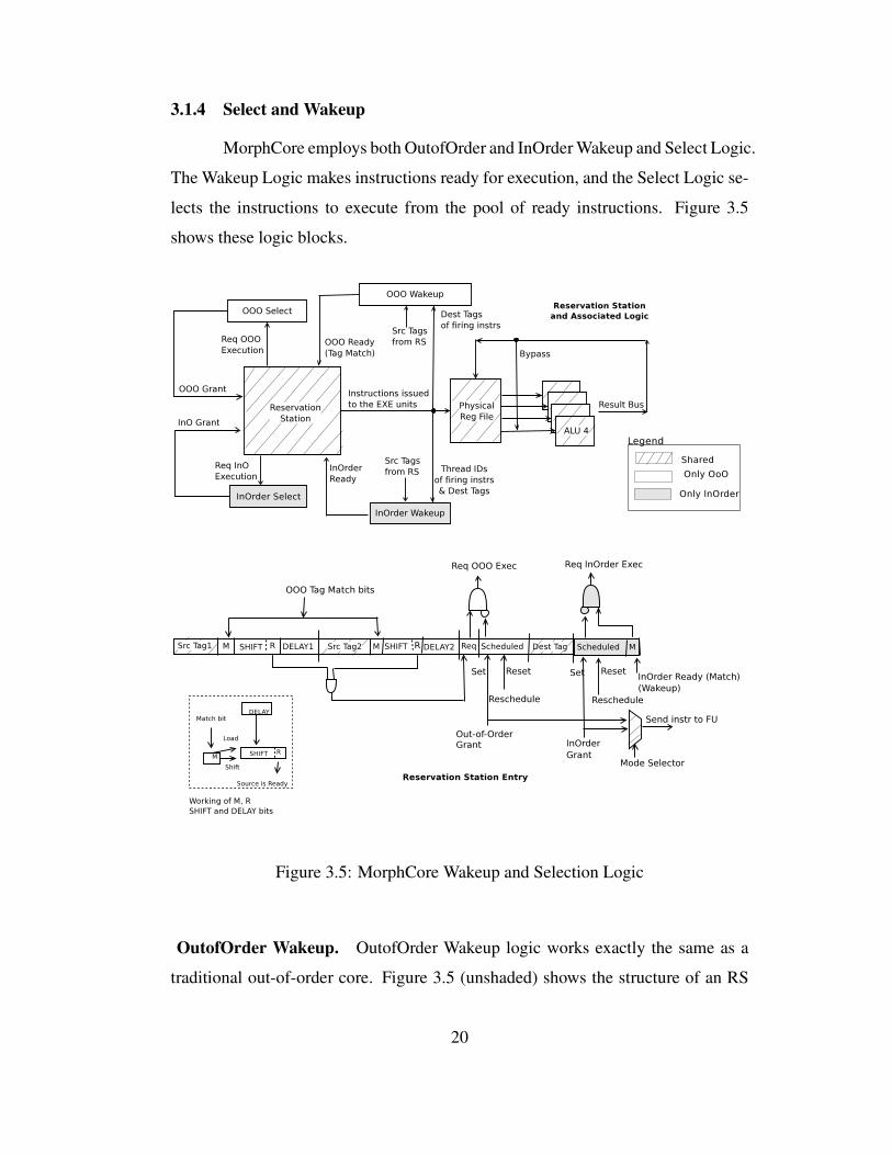
3.1.4 Select and Wakeup
MorphCore employs both OutofOrder and InOrder Wakeup and Select Logic.
The Wakeup Logic makes instructions ready for execution, and the Select Logic se-
lects the instructions to execute from the pool of ready instructions. Figure 3.5
shows these logic blocks.
Figure 3.5: MorphCore Wakeup and Selection Logic
OutofOrder Wakeup. OutofOrder Wakeup logic works exactly the same as a
traditional out-of-order core. Figure 3.5 (unshaded) shows the structure of an RS
20
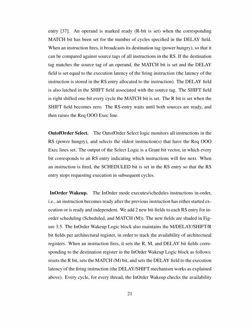
entry [37]. An operand is marked ready (R-bit is set) when the corresponding
MATCH bit has been set for the number of cycles specified in the DELAY field.
When an instruction fires, it broadcasts its destination tag (power hungry), so that it
can be compared against source tags of all instructions in the RS. If the destination
tag matches the source tag of an operand, the MATCH bit is set and the DELAY
field is set equal to the execution latency of the firing instruction (the latency of the
instruction is stored in the RS entry allocated to the instruction). The DELAY field
is also latched in the SHIFT field associated with the source tag. The SHIFT field
is right shifted one-bit every cycle the MATCH bit is set. The R bit is set when the
SHIFT field becomes zero. The RS-entry waits until both sources are ready, and
then raises the Req OOO Exec line.
OutofOrder Select. The OutofOrder Select logic monitors all instructions in the
RS (power hungry), and selects the oldest instruction(s) that have the Req OOO
Exec lines set. The output of the Select Logic is a Grant bit vector, in which every
bit corresponds to an RS entry indicating which instructions will fire next. When
an instruction is fired, the SCHEDULED bit is set in the RS entry so that the RS
entry stops requesting execution in subsequent cycles.
InOrder Wakeup. The InOrder mode executes/schedules instructions in-order,
i.e., an instruction becomes ready after the previous instruction has either started ex-
ecution or is ready and independent. We add 2 new bit-fields to each RS entry for in-
order scheduling (Scheduled, and MATCH (M)). The new fields are shaded in Fig-
ure 3.5. The InOrder Wakeup Logic block also maintains the M/DELAY/SHIFT/R
bit fields per architectural register, in order to track the availability of architectural
registers. When an instruction fires, it sets the R, M, and DELAY bit fields corre-
sponding to the destination register in the InOrder Wakeup Logic block as follows:
resets the R bit, sets the MATCH (M) bit, and sets the DELAY field to the execution
latency of the firing instruction (the DELAY/SHIFT mechanism works as explained
above). Every cycle, for every thread, the InOrder Wakeup checks the availability
21
of source registers of the two oldest instructions (R bit is set). If the sources are
available, the Wakeup logic readies the instructions by setting the M bit in the RS
entry to 1. The InOrder Wakeup is power-efficient since it avoids the broadcast and
matching of the destination tag against the source operands of all instructions in the
RS.
InOrder Select. The InOrder Select Logic block works hierarchically in a complexity-
effective (power-efficient) manner by maintaining eight InOrder select blocks (one
per thread) and another block to select between the outcomes of these blocks. Fur-
thermore, each in-order select logic only monitors the two oldest instructions in the
thread’s RS partition, rather than monitoring the entire RS as in OOO select. Note
that only two instructions need monitoring in InOrder mode because instructions
from each thread are inserted and scheduled/removed in a FIFO manner.
3.1.5 Execution and Commit
When an instruction is selected for execution, it reads its source operands
from the PRF, executes in an ALU, and broadcasts its result on the bypass network
as done in a traditional OOO core. In MorphCore, an additional PRF-bypass and
additional data storage are active in InOrder mode. This bypass and buffering is
provided in order to delay the write of younger instruction(s) in the PRF if an older
longer latency instruction is in the execution pipeline. In such a case, younger
instruction(s) write into a temporary small data buffer (4-entry per thread). The
buffer adds an extra bypass in the PRF-read stage. Instructions commit in traditional
SMT fashion. For OutofOrder commit, the Permanent-RAT is updated as well. In
InOrder mode, only the thread’s ROB Head pointer needs to be updated.
3.1.6 Load/Store Unit
Figure 3.6 shows the Load/Store Unit. In OutofOrder mode, load/store in-
structions are executed speculatively and out of order (similar to a traditional OOO
core). When a load fires, it updates its entry in the Load Queue and searches the
22
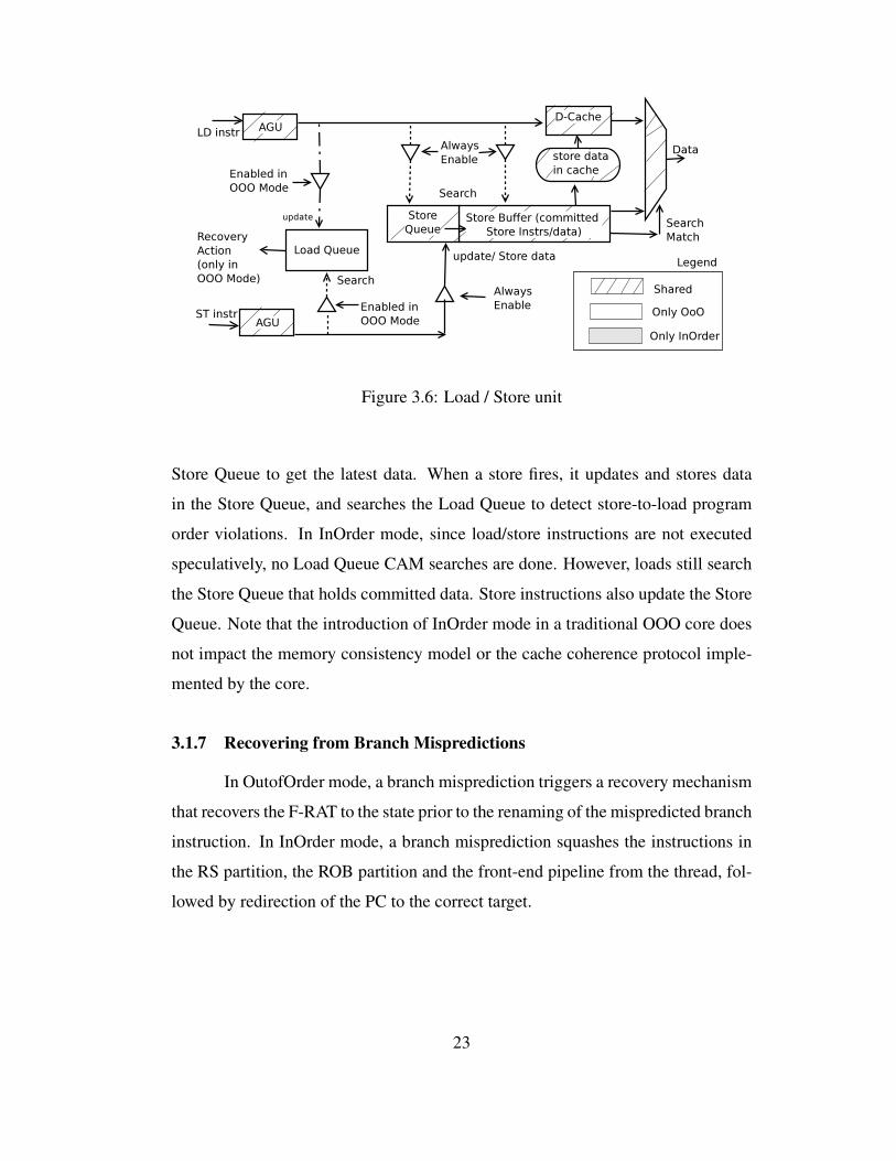
Figure 3.6: Load / Store unit
Store Queue to get the latest data. When a store fires, it updates and stores data
in the Store Queue, and searches the Load Queue to detect store-to-load program
order violations. In InOrder mode, since load/store instructions are not executed
speculatively, no Load Queue CAM searches are done. However, loads still search
the Store Queue that holds committed data. Store instructions also update the Store
Queue. Note that the introduction of InOrder mode in a traditional OOO core does
not impact the memory consistency model or the cache coherence protocol imple-
mented by the core.
3.1.7 Recovering from Branch Mispredictions
In OutofOrder mode, a branch misprediction triggers a recovery mechanism
that recovers the F-RAT to the state prior to the renaming of the mispredicted branch
instruction. In InOrder mode, a branch misprediction squashes the instructions in
the RS partition, the ROB partition and the front-end pipeline from the thread, fol-
lowed by redirection of the PC to the correct target.
23
3.2 MorphCore Discussion
3.2.1 Area and Power Overhead of MorphCore
First, MorphCore increases the number of SMT ways from 2 to 8. This adds
hardware to the Fetch stage and other parts of the core, which is less than 0.5% area
overhead as reported by our modified McPAT [26] tool (the core area includes the
area of the first-level instruction cache and data cache). Note that it does not incur
the two biggest overheads of adding SMT contexts in an OOO core –additional
Rename tables and physical registers– because the SMT contexts being added are
in-order. Second, MorphCore adds InOrder Wakeup and Select logic, which we
assume adds an area overhead of less than 0.5% of core area, half the area of the
OOO Wakeup and Select logic blocks. Third, adding extra bypass/buffering adds
an area overhead of 0.5% of core. Thus, MorphCore adds an area overhead of 1.5%,
and a power overhead of 1.5% in InOrder mode.
3.2.2 Timing/Frequency Impact of MorphCore
MorphCore requires only two key changes to the baseline OOO core:
1) InOrder renaming/scheduling/execution logic. MorphCore adds a multi-
plexer in the critical path of three stages: a) in the Rename stage to select between
OutofOrder mode and InOrder mode renamed instructions, b) in the Instruction
Scheduling stage to select between the OutofOrder mode and InOrder mode ready
instructions, and c) in PRF-read stage because of additional bypassing in InOrder
mode. In order to estimate the frequency impact of this overhead, we assume that
a multiplexer introduces a delay of one transmission gate, which we assume to be
half of an FO4 gate delay. Assuming 20 FO4 gate delays per pipeline stage [45, 7],
we estimate that MorphCore runs 2.5% slower than the baseline OOO core.
2) More SMT contexts. Addition of in-order SMT contexts can lengthen
the thread selection logic in MorphCore’s front-end. This overhead is changing the
multiplexer that selects one out of many ready threads from 2-to-1 to 8-to-1. We
assume that running MorphCore 2.5% slower than the baseline OOO core hides this
24

delay.
In addition to the above mentioned timing-critical changes to the baseline
OOO core, MorphCore adds InOrder Wakeup and Select logic blocks. Because
InOrder instruction scheduling is simpler than OutofOrder instruction scheduling,
we assume that newly added blocks can be placed and routed such that they do not
affect the critical path of other components of the baseline OOO core. Thus, we
conclude that the frequency impact of MorphCore is only 2.5%.
3.2.3 Turning Off Structures in InOrder Mode
The structures that are inactive in InOrder Mode are either clock-gated
(OOO scheduling and load queue) or power-gated (OOO renaming logic).
3.2.4 Interaction with OS
MorphCore does not require any changes to the operating system, and acts
like a core with the number of hardware threads equal to the maximum number
of threads supported in the InOrder Mode (8 in our implementation). Switching
between the two modes is handled in hardware.
25
Chapter 4
Mode Switching Policy for Adapting to TLP and
Evaluation
In Chapter 3, I introduced two of the five modes supported by the Mor-
phCore microarchitecture: OutOfOrder and InOrder. The OutOfOrder mode is
4-wide superscalar and 192-entry out-of-order whereas InOrder mode is 4-wide
superscalar 8-way threaded in-order SMT. This chapter describes the policy that
we use to switch between these two modes when the MorphCore microarchitecture
adapts to TLP, and evaluates its performance and energy efficiency.
4.1 When to Operate in OutofOrder Mode or in InOrder Mode?
The current implementation of MorphCore switches between OutofOrder
and InOrder modes based on the number of active threads. A thread is active when it
is not waiting for a synchronization event. We assume that the threading library uses
MONITOR/MWAIT [17] instructions such that MorphCore hardware can detect a
thread becoming inactive, e.g., inactive at a barrier waiting for other threads to
reach the barrier, or inactive at a lock-acquire waiting for another thread to release
the lock. The hardware makes the thread active when a write to the cacheline being
monitored is detected.
MorphCore operates in OutofOrder mode when the number of active threads
is fewer than or equal to 2. The rationale here is that when TLP is limited, execut-
ing OOO is the best and only way to obtain performance and energy efficiency.
I show in Section 5.1 that 2-wide in-order execution not only loses performance
significantly but increases energy consumption as well. MorphCore operates in In-
Order when the number of active threads is greater than 2. The rationale here is that
26

high core throughput can be obtained by executing the many available threads in-
order while saving energy. MorphCore starts running in OutofOrder mode when the
number of active threads is fewer than 2. If the OS schedules more threads on Mor-
phCore, and the number of active threads becomes greater than 2, the core switches
to InOrder mode. While running in InOrder mode, the number of active threads can
drop for two reasons: the OS can de-schedule some threads or the threads can be-
come inactive waiting for synchronization. If the number of active threads becomes
smaller than or equal to 2, the core switches back to OutofOrder mode until more
threads are scheduled or become active.
4.1.1 Changing Mode from OutofOrder to InOrder
Mode switching is handled by a micro-code routine that performs the fol-
lowing tasks:
1) Drains the core pipeline.
2) Spills the architectural registers of all threads. These registers are spilled
to a reserved memory region. To avoid cache misses on these writes, we use Full
Cache Line Write instructions that do not read the cache line before the write [17].
3) Disables the Renaming unit, OutofOrder Wakeup and Select Logic blocks,
and Load Queue. Note that these units do not necessarily need to be power-gated
(we assume that these units are clock-gated).
4) Fills the register values back into each thread’s PRF partitions. This is
done using special load micro-ops that directly address the PRF entries without
going through renaming.
4.1.2 Changing Mode from InOrder to OutofOrder
MorphCore supports eight threads in InOrder mode and two threads in Out-
ofOrder mode. When MorphCore changes mode from InOrder to OutofOrder, only
two of the eight threads can be executed. Thus six of the eight threads are marked
inactive or “not running” (unless they are already inactive, which is the case in
27

our current implementation). The state of the inactive threads is stored in memory
until they become active. To load the state of the active threads, the MorphCore
stores pointers to the architectural state of the inactive threads in a structure called
the Active Threads Table. The Active Threads Table is indexed using the Thread
ID, and stores an 8-byte pointer for each thread. Mode switching is handled by a
micro-code routine that performs the following tasks:
1) Drains the core pipeline.
2) Spills the architectural registers of all threads, and stores the pointers to
the architectural state of the inactive threads in the Active Thread Table.
3) Enables the Renaming unit, OutofOrder Wakeup and Select Logic blocks,
and Load Queue.
4) Fills the architectural registers of only the active threads into pre-determined
locations in PRF, and updates the Speculative-RAT and Permanent-RAT.
4.1.3 Overhead of Changing the Mode
The overhead of changing the mode is pipeline drain, which varies with the
workload, and the spill or fill of the architectural register state of the threads. The
x86 ISA [17] specifies an architectural state of ∼780 bytes per thread (including
the latest AVX extensions). The micro-code routine takes ∼30 cycles to spill or
fill the architectural register state of each thread after the pipeline drain (a total of
∼6KB and ∼250 cycles for 8 threads) into reserved ways of the private L2 cache
(assuming a 256 bit wide read/write port to the cache, and a cache bandwidth of 1
read/write per cycle). We have empirically observed a loss in performance of only
less than 1% by reserving 6KB in the private 256KB cache. Note that the overhead
of changing the mode can be reduced significantly by overlapping the spilling or
filling of the architectural state with the pipeline drain.
28
4.1.4 Handling Medium TLP
MorphCore operates in InOrder mode when the number of active threads is
greater than 2. This policy works best when the number of active threads is max-
imum, i.e., 8, since many active threads sustain a high core throughput even when
running in-order. However, the number of active threads can change at runtime.
When only a few threads are active (e.g., 3-5), executing those threads in-order in
InOrder mode may not achieve a high core throughput, and in fact may even reduce
performance as compared to the baseline OOO-2 core (or OutofOrder mode).
A solution to this problem is to switch into OutofOrder mode when the
medium number of active threads cannot sustain a high core throughput in InOrder
mode but OOO execution can in OutofOrder mode. Detecting such situations and
making the necessary mode switching decisions are future research areas. Note that
the few active threads cannot all be run out-of-order simultaneously since the core
supports only 2 OOO contexts. A technique called Balanced Multithreading [43]
can be used to address this problem which proposes to time-multiplex the threads (2
at a time) onto a 2-SMT-context OOO processor when the number of active threads
(their “virtual context”) is greater than 2.
4.2 Experimental Methodology
Table 4.1 shows the configurations of the cores and the memory subsystem
simulated using our in-house cycle-level x86 simulator. The simulator faithfully
models microarchitectural details of the core, cache hierarchy and memory subsys-
tem, e.g., contention for shared resources, DRAM bank conflicts, banked caches,
etc. To estimate the area and energy of different core architectures, we use a modi-
fied version of McPAT [26]. We modified McPAT to: 1) report finer-grain area and
power data, 2) increase SMT ways without increasing the Rename (RAT) tables,
3) use the area/energy impact of InOrder scheduling (1/2 of OOO), 4) model extra
bypass/buffering, and 5) model the impact of SMT more accurately. Note that all
core configurations have the same memory subsystem (L2, L3 and main memory).
29
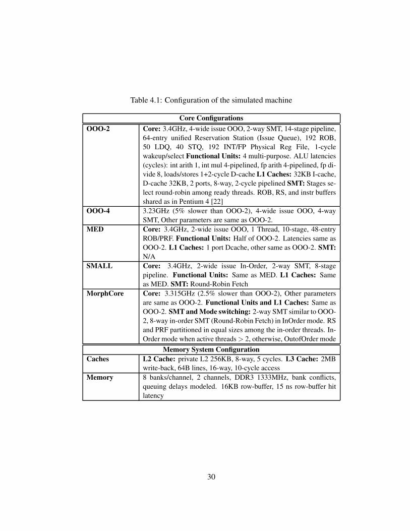
Table 4.1: Configuration of the simulated machine
Core Configurations
OOO-2 Core: 3.4GHz, 4-wide issue OOO, 2-way SMT, 14-stage pipeline,
64-entry unified Reservation Station (Issue Queue), 192 ROB,
50 LDQ, 40 STQ, 192 INT/FP Physical Reg File, 1-cycle
wakeup/select Functional Units: 4 multi-purpose. ALU latencies
(cycles): int arith 1, int mul 4-pipelined, fp arith 4-pipelined, fp di-
vide 8, loads/stores 1+2-cycle D-cache L1 Caches: 32KB I-cache,
D-cache 32KB, 2 ports, 8-way, 2-cycle pipelined SMT: Stages se-
lect round-robin among ready threads. ROB, RS, and instr buffers
shared as in Pentium 4 [22]
OOO-4 3.23GHz (5% slower than OOO-2), 4-wide issue OOO, 4-way
SMT, Other parameters are same as OOO-2.
MED Core: 3.4GHz, 2-wide issue OOO, 1 Thread, 10-stage, 48-entry
ROB/PRF. Functional Units: Half of OOO-2. Latencies same as
OOO-2. L1 Caches: 1 port Dcache, other same as OOO-2. SMT:
N/A
SMALL Core: 3.4GHz, 2-wide issue In-Order, 2-way SMT, 8-stage
pipeline. Functional Units: Same as MED. L1 Caches: Same
as MED. SMT: Round-Robin Fetch
MorphCore Core: 3.315GHz (2.5% slower than OOO-2), Other parameters
are same as OOO-2. Functional Units and L1 Caches: Same as
OOO-2. SMT and Mode switching: 2-way SMT similar to OOO-
2, 8-way in-order SMT (Round-Robin Fetch) in InOrder mode. RS
and PRF partitioned in equal sizes among the in-order threads. In-
Order mode when active threads > 2, otherwise, OutofOrder mode
Memory System Configuration
Caches L2 Cache: private L2 256KB, 8-way, 5 cycles. L3 Cache: 2MB
write-back, 64B lines, 16-way, 10-cycle access
Memory 8 banks/channel, 2 channels, DDR3 1333MHz, bank conflicts,
queuing delays modeled. 16KB row-buffer, 15 ns row-buffer hit
latency
30
Tables 4.2 and 4.3 summarize the key characteristics of the compared ar-
chitectures. We run the baseline OOO-2 core at 3.4GHz and scale the frequencies
of the other cores to incorporate the effects of both increase in area and critical-
path-delay. For example, OOO-4’s frequency is 5% lower than OOO-2 because
adding the 2 extra SMT threads significantly increases the area/complexity of the
core: it adds two extra Rename tables (RATs), at least a multiplexer at the end of
the Rename stage, and also adds extra buffering at the start of the Rename stage
(to select between 4, rather than 2 rename tables) which we estimate (using McPAT
0.8 [26]) to be an additional 5% area and thus lower frequency by 5%. MorphCore’s
frequency is reduced by 2.5% because its critical path increased by 2.5% (as ex-
plained in Section 3.2.2). We also perform a sensitivity study where we increase
the frequency penalty incurred by MorphCore’s design, and report the resulting
performance and energy.
Since the OOO-2 core has the highest frequency and supports 4-wide su-
perscalar OOO execution, we expect it to have the highest single thread (ST) per-
formance. Since the SMALL and MED cores have the highest aggregate ops/cycle,
we expect them to have the highest multi-threaded (MT) performance. We expect
the MorphCore to perform close to best in both ST and MT workloads.
4.2.1 Workloads
Table 4.4 shows the description and input-set for each application. We sim-
ulate all single-threaded SPEC 2006 applications and 14 multi-threaded applica-
tions from different domains. Each SPEC benchmark is run for 200M instructions
with ref input set, where the representative slice is chosen using a Simpoint-like
methodology. We do so since SPEC workloads are substantially longer (billions of
instructions), and easier to sample using existing techniques like SimPoint. Single-
threaded workloads run on a single core with other cores turned off. In contrast,
multi-threaded workloads run with the number of threads set equal to the number
of available contexts, i.e., numberofcores × numberofSMTcontexts. We run
all multi-threaded workloads to completion and count only useful instructions. We
31
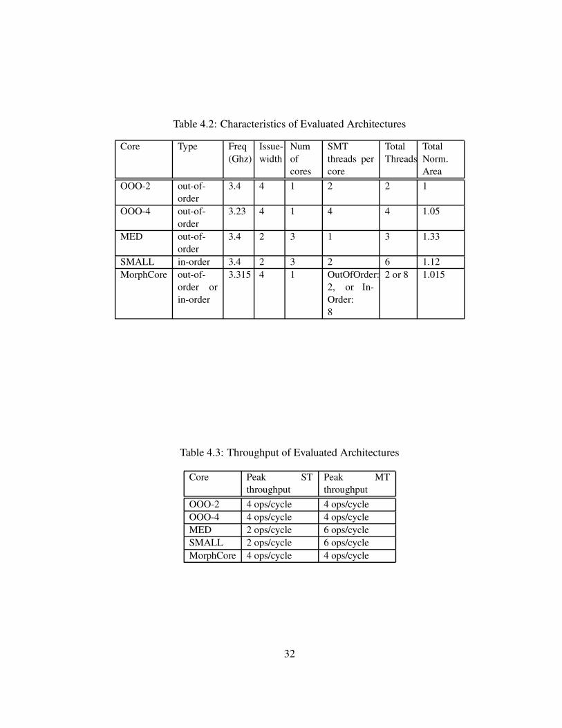
Table 4.2: Characteristics of Evaluated Architectures
Core Type Freq
(Ghz)
Issue-
width
Num
of
cores
SMT
threads per
core
Total
Threads
Total
Norm.
Area
OOO-2 out-of-
order
3.4 4 1 2 2 1
OOO-4 out-of-
order
3.23 4 1 4 4 1.05
MED out-of-
order
3.4 2 3 1 3 1.33
SMALL in-order 3.4 2 3 2 6 1.12
MorphCore out-of-
order or
in-order
3.315 4 1 OutOfOrder:
2, or In-
Order:
8
2 or 8 1.015
Table 4.3: Throughput of Evaluated Architectures
Core Peak ST
throughput
Peak MT
throughput
OOO-2 4 ops/cycle 4 ops/cycle
OOO-4 4 ops/cycle 4 ops/cycle
MED 2 ops/cycle 6 ops/cycle
SMALL 2 ops/cycle 6 ops/cycle
MorphCore 4 ops/cycle 4 ops/cycle
32
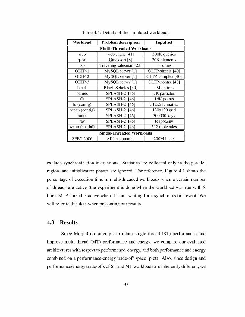
Table 4.4: Details of the simulated workloads
Workload Problem description Input set
Multi-Threaded Workloads
web web cache [41] 500K queries
qsort Quicksort [8] 20K elements
tsp Traveling salesman [23] 11 cities
OLTP-1 MySQL server [1] OLTP-simple [40]
OLTP-2 MySQL server [1] OLTP-complex [40]
OLTP-3 MySQL server [1] OLTP-nontrx [40]
black Black-Scholes [30] 1M options
barnes SPLASH-2 [46] 2K particles
fft SPLASH-2 [46] 16K points
lu (contig) SPLASH-2 [46] 512x512 matrix
ocean (contig) SPLASH-2 [46] 130x130 grid
radix SPLASH-2 [46] 300000 keys
ray SPLASH-2 [46] teapot.env
water (spatial) SPLASH-2 [46] 512 molecules
Single-Threaded Workloads
SPEC 2006 All benchmarks 200M instrs
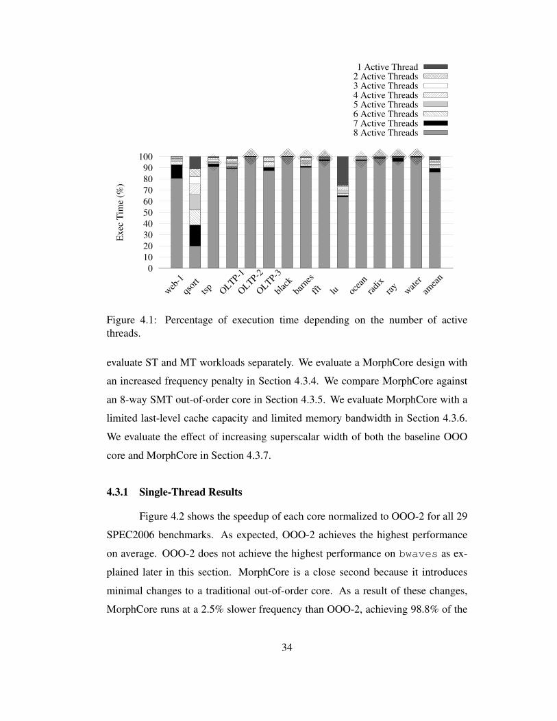
exclude synchronization instructions. Statistics are collected only in the parallel
region, and initialization phases are ignored. For reference, Figure 4.1 shows the
percentage of execution time in multi-threaded workloads when a certain number
of threads are active (the experiment is done when the workload was run with 8
threads). A thread is active when it is not waiting for a synchronization event. We
will refer to this data when presenting our results.
4.3 Results
Since MorphCore attempts to retain single thread (ST) performance and
improve multi thread (MT) performance and energy, we compare our evaluated
architectures with respect to performance, energy, and both performance and energy
combined on a performance-energy trade-off space (plot). Also, since design and
performance/energy trade-offs of ST and MT workloads are inherently different, we
33
0
10
20
30
40
50
60
70
80
90
100
web
-1
qsor
t
tsp
OLTP-1
OLTP-2
OLTP-3
blac
k
barn
es
fft
lu ocea
n
radi
xra
yw
ater
amea
n
Ex
ec T
ime
(%)
8 Active Threads7 Active Threads6 Active Threads5 Active Threads4 Active Threads3 Active Threads2 Active Threads1 Active Thread
Figure 4.1: Percentage of execution time depending on the number of active
threads.
evaluate ST and MT workloads separately. We evaluate a MorphCore design with
an increased frequency penalty in Section 4.3.4. We compare MorphCore against
an 8-way SMT out-of-order core in Section 4.3.5. We evaluate MorphCore with a
limited last-level cache capacity and limited memory bandwidth in Section 4.3.6.
We evaluate the effect of increasing superscalar width of both the baseline OOO
core and MorphCore in Section 4.3.7.
4.3.1 Single-Thread Results
Figure 4.2 shows the speedup of each core normalized to OOO-2 for all 29
SPEC2006 benchmarks. As expected, OOO-2 achieves the highest performance
on average. OOO-2 does not achieve the highest performance on bwaves as ex-
plained later in this section. MorphCore is a close second because it introduces
minimal changes to a traditional out-of-order core. As a result of these changes,
MorphCore runs at a 2.5% slower frequency than OOO-2, achieving 98.8% of the
34
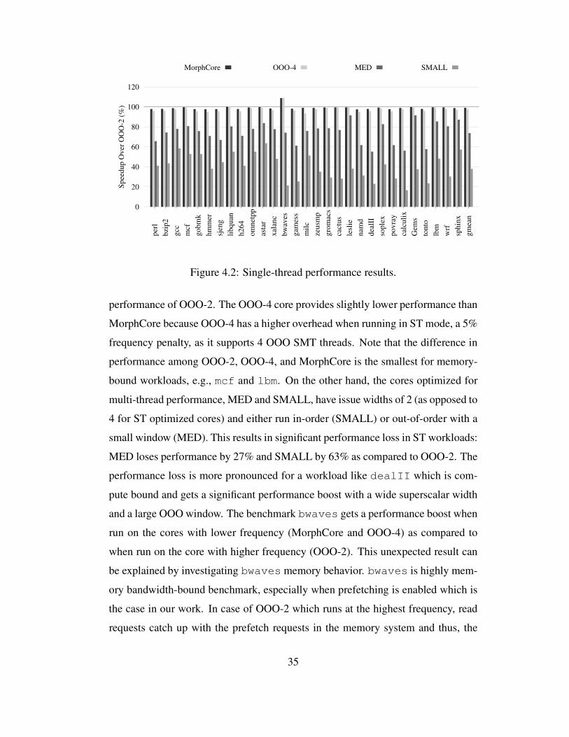
0
20
40
60
80
100
120
per
l
bzi
p2
gcc
mcf
go
bm
k
hm
mer
sjen
g
lib
qu
an
h2
64
om
net
pp
asta
r
xal
anc
bw
aves
gam
ess
mil
c
zeu
smp
gro
mac
s
cact
us
lesl
ie
nam
d
dea
lII
sop
lex
po
vra
y
calc
uli
x
Gem
s
ton
to
lbm
wrf
sph
inx
gm
ean
Sp
eed
up
Ov
er O
OO
-2 (
%)
MorphCore OOO-4 MED SMALL
Figure 4.2: Single-thread performance results.
performance of OOO-2. The OOO-4 core provides slightly lower performance than
MorphCore because OOO-4 has a higher overhead when running in ST mode, a 5%
frequency penalty, as it supports 4 OOO SMT threads. Note that the difference in
performance among OOO-2, OOO-4, and MorphCore is the smallest for memory-
bound workloads, e.g., mcf and lbm. On the other hand, the cores optimized for
multi-thread performance, MED and SMALL, have issue widths of 2 (as opposed to
4 for ST optimized cores) and either run in-order (SMALL) or out-of-order with a
small window (MED). This results in significant performance loss in ST workloads:
MED loses performance by 27% and SMALL by 63% as compared to OOO-2. The
performance loss is more pronounced for a workload like dealII which is com-
pute bound and gets a significant performance boost with a wide superscalar width
and a large OOO window. The benchmark bwaves gets a performance boost when
run on the cores with lower frequency (MorphCore and OOO-4) as compared to
when run on the core with higher frequency (OOO-2). This unexpected result can
be explained by investigating bwaves memory behavior. bwaves is highly mem-
ory bandwidth-bound benchmark, especially when prefetching is enabled which is
the case in our work. In case of OOO-2 which runs at the highest frequency, read
requests catch up with the prefetch requests in the memory system and thus, the
35
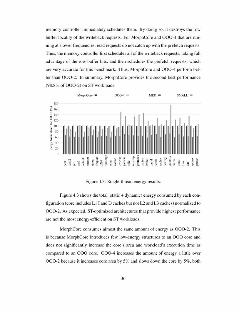
memory controller immediately schedules them. By doing so, it destroys the row
buffer locality of the writeback requests. For MorphCore and OOO-4 that are run-
ning at slower frequencies, read requests do not catch up with the prefetch requests.
Thus, the memory controller first schedules all of the writeback requests, taking full
advantage of the row buffer hits, and then schedules the prefetch requests, which
are very accurate for this benchmark. Thus, MorphCore and OOO-4 perform bet-
ter than OOO-2. In summary, MorphCore provides the second best performance
(98.8% of OOO-2) on ST workloads.
0
20
40
60
80
100
120
140
160
180
per
l
bzi
p2
gcc
mcf
go
bm
k
hm
mer
sjen
g
lib
qu
an
h2
64
om
net
pp
asta
r
xal
anc
bw
aves
gam
ess
mil
c
zeu
smp
gro
mac
s
cact
us
lesl
ie
nam
d
dea
lII
sop
lex
po
vra
y
calc
uli
x
Gem
s
ton
to
lbm
wrf
sph
inx
gm
ean
En
erg
y N
orm
aliz
ed t
o O
OO
-2 (
%)
MorphCore OOO-4 MED SMALL
Figure 4.3: Single-thread energy results.
Figure 4.3 shows the total (static + dynamic) energy consumed by each con-
figuration (core includes L1 I and D caches but not L2 and L3 caches) normalized to
OOO-2. As expected, ST-optimized architectures that provide highest performance
are not the most energy-efficient on ST workloads.
MorphCore consumes almost the same amount of energy as OOO-2. This
is because MorphCore introduces few low-energy structures to an OOO core and
does not significantly increase the core’s area and workload’s execution time as
compared to an OOO core. OOO-4 increases the amount of energy a little over
OOO-2 because it increases core area by 5% and slows down the core by 5%, both
36
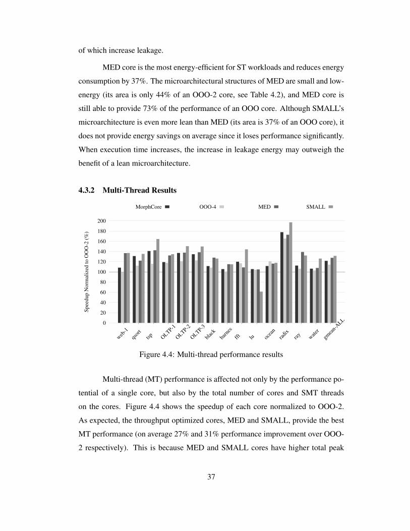
of which increase leakage.
MED core is the most energy-efficient for ST workloads and reduces energy
consumption by 37%. The microarchitectural structures of MED are small and low-
energy (its area is only 44% of an OOO-2 core, see Table 4.2), and MED core is
still able to provide 73% of the performance of an OOO core. Although SMALL’s
microarchitecture is even more lean than MED (its area is 37% of an OOO core), it
does not provide energy savings on average since it loses performance significantly.
When execution time increases, the increase in leakage energy may outweigh the
benefit of a lean microarchitecture.
4.3.2 Multi-Thread Results
0
20
40
60
80
100
120
140
160
180
200
web
-1
qsor
t
tsp
OLTP-1
OLTP-2
OLTP-3
blac
k
barn
es
fft
lu ocea
n
radi
xra
yw
ater
gmea
n-A
LL
Sp
eed
up
No
rmal
ized
to
OO
O-2
(%
)
MorphCore OOO-4 MED SMALL
Figure 4.4: Multi-thread performance results
Multi-thread (MT) performance is affected not only by the performance po-
tential of a single core, but also by the total number of cores and SMT threads
on the cores. Figure 4.4 shows the speedup of each core normalized to OOO-2.
As expected, the throughput optimized cores, MED and SMALL, provide the best
MT performance (on average 27% and 31% performance improvement over OOO-
2 respectively). This is because MED and SMALL cores have higher total peak
37
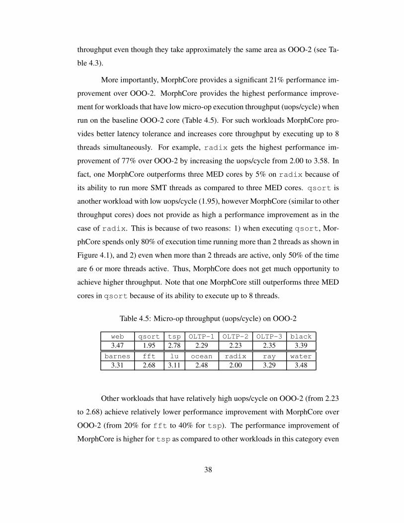
throughput even though they take approximately the same area as OOO-2 (see Ta-
ble 4.3).
More importantly, MorphCore provides a significant 21% performance im-
provement over OOO-2. MorphCore provides the highest performance improve-
ment for workloads that have low micro-op execution throughput (uops/cycle) when
run on the baseline OOO-2 core (Table 4.5). For such workloads MorphCore pro-
vides better latency tolerance and increases core throughput by executing up to 8
threads simultaneously. For example, radix gets the highest performance im-
provement of 77% over OOO-2 by increasing the uops/cycle from 2.00 to 3.58. In
fact, one MorphCore outperforms three MED cores by 5% on radix because of
its ability to run more SMT threads as compared to three MED cores. qsort is
another workload with low uops/cycle (1.95), however MorphCore (similar to other
throughput cores) does not provide as high a performance improvement as in the
case of radix. This is because of two reasons: 1) when executing qsort, Mor-
phCore spends only 80% of execution time running more than 2 threads as shown in
Figure 4.1), and 2) even when more than 2 threads are active, only 50% of the time
are 6 or more threads active. Thus, MorphCore does not get much opportunity to
achieve higher throughput. Note that one MorphCore still outperforms three MED
cores in qsort because of its ability to execute up to 8 threads.
Table 4.5: Micro-op throughput (uops/cycle) on OOO-2
web qsort tsp OLTP-1 OLTP-2 OLTP-3 black
3.47 1.95 2.78 2.29 2.23 2.35 3.39
barnes fft lu ocean radix ray water
3.31 2.68 3.11 2.48 2.00 3.29 3.48
Other workloads that have relatively high uops/cycle on OOO-2 (from 2.23
to 2.68) achieve relatively lower performance improvement with MorphCore over
OOO-2 (from 20% for fft to 40% for tsp). The performance improvement of
MorphCore is higher for tsp as compared to other workloads in this category even
38
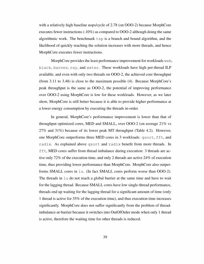
with a relatively high baseline uops/cycle of 2.78 (on OOO-2) because MorphCore
executes fewer instructions (-10%) as compared to OOO-2 although doing the same
algorithmic work. The benchmark tsp is a branch and bound algorithm, and the
likelihood of quickly reaching the solution increases with more threads, and hence
MorphCore executes fewer instructions.
MorphCore provides the least performance improvement for workloads web,
black, barnes, ray, and water. These workloads have high per-thread ILP
available, and even with only two threads on OOO-2, the achieved core throughput
(from 3.11 to 3.48) is close to the maximum possible (4). Because MorphCore’s
peak throughput is the same as OOO-2, the potential of improving performance
over OOO-2 using MorphCore is low for these workloads. However, as we later
show, MorphCore is still better because it is able to provide higher performance at
a lower energy consumption by executing the threads in-order.
In general, MorphCore’s performance improvement is lower than that of
throughput optimized cores, MED and SMALL, over OOO-2 (on average 21% vs
27% and 31%) because of its lower peak MT throughput (Table 4.2). However,
one MorphCore outperforms three MED cores in 3 workloads: qsort, fft, and
radix. As explained above qsort and radix benefit from more threads. In
fft, MED cores suffer from thread imbalance during execution: 3 threads are ac-
tive only 72% of the execution time, and only 2 threads are active 24% of execution
time, thus providing lower performance than MorphCore. MorphCore also outper-
forms SMALL cores in lu. (In fact SMALL cores perform worse than OOO-2).
The threads in lu do not reach a global barrier at the same time and have to wait
for the lagging thread. Because SMALL cores have low single-thread performance,
threads end up waiting for the lagging thread for a significant amount of time (only
1 thread is active for 35% of the execution time), and thus execution time increases
significantly. MorphCore does not suffer significantly from the problem of thread-
imbalance-at-barrier because it switches into OutOfOrder mode when only 1 thread
is active, therefore the waiting time for other threads is reduced.
39
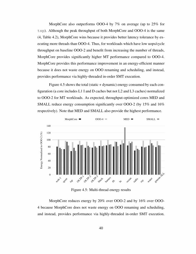
MorphCore also outperforms OOO-4 by 7% on average (up to 25% for
tsp). Although the peak throughput of both MorphCore and OOO-4 is the same
(4, Table 4.2), MorphCore wins because it provides better latency tolerance by ex-
ecuting more threads than OOO-4. Thus, for workloads which have low uops/cycle
throughput on baseline OOO-2 and benefit from increasing the number of threads,
MorphCore provides significantly higher MT performance compared to OOO-4.
MorphCore provides this performance improvement in an energy-efficient manner
because it does not waste energy on OOO renaming and scheduling, and instead,
provides performance via highly-threaded in-order SMT execution.
Figure 4.5 shows the total (static + dynamic) energy consumed by each con-
figuration (a core includes L1 I and D caches but not L2 and L3 caches) normalized
to OOO-2 for MT workloads. As expected, throughput-optimized cores MED and
SMALL reduce energy consumption significantly over OOO-2 (by 15% and 16%
respectively). Note that MED and SMALL also provide the highest performance.
0
20
40
60
80
100
120
140
web
-1
qsor
t
tsp
OLTP-1
OLTP-2
OLTP-3
blac
k
barn
es
fft
lu ocea
n
radi
xra
yw
ater
gmea
n-A
LL
En
erg
y N
orm
aliz
ed t
o O
OO
-2 (
%)
MorphCore OOO-4 MED SMALL
Figure 4.5: Multi-thread energy results
MorphCore reduces energy by 20% over OOO-2 and by 16% over OOO-
4 because MorphCore does not waste energy on OOO renaming and scheduling,
and instead, provides performance via highly-threaded in-order SMT execution.
40

MorphCore reduces energy consumption for two reasons: 1) MorphCore reduces
execution time, thus keeping the core’s structures active for a shorter period of time,
and 2) even when MorphCore is active, some of the structures that will be active
in traditional out-of-order cores will be inactive in MorphCore’s InOrder mode.
These structures include the Rename logic, part of the instruction Scheduler, and
the Load Queue. Figure 2.2 shows that the OOO structures contribute significantly
to the overall energy consumption, and if those structures can be turned off, while
providing performance through in-order SMT, significant performance and energy
savings can be obtained. We find that 50% of the energy savings of MorphCore
over OOO-2, and 75% of the energy savings of MorphCore over OOO-4 come
from reducing the activity of these structures.
4.3.3 Single-thread and Multi-thread Results Summary
On single-thread (ST) workloads, MorphCore performs very close to OOO-
2, the best ST-optimized architecture. On multi-thread (MT) workloads, Mor-
phCore performs 21% higher than OOO-2 while providing 20% energy savings over
OOO-2, and achieves 2/3 of the performance potential of the best MT-optimized ar-
chitectures (MED and SMALL),. We conclude that MorphCore is able to handle
diverse ST and MT workloads efficiently.
4.3.4 Sensitivity of MorphCore’s Results to Frequency Penalty
Figures 4.6 and 4.7 show how MorphCore’s performance and energy effi-
ciency changes with the frequency penalty (because of its adaptive design) as com-
pared to the OOO-2 core. We find that for a MorphCore with an x% frequency
penalty, performance of ST and MT workloads reduces by ∼ x/2% and x% respec-
tively as compared to a MorphCore with no frequency penalty. This is because our
ST workloads are core+memory bound while our MT workloads are primarily core
bound. For example, MorphCore with a 10% frequency penalty reduces perfor-
mance by 4% on ST workloads and 7% on MT workloads over MorphCore with a
2.5% frequency penalty. Because of the increase in execution time, MorphCore in-
41
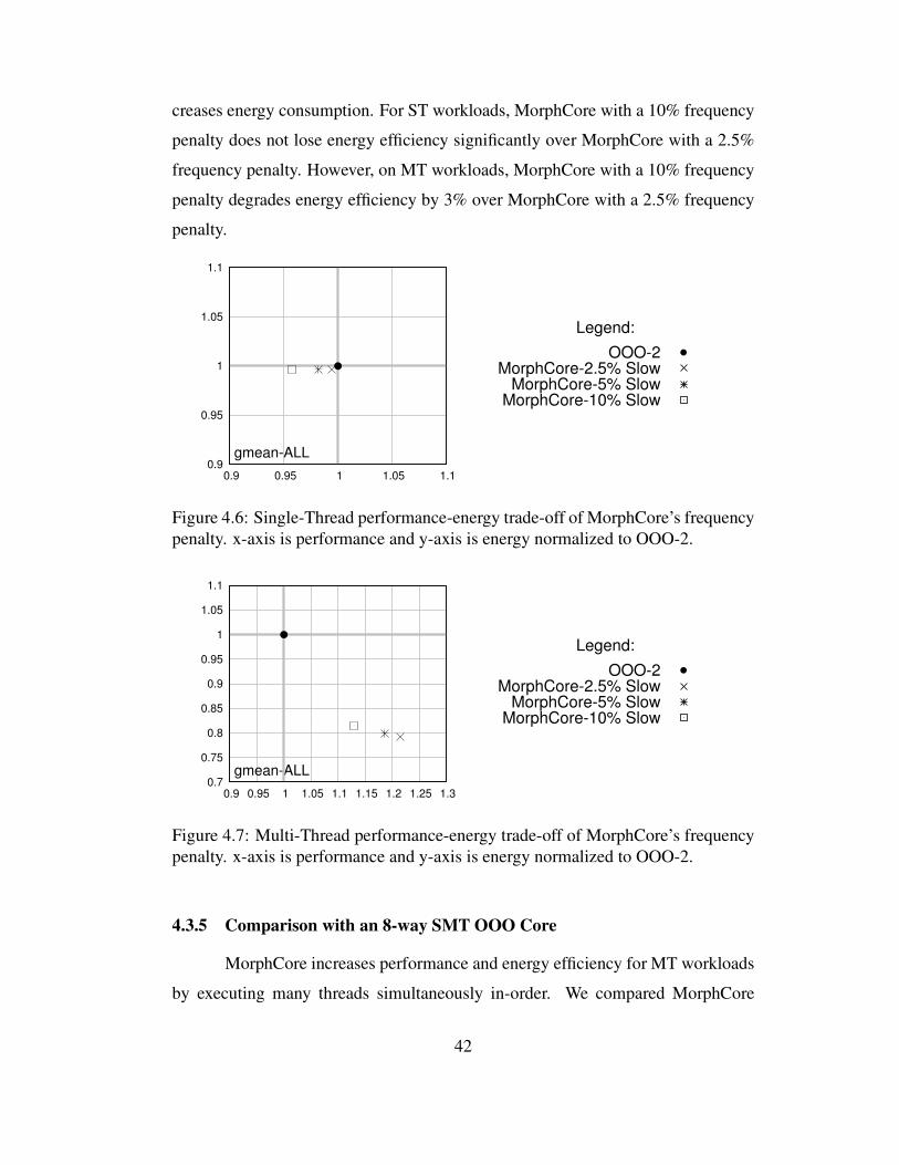
creases energy consumption. For ST workloads, MorphCore with a 10% frequency
penalty does not lose energy efficiency significantly over MorphCore with a 2.5%
frequency penalty. However, on MT workloads, MorphCore with a 10% frequency
penalty degrades energy efficiency by 3% over MorphCore with a 2.5% frequency
penalty.
0.9
0.95
1
1.05
1.1
0.9 0.95 1 1.05 1.1
gmean-ALL
Legend:
OOO-2MorphCore-2.5% Slow
MorphCore-5% SlowMorphCore-10% Slow
Figure 4.6: Single-Thread performance-energy trade-off of MorphCore’s frequency
penalty. x-axis is performance and y-axis is energy normalized to OOO-2.
0.7
0.75
0.8
0.85
0.9
0.95
1
1.05
1.1
0.9 0.95 1 1.05 1.1 1.15 1.2 1.25 1.3
gmean-ALL
Legend:
OOO-2MorphCore-2.5% Slow
MorphCore-5% SlowMorphCore-10% Slow
Figure 4.7: Multi-Thread performance-energy trade-off of MorphCore’s frequency
penalty. x-axis is performance and y-axis is energy normalized to OOO-2.
4.3.5 Comparison with an 8-way SMT OOO Core
MorphCore increases performance and energy efficiency for MT workloads
by executing many threads simultaneously in-order. We compared MorphCore
42
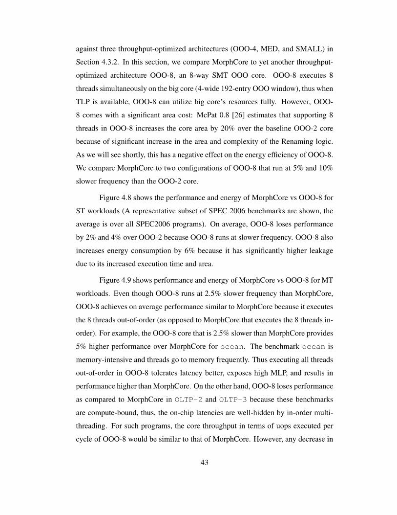
against three throughput-optimized architectures (OOO-4, MED, and SMALL) in
Section 4.3.2. In this section, we compare MorphCore to yet another throughput-
optimized architecture OOO-8, an 8-way SMT OOO core. OOO-8 executes 8
threads simultaneously on the big core (4-wide 192-entry OOO window), thus when
TLP is available, OOO-8 can utilize big core’s resources fully. However, OOO-
8 comes with a significant area cost: McPat 0.8 [26] estimates that supporting 8
threads in OOO-8 increases the core area by 20% over the baseline OOO-2 core
because of significant increase in the area and complexity of the Renaming logic.
As we will see shortly, this has a negative effect on the energy efficiency of OOO-8.
We compare MorphCore to two configurations of OOO-8 that run at 5% and 10%
slower frequency than the OOO-2 core.
Figure 4.8 shows the performance and energy of MorphCore vs OOO-8 for
ST workloads (A representative subset of SPEC 2006 benchmarks are shown, the
average is over all SPEC2006 programs). On average, OOO-8 loses performance
by 2% and 4% over OOO-2 because OOO-8 runs at slower frequency. OOO-8 also
increases energy consumption by 6% because it has significantly higher leakage
due to its increased execution time and area.
Figure 4.9 shows performance and energy of MorphCore vs OOO-8 for MT
workloads. Even though OOO-8 runs at 2.5% slower frequency than MorphCore,
OOO-8 achieves on average performance similar to MorphCore because it executes
the 8 threads out-of-order (as opposed to MorphCore that executes the 8 threads in-
order). For example, the OOO-8 core that is 2.5% slower than MorphCore provides
5% higher performance over MorphCore for ocean. The benchmark ocean is
memory-intensive and threads go to memory frequently. Thus executing all threads
out-of-order in OOO-8 tolerates latency better, exposes high MLP, and results in
performance higher than MorphCore. On the other hand, OOO-8 loses performance
as compared to MorphCore in OLTP-2 and OLTP-3 because these benchmarks
are compute-bound, thus, the on-chip latencies are well-hidden by in-order multi-
threading. For such programs, the core throughput in terms of uops executed per
cycle of OOO-8 would be similar to that of MorphCore. However, any decrease in
43

frequency of the core proportionally reduces its performance, and hence the reason
for reduced performance of OOO-8 compared to MorphCore.
A major benefit of MorphCore over OOO-8 is its energy efficiency: Mor-
phCore reduces energy consumption by 20% over OOO-2 whereas OOO-8 reduces
energy consumption by only 3%. MorphCore is more energy efficient than OOO-8
because it is able to achieve similarly high performance but with in-order SMT ex-
ecution and reduced area. We conclude that MorphCore is a better alternative for
improving performance and energy efficiency for MT workloads than OOO-8.
44
0
20
40
60
80
100
perl
bzip
2
mcf
hmm
er
libqu
antu
m
h264
asta
rxa
lanc
milc
zeus
mp
cact
us
deal
II
Gem
s
lbm
gmea
n-A
LL
Per
form
ance
norm
aliz
ed t
o O
OO
-2 c
ore
(%
)
MorphCore-2.5% slowOOO-8 5% slow
OOO-8 10% slow
(a) Performance
0
20
40
60
80
100
120
perl
bzip
2
mcf
hmm
er
libqu
antu
m
h264
asta
rxa
lanc
milc
zeus
mp
cact
us
deal
II
Gem
s
lbm
gmea
n-A
LLEner
gy n
orm
aliz
ed t
o O
OO
-2 c
ore
(%
)
(b) Energy
Figure 4.8: Single-Thread performance and energy of MorphCore vs. 8-way SMT
OOO core.
45
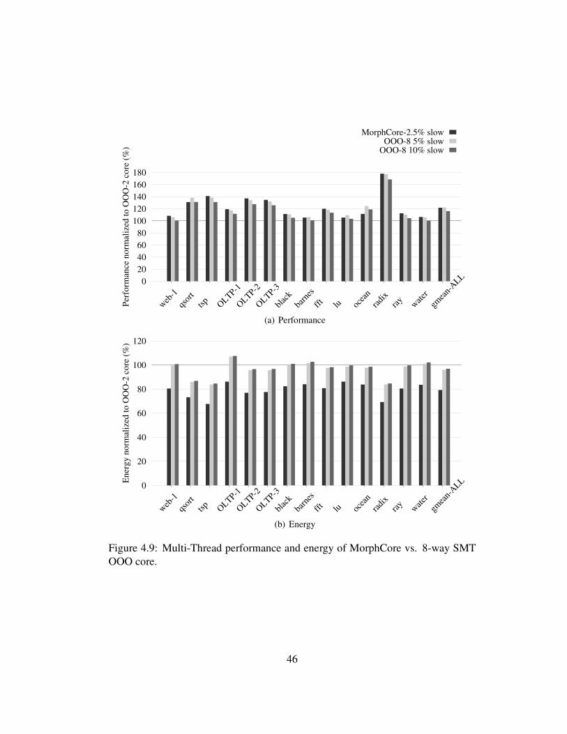
0
20
40
60
80
100
120
140
160
180
web
-1
qsor
t
tsp
OLTP-1
OLTP-2
OLTP-3
blac
k
barn
es
fft
lu ocea
n
radi
xra
yw
ater
gmea
n-A
LL
Per
form
ance
norm
aliz
ed t
o O
OO
-2 c
ore
(%
)MorphCore-2.5% slow
OOO-8 5% slowOOO-8 10% slow
(a) Performance
0
20
40
60
80
100
120
web
-1
qsor
t
tsp
OLTP-1
OLTP-2
OLTP-3
blac
k
barn
es
fft
lu ocea
n
radi
xra
yw
ater
gmea
n-A
LLEner
gy n
orm
aliz
ed t
o O
OO
-2 c
ore
(%
)
(b) Energy
Figure 4.9: Multi-Thread performance and energy of MorphCore vs. 8-way SMT
OOO core.
46
4.3.6 Effect of a Limited Capacity/Bandwidth Memory System
MorphCore improves throughput performance over OOO-2 by executing 8
threads simultaneously. This may increase capacity and bandwidth demands on the
memory system, and may hurt the performance of MorphCore in InOrder mode. To
show these effects, we evaluate the performance of the 3 most memory intensive
benchmarks from our MT workload suite, fft, ocean, and radix, for differ-
ent memory system configurations. For all memory system configurations, both
baseline OOO-2 and MorphCore simulations use the same configuration.
We first repeat our baseline results from Figure 4.4. Figure 4.10(a) shows
MorphCore’s performance for the three benchmarks over OOO-2 for the base-
line memory system. Our baseline memory system consists of a 2MB last-level
cache (LLC) and 2 DRAM channels where each channel has 8 banks. Table 4.1
shows detailed memory system parameters. Figure 4.10(b) shows that when the
DRAM channels are halved (from 2 to 1), MorphCore performance improvement
over OOO-2 reduces for all three benchmarks (the average reduces from 33% to
25%). When the number of channels are kept to 2, and the LLC size is reduced
from 2MB to 1MB in Figure 4.10(c), MorphCore’s performance improvement over
OOO-2 is not hurt significantly.
However, when both LLC size and the number of DRAM channels are re-
duced in Figure 4.11(a), MorphCore’s performance improvement is only 20% as
compared to 33% for the baseline memory system. More noticeably, MorphCore
reduces performance for ocean over OOO-2. This is because with a 1MB LLC,
8 threads put significant pressure on the LLC capacity and the miss rate increases
which increases the DRAM bandwidth demand. With only a single DRAM channel,
the bus contention and the DRAM bank interference increases which hurts perfor-
mance. OOO-2 does not experience such contention and interference because it
runs only 2 threads. To show that the decrease in ocean’s performance is because
of the significant DRAM row buffer and bank interference, we increase the number
of DRAM banks per channel to 16 in Figure 4.11(b) keeping the 1MB LLC size and
47
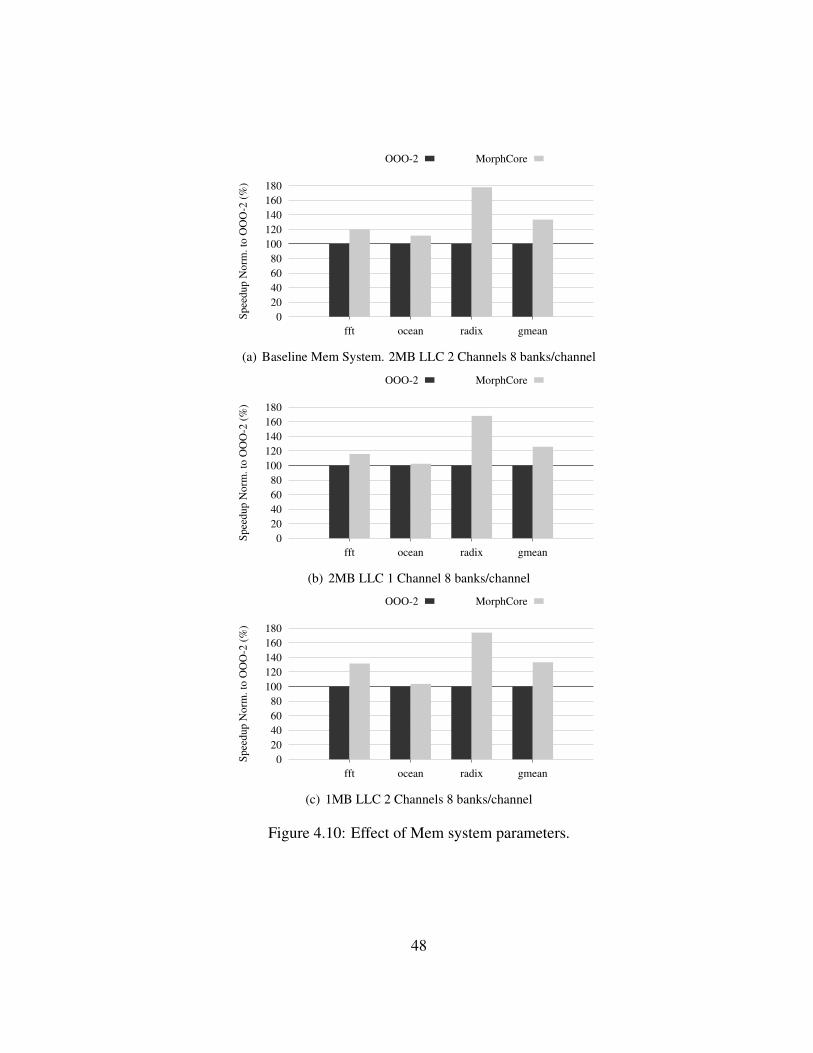
0
20
40
60
80
100
120
140
160
180
fft ocean radix gmean
Spee
dup N
orm
. to
OO
O-2
(%
)
OOO-2 MorphCore
(a) Baseline Mem System. 2MB LLC 2 Channels 8 banks/channel
0
20
40
60
80
100
120
140
160
180
fft ocean radix gmean
Spee
dup N
orm
. to
OO
O-2
(%
)
OOO-2 MorphCore
(b) 2MB LLC 1 Channel 8 banks/channel
0
20
40
60
80
100
120
140
160
180
fft ocean radix gmean
Spee
dup N
orm
. to
OO
O-2
(%
)
OOO-2 MorphCore
(c) 1MB LLC 2 Channels 8 banks/channel
Figure 4.10: Effect of Mem system parameters.
48
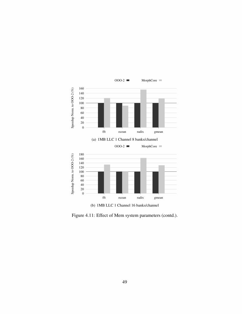
0
20
40
60
80
100
120
140
160
fft ocean radix gmean
Spee
dup N
orm
. to
OO
O-2
(%
)
OOO-2 MorphCore
(a) 1MB LLC 1 Channel 8 banks/channel
0
20
40
60
80
100
120
140
160
180
fft ocean radix gmean
Spee
dup N
orm
. to
OO
O-2
(%
)
OOO-2 MorphCore
(b) 1MB LLC 1 Channel 16 banks/channel
Figure 4.11: Effect of Mem system parameters (contd.).
49
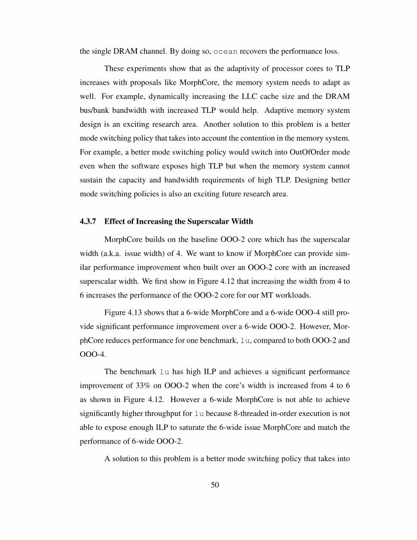
the single DRAM channel. By doing so, ocean recovers the performance loss.
These experiments show that as the adaptivity of processor cores to TLP
increases with proposals like MorphCore, the memory system needs to adapt as
well. For example, dynamically increasing the LLC cache size and the DRAM
bus/bank bandwidth with increased TLP would help. Adaptive memory system
design is an exciting research area. Another solution to this problem is a better
mode switching policy that takes into account the contention in the memory system.
For example, a better mode switching policy would switch into OutOfOrder mode
even when the software exposes high TLP but when the memory system cannot
sustain the capacity and bandwidth requirements of high TLP. Designing better
mode switching policies is also an exciting future research area.
4.3.7 Effect of Increasing the Superscalar Width
MorphCore builds on the baseline OOO-2 core which has the superscalar
width (a.k.a. issue width) of 4. We want to know if MorphCore can provide sim-
ilar performance improvement when built over an OOO-2 core with an increased
superscalar width. We first show in Figure 4.12 that increasing the width from 4 to
6 increases the performance of the OOO-2 core for our MT workloads.
Figure 4.13 shows that a 6-wide MorphCore and a 6-wide OOO-4 still pro-
vide significant performance improvement over a 6-wide OOO-2. However, Mor-
phCore reduces performance for one benchmark, lu, compared to both OOO-2 and
OOO-4.
The benchmark lu has high ILP and achieves a significant performance
improvement of 33% on OOO-2 when the core’s width is increased from 4 to 6
as shown in Figure 4.12. However a 6-wide MorphCore is not able to achieve
significantly higher throughput for lu because 8-threaded in-order execution is not
able to expose enough ILP to saturate the 6-wide issue MorphCore and match the
performance of 6-wide OOO-2.
A solution to this problem is a better mode switching policy that takes into
50
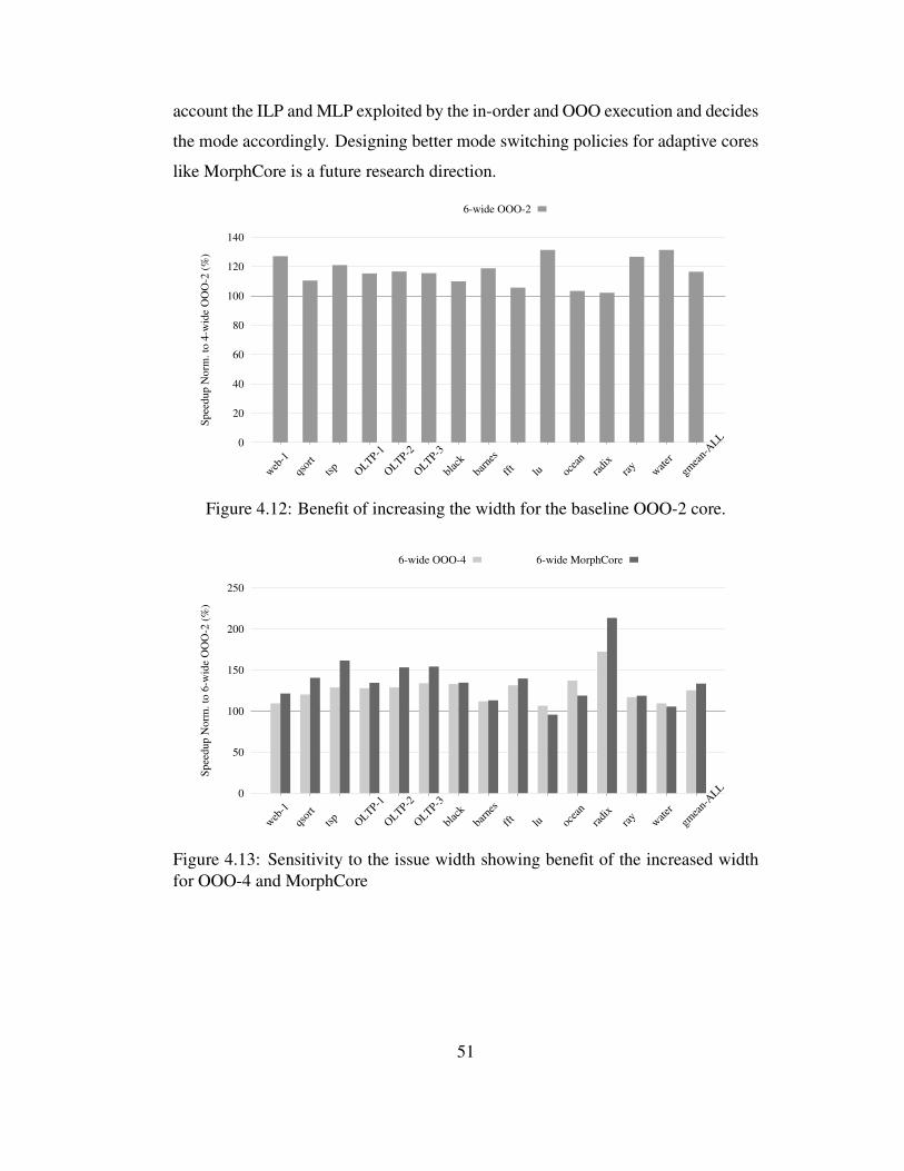
account the ILP and MLP exploited by the in-order and OOO execution and decides
the mode accordingly. Designing better mode switching policies for adaptive cores
like MorphCore is a future research direction.
0
20
40
60
80
100
120
140
web
-1
qsor
t
tsp
OLTP-1
OLTP-2
OLTP-3
blac
k
barn
es
fft
lu ocea
n
radi
xra
yw
ater
gmea
n-A
LL
Spee
dup N
orm
. to
4-w
ide
OO
O-2
(%
)6-wide OOO-2
Figure 4.12: Benefit of increasing the width for the baseline OOO-2 core.
0
50
100
150
200
250
web
-1
qsor
t
tsp
OLTP-1
OLTP-2
OLTP-3
blac
k
barn
es
fft
lu ocea
n
radi
xra
yw
ater
gmea
n-A
LL
Spee
dup N
orm
. to
6-w
ide
OO
O-2
(%
)
6-wide OOO-4 6-wide MorphCore
Figure 4.13: Sensitivity to the issue width showing benefit of the increased width
for OOO-4 and MorphCore
51
Chapter 5
Adapting to Instruction-Level Parallelism (ILP) and
Memory-Level Parallelism (MLP)
In Sections 2.3.2 and 2.3.3, I showed a high-level design of MorphCore
that dynamically varies both superscalar width and out-of-order window size of
the core to adapt to Instruction-Level Parallelism (ILP) and Memory-Level Paral-
lelism (MLP) present in the single-thread programs. In this chapter, I will present
the detailed microarchitecture of MorphCore for doing so. Note that our proposed
MorphCore design operates as an out-of-order core when it adapts to ILP and MLP,
even though the microarchitecture supports in-order execution (via InOrder mode
when TLP is available). An obvious option for low-power and perhaps for low-
energy operation is a single-threaded in-order mode. We call this mode InOrder-ST
Mode. We have designed and investigated the InOrder-ST mode with the goal of
providing energy savings. We first describe a high-level architecture of InOrder-
ST Mode. We then evaluate the performance and energy of the InOrder-ST Mode
and show that InOrder-ST mode in fact does not save energy as compared to the
OutOfOrder mode.
5.1 InOrder Mode for Single-threaded Programs
The InOrder-ST Mode executes a single-thread program. It turns off all ad-
ditional structures required for multi-threading (e.g. multiple PCs). Like the multi-
thread InOrder mode, it turns off OOO-renaming, OOO-scheduling, and load/store
queue lookups to save energy, and turns on a simple in-order renaming and in-order
scheduling logic. To further save energy, InOrder-ST mode also turns off parts of
the structures that are not used in single-thread in-order execution, reducing per-
52

access energy of these structures. We describe in detail how OOO execution struc-
tures can be partially turned off in Section 5.2. These structures include the Phys-
ical Register File (PRF), Reservation Stations (RS), ROB, and Load/Store Queue
(LSQ). Only a small portion of the PRF is required in order to store the architec-
tural state of the thread, the rest of the PRF is turned off. For RS and ROB, only a
small portion is needed to be ON since scheduling is constrained to the head of the
sequential instruction stream. For the LSQ, some of the entries are ON since they
are used as Store Buffer entries holding data waiting to be written into the d-cache.
InOrder-ST mode also reduces the width of the core. Each of the fetch-,
decode-, rename-, schedule-, execute-, and commit-width is reduced from 4- to 2-
instructions per cycle (we describe in detail how this is done in Section 5.2). At a
high level, for each pipeline stage in the core, half of the latches and the associated
clock delivery network is turned off, reducing the throughput of the pipeline by half.
This reduces both static and dynamic energy associated with clock and pipeline
latches. Note that the dynamic energy spent on doing the useful work per instruction
(e.g. to decode and execute an instruction) remains the same.
5.1.1 Problem: Poor Energy Efficiency
Figure 5.1 shows the performance-energy trade-off of MorphCore always
operating in InOrder-ST mode (2-wide in-order) and MorphCore always operating
in OutofOrder mode (4-wide 192-entry ROB OOO). Our performance simulation
parameters and energy estimation methodology (using a modified version of Mc-
PAT [26]) is presented in Section 6.4. The InOrder-ST mode loses 60% perfor-
mance and increases energy consumption by 30%. It may come as a surprise at
first that the InOrder-ST mode increases energy, since there are a number of energy
savings features incorporated in its design. However, because of in-order execu-
tion, the core loses a significant amount of performance. As the execution time
increases, both leakage energy and dynamic energy increase (the dynamic energy
increases due to increased clock activity). In the case of InOrder-ST, the increase
in energy due to a significant increase in execution time far outweighs the energy
53
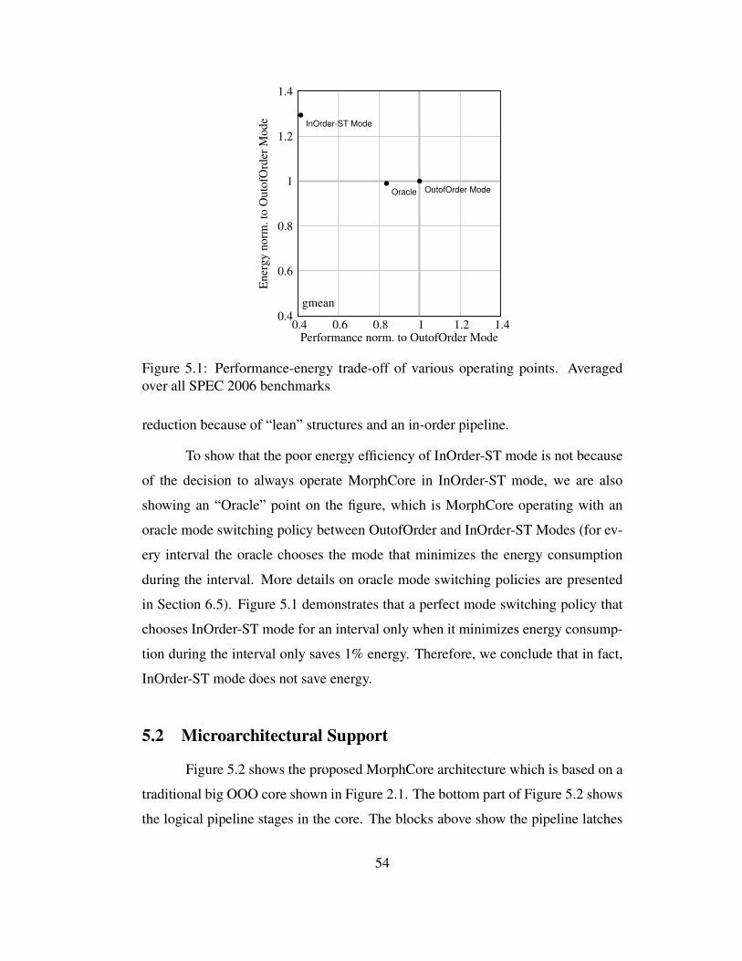
0.4
0.6
0.8
1
1.2
1.4
0.4 0.6 0.8 1 1.2 1.4
Ener
gy n
orm
. to
Outo
fOrd
er M
ode
Performance norm. to OutofOrder Mode
gmean
OutofOrder Mode
InOrder-ST Mode
Oracle
Figure 5.1: Performance-energy trade-off of various operating points. Averaged
over all SPEC 2006 benchmarks
reduction because of “lean” structures and an in-order pipeline.
To show that the poor energy efficiency of InOrder-ST mode is not because
of the decision to always operate MorphCore in InOrder-ST mode, we are also
showing an “Oracle” point on the figure, which is MorphCore operating with an
oracle mode switching policy between OutofOrder and InOrder-ST Modes (for ev-
ery interval the oracle chooses the mode that minimizes the energy consumption
during the interval. More details on oracle mode switching policies are presented
in Section 6.5). Figure 5.1 demonstrates that a perfect mode switching policy that
chooses InOrder-ST mode for an interval only when it minimizes energy consump-
tion during the interval only saves 1% energy. Therefore, we conclude that in fact,
InOrder-ST mode does not save energy.
5.2 Microarchitectural Support
Figure 5.2 shows the proposed MorphCore architecture which is based on a
traditional big OOO core shown in Figure 2.1. The bottom part of Figure 5.2 shows
the logical pipeline stages in the core. The blocks above show the pipeline latches
54
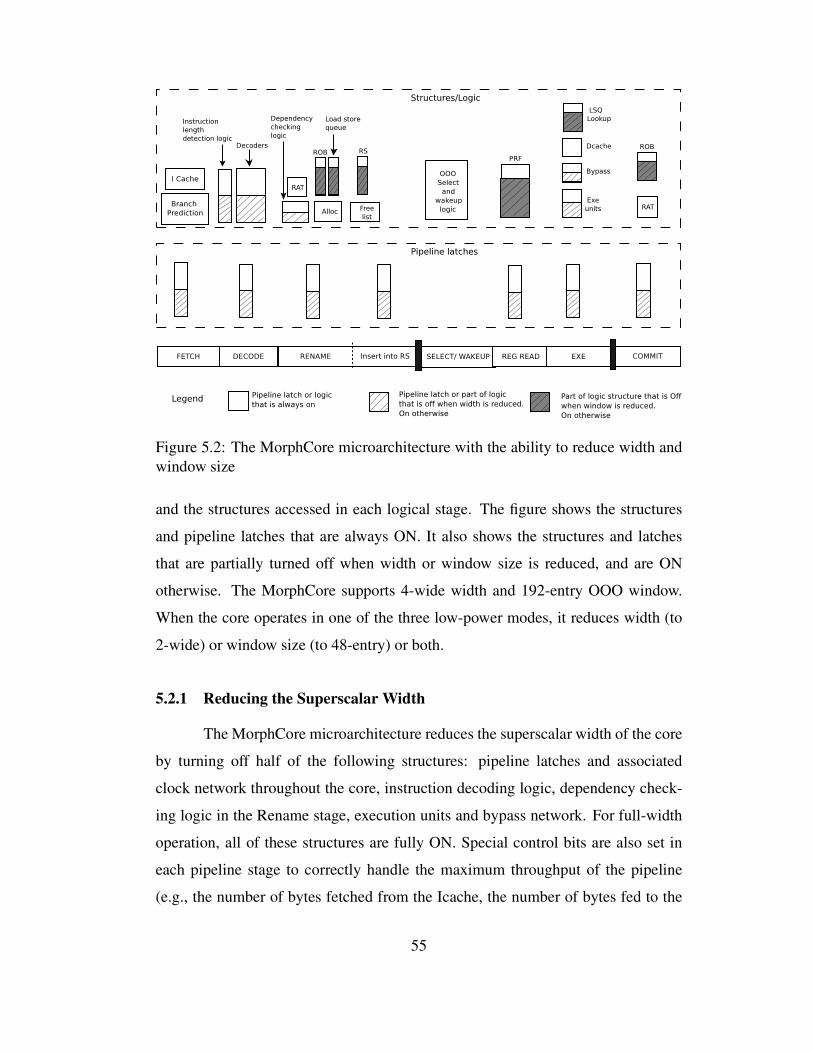
Figure 5.2: The MorphCore microarchitecture with the ability to reduce width and
window size
and the structures accessed in each logical stage. The figure shows the structures
and pipeline latches that are always ON. It also shows the structures and latches
that are partially turned off when width or window size is reduced, and are ON
otherwise. The MorphCore supports 4-wide width and 192-entry OOO window.
When the core operates in one of the three low-power modes, it reduces width (to
2-wide) or window size (to 48-entry) or both.
5.2.1 Reducing the Superscalar Width
The MorphCore microarchitecture reduces the superscalar width of the core
by turning off half of the following structures: pipeline latches and associated
clock network throughout the core, instruction decoding logic, dependency check-
ing logic in the Rename stage, execution units and bypass network. For full-width
operation, all of these structures are fully ON. Special control bits are also set in
each pipeline stage to correctly handle the maximum throughput of the pipeline
(e.g., the number of bytes fetched from the Icache, the number of bytes fed to the
55
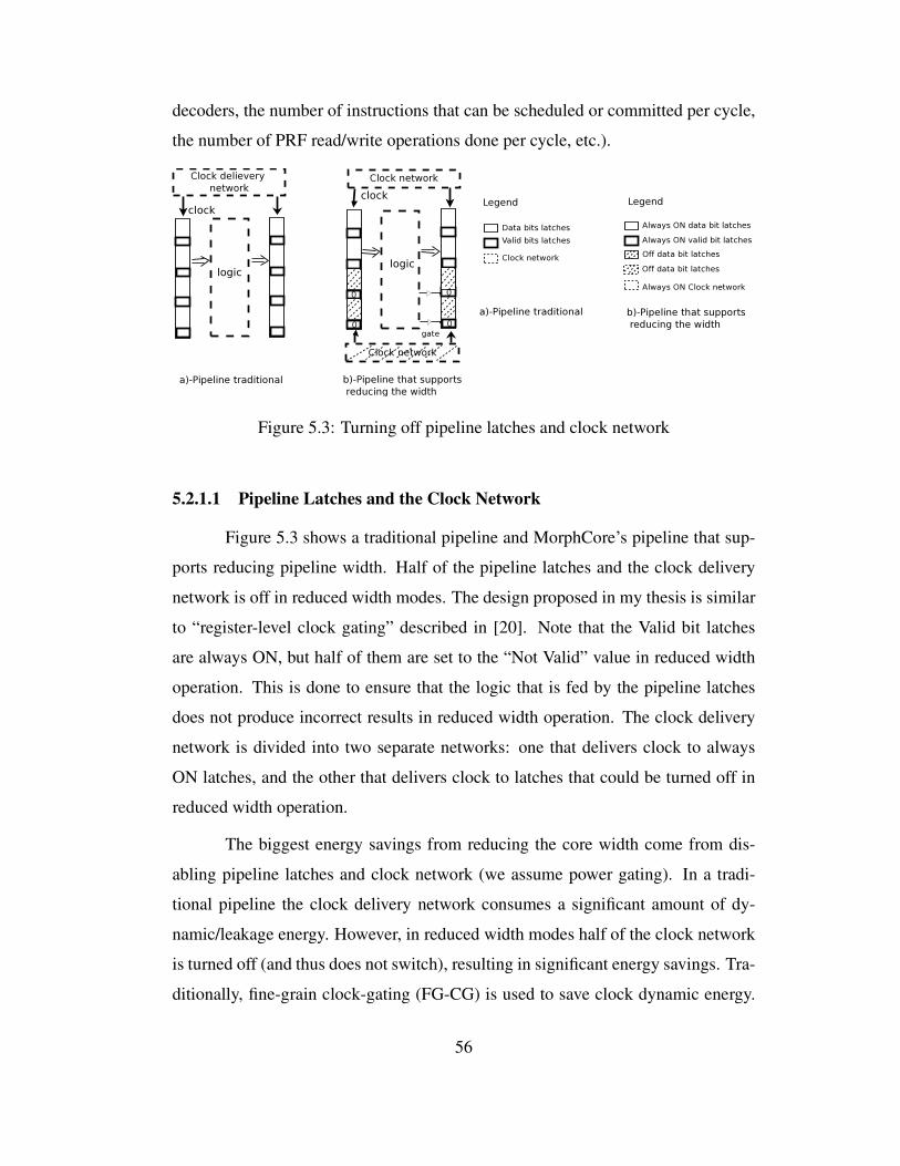
decoders, the number of instructions that can be scheduled or committed per cycle,
the number of PRF read/write operations done per cycle, etc.).
Figure 5.3: Turning off pipeline latches and clock network
5.2.1.1 Pipeline Latches and the Clock Network
Figure 5.3 shows a traditional pipeline and MorphCore’s pipeline that sup-
ports reducing pipeline width. Half of the pipeline latches and the clock delivery
network is off in reduced width modes. The design proposed in my thesis is similar
to “register-level clock gating” described in [20]. Note that the Valid bit latches
are always ON, but half of them are set to the “Not Valid” value in reduced width
operation. This is done to ensure that the logic that is fed by the pipeline latches
does not produce incorrect results in reduced width operation. The clock delivery
network is divided into two separate networks: one that delivers clock to always
ON latches, and the other that delivers clock to latches that could be turned off in
reduced width operation.
The biggest energy savings from reducing the core width come from dis-
abling pipeline latches and clock network (we assume power gating). In a tradi-
tional pipeline the clock delivery network consumes a significant amount of dy-
namic/leakage energy. However, in reduced width modes half of the clock network
is turned off (and thus does not switch), resulting in significant energy savings. Tra-
ditionally, fine-grain clock-gating (FG-CG) is used to save clock dynamic energy.
56
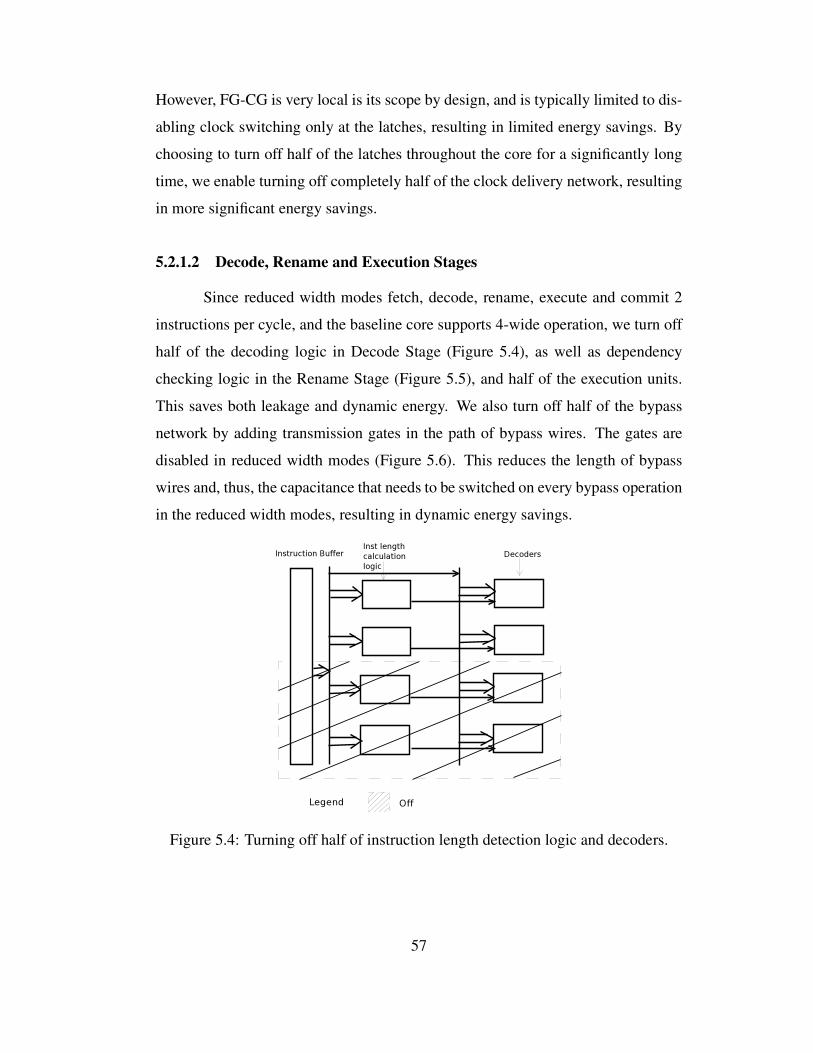
However, FG-CG is very local is its scope by design, and is typically limited to dis-
abling clock switching only at the latches, resulting in limited energy savings. By
choosing to turn off half of the latches throughout the core for a significantly long
time, we enable turning off completely half of the clock delivery network, resulting
in more significant energy savings.
5.2.1.2 Decode, Rename and Execution Stages
Since reduced width modes fetch, decode, rename, execute and commit 2
instructions per cycle, and the baseline core supports 4-wide operation, we turn off
half of the decoding logic in Decode Stage (Figure 5.4), as well as dependency
checking logic in the Rename Stage (Figure 5.5), and half of the execution units.
This saves both leakage and dynamic energy. We also turn off half of the bypass
network by adding transmission gates in the path of bypass wires. The gates are
disabled in reduced width modes (Figure 5.6). This reduces the length of bypass
wires and, thus, the capacitance that needs to be switched on every bypass operation
in the reduced width modes, resulting in dynamic energy savings.
Figure 5.4: Turning off half of instruction length detection logic and decoders.
57
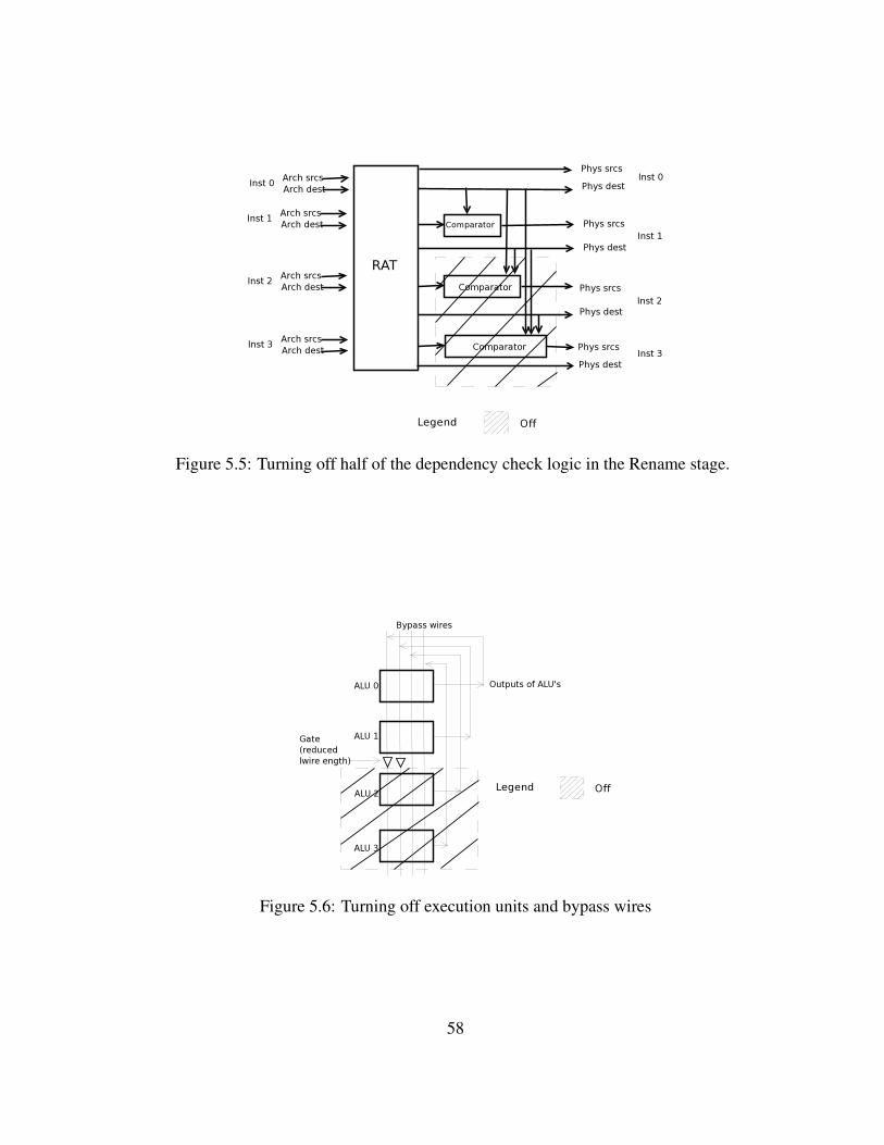
Figure 5.5: Turning off half of the dependency check logic in the Rename stage.
Figure 5.6: Turning off execution units and bypass wires
58
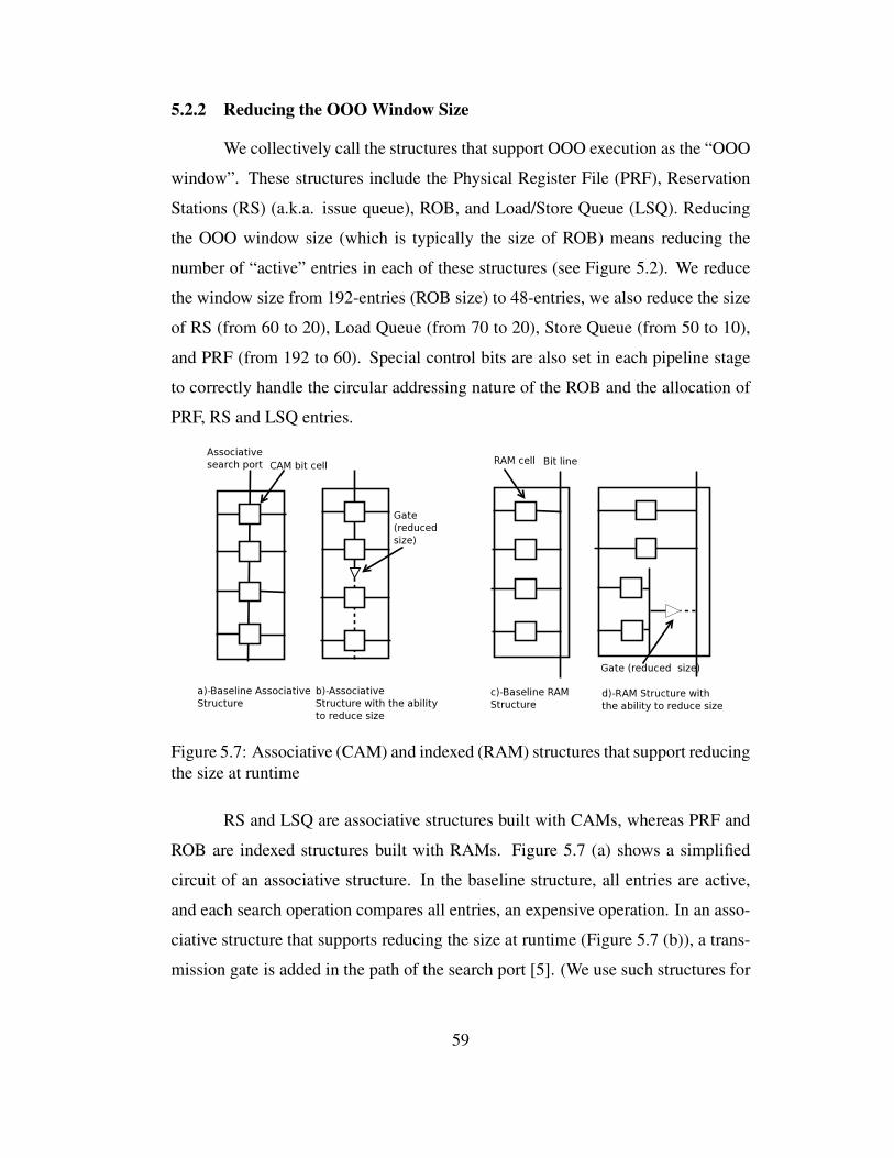
5.2.2 Reducing the OOO Window Size
We collectively call the structures that support OOO execution as the “OOO
window”. These structures include the Physical Register File (PRF), Reservation
Stations (RS) (a.k.a. issue queue), ROB, and Load/Store Queue (LSQ). Reducing
the OOO window size (which is typically the size of ROB) means reducing the
number of “active” entries in each of these structures (see Figure 5.2). We reduce
the window size from 192-entries (ROB size) to 48-entries, we also reduce the size
of RS (from 60 to 20), Load Queue (from 70 to 20), Store Queue (from 50 to 10),
and PRF (from 192 to 60). Special control bits are also set in each pipeline stage
to correctly handle the circular addressing nature of the ROB and the allocation of
PRF, RS and LSQ entries.
Figure 5.7: Associative (CAM) and indexed (RAM) structures that support reducing
the size at runtime
RS and LSQ are associative structures built with CAMs, whereas PRF and
ROB are indexed structures built with RAMs. Figure 5.7 (a) shows a simplified
circuit of an associative structure. In the baseline structure, all entries are active,
and each search operation compares all entries, an expensive operation. In an asso-
ciative structure that supports reducing the size at runtime (Figure 5.7 (b)), a trans-
mission gate is added in the path of the search port [5]. (We use such structures for
59

RS and LSQ). When the window size is reduced, the gate is disabled, reducing the
number of entries that a search operation needs to compare, reducing energy per
search operation.
Figure 5.7 (c) shows a simplified circuit of a RAM structure. In the base-
line structure, all RAM cells put capacitive load on the bit line, and thus, each
pre-charging/dis-charging of the bitline is an expensive operation (especially for
large multi-ported structures). A RAM structure that supports reducing the size at
runtime (Figure 5.7 (d)) uses a circuit technique called bitline segmentation which
was proposed and evaluated using circuit simulations by [9, 5] . In this technique,
the cells that could be disabled are connected to a local bitline which is then con-
nected to the main bitline through a buffer. The buffer is turned off during reduced
size operation, taking away a significant capacitive load from the bitline, and thus,
reducing energy per access.
60
Chapter 6
Mode Switching Policy for Adapting to ILP/MLP and
Evaluation
MorphCore supports five modes: a highly-threaded in-order SMT mode,
and four out-of-order modes with different widths and window sizes. In Chapter 5,
I described the four out-of-order modes of the MorphCore microarchitecture that
are obtained by varying the superscalar width and the out-of-order window size. In
this chapter, I describe the switching policy that the MorphCore microarchitecture
uses to switch between these four operating modes to adapt to ILP/MLP present in
single-thread programs.
6.1 MorphCore Procedure for Changing Modes
Mode switching is handled by a micro-code routine. The micro code routine
drains the core pipeline including the Store Buffer. When changing the width of the
core, it turns OFF or turns ON the structures mentioned in Section 5.2.1, and sets
the control bits in each pipeline stage accordingly.
When reducing the window size, a large portion of the Physical Register
File (PRF) will be disabled. Thus, the micro-code routine re-maps and moves the
architectural registers currently mapped to soon-to-be-disabled PRF entries to the
PRF entries in the ON partition. On increasing the window size, this operation is
not needed. The micro-code routine then turns OFF or turns ON the structures men-
tioned in Section 5.2.2, and sets the control bits in each pipeline stage accordingly.
After the micro-code routine is complete, MorphCore resumes normal execution.
61
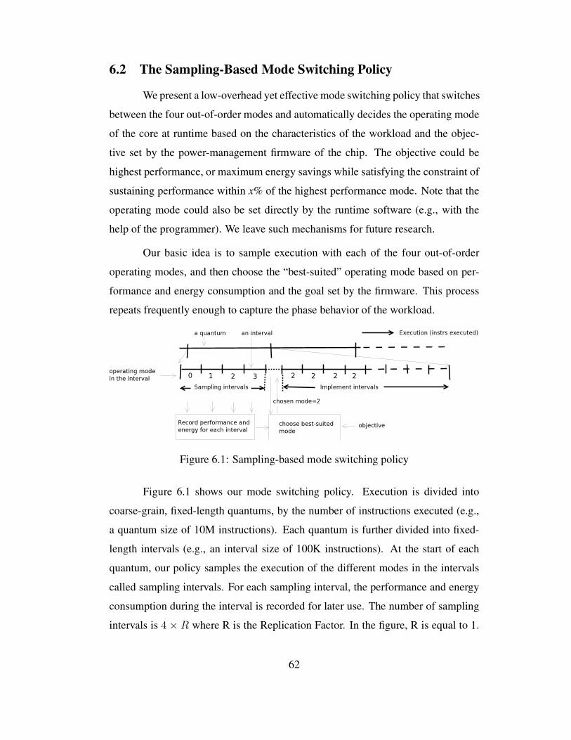
6.2 The Sampling-Based Mode Switching Policy
We present a low-overhead yet effective mode switching policy that switches
between the four out-of-order modes and automatically decides the operating mode
of the core at runtime based on the characteristics of the workload and the objec-
tive set by the power-management firmware of the chip. The objective could be
highest performance, or maximum energy savings while satisfying the constraint of
sustaining performance within x% of the highest performance mode. Note that the
operating mode could also be set directly by the runtime software (e.g., with the
help of the programmer). We leave such mechanisms for future research.
Our basic idea is to sample execution with each of the four out-of-order
operating modes, and then choose the “best-suited” operating mode based on per-
formance and energy consumption and the goal set by the firmware. This process
repeats frequently enough to capture the phase behavior of the workload.
Figure 6.1: Sampling-based mode switching policy
Figure 6.1 shows our mode switching policy. Execution is divided into
coarse-grain, fixed-length quantums, by the number of instructions executed (e.g.,
a quantum size of 10M instructions). Each quantum is further divided into fixed-
length intervals (e.g., an interval size of 100K instructions). At the start of each
quantum, our policy samples the execution of the different modes in the intervals
called sampling intervals. For each sampling interval, the performance and energy
consumption during the interval is recorded for later use. The number of sampling
intervals is 4 × R where R is the Replication Factor. In the figure, R is equal to 1.
62
A value of R equal to r means that each mode is sampled r times, and the perfor-
mance and energy consumption of the sampled execution of the mode will be the
average of r intervals. At the end of sampling intervals, a small firmware routine
is called. This routine chooses the “best-suited” mode based on the data collected
during the sampling intervals and the objective set by the chip firmware. For ex-
ample, if the objective is highest performance (or lowest energy), the mode with
highest performance (or lowest energy) during the sampled execution is chosen. If
the objective is lowest energy while satisfying the constraint of performance within
x% of the highest performance mode, the firmware routine sorts the sampled modes
by their energies consumed, and chooses the lowest energy mode that satisfies the
performance constraint. The core is then operated in the chosen mode for the rest
of the intervals in the quantum. We like to note here that we use the performance
loss constraint on energy savings in our policy as a “knob” to control the time spent
(and instructions executed) in low-power modes.
The effectiveness of the mode switching policy depends on the choice of
quantum size, interval size, and the Replication Factor. The size of the quantum
should be small enough to capture the workload phase behavior, and large enough
to amortize the overhead of sampling. Likewise the size of the sampling inter-
val should be large enough to capture the current “representative” behavior of the
workload and to average the bursty performance events (e.g., a burst of last-level
cache misses, or a burst of compute-intensive or memory-intensive instructions
etc.). Replicated Sampling is another method to average the bursty behavior. How-
ever, the sampling overhead increases with the size of the sampling interval and
with the Replication Factor. We experimented with different quantum and interval
sizes as well as with different replication factors, and based on the results of those
experiments, we have found that a quantum size of 10M instructions, an interval
size of 100K instructions, and a Replication Factor of 1 performs the best for our
simulation configurations and workloads.
63

6.3 Other Mode Switching Policies
In this section, I describe other mode switching policies that I designed and
evaluated, and also why they do not work.
6.3.1 Performance-stats based policies
The mode switching decision can be based on performance statistics such as
instructions issued per cycle, the amount of memory-level parallelism, the number
of branch mispredictions, etc.
6.3.1.1 Determining the window size based on MLP
A policy that makes decisions to increase or decrease the window size based
on the number of parallel memory requests seems to be a good policy at first. How-
ever, this policy does not work in practice for many workloads because a big win-
dow is not only needed for exposing parallel memory/DRAM requests, but also
needed when instructions have medium latencies (e.g., last level cache hits and
their dependents) or when the dependencies between instructions are such that a
big window is needed to expose ILP. Note that when a big window is needed to
expose ILP, a big width is needed as well, even though the absolute instructions
committed per cycle would still be small.
6.3.1.2 Determining the width based on instructions issued per cycle
This policy makes decisions to increase (or decrease) the width of the core
when the number of instructions issued (not committed) per cycle is above a threshold-
1 (or below a threshold-2). This policy works well when the window size is max-
imum. However, when window size is not maximum, this policy makes wrong
decisions because it can incorrectly decrease the width of the core just because the
observed instructions issued per cycle was below threshold-2 (instructions issued
per cycle is only below threshold-2 because of the small window size, and it may
not remain below threshold-2 with a big window size).
64

6.3.1.3 Determining the width and window size based on branch mispredic-
tions
This policy reduces the window size of the core when the number of branch
mispredictions per thousand instructions is above a threshold. The rationale is that
since branch mispredictions are frequent, a big window is not useful because it gets
filled with mostly wrong-path instructions. However, in practice this policy does
not work across the board because capturing only average behavior of branch mis-
predictions is not enough (the threshold changes between different workloads) and
other factors need to be considered as well, e.g., how much memory-level paral-
lelism and ILP gets exposed with big window.
Another policy I considered was to increase the width of the core to maxi-
mum when the core starts fetching instructions from the correct path after a branch
misprediction. The rationale here is that since the core needs to fill the pipeline,
it should start fetching at full rate. However, the performance benefit might not be
there because of the inherent dependencies between the instructions.
6.3.1.4 Determining the window size based on ROB and RS occupation
This policy increases (or decreases) the window size when the number of
entries occupied in ROB and RS is above a threshold-1 (or below a threshold-2).
However, simply looking at the occupation is not enough, and the performance
benefit of more instructions in ROB and RS needs to be taken into account.
6.3.2 Reducing the Overhead of Sampling with Signature-based Policies
The general idea of sampling the modes and then picking the best suited
mode for the current phase of the workload is appealing. An improvement to the
basic idea is to sample once and remember the best suited mode for the particular
phase. The hardware then continuously monitors the program characteristics, and
when a previously seen phase is encountered, the previously selected best suited
mode is executed next. An important ingredient of this policy is how to characterize
65
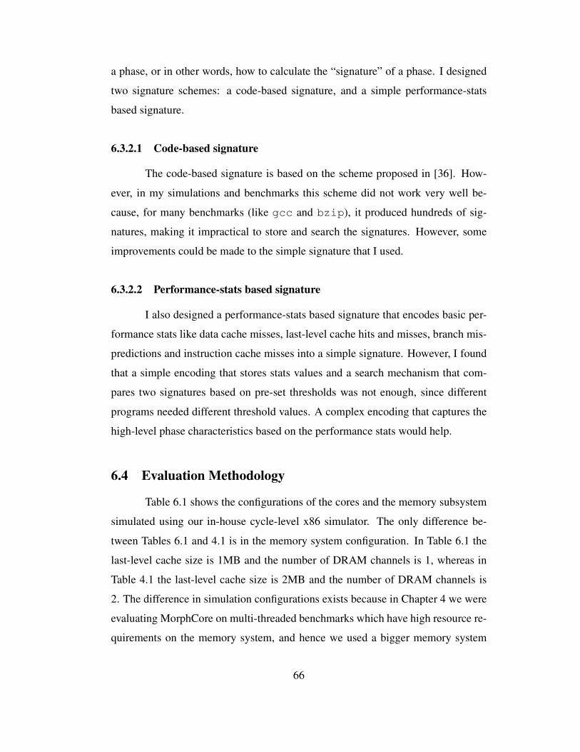
a phase, or in other words, how to calculate the “signature” of a phase. I designed
two signature schemes: a code-based signature, and a simple performance-stats
based signature.
6.3.2.1 Code-based signature
The code-based signature is based on the scheme proposed in [36]. How-
ever, in my simulations and benchmarks this scheme did not work very well be-
cause, for many benchmarks (like gcc and bzip), it produced hundreds of sig-
natures, making it impractical to store and search the signatures. However, some
improvements could be made to the simple signature that I used.
6.3.2.2 Performance-stats based signature
I also designed a performance-stats based signature that encodes basic per-
formance stats like data cache misses, last-level cache hits and misses, branch mis-
predictions and instruction cache misses into a simple signature. However, I found
that a simple encoding that stores stats values and a search mechanism that com-
pares two signatures based on pre-set thresholds was not enough, since different
programs needed different threshold values. A complex encoding that captures the
high-level phase characteristics based on the performance stats would help.
6.4 Evaluation Methodology
Table 6.1 shows the configurations of the cores and the memory subsystem
simulated using our in-house cycle-level x86 simulator. The only difference be-
tween Tables 6.1 and 4.1 is in the memory system configuration. In Table 6.1 the
last-level cache size is 1MB and the number of DRAM channels is 1, whereas in
Table 4.1 the last-level cache size is 2MB and the number of DRAM channels is
2. The difference in simulation configurations exists because in Chapter 4 we were
evaluating MorphCore on multi-threaded benchmarks which have high resource re-
quirements on the memory system, and hence we used a bigger memory system
66
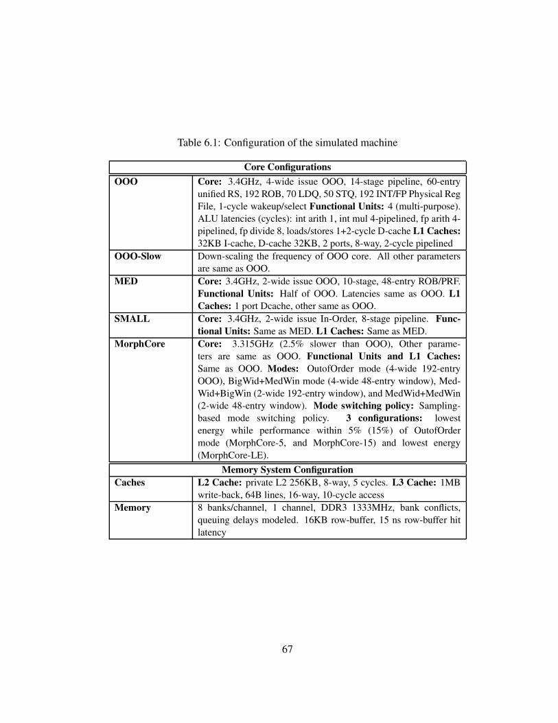
Table 6.1: Configuration of the simulated machine
Core Configurations
OOO Core: 3.4GHz, 4-wide issue OOO, 14-stage pipeline, 60-entry
unified RS, 192 ROB, 70 LDQ, 50 STQ, 192 INT/FP Physical Reg
File, 1-cycle wakeup/select Functional Units: 4 (multi-purpose).
ALU latencies (cycles): int arith 1, int mul 4-pipelined, fp arith 4-
pipelined, fp divide 8, loads/stores 1+2-cycle D-cache L1 Caches:
32KB I-cache, D-cache 32KB, 2 ports, 8-way, 2-cycle pipelined
OOO-Slow Down-scaling the frequency of OOO core. All other parameters
are same as OOO.
MED Core: 3.4GHz, 2-wide issue OOO, 10-stage, 48-entry ROB/PRF.
Functional Units: Half of OOO. Latencies same as OOO. L1
Caches: 1 port Dcache, other same as OOO.
SMALL Core: 3.4GHz, 2-wide issue In-Order, 8-stage pipeline. Func-
tional Units: Same as MED. L1 Caches: Same as MED.
MorphCore Core: 3.315GHz (2.5% slower than OOO), Other parame-
ters are same as OOO. Functional Units and L1 Caches:
Same as OOO. Modes: OutofOrder mode (4-wide 192-entry
OOO), BigWid+MedWin mode (4-wide 48-entry window), Med-
Wid+BigWin (2-wide 192-entry window), and MedWid+MedWin
(2-wide 48-entry window). Mode switching policy: Sampling-
based mode switching policy. 3 configurations: lowest
energy while performance within 5% (15%) of OutofOrder
mode (MorphCore-5, and MorphCore-15) and lowest energy
(MorphCore-LE).
Memory System Configuration
Caches L2 Cache: private L2 256KB, 8-way, 5 cycles. L3 Cache: 1MB
write-back, 64B lines, 16-way, 10-cycle access
Memory 8 banks/channel, 1 channel, DDR3 1333MHz, bank conflicts,
queuing delays modeled. 16KB row-buffer, 15 ns row-buffer hit
latency
67
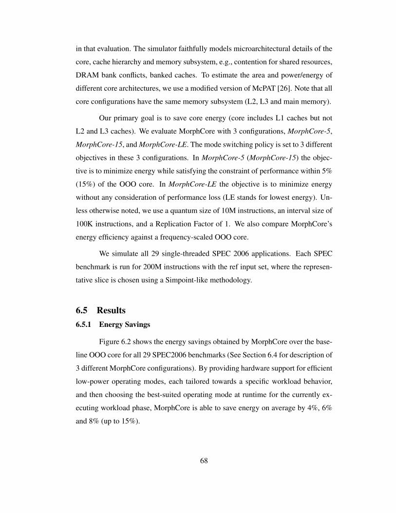
in that evaluation. The simulator faithfully models microarchitectural details of the
core, cache hierarchy and memory subsystem, e.g., contention for shared resources,
DRAM bank conflicts, banked caches. To estimate the area and power/energy of
different core architectures, we use a modified version of McPAT [26]. Note that all
core configurations have the same memory subsystem (L2, L3 and main memory).
Our primary goal is to save core energy (core includes L1 caches but not
L2 and L3 caches). We evaluate MorphCore with 3 configurations, MorphCore-5,
MorphCore-15, andMorphCore-LE. The mode switching policy is set to 3 different
objectives in these 3 configurations. In MorphCore-5 (MorphCore-15) the objec-
tive is to minimize energy while satisfying the constraint of performance within 5%
(15%) of the OOO core. In MorphCore-LE the objective is to minimize energy
without any consideration of performance loss (LE stands for lowest energy). Un-
less otherwise noted, we use a quantum size of 10M instructions, an interval size of
100K instructions, and a Replication Factor of 1. We also compare MorphCore’s
energy efficiency against a frequency-scaled OOO core.
We simulate all 29 single-threaded SPEC 2006 applications. Each SPEC
benchmark is run for 200M instructions with the ref input set, where the represen-
tative slice is chosen using a Simpoint-like methodology.
6.5 Results
6.5.1 Energy Savings
Figure 6.2 shows the energy savings obtained by MorphCore over the base-
line OOO core for all 29 SPEC2006 benchmarks (See Section 6.4 for description of
3 different MorphCore configurations). By providing hardware support for efficient
low-power operating modes, each tailored towards a specific workload behavior,
and then choosing the best-suited operating mode at runtime for the currently ex-
ecuting workload phase, MorphCore is able to save energy on average by 4%, 6%
and 8% (up to 15%).
68
-2 0 2 4 6 8
10 12 14 16
per
l
bzi
p2
gcc
mcf
go
bm
k
hm
mer
sjen
g
lib
qu
an
h2
64
om
net
pp
asta
r
xal
anc
bw
aves
gam
ess
mil
c
zeu
smp
gro
mac
s
cact
us
lesl
ie
nam
d
dea
lII
sop
lex
po
vra
y
calc
uli
x
Gem
s
ton
to
lbm
wrf
sph
inx
gm
eanE
ner
gy
Sav
ing
s o
ver
OO
O (
%)
MorphCore-5% perf lossMorphCore-15% perf loss
MorphCore-LE (Least Energy)
Figure 6.2: Energy-efficiency of MorphCore over OOO core.
6.5.2 Analysis
We explain the energy savings obtained by MorphCore by analyzing sev-
eral benchmarks and by showing the coverage (fraction of instructions executed)
in each of the modes in Figure 6.3 and the performance-energy trade-off of the 3
MorphCore configurations in Figure 6.4.
The benchmark lbm benefits significantly (14% energy savings) in all 3
configurations. Figure 6.3 shows that almost all of the instructions are executed
in 2-wide 192-entry mode (it is a memory-bound benchmark with mostly stable
phase behavior), and Figure 6.4 shows that reducing pipeline width does not hurt
performance significantly (less than 3%). Because of these two factors, lbm is able
to significantly improve energy efficiency with the MorphCore architecture.
Gems is another benchmark that benefits significantly (15% in MorphCore-
LE) by executing most of instructions in 2-wide 48-entry mode, and not hurting
performance significantly. perl, bzip2, h264, and astar are examples of
benchmarks that execute more instructions in low-power modes with MorphCore-
LE as compared to MorphCore-5 or MorphCore-15, and provide more energy sav-
ings. However, the amount of energy savings depends on the performance loss that
they encounter. For example, h264 executes a lot more instructions in low-power
modes as compared to astar (see Figure 6.3), however h264’s increase in en-
69
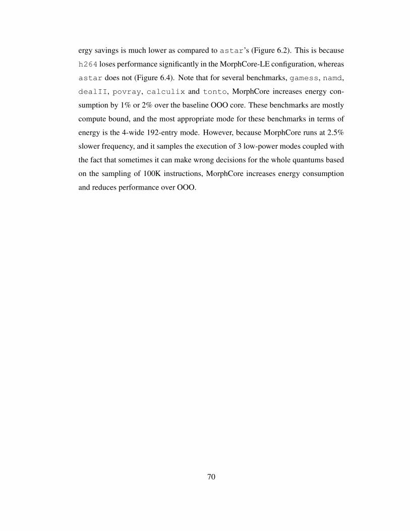
ergy savings is much lower as compared to astar’s (Figure 6.2). This is because
h264 loses performance significantly in the MorphCore-LE configuration, whereas
astar does not (Figure 6.4). Note that for several benchmarks, gamess, namd,
dealII, povray, calculix and tonto, MorphCore increases energy con-
sumption by 1% or 2% over the baseline OOO core. These benchmarks are mostly
compute bound, and the most appropriate mode for these benchmarks in terms of
energy is the 4-wide 192-entry mode. However, because MorphCore runs at 2.5%
slower frequency, and it samples the execution of 3 low-power modes coupled with
the fact that sometimes it can make wrong decisions for the whole quantums based
on the sampling of 100K instructions, MorphCore increases energy consumption
and reduces performance over OOO.
70
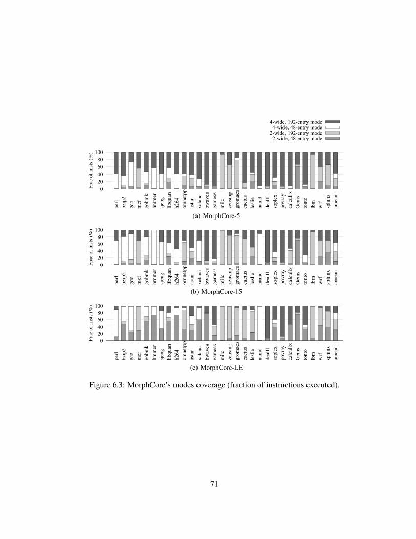
0
20
40
60
80
100
per
l
bzi
p2
gcc
mcf
go
bm
k
hm
mer
sjen
g
lib
qu
an
h2
64
om
net
pp
asta
r
xal
anc
bw
aves
gam
ess
mil
c
zeu
smp
gro
mac
s
cact
us
lesl
ie
nam
d
dea
lII
sop
lex
po
vra
y
calc
uli
x
Gem
s
ton
to
lbm
wrf
sph
inx
amea
n
Fra
c o
f in
sts
(%)
2-wide, 48-entry mode2-wide, 192-entry mode4-wide, 48-entry mode
4-wide, 192-entry mode
(a) MorphCore-5
0
20
40
60
80
100
per
l
bzi
p2
gcc
mcf
go
bm
k
hm
mer
sjen
g
lib
qu
an
h2
64
om
net
pp
asta
r
xal
anc
bw
aves
gam
ess
mil
c
zeu
smp
gro
mac
s
cact
us
lesl
ie
nam
d
dea
lII
sop
lex
po
vra
y
calc
uli
x
Gem
s
ton
to
lbm
wrf
sph
inx
amea
n
Fra
c o
f in
sts
(%)
(b) MorphCore-15
0
20
40
60
80
100
per
l
bzi
p2
gcc
mcf
go
bm
k
hm
mer
sjen
g
lib
qu
an
h2
64
om
net
pp
asta
r
xal
anc
bw
aves
gam
ess
mil
c
zeu
smp
gro
mac
s
cact
us
lesl
ie
nam
d
dea
lII
sop
lex
po
vra
y
calc
uli
x
Gem
s
ton
to
lbm
wrf
sph
inx
amea
n
Fra
c o
f in
sts
(%)
(c) MorphCore-LE
Figure 6.3: MorphCore’s modes coverage (fraction of instructions executed).
71
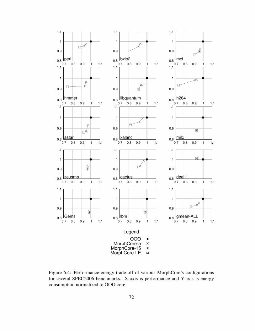
0.8
0.9
1
1.1
0.7 0.8 0.9 1 1.1
perl 0.8
0.9
1
1.1
0.7 0.8 0.9 1 1.1
bzip2 0.8
0.9
1
1.1
0.7 0.8 0.9 1 1.1
mcf
0.8
0.9
1
1.1
0.7 0.8 0.9 1 1.1
hmmer 0.8
0.9
1
1.1
0.7 0.8 0.9 1 1.1
libquantum 0.8
0.9
1
1.1
0.7 0.8 0.9 1 1.1
h264
0.8
0.9
1
1.1
0.7 0.8 0.9 1 1.1
astar 0.8
0.9
1
1.1
0.7 0.8 0.9 1 1.1
xalanc 0.8
0.9
1
1.1
0.7 0.8 0.9 1 1.1
milc
0.8
0.9
1
1.1
0.7 0.8 0.9 1 1.1
zeusmp 0.8
0.9
1
1.1
0.7 0.8 0.9 1 1.1
cactus 0.8
0.9
1
1.1
0.7 0.8 0.9 1 1.1
dealII
0.8
0.9
1
1.1
0.7 0.8 0.9 1 1.1
Gems 0.8
0.9
1
1.1
0.7 0.8 0.9 1 1.1
lbm 0.8
0.9
1
1.1
0.7 0.8 0.9 1 1.1
gmean-ALL
Legend:
OOOMorphCore-5
MorphCore-15MorphCore-LE
Figure 6.4: Performance-energy trade-off of various MorphCore’s configurations
for several SPEC2006 benchmarks. X-axis is performance and Y-axis is energy
consumption normalized to OOO core.
72

6.5.3 Oracle Switching Policy
In order to find out how much of the “potential” energy savings MorphCore
is able to achieve, we compare our low-overhead sampling-based mode switching
policy to an oracle switching policy. The oracle switching policy decides the op-
erating mode at 100K instruction intervals. Note that the mode switching interval
of 100K instructions for the oracle policy is very fine-grained as compared to our
policy in which a mode is chosen for the whole quantum where a quantum size is
10M instructions. The oracle policy chooses the mode as follows: at the start of
every 100K interval, the policy has the “oracle” knowledge of the performance and
energy consumption of the four out-of-order operating modes for the interval, and
thus the policy can make the optimal decision about which mode to run at the start
of the interval.
Figure 6.5 shows performance-energy trade-off of the 3 MorphCore config-
urations and the 3 corresponding oracle configurations. In Oracle-5 (-15), the oracle
policy chooses the lowest energy mode that satisfies the constraint of performance
within 5% (15%) of 4-wide 192-entry OOO mode. In oracle-LE, it chooses the
mode that minimizes the energy consumption during the interval.
We note that our low-overhead sampling-based policy provides operating
points on the performance-energy trade-off space that are close to the oracle for
many workloads. This means that our policy provides most of the benefit (performance-
efficiency, i.e., performance at given energy consumption, or energy-efficiency, i.e.,
energy consumption at given performance) of the oracle switching policy. However,
workloads like bzip2, libquantum, and xalanc show relatively big difference
between our policy and oracle. These workloads have fine-grained phase behaviors,
and our “sample once and use it for the whole (big) quantum” approach does not
work as well as the oracle policy that chooses the optimal mode for every interval.
73
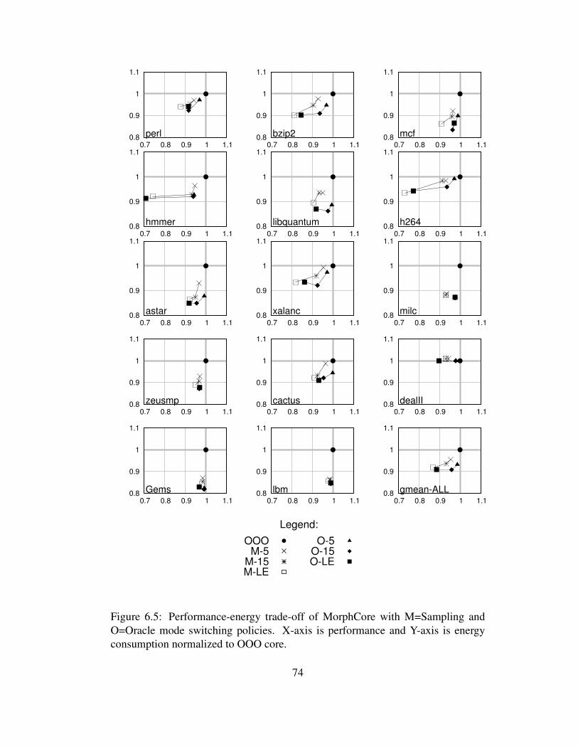
0.8
0.9
1
1.1
0.7 0.8 0.9 1 1.1
perl 0.8
0.9
1
1.1
0.7 0.8 0.9 1 1.1
bzip2 0.8
0.9
1
1.1
0.7 0.8 0.9 1 1.1
mcf
0.8
0.9
1
1.1
0.7 0.8 0.9 1 1.1
hmmer 0.8
0.9
1
1.1
0.7 0.8 0.9 1 1.1
libquantum 0.8
0.9
1
1.1
0.7 0.8 0.9 1 1.1
h264
0.8
0.9
1
1.1
0.7 0.8 0.9 1 1.1
astar 0.8
0.9
1
1.1
0.7 0.8 0.9 1 1.1
xalanc 0.8
0.9
1
1.1
0.7 0.8 0.9 1 1.1
milc
0.8
0.9
1
1.1
0.7 0.8 0.9 1 1.1
zeusmp 0.8
0.9
1
1.1
0.7 0.8 0.9 1 1.1
cactus 0.8
0.9
1
1.1
0.7 0.8 0.9 1 1.1
dealII
0.8
0.9
1
1.1
0.7 0.8 0.9 1 1.1
Gems 0.8
0.9
1
1.1
0.7 0.8 0.9 1 1.1
lbm 0.8
0.9
1
1.1
0.7 0.8 0.9 1 1.1
gmean-ALL
Legend:
OOOM-5
M-15M-LE
O-5O-15O-LE
Figure 6.5: Performance-energy trade-off of MorphCore with M=Sampling and
O=Oracle mode switching policies. X-axis is performance and Y-axis is energy
consumption normalized to OOO core.
74

6.5.4 Dynamic Voltage and Frequency Scaling
Energy consumption of the core changes with the operating voltage Vcc.
The dynamic energy is a quadratic function of Vcc, whereas leakage is an expo-
nential function of Vcc [45]. Thus, reducing Vcc significantly reduces energy con-
sumption. However, the minimum voltage at which the core’s structures operate
reliably limits the down-scaling of voltage. This minimum voltage is often referred
to as Vccmin. Commercial processors are designed with a fixed Vccmin beyond
which the voltage cannot be reduced further. Since we are concerned with energy-
efficiency, we assume that our baseline OOO and MorphCore cores are already
operating at Vccmin. That is why we are interested in mechanisms that can save
energy further without the help of voltage scaling.
Traditionally, the operating frequency of the core is reduced to reduce power
consumption. The effect of reducing frequency on total energy consumption is
shown in Figure 6.6 for 3 MorphCore operating points and 3 slowed-down OOO
core’s points. Slowing down a core by only reducing the frequency of the core can
both increase or decrease its energy consumption. Typically, when the frequency is
reduced, the execution time increases, which increases the leakage energy. On the
other hand, the clock’s dynamic energy may decrease with a slower clock. This may
happen for programs that spend significant time stalled waiting on memory. During
that stalled time period, which typically does not change with core’s frequency (it is
the time memory takes to return the data), a slow clock spends less dynamic energy
since it toggles less as compared to a fast clock.
Figure 6.6 shows that for most of the benchmarks, energy increases with the
slowing down of the core (e.g. compute-bound benchmarks like perl, bzip2,
h264 etc.). However, some memory-intensive programs like mcf, astar, and
lbm decreases energy consumption when the core is slowed down. On average,
slowing down a core only reduces the performance and does not improve energy-
efficiency. On the other hand, MorphCore is able to provide significant energy
savings with similar performance loss.
75
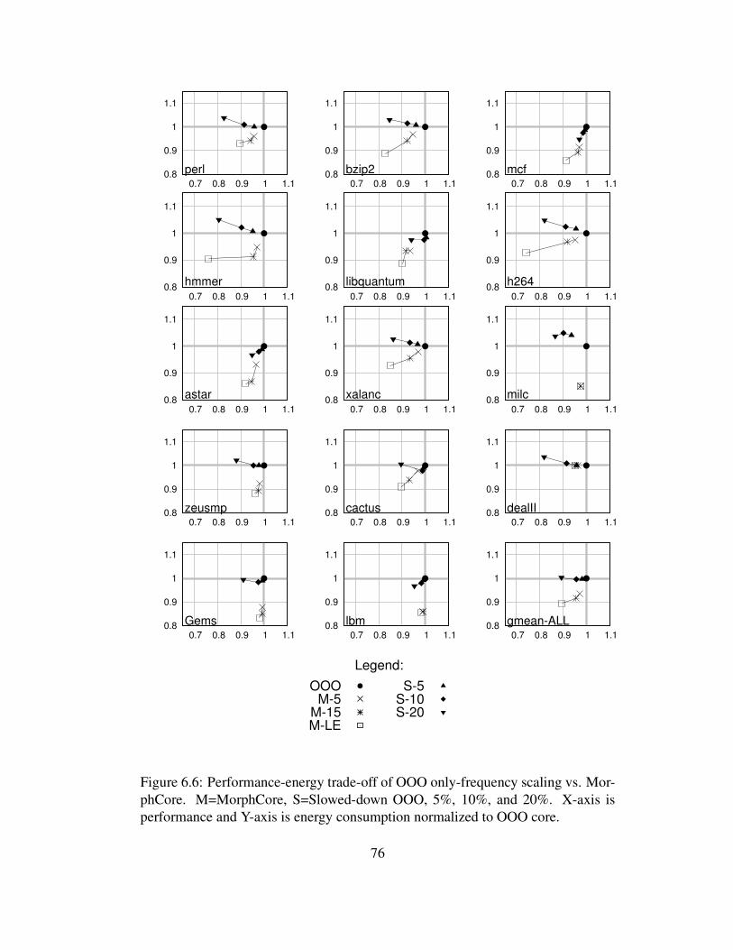
0.8
0.9
1
1.1
0.7 0.8 0.9 1 1.1
perl 0.8
0.9
1
1.1
0.7 0.8 0.9 1 1.1
bzip2 0.8
0.9
1
1.1
0.7 0.8 0.9 1 1.1
mcf
0.8
0.9
1
1.1
0.7 0.8 0.9 1 1.1
hmmer 0.8
0.9
1
1.1
0.7 0.8 0.9 1 1.1
libquantum 0.8
0.9
1
1.1
0.7 0.8 0.9 1 1.1
h264
0.8
0.9
1
1.1
0.7 0.8 0.9 1 1.1
astar 0.8
0.9
1
1.1
0.7 0.8 0.9 1 1.1
xalanc 0.8
0.9
1
1.1
0.7 0.8 0.9 1 1.1
milc
0.8
0.9
1
1.1
0.7 0.8 0.9 1 1.1
zeusmp 0.8
0.9
1
1.1
0.7 0.8 0.9 1 1.1
cactus 0.8
0.9
1
1.1
0.7 0.8 0.9 1 1.1
dealII
0.8
0.9
1
1.1
0.7 0.8 0.9 1 1.1
Gems 0.8
0.9
1
1.1
0.7 0.8 0.9 1 1.1
lbm 0.8
0.9
1
1.1
0.7 0.8 0.9 1 1.1
gmean-ALL
Legend:
OOOM-5
M-15M-LE
S-5S-10S-20
Figure 6.6: Performance-energy trade-off of OOO only-frequency scaling vs. Mor-
phCore. M=MorphCore, S=Slowed-down OOO, 5%, 10%, and 20%. X-axis is
performance and Y-axis is energy consumption normalized to OOO core.
76
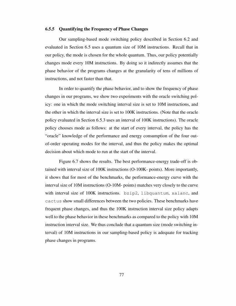
6.5.5 Quantifying the Frequency of Phase Changes
Our sampling-based mode switching policy described in Section 6.2 and
evaluated in Section 6.5 uses a quantum size of 10M instructions. Recall that in
our policy, the mode is chosen for the whole quantum. Thus, our policy potentially
changes mode every 10M instructions. By doing so it indirectly assumes that the
phase behavior of the programs changes at the granularity of tens of millions of
instructions, and not faster than that.
In order to quantify the phase behavior, and to show the frequency of phase
changes in our programs, we show two experiments with the oracle switching pol-
icy: one in which the mode switching interval size is set to 10M instructions, and
the other in which the interval size is set to 100K instructions. (Note that the oracle
policy evaluated in Section 6.5.3 uses an interval of 100K instructions). The oracle
policy chooses mode as follows: at the start of every interval, the policy has the
“oracle” knowledge of the performance and energy consumption of the four out-
of-order operating modes for the interval, and thus the policy makes the optimal
decision about which mode to run at the start of the interval.
Figure 6.7 shows the results. The best performance-energy trade-off is ob-
tained with interval size of 100K instructions (O-100K- points). More importantly,
it shows that for most of the benchmarks, the performance-energy curve with the
interval size of 10M instructions (O-10M- points) matches very closely to the curve
with interval size of 100K instructions. bzip2, libquantum, xalanc, and
cactus show small differences between the two policies. These benchmarks have
frequent phase changes, and thus the 100K instruction interval size policy adapts
well to the phase behavior in these benchmarks as compared to the policy with 10M
instruction interval size. We thus conclude that a quantum size (mode switching in-
terval) of 10M instructions in our sampling-based policy is adequate for tracking
phase changes in programs.
77
0.8
0.9
1
1.1
0.7 0.8 0.9 1 1.1
perl 0.8
0.9
1
1.1
0.7 0.8 0.9 1 1.1
bzip2 0.8
0.9
1
1.1
0.7 0.8 0.9 1 1.1
mcf
0.8
0.9
1
1.1
0.7 0.8 0.9 1 1.1
hmmer 0.8
0.9
1
1.1
0.7 0.8 0.9 1 1.1
libquantum 0.8
0.9
1
1.1
0.7 0.8 0.9 1 1.1
h264
0.8
0.9
1
1.1
0.7 0.8 0.9 1 1.1
astar 0.8
0.9
1
1.1
0.7 0.8 0.9 1 1.1
xalanc 0.8
0.9
1
1.1
0.7 0.8 0.9 1 1.1
milc
0.8
0.9
1
1.1
0.7 0.8 0.9 1 1.1
zeusmp 0.8
0.9
1
1.1
0.7 0.8 0.9 1 1.1
cactus 0.8
0.9
1
1.1
0.7 0.8 0.9 1 1.1
dealII
0.8
0.9
1
1.1
0.7 0.8 0.9 1 1.1
Gems 0.8
0.9
1
1.1
0.7 0.8 0.9 1 1.1
lbm 0.8
0.9
1
1.1
0.7 0.8 0.9 1 1.1
gmean-ALL
Legend:
OOOO-100K-5
O-100K-15O-100K-LE
O-10M-5O-10M-15O-10M-LE
Figure 6.7: Performance-energy trade-off of Oracle policies with different interval
sizes. X-axis is performance and Y-axis is energy consumption normalized to OOO.
78
6.5.6 Comparison to Static Configurations
We also compare MorphCore’s adaptive mode switching policy to static
configurations of MorphCore where the core is operated in one of the three low-
power out-of-order modes during the whole execution. This experiment is done to
find out if switching mode at runtime according to the phase behavior of the pro-
gram provides benefit over fixing the mode for the whole execution. Figure 6.8
shows the results (a representative subset of the benchmarks is shown, average is
over all SPEC2006 benchmarks). On average, it shows that switching mode at
runtime provides the optimal performance and energy as compared to static config-
urations. For a benchmark like mcf the optimal point is the 2-wide 192-entry OOO
static configuration, which provides the best performance and energy consumption
as compared to MorphCore’s adaptive mode switching policy and as compared to
other static configurations. This is because the sampling-based mode switching pol-
icy sometimes ends up making a wrong decision for the whole quantum because of
the interval at which the sampling is done.
79
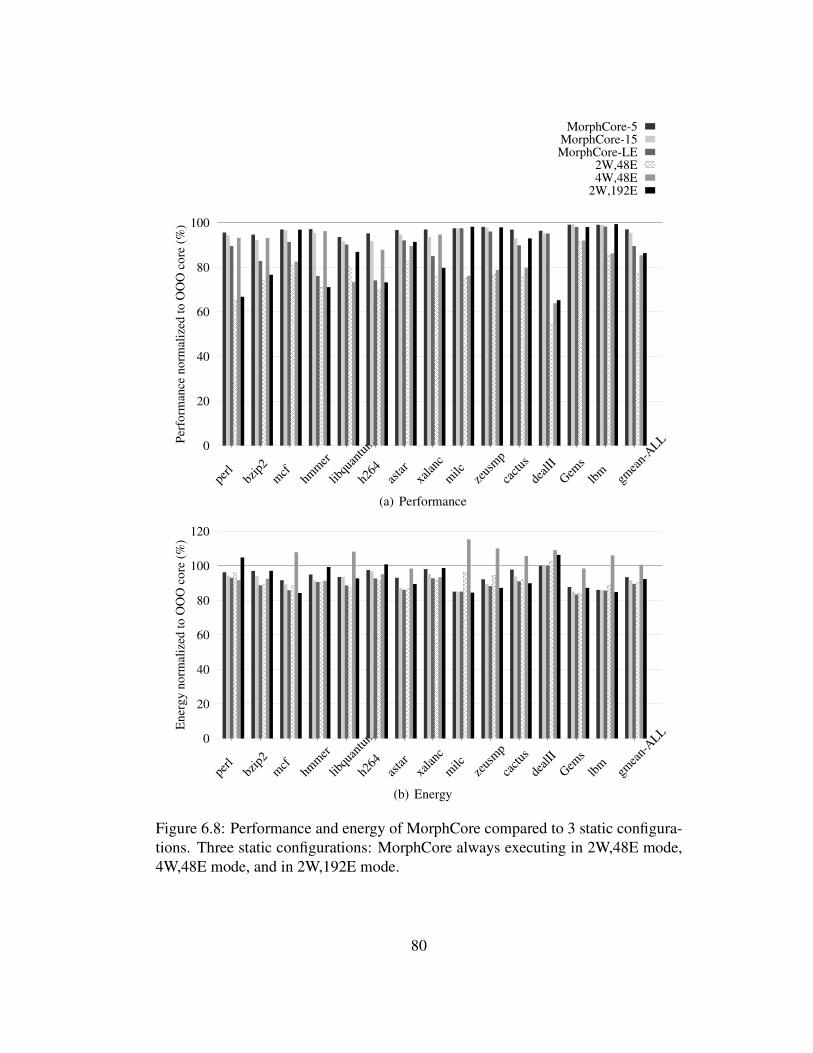
0
20
40
60
80
100
perl
bzip
2
mcf
hmm
er
libqu
antu
m
h264
asta
rxa
lanc
milc
zeus
mp
cact
us
deal
II
Gem
s
lbm
gmea
n-A
LLPer
form
ance
norm
aliz
ed t
o O
OO
core
(%
)
MorphCore-5MorphCore-15MorphCore-LE
2W,48E4W,48E
2W,192E
(a) Performance
0
20
40
60
80
100
120
perl
bzip
2
mcf
hmm
er
libqu
antu
m
h264
asta
rxa
lanc
milc
zeus
mp
cact
us
deal
II
Gem
s
lbm
gmea
n-A
LL
Ener
gy n
orm
aliz
ed t
o O
OO
core
(%
)
(b) Energy
Figure 6.8: Performance and energy of MorphCore compared to 3 static configura-
tions. Three static configurations: MorphCore always executing in 2W,48E mode,
4W,48E mode, and in 2W,192E mode.
80
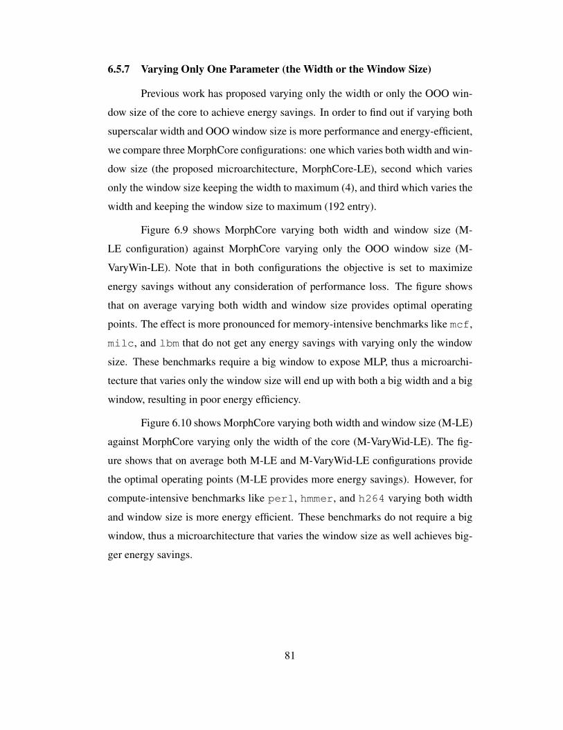
6.5.7 Varying Only One Parameter (the Width or the Window Size)
Previous work has proposed varying only the width or only the OOO win-
dow size of the core to achieve energy savings. In order to find out if varying both
superscalar width and OOO window size is more performance and energy-efficient,
we compare three MorphCore configurations: one which varies both width and win-
dow size (the proposed microarchitecture, MorphCore-LE), second which varies
only the window size keeping the width to maximum (4), and third which varies the
width and keeping the window size to maximum (192 entry).
Figure 6.9 shows MorphCore varying both width and window size (M-
LE configuration) against MorphCore varying only the OOO window size (M-
VaryWin-LE). Note that in both configurations the objective is set to maximize
energy savings without any consideration of performance loss. The figure shows
that on average varying both width and window size provides optimal operating
points. The effect is more pronounced for memory-intensive benchmarks like mcf,
milc, and lbm that do not get any energy savings with varying only the window
size. These benchmarks require a big window to expose MLP, thus a microarchi-
tecture that varies only the window size will end up with both a big width and a big
window, resulting in poor energy efficiency.
Figure 6.10 shows MorphCore varying both width and window size (M-LE)
against MorphCore varying only the width of the core (M-VaryWid-LE). The fig-
ure shows that on average both M-LE and M-VaryWid-LE configurations provide
the optimal operating points (M-LE provides more energy savings). However, for
compute-intensive benchmarks like perl, hmmer, and h264 varying both width
and window size is more energy efficient. These benchmarks do not require a big
window, thus a microarchitecture that varies the window size as well achieves big-
ger energy savings.
81
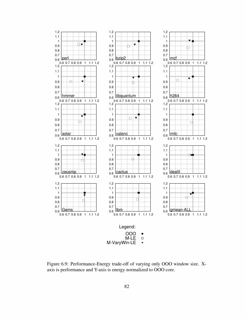
0.6
0.7
0.8
0.9
1
1.1
1.2
0.6 0.7 0.8 0.9 1 1.1 1.2
perl 0.6
0.7
0.8
0.9
1
1.1
1.2
0.6 0.7 0.8 0.9 1 1.1 1.2
bzip2 0.6
0.7
0.8
0.9
1
1.1
1.2
0.6 0.7 0.8 0.9 1 1.1 1.2
mcf
0.6
0.7
0.8
0.9
1
1.1
1.2
0.6 0.7 0.8 0.9 1 1.1 1.2
hmmer 0.6
0.7
0.8
0.9
1
1.1
1.2
0.6 0.7 0.8 0.9 1 1.1 1.2
libquantum 0.6
0.7
0.8
0.9
1
1.1
1.2
0.6 0.7 0.8 0.9 1 1.1 1.2
h264
0.6
0.7
0.8
0.9
1
1.1
1.2
0.6 0.7 0.8 0.9 1 1.1 1.2
astar 0.6
0.7
0.8
0.9
1
1.1
1.2
0.6 0.7 0.8 0.9 1 1.1 1.2
xalanc 0.6
0.7
0.8
0.9
1
1.1
1.2
0.6 0.7 0.8 0.9 1 1.1 1.2
milc
0.6
0.7
0.8
0.9
1
1.1
1.2
0.6 0.7 0.8 0.9 1 1.1 1.2
zeusmp 0.6
0.7
0.8
0.9
1
1.1
1.2
0.6 0.7 0.8 0.9 1 1.1 1.2
cactus 0.6
0.7
0.8
0.9
1
1.1
1.2
0.6 0.7 0.8 0.9 1 1.1 1.2
dealII
0.6
0.7
0.8
0.9
1
1.1
1.2
0.6 0.7 0.8 0.9 1 1.1 1.2
Gems 0.6
0.7
0.8
0.9
1
1.1
1.2
0.6 0.7 0.8 0.9 1 1.1 1.2
lbm 0.6
0.7
0.8
0.9
1
1.1
1.2
0.6 0.7 0.8 0.9 1 1.1 1.2
gmean-ALL
Legend:
OOOM-LE
M-VaryWin-LE
Figure 6.9: Performance-Energy trade-off of varying only OOO window size. X-
axis is performance and Y-axis is energy normalized to OOO core.
82

0.6
0.7
0.8
0.9
1
1.1
1.2
0.6 0.7 0.8 0.9 1 1.1 1.2
perl 0.6
0.7
0.8
0.9
1
1.1
1.2
0.6 0.7 0.8 0.9 1 1.1 1.2
bzip2 0.6
0.7
0.8
0.9
1
1.1
1.2
0.6 0.7 0.8 0.9 1 1.1 1.2
mcf
0.6
0.7
0.8
0.9
1
1.1
1.2
0.6 0.7 0.8 0.9 1 1.1 1.2
hmmer 0.6
0.7
0.8
0.9
1
1.1
1.2
0.6 0.7 0.8 0.9 1 1.1 1.2
libquantum 0.6
0.7
0.8
0.9
1
1.1
1.2
0.6 0.7 0.8 0.9 1 1.1 1.2
h264
0.6
0.7
0.8
0.9
1
1.1
1.2
0.6 0.7 0.8 0.9 1 1.1 1.2
astar 0.6
0.7
0.8
0.9
1
1.1
1.2
0.6 0.7 0.8 0.9 1 1.1 1.2
xalanc 0.6
0.7
0.8
0.9
1
1.1
1.2
0.6 0.7 0.8 0.9 1 1.1 1.2
milc
0.6
0.7
0.8
0.9
1
1.1
1.2
0.6 0.7 0.8 0.9 1 1.1 1.2
zeusmp 0.6
0.7
0.8
0.9
1
1.1
1.2
0.6 0.7 0.8 0.9 1 1.1 1.2
cactus 0.6
0.7
0.8
0.9
1
1.1
1.2
0.6 0.7 0.8 0.9 1 1.1 1.2
dealII
0.6
0.7
0.8
0.9
1
1.1
1.2
0.6 0.7 0.8 0.9 1 1.1 1.2
Gems 0.6
0.7
0.8
0.9
1
1.1
1.2
0.6 0.7 0.8 0.9 1 1.1 1.2
lbm 0.6
0.7
0.8
0.9
1
1.1
1.2
0.6 0.7 0.8 0.9 1 1.1 1.2
gmean-ALL
Legend:
OOOM-LE
M-VaryWid-LE
Figure 6.10: Performance-Energy trade-off of varying only superscalar width. X-
axis is performance and Y-axis is energy normalized to OOO core.
83
6.5.8 Comparison with the Cores Optimized for Low-Power
MorphCore provides energy savings over a traditional OOO core for single-
thread programs by providing the hardware support for three low-power out-of-
order operating modes and switching between them at runtime. We would like to
find out how MorphCore’s energy efficiency compares to the cores that are specif-
ically designed for low-power (and for low-energy) operation. Two such cores de-
scribed in the Methodology section (Section 6.4) are MED and SMALL. MED is a
2-wide medium OOO window (48-entry) core. SMALL is a 2-wide in-order core.
Figure 6.11 shows the average performance and energy of four cores: a
traditional OOO core, MorphCore, MED, and SMALL. We note that MorphCore
point is MorphCore-LE (the configuration with least energy consumption). The
figure shows that SMALL is not energy-efficient because it is an in-order core and
loses performance significantly. This increases leakage energy significantly which
outweighs any energy benefit because of its lean microarchitecture. MED is very
energy-efficient, and saves 38% energy. Although the data shows that MorphCore
does not achieve energy savings close to MED, it shows that MorphCore brings
energy efficiency of a big core more towards the low-power optimized cores.
0.4
0.5
0.6
0.7
0.8
0.9
1
1.1
1.2
0.3 0.4 0.5 0.6 0.7 0.8 0.9 1 1.1 1.2
gmean-ALL
Legend:
OOOM-LEMED
SMALL
Figure 6.11: Performance-Energy trade-off of MorphCore-LE vs. cores that are
optimized for low-power. X-axis is performance and Y-axis is energy normalized
to OOO.
84
Chapter 7
Related Work
7.1 Reconfigurable Cores
Most closely related to our work are the numerous proposals that use recon-
figurable cores to handle both latency and throughput sensitive workloads [19, 3,
21, 34, 33, 44, 10, 11]. All these proposals share the same fundamental idea: build
a chip with “simpler cores” and “combine” them using additional logic at runtime
to form a high performance out-of-order core when high single thread performance
is required. The cores operate independently in throughput mode.
Core Fusion [19], Federation Cores [3], Widget [44], and Forwardflow [10]
provide scalability without any compiler/ISA support, similar to MorphCore, so
we first discuss them. Core Fusion [19] is an architecture where four medium-
sized OOO cores (2-wide, 48 entry OOO window) “fuse” to form a large (poten-
tially 8-wide) out-of-order core when TLP is low. Federation Cores combines 2
in-order cores to form a lightweight OOO core. Widget and Forwardflow are sea-
of-resources designs that dynamically allocate simple and distributed resources to
achieve OOO-like performance.
There are several shortcomings with the approach of combining simpler
cores to form a large OOO core. First, the performance benefit of fusing the cores
is limited because the constituent small cores operate in lock-step. Furthermore,
fusing adds latencies between the pipeline stages of the fused core, and requires
inter-core communication if dependent operations are steered to different cores.
This approach of obtaining high performance is exactly opposite of the “low-latency
instruction execution” design approach of traditional large cores (the IPC drops sig-
nificantly if latency between the pipeline stages/blocks is increased in a large core),
85
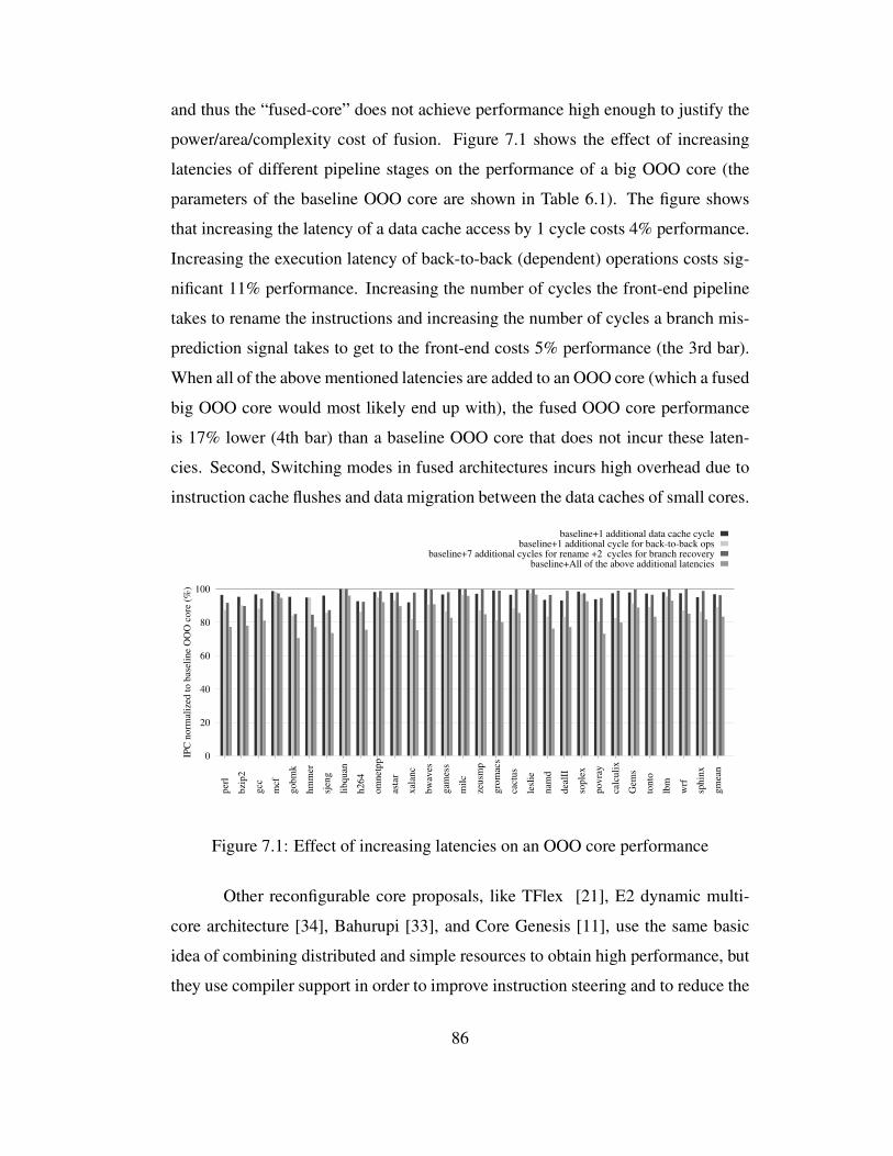
and thus the “fused-core” does not achieve performance high enough to justify the
power/area/complexity cost of fusion. Figure 7.1 shows the effect of increasing
latencies of different pipeline stages on the performance of a big OOO core (the
parameters of the baseline OOO core are shown in Table 6.1). The figure shows
that increasing the latency of a data cache access by 1 cycle costs 4% performance.
Increasing the execution latency of back-to-back (dependent) operations costs sig-
nificant 11% performance. Increasing the number of cycles the front-end pipeline
takes to rename the instructions and increasing the number of cycles a branch mis-
prediction signal takes to get to the front-end costs 5% performance (the 3rd bar).
When all of the above mentioned latencies are added to an OOO core (which a fused
big OOO core would most likely end up with), the fused OOO core performance
is 17% lower (4th bar) than a baseline OOO core that does not incur these laten-
cies. Second, Switching modes in fused architectures incurs high overhead due to
instruction cache flushes and data migration between the data caches of small cores.
0
20
40
60
80
100
per
l
bzi
p2
gcc
mcf
gobm
k
hm
mer
sjen
g
libquan
h264
om
net
pp
asta
r
xal
anc
bw
aves
gam
ess
mil
c
zeusm
p
gro
mac
s
cact
us
lesl
ie
nam
d
dea
lII
sople
x
povra
y
calc
uli
x
Gem
s
tonto
lbm
wrf
sphin
x
gm
ean
IPC
norm
aliz
ed t
o b
asel
ine
OO
O c
ore
(%
)
baseline+1 additional data cache cyclebaseline+1 additional cycle for back-to-back ops
baseline+7 additional cycles for rename +2 cycles for branch recoverybaseline+All of the above additional latencies
Figure 7.1: Effect of increasing latencies on an OOO core performance
Other reconfigurable core proposals, like TFlex [21], E2 dynamic multi-
core architecture [34], Bahurupi [33], and Core Genesis [11], use the same basic
idea of combining distributed and simple resources to obtain high performance, but
they use compiler support in order to improve instruction steering and to reduce the
86
number of accesses that need to be done to centralized structures, and thus improve
upon the initial Core Fusion idea. However they require complicated compiler anal-
ysis and instruction scheduling in order to map instruction blocks to distributed
hardware. MorphCore does not require compiler/ISA support, and therefore can
run legacy binaries without modification.
7.2 Heterogeneous Chip-Multiprocessors
Heterogeneous (or Asymmetric) Chip Multiprocessors (ACMPs) [24, 25,
12, 29, 38] have been proposed to handle workloads with serial and parallel phases.
These proposals augment one or a few large out-of-order cores with many in-order
and small out-of-order cores. The large core is used to run program phases with
low TLP while the small cores run phases with high TLP. The ACMP has two
limitations: (1) the ACMP’s configuration, the number of large and small cores,
is fixed at design time. This limits the ACMP’s ability to adapt to varied amount
of TLP found in applications. (2) the ACMP may incur a high cost when a thread
is migrated between a small and a large core: it incurs the cost of turning ON and
migrating the thread state/data to the “accelerator” core(s) (Data Marshaling [39]
has been proposed to alleviate this problem, however DM requires complicated
compiler support and may not be applicable to all workloads). This limits the ability
of the ACMP to provide acceleration at relatively fine-grained intervals.
7.3 Adapting a Core’s Resources to ILP and MLP
Several studies have proposed adapting an OOO core’s resources to fit the
workload characteristics in order to save energy and power. These proposals fall in
two categories: proposals that vary the size of structures supporting OOO execution,
and proposals that vary pipeline width.
Buyuktosunoglu et al. [5, 6] propose varying the number of Reservation Sta-
tion (RS) entries and describe the circuit implementation for doing so. Ponomarev
et al. [32] propose adapting the size of the RS, load/store queue and ROB.
87
Bahar et al. [2] and Maro et al. [28] propose disabling cluster(s) in a clustered-
architecture (a cluster is made up of execution units, the register file and the RS).
Maro et al. [28] also propose clock-gating the disabled clusters. Hu et al. [16] pro-
pose power-gating the functional units. Flicker [31] proposes varying the pipeline
width across the whole core.
Our contributions over previous work are as follows: First, by varying both
superscalar width and OOO window size, we not only achieve the collective benefit
of previous schemes that vary only one resource at a time, we also get the bene-
fit of reducing both resources simultaneously through the 2-wide 48-entry mode.
Section 6.5 shows that several benchmarks benefit from the 2-wide 48-entry mode.
Gems obtains the largest energy savings of 17% by executing almost all instructions
in this mode. Also, note that the MorphCore-LE configuration which achieves the
largest energy savings across all benchmarks spends most of its time in 2-wide
48-entry mode. Thus, we conclude that varying both superscalar width and OOO
window size results in an adaptive processor that provides a wide operating range
through 4 operating modes and maximum energy savings as well. Second, we pro-
pose a simple yet-effective policy to decide the width and window size combination.
Previous work that varies only one resource at a time does so based on the utiliza-
tion or occupancy of the resource, e.g., when varying the number of functional
units that are ON, one can look at the utilization of ALUs that are currently ON,
and depending on this utilization being above or below a certain threshold, some
ALUs could be turned ON or OFF. When varying multiple resources, the benefit
of the combination of resource sizes needs to be determined. We have proposed a
simple yet effective sampling-based mode switching policy to decide the width and
window size, and we show that it provides benefit close to the oracle. Third, even
though Flicker [31] mentions reducing the pipeline width of the core, it doesn’t de-
scribe the microarchitecture for doing so or the resultant energy savings. To our
knowledge, our proposal is the first to describe in detail a mechanism for turning
off half of the pipeline width and describe the resulting energy savings.
88
7.4 Techniques to Scale a Core’s Performance and Energy
7.4.1 Dynamic Voltage and Frequency Scaling
Dynamic Voltage and Frequency Scaling (DVFS) [15, 4] is a widely-used
technique to scale a core’s performance and energy (e.g., Intel Turbo Boost [18]).
For example, a large OOO core can be run at higher voltage and frequency to in-
crease its performance and to achieve the performance comparable to the small
cores for multi-threaded workloads. However, increasing performance using DVFS
costs a significant increase in energy consumption (energy is a quadratic function of
voltage). Thus, DVFS is not an efficient way of increasing OOO core performance.
In contrast, MorphCore increases the baseline core performance significantly while
reducing energy consumption for multi-threaded workloads. On the other hand,
decreasing energy consumption using DVFS is a very effective technique since en-
ergy reduces quadratically with voltage/frequency whereas performance reduces
only linearly with voltage/frequency. However, the minimum voltage at which the
core’s structures operate reliably limits the down-scaling of voltage. That is why
microarchitectural proposals like MorphCore are very effective in saving energy
further without the help of voltage scaling.
7.4.2 Simultaneous Multi-Threading
Simultaneous Multi-Threading (SMT) [14, 47, 42] was proposed to improve
resource utilization by executing multiple threads on the same core. However, un-
like MorphCore, previously proposed SMT techniques increase the area and com-
plexity of the core (which may increase energy requirements), whereas MorphCore
leverages existing structures and does not increase area and complexity. Hily and
Seznec observed in [13] that out-of-order execution becomes unnecessary when
thread-level parallelism is available. The MorphCore microarchitecture saves en-
ergy and improves performance when executing multi-threaded workloads by build-
ing on their insight.
89
Chapter 8
Conclusion
8.1 Summary
I propose the MorphCore microarchitecture which is designed to improve
the performance and energy-efficiency of both single-threaded and multi-threaded
programs. MorphCore does so by adapting to TLP, ILP, and MLP in programs, and
by operating in one of five modes: (1) as a 4-wide 8-way-threaded in-order SMT
core, (2) as a 4-wide 192-entry OOO core, 3) as a 4-wide 48-entry OOO core, 4) as a
2-wide 192-entry OOO core, and 5) as a 2-wide 48-entry OOO core. My evaluation
with single-threaded benchmarks from SPEC2006 and 14 multi-threaded bench-
marks shows that MorphCore provides high performance and energy efficiency as
needed by adapting to the behavior of the program. When highest performance
is desired for single-thread workloads, MorphCore provides performance similar
to a traditional out-of-order core. When the goal is to save energy for single-
threaded workloads, MorphCore reduces energy by 8%. When highest performance
on multi-threaded workloads is desired, MorphCore provides performance similar
to throughput-optimized cores, significantly higher (21%) than the baseline out-of-
order core.
I therefore suggest that MorphCore is a promising direction for increasing
performance, saving energy, and accommodating workload diversity while requir-
ing small changes to a traditional out-of-order core.
8.2 Limitations and Future Work
The work presented in this thesis can certainly be extended. I envision future
work in six areas:
90
• New modes and mode switching policies: I proposed a simple mode switch-
ing policy based on the number of active threads. Future research can explore
other mode switching policies based on estimating the benefit or loss of In-
Order mode over OutofOrder mode. For example, exploring policies that
take into account: locality and parallelism in DRAM, last-level cache ca-
pacity pressure, and contention for resources in the core (Icache, TLB etc.).
Similarly, future research can explore new execution modes, such as a hybrid
in-order/out-of-order mode for applications with medium parallelism. An-
other area of future research is to enable turning off parts of physical register
file even in InOrder mode when fewer threads are needed to sustain the high
core throughput.
• OS and runtime systems research: MorphCore provides new research op-
portunities for OS and runtime systems to develop hardware/software co-
operative mechanisms to schedule and accelerate threads on MorphCore, e.g.
based on resource constraints, software hints provided by the application, and
runtime measurements from the hardware.
• New uses of many threads on the core: MorphCore provides an area- and
energy-efficient way to support many threads on the core. It opens up new
research opportunities in the area of speculative multi-threading and improv-
ing the single-thread performance using speculative helper threads on a single
core.
• Cache/memory system design: Future research can explore cache/memory
system design (cache replacement, insertion, or partitioning policies, mem-
ory scheduling etc.) for heterogeneous architectures like MorphCore. For
example, how to design a cache and a memory system that sometimes sup-
port 2 fast threads and at other times support 8 slow threads.
• Mechanisms to quickly fill/spill threads: MorphCore provides the capability
to efficiently run many threads in-order on the core. However, the number
91
of threads that can run on MorphCore simultaneously is limited by the space
in the Physical Register File. Future research can explore energy-efficient
extreme multithreading like GPUs on MorphCore by studying methods to
quickly fill/spill thread contexts.
• Implications for Composite Core designs: The work in this thesis shows that
varying both superscalar width and OOO window size provides maximum
energy savings, and a wide operating range in terms of the performance-
energy trade-off. Researchers have recently proposed Composite Core [27]
that has heterogeneity built-in (a core with one front-end and two back-ends,
in-order and out-of-order). Composite Core provides a separate back-end for
in-order execution as opposed to the more performance and energy-efficient
approach taken by MorphCore that provides support for highly-threaded in-
order SMT execution by reusing many structures of the core (including the
Physical Register File and the Reservation Station). Future research can ex-
plore new composite core designs that have dedicated pipelines for different
widths and window sizes.
92
Bibliography
[1] MySQL database engine 5.0.1. http://www.mysql.com.
[2] R. I. Bahar and S. Manne. Power and energy reduction via pipeline balancing.
In Proceedings of the 28th Annual International Symposium on Computer Ar-
chitecture, ISCA ’01, pages 218–229, New York, NY, USA, 2001. ACM.
[3] M. Boyer, D. Tarjan, and K. Skadron. Federation: Boosting per-thread perfor-
mance of throughput-oriented manycore architectures. ACM Trans. Archit.
Code Optim. (TACO), 2010.
[4] T. Burd and R. Brodersen. Energy efficient CMOS microprocessor design. In
Proceedings of the Twenty-Eighth Hawaii International Conference on System
Sciences, 1995.
[5] A. Buyuktosunoglu, D. Albonesi, S. Schuster, D. Brooks, P. Bose, and P. Cook.
A circuit level implementation of an adaptive issue queue for power-aware mi-
croprocessors. In Proceedings of the 11th Great Lakes Symposium on VLSI,
GLSVLSI ’01, pages 73–78, New York, NY, USA, 2001. ACM.
[6] A. Buyuktosunoglu, T. Karkhanis, D. H. Albonesi, and P. Bose. Energy ef-
ficient co-adaptive instruction fetch and issue. In Proceedings of the 30th
Annual International Symposium on Computer Architecture, ISCA ’03, pages
147–156, New York, NY, USA, 2003. ACM.
[7] Z. Chishti and T. N. Vijaykumar. Optimal power/performance pipeline depth
for SMT in scaled technologies. IEEE Trans. on Computers, Jan. 2008.
[8] A. J. Dorta et al. The OpenMP source code repository. In Euromicro, 2005.
93
[9] K. Ghose and M. B. Kamble. Reducing power in superscalar processor caches
using subbanking, multiple line buffers and bit-line segmentation. In Pro-
ceedings of the 1999 International Symposium on Low Power Electronics and
Design, ISLPED ’99, pages 70–75, New York, NY, USA, 1999. ACM.
[10] D. Gibson and D. A. Wood. Forwardflow: a scalable core for power-constrained
CMPs. In ISCA, 2010.
[11] S. Gupta, S. Feng, A. Ansari, and S. Mahlke. Erasing core boundaries for
robust and configurable performance. InMICRO, 2010.
[12] M. D. Hill and M. R. Marty. Amdahl’s law in Multicore Era. Technical
Report CS-TR-2007-1593, Univ. of Wisconsin, 2007.
[13] S. Hily and A. Seznec. Out-of-order execution may not be cost-effective on
processors featuring simultaneous multithreading. In HPCA, 1999.
[14] H. Hirata et al. An elementary processor architecture with simultaneous in-
struction issuing from multiple threads. In ISCA, 1992.
[15] M. Horowitz et al. Low-power digital design. In IEEE Symposium on Low
Power Electronics, 1994.
[16] Z. Hu, A. Buyuktosunoglu, V. Srinivasan, V. Zyuban, H. Jacobson, and P. Bose.
Microarchitectural techniques for power gating of execution units. In Pro-
ceedings of the 2004 International Symposium on Low Power Electronics and
Design, ISLPED ’04, pages 32–37, New York, NY, USA, 2004. ACM.
[17] Intel. Intel 64 and IA-32 Architectures Software Dev. Manual, Vol-1, 2011.
[18] Intel Turbo Boost Technology. Intel Corporation.
[19] E. Ipek et al. Core fusion: accommodating software diversity in chip multi-
processors. In ISCA-34, 2007.
94
[20] H. Jacobson, P. Bose, Z. Hu, A. Buyuktosunoglu, V. Zyuban, R. Eickemeyer,
L. Eisen, J. Griswell, D. Logan, B. Sinharoy, and J. Tendler. Stretching the
limits of clock-gating efficiency in server-class processors. In Proceedings of
the 11th International Symposium on High-Performance Computer Architec-
ture, HPCA ’05, pages 238–242, Washington, DC, USA, 2005. IEEE Com-
puter Society.
[21] C. Kim et al. Composable lightweight processors. In MICRO-40, 2007.
[22] D. Koufaty and D. Marr. Hyperthreading technology in the Netburst microar-
chitecture. IEEE Micro, 2003.
[23] H. Kredel. Source code for traveling salesman problem (tsp). http://krum.rz.uni-
mannheim.de/ba-pp-2007/java/index.html.
[24] R. Kumar et al. Single-isa heterogeneous multi-core architectures: The po-
tential for processor power reduction. In MICRO 36, 2003.
[25] R. Kumar et al. Single-ISA Heterogeneous Multi-Core Architectures for Mul-
tithreaded Workload Performance. In ISCA 31, 2004.
[26] S. Li et al. McPAT: an integrated power, area, and timing modeling frame-
work for multicore and manycore architectures. In MICRO 42, 2009.
[27] A. Lukefahr, S. Padmanabha, R. Das, F. M. Sleiman, R. Dreslinski, T. F.
Wenisch, and S. Mahlke. Composite cores: Pushing heterogeneity into a
core. In Proceedings of the 2012 45th Annual IEEE/ACM International Sym-
posium on Microarchitecture, MICRO-45, pages 317–328, Washington, DC,
USA, 2012. IEEE Computer Society.
[28] R. Maro, Y. Bai, and R. I. Bahar. Dynamically reconfiguring processor re-
sources to reduce power consumption in high-performance processors. In
Proceedings of the First International Workshop on Power-Aware Computer
Systems-Revised Papers, PACS ’00, pages 97–111, London, UK, UK, 2001.
Springer-Verlag.
95
[29] T. Y. Morad et al. Performance, power efficiency and scalability of asymmet-
ric cluster chip multiprocessors. 2006.
[30] NVIDIA Corporation. CUDA SDK code samples, 2009.
[31] P. Petrica, A. M. Izraelevitz, D. H. Albonesi, and C. A. Shoemaker. Flicker:
A dynamically adaptive architecture for power limited multicore systems. In
Proceedings of the 40th Annual International Symposium on Computer Archi-
tecture, ISCA ’13, pages 13–23, New York, NY, USA, 2013. ACM.
[32] D. Ponomarev, G. Kucuk, and K. Ghose. Reducing power requirements of
instruction scheduling through dynamic allocation of multiple datapath re-
sources. In Proceedings of the 34th Annual ACM/IEEE International Sym-
posium on Microarchitecture, MICRO 34, pages 90–101, Washington, DC,
USA, 2001. IEEE Computer Society.
[33] M. Pricopi and T. Mitra. Bahurupi: A polymorphic heterogeneous multi-core
architecture. ACM TACO, January 2012.
[34] A. Putnam et al. Dynamic vectorization in the E2 dynamic multicore archi-
tecture. SIGARCH Comp. Arch. News, 2011.
[35] D. Sager, D. P. Group, and I. Corp. The microarchitecture of the pentium 4
processor. Intel Technology Journal, 1:2001, 2001.
[36] T. Sherwood, S. Sair, and B. Calder. Phase tracking and prediction. SIGARCH
Comput. Archit. News, 31(2):336–349, May 2003.
[37] J. Stark et al. On pipelining dynamic instruction scheduling logic. In
MICRO-33, 2000.
[38] M. A. Suleman et al. Accelerating critical section execution with asymmetric
multi-core architectures. In ASPLOS, 2009.
[39] M. A. Suleman et al. Data marshaling for multi-core architectures. ISCA,
2010.
96
[40] SysBench: a system performance benchmark v0.4.8. http://sysbench.sourceforge.net.
[41] Tornado Web Server. Source code. http://tornado.sourceforge.net/, 2008.
[42] D. M. Tullsen et al. Simultaneous multithreading: Maximizing on-chip par-
allelism. In ISCA-22, 1995.
[43] E. Tune, R. Kumar, D. M. Tullsen, and B. Calder. Balanced multithread-
ing: Increasing throughput via a low cost multithreading hierarchy. In Pro-
ceedings of the 37th Annual IEEE/ACM International Symposium on Microar-
chitecture, MICRO 37, pages 183–194, Washington, DC, USA, 2004. IEEE
Computer Society.
[44] Y. Watanabe et al. Widget: Wisconsin decoupled grid execution tiles. In
ISCA, 2010.
[45] C. Wilkerson, H. Gao, A. Alameldeen, Z. Chishti, M. Khellah, and S.-L. Lu.
Trading off cache capacity for low-voltage operation. Micro, IEEE, 29(1):96–
103, Jan 2009.
[46] S. C. Woo et al. The SPLASH-2 programs: Characterization and method-
ological considerations. In ISCA-22, 1995.
[47] W. Yamamoto et al. Performance estimation of multistreamed, superscalar
processors. In Hawaii Intl. Conf. on System Sciences, 1994.
97


![A Performance Analysis Framework for Optimizing OpenCL ...hebs/pub/main_HPCA16.pdf · energy efficiency, and can deliver superb performance for some applications [8]. Despite the](https://img.dokumen.tips/doc/110x75/601ce4888fdc2d37603f1cbe/a-performance-analysis-framework-for-optimizing-opencl-hebspubmain-energy.jpg)


![Applied Thermal Engineering · 2 trans-critical systems, their energy efficiency performance needs to be investigated. Many researchers ([8–14]) compared the performance of CO](https://img.dokumen.tips/doc/110x75/5fd675b4065e823d79101ff1/applied-thermal-engineering-2-trans-critical-systems-their-energy-eficiency-performance.jpg)