Embed Size (px)
Citation preview
MEE10:60
Performance analysis of MIMO-OFDM
Systems with focus on WiMAX
Muhammad Hassan
Email: [email protected]
Abdul Sattar
Email: [email protected]
This thesis is presented as part of Degree of
Master of Science in Electrical Engineering
Blekinge Institute of Technology, Sweden
2010
________________________________________________________________
Supervisor: Maria Erman
Examiner: Dr. Jorgen Nordberg
Performance analysis of MIMO-OFDM Systems with focus on WiMAX 2010
Blekinge Tekniska Högskola, KarlsKrona Page 2
Abstract:
The demand of different multimedia services and different internet supported
applications on mobile devices requires a high speed data rate and good service of
quality. This can be obtained by implementing multiple Antenna technology on both
stations i.e. User terminal and base station with an appropriate coding technique, and
on the other hand MIMO can fulfill 3G & 4G demand and standard with a
combination of other techniques. The MIMO diversity and MIMO multiplexing are the
key factors to discuss and matter of concern is to achieve and support high speed data
rate. MIMO multiplexing is a way to gain robustness and achievement in speed of data
information.
This thesis work describes a brief overview of WiMAX technology and MIMO-
OFDM system and it also discusses the simplest Space time block code (STBC)
known as Alamouti Space Time Code. The research approach is a literary survey to
have theoretical understanding of the MIMO-OFDM system and WiMAX.
The system‘s error performance is analyzed through simulation which showed the
simulated results of Multi-Rate Resource Control (MRRC) scheme and Alamouti
scheme are identical. And also the Bit Error Rate (BER) were checked for different
MIMO systems, the simulation results shows that the BER improved to agreeable
value also gains maximum diversity when the number of antennas increased on the
receiver side. By improving the BER, we will get the better QoS. Matlab simulation
has been performed, and presented the results, which shows the considerable error free
transmission (FEC) for MIMO systems in WiMAX technology.

Performance analysis of MIMO-OFDM Systems with focus on WiMAX 2010
Blekinge Tekniska Högskola, KarlsKrona Page 3
Acknowledgment:
In the name of greatest All mighty ALLAH who has always bless me with potential knowledge and
success.
We are very thankful to our supervisor Maria Erman for her supervision and Examiner Dr. Jörgen
Nordberg for their support during our thesis.
We are also thankful to our friends who help us during our hard times when we need their assistance
during our thesis report.
We are especially thankful to our parents, brothers and sisters who have always provided us the
courage, strength, best wishes, moral and financial support during our whole career.
We also have best regards for BTH faculty especially Mikael Åsman and Lena Magnusson who had
been helpful throughout our master´s degree.
Performance analysis of MIMO-OFDM Systems with focus on WiMAX 2010
Blekinge Tekniska Högskola, KarlsKrona Page 4
Table of Contents
Abstract: ..................................................................................................................................... 2
Acknowledgment: ...................................................................................................................... 3
Table of Contents ....................................................................................................................... 4
List of Figures ........................................................................................................................ 7
List of Acronyms ................................................................................................................... 8
CHAPTER 1: ............................................................................................................................ 10
1.1 Introduction ................................................................................................................... 10
1.2 Aims and Achievements ................................................................................................ 10
1.3 Thesis Structure: ............................................................................................................ 11
CHAPTER 2: The IEEE (Standards) ....................................................................................... 12
2.1 THE IEEE (Standards-Based Solutions) ....................................................................... 12
2.2 Overview of the IEEE Standards .................................................................................. 12
2.2.1 IEEE 802.11 .............................................................................................................. 12
2.2.2 IEEE 802.16 .............................................................................................................. 13
2.2.3 2-11 GHz & 10-66 GHz ........................................................................................... 14
2.3 How the IEEE 802.16 Works ........................................................................................ 15
2.4 Fading ............................................................................................................................ 16
2.5 The propagation of wireless Channels .......................................................................... 16
2.5.1 The Ground wave propogation ................................................................................. 17
2.5.2 The Sky wave propagation ....................................................................................... 17
2.5.3 The Line of sight propagation .................................................................................. 18
CHAPTER 3: Multi Carrier Modulation .................................................................................. 20
3.1 Multi-Carrier Modulation .............................................................................................. 20
3.1.1 FDM and OFDM ...................................................................................................... 21
3.2 OFDM ........................................................................................................................... 21
3.2.2 Fourier Transform ..................................................................................................... 23
3.2.3 Guard Band ............................................................................................................... 23
3.2.4 Interleaving ............................................................................................................... 24
3.2.5 Windowing ............................................................................................................... 24
3.2.6 Peak to average power ratio ...................................................................................... 25
3.3 OFDM Design Issues .................................................................................................... 26
3.3.1 Useful symbol duration ............................................................................................ 26
3.3.2 Number of carriers .................................................................................................... 26
3.3.3 Modulation scheme ................................................................................................... 26
3.4 Advantages of OFDM ................................................................................................... 26
Performance analysis of MIMO-OFDM Systems with focus on WiMAX 2010
Blekinge Tekniska Högskola, KarlsKrona Page 5
3.5 Disadvantages of OFDM ............................................................................................... 27
CHAPTER 4: Multiple Input Multiple Output ........................................................................ 28
4.1 MIMO Systems ............................................................................................................. 28
4.2 Channel Capacity .......................................................................................................... 29
4.2.1 Channel capacity for SISO ....................................................................................... 29
4.2.2 Channel Capacity for MISO ..................................................................................... 29
4.2.3 Channel capacity for SIMO ...................................................................................... 30
4.2.4 Channel capacity for MIMO ..................................................................................... 30
4.3 Advantages of MIMO ................................................................................................... 32
CHAPTER 5: Space Time Coding ........................................................................................... 33
5.1 Space Time Coding ....................................................................................................... 33
5.1.1 Differentials STBC ................................................................................................... 33
5.2 Alamouti Space Time Code .......................................................................................... 33
5.2.2 Alamouti Scheme ..................................................................................................... 33
5.2.2.1 2×1 Alamouti Scheme ....................................................................................... 34
5.2.3 Higher Order Alamouti scheme ................................................................................ 35
5.3 Feed Back Analysis ....................................................................................................... 36
5.3.1 Feed back with one bit .............................................................................................. 37
5.3.2 Feed Back with Two bits .......................................................................................... 38
5.4 Space Time Coding For MIMO Systems ...................................................................... 41
CHAPTER 6: MIMO-OFDM .................................................................................................. 43
6.1 Introduction ................................................................................................................... 43
6.2 MIMO-OFDM and Space–Time Coding ...................................................................... 44
6.2.1 Experimental Evidence ............................................................................................. 44
CHAPTER 7: WiMAX (IEEE 802.16) .................................................................................... 49
7.1 WiMAX ......................................................................................................................... 49
7.1.1 Network Architecture ............................................................................................... 50
7.2 ASN (Access Service Networks) .................................................................................. 51
7.3 WiMAX and LTE (Long Term Evolution) ................................................................... 53
7.3.1 LTE vs. WiMAX ...................................................................................................... 53
7.4 WiMAX challenges ....................................................................................................... 54
CHAPTER 8: Design and Simulation Results ......................................................................... 56
8.1 Simulation and procedure .............................................................................................. 56
8.2 Alamouti scheme using Matlab symbolic toolbox ........................................................ 56
8.2.1 Procedure and simulation of 2×1 System ................................................................. 56
Performance analysis of MIMO-OFDM Systems with focus on WiMAX 2010
Blekinge Tekniska Högskola, KarlsKrona Page 6
8.2.2 Matlab symbolic tool box programming for 2 × 1 system ....................................... 57
8.3 Simulation result ........................................................................................................... 58
8.4 Conclusion ..................................................................................................................... 62
Future work .............................................................................................................................. 63
REFERENCES ......................................................................................................................... 64
Performance analysis of MIMO-OFDM Systems with focus on WiMAX 2010
Blekinge Tekniska Högskola, KarlsKrona Page 7
List of Figures Figure 2.1: WiMAX infrastructure [7] 16
Figure 2.2: Ground wave propagation [72] 17
Figure 2.3: Sky wave propagation [72] 18
Figure 2.4: Line of Sight propagation [72] 18
Figure 3.1: Multipath propagation and delay representation [73] 20
Figure 3.2: Multipath channel effects [15] 20
Figure 3.3: Multipath Fading [15] 21
Figure 3.4: MCM [71] 22
Figure 3.5: Mathematical Representation of OFDM Signal 22
Figure 3.6: Guard band insertion and cyclic prefix [75] 24
Figure 3.7: Example of Guard intervals [75] 24
Figure 3.8: Block diagram of OFDM system [74] 25
Figure 4.1: Different models [24] 28
Figure 4.2: Channel Capacity for SISO system 29
Figure 4.3: Channel Capacity for MISO system 29
Figure 4.4: Channel Capacity for SIMO system 30
Figure 4.5: Channel Capacity for MIMO system 30
Figure 4.6: MIMO with channel matrix [25] 31
Figure 4.7: SNR /db and capacity is increasing with increasing antennas [26] 32
Figure 5.1: 2×1 Alamouti Scheme [35] 34
Figure 5.2: 4×1 system for extended Alamouti scheme [32] 35
Figure 5.3: Feedback scheme in Alamouti STC [32] 37
Figure 5.4: Extended Alamouti scheme for 4×1 with feedback applying a ZF
Receiver [35] 40
Figure 5.5: Extended Alamouti scheme with feedback applying an ML
Receiver for 4 ×1[35] 40
Figure 5.6: STC figure representation [37] 41
Figure 6.1: MIMO-OFDM system [39] 43
Figure 6.2: 2 individual space time encoder each handling 2 transmit antenna [41, 44] 45
Figure 6.3: MIMO system with M=N=4 using OFDM WER against SNR with
Different Doppler frequencies for TU channel [41] 46
Figure 6.4: MIMO-OFDM systems with WER against SNR with M=N=4, Consider
TU channel with different Doppler frequencies 47
Figure 7.1: WiMAX Network Reference Model [53] 48
Figure 7.2: WiMAX IP Based Architecture [8, 56-57] 49
Figure 7.3: Reference Model [55-56] 50
Figure 7.4: WiMAX ASN gateway [76] 51
Figure 7.5: LTE IP Core Network Implementation [65] 53
Figure 7.6: WiMAX IP Core Network Implementation [65] 53
Figure 8.1: Simulation result for 2×1 system 58
Figure 8.2: Simulation result for 2×2 system 59
Figure 8.3: Simulation result for 2×3system 60
Figure 8.4: Comparison result for simulations 61
Performance analysis of MIMO-OFDM Systems with focus on WiMAX 2010
Blekinge Tekniska Högskola, KarlsKrona Page 8
List of Acronyms Acronym Description
AM Amplitude Modulation AP Access Point BS Base Station BPSK Bi Phase Shift Keying C/I Carrier to Interference Ratio C/N Carrier-to-Noise Ratio CPE Customer Premise Equipment dBd Decibel Gain referenced to a Dipole Antenna dBi Decibel gain referenced to an Isotropic Antenna dBm Decibels referenced to 1 mille watt DFT Discrete Fourier Transform DMT Discrete Multi Tone DSL Digital Subscriber Line Eb/No Energy per Bit to Noise Ratio FCC Federal Communications Commission FDD Frequency Division Duplexing FDM Frequency Division Multiplexing FDMA Frequency Division Multiple Access FM Frequency Modulation GPS Global Positioning System Hz Hertz or Cycles per Second IEEE Institute of Electric and Electronic Engineers IP Internet Protocol ISI Inter Symbol Interference ISP Internet Service Provider LAN Local Area Network LOS Line of Sight MAC Media Access Layer MAN Metropolitan Area Network MBPS Megabits per Second MCM Multi Carrier Modulation NLOS Non or Near Line of Sight OFDM Orthogonal Frequency Division Multiplexing PHY Physical Layer PM Phase Modulation PMP Point-to-Multipoint PTP Point-to-Point QAM Quadrature Amplitude Modulation QoS Quality of Service QPSK Quaternary Phase Shift Keying RF Radio Frequency SNR Signal-to-Noise Ratio SU-I Subscriber Unit Indoor SU-O Subscriber Unit Outdoor TDD Time Division Duplex TDM Time Division Multiplexing TDMA Time Division Multiple Access Wi-Fi Wireless Fidelity 3GPP 3rd Generation Partnership Project
AAS Adaptive Antenna Systems
Performance analysis of MIMO-OFDM Systems with focus on WiMAX 2010
Blekinge Tekniska Högskola, KarlsKrona Page 9
FEC Forward Error Correction
FDD Frequency Division Duplex
GI Guard Interval
MIMO Multiple Input Multiple Output
OFDM Orthogonal Frequency Division Multiplex
SC Single Carrier
SNR Signal to Noise Ratio
STBC Space-Time Block Code
STTC Space-Time Trellis Code
TDD Time Division Duplex
WMAN Wireless Metropolitan Area Network
WiMAX Worldwide Interoperability for Microwave Access
WLAN Wireless Local Area Network
SS/MS Subscriber Station or Mobile Station
ASN Access Service Network
CSN Connectivity Service Network
NAP Network Access Provider
NSP Network Service Provider
ASP Application Service Provider
AAA Authentication, Authorization and Accounting
ASN Access Service Network Gateway
ASN-GW Access Service Network Gateway
NA Network Architecture
UTE User terminal
DHCP Dynamic Host Configuration Protocol
LTE Long Term Evaluation
RAN Radio Access Network
WER World Error rate
STC Space Time Coding
Iid independent identical distribution
STTC Space Time Trellis Coding
DSTBC Differential Space-Time Block Coding
CSI Channel state information
ZF Zero Forcing
ML Maximum Like hood
EASTBC Extended Alamouti Space-Time Block Coding
VLSI very large scale integration
PAPR large peak-to-average power ratio
NLOS Non line of sight
EM Electro Magnetic waves
QoS Quality of Service
PAC per antenna coding
Performance analysis of MIMO-OFDM Systems with focus on WiMAX 2010
Blekinge Tekniska Högskola, KarlsKrona Page 10
CHAPTER 1:
1.1 Introduction
Orthogonal Frequency Division Multiplexing (OFDM) is a promising technique to perform
multicarrier modulation with maximum utilization of bandwidth and high performance characteristics
profile against fading in multipath communication. On the other hand, MIMO (Multiple Input and
Multiple Output) in combination with other schemes which can increase capacity, reliability, support
to internet services and multimedia application.
MIMO with OFDM reduces the equalization complexities by transmitting different data on different
frequency levels to gain spectral efficiency and error recovery features, which will offer high spatial
rate by transmitting data on multiple antennas and transmission in Non-Line-of sight (NLOS). Thus
the MIMO-OFDM technique is used to achieve diversity. It will utilize the three basic parameters that
is frequency (OFDM), time (STC) and spatial (MIMO). The MIMO-OFDM is the reproductive and
highly famous services for Wireless broad band access. The combination of MIMO and OFDM
accumulates the purpose of each and every scheme that will provide the high throughput.
The current and main application of MIMO-OFDM is IEEE 802.16 (WiMAX) which will gain high
popularity and the researcher‘s attraction for further development and improvement.
This thesis represents a detail overview an analysis of MIMO-OFDM technique and its combination
with Space Time Coding scheme, which reflects to most recent work of IEEE and WiMAX forum and
performed based on the following questions
How can we improve the BER and to make the system able to support the high speed data rate
and provide a good quality of service?
Which coding scheme can be best exploited with MIMO-OFDM System?
How to implement MIMO-OFDM system with combination of STC for 4th Generation
wireless communications?
To validate the solutions for the challenges identified through literary survey simulations will be
carried out using Matlab Simulator.
1.2 Aims and Achievements
In this report we will give the detail overview and analysis of MIMO-OFDM technique and there
combination with another technique that is Space Time Coding is discussed. And the simulation
results provided which will shows that the Alamouti Schemes can be best oppressed with MIMO
systems. The Alamouti Schemes using with MIMO systems produce high order of multiplicity and
considerable achievements in Bit Error Rate (BER) as the number of antenna increased on either side.
The simulation results are almost identical to theoretical results which will give us an approach for
designing MIMO systems with Alamouti Scheme that is Space Time Block Code. And the results will
be simulated in MATLAB.
The Space Time Coding with MIMO systems is deployed to get transmit diversity and allowing the
secure means of propagation of data in scenario where mobility is required for such data transmission.
If there is perfect and complete channel state information (knowledge of channel response) then it will
achieve maximum gain in capacity and high signal to noise ratio (SNR) at the receiving end. The
simulation results are performed for different order of MIMO systems. From the simulation results it is
concluded that the BER (Bit Error Rate) performance of 1x2 MIMO systems and 2x2 MIMO systems
Performance analysis of MIMO-OFDM Systems with focus on WiMAX 2010
Blekinge Tekniska Högskola, KarlsKrona Page 11
is much better than 1x1 MIMO systems and 2x1 MIMO systems because the higher number of
receiver antennas can receive multiple copies of transmitted information and results in higher diversity
order. Commonly we can say that if there is ―M‖ number of antennas at receiving end and two
antennas at the transmitting end then by using Space Time Block Code it will achieve 2*M diversity
order.
This thesis report is divided into several modules in detail with wide-ranging knowledge about those
issues that is related to MIMO systems, OFDM technique and WiMAX technology. The simulation
results are given in chapter-8 with concise description.
1.3 Thesis Structure:
Chapter 2 explains the standards of IEEE and its importance with a brief description.
Chapter 3 is related with a complete description about multicarrier modulation, achievements and
advantages of OFDM (Orthogonal Frequency Division Multiplexing).
Chapter 4 is associated to all about MIMO systems and Channel Capacity. In which we will discuss
all about the MIMO systems.
Chapter 5 depicts the overall brief knowledge and the impact of Alamouti scheme with OFDM
technique over MIMO systems i.e. Space Time Coding for MIMO systems.
Chapter 6 explains the importance and benefits achieve by accretion and concatenation of MIMO
systems with OFDM technique.
Chapter 7 completely related to future of WiMAX technology and Network Architecture of WiMAX
technology.
Chapter 8 contains the simulation environment description, simulation results, Conclusion and future
work.

Performance analysis of MIMO-OFDM Systems with focus on WiMAX 2010
Blekinge Tekniska Högskola, KarlsKrona Page 12
CHAPTER 2: The IEEE (Standards)
2.1 THE IEEE (Standards-Based Solutions)
The Institute of Electrical and Electronics Engineering (IEEE) is one of the largest societies of
engineers and scientist to improve innovation and technological excellence in the field of electrical,
electronics and all related branches of different disciplines and relevant sciences. The IEEE is the
major opportunity provider of learning in engineering discipline like research, sciences and
technology. They get the level of main publishers of journals and research conferences. The IEEE is
situated in the city of United State of America in New York. The IEEE society came into being in the
year 1963 in New York (USA). By inclusion these two organizations Institute of radio Engineers (IRE
formed in 1912), and the American Institute of electrical Engineers (AIEEE formed in 1884).
The IRE mainly concern to Radio Engineering Society of Telegraph and Wireless Institute with the
development in Electronics and in 1930 Electronics Engineers become part of IRE, while the AIEEE
is related with light, power systems and wire communications. The IEEE comprises of thirty nine
different societies, the IEEE standard association is responsible for setting up the standard of IEEE
activities [1].
2.2 Overview of the IEEE Standards
The IEEE standards around the world is intended for developing open standards for quality
manufacturing, open business and industrial to ensure the computation and the volume of product,
research maximization and innovation to put up the customer trust and safety improvement [1-2].
Therefore large numbers of standards categories are developed by IEEE. Here in our thesis report we
are going to explain and discuss the standards of IEEE which is related to wireless communication.
The IEEE 802 standard cover the collection of personal, metropolitan local area network (PAN, MAN
and LAN), and these standards are the basis for all data communication systems to secure and ensure
and safe communication in wired and in wireless environment. And it covers the cable network for
radio frequency transmission they have different length sizes means from 10m to 1000m [2].
So some of IEEE standards from 802 families are following
For Network Management the IEEE Standard is 802.1
For Data link Layer the IEEE Standard is 802.2
For Token Bus Network the IEEE Standard is 802.4
For Metropolitan Area Network (MAN´s) the IEEE standard is 802.6
2.2.1 IEEE 802.11
The IEEE standard of 802.11 should not be confused with these two standards 802.11 and 802.11x
because the 802.11 standard defining wireless local area network (WLAN) while the other 802.11x
standard defines the port based network [3-4]. The IEEE accepts the standard of 802.11 for air
interface between patrons wirelessly connected either by the subscriber with the base station or in
other words like between two wireless subscribers in 1997 [3]. So some of the IEEE standard 802.11
define the wireless local area network (WLANs) and become the developing base for further
enhancement and improvement in data rate for derived standards of 802.11. It uses the Frequency
Performance analysis of MIMO-OFDM Systems with focus on WiMAX 2010
Blekinge Tekniska Högskola, KarlsKrona Page 13
Hoping Spread Spectrum (FHSS) and Direct sequence Spread Spectrum (DSSP), and supports
throughput of 1 or 2 Mbps in 2.4 GHz band [3].
The IEEE Standard 802.11a is developing form of primary standard 802.11 which defines the wireless
local area network (WLANs). They use the multicarrier scheme of Orthogonal Frequency Division
Multiplexing (OFDM) encoding technique and support the high data rate up to 54-Mbps in the
unlicensed 5 GHz band over the short range communication [3]. And the IEEE Standard 802.11b is
derived again from 802.11 which are referred to as Wi-Fi and it is approved in 1999. And its
specification allows 11Mbps transmission in its indoor distance of different several dozen to several
hundred feet and its outdoor distance of several tens of miles in 2.4 GHz band which is used only in
DSSS, data communication and comparable to Ethernet [3]. The IEEE Standard 802.11e provide the
best Quality of Services (QoS) to local area networks (LANs), which is supported by 802.11a and
802.11b it exists backward compatibility with previous standards and supports (QoS) and multimedia
to the services provided by IEEE 802.11b and IEEE 802.11a [3].
The IEEE standard 802,11g defines throughput of 54 Mbps for a short range distance, which is used
for data communication in wireless LANs in a band of 2.4 GHz [3]. The IEEE standard 802.11n is
meant for high data rate up to 5 times higher than the data rate of 802.11g by implication of spatial
multiplexing and spatial diversity through different types of coding schemes and by increasing the
number of antennas at the transmitter side and also by increasing the number of antennas at the
receiver side (MIMO) [3].
2.2.2 IEEE 802.16
The IEEE standard 802.16-2001 was completed in October 2001 and published on 8th April 2002. This
defines the Wireless MAN™ air interface specification for the wireless metropolitan area networks
(MANs). The Wireless MAN™ air interface network provides the MAN broadband wireless access
under certain standards of development and implantation [5-6]. The IEEE standard 802.16 defines the
gateway for 3G to 4G technology, and it mainly considers the wireless broadband fix and mobile that
uses the architecture of a single point to multipoint (PMP) and mainly refers to evaluation of WiMAX
technology. It acts as a major tool to link business organization and home etc to back pull of
Telecommunication network in a world wirelessly with complete quality of services (QoS) [5].
This fundamentally design allows the enhancement in wireless MAN networking protocol to exchange
information directly with the other individual (user) eventually supports the development of different
technologies for nomadic and mobile users [6]. Let us consider any systems in home for instance
laptop, computer, PDAs etc is connected with a base station via external home receiver likely using
different physical layers, but the design of wireless MAN MAC support the connection of Base Station
with the individual user with all QoS, 802.16 fully supports the TDM data transmission, IP and VoIP
connectivity, it enables the high data rate in both direction means (Uploading and downloading
between Base Station & Subscriber) of up to 30 miles of distance [5-6].
There are Several other standards belongs to the family of IEEE 802.16 is given below IEEE 802.16a
specifies Mesh Deployment, IEEE 802.16b specified increased Tech Spectrum, IEEE 802.16c defines
Technical Standardization, IEEE 802.16d for System Profiles, IEEE 802.16e- specifies Network
Standardization, IEEE 802.16f-High Speed Signals [7]. This standard defines the multiple physical
layer support by using MAC layer , address to two different frequency ranges i.e. licensed band 10 to
66 GHz, and 2GHz to 11 GHz licensed and licensed exempt band [5-6]. In frequency band 10 to 66
GHz widely available throughout in the world, due to short wave length introduce challenges to
deployment. IEEE 802.16a defines the support of air interface for lower frequency bands include
licensed exempt and licensed spectra of 2-11 GHz, comparatively provide the low data rate and can be
Performance analysis of MIMO-OFDM Systems with focus on WiMAX 2010
Blekinge Tekniska Högskola, KarlsKrona Page 14
exchange data with scores of home individual or small to medium enterprise users in less cost, and
thus make orientation to provide the services to individual customer.
The intention of the standard is to enable vendors to manufacture the interoperable equipments [6] in
order to ensure the interoperability between the vendors. The WiMAX forum was created in June 2001
to ensure and enhance the interoperability of the standard. The WiMAX forum functionality is similar
to the Wi-Fi forum, which have the standard to business organizations and manufacturers to ensure the
standard of equipment interoperability to the IEEE 802.11. The WiMAX forum provides the
certification answer testing essential to ensure vendor equipment interoperability up to the standard of
IEEE 802.16 [6, 8].
2.2.3 2-11 GHz & 10-66 GHz
The IEEE 802.16a is the extended form of 802.16, with further modification of focusing over
frequency range of 2-11 GHz (licensed and licensed -exempt) for the broad band access network
(accepted in early 2003). To cope with the problem of non-line of sight (NLOS) physical layer design
issue is discussed over the band of 2-11 GHz. Because of multipath propagation which is exist due to
building, shadowing due to tress and tower roof, top of houses which could not keep line of sight
(LOS) [7]. The IEEE standard (802.16a) use OFDM as a modulation technique instead of Quadrature
Amplitude Modulation (QAM) in 802.16 for (10-66) GHz.
In IEEE 802.16a standard there are three different interfaces which is defines for 2-11 GHz
transmission.
Using single carrier modulation scheme (Wireless MAN-SC2) [6].
The 2nd
air interface is for license exempt band using access scheme of time division multiple
access (TDMA), and using orthogonal frequency division multiplexing (OFDM) technique
with size 256 points transform (Wireless MAN-OFDMA) [7].
The 3rd
air interface again using OFDM with higher points transform then 2nd
air interface, i.e.
2048 point transform while in 2nd
air interface it is 256 point transform. The Multiple accesses
provided by subset of multiple carriers addressing to a single receiver (Wireless MAN-
OFDMA) [6].
10-66 GHz
As the WiMAX forum is working with 802.16 standard to assure the compatibility and standard of
manufacturer products, the WiMAX forum was initially formed 10-66 GHz working group which
created the system profile with two different features, optional and compulsory. There could be
difference between every vendor‘s product in manufacturing and designing of equipments but
mandatory or compulsory features will be the same.
For 10-66 GHz line of sight (LOS) transmission is a vital need, for this purpose the single carrier
modulation technique is considered to be a best candidate. Due to point to multipoint (PMP)
architecture, the BS (base station ) issue time slot to each and every individual subscriber serially by
transmitting TDM .while the uplink access by subscriber station is done by TDMA ,to apply that
methodology ―Wireless MAN-SC‖ was selected [6].
In order to achieve duplexing among the different techniques, the burst design is considered to be
suitable tool that treat both time division duplexing (TDD) and frequency division duplexing (FDD) in
a similar way. In time division duplexing (TDD) subscriber and BS share only the channels but not
transmit simultaneously means at one time. In case of FDD for uplink and down link there are
Performance analysis of MIMO-OFDM Systems with focus on WiMAX 2010
Blekinge Tekniska Högskola, KarlsKrona Page 15
separate channels, so that there could be a simultaneous transmission from both sides (BS and
subscriber station). In both duplexing techniques modulation and coding can be design vigorously
depends upon the changing burst profile nature [6].
In the late 2003, the 1st product of 802.16 comes in market, it is the next generation representation of
data communication with high data rate for wireless broadband technology in Metropolitan Area
Networks (MANs) and even more economical to set up, the IEEE 802.16 standard overcome the
shortcomings of IEEE 802.11 standard and operate in high band of license and license exempt band
from 2-66 GHz with increase in throughput and in compatibility of multipath propagation effects [9].
The 802.16 standard gives us effective solution to a fixed broadband clients and high speed wireless
data rate to static or stationery clients but not be able to resolve issue to provide the same service to
moving or constantly changing position users. Further standards of IEEE 802.16e and 802.20 is
expected to produce high speed for wireless communication connectivity of 2Mbps to mobile user or
vehicle moving at speed of 90 MPH [9].
2.3 How the IEEE 802.16 Works
The general overview how the IEEE 802.16 standard defines the wireless data traffic between
subscriber station and core network
The WiMAX technology operates similar to Wi-Fi but the main difference is the highest speed, long
distance and the more number of users that WiMAX support.
The WiMAX consists of two parts:
WiMAX Tower
WiMAX Receiver
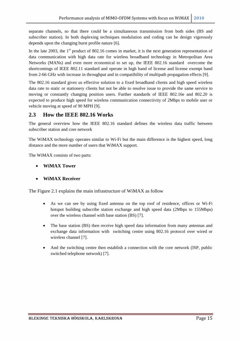
The Figure 2.1 explains the main infrastructure of WiMAX as follow
As we can see by using fixed antenna on the top roof of residence, offices or Wi-Fi
hotspot building subscribe station exchange and high speed data (2Mbps to 155Mbps)
over the wireless channel with base station (BS) [7].
The base station (BS) then receive high speed data information from many antennas and
exchange data information with switching centre using 802.16 protocol over wired or
wireless channel [7].
And the switching centre then establish a connection with the core network (ISP, public
switched telephone network) [7].
Performance analysis of MIMO-OFDM Systems with focus on WiMAX 2010
Blekinge Tekniska Högskola, KarlsKrona Page 16
Figure 2.1: WiMAX infrastructure [7]
2.4 Fading
The signals travelling in wireless link, its power vary due to the channel response. If the power of the
transmitted signals fluctuates considerably (drop down) under this scenario the channel is said to be
faded channel.
Fading can be define as
The modulated signal face deviation of attenuation, while propagated through wireless
channel due to response of channel.
Changeable, irregular and random change in magnitude and phase.
Fading is a result of different reasons like multi path fading, interference, shadowing, path loss etc.
The time slide for which the signal behavior is coherent and phase of signal on average is predictable
is said to be Coherence time [10-11].
So when the coherence time of propagation channel is higher than the delay profile of the channel and
fading is due to shadowing, amplitude and phase variation, if this variation is constant over the whole
period of use that‘s called slow fading. While on the other hand fast fading means change in amplitude
and phase forced by channel varies considerably, it occurs when the coherence time is smaller than the
delay constrained of the channel [11-12].
The frequency selective fading means that the transmitted signal‘s bandwidth is larger than coherence
bandwidth, and all the frequencies along signal bandwidth suffer the uncorrelated fading. Due to the
dispersive nature of the channel in urban environment the modulated signal encountered with
Frequency selective fading [11, 13].
2.5 The propagation of wireless Channels
The radio propagation means a signal transmission from transmitter to receiver on a wireless link or
radio link, the wireless channels and modeling of wireless channels is remain a difficult issue in the
field of research and designing. There are different kinds of radio propagations which are as follows
Ground wave propagation
Performance analysis of MIMO-OFDM Systems with focus on WiMAX 2010
Blekinge Tekniska Högskola, KarlsKrona Page 17
Sky wave propagation
Line of sight propagation
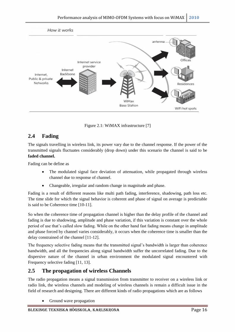
2.5.1 The Ground wave propogation
Figure 2.2, shows the Ground wave propagations in which we see the waves are propagated at a large
distance and follow the arc or curvature of the earth. It induces the current to the surface of earth. It is
considered for 2MHz frequency. If any obstacle occurred between the paths of transmitter and
receiver, diffraction of propagated signal may occur. Its example is AM radio [72].
Figure 2.2: Ground wave propagation [72]
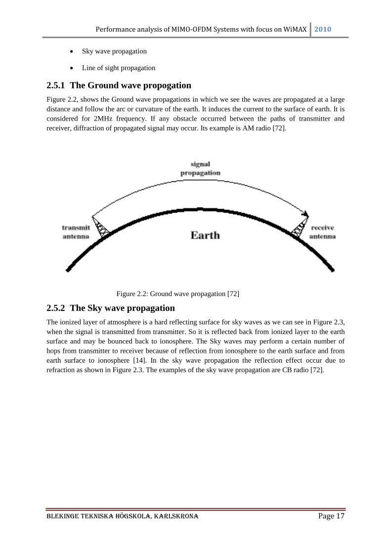
2.5.2 The Sky wave propagation
The ionized layer of atmosphere is a hard reflecting surface for sky waves as we can see in Figure 2.3,
when the signal is transmitted from transmitter. So it is reflected back from ionized layer to the earth
surface and may be bounced back to ionosphere. The Sky waves may perform a certain number of
hops from transmitter to receiver because of reflection from ionosphere to the earth surface and from
earth surface to ionosphere [14]. In the sky wave propagation the reflection effect occur due to
refraction as shown in Figure 2.3. The examples of the sky wave propagation are CB radio [72].
Performance analysis of MIMO-OFDM Systems with focus on WiMAX 2010
Blekinge Tekniska Högskola, KarlsKrona Page 18
Figure 2.3: Sky wave propagation [72]
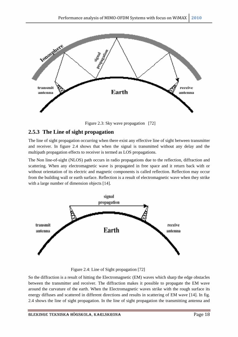
2.5.3 The Line of sight propagation
The line of sight propagation occurring when there exist any effective line of sight between transmitter
and receiver. In figure 2.4 shows that when the signal is transmitted without any delay and the
multipath propagation effects to receiver is termed as LOS propagations.
The Non line-of-sight (NLOS) path occurs in radio propagations due to the reflection, diffraction and
scattering. When any electromagnetic wave is propagated in free space and it return back with or
without orientation of its electric and magnetic components is called reflection. Reflection may occur
from the building wall or earth surface. Reflection is a result of electromagnetic wave when they strike
with a large number of dimension objects [14].
Figure 2.4: Line of Sight propagation [72]
So the diffraction is a result of hitting the Electromagnetic (EM) waves which sharp the edge obstacles
between the transmitter and receiver. The diffraction makes it possible to propagate the EM wave
around the curvature of the earth. When the Electromagnetic waves strike with the rough surface its
energy diffuses and scattered in different directions and results in scattering of EM wave [14]. In fig.
2.4 shows the line of sight propagation. In the line of sight propagation the transmitting antenna and
Performance analysis of MIMO-OFDM Systems with focus on WiMAX 2010
Blekinge Tekniska Högskola, KarlsKrona Page 19
the receiving antenna must be within the line of sight. In satellite communication the signal above 30
MHz is not reflected by ionosphere [72].
Performance analysis of MIMO-OFDM Systems with focus on WiMAX 2010
Blekinge Tekniska Högskola, KarlsKrona Page 20
CHAPTER 3: Multi Carrier Modulation
3.1 Multi-Carrier Modulation
With the development of portable systems and VLSI (very large scale integration), the high data rate is
an intensive demand for mobile and wireless applications from few kb/s to certain high value in Mb/s
with guaranteed quality of services (QoS).
In order to accommodate a high data rate over radio link many issues occurred which is relevant to the
wireless propagation e.g. multipath propagation, delay profile of a channel, fading ,ISI (inter symbol
inference) and shadowing etc. At a particular stage answer to these issues is an adaptive equalization at
a receiver end in order to manage with limitation of limited bandwidth, multi-cellular approach,
power, size and complexities at receiver. The adaptive equalization is not a good candidate. In current
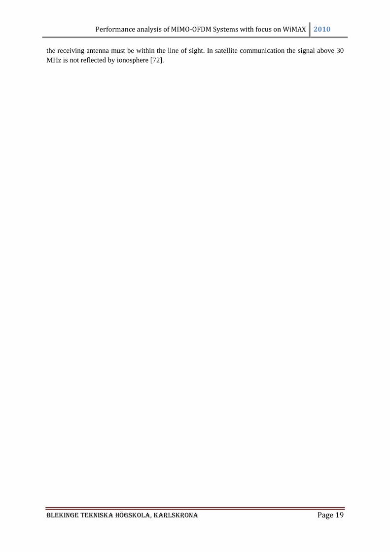
research it is shown that the promising candidate is OFDM (orthogonal frequency division
multiplexing), also called as multicarrier modulation scheme [15].
Figure 3.1: Multipath propagation and delay representation [73]
In figure 3.1 shows the multipath propagation when the signal transmit from the transmitter and
received by the receive antenna, there are two ways to receive by the receiver one is without delay and
the other first strike with the building and then receive by the receiver which occur due to delay [73].
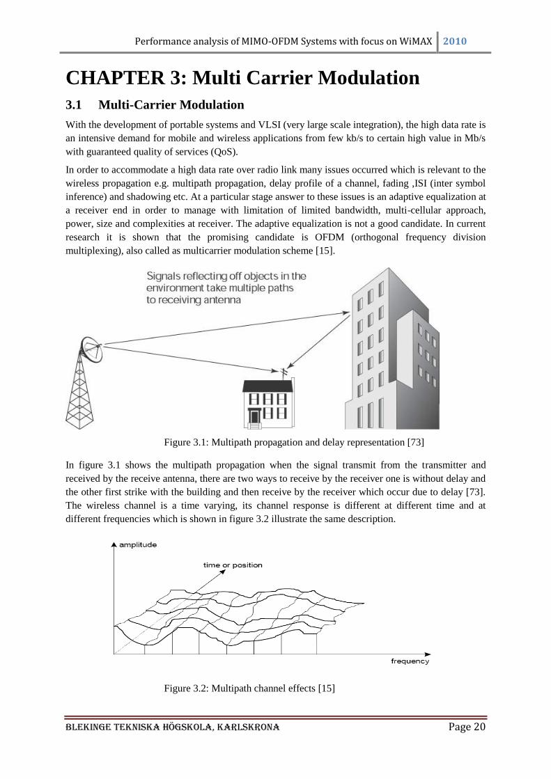
The wireless channel is a time varying, its channel response is different at different time and at
different frequencies which is shown in figure 3.2 illustrate the same description.
Figure 3.2: Multipath channel effects [15]
Performance analysis of MIMO-OFDM Systems with focus on WiMAX 2010
Blekinge Tekniska Högskola, KarlsKrona Page 21
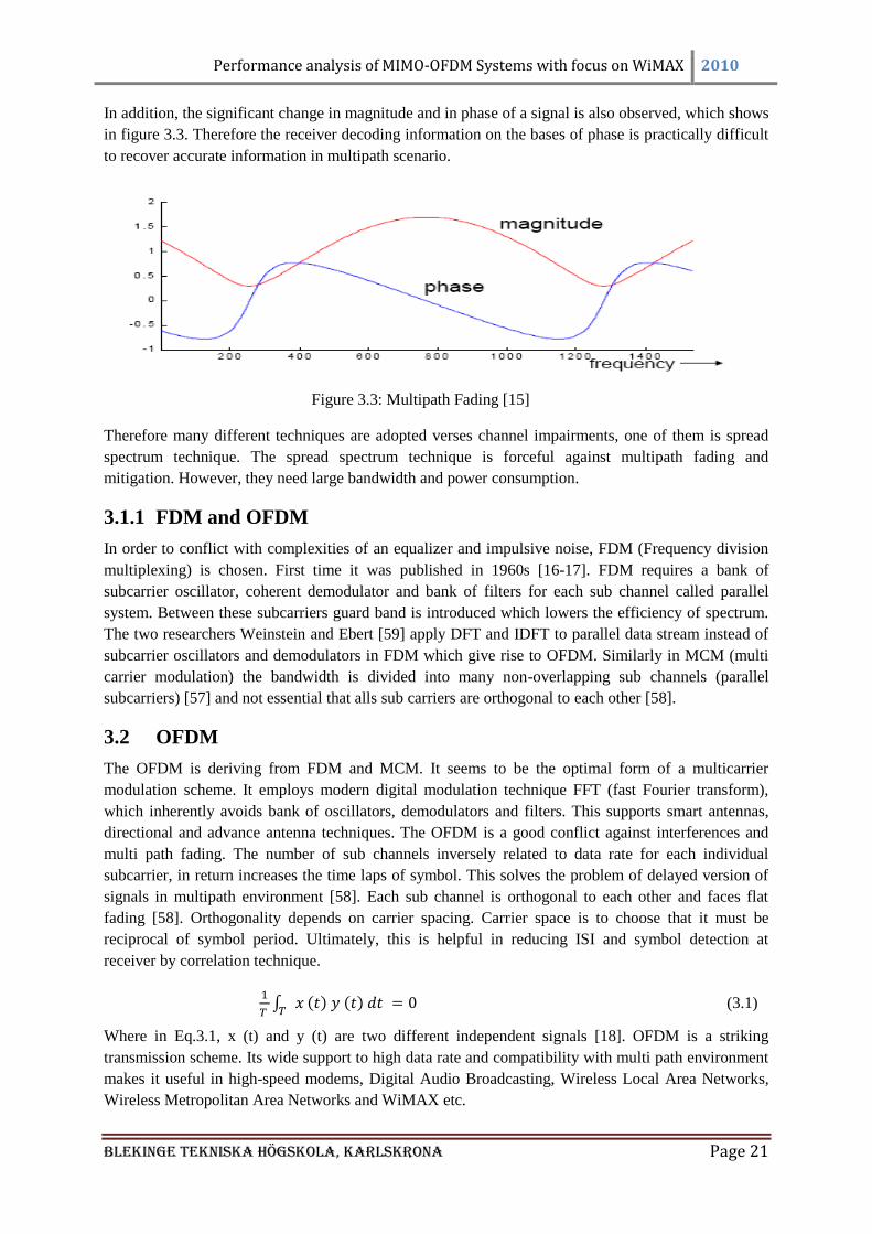
In addition, the significant change in magnitude and in phase of a signal is also observed, which shows
in figure 3.3. Therefore the receiver decoding information on the bases of phase is practically difficult
to recover accurate information in multipath scenario.
Figure 3.3: Multipath Fading [15]
Therefore many different techniques are adopted verses channel impairments, one of them is spread
spectrum technique. The spread spectrum technique is forceful against multipath fading and
mitigation. However, they need large bandwidth and power consumption.
3.1.1 FDM and OFDM
In order to conflict with complexities of an equalizer and impulsive noise, FDM (Frequency division
multiplexing) is chosen. First time it was published in 1960s [16-17]. FDM requires a bank of
subcarrier oscillator, coherent demodulator and bank of filters for each sub channel called parallel
system. Between these subcarriers guard band is introduced which lowers the efficiency of spectrum.
The two researchers Weinstein and Ebert [59] apply DFT and IDFT to parallel data stream instead of
subcarrier oscillators and demodulators in FDM which give rise to OFDM. Similarly in MCM (multi
carrier modulation) the bandwidth is divided into many non-overlapping sub channels (parallel
subcarriers) [57] and not essential that alls sub carriers are orthogonal to each other [58].
3.2 OFDM
The OFDM is deriving from FDM and MCM. It seems to be the optimal form of a multicarrier
modulation scheme. It employs modern digital modulation technique FFT (fast Fourier transform),
which inherently avoids bank of oscillators, demodulators and filters. This supports smart antennas,
directional and advance antenna techniques. The OFDM is a good conflict against interferences and
multi path fading. The number of sub channels inversely related to data rate for each individual
subcarrier, in return increases the time laps of symbol. This solves the problem of delayed version of
signals in multipath environment [58]. Each sub channel is orthogonal to each other and faces flat
fading [58]. Orthogonality depends on carrier spacing. Carrier space is to choose that it must be
reciprocal of symbol period. Ultimately, this is helpful in reducing ISI and symbol detection at
receiver by correlation technique.
(3.1)
Where in Eq.3.1, x (t) and y (t) are two different independent signals [18]. OFDM is a striking
transmission scheme. Its wide support to high data rate and compatibility with multi path environment
makes it useful in high-speed modems, Digital Audio Broadcasting, Wireless Local Area Networks,
Wireless Metropolitan Area Networks and WiMAX etc.
Performance analysis of MIMO-OFDM Systems with focus on WiMAX 2010
Blekinge Tekniska Högskola, KarlsKrona Page 22
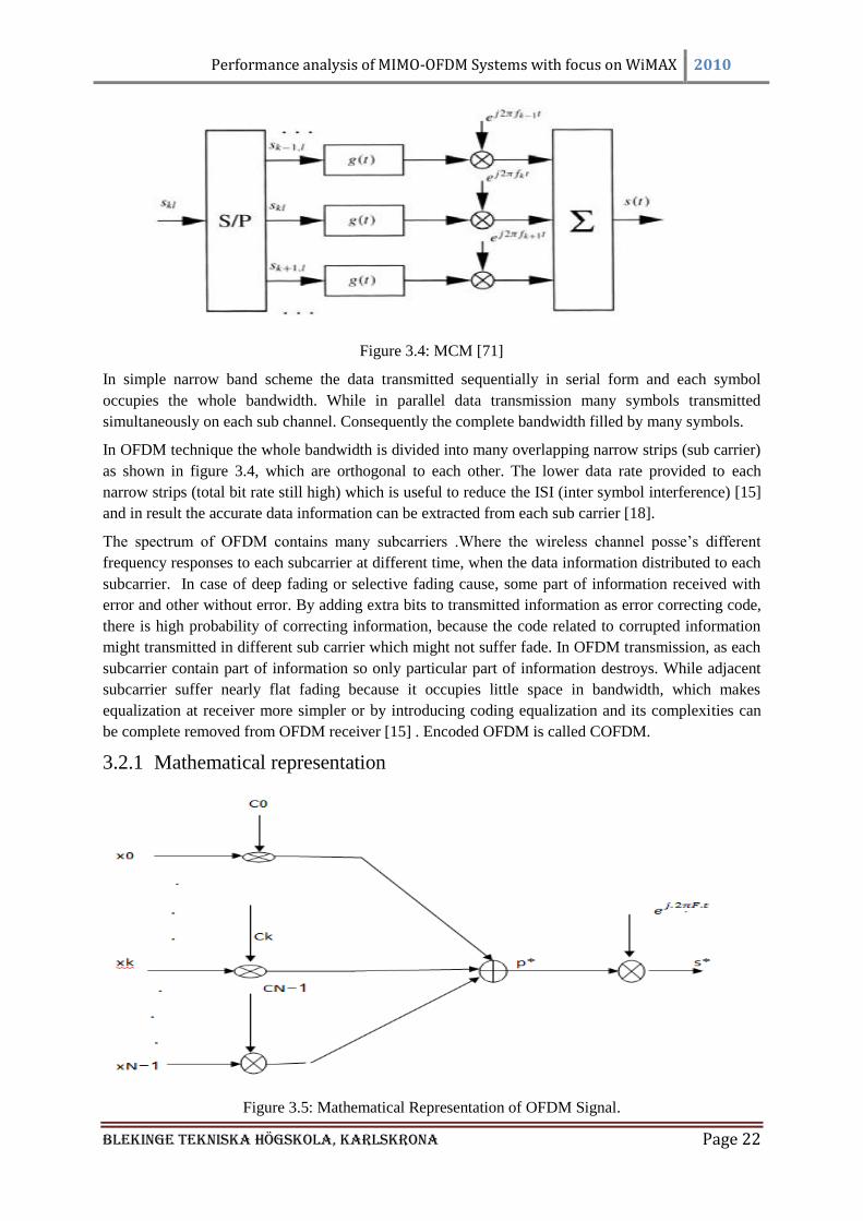
Figure 3.4: MCM [71]
In simple narrow band scheme the data transmitted sequentially in serial form and each symbol
occupies the whole bandwidth. While in parallel data transmission many symbols transmitted
simultaneously on each sub channel. Consequently the complete bandwidth filled by many symbols.
In OFDM technique the whole bandwidth is divided into many overlapping narrow strips (sub carrier)
as shown in figure 3.4, which are orthogonal to each other. The lower data rate provided to each
narrow strips (total bit rate still high) which is useful to reduce the ISI (inter symbol interference) [15]
and in result the accurate data information can be extracted from each sub carrier [18].
The spectrum of OFDM contains many subcarriers .Where the wireless channel posse‘s different
frequency responses to each subcarrier at different time, when the data information distributed to each
subcarrier. In case of deep fading or selective fading cause, some part of information received with
error and other without error. By adding extra bits to transmitted information as error correcting code,
there is high probability of correcting information, because the code related to corrupted information
might transmitted in different sub carrier which might not suffer fade. In OFDM transmission, as each
subcarrier contain part of information so only particular part of information destroys. While adjacent
subcarrier suffer nearly flat fading because it occupies little space in bandwidth, which makes
equalization at receiver more simpler or by introducing coding equalization and its complexities can
be complete removed from OFDM receiver [15] . Encoded OFDM is called COFDM.
3.2.1 Mathematical representation
Figure 3.5: Mathematical Representation of OFDM Signal.
Performance analysis of MIMO-OFDM Systems with focus on WiMAX 2010
Blekinge Tekniska Högskola, KarlsKrona Page 23
(3.2)
(3.3)
(3.4)
i.e
and
(3.5)
Where in Eq. 3.5, and is the output signal and its magnitude. Let us assuming amplitude
of a carrier signal is equal to 1 and phase is represented by ck, for symbol period ck the amplitude and
phase will not change, for every symbol values of ck would be different. The total number of
subcarriers available is N. In order to main orthogonality sinc-shaped pulses are use to define
subcarriers in frequency domain. A Sinc-shaped pulse chooses so as it zero crossing occurs at the 1/T
and multiple of 1/T. From equation above ―fi‖ is centre of carrier frequency and ―fc‖ is main carrier
frequency. Maximum value of each sub carrier spectra occurs at its own frequency and zero on the
centre of adjacent subcarrier frequencies.
3.2.2 Fourier Transform
Fourier transform is a mathematical tool to convert the signal from time domain to frequency domain,
or from frequency domain to time domain, one of the famous and practice technique of Fourier
transform is DFT(discrete Fourier transform), which samples the signal in both temporal and
frequency domain .
FFT (Fast Fourier transform) is fast and efficient method of DFT used by computer application for
analysis and signal manipulation. In OFDM in coming serial bits of information, data is reshape in to
parallel form from serial form. Group the data bits in appropriate size according to design of OFDM
and convert in to complex number. Complex number is then modulated using IFFT (inverse fast
Fourier transform ) in base band then reshape again from parallel to serial for transmission[15, 18].
Zeros are pad at the end and start of composite spectrum of subcarriers, to avoid interferences between
next and previous composite spectrum.
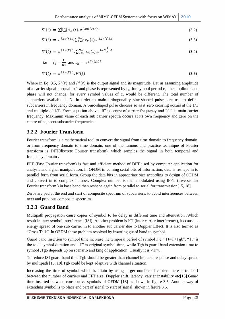
3.2.3 Guard Band
Multipath propagation cause copies of symbol to be delay in different time and attenuation .Which
result in inter symbol interference (ISI). Another problem is ICI (inter carrier interference), its cause is
energy spread of one sub carrier in to another sub carrier due to Doppler Effect. It is also termed as
―Cross Talk‖. In OFDM these problem resolved by inserting guard band to symbol.
Guard band insertion to symbol time increase the temporal period of symbol .i.e. ―Tt=T+Tgb‖. ―Tt‖ is
the total symbol duration and ―T‖ is original symbol time, while Tgb is guard band extension time to
symbol .Tgb depends up on scenario and king of application. Usually it is <T/4.
To reduce ISI guard band time Tgb should be greater than channel impulse response and delay spread
by multipath [15, 18].Tgb could be kept adaptive with channel situation.
Increasing the time of symbol which is attain by using larger number of carrier, there is tradeoff
between the number of carriers and FFT size, Doppler shift, latency, carrier instability etc[15].Guard
time inserted between consecutive symbols of OFDM [18] as shown in figure 3.5. Another way of
extending symbol is to place end part of signal to start of signal, shown in figure 3.6.
Performance analysis of MIMO-OFDM Systems with focus on WiMAX 2010
Blekinge Tekniska Högskola, KarlsKrona Page 24
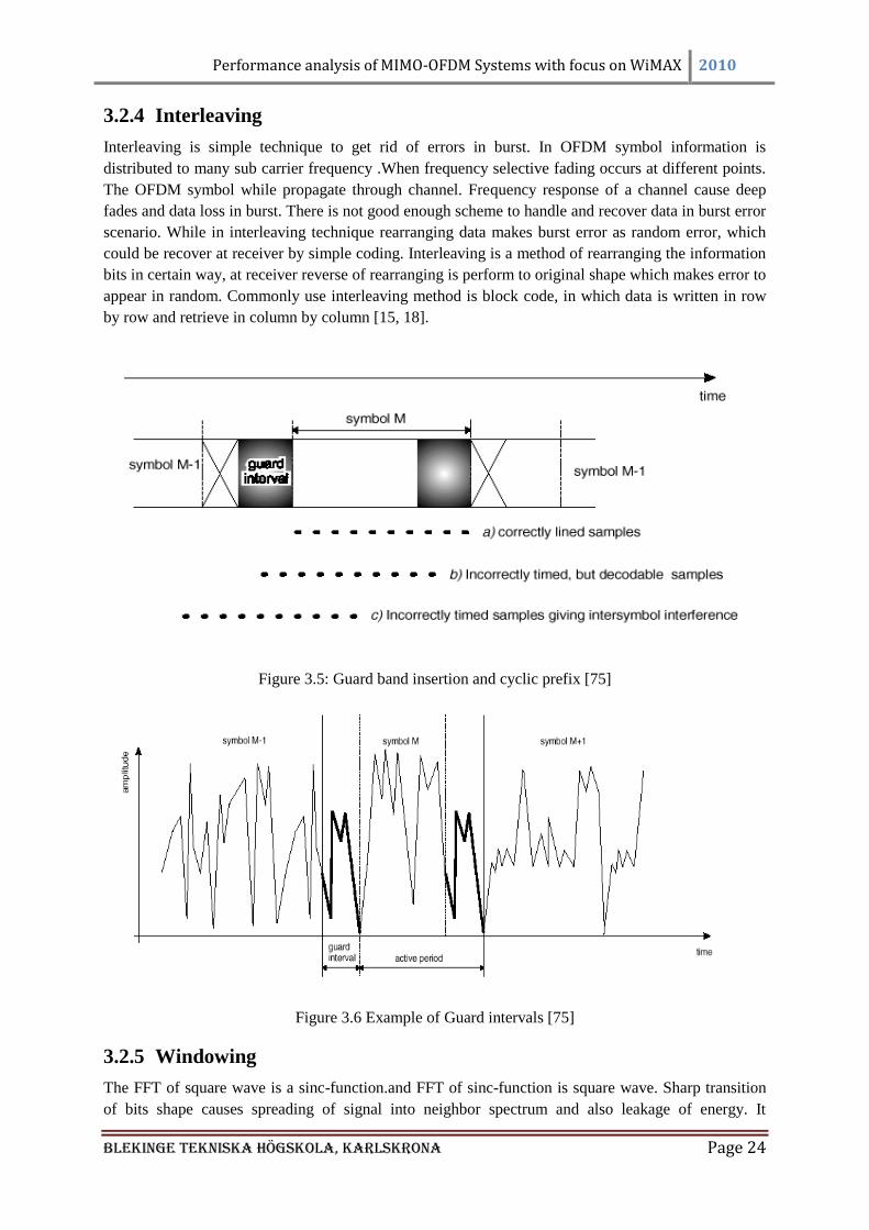
3.2.4 Interleaving
Interleaving is simple technique to get rid of errors in burst. In OFDM symbol information is
distributed to many sub carrier frequency .When frequency selective fading occurs at different points.
The OFDM symbol while propagate through channel. Frequency response of a channel cause deep
fades and data loss in burst. There is not good enough scheme to handle and recover data in burst error
scenario. While in interleaving technique rearranging data makes burst error as random error, which
could be recover at receiver by simple coding. Interleaving is a method of rearranging the information
bits in certain way, at receiver reverse of rearranging is perform to original shape which makes error to
appear in random. Commonly use interleaving method is block code, in which data is written in row
by row and retrieve in column by column [15, 18].
Figure 3.5: Guard band insertion and cyclic prefix [75]
Figure 3.6 Example of Guard intervals [75]
3.2.5 Windowing
The FFT of square wave is a sinc-function.and FFT of sinc-function is square wave. Sharp transition
of bits shape causes spreading of signal into neighbor spectrum and also leakage of energy. It
Performance analysis of MIMO-OFDM Systems with focus on WiMAX 2010
Blekinge Tekniska Högskola, KarlsKrona Page 25
decreases slowly according to sinc function and goes out of band spectrum. Windowing is another
technique which causes symbol or signal to decrease sharply in order to reside in spectrum.
Windowing is performed on each single OFDM symbol. Time wave form is truncated by windowing
scheme to make single OFDM symbol. Optimum windowing scheme is raised cosine windowing
technique, it accommodate channel bandwidth from certain minimum value(R/2) to certain maximum
value(R) [18].
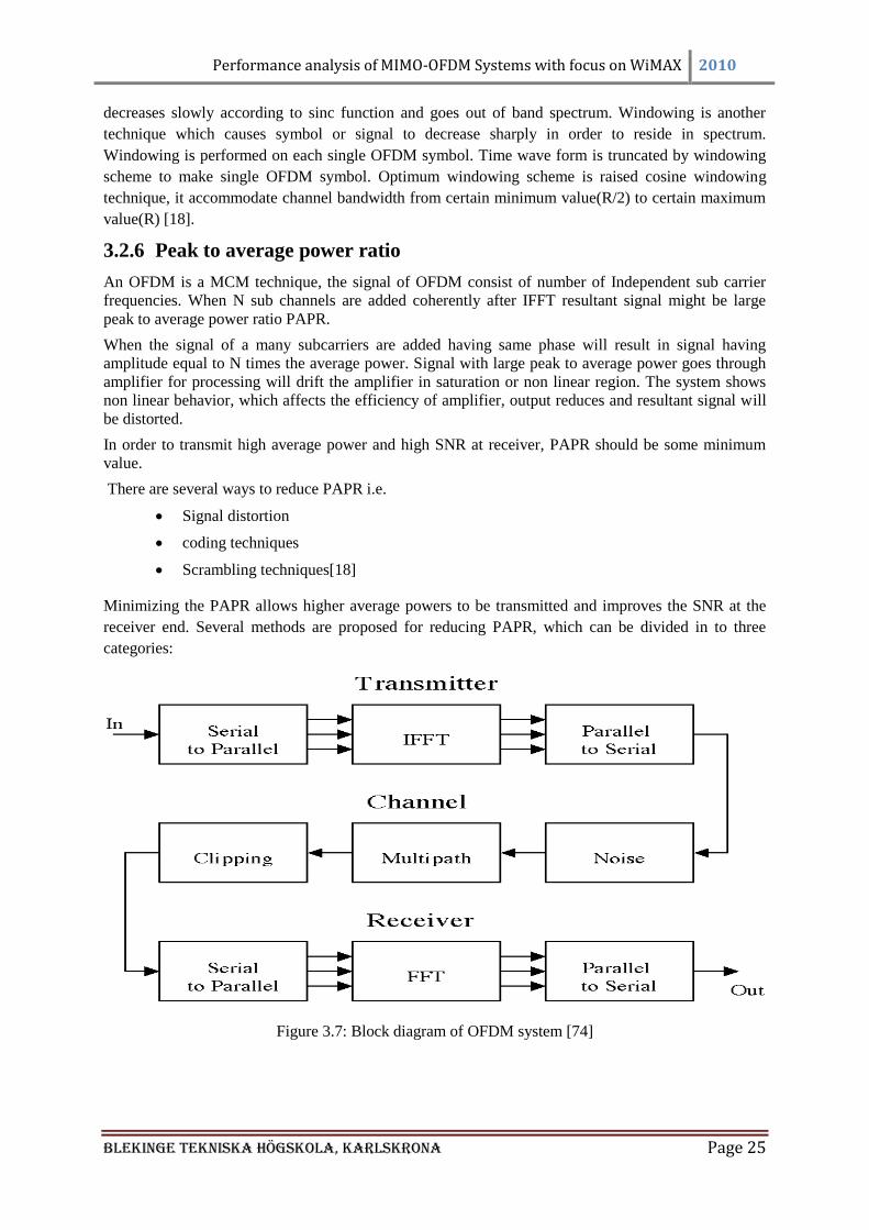
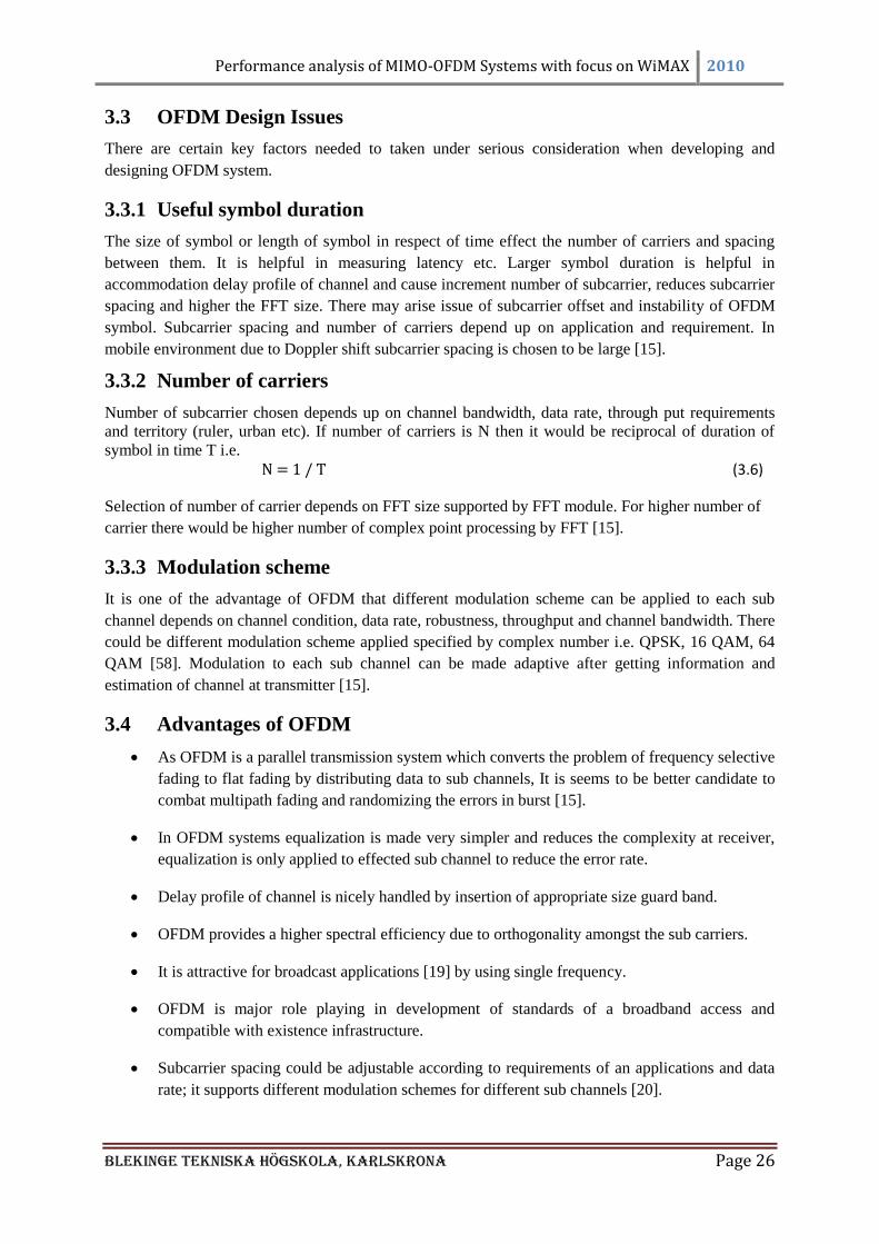
3.2.6 Peak to average power ratio
An OFDM is a MCM technique, the signal of OFDM consist of number of Independent sub carrier
frequencies. When N sub channels are added coherently after IFFT resultant signal might be large
peak to average power ratio PAPR.
When the signal of a many subcarriers are added having same phase will result in signal having
amplitude equal to N times the average power. Signal with large peak to average power goes through
amplifier for processing will drift the amplifier in saturation or non linear region. The system shows
non linear behavior, which affects the efficiency of amplifier, output reduces and resultant signal will
be distorted.
In order to transmit high average power and high SNR at receiver, PAPR should be some minimum
value.
There are several ways to reduce PAPR i.e.
Signal distortion
coding techniques
Scrambling techniques[18]
Minimizing the PAPR allows higher average powers to be transmitted and improves the SNR at the
receiver end. Several methods are proposed for reducing PAPR, which can be divided in to three
categories:
Figure 3.7: Block diagram of OFDM system [74]
Performance analysis of MIMO-OFDM Systems with focus on WiMAX 2010
Blekinge Tekniska Högskola, KarlsKrona Page 26
3.3 OFDM Design Issues
There are certain key factors needed to taken under serious consideration when developing and
designing OFDM system.
3.3.1 Useful symbol duration
The size of symbol or length of symbol in respect of time effect the number of carriers and spacing
between them. It is helpful in measuring latency etc. Larger symbol duration is helpful in
accommodation delay profile of channel and cause increment number of subcarrier, reduces subcarrier
spacing and higher the FFT size. There may arise issue of subcarrier offset and instability of OFDM
symbol. Subcarrier spacing and number of carriers depend up on application and requirement. In
mobile environment due to Doppler shift subcarrier spacing is chosen to be large [15].
3.3.2 Number of carriers
Number of subcarrier chosen depends up on channel bandwidth, data rate, through put requirements
and territory (ruler, urban etc). If number of carriers is N then it would be reciprocal of duration of
symbol in time T i.e.
(3.6)
Selection of number of carrier depends on FFT size supported by FFT module. For higher number of
carrier there would be higher number of complex point processing by FFT [15].
3.3.3 Modulation scheme
It is one of the advantage of OFDM that different modulation scheme can be applied to each sub
channel depends on channel condition, data rate, robustness, throughput and channel bandwidth. There
could be different modulation scheme applied specified by complex number i.e. QPSK, 16 QAM, 64
QAM [58]. Modulation to each sub channel can be made adaptive after getting information and
estimation of channel at transmitter [15].
3.4 Advantages of OFDM
As OFDM is a parallel transmission system which converts the problem of frequency selective
fading to flat fading by distributing data to sub channels, It is seems to be better candidate to
combat multipath fading and randomizing the errors in burst [15].
In OFDM systems equalization is made very simpler and reduces the complexity at receiver,
equalization is only applied to effected sub channel to reduce the error rate.
Delay profile of channel is nicely handled by insertion of appropriate size guard band.
OFDM provides a higher spectral efficiency due to orthogonality amongst the sub carriers.
It is attractive for broadcast applications [19] by using single frequency.
OFDM is major role playing in development of standards of a broadband access and
compatible with existence infrastructure.
Subcarrier spacing could be adjustable according to requirements of an applications and data
rate; it supports different modulation schemes for different sub channels [20].
Performance analysis of MIMO-OFDM Systems with focus on WiMAX 2010
Blekinge Tekniska Högskola, KarlsKrona Page 27
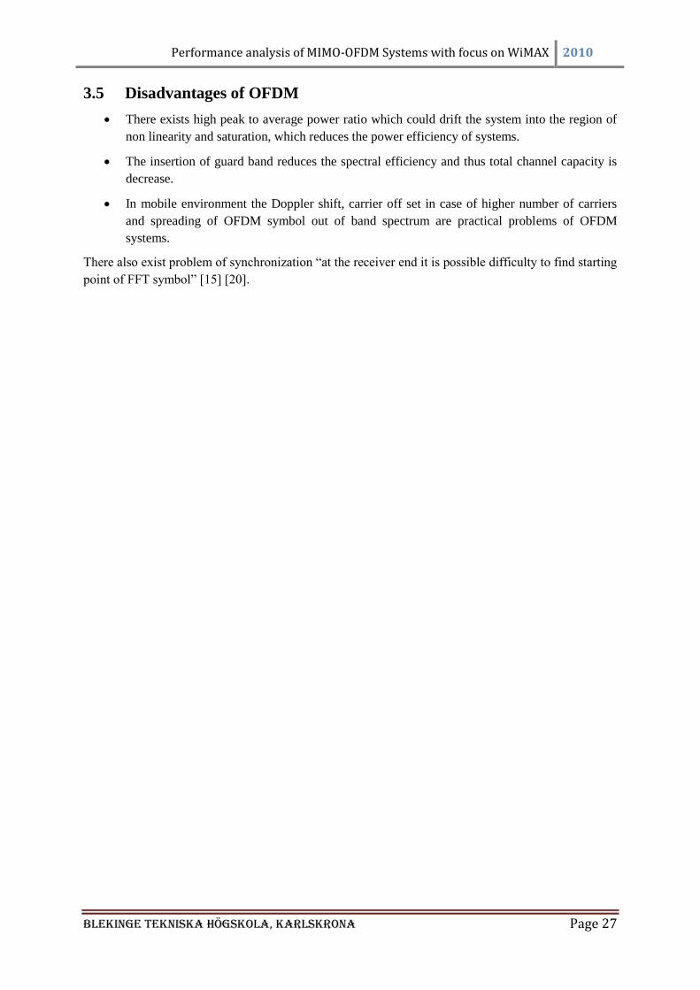
3.5 Disadvantages of OFDM
There exists high peak to average power ratio which could drift the system into the region of
non linearity and saturation, which reduces the power efficiency of systems.
The insertion of guard band reduces the spectral efficiency and thus total channel capacity is
decrease.
In mobile environment the Doppler shift, carrier off set in case of higher number of carriers
and spreading of OFDM symbol out of band spectrum are practical problems of OFDM
systems.
There also exist problem of synchronization ―at the receiver end it is possible difficulty to find starting
point of FFT symbol‖ [15] [20].
Performance analysis of MIMO-OFDM Systems with focus on WiMAX 2010
Blekinge Tekniska Högskola, KarlsKrona Page 28
CHAPTER 4: Multiple Input Multiple Output
4.1 MIMO Systems
The multipath propagation is vital characteristic of data transmission in wireless communication
systems. Wireless channel contains different impairment to transmitted signal and channel response. It
affects the signal to travel in multipath between transmitter and receiver. The receiver gets the
reflection of same symbols in delay versions. Delays or fading occurs due to reflection, refractions,
diffractions, shadowing etc. Because of buildings, trees, aircrafts, humidity, temperature etc. Delay or
fading could be in result of changing phase or magnitude of signals. The multipath affects and delay
profile reduce the channel efficiency, through put and cause corrupted information at receiver.
Intelligently multipath effect of MIMO is used to increase capacity of system.
In Rayleigh fading signal travels through different paths and considered to be follow independent
behavior in every path, phase is uniformly distributed between 0 to 2 and magnitude vary
randomly[21]. While in Rician fading the line of sight (LOS) exists i.e. one of the paths to receiver is
much stronger than other one [22]. A signal or symbol of delay version have change in phase or differ
in phase with line of sight signal phase. Crust and trough of both these signals cause resultant signal to
be high average power or attenuated. So in result we may get distorted signal at receiver end.
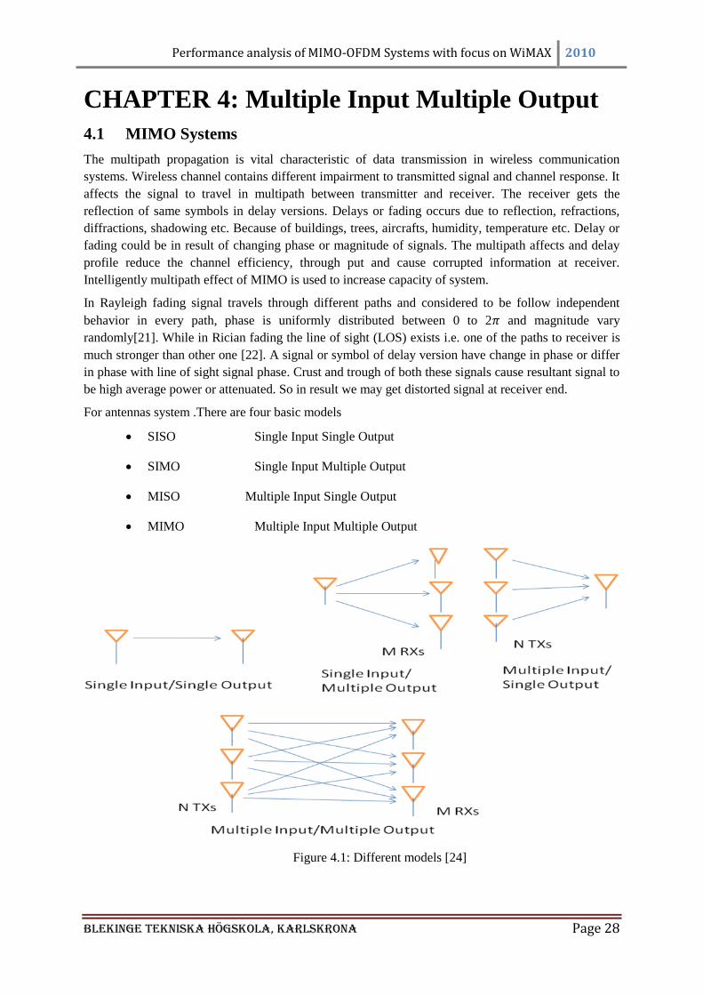
For antennas system .There are four basic models
SISO Single Input Single Output
SIMO Single Input Multiple Output
MISO Multiple Input Single Output
MIMO Multiple Input Multiple Output
Figure 4.1: Different models [24]
Performance analysis of MIMO-OFDM Systems with focus on WiMAX 2010
Blekinge Tekniska Högskola, KarlsKrona Page 29
4.2 Channel Capacity
The most recent research on Shannon capacity for single antenna system and multi antennas system
has shown that there is enormous channel capacity could be attain from MIMO systems. Its depends
up on different scenarios, like channel fading, knowledge of channel, the impulse response of channel
quality and quantity of knowledge about channel to receiver and transmitter or either of one and
channel correlation gain on either antenna elements[23]. Channel capacity for different antenna
models can be seen and analyze by following.
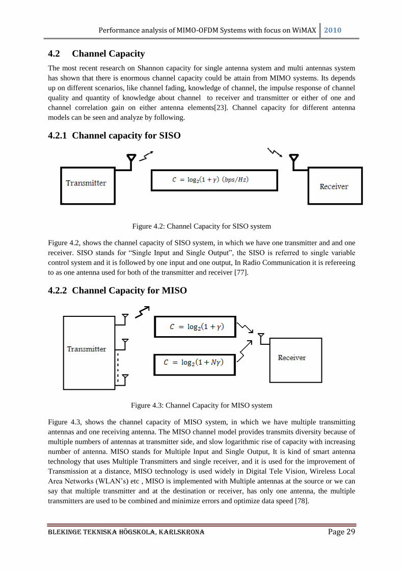
4.2.1 Channel capacity for SISO
Figure 4.2: Channel Capacity for SISO system
Figure 4.2, shows the channel capacity of SISO system, in which we have one transmitter and and one
receiver. SISO stands for ―Single Input and Single Output‖, the SISO is referred to single variable
control system and it is followed by one input and one output, In Radio Communication it is refereeing
to as one antenna used for both of the transmitter and receiver [77].
4.2.2 Channel Capacity for MISO
Figure 4.3: Channel Capacity for MISO system
Figure 4.3, shows the channel capacity of MISO system, in which we have multiple transmitting
antennas and one receiving antenna. The MISO channel model provides transmits diversity because of
multiple numbers of antennas at transmitter side, and slow logarithmic rise of capacity with increasing
number of antenna. MISO stands for Multiple Input and Single Output, It is kind of smart antenna
technology that uses Multiple Transmitters and single receiver, and it is used for the improvement of
Transmission at a distance, MISO technology is used widely in Digital Tele Vision, Wireless Local
Area Networks (WLAN‘s) etc , MISO is implemented with Multiple antennas at the source or we can
say that multiple transmitter and at the destination or receiver, has only one antenna, the multiple
transmitters are used to be combined and minimize errors and optimize data speed [78].
Performance analysis of MIMO-OFDM Systems with focus on WiMAX 2010
Blekinge Tekniska Högskola, KarlsKrona Page 30
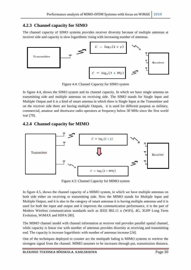
4.2.3 Channel capacity for SIMO
The channel capacity of SIMO systems provides receiver diversity because of multiple antennas at
receiver side and capacity is slow logarithmic rising with increasing number of antennas.
Figure 4.4: Channel Capacity for SIMO system
In figure 4.4, shows the SIMO system and its channel capacity. In which we have single antenna on
transmitting side and multiple antennas on receiving side. The SIMO stands for Single Input and
Multiple Output and it is a kind of smart antenna in which there is Single Input at the Transmitter and
on the receiver side there are having multiple Outputs, it is used for different purpose as military,
commercial, amateur and shortwave radio operators at frequency below 30 MHz since the first world
war [79].
4.2.4 Channel capacity for MIMO
Figure 4.5: Channel Capacity for MIMO system
In figure 4.5, shows the channel capacity of a MIMO system, in which we have multiple antennas on
both side either on receiving or transmitting side. Now the MIMO stands for Multiple Input and
Multiple Output, and it is also in the category of smart antennas it is having multiple antennas and it is
used for both the input and output and it improves the communication performance, it is the part of
Modern Wireless communication standards such as IEEE 802.11 n (WiFi), 4G, 3GPP Long Term
Evolution, WiMAX and HSPA [80].
The MIMO channel model with channel information at receiver end provides parallel spatial channel,
while capacity is linear rise with number of antennas provides diversity at receiving and transmitting
end. The capacity is increase logarithmic with number of antennas increase [24].
One of the techniques deployed to counter act the multipath fading is MIMO systems to retrieve the
strongest signal from the channel. MIMO assumes to be increases through put, transmission distance,
Performance analysis of MIMO-OFDM Systems with focus on WiMAX 2010
Blekinge Tekniska Högskola, KarlsKrona Page 31
coverage area, BER improvement and reliability of transmission in multipath propagation. MIMO
systems is sending and receiving multiple signals simultaneously. So it is better support to diversity.
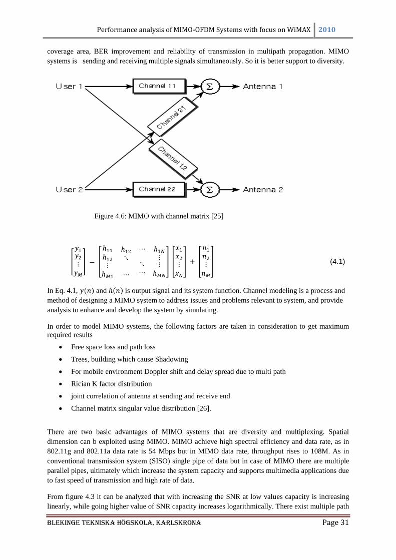
Figure 4.6: MIMO with channel matrix [25]
(4.1)
In Eq. 4.1, and is output signal and its system function. Channel modeling is a process and
method of designing a MIMO system to address issues and problems relevant to system, and provide
analysis to enhance and develop the system by simulating.
In order to model MIMO systems, the following factors are taken in consideration to get maximum
required results
Free space loss and path loss
Trees, building which cause Shadowing
For mobile environment Doppler shift and delay spread due to multi path
Rician K factor distribution
joint correlation of antenna at sending and receive end
Channel matrix singular value distribution [26].
There are two basic advantages of MIMO systems that are diversity and multiplexing. Spatial
dimension can b exploited using MIMO. MIMO achieve high spectral efficiency and data rate, as in
802.11g and 802.11a data rate is 54 Mbps but in MIMO data rate, throughput rises to 108M. As in
conventional transmission system (SISO) single pipe of data but in case of MIMO there are multiple
parallel pipes, ultimately which increase the system capacity and supports multimedia applications due
to fast speed of transmission and high rate of data.
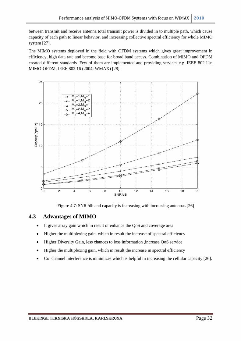
From figure 4.3 it can be analyzed that with increasing the SNR at low values capacity is increasing
linearly, while going higher value of SNR capacity increases logarithmically. There exist multiple path
Performance analysis of MIMO-OFDM Systems with focus on WiMAX 2010
Blekinge Tekniska Högskola, KarlsKrona Page 32
between transmit and receive antenna total transmit power is divided in to multiple path, which cause
capacity of each path to linear behavior, and increasing collective spectral efficiency for whole MIMO
system [27].
The MIMO systems deployed in the field with OFDM systems which gives great improvement in
efficiency, high data rate and become base for broad band access. Combination of MIMO and OFDM
created different standards. Few of them are implemented and providing services e.g. IEEE 802.11n
MIMO-OFDM, IEEE 802.16 (2004: WMAX) [28].
Figure 4.7: SNR /db and capacity is increasing with increasing antennas [26]
4.3 Advantages of MIMO
It gives array gain which in result of enhance the QoS and coverage area
Higher the multiplexing gain which in result the increase of spectral efficiency
Higher Diversity Gain, less chances to loss information ,increase QoS service
Higher the multiplexing gain, which in result the increase in spectral efficiency
Co–channel interference is minimizes which is helpful in increasing the cellular capacity [26].
Performance analysis of MIMO-OFDM Systems with focus on WiMAX 2010
Blekinge Tekniska Högskola, KarlsKrona Page 33
CHAPTER 5: Space Time Coding
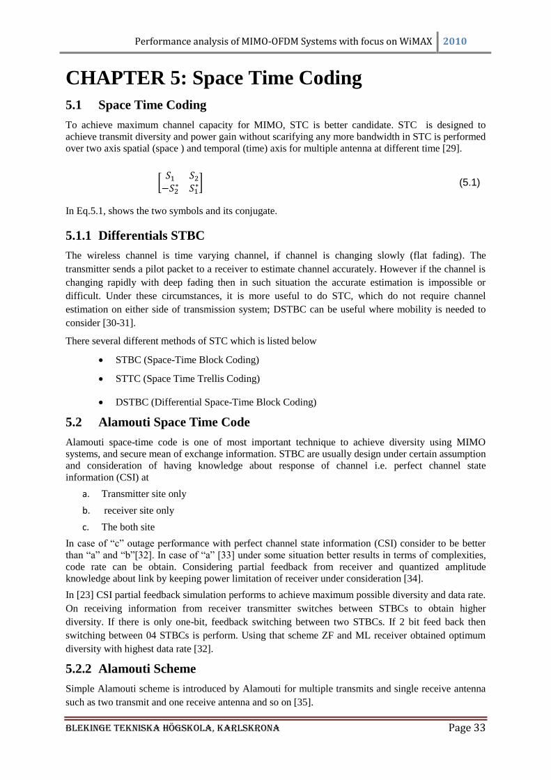
5.1 Space Time Coding
To achieve maximum channel capacity for MIMO, STC is better candidate. STC is designed to
achieve transmit diversity and power gain without scarifying any more bandwidth in STC is performed
over two axis spatial (space ) and temporal (time) axis for multiple antenna at different time [29].
(5.1)
In Eq.5.1, shows the two symbols and its conjugate.
5.1.1 Differentials STBC
The wireless channel is time varying channel, if channel is changing slowly (flat fading). The
transmitter sends a pilot packet to a receiver to estimate channel accurately. However if the channel is
changing rapidly with deep fading then in such situation the accurate estimation is impossible or
difficult. Under these circumstances, it is more useful to do STC, which do not require channel
estimation on either side of transmission system; DSTBC can be useful where mobility is needed to
consider [30-31].
There several different methods of STC which is listed below
STBC (Space-Time Block Coding)
STTC (Space Time Trellis Coding)
DSTBC (Differential Space-Time Block Coding)
5.2 Alamouti Space Time Code
Alamouti space-time code is one of most important technique to achieve diversity using MIMO
systems, and secure mean of exchange information. STBC are usually design under certain assumption
and consideration of having knowledge about response of channel i.e. perfect channel state
information (CSI) at
a. Transmitter site only
b. receiver site only
c. The both site
In case of ―c‖ outage performance with perfect channel state information (CSI) consider to be better
than ―a‖ and ―b‖[32]. In case of ―a‖ [33] under some situation better results in terms of complexities,
code rate can be obtain. Considering partial feedback from receiver and quantized amplitude
knowledge about link by keeping power limitation of receiver under consideration [34].
In [23] CSI partial feedback simulation performs to achieve maximum possible diversity and data rate.
On receiving information from receiver transmitter switches between STBCs to obtain higher
diversity. If there is only one-bit, feedback switching between two STBCs. If 2 bit feed back then
switching between 04 STBCs is perform. Using that scheme ZF and ML receiver obtained optimum
diversity with highest data rate [32].
5.2.2 Alamouti Scheme
Simple Alamouti scheme is introduced by Alamouti for multiple transmits and single receive antenna
such as two transmit and one receive antenna and so on [35].
Performance analysis of MIMO-OFDM Systems with focus on WiMAX 2010
Blekinge Tekniska Högskola, KarlsKrona Page 34
5.2.2.1 2×1 Alamouti Scheme
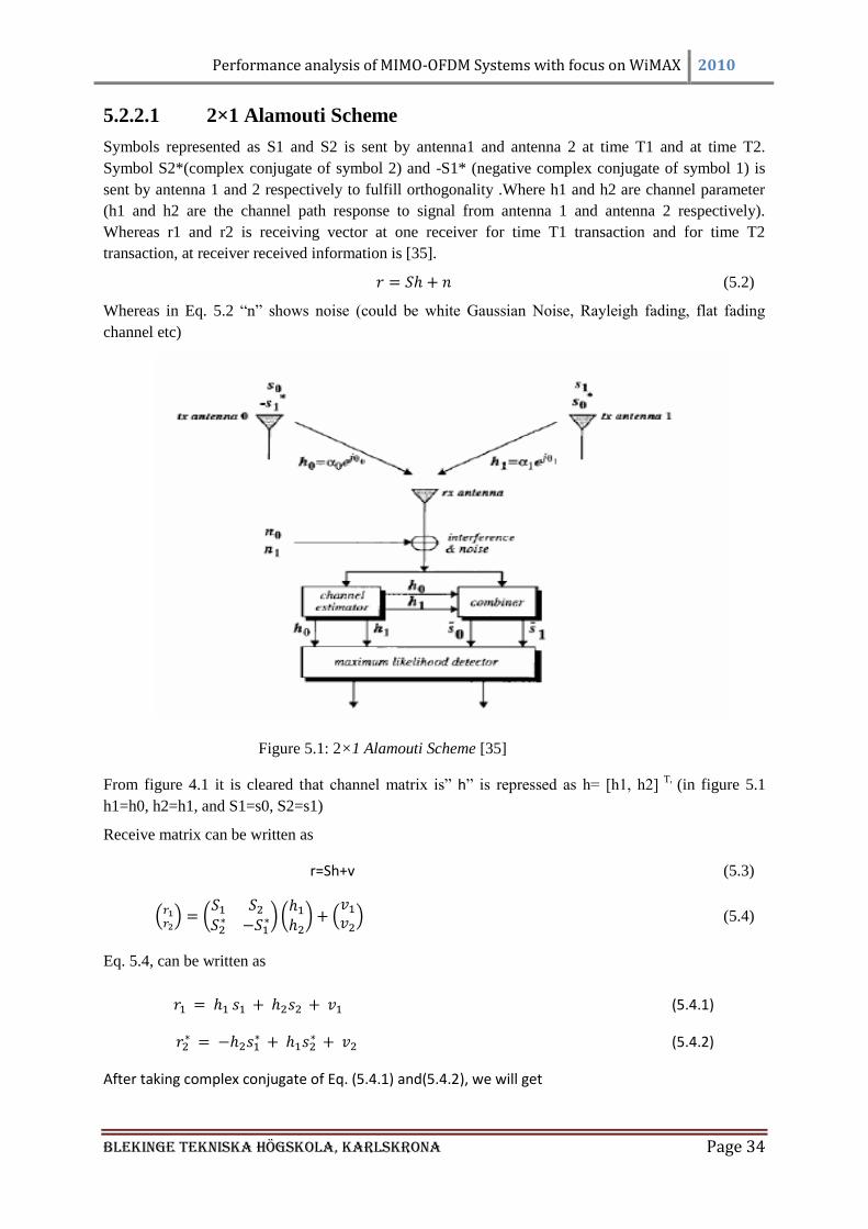
Symbols represented as S1 and S2 is sent by antenna1 and antenna 2 at time T1 and at time T2.
Symbol S2*(complex conjugate of symbol 2) and -S1* (negative complex conjugate of symbol 1) is
sent by antenna 1 and 2 respectively to fulfill orthogonality .Where h1 and h2 are channel parameter
(h1 and h2 are the channel path response to signal from antenna 1 and antenna 2 respectively).
Whereas r1 and r2 is receiving vector at one receiver for time T1 transaction and for time T2
transaction, at receiver received information is [35].
(5.2)
Whereas in Eq. 5.2 ―n‖ shows noise (could be white Gaussian Noise, Rayleigh fading, flat fading
channel etc)
Figure 5.1: 2×1 Alamouti Scheme [35]
From figure 4.1 it is cleared that channel matrix is‖ ‖ is repressed as h= [h1, h2] T,
(in figure 5.1
h1=h0, h2=h1, and S1=s0, S2=s1)
Receive matrix can be written as
(5.3)
(5.4)
Eq. 5.4, can be written as
(5.4.1)
(5.4.2)
After taking complex conjugate of Eq. (5.4.1) and(5.4.2), we will get
Performance analysis of MIMO-OFDM Systems with focus on WiMAX 2010
Blekinge Tekniska Högskola, KarlsKrona Page 35
(5.4.3)
(5.4.4)
In Matrix form it can be written as
(5.5)
Now channel matrix with symbols takes new mathematical shape i.e. given in Eq. 5.6.
Y = H + (5.6)
Where the rearrange channel matrix H is orthogonal, mathematically it can verified as
(5.7)
Where in Eq. 5.7, is the identity matrix of order and gain is
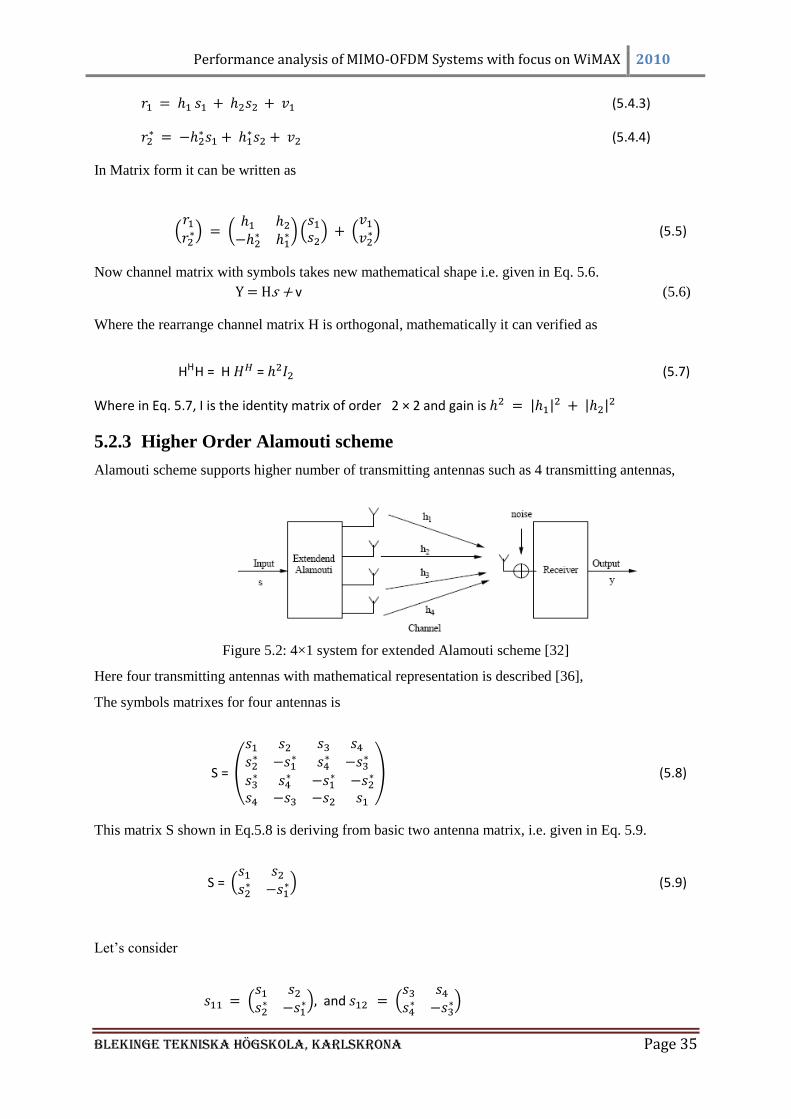
5.2.3 Higher Order Alamouti scheme
Alamouti scheme supports higher number of transmitting antennas such as 4 transmitting antennas,
Figure 5.2: 4×1 system for extended Alamouti scheme [32]
Here four transmitting antennas with mathematical representation is described [36],
The symbols matrixes for four antennas is
(5.8)
This matrix S shown in Eq.5.8 is deriving from basic two antenna matrix, i.e. given in Eq. 5.9.
(5.9)
Let‘s consider
and
Performance analysis of MIMO-OFDM Systems with focus on WiMAX 2010
Blekinge Tekniska Högskola, KarlsKrona Page 36
So Eq. 5.8, can be written as
(5.10)
For , in matrix form it can be written as,
(5.11)
Eq.5.11, In mathematical equation form it can be written as (neglecting noise)
(5.11.1)
–
–
(5.11.2)
(5.11.3)
(5.11.4)
For the effective channel matrix given in Eq.5.12, can be derived for four antennas by taking the
complex conjugate of Eq. (5.11.2) & (5.11.3), will get
(5.12)
Orthogonality of channel matrix can be verified as [35-36].
(5.13)
Where is the identity matrix of order 2x2 and is gain of channel
(5.14)
5.3 Feed Back Analysis
In feedback approach information signal (bit) is sent back to transmitter to train about channel
(selecting EASTBC at transmitter) in order to achieve best results [32].
Number of bits sent by receiver to transmitter enable transmitter to switch between numbers of
different STBCs (Number of STBCs is equal to number of bits feedback exponential of 2)
Performance analysis of MIMO-OFDM Systems with focus on WiMAX 2010
Blekinge Tekniska Högskola, KarlsKrona Page 37
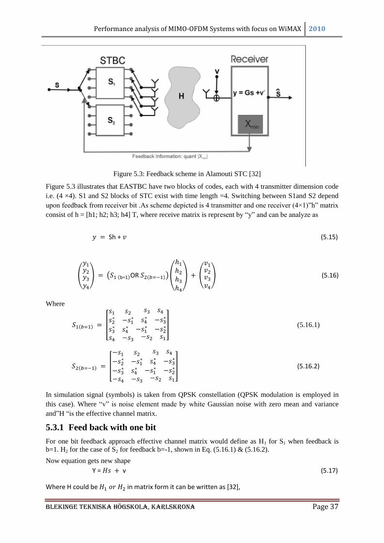
Figure 5.3: Feedback scheme in Alamouti STC [32]
Figure 5.3 illustrates that EASTBC have two blocks of codes, each with 4 transmitter dimension code
i.e. (4 ×4). S1 and S2 blocks of STC exist with time length =4. Switching between S1and S2 depend
upon feedback from receiver bit .As scheme depicted is 4 transmitter and one receiver (4×1)‖h‖ matrix
consist of h = [h1; h2; h3; h4] T, where receive matrix is represent by ―y‖ and can be analyze as
(5.15)
(5.16)
Where
(5.16.1)
(5.16.2)
In simulation signal (symbols) is taken from QPSK constellation (QPSK modulation is employed in
this case). Where ―v‖ is noise element made by white Gaussian noise with zero mean and variance
and‖H ―is the effective channel matrix.
5.3.1 Feed back with one bit
For one bit feedback approach effective channel matrix would define as H1 for S1 when feedback is
b=1. H2 for the case of S2 for feedback b=-1, shown in Eq. (5.16.1) & (5.16.2).
Now equation gets new shape
(5.17)
Where could be in matrix form it can be written as [32],

Performance analysis of MIMO-OFDM Systems with focus on WiMAX 2010
Blekinge Tekniska Högskola, KarlsKrona Page 38
-
(5.18)
Where is given below
(5.18.1)
(5.18.2)
The level of orthogonality for and can be verified from following equation. If the value of is
reduced to zero than the effective channel matrix shows high orthogonality.
(5.19)
(5.20)
Where in this case is from 1 to 2, and is given as
and
, where is Identity and its conjugate.
Gain for channel is
, and equal to
(5.21)
(5.22)
It is obvious that G is scaled identity matrix. From value of G diversity and BER performance can be
observed or improved. Value of G depend up on X, smaller the value of X higher the diversity and
improvement in BER performance, receiver has information about channel i.e. from h1 to h4 it
measures the values of X and sent control signal to transmitter to select EASTBC to minimize the
value of X. In practice value of ―X‖ attain to be zero is difficult due to interference between signal
components [35].
5.3.2 Feed Back with Two bits
Two bits b1 and b2 feed back to transmitter enable transmission with four blocks of codes. Transmitter
performs switching between S1, S2, S3, and S4.
S1 and S2 are defined in Eq. (5.16.1) & (5.16.2). Now S3 and S4 can be define as
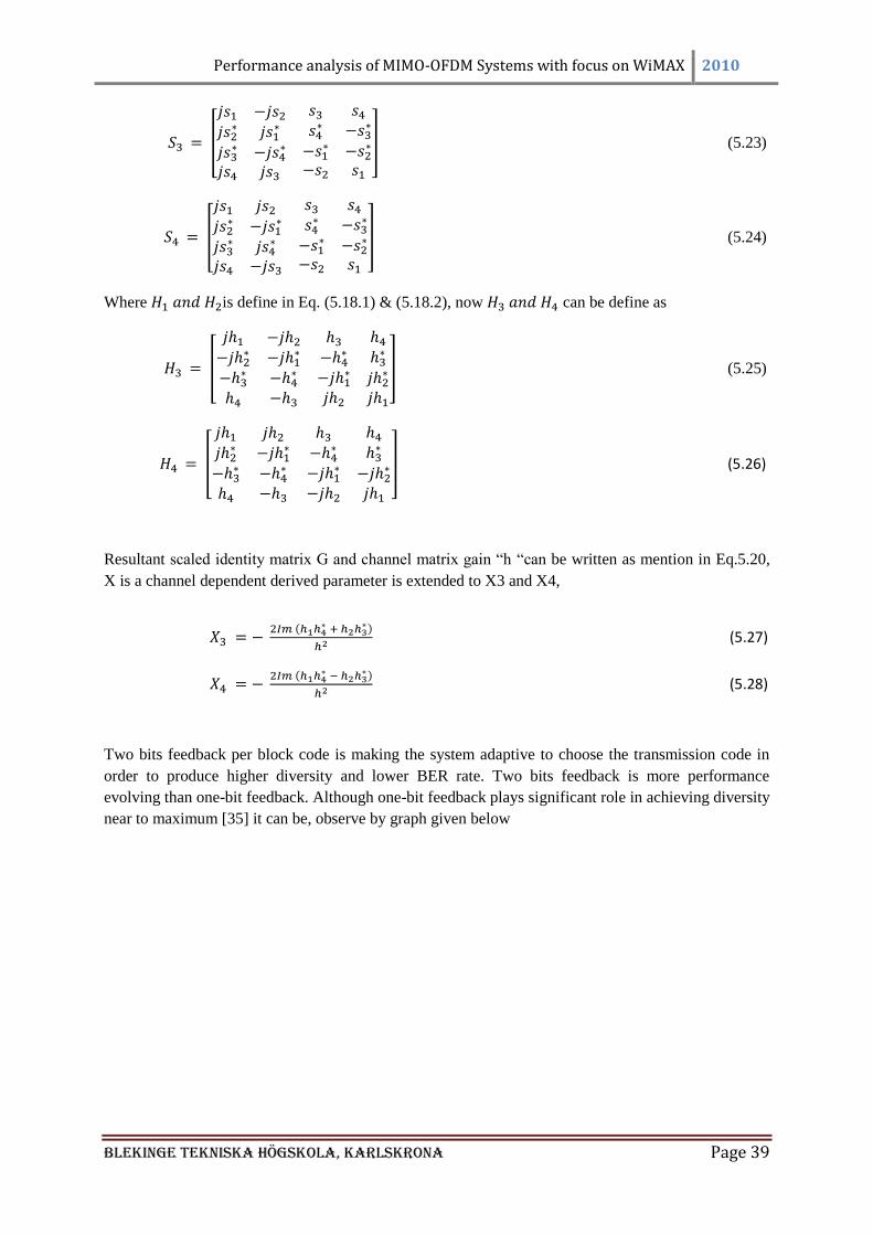
Performance analysis of MIMO-OFDM Systems with focus on WiMAX 2010
Blekinge Tekniska Högskola, KarlsKrona Page 39
(5.23)
(5.24)
Where is define in Eq. (5.18.1) & (5.18.2), now can be define as
(5.25)
(5.26)
Resultant scaled identity matrix G and channel matrix gain ―h ―can be written as mention in Eq.5.20,
X is a channel dependent derived parameter is extended to X3 and X4,
(5.27)
(5.28)
Two bits feedback per block code is making the system adaptive to choose the transmission code in
order to produce higher diversity and lower BER rate. Two bits feedback is more performance
evolving than one-bit feedback. Although one-bit feedback plays significant role in achieving diversity
near to maximum [35] it can be, observe by graph given below
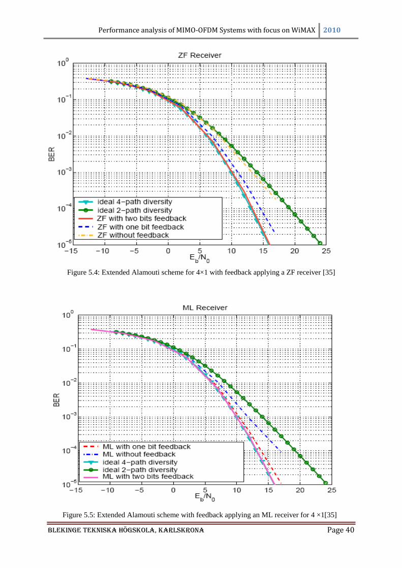
Performance analysis of MIMO-OFDM Systems with focus on WiMAX 2010
Blekinge Tekniska Högskola, KarlsKrona Page 40
Figure 5.4: Extended Alamouti scheme for 4×1 with feedback applying a ZF receiver [35]
Figure 5.5: Extended Alamouti scheme with feedback applying an ML receiver for 4 ×1[35]
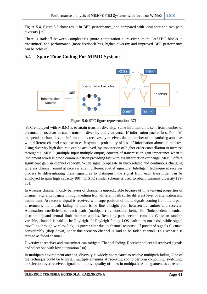
Performance analysis of MIMO-OFDM Systems with focus on WiMAX 2010
Blekinge Tekniska Högskola, KarlsKrona Page 41
Figure 5.4, figure 5.5-show result in BER performance, and compared with ideal four and two path
diversity [35].
There is tradeoff between complexities (more computation at receiver, more EASTBC blocks at
transmitter) and performance (more feedback bits, higher diversity and improved BER performance
can be achieve).
5.4 Space Time Coding For MIMO Systems
Figure 5.6: STC figure representation [37]
STC employed with MIMO is to attain transmit diversity. Same information is sent from number of
antennas to receiver to attain transmit diversity and vice versa. If information packet loss, from ‗n‘
independent channel same information is receives by receiver, due to number of transmitting antennas
with different channel response to each symbol, probability of loss of information almost eliminates.
Using diversity high data rate can be achieved, by implication of higher order constellation to increase
throughput. MIMO (multiple input multiple output) concept of transmission gain importance when it
implement wireless broad communication providing fast wireless information exchange. MIMO offers
significant gain in channel capacity. When signal propagate in uncorrelated and continuous changing
wireless channel, signal at receiver attain different spatial signature. Intelligent technique at receiver
process to differentiating these signatures to distinguish the signal from each transmitter can be
employed to gain high capacity [80]. In STC similar scheme is used to obtain transmit diversity [29-
30].
In wireless channel, mostly behavior of channel is unpredictable because of time varying properties of
channel. Signal propagate through medium from different path suffer different level of attenuation and
impairment. At receiver signal is received with superposition of multi signals coming from multi path
is termed s multi path fading. If there is no line of sight path between transmitter and receiver,
Attenuation coefficient to each path (multipath) is consider being iid (independent identical
distribution) and central limit theorem applies. Resulting path become complex Gaussian random
variable, channel is said to be Rayleigh. In Rayleigh fading LOS path does not exist, while signal
travelling through wireless link, its power alter due to channel response. If power of signals fluctuate
considerably (drop down) under this scenario channel is said to be faded channel. This scenario is
termed as faded channel.
Diversity at receiver and transmitter can mitigate Channel fading. Receiver collect all received signals
and select one with low attenuation [30].
In multipath environment antenna, diversity is widely appreciated to resolve multipath fading .One of
the technique could be to install multiple antennas at receiving end to perform combining, switching,
or selection over received signals to improve quality of links in multipath. Adding antennas at remote

Performance analysis of MIMO-OFDM Systems with focus on WiMAX 2010
Blekinge Tekniska Högskola, KarlsKrona Page 42
unit is not economical. It increases power size and make system expensive, better technique which is
in practice is to increase number of antenna at base station (cellular mobile networks). Which handle
huge number of user, so its cost, size and power issue could be bearable instead of providing all the
resources to remote receiver. In practice economical approaches transmit diversity is always
appreciated [30].
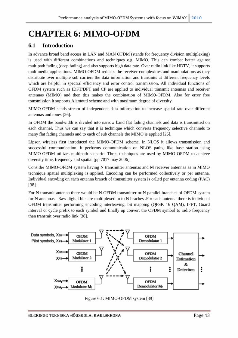
Performance analysis of MIMO-OFDM Systems with focus on WiMAX 2010
Blekinge Tekniska Högskola, KarlsKrona Page 43
CHAPTER 6: MIMO-OFDM
6.1 Introduction
In advance broad band access in LAN and MAN OFDM (stands for frequency division multiplexing)
is used with different combinations and techniques e.g. MIMO. This can combat better against
multipath fading (deep fading) and also supports high data rate. Over radio link like HDTV, it supports
multimedia applications. MIMO-OFDM reduces the receiver complexities and manipulations as they
distribute over multiple sub carriers the data information and transmits at different frequency levels
which are helpful in spectral efficiency and error control transmission. All individual functions of
OFDM system such as IDFT/DFT and CP are applied to individual transmit antennas and receiver
antennas (MIMO) and then this makes the combination of MIMO-OFDM. Also for error free
transmission it supports Alamouti scheme and with maximum degree of diversity.
MIMO-OFDM sends stream of independent data information to increase spatial rate over different
antennas and tones [26].
In OFDM the bandwidth is divided into narrow band flat fading channels and data is transmitted on
each channel. Thus we can say that it is technique which converts frequency selective channels to
many flat fading channels and to each of sub channels the MIMO is applied [25].
Lipson wireless first introduced the MIMO-OFDM scheme. In NLOS it allows transmission and
successful communication. It performs communication on NLOS paths, like base station using
MIMO-OFDM utilizes multipath scenario. Three techniques are used by MIMO-OFDM to achieve
diversity time, frequency and spatial [pp 7017 may 2006].
Consider MIMO-OFDM system having N transmitter antennas and M receiver antennas as in MIMO
technique spatial multiplexing is applied. Encoding can be performed collectively or per antenna.
Individual encoding on each antenna branch of transmitter system is called per antenna coding (PAC)
[38].
For N transmit antenna there would be N OFDM transmitter or N parallel branches of OFDM system
for N antennas. Raw digital bits are multiplexed in to N braches .For each antenna there is individual
OFDM transmitter performing encoding interleaving, bit mapping (QPSK 16 QAM), IFFT, Guard
interval or cycle prefix to each symbol and finally up convert the OFDM symbol to radio frequency
then transmit over radio link [38].
Figure 6.1: MIMO-OFDM system [39]
Performance analysis of MIMO-OFDM Systems with focus on WiMAX 2010
Blekinge Tekniska Högskola, KarlsKrona Page 44
The receiver should have information and estimation about channels for reliable wireless channel
transmission, the transmitter for this purpose transmits a training sequence periodically or with every
packet to receiver. So that according to channels variations the receiver could update. The training
sequence depends upon applications and requirements sent by transmitter to receiver. In order to keep
track of phase drift and amplitude variation the pilot symbols are used to insert it into OFDM
modulator.
At the receiver multiple antennas receive information and on the basis of training sequence it performs
estimation and correction in the preamble or performs forward error correction which depends upon
the encoding technique and equalization stages. In finding phase drift the Estimation or forward error
correction, frequency offset and symbol timings. Guard band is removed and information is presented
to IFFT. Then per OFDM sub channel MIMO detection is performed. Received signal of each sub
channel is sent to the MIMO detector to retrieve N signal transmitted on particular sub carrier. De
mapping, de inter leaving and decoding is done per transmitter symbol, resultant combine value is raw
digital data which was originally sent by transmitter and all these operations are performed over each
individual branch of receiver antennas .To the fourth generation communication system the MIMO
OFDM technology is door step [38].
With MIMO OFDM there are some certain limitations such as extra RF cost, antenna sizes and
complexities at receivers [40]. For cell mobiles because of mutual coupling and power limitation it is
still big issue to design and manufacture multiple antennas on cellular mobiles.
MIMO-OFDM is a technique which arises for mobile and wireless broad band access in combinations
of OFDM and MIMO. Due to its support to high speed wireless broad band access, low complexities
(in respect of equalization at receiver) and spectral efficiency and flexibilities, it is considered to be
prominent and promising candidate for further wireless technologies. Example are LTE, 4G, IEEE
802.16 (WiMAX), and IEEE 802.11n.
6.2 MIMO-OFDM and Space–Time Coding
New and tremendous potential has been introduced of increasing data rate and capacity with
experimental studies on technique of MIMO, with the introduction of OFDM with MIMO many lot
issues and reservation has been solved in regarding diversity and capacity of channel, great spectral
efficient environment can be attain by implanting MIMO with OFDM,[41-42]. In early research for
single carrier transmission flat fading channel consideration was considered, later on frequency
selective fading for single carrier is manipulated which produce same results in gain and ends with
complex equalization at receiver [41-42] for mobile communication.
On the other hand minimizing the complex equalization with great improvement and potential can be
achieved by considering MIMO-OFDM scheme which almost eliminate the complexity of
equalization [41].
Recent research and experiment by employing MIMO-OFDM scheme for QPSK modulation
considering four receiver and four transmitters (antennas) in first assumption and experiment with two
sixteen-state, two antenna STC ends up with improve result of 2 db enhancement over previous
research (code) at 5 Hz impairment[41], with further investigation of considering four antennas and 16
state code that result with lower the complexities and improvement f 12 dB gain, with 256 state code
that produce additional gain of 12dB and do excellent channel estimation with in 2dB with outage
capacity within 3 dB[41].
6.2.1 Experimental Evidence
The tremendous expected results are produced by experiment and calculation performs over the
MIMO using OFDM [41]. By considering M=2 transmitter and N=2 receiver considering Jakes
fading model and channel estimation from [43] and [44]and TU model assumed in [43], at frequency
bandwidth of 1.25 MHz provided to 256 sub carrier to achieve OFDM 1st and last 2 subcarriers are
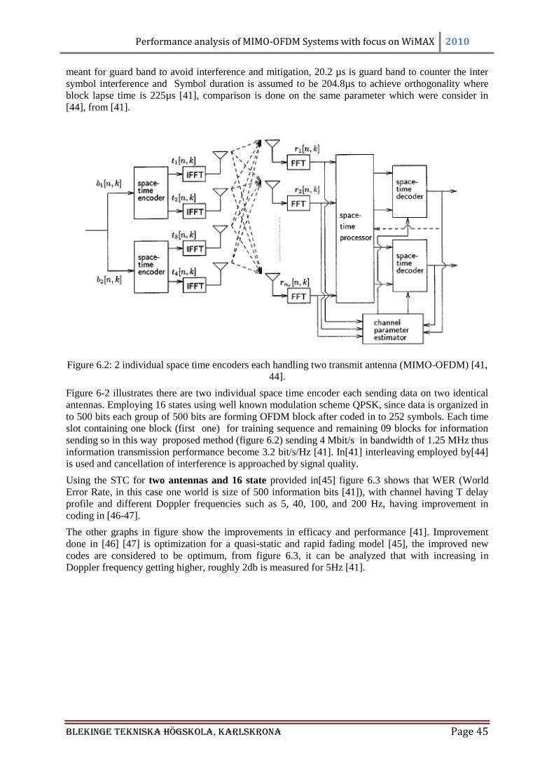
Performance analysis of MIMO-OFDM Systems with focus on WiMAX 2010
Blekinge Tekniska Högskola, KarlsKrona Page 45
meant for guard band to avoid interference and mitigation, 20.2 µs is guard band to counter the inter
symbol interference and Symbol duration is assumed to be 204.8µs to achieve orthogonality where
block lapse time is 225µs [41], comparison is done on the same parameter which were consider in
[44], from [41].
Figure 6.2: 2 individual space time encoders each handling two transmit antenna (MIMO-OFDM) [41,
44].
Figure 6-2 illustrates there are two individual space time encoder each sending data on two identical
antennas. Employing 16 states using well known modulation scheme QPSK, since data is organized in
to 500 bits each group of 500 bits are forming OFDM block after coded in to 252 symbols. Each time
slot containing one block (first one) for training sequence and remaining 09 blocks for information
sending so in this way proposed method (figure 6.2) sending 4 Mbit/s in bandwidth of 1.25 MHz thus
information transmission performance become 3.2 bit/s/Hz [41]. In[41] interleaving employed by[44]
is used and cancellation of interference is approached by signal quality.
Using the STC for two antennas and 16 state provided in[45] figure 6.3 shows that WER (World
Error Rate, in this case one world is size of 500 information bits [41]), with channel having T delay
profile and different Doppler frequencies such as 5, 40, 100, and 200 Hz, having improvement in
coding in [46-47].
The other graphs in figure show the improvements in efficacy and performance [41]. Improvement
done in [46] [47] is optimization for a quasi-static and rapid fading model [45], the improved new
codes are considered to be optimum, from figure 6.3, it can be analyzed that with increasing in
Doppler frequency getting higher, roughly 2db is measured for 5Hz [41].

Performance analysis of MIMO-OFDM Systems with focus on WiMAX 2010
Blekinge Tekniska Högskola, KarlsKrona Page 46
(a) 5 MHz Doppler (b) 40 MHz Doppler
(c)100 MHz Doppler (d) 200 MHz Doppler
Figure 6.3: MIMO system with M=N=4 using OFDM WER against SNR with different Doppler
frequencies for TU channel [41]
The result shows that the performance is better than the performance presented in figure 6-3; result
presented by figure 6.4 is given when if 4 antennas STC with 16 states and 256 state codes
implementing an adhoc approach.
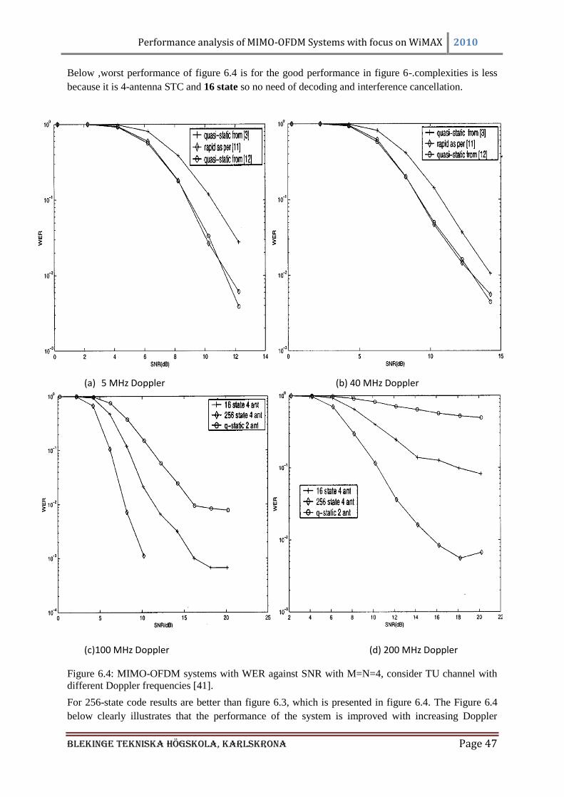
Performance analysis of MIMO-OFDM Systems with focus on WiMAX 2010
Blekinge Tekniska Högskola, KarlsKrona Page 47
Below ,worst performance of figure 6.4 is for the good performance in figure 6-.complexities is less
because it is 4-antenna STC and 16 state so no need of decoding and interference cancellation.
(a) 5 MHz Doppler (b) 40 MHz Doppler
(c)100 MHz Doppler (d) 200 MHz Doppler
Figure 6.4: MIMO-OFDM systems with WER against SNR with M=N=4, consider TU channel with
different Doppler frequencies [41].
For 256-state code results are better than figure 6.3, which is presented in figure 6.4. The Figure 6.4
below clearly illustrates that the performance of the system is improved with increasing Doppler

Performance analysis of MIMO-OFDM Systems with focus on WiMAX 2010
Blekinge Tekniska Högskola, KarlsKrona Page 48
frequency, (4 antenna STC 256 state) and also it attains 2 dB additional gain then previous assumption
(4 antenna STC with 16 states) [41].
From simulation results provided in figures (6.3, 6.4) by [41] represent that improvements in STC
performance can be achieved by doing further improvement.
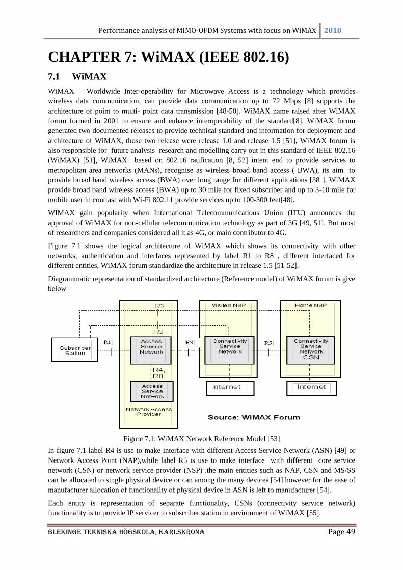
Performance analysis of MIMO-OFDM Systems with focus on WiMAX 2010
Blekinge Tekniska Högskola, KarlsKrona Page 49
CHAPTER 7: WiMAX (IEEE 802.16)
7.1 WiMAX
WiMAX – Worldwide Inter-operability for Microwave Access is a technology which provides
wireless data communication, can provide data communication up to 72 Mbps [8] supports the
architecture of point to multi- point data transmission [48-50]. WiMAX name raised after WiMAX
forum formed in 2001 to ensure and enhance interoperability of the standard[8], WiMAX forum
generated two documented releases to provide technical standard and information for deployment and
architecture of WiMAX, those two release were release 1.0 and release 1.5 [51], WiMAX forum is
also responsible for future analysis research and modelling carry out in this standard of IEEE 802.16
(WiMAX) [51], WiMAX based on 802.16 ratification [8, 52] intent end to provide services to
metropolitan area networks (MANs), recognise as wireless broad band access ( BWA), its aim to
provide broad band wireless access (BWA) over long range for different applications [38 ], WiMAX
provide broad band wireless access (BWA) up to 30 mile for fixed subscriber and up to 3-10 mile for
mobile user in contrast with Wi-Fi 802.11 provide services up to 100-300 feet[48].
WIMAX gain popularity when International Telecommunications Union (ITU) announces the
approval of WiMAX for non-cellular telecommunication technology as part of 3G [49, 51]. But most
of researchers and companies considered all it as 4G, or main contributor to 4G.
Figure 7.1 shows the logical architecture of WiMAX which shows its connectivity with other
networks, authentication and interfaces represented by label R1 to R8 , different interfaced for
different entities, WiMAX forum standardize the architecture in release 1.5 [51-52].
Diagrammatic representation of standardized architecture (Reference model) of WiMAX forum is give
below
Figure 7.1: WiMAX Network Reference Model [53]
In figure 7.1 label R4 is use to make interface with different Access Service Network (ASN) [49] or
Network Access Point (NAP),while label R5 is use to make interface with different core service
network (CSN) or network service provider (NSP) .the main entities such as NAP, CSN and MS/SS
can be allocated to single physical device or can among the many devices [54] however for the ease of
manufacturer allocation of functionality of physical device in ASN is left to manufacturer [54].
Each entity is representation of separate functionality, CSNs (connectivity service network)
functionality is to provide IP servicer to subscriber station in environment of WiMAX [55].
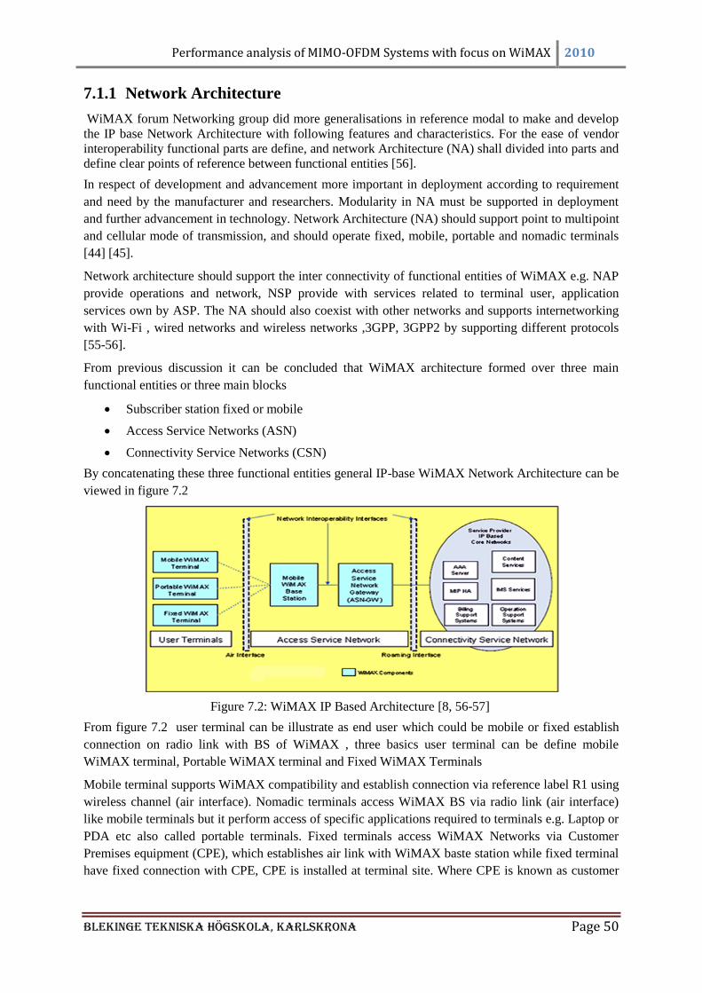
Performance analysis of MIMO-OFDM Systems with focus on WiMAX 2010
Blekinge Tekniska Högskola, KarlsKrona Page 50
7.1.1 Network Architecture
WiMAX forum Networking group did more generalisations in reference modal to make and develop
the IP base Network Architecture with following features and characteristics. For the ease of vendor
interoperability functional parts are define, and network Architecture (NA) shall divided into parts and
define clear points of reference between functional entities [56].
In respect of development and advancement more important in deployment according to requirement
and need by the manufacturer and researchers. Modularity in NA must be supported in deployment
and further advancement in technology. Network Architecture (NA) should support point to multipoint
and cellular mode of transmission, and should operate fixed, mobile, portable and nomadic terminals
[44] [45].
Network architecture should support the inter connectivity of functional entities of WiMAX e.g. NAP
provide operations and network, NSP provide with services related to terminal user, application
services own by ASP. The NA should also coexist with other networks and supports internetworking
with Wi-Fi , wired networks and wireless networks ,3GPP, 3GPP2 by supporting different protocols
[55-56].
From previous discussion it can be concluded that WiMAX architecture formed over three main
functional entities or three main blocks
Subscriber station fixed or mobile
Access Service Networks (ASN)
Connectivity Service Networks (CSN)
By concatenating these three functional entities general IP-base WiMAX Network Architecture can be
viewed in figure 7.2
Figure 7.2: WiMAX IP Based Architecture [8, 56-57]
From figure 7.2 user terminal can be illustrate as end user which could be mobile or fixed establish
connection on radio link with BS of WiMAX , three basics user terminal can be define mobile
WiMAX terminal, Portable WiMAX terminal and Fixed WiMAX Terminals
Mobile terminal supports WiMAX compatibility and establish connection via reference label R1 using
wireless channel (air interface). Nomadic terminals access WiMAX BS via radio link (air interface)
like mobile terminals but it perform access of specific applications required to terminals e.g. Laptop or
PDA etc also called portable terminals. Fixed terminals access WiMAX Networks via Customer
Premises equipment (CPE), which establishes air link with WiMAX baste station while fixed terminal
have fixed connection with CPE, CPE is installed at terminal site. Where CPE is known as customer
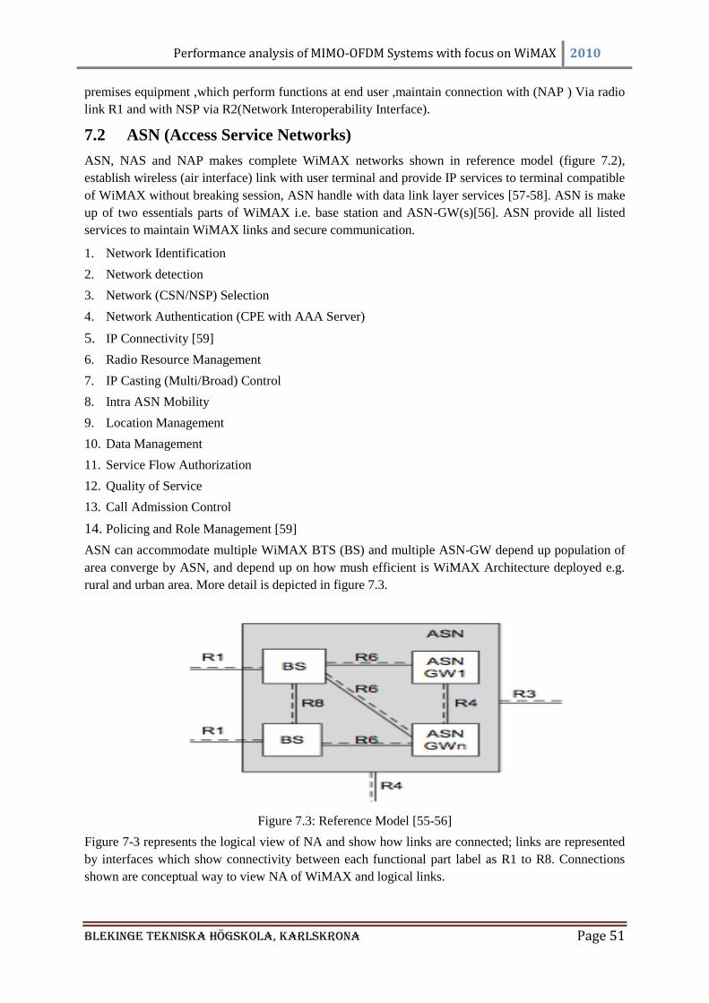
Performance analysis of MIMO-OFDM Systems with focus on WiMAX 2010
Blekinge Tekniska Högskola, KarlsKrona Page 51
premises equipment ,which perform functions at end user ,maintain connection with (NAP ) Via radio
link R1 and with NSP via R2(Network Interoperability Interface).
7.2 ASN (Access Service Networks)
ASN, NAS and NAP makes complete WiMAX networks shown in reference model (figure 7.2),
establish wireless (air interface) link with user terminal and provide IP services to terminal compatible
of WiMAX without breaking session, ASN handle with data link layer services [57-58]. ASN is make
up of two essentials parts of WiMAX i.e. base station and ASN-GW(s)[56]. ASN provide all listed
services to maintain WiMAX links and secure communication.
1. Network Identification
2. Network detection
3. Network (CSN/NSP) Selection
4. Network Authentication (CPE with AAA Server)
5. IP Connectivity [59]
6. Radio Resource Management
7. IP Casting (Multi/Broad) Control
8. Intra ASN Mobility
9. Location Management
10. Data Management
11. Service Flow Authorization
12. Quality of Service
13. Call Admission Control
14. Policing and Role Management [59]
ASN can accommodate multiple WiMAX BTS (BS) and multiple ASN-GW depend up population of
area converge by ASN, and depend up on how mush efficient is WiMAX Architecture deployed e.g.
rural and urban area. More detail is depicted in figure 7.3.
Figure 7.3: Reference Model [55-56]
Figure 7-3 represents the logical view of NA and show how links are connected; links are represented
by interfaces which show connectivity between each functional part label as R1 to R8. Connections
shown are conceptual way to view NA of WiMAX and logical links.
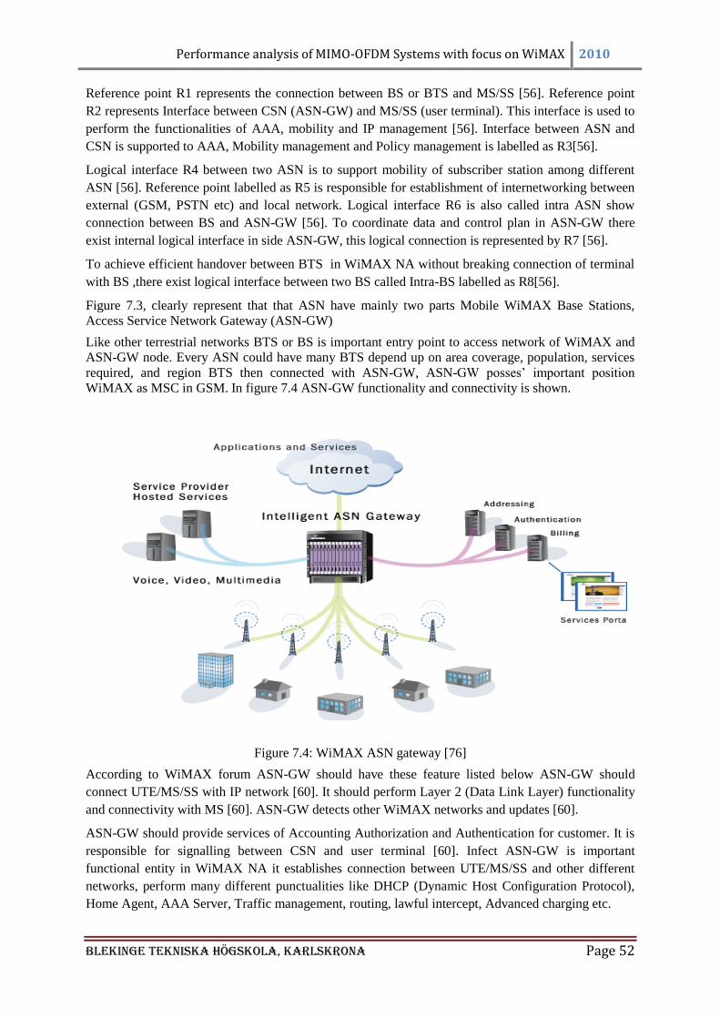
Performance analysis of MIMO-OFDM Systems with focus on WiMAX 2010
Blekinge Tekniska Högskola, KarlsKrona Page 52
Reference point R1 represents the connection between BS or BTS and MS/SS [56]. Reference point
R2 represents Interface between CSN (ASN-GW) and MS/SS (user terminal). This interface is used to
perform the functionalities of AAA, mobility and IP management [56]. Interface between ASN and
CSN is supported to AAA, Mobility management and Policy management is labelled as R3[56].
Logical interface R4 between two ASN is to support mobility of subscriber station among different
ASN [56]. Reference point labelled as R5 is responsible for establishment of internetworking between
external (GSM, PSTN etc) and local network. Logical interface R6 is also called intra ASN show
connection between BS and ASN-GW [56]. To coordinate data and control plan in ASN-GW there
exist internal logical interface in side ASN-GW, this logical connection is represented by R7 [56].
To achieve efficient handover between BTS in WiMAX NA without breaking connection of terminal
with BS ,there exist logical interface between two BS called Intra-BS labelled as R8[56].
Figure 7.3, clearly represent that that ASN have mainly two parts Mobile WiMAX Base Stations,
Access Service Network Gateway (ASN-GW)
Like other terrestrial networks BTS or BS is important entry point to access network of WiMAX and
ASN-GW node. Every ASN could have many BTS depend up on area coverage, population, services
required, and region BTS then connected with ASN-GW, ASN-GW posses‘ important position
WiMAX as MSC in GSM. In figure 7.4 ASN-GW functionality and connectivity is shown.
Figure 7.4: WiMAX ASN gateway [76]
According to WiMAX forum ASN-GW should have these feature listed below ASN-GW should
connect UTE/MS/SS with IP network [60]. It should perform Layer 2 (Data Link Layer) functionality
and connectivity with MS [60]. ASN-GW detects other WiMAX networks and updates [60].
ASN-GW should provide services of Accounting Authorization and Authentication for customer. It is
responsible for signalling between CSN and user terminal [60]. Infect ASN-GW is important
functional entity in WiMAX NA it establishes connection between UTE/MS/SS and other different
networks, perform many different punctualities like DHCP (Dynamic Host Configuration Protocol),
Home Agent, AAA Server, Traffic management, routing, lawful intercept, Advanced charging etc.
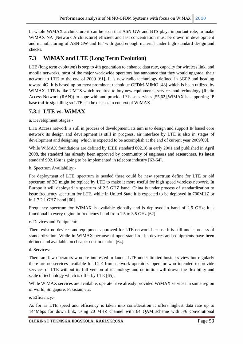
Performance analysis of MIMO-OFDM Systems with focus on WiMAX 2010
Blekinge Tekniska Högskola, KarlsKrona Page 53
In whole WiMAX architecture it can be seen that ASN-GW and BTS plays important role, to make
WiMAX NA (Network Architecture) efficient and fast concentration must be drawn in development
and manufacturing of ASN-GW and BT with good enough material under high standard design and
checks.
7.3 WiMAX and LTE (Long Term Evolution)
LTE (long term evolution) is step to 4th generation to enhance data rate, capacity for wireless link, and
mobile networks, most of the major worldwide operators has announce that they would upgrade their
network to LTE to the end of 2009 [61]. It is new radio technology defined in 3GPP and heading
toward 4G. It is based up on most prominent technique OFDM-MIMO [48] which is been utilized by
WiMAX. LTE is like UMTS which required to buy new equipments, services and technology (Radio
Access Network (RAN)) to cope with and provide IP base services [55,62],WiMAX is supporting IP
base traffic signalling so LTE can be discuss in context of WiMAX .
7.3.1 LTE vs. WiMAX
a. Development Stages:-
LTE Access network is still in process of development. Its aim is to design and support IP based core
network its design and development is still in progress, air interface by LTE is also in stages of
development and designing which is expected to be accomplish at the end of current year 2009[60].
While WiMAX foundations are defined by IEEE standard 802.16 in early 2001 and published in April
2008, the standard has already been approved by community of engineers and researchers. Its latest
standard 902.16m is going to be implemented in telecom industry [63-64].
b. Spectrum Availability:-
For deployment of LTE, spectrum is needed there could be new spectrum define for LTE or old
spectrum of 2G might be replace by LTE to make it more useful for high speed wireless network. In
Europe it will deployed in spectrum of 2.5 GHZ band. China is under process of standardization to
issue frequency spectrum for LTE, while in United State it is expected to be deployed in 700MHZ or
in 1.7.2.1 GHZ band [60].
Frequency spectrum for WiMAX is available globally and is deployed in band of 2.5 GHz; it is
functional in every region in frequency band from 1.5 to 3.5 GHz [62].
c. Devices and Equipment:-
There exist no devices and equipment approved for LTE network because it is still under process of
standardization. While in WiMAX because of open standard, its devices and equipments have been
defined and available on cheaper cost in market [64].
d. Services:-
There are few operators who are interested to launch LTE under limited business view but regularly
there are no services available for LTE from network operators, operator who intended to provide
services of LTE without its full version of technology and definition will drown the flexibility and
scale of technology which is offer by LTE [65].
While WiMAX services are available, operate have already provided WiMAX services in some region
of world, Singapore, Pakistan, etc.
e. Efficiency:-
As for as LTE speed and efficiency is taken into consideration it offers highest data rate up to
144Mbps for down link, using 20 MHZ channel with 64 QAM scheme with 5/6 convolutional
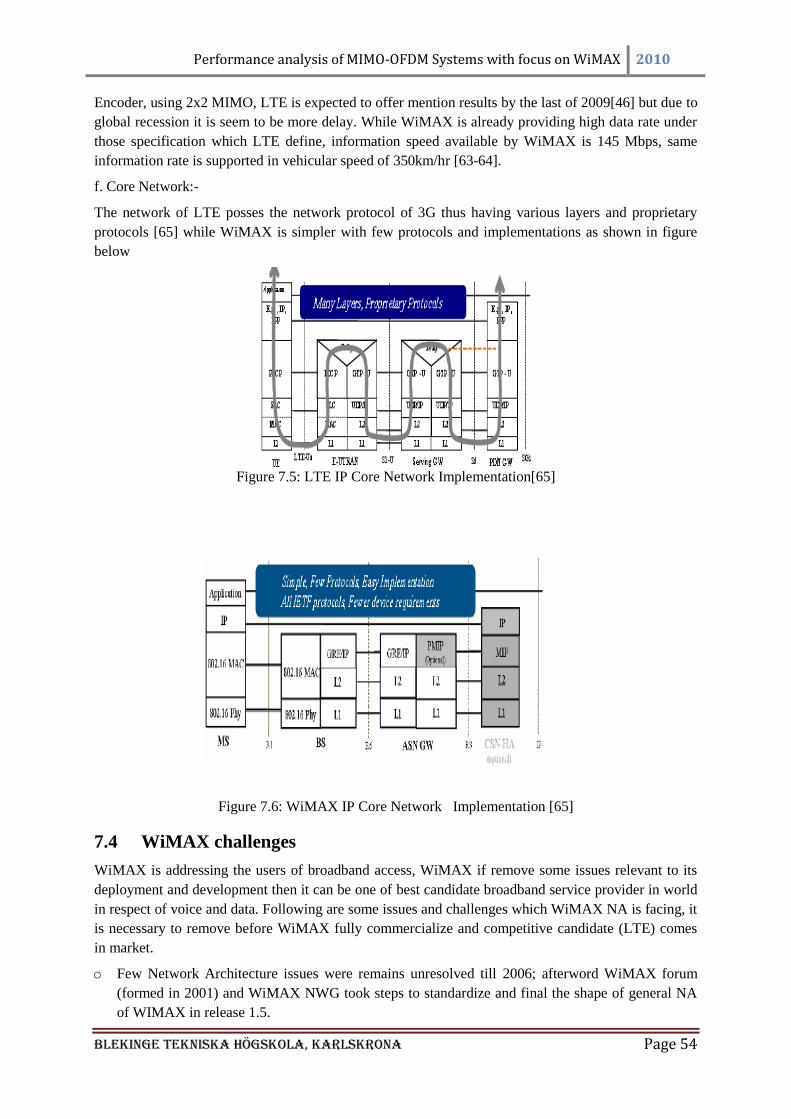
Performance analysis of MIMO-OFDM Systems with focus on WiMAX 2010
Blekinge Tekniska Högskola, KarlsKrona Page 54
Encoder, using 2x2 MIMO, LTE is expected to offer mention results by the last of 2009[46] but due to
global recession it is seem to be more delay. While WiMAX is already providing high data rate under
those specification which LTE define, information speed available by WiMAX is 145 Mbps, same
information rate is supported in vehicular speed of 350km/hr [63-64].
f. Core Network:-
The network of LTE posses the network protocol of 3G thus having various layers and proprietary
protocols [65] while WiMAX is simpler with few protocols and implementations as shown in figure
below
Figure 7.5: LTE IP Core Network Implementation[65]
Figure 7.6: WiMAX IP Core Network Implementation [65]
7.4 WiMAX challenges
WiMAX is addressing the users of broadband access, WiMAX if remove some issues relevant to its
deployment and development then it can be one of best candidate broadband service provider in world
in respect of voice and data. Following are some issues and challenges which WiMAX NA is facing, it
is necessary to remove before WiMAX fully commercialize and competitive candidate (LTE) comes
in market.
o Few Network Architecture issues were remains unresolved till 2006; afterword WiMAX forum
(formed in 2001) and WiMAX NWG took steps to standardize and final the shape of general NA
of WIMAX in release 1.5.
Performance analysis of MIMO-OFDM Systems with focus on WiMAX 2010
Blekinge Tekniska Högskola, KarlsKrona Page 55
o In many developed countries like China and USA, network operators are interested in fixed mode
of transmission for WiMAX, and not taking cellular transmission mode for WiMAX in
consideration [64, 66].
o There also exists issue of backward compatibility, WiMAX mobile mode of transmission is not
back word compatible with fixed terrestrial networks [66].
o Consideration of RF transmission for WiMAX in 2006 shows that if smart antenna is deployed at
cell site at frequency band of 3.5GHz, to void the effect of RF Propagation, but smart antenna on
the other hand not actively responsive to mobile user and also expensive, later on MIMO with
OFDM has resolved many issues, but still cost of development and deployment issue persists [64,
66].
o Although WiMAX is define by IEEE standard, providing high data rates but still it will take time
to develop in rank in market [66].
o Main issue regarding WiMAX radio ASN is, its deployment cost is higher than its predecessor Wi-
Fi [50], deployment cost for WiMAX is not taken in to consideration carefully.
If WiMAX NA fails to remove its demerit, in end of 2009 LTE standardization is expected to be
completed, which will reuse its network architecture and IP core networks and 85 % of the research
and technology of WiMAX would be adopted by LTE [64].
Performance analysis of MIMO-OFDM Systems with focus on WiMAX 2010
Blekinge Tekniska Högskola, KarlsKrona Page 56
CHAPTER 8: Design and Simulation Results Matlab is strong mathematical tool which provide help to engineers to solve, model, simulate the
problems and find solutions assuming environment in to mathematical equations. It is standard
engineering tool as perform many different tasks using different tool box relevant to different
particular cases e.g. Control systems, signal processing, image processing, communication systems,
and support complex matrix manipulation, simulink etc
In different fields like research and universities it provides platform for learning and comparison of
theatrical hypothesis and simulated values. It even provides support to nonlinear system calculations
and result [67].
8.1 Simulation and procedure
In this report Matlab7.0 is used to simulate and models the different problems for analysis and results.
Different features of symbolic toolbox is used in simulation for Alamouti scheme (Space Time Block
Code) which are not supported by older version of Matlab in order to simulate the provided code
Matlab 7.0 is appropriate software package to get the required results.
8.2 Alamouti scheme using Matlab symbolic toolbox
Symbolic Tool Box
Matlab consist of different tool boxes, symbolic tool box is one of them to allow symbolic
mathematical computation to track and analyze mathematical complex equations. It is helpful in
command and control of mathematical manipulation, it can use simply by writing command in Matlab
environment.
Alamouti coding technique is using computation of complex numbers; to understand the mathematical
operations perform by Alamouti technique the simple way is to manipulate it in symbolic tool box.
In this report 2 × 1 MIMO antenna system is manipulated using symbolic tool box in order to
understand the mathematical operation, and to verify and rectify the mathematical model of Alamouti
scheme.
8.2.1 Procedure and simulation of 2×1 System
The procedure of the 2x1 system is that the Alamouti transmitted symbols are and on the first
symbol interval and in the next symbol interval the conjugates of the transmitted symbol are
transmitted which is denoted by and
respectively. And the channel is assume to be static
between the two time interval, in mathematical representation it can be shown as
Channel, (8.1)
Whereas the symbol matrix can be written as
(8.2)
Where the is the symbol matrix and and are the two symbols which is transmitted. While at the
receiver end we get the matrix with the effect of channel parameters called and i.e.
The received matrix is the multiplication of channel matrix and symbol matrix that is
(8.3)
Performance analysis of MIMO-OFDM Systems with focus on WiMAX 2010
Blekinge Tekniska Högskola, KarlsKrona Page 57
We get the matrix,
Than the received matrix is multiply with the hermitian transpose matrix of symbol matrix, so the
results in the following equation given below
(8.4)
So from Eq. 8.4 we can get,
(8.5)
Where in Eq. 8.5, represents the received matrix and representing the effective matrix after
multiplying the 2nd
element of the received matrix with the negative complex conjugate, so will get the
required result i.e.
(8.6)
(8.7)
Where Eq. 8.7, is first received symbol and its conjugate of the symbol. Where the matrix
can be written as,
(8.8)
Now the two symbols which we have transmitted before can also be retrieve by
multiplying inverse of effective channel matrix with received matrix, i.e. given in Eq. 8.9.
(8.9)
8.2.2 Matlab symbolic tool box programming for 2 × 1 system
The implementation of Alamouti scheme using Symbolic tool box for two transmitters and one
receiver, Noise is assume to be zero.
syms h1 h2 s1 s2 % declare symbol
S = [[s1 ;s2],[s2';-s1']] % S matrix
h = [h1,h2] % h matrix
H = [[h1,h2];[h2',-h1']] % effective H matix
R = h*S % recieve matrix after channel response
Q = [R(1);-R(2)'] % conjugate of revice matix
SS = simple(H'*Q) % to find S
SSS = collect (SS, s1)
SSSS = collect (SSS, s2)
Performance analysis of MIMO-OFDM Systems with focus on WiMAX 2010
Blekinge Tekniska Högskola, KarlsKrona Page 58
hh = h*h'
SSSS/he
Results after executing the above code
S = [ s1, conj(s2)]
[ s2, -conj(s1)]
h = [ h1, h2]
H = [ h1, h2]
[ conj(h2), -conj(h1)]
R = [ s1*h1+s2*h2, conj(s2)*h1-conj(s1)*h2]
Q = [ s1*h1+s2*h2]
[ -conj(conj(s2)*h1-conj(s1)*h2)]
SS = [ h1*conj(h1)*s1+h2*s1*conj(h2)]
[ conj(h2)*s2*h2+h1*s2*conj(h1)]
SSS = [ (h1*conj(h1)+h2*conj(h2))*s1]
[ conj(h2)*s2*h2+h1*s2*conj(h1)]
SSSS = [ (h1*conj(h1)+h2*conj(h2))*s1]
[ (h1*conj(h1)+h2*conj(h2))*s2]
hh = h1*conj(h1)+h2*conj(h2)
ans = [ s1]
[ s2]
Finally computation at receiver generates back the symbol s1 and s2 which were transmitted from
transmitter.
8.3 Simulation result
o Finally simulation performed on MIMO system by using Alamouti scheme by considering
different antenna arrangement i.e. is 2×1 MIMO system, 2×2 MIMO system and 2×3 MIMO
system [68]. The basic concept of programming is same as mention in the above paragraphs; the
mathematical values are assumed in order to get BER performance.
o Long time taken to produce simulated result is 250.9497 seconds in Matlab version. The number
of symbols is taken as 10^6, larger symbols are chosen to visualize result in maximum swing.
o Eb/No ratio range is defined, it is taken from 0 to 15 if taken larger, and it takes more time to
produce result.
o Random data is generated for 15 times (length of Eb/No), it is considered as x-axis for BER graph
.on y-axis BER is taken from range of 10^-5 to 0.9.
o Number of receiver are taken 1, 2, 3 with two transmitter, three different BER graphs are define
for receivers respectively.
o It can be seen in figures that simulated result is identical to theoretical and expected result.
To evaluate the performance of different MIMO transmission schemes for different number of receiver
antennas and transmitter antennas simulations were performed. All scenarios involved simulation of
the wireless MIMO channel and a sequence of data symbols was transmitted by using different MIMO
systems. The performance metric used is the Bit Error Rate.
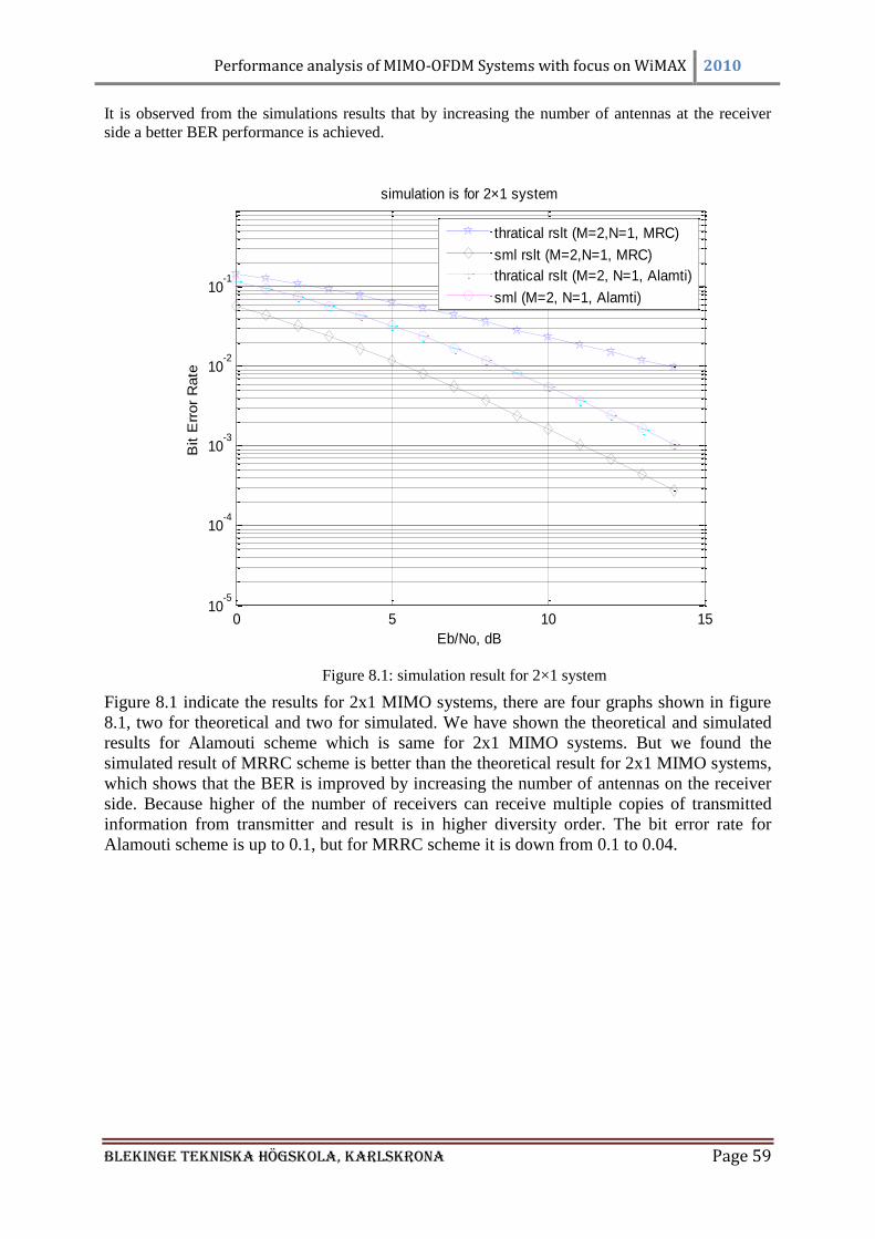
Performance analysis of MIMO-OFDM Systems with focus on WiMAX 2010
Blekinge Tekniska Högskola, KarlsKrona Page 59
It is observed from the simulations results that by increasing the number of antennas at the receiver
side a better BER performance is achieved.
Figure 8.1: simulation result for 2×1 system
Figure 8.1 indicate the results for 2x1 MIMO systems, there are four graphs shown in figure
8.1, two for theoretical and two for simulated. We have shown the theoretical and simulated
results for Alamouti scheme which is same for 2x1 MIMO systems. But we found the
simulated result of MRRC scheme is better than the theoretical result for 2x1 MIMO systems,
which shows that the BER is improved by increasing the number of antennas on the receiver
side. Because higher of the number of receivers can receive multiple copies of transmitted
information from transmitter and result is in higher diversity order. The bit error rate for
Alamouti scheme is up to 0.1, but for MRRC scheme it is down from 0.1 to 0.04.
0 5 10 1510
-5
10-4
10-3
10-2
10-1
Eb/No, dB
Bit E
rror
Rate
simulation is for 2×1 system
thratical rslt (M=2,N=1, MRC)
sml rslt (M=2,N=1, MRC)
thratical rslt (M=2, N=1, Alamti)
sml (M=2, N=1, Alamti)
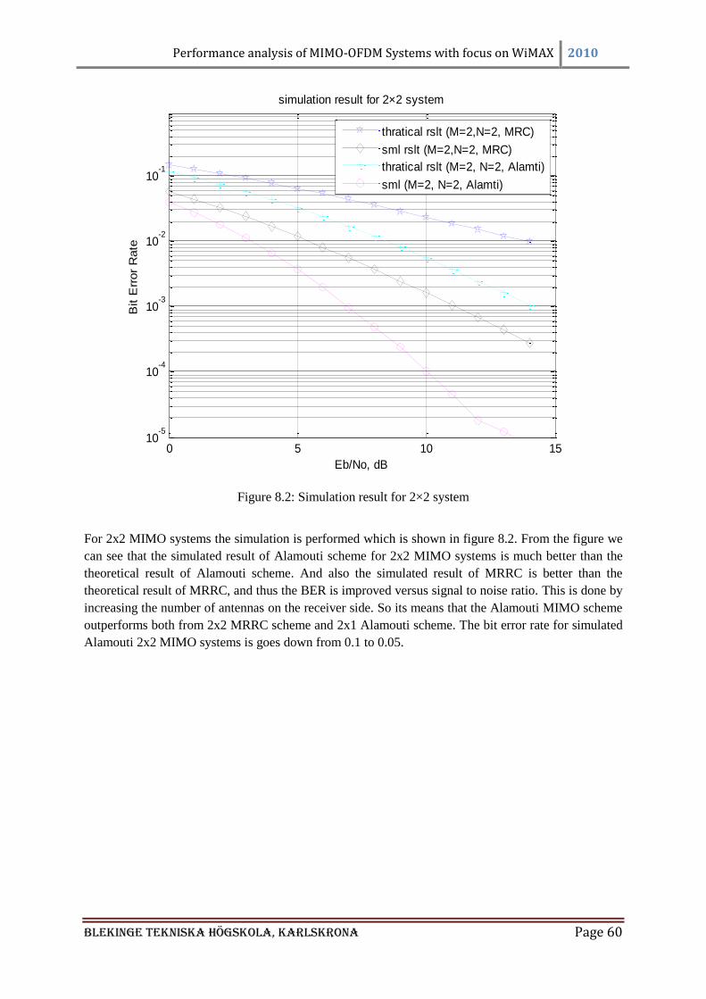
Performance analysis of MIMO-OFDM Systems with focus on WiMAX 2010
Blekinge Tekniska Högskola, KarlsKrona Page 60
Figure 8.2: Simulation result for 2×2 system
For 2x2 MIMO systems the simulation is performed which is shown in figure 8.2. From the figure we
can see that the simulated result of Alamouti scheme for 2x2 MIMO systems is much better than the
theoretical result of Alamouti scheme. And also the simulated result of MRRC is better than the
theoretical result of MRRC, and thus the BER is improved versus signal to noise ratio. This is done by
increasing the number of antennas on the receiver side. So its means that the Alamouti MIMO scheme
outperforms both from 2x2 MRRC scheme and 2x1 Alamouti scheme. The bit error rate for simulated
Alamouti 2x2 MIMO systems is goes down from 0.1 to 0.05.
0 5 10 1510
-5
10-4
10-3
10-2
10-1
Eb/No, dB
Bit E
rror
Rate
simulation result for 2×2 system
thratical rslt (M=2,N=2, MRC)
sml rslt (M=2,N=2, MRC)
thratical rslt (M=2, N=2, Alamti)
sml (M=2, N=2, Alamti)
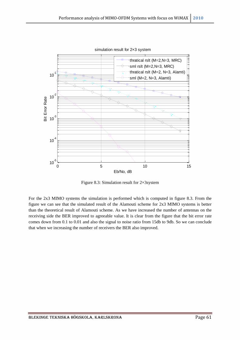
Performance analysis of MIMO-OFDM Systems with focus on WiMAX 2010
Blekinge Tekniska Högskola, KarlsKrona Page 61
Figure 8.3: Simulation result for 2×3system
For the 2x3 MIMO systems the simulation is performed which is computed in figure 8.3. From the
figure we can see that the simulated result of the Alamouti scheme for 2x3 MIMO systems is better
than the theoretical result of Alamouti scheme. As we have increased the number of antennas on the
receiving side the BER improved to agreeable value. It is clear from the figure that the bit error rate
comes down from 0.1 to 0.01 and also the signal to noise ratio from 15db to 9db. So we can conclude
that when we increasing the number of receivers the BER also improved.
0 5 10 1510
-5
10-4
10-3
10-2
10-1
Eb/No, dB
Bit E
rror
Rate
simulation result for 2×3 system
thratical rslt (M=2,N=3, MRC)
sml rslt (M=2,N=3, MRC)
thratical rslt (M=2, N=3, Alamti)
sml (M=2, N=3, Alamti)
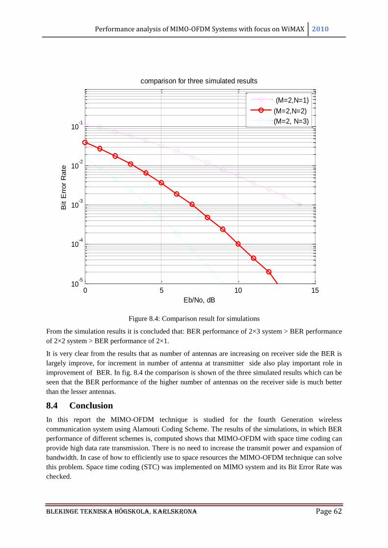
Performance analysis of MIMO-OFDM Systems with focus on WiMAX 2010
Blekinge Tekniska Högskola, KarlsKrona Page 62
Figure 8.4: Comparison result for simulations
From the simulation results it is concluded that: BER performance of 2×3 system > BER performance
of 2×2 system > BER performance of 2×1.
It is very clear from the results that as number of antennas are increasing on receiver side the BER is
largely improve, for increment in number of antenna at transmitter side also play important role in
improvement of BER. In fig. 8.4 the comparison is shown of the three simulated results which can be
seen that the BER performance of the higher number of antennas on the receiver side is much better
than the lesser antennas.
8.4 Conclusion
In this report the MIMO-OFDM technique is studied for the fourth Generation wireless
communication system using Alamouti Coding Scheme. The results of the simulations, in which BER
performance of different schemes is, computed shows that MIMO-OFDM with space time coding can
provide high data rate transmission. There is no need to increase the transmit power and expansion of
bandwidth. In case of how to efficiently use to space resources the MIMO-OFDM technique can solve
this problem. Space time coding (STC) was implemented on MIMO system and its Bit Error Rate was
checked.
0 5 10 1510
-5
10-4
10-3
10-2
10-1
Eb/No, dB
Bit E
rror
Rate
comparison for three simulated results
(M=2,N=1)
(M=2,N=2)
(M=2, N=3)
Performance analysis of MIMO-OFDM Systems with focus on WiMAX 2010
Blekinge Tekniska Högskola, KarlsKrona Page 63
For the simulation purpose MATLAB version 7.0 was used. MIMO system uses OFDM. 1st attempt is
a 2×1 MIMO system with STC implemented in symbolic tool box, and then it is raised to 2× (N
receiver) systems. In symbolic representation noise in channel is considered to be zero for
understanding and verification of mathematical operation in simple. BER has been improved to a good
agreeable value as proved by the results from the simulation.
From the simulation results when the number of antennas on the receiver side increases the Bit Error
Rate reduces. For our studies we simulated the 2x1 MIMO system and the Bit Error Rate as a function
of SNR was computed, fig. 8.1 shows that the theoretical result of the Alamouti scheme is almost
identical to the simulated result.
In the second simulation result which is shown in fig. 8.2, when the number of antennas increased on
the receiver side the BER is reduced, this is shown in the figure by plotting the 2x1 Alamouti scheme
and the simulated 2x2 Alamouti scheme together. In the same way we studied the 2x3 system as well.
From all the simulation results of the Alamouti scheme which are compared in fig. 8.4, we conclude
that the BER performance of the 2x3 system is much better than the 2x2 and 2x1 systems. So it means
when the number of antennas increased on the receiver side the BER improves.
Future work
Future work can be done on this system, by combining OFDM and STBC for MIMO, OFDM
demodulator and channel effects with different noise models can be simulated. There could be many
experiments performed considering this approach in different environment indoors and out door, to
make system adaptive and develop feedback approach.
Performance analysis of MIMO-OFDM Systems with focus on WiMAX 2010
Blekinge Tekniska Högskola, KarlsKrona Page 64
REFERENCES
[1] IEEE. Available: http://en.wikipedia.org/wiki/Ieee [2] IEEE Standards Online Collections. Available:
http://www.ieee.org/web/publications/subscriptions/prod/standards_overview.html [3] 802.11 Available: http://www.webopedia.com/TERM/8/802_11.html [4] 802.1x Available: http://www.webopedia.com/TERM/8/802_1x.html [5] 802.16 Available: http://www.webopedia.com/TERM/8/802_16.html [6] IEEE Standard 802.16: A Technical Overview of the Wireless MAN™
Air Interface for Broadband Wireless Access. Available:
http://wirelessman.org/docs/02/C80216- 02_05.pdf [7] WiMAX. Available: http://ocw.kfupm.edu.sa/user062/COE34202/WiMAX%20-
%20Wireless%20to%20the%20MAX.pdf [8] Wikipedia. Available: http://en.wikipedia.org/wiki/WiMAX [9] R. Olexa. implementing 802.11,802.16,and 802.20 wireless network ,planning troubleshooting
and operations Available:
http://books.google.co.uk/books?id=qytvAz_VYKQC&dq=Ron+Olexa,+Implementing+802.1
1,+802.16+and+802.20+Wireless+Networks,&printsec=frontcover&source=bn&hl=en&ei=H
Up9SvCgM926jAfSsvjwAQ&sa=X&oi=book_result&ct=result&resnum=4#v=onepage&q=&
f=true(pp xi). [10] Coherence time. Available: http://en.wikipedia.org/wiki/Coherence_time. [11] E. a. C. E. Zhifeng Chen, University of Florida. Performance Analysis of Channel Estimation
and Adaptive Equalization in Slow Fading Channel. Available:
http://www.wu.ece.ufl.edu/projects/channelEstimation/documents/Final%20Report.pdf [12] Fading. Available: http://en.wikipedia.org/wiki/Slow_fading [13] H. Hashemi, "The Indoor Radio Propagation Channel," Proceedings of IEEE, vol. 81, pp. 943-
968, July 1993. [14] C. S. WAN, "Mobile radio propagation " UNIVERSITY OF BRADFORD27th of April 2009
2007
[15] D. Matiæ. (1998, OFDM as a possible modulation technique for multimedia applications in
the range of mm waves. Introduction to OFDM (10/30/98/TUD-TVS). Available:
http://privatewww.essex.ac.uk/~mpthak/introOFDM.pdf [16] R. W. Chang, "Synthesis of Band-Limited Orthogonal Signals for Multichannel Data
Transmission," Bell Syst. Tech. J, vol. 45, pp. 1775-1796, Dec. 1966. [17] B. R. Salzberg. Performance of an efficient parallel data transmission system. IEEE Trans
Comun. COM-15, 805-813. [18] K. Pietikäinen. Orthogonal Frequency Division Multiplexing. Available:
http://www.comlab.hut.fi/opetus/333/2004_2005_slides/ofdm_text.pdf [19] R. V. a. R. P. Nee. OFDM for Wireless Communication (2000). [20] H. Dave, "investigation of various modulation techniques over OFDM and design of CODED
OFDM System," university of Bradford 2007-2008
[21] Rayleigh fading. Available: http://en.wikipedia.org/wiki/Rayleigh_fading [22] Rician fading. Available: http://en.wikipedia.org/wiki/Rician_fading [23] S. A. J. Andrea Goldsmith, Nihar Jindal, and Sriram Vishwanath. (2002, November 8, 2002).
Fundamental Capacity of MIMO Channels. CA 94305, 2/36. Available:
http://wsl.stanford.edu/~ee359/mimo_tutorial.pdf [24] T.-S. Lee. MIMO Techniques for Wireless Communications. Available:
http://www.comlab.hut.fi/opetus/333/2004_2005_slides/Space_Time_Codes_for_MIMO.pdf
[25] RESEARCH ON MULTI-ANTENNA RECEIVERS AND MIMO SYSTEMS IN DIGITAL MOBILE RADIO. Available:
http://www.signal.uu.se/Research/rdiversity.html [26] S´ebastien de la Kethulle — September 27. An Overview of MIMO Systems in Wireless
Communications. Available: http://www.iet.ntnu.no/projects/beats/Documents/mimo.pdf [27] K. W. F. Daniel W. Bliss, and Amanda M. Chan, "MIMO Wireless
Performance analysis of MIMO-OFDM Systems with focus on WiMAX 2010
Blekinge Tekniska Högskola, KarlsKrona Page 65
Communication," LINCOLN LABORATORY JOURNAL, vol. 15,, pp. 97-98, 2005. [28] F. Gregorio. Space Time code for MIMO Systems. Available:
http://www.comlab.hut.fi/opetus/333/2004_2005_slides/Space_Time_Codes_for_MIMO.pdf [29] B. V. a. J. Yuan, "Space-Time Coding," John Wiley 2003.
[30] H. Fernando H. Gregorio. SPACE TIME CODING FOR MIMO SYSTEMS. Available:
http://www.comlab.hut.fi/opetus/333/2004_2005_slides/space_time_codes_text.pdf [31] V. J. Tarokh, H.; Calderbank, A.R. (,March 1999, Space-time block coding for wireless
communications. Vol. 17 (IEEE JSAC). [32] M. R. Biljana Badic, Hans Weinrichter, "ADAPTIVE CHANNEL MATCHED EXTENDED
ALAMOUTI SPACE-TIME CODE EXPLOITING PARTIAL FEEDBACK," International
conference on cellular and intelligent communication (CIC),seoul,korea;, p. 350., 2003. [33] M. L. A. Narula, M.Trott and G. Wornell, "Efficient use of side information in multiple
antenna data transmission over fading channels,," IEEE J. Sel. Ar. Comm, vol. 16, pp. 1423-
1436, , Oct. 1998. [34] A. S. a. B. A. S. Bhashyam, "Feedback gain in multiple antenna systems," IEEE Trans,
Comm, vol. 48, , pp. 83-94, May 2002. [35] S. M. Alamouti, "A Simple Diversity Technique for Wireless Communications," vol. 16, pp.
1451-1458, Oct. 1998.
[36] M. R. C.F.Mecklenbr¨auker, "On Extended Alamouti Schemes for Space-Time Coding,,"
WPMC’02, Honolulu, Oct. 2002. [37] T.-S. Lee, Department of Communication Engineering National Chiao Tung University.
[38] A. v. Z. a. T. C. W. Schenk, "Implementation of MIMO OFDM –based Wireless Lan System,"
IEEE transmission on signal processing, vol. 52, februray 2004. [39] MIMO-OFDM Design using LabVIEW. Available:
http://images.google.co.uk/imgres?imgurl=http://users.ece.utexas.edu/~jandrews/molabview_f
iles/mimoofdm.gif&imgrefurl=http://users.ece.utexas.edu/~jandrews/molabview.html&usg=_
_1f925tFKXs3IlpdTnS0JqmTaaDA=&h=200&w=550&sz=19&hl=en&start=2&tbnid=qgb4cl
NlH6IfsM:&tbnh=48&tbnw=133&prev=/images%3Fq%3DMIMO-
OFDM%26gbv%3D2%26hl%3Den [40] J. ZE, "MIMO_OFDM system for WiMAX ", School of Engineering ,Design and
Technology ,University Of Bradford 5th work shop proceedings 17 may 2006.
[41] Y. G. L. Rick S. Blum, Jack H. Winters, and Qing Yan, "Improved Space–Time Coding for
MIMO-OFDM Wireless Communications ". IEEE TRANSACTIONS ON
COMMUNICATIONS, vol. VOL. 49,, p. PP 1873, , NOVEMBER 2001. [42] J. Foschini, "Layered space–time architecture for wireless communication in a fading
environment when using multi-element antennas," Bell Labs Tech. J, vol. vol. 1, , pp., pp. 41–
59, , 1996. [43] N. S. Y. G. Li, and S. Ariyavisitakul, "Channel estimation for OFDM systems with
transmitter diversity in mobile wireless channels," IEEE J. Select. Areas Commun., , vol.
vol. 17, , pp. pp. 461–471, , Mar. 1999. [44] J. H. W. Y. G. Li, and N. R. Sollenberger, "Signal detection for
MIMO-OFDM wireless communications,," IEEE Int. Conf. Commun, June 2001. [45] N. S. V. Tarokh, and A. R. Calderbank, "Space-time codes for
high data rate wireless communication: Performance criteria and code
construction,," IEEE Trans. Inform. Theory, vol. , pp. 744–764,, Mar. 1998. [46] R. S. Blum and . "New analytical tools for designing space–time convolutional
codes,‖" in Conf. Inform. Sci, pp. pp. WP3-1–WP3-6, , Mar. 2000,. [47] Q. Yan and R. S. Blum, "Optimum space–time convolutional codes,‖ in Wireless
Communications and Networking Conf.," vol. 3, pp. 1351–1355., July 2000. [48] What Is WiMax? Available: http://www.wimax.com/education [49] B. Smith. (October 19, 2007, WiMAX is 3G. Available:
http://www.wirelessweek.com/WiMAX-is-3G.aspx [50] RADIO NETWORK PLANING TOOL. Available: http://www.awe-
communications.com/Presentation/WiMAX.pdf [51] WiMAX Forum. Available: http://www.wimaxforum.org/
Performance analysis of MIMO-OFDM Systems with focus on WiMAX 2010
Blekinge Tekniska Högskola, KarlsKrona Page 66
[52] Future of 2009 : WiMax - Last mile technology. Available:
http://techtnt2008.blogspot.com/2009/02/future-of-2009-wimax-last-mile.html [53] Available: http://www.ipv6.com/images/diagrams/Wimax3.gif [54] W.-. Loutfi Nuaymi, Ed., Technology for Broadband Wireless Access ( British Library
Cataloguing. p.^pp. Pages. [55] (August, 2006, A Technical Overview and Performance Evaluation [Mobile WiMAX].
Available:
http://www.wimaxforum.org/technology/downloads/Mobile_WiMAX_Part1_Overview_and_
Performance.pdf [56] Access Service Network in WiMAX: The role of ASN-GW-. Available:
http://www.mobilehandsetdesignline.com/howto/202802575 [57] HSCTechnicalWiki Available: http://wiki.hsc.com/wimax [58] Platforms & Turn-Key Solutions. Available: http://www.witech.it/index.php?id=53 [59] M. A. Shan, "Challenges and Opportunities in a wireless world," University of Bradford
PMSC 2008-2009.
[60] WiMAX WHITE PAPER. Available: http://www.radisys.com/files/papers/radisys-aricent-
wimax-white-paper-0108.pdf [61] 3GPP Long Term Evolution. Available:
http://en.wikipedia.org/wiki/3GPP_Long_Term_Evolution [62] "LTE and WiMAX Comparison at a Glance."
[63] WiMAX Roaming. Available:
http://www.wimaxforum.org/files/wimax_lte/wimax_and_lte_oct2008.pdfl [64] "LTE vs WiMAX: A Little 4G Sibling Rivalry."
[65] white paper. Available: http://www.radisys.com/files/papers/radisys-aricent-wimax-white-
paper-0108.pdf [66] 3G Available: http://www.3g.co.uk/PR/July2005/1723.htm [67] What Is MATLAB. Available:
http://cimss.ssec.wisc.edu/wxwise/class/aos340/spr00/whatismatlab.htm [68] K. Pillai. Signal Processing for Communication. Available:
http://www.dsplog.com/2008/10/16/alamouti-stbc/ [69] Ground Wave Signal Propogation. Available :
http://www.radio-electronics.com/info/propagation/ground_wave/ground_wave.php [70] M.A Ingram, Multipath Fading. Available:
http://www.ece.gatech.edu/research/labs/sarl/tutorials/ECE4606/21-MultipathFading.pdf [71] Zhang Jian. Multicarrier Communications. Available:
http://users.cecs.anu.edu.au/~jian/Course_mc_files/MC_note1.pdf [72] Basic Antenna Theory and Concepts. Available:
http://www.bsu.edu/web/ebleech/ppt/wk11_Antennas.ppt [73] McCullough Jack, Caution! Wireless Networking: Preventing a Data Disaster Available:
http://www.wireless-net.org/Wiley-Caution.Wireless.Network/9543final/LiB0056.html [74] Alan C.Brooks, Stephen J. Hoelzer Complete System Level Block Diagram Available:
http://cegt201.bradley.edu/projects/proj2001/ofdmabsh/OFDM_Complete_Block_Diagram.pd
f [75] Multicarrier Modulation. Available:
http://www.wirelesscommunication.nl/reference/chaptr05/ofdm/ofdmmath.htm#guard [76] WiMAX ASN Gateway(WiCHORUS). Avaliable: http://www.wichorus.com/page/11 [77] http://en.wikipedia.org/wiki/Single-Input_and_Single-Output
[78] http://www.birds-eye.net/definition/acronym/?id=1158767683
[79] http://www.javvin.com/wireless/SIMO.html
[80] http://en.wikipedia.org/wiki/Multiple-input_multiple-output
-----------------------------------------------------END---------------------------------------------