Embed Size (px)
Citation preview

IN-PDS100-15
1www.fmipump.com [email protected] 800-233-3388 516-922-6050
• Do not put wet fingers into power outlet of unit. • Do not operate with wet hands.• Do not operate drive assemblies that require a hard mount• (to be bolted down) unless they are mounted per Fluid Metering, Inc.
specifications, if not injury may occur and/or damage to unit.• Do not touch any rotating pump or motor components: injury may
occur.• Do not run pump dry, unless designed for that service.
Running dry is harmful to the pump, and will cause excessive heating due to internal friction.
• Check pump rotation and inlet/outlet pump port orientation before connecting power to pump. If not injury may occur.
• When pulling out cords from outlets do not pull cord, grasp plug to prevent plug damage or electrical shock.
• Fluid Metering, Inc. Drive Motors become HOT and can cause a burn. DO NOT TOUCH!
• Turn off the electrical power before checking pump for any problems. • Connect motor, speed controllers, or any other electrical devices
based on Fluid Metering Inc. specifications. Any unauthorized work performed on the product by the purchaser or by third parties can impair product functionality and thereby relieves Fluid Metering, Inc. of all warranty claims or liability for any misuse that will cause damage to product and/or injury to the individual.
• Power cables and leads should not be bent, pulled or inserted by excessive force. Otherwise there is a threat of electrical shock or fire.
• Replace any inline fuses only with fuse rating as specified by Fluid Metering, Inc.
• When pump/drive is under operation, never point discharge tubing into face or touch any rotating components of pump.
• In a power down thermal overload cut-in condition, unplug or turn off power to pump. Always allow a cool down period before restarting: otherwise, injury or damage may occur.
• For 30 seconds after power is removed from pump/drive: do not touch any output terminals. Electrical shock may occur because of residual voltage.
PDS100Programmable Dispensing System
INSTRUCTION MANUAL
SAFETY INSTRUCTIONSBefore using any Fluid Metering, Inc. product read the following safety instructions as well as specific product specifications and operating instructions.
Warning! Fire, electrical shock or explosion may occur if used near combustibles explosive atmosphere, corrosive air, wet environment or submerged in fluid.
Caution! Fire, electrical shock, injury and damage may occur if not used in accordance with Fluid Metering, Inc. specifications and operation instructions.
OVERVIEW
The PDS100 is a precision system capable of dispensing or pumping fluids ranging from 5 mL per dispense or 15 mL/min continuous (Single RH00LF) up to 1536 mL/min (Dual Q3) into pressures ranging from 10 psi (Q3) to 100 psi (RH). The PDS100 offers single, dual (in phase, out of phase and independent) pump head control. PDS100 offers RS485 communications, which allows the user to control the PDS100 via a PC or PLC. Dry contact inputs offer an easy method to start and stop the pumps through the use of a simple switch. The PDS100 also offers inputs which provide control of the dispense rate via a 0 – 10 VDC, 0 –5 VDC or 4–20 mA input.
A simple easy to use local keypad provides the user ac-cess to local control of the pump or pumps and a vivid display to provide user-friendly menus for ease of control.

IN-PDS100-15
2www.fmipump.com [email protected] 800-233-3388 516-922-6050
Figure 2Minimum Power Switch Clearance
Figure 3Required Mounting Pattern
Figure 1PDS-100 Rear View
Power Switch Fuse Location
POWERSWITCH
POWERSWITCH
SWITCH CLEARANCESIDE VIEW
4.0”MINIMUM
CLEARANCEREQUIRED
SWITCH CLEARANCEREAR VIEW
ENCLOSURE
ENCLOSURE
FEATURES:
• “Set and Forget” approach• 1-9999 dispenses (adjustable)• Table top/wall mount• Universal power supply with standard IEC line cord• CSA/UL, CE, RoHS compliant• Learn mode / count to allow customer to command the
PDS100 to “remember” desired dispense cycles needed to fill to a desired volume.
• Prime Mode • Purge/Reverse Mode
Table-top Mounting: The system is configured for table top installation initially with rubber grommets slid into the mount-ing slots. Before moving on to configuring the control mod-ule, make sure that these rubber grommets are in place. There are no further installation steps for table top use.
Wall-Mounting: For wall mounting, it is necessary to remove the four rubber grommets from the control module before attempting to mount. Each unit must be mounted in the correct orientation; with the labels facing right side up, the control module will have the pumps at the bottom. Wall mounting may require an appropriate mounting board of at least 1/2”(12mm) thickness to straddle the studs of a typical plasterboard wall. See Figure 3.
IMPORTANT When mounting PDS-100 in an enclosure it is import-ant to maintain a minimum clearance to provide adequate space to reach the power switch. See figure 2.
Specifications
Supply Voltage: 100-240VAC +/- 10%, 50/60 Hz. Main Supply Current: 0.6 to 0.25 Amps. Fuses: T250V-1A (time lag), 5x20mm, 2 required.
Physical: Dimensions: 5” H x 6 1/4” W x 12” (max) D; Weight: 7 lbs
Environment: For indoor use only. Humidity: 80% max for
temperatures up to 31°C, decreasing linearly to 50% relative
humidity at 40°C. Pollution degree, 2. Operating temperatures range from 5ºC to 40ºC (41ºF to 104ºF).
Smooth Flow Operation
The PDS Smooth Flow product differs from the “Standard” PDS100 in that the dual pumps have each been precisely calibrated to pro-vide equal dispenses per revolution. The distinct difference found in the PDS Smooth Flow is in the method by which the pumps are driven. Proprietary programming provides a unique method of con-trol in such a way as to provide a virtually pulseless output when both pumps are connected to a “Y” or “Tee” fitting.
Most of the controls and screens are the same for the Smooth Flow as shown in the previous pages with the exception that the pumps are not individually controllable. Instead the pumps are controlled as though they are one.
Menus, for the most part, are the same except while in dispense or continuous mode the word “Smooth” will appear at the top of the main screen. In addition you will see the word “Smooth Drive” when power is first applied to the unit.
4.0”MINIMUM
CLEARANCEREQUIRED

IN-PDS100-15
3www.fmipump.com [email protected] 800-233-3388 516-922-6050
Power Up Screens (two individually controlled pumps)
This is what will be seen on power up when the unit is configured for individually controlled pumps (factory default). For Single pump configured system use “Pump A” screens only.
PDS100Duo Drive
Precision Dispenser
SoftwareVersion
PUMP A PUMP B
PumpsHome
Duo ModeUSE ARROWS TO SELECT
A = DispenseB = Dispense
PRESS ‘ENTER’ TO ADJUST
Figure 4Pump A & Pump B Location

IN-PDS100-15
4www.fmipump.com [email protected] 800-233-3388 516-922-6050
Setup Screens (two individually controlled pumps)Prime / Purge, Mode & Input Setup Screens
To select “Prime / Purge, Mode & Input Setup” screen wait for the pumps to home then press the up up /down
arrow to select desired pump (A or B: see figure 4) and then press the Setup button. The following screens are
available. Pressing enter will go to each screen. Pressing the up or down arrow will select additional
items.***Factory default values shown***
Setup A = Purge‘ENTER’ FOR NEXT MENU
Speed = 200 rpmRun = Start & StopUSE ARROWS TO SELECT
Setup A = Prime‘ENTER’ FOR NEXT MENU
Speed = 200 rpmRun = Start & StopUSE ARROWS TO SELECT
Setup = RS485‘ENTER’ FOR NEXT MENU
Interface = 2 WireDevice Addr. = 5
USE ARROWS TO SELECT
Setup A = Mode‘ENTER’ FOR NEXT MENU
Mode = DispenseDirection = CW
USE ARROWS TO SELECT
Setup A = Inputs‘ENTER’ FOR NEXT MENU
Control = KeypadStart = Keypad
USE ARROWS TO SELECT
Only appears if RS485 is selectedfor Control mode and/or Start modeon previous (Inputs) screen
IN-PDS100-15
5www.fmipump.com [email protected] 800-233-3388 516-922-6050
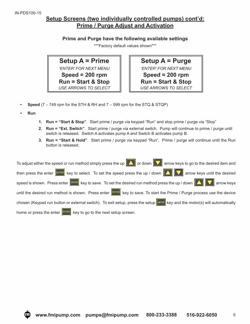
Setup Screens (two individually controlled pumps) cont’d:Prime / Purge Adjust and Activation
Prime and Purge have the following available settings***Factory default values shown***
Setup A = Prime‘ENTER’ FOR NEXT MENU
Speed = 200 rpmRun = Start & StopUSE ARROWS TO SELECT
Setup A = Purge‘ENTER’ FOR NEXT MENU
Speed = 200 rpmRun = Start & StopUSE ARROWS TO SELECT
• Speed (7 – 749 rpm for the STH & RH and 7 – 599 rpm for the STQ & STQP)
• Run
1. Run = “Start & Stop”. Start prime / purge via keypad “Run” and stop prime / purge via “Stop”2. Run = “Ext. Switch”. Start prime / purge via external switch. Pump will continue to prime / purge until
switch is released. Switch A activates pump A and Switch B activates pump B.3. Run = “Start & Hold”. Start prime / purge via keypad “Run”. Prime / purge will continue until the Run
button is released.
To adjust either the speed or run method simply press the up or down arrow keys to go to the desired item and
then press the enter key to select. To set the speed press the up / down arrow keys until the desired
speed is shown. Press enter key to save. To set the desired run method press the up / down arrow keys
until the desired run method is shown. Press enter key to save. To start the Prime / Purge process use the device
chosen (Keypad run button or external switch). To exit setup, press the setup key and the motor(s) will automatically
home or press the enter key to go to the next setup screen.
IN-PDS100-15
6www.fmipump.com [email protected] 800-233-3388 516-922-6050
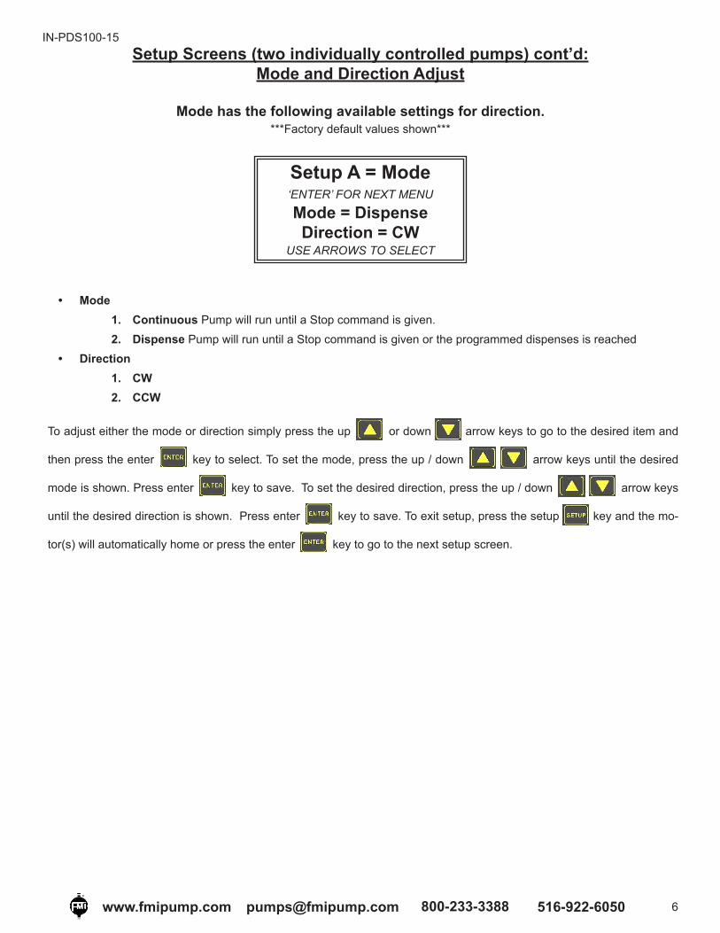
Setup Screens (two individually controlled pumps) cont’d:Mode and Direction Adjust
Mode has the following available settings for direction.***Factory default values shown***
Setup A = Mode‘ENTER’ FOR NEXT MENU
Mode = DispenseDirection = CW
USE ARROWS TO SELECT
• Mode1. Continuous Pump will run until a Stop command is given.2. Dispense Pump will run until a Stop command is given or the programmed dispenses is reached
• Direction1. CW2. CCW
To adjust either the mode or direction simply press the up or down arrow keys to go to the desired item and
then press the enter key to select. To set the mode, press the up / down arrow keys until the desired
mode is shown. Press enter key to save. To set the desired direction, press the up / down arrow keys
until the desired direction is shown. Press enter key to save. To exit setup, press the setup key and the mo-
tor(s) will automatically home or press the enter key to go to the next setup screen.

IN-PDS100-15
7www.fmipump.com [email protected] 800-233-3388 516-922-6050
Setup Screens (two individually controlled pumps) cont’d:Control and Start Method
Input has the following available settings for Input Control Type and Start Method***Factory default values shown***
Setup A = Inputs‘ENTER’ FOR NEXT MENU
Control = KeypadStart = Keypad
USE ARROWS TO SELECT
• Control (Speed) Speed can be adjusted prior to run command from one of the following 5 options listed below:1. RS485 2. 4-20 mA3. 0-10 V. (VDC)4. 0-5 V. (VDC)5. Keypad The pump speed can be adjusted via the keypad up/down arrow keys.
• Start The pumps can be activated (started) from one of the following 5 options listed below:1. RS485 2. Analog Pump(s) will start when a voltage is applied to the pump(s) Analog Input(s) based on Table 2,
pg. 12.3. Power Up The pumps will start to dispense / meter after power is applied. Note: The pumps initially
“home” prior to starting the dispense / metering process. In dispense mode the pumps will stop rotating once the desired dispense count is reached. The keypad stop button can also activate a stop command.
4. Switch Momentary closure will activate a pump in dispense mode. In continuous mode the pumps will only rotate while the switch is closed. Upon switch removal the pumps will complete rotating until “home” is reached.
5. Keypad The pump will start when the keypad start key is pressed, and stop when the stop
key is pressed.
To adjust either the control method or start method simply press the up or down arrow keys to go to the desired
item and then press the enter key. To set the control method, press the up / down arrow keys until the
desired control method is shown. Press enter key to save. To set the start method, press the up / down
arrow keys until the desired start method is shown. Press enter key to save. To exit setup, press the setup key
and the motor(s) will automatically home or press the enter key to go to the next setup screen.

IN-PDS100-15
8www.fmipump.com [email protected] 800-233-3388 516-922-6050
Setup Screens (two individually controlled pumps) cont’d:RS485 Setup
RS485 has the following available settings for Interface & Device Addresses***Factory default values shown***
Setup = RS485‘ENTER’ FOR NEXT MENU
Interface = 2 WireDevice Addr. = 5
USE ARROWS TO SELECT
• Interface 2 wire or 4 wire• Device Address Up to 31 (address #1 to #31) units can be independently addressed.
To adjust either the interface type or device address, simply press the up or down arrow keys to go to the
desired item and then press the enter key to select. To set the interface type press the up / down arrow
keys until the desired control method is shown. Press enter key to save. To set the Device Address press the up /
down arrow keys until the desired address is shown. Press enter key to save. The address selected
applies to both pumps in a dual pump system. To exit setup, press the setup key and the motor(s) will automatically
home or press the enter key to go to the next setup screen.

IN-PDS100-15
9www.fmipump.com [email protected] 800-233-3388 516-922-6050
Main Screen (both pumps in Dispense mode):Speed / Strokes adjust via keypad
Duo ModeUSE ARROWS TO SELECT
A = DispenseB = Dispense
PRESS ‘ENTER’ TO ADJUST
A = DispenseUSE ‘ENTER’ WHEN FINISHED
Speed = 200 rpmStrokes = 10
USE ARROWS TO ADJUST
Press the up / down arrow keys, then
the enter key to adjust the desired pump
Speed can be adjusted based on the control type selected from the Input Setup section in the manual. By default the PDS100 is configured for Keypad Control and Keypad Start.
A = DispenseUSE ‘ENTER’ WHEN FINISHED
Speed = 200 rpmStrokes = 10
USE ARROWS TO ADJUST
To adjust the speed, press the up arrow key and then press the enter key. Press the up / down
arrow keys to adjust, and then press the enter key when finished to save. To adjust the number of strokes, press
the down arrow key, and then press the enter key. Press the up / down arrow keys to adjust,
and then press the enter key when finished to save. Press the enter key one final time to go back to the main
screen.
Duo ModeUSE ARROWS TO SELECT
A = DispenseB = Dispense
PRESS ‘ENTER’ TO ADJUST
IN-PDS100-15
10www.fmipump.com [email protected] 800-233-3388 516-922-6050
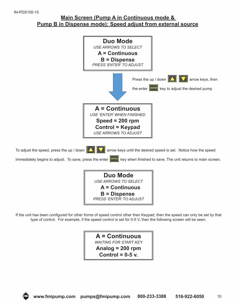
Main Screen (Pump A in Continuous mode & Pump B in Dispense mode): Speed adjust from external source
A = ContinuousUSE ‘ENTER’ WHEN FINISHED
Speed = 200 rpmControl = Keypad
USE ARROWS TO ADJUST
Duo ModeUSE ARROWS TO SELECT
A = ContinuousB = Dispense
PRESS ‘ENTER’ TO ADJUST
Press the up / down arrow keys, then
the enter key to adjust the desired pump
To adjust the speed, press the up / down arrow keys until the desired speed is set. Notice how the speed
immediately begins to adjust. To save, press the enter key when finished to save. The unit returns to main screen.
Duo ModeUSE ARROWS TO SELECT
A = Continuous B = Dispense
PRESS ‘ENTER’ TO ADJUST
If the unit has been configured for other forms of speed control other then Keypad, then the speed can only be set by that type of control. For example, if the speed control is set for 0-5 V, then the following screen will be seen.
A = ContinuousWAITING FOR START KEY
Analog = 200 rpmControl = 0-5 v.

IN-PDS100-15
11www.fmipump.com [email protected] 800-233-3388 516-922-6050
Analog Input Connector and Specifications
The PDS100 incorporates a simple screwless (spring loaded) terminal strip (see figure 6) for easy wire(22 to 14 AWG) connection to an external control source such as a PLC.
It is recommended that a DIN wire ferrule be used (See figure 5).
Figure 5Wire Ferrule
Table 1Analog / Switch Input Connector
Analog / Switch Input Terminal Strip
Signal Description
Shield Cable shield (terminate one end only)
Common Ground
Switch A Activates Prime, Purge and Start for Pump A when connected to Common and configured as such (TTL open collector or dry contact)
Switch B Activates Prime, Purge and Start for Pump B when connected to Common and configured as such (TTL open collector or dry contact)
Analog A Controls the speed of Pump A via an external voltage or current when configured as such(See Note 4 – Page 12)
Analog B Controls the speed of Pump B via an external voltage or current when configured as such(See Note 4 – Page 12)
Figure 6Analog Pump Control Connector (Rear Panel)

IN-PDS100-15
12www.fmipump.com [email protected] 800-233-3388 516-922-6050
Analog Input Connector and Specifications (cont’d)
Figure 7Input Resistance Schematic (Analog input: 0 – 5 VDC or 0 – 10 VDC)
Table 2Input Voltage / Current Versus RPM
NOTES
RPM
4 - 20 (mA)Input
Resistance 490 ohms
(Note 1,3,4)
0 - 5 (VDC) (Note 1,2,4)
0.5 - 10 (VDC)(Note 1 2,4) Analog Input
Min Max Min Max Min Max Min Max 4 - 20 mA 0 - 5 VDC 0 - 10 VDC
Standard H Pump
6
750
1.6 20 0.2 5 0.2 10 See Waveforms 1 to 9Standard Q Pump 600
Standard STQP Pump 700
Note 1: Maximum current is reduced provided control method is set according to actual input method (ie 0 – 5 VDC or 0 – 10 VDC). If desired control method is set for “4–20mA” but a 0 – 5 VDC or 0 – 10 VDC is applied the maximum current will be at its greatest.
Note 2: Absolute maximum input voltage is 10.8 VDC
Note 3: Absolute maximum current is 22 mA
Note 4: When start is set to “Analog”, it is important to switch voltage / current on only when above the minimum to properly start the pump(s). It is equally important to switch voltage off rather then slowly ramping the voltage / current down below the minimum. It is not recommended to gradually raise / lower the input voltage / current to start / stop the pump(s).
When start / stop is controlled via the analog input, the pump(s) will stop when the analog input goes below the minimum voltage / current. The pumps will run when the minimum voltage / current is reached and will run at the minimum speed.
IN-PDS100-15
13www.fmipump.com [email protected] 800-233-3388 516-922-6050
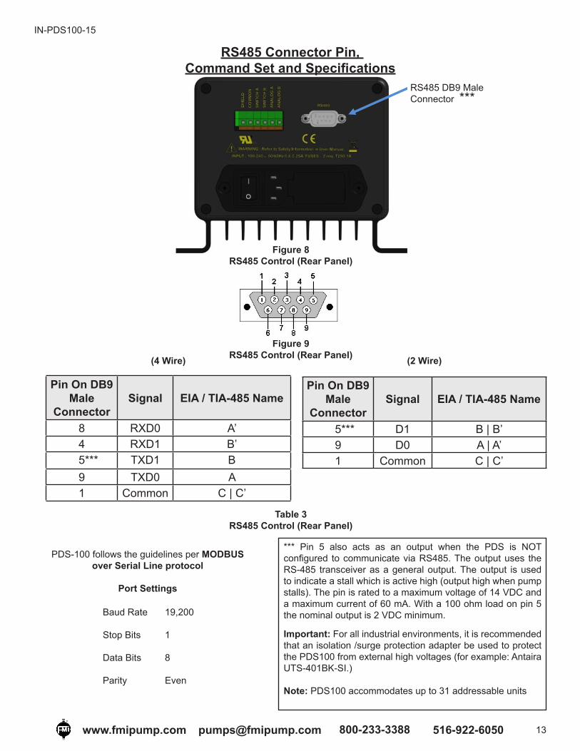
Pin On DB9 Male
ConnectorSignal EIA / TIA-485 Name
5*** D1 B | B’9 D0 A | A’1 Common C | C’
Pin On DB9 Male
ConnectorSignal EIA / TIA-485 Name
8 RXD0 A’4 RXD1 B’5*** TXD1 B9 TXD0 A1 Common C | C’
RS485 Connector Pin, Command Set and Specifications
RS485 DB9 Male Connector ***
(4 Wire)
Figure 8RS485 Control (Rear Panel)
Figure 9RS485 Control (Rear Panel)
Table 3RS485 Control (Rear Panel)
Baud Rate 19,200
Stop Bits 1
Data Bits 8
Parity Even
PDS-100 follows the guidelines per MODBUS over Serial Line protocol
Port Settings
*** Pin 5 also acts as an output when the PDS is NOT configured to communicate via RS485. The output uses the RS-485 transceiver as a general output. The output is used to indicate a stall which is active high (output high when pump stalls). The pin is rated to a maximum voltage of 14 VDC and a maximum current of 60 mA. With a 100 ohm load on pin 5 the nominal output is 2 VDC minimum.
Important: For all industrial environments, it is recommended that an isolation /surge protection adapter be used to protect the PDS100 from external high voltages (for example: Antaira UTS-401BK-SI.)
Note: PDS100 accommodates up to 31 addressable units
(2 Wire)

IN-PDS100-15
14www.fmipump.com [email protected] 800-233-3388 516-922-6050
Command MappingSingle bit read and write. Set bit to initiate action, PDS-100 will clear bit upon executionCoil 0 = “start” > Pump A – (all configurations except individual – individual pump A only)Coil 1 = “stop” > Pump A – (all configurations except individual – individual pump A only)Coil 2 = “start-2” > Pump B – (individual configuration only)Coil 3 = “stop-2” > Pump B – (individual configuration only)
Single bit status, read onlyInput 0 = “busy” > Pump A – (all configurations except individual – individual pump A only)Input 1 = “error” > Pump A – (all configurations except individual – individual pump A only)Input 2 = “busy-2” > Pump B – (individual configuration only)Input 3 = “error-2” > Pump B – (individual configuration only)
16 bit word read and write. Not allowed to change when pump is busyHolding Register 0 = “rpm” > Pump AHolding Register 1 = “stroke count” > Pump AHolding Register 2 = “rpm-2” > Pump BHolding Register 3 = “stroke count-2” > Pump B
16 bit word information read onlyInput Register 0 = “configuration” *see configuration tableInput Register 1 = “operating mode” 0=continuous, 1=dispenseInput Register 2 = “operating mode-2” 0=continuous, 1=dispenseInput Register 3 = “error code” 0= no error, 1= errorInput Register 4 = “error code-2” 0= no error, 1= errorInput Register 5 = “minimum-speed”Input Register 6 = “maximum-speed”
Configuration Table Drive CodeSingle (RH) 16384
Single (STH) 16385Single (STQ) 16386Single (STQP) 16387Individual (RH) 49152Individual (STH) 49153Individual (STQ) 49154Individual (STQP) 49155In phase (RH) 49664In phase (STH) 49665In phase (STQ) 49666In phase (STQP) 49667Out of phase (RH) 50688Out of phase (STH) 50689Out of phase (STQ) 50690Out of phase (STQP) 50691Smooth (RH) 52736Smooth (STH) 52737Smooth (STQ) 52738
Smooth (STQP) 52739

IN-PDS100-15
15www.fmipump.com [email protected] 800-233-3388 516-922-6050
Configuration Modes Screens
(Appears when Up Arrow and Setup Keys are held down while powering up unit)The unit comes pre-configured as a Dual Individual system when purchased as a dual pump system. To configure the dual pump system for “In Phase” operation or “Out Phase” operation follow the procedure mentioned above to modify. If the unit supplied is a single pump system there is no need to change the configuration.
Possible drive configurations types supported (configured by factory):
1. Single: Single pump
* 2. Individual: Two pumps that can be controlled independently
3. In Phase: Two pumps that are in phase with each other
4. Out of Phase: Two pumps that run 180 degrees out of phase for each other
5. Smooth: Requires factory calibrated pump drive assembly Not covered in this manual.
* Default Setting
The following screens will be seen when entering the configuration mode. The configuration mode can only be entered if
the up arrow key and setup keys are held down while powering on the unit. After configuration selection is
made, press Setup for changes to take effect.
PDS100Configuration
Setup
SoftwareVersion
Setup = Mode‘ENTER’ FOR NEXT MENU
Pump = RHDrive = Out Phase
USE ARROWS TO SELECT
IN-PDS100-15
16www.fmipump.com [email protected] 800-233-3388 516-922-6050
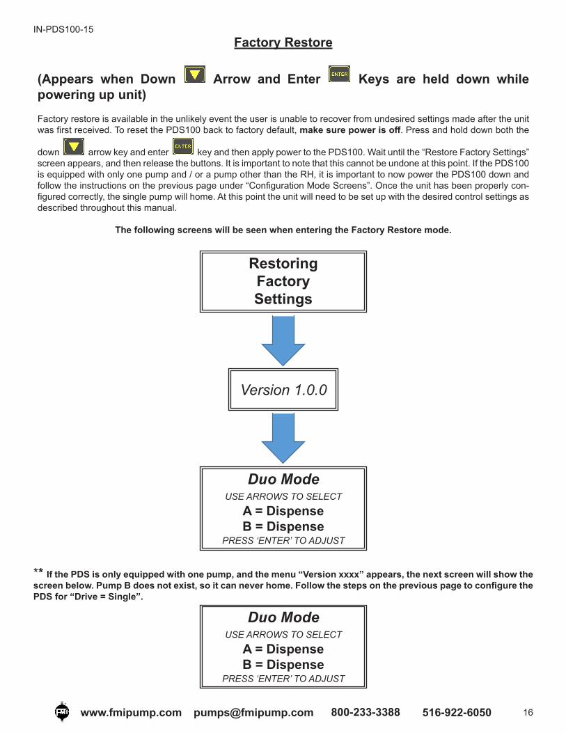
Factory Restore
(Appears when Down Arrow and Enter Keys are held down while powering up unit)Factory restore is available in the unlikely event the user is unable to recover from undesired settings made after the unit was first received. To reset the PDS100 back to factory default, make sure power is off. Press and hold down both the
down arrow key and enter key and then apply power to the PDS100. Wait until the “Restore Factory Settings” screen appears, and then release the buttons. It is important to note that this cannot be undone at this point. If the PDS100 is equipped with only one pump and / or a pump other than the RH, it is important to now power the PDS100 down and follow the instructions on the previous page under “Configuration Mode Screens”. Once the unit has been properly con-figured correctly, the single pump will home. At this point the unit will need to be set up with the desired control settings as described throughout this manual.
The following screens will be seen when entering the Factory Restore mode.
RestoringFactorySettings
Version 1.0.0
Duo ModeUSE ARROWS TO SELECT
A = DispenseB = Dispense
PRESS ‘ENTER’ TO ADJUST
Duo ModeUSE ARROWS TO SELECT
A = DispenseB = Dispense
PRESS ‘ENTER’ TO ADJUST
** If the PDS is only equipped with one pump, and the menu “Version xxxx” appears, the next screen will show the screen below. Pump B does not exist, so it can never home. Follow the steps on the previous page to configure the PDS for “Drive = Single”.

IN-PDS-100-15
17www.fmipump.com [email protected] 800-233-3388 516-922-6050
Table 4Pump Operating Parameters
Waveform #1 Waveform #2

IN-PDS-100-15
18www.fmipump.com [email protected] 800-233-3388 516-922-6050
Waveform #3
Waveform #6Waveform #5
Waveform #4

IN-PDS-100-15
19www.fmipump.com [email protected] 800-233-3388 516-922-6050
Waveform #7 Waveform #8
Waveform #9