Embed Size (px)
Citation preview
ALESIS
Studio 12R Reference Manual

Table of Contents
Studio 12R Reference Manual 1
TABLE OF CONTENTS
Table of Contents .................................................................1
Important Safety Instructions................................3Safety symbols used in this product............................................................3Please follow these precautions when using this product:....................3
Introduction.............................................................................5The Alesis Studio 12R Microphone Preamplifier/Mixer ......................5Using this manual..........................................................................................5Grounding Instructions.................................................................................6
Installation ...............................................................................7Unpacking ........................................................................................................7AC power..........................................................................................................7
Grounding............................................................................................7Use clean power ..................................................................................8Power switch........................................................................................8
Mounting..........................................................................................................8
Connections .............................................................................9Inputs.................................................................................................................9
Cable common sense..........................................................................9Microphone Inputs...........................................................................10Phantom power.................................................................................11Line-level devices (synthesizers, CD players, video) ................12TAPE IN jacks....................................................................................14Phonograph turntables....................................................................15Do not connect any of the following to any input of theStudio 12R!.........................................................................................15
How to connect effect devices and signal processors ............................16Effects via Aux Send and Aux Return .........................................16In-line processing using the INSERT jacks (compressors &equalizers)...........................................................................................17
Outputs............................................................................................................20To a stereo PA system or instrument amplifier.........................20To a mono system.............................................................................20To a stage monitor (foldback) system ...........................................20To another mixer..............................................................................21To a stereo tape recorder..................................................................21To an ADAT multitrack recorder..................................................22Phones.................................................................................................25Monitor Out.......................................................................................25

Table of Contents
Studio 12R Reference Manual 2
Operating Instructions......................................................27Before turning the mixer on, "zero out' the controls...........................27Setting input trim levels.............................................................................28
PEAK LED method ...........................................................................28Metering/Unity Gain method .......................................................29
Typical Fader and Control Levels..............................................................30Proper gain staging of other equipment ......................................31
AUX System: Effects Send/Receive .........................................................32How to Set Aux Send and Return Levels....................................32
Using the meter.............................................................................................34Avoiding noise..............................................................................................35
System noise (ground loops, hum, induced noise)...................35
Applications...........................................................................39Multitrack recording ....................................................................................39
Tracking/Overdubbing....................................................................39Mixdown.............................................................................................40
Using the HIGH and LOW EQ controls ...................................................41Monitoring AUX 1 in the PHONES jack .................................................42
Troubleshooting..................................................................43Troubleshooting Index ................................................................................43Maintenance/Service...................................................................................45
Exterior cleaning ...............................................................................45Obtaining Repair Service ................................................................45
Specifications .......................................................................47Frequency Response.....................................................................................47Connectors......................................................................................................47Levels...............................................................................................................48Impedance ......................................................................................................48Noise performance (typical) .......................................................................49Distortion (THD+N).....................................................................................49Power...............................................................................................................49Mounting........................................................................................................49
Dimensional Drawing ........................................................50
Block diagram ......................................................................51Level diagram................................................................................................52
Index ........................................................................................53
Warranty ...............................................................................54

Important Safety Instructions
Studio 12R Reference Manual 3
IMPORTANT SAFETYINSTRUCTIONS
Safety symbols used in this product
This symbol alerts the user that there are important operating and maintenance instructions in the literature accompanying this unit.
This symbol warns the user of uninsulated voltage within the unit that can cause dangerous electric shocks.
Please follow these precautions whenusing this product:
1. Read these instructions.
2. Keep these instructions.
3. Heed all warnings.
4. Follow all instructions.
5. Do not use this apparatus near water.
6. Clean only with a damp cloth. Do not spray any liquid cleaner onto thefaceplate, as this may damage the front panel controls or cause adangerous condition.
7. Install in accordance with the manufacturer's instructions.
8. Do not install near any heat sources such as radiators, heat registers,stoves, or other apparatus (including amplifiers) that produce heat.
9. Do not defeat the safety purpose of the polarized or grounding-type plug.A polarized plug has two blades with one wider than the other. Agrounding-type plug has two blades and a third grounding prong. Thewide blade or the third prong are provided for your safety. When theprovided plug does not fit into your outlet, consult an electrician forreplacement of the obsolete outlet.

Important Safety Instructions
Studio 12R Reference Manual 4
10. Protect the power cord from being walked on or pinched, particularly atplugs, convenience receptacles, and the point where they exit from theapparatus.
11. Use only attachments or accessories specified by the manufacturer.
12. Use only with a cart, stand, bracket, rack, or table designed for use withprofessional audio or music equipment. In any installation, make surethat injury or damage will not result from cables pulling on the apparatusand its mounting. If a cart is used, use caution when moving thecart/apparatus combination to avoid injury from tip-over.
13. Unplug this apparatus during lightning storms or when unused for longperiods of time.
14. Refer all servicing to qualified service personnel. Servicing is requiredwhen the apparatus has been damaged in any way, such as when thepower-supply cord or plug is damaged, liquid has been spilled or objectshave fallen into the apparatus, the apparatus has been exposed to rain ormoisture, does not operate normally, or has been dropped.
15. This unit produces heat when operated normally. If this unit is installedin a rack, make sure that there is proper ventilation when operated. Donot operate with the rack covers on. If there are other units in the rackthat generate a large amount of heat, spread them apart. Do notsandwich this product between to large heat-producing units.
16. This product, in combination with an amplifier and headphones orspeakers, may be capable of producing sound levels that could causepermanent hearing loss. Do not operate for a long period of time at ahigh volume level or at a level that is uncomfortable. If you experienceany hearing loss or ringing in the ears, you should consult an audiologist.

Introduction
Studio 12R Reference Manual 5
INTRODUCTIONThe Alesis Studio 12R MicrophonePreamplifier/Mixer
The Alesis Studio 12R is a high-quality, rack-mountable 12-input,stereo output audio mixer. It is designed to handle eightmicrophones, two stereo line inputs, and to route signal to andfrom external effect processing devices. As a basic, easy-to-understand mixer, it can be used in a wide variety of applicationsfrom sound reinforcement to multitrack recording. It may also beused as an accessory or submixer to a larger console.
Using this manualTo get the most out of your Studio 12R, please read this manual.While the mixer is not complicated to operate, the manual containsinformation that will help you get the highest level of performancefrom it. We’ve included creative alternative techniques that aren'tobvious at first glance.
To find what you need quickly, refer to the index at the back of themanual, or the Table of Contents.
We appreciate your feedback. If you have any suggestions on howto improve this manual, please write to us at:
Technical Communications Dept.Alesis Corp.3630 HoldregeLos Angeles, CA 90016
or via email at: [email protected]
Conventions
The buttons, knobs, and rear panel connectors are referred to in thismanual just as their names appear on the Studio 12R, using allcapital letters (Example: [TRIM] control, [PAN] knob, [PHONES]jack, etc.).
When something important appears in the manual, an icon (likethe one on the left) will appear in the left margin. This symbol

Introduction
Studio 12R Reference Manual 6
indicates that this information is vital when operating the Studio12R.
Grounding InstructionsThis product must be grounded. If it should malfunction or breakdown, grounding provides a path of least resistance for electriccurrent to reduce the risk of electric shock. This product is equippedwith a cord having an equipment-grounding conductor and agrounding plug. The plug must be plugged into an appropriateoutlet that is properly installed and grounded in accordance with alllocal rules and ordinances.
DANGER - Improper connection of the equipment-groundingconductor can result in a risk of electric shock. Check with aqualified electrician or serviceman if you are in doubt as to whetherthe product is properly grounded. Do not modify the plug providedwith the product; if it will not fit the outlet, have a proper outletinstalled by a qualified electrician.

Installation
Studio 12R Reference Manual 7
INSTALLATIONUnpacking
The Studio 12R box should contain:1. The mixer itself2. A packet of literature along with this manual3. An AC power cable4. An Alesis warranty card
Please send in your warranty card right away. Your warranty is not registeredwith Alesis until the card is returned. Please save your sales receipt as your ultimate proofof purchase and warranty date. By sending in your warranty card, you will receive theAlesis First Reflection magazine free of charge, and we will be able to notify you of specialprograms and offers from Alesis. Should repair ever become necessary, having the unitregistered will make it faster and easier to obtain service.
Note that the warranty is valid only in the country of purchase; i.e., units purchased in theUnited States must be serviced in the United States.
AC powerREAD ALL SAFETY WARNINGS IN THE PREVIOUS SECTION OF THIS MANUALTO ENSURE SAFE OPERATION OF THIS UNIT. Connect the Studio 12R to thespecified power using the AC cable supplied with the unit. The AC cable is removable. Ifthe distance to your AC outlet is longer or shorter than the supplied cable, you maysubstitute an approved standard NEMA-to-CEE power cable of the correct length, availablefrom most electronics stores.
Grounding
CONNECT THE STUDIO 12R TO A PROPERLY GROUNDED OUTLET ONLY. DONOT USE ADAPTERS WHICH REMOVE THE SAFETY GROUND PROTECTION ORCUT OFF THE GROUNDING PRONG ON THE POWER CORD. Proper grounding isessential for user safety and low noise. If you experience 60-cycle hum in your soundsystem as a result of different ground potentials between different units in your system,plug all units into the same AC circuit (if the total power load allows) and make sure otherdevices in the system are properly grounded themselves. The Studio 12R features balancedinputs and outputs, so if it is properly connected to other balanced units, AC groundpotentials will not affect the audio. If you cannot get rid of ground loops, consult aprofessional electrician familiar with sound system power designs.
Use clean powerThe Studio 12R's internal power supply is designed to filter out most AC line noise.However, it is still good practice to plug your sound equipment into an AC circuit that isnot shared with lighting dimmers, refrigerators, air conditioning units, or other appliancesthat may induce noise into the power system.

Installation
Studio 12R Reference Manual 8
Power switch
The POWER switch is located on the back panel. A power indicatoris on the front panel next to the meter. Avoid turning the powerswitch on or off while the Studio 12R is connected to a liveamplifier.
MountingThe Studio 12R may be rack mounted in a standard EIA 19" rack, occupying three standard1.75" rack spaces. Any angle of orientation is acceptable. Note that (as with most audioequipment) if it is mounted into metal rack rails, the chassis ground of all units in the rackwill be connected together by the rail. In some cases this is desirable, but if hum is aproblem in the system, you may need to install non-conductive rack screws and washers onthe Studio 12R or other equipment in the rack to isolate the chassis grounds from eachother.
The mixer may also be used on a table top. To avoid scratching a tabletop surface, applyrubber or felt feet to the bottom of the Studio 12R.

Connections
Studio 12R Reference manual 9
CONNECTIONSInputs
Cable common senseMake all connections to the Studio 12R with the power turned off whereverpossible. If you must connect or disconnect inputs while power is on, make sure thechannel fader and [TRIM] are turned all the way down to avoid sudden pops and clickswhich may damage speakers or other equipment.
Use good-quality cable: 99% of all mixer problems turn out to becable or connector problems. Use the best quality cable you can, forhighest reliability and lowest noise. If something goes wrong, checkthe cable and its connection to the mixer first. If the connectors aredirty or corroded, clean them with isopropyl alcohol or otherapproved electrical contact cleaner before inserting them into theStudio 12R. High quality cables are low-capacitance shielded cableswith a stranded (not solid) internal conductor and a low-resistanceshield. Although quality cables cost more, they do make adifference.
Route cables in your system correctly by observing the followingprecautions:
• Do not bundle audio cables with AC power cords.
• Avoid running audio cables, or placing the Studio 12R itself,near sources of electromagnetic interference such astransformers, monitors, computers, etc.
• Never unplug a cable by pulling on the wire itself. Alwaysunplug by firmly grasping the body of the plug and pullingdirectly outward.
• Do not place cables where they can be stepped on. Stepping on acable may not cause immediate damage, but it can compress theinsulation between the center conductor and shield (degradingperformance), or reduce the cable’s reliability.
• Avoid twisting the cable or having it make sharp, right angleturns.
Microphone InputsThe Alesis Studio 12R features eight studio-grade, low-noise hybrid microphonepreamplifiers. These [MIC] jacks are designed to work with almost any low-impedance

Connections
Studio 12R Reference manual 10
microphone using standard 3-conductor XLR connectors. The [MIC] jacks also feature 48volt phantom power, which may be turned on and off by the [PHANTOM] switch on theback panel, for condenser microphones which require external powering.
Balanced Mic Input
GroundHot12
3
Cold
Socket (female)
The MIC Input is designed to accept a wide range of balanced or unbalanced lowimpedance input signals, with up to 60 dB of amplification available (which is 10 to 20 dBmore than many other rack-mount mixers). It is wired with "pin 2 hot" according to theaccepted standard.
Use only one input per channel. The LINE IN jack and the MIC IN jack of achannel can’t be used at the same time. If you turn up the level of a line source to hear it atthe same time a microphone is connected, you may damage the microphone.

Connections
Studio 12R Reference manual 11
Phantom powerCertain types of microphones (called condenser microphones) require a DC power supplyfrom the mixer. “Phantom power” sends 48 volts of DC through the microphone cable. Ifany of your microphones need phantom power, turn on the [PHANTOM POWER] switchon the Studio 12R’s back panel to connect all the XLR MIC IN jacks to the Studio 12R’sinternal 48 volt phantom power source. Since the power is applied equally to pins 2 and 3,phantom power should not affect dynamic microphones (which do not require phantompower). However, make sure that your microphone cables have no short circuits orintermittent connections to avoid damage to the system.
Avoid connecting or disconnecting any microphones while [PHANTOMPOWER] is turned on. Make all connections with the Studio 12R powered off. If thisis not possible, make sure the channel's fader and [TRIM] are down, make theconnections, then turn on the [PHANTOM POWER] switch on the back panel beforebringing the fader and [TRIM] back up. Many microphones make a loud "pop" when firstpowered, so make sure your faders are down to avoid damaging your speakers or hearing.
Never connect the MIC jack to an UNBALANCED source or to aline-level device (such as a tape recorder or synthesizer) whenphantom power is being used.
If none of your microphones need phantom power, leave the phantom power switch off.

Connections
Studio 12R Reference manual 12
Line-level devices (synthesizers, CD players,video)
The Studio 12R features line-level inputs on 1/4" phone jacks which accept standardunbalanced or balanced signals.
AAAAAAAAAAAAAA
Tip
Sleeve
Signal
Ground
Tip
Sleeve
Unbalanced Line Input
AAAAAAAAA
Tip
Sleeve
Hot
Ground
Tip
Sleeve
Balanced Line Input
Ring
Ring
Cold
Unbalanced -10 dBV line level sources: Most synthesizers, drum machines, effectdevices, cassette decks and CD players operate at this level. Their average signal level isabout 1/3 of a volt. They have a 2-conductor output jack that is either a 1/4" phone or"RCA phono" type. These may be plugged directly into any of the Studio 12R’s [LINEIN] jacks, with the [TRIM] level set at approximately the 1 o'clock position. Plug stereosources such as synthesizers, CD players, and drum machine main outputs into theSTEREO LINE channels (9/10 and 11/12) if possible.
Electric guitars and basses may be plugged directly into the [LINE IN] jacks, if youraise the [TRIM] level. The Studio 12R has more than enough gain (up to 50 dB when thechannel fader and trim are set to maximum) for guitars, although some pickups may soundbetter if they're plugged directly into a high-impedance preamp designed for guitar use.Plug the output of such preamps into any [LINE IN] jack.
A reminder: do not plug a line input and a microphone input into the samechannel. The inputs are not designed to handle two sources at the same time. If youcrank up the line level input to extremes to compensate for the level loss, you may damagethe microphone.

Connections
Studio 12R Reference manual 13
Balanced +4 dBu line level sources: Professional recording and processingequipment typically provides a balanced, 3-conductor signal output that is a higher voltage(1.24 volts nominal level) than most synthesizers and stereo equipment. The Studio 12R’s[LINE IN] jacks are designed to handle these balanced inputs.
Balanced sources often feature XLR outputs. However, they should NOT be connected tothe XLR [MIC] inputs of the Studio 12R unless absolutely necessary, because the highergain of the MIC jacks gives you less headroom than the LINE IN jacks do (also, the sourcecould be damaged by phantom power if it's turned on). Connect them to the [LINE IN]jacks using an XLR-to-1/4 inch phone TRS (tip-ring-sleeve) cable, as shown below:
If the proper connector cable or adapter is not available, +4 dBu line level sources may beconnected to the [MIC] jacks ONLY IF PHANTOM POWER WILL NOT BEUSED!!
Connecting a line-level output to a phantom-powered XLR inputon the Alesis Studio 12R may cause damage to the external unit.Alesis cannot be responsible for any damages caused by this kind ofmisuse.
The nominal trim setting for a +4 dBu signal plugged into a line input is approximately 11o'clock (12 o'clock on the stereo channels). This will give you plenty of headroom to startwith.
Maximum levels: The maximum level the [MIC] jack can receive with the [TRIM]control full counter-clockwise is +12 dBu before clipping, so there’s only 8 dB ofheadroom if you plug a +4 dBu line source into the mic jack. The [LINE IN] jack onchannels 1-8 may receive levels up to +32 dBu without clipping, a headroom advantage of20 dB. The stereo channels may receive a +22 dBu (balanced or unbalanced) maximuminput.

Connections
Studio 12R Reference manual 14
TAPE IN jacks
The [TAPE IN] jacks on the rear panel are designed for playback of astereo tape deck (or any other -10 dBV level signal) through the[MONITOR OUT] and [PHONES] jacks only. A signal at the [TAPEIN] jacks cannot be heard from the [MAIN OUT] jacks.
This allows you to use the Studio 12R to monitor a mixdown to a 2-track deck through your headphones. (If you plugged yourmixdown deck into the line inputs on the channels, it would causefeedback when you press “record”.) By placing the[PHONES/MONITOR] switch in the TAPE position, you will hearthe mixer's output after it has been passed through the mixdowndeck, so you can make sure that it is recording correctly.
• Another use for the [TAPE IN] jacks is to play a CD or tape into aPA system, automatically turning off all the microphones intothe main PA system when the front panel MSTR/TAPE switchis set to the TAPE position. Note that in this application, the PAsystem must be fed from the MONITOR OUT instead of theMAIN OUT jacks, and will be affected by the level of the[PHONES/MONITOR] control as well as by the [MASTER]control fader.

Connections
Studio 12R Reference manual 15
Phonograph turntablesIf you're using a record turntable, you may not plug it directly into the line inputs of theStudio 12R (well, you can, but it will sound very thin and noisy). Obtain a phono preampfrom your dealer or an electronics specialty store.
1. Plug the outputs of the phonograph pickup into the RIAA-equalized phono preamp.
2. Plug the outputs of the preamp into the LINE IN 9-10 or 11-12inputs of the Studio 12R.
Do not connect any of the following to anyinput of the Studio 12R!
• The speaker output of any power amplifier.
• Any source that is too loud for the input (no more than 3 voltsRMS into a [MIC] jack or 13 volts RMS into a [LINE IN] jack).
• Any unshielded cable.

Connections
Studio 12R Reference manual 16
How to connect effect devices and signalprocessorsAlesis and other companies make many different types of signal processors which may beconnected to the Studio 12R mixer. There are two ways to connect these units: using theAUX system or via the INSERT jacks.
Effects via Aux Send and Aux ReturnIf you want to add an effect such as reverb, chorus, or delay to several different inputs atonce, you will use the AUX system.
1. Connect the AUX 2 (POST) AUX SEND output of the 12R to theinput of the effect device. If the effect has a stereo input, checkthe manual of the effect to see which jack is the mono jack. (Inmost cases, you won't need to connect anything to the otherinput jack of the device, but you will still get a stereo effectoutput).
2. Connect the left and right outputs of the effect device to the[STEREO AUX RETURN] jacks of the Studio 12R.
• Alternatively, you may connect the output of the effect device toeither of the STEREO LINE channels ([9-10 or 11-12].) This willallow you to control the effect with a large fader, send the effectsto the Aux 1 output for monitoring, and use EQ on the effect.
About stereo effect devices
If your effect unit has two inputs, in most cases you need to connectfrom only ONE Aux Send to the left (mono) input of the effect unit,but you will still connect both the left and right outputs of the effectto the STEREO AUX RETURN.

Connections
Studio 12R Reference manual 17
You don’t need to connect anything to the other input of the effect,because most effect units use the stereo inputs only to provide apath for the “dry” stereo signal when the effect is connected directlybetween an instrument and an amplifier. In mixing applicationssuch as with the Studio 12R, you will set the effect’s wet/dry balanceall the way to “wet” (effects only, no direct signal). The effect devicewill generate an artificial stereo output from the signal input.Check the manual for your effect device for more information.
On the other hand, true dual-channel effects processors (such as theAlesis QuadraVerb 2) may be connected to two different sends totake advantage of the dual processing capability. Dual-channelprocessors allow the left and right inputs to be used for differentkinds of effects (for example, the left input to a stereo chorus whilethe right input is used for a stereo reverb).
Using Aux 1 as an effects send
Note that [AUX 1] may also be used as an extra effects send.Although Aux 1 is a pre-fader send, and normally used for stagemonitoring or a separate headphone mix while recording, it mayalso be used as an effects send so you can add different effects todifferent channels. Just remember that the “PRE” under [AUX 1]means that when you move a fader up or down you won’t changethe level going to an effect from Aux 1. If you change fader levels,you will need to adjust Aux 1 levels to maintain the same balancebetween dry and effected signal.
In-line processing using the INSERT jacks(compressors & equalizers)
Some signal processors are designed to be used on one signal at a time, with the entiresignal being processed instead of a mix of effected and uneffected signal. The purpose ofthe INSERT jacks on channels 1-8 is to allow you to insert a compressor, equalizer, orother effect into the signal path of a single channel after its preamplifier and [TRIM]control, but before the Studio 12R's own EQ, aux sends, and fader. The INSERT jacksmay also be used as direct outputs to a recorder.
The INSERT connector is a TRS (tip/ring/sleeve) 1/4" jack whichconsists of an insert send (the tip of the TRS plug) and an insertreturn (the ring of a TRS plug). A special Y-cable consisting of aTRS 1/4" plug on one end and two mono 1/4" plugs on the otherend is required.

Connections
Studio 12R Reference manual 18
Tip
Ring
Sleeve
Send
Return
Ground
Tip
Ring Sleeve
Insert Points
Note that you will not hear any signal through the Studio 12R if theINSERT jack is plugged in and the signal is interrupted in that loop (by theother cables being disconnected, the processor being turned off, or the volume turned off inthe processor).
Connecting an in-line processor
1. Obtain a "stereo splitter" insert cable from your dealer.
2. Connect the stereo (TRS) end to the INSERT jack of the Studio12R.
3. Connect the mono plug from the tip connector to the input ofthe processor.
4. Connect the mono plug from the ring connector to the output ofthe processor.
If you're not sure which mono plug is from the tip and which is from the ring, check to seeif the cable is labeled. If not, simply try it one way and if the signal doesn't pass through,swap the input and output plugs the other way.
• The [INSERT] jack may also be used as a direct output to amultitrack recorder such as the ADAT. The send from the insertjack is where the cleanest mic preamp signal may be obtained,without passing through the EQ or channel circuitry. Simply insertthe plug to the first "click" (the ring connector) and it will notinterrupt the flow through the mixer, while providing a directoutput. Or, put the recorder into INPUT mode and insert the plugall the way, connecting the input and output of each track of the

Connections
Studio 12R Reference manual 19
recorder into each channel path of the mixer. This will allowplayback monitoring of the recorder. See the Applications chapterfor more information.
For more information on using the AUX and INSERT systems, see the“Operating Instructions” chapter of this manual.

Connections
Studio 12R Reference manual 20
Outputs
To a stereo PA system or instrumentamplifier
Balanced
Check to see if your amplifier can accept balanced inputs. If so,connect the [MAIN OUT BALANCED] jacks of the Studio 12R to theinput of the amp using a 3-conductor cable, with a 1/4" TRS plug onone end, and the connector used by the amp (usually a 1/4" TRSconnector; sometimes an XLR or terminal strip) on the other.
• You may also connect the [MONITOR OUT] jacks of the mixer toyour amplifier. This will allow you to switch between hearing 2-track playback and the stereo output of the mixer, using the frontpanel monitor switch.
Unbalanced
If the amp is unbalanced, use a standard shielded "patch cord" with1/4" connectors.
To a mono system
If your PA system or amplifier isn't stereo, connect either the left orright MAIN OUT jacks to the input of the system. Make sure thatall [PAN] controls are in the center or turned to the side you'reusing.
To a stage monitor (foldback) systemIf your PA system has a separate amplifier and speaker system for monitors, connect acable from the [AUX 1 PRE AUX SENDS] jack to the amp input, in the same manner asabove. The Aux 1 system is a pre-fader, post-EQ send with a balanced/unbalanced output.In most stage monitor situations, we recommend connecting a third-octave graphicequalizer such as the Alesis MEQ-230 between the mixer and the amp to control feedback.
The Aux 1 output may be connected in the same way for a number of different applicationssuch as:
• Headphone cue feed for multitrack recording• Separate broadcast mix from a PA system• Zone feed for a separate region of a PA system

Connections
Studio 12R Reference manual 21
To another mixer
The main or monitor outputs of the Studio 12R may be connectedto a larger mixing console. Consult the manual for the other mixerfor more information. If the mixer has "SUB IN" jacks, connect tothose. Alternatively, you may simply connect the MAIN OUT orMONITOR OUT jacks of the Studio 12R to two line-level inputs onthe other mixer. If you do, check to see what level those inputs aredesigned for.
• If the inputs of the other mixer can handle +4 dBu balanced or -2dBu unbalanced levels, simply connect the [MAIN OUTBALANCED] outputs to the other mixer's line inputs.
• If the inputs are designed for -10 dBV level inputs (such as mostkeyboard and guitar amplifiers, and consumer stereo amplifiers),connect the [MAIN OUT -10 dBV] outputs to the line inputs ofthe external mixer.
If the connection is made properly, the Studio 12R will not distortthe input of the other mixer. You may need to adjust the inputtrim of the other mixer to get the best dynamic range.
To a stereo tape recorder
If you want to record the output of the mixer into a typical stereocassette or DAT deck, connect the [MAIN OUT -10 dBV] phono jacksto the left and right inputs of the cassette deck using a standardstereo phono-to-phono (RCA) cable.
If your recorder is a professional type with balanced +4 inputs, inmost cases you should connect the [MAIN OUT BALANCED] jacksof the mixer to the inputs of the recorder.
• If you connect the [MONITOR OUT] jacks to the recorder, thelevel will be affected by the [PHONES/MONITOR] level control onthe front panel. However, if you're using the [TAPE IN] jacks tomonitor playback, you run the risk of feedback if you press theMSTR/TAPE switch while in record mode.

Connections
Studio 12R Reference manual 22
To an ADAT multitrack recorder
The studio-grade microphone preamplifiers of the Studio 12R aredesigned to rival or exceed the sound quality of externalmicrophone preamps costing many times more. A basic 8-trackdigital recording system with an ADAT-XT and a Studio 12R isportable, cost-effective, easy to use, and sonically transparent. Thereare two ways to use the Studio 12R with ADAT: a single mixer withthe ADAT patched into the [INSERT] jacks, or using two Studio12Rs, one for input and another for monitoring.
In-line ADAT recording:
In this hookup method, the ADAT is patched into the [INSERT] jacks of channels 1-8 as ifeach track of the recorder were a signal processor in each channel of the mixer. Since theADAT is a unity-gain device, it will not affect the levels going through the mixer. The[TRIM] control is the only level control for the ADAT inputs; the channel faders, EQ, andaux sends of the Studio 12R are used for monitoring and will not affect multitrackrecording levels.
This method is recommended by many audiophiles and engineers, since there is a minimumof circuitry between the original source and the recorder. Hooking a Studio 12R to anADAT via the [INSERT] jacks is effectively the same as connecting studio-qualitymicrophone preamps directly to the input of the tape deck.
NOTE: To hear the microphone or line input signal through the mixer, theADAT track must be in RECORD READY or INPUT mode. See the ADATmanual for more details.
1. Obtain eight "stereo splitter" insert cables from your dealer.These cables feature a three-conductor TRS ("stereo") 1/4" phoneplug at one end, and split out to two "mono" plugs at the other,as shown below. If you have an ADAT, use 1/4" TRS to 1/4"mono cables. If you have an ADAT-XT, use 1/4" TRS to phonocables.
2. Connect the stereo/TRS end to the INSERT jack of channel 1 ofthe Studio 12R.

Connections
Studio 12R Reference manual 23
3. Connect the mono plug from the tip connector to the input ofthe ADAT. NOTE: the ADAT’s tracks are arranged from left toright on the back panel, and the mixer’s channels are from rightto left, so the wires will have to cross over.
4. Connect the mono plug from the ring connector to the output ofthe ADAT.
If you're not sure which mono plug is from the tip and which isfrom the ring, check to see if the cable box has that information.If not, simply try it one way and play a prerecorded tape from theADAT. If you can't hear output from the mixer with the fadersand master up, swap the input and output plugs the other way.
5. Plug in channels 2-8 of the mixer to tracks 2-8 of the ADAT inthe same way.
1 2 3 4 5 6 7 8
OUTPUT
INPUT
OUTPUT
INPUT
LOCATE/PLAYLRC REMOTE
PUNCHIN/OUT DIGITAL SYNC
OUTIN OUTIN
Using two Studio 12Rs for more flexibility:
The in-line method may be used for recording one source to a track. But if you want torecord a mix of microphones or other sources onto a pair of tracks, two Studio 12Rs cando the job more quietly and in a smaller space than expensive dedicated recording consoles.One 12R is the "source" mixer which feeds the ADAT's inputs, and the other is the"monitor/mixdown" mixer which receives the ADAT's outputs.
1. Plug the -10 dBV MAIN OUT jacks of the "source" 12R to trackinputs 1 and 2 of the ADAT.
• Because the ADAT has normalled inputs, the stereo output ofthe source mixer may be recorded on other tracks withoutrepatching. The left output of the mixer will appear at theinputs of tracks 1, 3, 5 & 7; the right output will appear at track 2,

Connections
Studio 12R Reference manual 24
4, 6 & 8. On the ADAT-XT, press and hold [ANALOG INPUT]and the REC READY keys for track 1 or 2 to activate this "built-inpatch bay" feature.
2. Plug track outputs 1-8 of the ADAT to LINE IN 1-8 of the"monitor/mixdown" 12R. Note that output 1 is on the left ofthe ADAT, but on the right of the mixer, so the wires must crossover .
3. To record more than two tracks at a time, plug a mono cablefrom the INSERT jack of any channels of the mixer to the inputof any track. By plugging the cable all the way in the INSERTjack, and not returning the signal from the recorder, theindividual channels will be removed from the stereo mix. Thisway, you can record a stereo mix of several inputs on any twotracks while simultaneously recording individual sources onother tracks.

Connections
Studio 12R Reference manual 25
Phones
The [PHONES] jack on the front panel is designed for most stereoheadphones. The internal headphone amplifier outputs themaximum power allowed by safety standards. The impedance andefficiency of the headphones will determine the maximum volumeavailable. Eight-ohm headphones may be louder at a given settingthan 150-ohm or 600-ohm headphones; however, there should beenough gain to drive any dynamic headphone to reasonable levels,if the mixer is being run properly.
Note that the PHONES/MONITOR level control on the front panelaffects both the headphone jack on the front panel and the[MONITOR OUT] balanced jacks on the back panel.
Monitor Out
The [MONITOR OUT] jacks give you a signal that will be the sameas the MAIN OUT, as long as the front panel [MSTR/TAPE] switchis in the "MSTR" position. The only difference is that theMONITOR OUT signal is after the front panel PHONES levelcontrol. When that control is up full, the MONITOR OUT jack willbe 10 dB louder than the MAIN OUT. The PHONES control may belowered to the point where the MONITOR OUT is almost atmicrophone level, low enough to be patched into the microphone-level inputs of a camcorder or house PA system. However, connectthe monitor output to line level inputs wherever possible.

Connections
Studio 12R Reference manual 26

Operating Instructions
Studio 12R Reference Manual 27
OPERATINGINSTRUCTIONS
Before turning the mixer on, "zero out'the controls
To avoid surprises while you're setting up a new system, set all controls to their "zeroedout" positions as follows before proceeding:
1. Make all connections to the Studio 12R, as described in theprevious chapter.
2. Bring all channel faders and the [MASTER] fader down tominimum.
3. Set all [TRIM] controls to minimum (full counterclockwise).
4. Set all [AUX 1], [AUX 2], STEREO AUX RETURN,[PHONES/MONITOR] controls to minimum (fullcounterclockwise).
5. Set all [HIGH] and [LOW] EQ, [PAN], and [BAL] controls to "12o'clock".

Operating Instructions
Studio 12R Reference Manual 28
Setting input trim levels
Proper setting of the [TRIM] controls is crucial to low-noise, distortion-free operation. Ifthe trim is set too high, there will be distortion even if the channel faders are low. If thetrim is set too low and the channel faders are raised to get the signal loud enough, you willbe amplifying the noise of the mixer.
Instead of doing this, get as much gain as possible as close to the signal source as possible.If you've plugged a synthesizer or other line-level source into the Studio 12R, set its outputvolume to maximum. If a microphone is the source, the Studio 12R's [TRIM] control willdetermine the gain of the system.
The goal is to get the signal as loud as possible as early as possible in thesignal path, without causing clipping (distortion) anywhere in the path orin the sound system.
PEAK LED method
Each channel of the Studio 12R has its own [PEAK] indicator, whichwill light when the signal level rises to within 6 dB of clipping. Insituations where the maximum signal-to-noise ratio is required(such as digital recording), use the PEAK LED as a guide for settingthe [TRIM] control.
When the PEAK LED is flashing, it does NOT necessarily mean thatdistortion has occurred. There is usually some headroom left if thePEAK LED is flashing momentarily on the loudest peaks.
1. With the sound source active, and the channel fader down tominimum, raise the [TRIM] control until the PEAK LED flashesoccasionally on the loudest transients.
2. If desired, lower the [TRIM] control slightly until the flashingstops.
Note for extremely high level line inputs in stereo channels: If the[TRIM] setting is set below unity (12 o'clock position) on a stereochannel, it is possible for the first input stage to clip without thePEAK LED coming on. If distortion is still heard after loweringthe trim to its minimum setting, it means the source isextremely high (+22 dBu or higher). In this case you must lowerthe output level of the source, use an external pad, or repatch toa LINE IN on channels 1-8 (which can take up to +32 dBu levelsbefore clipping).

Operating Instructions
Studio 12R Reference Manual 29
Metering/Unity Gain method
This method gives you more headroom than the peak method,while maintaining a low noise floor which will be well below thenoise of most PA or live recording environments.
1. With the mic or line level signal flowing through the channel,set the TRIM to minimum.
2. Set the CHANNEL FADER to 0 (about 2/3 up). Set all otherchannel faders to minimum (off).
3. Set the MASTER fader to 0 dB (all the way up).
4. Observe the Studio 12R's LED Meter. Adjust the [TRIM]knobuntil the average signal level on the meter is about 0 dB (highestgreen LED), or peaks do not exceed the +10 dB LED (or whatevermaximum your system is designed for). If you ever see thechannel's PEAK LED flash, you are within 6 dB of signaloverload. Turn down the TRIM knob until the PEAK LED stopsflashing.

Operating Instructions
Studio 12R Reference Manual 30
Typical Fader and Control Levels
Ideally, after you have set the [TRIM] controls, both the Channeland Master faders should be run between the -10 dB and 0 dBposition (about 1/2 to 3/4 of the way up the fader travel on thechannels, and 3/4 to full on the master) if possible. This positiongives the greatest amount of headroom and low noise. It alsoallows for any additional increase or decrease in level that might berequired during mixing. Ultimately, the fader levels are dependenton the requirements of the mix; these suggestions are only a startingpoint.
Unity gain points
Unlike many other mixers, the Studio 12R's [MASTER] fader isdesigned for unity gain (0) when the fader is up full, not at 3/4 or1/2 of the travel. This allows you greater control to use the fader forsmooth, gradual fade-outs. It also discourages inexperiencedoperators from using the mixer incorrectly.
The channel faders' unity gain point is at the traditional 3/4 point,with 10 dB of gain at the full-up position.
Trim gain ranges
The amount of gain in the TRIM circuit is shown on the frontpanel. On channels 1-8, the LINE input ranges from 10 dBattenuation to 40 dB gain, a range that should cover almost any linesignal. The MIC input ranges from +10 dB to +60 dB gain, since thevery low output voltages of microphones need to be amplified agreat deal. The stereo channels' TRIM controls can be set from -15dB attenuation to +15 dB gain. See the Level Diagram near the endof this manual for a graphic display of the gain structure of themixer.
Aux Send levels
The nominal or unity gain points of the Aux 1 and Aux 2 controlsare at the “2 o’clock” position. At the full clockwise setting, theyhave 10 dB of gain. However, in most applications you won’t needthat gain, if the TRIM controls have been set properly. (See “How toSet Aux Send and Return Levels” later in this chapter for moreinformation.)

Operating Instructions
Studio 12R Reference Manual 31
Proper gain staging of other equipment
The total noise performance of your system depends on proper gaincontrol of all the elements. A "noisy mixer" is usually a quiet mixerin a system whose gain structure is incorrect. As a good startingpoint, set most volume level controls of other equipment at 3/4 or75% of full. This will decrease the possibility of overload distortionand keep the amount of background noise to a minimum.
Turn down amplifier levels: In particular, don't set the inputcontrols of a power amplifier "wide open" if you have to run thefaders of the mixer in the bottom half of the travel (and the meter ofthe Studio 12R well below the "0" mark) to keep the system frombeing too loud or feeding back. It's better to run the mixer at itsnormal level, and turn down the amplifier's controls for thedesired level. By turning the amplifier's own volume controlsdown, you turn down the residual noise of everything that precedesit in the signal chain, resulting in a quieter, more controllablesystem.
However, if the mixer output is too loud, and the input stage of theamplifier being used is an active circuit (instead of a passive voltagedivider type), it is possible to clip the preamp stage of the amplifierand cause nasty distortion even if the amp level is low. Use goodjudgment and consult the manual for your amplifier for moreinformation.
Distortion caused by EQ: If a large amount of EQ is used, it maybecome necessary to decrease either the trim control, or the channelfader, or both. The EQ is capable of adding quite a bit of gain and is afrequent cause of overload distortion problems. The PEAK LEDsmonitor the signal after the EQ circuit, both pre and post fader.

Operating Instructions
Studio 12R Reference Manual 32
AUX System: Effects Send/Receive
The AUX 2 buss of the Studio 12R is a post-fader send. Usually, youwill connect AUX 2 to the input of an effect device. Using a post-fader send means that when you fade a channel out, its effects willfade out also.
Using the aux send allows each channel to have its own levelcontrol feeding the aux output (and eventually the input of theeffect device). You can make a mix of any channels you want to goto the effects by using the individual channels’ aux send levels.
But sending signal to the effect device is only half the story. To beheard, the output of the effect device must be returned to the mixerand turned up in the mix before you can hear it. You have twooptions for returning the effected signal to the mix:
• connecting to the STEREO AUX RETURN jack, or
• connecting to the channel LINE IN or STEREO LINE IN jacks.
Connecting to channel inputs gives you the added bonus ofpanning and EQ on the effects, and the ability to send a “wet” oreffected mix to AUX 1 for monitoring.
Wet/dry mix: No matter where you connect the output of the effectunit into the mixer, you are in control of the “wet/dry” balancebetween the mixer’s channel inputs (the uneffected or “dry” signal),and the effect returns coming from the effect device (the “wet”signal). The output of the effect device should only contain effectedsignal, and not have any uneffected or "dry" signal mixed with it(since the dry signal is already at the mixer). Consult the manualfor the effect device to find out how to set the effect so that onlyeffected ("wet") signal is returned to the Studio 12R.
How to Set Aux Send and Return Levels
You must set correct levels on the mixer's individual Aux Sendsand STEREO AUX RETURN and the effect device's own controls toget good, clean, quiet results.
Improper level setting is the most common cause of noise anddistortion problems.

Operating Instructions
Studio 12R Reference Manual 33
By having the correct level at every point in the send/return chain,you avoid distortion by overloading and avoid noise. The mostcommon mistake with effect units is to have too low a level at thesend or input, then crank up the output of the processor or the Auxreturn to get the effects level desired. This amplifies the noise andwastes headroom. Here is a procedure that will give good resultswith most standard equipment:
1. Set your mixer's input levels correctly, following theinstructions earlier in this chapter.
2. Turn up the channels' [AUX 2] sends to the nominal level(marked by a heavy dot at the “2:00” position).
3. Play the source.
4. Turn up the input level control of the effect device until you seeits meter or signal LED turn red on peaks; then reduce it slightlyuntil the red doesn't flash. The ideal input level, for optimumnoise performance, is just below clipping. But if otherinstruments will be added to the mix later, or levels areunpredictable (as in a live show), leave yourself additionalheadroom by turning the input level down a bit more.
5. The output level of the effect device should be set at or near itsmaximum in most cases, unless distortion occurs.
6. Turn up the [STEREO AUX RETURN] level until you get thedesired level of effect in the mix. The one control in the chainthat may need to be set to a low level is the Aux Return (orchannel) on the mixer. Here is where you should increase ordecrease the overall effect level in the mix, for best low-noiseperformance. If you want "just a hint" of reverb, don't turndown the Aux 2 send; turn down the Aux Return. Leave theinput levels of the effect device where they were set in step 4,unless you see the device's overload indicator flash.

Operating Instructions
Studio 12R Reference Manual 34
Using the meter
The meter of the Studio 12R is a fast peak type that reads in decibels,normally displaying the level of the [MAIN OUT] jacks. When themeter reads "0", the main outputs are at the nominal level: thephono jacks at -10 dBV (.316 volts) and the 1/4" jacks at +4 dBu (1.24volts) balanced, or -2 dBu unbalanced.
Use this reference level to calibrate your system. The input controlsof analog recorders should be set so that “0” on the mixer's metersequals “0 VU” on the recorder's meters. Digital recorders use adifferent reference; for example, an ADAT connected to the Studio12R's outputs will read "-15 dB" at nominal output, if you connectto the proper input jacks (balanced to balanced, or unbalanced tounbalanced).
The meter follows the [MSTR/TAPE] switch, but not thePHONES/MONITOR level control. Whatever you hear in theheadphone output, the master output (up position) or the 2-tracktape input (down position) is what the meter is reading.
Output distortion
The Studio 12R has plenty of headroom, but eventually everyelectronic device reaches its limit. At +18 dB over nominal level,the top LED of the meter labeled PK will light; at this point there is 6dB of headroom before the master electronics will clip. Finalclipping is reached at 24 dB over nominal "0" on the meter; thisrepresents a level of +28 dBu at the MAIN OUT jacks if balanced,+22 dBu if unbalanced, and +14 dBV at the MAIN OUT -10 dBVphono jacks. Even if no channel PEAK LEDs are on, with extremesettings of the faders it may be possible to overdrive the output tothis level.
As long as the meter of the Studio 12R is below its top LED, and thePEAK LEDs of all channels are off, the mixer should not be causingdistortion. If you hear distortion, check other devices in the signalchain for overload, and make sure the STEREO channels' PEAKLEDs do not come on when their TRIM is set to 12 o'clock.

Operating Instructions
Studio 12R Reference Manual 35
Avoiding noise
If the Studio 12R is being run as suggested above, the noise of the mixer itself will not be asignificant factor in the noise level of your system, since the Studio 12R generates muchless noise than the typical source does. Noise is present in every system, analog or digital;as operator it's your job to run the system (and particularly the mixer) so that the noise isn'tamplified unnecessarily. But the Studio 12R cannot remove noise that is already there. If alow-level source with a poor signal-to-noise ratio is amplified by the TRIM and channelfader, the noise will be amplified with the desired signal. A system is no quieter than itsnoisiest component.
System noise (ground loops, hum, inducednoise)
In today’s studio, with dozens of different pieces of equipment andcomputers, there are many opportunities for ground loop problemsto occur. These show up as hums, buzzes or sometimes radioreception and can occur if a piece of equipment “sees” two or moredifferent paths to ground, with one of the paths going down a signalline. While there are methods that can virtually eliminate groundloops and stray radio frequency interference, such as installing aseparate power source just for the sound system, most problems areeasier to solve. Here are some basic techniques that you should useto keep stray hums and buzzes to a minimum.
➀ KEEP ALL ELECTRONICS OF THE SOUND SYSTEM ON THESAME AC ELECTRICAL CIRCUIT. Most 60-cycle hums happenbecause different components of a sound system are plugged intooutlets of different AC circuits. If any noise-generating devicessuch as air conditioners, refrigerators, neon lights, etc., arealready plugged into one of these circuits, you then have aperfect condition for stray buzzes as well. Since most electronicdevices of a sound system don’t require very much power(except for power amplifiers), it’s usually safe to run a multi-outlet box or two from a SINGLE wall outlet and plug in all ofthe components of your system there.
➁ KEEP AUDIO WIRING AS FAR AWAY FROM AC WIRING ASPOSSIBLE. Many hums come from audio cabling being too nearAC wiring or the power transformers ("wall warts") used byequipment requiring an external supply. If a hum occurs, trymoving the audio wiring around to see if the hum ceases ordiminishes. If it’s not possible to separate the audio and ACwiring, make sure that the audio wires don’t run parallel to anyAC wire (they should only cross at right angles, if possible).

Operating Instructions
Studio 12R Reference Manual 36
➂ TO ELIMINATE HUM IF THE ABOVE HAS FAILED:A) Disconnect the power from all outboard devices and tape
machines except for the mixer and control room monitorpower amp.
B) Plug in each tape machine and outboard effect device one at atime. If possible, flip the polarity of the plug of each device(turn it around in the socket) until the quietest position isfound.
C) Make sure that all of the audio cables are in good workingorder. Cables with a detached ground wire will cause a veryloud hum!!
D) Keep all cables as short as possible, especially in unbalancedcircuits.
If these basic experiments don’t uncover the source of the problem,consult your dealer or a technician trained in proper studiogrounding techniques. In some cases, a “star grounding” schememust be used, with the mixer at the center of the star providing theshield ground on telescoping shields, which do NOT connect to thechassis ground of other equipment in the system.
Note that the Studio 12R is grounded through its AC cable. Signalground is connected to chassis ground, which in turn may begrounded again by the rack rails. But since almost all of the inputsand outputs of the Studio 12R are balanced, the ground does nothave to be made part of the signal path unless you are connecting tounbalanced equipment. If the Studio 12R is mounted in a metalrack, the mixer shares a common ground with the other equipmentin the same rack. In some cases (such as a star ground scheme), youmay need to use nonconductive rack rails or rack isolators to avoidground loops.
To avoid the possibility of electric shock, never defeat the safetyground found on other equipment in the system. When in doubtabout proper electrical grounding schemes or the power to yoursystem, consult a qualified, licensed electrician.
Telescoping shield: In fixed installations using balanced outputswhere the amplifier is more than 20' from the mixer and on adifferent AC power panel, it may be advisable to disconnect (or"float") the shield at the amplifier end. This keeps the groundpotential of the amp rack from being conducted back to the mixer.Even though the mixer-to-amp connection is balanced, any

Operating Instructions
Studio 12R Reference Manual 37
unbalanced sources or effects plugged into the mixer may exhibit ahum when the amp's ground is carried back to the mixer.

Operating Instructions
Studio 12R Reference Manual 38

Applications
Studio 12R eference Manual 39
APPLICATIONSMultitrack recordingSee the "Connections" chapter for information on how to connect the Studio 12R to anADAT or other multitrack recorder.
In the most common setup, the ADAT is patched into the INSERT points of each channel.It receives signal directly from the [TRIM] control; no other controls will affect the levelbeing recorded to tape.
Tracking/Overdubbing
1. Put the desired tracks of the ADAT into record ready mode.Press "Auto Input Monitor" or "All Input Monitor" dependingon your situation (see the ADAT manual for more information).
2. With the signal source (microphone or line input) active, slowlyincrease the [TRIM] level of each input while watching theADAT meter until the top red segment comes on. Then turndown the trim level so that the red LED does not light.
3. Set the EQ, aux, and channel faders for the desired control roommix. Note that none of these settings will affect the signal goingto the ADAT.
4. For overdubbing, put the original tracks into safe mode. Thesetracks will play back through the same channels they wererecorded on.
5. If necessary, repatch the microphone or line inputs to the nextchannels you want to record. NOTE: the ADAT and ADAT-XTcan automatically "normal" the input to track 1 to any odd-numbered track, and the input to track 2 to any even-numberedtrack. Check the manual of the ADAT or XT for moreinformation.

Applications
Studio 12R eference Manual 40
Mixdown
You may leave the ADAT connected to the INSERT jacks formixdown; there's no need to repatch to the LINE IN jacks.
Make the connections according to the procedure in the"Connections" chapter.
1. Connect the MAIN OUTs (-10 dBV or +4 dBu, depending on thedeck) to the inputs of the mixdown deck.
2. Connect the outputs of the mixdown deck to the TAPE IN jacks.
3. Connect the [MONITOR OUT] jacks to the inputs of your controlroom monitor amplifier.
4. Press the [PHONES/MONITOR] switch down so it is in the TAPEposition.
5. Put the mixdown deck into record/pause mode, play the ADAT,and adjust the mix and level controls of the mixer for thedesired level. Set the MASTER fader up to the maximum, andadjust the input controls of the mixdown deck until its metersgive the desired reading. You will also be able to see the levelson the mixer itself; check to make sure the output of themixdown deck is set to nominal (unity gain).
By monitoring through the mixdown deck, you'll be able to hear if there is any distortion inthat deck's electronics.

Applications
Studio 12R eference Manual 41
Using the HIGH and LOW EQ controls
The Studio 12R provides standard shelving EQ controls on eachchannel. The HIGH knob range is +/- 15 dB with a shelvingfrequency of 12 kHz. "Shelving" means that all frequencies above12 kHz will be boost or cut by the same amount , and frequencyresponse between 1 kHz and 12 kHz will gradually rise or fall to theshelving point. The LOW knob range is +/- 15 dB at a shelvingfrequency of 80 Hz. This means that frequencies below 80 Hz will beboosted or cut by the same amount, and frequency response willgradually rise or fall from 80 Hz to about 1 kHz. The frequencyresponse range is shown in the curve below:
+15 dB
-15 dB 20 Hz 100 Hz 1 kHz 10k 20k
The normal position for the EQ controls is "12 o'clock" or straightup. A "click" or detent will be felt at this position. At this position,the EQ does not affect the frequency response of the channel--it is"flat".
Use only the amount of EQ necessary to achieve the desired effect.Excessive boost on either EQ section may cause clipping in thechannel electronics, and will amplify noise.

Applications
Studio 12R eference Manual 42
Monitoring AUX 1 in the PHONES jackIf you are using AUX 1 as a monitor feed, you may want to checkthat mix using the headphones. If you've connected the PA orrecorder to the MAIN OUTPUTS, and are not using the TAPE INjacks, use Y-cords to connect the AUX 1 SEND to the TAPE INjack(s) at the same time it feeds the monitor amplifier. Use thefront panel [PHONES/MONITOR] switch to select between themain and aux 1 feeds.

Troubleshooting
Studio 12R Reference Manual 43
TROUBLESHOOTINGTroubleshooting Index
If you experience problems while operating the Studio 12R, pleaseuse the following table to locate possible causes and solutions beforecontacting Alesis Product Support or your dealer for assistance.
Symptom Cause SolutionThe Power LED doesnot light when theunit is powered on.
No power. Check that the powercable is plugged inproperly.
Sound is distorted,red “PEAK” LED is lit.
Input level is toohigh.
Turn down thesource volume, orturn down the TRIMcontrol.Don’t plug line levelsignals into the MICjacks.
Sound is excessivelynoisy, faders must beraised to full to hear.
Input level is toolow.
Turn up the TRIMcontrol.Set the source(s) to ahigher level.
Sound from effect isnoisy.
AUX 2 send level istoo low and StereoAux Return onmixer is up full.
Turn Output of effectdevice up and reduceAux Return level onmixer. Increase AuxSend levels.
No audio is heardfrom PHONES orMONITOR output.
Monitor switch isset to “TAPE”.
Set switch to "MSTR"
No audio on anindividual channel.
INSERT jack isconnected to adevice that’s off.
Check insert jack cablesand device.
TRIM level is toolow.
Turn the TRIM controlup.
MIC IN and LINEIN jacks being usedon the samechannel.
Unplug one of thesources from thechannel.
Microphonerequires phantompower.
Turn PHANTOMswitch on (on rear panelnext to POWER)

Troubleshooting
Studio 12R Reference Manual 44
Hum or noise fromoutput.
Ground loop,unshielded cables.
Try plugging the unitinto another power jackor different audio cables.
No meter, althoughaudio is heardthrough mainoutputs.
Monitor switch isset to “TAPE”
Set switch to "MSTR"
Crackling sounds. Dirty or corrodingconnections on backof mixer.
Unplug and replugconnectors several times,clean plugs.
A microphone cablehas a small short orbreak.
Unplug the microphonecables from the mixeruntil the noisy one isfound, and replace it.

Troubleshooting
Studio 12R Reference Manual 45
Maintenance/ServiceExterior cleaning
Disconnect the AC cord, then use a damp cloth to clean the mixer’smetal and plastic surfaces. For heavy dirt, use a non-abrasivehousehold cleaner such as Formula 409 or Fantastik. DO NOTSPRAY THE CLEANER DIRECTLY ONTO THE FRONT OF THEUNIT AS IT MAY DESTROY THE LUBRICANTS USED IN THESWITCHES AND CONTROLS! Spray onto a cloth, then use cloth toclean the unit.
Never spray any kind of cleaner into the faders, even if it claims tobe safe for such use. Such electronic potentiometer cleaners mayimprove performance for a short time, but they cause the fader towear out faster by attracting dirt.
Refer All Servicing to Alesis
We believe that the Studio 12R is one of the most reliable mixersthat can be made using current technology, and should provideyears of trouble-free use. However, should problems occur, DO NOTattempt to service the unit yourself. Service on this product shouldbe performed only by qualified technicians. NO USER-SERVICEABLE PARTS INSIDE.
Obtaining Repair Service
Before contacting Alesis, check over all your connections, and makesure you’ve read the manual.
Customers in the USA and Canada: If the problem persists, callAlesis USA at 1-800-5ALESIS (525-3747) and request the ProductSupport department. Talk the problem over with one of ourtechnicians; if necessary, you will be given a return order (RO)number and instructions on how to return the unit. All units mustbe shipped prepaid and COD shipments will not be accepted.
For prompt service, indicate the RO number on the shipping label.Units without an RO number will not be accepted at the factory. Ifyou do not have the original packing, ship the Studio 12R in asturdy carton, with shock-absorbing materials such as Styrofoampellets (the kind without CFCs, please) or “bubble-pack”surrounding the unit. Shipping damage caused by inadequatepacking is not covered by the Alesis warranty.
Troubleshooting
Studio 12R Reference Manual 46
Tape a note to the top of the unit describing the problem, includeyour name and a phone number where Alesis can contact you ifnecessary, as well as instructions on where you want the productreturned. Alesis will pay for standard one-way shipping back to youon any repair covered under the terms of this warranty. Expressservice is available for a surcharge.
Units may be serviced under warranty at any of our local servicecenters by providing the service center with your purchase receiptindicating the Studio 12R was purchased within the last year. Thereis a dealer search to find the service center nearest you on our website in the customer service section at http://www.alesis.com
Field repairs are not normally authorized during the warrantyperiod, and repair attempts by unqualified personnel mayinvalidate the warranty.
Service address for customers in the USA:
Alesis Product Support3630 Holdrege AvenueLos Angeles, CA 90016
Customers outside the USA and Canada:Contact your local Alesis distributor for any warranty assistance.The Alesis Limited Warranty applies only to products sold to usersin the USA and Canada. Customers outside of the USA and Canadaare not covered by this Limited Warranty and may or may not becovered by an independent distributor warranty in the country ofsale. Do not return products to the factory unless you have beengiven specific instructions to do so.

Specifications
Studio 12R Reference Manual 47
SPECIFICATIONSAll measurements taken with an Audio Precision System One. All noisemeasurements taken with trim at minimum and faders at unity gain with 22Hz to 22 kHz bandwidth unless otherwise specified. All In & Outmeasurements made on balanced +4 dBu connectors. (+4 dBu into a lineinput with faders at unity and the meter reading “0” will yield +4 dBu into abalanced load or -2 dBu into an unbalanced load.)
Frequency Response10 Hz – 65 kHz +0/-1 dB (any input to any output at
nominal operating levels)-3dB Point: 125 kHz
ConnectorsMIC IN jacks: Female XLR
(Pin 1 ground, Pin 2 +, Pin 3 -)
LINE IN jacks: Female 1/4" 3-conductor phone(Tip = +, ring = -, sleeve =ground)
INSERT jacks: Female 1/4" 3-conductor phone(Tip = send, ring = return, sleeve= ground)Inserting plug to first "click"allows direct output withoutbreaking normal signal flow
STEREO LINE IN andSTEREO AUX RETURN jacks: Female 1/4" 3-conductor x 2
MAIN OUT BALANCED,MONITOR OUT, andAUX SEND jacks: Female 1/4" 3-conductor phone
(Tip = +, ring = -, sleeve =ground)
MAIN OUT -10 dBV jacks: Female phono ("RCA") jacksTAPE IN jacks: Female phono ("RCA") jacks
Specifications
48 Studio 12R Reference Manual
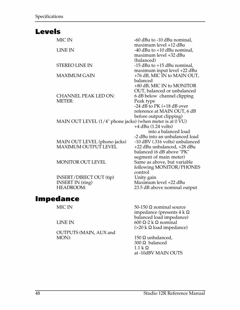
LevelsMIC IN -60 dBu to -10 dBu nominal,
maximum level +12 dBuLINE IN -40 dBu to +10 dBu nominal,
maximum level +32 dBu(balanced)
STEREO LINE IN -15 dBu to +15 dBu nominal,maximum input level +22 dBu
MAXIMUM GAIN +76 dB, MIC IN to MAIN OUT,balanced+80 dB, MIC IN to MONITOROUT, balanced or unbalanced
CHANNEL PEAK LED ON: 6 dB below channel clippingMETER: Peak type
-24 dB to PK (+18 dB overreference at MAIN OUT, 6 dBbefore output clipping)
MAIN OUT LEVEL (1/4" phone jacks) (when meter is at 0 VU)+4 dBu (1.24 volts)
into a balanced load-2 dBu into an unbalanced load
MAIN OUT LEVEL (phono jacks) -10 dBV (.316 volts) unbalancedMAXIMUM OUTPUT LEVEL +22 dBu unbalanced, +28 dBu
balanced (6 dB above "PK"segment of main meter)
MONITOR OUT LEVEL Same as above, but variablefollowing MONITOR/PHONEScontrol
INSERT/DIRECT OUT (tip) Unity gainINSERT IN (ring) Maximum level +22 dBuHEADROOM: 23.5 dB above nominal output
ImpedanceMIC IN 50-150 Ω nominal source
impedance (presents 4 k Ωbalanced load impedance)
LINE IN 600 Ω-2 k Ω nominal(>20 k Ω load impedance)
OUTPUTS (MAIN, AUX andMON): 150 Ω unbalanced,
300 Ω balanced1.1 k Ωat -10dBV MAIN OUTS

Specifications
Studio 12R Reference Manual 49
Noise performance (typical)Measured at MAIN OUT +4 dBu jacks, unbalanced load, 22 Hz to 22 kHz, allchannels panned to center.
MIC IN to INSERT OUT: -128.5 dBu Equivalent InputNoise at maximum gain
Residual output noise (MASTER fader at nominal, channel faders atminimum):
<-88 dBu
12 inputs, faders and trims at unity gain, inputs terminated 150Ω:<-85 dBu unbalanced(+22 dB max unbalanced out =107 dB dynamic range)
Distortion (THD+N)Measured with a 0 dBu signal coming into a MIC IN jack with trim set for a+15 dBu output from the insert jack.At INSERT jack: Better than 0.0010%At MAIN OUT (+21 dBu balanced output level)
Better than 0.0015%Power
U.S.A. model: 120 VAC, 60 Hz, 40 watts powerconsumption maximum
Mounting19" EIA rack mountable, 3 spaces

Specifications
Studio 12R Reference Manual 50
DIMENSIONALDRAWING

Specifications
Studio 12R Reference Manual 51
BLOCK DIAGRAM
CHANNELS 1-8
STEREO LINE CHANNELS 9-10 AND 11-12
STEREO AUX RETURN
PHANTOM POWERTRIM
TRIM
INSERT LOW
LOW
HIGH
HIGH
L/MONO
R
L/MONO
R
AUX 1
AUX 1
AUX 2
RIG
HTLE
FT
RIG
HTLE
FT
TAPE IN-10 dBV
L R
L-R/2-TRACK
PHONES/MONITOR LEVEL
AUX 1
AUX SENDS
AUX 2
LMAIN OUT
-10dBVR
BALANCE
PHONES
MONITOR OUT
MAIN OUT BALANCED
AUX
1
AUX 2
AUX
2
LEFT
RIG
HT
PAN
60mmFADER
60mmFADER
SHELVING
CLIP
CLIP

Specifications
Studio 12R Reference Manual 52
Level diagram

Index
Studio 12R Reference Manual 53
INDEX
ADAT, 18, 22, 34, 39amplifier, 20, 31Aux 1, 17, 20AUX 2, 16, 32AUX SEND, 16, 20balanced, 12, 20cable, 9clipping, 13compressor, 17direct output
using INSERT jack, 18distortion, 28, 31effect, 16EQ, 31Fader, 30feedback, 20, 21gain, 30ground loop, 35
isolating from rack, 8grounding, 6, 7guitars, 12Headphone, 20, 25headroom, 13, 34, 48HIGH, 41Impedance, 10, 48INSERT cables, 22INSERT jack, 17, 24
in 2-mixer system, 24Levels, 13, 28, 48
diagram, 52LINE IN, 12LOW, 41MAIN OUT -10 dBV, 21MAIN OUT BALANCED, 20Master, 30maximum level, 13, 48meter, 34MIC IN, 10, 13Microphone, 10microphone preamps, 22MONITOR OUT, 14, 20, 25mono, 20MSTR/TAPE switch, 14, 21
affects meter, 34noise, 7, 28, 35, 49nominal, 34PA system, 14, 20PEAK, 28, 34
Phantom power, 13PHONES, 25PHONES/MONITOR, 14, 34phonograph, 15post-fader, 32pre-fader, 17rack, 8, 36reverbb, 16Service, 45shield, 36Specifications, 47stage monitor, 20STEREO AUX RETURN, 16, 32STEREO LINE channels
as Effect Return, 16, 32for CDs and synths, 12maximum input level, 13PEAK LED, 28
TAPE IN, 14as Aux 1 monitor, 42
tape recorder, 21TRIM, 9, 13, 22, 28, 29, 30, 39TRS, 17, 20Unity gain, 30wet/dry, 17, 32XLR, 10, 13