Embed Size (px)
Citation preview
Jouni Heinäharju
Home Automation and Transparent Data Transmission Using Single-Medium Network Concept
Thesis submitted in partial fulfillment for the degree of Master of Science
Espoo, July 23, 2009
Supervisor Prof. Jorma Skyttä
Instructor Ph.D. Tapio Marttinen
Home Automation and Transparent Data Transmission Using Single-Medium Network Concept
ii
HELSINKI UNIVERSITY OF TECHNOLOGY
ABSTRACT OF THE MASTER’S THESIS
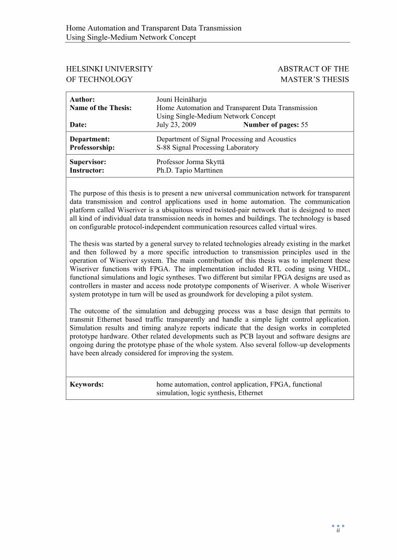
Author: Jouni Heinäharju Name of the Thesis: Home Automation and Transparent Data Transmission Using Single-Medium Network Concept Date: July 23, 2009 Number of pages: 55
Department: Department of Signal Processing and Acoustics Professorship: S-88 Signal Processing Laboratory
Supervisor: Professor Jorma Skyttä Instructor: Ph.D. Tapio Marttinen
The purpose of this thesis is to present a new universal communication network for transparent data transmission and control applications used in home automation. The communication platform called Wiseriver is a ubiquitous wired twisted-pair network that is designed to meet all kind of individual data transmission needs in homes and buildings. The technology is based on configurable protocol-independent communication resources called virtual wires. The thesis was started by a general survey to related technologies already existing in the market and then followed by a more specific introduction to transmission principles used in the operation of Wiseriver system. The main contribution of this thesis was to implement these Wiseriver functions with FPGA. The implementation included RTL coding using VHDL, functional simulations and logic syntheses. Two different but similar FPGA designs are used as controllers in master and access node prototype components of Wiseriver. A whole Wiseriver system prototype in turn will be used as groundwork for developing a pilot system. The outcome of the simulation and debugging process was a base design that permits to transmit Ethernet based traffic transparently and handle a simple light control application. Simulation results and timing analyze reports indicate that the design works in completed prototype hardware. Other related developments such as PCB layout and software designs are ongoing during the prototype phase of the whole system. Also several follow-up developments have been already considered for improving the system.
Keywords: home automation, control application, FPGA, functional simulation, logic synthesis, Ethernet

Home Automation and Transparent Data Transmission Using Single-Medium Network Concept
iii
TEKNILLINEN KORKEAKOULU DIPLOMITYÖN TIIVISTELMÄ
Tekijä: Jouni Heinäharju Työn nimi: Taloautomaatio ja läpinäkyvä datasiirto yleiskäyttöisessä tietoverkossa Päivämäärä: 23.7.2009 Sivumäärä: 55
Osasto: Signaalinkäsittelyn ja akustiikan laitos Professuuri: S-88 Signaalinkäsittelytekniikan laboratorio
Työn valvoja: Professori Jorma Skyttä Työn ohjaaja: FT Tapio Marttinen
Tämän diplomityön tarkoituksena on esitellä uusi yleiskäyttöinen tietoliikenneverkko läpinäkyvää tiedonsiirtoa ja kotiautomaation ohjaussovelluksia varten. Tietoliikennealusta nimeltään Wiseriver on ubiikki (kaikkialla läsnä oleva) langallinen parikaapeliverkko, joka on suunniteltu vastaamaan kaikenlaisiin yksittäisiin tiedonsiirtotarpeisiin kodeissa ja rakennuksissa. Teknologia perustuu konfiguroitaviin protokollariippumattomiin tiedonvälitysresursseihin, joita kutsutaan käsitteellä ”virtual wire” (virtuaalinen johto). Opinnäyte alkoi yleiskatsauksella vastaavanlaisiin jo markkinoilla oleviin teknologioihin, jonka jälkeen seurasi tarkempi perehtyminen Wiseriver-järjestelmän toiminnassa käytettäviin tiedonvälitysperiaatteisiin. Keskeisin osuus opinnäytteen tekemisessä oli näiden Wiseriver-toimintojen implementointi FPGA:lla. Implementaatio sisälsi RTL-koodausta, simulointia ja logiikkasynteesiä. Kaksi erillistä, mutta samankaltaista FPGA-toteutusta toimivat ohjaimina Wiseriverin isäntä- ja liitäntäsolmuyksiköiden prototyyppiversioissa. Kokonainen Wiseriverin järjestelmäprototyyppi puolestaan toimii perustana kehitettäessä järjestelmää edelleen pilottikohteeseen. Simulaatio- ja testaustyön lopputuloksena syntyi perustoteutus, joka kykenee välittämään läpinäkyvästi Ethernet-pohjaista liikennettä ja hallitsemaan yksinkertaista valo-ohjaussovellusta. Simulaatiotulokset ja ajoitusraportit osoittavat että toteutus toimii myös valmisteilla olevassa prototyyppilaitteistossa. Wiseriver-järjestelmän prototyyppivaihe sisältää useita eri tahtiin eteneviä osakokonaisuuksia sisältäen esimerkiksi piirilevy- ja ohjelmistosuunnittelua. Jatkokehitystä ajatellen on myös jo olemassa suunnitelmia järjestelmän laajentamiseksi edelleen.
Avainsanat: kotiautomaatio, ohjaussovellus, FPGA, simulointi, logiikkasynteesi, Ethernet
Home Automation and Transparent Data Transmission Using Single-Medium Network Concept
iv
Preface
This thesis has been written for Wiseriver during the years 2008 and 2009. I am very grateful to my supervisor Prof. Jorma Skyttä and to relevant people from Wiseriver for giving me this opportunity to write this thesis of a fascinating topic.
I would like to thank my instructor Ph. D. Tapio Marttinen for enlightening conversations and helpful guidance during the challenging and instructive process. It has been a rewarding time.
Finally, I would like to take this opportunity to thank my parents for endless economical and mental support throughout my entire studies.
Helsinki, July 23, 2009
Jouni Heinäharju
Home Automation and Transparent Data Transmission Using Single-Medium Network Concept
v
Contents
Preface ............................................................................................................................. iv
Contents ............................................................................................................................ v
Terms and Abbreviations ................................................................................................ vii
1 Introduction ............................................................................................................... 1
1.1 Purpose of Intrabuilding Network ...................................................................... 1
1.2 Properties of Intrabuilding Network .................................................................. 1
2 Available Solutions for Intrabuilding Communication ............................................ 3
2.1 Intelligent House Control (IHC) ........................................................................ 3
2.1.1 Basic Principle ............................................................................................ 3
2.1.2 Units ............................................................................................................ 4
2.1.3 Programming .............................................................................................. 4
2.2 Light Control Network (Linet) ........................................................................... 5
2.2.1 General Information .................................................................................... 5
2.2.2 Nodes, Controller and Technology ............................................................. 5
2.3 LonWorks (LON) ............................................................................................... 6
2.3.1 Overview of the Network Platform ............................................................ 6
2.3.2 Network Devices and Neuron Chip ............................................................ 7
2.3.3 LonWorks Protocol ..................................................................................... 8
2.4 Konnex (KNX) ................................................................................................... 9
2.4.1 Technology Overview ................................................................................. 9
2.4.2 Communication Protocol .......................................................................... 10
2.4.3 Application and Interworking Models ...................................................... 11
2.4.4 Configuration Profiles ............................................................................... 12
2.5 Wireless Systems ............................................................................................. 12
2.5.1 ZigBee ....................................................................................................... 12
2.5.2 Z-Wave ..................................................................................................... 13
2.6 Digital Living Network Alliance (DLNA) ....................................................... 14
2.7 Integration Platforms ........................................................................................ 15
2.7.1 Nokia Home Control Center (NHCC) ...................................................... 16
2.7.2 open Source Service Gateway (oSSG) ..................................................... 16
2.8 Summary .......................................................................................................... 17
Home Automation and Transparent Data Transmission Using Single-Medium Network Concept
vi
3 Wiseriver Platform and Components ...................................................................... 19
3.1 General Overview ............................................................................................ 19
3.2 Architecture, Topology and Transmission Modes ........................................... 19
3.3 Principle of Transparent Data Transmission .................................................... 21
3.4 Management of Network and Control Applications ........................................ 22
3.5 Mechanical Implementation of Components ................................................... 23
3.6 Comparison and Summary of Wiseriver Features ........................................... 24
4 Implementation of Wiseriver Functions with FPGA .............................................. 26
4.1 Lower-Level-Ring Controller (LLRC) ............................................................ 26
4.2 Access Node Controller (ANC) ....................................................................... 27
4.3 Polling Protocol and Control Application Interfaces ....................................... 28
4.3.1 1-Wire ....................................................................................................... 30
4.3.2 Inter-Integrated Circuit (I2C) .................................................................... 31
4.4 ETH PHY Interface .......................................................................................... 33
4.4.1 CSMA/CD and Duplex ............................................................................. 33
4.4.2 PHY Transceiver and Media Independent Interface ................................. 33
4.4.3 Data Flow Control .................................................................................... 34
4.4.4 Management Data Input/Output (MDIO) ................................................. 36
4.5 External Buffer Interface .................................................................................. 36
4.6 Nios II Embedded Soft Core Microprocessor .................................................. 37
4.6.1 Memory Subsystem .................................................................................. 38
4.6.2 System Interconnection Fabric (Avalon) .................................................. 39
4.6.3 Universal Serial Bus (USB) ...................................................................... 40
5 Wiseriver Prototype ................................................................................................ 41
5.1 Functional Simulation ...................................................................................... 41
5.2 Synthesis for FPGA Design ............................................................................. 42
5.2.1 Nios II Integration ..................................................................................... 43
5.3 Verification in Hardware .................................................................................. 45
6 Conclusions and Future Work ................................................................................ 47
References ....................................................................................................................... 49
Appendix ......................................................................................................................... 51

Home Automation and Transparent Data Transmission Using Single-Medium Network Concept
vii
Terms and Abbreviations
100BASE-TX 100 Mbit/s, baseband, twisted pair based Ethernet standard 8P8C 8 Position 8 Contact connector
A/D Analog-to-digital AAC Advanced Audio Coding AES Advanced Encryption Standard ANC Access Node Controller ANSI American National Standards Institute AV Audio/Video
BACnet Building Automation and Control networks
CAD Computer-Aided Design CE Consumer Electronics CSMA/CD Carrier Sense Multiple Access with Collision Detection
D/A Digital-to-analog DHCP Dynamic Host Configuration Protocol DLNA Digital Living Network Alliance DNS Domain Name System DPRAM Dual-Port RAM DSL Digital Subscriber Line DTV Digital Television DVR Digital Video Recorder
EEPROM Electronically Erasable Programmable ROM EIB European Installation Bus ETH Ethernet ETS Engineering Tool Software
FIFO First In, First Out FPGA Field-Programmable Gate Array FSM Finite State Machine
GSM Global System for Mobile communications GUI Graphical User Interface
HTTP Hypertext Transfer Protocol HVAC Heating, Ventilating and Air Conditioning
I/O Input/Output I2C Inter-Integrated Circuit IC Integrated Circuit IEC International Electrotechnical Commission
Home Automation and Transparent Data Transmission Using Single-Medium Network Concept
viii
IEEE Institute of Electrical and Electronics Engineers IF Interface IHC Intelligent House Control IP Internet Protocol or Intellectual Property IPTV IP Television IR Infrared ISO International Organization for Standardization
JTAG Joint Test Action Group
KNX Konnex
LAN Local Area Network LED Light-Emitting Diode LLRC Lower-Level-Ring Controller LNS LonWorks Network Services LON Local Operating Network LPCM Linear Pulse Code Modulation LSB Least Significant Bit
MAC Media Access Control MDIO Management Data Input/Output MDIX Medium Dependent Interface crossover MII Media Independent Interface MP3 MPEG-1 Audio Layer III MPEG Moving Picture Experts Group MSB Most Significant Bit
NAS Network-Attached Storage NHCC Nokia Home Control Center
oBIX Open Building Information Exchange OEM Original Equipment Manufacturer OHCI Open Host Controller Interface OSI Open Systems Interconnection OS Operating System oSSG open Source Service Gateway
P2P peer-to-peer or point-to-point PC Personal Computer PCB Printed Circuit Board PDA Personal Digital Assistant PHY Physical layer PLL Phase-Locked Loop PoE Power over Ethernet
Home Automation and Transparent Data Transmission Using Single-Medium Network Concept
ix
RAM Random-Access Memory RF Radio Frequency RISC Reduced Instruction Set Computer RJ-45 Registered Jack RMII Reduced MII ROM Read-Only Memory RS-232 Recommended Standard 232 RTL Register Transfer Level
SDRAM Synchronous Dynamic RAM SMII Serial MII SMS Short Message Service SMT Surface-Mounted Technology SOPC System on a Programmable Chip S/PDIF Sony/Philips Digital Interconnection Format SRAM Static RAM
UART Universal Asynchronous Receiver/Transmitter UPnP Universal Plug and Play USB Universal Serial Bus UTP Unshielded Twisted Pair
VHDL VHSIC Hardware Description Language VHSIC Very High Speed IC
WLAN Wireless LAN WWW World Wide Web
XML Extensible Markup Language
Home Automation and Transparent Data Transmission Using Single-Medium Network Concept
1
1 Introduction
1.1 Purpose of Intrabuilding Network A certain kind of network connecting different equipments is needed for a comprehensive automation and data transmission in a house. Different degrees of automation or intelligence can be seen in intrabuilding networks. Maximum control is achieved when all activity is integrated in one comprehensive communication system with access points to external internet or mobile lines.
Possible sub-systems to be connected are
• lighting • HVAC • security, surveillance & alarming • multimedia entertainment and AV networks • computer data network
Lighting systems can be used for automated scenarios of illumination whereas HVAC includes temperature and humidity control according to room usage. Security systems consist of sensors, detectors and alarms to report faults, burglaries or fires. Timers can be used to simulate occupied home to prevent potential intrusions. Entertainment and communication functions allow distribution of audio and video signals to multiple locations. All these applications are linked together with a control system. [1]
However, everything cannot and perhaps even should not be automated. A control device is not able, for example, to detect when certain food ingredient is cooked enough. Human consideration is still needed to estimate the cooking time. The needs of present and future house occupants are satisfied with communication and control network that has flexible functionality and appropriate architectural design. Economical cost and high comfort to user is also desirable. [2]
Basic goals of control systems and data transmission services to occupants on premises could be
• comfort and convenience • time and energy saving • safety and security • ubiquitous data communication • entertainment electronic system
1.2 Properties of Intrabuilding Network As suggested above and by the name of this thesis a functionality of intrabuilding networks is divided to control services and data transmission. These two purposes require somewhat different technological concepts. The control network is used to

Home Automation and Transparent Data Transmission Using Single-Medium Network Concept
2
govern all electrical systems in the house. The purpose of data communication is to transmit information between computers and other peripheral devices.
Control or automation nets such as IHC, LON, KNX, Linet, ZigBee and Z-Wave are used to interconnect sensors and actuators. Sensors include for example buttons, switches, thermometers, smoke detectors, moisture detectors and presence detectors. Examples of actuators are dimmers, relays, valves, sirens and buzzers. These devices are connected at a field level to the network I/Os. Interface could be a customized field level connection or a universal connection like 1-Wire, I2C or even USB. Control networks include mechanisms to create advanced automation systems from these interconnections.
Data and multimedia nets in houses are usually standard Ethernet† and WLAN†† networks including upper level protocols such as DHCP and DNS. Typical data and multimedia devices are PCs, PDAs, DTVs, DVRs, home theaters and game consoles. Web cameras could be used for both surveillance and communication purposes. New DLNA and UPnP guidelines have emerged to generalize data extraction and content interchange techniques.
Most of these available intrabuilding communication solutions mentioned above are discussed and compared in this thesis. The review is followed by presentation, partial prototype implementation and some hardware verification considerations of a whole new Wiseriver platform that includes both home automation and data transmission functionality. Following phases below, not necessarily in presented order, could be completed when creating good house control and data transmission services.
• Definition of functional specification • Selection of system architecture • Programming of controllers • User interface configuration • Installation and start up
Specifications of functionalities and architecture of Wiseriver system were already made but they were refined during the thesis work. Practical section of this thesis concentrates mainly on implementation of the controller functions.
† IEEE 802.3 †† IEEE 802.11
Home Automation and Transparent Data Transmission Using Single-Medium Network Concept
3
2 Available Solutions for Intrabuilding Communication
Many systems exist using various kinds of technologies and communication media. Furthermore, some systems are full monolithic platforms while others just physical layers. Advanced systems are able to provide services at higher application levels and not just at lower data and link levels. Architecturally a traditional approach would be a hierarchical design where every device is connected to a central controller. More recent trend in the industry is to move towards distributed open networks. There have been also aims to integrate these existing systems into a one universal system. This could be achieved using gateways to intermediate the communication of devices from different kinds of networks.
At first in this chapter two examples of centralized systems are discussed. Next a treatment is given to a pair of distributed systems and to a couple of wireless solutions. Finally an attention is paid on related gateway projects after reviewing an attempt to unify digital devices in homes. The emphasis is mainly on most commercial wired systems and a little less on wireless and integration systems. Power line systems such as X10, INSTEON or HomePlug have left out of the scope of this thesis but some of the systems discussed can use also power line as a communication medium.
2.1 Intelligent House Control (IHC)
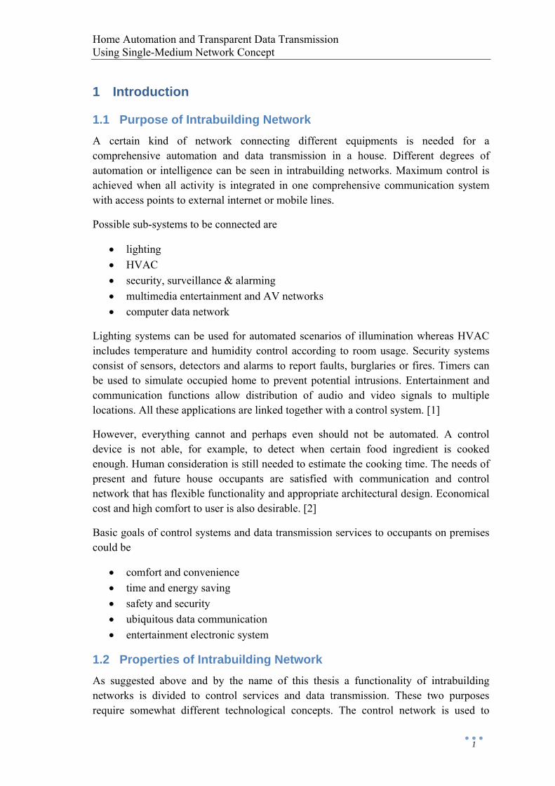
2.1.1 Basic Principle IHC, also known as Strömfors IHC or Schneider IHC, is principally a network of input and output units connected to a central controller. Different kinds of units are available for different purposes and when connected to controller they form a network that has a star topology. Primarily IHC is intended for on/off relay type controls and it is not able to transmit for example direct temperature information. Inputs are used for buttons and sensors, outputs for light and device control through relays. It is stated by manufactures that IHC is the most popular system of its kind in Nordic countries.
Figure 1: Principle of IHC system. Controller has 8 input ports and 16 output ports. Interface addresses are also shown.
Controller
12...8
12...
16
InputUnit
1
1.011.02
1.16
…
InputUnit
8
8.018.02
8.16
…
OutputUnit
1
1.011.02
1.08
…
ProgramInput
Input
Output

Home Automation and Transparent Data Transmission Using Single-Medium Network Concept
4
Unique address is determined for each on/off interface and maximum number of interfaces for a single unit is 16. Also the controller has limited number of ports for input and output units resulting to a total capacity of 128 input addresses and 128 output addresses for a single controller. It is possible to chain or link several controllers together to form a larger network. [3]
2.1.2 Units Input and output units are available of few different types from which the choice is made by the required voltage. 24 V output units are used typically for LED indicators, light regulators or other low-voltage equipments. 230 V and 400 V units are utilized for bigger loads. Most common input unit is of type 24 V and it is used for push buttons, keypads and security sensors. Cabling is done with combination of control cables and UTP cables.
In addition to push buttons and relays there is a wide variety of other components that complement the functionality of the basic units. These products include light regulators, temperature controllers, IR sensors and remote controllers for achieving a more complete control. Universal light regulators have different operation modes and memory locations for used light levels. This feature is useful for example in nightlights and other lighting schemes.
Considering remote control, an interesting device called a robot phone is available. It is a voice modem that contains spoken messages and its use is based on speech menus. A network device makes remote control possible also from WWW browser. User interface is made based on blueprints saved in JPEG format. The software for this purpose is shipped with the device.
IHC is available as a complete system called ELIT IHC. The package is equipped with most common units and functions to ease the planning and installation of the system. Individual components are available also separately. [4]
2.1.3 Programming Programming of the IHC controller is done with included IHC Win software. Also firmware of the controller is upgradable which allows utilization of newly developed properties. The programming is object oriented with several ready-made object libraries. A beginner can use programs found in these libraries and hence does not necessarily have to learn actual IHC programming. Previous knowledge of any other programming language is not required.
Combining several basic operations it is possible to form more complicated control features. For instance a short push of a button may be given a different meaning than a longer press. IHC has also clock and calendar functions that may be utilized to create more complex activity. Program is transferred to controller with RS-232 cable and it remains in memory during power outages. IHC Win software also includes some simulation, debugging and documentation features.
Home Automation and Transparent Data Transmission Using Single-Medium Network Concept
5
2.2 Light Control Network (Linet)
2.2.1 General Information Linet is positioned between fully wired centralized systems and advanced bus systems. It offers control unit, communication connections and essential basic functions while having the ease of installation of the bus approach. The network is intended for controlling simple devices in small applications.
The network can have up to 200 nodes and one control unit in any topology. Connecting control units together it is possible to form a larger network. Light twisted pair cabling is used to transmit information between nodes and the control unit. Linet software offers a set of functions for on/off control information, data transmission and A/D conversion to implement specific applications. Network nodes are configured to groups and only one function is active in any group. If a system is completed using just basic functions then there is no need to write software.
An example of industrial application is a set of temperature sensors attached to nodes’ A/D converters. Collected data is used for a furnace control that adjusts heating elements connected to another set of nodes. In a home automation example a node could be attached to a light switch. The network will carry the on/off signal from the switch to a relay that controls a lamp. A tenant can use the control unit to arrange any switch to control any lamp without re-cabling. [5]
2.2.2 Nodes, Controller and Technology The node is a SMT packaged IC requiring network components and application specific circuitry to link simple devices into the network. Placing a microcontroller next to a node enables development of applications that demand distributed intelligence.
Linet controller provides communication and configuration services and also supplies power for nodes in the network. The controller is shipped with software that runs on RISC processor. Extensions are possible to develop by obtaining the firmware source code. Network administration is done using terminal application and the user interface can be disconnected after the configuration. The controller operates stand-alone or forms an Ethernet link to a host system for remote accessibility. [6]
Home Automation and Transparent Data Transmission Using Single-Medium Network Concept
6
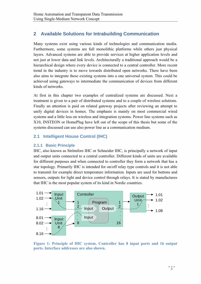
Figure 2: The carrier. Dashed line shows the area that is measured to detect the signal.
Linet network operates using time division protocol. Data and power are distributed to separate half-waves of 20 kHz sinusoidal signal as shown in figure above. Carrier frame is 253 bits long and each node has a time slot of its own and can transmit and receive 80 bits/s all the time. Synchronization and service bits are included in the beginning of the frame. Protocol and interface logic is written in the node IC’s EEPROM memory. [7]
2.3 LonWorks (LON)
2.3.1 Overview of the Network Platform LonWorks, or just LON, is a network platform originally created by Echelon as a generic and competitive solution to the problem of control systems. Because there are certain difficulties to install and maintain central controllers, LonWorks technology is a step away from proprietary centralized systems towards open distributed systems. Common infrastructure also prevents isolation of separate control systems. Manufacturers have a possibility to build products using off-the-shelf chips and operating systems providing improved interoperability and flexibility. Echelon itself manufactures dozens of LonWorks products with technical support and training.
Interoperability of the system is advertised as an ability to integrate products from multiple vendors. In practice, the interoperability is approached by standardizing the protocol, incorporating data and object profiles into the programming model and managing the evolution of standard conforming product certifications and interoperability guidelines. [8]
A LonWorks based control network can range in size and complexity. A network including up to 32 385 devices can be used for wide variety of applications in homes, supermarkets and skyscrapers. Nodes on the network are not just dumb I/O devices but have enough intelligence to communicate directly to each other without the need of a central controller. Communication among the nodes permits the distribution of processing loads and implementation of control functions.
A flat P2P architecture is the choice for a control device to communicate freely and efficiently with every other device on the network. The architecture is similar in some
0 V
+20 V
-20 V
power power
’0’ ’1’
Home Automation and Transparent Data Transmission Using Single-Medium Network Concept
7
ways as the architecture of the Internet where supervisory controller is not required to poll devices for information and then retransmit that to other devices. Software of the LonWorks requires a network database component to maintain and manage the open control system.
LonWorks is configured with LNS operating system that runs on a server. OS is not required for communication between devices during the normal operation since it just provides installation and maintenance services along with network tools. Users design a system with CAD-like environment, commit the installation to devices and generate documentation. Legacy I/O interfaces can be integrated to the system with suitable gateways.
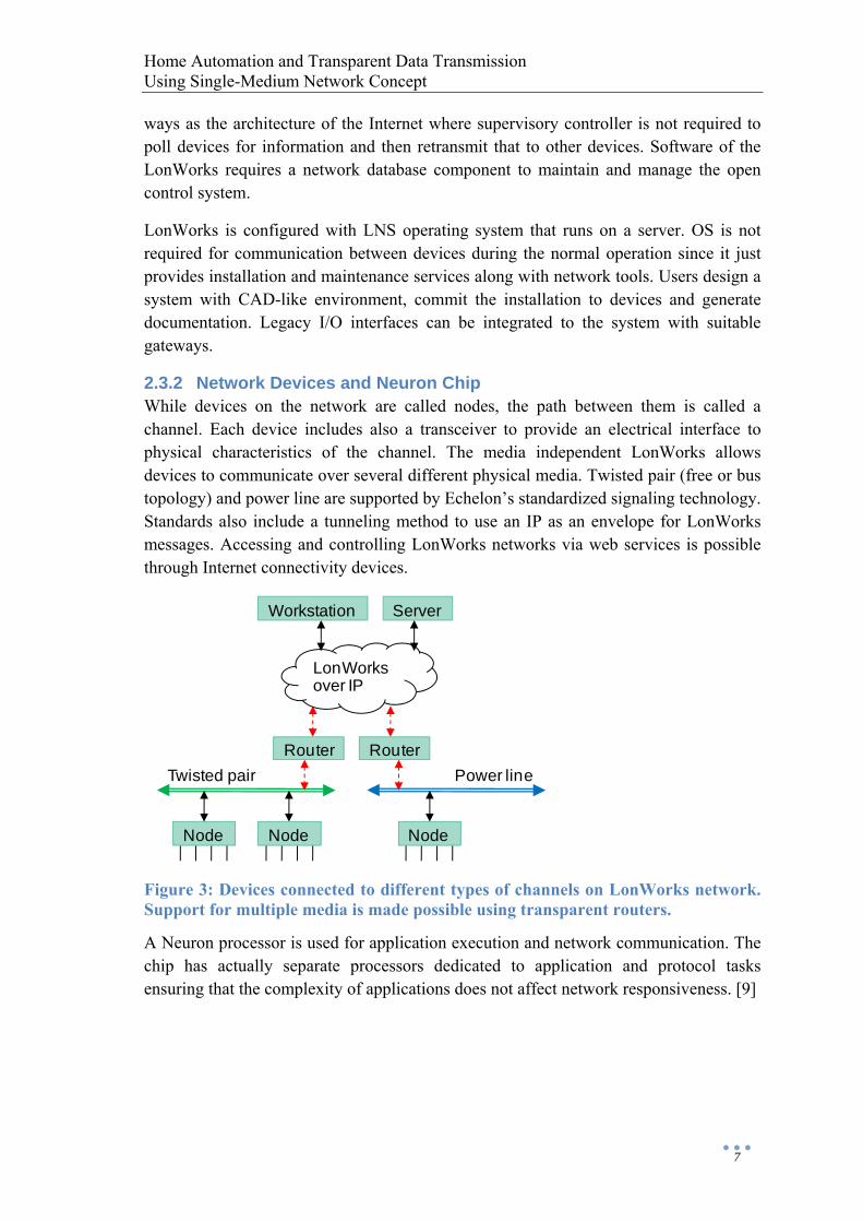
2.3.2 Network Devices and Neuron Chip While devices on the network are called nodes, the path between them is called a channel. Each device includes also a transceiver to provide an electrical interface to physical characteristics of the channel. The media independent LonWorks allows devices to communicate over several different physical media. Twisted pair (free or bus topology) and power line are supported by Echelon’s standardized signaling technology. Standards also include a tunneling method to use an IP as an envelope for LonWorks messages. Accessing and controlling LonWorks networks via web services is possible through Internet connectivity devices.
Figure 3: Devices connected to different types of channels on LonWorks network. Support for multiple media is made possible using transparent routers.
A Neuron processor is used for application execution and network communication. The chip has actually separate processors dedicated to application and protocol tasks ensuring that the complexity of applications does not affect network responsiveness. [9]
LonWorksover IP
Power lineTwisted pair
NodeNode Node
Workstation Server
Router Router
Home Automation and Transparent Data Transmission Using Single-Medium Network Concept
8
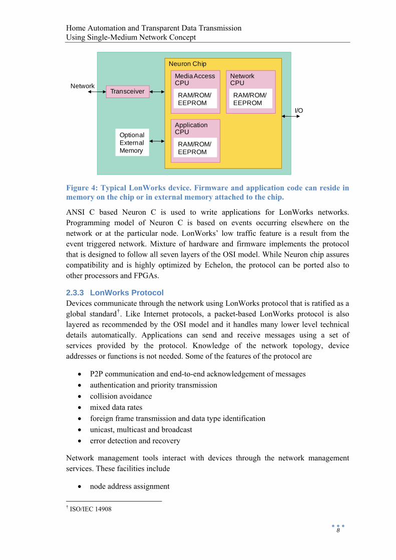
Figure 4: Typical LonWorks device. Firmware and application code can reside in memory on the chip or in external memory attached to the chip.
ANSI C based Neuron C is used to write applications for LonWorks networks. Programming model of Neuron C is based on events occurring elsewhere on the network or at the particular node. LonWorks’ low traffic feature is a result from the event triggered network. Mixture of hardware and firmware implements the protocol that is designed to follow all seven layers of the OSI model. While Neuron chip assures compatibility and is highly optimized by Echelon, the protocol can be ported also to other processors and FPGAs.
2.3.3 LonWorks Protocol Devices communicate through the network using LonWorks protocol that is ratified as a global standard†. Like Internet protocols, a packet-based LonWorks protocol is also layered as recommended by the OSI model and it handles many lower level technical details automatically. Applications can send and receive messages using a set of services provided by the protocol. Knowledge of the network topology, device addresses or functions is not needed. Some of the features of the protocol are
• P2P communication and end-to-end acknowledgement of messages • authentication and priority transmission • collision avoidance • mixed data rates • foreign frame transmission and data type identification • unicast, multicast and broadcast • error detection and recovery
Network management tools interact with devices through the network management services. These facilities include
• node address assignment
† ISO/IEC 14908
Neuron Chip
Media AccessCPU
Transceiver RAM/ROM/EEPROM
NetworkCPU
RAM/ROM/EEPROM
ApplicationCPU
RAM/ROM/EEPROM
OptionalExternalMemory
Network
I/O
Home Automation and Transparent Data Transmission Using Single-Medium Network Concept
9
• multicast group specification • network traffic monitoring • node/network diagnostics • application code downloading
The Ethernet MAC algorithm is not well suited to control applications because it performs poorly under overload. To meet requirements during heavy loads, LonWorks uses predictive CSMA protocol that allows a channel to operate at full capacity without a lot of collisions. A specific feature is various levels of delays called Beta 2 slots that are dynamically adjusted to every device based on expected network load.
Routing of packets from a source device to destination devices is defined by addressing algorithm that support physical, device, group and broadcast address types. More than one independent LonWorks systems are able to coexist on the same physical channel. In addition to several messaging services, LonWorks offers also authentication service by 48-bit keys. This allows receivers to determine if the sender is authorized to send a message.
Yet another concept is network variables. These are particular data items that a device expects to get from other devices on the network. When the variable is received the firmware of the device passes the value to the application program. Network variables are configured during network design and installation. This process creates logical connections between certain type of output and input variables and these connections may be thought of as “virtual wires”. Difference compared to the centralized system in Figure 1 is that input, output and program can now reside in any unit. A simple example of the connection is again a light bulb as an output and a switch as an input. It is more difficult to design interoperable devices to older type command-based systems than to information-based systems where the device collects information by its own about what is going on in the system. [10]
2.4 Konnex (KNX)
2.4.1 Technology Overview Basic idea of KNX is fundamental as purpose is to combine all building’s electrical systems to a single efficient network. KNX bus technology is intended for applications such as lighting, HVAC, security, energy management and blinds/awning control. KNX automation is suitable for new as well as existing houses and buildings of different size. Global open KNX standard† is administered by KNX Association and technology is based on several predecessor systems developed in early 1990s. Common application-independent bus solution is desired to overcome some problems of isolated devices in proprietary solutions. [11]
All control information transmitted to the bus is available everywhere in the system. Certified interoperable devices from several manufacturers can be freely added to the † ISO/IEC 14543

Home Automation and Transparent Data Transmission Using Single-Medium Network Concept
10
bus and they are compatible to communicate themselves without a central controller. Also gateways to other protocols and management-level systems are available. Cabling reinstallations are avoided because logical functionality is defined by programming. Power supply is separated from control cables to simplify installation. Commissioning of the system is designed efficiently with ETS. Access to the system is possible by touch panels or remotely through phone, SMS, LAN or Internet. [12]
KNX technology can be implemented on any processor platform either from scratch or with help of available OEM system modules like coupling units and chip sets. All products undergo a strict certification process at neutral laboratories to receive KNX compliance trademark. Product quality is ensured when the device
• can interpret signals on the medium as specified • is configurable by manufacture independent ETS • realizes specified interworking functions and data types
KNX specifies many essential mechanisms for manufactures to utilize
• communication messages and protocol stack for all communication requirements
• application and interworking models for various tasks • network configuration and management schemes for linking distributed
applications that run in different nodes • device profiles for actual devices
2.4.2 Communication Protocol KNX supports several communication media. Twisted pair, power line and RF each have a slightly different bitrates but all these media implement CSMA mechanism. In IP communications LAN or Internet is used to tunnel KNX telegrams.
Logical node architecture is realized in devices connected to the bus. Device models and resources vary according to node capabilities. Devices are identified and accessed by their addresses.
Home Automation and Transparent Data Transmission Using Single-Medium Network Concept
11
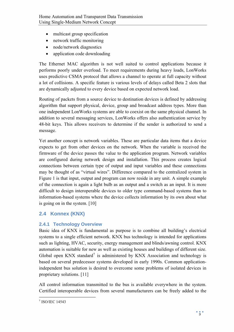
Figure 5: The logical architecture of KNX. Couplers connect lines using bridge or router functionality.
KNX communication system is compliant to a 7 layer OSI model. Example format in table below corresponds to the interface above layer 2.
Table 1: Standard KNX frame structure, some preamble may be defined.
Octet 0 1..2 3..4 5 6 7 8..N - 1 N ≤ 22 Control Field
Source Address
DestinationAddress
Address Type
TPCI APCI Data Frame Check
2.4.3 Application and Interworking Models Central concept is the data points that represent the process and control variables. Data points may be inputs, outputs, parameters or other data containers. Elements modeled as data points shall be understood as a network interface. Communication system and protocol offers an instruction set to read and write data point variables that are accessed through unicast or multicast mechanisms.
A device sends a write message when a local application writes a value to a sending data point. A receiving data point with corresponding address receives the value and its local application can now act upon this updated value. The action can be a state change, another write message or a physical output modification. Polling and call back implementations are supported by the communication stack. Local applications with linked data points form a distributed application. Address binding principles are used to establish these links.
KNX have a core set of data types to ensure interworking in multivendor networks. Interworking requires also some discovery procedures to provide essential information
Area 15
1.15.000Area 2
1.15.000
15.0.000
2.0.000
Area 1
1.1.001
…
…
1.1.000
Main line 1.0
1.1.002
1.15.255
1.2.001
…1.2.000
1.2.002
1.15.255
1.15.001
1.15.000
1.15.002
1.15.255
…
1.0.000
Coupler
Node
Home Automation and Transparent Data Transmission Using Single-Medium Network Concept
12
about devices on the KNX network. So called KNX profiles implement a set of descriptor fields and objects that KNX configuration masters look for to manage the network. [13]
2.4.4 Configuration Profiles KNX supports System and Easy configuration modes. The difference between two modes is that S-Mode offers more flexibility with versatile configuration options whereas in E-Mode components are pre-configured to default parameters thus having more limited functionality.
Configuration features such as address binding, device parameterization and application program downloading are defined during installation. The system can be designed offline in a graphical way and download the result when components are mounted. The offline representation is a system database containing metadata of the installation. Network management in KNX identifies the different network resources within the devices in order to enable a proper interworking. Detailed descriptions of the resources, device models and other features are specified in the relevant profiles. Network management toolkit can be used for initial setup, integration of multi-mode installations, diagnostics and maintenance. [14]
2.5 Wireless Systems
2.5.1 ZigBee ZigBee is a standards-based† protocol that defines network and application layers and provides infrastructure for wireless sensors. Home automation is one of the typical applications of ZigBee. Low cost, reliability, low power and easy deployment are some of the technological motivations. Evolution of the standard is maintained by ZigBee Alliance. Compatible networking capabilities can be included into products using RF modules. Hardware and software solutions are available for embedding RF into typical designs. Products are tested in certification program to ensure compatibility with the standards.
The protocol stack has several layers performing specific services for applications, devices, management, security, networking, MAC and PHY. These services provide
• standard data types and descriptions how to build a profiles onto the stack • control for application objects and endpoints in nodes • messages for requesting access and security • encryption • address handling and routing • reliable communication • interface to physical transmission medium
† Physical and MAC layers are defined by IEEE 802.15.4
Home Automation and Transparent Data Transmission Using Single-Medium Network Concept
13
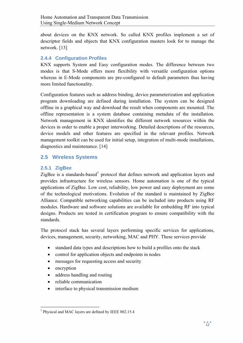
ZigBee is capable of supporting over 64 000 nodes per network and multiple networks can be linked together. Coordinators, routers and end devices are the three device types included in the networks. A coordinator device controls the network and stores information about security keys. Routers extend network area coverage whereas end devices transmit or receive messages. End devices are interconnected through P2P mesh network that contains multiple routers and a single controller. MAC association is the bare-bones default to join network.
Figure 6: ZigBee mesh network.
Mesh network topology supports multi-hop communication for reliability and robustness. Routers are typically connected through at least two pathways. Each router maintains a routing table where routes are established on-demand using a route discovery process.
Collection of devices employed for specific application is described by an application profile. Such application profile is defined also for home automation. Devices within an application profile communicate in clusters using specified messaging scheme. Connections between two endpoints with a specific application profile are called bindings.
Commissioning of the primary network is performed by the installer using intuitive commissioning tools running on a laptop or PDA. ZigBee security is based on a 128-bit AES algorithm and whether to allow or disallow new devices into the network is usually decided by the controller. [36]
2.5.2 Z-Wave Z-Wave protocol is a wireless RF-based communications technology designed by Zensys for control and status reading applications in residential and light commercial environments. A low-cost reliable wireless networking is delivered by substituting hardware with software solutions and focusing on narrow bandwidth applications such as on-off commands. Devices can be transformed into intelligent network nodes that can be controlled and monitored wirelessly. Remote control applications of Z-Wave include for instance lighting, HVAC and security.
Coordinator
Router
End device
Data flow
Virtual link
Home Automation and Transparent Data Transmission Using Single-Medium Network Concept
14
The technology is available as single chip solutions that include radio transceiver, microprocessor, system interfaces and flash memory including embedded protocol stack and application software. Manufacturing blueprints of the PCB circuitry around the chip including antennas and filters are also offered. Z-Wave designs can be licensed and certified to ensure interoperability between all products. [37]
Z-Wave is an intelligent distributed mesh networking technology that has no master unit. Messages are automatically routed around household obstacles and radio dead spots in the network. Z-Wave can consist of up to 232 devices per network with the option of bridging multiple networks via gateways. Each device is identified by an individual code selected from more than 4 billion options. Devices on the network can be programmed to work singly or in groups where multiple devices are triggered by certain events
Devices are added to the network by inclusion process. Usually this is achieved by pairing a controller with the controllable device being added to the system.
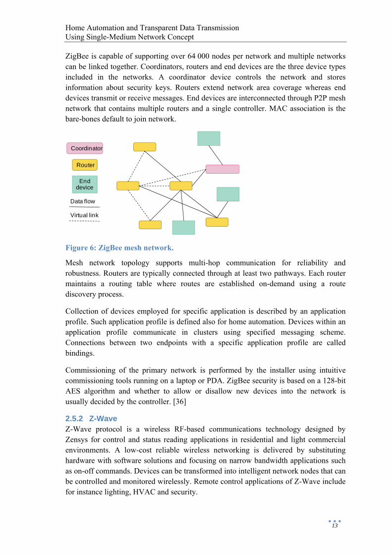
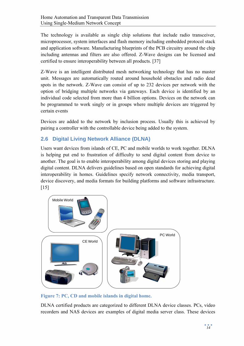
2.6 Digital Living Network Alliance (DLNA) Users want devices from islands of CE, PC and mobile worlds to work together. DLNA is helping put end to frustration of difficulty to send digital content from device to another. The goal is to enable interoperability among digital devices storing and playing digital content. DLNA delivers guidelines based on open standards for achieving digital interoperability in homes. Guidelines specify network connectivity, media transport, device discovery, and media formats for building platforms and software infrastructure. [15]
Figure 7: PC, CD and mobile islands in digital home.
DLNA certified products are categorized to different DLNA device classes. PCs, video recorders and NAS devices are examples of digital media server class. These devices
PC World
Mobile World
CE World

Home Automation and Transparent Data Transmission Using Single-Medium Network Concept
15
store content and make it available to the network. Digital media controllers, e.g. PDAs, find content on servers and play it on digital media renderers, e.g. TVs. Digital media players are able to play media directly from servers. There are separate classes also for corresponding mobile devices, uploaders, downloaders, printers and infrastructure devices. Compatibility is tested through certification means. The certificate ensures that a device conforms to rigorous guidelines and has proven compatible.
Foundation for networking and interoperability in DLNA is IP protocol. It allows applications communicate transparently over wired and wireless media. UPnP technology enables to discover presence and capabilities of the devices based on DLNA guidelines. IP addresses along with other network properties are configured automatically.
DLNA supervises UPnP AV grouping within the UPnP standards. UPnP AV technology addresses content management and control needs to identify and distribute media content across the network. Specifications define architecture and interaction model between devices to allow content in any format over any transfer protocol. UPnP AV specifications define also services to
• enumerate the available content, e.g. videos, music, pictures • determine how the content can be transferred • control the flow of the content, e.g. pause, seek • control how the content is played, e.g. volume, brightness
Media format model defines a set of media formats to content that passes over the network. LPCM is reasonable choice for audio format in wired environments. Compressed audio formats such as MP3 and AAC are more efficient for wireless devices. MPEG-2 and MPEG-4 are corresponding formats for video. [16]
2.7 Integration Platforms For communication between systems there is a standard called BACnet that includes mechanisms for information exchange. BACnet however is not discussed in further detail here. More recent solutions are NHCC and oSSG integration platforms which are based on a gateway. As already mentioned earlier a gateway could be used to allow access to legacy protocol networks. Gateways of NHCC and oSSG operate on a system level to intermediate the communication of devices from different kinds of networks
Generally the term residential gateway is used to describe home routers and modems. These devices allow connection of a LAN to an external network like Internet. The connection is usually provided through DSL, cable modem or mobile broadband network. Residential gateways are gaining capabilities of corporate gateways and may provide functions suitable also for remote house control. Some of commercial residential gateways use Linux-based firmware which requires manufacturers to publish the source code. This allows third parties to modify and change the code and thus
Home Automation and Transparent Data Transmission Using Single-Medium Network Concept
16
enhance original features and performance. One such firmware project is OpenWrt that has expanded to support chipsets from several manufacturers.
2.7.1 Nokia Home Control Center (NHCC) NHCC is an open Linux based platform for creating intelligent homes that are controlled using unified user interface. The platform supports most common technologies and it can be controlled with a mobile phone and web browser. Third parties are allowed to develop their own solutions on top of the framework and expand the system with new technologies. NHCC acts as a dictionary that translates different technological languages from different manufactures presented under the user interface. The platform relies on a partner program that offers full documentation, a library of control functions and development support for third parties. [17]
NHCC is built on top of standard gateway architecture including
• antennas for WLAN, GSM and Z-Wave • connectors for USB and Ethernet • CPU, RAM and internal storage • flash card reader
Embedded open Linux firmware offers possibilities to build server functionalities for web, email and file sharing. Graphical user interface is provided for browser and mobile devices to control home appliances. Control functionality includes
• logic for simple automatic responses and events for sensor triggering, luminance levels and temperature limits
• grouping of devices for easy control • profile support for home, away, day and night setups • linking of different systems
2.7.2 open Source Service Gateway (oSSG) oSSG is free open source based software implementing oBIX interface which can be utilized to develop house control functions. The platform permits integration of separate technical devices and systems in a building. Electrical building services center STOK develops the software at integration laboratory that is open for research and educational purposes. [18]
So far practical implementation of oSSG has been studied with prototype server. The idea is to integrate management of automation systems using standard way to describe data and communication. Thus the question is of generally usable oBIX enabled equipment server for automation systems. oBIX has been chosen as data storing and transmission format between user interface and devices. Adapters are used to connect devices to the server by translating different protocols to standard oBIX format. The standalone server works with Windows and Linux operating systems and is independent of any specific hardware. [19]
Home Automation and Transparent Data Transmission Using Single-Medium Network Concept
17
oBIX defines web services based mechanisms for control systems. The standard is being developed under OASIS consortium in parallel with an open source Java toolkit for working with oBIX. Access to embedded control systems is the main purpose that oBIX is designed for. [20]
The groundwork for building machine-to-machine communication is laid using standard XML and HTTP network technologies. Common XML syntax is used to represent information of diverse systems as extensible object models that are called contracts. An object that uses a contract as a template or a prototype is said to be an implementation of that contract. In object-oriented terminology equivalent concepts would be a class and an instance. Objects and their state are accessed using HTTP GET, PUT and POST representational state transfer methods. [21]
oBIX system architecture is based on client-server network model. Server accepts incoming requests through a socket. oBIX does not prevent software from being both an server and a client. oSSG server includes client side functions to minimize possible overhead network traffic caused by polling of rapidly changing real-time information.
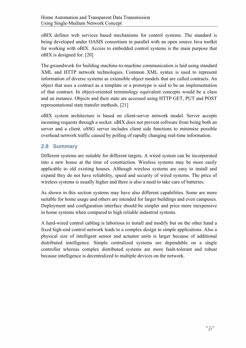
2.8 Summary Different systems are suitable for different targets. A wired system can be incorporated into a new house at the time of construction. Wireless systems may be more easily applicable to old existing houses. Although wireless systems are easy to install and expand they do not have reliability, speed and security of wired systems. The price of wireless systems is usually higher and there is also a need to take care of batteries.
As shown in this section systems may have also different capabilities. Some are more suitable for home usage and others are intended for larger buildings and even campuses. Deployment and configuration interface should be simpler and price more inexpensive in home systems when compared to high reliable industrial systems.
A hard-wired control cabling is laborious to install and modify but on the other hand a fixed high-end control network leads to a complex design in simple applications. Also a physical size of intelligent sensor and actuator units is larger because of additional distributed intelligence. Simple centralized systems are dependable on a single controller whereas complex distributed systems are more fault-tolerant and robust because intelligence is decentralized to multiple devices on the network.
Home Automation and Transparent Data Transmission Using Single-Medium Network Concept
18
Table 2: Comparison of house control systems
LonMarks KNX IHC Linet Developer Echelon, US EIBA†, Europe Schneider, France Linet Oy, FinlandMaximum network size
32 385 nodes 65 536 devices 256 I/Os per control unit
200 nodes per control unit
Product manufacturers
over 200 over 100 few few
Architecture distributed distributed centralized centralized Topology free bus, star, tree star free System license open standard open standard proprietary proprietary Interconnectionmedium
twisted pair, power line, IP and others
twisted pair, power line, RF,IP and others
control cables, UTP
twisted pair
Programming event-based Neuron C
ANSI C, assembly and others
object-oriented IHC
ANSI C, assembly
Configuration LNS and network tools
ETS toolkit
IHC Win terminal
Exact same properties of two wireless systems not included in the table can be found in the text on corresponding chapters. What they have in common to each other is the RF based mesh topology. Differences on the other hand can be found on maximum network size, product manufacturers and system license.
Integration platforms are attempts to connect existing one-system-approaches together. The problem with protocol translation equipment may be that all the features of some communication language cannot be supported by another language. Also there may be too many languages so that one platform could understand every one of them. Integration platforms combine the management of different subsystems together. This is done by offering common interface such as oBIX or other open framework for all home systems.
† EIB Association, founded by Siemens, ABB, Jung and others

Home Automation and Transparent Data Transmission Using Single-Medium Network Concept
19
3 Wiseriver Platform and Components
3.1 General Overview Wiseriver offers single-medium network infrastructure and communication protocol for houses and buildings. Wiseriver platform provides wire-level connections to home automation applications, entertainment systems and communication systems. Home automation, also known as domotics, includes systems such as lighting, HVAC, security and surveillance.
In addition to home automation control Wiseriver has also capacity for light to medium universal data transmission. For example signals associated to IPTV and media players can be transmitted from one source to displays and speakers in several rooms. There is enough capacity for compressed data but not for uncompressed high-definition multimedia and other hi-speed connections. Internet, IP and analog phones and PC networks can be also included in Wiseriver communications.
Wiseriver communications are based on Ethernet physical layer that inherently has certain limitations but the design of the universal Wiseriver platform is however as protocol-independent as feasible. Thus it is possible to include at least Ethernet based applications from present and future. With some modifications to the system also other kinds of applications such as USB or S/PDIF may be implemented as data is distributed transparently through the network.
The total transmission capacity of Wiseriver is divided to channels. Bandwidth and other transmission properties of each channel are configured individually. Channels are available for selected participants at the signal path endpoints in access nodes. No additional cable installations are needed after initial setup because cross-connections in the network are made electronically. A specific feature is that all channels between different access points are completely independent transmission resources separated from the total capacity. These channels are regarded as individual “virtual wires”.
As a special service on top of the transparent wire-level network Wiseriver offers also processing resources for simple control applications. This service can be used to configure home automation interfaces and transfer information between them.
3.2 Architecture, Topology and Transmission Modes A basic Wiseriver system has two kinds of components which are master and access node. Master controls different segments of the network and cross-connections from one segment to another. Master offers also gateway to an external network. Carrier frame that constitutes the principle of the operation (see Chapter 3.3) is generated by the master. Access nodes on the other hand are able to acquire data from multiple user devices and transmit it to the network. Higher intelligence is needed especially when handling control applications and making changes to the configuration.
Home Automation and Transparent Data Transmission Using Single-Medium Network Concept
20
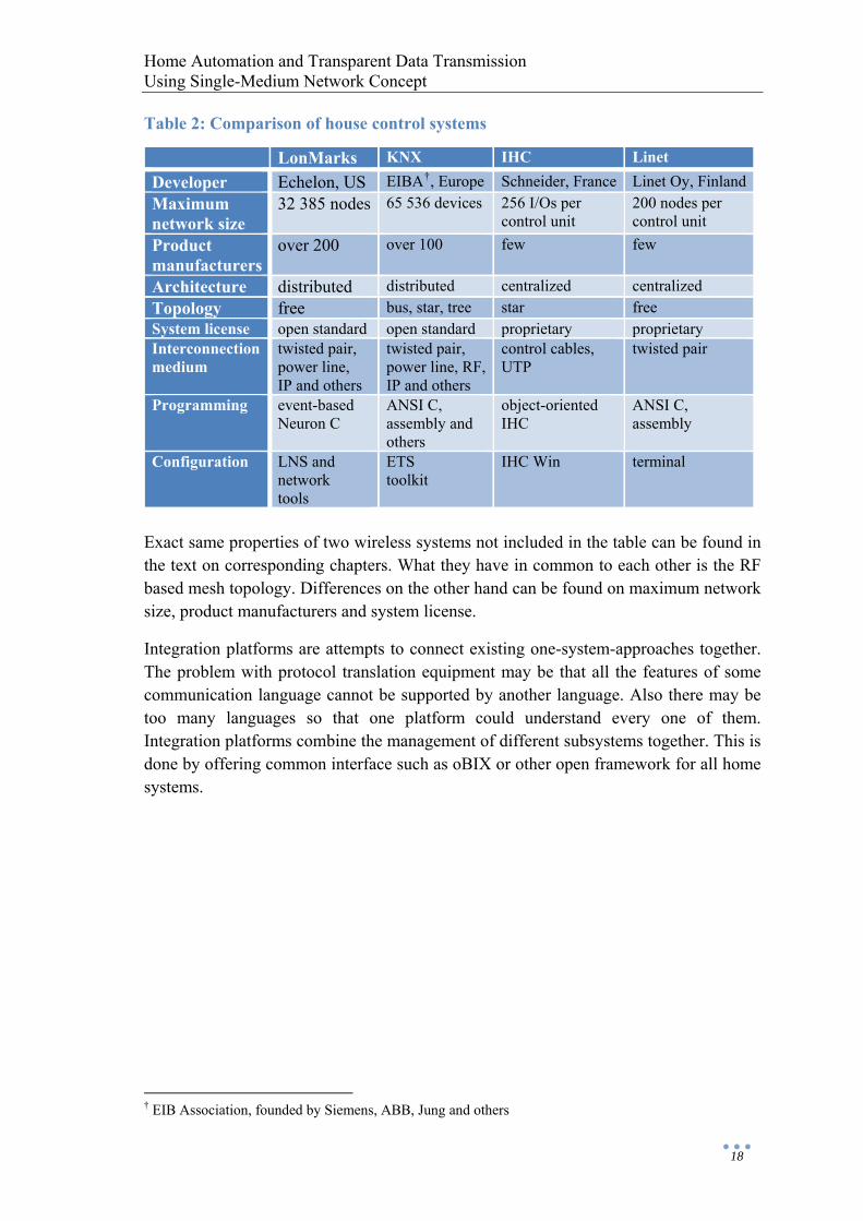
The overall architecture of Wiseriver is in between centralized and distributed architecture. Master is the main unit that controls the overall functionality but application programs for house control functions are distributed to access nodes. Control applications principally executed by access nodes form other logically centralized structures inside the main system.
Figure 8: Wiseriver system. The component on the top is master and the nine panel type components in the middle are access nodes. Physically connected devices are PC, network printer, IPTV and two sets of lights and switches. Virtual connections between desired devices are created electronically.
Logically Wiseriver network is wired as a ring. Data streams flow through every access node connected to the ring. The carrier frame that constantly circulates around the ring is used to give access to a shared medium by means of channels. Access nodes acquire time division multiplexed channels from the carrier frame circulating the ring.
A ring can be wired either as a physical ring called secured segment or an unclosed wire. The latter, non-secured segment still is logically a ring since data is forwarded back from the last access node in the segment. A node failure or a cable break in a normal segment isolates every node beyond the break point. The secured segment overcomes this vulnerability by wrapping the data back before the point of failure and thus resulting to two normal non-secured segments. Master can control four segments and act as a certain kind of switch or multiport bridge between them.
Cabling for Wiseriver’s infrastructure has been chosen to be 100BASE-TX which is one of Fast Ethernet standards for twisted pair. Wiseriver does not, however, utilize the data link layer (MAC) of Ethernet but only the physical layer which is used with standard connectors, wires, transducers, electrical levels and frequencies. Instead, Wiseriver’s
Segment 1
Segment 2
SecuredSegment 3+4
Externalnetwork
Home Automation and Transparent Data Transmission Using Single-Medium Network Concept
21
own internal transmission protocol runs on top of the physical layer and also the frame structure is proprietary. Wiseriver protocol (Layer 2 and above in OSI) offers flow control but error checking has been left to protocols at higher levels. Flow control is based on back-pressure and it is used on demand in shared channels to avoid congestion.
The channel access method is time divided multiplexing and bandwidth of each channel is configurable. Bandwidth allocation is done in flexible way between applications in multi-purpose network while providing transparent treatment of data streams despite of the type of equipments used. Transparency and protocol independence means that the data is treated as bit streams and represented at the transmitting end exactly in same format as it was received without reading or manipulating data structures. In order to do this Wiseriver technology includes different transmission modes to specify characteristics of transmissions (shared or dedicated medium, point-to-point or broadcast, half-duplex or full-duplex, constant or variable length data structure, packet mode or isochronous).
A special transmission mode designed for control applications is based on polling messages. An access node acting as an application master polls values from specified ports and passes them to a control application. Based on input data the application program calculates suitable output values and the access node sends data again to specified ports. Program code is executed in a soft core processor or in custom hardware logic. The application program and associated input/output ports can reside anywhere on the network. Home automation devices to be integrated in control applications must be connected to control application interfaces. A control service is applied on appropriate control channels and other transmission modes use universal data transmission channels.
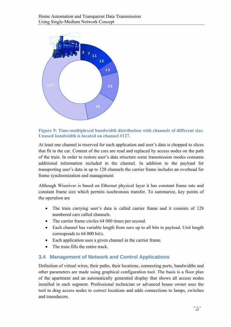
3.3 Principle of Transparent Data Transmission Basic structure in Wiseriver is the ring where the carrier frame is circulating. The carrier frame has a constant length and it is launched at 15.6 µs intervals (about 64 000 times per second). If the carrier frame is illustrated as a train and the ring as a track then the track is filled entirely by the train. Cars of the train represent time multiplexed channels for user’s data.
There are 128 cars and the length of the car can be modified and thus select the bandwidth of the channel. Unused cars have zero size allowing existing bandwidth to be used efficiently. Reserved channels are floating in the carrier frame. Bandwidths are reserved and released in few milliseconds for plug-and-play applications and variable bit rate applications. Bandwidth of a 1-bit wide channel is around 64 000 bits/s. Bit rate of a wider channel is simply multiple of 64 kbit/s depending on the width of the channel.
Home Automation and Transparent Data Transmission Using Single-Medium Network Concept
22
Figure 9: Time-multiplexed bandwidth distribution with channels of different size. Unused bandwidth is located on channel #127.
At least one channel is reserved for each application and user’s data is chopped to slices that fit in the car. Content of the cars are read and replaced by access nodes on the path of the train. In order to restore user’s data structure some transmission modes consume additional information included in the channel. In addition to the payload for transporting user’s data in up to 128 channels the carrier frame includes an overhead for frame synchronization and management.
Although Wiseriver is based on Ethernet physical layer it has constant frame rate and constant frame size which permits isochronous transfer. To summarize, key points of the operation are
• The train carrying user’s data is called carrier frame and it consists of 128 numbered cars called channels.
• The carrier frame circles 64 000 times per second. • Each channel has variable length from zero up to all bits in payload. Unit length
corresponds to 64 000 bit/s. • Each application uses a given channel in the carrier frame. • The train fills the entire track.
3.4 Management of Network and Control Applications Definition of virtual wires, their paths, their locations, connecting ports, bandwidths and other parameters are made using graphical configuration tool. The basis is a floor plan of the apartment and an automatically generated display that shows all access nodes installed in each segment. Professional technician or advanced house owner uses the tool to drag access nodes to correct locations and adds connections to lamps, switches and transducers.
3 7 1112
13
23
25
127
Home Automation and Transparent Data Transmission Using Single-Medium Network Concept
23
In order to put intelligence to control applications an application program has to be created for manipulating data that is retrieved using polling protocol. Programs are also made using the graphical configuration tool and a result is a script or other kind of program file. Possible operations that could be used in programs are NEG, AND, OR, LSHIFT, RHIFT, ADD, SUB, MUL and DIV. The application file is transferred to Wiseriver system through configuration management interface (Ethernet or USB) or through surveillance network from remote administrator. Depending on the final runtime system the actual program is executed by soft core processor or custom hardware logic in desired access node. More detailed bit-level discussion of the polling protocol is presented on the implementation section of this thesis.
Remote surveillance is available at any time. For example it is made possible for system administrator to enquire remotely device statuses or states of the ports. oBIX is useful data format for this purpose and also for making configurations. It is uncertain however at this point whether oBIX is suitable also for uploading application program data. Certainly it would be difficult to define actual program using just oBIX alone since it is mainly just a web service protocol.
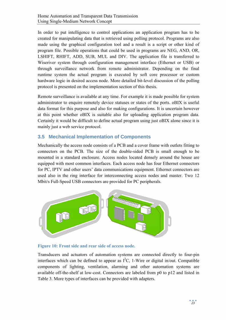
3.5 Mechanical Implementation of Components Mechanically the access node consists of a PCB and a cover frame with outlets fitting to connectors on the PCB. The size of the double-sided PCB is small enough to be mounted in a standard enclosure. Access nodes located densely around the house are equipped with most common interfaces. Each access node has four Ethernet connectors for PC, IPTV and other users’ data communications equipment. Ethernet connectors are used also in the ring interface for interconnecting access nodes and master. Two 12 Mbit/s Full-Speed USB connectors are provided for PC peripherals.
Figure 10: Front side and rear side of access node.
Transducers and actuators of automation systems are connected directly to four-pin interfaces which can be defined to appear as I2C, 1-Wire or digital in/out. Compatible components of lighting, ventilation, alarming and other automation systems are available off-the-shelf at low-cost. Connectors are labeled from p0 to p12 and listed in Table 3. More types of interfaces can be provided with adapters.
Home Automation and Transparent Data Transmission Using Single-Medium Network Concept
24
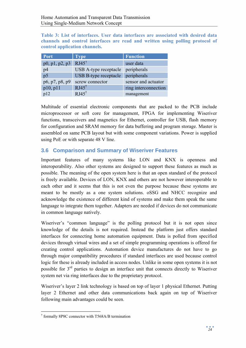
Table 3: List of interfaces. User data interfaces are associated with desired data channels and control interfaces are read and written using polling protocol of control application channels.
Port Type Function p0, p1, p2, p3 RJ45† user data p4 USB A-type receptacle peripherals p5 USB B-type receptacle peripherals p6, p7, p8, p9 screw connector sensor and actuator p10, p11 RJ45† ring interconnectionp12 RJ45† management
Multitude of essential electronic components that are packed to the PCB include microprocessor or soft core for management, FPGA for implementing Wiseriver functions, transceivers and magnetics for Ethernet, controller for USB, flash memory for configuration and SRAM memory for data buffering and program storage. Master is assembled on same PCB layout but with some component variations. Power is supplied using PoE or with separate 48 V line.
3.6 Comparison and Summary of Wiseriver Features Important features of many systems like LON and KNX is openness and interoperability. Also other systems are designed to support these features as much as possible. The meaning of the open system here is that an open standard of the protocol is freely available. Devices of LON, KNX and others are not however interoperable to each other and it seems that this is not even the purpose because these systems are meant to be mostly as a one system solutions. oSSG and NHCC recognize and acknowledge the existence of different kind of systems and make them speak the same language to integrate them together. Adapters are needed if devices do not communicate in common language natively.
Wiseriver’s “common language” is the polling protocol but it is not open since knowledge of the details is not required. Instead the platform just offers standard interfaces for connecting home automation equipment. Data is polled from specified devices through virtual wires and a set of simple programming operations is offered for creating control applications. Automation device manufactures do not have to go through major compatibility procedures if standard interfaces are used because control logic for these is already included in access nodes. Unlike in some open systems it is not possible for 3rd parties to design an interface unit that connects directly to Wiseriver system net via ring interfaces due to the proprietary protocol.
Wiseriver’s layer 2 link technology is based on top of layer 1 physical Ethernet. Putting layer 2 Ethernet and other data communications back again on top of Wiseriver following main advantages could be seen.
† formally 8P8C connector with T568A/B termination
Home Automation and Transparent Data Transmission Using Single-Medium Network Concept
25
• Easy and economical ring wiring but virtually full connectivity • Multiple independent connections of different types in a single medium • Definite resource sharing, guaranteed capacity for each application
Wiseriver functions are implemented using FPGA controller in master and access node components which is discussed in next chapter. Controllers are the basis on which the system architecture is defined at circuit level. FPGAs interface to the system net on one side and to user devices on the other. Also when considering the possibility to run application programs some resemblance could be seen when compared to Neuron chip of LON. Most relevant Wiseriver features are discussed in table below by summarizing comments.
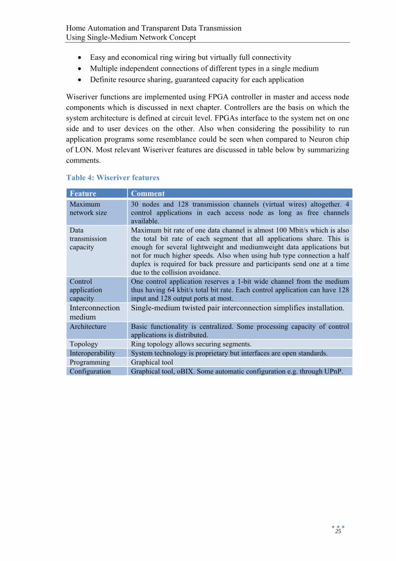
Table 4: Wiseriver features
Feature Comment Maximum network size
30 nodes and 128 transmission channels (virtual wires) altogether. 4 control applications in each access node as long as free channels available.
Data transmission capacity
Maximum bit rate of one data channel is almost 100 Mbit/s which is also the total bit rate of each segment that all applications share. This is enough for several lightweight and mediumweight data applications but not for much higher speeds. Also when using hub type connection a half duplex is required for back pressure and participants send one at a time due to the collision avoidance.
Control application capacity
One control application reserves a 1-bit wide channel from the medium thus having 64 kbit/s total bit rate. Each control application can have 128 input and 128 output ports at most.
Interconnection medium
Single-medium twisted pair interconnection simplifies installation.
Architecture Basic functionality is centralized. Some processing capacity of control applications is distributed.
Topology Ring topology allows securing segments. Interoperability System technology is proprietary but interfaces are open standards. Programming Graphical tool Configuration Graphical tool, oBIX. Some automatic configuration e.g. through UPnP.

Home Automation and Transparent Data Transmission Using Single-Medium Network Concept
26
4 Implementation of Wiseriver Functions with FPGA
The Wiseriver prototype system consists of a master and three access nodes in a single segment. This demo system does not implement all functions presented in Section 3 as several simplifications have been made. Components are connected into a physical ring but secured segment feature is not utilized. The configuration is fixed and consists of one control channel and four shared data channels for a simple digital light control application and universal data transmission. Data channels form four separate hubs including one Ethernet connector from each access node. In a hub access nodes can only transmit one at a time on the shared channel.
Consequently there is no graphical nor oBIX configuration interfaces. External buffered network interface and another control application for 1-Wire or I2C temperature regulation are under development. Higher level control application development is out of the scope of this thesis. Also Nios II and USB are not fully utilized in context of this thesis. The prototype is not ready to be used as a real life platform but is groundwork for developing a pilot system.
4.1 Lower-Level-Ring Controller (LLRC) LLRC is a controller located on the master PCB. Block diagram of FPGA logic is shown in the figure below. LLRC is responsible for generating the carrier frame and maintaining constant frame rate.
Figure 11: Partial block diagram of LLRC. Buffered net interfaces are located on the left side of the management block just like user device interfaces in ANC. From net interface block there is also connections to external SRAM buffers.
The management block generates the carrier frame by writing it in the output buffer. Carrier frame consists of an overhead and a payload and its generation is based on multiple synchronizing counters. For example a bit counter is used to count bit positions in the carrier frame and a frame counter is used to maintain multiframe synchronization. Multiframe concept is utilized especially in a polling protocol of control applications which is discussed in more detail later in this section. The overhead of each carrier
Lower-Level-Ring Controller
Ring IFManagement
PHY IFDPRAM
DPRAM
Ring Transceiver
Net IF
Buffer IF MDIO
Eth
erne
t Tra
nsce
iver
SR
AM
PHY IF
Home Automation and Transparent Data Transmission Using Single-Medium Network Concept
27
frame includes information of the channel configuration. The payload section consists of the users’ data circulating in the ring.
Depending on the length of the ring most of the carrier frame has usually arrived back from the ring before it is time to transmit it again. This is why there are dual-port RAMs in the ring interface having enough capacity to buffer the data of the whole frame. The management block maintains constant inter-frame gap and transfers data to output buffer from input buffer or from external network. PHY block just does the SMII synchronization and starts to transfer frame from output buffer to the transceiver.
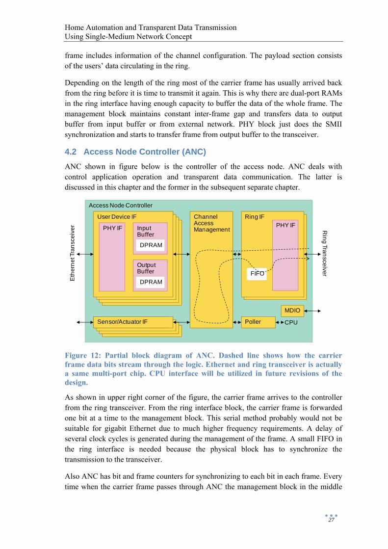
4.2 Access Node Controller (ANC) ANC shown in figure below is the controller of the access node. ANC deals with control application operation and transparent data communication. The latter is discussed in this chapter and the former in the subsequent separate chapter.
Figure 12: Partial block diagram of ANC. Dashed line shows how the carrier frame data bits stream through the logic. Ethernet and ring transceiver is actually a same multi-port chip. CPU interface will be utilized in future revisions of the design.
As shown in upper right corner of the figure, the carrier frame arrives to the controller from the ring transceiver. From the ring interface block, the carrier frame is forwarded one bit at a time to the management block. This serial method probably would not be suitable for gigabit Ethernet due to much higher frequency requirements. A delay of several clock cycles is generated during the management of the frame. A small FIFO in the ring interface is needed because the physical block has to synchronize the transmission to the transceiver.
Also ANC has bit and frame counters for synchronizing to each bit in each frame. Every time when the carrier frame passes through ANC the management block in the middle
Access Node Controller
Ring IFUser Device IF
PHY IF
ChannelAccessManagementInput
Buffer
DPRAM
OutputBuffer FIFO
Ring Transceiver
Eth
erne
t Tra
nsce
iver
Sensor/Actuator IF
PHY IF
DPRAM
Poller
MDIO
CPU
Home Automation and Transparent Data Transmission Using Single-Medium Network Concept
28
inspects the overhead section of the frame. If the channel or port configuration setup is changed then internal multiplexing registers are updated.
While processing the payload section the management block utilizes its internal logic that enables it to define when each channel contains valid data and when each channel is available for transmission. This decision is based on certain control bits that are transmitted in the channel. For example there is a specific R-bit that an access node can use to reserve the channel for itself. When the transmission is completed the access node releases the channel which is indicated by changing the state of the particular control bit. There are certain interoperation rules that define when each access node can modify control bit values.
On the left side of the Figure 12 there are user device interfaces. The management block in the middle of the figure gets data from buffer blocks and writes it in specified time slots in the carrier frame. Similarly in opposite direction valid data is extracted from the carrier frame and transferred to output buffers. Thus both incoming and outgoing user data is buffered inside the user interface block. Input and output buffers contain dual-port RAMs inferred from FPGA’s internal resources. Buffers have two layers and include also additional logic for restoring the user data structure from received data slices.
PHY interface block is the same as in the ring interface except for some generic parameters. The main difference is that PHY on the ring side is always in full-duplex mode but PHY on the user side may also work in half-duplex mode. PHY block is able to control the data flow arriving from the user device to prevent a buffer overflow.
4.3 Polling Protocol and Control Application Interfaces Sensor/actuator interfaces located on the left side of the block diagram transfer data between sensors/actuators and the management block. Control application data between sensor/actuator interfaces and the polling block is treated in the management block basically the same way as any data. Polling block on the right side of the management block is where the protocol is implemented and R-bit or other such additional information is not needed in the channel in this transmission mode.
In polling sequence a port read message is first sent to the control channel. When the reply is received from the specified interface the polled value would be normally passed to a processor. Here the demo application is simple enough so that the required logic can be included inside a single polling block. Finally new calculated control values are transmitted to defined ports using write messages via the control channel. For another application in the same access node a second polling block would be added.
Control channel is 1 bit wide and has bandwidth of 64 kbit/s. Thus polling protocol messages are transmitted one bit at a time in each carrier frame so that the whole message is completed during one multiframe. Different fields of the polling message are
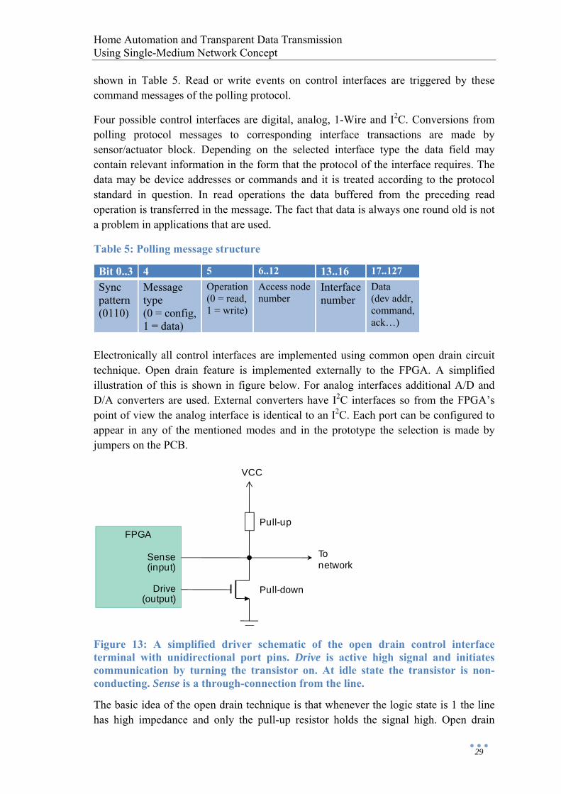
Home Automation and Transparent Data Transmission Using Single-Medium Network Concept
29
shown in Table 5. Read or write events on control interfaces are triggered by these command messages of the polling protocol.
Four possible control interfaces are digital, analog, 1-Wire and I2C. Conversions from polling protocol messages to corresponding interface transactions are made by sensor/actuator block. Depending on the selected interface type the data field may contain relevant information in the form that the protocol of the interface requires. The data may be device addresses or commands and it is treated according to the protocol standard in question. In read operations the data buffered from the preceding read operation is transferred in the message. The fact that data is always one round old is not a problem in applications that are used.
Table 5: Polling message structure
Bit 0..3 4 5 6..12 13..16 17..127 Sync pattern (0110)
Message type (0 = config, 1 = data)
Operation(0 = read, 1 = write)
Access node number
Interfacenumber
Data (dev addr, command, ack…)
Electronically all control interfaces are implemented using common open drain circuit technique. Open drain feature is implemented externally to the FPGA. A simplified illustration of this is shown in figure below. For analog interfaces additional A/D and D/A converters are used. External converters have I2C interfaces so from the FPGA’s point of view the analog interface is identical to an I2C. Each port can be configured to appear in any of the mentioned modes and in the prototype the selection is made by jumpers on the PCB.
Figure 13: A simplified driver schematic of the open drain control interface terminal with unidirectional port pins. Drive is active high signal and initiates communication by turning the transistor on. At idle state the transistor is non-conducting. Sense is a through-connection from the line.
The basic idea of the open drain technique is that whenever the logic state is 1 the line has high impedance and only the pull-up resistor holds the signal high. Open drain
FPGA
Sense(input)
Drive(output)
Pull-down
VCC
Pull-up
Tonetwork

Home Automation and Transparent Data Transmission Using Single-Medium Network Concept
30
terminals permit multiple devices to communicate on one wire. A device is in non-active state when the output is logic 1. Any device can now actively drive the line voltage to low. At the same time each device can sense the voltage level through the input pin. If open drain technique would not be used then the outputs of inactive devices would result unpredictable state on the bus.
It is shown in Figure 13 that FPGA has two normal unidirectional ports instead of one bidirectional tri-state port. Wiseriver uses advanced driver circuitry for 1-Wire that includes also dynamic pull-up, impedance matching and slew-rate control which are not shown in the figure. The digital in/out interface is easy because bits are just transferred as such on the I/O pins. 1-Wire and I2C (including analog) are much more sophisticated as they have specific communication protocols and master-slave relationships. It is not yet entirely clear how every feature of 1-Wire and I2C are treated using Wiseriver polling messages but discussion in following subchapters gives a short introduction to the topic.
4.3.1 1-Wire 1-Wire uses bidirectional half-duplex serial communication between a single master and multiple slaves. In most cases also a device power is derived parasitically from serial communication signaling and captured on internal capacitor. A single line can have hundreds of devices which are identified and operated using unique 64-bit ID. Maximum bit rate is around 64 kbit/s but communications can be speeded up by a factor of 10 when using overdrive mode. The protocol can be used to provide services on all ISO layers. [27]
A master generates signaling waveforms to identify devices and to communicate with them. Two types of waveforms are known by 1-Wire communications. These are reset/presence sequence and communication time slots. A data transfer in time slots is a method of operation whose synchronization is based on the falling edge generated by the master. One bit of information is sampled from the line at certain time after the slope.
Figure 14: A part of read sequence. Activity of the master is drawn in bold line. Thin line marks the response of the slave device. Dashed line indicates that a resistor is pulling the line high. Small arrows at the bottom denote sampling times.
There are several standard commands to address a particular device. Starting from LSB all commands and data are sent one bit at a time by concatenating write 1 and write 0 time slots. In opposite direction same timing rule is used. Master defines the beginning
’1’ ’1’ ’0’ ’1’ ’0’
T = 0µs T = 100µs T = 500µs
Home Automation and Transparent Data Transmission Using Single-Medium Network Concept
31
of each time slot simply initiating write 1 time slots asynchronously. When slave sends 1 it does not have to do anything. If slave has to send 0 it will hold the data line low for a specified time after the falling edge. A part of the receive sequence is shown in the Figure 14 as an example.
A basic transaction is a three-phase communication sequence consisting of a reset pulse, a device selection and a device function. If device IDs are not known beforehand then search procedure may be initiated. It is a binary tree enumeration algorithm to find the address of every device on the bus. Other operations at the network layer include commands for addressing specific device or setting devices into overdrive mode. After device selection a transport layer device functions are used for data transfer. Function commands are used for reading and writing memory locations, scratchpads, status information and passwords. Usually normal 8-bit commands are followed by data in 8-bit groups. [28]
In Wiseriver the access node is always the 1-Wire master. 1-Wire communication is handled by sending the data for the whole described 3-step procedure via a single polling protocol message. Control interface executes the transaction and a slave device response is sampled from the 1-Wire bus and stored in a register of FPGA logic. Next time when the polling application sends the same read message the data is transferred from buffer register to the message’s data field. Control application receives the data when the message circulates in the ring back to the polling block. It is intended that in most cases there is just one device connected to each control interface.
Control channel of the Wiseriver has the exact same 64 kbit/s bandwidth than the standard mode of 1-Wire. This could in principle allow execution of transactions while data bits are received from the control channel. Furthermore it could be possible to append the device response from the bus to the polling message that initiates the transaction in the first place. However, the choice has been made to buffer transactions because the only drawback of this approach is the one round delay between the read request message and actual read data.
4.3.2 Inter-Integrated Circuit (I2C) I2C is used to attach low-speed peripherals to embedded systems. Additionally it is common in several control architectures. The interface uses two open-drain lines as opposed to a single line in 1-Wire so I2C is a bidirectional 2-wire bus. These two bus lines are a clock and a serial data. Each control interface in the access node includes two lines but the other one is just not used in case of 1-Wire.
In the same way as in 1-Wire each device connected to the bus is addressable by a unique address. The difference is that I2C can have multiple masters by the aid of collision detection and arbitration mechanism. I2C can also have higher data rates up to several megabits per second in a high-speed mode. A standard mode however has a bit rate up to 100 kbit/s.
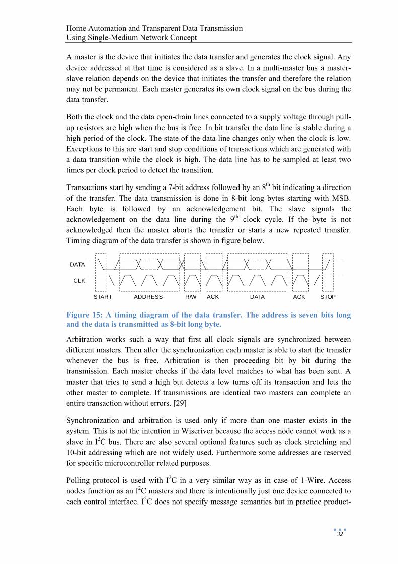
Home Automation and Transparent Data Transmission Using Single-Medium Network Concept
32
A master is the device that initiates the data transfer and generates the clock signal. Any device addressed at that time is considered as a slave. In a multi-master bus a master-slave relation depends on the device that initiates the transfer and therefore the relation may not be permanent. Each master generates its own clock signal on the bus during the data transfer.
Both the clock and the data open-drain lines connected to a supply voltage through pull-up resistors are high when the bus is free. In bit transfer the data line is stable during a high period of the clock. The state of the data line changes only when the clock is low. Exceptions to this are start and stop conditions of transactions which are generated with a data transition while the clock is high. The data line has to be sampled at least two times per clock period to detect the transition.
Transactions start by sending a 7-bit address followed by an 8th bit indicating a direction of the transfer. The data transmission is done in 8-bit long bytes starting with MSB. Each byte is followed by an acknowledgement bit. The slave signals the acknowledgement on the data line during the 9th clock cycle. If the byte is not acknowledged then the master aborts the transfer or starts a new repeated transfer. Timing diagram of the data transfer is shown in figure below.
Figure 15: A timing diagram of the data transfer. The address is seven bits long and the data is transmitted as 8-bit long byte.
Arbitration works such a way that first all clock signals are synchronized between different masters. Then after the synchronization each master is able to start the transfer whenever the bus is free. Arbitration is then proceeding bit by bit during the transmission. Each master checks if the data level matches to what has been sent. A master that tries to send a high but detects a low turns off its transaction and lets the other master to complete. If transmissions are identical two masters can complete an entire transaction without errors. [29]
Synchronization and arbitration is used only if more than one master exists in the system. This is not the intention in Wiseriver because the access node cannot work as a slave in I2C bus. There are also several optional features such as clock stretching and 10-bit addressing which are not widely used. Furthermore some addresses are reserved for specific microcontroller related purposes.
Polling protocol is used with I2C in a very similar way as in case of 1-Wire. Access nodes function as an I2C masters and there is intentionally just one device connected to each control interface. I2C does not specify message semantics but in practice product-
CLK
DATA
START ADDRESS R/W ACK DATA ACK STOP
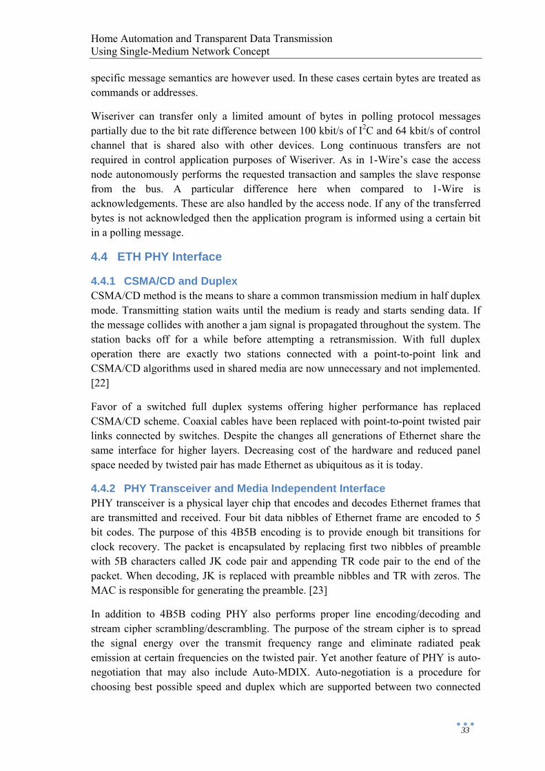
Home Automation and Transparent Data Transmission Using Single-Medium Network Concept
33
specific message semantics are however used. In these cases certain bytes are treated as commands or addresses.
Wiseriver can transfer only a limited amount of bytes in polling protocol messages partially due to the bit rate difference between 100 kbit/s of I2C and 64 kbit/s of control channel that is shared also with other devices. Long continuous transfers are not required in control application purposes of Wiseriver. As in 1-Wire’s case the access node autonomously performs the requested transaction and samples the slave response from the bus. A particular difference here when compared to 1-Wire is acknowledgements. These are also handled by the access node. If any of the transferred bytes is not acknowledged then the application program is informed using a certain bit in a polling message.
4.4 ETH PHY Interface
4.4.1 CSMA/CD and Duplex CSMA/CD method is the means to share a common transmission medium in half duplex mode. Transmitting station waits until the medium is ready and starts sending data. If the message collides with another a jam signal is propagated throughout the system. The station backs off for a while before attempting a retransmission. With full duplex operation there are exactly two stations connected with a point-to-point link and CSMA/CD algorithms used in shared media are now unnecessary and not implemented. [22]
Favor of a switched full duplex systems offering higher performance has replaced CSMA/CD scheme. Coaxial cables have been replaced with point-to-point twisted pair links connected by switches. Despite the changes all generations of Ethernet share the same interface for higher layers. Decreasing cost of the hardware and reduced panel space needed by twisted pair has made Ethernet as ubiquitous as it is today.
4.4.2 PHY Transceiver and Media Independent Interface PHY transceiver is a physical layer chip that encodes and decodes Ethernet frames that are transmitted and received. Four bit data nibbles of Ethernet frame are encoded to 5 bit codes. The purpose of this 4B5B encoding is to provide enough bit transitions for clock recovery. The packet is encapsulated by replacing first two nibbles of preamble with 5B characters called JK code pair and appending TR code pair to the end of the packet. When decoding, JK is replaced with preamble nibbles and TR with zeros. The MAC is responsible for generating the preamble. [23]
In addition to 4B5B coding PHY also performs proper line encoding/decoding and stream cipher scrambling/descrambling. The purpose of the stream cipher is to spread the signal energy over the transmit frequency range and eliminate radiated peak emission at certain frequencies on the twisted pair. Yet another feature of PHY is auto-negotiation that may also include Auto-MDIX. Auto-negotiation is a procedure for choosing best possible speed and duplex which are supported between two connected
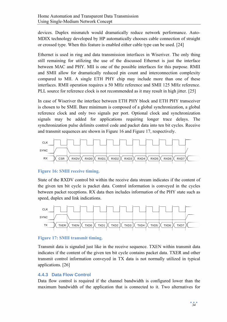
Home Automation and Transparent Data Transmission Using Single-Medium Network Concept
34
devices. Duplex mismatch would dramatically reduce network performance. Auto-MDIX technology developed by HP automatically chooses cable connection of straight or crossed type. When this feature is enabled either cable type can be used. [24]
Ethernet is used in ring and data transmission interfaces in Wiseriver. The only thing still remaining for utilizing the use of the discussed Ethernet is just the interface between MAC and PHY. MII is one of the possible interfaces for this purpose. RMII and SMII allow for dramatically reduced pin count and interconnection complexity compared to MII. A single ETH PHY chip may include more than one of these interfaces. RMII operation requires a 50 MHz reference and SMII 125 MHz reference. PLL source for reference clock is not recommended as it may result in high jitter. [25]
In case of Wiseriver the interface between ETH PHY block and ETH PHY transceiver is chosen to be SMII. Bare minimum is composed of a global synchronization, a global reference clock and only two signals per port. Optional clock and synchronization signals may be added for applications requiring longer trace delays. The synchronization pulse delimits control code and packet data into ten bit cycles. Receive and transmit sequences are shown in Figure 16 and Figure 17, respectively.
Figure 16: SMII receive timing.
State of the RXDV control bit within the receive data stream indicates if the content of the given ten bit cycle is packet data. Control information is conveyed in the cycles between packet receptions. RX data then includes information of the PHY state such as speed, duplex and link indications.
Figure 17: SMII transmit timing.
Transmit data is signaled just like in the receive sequence. TXEN within transmit data indicates if the content of the given ten bit cycle contains packet data. TXER and other transmit control information conveyed in TX data is not normally utilized in typical applications. [26]
4.4.3 Data Flow Control Data flow control is required if the channel bandwidth is configured lower than the maximum bandwidth of the application that is connected to it. Two alternatives for
CSR RXDV RXD0 RXD1 RXD2 RXD3 RXD4 RXD5 RXD6 RXD7
CLK
SYNC
RX
TXER TXEN TXD0 TXD1 TXD2 TXD3 TXD4 TXD5 TXD6 TXD7
CLK
SYNC
TX
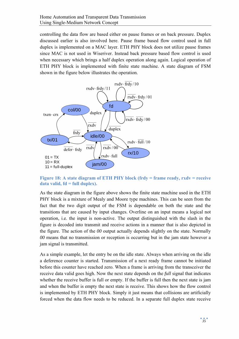
Home Automation and Transparent Data Transmission Using Single-Medium Network Concept
35
controlling the data flow are based either on pause frames or on back pressure. Duplex discussed earlier is also involved here. Pause frame based flow control used in full duplex is implemented on a MAC layer. ETH PHY block does not utilize pause frames since MAC is not used in Wiseriver. Instead back pressure based flow control is used when necessary which brings a half duplex operation along again. Logical operation of ETH PHY block is implemented with finite state machine. A state diagram of FSM shown in the figure below illustrates the operation.
Figure 18: A state diagram of ETH PHY block (frdy = frame ready, rxdv = receive data valid, fd = full duplex).
As the state diagram in the figure above shows the finite state machine used in the ETH PHY block is a mixture of Mealy and Moore type machines. This can be seen from the fact that the two digit output of the FSM is dependable on both the state and the transitions that are caused by input changes. Overline on an input means a logical not operation, i.e. the input is non-active. The output distinguished with the slash in the figure is decoded into transmit and receive actions in a manner that is also depicted in the figure. The action of the 00 output actually depends slightly on the state. Normally 00 means that no transmission or reception is occurring but in the jam state however a jam signal is transmitted.
As a simple example, let the entry be on the idle state. Always when arriving on the idle a deference counter is started. Transmission of a next ready frame cannot be initiated before this counter have reached zero. When a frame is arriving from the transceiver the receive data valid goes high. Now the next state depends on the full signal that indicates whether the receive buffer is full or empty. If the buffer is full then the next state is jam and when the buffer is empty the next state is receive. This shows how the flow control is implemented by ETH PHY block. Simply it just means that collisions are artificially forced when the data flow needs to be reduced. In a separate full duplex state receive
idle/00
rx/10
jam/00
col/00
tx/01
fd
11/frdyrxdv ⋅
01/frdyrxdv ⋅
10/frdyrxdv ⋅
00/frdyrxdv ⋅duplex
duplex
10/fullrxdv ⋅00/rxdv
fullrxdv ⋅
rxdv
frdy
frdydefer ⋅
crstxen ⋅
rxdv
01 = TX10 = RX11 = full-duplex
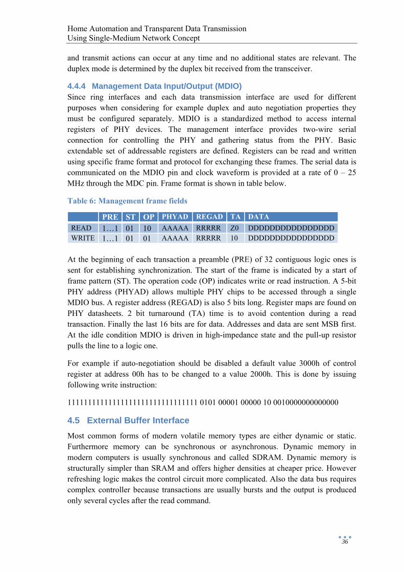
Home Automation and Transparent Data Transmission Using Single-Medium Network Concept
36
and transmit actions can occur at any time and no additional states are relevant. The duplex mode is determined by the duplex bit received from the transceiver.
4.4.4 Management Data Input/Output (MDIO) Since ring interfaces and each data transmission interface are used for different purposes when considering for example duplex and auto negotiation properties they must be configured separately. MDIO is a standardized method to access internal registers of PHY devices. The management interface provides two-wire serial connection for controlling the PHY and gathering status from the PHY. Basic extendable set of addressable registers are defined. Registers can be read and written using specific frame format and protocol for exchanging these frames. The serial data is communicated on the MDIO pin and clock waveform is provided at a rate of 0 – 25 MHz through the MDC pin. Frame format is shown in table below.
Table 6: Management frame fields
PRE ST OP PHYAD REGAD TA DATA READ 1…1 01 10 AAAAA RRRRR Z0 DDDDDDDDDDDDDDDDWRITE 1…1 01 01 AAAAA RRRRR 10 DDDDDDDDDDDDDDDD
At the beginning of each transaction a preamble (PRE) of 32 contiguous logic ones is sent for establishing synchronization. The start of the frame is indicated by a start of frame pattern (ST). The operation code (OP) indicates write or read instruction. A 5-bit PHY address (PHYAD) allows multiple PHY chips to be accessed through a single MDIO bus. A register address (REGAD) is also 5 bits long. Register maps are found on PHY datasheets. 2 bit turnaround (TA) time is to avoid contention during a read transaction. Finally the last 16 bits are for data. Addresses and data are sent MSB first. At the idle condition MDIO is driven in high-impedance state and the pull-up resistor pulls the line to a logic one.
For example if auto-negotiation should be disabled a default value 3000h of control register at address 00h has to be changed to a value 2000h. This is done by issuing following write instruction:
11111111111111111111111111111111 0101 00001 00000 10 0010000000000000
4.5 External Buffer Interface Most common forms of modern volatile memory types are either dynamic or static. Furthermore memory can be synchronous or asynchronous. Dynamic memory in modern computers is usually synchronous and called SDRAM. Dynamic memory is structurally simpler than SRAM and offers higher densities at cheaper price. However refreshing logic makes the control circuit more complicated. Also the data bus requires complex controller because transactions are usually bursts and the output is produced only several cycles after the read command.
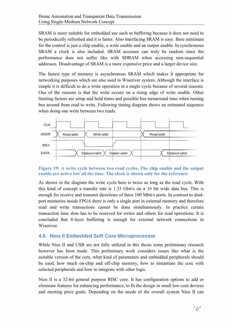
Home Automation and Transparent Data Transmission Using Single-Medium Network Concept
37
SRAM is more suitable for embedded use such as buffering because it does not need to be periodically refreshed and it is faster. Also interfacing SRAM is easy. Bare minimum for the control is just a chip enable, a write enable and an output enable. In synchronous SRAM a clock is also included. SRAM accesses can truly be random since the performance does not suffer like with SDRAM when accessing non-sequential addresses. Disadvantage of SRAM is a more expensive price and a larger device size.
The fastest type of memory is asynchronous SRAM which makes it appropriate for networking purposes which are also used in Wiseriver system. Although the interface is simple it is difficult to do a write operation in a single cycle because of several reasons. One of the reasons is that the write occurs on a rising edge of write enable. Other limiting factors are setup and hold times and possible bus turnaround time when turning bus around from read to write. Following timing diagram shows an estimated sequence when doing one write between two reads.
Figure 19: A write cycle between two read cycles. The chip enable and the output enable are active low all the time. The clock is shown only for the reference.
As shown in the diagram the write cycle here is twice as long as the read cycle. With this kind of concept a transfer rate is 1.33 Gbit/s on a 16 bit wide data bus. This is enough for receive and transmit directions of three 100 Mbit/s ports. In contrast to dual-port memories inside FPGA there is only a single port in external memory and therefore read and write transactions cannot be done simultaneously. In practice certain transaction time slots has to be reserved for writes and others for read operations. It is concluded that 8-layer buffering is enough for external network connections in Wiseriver.
4.6 Nios II Embedded Soft Core Microprocessor While Nios II and USB are not fully utilized in this thesis some preliminary research however has been made. This preliminary work considers issues like what is the suitable version of the core, what kind of parameters and embedded peripherals should be used, how much on-chip and off-chip memory, how to instantiate the core with selected peripherals and how to integrate with other logic.
Nios II is a 32-bit general purpose RISC core. It has configuration options to add or eliminate features for enhancing performance, to fit the design in small low-cost devices and meeting price goals. Depending on the needs of the overall system Nios II can
Read addr Write addr
Dataout valid Datain valid
Read addr
Dataout valid
CLK
ADDR
WEn
DATA
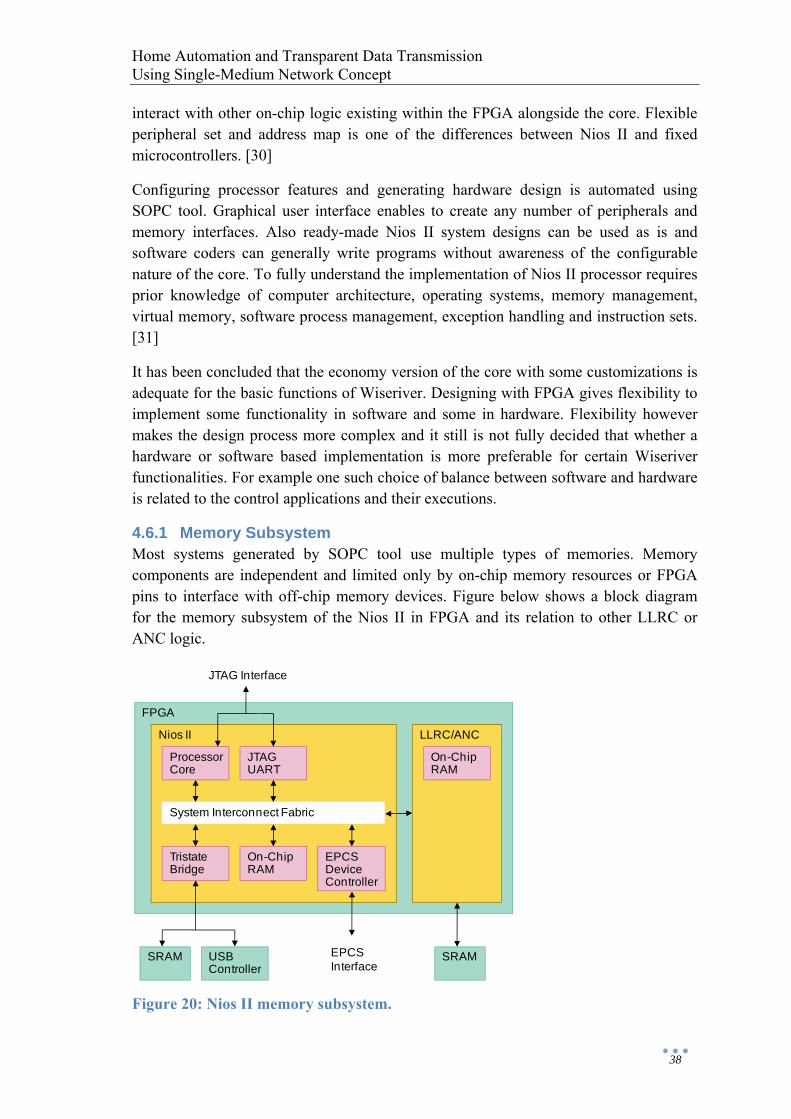
Home Automation and Transparent Data Transmission Using Single-Medium Network Concept
38
interact with other on-chip logic existing within the FPGA alongside the core. Flexible peripheral set and address map is one of the differences between Nios II and fixed microcontrollers. [30]
Configuring processor features and generating hardware design is automated using SOPC tool. Graphical user interface enables to create any number of peripherals and memory interfaces. Also ready-made Nios II system designs can be used as is and software coders can generally write programs without awareness of the configurable nature of the core. To fully understand the implementation of Nios II processor requires prior knowledge of computer architecture, operating systems, memory management, virtual memory, software process management, exception handling and instruction sets. [31]
It has been concluded that the economy version of the core with some customizations is adequate for the basic functions of Wiseriver. Designing with FPGA gives flexibility to implement some functionality in software and some in hardware. Flexibility however makes the design process more complex and it still is not fully decided that whether a hardware or software based implementation is more preferable for certain Wiseriver functionalities. For example one such choice of balance between software and hardware is related to the control applications and their executions.
4.6.1 Memory Subsystem Most systems generated by SOPC tool use multiple types of memories. Memory components are independent and limited only by on-chip memory resources or FPGA pins to interface with off-chip memory devices. Figure below shows a block diagram for the memory subsystem of the Nios II in FPGA and its relation to other LLRC or ANC logic.
Figure 20: Nios II memory subsystem.
FPGA
Nios II
ProcessorCore
LLRC/ANC
System Interconnect Fabric
SRAM
JTAGUART
TristateBridge
On-ChipRAM
On-ChipRAM
EPCSDeviceController
USBController
JTAG Interface
SRAMEPCSInterface
Home Automation and Transparent Data Transmission Using Single-Medium Network Concept
39
Advantages of on-chip memory are that it is fast, it can have dual-port mode and it can be initialized to have code data at FPGA configuration. It is also possible to enable in-system content editor feature. JTAG interface is then used to read and write to the RAM while it is operating. A disadvantage of on-chip memory is somewhat limited amount of capacity.
Serial configuration device (EPCS) is used to configure the FPGA. EPCS serial flash controller component allows SOPC to reprogram its own configuration memory providing mechanism for remote upgrades. SOPC design can also use leftover space in the serial flash memory device as nonvolatile storage.
SRAM memories are used for buffering and Nios II software storage. Buffering is not needed in the access node so only the master has two SRAM devices. Nios II can access SRAM device directly without additional controller cores. Standard memory interfaces can be described directly by system interconnection fabric signals. Size of the off-chip memory is bounded by the 32-bit address space that is always byte addressed. SRAM bus is shared with USB driver using tri-state bridge component in order to share bidirectional pins. Special care is exercised when ensuring correct address bit alignment and timing parameters.
4.6.2 System Interconnection Fabric (Avalon) When Nios II is added in FPGA design a processor interface from the other logic is needed. Avalon memory-mapped system interconnection fabric is used to specify connectivity between components of the system. Custom logic can be integrated inside or outside of SOPC. In a former case custom logic is defined as a custom component inside the system. This is done by importing HDL logic modules to the system and determining the interface with SOPC tool. A custom logic outside of SOPC is connected to the system through Avalon interface just like off-chip devices such as memories.
Avalon is a cross-connect fabric and not a tri-stated bus. It interconnects any number of Avalon master and slave components in different combinations in the system. Some of the memory-mapped interconnect fabric features are address decoding, datapath multiplexing, wait state insertion, pipelined read transfers, dynamic bus sizing, arbitration for multi-master systems and interrupts. Address decoding aligns addresses and creates chip selects for slaves that may have different address widths. Datapath multiplexer drives data signals between selected slave and granted master. Wait state insertion and pipelined read transfers can be used to improve throughput of low latency slaves. Dynamic bus sizing together with address alignment hides the details of interfacing between narrow and wide components.
The interface between Nios II and custom logic handling Wiseriver functions is a normal Avalon-compatible memory-mapped slave interface. From SOPC’s point of view the component file describes only the interface to the external logic. The interface is exported on the top level of Nios II system and signals are manually connected to the
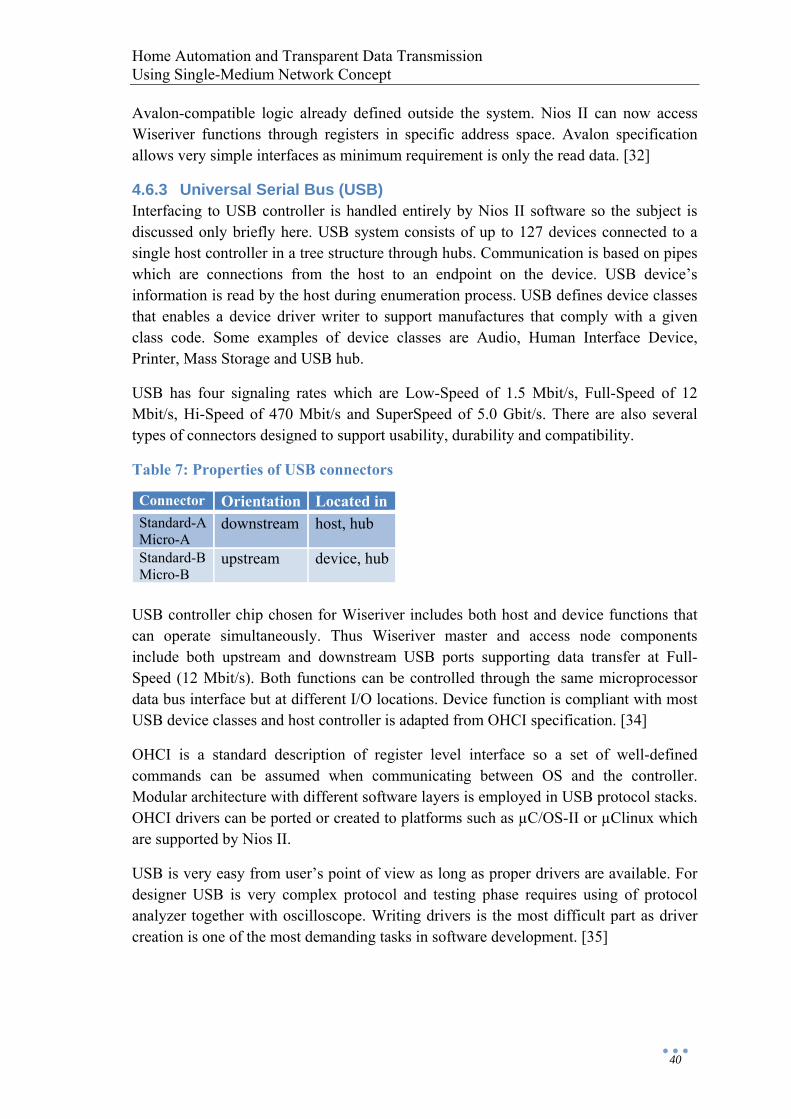
Home Automation and Transparent Data Transmission Using Single-Medium Network Concept
40
Avalon-compatible logic already defined outside the system. Nios II can now access Wiseriver functions through registers in specific address space. Avalon specification allows very simple interfaces as minimum requirement is only the read data. [32]
4.6.3 Universal Serial Bus (USB) Interfacing to USB controller is handled entirely by Nios II software so the subject is discussed only briefly here. USB system consists of up to 127 devices connected to a single host controller in a tree structure through hubs. Communication is based on pipes which are connections from the host to an endpoint on the device. USB device’s information is read by the host during enumeration process. USB defines device classes that enables a device driver writer to support manufactures that comply with a given class code. Some examples of device classes are Audio, Human Interface Device, Printer, Mass Storage and USB hub.
USB has four signaling rates which are Low-Speed of 1.5 Mbit/s, Full-Speed of 12 Mbit/s, Hi-Speed of 470 Mbit/s and SuperSpeed of 5.0 Gbit/s. There are also several types of connectors designed to support usability, durability and compatibility.
Table 7: Properties of USB connectors
Connector Orientation Located inStandard-A Micro-A
downstream host, hub
Standard-B Micro-B
upstream device, hub
USB controller chip chosen for Wiseriver includes both host and device functions that can operate simultaneously. Thus Wiseriver master and access node components include both upstream and downstream USB ports supporting data transfer at Full-Speed (12 Mbit/s). Both functions can be controlled through the same microprocessor data bus interface but at different I/O locations. Device function is compliant with most USB device classes and host controller is adapted from OHCI specification. [34]
OHCI is a standard description of register level interface so a set of well-defined commands can be assumed when communicating between OS and the controller. Modular architecture with different software layers is employed in USB protocol stacks. OHCI drivers can be ported or created to platforms such as µC/OS-II or µClinux which are supported by Nios II.
USB is very easy from user’s point of view as long as proper drivers are available. For designer USB is very complex protocol and testing phase requires using of protocol analyzer together with oscilloscope. Writing drivers is the most difficult part as driver creation is one of the most demanding tasks in software development. [35]

Home Automation and Transparent Data Transmission Using Single-Medium Network Concept
41
5 Wiseriver Prototype
5.1 Functional Simulation A top level of the simulation testbench is illustrated in the figure below. In this simulation setup there are one master and three access nodes instantiated and interconnected as a ring. Some simplifications have been made to limit the simulation time. Normally there would be PHY transceivers and magnetics in the path between components. However, as shown in the figure, ring outputs are connected to inputs of the adjacent component with a direct SMII-SMII connection. Also the carrier frame, the multiframe and the stimulus frame sizes have been reduced. Basic functionality of the network is tested with these simplifications. Behavioral VHDL models of user devices are connected to each user device port and each model reads its simulation stimulus from the plain text file.
Figure 21: Testbench top level.
Syntax of the stimulus file is very simple. Each model has an id number given with a generic parameter and in the stimulus file there is defined how many bytes each model is going to send. One line in the stimulus file corresponds to one packet. The stimulus file seen in the figure shows for example that a 10-byte packet is defined first for the model that has an id 0. Then for the model 1 next packet is defined, now size of 20 bytes.
Test packets are filled with a pseudorandom byte sequence except for the first byte which includes the number of the packet. The user device model can recognize the packet with this number and check that the transfer has occurred correctly and without any bit errors. The network is configured as a hub and every device connected to the same channel share the medium. This means that the channel is not available all the
Master
AccessNode 1
User device model
AccessNode 2
User device model
AccessNode 3
User device model
0 101 20…
”stim.txt”

Home Automation and Transparent Data Transmission Using Single-Medium Network Concept
42
time and it affects on the throughput. A cumulative bit rate of the transfer is reported after each packet.
The control application for lighting is tested by just defining some fixed setting for all input ports, i.e. switches. Output ports that will control lamps are monitored during the simulation and state changes are reported. Intended response for each setting can be ensured by observing test reports.
An example run of a testbench simulation is shown in the Appendix. In a related stimulus file four pseudorandom test packets are defined for each user device port. The size of the packet varies between 10–20 bytes. A small glitch is artificially created to a data signal to check if the testbench will detect the error. In this example stimuli are numbered starting from 10 and the error appears in the stimulus #37.
As control events progress relatively slower when compared to the data transmission it is cumbersome to simulate them more thoroughly. Particularly when Nios II and more complex control applications are involved the best way to test all the functionality is verification in hardware. Same applies to SRAM buffering and MDIO because it is difficult to accurately model external devices. Exact operation of external interfaces, their timing requirements and other properties are discovered when actual components are assembled to the prototype and tested there as a complete system. More simulation issues related to Nios II are addressed in the Chapter 5.2.1.
5.2 Synthesis for FPGA Design After writing the VHDL code design entry and verifying it with functional simulations the design flow proceeds to the synthesis that is performed by taking following steps with the synthesis tool.
1. Create a project and select an appropriate device and other settings. 2. Add possible megafunctions and other pre-designed IP blocks (e.g. Nios II and
PLL modules) at the top level of the design. 3. Create pin assignments and industry-standard timing constraints. 4. Run synthesis and place & route. 5. Run timing analysis and check for possible timing violations reported as a slack
in timing report.
During initial synthesis an optional netlist is created. This netlist may be used as an intermediate step for continuing the synthesis with another tool or making additional timing analyses or timing simulations. After required logic and physical syntheses a place and route is performed by the fitter. Timing constraints created in the previous step now help to guide the fitter to achieve a timing closure. If timing constraints are not met at the end in the step 5 a general recommendation would be to review timing constraints or select a device with a faster speed grade. There are however several other actions that can be taken.
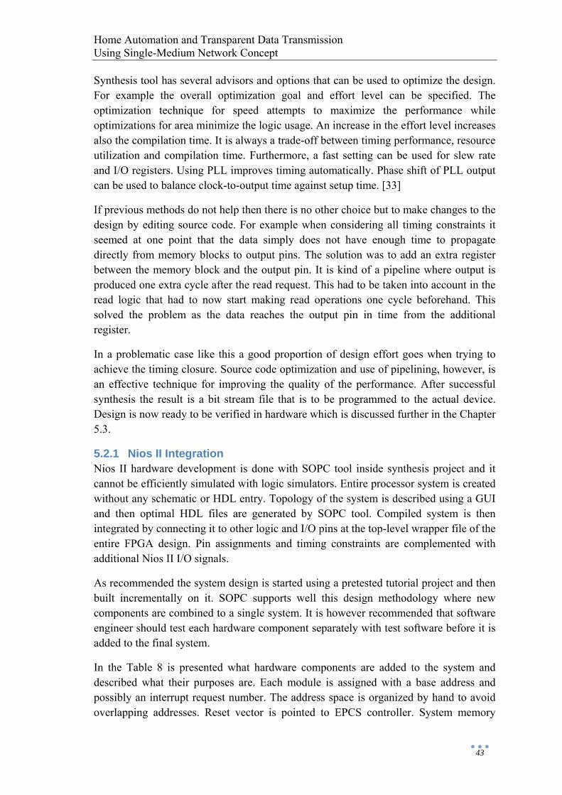
Home Automation and Transparent Data Transmission Using Single-Medium Network Concept
43
Synthesis tool has several advisors and options that can be used to optimize the design. For example the overall optimization goal and effort level can be specified. The optimization technique for speed attempts to maximize the performance while optimizations for area minimize the logic usage. An increase in the effort level increases also the compilation time. It is always a trade-off between timing performance, resource utilization and compilation time. Furthermore, a fast setting can be used for slew rate and I/O registers. Using PLL improves timing automatically. Phase shift of PLL output can be used to balance clock-to-output time against setup time. [33]
If previous methods do not help then there is no other choice but to make changes to the design by editing source code. For example when considering all timing constraints it seemed at one point that the data simply does not have enough time to propagate directly from memory blocks to output pins. The solution was to add an extra register between the memory block and the output pin. It is kind of a pipeline where output is produced one extra cycle after the read request. This had to be taken into account in the read logic that had to now start making read operations one cycle beforehand. This solved the problem as the data reaches the output pin in time from the additional register.
In a problematic case like this a good proportion of design effort goes when trying to achieve the timing closure. Source code optimization and use of pipelining, however, is an effective technique for improving the quality of the performance. After successful synthesis the result is a bit stream file that is to be programmed to the actual device. Design is now ready to be verified in hardware which is discussed further in the Chapter 5.3.
5.2.1 Nios II Integration Nios II hardware development is done with SOPC tool inside synthesis project and it cannot be efficiently simulated with logic simulators. Entire processor system is created without any schematic or HDL entry. Topology of the system is described using a GUI and then optimal HDL files are generated by SOPC tool. Compiled system is then integrated by connecting it to other logic and I/O pins at the top-level wrapper file of the entire FPGA design. Pin assignments and timing constraints are complemented with additional Nios II I/O signals.
As recommended the system design is started using a pretested tutorial project and then built incrementally on it. SOPC supports well this design methodology where new components are combined to a single system. It is however recommended that software engineer should test each hardware component separately with test software before it is added to the final system.
In the Table 8 is presented what hardware components are added to the system and described what their purposes are. Each module is assigned with a base address and possibly an interrupt request number. The address space is organized by hand to avoid overlapping addresses. Reset vector is pointed to EPCS controller. System memory
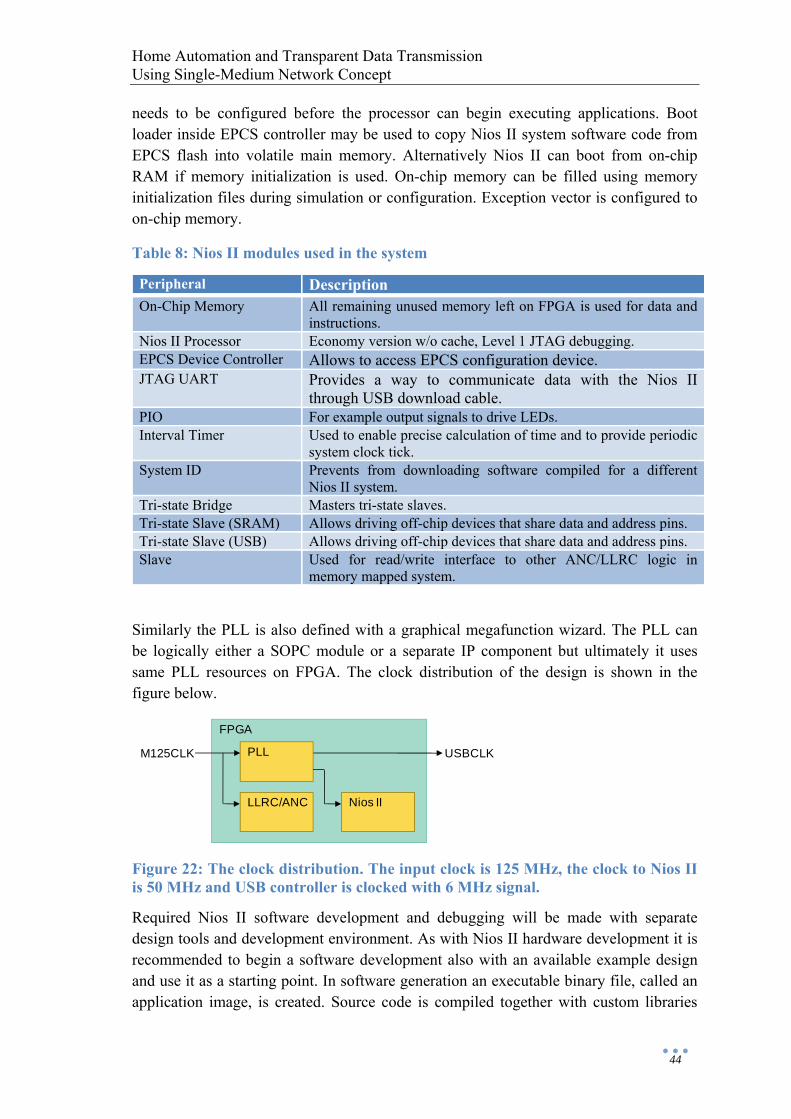
Home Automation and Transparent Data Transmission Using Single-Medium Network Concept
44
needs to be configured before the processor can begin executing applications. Boot loader inside EPCS controller may be used to copy Nios II system software code from EPCS flash into volatile main memory. Alternatively Nios II can boot from on-chip RAM if memory initialization is used. On-chip memory can be filled using memory initialization files during simulation or configuration. Exception vector is configured to on-chip memory.
Table 8: Nios II modules used in the system
Peripheral Description On-Chip Memory All remaining unused memory left on FPGA is used for data and
instructions. Nios II Processor Economy version w/o cache, Level 1 JTAG debugging. EPCS Device Controller Allows to access EPCS configuration device. JTAG UART Provides a way to communicate data with the Nios II
through USB download cable. PIO For example output signals to drive LEDs. Interval Timer Used to enable precise calculation of time and to provide periodic
system clock tick. System ID Prevents from downloading software compiled for a different
Nios II system. Tri-state Bridge Masters tri-state slaves. Tri-state Slave (SRAM) Allows driving off-chip devices that share data and address pins. Tri-state Slave (USB) Allows driving off-chip devices that share data and address pins. Slave Used for read/write interface to other ANC/LLRC logic in
memory mapped system.
Similarly the PLL is also defined with a graphical megafunction wizard. The PLL can be logically either a SOPC module or a separate IP component but ultimately it uses same PLL resources on FPGA. The clock distribution of the design is shown in the figure below.
Figure 22: The clock distribution. The input clock is 125 MHz, the clock to Nios II is 50 MHz and USB controller is clocked with 6 MHz signal.
Required Nios II software development and debugging will be made with separate design tools and development environment. As with Nios II hardware development it is recommended to begin a software development also with an available example design and use it as a starting point. In software generation an executable binary file, called an application image, is created. Source code is compiled together with custom libraries
FPGA
Nios IILLRC/ANC
PLLM125CLK USBCLK
Home Automation and Transparent Data Transmission Using Single-Medium Network Concept
45
which are built using specifications that describe hardware components and connections. Coherence should be maintained between software and hardware development. Nios II software includes also several debugging tools and techniques to address difficult embedded design problems.
Applications can be executed with instruction set simulator or in actual hardware. Simulations with a logic simulator are also possible but this is most time-consuming. SOPC generates automatically some generic memory models for some components used in the system but not for SRAM. EPCS simulation is also very limited since boot loading is skipped and configuration process, reading and writing are not included. If vendor-specific memory models are available they must be manually connected by editing testbench files. These memory models may or may not be directly compatible since the testbench assumes certain delays.
5.3 Verification in Hardware In beginning of every test case a programming file from the synthesis of current design is downloaded to the device using configuration circuitry and device programmer software. The prototype uses active serial scheme where the FPGA itself actively reads the configuration data from the configuration device. Other option is passive serial scheme which is performed by an external intelligent host such as a microprocessor or a download cable. The difference is that in active serial scheme a download cable is used to program only the configuration device and not the FPGA directly.
In the rest of this chapter some thoughts are given on different test scenarios which are not all entirely planned yet. As certain things are best developed with the actual hardware the first step is to get familiar with essential interfaces that connect the FPGA to other components. Most importantly MDIO and how proper configuration is accomplished and verified through control registers of the PHY.
After PHY is configured properly a basic function of Wiseriver mechanisms can be tested mainly with data communication. Several computers and other Ethernet devices are connected to data channels from different nodes on Wiseriver network. Different configurations can be experimented to see that connected devices can communicate to each other through shared data channel in all test cases. A correct operation of polling protocol service on top of the transparent data transfer is verified with a lighting application simultaneously and separately with the universal data transmission.
In the next test phase attention could be paid on SRAM and its timing requirements. When reliable data transfer with SRAM device is achieved the proper buffering of the external network interface can be tested for example with ordinary broadband device. If this kind of test program presented above is passed then the proto phase is in a good shape as groundwork for continuing to the pilot phase.
Debugging of complex FPGA designs is a daunting task and the design verification time keeps rising. Together with an oscilloscope and a logic analyzer some of the tools that
Home Automation and Transparent Data Transmission Using Single-Medium Network Concept
46
can be used to minimize the verification time are for example SignalProbe and SignalTap II. These tools provide debugging functions by routing and sampling internal signals. SignalProbe route internal signals to spare I/O pins without affecting results of the synthesis. Correct operation is then checked with an external oscilloscope or a logic analyzer. SignalTap II is an embedded logic analyzer that uses FGPA resources to sample test nodes and transfer information through JTAG for analysis.
There are also stimulus-capable tools such as in-system memory editors, sources and probes. These also use JTAG as a general-purpose communication port. In-system probes and sources are for toggling control signals and building virtual front panels during the prototype phase. Memory content editor is useful for inputting large sets of test data. [33]
Home Automation and Transparent Data Transmission Using Single-Medium Network Concept
47
6 Conclusions and Future Work
In this thesis first an introduction to the technical background of home automation and intrabuilding networks is given. This is done by reviewing in certain detail some of the most popular and commercial systems already available from many alternatives. These existing solutions are also compared and as a result a lot of similarities but also differences are found.
Systems can be categorized in many ways for example by their architecture, interconnection medium, interoperability or capabilities. Most prominent distinction is perhaps between centralized and distributed systems. Different systems are also targeted mainly for different purposes. DLNA is for instance a solution to interconnect digital devices in homes while LON or KNX can be used in large scale building automation. Integration platforms like NHCC or oSSG are trying to put all available home automation blocks together since clear winner in the battle for the de facto standard of home networks has not been seen so far.
Secondly this thesis has introduced a new wired transmission technology that is capable to be used in different kind of transmission modes. The technology platform called Wiseriver supports both the control communication used for home automation and also other universal and transparent data transmissions. The goal of the practical side of the thesis was to implement basic Wiseriver functions using FPGA engineering. The task in this thesis is approached from the top-level block diagram of the FPGA design and then examining more closely different interfaces used in lower logical blocks of the design. A possibility to use embedded Nios II processor to provide support for USB is also investigated.
As a major result of this thesis work a prototype implementation of Wiseriver network functions was designed and simulated using synthesis and simulation tools. The implementation offers basic transmission modes that can be used to include Ethernet based communication and simple home control services. The data transmission is based on time-multiplexed channels using constant size carrier frames that are transmitted at a constant rate in isochronous fashion. Other requirements for the prototype capabilities have been refined during the thesis work and as shown it requires many kind of expertise from hardware and software field to fulfill them all.
As hardware verification is not solely on the hands of the FPGA designer but requires also PCB layout designing it has been left out of the thesis work because of scheduling reasons. Functional simulations and timing analyses with proper timing constraints however indicate that the logic will work in real prototype hardware when it is assembled. Some part of designing and testing is also best done using actual hardware and not simulations.

Home Automation and Transparent Data Transmission Using Single-Medium Network Concept
48
Wiseriver transmission technology discussed in this thesis is still in early stages of its full practical utilization and the work done is only a good first step considering comprehensive automation and data transmission networks in future homes and buildings. A long term goal of Wiseriver technology is to combine communications from all possible systems and this thesis contributes to that goal. The next step is a pilot system which will already have practical utilizations in real-life situations.
Home Automation and Transparent Data Transmission Using Single-Medium Network Concept
49
References
[1] David Cuacos Encarnación, Automation and Information Technology Solutions for Buildings and Homes, Master’s Thesis, April 18, 2008
[2] Juha Backman, Taloautomaatio ja kiinteistönohjausjärjestelmät, Seminar paper, 2007
[3] Strömfors, Suunnittelijan ja asentajan IHC opas, 4.0, March 1, 2006
[4] Schneider Electric, http://www.schneider-electric.fi, February 26, 2009
[5] Linet, http://www.linet.fi, April 1, 2009
[6] Linet, Controller Data Sheet, 2003
[7] Linet, Product Description, 2000
[8] LonMark, http://www.lonmark.com, March 10, 2009
[9] Echelon, http://www.echelon.com, March 3, 2009
[10] Echelon, Introduction to the LonWorks System, Version 1.0, 1999
[11] Ensto, http://www.ensto.com/knx, March 23, 2009
[12] Rakentaja.fi, http://www.rakentaja.fi/artikkelit/4053/ensto_eib.htm, October 29, 2008
[13] Konnex Association, KNX System Architecture, July 2004
[14] KNX, http://www.knx.org and http://www.knxuk.org, March 23, 2009
[15] DLNA, http://www.dlna.org, April 21, 2009
[16] DLNA, Overview and Vision, White paper, 2007
[17] Nokia, http://www.nokia.com/A41441087 and http://smarthomepartnering.com, April 23, 2009
[18] STOK, http://www.stok.fi, April 22, 2009
[19] Hannu Järvinen, An Interoperable Equipment Server for Building Automation Systems, Master’s Thesis, June 6, 2007
[20] oBIX Technical Committee, http://www.oasis-open.org/committees/tc_home.php?wg_abbrev=obix, May 6, 2009
[21] OASIS, oBIX 1.0, Committee Specification 01, December 2006
Home Automation and Transparent Data Transmission Using Single-Medium Network Concept
50
[22] IEEE, 802.3-2005 standard – Part 3: Carrier sense multiple access with collision detection (CSMA/CD) access method and physical layer specifications, June 9, 2005
[23] Broadcom, 100BASE-TX Octal-ΦTM Transceiver, Data Sheet, November 18, 2002
[24] Agere Systems, Octal PHY/Transceiver, Data Sheet, July 10, 2006
[25] Broadcom, Octal Φ, Product Application Note, April 4, 2001
[26] Cisco Systems, Serial-MII Specification, Revision 2.1, February 9, 2000
[27] Maxim, 1-Wire Products, Design Guide, 4th Edition, February 2009
[28] Maxim, http://www.maxim-ic.com/, June 2009
[29] NXP Semiconductors, I2C-bus specification and user manual, Rev. 03, 19 June 2007
[30] Altera, Nios II Embedded Processor Reference Handbook, March 2009
[31] Altera, Embedded Design Handbook, April 2009
[32] Altera, Avalon Interface Specifications, Document Version 1.2, April 2009
[33] Altera, Quartus II Handbook, Version 9.0, March 2009
[34] ST-Ericsson, USB single-chip host and device controller, Rev. 04, 29 January 2009
[35] Krister Wikström, USB-liitäntä sopii sulautettuun, Prosessori 6-7, 2009
[36] Daintree Networks, Getting Started with ZigBee and IEEE 802.15.4, February 2008
[37] Zensys, http://www.zen-sys.com/, July 2009
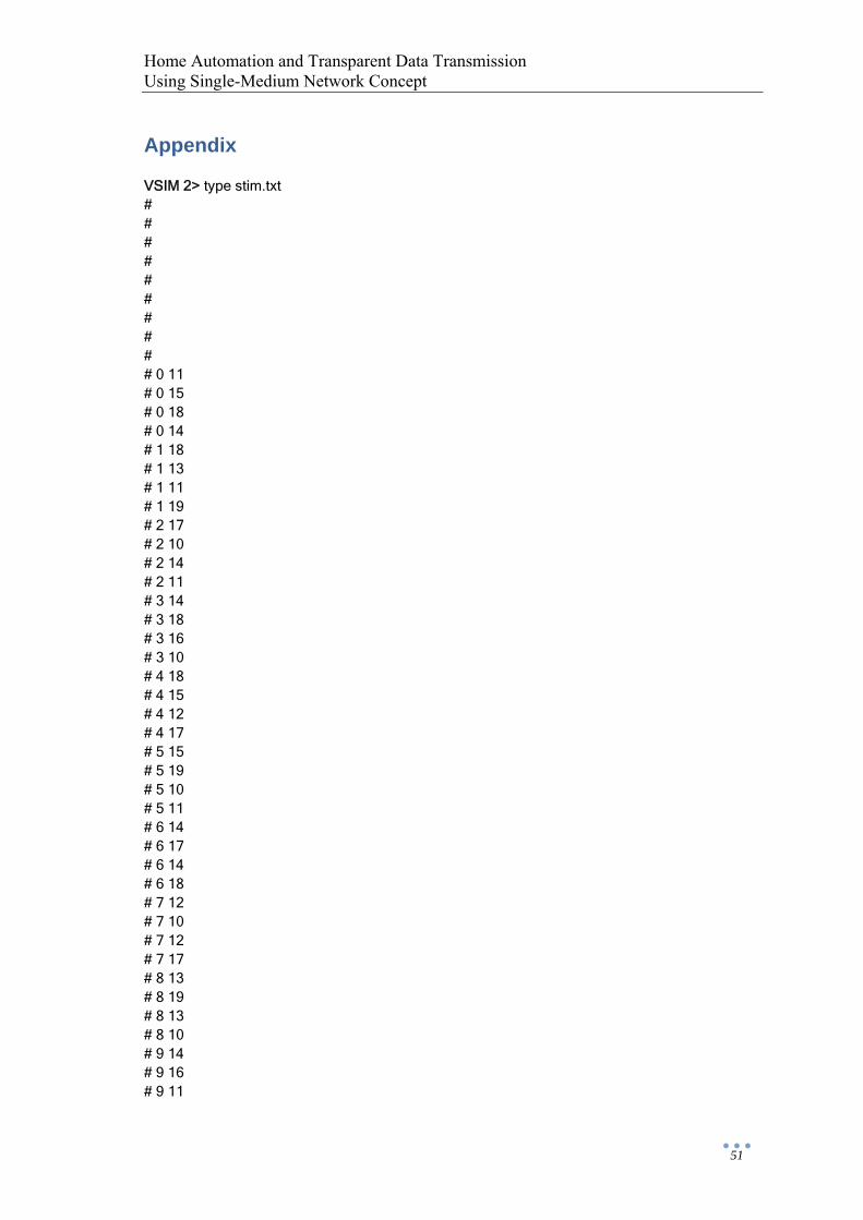
Home Automation and Transparent Data Transmission Using Single-Medium Network Concept
51
Appendix
VSIM 2> type stim.txt # # # # # # # # # # 0 11 # 0 15 # 0 18 # 0 14 # 1 18 # 1 13 # 1 11 # 1 19 # 2 17 # 2 10 # 2 14 # 2 11 # 3 14 # 3 18 # 3 16 # 3 10 # 4 18 # 4 15 # 4 12 # 4 17 # 5 15 # 5 19 # 5 10 # 5 11 # 6 14 # 6 17 # 6 14 # 6 18 # 7 12 # 7 10 # 7 12 # 7 17 # 8 13 # 8 19 # 8 13 # 8 10 # 9 14 # 9 16 # 9 11
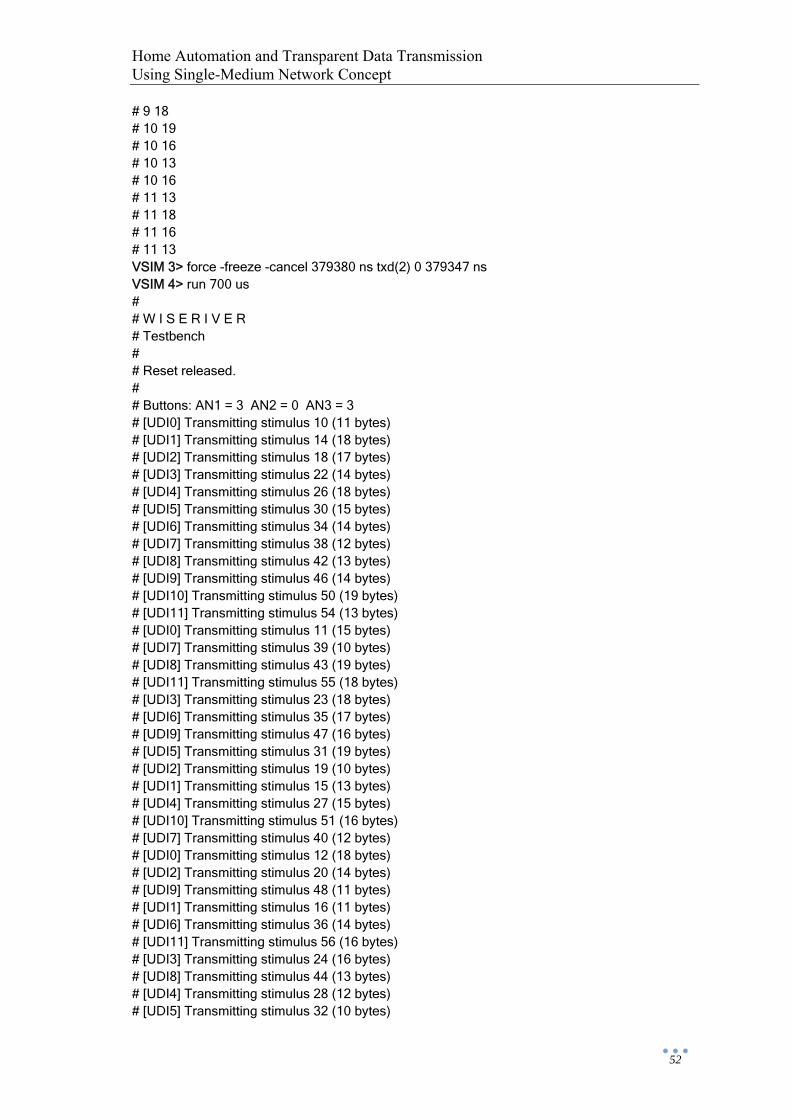
Home Automation and Transparent Data Transmission Using Single-Medium Network Concept
52
# 9 18 # 10 19 # 10 16 # 10 13 # 10 16 # 11 13 # 11 18 # 11 16 # 11 13 VSIM 3> force -freeze -cancel 379380 ns txd(2) 0 379347 ns VSIM 4> run 700 us # # W I S E R I V E R # Testbench # # Reset released. # # Buttons: AN1 = 3 AN2 = 0 AN3 = 3 # [UDI0] Transmitting stimulus 10 (11 bytes) # [UDI1] Transmitting stimulus 14 (18 bytes) # [UDI2] Transmitting stimulus 18 (17 bytes) # [UDI3] Transmitting stimulus 22 (14 bytes) # [UDI4] Transmitting stimulus 26 (18 bytes) # [UDI5] Transmitting stimulus 30 (15 bytes) # [UDI6] Transmitting stimulus 34 (14 bytes) # [UDI7] Transmitting stimulus 38 (12 bytes) # [UDI8] Transmitting stimulus 42 (13 bytes) # [UDI9] Transmitting stimulus 46 (14 bytes) # [UDI10] Transmitting stimulus 50 (19 bytes) # [UDI11] Transmitting stimulus 54 (13 bytes) # [UDI0] Transmitting stimulus 11 (15 bytes) # [UDI7] Transmitting stimulus 39 (10 bytes) # [UDI8] Transmitting stimulus 43 (19 bytes) # [UDI11] Transmitting stimulus 55 (18 bytes) # [UDI3] Transmitting stimulus 23 (18 bytes) # [UDI6] Transmitting stimulus 35 (17 bytes) # [UDI9] Transmitting stimulus 47 (16 bytes) # [UDI5] Transmitting stimulus 31 (19 bytes) # [UDI2] Transmitting stimulus 19 (10 bytes) # [UDI1] Transmitting stimulus 15 (13 bytes) # [UDI4] Transmitting stimulus 27 (15 bytes) # [UDI10] Transmitting stimulus 51 (16 bytes) # [UDI7] Transmitting stimulus 40 (12 bytes) # [UDI0] Transmitting stimulus 12 (18 bytes) # [UDI2] Transmitting stimulus 20 (14 bytes) # [UDI9] Transmitting stimulus 48 (11 bytes) # [UDI1] Transmitting stimulus 16 (11 bytes) # [UDI6] Transmitting stimulus 36 (14 bytes) # [UDI11] Transmitting stimulus 56 (16 bytes) # [UDI3] Transmitting stimulus 24 (16 bytes) # [UDI8] Transmitting stimulus 44 (13 bytes) # [UDI4] Transmitting stimulus 28 (12 bytes) # [UDI5] Transmitting stimulus 32 (10 bytes)
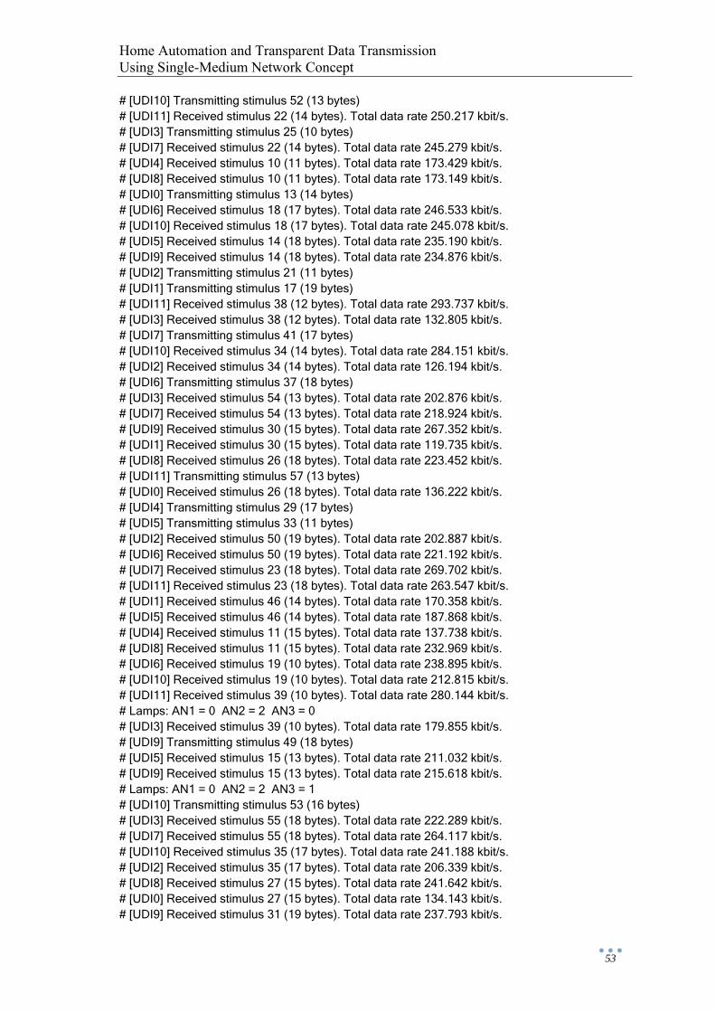
Home Automation and Transparent Data Transmission Using Single-Medium Network Concept
53
# [UDI10] Transmitting stimulus 52 (13 bytes) # [UDI11] Received stimulus 22 (14 bytes). Total data rate 250.217 kbit/s. # [UDI3] Transmitting stimulus 25 (10 bytes) # [UDI7] Received stimulus 22 (14 bytes). Total data rate 245.279 kbit/s. # [UDI4] Received stimulus 10 (11 bytes). Total data rate 173.429 kbit/s. # [UDI8] Received stimulus 10 (11 bytes). Total data rate 173.149 kbit/s. # [UDI0] Transmitting stimulus 13 (14 bytes) # [UDI6] Received stimulus 18 (17 bytes). Total data rate 246.533 kbit/s. # [UDI10] Received stimulus 18 (17 bytes). Total data rate 245.078 kbit/s. # [UDI5] Received stimulus 14 (18 bytes). Total data rate 235.190 kbit/s. # [UDI9] Received stimulus 14 (18 bytes). Total data rate 234.876 kbit/s. # [UDI2] Transmitting stimulus 21 (11 bytes) # [UDI1] Transmitting stimulus 17 (19 bytes) # [UDI11] Received stimulus 38 (12 bytes). Total data rate 293.737 kbit/s. # [UDI3] Received stimulus 38 (12 bytes). Total data rate 132.805 kbit/s. # [UDI7] Transmitting stimulus 41 (17 bytes) # [UDI10] Received stimulus 34 (14 bytes). Total data rate 284.151 kbit/s. # [UDI2] Received stimulus 34 (14 bytes). Total data rate 126.194 kbit/s. # [UDI6] Transmitting stimulus 37 (18 bytes) # [UDI3] Received stimulus 54 (13 bytes). Total data rate 202.876 kbit/s. # [UDI7] Received stimulus 54 (13 bytes). Total data rate 218.924 kbit/s. # [UDI9] Received stimulus 30 (15 bytes). Total data rate 267.352 kbit/s. # [UDI1] Received stimulus 30 (15 bytes). Total data rate 119.735 kbit/s. # [UDI8] Received stimulus 26 (18 bytes). Total data rate 223.452 kbit/s. # [UDI11] Transmitting stimulus 57 (13 bytes) # [UDI0] Received stimulus 26 (18 bytes). Total data rate 136.222 kbit/s. # [UDI4] Transmitting stimulus 29 (17 bytes) # [UDI5] Transmitting stimulus 33 (11 bytes) # [UDI2] Received stimulus 50 (19 bytes). Total data rate 202.887 kbit/s. # [UDI6] Received stimulus 50 (19 bytes). Total data rate 221.192 kbit/s. # [UDI7] Received stimulus 23 (18 bytes). Total data rate 269.702 kbit/s. # [UDI11] Received stimulus 23 (18 bytes). Total data rate 263.547 kbit/s. # [UDI1] Received stimulus 46 (14 bytes). Total data rate 170.358 kbit/s. # [UDI5] Received stimulus 46 (14 bytes). Total data rate 187.868 kbit/s. # [UDI4] Received stimulus 11 (15 bytes). Total data rate 137.738 kbit/s. # [UDI8] Received stimulus 11 (15 bytes). Total data rate 232.969 kbit/s. # [UDI6] Received stimulus 19 (10 bytes). Total data rate 238.895 kbit/s. # [UDI10] Received stimulus 19 (10 bytes). Total data rate 212.815 kbit/s. # [UDI11] Received stimulus 39 (10 bytes). Total data rate 280.144 kbit/s. # Lamps: AN1 = 0 AN2 = 2 AN3 = 0 # [UDI3] Received stimulus 39 (10 bytes). Total data rate 179.855 kbit/s. # [UDI9] Transmitting stimulus 49 (18 bytes) # [UDI5] Received stimulus 15 (13 bytes). Total data rate 211.032 kbit/s. # [UDI9] Received stimulus 15 (13 bytes). Total data rate 215.618 kbit/s. # Lamps: AN1 = 0 AN2 = 2 AN3 = 1 # [UDI10] Transmitting stimulus 53 (16 bytes) # [UDI3] Received stimulus 55 (18 bytes). Total data rate 222.289 kbit/s. # [UDI7] Received stimulus 55 (18 bytes). Total data rate 264.117 kbit/s. # [UDI10] Received stimulus 35 (17 bytes). Total data rate 241.188 kbit/s. # [UDI2] Received stimulus 35 (17 bytes). Total data rate 206.339 kbit/s. # [UDI8] Received stimulus 27 (15 bytes). Total data rate 241.642 kbit/s. # [UDI0] Received stimulus 27 (15 bytes). Total data rate 134.143 kbit/s. # [UDI9] Received stimulus 31 (19 bytes). Total data rate 237.793 kbit/s.

Home Automation and Transparent Data Transmission Using Single-Medium Network Concept
54
# [UDI1] Received stimulus 31 (19 bytes). Total data rate 174.425 kbit/s. # [UDI7] Received stimulus 24 (16 bytes). Total data rate 284.954 kbit/s. # [UDI11] Received stimulus 24 (16 bytes). Total data rate 252.398 kbit/s. # [UDI2] Received stimulus 51 (16 bytes). Total data rate 231.396 kbit/s. # [UDI6] Received stimulus 51 (16 bytes). Total data rate 217.294 kbit/s. # [UDI0] Received stimulus 42 (13 bytes). Total data rate 155.957 kbit/s. # [UDI4] Received stimulus 42 (13 bytes). Total data rate 132.179 kbit/s. # [UDI11] Received stimulus 40 (12 bytes). Total data rate 266.536 kbit/s. # [UDI3] Received stimulus 40 (12 bytes). Total data rate 210.020 kbit/s. # [UDI6] Received stimulus 20 (14 bytes). Total data rate 234.543 kbit/s. # [UDI10] Received stimulus 20 (14 bytes). Total data rate 222.128 kbit/s. # [UDI1] Received stimulus 47 (16 bytes). Total data rate 196.269 kbit/s. # [UDI5] Received stimulus 47 (16 bytes). Total data rate 187.010 kbit/s. # [UDI8] Transmitting stimulus 45 (10 bytes) # [UDI3] Received stimulus 56 (16 bytes). Total data rate 232.215 kbit/s. # [UDI7] Received stimulus 56 (16 bytes). Total data rate 272.270 kbit/s. # [UDI4] Received stimulus 12 (18 bytes). Total data rate 157.850 kbit/s. # [UDI8] Received stimulus 12 (18 bytes). Total data rate 213.175 kbit/s. # [UDI5] Received stimulus 16 (11 bytes). Total data rate 198.600 kbit/s. # [UDI9] Received stimulus 16 (11 bytes). Total data rate 209.575 kbit/s. # [UDI10] Received stimulus 36 (14 bytes). Total data rate 236.883 kbit/s. # [UDI2] Received stimulus 36 (14 bytes). Total data rate 219.243 kbit/s. # [UDI7] Received stimulus 25 (10 bytes). Total data rate 280.054 kbit/s. # [UDI11] Received stimulus 25 (10 bytes). Total data rate 245.314 kbit/s. # [UDI9] Received stimulus 32 (10 bytes). Total data rate 216.432 kbit/s. # [UDI1] Received stimulus 32 (10 bytes). Total data rate 185.373 kbit/s. # [UDI2] Received stimulus 52 (13 bytes). Total data rate 231.543 kbit/s. # [UDI6] Received stimulus 52 (13 bytes). Total data rate 221.527 kbit/s. # [UDI8] Received stimulus 28 (12 bytes). Total data rate 218.300 kbit/s. # [UDI0] Received stimulus 28 (12 bytes). Total data rate 141.623 kbit/s. # [UDI11] Received stimulus 41 (17 bytes). Total data rate 261.575 kbit/s. # [UDI3] Received stimulus 41 (17 bytes). Total data rate 234.142 kbit/s. # Lamps: AN1 = 2 AN2 = 2 AN3 = 1 # [UDI6] Received stimulus 21 (11 bytes). Total data rate 230.245 kbit/s. # [UDI10] Received stimulus 21 (11 bytes). Total data rate 223.285 kbit/s. # [UDI1] Received stimulus 48 (11 bytes). Total data rate 194.881 kbit/s. # [UDI5] Received stimulus 48 (11 bytes). Total data rate 190.251 kbit/s. # [UDI3] Received stimulus 57 (13 bytes). Total data rate 246.170 kbit/s. # [UDI7] Received stimulus 57 (13 bytes). Total data rate 261.635 kbit/s. # Lamps: AN1 = 2 AN2 = 3 AN3 = 1 # [UDI0] Received stimulus 43 (19 bytes). Total data rate 160.454 kbit/s. # [UDI4] Received stimulus 43 (19 bytes). Total data rate 158.337 kbit/s. # [UDI10] Received stimulus 37 (18 bytes). Total data rate 237.461 kbit/s. # [UDI2] Received stimulus 37 (18 bytes). Error in byte 11. Total data rate 228.332 bit/s. # [UDI5] Received stimulus 17 (19 bytes). Total data rate 205.448 kbit/s. # [UDI9] Received stimulus 17 (19 bytes). Total data rate 211.447 kbit/s. # [UDI2] Received stimulus 53 (16 bytes). Total data rate 240.104 kbit/s. # [UDI6] Received stimulus 53 (16 bytes). Total data rate 219.265 kbit/s. # [UDI9] Received stimulus 33 (11 bytes). Total data rate 217.790 kbit/s. # [UDI4] Received stimulus 13 (14 bytes). Total data rate 168.942 kbit/s. # [UDI8] Received stimulus 13 (14 bytes). Total data rate 193.308 kbit/s. # [UDI1] Received stimulus 33 (11 bytes). Total data rate 179.618 kbit/s. # [UDI1] Received stimulus 49 (18 bytes). Total data rate 193.063 kbit/s.
Home Automation and Transparent Data Transmission Using Single-Medium Network Concept
55
# [UDI5] Received stimulus 49 (18 bytes). Total data rate 203.189 kbit/s. # [UDI8] Received stimulus 29 (17 bytes). Total data rate 201.132 kbit/s. # [UDI0] Received stimulus 29 (17 bytes). Total data rate 157.068 kbit/s. # [UDI0] Received stimulus 44 (13 bytes). Total data rate 165.325 kbit/s. # [UDI4] Received stimulus 44 (13 bytes). Total data rate 159.120 kbit/s. # [UDI0] Received stimulus 45 (10 bytes). Total data rate 170.092 kbit/s. # [UDI4] Received stimulus 45 (10 bytes). Total data rate 164.253 kbit/s.