Embed Size (px)
Citation preview
Dell Force10
S4810 System
Quick Start Guide
Regulatory Model: S4810P


Dell Force10
S4810 System
Quick Start Guide
Regulatory Model: S4810P
Notes, Cautions, and Warnings NOTE: A NOTE indicates important information that helps you make better use
of your computer.
CAUTION: A CAUTION indicates potential damage to hardware or loss of data if instructions are not followed.
WARNING: A WARNING indicates a potential for property damage, personal injury, or death.
If you purchased a Dell n Series computer, any references in this publication to Microsoft Windows operating systems are not applicable.
____________________
Information in this publication is subject to change without notice.© 2011 Dell Inc. All rights reserved.
Reproduction of these materials in any manner whatsoever without the written permission of Dell Inc. is strictly forbidden.
Trademarks used in this text: Dell™, the DELL logo, Dell Precision™, OptiPlex™, Latitude™, PowerEdge™, PowerVault™, PowerConnect™, OpenManage™, EqualLogic™, KACE™, FlexAddress™ and Vostro™ are trademarks of Dell Inc. Intel®, Pentium®, Xeon®, Core™ and Celeron® are registered trademarks of Intel Corporation in the U.S. and other countries. AMD® is a registered trademark and AMD Opteron™, AMD Phenom™, and AMD Sempron™ are trademarks of Advanced Micro Devices, Inc. Microsoft®, Windows®, Windows Server®, MS-DOS® and Windows Vista® are either trademarks or registered trademarks of Microsoft Corporation in the United States and/or other countries. Red Hat Enterprise Linux® and Enterprise Linux® are registered trademarks of Red Hat, Inc. in the United States and/or other countries. Novell® is a registered trademark and SUSE ™ is a trademark of Novell Inc. in the United States and other countries. Oracle® is a registered trademark of Oracle Corporation and/or its affiliates. Citrix®, Xen®, XenServer® and XenMotion® are either registered trademarks or trademarks of Citrix Systems, Inc. in the United States and/or other countries. VMware®, Virtual SMP®, vMotion®, vCenter®, and vSphere® are registered trademarks or trademarks of VMWare, Inc. in the United States or other countries.
Other trademarks and trade names may be used in this publication to refer to either the entities claiming the marks and names or their products. Dell Inc. disclaims any proprietary interest in trademarks and trade names other than its own.
Regulatory Model: S4810P
2011 - 9 P/N 0V80HV Rev. A00
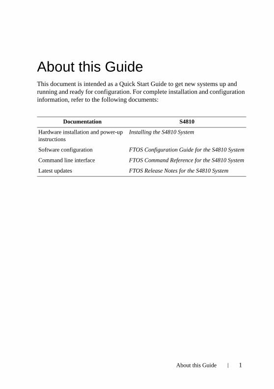
About this GuideThis document is intended as a Quick Start Guide to get new systems up and running and ready for configuration. For complete installation and configuration information, refer to the following documents:
Documentation S4810
Hardware installation and power-up instructions
Installing the S4810 System
Software configuration FTOS Configuration Guide for the S4810 System
Command line interface FTOS Command Reference for the S4810 System
Latest updates FTOS Release Notes for the S4810 System
About this Guide 1

2 About this Guide
1Installing the HardwareThis guide assumes all site preparation has been performed before installing the chassis.
Installing the S4810 Chassis in a Rack or CabinetTo install the S4810 system, Dell Force10 recommends that you complete the installation procedures in the order presented below.
Always handle the system and its components with care. Avoid dropping the S4810 chassis or its field replaceable units.
For proper ventilation, position the S4810 chassis in an equipment rack (or cabinet) with a minimum of five inches (12.7 cm) of clearance around exhaust vents. The acceptable ambient temperature ranges are listed in the Environmental Parameters section.
CAUTION: Always wear an ESD-preventive wrist or heel ground strap when handling the S4810 and its components. As with all electrical devices of this type, take all necessary safety precautions to prevent injury when installing this system. Electrostatic discharge (ESD) damage can occur if components are mishandled.
Attaching Mounting Brackets
The S4810 is shipped with mounting brackets (rack ears) and required screws for rack or cabinet installation. The brackets are enclosed in a package with the chassis.
Step Task
1 Take the brackets and screws out of their packaging.
Installing the Hardware 3
Install chassis into 2-post rack or cabinet
Attach a Ground Cable
The S4810 is shipped with 1 M4x0.7 screw for attaching a ground cable to the chassis. The cable itself is not included. Dell Force10 recommends a 6AWG one-hole lug, #10 hole size, 63" spacing (not included in shipping) to properly ground the chassis. The one-hole lug must be a UL recognized, crimp-type lug.
NOTE: The rack installation ears are not suitable for grounding.
CAUTION: Grounding conductors must be made of copper. Do not use aluminum conductors.
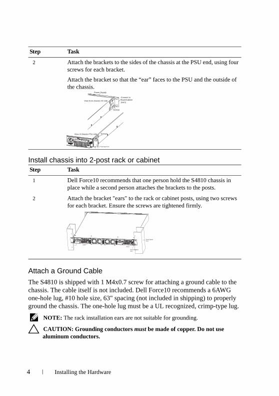
2 Attach the brackets to the sides of the chassis at the PSU end, using four screws for each bracket.
Attach the bracket so that the “ear” faces to the PSU and the outside of the chassis.
Step Task
1 Dell Force10 recommends that one person hold the S4810 chassis in place while a second person attaches the brackets to the posts.
2 Attach the bracket "ears" to the rack or cabinet posts, using two screws for each bracket. Ensure the screws are tightened firmly.
Step Task
View from chassis I/O side
View of chassis PSU side
Power Supply
Screws
Screws
Connect toRack/Cabinet(ears)
Connect to
PSU0
PSU1
Rack/CabinetPost
Rack MountingEars
4 Installing the Hardware
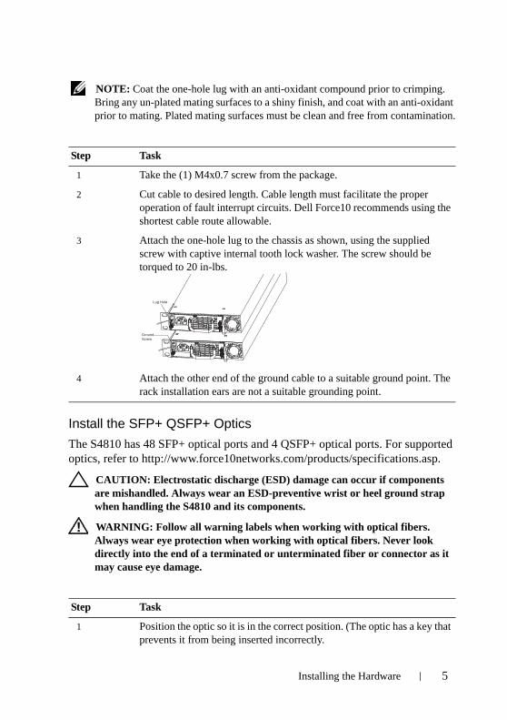
NOTE: Coat the one-hole lug with an anti-oxidant compound prior to crimping. Bring any un-plated mating surfaces to a shiny finish, and coat with an anti-oxidant prior to mating. Plated mating surfaces must be clean and free from contamination.
Install the SFP+ QSFP+ Optics
The S4810 has 48 SFP+ optical ports and 4 QSFP+ optical ports. For supported optics, refer to http://www.force10networks.com/products/specifications.asp.
CAUTION: Electrostatic discharge (ESD) damage can occur if components are mishandled. Always wear an ESD-preventive wrist or heel ground strap when handling the S4810 and its components.
WARNING: Follow all warning labels when working with optical fibers. Always wear eye protection when working with optical fibers. Never look directly into the end of a terminated or unterminated fiber or connector as it may cause eye damage.
Step Task
1 Take the (1) M4x0.7 screw from the package.
2 Cut cable to desired length. Cable length must facilitate the proper operation of fault interrupt circuits. Dell Force10 recommends using the shortest cable route allowable.
3 Attach the one-hole lug to the chassis as shown, using the supplied screw with captive internal tooth lock washer. The screw should be torqued to 20 in-lbs.
4 Attach the other end of the ground cable to a suitable ground point. The rack installation ears are not a suitable grounding point.
Step Task
1 Position the optic so it is in the correct position. (The optic has a key that prevents it from being inserted incorrectly.
Lug Hole
GroundScrew
Installing the Hardware 5
Splitting QSFP Ports to SFP+ Ports
The S4810 supports splitting a single 40G QSFP port into four 10G SFP+ ports using one of the supported breakout cables (refer to Installing the S4810 System or Release Notes for the S4810 System for a list of supported cables).
You must enter the stack-unit portmode command for the system to recognize the port type change. For example:
stack-unit stack-unit port number portmode quad
• stack-unit: Enter the stack member unit identifier of the stack member to reset. Range: 0-11
• number: Enter the port number of the 40G port to be split. Range: 0-31
Important Points
• Splitting a 40G port into 4x10G port is supported only on a standalone unit.
• Split ports cannot be used as stack-link to stack an S4810.
• Split ports S4810 unit cannot be a part of any stacked system.
• The unit number with the split ports must be the default (stack-unit 0). This can be verified using the show system brief command. If the unit ID is different than 0, then it must be renumbered to 0 before ports are split, by entering in EXEC mode: stackunit id renumber 0
• The quad port must be in a default configuration before it can be split into 4x10G ports. The 40G port is lost in the running-configuration when the port is split, so be sure the port is also removed from other L2/L3 feature configurations.
• The system must be reloaded after issuing the CLI for the change to take effect.
Supply Power and Power Up the SystemSupply power to the S4810 after the chassis is mounted in a rack or cabinet.
2 Insert the optic into the port until it gently snaps into place.
NOTE: Both rows of QSFP+ ports require that the 40G optics be inserted with the tabs facing up.
Step Task
6 Installing the Hardware
Dell Force10 recommends re-inspecting your system prior to powering up. Verify that:
• The equipment is properly secured to the rack and properly grounded.
• The equipment rack is properly mounted and grounded.
• The ambient temperature around the unit (which may be higher than the room temperature) is within the limits specified for the S4810.
• There is sufficient airflow around the unit.
• The input circuits are correctly sized for the loads and that sufficient over-current protection devices are used.
• All protective covers are in place.
NOTE: A US AC power cable is included in the shipping container for powering up an AC power supply. All other power cables must be ordered separately.
CAUTION: Electrostatic discharge (ESD) damage can occur if components are mishandled. Always wear an ESD-preventive wrist or heel ground strap when handling the S4810 and its components.
When the chassis powers up, the fans come on at high speed. The fan speed slows as the system boots up.
The PWR LED blinks until the boot-up sequence is complete. When the boot up is complete the PWD LED is steadily lit.
AC Power
CAUTION: Ensure that the Power Supply Unit is installed correctly. The AC power connector must be on the left side of the PSU, and the status LED is at the top of the PSU when the unit is correctly installed.
Connect the plug to each AC power connector, making sure that the power cord is secure.
As soon as the cable is connected between the S4810 and the power source, the chassis is powered-up; there is no on/off switch.
DC Power
Connect the plug to each DC receptacle, making sure that the power cord is secure.
As soon as the cable is connected between the S4810 and the power source, the
Installing the Hardware 7
chassis is powered-up; there is no on/off switch.
Fans
The S4810 comes from the factory with 1 power supply and 2 fan modules installed in the chassis. Both the fan module and the integrated fan-power supply are hot-swappable if a second (redundant) power supply is installed and running.
NOTE: Both slots must have operating fan units to run the system. If a module is not installed in each slot (either as part of the PSU or as an independent fan module), the system will shut down in 1 minute.
The S4810 supports two airflow direction options. Only a single direction can be used in a chassis; do not mix fan flow types in a chassis. The system will shutdown in 1 minute, if the airflow directions are mismatched.
• Normal is airflow from I/O panel to power supply.
• Reversed is airflow from power supply to I/O panel.
There are environmental factors that could decrease the amount of time required between fan replacements. Check these environmental factors regularly. Any unusual environmental circumstance at the site that causes an increase in temperature and/or particulate matter in the air might affect performance (for example, new equipment installation).
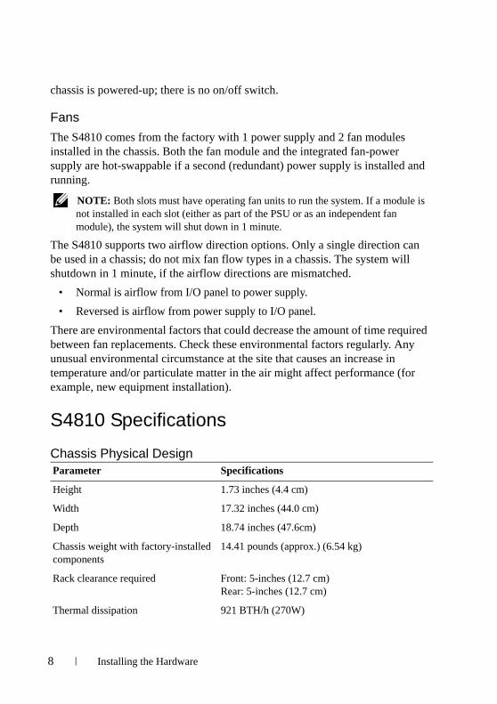
S4810 Specifications
Chassis Physical DesignParameter Specifications
Height 1.73 inches (4.4 cm)
Width 17.32 inches (44.0 cm)
Depth 18.74 inches (47.6cm)
Chassis weight with factory-installed components
14.41 pounds (approx.) (6.54 kg)
Rack clearance required Front: 5-inches (12.7 cm) Rear: 5-inches (12.7 cm)
Thermal dissipation 921 BTH/h (270W)
8 Installing the Hardware
Environmental Parameters
AC Power Requirements
DC Power Requirements
Power Consumption 230 Watts (nominal)
270 Watts (maximum)
Parameter Specifications
Temperature 32° to 104°F (0° to 40°C)
-40° to 158°F (-20° to 70°C)
Maximum altitude No performance degradation to 10,000 feet (3,048 meters)
Relative humidity 10 to 85% non-condensing
Shock MIL-STD-810
Parameter Specifications
Nominal Input Voltage 100 to 240 VAC, 47-63 Hz
Maximum AC Power Supply Input Current
4.20 A @ 100VAC
1.70 A @ 240 VAC
Maximum System Power Input 350 W
Parameter Specifications
Nominal Input Voltage 36 to 72 VDC
Maximum Power Supply Input Current
2.8A @ 36 VDC1.85 A @ 72 VDC
Maximum System Power Input 360 W
Parameter Specifications
Installing the Hardware 9
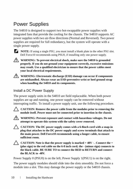
Power SuppliesThe S4810 is designed to support two hot-swappable power supplies with integrated fans that provide the cooling for the chassis. The S4810 supports AC power supplies with two air-flow directions (Normal and Reversed). Two power supplies are required for full redundancy, but the system will operate with a single power supply.
NOTE: If using a single PSU, you must install a blank plate in the other PSU slot. Dell Force10 recommends using PSU0, if installing only one power supply.
WARNING: To prevent electrical shock, make sure the S4810 is grounded properly. If you do not ground your equipment correctly, excessive emissions may result. Use a qualified electrician to ensure that the power cables meet your local electrical requirements.
WARNING: Electrostatic discharge (ESD) damage can occur if components are mishandled. Always wear an ESD-preventive wrist or heel ground strap when handling the S4810 and its components.
Install a DC Power Supply
The power supply units in the S4810 are field replaceable. When both power supplies are up and running, one power supply can be removed without interrupting traffic. To install a power supply unit, use the following procedure.
CAUTION: Remove the power cable from the modules prior to removing the module itself. Power must not be connected prior to insertion in the chassis.
WARNING: Prevent exposure and contact with hazardous voltages. Do not attempt to operate this system with the safety cover removed.
CAUTION: The DC power supply comes with a 6-8inch cord with a snap-in plug that attaches to the DC power supply and screw terminals that attach to the main power. Dell Force10 recommends using a longer cable, to ensure sufficient room.
CAUTION: Note is that the power supply is marked + 48V - . Connect the + (plus sign) to the red cable on the 6-8 inch cord; the - (minus sign) connects to the black cable. BE SURE TO to connect the RED to RETURN and connect the BLACK to -48V.
Power Supply 0 (PSU0) is on the left; Power Supply 1(PSU1) is on the right.
The power supply modules should slide into the slots smoothly. Do not force a module into a slot. This may damage the power supply or the S4810 chassis.
10 Installing the Hardware
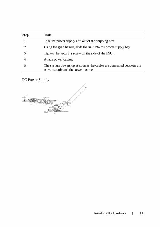
DC Power Supply
Step Task
1 Take the power supply unit out of the shipping box.
2 Using the grab handle, slide the unit into the power supply bay.
3 Tighten the securing screw on the side of the PSU.
4 Attach power cables.
5 The system powers up as soon as the cables are connected between the power supply and the power source.
PSU0
PSU1
Fan Modules
Cable Connector
Grab Handle
Installing the Hardware 11

12 Installing the Hardware
2Installing the Software
Navigating CLI ModesThe FTOS prompt changes to indicate the CLI mode. You must move linearly through the command modes, with the exception of the end command which takes you directly to EXEC Privilege mode; the exit command moves you up one command mode level.
Console Access NOTE: Before starting this procedure, be sure you have a terminal emulation
program already installed on your PC.
The RS-232 console port is labeled on the S4810 chassis. It is in the upper right-hand side, as you face the I/O side of the chassis.
Step Task
1 Install an RJ-45 copper cable into the console port. Use a rollover cable to connect the S4810 console port to a terminal server.
2 Connect the other end of the cable to the DTE terminal server.
3 Default terminal settings on the console port are set as follows:
9600 baud rate
No parity
8 data bits
1 stop bit
No flow control
RJ-45Console Port
Installing the Software 13
Accessing the RJ-45 Console Port with a DB-9 Adapter
You can connect to the console using an RJ-45 to DB-9 adapter along with the RJ-45 rollover cable if the DTE has a DB-9 interface. Table 2-1 lists the pin assignments.
Default ConfigurationA version of FTOS is pre-loaded onto the chassis, however the system is not configured when you power up for the first time (except for the default host name, which is Force10). You must configure the system using the CLI.
Configure Layer 2 (Data Link) ModeUse the switchport command in INTERFACE mode to enable Layer 2 data transmissions through an individual interface. The user cannot configure switching or Layer 2 protocols such as spanning tree protocol on an interface unless the interface has been set to Layer 2 mode.
Table 2-1. Pin Assignments Between the Console and a DTE Terminal Server
Console Port RJ-45 to RJ-45 Rollover Cable RJ-45 to DB-9 Adapter
Terminal Server Device
Signal RJ-45 Pinout RJ-45 Pinout DB-9 Pin Signal
RTS 1 8 8 CTS
NC 2 7 6 DSR
TxD 3 6 2 RxD
GND 4 5 5 GND
GND 5 4 5 GND
RxD 6 3 3 TxD
NC 7 2 4 DTR
CTS 8 1 7 RTS
Step Task Command Syntax Command Mode
1 Enable the interface. no shutdown INTERFACE
14 Installing the Software
To view the interfaces in Layer 2 mode, use the show interfaces switchport command in the EXEC mode.
Configure a Host NameThe host name appears in the prompt. The default host name is force10.
• Host names must start with a letter and end with a letter or digit.
• Characters within the string can be letters, digits, and hyphens.
Access the System RemotelyYou can configure the system to be accessed remotely by Telnet. The S4810 has a dedicated management port and a management routing table that is separate from the IP routing table.
Configure the Management Port IP Address
Assign IP addresses to the management ports in order to access the system remotely.
2 Place the interface in Layer 2 (switching) mode.
switchport INTERFACE
Task Command Syntax Command Mode
Create a new host name. hostname name CONFIGURATION
Step Task
1 Configure an IP address for the management port.
2 Configure a management route with a default gateway.
3 Configure a username and password.
Step Task Command Syntax Command Mode
Installing the Software 15
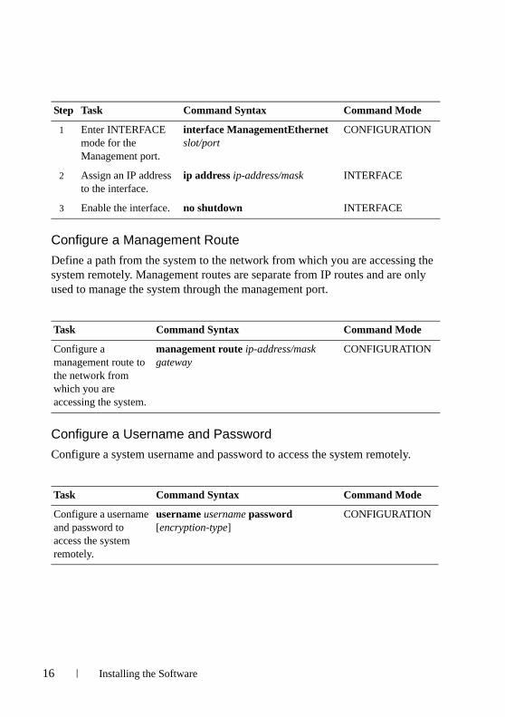
Configure a Management Route
Define a path from the system to the network from which you are accessing the system remotely. Management routes are separate from IP routes and are only used to manage the system through the management port.
Configure a Username and Password
Configure a system username and password to access the system remotely.
Step Task Command Syntax Command Mode
1 Enter INTERFACE mode for the Management port.
interface ManagementEthernet slot/port
CONFIGURATION
2 Assign an IP address to the interface.
ip address ip-address/mask INTERFACE
3 Enable the interface. no shutdown INTERFACE
Task Command Syntax Command Mode
Configure a management route to the network from which you are accessing the system.
management route ip-address/mask gateway
CONFIGURATION
Task Command Syntax Command Mode
Configure a username and password to access the system remotely.
username username password [encryption-type]
CONFIGURATION
16 Installing the Software
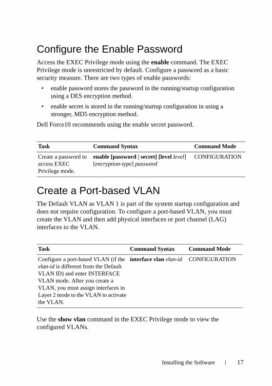
Configure the Enable PasswordAccess the EXEC Privilege mode using the enable command. The EXEC Privilege mode is unrestricted by default. Configure a password as a basic security measure. There are two types of enable passwords:
• enable password stores the password in the running/startup configuration using a DES encryption method.
• enable secret is stored in the running/startup configuration in using a stronger, MD5 encryption method.
Dell Force10 recommends using the enable secret password.
Create a Port-based VLANThe Default VLAN as VLAN 1 is part of the system startup configuration and does not require configuration. To configure a port-based VLAN, you must create the VLAN and then add physical interfaces or port channel (LAG) interfaces to the VLAN.
Use the show vlan command in the EXEC Privilege mode to view the configured VLANs.
Task Command Syntax Command Mode
Create a password to access EXEC Privilege mode.
enable [password | secret] [level level] [encryption-type] password
CONFIGURATION
Task Command Syntax Command Mode
Configure a port-based VLAN (if the vlan-id is different from the Default VLAN ID) and enter INTERFACE VLAN mode. After you create a VLAN, you must assign interfaces in Layer 2 mode to the VLAN to activate the VLAN.
interface vlan vlan-id CONFIGURATION
Installing the Software 17
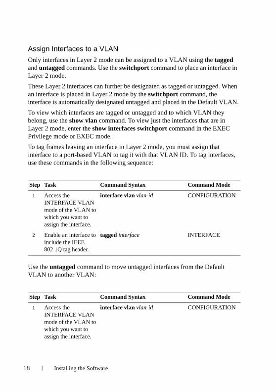
Assign Interfaces to a VLAN
Only interfaces in Layer 2 mode can be assigned to a VLAN using the tagged and untagged commands. Use the switchport command to place an interface in Layer 2 mode.
These Layer 2 interfaces can further be designated as tagged or untagged. When an interface is placed in Layer 2 mode by the switchport command, the interface is automatically designated untagged and placed in the Default VLAN.
To view which interfaces are tagged or untagged and to which VLAN they belong, use the show vlan command. To view just the interfaces that are in Layer 2 mode, enter the show interfaces switchport command in the EXEC Privilege mode or EXEC mode.
To tag frames leaving an interface in Layer 2 mode, you must assign that interface to a port-based VLAN to tag it with that VLAN ID. To tag interfaces, use these commands in the following sequence:
Use the untagged command to move untagged interfaces from the Default VLAN to another VLAN:
Step Task Command Syntax Command Mode
1 Access the INTERFACE VLAN mode of the VLAN to which you want to assign the interface.
interface vlan vlan-id CONFIGURATION
2 Enable an interface to include the IEEE 802.1Q tag header.
tagged interface INTERFACE
Step Task Command Syntax Command Mode
1 Access the INTERFACE VLAN mode of the VLAN to which you want to assign the interface.
interface vlan vlan-id CONFIGURATION
18 Installing the Software
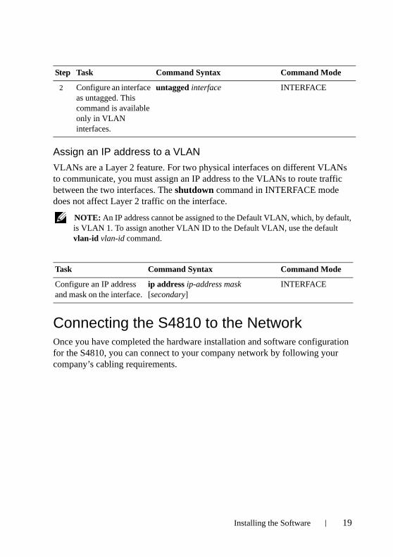
Assign an IP address to a VLAN
VLANs are a Layer 2 feature. For two physical interfaces on different VLANs to communicate, you must assign an IP address to the VLANs to route traffic between the two interfaces. The shutdown command in INTERFACE mode does not affect Layer 2 traffic on the interface.
NOTE: An IP address cannot be assigned to the Default VLAN, which, by default, is VLAN 1. To assign another VLAN ID to the Default VLAN, use the default vlan-id vlan-id command.
Connecting the S4810 to the NetworkOnce you have completed the hardware installation and software configuration for the S4810, you can connect to your company network by following your company’s cabling requirements.
2 Configure an interface as untagged. This command is available only in VLAN interfaces.
untagged interface INTERFACE
Task Command Syntax Command Mode
Configure an IP address and mask on the interface.
ip address ip-address mask [secondary]
INTERFACE
Step Task Command Syntax Command Mode
Installing the Software 19

20 Installing the Software


www.del l .com | support .del l .com
Printed in the U.S.A.