Embed Size (px)
Citation preview

ALESIS
Studio 24 Reference Manual

Contents
STUDIO 24 REFERENCE MANUAL 1
ContentsImportant Safety Instructions ................................................................................5
Safety symbols used in this product ........................................................................................... 5Please follow these precautions when using this product:..................................................... 5Instructions de Sécurité Importantes (French) .......................................................................... 7Symboles utilisés dans ce produit ............................................................................................. 7Veuillez suivre ces précautions lors de l’utilisation de l’appareil: ........................................ 7Beim Benutzen dieses Produktes beachten Sie bitte die folgendenSicherheitshinweise: (German)..................................................................................................... 9CE Declaration of Conformity...................................................................................................... 10
Introduction .............................................................................................................. 11How to use this manual................................................................................................................. 11
For beginners .................................................................................................................... 11For the experienced: a quick overview ....................................................................................... 13About the Studio 24........................................................................................................................ 15Basic Principles of Mixing & Multitrack Recording................................................................. 17
The stages of multitrack recording............................................................................... 18The different mixes and what they’re needed for .................................................................... 20
Multitrack Mix.................................................................................................................. 20Monitor (Control Room) Mix......................................................................................... 22Aux Sends and Returns: Effects .................................................................................... 24
Guided Tour ..............................................................................................................25Recorder Mix/Monitor Mix System............................................................................................ 25
Starting at the source: input and trim .......................................................................... 25The equalizer .................................................................................................................... 26Fader and assignment section ....................................................................................... 27Monitor 1/2 section......................................................................................................... 28
Aux Send/Return System ............................................................................................................. 29Aux sends .......................................................................................................................... 29Stereo Aux Returns.......................................................................................................... 29
Control Room System .................................................................................................................... 30Control Room source ...................................................................................................... 30Solo ..................................................................................................................................... 31Meters................................................................................................................................. 31
Hooking It Up ...........................................................................................................33Unpacking and Inspection ............................................................................................................ 33Power ................................................................................................................................................ 34
Avoiding ground loop noise.......................................................................................... 35Channel Inputs and Outputs ........................................................................................................ 36
Mic Inputs ......................................................................................................................... 36Line Inputs ........................................................................................................................ 37Tape Inputs ....................................................................................................................... 37Direct Outputs .................................................................................................................. 38Insert................................................................................................................................... 38
Master Inputs and Outputs........................................................................................................... 39Main Outputs.................................................................................................................... 39Main Inserts ...................................................................................................................... 39Group Outputs ................................................................................................................. 39Group Inserts .................................................................................................................... 40Control Room Outputs ................................................................................................... 402 Track Inputs ................................................................................................................... 40Stereo Aux Returns.......................................................................................................... 40MONITOR OUTS 1/2 and AUX SENDS 3/4............................................................. 40
Contents
2 STUDIO 24 REFERENCE MANUAL
Headphones ...................................................................................................................... 40Chart of Connections...................................................................................................................... 41
Connecting to an Unbalanced -10 dBV Multitrack Recorder .................................. 42Connecting to a 2-Track Mixdown Deck..................................................................... 43Connecting to a Control Room amplifier .................................................................... 44Connecting to a Headphone Amp................................................................................ 44Connecting to a Patchbay............................................................................................... 44
Effects and Signal Processing................................................................................45Connecting Aux Sends and Returns to Outboard Effects ....................................................... 45
Should you use one or two inputs to effects?............................................................. 46Using Effects .................................................................................................................................... 47Connecting Signal Processors to Insert Jacks ............................................................................ 49
Multitrack Recording Applications........................................................................51Recording ......................................................................................................................................... 51
Setting Levels.................................................................................................................... 51How to Record a Single Source to One Track............................................................. 53Recording Multiple Sources to One Track .................................................................. 54Recording Multiple Sources to Two Tracks (Stereo)................................................. 55Recording Tips ................................................................................................................. 57About Metering................................................................................................................ 57
Overdubbing.................................................................................................................................... 58Using MONITOR 1/2 to Monitor the Multitrack...................................................... 58Using the Channel Faders to Monitor the Multitrack............................................... 59Getting the Mix to the Headphones ............................................................................. 61Monitoring MIDI Virtual Tracks................................................................................... 62Bouncing Tracks............................................................................................................... 63
Playback/Mixdown........................................................................................................................ 65Getting the Mix to the 2-Track Deck ............................................................................ 65Mixdown Basics ............................................................................................................... 65Guidelines for a rough mix ............................................................................................ 66
Sound Reinforcement Applications .......................................................................69Creating a mono house mix .......................................................................................................... 69Subgrouping with the Group Faders .......................................................................................... 69
Stage Monitor Mix ........................................................................................................... 70Alternate uses for the Monitor 1/2 section: Stereo recording during a live concert.......... 71
Using Monitor 1/2 to feed a cassette deck.................................................................. 72Using Monitor 1/2 as the PA mix during multitrack recording............................. 73
Video Production and Post-Production...................................................................................... 74
Description of Controls ...........................................................................................75Channel Input Controls ................................................................................................................. 75
Trim .................................................................................................................................... 75Fader/Monitor Source switch: ...................................................................................... 75CHAN/MON REVERSE ................................................................................................ 75DIRECT OUT SOURCE switch ..................................................................................... 76
Equalizer section ............................................................................................................................. 7675 Hz switch...................................................................................................................... 76HIGH and LOW............................................................................................................... 77MID EQ controls: LEVEL and FREQ............................................................................ 78
Auxiliary Send Section................................................................................................................... 79AUX 3 and AUX 4 Sends ................................................................................................ 79MONITOR 1/2 LEVEL and PAN (Channels 1 - 8).................................................... 79MONITOR 1/2 LEVEL and BAL.................................................................................. 79(Stereo Channels 9 - 16)................................................................................................... 79
Channel Output Section ................................................................................................................ 80Channel PAN (Channels 1 - 8) ...................................................................................... 80Channel BALance (Stereo Channels) ........................................................................... 80

Contents
STUDIO 24 REFERENCE MANUAL 3
MUTE ................................................................................................................................. 80PEAK LED......................................................................................................................... 80-20 dB (Signal Present) LED........................................................................................... 81SOLO.................................................................................................................................. 81Group Assign Switch: GRP............................................................................................ 81L/R Switch ........................................................................................................................ 81Channel Fader .................................................................................................................. 82
Stereo Aux Return Section (A and B) .......................................................................................... 82MON 1/2 ........................................................................................................................... 82LEVEL ................................................................................................................................ 82L/R Assign Switches....................................................................................................... 82
MASTER SECTION........................................................................................................................ 82Power and Phantom indicators..................................................................................... 82Headphone Level............................................................................................................. 83Headphone jack................................................................................................................ 83GRP Assign Switches ...................................................................................................... 83SOLO IN PLACE Switch ................................................................................................ 83
Monitor 1/2 Master ........................................................................................................................ 83LINK TO L/R switch ...................................................................................................... 83
Control Room/Solo Section.......................................................................................................... 85Solo Master Level............................................................................................................. 85Control Room Level and Source ................................................................................... 85Meters................................................................................................................................. 86Master L/R Fader ............................................................................................................ 86
Group Master Controls.................................................................................................................. 86LINK TO L/R switch ...................................................................................................... 86MONO switch .................................................................................................................. 87GRP 1 and 2 Master FADERS........................................................................................ 87L/R Master Fader ............................................................................................................ 87
Top Panel Inputs and Outputs ..................................................................................................... 88Main Outs.......................................................................................................................... 88Main Inserts ...................................................................................................................... 88
Back panel ........................................................................................................................................ 89POWER switch ................................................................................................................. 89Power cable ....................................................................................................................... 89PHANTOM Switch.......................................................................................................... 89Control Room Outs L and R .......................................................................................... 892 Track Tape In................................................................................................................. 90Main Outs.......................................................................................................................... 90GROUP OUTPUTS .......................................................................................................... 90STEREO AUX RETURNS ............................................................................................... 90AUX SENDS...................................................................................................................... 90MON 1/2 ........................................................................................................................... 90
Channel Input/Output Jacks (8) .................................................................................................. 91Direct Out .......................................................................................................................... 91Tape In ............................................................................................................................... 91Insert jack........................................................................................................................... 91Line In jack (Channels 1 - 8)........................................................................................... 91Line In jacks (Stereo Channels) ..................................................................................... 92Mic In jack (Channels 1 - 8 only)................................................................................... 92
Troubleshooting.......................................................................................................93Troubleshooting Index................................................................................................................... 93Maintenance/Service ..................................................................................................................... 94
Specifications ...........................................................................................................97Frequency Response....................................................................................................................... 97Connectors........................................................................................................................................ 97Levels ................................................................................................................................................ 97

Contents
4 STUDIO 24 REFERENCE MANUAL
Impedance........................................................................................................................................ 98Noise performance (typical) ......................................................................................................... 98Distortion (THD+N)....................................................................................................................... 98Power ................................................................................................................................................ 98Dimensional Drawings: ................................................................................................................. 100
Gain Diagram............................................................................................................ 101
Block Diagram.......................................................................................................... 102
Index.......................................................................................................................... 103

Important Safety Instructions
STUDIO 24 REFERENCE MANUAL 5
IMPORTANT SAFETYINSTRUCTIONS
SAFETY SYMBOLS USED IN THIS PRODUCT
This symbol alerts the user that there are important operating andmaintenance instructions in the literature accompanying this unit.
This symbol warns the user of uninsulated voltage within the unitthat can cause dangerous electric shocks.
PLEASE FOLLOW THESE PRECAUTIONS WHEN USINGTHIS PRODUCT:
1. Read these instructions.
2. Keep these instructions.
3. Heed all warnings.
4. Follow all instructions.
5. Do not use this apparatus near water.
6. Clean only with a damp cloth. Do not spray any liquid cleaner onto thefaceplate, as this may damage the front panel controls or cause adangerous condition.
7. Install in accordance with the manufacturer's instructions.
8. Do not install near any heat sources such as radiators, heat registers,stoves, or other apparatus (including amplifiers) that produce heat.

Important Safety Instructions
6 STUDIO 24 REFERENCE MANUAL
9. Do not defeat the safety purpose of the polarized or grounding-type plug. Apolarized plug has two blades with one wider than the other. A grounding-typeplug has two blades and a third grounding prong. The wide blade or the thirdprong are provided for your safety. When the provided plug does not fit into youroutlet, consult an electrician for replacement of the obsolete outlet.
10. Protect the power cord from being walked on or pinched, particularly atplugs, convenience receptacles, and the point where they exit from theapparatus.
11. Use only attachments or accessories specified by the manufacturer.
12. Use only with a cart, stand, bracket, or table designed for use withprofessional audio or music equipment. In any installation, make sure thatinjury or damage will not result from cables pulling on the apparatus andits mounting. If a cart is used, use caution when moving the cart/apparatus combination to avoid injury from tip-over.
13. Unplug this apparatus during lightning storms or when unused for longperiods of time.
14. Refer all servicing to qualified service personnel. Servicing is required when the apparatus has been damaged in any way, such as when the power-supply cord or plug is damaged, liquid has been spilled or objects have fallen into the apparatus, the apparatus has been exposed to rain or moisture, does not operate normally, or has been dropped.
15. This unit produces heat when operated normally. Operate in a well-ventilated area.
16. This product, in combination with an amplifier and headphones orspeakers, may be capable of producing sound levels that could causepermanent hearing loss. Do not operate for a long period of time at a highvolume level or at a level that is uncomfortable. If you experience anyhearing loss or ringing in the ears, you should consult an audiologist.

Important Safety Instructions
STUDIO 24 REFERENCE MANUAL 7
INSTRUCTIONS DE SÉCURITÉ IMPORTANTES(FRENCH)
SYMBOLES UTILISÉS DANS CE PRODUIT
Ce symbole alèrte l’utilisateur qu’il existe des instructions defonctionnement et de maintenance dans la documentation jointeavec ce produit.
Ce symbole avertit l’utilisateur de la présence d’une tension nonisolée à l’intérieur de l’appareil pouvant engendrer des chocsélectriques.
VEUILLEZ SUIVRE CES PRÉCAUTIONS LORS DEL’UTILISATION DE L’APPAREIL:
1. Lisez ces instructions.
2. Gardez ces instructions.
3. Tenez compte de tous les avertissements.
4. Suivez toutes les instructions.
5. N’utilisez pas cet allareil à proximité de l’eau.
6. Ne nettoyez qu’avec un chiffon humide. Ne pas vaporiser de liquide nettoyantsur l’appareil, cela pourrait abîmer les contrôles de la face avant ou engendrer desconditions dangeureuses.
7. Installez selon les recommandations du constructeur.
8. Ne pas installer à proximilé de sources de chaleur comme radiateurs, cuisinière ouautre appareils (don’t les amplificateurs) produisant de la chaleur.
9. Ne pas enlever la prise de terre du cordon secteur. Une prise murale avec terredeux broches et une troisièrme reliée à la terre. Cette dernière est présente pourvotre sécurité. Si le cordon secteur ne rentre pas dans la prise de courant,demandez à un électricien qualifié de remplacer la prise.
10. Evitez de marcher sur le cordon secteur ou de le pincer, en particulier au niveaude la prise, et aux endroits où il sor de l’appareil.
11. N’utilisez que des accessoires spécifiés par le constructeur.

Important Safety Instructions
8 STUDIO 24 REFERENCE MANUAL
12. N’utilisez qu’avec un stand, ou table conçus pour l’utilisation d’audioprofessionnel ou instruments de musique. Dans toute installation, veillez de nerien endommager à cause de câbles qui tirent sur des appareils et leur support.
13. Débranchez l’appareil lors d’un orage ou lorsqu’il n’est pas utilisé pendantlongtemps.
14. Faites réparer par un personnel qualifié. Une réparation est nécessaire lorsquel’appareil a été endommagé de quelque sorte que ce soit, par exemple losrque lecordon secteur ou la prise sont endommagés, si du liquide a coulé ou des objets sesont introduits dans l’appareil, si celui-ci a été exposé à la pluie ou à l’humidité,ne fonctionne pas normalement ou est tombé.
15. Cet appareil produit de la chaleur en fonctionnement normal.
16. Ce produit, utilisé avec un amplificateur et un casque ou des enceintes, estcapable de produite des niveaux sonores pouvant engendrer une pertepermanente de l’ouïe. Ne l’utilisez pas pendant longtemps à un niveau sonoreélevé ou à un niveau non confortable. Si vous remarquez une perte de l’ouïe ouun bourdonnement dans les oreilles, consultez un spécialiste.

Important Safety Instructions
STUDIO 24 REFERENCE MANUAL 9
BEIM BENUTZEN DIESES PRODUKTES BEACHTENSIE BITTE DIE FOLGENDEN SICHERHEITSHINWEISE:(GERMAN)
1. Lesen Sie die Hinweise.
2. Halten Sie sich an die Anleitung.
3. Beachten Sie alle Warnungen.
4. Beachten Sie alle Hinweise.
5. Bringen Sie das Gerät nie mit Wasser in Berührung.
6. Verwenden Sie zur Reinigung nur ein weiches Tuch. Sprühen Sie keine flüssigerReiniger auf die Oberfläche, dies könnte zur Beschädigung der Vorderseite führenund auch weitere Schäden verursachen.
7. Halten Sie sich beim Aufbau des Gerätes an die Angaben des Herstellers.
8. Stellen Sie das Gerät nich in der Nähe von Heizkörpern, Heizungsklappen oderanderen Wärmequellen (einschließlich Verstärkern) auf.
9. Verlegen Sie das Netzkabel des Gerätes niemals so, daß man darüber stolpernkann oder daß es gequetscht wird.
10. Benutzen Sie nur das vom Hersteller empfohlene Zubehör.
11. Verwenden Sie ausschließlich Wagen, Ständer, oder Tische, die speziell fürprofessionelle Audio- und Musikinstrumente geeignet sind. Achten Sie immerdarauf, daß die jeweiligen Geräte sicher installiert sind, um Schäden undVerletzungen zu vermeiden. Wenn Sie einen Rollwagen benutzen, achten Siedarauf, das dieser nicht umkippt, um Verletzungen auszuschließen.
12. Ziehen Sie während eines Gewitters oder wenn Sie das Gerät über einen längerenZeitraum nicht benutzen den Netzstecher aus der Steckdose.
13. Die Wartung sollte nur durch qualifiziertes Fachpersonal erfolgen. Die Wartungwird notwendig, wenn das Gerät beschädigt wurde oder aber das Stromkabeloder der Stecker, Gegenstände oder Flüssigkeit in das Gerät gelangt sind, dasGerät dem Regen oder Feuchtigkeit ausgesetzt war und deshalb nicht mehrnormal arbeitet oder heruntergefallen ist.
14. Bei normalem Betrieb des Gerätes kommt es zu Wärmeentwicklungen.
15. Dieses Produkt kann in Verbindung mit einem Verstärker und Kopfhörern oderLautsprechern Lautstärkepegel erzeugen, die anhaltende Gehörschädenverursachen. Betreiben Sie es nicht über längere Zeit mit hoher Lautstärke odereinem Pegel, der Ihnen unangenehm is. Wenn Sie ein Nachlassen des Gehörsoder ein Klingeln in den Ohren feststellen, sollten Sie einen Ohrenarzt aufsuchen.

Important Safety Instructions
1 0 STUDIO 24 REFERENCE MANUAL
CE DECLARATION OF CONFORMITY
Manufacturer’s Name: Alesis Corporation
Manufacturer’s Address: 1633 26th StreetSanta Monica, CA 90404USA
declares, that the product:
Product Name: Studio 24
Model Type: Analog Signal Processor
conforms to the following Standards:
EMC: EN 55022:1988 Class B; EN50082-1:1992;IEC 801-2:1984 2nd Edition, 4kVdirect, 8kV air; IEC 801-3:1984 2;3V/m 150MHz-1GHz, IEC 801-4:1988 1st Edition 2; 1kV, 0.5kV(all tests were performed with fully-shieldedcabling.)
Safety: EN 60065
European Contact: Sound Technology plcLetchworth Point, Letchworth, Hertfordshire, SG6 1 ND,UNITED KINGDOM
Phone: +44.1462.480000Fax: +44.1462.480800
March, 1999

Introduction
STUDIO 24 REFERENCE MANUAL 1 1
CHAPTER 1
INTRODUCTION
HOW TO USE THIS MANUALYou’ve taken the leap and purchased an Alesis Studio 24 Recording Console withInline Monitor. Congratulations. At Alesis, we design equipment that’s used byeveryone from first-time users to engineers with decades of experience. In eithercase, the Studio 24 packs a lot of power into a small package, and we wrote thismanual so that no matter what your background is, you can get the most out of it.
FOR BEGINNERS
The first two chapters are designed to give you a background in console operation. Ifyou read them carefully, the rest of the manual will be easier to understand, andyou’ll be happier with your results. Mixers really aren’t as difficult as they seem tobe, but there’s a lot of things going on at one time.
Chapter 1: Introduction describes the capabilities of the Studio 24 and explains thebasic principles of mixing and recording.
Chapter 2: Guided Tour provides a brief tour of the Studio 24, and shows you howthe basic principles of all console operation apply to the particular features of theStudio 24.
Chapter 3: Hooking It Up details installation and power hookups, back panelconnections (inputs, outputs, and cables), and typical hook-up procedures.
Chapter 4: Effects and Signal Processing contains information on how to connectexternal effects and how to use them properly. If you don’t read any other chapter, readthis one–effects send and return is one of the most misunderstood aspects of mixing consoles.
Chapter 5: Recording Applications covers the various uses for the Studio 24 inmultitrack recording, with step-by-step instructions on setting up and mixingtechniques.
Chapter 6: Sound Reinforcement Applications covers the Studio 24’s features whenit’s connected to a PA system; but this chapter will also be useful for those doing liverecording.
Chapter 7: Description of Controls is a “dictionary” of each control for fastreference.
Chapter 8: Troubleshooting. A guide to trouble-free operation, maintenance andservice information.
We have also included a block diagram, Gain Structure Chart and an Index.

Introduction
1 2 STUDIO 24 REFERENCE MANUAL
We appreciate your feedback. If you have any suggestions on how to improve thismanual, please write to us at:
Technical Communications Dept.Alesis Corp.1633 26th StreetSanta Monica, CA 90404
or via email at: [email protected]
CONVENTIONS
The buttons, knobs, and top and back panel connectors are referred to in this manualjust as their names appear on the Studio 24, using all capital letters (Example: TRIMcontrol, PAN knob, MIC IN jack, etc.).
When something important appears in the manual, an icon (like theone on the left) will appear in the left margin. This symbol indicatesthat this information is vital when operating the Studio 24.

Introduction
STUDIO 24 REFERENCE MANUAL 1 3
FOR THE EXPERIENCED: A QUICK OVERVIEW
If you're already familiar with mixing consoles, here are some important points youneed to know about the Alesis Studio 24 Recording Console. The Studio 24 followscommonly-accepted traditions for signal levels and routing.
Channel Input Jacks: All 1/4” inputs and outputs are balanced except the INSERTjacks and Stereo Aux Returns. All other 1/4” jacks are TRS 3-conductor types andmay be used with +4 dBu balanced or -10 dBV unbalanced systems. The XLR andLINE IN jacks do not have a switch between them, and use the same TRIM control,so you can use only one of them at a time.
The TAPE IN jacks are unbalanced RCA and are entirely independent, have no TRIMcontrol, and can handle input levels up to +13 dBV. The DIRECT OUT jacks are alsounbalanced RCA and output a -10 dBV (nominal) signal.
CHAN/MON REVERSE switch: in its up position, the Channel fader receives signalfrom the MIC IN or LINE IN jacks and the MON 1/2 control receives its input fromthe TAPE IN jacks. This is the typical setting for tracking and overdubbing.
In its down position, MON 1/2 receives input from MIC IN or LINE IN and theChannel’s input comes from TAPE IN. This is the typical setting for mixdown.
DIRECT OUT SOURCE switch: this switch functions for Channel pairs as follows:
In its up position, this switch routes the signal from the pair of Channels (post-fader,post-EQ but pre-pan control) to each one’s respective DIRECT OUT jack. This is themost common function of Direct Out signal flow: what goes through the channel isfed right to its DIRECT OUT.
But in its down position, this switch routes signals from the GRP 1/2 bus to theselected pair of DIRECT OUTs. Thus, any and all channels assigned to a Group willhave their signals routed to the selected pair of DIRECT OUTs.
Think of these switches as “Direct Out assignment” switches that allow you to usethe Studio 24’s Group function to eliminate the need to repatch when using theDIRECT OUTs during tracking and overdubbing.
Stereo channels: the Studio 24 has four stereo channels labeled 9/10, 11/12, 13/14and 15/16. They use paired 1/4” line inputs that are ideally suited for synthesizers,samplers, sound modules, drum machines and the like. During the mixdown of an 8-track recording, you can also use the LINE IN jacks on Channels 1 - 8 for andadditional 8 “virtual tracks”.
Unlike Channels 1 - 8, instruments plugged into these channels are routed to MON1/2 (which acts like a pre-fader Aux send) and the Channel FADER simultaneously.Note that both PAN controls (one for Monitor and one for the Fader) are calledBALance since the channel routes the signal of two different sources.
PEAK indicator headroom: The PEAK LED in each channel will light 3 dB before theonset of actual channel clipping. The PK segment of the main meter lights at +18 dBover reference, which is 5 dB before master clipping. PEAK is monitored both pre-and post-EQ.
Monitor LINK TO L/R: Unlike most other mixers, the Studio 24's monitor busses areindependent from the L/R mix, unless you LINK them to the L/R using the switch.

Introduction
1 4 STUDIO 24 REFERENCE MANUAL
Think of them as an AUX 1/2 send with independent input source selection from thechannel source, which can be submixed into the L/R if desired.
EQ: The 75 Hz high-pass filter switch is independent of the EQ and may be usedeven if the EQ IN switch is out. The midrange controls are semi-parametric(frequency select and boost/cut). The EQ section affects the channel path only, notthe MONITOR 1/2 section.
AUX: There are two post-fader Auxiliary send busses, with two knobs from eachchannel. Both controls always send from the channel.
SOLO: The SOLO keys function as SIP (stereo solo-in-place, also known as After-Fader-Listen or AFL). The Stereo Aux Returns are also soloed in SIP mode.
FADERS and gain structure: The Group and L/R master faders are designed with anominal "0" position at the top of their travel, not the 3/4 position. The channelfaders have 10 dB of gain from the nominal position to the top of fader travel. Mostother pots are marked with a nominal position (usually "2 o'clock"). The Main Outs(1/4”) and Group outputs add an extra 6 dB of gain when used in balanced mode.
Chapter 7 “Description of Controls” gives a knob-by-knob definition of each featureof the Studio 24, so if you know what the “EQ” controls do, but you need moreinformation on “LINK TO L/R”, this is where you can look it up. In any case, pleaseremember that after you get started, this manual contains information that will helpyou get the highest level of performance from your Studio 24. Even an expert maypick up some creative alternative techniques that aren't obvious at first glance.
To find what you need quickly, refer to the index at the back of the manual, or theTable of Contents.

Introduction
STUDIO 24 REFERENCE MANUAL 1 5
ABOUT THE STUDIO 24
The Studio 24 is an extremely flexible, 12-channel, 24-input, 2-group plus L/Routput, in-line monitor professional audio mixing console.
Channels 1 - 8 are of the familiar design that include an XLR microphone input,balanced line input, trim control, equalization section, aux sends and pan knob. Inaddition, the Studio 24 incorporates an in-line monitor system and each channel hasa level control and knob that pans the signal between the two outputs.
Channels 9 through 16 are actually four stereo line-input channels and are labeledaccordingly (9/10, 11/12, etc.) They use paired 1/4” line inputs that are ideallysuited for synthesizers, samplers, sound modules, drum machines and the like.
During the mixdown of an 8-track recording, you can also use the LINE IN jacks onChannels 1 - 8 for an additional 8 “virtual tracks”.
This flexible design allows full mix control of 24 sources (8 tape returns plus 16 lineinputs for MIDI virtual tracks), plus 4 aux returns, for a total of 28 sources atmixdown. For this reason, the Studio 24 is perfectly suited for professional projectstudios with a large number of MIDI sequencer-controlled sources that aresynchronized with 8 tracks of ADAT.The MONITOR 1/2 path of each channel has its own volume and pan. TheMONITOR 1/2 mix may be linked to the main stereo output, but also features itsown 1/4” output jacks on the back panel and may be heard in the Control Room orHeadphones.
Unlike Channels 1 - 8, instruments plugged into the stereo channels are routed toMON 1/2 and the Channel FADER simultaneously. Note that both PAN controls(one for Monitor and one for the Fader) are called BAL (balance) since the channelroutes the signal of two different sources.
Each channel features a high-quality 3-band equalizer with a frequency-adjustablemidrange control on channels 1 - 8 (inputs 9 - 16 have fixed midrange controls). Aswitchable 75 Hz high-pass filter on channels 1 - 8 removes low frequency rumbleand noise.
The Studio 24 uses fully balanced +4 dBu inputs on 1/4" jacks for all LINE INconnections. The Studio 24 may also be used with unbalanced -10 dBV levelequipment. Each channel has its own unbalanced RCA Direct Out, so thatsimultaneous 8-track recording is possible.
Channels 1 - 8 feature a high-quality, low-noise balanced microphone preamp withglobally switchable 48-volt phantom power for condenser microphones. Each inputchannel features a green “-20 dB signal present” LED and a red PEAK LED to warnof input signals that are too high for the present trim or EQ setting. The MUTE andSOLO switches use these same LEDs to indicate when a channel is muted or soloed.
Effects mixes are handled by two post-fader Aux send busses, with two controls ineach channel that vary the amount of signal to either Aux 3 or Aux 4. These twosends are always sourced from the channel fader.
Two Stereo Aux Returns (labeled A and B) are provided, each with its ownassignment switches. Returns may be routed to the stereo mix, the groups, andsoloed to the control room, so that effects may be added to the final mix, printed tomultitrack, monitored on headphones, or any combination desired. The Studio 24

Introduction
1 6 STUDIO 24 REFERENCE MANUAL
provides insert points on Channels 1 - 8, both Groups and the stereo main outputs,for use with compressors and graphic equalizers.
Control room monitoring is made simpler by stereo-in-place Solo on each mainchannel. Either Auxiliary mix may be previewed in the control room while leavingthe rest of the signal path undisturbed. A built-in headphone jack allows you to heareither the control room source or the monitor mix.

Introduction
STUDIO 24 REFERENCE MANUAL 1 7
BASIC PRINCIPLES OF MIXING & MULTITRACKRECORDING
Source select, level control, and destination assignmentWhen it’s being used in a recording studio, the Studio 24’s job is to control thevolume, tone, pan and effects for many different inputs such as microphones,electronic instruments and digital recorders. You could think of this as the “wherefrom” (source select) and “how much” (level control) function of the console. Then, itmust route these signals to a monitor system and recorder tracks so they can beheard and recorded: this is the “where to” (assignment) function of the console.
The two-way signal flow of multitrack recordingUsing a console for recording is very different from a live PA application, wheresignal basically flows in one direction: from the microphones to the speakers. Duringmultitrack recording, signal flows two ways: from the input sources through themixer to the recorder, and simultaneously back from the recorder through themonitor section to speakers or headphones so the musicians can play along withpreviously-recorded tracks. This two-way flow is what makes a true recordingconsole more versatile than a PA-only console.
L/R
SOLO
GRP
PEAK
MUTE
-20

Introduction
1 8 STUDIO 24 REFERENCE MANUAL
THE STAGES OF MULTITRACK RECORDING
Most multitrack recording is a three-stage process. Instead of recording an entiremusical group in a single take of a live performance, recordings are usually made apart at a time and built up in layers. Recording one or two instruments at a timemakes it easier to fix mistakes of an incorrectly played part. The signal flow mayseem complex, but it’s easy to understand the functions of the Studio 24 once youunderstand the basic signal flows of each stage: tracking, overdubbing, andmixdown.
Recording/TrackingWhen recording the first tracks, which define the tempo and basic structure of thesong, signal flows in one direction: from the sources through the mixer to therecorder. Monitoring the playback from the multitrack isn’t necessary, although youmay need to provide a headphone mix, which can come either from the sources orthrough the multitrack (because at this stage, they’re the same thing).
Monitoring/OverdubbingIn order to properly record a performance, the engineer, the producer, and all of theplayers must be able to hear what’s going on. Traditionally, the engineer listens tospeakers in the control room (where the mixer is). This is called monitoring. In thestudio, the musicians listen to a cue mix in headphones while overdubbing.Adjustments to monitor or cue mixes should not affect the mix going to the recorder,so that recording levels remain set at the optimum, regardless of what the monitormix needs to be.
During overdubbing, it’s easy to get confused, since there may be three or moreseparate mixes happening at the same time. As long as you keep them separate inyour mind, and keep track of what’s going where, the Studio 24 will let you getalmost any sound mix you want.
MixdownIn the final stage of multitrack recording, you take all the parts that were separatedso they could be perfected, and recombine them so an audience can hear them.Mixdown is the “reverse flow”: now the multitrack is the source (sometimessupplemented by MIDI-controlled “virtual tracks”) and a 2-track stereo recorder isthe destination. During this stage, the tracks are blended together, tonally enhancedwith EQ and effects, positioned in the stereo field with the PAN controls, and finallyrecorded onto a mixdown tape deck (such as a DAT machine, 2-Track reel-to-reel orcassette recorder, or 2 tracks of an ADAT). During mixdown, the engineer must hearthe exact same mix the recorder is receiving. For this purpose, the Control Roomsection of the Studio 24 provides an external 2 TRACK input for listening to theoutput of the mixdown tape deck.

Introduction
STUDIO 24 REFERENCE MANUAL 1 9
EQ
PC
HD
LYR
VB
1
L M R
EQ
PC
HD
LYR
VB
L M R
EQ
PC
HD
LYR
VB
L M R
EQ
PC
HD
LYR
VB
L M R
EQ
PC
HD
LYR
VB
L M R
EQ
PC
HD
LYR
VB
L M R
EQ
PC
HD
LYR
VB
L M R
EQ
PC
HD
LYR
VB
L M R2
34
56
78
L RIN
L R
OU
T
PR
ES
ET
PAG
E1
6
MID
I
DIG
.IN
ED
ITE
D
27
38
49
5
AU
X S
end
s

Introduction
2 0 STUDIO 24 REFERENCE MANUAL
THE DIFFERENT MIXES AND WHAT THEY’RENEEDED FOR
Now that you understand the different sources and different destinations usedduring the three stages of the multitrack recording process, let’s look at each oneindividually, without the other components getting in the way. Please note that theseillustrations show the controls in the order they are electronically, and omit controls thatdon’t apply to the mix being explained. Here are the mixes that you will control during atypical multitrack recording session:
MULTITRACK MIX
This mix goes from the sources (microphones or line inputs) to the tracks of themultitrack recorder. It is controlled by the Channel Faders and sent via the twoGroup Master Faders to the Group Output jacks. (If you need to record more thantwo tracks at once, some signals will go to the multitrack directly from ChannelFaders via the Direct Out jacks.) In the multitrack mix, the goal is to set the controlsso that each track is recorded as loud as it can be without distorting the recorder.
For example, a microphone is plugged into channel 1 MIC IN port, and its level is setby the TRIM control. The CHAN/MON REVERSE switch is left in the UP position.After passing through the INSERT jack on the top panel, signal may then passthrough the 75 Hz filter (if its switch is down) and the EQ on its way to the ChannelFader and MUTE switch. At this point, signal is available to the DIRECT OUT jack(where it may be connected to the multitrack); in any case it then goes on to thechannel PAN, the GRP and L/R assignment switches.
The channel PAN affects what Group the mic will be sent to: panning hard left sendsthe signal to GRP 1, panning hard right goes to GRP 2, and pan settings betweenextreme left and right results in a mixture of both Groups. The mic is mixed with anyother channel sources feeding the same group, via the Group Master faders to theselected track (in the illustration, Group and track 4).
Please note a key concept: you can go from any channel input to any of the group,direct outs or main outputs. Inputs and tracks are independent of each other. Youcan plug a mic into channel 1, and record it on track 4 without repatching.

Introduction
STUDIO 24 REFERENCE MANUAL 2 1
MUTE
PAN
FADERDIRECT
OUT
GRP 1/2
L/R
(to MON 1/2)
GROUPOUTPUTS
(combined with signalsfrom other channels)
(to AUXsends)
TRIM
LINEIN
MICIN
TAPEIN
CHAN/MONREVERSE
75 Hz
HIGH
MID
FREQ
LOW
INSERTjack
MAIN L/ROUTS &
INSERTS
1 L/R2
Multitrack Recorder Mix(Groups, Directs and L/R)
(from GRP 2 on Even Channels)
DIRECT OUTSOURCESwitch

Introduction
2 2 STUDIO 24 REFERENCE MANUAL
MONITOR (CONTROL ROOM) MIX
This mix is what the engineer and/or performer hears in headphones or the controlroom speakers. During overdubbing, this mix is typically controlled by the Studio24’s MONITOR 1/2 section, and sometimes by the L/R mix.
In the monitor mix, the goal is to set the controls so that the performers get whatevermix they need so they can perform their overdubs as well as possible. In theengineer’s mix, the goal is to make sure that he or she can hear any problems withthe tracks being recorded, so they can be fixed before making more overdubs. Ineither case, the Studio 24 allows you to adjust the monitor and control room mix(change levels, pan position, or solo individual channels) without disturbing thesignals being recorded to the multitrack.
In the illustration, the microphone we recorded on track 4 comes back on TAPE IN#4. The CHAN/MON REVERSE switch is left at its up position. The purple LEVELknob and the MONITOR PAN determine the mix going to the MONITOR 1/2MASTER. At this point, the CONTROL ROOM SOURCE switch is set to MON 1/2,so the engineer can adjust the monitor mix.
Monitor PAN: Note that the Monitor PAN controls (the black knobs above thepurple knobs) will not affect what track a signal is recorded on. They only affectthe position in the control room speakers or headphones. On the other hand, thelower row of PAN controls for the channel faders will pan the signal from themicrophone between two tracks of tape (if you’re recording using the Groups insteadof the Direct Outs).
Sometimes you may need another mix for the musicians’ headphones, since somemusicians may need certain instruments louder or softer in the mix in order to heartheir cues. In the Studio 24, a complicated cue mix will usually come fromMONITOR 1/2, and less complicated ones may come from the post-fader AUX sends(if it’s OK for the Aux mix to change if the engineer makes adjustments to thechannel fader). Don’t forget that MONITOR 1/2, instead of being used as one stereomix, may be used as two mono mixes, with careful setting of the MONITOR PANcontrols.
Also, please note that the EQ, 75 HZ filter, and INSERT jack do not affect theMONITOR 1/2 mix.

Introduction
STUDIO 24 REFERENCE MANUAL 2 3
Monitor/Control Room/Solo System
MONITOR PAN
TRIM
LINEIN
TAPEIN
MICIN
CHAN/MON REVERSE
MON 1/2 LEVEL
MONITOR1/2 MASTER
SOLO
Channel Fader
Channel PAN
(SIP
)
SOLOMASTER
MASTERSOLOLED
CONTROLROOM
SELECTSWITCHES
CONTROLROOMLEVEL
Any SOLOon consolecontrols this
relayelectronically
CONTROLROOMOUTPUTS(Master
solotakeover
relay)
(Channel details onprevious page)
(from AUX,GROUP,
L/R mastersand
2 TRK inputs)
-20
MUTE

Introduction
2 4 STUDIO 24 REFERENCE MANUAL
AUX SENDS AND RETURNS: EFFECTS
The last important mix is usually used for adding effects (such as reverb, delay,chorus, etc.) to the mix. This may be part of the tracking and overdubbing stage, andis almost always part of the mixdown stage. The rows of blue knobs running acrossthe center of the Studio 24 may be thought of as secondary submixers, with a littleless independence from the other mixes, because they follow them in the signal path.This is the “send” side of the “effects send/receive” process. Both the AUX 3 andAUX 4 knobs send the signal of that channel, post-fader, to the respective AUXSEND jack.
AUXILIARY OUTPUTS
CHANNELFADER
MUTE
AUX 3
AUX 4
Aux Sends (8)
Once you’ve made an effect, it’s of no use unless you hear it, so the STEREO AUXRETURNS are a pair of “miniature stereo channels” designed for effect returns. Youmay want to record effects to the multitrack, so they have GRP ASSIGN switches.The musicians may want some reverb in their headphones to help them stay onpitch, so it has a pair of MON 1/2 controls. The engineer may need to hear theoutput of a single effect device to change the delay time, so there are SOLO switches.And, of course, you want effects on the final mix, so they all have L/R ASSIGNswitches.
Except for the limitations of not having a mic preamp, EQ, post-fader Aux Sends, ormute, the Aux Returns are just like channels—they don’t have to be used for effects.Consider them as an extra four input channels especially for stereo line instrumentssuch as synthesizers that already have their own internal effects.
MON 1/2
RETURNLEVEL
GRP 1/2
L/R
(to Monitor 1/2 Master)
(to GRP masters)
(to L/R master)
STEREO AUXRETURNS L, R
Stereo Aux Returns (2)

Guided Tour
STUDIO 24 REFERENCE MANUAL 2 5
CHAPTER 2:
GUIDED TOUR
RECORDER MIX/MONITOR MIX SYSTEM
The Studio 24 is designed to accommodate the two-way signal flow required in arecording console. The recorder and monitor mix systems are where signals aremixed, EQ’d and routed to the Aux sends, Groups and Left and Right Master outs.Channels 1 - 8 provide a Mic and Line Input plus a Tape In connector, where signalsreturn from the multitrack recorder (stereo Channels 9 - 12 provide only line-levelinputs). Any input may be routed to either the main or monitor section of thechannel (and on Channels 9 - 12, to both the Main and Monitor outputs at the sametime). This allows you to mix an input and monitor a tape signal simultaneously.Counting the Stereo Aux Returns, the Studio 24 has a total of 28 inputs to the mainmix. These can all be mixed down to a master tape deck via the L/R Main outs.
STARTING AT THE SOURCE: INPUT AND TRIM
Let’s trace the signal flow from beginning to end. In our example, we’ll focus onusing Channels 1 - 8; the stereo channels will be covered later in this manual.
Note that the controls from top to bottom of each channel are not placed in the sameorder as they appear in the signal flow. To see the paths of the signal flow, refer tothe block diagram on page 102.
Each Channel 1 - 8 has three possible sources of audio signal — line, mic and tape in

Guided Tour
2 6 STUDIO 24 REFERENCE MANUAL
— and two paths that the audio signal can take: the main channel and the monitoroutputs. This is a key concept to understand: the basic principle is that there are threesources of audio and two ways it can go. There are variations on this concept thatwill be covered later in the manual, but all of them relate to this basic idea.
First, the signal arrives at either the line or mic input of a channel; you should notplug into both at once. If using the mic input with a condenser microphone, theback-panel PHANTOM switch must be turned on to provide phantom power (afterthe mics have all been plugged in – do not plug in a microphone while phantompower is on).
Next, we come to the gray TRIM knob, which is used to set the initial level of the micor line signal (the tape in does not have an input level control). It is important to setthe trim level for MIC or LINE properly, since high levels could lead to distortionand levels set too low will cause noise (see Setting Levels).
The audio from recorded tracks on your multitrack connect to the Studio 24 at theTAPE IN jacks of Channels 1 - 8.
Channel and Monitor source select switch: Each channel 1 - 8 has its own switchthat determines where the Channel signal comes from and where the Monitor signalcomes from. This is the CHAN/MON REVERSE switch, located under the TRIMcontrol. You can also think of this switch as a “Fader Source” selector: where does theChannel fader get its signal, from the mic or line input, or from the multitrack?
When this switch is UP:
• the LINE IN or MIC IN jack is the source of the Channel (the audio path that flows through the 75Hz filter, the EQ, AUX 3/4 sends, the PAN knob and the Fader)
• the TAPE IN jack is the source of MON 1/2 (the audio path of the Studio 24’s Monitor system).
This is the position normally used for tracking and overdubbing.
When this switch is DOWN, the routing is reversed:
• the TAPE IN jack becomes the source of the Channel
• the LINE IN or MIC IN jack is now the source of MON 1/2.
This is the position normally used for mixdown (with the main channel assignedto L/R) or for bouncing tracks (with the main channel assigned to theappropriate Group or Groups).
THE EQUALIZER
EQ section: The EQ section affects only the signal in the Channel, not the signal ofthe monitor section. Once the fader source has been chosen using the CHAN/ MONREVERSE switch, signal will flow through the green knobs in the EQ section.
The EQ has three bands: the Hi & Lo EQ, and the semi-parametric Mid EQ. The Hi &Lo EQ are shelving-type EQs, with 12 kHz and 80 Hz shelving points and anadjustable boost or cut of ±15 dB. These act much like the bass and treble knobsfound on most audio equipment: the “12 o’clock” position has no effect, and you turnto the right to get more of the frequencies and to the left to cut them.

Guided Tour
STUDIO 24 REFERENCE MANUAL 2 7
The Mid EQ has two knobs: one to set the amount of boost or cut and one to selectthe frequency you want to control (adjustable from 120 Hz to 13 kHz).
To avoid low-end rumble and noise, turn on the 75 Hz high-pass filter, whichremoves frequencies below 75 Hz at a rate of 18 dB per octave. The 75 HZ switch hasthis effect even if the EQ controls are set to “flat”: the 12 o’clock position where thereis no boost or cut.
FADER AND ASSIGNMENT SECTION
Channel controls: Finally, at the bottom of each channel we find the channel’s fader,PAN knob, SOLO and MUTE buttons, PEAK and -20 LEDs, and a pair of buttons thatlet you determine the channel routing, i.e., where it’ll go to. The assignment switchescan route the channel’s signal to the two Groups and to the L/R Master.
Group mix: If signals are routed to the Group section, you can use the GROUPFADERS to determine the total volume of all channels assigned there.
In the studio, the Group output usually is connected to the inputs of a multitrackrecorder, such as the Alesis ADAT. A very useful application of the Group feature isto assign the output of the Groups to the Direct Outs by pressing the DIRECT OUTSOURCE switch at the top of the Channel that corresponds to the Direct Outs youwant to use. Example: if you want to route all channels assigned to the Groups toDIRECT OUTs 5 and 6, press the DIRECT OUT SOURCE switch located at the top ofChannels 5 and 6.
In live performance applications, the Group Out jacks may be used to feed otheramplifiers, broadcast feeds or even other mixers. Some engineers even use theGroups for extra effect sends.
Subgrouping: During mixdown or in PA applications, the Groups may be“subgrouped” or assigned to the L/R Main mix, using the LINK TO L/R buttonsabove the GROUP FADERS. so that the Group Master faders can be used to adjustthe volume of several different inputs at once, such as multiple channels of drums orvocals.
L/R master: Every input may be routed to the main left and right outputs, eitherdirectly or via a Group Master or the Monitor LINK TO L/R.

Guided Tour
2 8 STUDIO 24 REFERENCE MANUAL
MONITOR 1/2 SECTION
In multitrack recording, once signal goes from the Group Outputs to the recorder, itcomes back to the tape inputs. The TAPE IN jack has no trim control of its own; it isdesigned to handle the unbalanced line levels that most multitrack recordersgenerate.
Each Channel 1 - 8 features an in-line monitor which uses either the tape return orthe mic/line input as the source for the MONITOR 1/2 mix (the stereo channnels arealways routed to MON 1/2). To listen to tape tracks in the Monitor, make sure theCHAN/MON REVERSE switch in the up position. (To listen to the mic orinstrument connected to a Channel via the Monitor, make sure the CHAN/MONREVERSE switch is in the down position.)
The MONITOR 1/2 mix has its own MASTER LEVEL control and may be heard inseveral different ways:
• From its own output jacks on the Studio 24’s back panel connected to anexternal headphone amplifier
• the HEADPHONE jack of the Studio 24 with the MON 1/2 switch down inthe CONTROL ROOM section
• in the Control Room mix, with the MON 1/2 switch down• in the L/R mix, if the LINK TO L/R switch is down

Guided Tour
STUDIO 24 REFERENCE MANUAL 2 9
AUX SEND/RETURN SYSTEM
AUX SENDS
In the center of each channel module are the blue knobs that make up the AuxiliarySend section, which allows the signal to be routed to outboard signal processingequipment. There are two Aux knobs in each channel labeled “3” and “4” that set thelevel of signal sent out of the AUX SENDS jacks on the top panel.. Since some peoplewill use the Monitor section as an auxiliary send, they’re numbered “1” and “2”.
STEREO AUX RETURNS
The Stereo Aux Returns, found near the upper right section of the top panel, are extrainput channels designed for routing the signals back from signal processingequipment. Aux Returns can be thought of as very basic line input channels. Thegray LEVEL knobs control how much effect will be added to the mix, either whiletracking or mixing down. The purple MON 1/2 knobs control how much effect willbe sent to the monitor section so you can hear it in the control room and headphonemix, independently of the amount going to the multitrack or stereo mix.
If you are using a MIDI system with several keyboards, each with stereo signals, youcan alternatively use the Stereo Aux Returns as additional line inputs. This isespecially useful for keyboards that provide their own on-board signal processing,and therefore do not need to be routed to the other Aux Sends.

Guided Tour
3 0 STUDIO 24 REFERENCE MANUAL
CONTROL ROOM SYSTEM
The SOLO switches in each channel, along with the Control Room switches andHeadphone section, make up the Control Room system of the Studio 24. This is theengineer’s mix. It allows you to audition the different mixes that are going on at anygiven time and to hear individual inputs when needed, all without disturbing theother mixes that are going to the musicians, the PA system or recorder. It alsocontrols the stereo meter display.
Normally, the CONTROL ROOM OUT jacks are connected directly to the inputs of astereo amplifier such as the Alesis RA-100, which power a set of near-field monitorssuch as the Alesis Monitor One or Point Seven reference monitors mounted within afew feet of the console.
CONTROL ROOM SOURCE
The Control Room can selectively monitor the Main outputs (L/R), MONITOR 1/2,the Aux mixes, the Group mixes, or an external mixdown tape deck. The lowestswitch which is pressed will be the source; if no switches are down, the L/R mix willbe heard.
The Headphone jack outputs the same signal that the Control Room is hearing.

Guided Tour
STUDIO 24 REFERENCE MANUAL 3 1
SOLO
Regardless of what’s chosen as the control room source, if any of the 14 SOLObuttons are pressed anywhere on the console, the solo mix automatically becomes thecontrol room source. Because there are so many solo buttons, we make it easy for youto find the one on the Channel that’s “taken over” by turning on a green LED overthe SOLO switch. (When SOLO is not in use, these green LEDs will flash in responseto input level, but they won’t turn on solid.) There’s also a master solo LED thatshows you when the solo system is active.
The solo system has its own MASTER control, which is used to adjust the levelfeeding the Control Room knob. The source of the solo is called “SIP” (for Solo-In-Place). This is the traditional “stereo solo” position that puts the soloed signal in themix at the same volume and pan position as it is when the solo system is off.
Note that the SOLO switches of the Studio 24 are “nondestructive”, meaning thatthey never affect any mix other than the Control Room mix.
METERS
Generally, whatever you’re hearing in the Control Room is what’s being displayedon the L/R meters, including SOLO. Any Channels that are soloed will appear onboth the left and right meters.
Guided Tour
3 2 STUDIO 24 REFERENCE MANUAL

Hooking It Up
STUDIO 24 REFERENCE MANUAL 3 3
CHAPTER 3:
HOOKING IT UP
UNPACKING AND INSPECTIONYour Studio 24 was packed carefully at the factory, and the box was designed toprotect the unit during shipping. Please retain this box in the highly unlikely eventthat you need to return the Studio 24 for servicing.
Upon receiving the Studio 24, carefully examine the shipping carton and its contentsfor any sign of physical damage that may have occurred in transit. If you detect anydamage, do not destroy any of the packing material or the carton, and immediatelynotify the carrier of a possible claim for damage. Damage claims must be made byyou. Contact your Alesis dealer.
The shipping carton should contain the following items:
• This instruction manual• Alesis Studio 24 with the same serial number as shown on shipping carton• AC Power Cable• Alesis warranty card and other literature
It is important to register your purchase; if you have not alreadyfilled out your warranty card and mailed it back to Alesis, pleasetake the time to do so now.

Hooking It Up
3 4 STUDIO 24 REFERENCE MANUAL
POWER
Make sure you read the initial Important Safety Instructions chapterat the front of this manual.
The Studio 24 works with a single standard line voltage and comes with a detachableAC line cord suitable for the destination to which the mixing console is shipped.Units sold in the United States are designed for use with 110 to 120 volt AC poweronly (nominal 60 Hz).
The line cable is an IEC-spec AC power cable (do not substitute any other AC cord),which is designed to be connected to an outlet that includes three pins, with thethird, round pin connected to ground. The ground connection is an important safetyfeature designed to keep the chassis of electronic devices such as the Studio 24 (andall microphones connected to it) at ground potential. Unfortunately, the presence of athird pin does not always indicate that an outlet is properly grounded. You may usean AC line tester to determine this. If the outlet is not grounded, consult with alicensed electrician. When AC currents are suspected of being highly unstable inVAC and Hz, a professional power conditioner should be used.
To connect power to the Studio 24:
1 Attach the female end of the AC power cord to the Studio 24’s back panel andthe male end to a good quality, noise-free AC power source of the proper rating.
2 To apply power to the Studio 24, switch on the POWER switch on the back panel,so that it is in the | (on) position.
Do not operate any electrical equipment with ungrounded outlets.Plugging the Studio 24 into an ungrounded outlet, or “lifting” theunit off ground with a three-to-two wire adapter, can create ahazardous condition. Alesis cannot be responsible for problemscaused by using the Studio 24 or any associated equipment withimproper AC wiring.

Hooking It Up
STUDIO 24 REFERENCE MANUAL 3 5
AVOIDING GROUND LOOP NOISE
In today’s studio, where it seems every piece of equipment has its own computerchip inside, there are many opportunities for ground loop problems to occur. Theseshow up as hums, buzzes or sometimes radio reception and can occur if a piece ofequipment “sees” two or more different paths to ground. While there are methods tovirtually eliminate ground loops and stray radio frequency interference, most of theprofessional methods are expensive and involve installing a separate power sourcejust for the sound system. Alternatively, here are some easy helpful hints that aprofessional studio installer might use to keep those stray hums and buzzes to aminimum.
1 KEEP ALL ELECTRONICS OF THE SOUND SYSTEM ON THE SAME ACELECTRICAL CIRCUIT. Most stray hums and buzzes happen as a result ofdifferent parts of the sound system being plugged into outlets of different ACcircuits. If any noise generating devices such as air conditioners, refrigerators,neon lights, etc., are already plugged into one of these circuits, you then have aperfect condition for stray buzzes. Since most electronic devices of a soundsystem don’t require a lot of current (except for power amplifiers), it’s usuallysafe to run a multi-outlet box or two from a SINGLE wall outlet and plug in all ofthe components of your system there.
2 KEEP AUDIO WIRING AS FAR AWAY FROM AC WIRING AS POSSIBLE.Many hums come from audio cabling being too near AC wiring. If a hum occurs,try moving the audio wiring around to see if the hum ceases or diminishes. If it’snot possible to separate the audio and AC wiring in some instances, make surethat the audio wires don’t run parallel to any AC wire (they should cross only atright angles, if possible).
3 TO ELIMINATE HUM IF THE ABOVE HAS FAILED:A) Disconnect the power from all outboard devices and tape machines except
for the Studio 24 mixer and control room monitor power amp.B) Plug in each tape machine and outboard effects device one at a time. If
possible, flip the polarity of the plug of each device (turn it around in thesocket) until the quietest position is found.
C) Make sure that all of the audio cables are in good working order. Cables witha detached ground wire will cause a very loud hum!!
D) Keep all cables as short as possible, especially in unbalanced circuits.
If the basic experiments don’t uncover the source of the problem, consult your dealeror technician trained in proper studio grounding techniques. In some cases, a “stargrounding” scheme must be used, with the Studio 24 at the center of the starproviding the shield ground on telescoping shields, which do NOT connect to thechassis ground of other equipment in the system.

Hooking It Up
3 6 STUDIO 24 REFERENCE MANUAL
CHANNEL INPUTS AND OUTPUTSEach of the first 8 channel modules on the Studio 24 contains an XLR balanced MICIN connector, a 1/4" TRS balanced LINE IN jack, an RCA unbalanced RCA TAPE INjack, an unbalanced RCA DIRECT OUT jack and a 1/4" TRS INSERT jack.
Each of the stereo Channels 9 - 16 have two 1/4” TRS balanced LINE IN jacks perChannel, designed to accept line-level signals. These inputs may also be used withunbalanced line-level sources. Signals present on these four stereo channels arealways routed to both the Channel FADER and MON 1/2.
• When used as stereo pairs, the odd-numbered inputs appear in the Right side ofthe stereo image and even-numbered inputs appear in the Left side.
• When used individually, odd-numbered inputs are routed to the Right side ofthe stereo image (or to Group 2 if the GRP switch is pressed on the Channel) andeven-numbered inputs are mono inputs that appear equally in the left/rightstereo image (or both Groups 1 and 2 if the GRP switch is down on thatChannel). Use the BALance knob to “pan” the inputs between the L/R and GRP1/2 outputs.
Here are more detailed descriptions of each of these, and what they should beconnected to.
MIC INPUTS
The MIC IN of each channel is a standard female XLR-3 connector. The cable wiringis illustrated below:
Balanced Mic Input
GroundHot12
3
Cold
Socket (female)
The MIC Input is designed to accept a wide range of balanced or unbalanced lowimpedance input signals. Each input can provide the +48 volts necessary forphantom-powered microphones on pins 2 and 3; this may be turned on and off withthe PHANTOM switch.
Avoid connecting a mic while the fader is up and phantom power ison. Do not connect a microphone and a line input to the samechannel.

Hooking It Up
STUDIO 24 REFERENCE MANUAL 3 7
LINE INPUTS
The LINE IN of each channel is a 1/4" jack which will accept balanced or unbalancedline-level sources.
“Line level” means that signals are typically in the 1/3 of a volt to 2-volt range, such as theoutput of synthesizers, keyboards, CD players, etc. This is in contrast to the much lowerlevels usually output by microphones (measured in millivolts).
Tip
Sleeve
Signal
Ground
Tip
Sleeve
Unbalanced Line Input
Tip
Sleeve
Signal
Ground
Tip
Sleeve
Balanced Line Input
Ring
Ring
Unlike the low impedance microphone input, this connection provides a highimpedance (>10kΩ) to the input signal, enabling most instruments to be pluggedstraight in without direct boxes or external preamplification. While the output of astandard synthesizer (or other equipment) can be plugged in using a 2-conductor1/4" plug, balanced line sources may also be connected here using a “stereo” TRSplug as shown above. Line inputs may also be used for connecting additional effectsreturns, where additional post-effect equalization is required.
Do not connect a line input and a microphone to the same channel.
TAPE INPUTS
The TAPE IN jacks are unbalanced RCA connectors. Usually, you’ll connect theoutputs of your multitrack tape machine here. There is no TRIM control for the tapeinput; it is designed to work with -10 dBV (unbalanced medium level) line signals.
Depending on the position of the CHAN/MON REVERSE switch of a Channel, youcan hear the tape input in the main channel (switch down) or the monitor section(switch up). If the LINK TO L/R switch is pressed in the MONITOR 1/2 MASTERsection, both Channel sources and Monitor system sources can be heard in theControl Room mix.
Tip: If you don’t have an 8-track studio, you may use extra TAPE IN jacks to connectto the outputs of any line-level unit such as synthesizers or effects devices.Simply use a 1/4” to phono cable or adapter.

Hooking It Up
3 8 STUDIO 24 REFERENCE MANUAL
DIRECT OUTPUTS
The DIRECT OUT jack on each channel is an unbalanced RCA connector whichprovides a direct output of the post-fader channel signal. If you want to record asingle source to a track of tape, connect this to the inputs of your multitrack taperecorder, or for any other application where you need a direct output. This is themost common way of using the Direct Outs and is available when the DIRECT OUTSOURCE switch is in its up position.
A second method is sending the mix of Channels assigned to the Groups to theDIRECT OUTs. This technique is available when one of the DIRECT OUT SOURCEswitches is in its down position, as explained on pages 54 and 55.
The third option for getting Channels to tape is to connect the Group Out jacks to therecorder, as explained on page 31.
In any case, each DIRECT OUT jack is set for a unity-gain output, so it can drive most-10 dBV devices depending on the setting of the TRIM control and the fader.
INSERT
The INSERT connector is a TRS 1/4" jack which consists of an insert send (the tip ofthe TRS plug) and an insert return (the ring of a TRS plug), and is used to insert anoutboard effects device (such as a compressor, EQ, or chorus) directly into the signalpath of only one channel: the channel it is connected to (as opposed to the Auxsystem, which combines many different channels into an effect). For details on this,see page 49.

Hooking It Up
STUDIO 24 REFERENCE MANUAL 3 9
MASTER INPUTS AND OUTPUTS
Top panel: at the upper right-hand corner of the top panel of the Studio 24 you’llfind most of the connectors that provide the outputs of the console: two 1/4” MAINOUTs (plus two MAIN INSERT jacks), and two 1/4" GROUP OUT connectors (plustwo GROUP INSERT jacks). See the next chapter “Effects and Signal Processing” forinformation about the AUX SENDS.
Back panel: the CONTROL ROOM OUT jacks are to the right of the power connectoron the back panel. Just to the right of these outputs are the 1/4” jacks for MONITOR1/2 outputs. In addition to the balanced 1/4” MAIN OUT jacks on the front panel,there are two unbalanced RCA MAIN OUTs on the back panel.
MAIN OUTPUTS
The left and right MAIN OUTs are two balanced TRS 1/4" jacks which provide theprimary stereo mix of the Studio 24. These are normally connected to the inputs of amixdown tape machine or a PA system amplifier. The two MAIN OUTS connectorson the back panel function in the same way, including the INSERT capability of thefront panel jacks, but at the lower level of -10dBV for connection to unbalancedequipment.
MAIN INSERTS
These are two TRS 1/4" jacks, each of which consists of an insert send (the tip of theTRS plug) and an insert return (the ring of a TRS plug). One is for the left channeland one is for the right channel of the stereo mix. They are used to insert a outboardstereo effects device (such as a compressor, limiter, reverb or EQ) directly into themain signal path, before the fader. A special Y-cable (stereo 1/4" plug to two mono1/4" plugs, as shown on page 44) is required.
GROUP OUTPUTS
The GROUP OUTPUTS are balanced 1/4" connectors which may be connected to theinputs of a multitrack tape machine. To send a mix of several channels to a singletrack, you may use a Group Output. (The DIRECT OUT jacks on the Studio 24’s backpanel normally send one source to one track. But you can route the Group Outputs toany Direct Out pairs using the DIRECT OUT SOURCE switches. See page 54 and 55for details.)
Other uses for Group Outputs: In certain applications, such as video post-production, a pair of Group Outputs may be used to provide a different mix than theMain Outputs, such as a mix containing music and effects but minus the dialog.Group Outs may also be used as a feed to an effect device, a separate section of a PAsystem, or for a surround sound encoder.
Using two groups for eight tracks: Alesis ADAT recorders have normalling inputfeatures, which allow you to record on any track without repatching, even when themixer output is connected only to tracks 1 and 2. There’s more about this later in thismanual, and in the ADAT manual as well.

Hooking It Up
4 0 STUDIO 24 REFERENCE MANUAL
GROUP INSERTS
These are identical to the Main Insert jacks described above. They are used to insert aoutboard stereo effects device (such as a compressor, limiter, reverb or EQ) directlyinto the Group signal path, before the fader. A special Y-cable (stereo 1/4" plug totwo mono 1/4" plugs, as shown on page 49) is required.
CONTROL ROOM OUTPUTS
These back-panel outputs consist of two balanced TRS 1/4" jacks for the left andright signals coming from the Control Room Select switch. Normally, you’ll connectthese to the inputs of the amplifier for your control room monitor speakers. Thesignal level is controlled by the CONTROL ROOM knob.
2 TRACK INPUTS
These unbalanced RCA jacks (back panel) are intended for the outputs of a mixdowntape machine, so you can hear it in the control room output without using up aninput. This allows you to playback your mix without repatching.
STEREO AUX RETURNS
The STEREO AUX RETURNS are four balanced 1/4" line input jacks (top panel) thatare most often used to connect to the stereo outputs of two external effect units.However, these may also be used as additional inputs for stereo sound modules,samplers or synthesizers, if desired.
MONITOR OUTS 1/2 AND AUX SENDS 3/4The MONITOR OUTS (back panel) and AUX SENDS (top panel) are four balanced1/4" jacks which feed the signals from Monitor 1/2 and Aux3/4.
MON 1 and 2 are pre-fader and are ideal for feeding a headphone amp for musiciansin the studio to monitor themselves and other tracks already recorded onto tape.However, depending on your studio hookup, you may find it more flexible toconnect headphones to the HEADPHONE jack on the top panel, which may beswitched to receive the MONITOR 1/2 signal or the Control Room mix.
AUX 3 and 4 are post-fader, and are normally connected to the inputs of outboardeffects devices, like reverbs and digital delays.
HEADPHONES
The headphone connector (found on the upper right side of the top panel) is a stereo1/4" jack which can drive most headphones. The signal level is controlled by theHEADPHONE LEVEL knob in the CONTROL ROOM section. The wiring scheme isshown below; most headphones label which side is left and right.
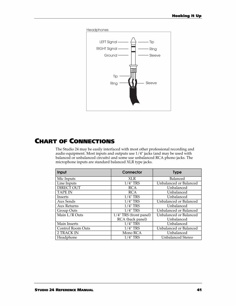
Hooking It Up
STUDIO 24 REFERENCE MANUAL 4 1
Headphones
Tip
Sleeve
LEFT Signal
Ground
Tip
Sleeve
Ring
Ring
RIGHT Signal
CHART OF CONNECTIONSThe Studio 24 may be easily interfaced with most other professional recording andaudio equipment. Most inputs and outputs use 1/4" jacks (and may be used withbalanced or unbalanced circuits) and some use unbalanced RCA phono jacks. Themicrophone inputs are standard balanced XLR type jacks.
Input Connector Type
Mic Inputs XLR BalancedLine Inputs 1/4" TRS Unbalanced or BalancedDIRECT OUT RCA UnbalancedTAPE IN RCA UnbalancedInserts 1/4" TRS UnbalancedAux Sends 1/4" TRS Unbalanced or BalancedAux Returns 1/4" TRS UnbalancedGroup Outs 1/4" TRS Unbalanced or BalancedMain L/R Outs 1/4" TRS (front panel)
RCA (back panel)Unbalanced or Balanced
UnbalancedMain Inserts 1/4" TRS UnbalancedControl Room Outs 1/4" TRS Unbalanced or Balanced2 TRACK IN Mono RCA UnbalancedHeadphone 1/4" TRS Unbalanced Stereo

Hooking It Up
4 2 STUDIO 24 REFERENCE MANUAL
CONNECTING TO AN UNBALANCED -10 DBV MULTITRACKRECORDER
Interfacing the Studio 24 with a typical multitrack recorder using semiprofessionalunbalanced phono or 1/4" phone jacks is a simple process. The Studio 24 is notdesigned to be used with the balanced inputs and outputs of the ELCO-typeconnector on the ADAT.
To interface with a typical unbalanced multitrack recorder:
1 Connect any microphones or instruments to be recorded into the MIC or LINEINPUTS of channels 1 through 8. Line-level instruments can also be connected tothe stereo channels.
2 Connect the DIRECT OUTs to the corresponding tape tracks by using either1/4"-to-RCA cables or RCA-to-RCA cables.
The Studio 24’s DIRECT OUT SOURCE switch allows you to re-route the Groupsto tape tracks without repatching. See the description on pages 54 and 55 fordetails.
3 Connect the tape machine’s outputs to the TAPE IN jacks of the same-numberedchannels of the Studio 24. Whenever you want to hear the playback of themachine, track 1 will appear as the MONITOR source of channel 1, track 2 willappear at channel 2, and so on. (For the mixdown, press the CHAN/MONREVERSE switch on each tape Channel to route the tape tracks to the ChannelFADERs).
Connecting your recorder(s) at the -10 dBV unbalanced level can yield good results,provided that the cables between the multitrack and the Studio 24 are no more than20 feet long.

Hooking It Up
STUDIO 24 REFERENCE MANUAL 4 3
CONNECTING TO A 2-TRACK MIXDOWN DECK
The mixdown deck is where everything comes together: the final mix. This is yourstereo master recording of the finished project (or a rough mix of a work in progress).A special pair of inputs of the Studio 24 are provided to hear the mixdown deck inthe Control Room mix only. If you connect the mixdown deck to regular line inputs,you run the risk of feedback by accidentally recording the output of the 2-track toitself.
To connect the mixdown deck to the Studio 24:
Unbalanced connection:1 Connect the Studio 24’s MAIN OUTS Left and Right to the inputs of the
Mixdown Deck using the appropriate cables (usually RCA phono on the Studio24’s back panel to RCA phono on the mixdown deck). You may also use abalanced 1/4” cables if you want to use the MAIN OUTS L and R jacks on theStudio 24’s top panel.Note that the nominal output of the top panel 1/4” MAIN OUTS in unbalancedoperation is -2 dBu, about 6 dB “hotter” than the nominal level of an unbalancedmixdown deck. Lower the input level controls of the mixdown deck to achieve the desiredsignal level, or lower the L/R master fader a little to compensate. The back panel RCAjacks are unbalanced -10 dBV nominal inputs and should work with many mixdowndecks.
2 Connect the Mixdown Deck’s outputs to the Studio 24’s 2 TRACK IN Left/RightInputs using 2-conductor cables (usually RCA phono-to-phono cables) oradapters.
3 The 2 TRACK IN jacks of the Studio 24 are RCA unbalanced, and will acceptonly -10 dBV unbalanced sources. Connect the RCA phono output of themixdown deck to these jacks. If the mixdown deck has balanced XLR outputs,you will need to make or purchase XLR-to-RCA cables or adapters.

Hooking It Up
4 4 STUDIO 24 REFERENCE MANUAL
CONNECTING TO A CONTROL ROOM AMPLIFIER
Connect the Studio 24’s CONTROL ROOM OUTS to the inputs of the amplifier usedfor the control room monitor speakers. The CONTROL ROOM LEVEL knob on theStudio 24 controls the level of the control room monitor speakers.
Note: These jacks are also TRS balanced. You may use unbalanced 2-conductor cablesif the power amp doesn’t have balanced inputs. If the amp features XLR inputs, use aTRS 3-conductor phone-to-XLR-male cable.
CONNECTING TO A HEADPHONE AMP
Monitor 1 and 2 may be used to set up a separate cue mix for musicians to overdubto while listening to headphones. Connect the MON 1 and 2 outputs on the backpanel to a suitable headphone amplifier, if you will use the monitor sectionseparately.
Tip: If you’d like your studio headphones to switch between MONITOR 1/2 and theControl Room mix, the HEADPHONE jack may be connected to an amplifier’sinputs using a tip-ring-sleeve stereo splitter cable (the same type used for Insertcables). This also may be used for a second set of Control Room or studioplayback monitors. Just keep the HEADPHONE LEVEL control at 2 o’clock orless.
CONNECTING TO A PATCHBAY
It may be easier in some installations to access everything by the use of a patchbay,which is several rows of jacks that are permanently connected to both the inputs andthe outputs of the Studio 24, the multitrack tape machine, and all of the outboardequipment. This is much more convenient, but a more expensive method thandescribed in the last section, and is not absolutely necessary for operation. In thiscase, the patching is the same as in the previous example except that it is now doneon the patchbay instead of at the top or back connectors of the console and multitracktape machine.
With a patchbay, it is also easier to make use of the AUX SENDS and RETURNS ofthe Studio 24. Different effects may be repatched to receive signal from whateverAux Send the session requires.
For information on connecting to effects, see the next chapter.

Effects and Signal Processing
STUDIO 24 REFERENCE MANUAL 4 5
CHAPTER 4:
EFFECTS AND SIGNALPROCESSING
CONNECTING AUX SENDS AND RETURNS TOOUTBOARD EFFECTS
Aux Sends 3 and 4 (labeled AUX 3/4 on the mixer) are derived post-fader, whichmeans that any changes in level in the fader will also change the Aux levels as well.The Auxiliaries are normally used as effects sends and are connected to whateveroutboard effects that are available (reverbs, chorus, multi-effects processors, delays)to be blended into the mix.
Both Auxes receive signal from the Channel fader only. If CHAN/MON REVERSE isin its up position, the Channel fader is controlling signal from MIC IN or LINE INand this will be the signal going to AUX 3/4 on that Channel. If CHAN/MONREVERSE is in its down position, the Channel fader is controlling signal from TAPEIN and this will be the signal going to AUX 3/4 on that Channel.
Note: If you want to use a separate effect on a single channel, use the INSERT jacks,not the Aux Sends (see next section).
To connect the Aux Sends and Stereo Aux Returns to outboard effects:
1 Connect the Aux Sends AUX 3 and AUX 4 to the input or inputs of youroutboard effects devices (like the Alesis Wedge or Midiverb 4). See the next pagefor more information about using stereo inputs (or not).
2 Connect the Outputs of these effects devices back into the Studio 24’s dedicatedinputs, called STEREO AUX RETURNS. There are four 1/4" STEREO AUXRETURN connectors (labeled in pairs as A and B on the top panel), enough fortwo stereo, four mono, or any combination of mono and stereo devices.
You can use any Aux Returns you wish, but most people connect the outputs of theunit being fed by Aux Send 3 into Stereo Aux Return A and plug the unit fed by AuxSend 4 into Stereo Aux Return B. Either or both Returns may be assigned to Groups1/2 for routing to the multitrack or to the L/R Main mix (which is the most commonassignment for effect returns).
You can also mix some of the Aux Return signal to the MON 1/2 mix by using thepurple MON 1/2 level knobs in the STEREO AUX RETURNS section.

Effects and Signal Processing
4 6 STUDIO 24 REFERENCE MANUAL
Left/RightOutputs
Left Input
Dry Defeat = ON
SHOULD YOU USE ONE OR TWO INPUTS TO EFFECTS?
If your effect unit has two inputs, in most cases you only need toconnect from ONE Aux Send to the LEFT (mono) INPUT of the effectunit, but you will still connect both the LEFT and RIGHT OUTPUTS ofthe effect to the Stereo Aux Return.
You may not need to connect anything to the right input of the effect, since manyeffect units use it only if the effect is connected directly between an instrument andan amplifier. In most mixing applications, you will set the effect’s wet/dry balanceall the way to wet. The effect device will generate an artificial stereo output from thesignal input. Check the manual for your effect device for more information.
On the other hand, true dual-channel effects processors (such as the Alesis Wedgeand Q20) should be connected to two different sends to take advantage of the dualprocessing capability.
Tip:Using MONITOR 1/2 as effects sends: Note that Mon 1 and 2 may be used asextra effect sends while mixing by connecting eight jumpers from the DIRECTOUT to the TAPE IN of each Channel.
Using the Stereo Channels as Effects ReturnsAlternatively, you may return effects to Channels 9 - 16. By connecting the stereoouts from the effect device to the L and R inputs of a stereo Channel, you now havethe ability to “mix” the effect’s level with the fader like you can with the signals on

Effects and Signal Processing
STUDIO 24 REFERENCE MANUAL 4 7
Channels 1 - 8.
Effects returned to a stereo Channel can be SOLOed, MUTEd, sent to the Groups androuted to L/R. Also, you have the ability to change the EQ of the effect’s signal, routeit to MON 1/2, and send it out AUX 3 or AUX 4.But be careful when you send an effect returned to a stereo Channel to an AUX. If the effectdevice’s signal source is AUX 3 for example, sending back out AUX 3 may cause feedback.
USING EFFECTSEffects such as reverb, chorus and delay are typically wired in a loop from anAuxiliary Send to a Stereo Aux Return (see the illustration on page 13). There are twobasic stages to getting a low-noise, distortion-free signal flow from an effect device:
SENDAdjust the send level from the Studio 24 to the effect device using the blueChannel AUX SENDs and the input controls of the effect device itself. This levelshould be as strong as possible without clipping the effect device, and withoutextreme settings on either the mixer or the effect.
RETURNAssign the Stereo Aux Return to the destinations you want:
• To hear effects in the control room and the headphone mix, or record themonto the mixdown deck, press the L/R assignment switch.
• To record effects onto the multitrack tape deck, press a GRP switch. AuxReturns A and B can send to GRP 1/2. And if the DIRECT OUT SOURCEswitch is set to GRP, it may be routed to any tracks.
Most complaints of “noisy effects” are due to send levels that are too low and returnlevels that are too high. You must structure the gain properly between the Studio 24and the effect device.
To set the level going to the effects device:
1 Set the Aux Send(s) in the Channel to about “2 o’clock. ”Set the Channel fader tothe nominal (“0”) position.
2 Start the signal source(s); i.e., play the tape or instrument at typical levels.To check the output level, select AUX 3/4 as the Control Room Source, and adjust theChannel send to a setting that gives an average meter reading of “0 dB” on the L/Rmeter.
3 Raise the input control of the effects device until its meter or clip LED showspeak level, then lower the input control a bit. Consult the manual for the effectdevice for more information.Some effect devices have level setting switches on the back; these should be set so that apeak level can be reached with reasonable settings (neither too high nor too low) of theinput control.
To set the level coming FROM the effects device:
In most cases, the output level of the effect device itself should be set relativelyhigh, at nominal or maximum. Lower the output of the device only if the meterkeeps the +10 LED on when the Stereo Aux Return is soloed, or if the effect levels are

Effects and Signal Processing
4 8 STUDIO 24 REFERENCE MANUAL
too loud even at low settings of the Stereo Aux Return LEVEL controls.
To hear effects in the control room monitors:
It’s possible to put effects into the Control Room or headphone mix withoutrecording them to the multitrack.
1 Press the L/R switch of the Stereo Aux Return.Make sure the GRP switches are in the up position. Otherwise, the signal will beassigned to the group and effects may be sent to the multitrack recorder.
2 Raise the Stereo Aux Return’s LEVEL control until you hear the desired volumeof effect return.
Remember that you can SOLO the Aux Return to make adjustments to the sound, ifdesired. You will be hearing the output of the effects device only, without any “dry”signal coming from the Channel.
To hear effects in the headphone/cue mix:
Often while recording, musicians would like to hear some reverb or delay in theirheadphone mix. It is possible to meet this need without actually recording the effect.If you’re using L/R as the “cue” feed, follow the steps for “control room monitors” above. Ifthe musicians’ headphone mix’s source is MON 1/2:
1 Select MON 1/2 as the Control Room source so you can hear what the studio ishearing.
2 Raise the MON 1/2 control (the purple knobs) of the Stereo Aux Return(s) untilthe desired balance is heard.
To record effects onto the multitrack:
In most cases, effects are added at mixdown instead of during tracking andoverdubbing. However, you can “record wet” (with effects) in order to use the samedevice for some other effect at mixdown, or because the effect is essential to the part.To do this, you simply:
1 Assign the Stereo Aux Return to the Group that you’re recording by pressing theGRP switch. Returns A and B can be sent to Groups 1 and 2.
2 Set the DIRECT OUT SOURCE switch(es) of the tracks you’re recording to the GRP (down) position.
3 To make sure you’re hearing what’s actually going to tape, make sure the L/Rswitch is up, and follow the procedure earlier in this section under “RecordingMultiple Sources” see pages 54 and 55.
If the effect is stereo, it must be recorded onto two tracks. The left Aux Return inputwill go to the Group 1 and the right Aux Return input will go to Group 2.
To record effects onto the mixdown deck:
This procedure is the same as for hearing effects in the control room monitorsdescribed earlier: assign the STEREO AUX RETURNS to L/R and adjust the LEVELcontrols.

Effects and Signal Processing
STUDIO 24 REFERENCE MANUAL 4 9
CONNECTING SIGNAL PROCESSORS TO INSERTJACKS
Inserts are used to connect signal processing devices directly into the signal path of aChannel, the Group outputs and the Main outputs. Normally, the device connectedwould be one that shapes the dynamics or tone of a signal (such as a compressor,gate, or EQ), rather than an effects device (such as a reverb). It is also possible toinsert a stereo signal processor into the signal path of the MAIN L/R OUTS, usingthe MAIN INSERT jacks. This is desirable when either a group of instruments, or theentire mix, needs to be processed.
All INSERT jacks on the Studio 24 are TRS jacks containing both an output (send)and an input (return). The tip of the plug is the Send and will be connected to theInput of the effects device or processor, and the ring of the plug is the Return and willbe connected to the Output of the effects device or processor.
A special Y-cable consisting of a TRS 1/4" plug on one end and two mono 1/4" plugson the other end is required. See the illustration below.
Tip = SEND
Sleeve = GROUND(Common)
Tip
Sleeve
Insert Jack
Ring = RETURN
Ring

Effects and Signal Processing
5 0 STUDIO 24 REFERENCE MANUAL

Recording
STUDIO 24 REFERENCE MANUAL 5 1
CHAPTER 5:
MULTITRACK RECORDINGAPPLICATIONS
RECORDING
SETTING LEVELS
To get the maximum performance from your mixer, you must set all audio levels toget the least amount of background noise (hiss or hum) while not distorting(overloading) the electronics. To do this, it’s important to set proper levels not onlywithin the Studio 24 itself, but throughout the rest of your audio system. Here aresome procedures to follow when you’re operating the Studio 24 to achieve a gainstructure (the signal level within each part of the system) that will give youprofessional results.
Maintain Proper TRIM and Input Levels
To set proper input levels on either a mic or line level signal:
1 With the mic or line level signal flowing through the Channel, depress theChannel’s SOLO button (the SOLO MASTER LED will light). The SOLO buttonshould be the only button pressed on the Channel at this point. If there are anyvolume controls on the instrument itself, they should be set to maximum.
2 Raise the Channel’s fader to the 0dB mark.
3 Observe the level on the MASTER LED Meter. Adjust the TRIM knob until thesignal hits +3 or +6 (the first two yellow LEDs). It’s OK if the top yellow (+10)lights during the loudest peaks, but if you ever see the CHANNEL PEAK LEDflash, you are within 3 dB of signal overload. Turn down the TRIM knob until thePEAK LED stops flashing.
Note: There is no TRIM control for the TAPE IN jack, because it is designed to handlethe full range of inputs generated by modern tape recorders.
Maintain Proper Fader LevelsIn typical operation, the Channel, Group and Master FADERS should be run at aboutthe “0 dB” or “nominal” position. NOTE: that’s about 2/3 of the way up the channelfader travel, but all the way up on the Group and L/R faders. This position gives thebest balance between maintaining adequate headroom and lowest noise. It alsoallows for any additional increase or decrease in level that might be required duringmixing. Ultimately, the channel fader levels are dependent on the requirements ofthe mix; the nominal level is only a starting point.If a large amount of EQ is used, it may become necessary to decrease either the TRIMcontrol, or the Channel FADER, or both. The EQ is capable of adding quite a bit ofgain and is a frequent cause of overload distortion problems.

Recording
5 2 STUDIO 24 REFERENCE MANUAL
The Studio 24 has been designed with plenty of headroom on the internal summingamplifiers (23 dB of headroom above a +4 dBu balanced output level). It is onlypossible to clip the mixer internally if several channels are at or near their maximumclipping point (with PEAK indicators flashing) and then sent at maximum gain to anoutput. You are in danger of this if:
• the meter is hitting the top of its range (“PK”) with the GROUP MASTERFADER set to nominal level, or
• the GROUP or MASTER FADER is set to -20 or lower, and the MASTER LEDMeter is reading 0 dB or above.
Once again, it may be necessary to decrease either the TRIM control, the ChannelFADERS, or both, of each of the Channels assigned to the Group.
Maintain Proper System LevelsAs a good rule of thumb, try to run most volume level controls of other equipmentreceiving signal from the Studio 24 (amplifiers, effect devices) at 3/4 or 75% of full, aswell. This will decrease the possibility of overload distortion and keep the amount ofbackground noise to a minimum.
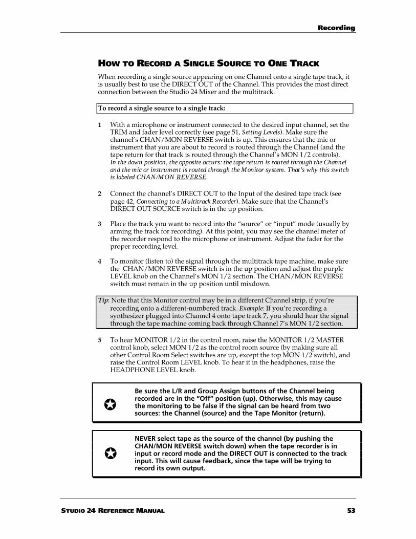
Recording
STUDIO 24 REFERENCE MANUAL 5 3
HOW TO RECORD A SINGLE SOURCE TO ONE TRACK
When recording a single source appearing on one Channel onto a single tape track, itis usually best to use the DIRECT OUT of the Channel. This provides the most directconnection between the Studio 24 Mixer and the multitrack.
To record a single source to a single track:
1 With a microphone or instrument connected to the desired input channel, set theTRIM and fader level correctly (see page 51, Setting Levels). Make sure thechannel’s CHAN/MON REVERSE switch is up. This ensures that the mic orinstrument that you are about to record is routed through the Channel (and thetape return for that track is routed through the Channel’s MON 1/2 controls).In the down position, the opposite occurs: the tape return is routed through the Channeland the mic or instrument is routed through the Monitor system. That’s why this switchis labeled CHAN/MON REVERSE.
2 Connect the channel’s DIRECT OUT to the Input of the desired tape track (seepage 42, Connecting to a Multitrack Recorder). Make sure that the Channel’sDIRECT OUT SOURCE switch is in the up position.
3 Place the track you want to record into the “source” or “input” mode (usually byarming the track for recording). At this point, you may see the channel meter ofthe recorder respond to the microphone or instrument. Adjust the fader for theproper recording level.
4 To monitor (listen to) the signal through the multitrack tape machine, make surethe CHAN/MON REVERSE switch is in the up position and adjust the purpleLEVEL knob on the Channel’s MON 1/2 section. The CHAN/MON REVERSEswitch must remain in the up position until mixdown.
Tip: Note that this Monitor control may be in a different Channel strip, if you’rerecording onto a different-numbered track. Example: If you’re recording asynthesizer plugged into Channel 4 onto tape track 7, you should hear the signalthrough the tape machine coming back through Channel 7’s MON 1/2 section.
5 To hear MONITOR 1/2 in the control room, raise the MONITOR 1/2 MASTERcontrol knob, select MON 1/2 as the control room source (by making sure allother Control Room Select switches are up, except the top MON 1/2 switch), andraise the Control Room LEVEL knob. To hear it in the headphones, raise theHEADPHONE LEVEL knob.
Be sure the L/R and Group Assign buttons of the Channel beingrecorded are in the “Off” position (up). Otherwise, this may causethe monitoring to be false if the signal can be heard from twosources: the Channel (source) and the Tape Monitor (return).
NEVER select tape as the source of the channel (by pushing theCHAN/MON REVERSE switch down) when the tape recorder is ininput or record mode and the DIRECT OUT is connected to the trackinput. This will cause feedback, since the tape will be trying torecord its own output.

Recording
5 4 STUDIO 24 REFERENCE MANUAL
RECORDING MULTIPLE SOURCES TO ONE TRACK
When more than one Channel is to be recorded onto the same track of a multitrackrecorder, it is necessary to assign all desired Channels to a Group, and connect theGroup Output to the input of the multitrack using the DIRECT OUT SOURCEfeature of the Studio 24.
If you connected the eight DIRECT OUT jacks to the track inputs of your recorder,you can assign several Channels, via the Groups, to any pair of DIRECT OUTs. Pressthe DIRECT OUT SOURCE switch to the GRP position on the Channel thatcorresponds to the track you want to record on. This routes all Channels assigned toa Group to the DIRECT OUT without repatching.
Example: if you want to record Channels 1, 2 and 3 onto track 6 on the multitrack, 1.assign these Channels to GRP, 2. pan all three Channels hard right and 3. press theDIRECT OUT SOURCE switch above Channels 5 and 6 to the GRP position. The GRP2 FADER now controls the overall level of the three Channels going to DIRECT OUT6.
To record two or more sources to a single track:
1 With microphones or instruments connected to the desired input channels, setthe input level correctly (see page 51, Setting Levels).
2 Assign each of the Channels you wish to record onto the same track to GROUPS1 and 2 by pressing the GRP button situated next to the Channel FADERs.If you want to record effects or other devices from a Stereo Aux Return, you may alsopress the GRP keys in the STEREO AUX RETURNS section.
3 Use the PAN control on each of the assigned Channels to position the signalseither fully to the left or fully to the right. If the panning is fully left, the Channelwill be routed to Group 1. If the panning is fully right, the Channel will be routedto Group 2.
4 The appropriate GROUP FADER will now control the level going to tape. Raisethe GROUP FADER to its maximum position. To check the level of the Group onthe Studio 24’s meter, press the GRP 1/2 switch in the CONTROL ROOMsection.
5 Be sure that the Group’s LINK TO L/R switch is in the “Off” position (up).Otherwise the signal will be assigned to the Main L/R Output directly, instead ofmonitoring what’s coming back from the multitrack via the MONITOR 1/2section.
6 To monitor the track through the multitrack tape machine, place the tapemachine track you are recording on into record or “input” mode, and raise theMON 1/2 control knob of the Channel the track’s output is connected to.
Be sure the L/R buttons are in the “Off” position (up) for theChannels being recorded. Otherwise, this may cause the monitoringto be false if the signals can be heard from two sources: theChannels and MONITOR 1/2.

Recording
STUDIO 24 REFERENCE MANUAL 5 5
Tip: Note that the overall level of Channels panned left is controlled by the GRP 1FADER; the overall level of Channels panned right is controlled by the GRP 2FADER. So if you’re not getting signal from one or more Channels, check theirPAN knobs. In this example, Channels 1, 2 and 3 must be panned hard right tobe correctly routed to DIRECT OUT 6. If they’re panned left, they will be routedto DIRECT OUT 5. Also, when you’re recording multiple sources to one trackusing this method, make sure that all channels are panned hard to the left orright as appropriate. This ensures that the PAN controls don’t reduce the outputlevel of the Channels by panning signal away from the GRP FADER.
RECORDING MULTIPLE SOURCES TO TWO TRACKS(STEREO)
Recording multiple sources onto two tape tracks is simple – you just use the Groups.Pan hard left all channels going to Group 1, and pan hard right all channels going toGroup 2. You can pan each channel to obtain the proper stereo positioning betweenleft and right.
To record multiple sources to two tracks in stereo:
1 With microphones or instruments connected to the desired input channels, setthe input level correctly (see page 51, Setting Levels).
2 Assign each of the Channels (or Aux Returns – remember that you can use thefour STEREO AUX RETURNS jacks as extra instrument inputs) you wish torecord onto the same track of tape to GROUPS 1 and 2 by pressing the GRPbutton situated next to the Channel FADER (or below the AUX RETURN LEVELknob).
3 Use the PAN control on each of the assigned Channels to position the signals asdesired between the left (Group 1) and right (Group 2).
4 The GROUP 1 and GROUP 2 FADERS will now control the levels going to tape.Raise them to the full up position (0).
5 Be sure that the Groups’ LINK TO L/R buttons are in the “Off” position (up).Otherwise the signals will be assigned to the Main Output directly, instead ofmonitoring what’s coming back from the multitrack on the Channel fader.
6 If you have the eight DIRECT OUTS connected to your multitrack, try thefollowing method:
Press the DIRECT OUT SOURCE switch down (to the GRP position) on theChannels that correspond to the track numbers you’re recording on. This routesthe GRP outputs to the DIRECT OUTS (as well as the GRP OUTS). Example: torecord Channels 1 - 4 onto tracks 7 and 8, press the DIRECT OUT SOURCEswitch at the top of Channels 7 and 8: this routes all Channels that have theirGRP switches down to DIRECT OUTS 7 and 8. This handy little feature allowsyou to record any Channel to any DIRECT OUT without repatching.
When using this method, note that the overall level of Channels panned left iscontrolled by the GRP 1 FADER; the overall level of Channels panned right iscontrolled by the GRP 2 FADER.
7 To monitor the tracks through the multitrack tape machine, place the tape

Recording
5 6 STUDIO 24 REFERENCE MANUAL
machine tracks you wish to record on into the record-ready or “input” mode,and raise the MON 1/2 LEVEL control knobs of the Channels the tracks’ outputsare connected to. Set the CONTROL ROOM SOURCE switch to MON 1/2 (allother CONTROL ROOM switches must be up). Set the Monitor PAN controls tohard left and right to hear the proper stereo image in the control room.
If you don’t perform this last step, the main PAN settings you make on thechannels you’re recording in step 3 will be incorrect in the final stereo image.
Be sure the L/R buttons are in the “Off” position (up) for theChannels being recorded. Otherwise, this may cause the monitoringto be false if the signals can be heard from two sources: theChannels and the Tape Monitors.

Recording
STUDIO 24 REFERENCE MANUAL 5 7
RECORDING TIPS
For the cleanest possible recording, the Group FADERS (or Channel FADERS if theDIRECT OUTS are being used) should be adjusted so that the level going to tapeaverages 0 VU on the meters of a typical analog multitrack tape machine, or peaksjust below MAX or 0 dBFS on a digital multitrack machine such as the Alesis ADAT.
ABOUT METERING
The meters of the Studio 24 are the instantaneous peak reading type, which arepreferred in digital recording where the “ideal” recording level comes close to, butnever exceeds the point where all the bits are filled (called 0 dBfs, for full scale). Notethat “0 dB” on the Studio 24’s meters means that the output of the Studio 24 is at“nominal” level (+4 dBu balanced, -2 dBu unbalanced or -10 dBV unbalanced,depending on the connector), as opposed to “0 dB” on a digital recorder like ADATwhich means “maximum” level (+5 dBV unbalanced). Peaks well above the “0 dB”level on the Studio 24’s meters should be common at normal operating levels foralmost all types of tape deck. Analog tape decks typically have between 10 and 13 dBof headroom above the nominal level, depending on the tape type and any noisereduction being used, and ADAT has 15 dB of headroom above nominal. Otherdigital decks have anywhere from 12 to 20 dB of headroom.
Meters of the tape deck will not necessarily match those of the Studio 24 on dynamicprogram material. With typical metering, analog VU meters may only read 0 dB,even though the Studio 24’s peak meters are reading levels between +5 and +10.However, a steady-state tone (such as that from the built-in oscillator) will read 0 dBon both the Studio 24 and most VU meters. Readings on combined peak/VU meters,such as those found on semiprofessional multitracks, will vary. Take the time to learnthe relationship between the Studio 24’s meters and your deck’s meters, using bothsteady-state tones and dynamic material.
If signal peaks cause the record meter to vary by more than 10 dB, a limiter orcompressor such as the Alesis 3630 Stereo Compressor may be patched into theINSERT jack of that channel to even out the peaks. In general, things will soundbetter if the meters remain at roughly the same level throughout the recording.
The two LED ladder meters of the Studio 24 will follow the Control Room sourceswitch and SOLO system. Changing the Control Room Level control will not affectthe meters.

Recording
5 8 STUDIO 24 REFERENCE MANUAL
OVERDUBBING
USING MONITOR 1/2 TO MONITOR THE MULTITRACK
Once you have recorded onto the multitrack tape machine, you’ll need to hear theplayback of those tracks, as you record new tracks in sync with the material alreadyon tape (see next section, Getting the Mix to Headphones). The signals coming backfrom the multitrack tape machine connect to the TAPE IN connectors of eachchannel, and during the overdubbing stage you’ll usually hear them via theMONITOR 1/2 system.
To listen to tape tracks via MONITOR 1/2:
1 Place the tracks of the tape machine you wish to monitor into the “Tape” or“Playback” position. Usually this is done simply by taking the tracks out ofRecord mode.
2 Make sure the CHAN/MON REVERSE button is up on each Channel that will beused to monitor the tape tracks. Raise the MON 1/2 LEVEL knobs on eachChannel being used for the tape tracks you want to hear.
3 Select MON 1/2 as the Control Room Source.
Tip: Alternatively, you may select L/R as the Control Room source, and press the“LINK TO L/R” switch under the MONITOR 1/2 MASTER. This will allow youto hear other sources from the Channel faders if they are assigned to L/R.
4 Play the tape and raise the MONITOR 1/2 MASTER until the peaks of the signalbriefly light the yellow LEDs in the meters.
5 Turn the CONTROL ROOM control knob up to the desired listening level.

Recording
STUDIO 24 REFERENCE MANUAL 5 9
USING THE CHANNEL FADERS TO MONITOR THE MULTITRACK
If you’re only recording a few inputs at a time, you may want to use a differenttechnique for monitoring. Instead of monitoring the multitrack through MON 1/2,you might prefer listening to recorded tracks through the Channels where you canuse the Channel faders to mix the tape tracks rather than the MON 1/2 knobs.
This is accomplished by pressing the CHAN/MON REVERSE switch on the desiredChannels down. By so doing, the TAPE IN jacks of the Channels becomes the faders’input source, and signals present in the MIC or LINE jacks are now routed to MON1/2. This switch simply “reverses” the input source of the Channel: either theMIC/LINE jacks or the TAPE IN.
Monitoring on the channel faders gives you a head start on your mixdown, and alsoallows you to start using the EQ, experiment with effects through AUX 3/4 or trydifferent PAN settings. Keep in mind, however, that you will not be able to recordany Mic or Line source that’s plugged into a channel simultaneously being used tomonitor a tape return. To hear any tracks you’re overdubbing/recording you willstill use the MONITOR 1/2 mix, on channels not being used for playback.
To listen to tape tracks on the Channel faders:
1 On the multitrack, set the tracks you want to monitor into playback mode(Record switched OFF).
2 On the Studio 24, make sure the GRP switches of the tracks you want to hear areall UP (off).
3 Press the CHAN/MON REVERSE switch at the top of the Channel (below TRIM)down for all tape tracks you want to hear. This makes the tape input jack thesource of the Channel FADER.
4 Assign the tape track Channels to L/R (the switch lowest on the channel strip).
5 Raise the Channel FADERS being used for the tape tracks you wish to listen to.
6 Raise the L/R MASTER FADER, make sure all CONTROL ROOM SOURCEswitches are UP (L/R) and adjust the CONTROL ROOM settings, as in theprevious section.
Do not arm any tracks being monitored this way. If the DIRECT OUTSOURCE switch is up, it can cause feedback!
7 If you’re doing an overdub, plug the source into the same channel you’rerecording onto. This channel’s CHAN/MON REVERSE switch must be UP. Putthat track into record-ready mode. Set the recording level on the channel faderas usual.
8 Turn down all MON 1/2 level controls except for the channel being recorded.Press the MON LINK TO L/R switch down. Adjust the MONITOR 1/2 controlfor the proper balance between the overdub and the previous tracks. Do notadjust the channel fader on this track--that will affect recording level.

Recording
6 0 STUDIO 24 REFERENCE MANUAL
Tape Returns

Recording
STUDIO 24 REFERENCE MANUAL 6 1
GETTING THE MIX TO THE HEADPHONES
Once you have the tape tracks returning to the mixer, it is simple to create a cue mixfor the musicians to listen to over headphones while overdubbing. The cue mix iscreated using MONITOR 1/2 on the Studio 24, because it is a pre-fader mix that isindependent from all other mixes. Follow the instructions in the previous pages toget a monitor mix if you have not already done so.
Built-in headphone ampThe simplest solution for headphone monitoring is to simply plug into theheadphone jack at the upper right hand side of the Studio 24. You may run a stereoextension cable from this jack; it will power most standard headphones. (If thephones aren’t loud enough, consider trying some more efficient headphones with alower impedance and a closed-cup design.)
The headphones will hear exactly what’s heard in the Control Room, as set by theCONTROL ROOM SOURCE buttons. With all buttons in the up position, theheadphones hear the L/R mix. Pressing any of the SOURCE buttons will send themix of the lowest button to the headphones (as well as to the Control Room).
Pressing SOLO will also affect the headphones. Only the CONTROL ROOM LEVELknob will not affect the headphones.
Note that if the LINK TO L/R switches on the GROUP and/or MONITOR 1/2MASTER sections are pressed, the signals coming from these busses will be added tothe L/R mix in the headphones.
Using an external headphone ampThe MONITOR OUTPUTS L and R on the Studio 24’s back panel may be connecteddirectly to the inputs of a headphone amplifier (see page 44, Connecting to aHeadphone Amp). In this case, the MONITOR 1/2 MASTER control will set the overalllevel going to the headphones.
Turn down the input controls (if provided) of the headphoneamplifier itself so that average levels from the monitor section (upto +10 on the meter) do not make the headphones too loud.
Option: You may use a standard “stereo splitter” cable with the TRS 3-conductor endplugged into the Headphone output jack and connect it to an amplifier, with theheadphone level set to about 12 o’clock.

Recording
6 2 STUDIO 24 REFERENCE MANUAL
MONITORING MIDI VIRTUAL TRACKS
If you are using a MIDI sequencer, the tracks being played “live” from synthesizers,sound modules and drum machines in synchronization with the tape are effectivelythe same as additional tracks on tape –– which is why they are called “virtual tracks.”
Stereo Channels 9 through 12 are particularly useful for virtual tracks. These fourChannels use inputs 9 through 16 that are arranged on the top panel as stereo pairs.Note that the Left jacks are mono inputs that can be panned from the Channel in thestereo mix like Channels 1 - 8 if the other jack of the pair is not plugged in. Extrasynthesizers and drum machines may be plugged into the LINE IN jacks of thechannels, and can be monitored on the Channel FADER or MONITOR 1/2, using theprocedures on pages 58 and 59. Since the point of virtual tracks is not to use up atrack of tape, just make sure that when the synthesizer is on the Channel FADER, itsGroup Assign switches are OFF so it doesn’t get recorded until the final 2-trackmixdown. Assign virtual tracks to L/R only.
But, if you really need to record the instruments on these Channels, assign them to aGroup and connect the GROUP OUTPUTS directly to the recorder’s track inputs.Alternately, you can assign Channels 9 through 12 to the DIRECT OUTs: press theDIRECT OUT SOURCE switch on the Channel that corresponds to the track numberyou want to record on and the Channel(s) assigned to GRP will be routed to theDIRECT OUT.
Tip: If you are using Monitors and Channels simultaneously for tape return andvirtual track monitoring, the L/R mix should be used for the performers’headphone mix, not MON 1/2.
1 Set the Control Room source to L/R (all CONTROL ROOM Select buttons up).
2 Press the LINK TO L/R switch in the MONITOR 1/2 MASTER section. Thismixes the MON 1/2 mix onto the L/R buss.
3 Use the MON 1/2 LEVEL knob on each Channel that has a virtual track to adjustyour mix of virtual instruments.
4 Press the CHAN/MON REVERSE buttons down on each Channel that has a tapetrack. Use the FADER on each of these Channels to adjust your mix.
5 Set the MONITOR 1/2 MASTER LEVEL control to its nominal position (about “2o’clock”). Adjust all other levels to taste. If you want to turn all the virtual tracksup or down in the mix simultaneously, use the MONITOR 1/2 MASTER LEVELcontrol.

Recording
STUDIO 24 REFERENCE MANUAL 6 3
BOUNCING TRACKS
Sometimes it is necessary to combine several tracks onto another track, particularlywhen you are running out of tape tracks. Example: Once you’ve recorded the vocalharmonies on four different tracks, you could bounce them all over to one track, ortwo tracks for a stereo mix, thereby freeing up the original four tracks.
When bouncing tracks, you must control the tape tracks being bounced with theChannel FADERS, instead of hearing them through MONITOR 1/2. You then routethe signals to a Group which corresponds to the track(s) you wish to bounce to.Example: If we were bouncing those four vocal tracks to track 5, we would press theCHAN/MON REVERSE button down for those channels, route them to Group 1(which is available to the input of track 5 on the tape deck via the DIRECT OUTSOURCE switch on Channel 5), create a desirable mix, and place track 5 in record.Here’s the recipe:
To bounce tracks to a single track (mono):
1 For each Channel (tape track) you wish to bounce, press the CHAN/MONREVERSE button so it is down.This selects the TAPE IN jacks as the source of the Channel FADERS.
2 Assign the Channels to Group 1 by pressing the GRP button next to theChannel’s fader.Make sure none of these channels is assigned to L/R. Also make sure that no unwantedchannels or Aux Returns are assigned to Group 1/2, and that none are being heardthrough the MONITOR 1/2 mix.
3 Turn each Channel’s PAN knob hard left.This routes the signals to Group 1 only.
4 Place track 5 into record-ready, and adjust the Group 1 MASTER FADER tomaximum.
5 Make sure that the DIRECT OUT SOURCE switch on Channels 5-6 is in its downposition.This sends the tracks being bounced via GRP 1 to DIRECT OUT 5 jack.
6 In the Control Room section, press the GRP 1/2 switch and make sure all otherswitches are off.This will allow you to hear Group 1 in the left Control Room monitor, and bring it up inthe Studio 24’s meter.
7 Adjust each Channel FADER to achieve a desirable mix.If necessary, you may need to adjust the Group Fader down to avoid clipping the tapetrack.
8 Rewind the tape, and record onto track 5 those portions you wish to bounce.
9 Tracks 1-4 are now available for recording new parts.
Tip: Monitoring through the recorder: Instead of monitoring the GRP 1/2 feed inthe control room, you may want to use MON 1/2, turning off all other monitorlevel controls except the track you’re bouncing to (track 5, in this example).This method ensures that the patching, track arming and levels are correct.

Recording
6 4 STUDIO 24 REFERENCE MANUAL
To bounce multiple tracks to two tracks (stereo):
1 For each Channel (tape track) you wish to bounce, press the CHAN/MONREVERSE button so it is down.This sends the tape tracks to the Channel FADERS.
Make sure that CHAN/MON REVERSE is UP on the Channels you’rebouncing to (Channels 5 and 6 in this example). Otherwise, feedbackmay occur.
2 Assign the Channels to Groups 1 and 2 by pressing the GRP buttons next to thechannel faders.
3 Raise the GRP 1 and 2 FADERS to the maximum position.
4 Place tracks 5 and 6 into record-ready, and select either GRP 1/2 or MON 1/2 asthe Control Room source. If you’re using MON 1/2, turn the monitor pan (theupper black knob, not the one close to the MUTE key) for track 5 hard left, andthe monitor pan for track 6 hard right.
5 Set the DIRECT OUT SOURCE switch of Channels 5 and 6 to its GRP (down)position.
6 Adjust each Channel’s PAN knob and FADER to achieve a desirable mix.
7 Rewind the tape, and record onto tracks 5 and 6 those portions you wish tobounce.
8 Tracks 1-4 are now available for recording new parts.

Recording
STUDIO 24 REFERENCE MANUAL 6 5
PLAYBACK/MIXDOWN
GETTING THE MIX TO THE 2-TRACK DECK
Once you have recorded your tracks and overdubs, you’re ready for the last stage ofmultitrack recording: the mixdown to stereo. This involves connecting the L/RMAIN OUT jacks to the left and right inputs of a cassette deck, DAT deck, CDrecorder or hard disc recorder. For more information on connecting the Studio 24 to atwo-track mixdown deck, see page 43.
Assign all Channels and STEREO AUX RETURNS being used to the L/R MASTERFADER, by making sure the L/R buttons for each is down. Then create a mix usingthe Faders for the selected channels.
Make sure the L/R switches of all unused Channels or AUX RETURNS are UP, to keep thenoise floor to a minimum.
Tip: If you want to record even more sources, the MONITOR LINK TO L/R may beused to bring line inputs 1 - 8 into the mix while the Channels mix down tracks 1- 8. See page 62.
MIXDOWN BASICS
Here is a simplified step-by-step way to establish a mix:
1 Press 2 TRACK as the source in the CONTROL ROOM section. This assures thatyou will hear only what is actually reaching the mixdown deck, and that it is inRECORD mode when you want it to be. You may test the 2-track to ControlRoom connection by playing back a pre-recorded tape or disc before inserting ablank one.
2 On the channels where you want to hear the tape track, press the CHAN/MONREVERSE switch down.Now the TAPE IN will appear at the channel input.
3 Make sure the channel L/R switches are down. Set the Main L/R fader at fulland raise the channel FADERS being used as tape returns to the desired levels.
4 Add the amount of effects desired by adjusting the AUX levels of each Channel.Be careful when setting these controls to avoid overloading outboard effects.
5 Assign the STEREO AUX RETURNS to L/R.
6 Raise the level of the STEREO AUX RETURNS. For quietest operation with thegreatest amount of headroom, it’s best to run the individual channel AUX Sendsat about the “2 o’clock” level. If the effects are too loud, turn down the AUXRETURNS, not the sends.
7 Adjust the input of the mixdown deck, or if necessary the Master L/R FADER, sothat the desired level is sent to the mixdown tape machine.

Recording
6 6 STUDIO 24 REFERENCE MANUAL
GUIDELINES FOR A ROUGH MIX
Creating a mix is easy; creating a great mix (one that jumps off the tape and hits youright in the face) is a lot harder. There are those engineers who are in demand just formixing because of their sense of balance between instruments causes the mix to comealive with excitement. Although outboard effects and tonal adjustments areimportant, you’d be surprised at how good a dry (meaning no EQ or effects) mix canbe if the balances between parts are right. When you add effects and EQ, it willsound that much better.
Since much of the art of mixing is totally subjective and up to the taste of theengineer, a basic balance between instruments is necessary first before any tonal oreffect enhancements can really become effective. Here’s a method to help you quicklycreate a “dependable” mix; one that sounds good no matter what speakers you mixor play back on. Although our example involves mixing the instruments found inpopular music, this method can be applied to any type of music regardless of theinstruments being used. Note: This is only a reference or starting point. Each song isunique and calls for different balances.
To create a dependable mix:
1 Begin with all the Channel ______ in the “-∞” (down) position.
2 Set the L/R MASTER _____ to the “0 dB” point (all the way up).
3 Raise the Kick Drum Channel _____ until the LED meters read “-3.”
4 Mute the Kick Drum Channel by switching the MUTE button to the “On” (down)position, so that the Kick can no longer be heard. DO NOT MOVE THE FADER!Just mute the Kick Channel.
5 Raise the Snare Drum Channel _____ until the LED meter reads “0.” Mute theSnare Drum Channel, the same as the Kick.
6 Raise the Hi-Hat Channel _____ until it reads “-12” on the LED meter. If anycymbals (ride or crashes) occur in the song, set those Channels to “-12.” Mute theHi-hat and Cymbals Channels.
7 Raise the Toms Channel faders. Set them so that the LED meter indicates “0.”Mute the Toms Channels.
8 Bring up the Bass Guitar Channel _____ so that the LED meter reads “-6.” Mutethe Bass Channel.
9 Raise the Channel faders with the rhythm guitar and/or keyboards so that theLED meters read “-12,” unless percussion instruments are involved (such ascowbell, triangle or shaker), in which case the meters should read “-18.” Mutethese Channels.
10 Raise the Channel faders with the keyboard pads, strings and/or organ so thatthe LED meters read “-24 .” Mute these Channels.
11 Raise the Channel faders with the melody and solo instruments (such as leadvocal, solo guitar, etc.) so that the LED meters read “-6.” Mute these Channels.
12 Raise the Channel faders with the background vocals and/or incidental

Recording
STUDIO 24 REFERENCE MANUAL 6 7
instruments so that the LED meters read “-12.”
13 Unmute all Channels and make balance adjustments as necessary.
The above process can be accomplished very quickly once you get the hang of it.Usually, it is done at least twice when “getting up” a mix. The first time is withouteffects or EQ to see what (if anything) the mix needs. The second time is after all theeffects and EQ have been added.

Recording
6 8 STUDIO 24 REFERENCE MANUAL

Sound Reinforcement
STUDIO 24 REFERENCE MANUAL 6 9
CHAPTER 6:
SOUND REINFORCEMENTAPPLICATIONS
Though the Studio 24 has been designed as a recording console, it makes an excellentconsole for live PA applications. It has just as much (if not more) headroom as a PAconsole, is more flexible, and has a much more powerful EQ than the typical stereoPA console.
CREATING A MONO HOUSE MIXMost sound reinforcement applications work best in mono, since so few members ofthe audience are seated in the ideal spot to hear the balance of a stereo sound systemeffectively. Also, a stereo sound system can be much more difficult to mix.
To configure the Studio 24 mixer in order to achieve a mono mix:
1 Pan all of the Channels fully left (or fully right).
2 Assign all Channels to L/R.A mono mix will now be present at the MAIN OUT L jack (or the MAIN OUT Rjack, if all Channels were panned to the right).
Note that the MONO switch above the GROUP faders may be used to assign theGroup signals to left and right equally, no matter what the pan position is. Follow theinstructions below for subgrouping, making sure that no channel is assigned to L/Rdirectly.
SUBGROUPING WITH THE GROUP FADERSThe Groups are extremely useful in sound reinforcement work. A Group can be usedto control the overall level of several Channels with the movement of only one fader.Here are two examples:
To control all the vocal mics from the Group 1 master fader:
1 Raise the selected Channel faders to the desired levels.
2 Unassign each of the selected Channels from the L/R Master Fader by switchingtheir respective L/R buttons to the “Off” (up) position.
3 Now assign each of the selected Channels to Group 1 by first switching the GRPbutton to its “On” (down) position. Then adjust the PAN control of each of theselected Channels so that it is fully Left.
4 Assign the Group to the Master faders by switching the LINK TO L/R switch toits “On” (down) position. The Group 1 _____ will now control the selectedChannels, and the combined signal will appear at the L/R MASTER FADERalong with the other Channels directly assigned to L/R.

Sound Reinforcement
7 0 STUDIO 24 REFERENCE MANUAL
To control a stereo submix of all the vocal mics from the Group 1 and 2 faders:
If you are doing a stereo mix, you may use two groups for a submix. Follow theinstructions above, but pan the microphones anywhere from left to right during step4. Make sure Group Faders 1 and 2 are both set to the same level to keep the properstereo balance.
STAGE MONITOR MIX
In typical stage/PA applications, the monitor section of a mixer is usually used toprovide stage monitor mixes while the Channel FADERs provide the house mix. Thisdepends on the Mic or Line inputs going to both the Channel faders as well as theMonitor section. Since the Studio 24 is fundamentally a recording mixer, it does notroute Channel inputs 1 - 8 (MIC or LINE) to MON 1/2 and the Channel faders at thesame time. (The stereo Channels are the exception because they are designed withMIC or LINE inputs routed to both MON 1/2 and the Channel FADERs.)
This can be corrected by simply making or purchasing 8 RCA-to-RCA “jumpers” thatconnect the DIRECT OUT to the TAPE IN of each Channel 1 - 8. Just make sure thatall CHAN/MON REVERSE and DIRECT OUT SOURCE switches are in their UPpositions.
When the jumpers are in place, all inputs to Channels 1 - 8 are routed to the DIRECTOUTs after the fader, then routed right back into the TAPE Ins which feed the MON1/2 mix. This way, the both the house mix and stage monitor speakers have the samemics and instruments available (unlike in the studio where the Channels have themics and instruments and the MON 1/2 mix handles tape returns).
Using the LEVEL and PAN knobs in the MON 1/2 section of each Channel, you cancreate two mixes for the stage monitors that is different from the house mix. Justkeep in mind that since the jumpers are creating a signal path from the Channelfaders, any fader changes you make to the house mix will affect the MON 1/2 stagemix.
Creating two separate stage monitor mixes is accomplished by using the MONITORPAN controls carefully. For example, the lead singer may wish to hear more drumsand vocals in his or her monitor being fed by the MON 1 output, while the leadguitarist wants more bass coming from the MON 2 output. Here’s the procedure:
To create two different stage monitor mixes:
Set the Control Room SOURCE switch to MON 1/2 (down). The MON 1/2 signalswill be present in the HEADPHONE jack. You can also connect your own monitorspeaker to the CONTROL ROOM OUTS to hear the stage monitor mixes.
1 On the Channel modules that you wish to be part of the stage monitor mix, turnup the MON 1/2 control until the desired balance is obtained.
2 To send a Channel only to MONITOR 1, adjust the PAN control (the upper blackknob above the purple LEVEL control) fully left (MON 1). To send a Channelonly to MONITOR 2, adjust the PAN control fully right (MON 2).
3 Use the MONITOR 1/2 MASTER to increase or decrease the overall volumegoing to the MONITOR OUTS jacks. The default (unity gain) position is markedwith a heavy dot at the “2 o’clock” position.

Sound Reinforcement
STUDIO 24 REFERENCE MANUAL 7 1
4 Route the MONITOR OUTS L and R jacks to the input of a stereo poweramplifier.Usually, a 1/3 octave graphic equalizer is patched into the line to notch out feedbackfrequencies. The Alesis M-EQ 230 is a perfect unit for this application.
5 Route the two speaker outputs of the amplifier to two different sets of stagemonitors.
Usually, some channels will have to be heard in both monitors. This requiresadjusting the monitor pan and level controls to taste.
ALTERNATE USES FOR THE MONITOR 1/2 SECTION:STEREO RECORDING DURING A LIVE CONCERT
The most popular and obvious application of the MONITOR 1/2 section to hear thetape tracks in the control room or headphones while using the main faders for thesources, during multitrack studio recording. But you should think of the MON 1/2section as an independent, 16x2 mixer (8 inputs for Channels 1 - 8 and 8 inputs forthe four stereo Channels) with an effects send, like this:
At a major concert, feeds from microphones are often “split” so they can be sent totwo different consoles: a monitor mixer on stage, and a house mixer in the audience(and, sometimes, a third console for multitrack recording). This allows engineers tochange the controls without affecting each other. Here are some examples of whyseparate mixes are needed:
• the recording truck needs to have microphones in the audience to record theapplause; but it would cause feedback if these microphones were sent to the PAsystem.
• the PA engineer needs to raise and lower levels during the show, with different
mixes for each song. But the multitrack recording engineer tries to set levels sothat each track is at the ideal maximum recording level for that track. (Therecording’s final mix levels will be set later, in a studio mixdown session.)
If you can afford several consoles and an expensive 2-way splitter box, good for you.But if you think of the monitor section of your Studio 24 as if it were a separate mixer

Sound Reinforcement
7 2 STUDIO 24 REFERENCE MANUAL
being fed by the same microphones, a whole set of possibilities open up.
USING MONITOR 1/2 TO FEED A CASSETTE DECK
Since the Studio 24 has a true stereo mixer independent of the main console, it can beused to create a stereo reference mix of a live concert, while the main faders set thePA mix. This technique is popular especially with artists who want to hear a tape toevaluate each performance. If you just record the mix going to the PA, the balancewill be wrong on the tape for instruments that don’t need to go to the PA (forexample, the lead guitarist’s kilowatt stack may be too loud to need PAreinforcement, but if you rely on bleed through the vocal mics for the recording, theguitar won’t sound right).
1 Connect the MONITOR OUTS L and R jacks to the input of your stereo tapedeck.
2 Make sure the MON 1/2 MASTER LINK TO L/R switch is OFF. Otherwise, themix you want for the recording will also go to the PA system.
3 Connect the 8 RCA-to-RCA jumpers between the DIRECT OUTs and the TAPEINs on the back panel.
4 Make sure that the CHAN/MON REVERSE and DIRECT OUT SOURCEswitches are in their up positions for Channels 1 - 8. This ensures that all mics andinstruments coming from the stage will be routed to both the Channel faders (the housemix) and the MON 1/2 (the record mix to cassette).
5 Set the monitor LEVEL and PAN controls for the recording mix you want.
This is what will happen with this setup:
• Certain changes you make on Channels 1 - 8 WILL affect the MON 1/2 mix:
moving the FADERmuting the Channelchanging EQ, including the 75Hz filterchanging the TRIM setting
• Other changes you make on the main channel will NOT be heard on therecording:
changing the PAN settingchanging the GRP or L/R assignmentschanging the GRP or L/R master levelsusing SOLO
• Any effect that goes to the STEREO AUX RETURNS (A and/or B) will berecorded on the cassette deck only if the purple MON 1/2 controls in this sectionare raised.
• If you have house mics for recording audience reaction or hall ambience, makesure to mute those Channels so they aren’t brought up in the PA system.

Sound Reinforcement
STUDIO 24 REFERENCE MANUAL 7 3
USING MONITOR 1/2 AS THE PA MIX DURINGMULTITRACK RECORDING
You may run into some situations where you need the opposite hookup from theabove, especially with acoustic jazz or folk recordings where a minimum of PA ormonitoring is needed, but the recording must be digitally pristine. For example,suppose you’re recording in a very small club, and only the vocalist needs any soundreinforcement because the instruments are loud enough acoustically or through theirown amplifiers.
1 Use MON 1/2 as the PA feed, with only 3 channels used (one for vocal, and twoeffect returns).
2 Use Group 1 as a mono drum mix, Group 3 as a mono keyboard mix, the L/Rmaster as a stereo guitar mix (there were acoustic and electric guitars, both instereo). Patch these four outputs (Groups 1/2 and L/R) to the first four tracks ofthe recorder.
3 Patch the vocal and bass from their respective TAPE OUTs without assigningthem to any of the main outputs:
Voila, an 6-track digital recording that is easy to manage, and a happy audience andvocalist.
The point of all these techniques is: don’t limit yourself in how you use the differentsections of the Studio 24. What works in one situation will require a differentsolution in another.

Sound Reinforcement
7 4 STUDIO 24 REFERENCE MANUAL
VIDEO PRODUCTION AND POST-PRODUCTIONThe Studio 24 lends itself extremely well to post-production applications where asoundtrack is being developed for video or film. In most situations, asynchronization system is being used, which ties together all of the time-basedequipment including one or more video tape recorders (VTRs), a multitrack taperecorder, and in many cases a computer running MIDI software. The softwareusually performs as a sequencer for adding virtual tracks (sequenced parts notrecorded to the multitrack tape), and recalling effects programs on MIDI-compatibleoutboard effects devices.
Video deck outputs may be patched to either the LINE IN or TAPE IN jacks in mostcases. To feed the output of the Studio 24 into a video deck, set the input of the videodeck to “line level” or “+4”, and connect either the GROUP or MAIN L/R OUTPUTSto the video deck using appropriate adapter cables (usually 1/4” TRS to XLR/Male).Make sure the input level of the video recorder is not set to “mic” or “-40” level.
In live production, a typical setup would be to plug microphones into the Studio 24,with direct outputs feeding an ADAT. Using the techniques listed above (“UsingMonitor 1/2 to feed a cassette deck”), make a reference stereo mix to record onto theVTR’s audio tracks (or onto a single audio track if one must be used to record timecode)

Description of Controls
STUDIO 24 REFERENCE MANUAL 7 5
CHAPTER 7:
DESCRIPTION OFCONTROLS
CHANNEL INPUT CONTROLS
TRIM
The TRIM knob adjusts the sensitivity of both the Mic and Line inputs. Proper settingof this control is essential for low-noise, distortion-free operation. In most cases,microphones require from 30 to 60 dB of preamplification, while line sources needmuch less or none at all. If the Channel PEAK LED flashes when the CHAN/MONREVERSE switch is up and signal is present, lower the TRIM control.
• Mic input gain: +10 dB (minimum) to +60 dB (maximum)
• Line input gain : -10 dB cut to +40 dB gain.
FADER/MONITOR SOURCE SWITCH:CHAN/MON REVERSE
This switch selects the source of the Channel (which includes the Channel Fader, EQ,INSERT jack and AUX 3/4) and the MON 1/2 system. In other words, where is thesignal coming from?
When this switch is UP:
• the LINE IN or MIC IN jack (having already passed through the TRIM control) is the source of the Channel, and...
• the TAPE IN jack is the source of MON 1/2.
When this switch is DOWN:
• the TAPE IN jack is the source of the Channel, and...
• the LINE IN or MIC IN jack is the source of MON 1/2. Example: If all the console’s CHAN/MON REVERSE switches are down, all the mainChannel faders will be getting signal from their respective Tape Returns. This wouldbe a typical mixdown patch. By releasing the CHAN/MON REVERSE switch, theChannel faders will get signal from the Mic/Line inputs, which is the typical patchfor recording & overdubbing.

Description of Controls
7 6 STUDIO 24 REFERENCE MANUAL
DIRECT OUT SOURCE SWITCH
On many mixing consoles, the concept of a Direct Out signal path is simple:whatever signal is input to a Channel is sent back to its own direct out jack. On theStudio 24, that’s exactly what happens when this switch is in its up position. If amicrophone or instrument is plugged into, say, Channel 5, that signal is present atDIRECT OUT 5 (post-fader, post-EQ). In fact, if the CHAN/MON REVERSE switchfor that Channel is in the down position, the TAPE IN signal will also be routedthrough the Channel then back to the same Channel’s DIRECT OUT.
Notice that each of these switches (there are four total on the Studio 24) controls twoChannels: in the up position, each pair of Channels has their post-fader mic or lineinputs (or TAPE IN if CHAN/MON REVERSE is pressed) routed to their respectiveDIRECT OUT.
In the down position, labeled GRP, the switch routes the output of the two Groups tothe DIRECT OUTs of the Channel pair. Example: if DIRECT OUT SOURCE is pressedon Channels 5 and 6, signal present on the GRP 1 fader, which is output to the GRP 1jack on the top panel, is also output to the DIRECT OUT 5 jack on the back panel. Bythe same token, signal present on the GRP 2 fader, which is output to the GRP 2 jackon the top panel, is also output to the DIRECT OUT 6 jack on the back panel.
Since both Groups are routed to two DIRECT OUTs, the PAN knobs come into play.Panning hard left routes the Channel’s signal to GRP 1 only and panning hard leftroutes the Channel’s signal to GRP 2. This means that any or all Channels assigned toa GRP can be re-routed to any of the eight DIRECT OUTs. This also means that twoor more Channels can be mixed in stereo and sent to any pair of DIRECT OUTs. Inany case, the GRP faders act as the master level faders for the signal going to theselected DIRECT OUT(s).
This feature adds enormous flexibility to the Studio 24’s Grouping function bycompletely eliminating the need to repatch every time you want to lay down a newtrack. Since the Groups are often used to feed the inputs of your multitrack forrecording, repatching can be frequent: having only two Groups being used to recordmultiple tracks (by overdubbing) means a lot of plugging and unplugging.
EQUALIZER SECTION
75 HZ SWITCH
The graphic over this switch shows what this does: it cuts frequencies below 75 Hz ata rate of 18 dB per octave. This is called a “high pass filter”, but some people preferto think of it as “low cut filter”. It is used to filter out undesirable subsonicfrequencies which may be present in the signal (air conditioning rumble, mic standnoise, etc.). If you push this switch, you often won’t hear any difference, because so fewinstruments (and no voices) actually have harmonics below 75 Hz, and manyloudspeakers don’t have good response below this point. As a rule of thumb, youdon’t want to press the 75 Hz switch on instruments such as kick drum, bass, orkeyboards; but it can be very useful on voices (especially if you’re boosting the 125Hz region to get an effect using the LOW or MID controls).

Description of Controls
STUDIO 24 REFERENCE MANUAL 7 7
HIGH AND LOW These are standard shelving “treble and bass” tone controls. The HIGH knob range is+/- 15 dB at a fixed frequency of 12 kHz. This means that frequencies above 12 kHzwill be boosted or cut by the same amount , and frequency response between 1 kHzand 12 kHz will gradually rise or fall to the shelving point. The LOW knob range is+/- 15 dB at a fixed frequency of 80 Hz. This means that frequencies below 80 Hz willbe boosted or cut by the same amount, and frequency response will gradually rise orfall from 80 Hz to about 1 kHz.

Description of Controls
7 8 STUDIO 24 REFERENCE MANUAL
MID EQ CONTROLS: LEVEL AND FREQ For Channels 1 - 8, the Studio 24 features a “semi-parametric midrange”, whichmeans that you can control some of the parameters or aspects of the midrange, besidesjust cutting and boosting a predetermined frequency range. Combined with theHIGH and LOW EQ controls, these make up a 3-band equalizer that can create thevast majority of tones you may need. The Mid controls consist of two knobs: FREQuency and MID gain control. Noticethat the FREQ control is a lighter shade of green, to help you identify it. The FREQ knob changes the center frequency of the EQ. The range is sweepablebetween 120 Hz (bass) to 13 kHz (extremely high treble). The MID knob controls how much boost or cut is applied to the band chosen. At thecenter detent position, there is no effect (flat response). Turning to the right amplifiesthe band, to a maximum of 15 dB. Turning to the left cuts the band, to a maximumcut of -15 dB. To learn how the midrange EQ works, put some broadband material (like a CD) intoa channel at a low level. Boost the mid level to its maximum, then sweep the FREQcontrol to hear the effect. You usually won’t use such a dramatic EQ setting on a mix,but it will help you get acquainted with the center frequencies this affects. Midrange: maximum/minimum gain, centered frequency Maximum/minimum frequency
The Stereo Channels have only a fixed midrange boost/cut knob. These Channelsaccept only line-level inputs, and a Frequency control is usually not necessary whenequalizing electronic instruments.
20.000
15.000
10.000
5.0000
-5.000
-10.00
-15.00
-20.0020 100 1k 10k 20k
00
AUDIO PRECISION AMPL(dBr) vs FREQ(Hz) 04 SEP 98 13:30:19
20.000
15.000
10.000
5.0000
-5.000
-10.00
-15.00
-20.0020 100 1k 10k 20k
00
AUDIO PRECISION AMPL(dBr) vs FREQ(Hz) 02 SEP 98 17:20:26
20.000
15.000
10.000
5.0000
-5.000
-10.00
-15.00
-20.0020 100 1k 10k 20k
00
AUDIO PRECISION AMPL(dBr) vs FREQ(Hz) 02 SEP 98 17:23:26

Description of Controls
STUDIO 24 REFERENCE MANUAL 7 9
AUXILIARY SEND SECTION
AUX 3 AND AUX 4 SENDS
These blue knobs are both mono post-fader sends typically used for effect sendswhose source is always the Channel FADER. The upper AUX 3 knob controls howmuch signal will be sent to AUX SEND 3. The AUX 4 knob controls how much signalwill be sent to AUX SEND 4. The unity-gain position of the AUX SENDS is the “2 o’clock position shown by theheavy dot. 10dB of gain is available at full rotation.
MONITOR 1/2 LEVEL AND PAN (CHANNELS 1 - 8) MONITOR 1/2 is a pre-fader, pre-mute stereo send typically used for control roommonitors and headphone feeds, or the stage monitors when the Studio 24 is used in alive PA application. Signal source: The MON 1/2 input comes from either the LINE IN/MIC IN jacks, orthe TAPE IN jack, as determined by the CHAN/MON REVERSE switch (see page75). Level: The purple LEVEL knobs control how much signal will be sent to theMONITOR 1/2 MASTER. The LEVEL knob’s unity-gain position is at full rotation. Pan: The left/right balance of the MON 1/2 mix is set by the black PAN controldirectly above this knob. By turning the PAN fully left, the signal is routed only toMON 1. When turned fully right, the signal is routed only to MON 2. Tip: Note that, in most cases, this Pan control affects what you hear in the Control
Room or headphones, but NOT what’s going to tape.
MONITOR 1/2 LEVEL AND BAL
(STEREO CHANNELS 9 - 16) As with Channels 1 - 8, MON 1/2 in the Stereo Channels are pre-fader, pre-mutestereo sends that are usually used for control room monitors/headphone feeds, orthe stage monitors. Since there are no tape returns to the stereo Channels, there is noCHAN/MON REVERSE switch, and inputs to these Channels are always routed pre-fader to the Monitor. Signal source: Stereo signals present in both inputs on the Channel are alwaysrouted to MON 1/2 (Left to MON 1 and Right to MON 2). An instrument pluggedinto the Left input only is routed as a mono signal to both MON 1 and MON 2. Aninstrument plugged into the Right input only will be routed to MON 2 only. Level: The purple LEVEL knobs control how much signal will be sent to theMONITOR 1/2 MASTER. Balance: Similar to the PAN control in Channels 1 - 8 that sets the left/right balance

Description of Controls
8 0 STUDIO 24 REFERENCE MANUAL
of a mono signal to the MON 1/2 MASTER, the BAL (balance) control sets theleft/right blend of a stereo signal (instruments plugged into both the L and R inputs)to the MON 1/2 MASTER. If you have an instrument plugged into the Left inputonly, it is routed as a mono signal, and the BAL knob sets the balance of this monosignal between the MON 1 and MON 2 outputs. Since instruments plugged into theRight jack are routed to MON 2 only, be careful when using the BAL knob: turning ithard left will cause the signal to disappear.
CHANNEL OUTPUT SECTION
CHANNEL PAN (CHANNELS 1 - 8) The Channel PAN control sends the output of the channel in continuously variabledegrees to either side of the stereo mix (if L/R switch is pressed – see the next page),or to odd-even sides of the GRP switch (pan left for Group 1, pan right for Group 2).The PAN control is a combination “where to/how much” control, in that it controlsboth the level and direction of a signal.
CHANNEL BALANCE (STEREO CHANNELS) Similar to the PAN controls on Channels 1 - 8, the BAL (balance) control allows youto adjust the stereo balance of the Left and Right inputs on the Channel. If a stereo instrument is connected to the Channel, the BAL knob acts much thebalance control on your home stereo system. As you rotate it left, it will lower thelevel of the signal in the right side of the stereo image; rotate to the right, and the leftside is diminished. You can connect two separate instruments to the L and R inputs of a stereo Channel.Use the BAL knob to adjust the relative levels of the two devices in the stereo image. If you have an instrument with a mono output, plug it into the L MONO jack. Itssignal will be present in both the left and right sides of the stereo mix and the BALcontrol will “pan” between them.
MUTE The MUTE switch turns off the signal from the Channel Fader. It disconnects thesignal from the L/R Main outputs, the Group outputs, the DIRECT OUT, and anyAux Sends. When pressed, the PEAK LED will light solid. Tip: The MUTE switch has no effect on the MONITOR 1/2 control.
PEAK LED The red Channel PEAK LED will flash when the channel’s signal level (measured atseveral places in the channel) is within 3 dB of “clipping” or distortion. If it flashes,reduce the TRIM knob (or the EQ, or the gain of any device at the INSERT jack) untilit stops flashing. The PEAK LED will come on solid when the MUTE key above it is pressed.

Description of Controls
STUDIO 24 REFERENCE MANUAL 8 1
-20 DB (SIGNAL PRESENT) LED The green “-20” LED will light whenever a signal of -20 dB or higher is presentanywhere in the channel circuit. This will help you determine what instruments areon what Channels, and if the TRIM controls are set properly. The “-20” LED has asecond function as an indicator for the SOLO switch, described in the next topic.
SOLO The SOLO button sends the Channel’s signal (and only that Channel’s signal, if noother SOLO buttons are pressed) directly to the Control Room section, cutting off anyother signals to the Control Room. It allows the engineer to focus on one signalwithout disturbing any other mixes. When SOLO is pressed, the green “-20” LED will light solid (even if no signal ispresent) and the master SOLO LED will light in the Master module section, to alertyou that Solo is active. You can adjust the output level of the signal(s) being soloed by turning the SOLOknob in the Master module section. If you’re listening to a soloed Channel in theControl Room, the CONTROL ROOM LEVEL knob will also affect the volume in theroom’s speakers. Likewise, if you’re listening to the solo in the headphones, theHEADPHONE LEVEL knob affects the solo volume. The meter will show the level of the soloed signal, unaffected by the master solo levelknob, so you can easily compare the level of individual channels and set the TRIMcontrol accurately.
GROUP ASSIGN SWITCH: GRP The GRP switch assigns the output of the Channel the two Group output busses,usually for recording on a multitrack. The amount of signal sent to GRP 1 or GRP 2 isdetermined by the Channel PAN knob. Panning hard left puts all of the Channel’ssignal to GRP 1; hard right puts all of the Channel’s signal to GRP 2. When theChannel’s PAN control is set to 12 o’clock, both Groups receive the same amount ofsignal and will be heard from the center of the stereo image.
Note that even when the Group switch is down, no signal will gofrom the Channel to an intended Group if the Channel PAN knob isturned to the wrong side. For example, if the GRP 2 fader is up butthe Channel is panned hard left, no signal will go to GRP 2.
Tip:Remember that the signals sent to GRP 1 and 2 with this switch can also appearat the Studio 24’s DIRECT OUT jacks, if the DIRECT OUT SOURCE switch (seep. 76) is in the down position.
L/R SWITCH
The L/R switch sends the channel’s signal to the Master L/R FADER, depending onthe setting of the Channel PAN knob. This switch is normally pressed for finalmixdown, or if the L/R mix is being used for monitoring in the Control Room andHeadphones.

Description of Controls
8 2 STUDIO 24 REFERENCE MANUAL
CHANNEL FADER
This linear 60 mm slide fader varies the level feeding the Channel PAN control andAssignment switches (L/R and GRP) and AUX 3/4.. The fader is set for unity gain(level in = level out) when it is set at the “0 dB” mark, 2/3 of the way up. When thefader is raised to its maximum, there is 10 dB of gain added to the signal.
STEREO AUX RETURN SECTION (A AND B) This section is essentially a four-input addition to the channels, squeezed into the topof the master section. This section is where you determine how much signal will beheard from effect devices.
MON 1/2 Turn these purple knobs in order to hear the Stereo Aux Returns in the Monitor 1/2mix. This is a pre-fader stereo send typically used for performer monitors andheadphone feeds. Signals from the left input will go to Monitor 1, and signals fromthe right input will go to Monitor 2. The MON 1/2 send is not affected by the LEVELcontrol beneath it.
LEVEL The gray LEVEL controls set how much signal from the Stereo Aux Return inputswill be sent to the Aux Return ASSIGN switches. In that sense, they are just like theChannel Faders in function.
L/R ASSIGN SWITCHES
These switches route the signals from the Stereo Aux Return jacks to the Master L/RFADER, with the left AUX input going to the left Master and right AUX going to theright Master. The Left input jack is mono, so if no plug is inserted into the Rightinput, the left signal will be connected to both sides, appearing in the center of thestereo image.
MASTER SECTION On the right hand side of the console are controls that affect the outputs of the mixer.
POWER AND PHANTOM INDICATORS
The switches for these indicators are located on the back panel. The PHANTOM LEDindicates that 48 volt phantom power is being applied to all 8 XLR jacks.
Phantom power should be turned off if there are no phantom-powered microphones connected, or if any MIC IN jack is connectedto any line-level source (such as the output of a VCR) or anyunbalanced source.

Description of Controls
STUDIO 24 REFERENCE MANUAL 8 3
HEADPHONE LEVEL
The LEVEL knob sets the overall level of the headphone output jack. TheHeadphones get the same signal appearing at the Control Room outputs (butindependent of the Control Room’s level control).
HEADPHONE JACK
The headphone jack on the top panel is designed for most stereo headphones. Theinternal headphone amplifier outputs the maximum power allowed by safetystandards. The impedance and efficiency of the headphones will determine themaximum volume available. Eight-ohm headphones may be louder at a given settingthan 150-ohm or 600-ohm headphones; however, there should be enough gain todrive any dynamic headphone to reasonable levels if the mixer is being run properly.
GRP ASSIGN SWITCHES
Press these switches if you want to record an effect (or other device plugged into theStereo Aux Return inputs) onto the multitrack. These switches route the signals fromthe Stereo Aux Return jacks to the GRP 1/2 FADERs, with the left AUX input goingto GRP 1 and right AUX going to GRP 2. The Left input jack is mono, so if no plug isinserted into the Right input, the left signal will be connected to both sides,appearing in the center of the stereo image.
SOLO IN PLACE SWITCH
The SOLO IN PLACE switches in the Stereo Aux Returns are a special kind of SOLOswitch to allow you to hear the effect returns in the Control Room mix. It sends thereturn’s post-fader signal (and only that Monitor’s signal, if no other SOLO buttonsare pressed) directly to the Control Room monitors, cutting off any other signals tothe Control Room.
MONITOR 1/2 MASTER This purple knob is the final overall level control for the Monitor 1/2 mix (the 12controls to its left, plus the two in the Stereo Aux Return section). This controls thelevel at the MONITOR OUTS 1 and 2 jacks on the back panel and the MON 1/2switch in the Control Room section. Adjust the Monitor 1/2 Master for the correctlevel feeding your external headphone or stage monitor amplifier. The nominal(unity gain) setting for this control is approximately “2 o’clock.” Set it there if theMON 1/2 mix will be used to add more inputs to the final mix using the LINKswitch, described below.
LINK TO L/R SWITCH
This is a powerful switch that allows you to turn the Studio 24 into a 28-input stereomixer, instead of a 16-input mixer with an in-line monitor section. The LINK TO L/Rswitch routes the MONITOR 1/2 MASTER signal to the Master L/R FADER. Regardless of whether the LINK switch is up or down, the MONITOR 1/2 signalalways feeds the control room and headphone source switch, as well as the

Description of Controls
8 4 STUDIO 24 REFERENCE MANUAL
MONITOR OUTS 1 and 2 jacks on the back panel. The LINK switch simply mixes orassigns the 12x2 monitor mix to the L/R mix buss as well. If you are sending the Monitor signal to the headphones or control room, but don’twant that signal on the Master L/R stereo output, leave the LINK TO L/R switch off(up). Tip: If monitors are not being used as extra inputs during mixdown, turn the LINK
switch off for the best signal-to-noise ratio.

Description of Controls
STUDIO 24 REFERENCE MANUAL 8 5
CONTROL ROOM/SOLO SECTION The Control Room section determines what you’ll hear in the control room and seeon the meters. The Control Room section does not affect any other mix of the Studio24–it just eavesdrops on them. The Solo controls are a special part of the ControlRoom mix, “taking it over” anytime any SOLO switch is pressed anywhere on theconsole, allowing you to hear only the soloed source instantly.
SOLO MASTER LEVEL
If any SOLO switch is pressed anywhere on the console, the MASTER SOLO LEDwill light indicating that the Control Room is receiving signal from the Solo bussinstead of the Control Room Source switch (see below). Note that if SOLO is engaged on a Channel that has no signal in it, you will hear nothing inthe Control Room until SOLO is turned off on that Channel. The SOLO knob sets the level you will hear in the Control Room when SOLO ispressed. Typically it is set a little above unity gain (about 2 o’clock), so that a singleinstrument will sound about as loud in the Control Room as the entire mix does,allowing you to focus. The type of Solo used in the Studio 24 is called “SIP” (Solo In Place). This permitsyou to hear instruments in their post-fader, post-pan arrangement. This isparticularly useful when mixing down, so you can adjust the levels of a stereo track,etc.
CONTROL ROOM LEVEL AND SOURCE
The CONTROL ROOM knob sets the overall Control Room level. Ideally, the controlroom amplifier’s input controls should be set so that full rotation of this control doesnot exceed the maximum level you want in the control room. The Control Room switches select the source of the Control Room mix (provided thatno SOLO source is turned on to override them). They also select the source of the twometers. When all switches are up, L/R will be selected, providing the Main L/R mix.
If any switches are pressed, you’ll hear the lowest switch (forexample, if “2 TRACK” is selected, you won’t be able to hear MON1/2 even if it is pressed).
Press MON 1/2 when you wish to route the musicians’ headphone mix to theControl Room. The output of AUX 3/4 or GRP 1/2 may also be selected. 2 TRACKcorresponds to the 2 TRACK INPUT jacks on the back panel of the Studio 24. Thesecan be used to listen to the output of a mixdown tape recorder, or CD player.

Description of Controls
8 6 STUDIO 24 REFERENCE MANUAL
METERS
The L and R meters will display whatever is selected as the Control Room source,including SOLO. When SOLO is on, the meters show you the post-fader level of anindividual Channel. These are peak-type meters which respond to the immediatelevel.
When the meters read “0” (top green LED), the signal is at itsnominal output (+4 dBu balanced, -2 dBu unbalanced) RMS.Typically, signals should be lighting a few yellow LEDs. Whenthe top red LED “PK” flashes, , signal is at +18 dB over nominal(that’s +22 dBu in a balanced circuit, +16 dBu in an unbalancedcircuit). But you still have 5 to 6 dB of headroom before thesumming amps distort (although, depending on your settings,you may be clipping some other part of the mixer in order toget level).
MASTER L/R FADER
The Master L/R fader adjusts the total output level of the stereo signal. It gets itssignal from the stereo busses, which are fed by any of the Channels, Monitors,Groups and Aux Returns which have their L/R or LINK switch down. They sendsignal to the MAIN OUT L and R jacks, and the CONTROL ROOM switch (where itcan be heard if all other switches are up). Unity gain is achieved when the fader is allthe way up.
GROUP MASTER CONTROLS The Groups may be used as sends to the tape recorder in recording applications, oras subgroups or zone masters in PA applications.
LINK TO L/R SWITCH
This switch is primarily used when submixing for PA applications, or possiblyduring a complicated recording mixdown. The LINK TO L/R switch functionsessentially the same as the LINK TO L/R switch under the MONITOR 1/2 MASTER:if the switch is up, anything routed to a group only goes to the group output and thefour DIRECT OUT SOURCE switches. When the switch is down, the group is sent tothe L/R mix as well. For example, if you have six different drum mics that are in perfect balance with eachother, but you need to bring the overall level of the drums down in the PA, turn the

Description of Controls
STUDIO 24 REFERENCE MANUAL 8 7
drum Channels’ L/R switches off, assign them to Group 1/2, and press Group 1/2’sTO L/R switch. The Group 1/2 faders are now a submaster for the entire drum mixin the left/right stereo mix feeding the PA or mixdown deck.
MONO SWITCH
Sometimes you may need two separate subgroups, instead of a stereo pair. TheMONO switch allows you to do this. When MONO is down, Group 1 will feed bothleft and right of the L/R mix, so, for example, it may be used as a vocal subgroup. (Ifthere was no MONO switch and you did a subgroup, all the vocalists would wind uphard-panned to the left side of the mix only.) Group 2 will also appear in the centerof the L/R mix.
GRP 1 AND 2 MASTER FADERS The two Group Master FADERS adjust the total output level of all signals assigned toeach Group. They get their signal from the GRP switches in the Channels and theStereo Aux Returns. They send signal to the two Group output jacks, the GRPControl Room switches, the LINK TO L/R switches explained above, and to theDIRECT OUT SOURCE switches in Channels 1 - 8. Tip: The GROUP FADER of the Studio 24, like the L/R Master, is at unity gain (“0
dB”) when all the way up, not at 2/3 travel as with some other consoles. Thisallows you a greater range of control on fadeouts, and makes it easier to “dial in”the best gain structure, since the “sweet spot” of the fader is in a useful part ofthe taper.
L/R MASTER FADER
This is a stereo 60 mm fader with its unity 0 dB position at the top of its travel, likethe group faders. Signal from the L/R output feeds the Control Room switch, and thetop and back panels’ MAIN OUT jacks which are normally connected to a mixdowndeck, or to a PA system.

Description of Controls
8 8 STUDIO 24 REFERENCE MANUAL
TOP PANEL INPUTS AND OUTPUTS
MAIN OUTS
Connect these jacks to your primary destination: the PA system’s inputs, or the 2-track mixdown recorder. Signal comes here from the L/R MASTER FADER, andpasses through the Main Inserts. This output is a true, 3-wire balanced differentialoutput with a maximum output level of +28 dBu.
The MAIN OUTS are also duplicated on the back panel but are unbalanced RCAjacks at a level of -10 dBV instead of balanced 1/4” connectors. They receive the samesignal as the top panel jacks, including any signal introduced by the MAIN INSERTS.
Both sets of jacks may be used simultaneously.
MAIN INSERTS
If you want to compress or equalize the stereo mix before it hits the L/R fader,connect your processing device to these jacks using a 1/4” TRS 3-conductor “splitter”cable (“tip” connector to the input of the device, and “ring” to the return), same asfor the channel insert jacks. See page 49.

Description of Controls
STUDIO 24 REFERENCE MANUAL 8 9
BACK PANEL
POWER SWITCH
This is the master power switch for the Studio 24. When it’s ON, the green LED onthe front panel will light.
POWER CABLE
An industry-standard removable power cable is shipped with your Studio 24. If youlose it, or need a longer or shorter length, compatible cables are available fromelectronics and computer stores. The type is sometimes referred to as a “NEMA toCEE” cable, or an “IEC power” cord.
Never defeat the grounding pin of the power cable. Use onlyapproved power cables.
PHANTOM SWITCH
When this switch is pressed, it applies phantom power to the XLR microphone jackson all Channels, and the yellow PHANTOM LED on the front panel will light. 48volts DC appears equally on pins 2 and 3 to be used by condenser-type microphonesrequiring external power. Since this voltage is equal, it is “invisible” to standardbalanced dynamic microphones, hence the name, “phantom power.” Check themanual for the mics you plan on using to make sure that this phantom method iscorrect before you apply power.
The PHANTOM switch must be turned off if any electronicallybalanced line source (such as the balanced output of a tape recorderor CD player) is connected to any XLR MIC IN jack; it could damagethe output circuitry of such units. When you turn PHANTOM off, it isnormal for it to decay gradually; make sure the yellow PHANTOMLED is totally off before plugging electronic units in to the MIC jacks.
Note: Make sure the channel volumes are set to minimum or are muted before switching the PHANTOM switch on. The voltage surge at initial turn-on may cause a loud “pop” in the system. Also, make sure that all mics are plugged in before phantom power is turned on.
CONTROL ROOM OUTS L AND R Connect these jacks to the input of your control room amplifier. Signal comes herefrom the Control Room section of the mixer. The jacks are 3-conductor with aforward-referenced ground to avoid ground loops, and may be used balanced orunbalanced.

Description of Controls
9 0 STUDIO 24 REFERENCE MANUAL
2 TRACK TAPE IN Connect the output of your 2-track (cassette, DAT, CD, reel-to-reel, etc.) to thesejacks. Any stereo source connected here may be heard in the control room mix only.The RCA jacks accept an unbalanced signal only; you may need to make or purchasecables that have RCAs on one end if your two-track has different output connectors.
MAIN OUTS
These unbalanced RCA jacks receive the same signal as the top panel MAIN OUTSbut output a -10dBV unbalanced signal. A common use for these outputs isconnecting the Studio 24 to a consumer cassette recorder or similar device. Also notethat the output from these jacks are affected by an effect device plugged into the toppanel MAIN INSERTS.
GROUP OUTPUTS You may connect these jacks to the first two inputs of a multitrack recorder such asthe Alesis ADAT, whose input normalling feature allows you to go to any of theeight tracks (Group 1 will feed tracks 1 and 5, etc.). In PA applications, you mayconnect these jacks to amplifiers for specific zones (Group 1 feeds a center cluster,Group 2 feeds side fills, etc.). In broadcast applications, these may be used to provide“mix minus” or matrix feeds. These jacks are true balanced +4 dBu nominal level(+28 dBu maximum) outputs on a TRS 3-conductor phone jack.
STEREO AUX RETURNS These four balanced TRS input jacks are located near the edge of the top panel foreasy repatching. Connect the output of your effects devices, or any other stereo inputthat doesn’t require EQ here. Traditionally, the “A” inputs are fed by an effect devicefed by AUX 3 and the “B” inputs by a device fed by AUX 4.
AUX SENDS The two output jacks, labeled AUX 3 POST and AUX 4 POST, are normallyconnected to the inputs of effect devices. The signal output from these jacks is post-fader, post-EQ. These jacks are 3-conductor TRS with a forward-referenced ground toavoid ground loops.
MON 1/2 The MON 1/2 jacks may be fed to a headphone amplifier in recording applications(to be used as the monitor system for the musicians), or to a stage monitor system inPA applications. Like the AUX SENDS, these jacks are 3-conductor TRS with aforward-referenced ground.

Description of Controls
STUDIO 24 REFERENCE MANUAL 9 1
CHANNEL INPUT/OUTPUT JACKS (8)
DIRECT OUT
This jack provides the output of the channel, post-fader. Connect it to the input of amultitrack tape recorder if you need to record more than two tracks at a time, or ifyou need only one microphone or line-level instrument per track. These are -10 dBVunbalanced outputs. In theory, the DIRECT OUT jacks provide a cleaner signal than that of the GROUP OUTjacks, but the difference is almost unmeasurable. You can be confident that if it’s moreconvenient for you, it’s perfectly OK to record from the Groups.
TAPE IN Connect the outputs of your multitrack tape recorder to these jacks. The output fromyour multitrack should be a -10 dBV (nominal) unbalanced line signal. Actually, anytypical line input (such as the output of a synthesizer or effect device) may beconnected to these inputs, so you could use the Studio 24 as a 24-input line mixer, byrunning the “tape inputs” through the MONITOR 1/2 section, linked to the L/RMaster. However, note that the TAPE IN jack does not pass through the TRIMcontrol, so extremely low-level or high-level signals should be connected to the LINEIN jack instead.
INSERT JACK
This is a 3-conductor unbalanced send/receive jack for signals going through theChannel. Note that INSERT will also affect the signal coming into the TAPE IN jack(when CHAN/MON REVERSE is in its down position). . The post-trim, pre-EQ, pre-fader signal appears at the tip connector, and the ring connector is an input to theEqualizer section of the channel. This is normally connected to an in-line effectprocessor such as a compressor or equalizer. See page 49 for more information onhow to use the insert jack.
LINE IN JACK (CHANNELS 1 - 8) This input jack may be used with balanced 1/4” TRS or unbalanced 1/4” sources.The signal from an instrument or other audio device (drum machine, MIDI soundmodule, etc.) will be routed through the Channel when the CHAN/MON REVERSEswitch is in its up position. Line signals pass through the TRIM control, which allows the LINE IN jack to accepta wide range of input levels (from +14 dBu nominal to -36 dBu nominal). When theTRIM is set to maximum, the LINE IN signal will be amplified 40 dB. When TRIM isat minimum, it will be attenuated (lowered) 10 dB.
The LINE IN and MIC IN jacks of a single channel may not be usedsimultaneously.

Description of Controls
9 2 STUDIO 24 REFERENCE MANUAL
LINE IN JACKS (STEREO CHANNELS) Similar to the LINE IN jacks on Channels 1 - 8, these input jacks may be used withbalanced 1/4” TRS or unbalanced 1/4” sources. Each of the stereo Channels 9 - 12 have two 1/4” TRS balanced LINE IN jacks perChannel, designed to accept line-level signals. Please note that signals present onthese four stereo channels are always routed to both the Channel FADER and MON1/2.
To use a mono source in a stereo channel, plug the single plug into the L/MONOjack. This allows you to use the BALance knob to “pan” the inputs between the L/Rand GRP 1/2 outputs.
If you plug a mono signal into the R (right) jack only, it will appear only on the right side ofthe mix, regardless of the setting of the BAL control. The BAL control will merely make itsofter or louder.
Signals then pass through the TRIM control, which is different from the TRIM onChannels 1 - 8. Notice that these Trim controls have a center position labeled LINE,which corresponds to a -10 dBV signal level. When the TRIM is set to hard right, theLINE IN signal will be amplified 15 dB. When TRIM is set to hard left, it will beattenuated (lowered) 15 dB.
MIC IN JACK (CHANNELS 1 - 8 ONLY) This balanced XLR connector is intended for use by low-impedance microphonesneeding preamplification. It is wired in the standard configuration (Pin 1 shield, Pin2 “hot”, Pin 3 “cold”) and will receive 48-volt phantom power when the PHANTOMswitch is on. As with the LINE IN jack, the signal from a microphone will be present in theChannel when the CHAN/MON REVERSE switch is in its up position, or will go toMON 1/2 if the switch is in the down position. When the TRIM is set to maximum, the MIC IN signal will be amplified 60 dB. WhenTRIM is at minimum, it will be amplified 10 dB. Warning for use with line sources: Though the MIC IN may be used with a balancedline-level source such as the output of a VCR, headroom will be limited; even withthe TRIM at minimum, it will clip at +11 dBu. For this reason, it’s better to connectbalanced line sources to the LINE IN jack using an XLR-to-1/4” TRS adapter or cable.
Never connect an electronic line input to the MIC IN jack if phantompower will be turned on. Doing this could damage the equipmentand the Studio 24.

Troubleshooting
STUDIO 24 REFERENCE MANUAL 9 3
CHAPTER 8:
TROUBLESHOOTING
TROUBLESHOOTING INDEX If you are experience problems while operating the Studio 24, please use thefollowing table to locate possible causes and solutions before contacting Alesiscustomer service for assistance.
Symptom
Cause
Solution
The POWER LED does notlight when the ON/OFFswitch is turned on.
No power. Check that the powercable is plugged inproperly.
Hiss/noise in output,faders must be raised totop to hear.
Input level is too low. Turn up the TRIMcontrols, lower the faders.Set the source(s) to ahigher level.
Effects are noisy. Effects send too low,return too high.
Turn output of effectdevice up and reduce AuxReturn level on mixer.Increase Aux Send levels.
Noise/hum. Ground loop betweendevices in system.
See page 35.
Unshielded cables. Don’t use speaker cablesfor mixer connections.
No signal from channel.
Device in INSERT jack isstopping the signal.
Remove insert jack, set itto bypass, or reverseinput/output of device.
PAN pot set in wrongdirection.
Set to left for MON 1 andGRP 1, to right for MON 2and GRP 2.
Microphone requiresphantom power.
Turn PHANTOM switchon.
Feedback when REC ispressed on recorder.
TAPE OUT is feeding itsown input.
Set CHAN/MONREVERSE to UP, or pressDIRECT OUT SOURCEdown and turn off GRPswitches on tape channels.Use MON 1/2 to heartape.
Crackling sounds. Dirty or corrodedconnections on back ofmixer.
Unplug and replugconnectors several times,clean plugs.
A microphone cable has asmall short or break.
Use SOLO to find thenoisy channel, and replacethe cable.

Troubleshooting
9 4 STUDIO 24 REFERENCE MANUAL
MAINTENANCE/SERVICE
CLEANING AND MAINTENANCE
Disconnect the AC cord, then use a damp cloth to clean the console’s metal andplastic surfaces. For heavy dirt, use a non-abrasive household cleaner such asFormula 409® or Fantastik®. DO NOT SPRAY THE CLEANER DIRECTLY ONTOTHE FRONT OF THE UNIT AS IT MAY DESTROY THE LUBRICANTS USED INTHE SWITCHES AND CONTROLS! Spray onto a cloth, then use the cloth to cleanthe unit. Here are some tips for preventive maintenance: • Periodically check the AC cord for signs of fraying or damage.
• Unplug the Studio 24’s power supply when not in use for extended periods oftime.
• Place a dust cover over the console when it is not in use.
• Vacuum around the faders to keep dust from falling into them. DO NOT SPRAYANY KIND OF “FADER CLEANER” or lubricant into the faders. Thesechemicals may work for a time but over the long run they attract more dirt andwill make it noisy again.
• The one place where contact cleaner is useful is on the back panel jacks andcables. Periodically disconnect the mixer from AC power and all cables, andclean the 1/4” and XLR cable ends with rubbing alcohol or electronic contactcleaner, then work the plug into the jack repeatedly. DO NOT SPRAYCONTACT CLEANER DIRECTLY INTO THE JACKS OF THE MIXER. It’s betterto use a damp plug to clean the jacks, or use a cotton or foam swab (but becareful not to get cotton or foam stuck in the mixer). While Alesis does notendorse the use of any specific product, certain contact enhancers (such asCramolin™) may be used to keep the connections from corroding in the future.
WARRANTY INFORMATION
This product is warranted by Alesis to the original purchaser against defects inmaterial and workmanship for a period of 1 year for parts and labor from the date ofpurchase. Complete terms of the Limited Warranty are stated on the Warranty Cardpacked with the product. Please retain a copy of your dated sales receipt for proof ofwarranty status should repairs be necessary.

Troubleshooting
STUDIO 24 REFERENCE MANUAL 9 5
REFER ALL SERVICING TO ALESIS
We believe that the Studio 24 is one of the most reliable mixing consoles that can bemade using current technology, and should provide years of trouble-free use.However, should problems occur, DO NOT attempt to service the unit yourself.Service on this product should be performed only by qualified technicians. THEREARE NO USER-SERVICEABLE PARTS INSIDE.
OBTAINING REPAIR SERVICE
Before contacting Alesis, check over all your connections, and make sure you’ve readthe manual. Your Alesis dealer may be able to offer further assistance.
Customers in the USA:If the problem persists, copy down the serial number of the Studio 24 and call AlesisUSA at 1-800-5-ALESIS and request the technical support department. Talk theproblem over with one of our technicians; if necessary, you will be given a returnauthorization (RA) number and instructions on how to return the unit to Alesis orthe nearest authorized service center. All units must be shipped prepaid and CODshipments will not be accepted.
You must indicate the RA number on the shipping label or the shipment will not beaccepted. If you do not have the original packing, ship the Studio 24 in a sturdycarton or road case, with shock-absorbing materials such as foam or “bubble-pack”surrounding the unit. Shipping damage caused by inadequate packing is not coveredby the Alesis warranty. Ship the unit with insurance via a carrier that provides atracking system.
Tape a note to the top of the unit describing the problem, include your name and aphone number where Alesis can contact you if necessary, as well as instructions onwhere you want the product returned. Alesis will pay for standard one-way shippingback to you on any repair covered under the terms of this warranty.
Field repairs are not authorized during the warranty period, and repair attempts byunqualified personnel may invalidate the warranty.
Customers outside the USA:Contact your local Alesis dealer for warranty assistance. Do not return products tothe factory unless you have been given specific instructions to do so. Your warrantyis valid only in the country of purchase.
Internet address: Important information and advice is available on our web site:
alesis.com
E-mail may be addressed to:

Troubleshooting
9 6 STUDIO 24 REFERENCE MANUAL

Specifications
STUDIO 24 REFERENCE MANUAL 9 7
SPECIFICATIONSAll measurements taken with an Audio Precision System One. All noise measurements takenwith trim at minimum and faders at unity gain with 22 Hz to 22 kHz bandwidth unlessotherwise specified. Main In & Out measurements made on balanced +4 dBu connectors. (+4dBu into a line input with faders at unity and the meter reading “0” will yield +4 dBu into abalanced load or -2 dBu into an unbalanced load. Unbalanced RCAs at -10dBV (.317 volts))Subject to change without notice.
FREQUENCY RESPONSE10 Hz – 75 kHz +0/-1 dB (any input to any output at nominal
operating levels)-3 dB Point: >125 kHz
CONNECTORSMIC IN jacks: Female XLR (Pin 1 ground, Pin 2 +,
Pin 3 -)LINE IN jacks Female 1/4" 3-conductor phone (Tip =
+, ring = -, sleeve = ground)TAPE IN, DIRECT OUT, 2 TRACK IN jacks: Female RCAINSERT jacks: Female 1/4" 3-conductor phone (Tip =
send, ring = return, sleeve = ground)Inserting plug to first "click" allows pre-fader direct output without breakingnormal signal flow
MAIN OUT (top panel),CONTROL ROOM OUT, andAUX SEND jacks: Female 1/4" 3-conductor phone
(Tip = +, ring = -, sleeve = ground)STEREO AUX RETURN jacks: Female 1/4" 2-conductor, unbalancedMAIN OUT (rear panel): Female RCA
LEVELSMIC IN -62 dBu to -12 dBu nominal, maximum
level +11 dBuLINE IN -42 dBu to +8 dBu nominal, maximum
level +31 dBu (balanced)TAPE IN -10 dBV nominal, +13 dBV (+15.2dBu)
maximumMAIN 1/4” OUTPUT LEVELS(when meter is at 0 VU) +4 dBu (1.24 volts) into a balanced load
-2 dBu into an unbalanced loadMAIN RCA OUTPUT LEVELS -10dBV (.316 volts)MAXIMUM OUTPUT LEVEL +21 dBu unbalanced, +27 dBu balanced
(5 dB above "PK" segment of mainmeter)
HEADROOM 23 dB above nominal output

Specifications
9 8 STUDIO 24 REFERENCE MANUAL
MAXIMUM GAIN +76 dB, MIC IN to L/R outputs,balanced+70 dB unbalanced+72 dB MIC IN to MON 1/2 OUT+82 dB MIC IN to AUX 3-4 OUT+85 dB, MIC IN to MONITOR OUT,balanced.
CHANNEL PEAK LED ON: 6 dB below channel clippingMETER: Peak type
-24 dB to PK (+18 dB over reference atL/R OUT, 5 dB before output clipping)
INSERT/DIRECT OUT (tip) Unity gainINSERT IN (ring) Maximum level +18 dBu
IMPEDANCEMIC IN 50-150 ohm nominal source impedance
(presents 3.8 k ohm load impedance)LINE IN 50 Ω to 2 k Ω nominal (>22 k Ω load
impedance)TAPE IN 50 Ω to 2 k Ω nominal (>16 k Ω load
impedance)OUTPUTS (MAIN, GROUP, DIRECT,AUX and MON): 150Ω unbalanced, 300Ω balanced
NOISE PERFORMANCE (TYPICAL)Dynamic Range 111 dB (Mic/Line to Main L/R output)Signal-to-noise ratio 88 dB (Mic/Line to Main L/R output)MIC IN to INSERT OUT -129 dB Equivalent Input Noise at
maximum gain, 150Ω sourceMic output noise (minimum gain, 150Ω source, to INSERT)
-91 dBuMix Output Noise (faders at nominal, trims minimum, 150Ω source terminations):
16 channels assigned -83 dBu unbalanced, -77 dBu balanced1 channel assigned -90 dBu unbalanced, -84 dBu balanced
DISTORTION (THD+N)Measured with a 0 dBu signal into a MIC IN jack; TRIM set for +15 dBu output at INSERTjack:At INSERT jack: Better than 0.0010%At MAIN OUT (+21 dBu): Better than 0.0015%
POWERUSA model: 120 VAC, 60 Hz 100 watts power
consumption maximum

Specifications
STUDIO 24 REFERENCE MANUAL 9 9
Top Panel:Mic Inputs XLR (8)Balanced Line Inputs 1/4" TRS (16)Channel Inserts 1/4" TRS (8)Aux Sends 1/4" TRS (2)Stereo Aux Returns 1/4" mono (4)Headphone Jack (1) 1/4" TRSMain and Group Inserts 1/4" TRS (4)Group Outs 1/4" TRS (2)L/R Main Outputs (balanced) 1/4" TRS (2)
Back Panel:Tape Inputs RCA/phono (8)Direct Outputs RCA/phono (8)Control Room and Monitor 1-2 Outputs 1/4" TRS (4)2-Track Inputs RCA/phono (2)L/R Main Outputs (unbalanced) RCA/phono (2)
Dimensions:Studio 24 Console (WxHxD) 15.38" x 16.65” x 4" (39 cm x
43 cm x 10 cm)—see dimensionaldrawing
Weight:Studio 24 Console 16 lbs. (7.3 kg)
Total Shipping Weight: Approximately 21 lbs. (9.5 kg)

Specifications
1 0 0 STUDIO 24 REFERENCE MANUAL
DIMENSIONAL DRAWINGS:

Specifications
STUDIO 24 REFERENCE MANUAL 1 0 1
GAIN DIAGRAM
+ 30
+ 20
+ 10
0
-10
-20
-30
-40
-50
-60
-70
-62 dBu MIC input
-12 dBu MIC input
-10 dBV TAPE input -2 dBu unbalanced
+ 8 dBu LINE input
Max. line input + 32 dBu
-42 dBu LINE input
Hi/mid/low+ /- 15 dB
Chan.fader
Masterfader
Phones/monitor
OUTPUTSBalanced + 4 dBu
Main Out, Tape OutUnbalanced-10 dBV
Aux3-4
Mon1/2
Max. balanced output+ 28 dBu
Max. internal level + 22 dBu
+ 10 db gain at max
dBu

Specifications
1 0 2 STUDIO 24 REFERENCE MANUAL
BLOCK DIAGRAM

Index
STUDIO 24 REFERENCE MANUAL 1 0 3
INDEX2 TRACK, 18, 40, 85
connecting, 43-20 dB (Signal Present) LED, 8175 Hz, 27, 76ADAT, 39
normalling w. Groups, 63assignment, 17, 27, 45Aux Return, 29
LEVEL, 82Aux Send/Return, 29Aux Sends, 24, 29, 45
as cue mix, 22connecting, 45
balanced, 37, 41Block Diagram, 102Bouncing Tracks, 63Connections, 41Control Room, 30, 85
connecting amp, 44level, 85Source, 22, 85
cue mix, 18, 61Direct Out, 20, 38, 53, 91effects, 24, 45, 47
in control room monitors, 48in MONITOR 1/2 mix, 48recording to multitrack, 48, 54returns. See Aux Returnstereo or mono input, 46
EQ, 26, 51Equalizer section, 76Fader, 82
cleaning/maintenance, 94Group Master, 87Master L/R, 86
FADER SOURCE, 59, 63FREQuency, 78gain, 82
of Mic and Line inputs, 75structure, 14, 51with effects, 47
Ground Loops, 35grounding, 6, 34Group Master
Faders, 87Group Outputs, 20, 27, 39, 54GRP 1/2
in Stereo Aux Returns, 24, 47headphone, 83Headphones, 30, 40, 61, 83
amplifier, 44headroom, 86high-pass filter, 27Impedance, 37, 98
Inputs, 41Aux Return, 45balanced, 43Mic, 36
Insert, 38, 45, 49Main L/R, 39, 40, 88
L/Rchannel, 81Stereo Aux Return, 24
L/R Master Fader, 87LED
Peak, 80Solo, 81
LevelAux Return, 82setting, 26, 51
Levels, 97LINE IN, 26, 36LINK TO L/R, 28, 58, 62, 83Main
Inserts, 39, 40MAIN OUTS, 39Master
L/R FADER, 86MASTER SECTION, 82maximum level, 97Meters, 31, 57, 86MIC IN, 26, 36, 92MIDI
virtual tracks, 62mix minus, 90mixdown, 18Mixing, 17
example, 66Group Faders as Subgroups, 69PA, 69stage monitor, 70
MON 1/2in Stereo Aux Returns, 29, 82
monitor, 28on channel faders, 59TAPE IN, 58
MONITOR 1/2, 22, 28, 79Master, 83
monitor speakers, 30MONO
Group, 87output for PA systems, 69
multitrack, 17, 20, 25, 42MUTE, 80noise, 35, 52noise, 98Outputs, 41
Aux Sends, 40

Index
1 0 4 STUDIO 24 REFERENCE MANUAL
Group, 87overdubbing, 18, 58, 61Overload, 80PA systems, 69Pan
Channel, 80Monitor, 22, 79
parametric EQ, 26Patchbay, 44PEAK, 13
as MUTE indicator, 80Channel, 80
PHANTOM, 82, 92PK, 13
in L/R meter, 86post-fader, 45Power, 34Power cable, 6, 89recording, 17, 51, 53Returns
see STEREO AUX RETURNS, 82send/receive, 24Setting Levels, 51signal flow, 25, 102SOLO, 30, 31, 81
in Stereo Aux Return, 83
level, 85SOLO IN PLACE, 31, 83sound reinforcement, 69source, 17stage monitoring, 70STEREO AUX RETURNS, 24, 29, 40, 45, 82Subgrouping, 27, 69TAPE IN, 22, 26, 28, 37, 42, 91TO L/R switches, 54, 69tracking, 18TRIM, 26, 75
adjusting using SOLO, 51range, 91, 92
TRS (tip-ring-sleeve) plug, 37on Insert cable, 49
unbalancedline input, 37tape in, 42
unity gainin Channel Faders, 82in Group Faders, 87in L/R master fader, 86in MON 1/2 master level, 70
video, 74XLR, 36