Embed Size (px)
Citation preview

Cat.No.R90E-13
POSISTORr for Circuit Protection
R90E.pdfSep.24,2012
!Note • Please read rating and !CAUTION (for storage, operating, rating, soldering, mounting and handling) in this catalog to prevent smoking and/or burning, etc.• This catalog has only typical specifi cations. Therefore, please approve our product specifi cations or transact the approval sheet for product specifi cations before ordering.

EU RoHS Compliant All the products in this catalog comply with EU RoHS. EU RoHS is "the European Directive 2011/65/EU on the Restriction of the Use
of Certain Hazardous Substances in Electrical and Electronic Equipment." For more details, please refer to our website 'Murata's Approach for EU RoHS'
(http://www.murata.com/info/rohs.html).
R90E.pdfSep.24,2012
!Note • Please read rating and !CAUTION (for storage, operating, rating, soldering, mounting and handling) in this catalog to prevent smoking and/or burning, etc.• This catalog has only typical specifi cations. Therefore, please approve our product specifi cations or transact the approval sheet for product specifi cations before ordering.
CONTENTS POSISTORr and "POSISTOR" in this catalog arethe trademarks of Murata Manufacturing Co., Ltd.
Part Numbering 2
Basic Characteristics of POSISTORr 5
Selection Guide 7
Application Matrix 8
Application Notes 9
Overcurrent Protection Chip Type 13
Chip Type Specifications and Test Methods 20
Overcurrent Protection Narrow Current Band 30V Series 22
Overcurrent Protection Narrow Current Band 51/60V Series 25
Overcurrent Protection Narrow Current Band 140V Series 30
Overcurrent Protection 16V Series 33
Overcurrent Protection 24/30/32V Series 36
Overcurrent Protection 56/80V Series 43
Overcurrent Protection 125/140V Series 49
Overcurrent Protection 250/265V Series 56
PTGL Series Narrow Current Band Specifications and Test Methods 64
PTGL Series Specifications and Test Methods 66
Inrush Current Suppression (Less than 100μF) 67
Inrush Current Suppression for High Capacitance (100μF or more) 68
Inrush Current Suppression Specifications and Test Methods 69
Overheat Sensing Chip Tight Tolerance Type 70
Overheat Sensing Chip Type 71
Overheat Sensing Chip Type (Related Data) 72
Overheat Sensing Chip Tight Tolerance Type (Reference Data) 73
Overheat Sensing Chip Type (Reference Data) 76
Overheat Sensing Chip Tight Tolerance Type Specifications and Test Methods 78
Overheat Sensing Chip Type Specifications and Test Methods 81
Overheat Sensing Lead Type 82
Temperature Sensor Lead Type Specifications and Test Methods 86
!Caution/Notice 87
Chip Type PRG/PRF Series Package 97
Lead Type PTGL/PTF Series Package 98
1
2
3
4
5
6
7
8
9
10
11
12
13
14
1
2
3
4
5
6
7
8
9
10
11
12
13
14
R90E.pdfSep.24,2012
!Note • Please read rating and !CAUTION (for storage, operating, rating, soldering, mounting and handling) in this catalog to prevent smoking and/or burning, etc.• This catalog has only typical specifi cations. Therefore, please approve our product specifi cations or transact the approval sheet for product specifi cations before ordering.
2
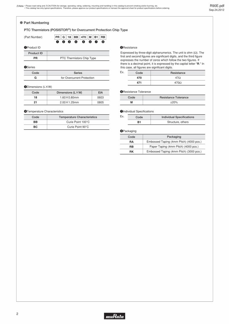
o Part Numbering
y
M
e
18
w
G
r
BB
t
470
u
B1
i
RBPR
q
qProduct ID
wSeries
rTemperature Characteristics
yResistance Tolerance
uIndividual Specifications
PTC Thermistors (POSISTORr) for Overcurrent Protection Chip Type
PR PTC Thermistors Chip Type
M
G for Overcurrent Protection
BB
BC
Curie Point 100°C
Curie Point 90°C
±20%
Temperature Characteristics
B1
Individual Specifications
Product ID
Code
Code
Code
Series
Resistance Tolerance
Code
(Part Number)
tResistance
Expressed by three-digit alphanumerics. The unit is ohm (Ω). The first and second figures are significant digits, and the third figure expresses the number of zeros which follow the two figures. If there is a decimal point, it is expressed by the capital letter "R." In this case, all figures are significant digits.
470
471
Ex.
Ex.
47Ω
470Ω
Code Resistance
Structure, others
eDimensions (LgW)
18
21
1.60g0.80mm
2.00g1.25mm
Code Dimensions (LgW)
0603
0805
EIA
iPackaging
RA
RB
RK
PackagingCode
Embossed Taping (4mm Pitch) (4000 pcs.)
Paper Taping (4mm Pitch) (4000 pcs.)
Embossed Taping (4mm Pitch) (3000 pcs.)

R90E.pdfSep.24,2012
!Note • Please read rating and !CAUTION (for storage, operating, rating, soldering, mounting and handling) in this catalog to prevent smoking and/or burning, etc.• This catalog has only typical specifi cations. Therefore, please approve our product specifi cations or transact the approval sheet for product specifi cations before ordering.
3
y
Q
e
18
w
F
r
BB
t
471
u
B5
i
RBPR
q
qProduct ID
wSeries
rTemperature Characteristics
yResistance Tolerance
uIndividual Specifications
PTC Thermistors (POSISTORr) for Overheat Sensing Chip Type
PR PTC Thermistors Chip Type
Q
R
F for Overheat Sensing
AR
AS
BA
BB
BC
BD
BE
BF
BG
Curie Point 120°C
Curie Point 130°C
Curie Point 110°C
Curie Point 100°C
Curie Point 90°C
Curie Point 80°C
Curie Point 70°C
Curie Point 60°C
Curie Point 50°C
Special Tolerance
Special Tolerance
Temperature Characteristics
B5
Individual Specifications
Product ID
Code
Code
Code
Series
Resistance Tolerance
±5°C
±3°C
Sensing Temp. Tolerance
Code
(Part Number)
tResistance
Expressed by three figures. The unit is ohm (Ω). The first and second figures are significant digits, and the third figure expresses the number of zeros which follow the two figures.
471
Ex.
Ex.
470Ω
Code Resistance
Structure, others
eDimensions (LgW)
15
18
21
1.00g0.50mm
1.60g0.80mm
2.00g1.25mm
Code Dimensions (LgW)
0402
0603
0805
EIA
iPackaging
RA
RB
RC
PackagingCode
Embossed Taping (4mm Pitch) (4000 pcs.)
Paper Taping (4mm Pitch) (4000 pcs.)
Paper Taping (2mm Pitch) (10000 pcs.)

R90E.pdfSep.24,2012
!Note • Please read rating and !CAUTION (for storage, operating, rating, soldering, mounting and handling) in this catalog to prevent smoking and/or burning, etc.• This catalog has only typical specifi cations. Therefore, please approve our product specifi cations or transact the approval sheet for product specifi cations before ordering.
4
qProduct ID
eDimensions
yResistance Tolerance
uIndividual Specifications
PTC Thermistors (POSISTORr)
for Overcurrent Protection / for Inrush Current Suppression / for Overheat Sensing Lead Type
PT PTC Thermistors
H
K
M
N
Q
±25%
±10%
±20%
±30%
Special Tolerance
3P51
Individual Specifications
Product ID
Code Resistance Tolerance
Code
(Part Number)
tResistance
Expressed by three-digit alphanumerics. The unit is ohm (Ω). The first and second figures are significant digits, and the third figure expresses the number of zeros which follow the two figures. If there is a decimal point, it is expressed by the capital letter "R." In this case, all figures are significant digits.
R22
2R2
220
Ex.
Ex.
0.22Ω
2.2Ω
22Ω
Code Resistance
Lead Type, others
iPackaging
A*
B*
PackagingCode
Ammo Pack
Bulk
wSeries
FL
FM
GL
for Overheat Sensing Lead Type
for Overheat Sensing with Lug-terminal
for Current Control (Over Current Protection · Inrush Current Suppression) Lead Type
Code Series
rTemperature Characteristics
04
05
07
09
10
12
13
14
16
18
20
AR
AS
BA
BB
BC
BD
BE
BF
BG
BH
Curie Point 120°C
Curie Point 130°C
Curie Point 110°C
Curie Point 100°C
Curie Point 90°C
Curie Point 80°C
Curie Point 70°C
Curie Point 60°C
Curie Point 50°C
Curie Point 40°C
Temperature Characteristics
Code
Code
Dimensions
Nominal Body Diameter 4mm Series
Nominal Body Diameter 5mm Series
Nominal Body Diameter 7mm Series
Nominal Body Diameter 9mm Series
Nominal Body Diameter 10mm Series
Nominal Body Diameter 12mm Series
Nominal Body Diameter 13mm Series
Nominal Body Diameter 14mm Series
Nominal Body Diameter 16mm Series
Nominal Body Diameter 18mm Series
Nominal Body Diameter 20mm Series
u
3P51
r
AR
w
GL
t
220
y
M
i
A0PT
q e
07
R90E.pdfSep.24,2012
!Note • Please read rating and !CAUTION (for storage, operating, rating, soldering, mounting and handling) in this catalog to prevent smoking and/or burning, etc.• This catalog has only typical specifi cations. Therefore, please approve our product specifi cations or transact the approval sheet for product specifi cations before ordering.
5
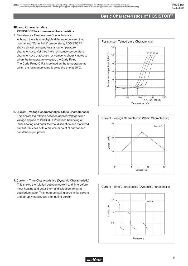
1. Resistance - Temperature CharacteristicsPOSISTORr has three main characteristics.
Although there is a negligible difference between the normal and "Curie Point" temperature, POSISTORr shows almost constant resistance-temperature characteristics. Yet they have resistance-temperature characteristics that cause resistance to sharply increase when the temperature exceeds the Curie Point.The Curie Point (C.P.) is defined as the temperature at which the resistance value is twice the one at 25°C.
2. Current - Voltage Characteristics (Static Characteristic)This shows the relation between applied voltage when voltage applied to POSISTORr causes balancing of inner heating and outer thermal dissipation and stabilized current. This has both a maximum point of current and constant output power.
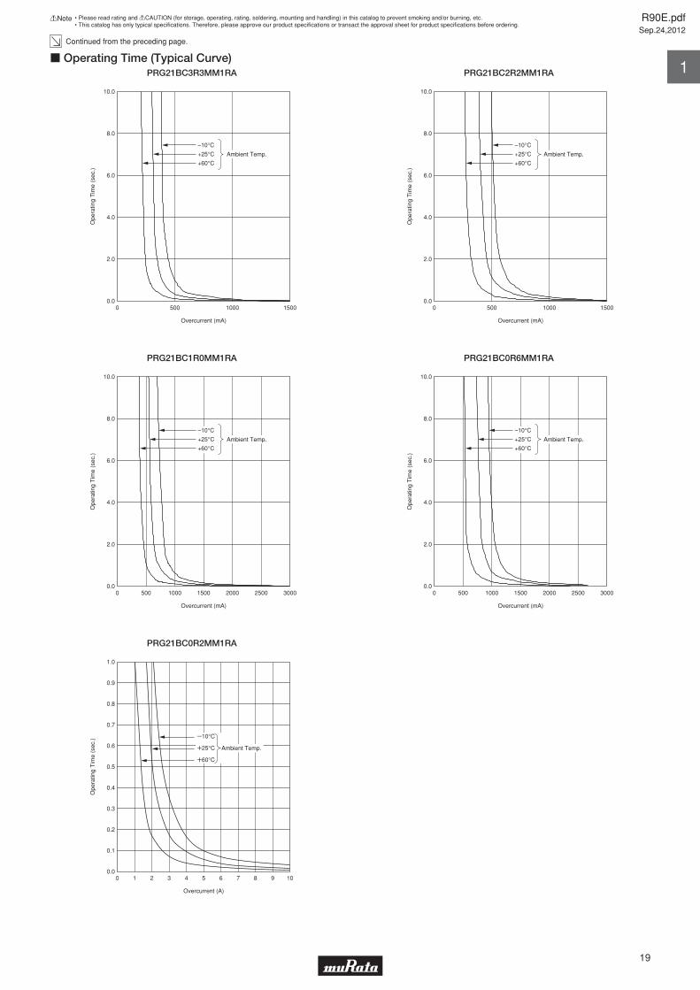
3. Current - Time Characteristics (Dynamic Characteristic)This shows the relation between current and time before inner heating and outer thermal dissipation arrive at equilibrium state. This features having large initial current and abruptly continuous attenuating portion.
Resistance - Temperature Characteristic
cBasic Characteristics
Res
ista
nce
Cha
nge
Rat
io, R
/R25
°C
105
104
103
102
10
1
0 50 100 150 200
Temperature (°C)
Current - Voltage Characteristic (Static Characteristic)
Current - Time Characteristic (Dynamic Characteristic)
Ta=25°C10
10
10
1
3
2
20.1 1 10 10
Cur
rent
(m
A)
Voltage (V)
1.5
1.0
0.5
Cur
rent
(A
)
Time (sec.)
Ta=25°C
BD BC BB AR
Basic Characteristics of POSISTORr
C.P. (AR: 120°C)
R90E.pdfSep.24,2012
!Note • Please read rating and !CAUTION (for storage, operating, rating, soldering, mounting and handling) in this catalog to prevent smoking and/or burning, etc.• This catalog has only typical specifi cations. Therefore, please approve our product specifi cations or transact the approval sheet for product specifi cations before ordering.
6
Technical Terms
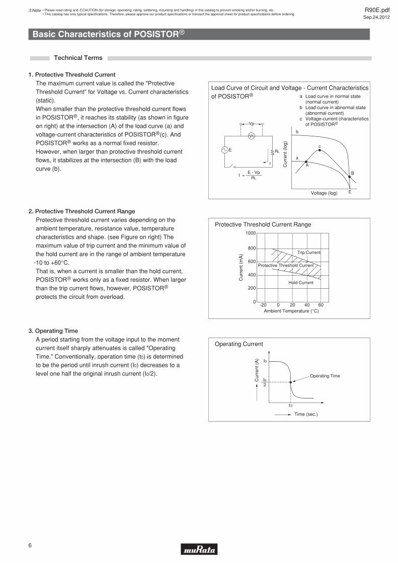
Load Curve of Circuit and Voltage - Current Characteristics of POSISTORr
1. Protective Threshold CurrentThe maximum current value is called the "Protective Threshold Current" for Voltage vs. Current characteristics (static).When smaller than the protective threshold current flows in POSISTORr, it reaches its stability (as shown in figure on right) at the intersection (A) of the load curve (a) and voltage-current characteristics of POSISTORr(c). And POSISTORr works as a normal fixed resistor.However, when larger than protective threshold current flows, it stabilizes at the intersection (B) with the load curve (b).
2. Protective Threshold Current RangeProtective threshold current varies depending on the ambient temperature, resistance value, temperature characteristics and shape. (see Figure on right) The maximum value of trip current and the minimum value of the hold current are in the range of ambient temperature
-10 to +60°C.That is, when a current is smaller than the hold current, POSISTORr works only as a fixed resistor. When larger than the trip current flows, however, POSISTORr protects the circuit from overload.
3. Operating TimeA period starting from the voltage input to the moment current itself sharply attenuates is called "Operating Time." Conventionally, operation time (t0) is determined to be the period until inrush current (I0) decreases to a level one half the original inrush current (I0/2).
E RL
Vp
I
I = E - Vp
RL
Load curve in normal state(normal current)Load curve in abnormal state(abnormal current)Voltage-current characteristicsof POSISTORr
a
b
c
c
a
b
Cur
rent
(lo
g)
A
B
EVoltage (log)
Protective Threshold Current Range1000
800
600
400
200
0-20 0 20 40 60
Ambient Temperature (°C)
Cur
rent
(m
A)
Protective Threshold Current
Hold Current
Trip Current
Operating Current
I0
I02
Cur
rent
(A
)
Time (sec.)
t0
Operating Time
Basic Characteristics of POSISTORr

R90E.pdfSep.24,2012
!Note • Please read rating and !CAUTION (for storage, operating, rating, soldering, mounting and handling) in this catalog to prevent smoking and/or burning, etc.• This catalog has only typical specifi cations. Therefore, please approve our product specifi cations or transact the approval sheet for product specifi cations before ordering.
7
What is the potential maximum voltage applied to POSISTORr?
How much current flows in the circuit at normal conditions?
How much current flows in the circuit at abnormal conditions?
Line Voltage 140V Usual Current 200mA Abnormal Current 580mA
Part NumberMax. Voltage
(V)
HoldCurrent at +60°C
(mA)
TripCurrent at -10°C
(mA)
Max. Current(A)
Resistance(at 25°C)
(ohm)
Thickness(T)
(mm)
PTGL18AR4R7M6B72B0 125 360 900 1.7 4.7 ±20% 5.5
PTGL18AR3R3M6B72B0 125 420 1050 2.0 3.3 ±20% 5.5
PTGL07AR330M6A51B0 140 100 230 0.5 33 ±20% 6.0
PTGL09AR220M6C61B0 140 140 330 1.0 22 ±20% 6.0
PTGL10AR150M6C61B0 140 170 400 1.0 15 ±20% 6.0
PTGL12AR100M6C01B0 140 220 510 1.0 10 ±20% 6.0
PTGL13AR6R8M6C01B0 140 290 670 1.0 6.8 ±20% 6.0
PTGL16AR5R6M6C01B0
PTGL12AR100M6C01B0 is the best selection in this case.
140 340 780 2.0 5.6 ±20% 6.0
BodyDiameter (D)
(mm)
18.5
18.5
7.4
9.6
11.6
13.0
14.0
17.0
o Confirmation Items
o Example
o Selection Standards
Line Maximum voltage V voltage of POSISTORr Abnormal Trip current of U current POSISTORr
Usual Hold current V current of POSISTORr
Selection Guide
Please confirm the parameters according to the following questions.The best selection is the product that matches three parameters.

R90E.pdfSep.24,2012
!Note • Please read rating and !CAUTION (for storage, operating, rating, soldering, mounting and handling) in this catalog to prevent smoking and/or burning, etc.• This catalog has only typical specifi cations. Therefore, please approve our product specifi cations or transact the approval sheet for product specifi cations before ordering.
Application Matrix
8
AV equipment
Information equipment
Communications equipment
Car electronics
Home electronicsHousehold equipment
Power supply
Plasma TVLCD TVProjection TVCATVSTBVideo cameraDigital cameraDVD recorderAudioElectric keyboard, Electronic music instrumentDigital mobile audioMD/CD playerTV gamePortable gameLaptopDesktop computerServerPrinterScannerLCD displayUSB access deviceHDDCD/DVD-ROM/RAMCopy machineElectronic dictionary/databookElectronic blackboardElectronic automatic exchangeTransmission equipmentPBXCordless telephone Fax machineModemCellular phoneHeadsetCellular phone base stationIntercomEngine control ECUDrive control ECUAir bagAnticollision radarABS/ESCInstrument/display panel, MeterRechargeable battery for EV/HEVCar air conditionerHID/LED headlight, AFSLED tail lightLED interior lightRetractable electric mirrorDoor lock, trunk openerPower seatShock absorberVICS, ETCBurglar alarmCar navigationCar audioRefrigerator Microwave, OvenElectric rice-cookerIH cooking deviceAir conditionerFan heaterCleanerClothes washer, cloth dryerVentilatorHot-water potIllumination deviceMassage chair, healthcare equipmentHot water spray toilet seatElectric power toolSwitching supplyInverter powerAC adapter, battery charger
Overcurrent Protection Overheat SensingChip type
PRFChip type
PRGLead type
PTGLLead type
PTFL, PTFMo
o
o
o
o
o
o
o
o
o
o
o
o
o
o
o
o
o
o
o
o
o
o
o
o
o
o
o
o
o
o
o
o
o
o
o
o
o
o
o
o
o
o
o
o
o
o
o
o
o
o
o
o
o
o
o
o
o
o
o
o
o
o
o
o
o
o
o
o
o
o
o
o
o
o
o
o
o
o
o
o
o
o
o
o
o
o
o
o
o
o
o
o
o
o
o
o
o
o
o
o
o
o
o
o
o
o
o
o
o
o
o
o
o
o
o
o
o
o
o
o
o
o
o
o
o
o
o
o
o
o
o
o
o
o
o
o
o
o
o
o
o
o
o
o
o
o
o
o
o
o
o
o
o
o
o
o
o
o
o
o
o
o
o
o
o
o
o
o
o
o
o
o
o
o
o
o
o
o
o
o
o
SeriesApplication

R90E.pdfSep.24,2012
!Note • Please read rating and !CAUTION (for storage, operating, rating, soldering, mounting and handling) in this catalog to prevent smoking and/or burning, etc.• This catalog has only typical specifi cations. Therefore, please approve our product specifi cations or transact the approval sheet for product specifi cations before ordering.
9
Application Part NumberMax.
Voltage(V)
Resistance(at 25 °C)
(ohm)
BodyDiameter
(mm)
Thickness(mm)
LeadSpace(mm)
LeadDiameter
(mm)
MoreDetails
PTGL13AR100H8B72B0
PTGL12AR150H8B72B0
PTGL14AR180M9C01B0
PTGL09AR250H8B52B0
PTGL09AR390M9C61B0
PTGL07AR560M9B51A0
PTGL07AR820M9B51A0
PTGL07AS121M0N51A0
PTGL07AS181M0N51A0
For highwattage power
supply
10 ±25% 14.0 6.0 7.5 0.60 page 57
15 ±25% 12.5 6.0 7.5 0.60 page 57
18 ±20% 15.7 6.5 10.0 0.65 page 57
25 ±25% 10.0 6.0 5.0 0.60 page 57
39 ±20% 10.0 6.5 6.5 0.65 page 57
56 ±20% 8.2 6.5 5.0 0.60 -
82 ±20% 8.2 6.5 5.0 0.60 -
120 ±20% 7.8 6.0 5.0 0.50 page 67
180 ±20% 7.8 6.0 5.0 0.50 page 67
For power supplyof electronicfluorescent
ballasts
265
280
Please ask for details.
POSISTORr is an integrated solution to work as both current limit resistor and overcurrent fuse. It works as a stable resistor in normal operation and protects itself against overcurrent situations.(1) High wattage power supply (flat display panels etc.)(2) Power supply for fluorescent lights(3) Other switching power supplies
c Inrush Current Limit for Power SupplyPOSISTORr Lead type: PTGL series1. Applications
(1) Protection against overcurrent situations(2) Automatic reset from protective trip mode(3) Space-saving(4) Various characteristics to meet a suitable resistance
value
2. Benefits
Choose an appropriate part number based on the resistance value required to the inrush current limit. Review the maximum voltage.
3. Recommended part numbers
Load
+
- Load
POSISTORr
+
-
Application Notes
Replacement idea for a resistor and fuse solution

R90E.pdfSep.24,2012
!Note • Please read rating and !CAUTION (for storage, operating, rating, soldering, mounting and handling) in this catalog to prevent smoking and/or burning, etc.• This catalog has only typical specifi cations. Therefore, please approve our product specifi cations or transact the approval sheet for product specifi cations before ordering.
10
Part NumberMax.
Voltage(V)
Max.Current
(A)
Trip Current(at -10 °C)
(mA)
Resistance(at +25 °C)
(ohm)
BodyDiameter
(mm)
Thickness(mm)
LeadDiameter
(mm)
MoreDetails
PTGL07BB220N0B52A0 250 0.5 300 22 ±30% 8.0 6.0 0.6 page 56
Hold Current(at +60 °C)
(mA)
90
LeadSpace(mm)
5.0
PTGL09AR250H8B52B0 265 1.0 330 25 ±25% 10.0 6.0 0.6 page 57118 5.0
PTGL09AR390N0B52A0 250 0.6 280 39 ±30% 10.0 6.0 0.6 page 56100 5.0
Please ask for details.
POSISTORr is an efficient device to protect a telephone line interface (SLIC: Subscriber-Loop-Interface-Circuit) against AC line contact.(1) Landline telephones or FAX machines(2) Telephone interface of STB, VoIP equipment(3) Any other equipment of communication facility having
a phone line interface
c Overcurrent Protection for Communication FacilityPOSISTORr Lead type: PTGL series1. Applications
(1) Automatic reset from protective trip up to 265V AC line contact
(2) Compatible with the 600V over voltage test by UL60950
(3) High resistance to the lighting surge (*A surge absorber is still required to protect SLIC)
2. Benefits
Choose an appropriate part number based on the hold current and on the resistance value required to the operation current of SLIC.
3. Recommended part numbers
SLIC SLIC
POSISTORrRing
Tip
Ring
Tip
Application Notes
Replacement idea for a current fuse.

R90E.pdfSep.24,2012
!Note • Please read rating and !CAUTION (for storage, operating, rating, soldering, mounting and handling) in this catalog to prevent smoking and/or burning, etc.• This catalog has only typical specifi cations. Therefore, please approve our product specifi cations or transact the approval sheet for product specifi cations before ordering.
11
Part NumberMax.
Voltage(V)
Max.Current
(A)
Hold Current(at +60 °C)
(mA)
Trip Current(at -10 °C)
(mA)
Resistance(at +25 °C)
(ohm)
Curie Point(°C) *
MoreDetails
PRG21BC0R2MM1RA 6 10 500 2000 0.2 ±20% 90 page 14
PRG21BC4R7MM1RA 30 5.0 100 400 4.7 ±20% 90 page 14
PRG21BC6R8MM1RA 30 3.5 80 320 6.8 ±20% 90 page 14
PRG21BC1R0MM1RA 12 10 220 850 1.0 ±20% 90 page 14
PRG21BC2R2MM1RA 16 6.5 150 600 2.2 ±20% 90 page 14
PRG21BC3R3MM1RA 20 6.0 120 480 3.3 ±20% 90 page 14
PRG21BC0R6MM1RA 6 10 285 1100 0.6 ±20% 90 page 14
*Curie Point means the temperature at which the resistance value reaches twice the resistance at 25°C.
Please ask for details.
POSISTORr is an effective current limit solution based on LED's allowable current and temperature characteristics.(1) LED lighting instruments(2) LED backlight of flat displays
c Current Limiter for LEDChip POSISTORr: PRG series1. Applications
(1) Higher LED brightness versus a fixed resistor. LED can work in the smaller series resistance with POSISTORr at normal operation temperature. The number of LEDs is possibly reduced.
(2) LED lifetime may be extended due to the current limiting function of the POSISTORr in cases of overheat or overcurrent situation.
(3) Small 0805 package allows the POSISTORr to be placed close to the LED. It offers accurate detection of ambient temperature near LED and increases flexibility of packaging.
2. Benefits
Choose an appropriate part number having max. voltage and resistance value. Review the protective threshold current range based on the operating current and temperature of the LED.
3. Recommended part numbers
IC
LED Driving Circuit LED CurrentLE
D C
urre
nt
Protected byPOSISTORr
Higher brightness vs. a fixed resistor
Current Limit by a fixed resistorAllowable LED
Working Zone
Ambient Temp.
IC
LED
Cur
rent
Allowable LEDWorking Zone
Ambient Temp.
Application Notes
See below figures.

R90E.pdfSep.24,2012
!Note • Please read rating and !CAUTION (for storage, operating, rating, soldering, mounting and handling) in this catalog to prevent smoking and/or burning, etc.• This catalog has only typical specifi cations. Therefore, please approve our product specifi cations or transact the approval sheet for product specifi cations before ordering.
12
Type Part NumberMax.
Voltage(V)
Max.Current
(A)
Hold Current(at +60 °C)
(mA)
Trip Current(at -10 °C)
(mA)
Resistance(at +25 °C)
(ohm)
Curie Point(°C) *
MoreDetails
PTGL04AS100K2N51B0
PTGL04AS100K2B51B0
PTGL05AS3R9K2B51B0
PTGL07AS2R7K2B51B0
PTGL07AS1R8K2B51B0
PTGL09AS1R2K2B51B0
PTGL12AS0R8K2B51B0
PTGL04AS100K3B51B0
PTGL05AS6R8K3B51B0
PTGL07AS3R3K3B51B0
PTGL09AS2R2K3B51B0
PTGL12AS1R2K3B51B0
PTGL07AR220M3P51B0
PTGL07AR8R2M3P51B0
PTGL09AR150M3B51B0
PTGL10AR3R9M3P51B0
PTGL09AR4R7M3B51B0
PTGL10AR3R9M3B51B0
PTGL14AR3R3M3B71B0
SMDtype
Leadtype
30
30
30
30
30
30
30
51
51
51
51
51
56
56
56
56
56
56
56
1.5
2.0
3.5
4.5
5.0
6.0
7.0
1.0
1.5
3.0
4.0
5.0
1.0
1.0
1.2
2.0
2.0
2.0
2.5
122
167
269
336
420
556
685
168
197
307
412
592
90
130
150
210
270
300
380
240
330
530
663
829
1097
1352
332
388
606
814
1168
240
350
400
550
700
800
980
10 ±10%
10 ±10%
3.9 ±10%
2.7 ±10%
1.8 ±10%
1.2 ±10%
0.8 ±10%
10 ±10%
6.8 ±10%
3.3 ±10%
2.2 ±10%
1.2 ±10%
22 ±20%
8.2 ±20%
15 ±20%
3.9 ±20%
4.7 ±20%
3.9 ±20%
3.3 ±20%
130
130
130
130
130
130
130
130
130
130
130
130
120
120
120
120
120
120
120
page 22
page 22
page 22
page 22
page 22
page 22
page 22
page 25
page 25
page 25
page 25
page 25
page 43
page 43
page 43
page 43
page 43
page 43
page 43
* Curie Point means the temperature at which the resistance value reaches twice the resistance at 25°C.
Please ask for details.
c Overheat/Overcurrent Protection for High Brightness LEDLeaded POSISTORr: PTGL series & Chip POSISTORr: PRG series1. Applications
2. Benefits
Choose an appropriate part number having max. voltage and resistance value. Review the protective threshold
current range based on the operating current and temperature of the LED.
3. Recommended part numbers
a) Overcurrent
b) Overheat
Resistance up !!
Heat up byovercurrent !
Resistance up !!
Heat up byoverheat situation !
Application Notes
POSISTORr is an effective solution to protect the LED against overheat and overcurrent situation. (1) LED lighting instruments (Appliances, Automotive etc.)
(1) Posistor installed in series with LED provides both overheat and overcurrent protection
(2) No additional driver IC or software required
(3) Automatic reset from protective trip mode(4) 0603 and 0805 SMD type available (smaller than
1/2W or 1W chip resistor)
PRG21BC0R2MM1RA 6 10 500 2000 0.2 ±20% 90 page 14
PRG21BC4R7MM1RA 30 5.0 100 400 4.7 ±20% 90 page 14
PRG21BC6R8MM1RA 30 3.5 80 320 6.8 ±20% 90 page 14
PRG21BC1R0MM1RA 12 10 220 850 1.0 ±20% 90 page 14
PRG21BC2R2MM1RA 16 6.5 150 600 2.2 ±20% 90 page 14
PRG21BC3R3MM1RA 20 6.0 120 480 3.3 ±20% 90 page 14
PRG21BC0R6MM1RA 6 10 285 1100 0.6 ±20% 90 page 14

POSISTORr for Circuit ProtectionOvercurrent Protection Chip Type
Overcurrent Protection device with resettable functionsuitable for current limiting resistor.This product is a chip type PTC thermistor for overcurrent protection that is suitable for thefollowing.· Countermeasure for short circuit testing· Current limiting resistor
c Features1. Rapid operation to protect the circuit in an overcurrent condition abnormality such as a short circuit. By removing the overcurrent condition, these products automatically return to the initial condition and can be used repeatedly.2. Suitable for countermeasure to short circuit test in safety standard.3. Stable resistance after operation due to ceramic PTC.4. Similar size (0603 size) is possible due to the large capacity for electric power.5. Possible to use these products as current limiting resistors with overcurrent protection functions6. The SMD type's small size and light weight are helpful in miniaturizing the circuit.
L
T
Part NumberL W T
Dimensions (mm)e g
1.6±0.15 0.8±0.15 0.8±0.15 0.1 to 0.6 -2.0±0.2 1.25±0.2 0.9±0.2 0.2 min. 0.5 min.2.0±0.2 1.25±0.2 1.25±0.2 0.2 min. 0.5 min.
PRG18_RBPRG21_RAPRG21_RK
W
e eg
Chip Type 0603(1608) Size
Part NumberMax.
Voltage(V)
Hold Current(at +60°C)
(mA)
Hold Current(at +25°C)
(mA)
Trip Current(at +25°C)
(mA)
Trip Current(at -10°C)
(mA)
Max.Current
(mA)
Resistance(at +25°C)
(ohm)
PRG18BB471MB1RB 24 7 10 21 25 60 470 ±20%
PRG18BB221MB1RB 24 10 14 29 35 130 220 ±20%
PRG18BB101MB1RB 24 15 21 45 55 300 100 ±20%
PRG18BB470MB1RB 24 20 29 61 75 630 47 ±20%
PRG18BB330MB1RB 24 25 36 71 85 900 33 ±20%
PRG18BC6R8MM1RB 20 80 120 260 320 3500 6.8 ±20%
PRG18BC4R7MM1RB 20 100 155 330 400 5000 4.7 ±20%
PRG18BC3R3MM1RB 16 120 180 400 480 6000 3.3 ±20%
PRG18BC2R2MM1RB 12 150 220 500 600 6500 2.2 ±20%
PRG18BC1R0MM1RB 6 220 330 740 850 7500 1.0 ±20%
Maximum Current shows typical capacities of the transformer which can be used.
This series is applied to refl ow soldering.
This series is recognized by UL.
R90E.pdfSep.24,2012
13
!Note • Please read rating and !CAUTION (for storage, operating, rating, soldering, mounting and handling) in this catalog to prevent smoking and/or burning, etc.• This catalog has only typical specifi cations. Therefore, please approve our product specifi cations or transact the approval sheet for product specifi cations before ordering.
1

Chip Type 0805(2012) Size
Part NumberMax.
Voltage(V)
Hold Current(at +60°C)
(mA)
Hold Current(at +25°C)
(mA)
Trip Current(at +25°C)
(mA)
Trip Current(at -10°C)
(mA)
Max.Current
(mA)
Resistance(at +25°C)
(ohm)
PRG21BB220MB1RK 20 30 44 91 110 1100 22 ±20%
PRG21BB150MB1RK 20 40 59 116 140 1600 15 ±20%
PRG21BC6R8MM1RA 30 80 120 260 320 5500 6.8 ±20%
PRG21BC4R7MM1RA 30 100 155 330 400 8000 4.7 ±20%
PRG21BC3R3MM1RA 20 120 180 400 480 6000 3.3 ±20%
PRG21BC2R2MM1RA 16 150 220 500 600 6500 2.2 ±20%
PRG21BC1R0MM1RA 12 220 330 740 850 10000 1.0 ±20%
PRG21BC0R6MM1RA 6 285 420 920 1100 10000 0.6 ±20%
PRG21BC0R2MM1RA 6 500 750 1620 2000 10000 0.2 ±20%
Maximum Current shows typical capacities of the transformer which can be used.
This series is applied to refl ow soldering.
This series is recognized by UL.
a
c
Solder resist
(in mm)b
LandChip
Part Number SolderingMethods Chip (LgW) a
Dimensions (mm)b c
1.6g0.8Reflow SolderingReflow Soldering
0.6-0.8 0.6-0.7 0.6-0.82.0g1.25 1.0-1.2 0.5-0.7 1.0-1.2
PRG18PRG21
c Standard Land Pattern Dimensions
40
30
20
10
–10 0 10 20 30 40 50 600
Ambient Temperature (°C)
Cur
rent
(m
A)
Trip current
Hold current
Protective threshold current
c Protective Threshold Current Range PRG18BB471MB1RB
60
40
20
–10 0 10 20 30 40 50 600
Ambient Temperature (°C)
Cur
rent
(m
A)
Trip current
Hold current
Protective threshold current
PRG18BB221MB1RB
Continued on the following page.
R90E.pdfSep.24,2012
14
!Note • Please read rating and !CAUTION (for storage, operating, rating, soldering, mounting and handling) in this catalog to prevent smoking and/or burning, etc.• This catalog has only typical specifi cations. Therefore, please approve our product specifi cations or transact the approval sheet for product specifi cations before ordering.
1

Continued from the preceding page.
80
60
40
20
–10 0 10 20 30 40 50 600
Ambient Temperature (°C)
Cur
rent
(m
A) Trip current
Hold current
Protective threshold current
c Protective Threshold Current Range PRG18BB101MB1RB
100
80
60
40
20
–10 0 10 20 30 40 50 600
Ambient Temperature (°C)
Cur
rent
(m
A)
Trip current
Hold current
Protective threshold current
PRG18BB470MB1RB
100
80
60
40
20
–10 0 10 20
Ambient Temperature (°C)
Cur
rent
(m
A)
30 40 50 600
Trip current
Hold current
Protective threshold current
PRG18BB330MB1RB
Cur
rent
(m
A)
–10
Ambient Temperature (°C)
0 10 20 4030 50 60
350
300
250
200
150
100
50
0
Protective threshold current
Hold current
Trip current
PRG18/21BC6R8M Type
Cur
rent
(m
A)
–10
Ambient Temperature (°C)
0 10 20 4030 50 60
450
400
350
300
250
200
150
100
50
0
Protective threshold current
Hold current
Trip current
PRG18/21BC4R7M Type
–10 0 10 20 30 40 50 600
100
200
300
400
500
600
700
Ambient Temperature (°C)
Cur
rent
(m
A)
Trip current
Hold current
Protective threshold current
PRG18/21BC3R3M Type
–10 0 10 20 30 40 50 600
100
200
300
400
500
600
700
Ambient Temperature (°C)
Cur
rent
(m
A)
Trip current
Hold current
Protective threshold current
PRG18/21BC2R2M Type
–10 0 10 20 30 40 50 600
200
400
600
800
1000
1200
Ambient Temperature (°C)
Cur
rent
(m
A)
Trip current
Hold current
Protective threshold current
PRG18/21BC1R0M Type
Continued on the following page.
R90E.pdfSep.24,2012
15
!Note • Please read rating and !CAUTION (for storage, operating, rating, soldering, mounting and handling) in this catalog to prevent smoking and/or burning, etc.• This catalog has only typical specifi cations. Therefore, please approve our product specifi cations or transact the approval sheet for product specifi cations before ordering.
1

Continued from the preceding page.
Cur
rent
(m
A)
–10
40
Ambient Temperature (°C)
0 10 20 4030 50 60
20
60
80
100
120
140
160
0
Protective threshold current range
Hold current
Trip current
c Protective Threshold Current Range PRG21BB220MB1RK
Cur
rent
(m
A)
–10
40
Ambient Temperature (°C)
0 10 20 4030 50 60
20
60
80
100
120
140
160
0
Protective threshold current range
Hold current
Trip current
PRG21BB150MB1RK
–10 0 10 20 30 40 50 600
200
400
600
800
1000
1200
Ambient Temperature (°C)
Cur
rent
(m
A)
Trip current
Hold current
Protective threshold current
PRG21BC0R6MM1RA
Cur
rent
(A
)
–10
Ambient Temperature (°C)
0 10 20 4030 50 600.0
0.5
1.0
1.5
2.0
2.5
3.0
Protective threshold current
Hold current
Trip current
PRG21BC0R2MM1RA
Y10°C
W25°C Ambient Temp.
W60°C
Overcurrent (mA)
Ope
ratin
g T
ime
(sec
.)
0 20 40 60 80 1000
5
10
15
20
c Operating Time (Typical Curve)PRG18BB471MB1RB
Y10°C
W25°C Ambient Temp.
W60°C
Overcurrent (mA)
Ope
ratin
g T
ime
(sec
.)
0 20 40 60 80 1000
5
10
15
20
PRG18BB221MB1RB
Continued on the following page.
R90E.pdfSep.24,2012
16
!Note • Please read rating and !CAUTION (for storage, operating, rating, soldering, mounting and handling) in this catalog to prevent smoking and/or burning, etc.• This catalog has only typical specifi cations. Therefore, please approve our product specifi cations or transact the approval sheet for product specifi cations before ordering.
1

Continued from the preceding page.
Y10°C
W25°C Ambient Temp.
W60°C
Overcurrent (mA)
Ope
ratin
g T
ime
(sec
.)
0 100 200 3000
20
15
10
5
c Operating Time (Typical Curve)PRG18BB101MB1RB
Y10°C
W25°C Ambient Temp.
W60°C
Overcurrent (mA)
Ope
ratin
g T
ime
(sec
.)
0 100 200 3000
20
15
10
5
PRG18BB470MB1RB
Y10°C
W25°C Ambient Temp.
W60°C
Overcurrent (mA)
Ope
ratin
g T
ime
(sec
.)
0 100 200 300 400 5000
20
15
10
5
PRG18BB330MB1RB
+60°C
+25°C Ambient Temp.
–10°C
Overcurrent (mA)
Ope
ratin
g T
ime
(sec
.)
0 200 400 600 800 1000
10.0
8.0
6.0
4.0
2.0
0.0
PRG18BC6R8MM1RB
+60°C
+25°C Ambient Temp.
–10°C
Overcurrent (mA)
Ope
ratin
g T
ime
(sec
.)
0 200 400 600 800 1000
10.0
8.0
6.0
4.0
2.0
0.0
PRG18BC4R7MM1RB
+60°C
+25°C Ambient Temp.
–10°C
Overcurrent (mA)
Ope
ratin
g T
ime
(sec
.)
0 500 1000 1500
10.0
8.0
6.0
4.0
2.0
0.0
PRG18BC3R3MM1RB
Continued on the following page.
R90E.pdfSep.24,2012
17
!Note • Please read rating and !CAUTION (for storage, operating, rating, soldering, mounting and handling) in this catalog to prevent smoking and/or burning, etc.• This catalog has only typical specifi cations. Therefore, please approve our product specifi cations or transact the approval sheet for product specifi cations before ordering.
1

Continued from the preceding page.
+60°C
+25°C Ambient Temp.
–10°C
Overcurrent (mA)
Ope
ratin
g T
ime
(sec
.)
0 500 1000 1500
10.0
8.0
6.0
4.0
2.0
0.0
c Operating Time (Typical Curve)PRG18BC2R2MM1RB
+60°C
+25°C Ambient Temp.
–10°C
Overcurrent (mA)
Ope
ratin
g T
ime
(sec
.)
0 1000 2000 3000500 1500 2500
10.0
8.0
6.0
4.0
2.0
0.0
PRG18BC1R0MM1RB
Y10°C
W25°C Ambient Temp.
W60°C
Overcurrent (mA)
Ope
ratin
g T
ime
(sec
.)
0 100 200 300 400 5000
20
15
10
5
PRG21BB220MB1RK
Y10°C
W25°C Ambient Temp.
W60°C
Overcurrent (mA)
Ope
ratin
g T
ime
(sec
.)
0 100 200 300 400 5000
20
15
10
5
PRG21BB150MB1RK
W60°C
W25°C Ambient Temp.
Y10°C
Overcurrent (mA)
Ope
ratin
g T
ime
(sec
.)
0 200 400 600 800 1000
10
8
6
4
2
0
PRG21BC6R8MM1RA
W60°C
W25°C Ambient Temp.
Y10°C
Overcurrent (mA)
Ope
ratin
g T
ime
(sec
.)
0 200 400 600 800 1000
10
8
6
4
2
0
PRG21BC4R7MM1RA
Continued on the following page.
R90E.pdfSep.24,2012
18
!Note • Please read rating and !CAUTION (for storage, operating, rating, soldering, mounting and handling) in this catalog to prevent smoking and/or burning, etc.• This catalog has only typical specifi cations. Therefore, please approve our product specifi cations or transact the approval sheet for product specifi cations before ordering.
1
Continued from the preceding page.
+60°C
+25°C Ambient Temp.
–10°C
Overcurrent (mA)
Ope
ratin
g T
ime
(sec
.)
0 500 1000 1500
10.0
8.0
6.0
4.0
2.0
0.0
c Operating Time (Typical Curve)PRG21BC3R3MM1RA
+60°C
+25°C Ambient Temp.
–10°C
Overcurrent (mA)
Ope
ratin
g T
ime
(sec
.)
0 500 1000 1500
10.0
8.0
6.0
4.0
2.0
0.0
PRG21BC2R2MM1RA
+60°C
+25°C Ambient Temp.
–10°C
Overcurrent (mA)
Ope
ratin
g T
ime
(sec
.)
0 500 1000 1500 25002000 3000
10.0
8.0
6.0
4.0
2.0
0.0
PRG21BC1R0MM1RA
+60°C
+25°C Ambient Temp.
–10°C
Overcurrent (mA)
Ope
ratin
g T
ime
(sec
.)
0 500 1000 1500 25002000 3000
10.0
8.0
6.0
4.0
2.0
0.0
PRG21BC0R6MM1RA
Y10°C
W25°C Ambient Temp.
W60°C
Overcurrent (A)
Ope
ratin
g T
ime
(sec
.)
0 1 2 3 4 5 6 7 8 9 100.0
0.1
0.2
0.3
0.4
0.5
0.6
0.7
0.8
0.9
1.0
PRG21BC0R2MM1RA
R90E.pdfSep.24,2012
19
!Note • Please read rating and !CAUTION (for storage, operating, rating, soldering, mounting and handling) in this catalog to prevent smoking and/or burning, etc.• This catalog has only typical specifi cations. Therefore, please approve our product specifi cations or transact the approval sheet for product specifi cations before ordering.
1

Chip Type Specifi cations and Test Methods
(*) Measure resistance after the test by applying voltage of less than 1.5Vdc by a direct current of less than 10mA after product is left at 25±2°C for 2 hours.
Above mentioned soldering in "4. Adhesive Strength" and "5. Vibration" is done under the following conditions at our site.#Glass-Epoxy PC board#Standard land dimension#Standard solder paste#Standard solder profileAbove conditions are mentioned in Notice.
JIS C 5102 term 9.1060±3°C (in air), PTC is applied maximum operating voltage for 1.5 hrs. on and 0.5 hrs. off. This cycle is repeated for 1000±10 hrs.
10 High Temperature LoadNormal appearanceResistance change: not to exceed ±20% (*)
JIS C 5102 term 9.540±2°C, 90-95%RH leave for 500±4 hrs.
9 Damp HeatNormal appearanceResistance change: not to exceed ±20% (*)
JIS C 5102 term 9.3Times: 5 cycles
8 Temperature CyclingNormal appearanceResistance change: not to exceed ±20% (*)
Solder: Sn 63%/Pb 37% (or 60/40%)Flux: Solder paste containing less than 0.2wt% of chlorine.Preheating: 150±5°C 3 mins.Peak temp.: 260±5°C 10±5 secs. (reflow)PCB: Glass Epoxy PCB (JIS C 6484)
7 Soldering Heat ResistanceNormal appearanceResistance change: not to exceed ±20% (*)
JIS C 5102 term 8.4Solder: Sn 63%/Pb 37% (or 60/40%)Solder temp: 230±5°CSoaking time: 3±0.5 secs.Soaking position: Until a whole electrode is soaked
6 SolderabilityMin. 75% electrode is covered with new solder.Resistance change: not to exceed ±20% (*)
JIS C 5102 term 8.2Soldered PTC to PCBVibration: A 10-55-10Hz (1 min.)Width: 1.5mmVibrate for 2 hrs. in each of 3 mutually perpendicular planes for a total of 6 hrs.
5 VibrationNormal appearance Resistance change: not to exceed ±20% (*)
EIAJ ET-7403 term 9Soldered PTC to PCB and add a force of 5.0N in the direction as shown below.
4 Adhesive Strength There is no sign of exfoliation on electrode.
We apply 120% of the maximum operating voltage to PTC by raising gradually for 180±5 secs. at 25°C. (A protective resistor is to be connected in series, and the inrush current through PTC must be limited below maximum rated value.)
3 Withstanding Voltage Without damage
After applying maximum operating voltage for 3 mins. and leaving for 2 hrs. in 25°C, measured by applying voltage of less than 1.5Vdc (by a direct current of less than 10mA).
2 Resistance Value (at 25°C)The resistance value should be within the specified tolerance.
Temperature range with maximum voltage applied to PTC.1 Operating Temp. -10 to 60°C
Step Temp. (°C)-20 +0, -3
Room temp.+85 +3, -0
Room temp.
Time (min.)30
10-1530
10-15
1234
c PRG18/21BB Series
No. Method of ExaminationRating ValueItem
Glass Epoxy PCBF=5.0N
F
F
PTC
R90E.pdfSep.24,2012
20
!Note • Please read rating and !CAUTION (for storage, operating, rating, soldering, mounting and handling) in this catalog to prevent smoking and/or burning, etc.• This catalog has only typical specifi cations. Therefore, please approve our product specifi cations or transact the approval sheet for product specifi cations before ordering.
1

Chip Type Specifi cations and Test Methods
(*) The resistance measurement after the test. After leaving for 24 hours or more in 25±2°C, it measures by 4 wire measuring methods using the direct-current terminal current of 10mA or less (0.1 or less Vdcs).
Above mentioned soldering in "4. Adhesive Strength" and "5. Vibration" is done under the following conditions at our site.#Glass-Epoxy PC board#Standard land dimension#Standard solder paste#Standard solder profileAbove conditions are mentioned in Notice.
60±3°C (in air), PTC is applied maximum operating voltage for 1.5 hrs. on and 0.5 hrs. off. This cycle is repeated for 500±10 hrs.
12 High Temperature Load
JIS C 5102 term 9.3Times: 5 cycles
11 Temperature Cycling
60±2°C, 90-95%RH leave for 500±4 hrs.10 Damp Heat
-10±3°C leave for 1000±12 hrs.9 Cold
60±3°C leave for 1000±12 hrs.8 Dry Heat
Normal appearanceResistance change: not to exceed ±20% (*)
Solder: Sn-3Ag-0.5CuFlax: Solder paste containing less than 0.2wt% of chlorine.Preheating: 150±5°C 3 mins.Peak temp.: 260±5°C 10±5 secs. (reflow)PCB: Glass Epoxy PCB (JIS C 6484)
7 Soldering Heat ResistanceNormal appearanceResistance change: not to exceed ±20% (*)
JIS C 5102 term 8.4Solder: Sn-3Ag-0.5CuSolder temp: 245±5°CSoaking time: 3±0.5 secs.Soaking position: Until a whole electrode is soaked.
6 SolderabilityMin. 75% electrode is covered with new solder.Resistance change: not to exceed ±20% (*)
JIS C 5102 term 8.2Soldered PTC to PCBVibration: A 10-55-10Hz (1 min.)Width: 1.5mm
Vibrate for 2 hrs. in each of 3 mutually perpendicular planes for a total of 6 hrs.
5 VibrationNormal appearance Resistance change: not to exceed ±20% (*)
EIAJ ET-7403 term 9Soldered PTC to PCB and add a force of 5.0N in the direction as shown below.
4 Adhesive Strength There is no sign of exfoliation on electrode.
We apply 120% of the maximum operating voltage to PTC by raising gradually for 180±5 secs. at 25°C. (A protective resistor is to be connected in series, and the inrush current through PTC must be limited below maximum rated value.)
3 Withstanding Voltage Without damage
After leaving for 24 hrs. or more in 25°C, it measures by 4 wire measuring methods using the direct-current terminal current of 10mA or less (0.1 or less Vdcs).
2 Resistance Value (at 25°C)The resistance value should be within the specified tolerance.
Temperature range with maximum voltage applied to PTC.1 Operating Temp. -10 to 60°C
Step Temp. (°C)-20 +0, -3
Room temp.+85 +3, -0
Room temp.
Time (min.)30
10-1530
10-15
1234
Glass Epoxy PCBF=5.0N
F
F
PTC
c PRG18/21BC Series
No. Method of ExaminationRating ValueItem
R90E.pdfSep.24,2012
21
!Note • Please read rating and !CAUTION (for storage, operating, rating, soldering, mounting and handling) in this catalog to prevent smoking and/or burning, etc.• This catalog has only typical specifi cations. Therefore, please approve our product specifi cations or transact the approval sheet for product specifi cations before ordering.
1
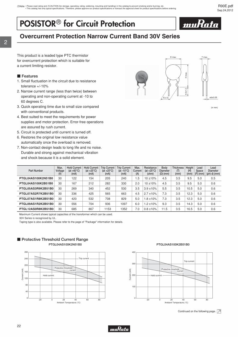
POSISTORr for Circuit ProtectionOvercurrent Protection Narrow Current Band 30V Series
This product is a leaded type PTC thermistor for overcurrent protection which is suitable for a current limiting resistor.
c Features1. Small fl uctuation in the circuit due to resistance tolerance +/-10%2. Narrow current range (less than twice) between operating and non-operating current at -10 to 60 degrees C.3. Quick operating time due to small size compared with conventional products.4. Best suited to meet the requirements for power supplies and motor protection. Error-free operations are assured by rush current.5. Circuit is protected until current is turned off.6. Restores the original low resistance value automatically once the overload is removed.7. Non-contact design leads to long life and no noise. Durable and strong against mechanical vibration and shock because it is a solid element.
F±1.5 ød±0.05
D max. T max.
H m
ax.
4.0±
1.5
(in mm)
Part NumberMax.
Voltage(V)
Hold Current(at +60°C)
(mA)
Hold Current(at +25°C)
(mA)
Trip Current(at +25°C)
(mA)
Trip Current(at -10°C)
(mA)
Max.Current
(A)
Resistance(at +25°C)
(ohm)
BodyDiameter(D) (mm)
Thickness(T)
(mm)
Height(H)
(mm)
LeadSpace
(F) (mm)
LeadDiameter
(phi d) (mm)
PTGL04AS100K2N51B0 30 122 154 205 240 1.5 10 ±10% 4.5 3.5 9.5 5.0 0.5
PTGL04AS100K2B51B0 30 167 212 282 330 2.0 10 ±10% 4.5 3.5 9.5 5.0 0.6
PTGL05AS3R9K2B51B0 30 269 340 452 530 3.5 3.9 ±10% 5.5 3.5 10.5 5.0 0.6
PTGL07AS2R7K2B51B0 30 336 425 565 663 4.5 2.7 ±10% 7.3 3.5 12.3 5.0 0.6
PTGL07AS1R8K2B51B0 30 420 532 708 829 5.0 1.8 ±10% 7.3 3.5 12.3 5.0 0.6
PTGL09AS1R2K2B51B0 30 556 704 936 1097 6.0 1.2 ±10% 9.3 3.5 14.3 5.0 0.6
PTGL12AS0R8K2B51B0 30 685 867 1153 1352 7.0 0.8 ±10% 11.5 3.5 16.5 5.0 0.6
Maximum Current shows typical capacities of the transformer which can be used.
30V Series is recognized by UL.
Taping type is also available. Please refer to the page of "Package" information for details.
0
40
80
120
160
200
240
280
-20 0 20 40 60 80Ambient Temperature (°C)
Cur
rent
(m
A)
Trip current
Hold current
Protective thresholdcurrent
c Protective Threshold Current RangePTGL04AS100K2N51B0
0
100
200
300
400
Cur
rent
(m
A)
-20 0 20 40 60 80Ambient Temperature (°C)
Trip current
Hold current
currentProtective threshold
PTGL04AS100K2B51B0
Continued on the following page.
R90E.pdfSep.24,2012
22
!Note • Please read rating and !CAUTION (for storage, operating, rating, soldering, mounting and handling) in this catalog to prevent smoking and/or burning, etc.• This catalog has only typical specifi cations. Therefore, please approve our product specifi cations or transact the approval sheet for product specifi cations before ordering.
2

Continued from the preceding page.
0
100
200
300
400
500
600
-20 0 20 40 60 80
Ambient Temperature (°C)
Cur
rent
(m
A)
Trip current
Hold current
Protective thresholdcurrent
c Protective Threshold Current RangePTGL05AS3R9K2B51B0
0
100
200
300
400
500
600
700
-20 0 20 40 60 80Ambient Temperature (°C)
Cur
rent
(m
A)
Trip current
Hold current
Protective thresholdcurrent
PTGL07AS2R7K2B51B0
0
200
400
600
800
1000
-20 0 20 40 60 80
Ambient Temperature (°C)
Cur
rent
(m
A)
Trip current
Hold current
Protective thresholdcurrent
PTGL07AS1R8K2B51B0
0
200
400
600
800
1000
1200
-20 0 20 40 60 80Ambient Temperature (°C)
Cur
rent
(m
A)
Trip current
Hold current
Protective thresholdcurrent
PTGL09AS1R2K2B51B0
0
400
800
1200
1600
-20 0 20 40 60 80Ambient Temperature (°C)
Cur
rent
(m
A)
Trip current
Hold current
Protective thresholdcurrent
PTGL12AS0R8K2B51B0
0.01
0.1
1
10
100
0.1 1 10Overcurrent (A)
Ope
ratin
g T
ime
(sec
.)
- 30°C- 10°C 25°C60°C85°C
Ambient Temp.
c Operating Time (Typical Curve)PTGL04AS100K2N51B0
0.01
0.1
1
10
100
0.1 1 10Overcurrent (A)
Ope
ratin
g T
ime
(sec
.) - 30°C- 10°C 25°C60°C85°C
Ambient Temp.
PTGL04AS100K2B51B0
Continued on the following page.
R90E.pdfSep.24,2012
23
!Note • Please read rating and !CAUTION (for storage, operating, rating, soldering, mounting and handling) in this catalog to prevent smoking and/or burning, etc.• This catalog has only typical specifi cations. Therefore, please approve our product specifi cations or transact the approval sheet for product specifi cations before ordering.
2

Continued from the preceding page.
0.01
0.1
1
10
100
0.1 1 10Overcurrent (A)
Ope
ratin
g T
ime
(sec
.)
- 30°C- 10°C 25°C60°C85°C
Ambient Temp.
c Operating Time (Typical Curve)PTGL05AS3R9K2B51B0
0.01
0.1
1
10
100
0.1 1 10Overcurrent (A)
Ope
ratin
g T
ime
(sec
.)
- 30°C- 10°C 25°C60°C85°C
Ambient Temp.
PTGL07AS2R7K2B51B0
0.1
1
10
100
0.1 1 10Overcurrent (A)
Ope
ratin
g T
ime
(sec
.)
- 30°C- 10°C 25°C60°C85°C
Ambient Temp.
PTGL07AS1R8K2B51B0
0.1
1
10
100
0.1 1 10Overcurrent (A)
Ope
ratin
g T
ime
(sec
.)
- 30°C- 10°C 25°C60°C85°C
Ambient Temp.
PTGL09AS1R2K2B51B0
0.1
1
10
100
0.1 1 10Overcurrent (A)
Ope
ratin
g T
ime
(sec
.)
Ambient Temp.
- 30°C- 10°C 25°C60°C85°C
PTGL12AS0R8K2B51B0
R90E.pdfSep.24,2012
24
!Note • Please read rating and !CAUTION (for storage, operating, rating, soldering, mounting and handling) in this catalog to prevent smoking and/or burning, etc.• This catalog has only typical specifi cations. Therefore, please approve our product specifi cations or transact the approval sheet for product specifi cations before ordering.
2

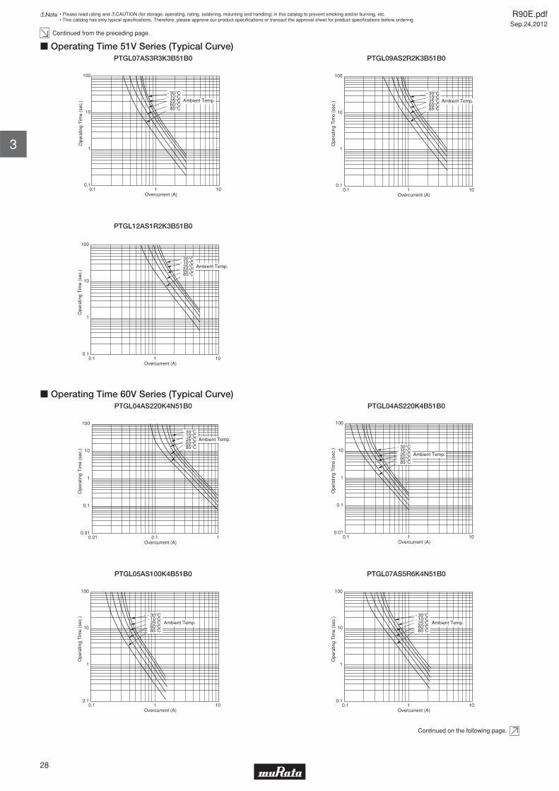
POSISTORr for Circuit ProtectionOvercurrent Protection Narrow Current Band 51/60V Series
This product is a leaded type PTC thermistor for overcurrent protection which is suitable for a current limiting resistor.
c Features1. Small fl uctuation in the circuit due to resistance tolerance +/-10%2. Narrow current range (less than twice) between operating and non-operating current at -10 to 60 degrees C.3. Quick operating time due to small size compared with conventional products.4. Best suited to meet the requirements for power supplies and motor protection. Error-free operations are assured by rush current.5. Circuit is protected until current is turned off.6. Restores the original low resistance value automatically once the overload is removed.7. Non-contact design leads to long life and no noise. Durable and strong against mechanical vibration and shock because it is a solid element.
F±1.5 ød±0.05
D max. T max.
H m
ax.
4.0±
1.5
(in mm)
Part NumberMax.
Voltage(V)
Hold Current(at +60°C)
(mA)
Hold Current(at +25°C)
(mA)
Trip Current(at +25°C)
(mA)
Trip Current(at -10°C)
(mA)
Max.Current
(A)
Resistance(at +25°C)
(ohm)
BodyDiameter(D) (mm)
Thickness(T)
(mm)
Height(H)
(mm)
LeadSpace
(F) (mm)
LeadDiameter
(phi d) (mm)
PTGL04AS100K3B51B0 51 168 213 283 332 1.0 10 ±10% 4.5 3.5 9.5 5.0 0.6
PTGL05AS6R8K3B51B0 51 197 249 331 388 1.5 6.8 ±10% 5.5 3.5 10.5 5.0 0.6
PTGL07AS3R3K3B51B0 51 307 389 517 606 3.0 3.3 ±10% 7.3 3.5 12.3 5.0 0.6
PTGL09AS2R2K3B51B0 51 412 522 694 814 4.0 2.2 ±10% 9.3 3.5 14.3 5.0 0.6
PTGL12AS1R2K3B51B0 51 592 749 996 1168 5.0 1.2 ±10% 11.5 3.5 16.5 5.0 0.6
PTGL04AS220K4N51B0 60 88 112 149 175 1.0 22 ±10% 4.5 3.5 9.5 5.0 0.5
PTGL04AS220K4B51B0 60 115 145 193 226 1.0 22 ±10% 4.5 3.5 9.5 5.0 0.6
PTGL05AS100K4B51B0 60 170 215 286 335 1.5 10 ±10% 5.5 3.5 10.5 5.0 0.6
PTGL07AS5R6K4N51B0 60 186 236 314 368 2.2 5.6 ±10% 7.3 3.5 12.3 5.0 0.5
PTGL07AS5R6K4B51B0 60 229 290 386 452 3.0 5.6 ±10% 7.3 3.5 12.3 5.0 0.6
PTGL09AS3R3K4B51B0 60 333 421 560 656 4.0 3.3 ±10% 9.3 3.5 14.3 5.0 0.6
PTGL12AS2R2K4B51B0 60 439 556 739 867 5.0 2.2 ±10% 11.5 3.5 16.5 5.0 0.6
Maximum Current shows typical capacities of the transformer which can be used.
51/60V Series are recognized by UL.
Taping type is also available. Please refer to the page of "Package" information for details.
R90E.pdfSep.24,2012
25
!Note • Please read rating and !CAUTION (for storage, operating, rating, soldering, mounting and handling) in this catalog to prevent smoking and/or burning, etc.• This catalog has only typical specifi cations. Therefore, please approve our product specifi cations or transact the approval sheet for product specifi cations before ordering.
3

0
100
200
300
400
-20 0 20 40 60 80Ambient Temperature (°C)
Cur
rent
(m
A)
Trip current
Hold current
Protective thresholdcurrent
c Protective Threshold Current Range (51V Series)PTGL04AS100K3B51B0
0
100
200
300
400
-20 0 20 40 60 80Ambient Temperature (°C)
Cur
rent
(m
A)
Trip current
Hold current
Protective thresholdcurrent
PTGL05AS6R8K3B51B0
0
100
200
300
400
500
600
700
-20 0 20 40 60 80Ambient Temperature (°C)
Cur
rent
(m
A)
Trip current
Hold current
Protective thresholdcurrent
PTGL07AS3R3K3B51B0
0
200
400
600
800
1000
-20 0 20 40 60 80Ambient Temperature (°C)
Cur
rent
(m
A)
Trip current
Hold current
Protective thresholdcurrent
PTGL09AS2R2K3B51B0
0
200
400
600
800
1000
1200
1400
-20 0 20 40 60 80Ambient Temperature (°C)
Cur
rent
(m
A)
Trip current
Hold current
Protective thresholdcurrent
PTGL12AS1R2K3B51B0
0
40
80
120
160
200
-20 0 20 40 60 80Ambient Temperature (°C)
Cur
rent
(m
A)
Trip current
Hold current
Protective thresholdcurrent
c Protective Threshold Current Range (60V Series)PTGL04AS220K4N51B0
0
40
80
120
160
200
240
-20 0 20 40 60 80Ambient Temperature (°C)
Cur
rent
(m
A)
Trip current
Hold current
Protective thresholdcurrent
PTGL04AS220K4B51B0
Continued on the following page.
R90E.pdfSep.24,2012
26
!Note • Please read rating and !CAUTION (for storage, operating, rating, soldering, mounting and handling) in this catalog to prevent smoking and/or burning, etc.• This catalog has only typical specifi cations. Therefore, please approve our product specifi cations or transact the approval sheet for product specifi cations before ordering.
3

Continued from the preceding page.
0
100
200
300
400
-20 0 20 40 60 80Ambient Temperature (°C)
Cur
rent
(m
A)
Trip current
Hold current
Protective thresholdcurrent
c Protective Threshold Current Range (60V Series)PTGL05AS100K4B51B0
0
100
200
300
400
-20 0 20 40 60 80Ambient Temperature (°C)
Cur
rent
(m
A)
Trip current
Hold current
Protective thresholdcurrent
PTGL07AS5R6K4N51B0
0
100
200
300
400
500
-20 0 20 40 60 80Ambient Temperature (°C)
Cur
rent
(m
A)
Trip current
Hold current
Protective thresholdcurrent
PTGL07AS5R6K4B51B0
0
100
200
300
400
500
600
700
-20 0 20 40 60 80Ambient Temperature (°C)
Cur
rent
(m
A)
Trip current
Hold current
Protective thresholdcurrent
PTGL09AS3R3K4B51B0
0
200
400
600
800
1000
-20 0 20 40 60 80Ambient Temperature (°C)
Cur
rent
(m
A)
Trip current
Hold current
Protective thresholdcurrent
PTGL12AS2R2K4B51B0
0.1
1
10
100
0.1 1 10Overcurrent (A)
Ope
ratin
g T
ime
(sec
.) - 30°C- 10°C 25°C60°C85°C
Ambient Temp.
c Operating Time 51V Series (Typical Curve)PTGL04AS100K3B51B0
0.1
1
10
100
0.1 1 10Overcurrent (A)
Ope
ratin
g T
ime
(sec
.)
- 30°C- 10°C 25°C60°C85°C
Ambient Temp.
PTGL05AS6R8K3B51B0
Continued on the following page.
R90E.pdfSep.24,2012
27
!Note • Please read rating and !CAUTION (for storage, operating, rating, soldering, mounting and handling) in this catalog to prevent smoking and/or burning, etc.• This catalog has only typical specifi cations. Therefore, please approve our product specifi cations or transact the approval sheet for product specifi cations before ordering.
3
Continued from the preceding page.
0.1
1
10
100
0.1 1 10Overcurrent (A)
Ope
ratin
g T
ime
(sec
.)
- 30°C- 10°C 25°C60°C85°C
Ambient Temp.
c Operating Time 51V Series (Typical Curve)PTGL07AS3R3K3B51B0
0.1
1
10
100
0.1 1 10Overcurrent (A)
Ope
ratin
g T
ime
(sec
.)
- 30°C- 10°C 25°C60°C85°C
Ambient Temp.
PTGL09AS2R2K3B51B0
0.1
1
10
100
0.1 1 10Overcurrent (A)
Ope
ratin
g T
ime
(sec
.)
Ambient Temp.
- 30°C- 10°C 25°C60°C85°C
PTGL12AS1R2K3B51B0
0.01
0.1
1
10
100
0.01 0.1 1Overcurrent (A)
Ope
ratin
g T
ime
(sec
.)
- 30°C- 10°C 25°C60°C85°C
Ambient Temp.
c Operating Time 60V Series (Typical Curve)PTGL04AS220K4N51B0
0.01
0.1
1
10
100
0.1 1 10Overcurrent (A)
Ope
ratin
g T
ime
(sec
.) - 30°C- 10°C 25°C60°C85°C
Ambient Temp.
PTGL04AS220K4B51B0
0.1
1
10
100
0.1 1 10Overcurrent (A)
Ope
ratin
g T
ime
(sec
.) - 30°C- 10°C 25°C60°C85°C
Ambient Temp.
PTGL05AS100K4B51B0
0.1
1
10
100
0.1 1 10Overcurrent (A)
Ope
ratin
g T
ime
(sec
.) - 30°C- 10°C 25°C60°C85°C
Ambient Temp.
PTGL07AS5R6K4N51B0
Continued on the following page.
R90E.pdfSep.24,2012
28
!Note • Please read rating and !CAUTION (for storage, operating, rating, soldering, mounting and handling) in this catalog to prevent smoking and/or burning, etc.• This catalog has only typical specifi cations. Therefore, please approve our product specifi cations or transact the approval sheet for product specifi cations before ordering.
3

Continued from the preceding page.
0.1
1
10
100
0.1 1 10Overcurrent (A)
Ope
ratin
g T
ime
(sec
.) - 30°C- 10°C 25°C60°C85°C
Ambient Temp.
c Operating Time 60V Series (Typical Curve)PTGL07AS5R6K4B51B0
0.1
1
10
100
0.1 1 10Overcurrent (A)
Ope
ratin
g T
ime
(sec
.) - 30°C- 10°C 25°C60°C85°C
Ambient Temp.
PTGL09AS3R3K4B51B0
0.1
1
10
100
0.1 1 10Overcurrent (A)
Ope
ratin
g T
ime
(sec
.) - 30°C- 10°C 25°C60°C85°C
Ambient Temp.
PTGL12AS2R2K4B51B0
R90E.pdfSep.24,2012
29
!Note • Please read rating and !CAUTION (for storage, operating, rating, soldering, mounting and handling) in this catalog to prevent smoking and/or burning, etc.• This catalog has only typical specifi cations. Therefore, please approve our product specifi cations or transact the approval sheet for product specifi cations before ordering.
3
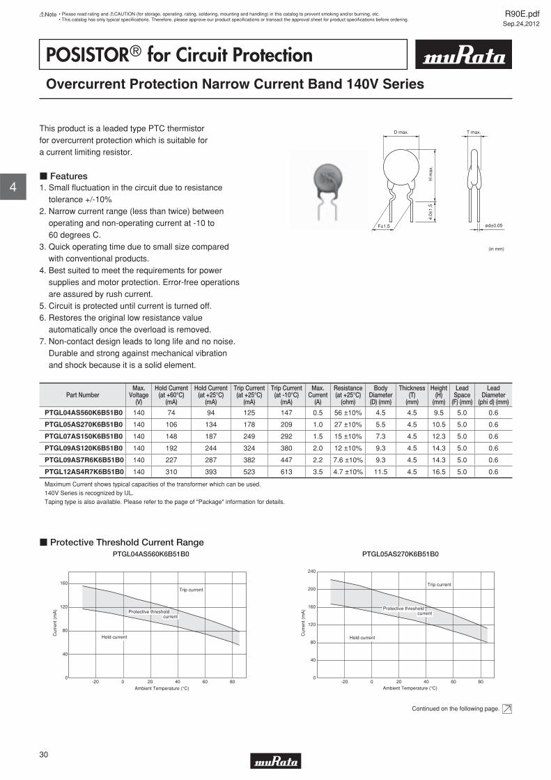
POSISTORr for Circuit ProtectionOvercurrent Protection Narrow Current Band 140V Series
This product is a leaded type PTC thermistor for overcurrent protection which is suitable for a current limiting resistor.
c Features1. Small fl uctuation in the circuit due to resistance tolerance +/-10%2. Narrow current range (less than twice) between operating and non-operating current at -10 to 60 degrees C.3. Quick operating time due to small size compared with conventional products.4. Best suited to meet the requirements for power supplies and motor protection. Error-free operations are assured by rush current.5. Circuit is protected until current is turned off.6. Restores the original low resistance value automatically once the overload is removed.7. Non-contact design leads to long life and no noise. Durable and strong against mechanical vibration and shock because it is a solid element.
F±1.5 ød±0.05
D max. T max.
H m
ax.
4.0±
1.5
(in mm)
Part NumberMax.
Voltage(V)
Hold Current(at +60°C)
(mA)
Hold Current(at +25°C)
(mA)
Trip Current(at +25°C)
(mA)
Trip Current(at -10°C)
(mA)
Max.Current
(A)
Resistance(at +25°C)
(ohm)
BodyDiameter(D) (mm)
Thickness(T)
(mm)
Height(H)
(mm)
LeadSpace
(F) (mm)
LeadDiameter
(phi d) (mm)
PTGL04AS560K6B51B0 140 74 94 125 147 0.5 56 ±10% 4.5 4.5 9.5 5.0 0.6
PTGL05AS270K6B51B0 140 106 134 178 209 1.0 27 ±10% 5.5 4.5 10.5 5.0 0.6
PTGL07AS150K6B51B0 140 148 187 249 292 1.5 15 ±10% 7.3 4.5 12.3 5.0 0.6
PTGL09AS120K6B51B0 140 192 244 324 380 2.0 12 ±10% 9.3 4.5 14.3 5.0 0.6
PTGL09AS7R6K6B51B0 140 227 287 382 447 2.2 7.6 ±10% 9.3 4.5 14.3 5.0 0.6
PTGL12AS4R7K6B51B0 140 310 393 523 613 3.5 4.7 ±10% 11.5 4.5 16.5 5.0 0.6
Maximum Current shows typical capacities of the transformer which can be used.
140V Series is recognized by UL.
Taping type is also available. Please refer to the page of "Package" information for details.
0
40
80
120
160
-20 0 20 40 60 80Ambient Temperature (°C)
Cur
rent
(m
A)
Trip current
Hold current
Protective thresholdcurrent
c Protective Threshold Current RangePTGL04AS560K6B51B0
0
40
80
120
160
200
240
-20 0 20 40 60 80Ambient Temperature (°C)
Cur
rent
(m
A)
Trip current
Hold current
Protective thresholdcurrent
PTGL05AS270K6B51B0
Continued on the following page.
R90E.pdfSep.24,2012
30
!Note • Please read rating and !CAUTION (for storage, operating, rating, soldering, mounting and handling) in this catalog to prevent smoking and/or burning, etc.• This catalog has only typical specifi cations. Therefore, please approve our product specifi cations or transact the approval sheet for product specifi cations before ordering.
4

Continued from the preceding page.
0
100
200
300
-20 0 20 40 60 80
Ambient Temperature (°C)
Cur
rent
(m
A)
Trip current
Protective thresholdcurrent
Hold current
c Protective Threshold Current RangePTGL07AS150K6B51B0
0
100
200
300
400
-20 0 20 40 60 80
Ambient Temperature (°C)
Cur
rent
(m
A)
Trip current
Hold current
Protective thresholdcurrent
PTGL09AS120K6B51B0
0
100
200
300
400
500
-20 0 20 40 60 80
Ambient Temperature (°C)
Cur
rent
(m
A)
Trip current
Hold current
Protective thresholdcurrent
PTGL09AS7R6K6B51B0
0
100
200
300
400
500
600
700
-20 0 20 40 60 80
Ambient Temperature (°C)
Cur
rent
(m
A)
Trip current
Hold current
Protective thresholdcurrent
PTGL12AS4R7K6B51B0
0.1
1
10
100
0.01 0.1 1Overcurrent (A)
Ope
ratin
g T
ime
(sec
.) Ambient Temp.
- 30°C- 10°C 25°C60°C85°C
c Operating Time (Typical Curve)PTGL04AS560K6B51B0
0.1
1
10
100
0.1 1 10Overcurrent (A)
Ope
ratin
g T
ime
(sec
.)
- 30°C- 10°C 25°C60°C85°C
Ambient Temp.
PTGL05AS270K6B51B0
0.1
1
10
100
0.1 1 10Overcurrent (A)
Ope
ratin
g T
ime
(sec
.)
- 30°C- 10°C 25°C60°C
Ambient Temp.
85°C
PTGL07AS150K6B51B0
0.1
1
10
100
0.1 1 10Overcurrent (A)
Ope
ratin
g T
ime
(sec
.) Ambient Temp.
- 30°C- 10°C 25°C60°C85°C
PTGL09AS120K6B51B0
Continued on the following page.
R90E.pdfSep.24,2012
31
!Note • Please read rating and !CAUTION (for storage, operating, rating, soldering, mounting and handling) in this catalog to prevent smoking and/or burning, etc.• This catalog has only typical specifi cations. Therefore, please approve our product specifi cations or transact the approval sheet for product specifi cations before ordering.
4

Continued from the preceding page.
0.1
1
10
100
0.1 1 10Overcurrent (A)
Ope
ratin
g T
ime
(sec
.)
- 30°C- 10°C 25°C60°C85°C
Ambient Temp.
c Operating Time (Typical Curve)PTGL09AS7R6K6B51B0
0.1
1
10
100
0.1 1 10Overcurrent (A)
Ope
ratin
g T
ime
(sec
.)
- 30°C- 10°C 25°C60°C85°C
Ambient Temp.
PTGL12AS4R7K6B51B0
R90E.pdfSep.24,2012
32
!Note • Please read rating and !CAUTION (for storage, operating, rating, soldering, mounting and handling) in this catalog to prevent smoking and/or burning, etc.• This catalog has only typical specifi cations. Therefore, please approve our product specifi cations or transact the approval sheet for product specifi cations before ordering.
4

POSISTORr for Circuit ProtectionOvercurrent Protection 16V Series
This low-voltage, low-resistance type "POSISTOR" is a circuit protector whose resistance value in normal operation is very low and in abnormal situations like motor lock or short circuit, will be increased to restrain overcurrent. This "POSISTOR" is most suitable for low-voltage circuits.
c Features1. Best suited to meet the requirements for power supplies and motor protection. Error-free operation is assured by rush current.2. Circuit is protected until current is turned off.3. Restores the original low resistance value automatically once the overload is removed.4. Non-contact design leads to long life and no noise. Durable and strong against mechanical vibration and shock because it is a solid element.
F±1.5 ød±0.05
D max. T max.
H m
ax.
4.0±
1.5
(in mm)
Part NumberMax.
Voltage(V)
Hold Current(at +60°C)
(mA)
Hold Current(at +25°C)
(mA)
Trip Current(at +25°C)
(mA)
Trip Current(at -10°C)
(mA)
Max.Current
(A)
Resistance(at +25°C)
(ohm)
BodyDiameter(D) (mm)
Thickness(T)
(mm)
Height(H)
(mm)
LeadSpace
(F) (mm)
LeadDiameter
(phi d) (mm)
PTGL05AR1R0M1B51B0 16 370 470 880 1040 2.0 1.0 ±20% 6.0 3.5 9.5 5.0 0.6
PTGL06AR0R8M1B51B0 16 400 505 955 1120 3.0 0.8 ±20% 6.5 3.5 10.0 5.0 0.6
PTGL07ARR47M1B51B0 16 560 705 1310 1570 5.0 0.47 ±20% 7.5 3.5 12.0 5.0 0.6
PTGL09ARR33M1B51B0 16 680 875 1625 1900 7.0 0.33 ±20% 9.0 3.5 14.0 5.0 0.6
PTGL10ARR27M1B51B0 16 800 1025 1900 2250 8.0 0.27 ±20% 10.1 3.5 15.0 5.0 0.6
PTGL12AR0R2M1B51B0 16 1000 1300 2410 2800 9.0 0.2 ±20% 11.3 3.5 16.0 5.0 0.6
PTGL14ARR15M1B51B0 16 1200 1545 2855 3360 10 0.15 ±20% 13.5 3.5 18.5 5.0 0.6
Maximum Current shows typical capacities of the transformer which can be used.
Taping type is also available(except PTGL14ARR15M1B51B0). Please refer to the page of "Package" information for details.
1400
1200
1000
800
600
400
200
0
Ambient Temperature (°C)
Cur
rent
(m
A)
-20 -10 0 10 20 30 40 50 60 70 80
Trip current
Hold current
Protective threshold current
c Protective Threshold Current Range (16V Series) PTGL05AR1R0M1B51B0
1400
1200
1000
800
600
400
200
0
Ambient Temperature (°C)
Cur
rent
(m
A)
-20 -10 0 10 20 30 40 50 60 70 80
Trip current
Hold current
Protective threshold current
PTGL06AR0R8M1B51B0
Continued on the following page.
R90E.pdfSep.24,2012
33
!Note • Please read rating and !CAUTION (for storage, operating, rating, soldering, mounting and handling) in this catalog to prevent smoking and/or burning, etc.• This catalog has only typical specifi cations. Therefore, please approve our product specifi cations or transact the approval sheet for product specifi cations before ordering.
5

Continued from the preceding page.
2000
1800
1600
1400
1200
1000
800
600
400
200
0
Ambient Temperature (°C)
Cur
rent
(m
A)
-20 -10 0 10 20 30 40 50 60 70 80
Protective threshold current
Trip current
Hold current
c Protective Threshold Current Range (16V Series) PTGL07ARR47M1B51B0
2600
2400
2200
2000
1800
1600
1400
1200
1000
800
600
400
200
0
Ambient Temperature (°C)
Cur
rent
(m
A)
-20 -10 0 10 20 30 40 50 60 70 80
Trip current
Hold current
Protective threshold current
PTGL09ARR33M1B51B0
3000
2800
2600
2400
2200
2000
1800
1600
1400
1200
1000
800
600
400
200
0
Ambient Temperature (°C)
Cur
rent
(m
A)
-20 -10 0 10 20 30 40 50 60 70 80
Trip current
Hold current
Protective threshold current
PTGL10ARR27M1B51B0
4000
3500
3000
2500
2000
1500
1000
500
0
Ambient Temperature (°C)
Cur
rent
(m
A)
-20 -10 0 10 20 30 40 50 60 70 80
Trip current
Hold current
Protective threshold current
PTGL12AR0R2M1B51B0
4000
3500
3000
2500
2000
1500
1000
500
0
Ambient Temperature (°C)
Cur
rent
(m
A)
-20 -10 0 10 20 30 40 50 60 70 80
Trip current
Hold current
Protective threshold current
PTGL14ARR15M1B51B0
100.0
10.0
1.0
0.10.1 1 10 100
Overcurrent (A)
Ope
ratin
g T
ime
(sec
.)
-10°C+25°C+60°C
Ambient Temp.
c Operating Time 16V Series (Typical Curve)PTGL05AR1R0M1B51B0
100.0
10.0
1.0
0.10.1 1 10 100
Overcurrent (A)
Ope
ratin
g T
ime
(sec
.)
-10°C+25°C+60°C
Ambient Temp.
PTGL06AR0R8M1B51B0
Continued on the following page.
R90E.pdfSep.24,2012
34
!Note • Please read rating and !CAUTION (for storage, operating, rating, soldering, mounting and handling) in this catalog to prevent smoking and/or burning, etc.• This catalog has only typical specifi cations. Therefore, please approve our product specifi cations or transact the approval sheet for product specifi cations before ordering.
5

Continued from the preceding page.
100.0
10.0
1.0
0.10.1 1 10 100
Overcurrent (A)
Ope
ratin
g T
ime
(sec
.)
-10°C+25°C+60°C
Ambient Temp.
c Operating Time 16V Series (Typical Curve)PTGL07ARR47M1B51B0
100.0
10.0
1.0
0.10.1 1 10 100
Overcurrent (A)
Ope
ratin
g T
ime
(sec
.)
-10°C+25°C+60°C
Ambient Temp.
PTGL09ARR33M1B51B0
100.0
10.0
1.0
0.10.1 1 10 100
Overcurrent (A)
Ope
ratin
g T
ime
(sec
.)
-10°C+25°C+60°C
Ambient Temp.
PTGL10ARR27M1B51B0
100.0
10.0
1.0
0.10.1 1 10 100
Overcurrent (A)
Ope
ratin
g T
ime
(sec
.)
-10°C+25°C+60°C
Ambient Temp.
PTGL12AR0R2M1B51B0
100.0
10.0
1.0
0.10.1 1 10 100
Overcurrent (A)
Ope
ratin
g T
ime
(sec
.)
-10°C+25°C+60°C
Ambient Temp.
PTGL14ARR15M1B51B0
R90E.pdfSep.24,2012
35
!Note • Please read rating and !CAUTION (for storage, operating, rating, soldering, mounting and handling) in this catalog to prevent smoking and/or burning, etc.• This catalog has only typical specifi cations. Therefore, please approve our product specifi cations or transact the approval sheet for product specifi cations before ordering.
5

POSISTORr for Circuit ProtectionOvercurrent Protection 24/30/32V Series
The safety resistor "POSISTOR" is most suited to meet the requirements of the safety standard short-circuit testssuch as IEC, VDE, BS, UL, CSA, etc., worldwide.
c Features1. Best suited to meet the requirements of the short- circuit test. Quick response compared with current fuse and resistor and error-free operation are assured.2. Small size save board space. Capable of being mounted anywhere because replacement is not required.3. Actuates by excessive current during the short- circuit test to restrain abnormal heat generation in other circuit components and printed boards. This state will be maintained until the abnormal state is removed or power is turned off to reset the "POSISTOR" to the original state. Surface temperature of "POSISTOR" is kept low, below a certain value, during the actuation.4. Non-contact design leads to long life and no noise. Durable and strong against mechanical vibration and shock because it is a solid element.
D max.
4.0±
1.5
6.0
max
.
F±1.5 (in mm)
T max.
ød±0.05
Part NumberMax.
Voltage(V)
Hold Current(at +60°C)
(mA)
Hold Current(at +25°C)
(mA)
Trip Current(at +25°C)
(mA)
Trip Current(at -10°C)
(mA)
Max.Current
(A)
Resistance(at +25°C)
(ohm)
BodyDiameter(D) (mm)
Thickness(T)
(mm)
LeadSpace
(F) (mm)
LeadDiameter
(phi d) (mm)
PTGL07BD100N2B51B0 24 80 124 251 320 2.0 10 ±30% 7.4 4.0 5.0 0.6
PTGL07BD6R8N2B51B0 24 90 139 296 370 2.0 6.8 ±30% 7.4 4.0 5.0 0.6
PTGL09BD4R7N2B51B0 24 120 216 398 500 2.0 4.7 ±30% 9.5 4.0 5.0 0.6
PTGL09BD3R3N2B51B0 24 140 248 461 580 2.0 3.3 ±30% 9.5 4.0 5.0 0.6
PTGL09BD2R2N2B51B0 24 180 326 431 710 2.0 2.2 ±30% 9.5 4.0 5.0 0.6
PTGL04AR130H2B51B0 30 145 180 350 400 0.7 13 ±25% 5.5 4.0 5.0 0.6
PTGL07AR4R6H2B51B0 30 250 340 610 700 2.0 4.6 ±25% 7.4 4.0 5.0 0.6
PTGL09AR1R8H2B51B0 30 410 510 970 1120 3.0 1.8 ±25% 9.5 4.0 5.0 0.6
PTGL12AR1R2H2B51B0 30 520 645 1225 1420 4.3 1.2 ±25% 12.0 4.0 5.0 0.6
PTGL13AR0R8H2B71B0 30 680 870 1600 1900 5.5 0.8 ±25% 13.5 4.0 7.5 0.6
PTGL07BD470N3B51B0 32 30 55 115 140 1.5 47 ±30% 7.4 4.0 5.0 0.6
PTGL07BD330N3B51B0 32 40 60 135 170 1.5 33 ±30% 7.4 4.0 5.0 0.6
PTGL07BD220N3B51B0 32 45 75 160 200 1.5 22 ±30% 7.4 4.0 5.0 0.6
PTGL07BD150N3B51B0 32 60 100 195 240 1.5 15 ±30% 7.4 4.0 5.0 0.6
Maximum Current shows typical capacities of the transformer which can be used.
24/30/32V Series are recognized by UL (except PTGL13AR0R8H2B71B0).
Only PTGL_51B0 series are available in taping type (except PTGL12AR1R2H2B51B0). Please refer to the page of "Package" information for details.
R90E.pdfSep.24,2012
36
!Note • Please read rating and !CAUTION (for storage, operating, rating, soldering, mounting and handling) in this catalog to prevent smoking and/or burning, etc.• This catalog has only typical specifi cations. Therefore, please approve our product specifi cations or transact the approval sheet for product specifi cations before ordering.
6

Cur
rent
(m
A)
200
20
600
400
Ambient Temperature (°C)
0–20 0 40 60
Trip current
Protective threshold current
Hold current
c Protective Threshold Current Range (24V Series) PTGL07BD100N2B51B0
Cur
rent
(m
A)
200
20
600
400
Ambient Temperature (°C)
0–20 0 40 60
Trip current
Protective threshold current
Hold current
PTGL07BD6R8N2B51B0C
urre
nt (
mA
)
200
20
600
400
Ambient Temperature (°C)
0–20 0 40 60
Trip current
Protective threshold current
Hold current
PTGL09BD4R7N2B51B0
Cur
rent
(m
A)
200
20
600
400
Ambient Temperature (°C)
0–20 0 40 60
Trip current
Protective threshold current
Hold current
PTGL09BD3R3N2B51B0
Cur
rent
(m
A)
500
20
1000
Ambient Temperature (°C)
0–20 0 40 60
Trip current
Protective threshold current
Hold current
1500
PTGL09BD2R2N2B51B0
Cur
rent
(m
A)
200
20
400
Ambient Temperature (°C)
0–20 0 40 60
Trip current
Protective threshold current
Hold current
600
c Protective Threshold Current Range (30V Series)PTGL04AR130H2B51B0
Cur
rent
(m
A)
20
800
600
400
Ambient Temperature (°C)
0–20 0 40 60
Trip current
Protective threshold current
Hold current
200
PTGL07AR4R6H2B51B0
Continued on the following page.
R90E.pdfSep.24,2012
37
!Note • Please read rating and !CAUTION (for storage, operating, rating, soldering, mounting and handling) in this catalog to prevent smoking and/or burning, etc.• This catalog has only typical specifi cations. Therefore, please approve our product specifi cations or transact the approval sheet for product specifi cations before ordering.
6

Continued from the preceding page.
Cur
rent
(m
A)
500
20
1000
Ambient Temperature (°C)
0–20 0 40 60
Trip current
Protective threshold current
Hold current
1500
c Protective Threshold Current Range (30V Series)PTGL09AR1R8H2B51B0
Cur
rent
(m
A)
500
20
1000
Ambient Temperature (°C)
0–20 0 40 60
Trip current
Protective threshold current
Hold current
1500
PTGL12AR1R2H2B51B0C
urre
nt (
mA
)
500
20
2000
1500
1000
Ambient Temperature (°C)
0 –20 0 40 60
Trip current
Protective threshold current
Hold current
PTGL13AR0R8H2B71B0
Cur
rent
(m
A)
100
20
300
200
Ambient Temperature (°C)
0–20 0 40 60
Trip current
Protective threshold current
Hold current
c Protective Threshold Current Range (32V Series)PTGL07BD470N3B51B0
Cur
rent
(m
A)
100
20
300
200
Ambient Temperature (°C)
0–20 0 40 60
Trip current
Protective threshold current
Hold current
PTGL07BD330N3B51B0
Cur
rent
(m
A)
100
20
300
200
Ambient Temperature (°C)
0–20 0 40 60
Trip current
Protective threshold current
Hold current
PTGL07BD220N3B51B0
Cur
rent
(m
A)
100
20
300
200
Ambient Temperature (°C)
0–20 0 40 60
Trip current
Protective threshold current
Hold current
PTGL07BD150N3B51B0
R90E.pdfSep.24,2012
38
!Note • Please read rating and !CAUTION (for storage, operating, rating, soldering, mounting and handling) in this catalog to prevent smoking and/or burning, etc.• This catalog has only typical specifi cations. Therefore, please approve our product specifi cations or transact the approval sheet for product specifi cations before ordering.
6

Ope
ratin
g T
ime
(sec
.)
0Overcurrent (A)
25
20
15
10
5
0
–10°C 25°C Ambient Temp. 60°C
0.5 1.0 1.5 2.0
c Operating Time 24V Series (Typical Curve)PTGL07BD100N2B51B0
Ope
ratin
g T
ime
(sec
.)
0Overcurrent (A)
25
20
15
10
5
0
–10°C 25°C Ambient Temp. 60°C
0.5 1.0 1.5 2.0
PTGL07BD6R8N2B51B0
Ope
ratin
g T
ime
(sec
.)
0Overcurrent (A)
25
20
15
10
5
0
–10°C 25°C Ambient Temp. 60°C
0.5 1.0 1.5 2.0
PTGL09BD4R7N2B51B0
Ope
ratin
g T
ime
(sec
.)
0Overcurrent (A)
25
20
15
10
5
0
–10°C 25°C Ambient Temp. 60°C
0.5 1.0 1.5 2.0
30
PTGL09BD3R3N2B51B0
Ope
ratin
g T
ime
(sec
.)
0Overcurrent (A)
70
60
50
40
30
20
10
0
–10°C 25°C Ambient Temp. 60°C
0.5 1.0 1.5 2.0
PTGL09BD2R2N2B51B0
R90E.pdfSep.24,2012
39
!Note • Please read rating and !CAUTION (for storage, operating, rating, soldering, mounting and handling) in this catalog to prevent smoking and/or burning, etc.• This catalog has only typical specifi cations. Therefore, please approve our product specifi cations or transact the approval sheet for product specifi cations before ordering.
6

Ope
ratin
g T
ime
(sec
.)
0Overcurrent (A)
70
60
50
40
30
20
10
00.2 0.6
Ambient Temp.
0.4
–10°C 25°C 60°C
c Operating Time 30V Series (Typical Curve)PTGL04AR130H2B51B0
Ope
ratin
g T
ime
(sec
.)
0Overcurrent (A)
70
60
50
40
30
20
10
0
–10°C 25°C Ambient Temp. 60°C
0.2 0.4 0.6 0.8 1.0
PTGL07AR4R6H2B51B0
Ope
ratin
g T
ime
(sec
.)
0Overcurrent (A)
70
60
50
40
30
20
10
0
–10°C 25°C Ambient Temp. 60°C
1.0 2.0 3.0
PTGL09AR1R8H2B51B0
Ope
ratin
g T
ime
(sec
.)
0Overcurrent (A)
70
60
50
40
30
20
10
0
–10°C 25°C Ambient Temp. 60°C
1.0 2.0 3.0 4.0
PTGL12AR1R2H2B51B0
Ope
ratin
g T
ime
(sec
.)
0Overcurrent (A)
70
60
50
40
30
20
10
0
–10°C 25°C Ambient Temp. 60°C
1.0 2.0 3.0 4.0 5.0
PTGL13AR0R8H2B71B0
R90E.pdfSep.24,2012
40
!Note • Please read rating and !CAUTION (for storage, operating, rating, soldering, mounting and handling) in this catalog to prevent smoking and/or burning, etc.• This catalog has only typical specifi cations. Therefore, please approve our product specifi cations or transact the approval sheet for product specifi cations before ordering.
6

Ope
ratin
g T
ime
(sec
.)
0Overcurrent (A)
25
20
15
10
5
0
–10°C 25°C Ambient Temp. 60°C
0.5 1.0 1.5
c Operating Time 32V Series (Typical Curve)PTGL07BD470N3B51B0
Ope
ratin
g T
ime
(sec
.)
0Overcurrent (A)
25
20
15
10
5
0
–10°C 25°C Ambient Temp. 60°C
0.5 1.0 1.5
PTGL07BD330N3B51B0
Ope
ratin
g T
ime
(sec
.)
0Overcurrent (A)
25
20
15
10
5
0
–10°C 25°C Ambient Temp. 60°C
0.5 1.0 1.5
PTGL07BD220N3B51B0
Ope
ratin
g T
ime
(sec
.)
0Overcurrent (A)
25
20
15
10
5
0
–10°C 25°C Ambient Temp. 60°C
0.5 1.0 1.5
PTGL07BD150N3B51B0
AC100V
PTH
Short
R3
B
R4
R1
R2
+
–
C
E
c Application Circuit(1) Short - Circuit Test of Transistor
AC100V
Short
PTH
R1
(2) Short - Circuit Test of Diode
Continued on the following page.
R90E.pdfSep.24,2012
41
!Note • Please read rating and !CAUTION (for storage, operating, rating, soldering, mounting and handling) in this catalog to prevent smoking and/or burning, etc.• This catalog has only typical specifi cations. Therefore, please approve our product specifi cations or transact the approval sheet for product specifi cations before ordering.
6
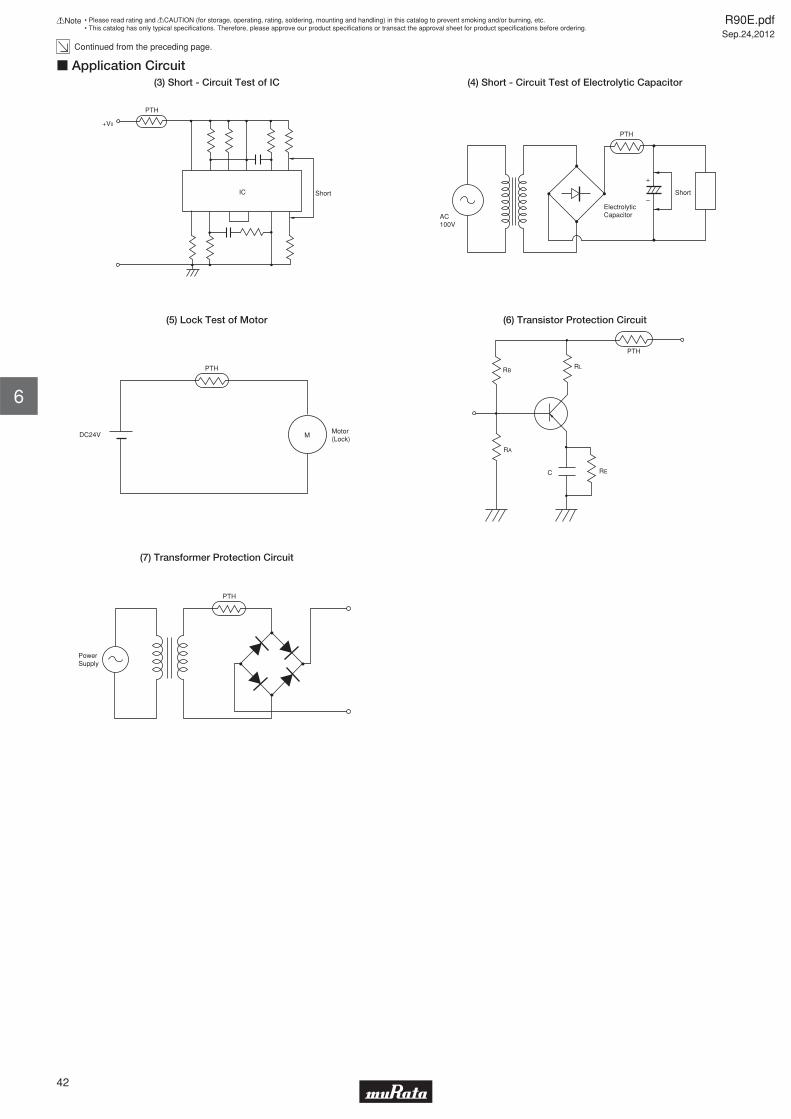
Continued from the preceding page.
PTH
Short
+V0
IC
c Application Circuit(3) Short - Circuit Test of IC
AC100V
PTH
Short
ElectrolyticCapacitor
+
–
(4) Short - Circuit Test of Electrolytic Capacitor
PTH
Motor(Lock)
DC24V M
(5) Lock Test of Motor
RL
RA
RE
RB
C
PTH
(6) Transistor Protection Circuit
PowerSupply
PTH
(7) Transformer Protection Circuit
R90E.pdfSep.24,2012
42
!Note • Please read rating and !CAUTION (for storage, operating, rating, soldering, mounting and handling) in this catalog to prevent smoking and/or burning, etc.• This catalog has only typical specifi cations. Therefore, please approve our product specifi cations or transact the approval sheet for product specifi cations before ordering.
6

POSISTORr for Circuit ProtectionOvercurrent Protection 56/80V Series
"POSISTOR" is a circuit protector whose resistance value in normal operation is very low and in abnormal situations like overcurrent or overheating, will be increased to restrain overcurrent. "POSISTOR" can be used for overcurrent protection against current fuse or temperature fuse, due to its ability to return to its initial condition when overcurrent is removed.
c Features1. Best suited to meet the requirements for power supplies and motor protection. Error-free operations are assured by rush current.2. Circuit is protected until current is turned off.3. Restores the original low resistance value automatically once the overload is removed.4. Non-contact design leads to long life and no noise. Durable and strong against mechanical vibration and shock because it is a solid element.
c Applications1. DC cooling fan motors in offi ce equipment, e.g., computers, facsimiles, fl oppy disk drives and power units.2. DC drive motors in VTRs and cassette tape recorders. Power transformers (at secondary winding)
F±1.5 ød±0.05
D max. T max.
6.0
max
.4.
0±1.
5
(in mm)
Part NumberMax.
Voltage(V)
Hold Current(at +60°C)
(mA)
Hold Current(at +25°C)
(mA)
Trip Current(at +25°C)
(mA)
Trip Current(at -10°C)
(mA)
Max.Current
(A)
Resistance(at +25°C)
(ohm)
BodyDiameter(D) (mm)
Thickness(T)
(mm)
LeadSpace
(F) (mm)
LeadDiameter
(phi d) (mm)
PTGL07AR220M3P51B0 56 90 115 205 240 1.0 22 ±20% 7.4 4.0 5.0 0.6
PTGL07AR8R2M3P51B0 56 130 165 300 350 1.0 8.2 ±20% 7.4 4.0 5.0 0.6
PTGL09AR150M3B51B0 56 150 190 340 400 1.2 15 ±20% 9.5 4.0 5.0 0.6
PTGL10AR3R9M3P51B0 56 210 260 470 550 2.0 3.9 ±20% 10.5 4.0 5.0 0.6
PTGL09AR4R7M3B51B0 56 270 350 600 700 2.0 4.7 ±20% 9.5 4.0 5.0 0.6
PTGL10AR3R9M3B51B0 56 300 390 680 800 2.0 3.9 ±20% 10.5 4.0 5.0 0.6
PTGL14AR3R3M3B71B0 56 380 490 830 980 2.5 3.3 ±20% 14.5 4.0 7.5 0.6
PTGL05AR550H4P51B0 80 50 62 115 135 0.7 55 ±25% 5.5 4.5 5.0 0.6
PTGL07AR250H4B51B0 80 110 140 260 300 1.0 25 ±25% 7.4 4.5 5.0 0.6
PTGL09AR9R4H4B51B0 80 190 240 450 530 3.0 9.4 ±25% 9.5 4.5 5.0 0.6
PTGL12AR5R6H4B71B0 80 270 350 650 760 4.3 5.6 ±25% 12.0 4.5 7.5 0.6
PTGL13AR3R7H4B71B0 80 310 405 750 860 5.5 3.7 ±25% 13.5 4.5 7.5 0.6
Maximum Current shows typical capacities of the transformer which can be used.
Please contact us for UL recognized products.
Only PTGL_51B0 type is available in taping type. Please refer to the page of "Package" information for details.
R90E.pdfSep.24,2012
43
!Note • Please read rating and !CAUTION (for storage, operating, rating, soldering, mounting and handling) in this catalog to prevent smoking and/or burning, etc.• This catalog has only typical specifi cations. Therefore, please approve our product specifi cations or transact the approval sheet for product specifi cations before ordering.
7

Cur
rent
(m
A)
–20
100
Ambient Temperature (°C)0 20 40 60 80
200
300
0
Trip current
Hold current
Protective threshold current
c Protective Threshold Current Range (56V Series) PTGL07AR220M3P51B0
Cur
rent
(m
A)
–20Ambient Temperature (°C)
0 20 40 60 800
Trip current
Hold current
Protective threshold current
100
200
300
400
500
PTGL07AR8R2M3P51B0
Cur
rent
(m
A)
–20Ambient Temperature (°C)
0 20 40 60 800
Trip current
Hold current
Protective threshold current
100
200
300
400
500
PTGL09AR150M3B51B0
Cur
rent
(m
A)
–20Ambient Temperature (°C)
0 20 40 60 800
Trip current
Hold current
Protective threshold current
800
600
400
200
PTGL10AR3R9M3P51B0
Cur
rent
(m
A)
–20Ambient Temperature (°C)
0 20 40 60 800
Trip current
Hold current
Protective threshold current
800
600
400
200
PTGL09AR4R7M3B51B0
Cur
rent
(m
A)
–20Ambient Temperature (°C)
0 20 40 60 800
Trip current
Hold current
Protective threshold current
1000
800
600
400
200
PTGL10AR3R9M3B51B0
Cur
rent
(m
A)
–20Ambient Temperature (°C)
0 20 40 60 800
Trip current
Hold current
Protective threshold current
1500
1000
500
PTGL14AR3R3M3B71B0
R90E.pdfSep.24,2012
44
!Note • Please read rating and !CAUTION (for storage, operating, rating, soldering, mounting and handling) in this catalog to prevent smoking and/or burning, etc.• This catalog has only typical specifi cations. Therefore, please approve our product specifi cations or transact the approval sheet for product specifi cations before ordering.
7

Cur
rent
(m
A)
50
20
100
Ambient Temperature (°C)
0–20 0 40 60
Trip current
Protective threshold current
Hold current
150
c Protective Threshold Current Range (80V Series)PTGL05AR550H4P51B0
Cur
rent
(m
A)
100
20
400
300
200
Ambient Temperature (°C)
0–20 0 40 60
Trip current
Protective threshold current
Hold current
PTGL07AR250H4B51B0C
urre
nt (
mA
)
200
20
800
600
400
Ambient Temperature (°C)
0 –20 0 40 60
Trip current
Protective threshold current
Hold current
PTGL09AR9R4H4B51B0
Cur
rent
(m
A)
200
20
800
600
400
Ambient Temperature (°C)
0 –20 0 40 60
Trip current
Protective threshold current
Hold current
PTGL12AR5R6H4B71B0
Cur
rent
(m
A)
500
20
1000
Ambient Temperature (°C)
0–20 0 40 60
Trip current
Protective threshold current
Hold current
1500
PTGL13AR3R7H4B71B0
R90E.pdfSep.24,2012
45
!Note • Please read rating and !CAUTION (for storage, operating, rating, soldering, mounting and handling) in this catalog to prevent smoking and/or burning, etc.• This catalog has only typical specifi cations. Therefore, please approve our product specifi cations or transact the approval sheet for product specifi cations before ordering.
7

Ope
ratin
g T
ime
(sec
.)
0Overcurrent (A)
70
60
50
40
30
20
10
0
–10°C 25°C Ambient Temp. 60°C
0.2 0.4 0.6 0.8
c Operating Time 56V Series (Typical Curve) PTGL07AR220M3P51B0
Ope
ratin
g T
ime
(sec
.)
0Overcurrent (A)
0
–10°C 25°C Ambient Temp. 60°C
10
20
30
40
50
0.5 1.0 1.5 2.0
PTGL07AR8R2M3P51B0
Ope
ratin
g T
ime
(sec
.)
0Overcurrent (A)
70
60
50
40
30
20
10
0
–10°C 25°C 60°C Ambient Temp.
0.2 0.4 0.6 0.8
PTGL09AR150M3B51B0
Ope
ratin
g T
ime
(sec
.)
0Overcurrent (A)
0
–10°C 25°C Ambient Temp. 60°C
5
10
15
20
25
1 2 3 4
PTGL10AR3R9M3P51B0
Ope
ratin
g T
ime
(sec
.)
0Overcurrent (A)
0
–10°C 25°C Ambient Temp. 60°C
5
10
15
20
25
1 2 3 4
PTGL09AR4R7M3B51B0
Ope
ratin
g T
ime
(sec
.)
0Overcurrent (A)
0
–10°C 25°C Ambient Temp. 60°C
5
10
15
20
25
1 2 3 4
PTGL10AR3R9M3B51B0
Continued on the following page.
R90E.pdfSep.24,2012
46
!Note • Please read rating and !CAUTION (for storage, operating, rating, soldering, mounting and handling) in this catalog to prevent smoking and/or burning, etc.• This catalog has only typical specifi cations. Therefore, please approve our product specifi cations or transact the approval sheet for product specifi cations before ordering.
7
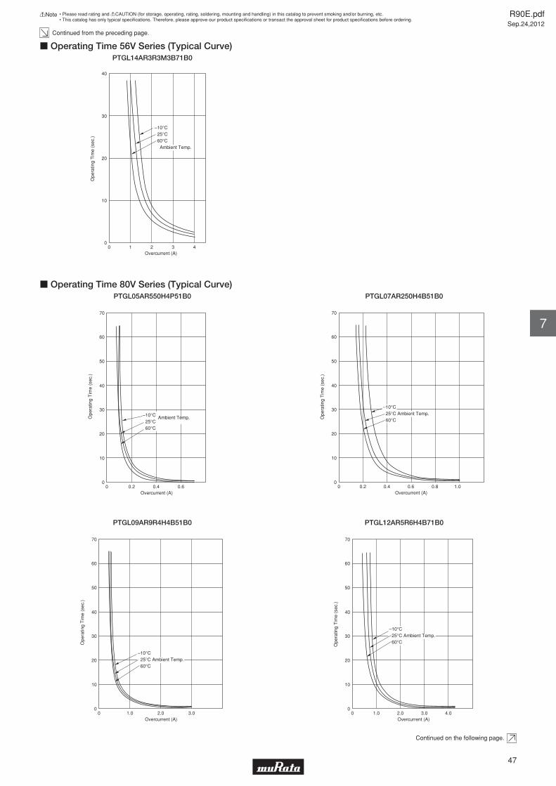
Continued from the preceding page.
Ope
ratin
g T
ime
(sec
.)
0Overcurrent (A)
40
30
20
10
01 2 3 4
–10°C 25°C 60°C Ambient Temp.
c Operating Time 56V Series (Typical Curve) PTGL14AR3R3M3B71B0
Ope
ratin
g T
ime
(sec
.)
0Overcurrent (A)
70
60
50
40
30
20
10
0
–10°C 25°C 60°C
0.2 0.6
Ambient Temp.
0.4
c Operating Time 80V Series (Typical Curve)PTGL05AR550H4P51B0
Ope
ratin
g T
ime
(sec
.)
0Overcurrent (A)
70
60
50
40
30
20
10
0
–10°C 25°C Ambient Temp. 60°C
0.2 0.4 0.6 0.8 1.0
PTGL07AR250H4B51B0
Ope
ratin
g T
ime
(sec
.)
0Overcurrent (A)
70
60
50
40
30
20
10
0
–10°C 25°C Ambient Temp. 60°C
1.0 2.0 3.0
PTGL09AR9R4H4B51B0
Ope
ratin
g T
ime
(sec
.)
0Overcurrent (A)
70
60
50
40
30
20
10
0
–10°C 25°C Ambient Temp. 60°C
1.0 2.0 3.0 4.0
PTGL12AR5R6H4B71B0
Continued on the following page.
R90E.pdfSep.24,2012
47
!Note • Please read rating and !CAUTION (for storage, operating, rating, soldering, mounting and handling) in this catalog to prevent smoking and/or burning, etc.• This catalog has only typical specifi cations. Therefore, please approve our product specifi cations or transact the approval sheet for product specifi cations before ordering.
7

Continued from the preceding page.
Ope
ratin
g T
ime
(sec
.)
0Overcurrent (A)
70
60
50
40
30
20
10
0
–10°C 25°C Ambient Temp. 60°C
1.0 2.0 3.0 4.0 5.0
c Operating Time 80V Series (Typical Curve)PTGL13AR3R7H4B71B0
MotorPower Supply
M
PTH
c Application Circuit(1) DC Motor Protection Circuit
RL
RA
RE
RB
C
PTH
(2) Transistor Protection Circuit
PowerSupply
PTH
(3) Transformer Protection Circuit
R90E.pdfSep.24,2012
48
!Note • Please read rating and !CAUTION (for storage, operating, rating, soldering, mounting and handling) in this catalog to prevent smoking and/or burning, etc.• This catalog has only typical specifi cations. Therefore, please approve our product specifi cations or transact the approval sheet for product specifi cations before ordering.
7
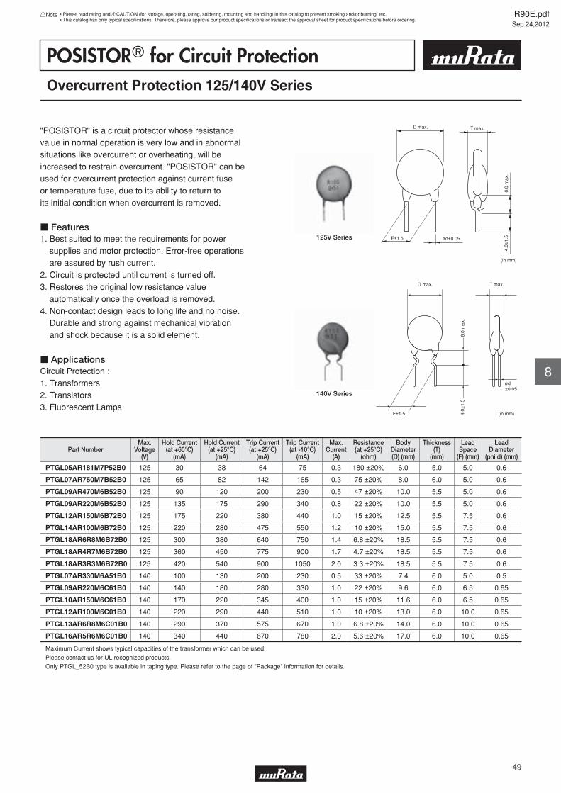
POSISTORr for Circuit ProtectionOvercurrent Protection 125/140V Series
"POSISTOR" is a circuit protector whose resistance value in normal operation is very low and in abnormal situations like overcurrent or overheating, will be increased to restrain overcurrent. "POSISTOR" can be used for overcurrent protection against current fuse or temperature fuse, due to its ability to return to its initial condition when overcurrent is removed.
c Features1. Best suited to meet the requirements for power supplies and motor protection. Error-free operations are assured by rush current.2. Circuit is protected until current is turned off.3. Restores the original low resistance value automatically once the overload is removed.4. Non-contact design leads to long life and no noise. Durable and strong against mechanical vibration and shock because it is a solid element.
c ApplicationsCircuit Protection : 1. Transformers2. Transistors3. Fluorescent Lamps
F±1.5 ød±0.05
D max. T max.
6.0
max
.4.
0±1.
5
(in mm)
125V Series
D max.
4.0±
1.5
6.0
max
.
F±1.5 (in mm)
T max.
ød±0.05
140V Series
Part NumberMax.
Voltage(V)
Hold Current(at +60°C)
(mA)
Hold Current(at +25°C)
(mA)
Trip Current(at +25°C)
(mA)
Trip Current(at -10°C)
(mA)
Max.Current
(A)
Resistance(at +25°C)
(ohm)
BodyDiameter(D) (mm)
Thickness(T)
(mm)
LeadSpace
(F) (mm)
LeadDiameter
(phi d) (mm)
PTGL05AR181M7P52B0 125 30 38 64 75 0.3 180 ±20% 6.0 5.0 5.0 0.6
PTGL07AR750M7B52B0 125 65 82 142 165 0.3 75 ±20% 8.0 6.0 5.0 0.6
PTGL09AR470M6B52B0 125 90 120 200 230 0.5 47 ±20% 10.0 5.5 5.0 0.6
PTGL09AR220M6B52B0 125 135 175 290 340 0.8 22 ±20% 10.0 5.5 5.0 0.6
PTGL12AR150M6B72B0 125 175 220 380 440 1.0 15 ±20% 12.5 5.5 7.5 0.6
PTGL14AR100M6B72B0 125 220 280 475 550 1.2 10 ±20% 15.0 5.5 7.5 0.6
PTGL18AR6R8M6B72B0 125 300 380 640 750 1.4 6.8 ±20% 18.5 5.5 7.5 0.6
PTGL18AR4R7M6B72B0 125 360 450 775 900 1.7 4.7 ±20% 18.5 5.5 7.5 0.6
PTGL18AR3R3M6B72B0 125 420 540 900 1050 2.0 3.3 ±20% 18.5 5.5 7.5 0.6
PTGL07AR330M6A51B0 140 100 130 200 230 0.5 33 ±20% 7.4 6.0 5.0 0.5
PTGL09AR220M6C61B0 140 140 180 280 330 1.0 22 ±20% 9.6 6.0 6.5 0.65
PTGL10AR150M6C61B0 140 170 220 345 400 1.0 15 ±20% 11.6 6.0 6.5 0.65
PTGL12AR100M6C01B0 140 220 290 440 510 1.0 10 ±20% 13.0 6.0 10.0 0.65
PTGL13AR6R8M6C01B0 140 290 370 575 670 1.0 6.8 ±20% 14.0 6.0 10.0 0.65
PTGL16AR5R6M6C01B0 140 340 440 670 780 2.0 5.6 ±20% 17.0 6.0 10.0 0.65
Maximum Current shows typical capacities of the transformer which can be used.
Please contact us for UL recognized products.
Only PTGL_52B0 type is available in taping type. Please refer to the page of "Package" information for details.
R90E.pdfSep.24,2012
49
!Note • Please read rating and !CAUTION (for storage, operating, rating, soldering, mounting and handling) in this catalog to prevent smoking and/or burning, etc.• This catalog has only typical specifi cations. Therefore, please approve our product specifi cations or transact the approval sheet for product specifi cations before ordering.
8
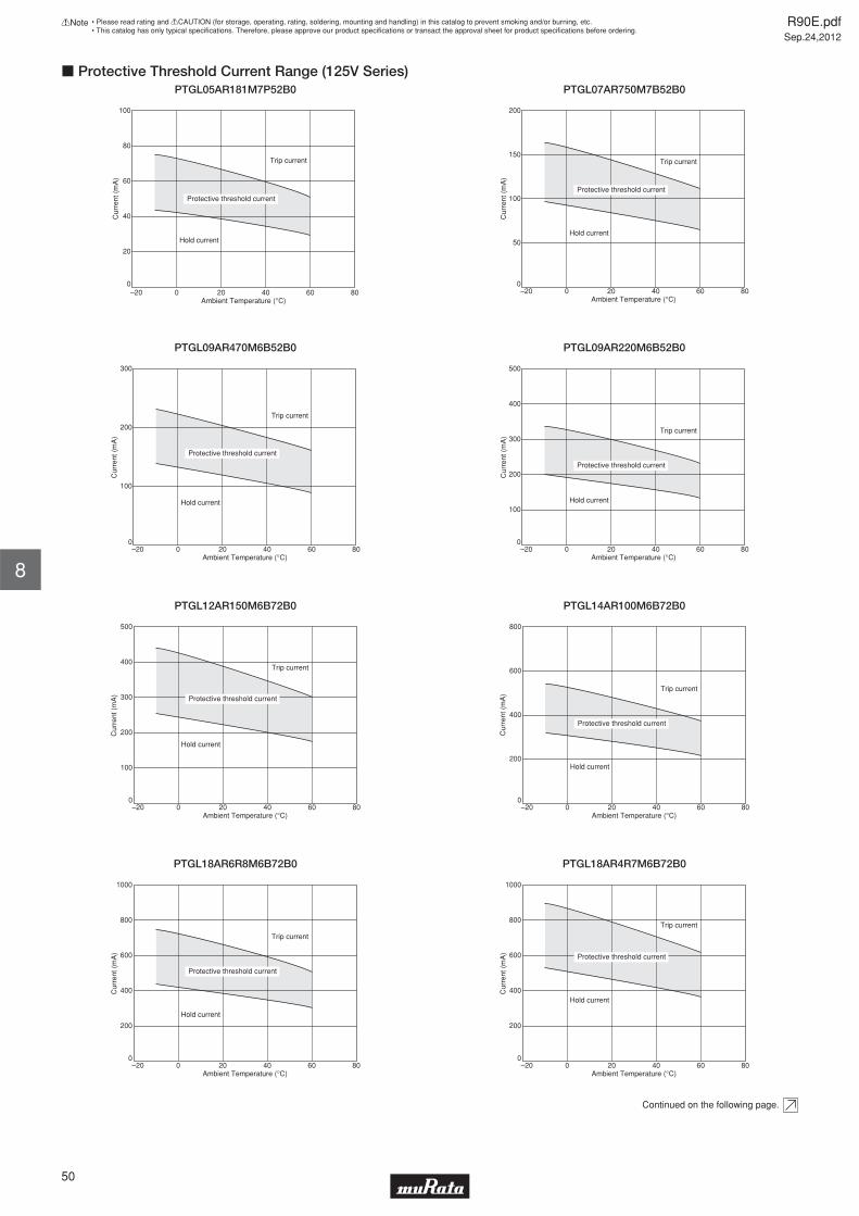
Cur
rent
(m
A)
–20Ambient Temperature (°C)
0 20 40 60 800
Trip current
Hold current
Protective threshold current
100
80
60
40
20
c Protective Threshold Current Range (125V Series)PTGL05AR181M7P52B0
Cur
rent
(m
A)
–20Ambient Temperature (°C)
0 20 40 60 800
Trip current
Hold current
Protective threshold current
200
150
100
50
PTGL07AR750M7B52B0
Cur
rent
(m
A)
–20
100
Ambient Temperature (°C)0 20 40 60 80
200
300
0
Trip current
Hold current
Protective threshold current
PTGL09AR470M6B52B0
Cur
rent
(m
A)
–20Ambient Temperature (°C)
0 20 40 60 800
Trip current
Hold current
Protective threshold current
100
200
300
400
500
PTGL09AR220M6B52B0
Cur
rent
(m
A)
–20Ambient Temperature (°C)
0 20 40 60 800
Trip current
Hold current
Protective threshold current
100
200
300
400
500
PTGL12AR150M6B72B0
Cur
rent
(m
A)
–20Ambient Temperature (°C)
0 20 40 60 800
Trip current
Hold current
Protective threshold current
800
600
400
200
PTGL14AR100M6B72B0
Cur
rent
(m
A)
–20Ambient Temperature (°C)
0 20 40 60 800
Trip current
Hold current
Protective threshold current
1000
800
600
400
200
PTGL18AR6R8M6B72B0
Cur
rent
(m
A)
–20Ambient Temperature (°C)
0 20 40 60 800
Trip current
Hold current
Protective threshold current
1000
800
600
400
200
PTGL18AR4R7M6B72B0
Continued on the following page.
R90E.pdfSep.24,2012
50
!Note • Please read rating and !CAUTION (for storage, operating, rating, soldering, mounting and handling) in this catalog to prevent smoking and/or burning, etc.• This catalog has only typical specifi cations. Therefore, please approve our product specifi cations or transact the approval sheet for product specifi cations before ordering.
8

Continued from the preceding page.
Cur
rent
(m
A)
–20Ambient Temperature (°C)
0 20 40 60 800
Trip current
Hold current
Protective threshold current
1200
1000
800
600
400
200
c Protective Threshold Current Range (125V Series)PTGL18AR3R3M6B72B0
Cur
rent
(m
A)
100
20
200
Ambient Temperature (°C)
0–20 0 40 60
Trip current
Protective threshold current
Hold current
300
80
c Protective Threshold Current Range (140V Series)PTGL07AR330M6A51B0
Cur
rent
(m
A)
200
20
800
600
400
Ambient Temperature (°C)
0 –20 0 40 60
Trip current
Protective threshold current
Hold current
80
PTGL09AR220M6C61B0
Cur
rent
(m
A)
200
20
800
600
400
Ambient Temperature (°C)
0 –20 0 40 60
Trip current
Protective threshold current
Hold current
80
PTGL10AR150M6C61B0
Cur
rent
(m
A)
200
20
800
600
400
Ambient Temperature (°C)
0 –20 0 40 60
Trip current
Protective threshold current
Hold current
80
PTGL12AR100M6C01B0
Cur
rent
(m
A)
200
20
800
600
400
Ambient Temperature (°C)
0 –20 0 40 60
Trip current
Protective threshold current
Hold current
80
PTGL13AR6R8M6C01B0
Cur
rent
(m
A)
200
20
800
600
400
Ambient Temperature (°C)
0 –20 0 40 60
Trip current
Protective threshold current
Hold current
80
PTGL16AR5R6M6C01B0
R90E.pdfSep.24,2012
51
!Note • Please read rating and !CAUTION (for storage, operating, rating, soldering, mounting and handling) in this catalog to prevent smoking and/or burning, etc.• This catalog has only typical specifi cations. Therefore, please approve our product specifi cations or transact the approval sheet for product specifi cations before ordering.
8

Ope
ratin
g T
ime
(sec
.)
0Overcurrent (A)
70
60
50
40
30
20
10
0
–10°C 25°C Ambient Temp. 60°C
0.1 0.2 0.3
c Operating Time 125V Series (Typical Curve)PTGL05AR181M7P52B0
Ope
ratin
g T
ime
(sec
.)
0Overcurrent (A)
70
60
50
40
30
20
10
00.1 0.2 0.3 0.4
–10°C 25°C 60°C Ambient Temp.
PTGL07AR750M7B52B0
Ope
ratin
g T
ime
(sec
.)
0Overcurrent (A)
60
50
40
30
20
10
0
–10°C 25°C Ambient Temp. 60°C
200 400 600 800
PTGL09AR470M6B52B0
Ope
ratin
g T
ime
(sec
.)
0Overcurrent (A)
70
60
50
40
30
20
10
00.2 0.4 0.6 0.8
–10°C 25°C 60°C Ambient Temp.
PTGL09AR220M6B52B0
Ope
ratin
g T
ime
(sec
.)
0Overcurrent (A)
70
60
50
40
30
20
10
00.5 1.0 1.5
–10°C 25°C 60°C Ambient Temp.
PTGL12AR150M6B72B0
Ope
ratin
g T
ime
(sec
.)
0Overcurrent (A)
70
60
50
40
30
20
10
00.5 1.0 1.5
–10°C 25°C 60°C Ambient Temp.
PTGL14AR100M6B72B0
Continued on the following page.
R90E.pdfSep.24,2012
52
!Note • Please read rating and !CAUTION (for storage, operating, rating, soldering, mounting and handling) in this catalog to prevent smoking and/or burning, etc.• This catalog has only typical specifi cations. Therefore, please approve our product specifi cations or transact the approval sheet for product specifi cations before ordering.
8

Continued from the preceding page.
Ope
ratin
g T
ime
(sec
.)
0Overcurrent (A)
70
60
50
40
30
20
10
0
–10°C 25°C Ambient Temp. 60°C
0.5 1.0 1.5 2.0 2.5
c Operating Time 125V Series (Typical Curve)PTGL18AR6R8M6B72B0
Ope
ratin
g T
ime
(sec
.)
0Overcurrent (A)
70
60
50
40
30
20
10
0
–10°C 25°C Ambient Temp. 60°C
1.0 2.0 3.0 4.0 5.0
PTGL18AR4R7M6B72B0
Ope
ratin
g T
ime
(sec
.)
0Overcurrent (A)
70
60
50
40
30
20
10
0
–10°C 25°C Ambient Temp. 60°C
1.0 2.0 3.0 4.0 5.0
PTGL18AR3R3M6B72B0
Ope
ratin
g T
ime
(sec
.)
0Overcurrent (A)
70
60
50
40
30
20
10
0
–10°C 25°C Ambient Temp. 60°C
0.25 0.50 0.75
c Operating Time 140V Series (Typical Curve)PTGL07AR330M6A51B0
Ope
ratin
g T
ime
(sec
.)
0Overcurrent (A)
70
60
50
40
30
20
10
0
–10°C 25°C Ambient Temp. 60°C
0.5 1.0 1.5
PTGL09AR220M6C61B0
Continued on the following page.
R90E.pdfSep.24,2012
53
!Note • Please read rating and !CAUTION (for storage, operating, rating, soldering, mounting and handling) in this catalog to prevent smoking and/or burning, etc.• This catalog has only typical specifi cations. Therefore, please approve our product specifi cations or transact the approval sheet for product specifi cations before ordering.
8

Continued from the preceding page.
Ope
ratin
g T
ime
(sec
.)
0Overcurrent (A)
70
60
50
40
30
20
10
00.5 1.0 1.5
–10°C 25°C Ambient Temp. 60°C
c Operating Time 140V Series (Typical Curve)PTGL10AR150M6C61B0
Ope
ratin
g T
ime
(sec
.)
0Overcurrent (A)
70
60
50
40
30
20
10
0
–10°C 25°C Ambient Temp. 60°C
0.5 1.0 1.5
PTGL12AR100M6C01B0
Ope
ratin
g T
ime
(sec
.)
0Overcurrent (A)
70
60
50
40
30
20
10
00.5 1.0 1.5
–10°C 25°C 60°C Ambient Temp.
PTGL13AR6R8M6C01B0
Ope
ratin
g T
ime
(sec
.)
0Overcurrent (A)
70
60
50
40
30
20
10
0
–10°C 25°C Ambient Temp. 60°C
1.0 2.0 3.0
PTGL16AR5R6M6C01B0
R90E.pdfSep.24,2012
54
!Note • Please read rating and !CAUTION (for storage, operating, rating, soldering, mounting and handling) in this catalog to prevent smoking and/or burning, etc.• This catalog has only typical specifi cations. Therefore, please approve our product specifi cations or transact the approval sheet for product specifi cations before ordering.
8

PowerSupply
D
C
PTH
c Application Circuit(1) Transformer Protection Circuit 1)
PowerSupply
PTH
(2) Transformer Protection Circuit 2)
RL
RA
RE
RB
C
PTH
(3) Transistor Protection Circuit
PowerSource
Fluorescent LampS S
RC
C
CHC
PTH
(4) Fluorescent Lamp Protection Circuit
R90E.pdfSep.24,2012
55
!Note • Please read rating and !CAUTION (for storage, operating, rating, soldering, mounting and handling) in this catalog to prevent smoking and/or burning, etc.• This catalog has only typical specifi cations. Therefore, please approve our product specifi cations or transact the approval sheet for product specifi cations before ordering.
8

POSISTORr for Circuit ProtectionOvercurrent Protection 250/265V Series
"POSISTOR" is a circuit protector whose resistance value in normal operation is very low and in abnormal situations like overcurrent or overheating, will be increased to restrain overcurrent. "POSISTOR" can be used for overcurrent protection against current fuse or temperature fuse, due to its ability to return to its initial condition when overcurrent is removed.
c Features1. Best suited to meet the requirements for power supplies and motor protection. Error-free operations are assured by rush current.2. Circuit is protected until current is turned off.3. Restores the original low resistance value automatically once the overload is removed.4. Non-contact design leads to long life and no noise. Durable and strong against mechanical vibration and shock because it is a solid element.
ød±0.05
D max.
F
T max.
+0.8–0.3
(in mm)
250V Series
D max.
4.0±
1.5
6.0
max
.
F±1.5 (in mm)
T max.
ød±0.05
265V Series(PTGL_1B0)
F±1.5 ød±0.05
D max. T max.
6.0
max
.4.
0±1.
5
(in mm)
265V Series(PTGL_2B0)
Part NumberMax.
Voltage(V)
Hold Current(at +60°C)
(mA)
Hold Current(at +25°C)
(mA)
Trip Current(at +25°C)
(mA)
Trip Current(at -10°C)
(mA)
Max.Current
(A)
Resistance(at +25°C)
(ohm)
BodyDiameter(D) (mm)
Thickness(T)
(mm)
LeadSpace
(F) (mm)
LeadDiameter
(phi d) (mm)
PTGL07BB220N0B52A0 250 90 130 250 300 0.5 22 ±30% 8.0 6.0 5.0 0.6
PTGL10BB120N0P52A0 250 90 130 250 300 0.6 12 ±30% 11.0 6.0 5.0 0.6
PTGL09AR390N0B52A0 250 100 115 245 280 0.6 39 ±30% 10.0 6.0 5.0 0.6
PTGL05AR151H8P52B0 265 28 35 65 78 0.2 150 ±25% 6.0 6.0 5.0 0.6
PTGL05AR181M9N51B0 265 29 37 60 70 0.3 180 ±20% 6.5 6.5 5.0 0.5
PTGL05AR121M9N51B0 265 35 47 75 85 0.3 120 ±20% 6.5 6.5 5.0 0.5
PTGL07AR820M9A51B0 265 60 75 125 150 0.5 82 ±20% 8.2 6.5 5.0 0.5
PTGL07AR700H8B52B0 265 66 85 160 185 0.4 70 ±25% 8.0 6.0 5.0 0.6
PTGL07AR650H8B52B0 265 68 84 162 190 1.0 65 ±25% 8.0 6.0 5.0 0.6
PTGL07AR450H8B52B0 265 80 105 200 220 1.0 45 ±25% 8.0 6.0 5.0 0.6
PTGL07AR560M9A51B0 265 80 95 165 190 0.8 56 ±20% 8.2 6.5 5.0 0.5
Continued on the following page.
R90E.pdfSep.24,2012
56
!Note • Please read rating and !CAUTION (for storage, operating, rating, soldering, mounting and handling) in this catalog to prevent smoking and/or burning, etc.• This catalog has only typical specifi cations. Therefore, please approve our product specifi cations or transact the approval sheet for product specifi cations before ordering.
9

Continued from the preceding page.
Part NumberMax.
Voltage(V)
Hold Current(at +60°C)
(mA)
Hold Current(at +25°C)
(mA)
Trip Current(at +25°C)
(mA)
Trip Current(at -10°C)
(mA)
Max.Current
(A)
Resistance(at +25°C)
(ohm)
BodyDiameter(D) (mm)
Thickness(T)
(mm)
LeadSpace
(F) (mm)
LeadDiameter
(phi d) (mm)
PTGL09AR390M9C61B0 265 100 130 210 240 1.2 39 ±20% 10.0 6.5 6.5 0.65
PTGL09AR250H8B52B0 265 118 150 290 330 1.0 25 ±25% 10.0 6.0 5.0 0.6
PTGL12AR270M9C01B0 265 150 200 310 360 1.5 27 ±20% 14.0 6.5 10.0 0.65
PTGL12AR150H8B72B0 265 165 210 400 460 1.5 15 ±25% 12.5 6.0 7.5 0.6
PTGL14AR180M9C01B0 265 180 230 380 440 1.8 18 ±20% 15.7 6.5 10.0 0.65
PTGL13AR100H8B72B0 265 200 260 480 560 2.2 10 ±25% 14.0 6.0 7.5 0.6
PTGL18AR6R0H8B72B0 265 300 380 715 830 4.1 6.0 ±25% 18.5 6.0 7.5 0.6
–20 0 20 40 60Ambient Temperature (°C)
0
50
100
150
200
250
300
350
400
Cur
rent
(m
A)
Hold current
Protective threshold current
Trip current
80
c Protective Threshold Current Range (250V Series)PTGL07BB220N0B52A0
Pro
tect
ive
Thr
esho
ld C
urre
nt (
mA
)
100
20
300
400
200
Ambient Temperature (°C)
0 –20 0 40 60 80
Protective threshold current
Hold current
Trip current
PTGL10BB120N0P52A0
Cur
rent
(m
A)
–20Ambient Temperature (°C)
0 20 40 60 800
Trip current
Hold current
Protective threshold current
400
300
200
100
PTGL09AR390N0B52A0
20
20
80
60
40
Ambient Temperature (°C)
0–20 0 40 60
Trip current
Protective threshold current
Hold current
Cur
rent
(m
A)
c Protective Threshold Current Range (265V Series)PTGL05AR151H8P52B0
Cur
rent
(m
A)
20
20
120
80
Ambient Temperature (°C)
0–20 0 40 60
Trip current
Protective threshold current
Hold current
80
40
60
100
PTGL05AR181M9N51B0
Continued on the following page.
Maximum Current shows typical capacities of the transformer which can be used.
250/265V Series are recognized by UL.
Only PTGL_52B0 type is available in taping type. Please refer to the page of "Package" information for details.
R90E.pdfSep.24,2012
57
!Note • Please read rating and !CAUTION (for storage, operating, rating, soldering, mounting and handling) in this catalog to prevent smoking and/or burning, etc.• This catalog has only typical specifi cations. Therefore, please approve our product specifi cations or transact the approval sheet for product specifi cations before ordering.
9

Continued from the preceding page.
Cur
rent
(m
A)
20
20
120
80
Ambient Temperature (°C)
0–20 0 40 60
Trip current
Protective threshold current
Hold current
80
40
60
100
c Protective Threshold Current Range (265V Series)PTGL05AR121M9N51B0
Cur
rent
(m
A)
50
20
200
Ambient Temperature (°C)
0–20 0 40 60
Trip current
Protective threshold current
Hold current
80
100
150
250
PTGL07AR820M9A51B0
50
20
200
150
100
Ambient Temperature (°C)
0–20 0 40 60
Trip current
Protective threshold current
Hold current
Cur
rent
(m
A)
PTGL07AR700H8B52B0
Cur
rent
(m
A)
100
20
200
Ambient Temperature (°C)
0–20 0 40 60
Trip current
Protective threshold current
Hold current
300
PTGL07AR650H8B52B0
Cur
rent
(m
A)
100
20
200
Ambient Temperature (°C)
0–20 0 40 60
Trip current
Protective threshold current
Hold current
300
PTGL07AR450H8B52B0
Cur
rent
(m
A)
50
20
200
Ambient Temperature (°C)
0–20 0 40 60
Trip current
Protective threshold current
Hold current
80
100
150
250
PTGL07AR560M9A51B0
Cur
rent
(m
A)
100
20
400
300
200
Ambient Temperature (°C)
0–20 0 40 60
Trip current
Protective threshold current
Hold current
80
PTGL09AR390M9C61B0
Cur
rent
(m
A)
100
20
300
200
Ambient Temperature (°C)
0–20 0 40 60
Trip current
Protective threshold current
Hold current
PTGL09AR250H8B52B0
Continued on the following page.
R90E.pdfSep.24,2012
58
!Note • Please read rating and !CAUTION (for storage, operating, rating, soldering, mounting and handling) in this catalog to prevent smoking and/or burning, etc.• This catalog has only typical specifi cations. Therefore, please approve our product specifi cations or transact the approval sheet for product specifi cations before ordering.
9

Continued from the preceding page.
Cur
rent
(m
A)
100
20
400
300
200
Ambient Temperature (°C)
0–20 0 40 60
Trip current
Protective threshold current
Hold current
80
c Protective Threshold Current Range (265V Series)PTGL12AR270M9C01B0
Cur
rent
(m
A)
200
20
600
400
Ambient temperature (°C)
0–20 0 40 60
Trip current
Protective threshold current
Hold current
PTGL12AR150H8B72B0C
urre
nt (
mA
)
200
20
600
400
Ambient Temperature (°C)
0–20 0 40 60
Trip current
Protective threshold current
Hold current
80
PTGL14AR180M9C01B0
Cur
rent
(m
A)
200
20
800
600
400
Ambient Temperature (°C)
0–20 0 40 60
Trip current
Protective threshold current
Hold current
PTGL13AR100H8B72B0
Cur
rent
(m
A)
500
20
1000
Ambient Temperature (°C)
0–20 0 40 60
Protective threshold current
Hold current
1500
Trip current
PTGL18AR6R0H8B72B0
R90E.pdfSep.24,2012
59
!Note • Please read rating and !CAUTION (for storage, operating, rating, soldering, mounting and handling) in this catalog to prevent smoking and/or burning, etc.• This catalog has only typical specifi cations. Therefore, please approve our product specifi cations or transact the approval sheet for product specifi cations before ordering.
9
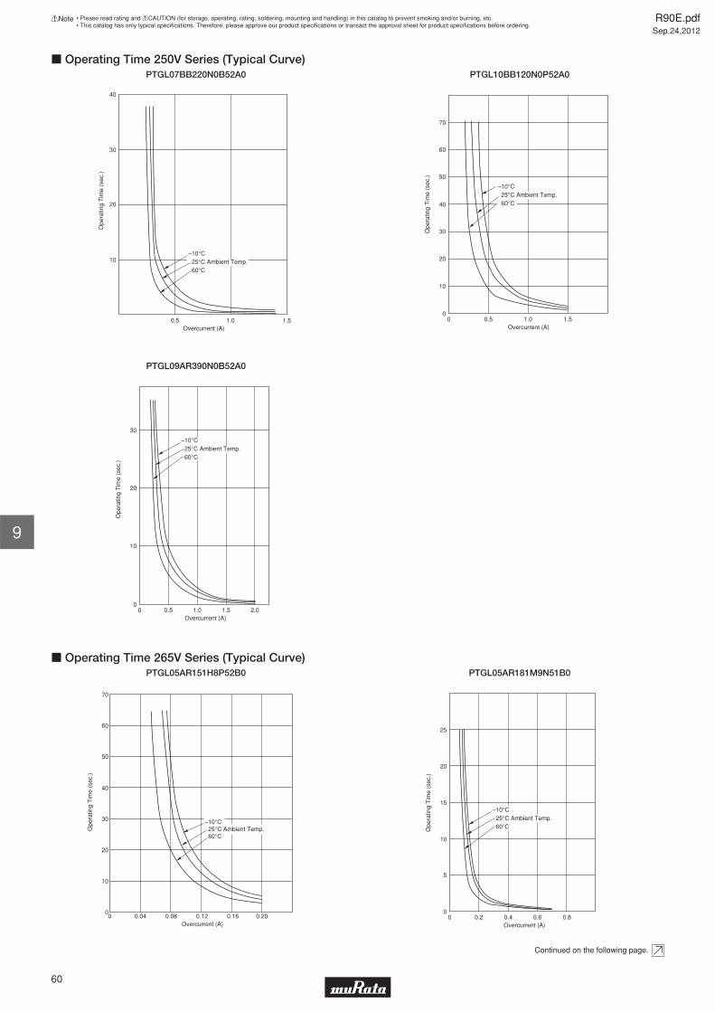
Overcurrent (A)0.5 1.0 1.5
10
20
30
40O
pera
ting
Tim
e (s
ec.)
–10°C 25°C Ambient Temp. 60°C
c Operating Time 250V Series (Typical Curve)PTGL07BB220N0B52A0
Ope
ratin
g T
ime
(sec
.)
0Overcurrent (A)
70
60
50
40
30
20
10
0
–10°C 25°C Ambient Temp. 60°C
0.5 1.0 1.5
PTGL10BB120N0P52A0
Ope
ratin
g T
ime
(sec
.)
0Overcurrent (A)
30
0
–10°C 25°C Ambient Temp. 60°C
0.5 1.0 1.5 2.0
20
10
PTGL09AR390N0B52A0
Ope
ratin
g T
ime
(sec
.)
0Overcurrent (A)
70
60
50
40
30
20
10
0
–10°C 25°C Ambient Temp. 60°C
0.04 0.08 0.12 0.16 0.20
c Operating Time 265V Series (Typical Curve)PTGL05AR151H8P52B0
Ope
ratin
g T
ime
(sec
.)
0Overcurrent (A)
25
20
15
10
5
0
–10°C 25°C Ambient Temp. 60°C
0.2 0.4 0.6 0.8
PTGL05AR181M9N51B0
Continued on the following page.
R90E.pdfSep.24,2012
60
!Note • Please read rating and !CAUTION (for storage, operating, rating, soldering, mounting and handling) in this catalog to prevent smoking and/or burning, etc.• This catalog has only typical specifi cations. Therefore, please approve our product specifi cations or transact the approval sheet for product specifi cations before ordering.
9

Continued from the preceding page.
Ope
ratin
g T
ime
(sec
.)
0Overcurrent (A)
25
20
15
10
5
0
–10°C 25°C Ambient Temp. 60°C
0.2 0.4 0.6 0.8
c Operating Time 265V Series (Typical Curve)PTGL05AR121M9N51B0
Ope
ratin
g T
ime
(sec
.)
0Overcurrent (A)
25
20
15
10
5
0
–10°C 25°C Ambient Temp. 60°C
0.5 1.0 1.5
PTGL07AR820M9A51B0
Ope
ratin
g T
ime
(sec
.)
0Overcurrent (A)
70
60
50
40
30
20
10
0
–10°C 25°C Ambient Temp. 60°C
0.2 0.4 0.6 0.8
PTGL07AR700H8B52B0
Ope
ratin
g T
ime
(sec
.)
0Overcurrent (A)
70
60
50
40
30
20
10
00.2 0.4 0.6 0.8 1.0
–10°C 25°C Ambient Temp. 60°C
PTGL07AR650H8B52B0
Ope
ratin
g T
ime
(sec
.)
0
Overcurrent (A)
70
50
40
30
20
10
00.2 0.4 0.6 0.8 1.0 1.2
60
–10°C 25°C Ambient Temp. 60°C
PTGL07AR450H8B52B0
Ope
ratin
g T
ime
(sec
.)
0Overcurrent (A)
25
20
15
10
5
0
–10°C 25°C Ambient Temp. 60°C
0.5 1.0 1.5
PTGL07AR560M9A51B0
Continued on the following page.
R90E.pdfSep.24,2012
61
!Note • Please read rating and !CAUTION (for storage, operating, rating, soldering, mounting and handling) in this catalog to prevent smoking and/or burning, etc.• This catalog has only typical specifi cations. Therefore, please approve our product specifi cations or transact the approval sheet for product specifi cations before ordering.
9
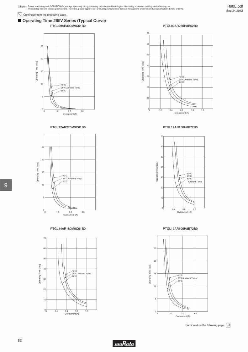
Continued from the preceding page.
Ope
ratin
g T
ime
(sec
.)
0Overcurrent (A)
25
20
15
10
5
0
–10°C 25°C Ambient Temp. 60°C
1.0 2.0 3.0
c Operating Time 265V Series (Typical Curve)PTGL09AR390M9C61B0
Ope
ratin
g T
ime
(sec
.)
0Overcurrent (A)
70
60
50
40
30
20
10
0
–10°C 25°C Ambient Temp. 60°C
0.2 0.4 0.6 0.8 1.0
PTGL09AR250H8B52B0
Ope
ratin
g T
ime
(sec
.)
0Overcurrent (A)
25
20
15
10
5
0
–10°C 25°C Ambient Temp. 60°C
1.0 2.0 3.0
PTGL12AR270M9C01B0
Ope
ratin
g T
ime
[sec
.]
0Overcurrent [A]
70
60
50
40
30
20
10
0
–10°C 25°C 60°C
Ambient Temp.
0.4 0.8 1.2
PTGL12AR150H8B72B0
Ope
ratin
g T
ime
[sec
.]
0Overcurrent [A]
70
60
50
40
30
20
10
0
–10°C 25°C Ambient Temp. 60°C
0.4 0.8 1.2 1.6
PTGL14AR180M9C01B0
Ope
ratin
g T
ime
(sec
.)
0Overcurrent (A)
25
20
15
10
5
0
–10°C 25°C Ambient Temp. 60°C
1.0 2.0 3.0
PTGL13AR100H8B72B0
Continued on the following page.
R90E.pdfSep.24,2012
62
!Note • Please read rating and !CAUTION (for storage, operating, rating, soldering, mounting and handling) in this catalog to prevent smoking and/or burning, etc.• This catalog has only typical specifi cations. Therefore, please approve our product specifi cations or transact the approval sheet for product specifi cations before ordering.
9

Continued from the preceding page.
Ope
ratin
g T
ime
[sec
.]
0Overcurrent [A]
70
60
50
40
30
20
10
0
–10°C 25°C Ambient Temp. 60°C
1.0 2.0 3.0 4.0
c Operating Time 265V Series (Typical Curve)PTGL18AR6R0H8B72B0
RL
RA
RE
RB
C
PTH
c Application Circuit(1) Transistor Protection Circuit
PowerSupply
D
C
PTH
(2) Transformer Protection Circuit 1)
PowerSupply
PTH
(3) Transformer Protection Circuit 2)
PowerSource
Fluorescent LampS S
RC
C
CHC
PTH
(4) Fluorescent Lamp Protection Circuit
Arrester
PTH
PTH
Varistor
Varistor
Telephoneor
PBX
(5) Telecommunication Circuit
R90E.pdfSep.24,2012
63
!Note • Please read rating and !CAUTION (for storage, operating, rating, soldering, mounting and handling) in this catalog to prevent smoking and/or burning, etc.• This catalog has only typical specifi cations. Therefore, please approve our product specifi cations or transact the approval sheet for product specifi cations before ordering.
9
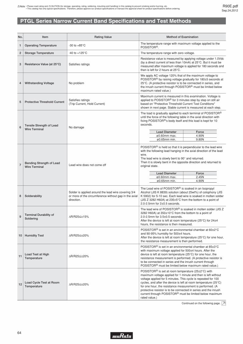
PTGL Series Narrow Current Band Specifi cations and Test Methods
Continued on the following page.
POSISTORr is set at room temperature (25±2°C) with maximum voltage applied for 1 minute and then is left without voltage applied for 5 minutes. This cycle is repeated for 100 cycles, and after the device is left at room temperature (25°C) for one hour, the resistance measurement is performed. (A protective resistor is to be connected in series and the inrush current through POSISTORr must be limited below maximum rated value.)
12Load Cycle Test at Room Temperature
ΔR/R25V±20%
POSISTORr is set in an environmental chamber at 85±3°C with maximum voltage applied for 500±4 hours. After the device is left at room temperature (25°C) for one hour, the resistance measurement is performed. (A protective resistor is to be connected in series and the inrush current through POSISTORr must be limited below maximum rated value.)
11Load Test at High Temperature
ΔR/R25V±20%
POSISTORr is set in an environmental chamber at 60±2°C and 90-95% humidity for 500±4 hours.After the device is left at room temperature (25°C) for one hour, the resistance measurement is then performed.
10 Humidity Test ΔR/R25V±20%
The lead wire of POSISTORr is soaked in molten solder (JIS Z 3282 H60A) at 350±10°C from the bottom to a point of 2.0-2.5mm for 3.5±0.5 seconds. After the device is left at room temperature (25°C) for 24±4 hours, the resistance is then measured.
9Terminal Durability of Soldering
ΔR/R25V±15%
The Lead wire of POSISTORr is soaked in an Isopropyl Alcohol (JIS K 8839) solution (about 25wt%) of colophony (JIS K 5902) for 5-10 sec. Each lead wire is soaked in molten solder (JIS Z 3282 H60A) at 235±5°C from the bottom to a point of 2.0-2.5mm for 2±0.5 seconds.
8 SolderabilitySolder is applied around the lead wire covering 3/4 or more of the circumference without gap in the axial direction.
POSISTORr is held so that it is perpendicular to the lead wire with the following lead hanging in the axial direction of the lead wire. The lead wire is slowly bent to 90° and returned.Then it is slowly bent in the opposite direction and returned to original state.7
Bending Strength of Lead Wire Terminal
Lead wire does not come off
The load is gradually applied to each terminal of POSISTORr until the force of the following table in the axial direction with fixing POSISTORr's body itself and this load is kept for 10 seconds.
6Tensile Strength of Lead Wire Terminal
No damage
Maximum current is measured in this examination. Voltage is applied to POSISTORr for 3 minutes step by step on still air based on "Protective Threshold Current Test Conditions" shown in next page. Stable current is measured at each step.
5 Protective Threshold CurrentSatisfies ratings(Trip Current, Hold Current)
We apply AC voltage 120% that of the maximum voltage to POSISTORr by raising voltage gradually for 180±5 seconds at 25°C. (A protective resistor is to be connected in series, and the inrush current through POSISTORr must be limited below maximum rated value.)
4 Withstanding Voltage No problem
Resistance value is measured by applying voltage under 1.0Vdc (by a direct current of less than 10mA) at 25°C. But it must be measured after maximum voltage is applied for 180 seconds and then is left for 2 hours at 25°C.
3 Resistance Value (at 25°C) Satisfies ratings
The temperature range with zero voltage.2 Storage Temperature -40 to +125°C
The temperature range with maximum voltage applied to thePOSISTORr.
1 Operating Temperature -30 to +85°C
Lead Diameter Force4.90N9.80N
ø0.60mm max.ø0.65mm min.
Lead Diameter Force2.45N4.90N
ø0.60mm max.ø0.65mm min.
No. Method of ExaminationRating ValueItem
R90E.pdfSep.24,2012
64
!Note • Please read rating and !CAUTION (for storage, operating, rating, soldering, mounting and handling) in this catalog to prevent smoking and/or burning, etc.• This catalog has only typical specifi cations. Therefore, please approve our product specifi cations or transact the approval sheet for product specifi cations before ordering.

PTGL Series Narrow Current Band Specifi cations and Test Methods
Continued from the preceding page.
25.0
5.0
2.5
1.0
ø0.9
25.0
25.0
25.0
2.5 2.5
3.0
(in mm)
D.C POWERSUPPLY
D.V+-
POSISTORr
1ΩDigital Voltmeter
D.V+-
Digital Voltmeter
Materials: Phenol Size: 50x50xt1.6mmLand Pattern: Cu land without through hole
1. Substrate
3. Measurement circuit
Solder POSISTORr on the substrate, then put a 150mm3 cover surrounding POSISTORr to prevent airflow.
2. Measurement condition
c Protective Threshold Current Test Conditions
R90E.pdfSep.24,2012
65
!Note • Please read rating and !CAUTION (for storage, operating, rating, soldering, mounting and handling) in this catalog to prevent smoking and/or burning, etc.• This catalog has only typical specifi cations. Therefore, please approve our product specifi cations or transact the approval sheet for product specifi cations before ordering.

PTGL Series Specifi cations and Test Methods
POSISTORr is set in an environmental chamber at 60±3°C with maximum voltage applied for 1.5 hours and then is left without voltage applied for 0.5 hours. This cycle is repeated for 1000±10 hours, and after the device is left at room temperature (25°C) for one hour, the resistance measurement is performed. (A protective resistor is to be connected in series and the inrush current through POSISTORr must be limited below max. rated value.)
Load Cycle Test at High Temperature ΔR/R25<=±20%
POSISTORr is set in an environmental chamber at 40±2°C and 90 to 95% humidity for 500±4 hours. After the device is left at room temperature (25°C) for one hour, the resistance measurement is performed.
Humidity Test ΔR/R25<=±20%
The lead wire of POSISTORr is soaked in molten solder (JIS Z 3282 H60A) at 350±10°C from the bottom to a point of 2.0 to 2.5mm for 3.5±0.5 sec. After the device is being left at room temperature (25°C) for 24±4 hours, the resistance is measured.
Terminal Durability of Soldering ΔR/R25<=±15%
The Lead wire of POSISTORr is soaked in an Isopropyl alcohol (JIS K 8839) or ethanol (JIS K 8101) solution (about 25wt%) of colophony (JIS K 5902) for 5 to 10 sec. And, each lead wire is soaked in molten solder (JIS Z 3282 H60A) at 235±5°C from the bottom to a point of 2.0 to 2.5mm for 2±0.5 sec.
SolderabilitySolder is applied around the lead wire covering 3/4 or more of the circumference without gap in the axial direction.
POSISTORr is held so that it is perpendicular to the lead wire with the following lead hanging in the axial direction of the lead wire. The lead wire is slowly bent to 90° and returned. Then it is slowly bent in the opposite direction and returned to original state.
Bending Strength of Lead Wire Terminal
Lead wire does not come off.
The load is gradually applied to each terminal of POSISTORr until the force of the following table in the axial direction with fixing POSISTORr's body itself and this load is being kept for 10 seconds.Tensile Strength of
Lead Wire Terminal No damage
We apply AC voltage 120% (16V Series: 110%) that of the maximum voltage to POSISTORr by raising voltage gradually for 180±5 seconds at 25°C. (A protective resistor is to be connected in series, and the inrush current through POSISTORr must be limited below max. rated value.)
Withstanding Voltage No problem
Resistance value is measured by applying voltage under 1.5Vdc (by a direct current of less than 10mA) at 25°C.But it must be measured after maximum voltage is applied for 180 seconds and then is left for 2 hours at 25°C.As for 16V series, measurement probes should be connected on the lead wire at the point within 2mm from the below side of the forming.Resistance should be measured by 4 wiring method.
Resistance Value (at 25°C)
Satisfies ratings
The temperature range with maximum voltage applied to the POSISTORr.
Continuous OperatingTemperature
-10 to +60 °C
Lead Diameter Force4.90N9.80N
ø0.60mm max.ø0.65mm min.
Lead Diameter Force2.45N4.90N
ø0.60mm max.ø0.65mm min.
Method of ExaminationRating ValueItem
R90E.pdfSep.24,2012
66
!Note • Please read rating and !CAUTION (for storage, operating, rating, soldering, mounting and handling) in this catalog to prevent smoking and/or burning, etc.• This catalog has only typical specifi cations. Therefore, please approve our product specifi cations or transact the approval sheet for product specifi cations before ordering.

POSISTORr for Circuit ProtectionInrush Current Suppression (Less than 100µF)
F±1.5 ød±0.05
D max. T max.
6.0
max
.4.
0±1.
5
(in mm)
Part NumberMax.
Voltage(V)
Resistance(at +25°C)
(ohm)
Max. InrushCurrent
(A)
Max. ApplyingTime of Inrush
(ms)
BodyDiameter (D)
(mm)
Thickness(T)
(mm)
LeadSpace (F)
(mm)
LeadDiameter (phi d)
(mm)
PTGL07AS121M0N51B0 280 120 ±20% 8.46 peak 10 7.8 6.0 5.0 0.5
PTGL07AS181M0N51B0 280 180 ±20% 6.22 peak 10 7.8 6.0 5.0 0.5
PTGL07AS201M0N51B0 280 200 ±20% 5.66 peak 10 7.8 6.0 5.0 0.5
Max. inrush current shows the maximum inrush current value which be introduced into "POSISTOR" at operating temperature range.
Max. applying time of inrush shows the maximum applying time of inrush current value at operating temperature range.
Operating temperature range is -40 to +105°C.
Taping type of part numbers with "A0" is available.
R90E.pdfSep.24,2012
67
!Note • Please read rating and !CAUTION (for storage, operating, rating, soldering, mounting and handling) in this catalog to prevent smoking and/or burning, etc.• This catalog has only typical specifi cations. Therefore, please approve our product specifi cations or transact the approval sheet for product specifi cations before ordering.
10
POSISTORr is one of lead type PTC Thermistor that is able to support overcurrent or inrush current issue on the power supply circuit.It is able to integrated circuit for protection from inrush current suppression with POSISTORr and relay or semiconductor switch as thyristor.
c Features1. Protection against overcurrent situations2. Automatic reset from protective trip mode3. Space-saving4. Various characteristics to meet a suitable resistance value
c ApplicationsPOSISTORr is an integrated solution to work as both current limit resistor and overcurrent fuse. It works as a stable resistor in normal operation and products itself against overcurrent situation.It can be replaced from normal resistor or the resistor with temperature fuses solution as Fig.1.
Fig.1
POSISTORr works as normal resistor in normal condition, and it works as protector against over current situation on the circuit.1. High-power switching power supply (LCD TV)2. The power supply for inverter on outside unit for Air-conditioner3. The power supply for inverter type fluorescent lamp4. Other SW type power supply
Load
POSISTORr
+-Load
+-

POSISTORr for Circuit ProtectionInrush Current Suppression for High Capacitance (100µF or more)
F±1.5 ød±0.05
D max. T max.
6.0
max
.4.
0±1.
5
(in mm)
Part NumberMax.
Voltage(V)
Resistance(at +25°C)
(ohm)
Max. InrushCurrent
(A)
Max. ChargeEnergy (at +60°C)
(J)
Max. ChargeEnergy (at +85°C)
(J)
BodyDiameter (D)
(mm)
Thickness(T)
(mm)
LeadSpace (F)
(mm)
LeadDiameter (phi d)
(mm)
PTGL14AS470H0B02BZ 280 47 ±25% 27 peak 106.9 56.9 16.0 6.5 10.0 0.6
PTGL16AS330H0B02BZ 280 33 ±25% 39 peak 130.8 80.8 18.0 6.5 10.0 0.6
PTGL16AS470H0B02BZ 280 47 ±25% 27 peak 130.8 80.8 18.0 6.5 10.0 0.6
PTGL16AS680H0B02BZ 280 68 ±25% 19 peak 130.8 80.8 18.0 6.5 10.0 0.6
PTGL16AS101H0B02BZ 280 100 ±25% 13 peak 130.8 80.8 18.0 6.5 10.0 0.6
PTGL20AS330H0D02BZ 280 33 ±25% 39 peak 181.7 131.7 22.0 6.5 10.0 0.8
PTGL20AS470H0D02BZ 280 47 ±25% 27 peak 181.7 131.7 22.0 6.5 10.0 0.8
Max. inrush current shows the maximum applying time of inrush current value at operating temperature range.
Max charge energy is defi ned as the maximum charged up energy value of over 95%.
The capacitance is calculated as the following formula.
J=CV^2/2 C: capacitance, V: peak voltage
Note: The criteria of the standard for the maximum charged up energy value of over 95%.
If there is the difference between our defi nition and yours, could you ask us free?
Operating temperature range is -20 to +85°C.
R90E.pdfSep.24,2012
68
!Note • Please read rating and !CAUTION (for storage, operating, rating, soldering, mounting and handling) in this catalog to prevent smoking and/or burning, etc.• This catalog has only typical specifi cations. Therefore, please approve our product specifi cations or transact the approval sheet for product specifi cations before ordering.
11
POSISTORr is one of lead type PTC Thermistor that is able to support overcurrent or inrush current issue on the power supply circuit.It is able to integrated circuit for protection from inrush current suppression with POSISTORr and relay or semiconductor switch as thyristor.
c Features1. Protection against overcurrent situations2. Automatic reset from protective trip mode3. Space-saving4. Various characteristics to meet a suitable resistance value
c ApplicationsPOSISTORr is an integrated solution to work as both current limit resistor and overcurrent fuse. It works as a stable resistor in normal operation and products itself against overcurrent situation.It can be replaced from normal resistor or the resistor with temperature fuses solution as Fig.1.
Fig.1
POSISTORr works as normal resistor in normal condition, and it works as protector against over current situation on the circuit.1. High-power switching power supply (LCD TV)2. The power supply for inverter on outside unit for Air-conditioner3. The power supply for inverter type fluorescent lamp4. Other SW type power supply
Load
POSISTORr
+-Load
+-

Inrush Current Suppression Specifi cations and Test Methods
POSISTORr is set in a room temperature (25±2°C) with maximum voltage applied for 1 minute, and then is left without voltage applied for 5 minutes. This cycle is repeated for 10k cycles, and after the device is left at room temperature (25°C) for one hour, the resistance measurement is performed.
Load Cycle Test at Room Temperature ΔR/R25V±20%
POSISTORr is set in an environmental chamber at 85±3°C with maximum voltage applied for 500±4 hours. After the device is left at room temperature (25°C) for one hour, the resistance measurement is performed.
High TemperatureContinuous Load ΔR/R25V±20%
POSISTORr is set in an environmental chamber at 85±3°C and 85% humidity for 500±4 hours.After the device is left at room temperature (25°C) for one hour, the resistance measurement is performed.
Humidity Test ΔR/R25V±20%
Method of ExaminationRating ValueItem
R90E.pdfSep.24,2012
69
!Note • Please read rating and !CAUTION (for storage, operating, rating, soldering, mounting and handling) in this catalog to prevent smoking and/or burning, etc.• This catalog has only typical specifi cations. Therefore, please approve our product specifi cations or transact the approval sheet for product specifi cations before ordering.

POSISTORr for Circuit ProtectionOverheat Sensing Chip Tight Tolerance Type
This chip PTC Thermistor is a refl ow soldering SMD type for overheat sensing for power transistors, power diodes and power ICs in hybrid circuits.
c Features1. SMD type is helpful for miniaturizing circuits because of its small size and light weight.2. Excellent thermal response due to small size3. Solid-state construction provides excellent resistance to mechanical vibration and impact resistance.4. Contactless operation provides noiseless operation.
L
T
Part NumberL W T
Dimensions (mm)e g
1.0±0.051.6±0.15
0.5±0.050.8±0.15
0.5±0.050.8±0.15
0.15 to 0.40.1 to 0.6
0.3 min.-
PRF15_RCPRF18_RB
W
e eg
Chip Tight Tolerance Type 0402 (1005) Size
Part NumberSensing Temperature
(at 10k ohm)(°C)
Sensing Temperature(at 100k ohm)
(°C)
MaximumVoltage
(V)
Resistance(at 25°C)(k ohm)
OperatingTemperature Range
(°C)
PRF15AR102RB6RC 135 ±5°C 150 ±3°C 32 1 ±50% -40 to 160
PRF15BA102RB6RC 125 ±5°C 140 ±3°C 32 1 ±50% -40 to 150
PRF15BB102RB6RC 115 ±5°C 130 ±3°C 32 1 ±50% -40 to 140
PRF15BC102RB6RC 105 ±5°C 120 ±3°C 32 1 ±50% -40 to 130
PRF15BD102RB6RC 95 ±5°C 110 ±3°C 32 1 ±50% -40 to 120
PRF15BE102RB6RC 85 ±5°C 100 ±3°C 32 1 ±50% -40 to 110
PRF15BF102RB6RC 75 ±5°C 90 ±3°C 32 1 ±50% -40 to 100
PRF15BG102RB6RC 65 ±5°C 80 ±3°C 32 1 ±50% -40 to 90
This series is applied to refl ow soldering.
Part NumberSensing Temperature
(at 4.7M ohm)(°C)
MaximumVoltage
(V)
Resistance(at 25°C)(k ohm)
OperatingTemperature Range
(°C)
PRF15BB103RB6RC 130 ±3°C 32 10 ±50% -20 to 140
PRF15BE103RB6RC 100 ±3°C 32 10 ±50% -20 to 110
PRF15BG103RB6RC 80 ±3°C 32 10 ±50% -20 to 90
This series is applied to refl ow soldering.
Chip Tight Tolerance Type 0603 (1608) Size
This series is applied to fl ow/refl ow soldering.
This series is recognized by UL.
Part NumberSensing Temperature
(at 4.7k ohm)(°C)
Sensing Temperature(at 47k ohm)
(°C)
MaximumVoltage
(V)
Resistance(at 25°C)
(ohm)
OperatingTemperature Range
(°C)
PRF18BB471RB5RB 115 ±3°C 130 ±7°C 32 470 ±50% -20 to 140
PRF18BC471RB5RB 105 ±3°C 120 ±7°C 32 470 ±50% -20 to 130
PRF18BD471RB5RB 95 ±3°C 110 ±7°C 32 470 ±50% -20 to 120
PRF18BE471RB5RB 85 ±3°C 100 ±7°C 32 470 ±50% -20 to 110
PRF18BF471RB5RB 75 ±3°C 90 ±7°C 32 470 ±50% -20 to 100
PRF18BG471RB5RB 65 ±3°C 80 ±7°C 32 470 ±50% -20 to 90
R90E.pdfSep.24,2012
70
!Note • Please read rating and !CAUTION (for storage, operating, rating, soldering, mounting and handling) in this catalog to prevent smoking and/or burning, etc.• This catalog has only typical specifi cations. Therefore, please approve our product specifi cations or transact the approval sheet for product specifi cations before ordering.
12

POSISTORr for Circuit ProtectionOverheat Sensing Chip Type
This chip PTC Thermistor is a refl ow soldering SMD type for overheat sensing for power transistors, power diodes and power ICs in hybrid circuits.
c Features1. SMD type is helpful for miniaturizing circuits because of its small size and light weight.2. Excellent thermal response due to small size3. Solid-state construction provides excellent resistance to mechanical vibration and impact resistance.4. Contactless operation provides noiseless operation.
L
T
Part NumberL W T
Dimensions (mm)e g
1.6±0.152.0±0.2
0.8±0.151.25±0.2
0.8±0.150.9±0.2
0.1 to 0.60.2 min.
-0.5 min.
PRF18_RBPRF21_RA
W
e eg
Chip Type 0603 (1608) Size
Part NumberSensing Temperature
(at 4.7k ohm)(°C)
Sensing Temperature(at 47k ohm)
(°C)
MaximumVoltage
(V)
Resistance(at 25°C)
(ohm)
OperatingTemperature Range
(°C)
PRF18AS471QB5RB 145 ±5°C - 32 470 ±50% -20 to 160
PRF18AR471QB5RB 135 ±5°C 150 ±7°C 32 470 ±50% -20 to 160
PRF18BA471QB5RB 125 ±5°C 140 ±7°C 32 470 ±50% -20 to 150
PRF18BB471QB5RB 115 ±5°C 130 ±7°C 32 470 ±50% -20 to 140
PRF18BC471QB5RB 105 ±5°C 120 ±7°C 32 470 ±50% -20 to 130
PRF18BD471QB5RB 95 ±5°C 110 ±7°C 32 470 ±50% -20 to 120
PRF18BE471QB5RB 85 ±5°C 100 ±7°C 32 470 ±50% -20 to 110
PRF18BF471QB5RB 75 ±5°C 90 ±7°C 32 470 ±50% -20 to 100
PRF18BG471QB5RB 65 ±5°C 80 ±7°C 32 470 ±50% -20 to 90
This series is applied to fl ow/refl ow soldering.
This series is recognized by UL.
Chip Type 0805 (2012) Size
Part NumberSensing Temperature
(at 4.7k ohm)(°C)
MaximumVoltage
(V)
Resistance(at 25°C)
(ohm)
OperatingTemperature Range
(°C)
PRF21AS471QB5RA 145 ±5°C 32 470 ±50% -20 to 160
PRF21AR471QB5RA 135 ±5°C 32 470 ±50% -20 to 150
PRF21BA471QB5RA 125 ±5°C 32 470 ±50% -20 to 140
PRF21BB471QB5RA 115 ±5°C 32 470 ±50% -20 to 130
PRF21BC471QB5RA 105 ±5°C 32 470 ±50% -20 to 120
PRF21BD471QB5RA 95 ±5°C 32 470 ±50% -20 to 110
PRF21BE471QB5RA 85 ±5°C 32 470 ±50% -20 to 100
This series is applied to fl ow/refl ow soldering.
This series is recognized by UL.
R90E.pdfSep.24,2012
71
!Note • Please read rating and !CAUTION (for storage, operating, rating, soldering, mounting and handling) in this catalog to prevent smoking and/or burning, etc.• This catalog has only typical specifi cations. Therefore, please approve our product specifi cations or transact the approval sheet for product specifi cations before ordering.
13
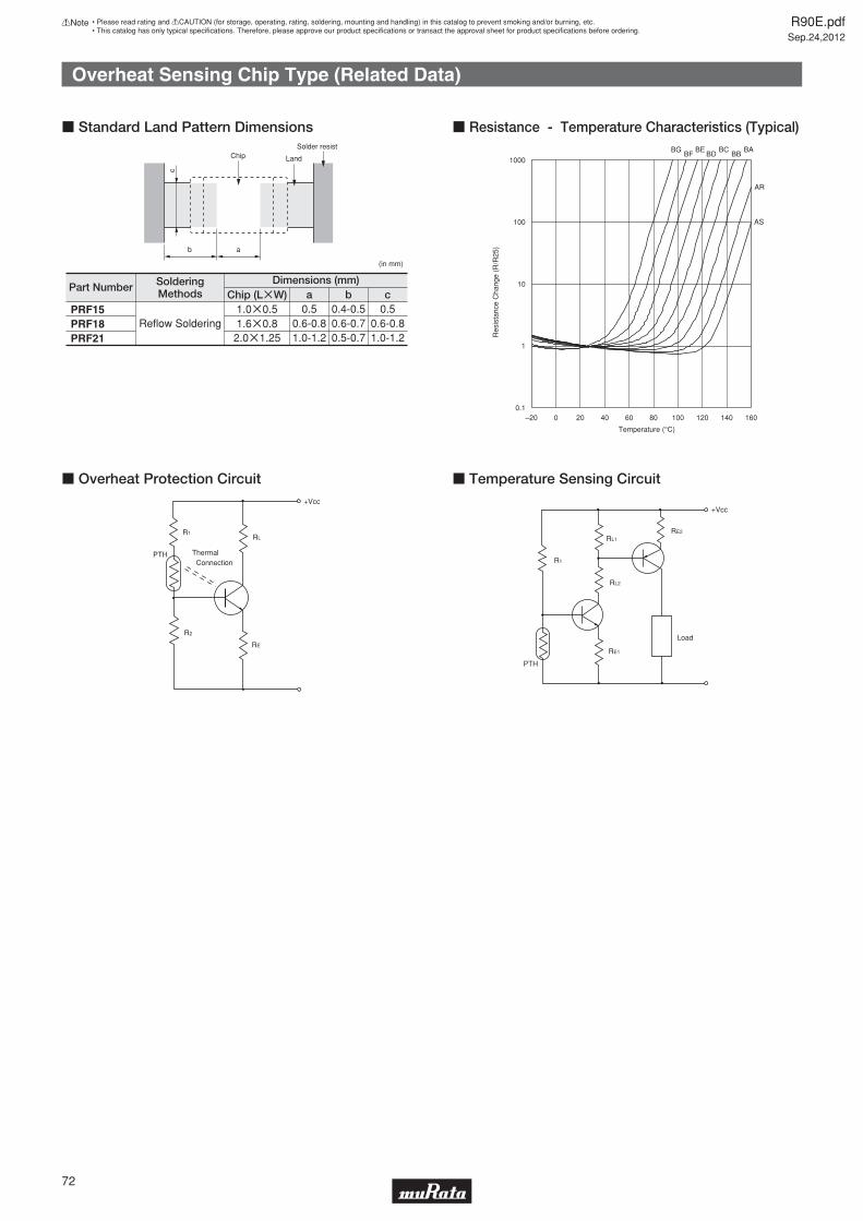
Overheat Sensing Chip Type (Related Data)
a
c
Solder resist
(in mm)
b
LandChip
Part NumberChip (LgW) a
Dimensions (mm)b c
1.0g0.51.6g0.8
SolderingMethods
0.5 0.4-0.5 0.5Reflow Soldering 0.6-0.8 0.6-0.7 0.6-0.8
2.0g1.25 1.0-1.2 0.5-0.7 1.0-1.2
PRF15PRF18PRF21
c Standard Land Pattern Dimensions
0.1
1
10
100
1000
–20 0 20 40 60 80 100 120 140 160
Temperature (°C)
BEBD
BCBB
BA
AR
AS
BFBG
Res
ista
nce
Cha
nge
(R/R
25)
R1
R2
Thermal
+Vcc
RL
RE
ConnectionPTH
c Overheat Protection Circuit
R1
RL1
RL2
RE1
RE2
Load
+Vcc
PTH
c Temperature Sensing Circuit
R90E.pdfSep.24,2012
72
!Note • Please read rating and !CAUTION (for storage, operating, rating, soldering, mounting and handling) in this catalog to prevent smoking and/or burning, etc.• This catalog has only typical specifi cations. Therefore, please approve our product specifi cations or transact the approval sheet for product specifi cations before ordering.
c Resistance - Temperature Characteristics (Typical)
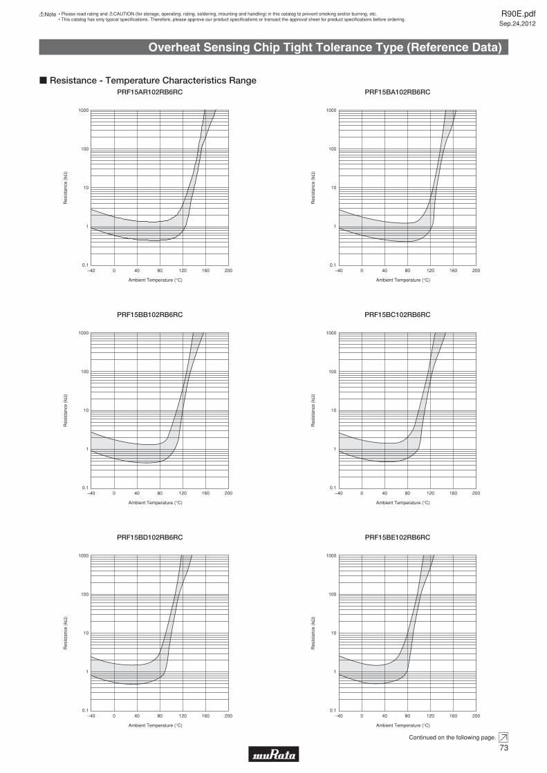
Overheat Sensing Chip Tight Tolerance Type (Reference Data)
Ambient Temperature (°C)
Res
ista
nce
(kΩ
)
0.1
1
10
100
1000
–40 0 40 80 120 160 200
c Resistance - Temperature Characteristics RangePRF15AR102RB6RC
Ambient Temperature (°C)
Res
ista
nce
(kΩ
)
0.1
1
10
100
1000
–40 0 40 80 120 160 200
PRF15BA102RB6RC
Ambient Temperature (°C)
Res
ista
nce
(kΩ
)
0.1
1
10
100
1000
–40 0 40 80 120 160 200
PRF15BB102RB6RC
Ambient Temperature (°C)
Res
ista
nce
(kΩ
)
0.1
1
10
100
1000
–40 0 40 80 120 160 200
PRF15BC102RB6RC
Continued on the following page.
R90E.pdfSep.24,2012
73
!Note • Please read rating and !CAUTION (for storage, operating, rating, soldering, mounting and handling) in this catalog to prevent smoking and/or burning, etc.• This catalog has only typical specifi cations. Therefore, please approve our product specifi cations or transact the approval sheet for product specifi cations before ordering.
Ambient Temperature (°C)
Res
ista
nce
(kΩ
)
0.1
1
10
100
1000
–40 0 40 80 120 160 200
PRF15BD102RB6RC
Ambient Temperature (°C)
Res
ista
nce
(kΩ
)
0.1
1
10
100
1000
–40 0 40 80 120 160 200
PRF15BE102RB6RC

Overheat Sensing Chip Tight Tolerance Type (Reference Data)
Continued from the preceding page.
c Resistance - Temperature Characteristics Range
Ambient Temperature (°C)
Res
ista
nce
(kΩ
)
0.1
1
10
100
1000
–40 0 40 80 120 160 200
PRF15BF102RB6RC
Ambient Temperature (°C)
Res
ista
nce
(kΩ
)
0.1
1
10
100
1000
–40 0 40 80 120 160 200
PRF15BG102RB6RC
Continued on the following page.
R90E.pdfSep.24,2012
74
!Note • Please read rating and !CAUTION (for storage, operating, rating, soldering, mounting and handling) in this catalog to prevent smoking and/or burning, etc.• This catalog has only typical specifi cations. Therefore, please approve our product specifi cations or transact the approval sheet for product specifi cations before ordering.
Ambient Temperature (°C)
Res
ista
nce
(kΩ
)
-20 0 20 40 60 80 100 120 140 160
100000
10000
1000
100
10
1
PRF15BB103RB6RC
Ambient Temperature (°C)
Res
ista
nce
(kΩ
)
1
10
100
1000
10000
100000
–20 0 20 40 60 80 100 120 140
PRF15BE103RB6RC
Ambient Temperature (°C)
Res
ista
nce
(kΩ
)
1
10
100
1000
10000
100000
–20 0 20 40 60 80 100 120 140
PRF15BG103RB6RC
Temperature (°C)
Res
ista
nce
(Ω)
–20 0 20 40 60 80 100 120 140 160100
100000
10000
1000
PRF18BB471RB5RB

Overheat Sensing Chip Tight Tolerance Type (Reference Data)
Continued from the preceding page.
Temperature (°C)
Res
ista
nce
(Ω)
–20 0 20 40 60 80 100 120 140 160100
100000
10000
1000
c Resistance - Temperature Characteristics RangePRF18BC471RB5RB
Temperature (°C)
Res
ista
nce
(Ω)
–20 0 20 40 60 80 100 120 140 160100
100000
10000
1000
PRF18BD471RB5RB
Temperature (°C)
Res
ista
nce
(Ω)
–20 0 20 40 60 80 100 120 140 160100
100000
10000
1000
PRF18BE471RB5RB
Temperature (°C)
Res
ista
nce
(Ω)
–20 0 20 40 60 80 100 120 140 160100
100000
10000
1000
PRF18BF471RB5RB
R90E.pdfSep.24,2012
75
!Note • Please read rating and !CAUTION (for storage, operating, rating, soldering, mounting and handling) in this catalog to prevent smoking and/or burning, etc.• This catalog has only typical specifi cations. Therefore, please approve our product specifi cations or transact the approval sheet for product specifi cations before ordering.
Temperature (°C)
Res
ista
nce
(Ω)
–20 0 20 40 60 80 100 120 140 160100
100000
10000
1000
PRF18BG471RB5RB

Overheat Sensing Chip Type (Ref. Only)
Temperature (°C)
Res
ista
nce
(Ω)
–20 0 20 40 60 80 100 120 140 160100
100000
10000
1000
c Resistance - Temperature Characteristics RangePRF18/21AS471Q Type
Temperature (°C)
Res
ista
nce
(Ω)
–20 0 20 40 60 80 100 120 140 160100
100000
10000
1000
PRF18/21AR471Q Type
Temperature (°C)
Res
ista
nce
(Ω)
–20 0 20 40 60 80 100 120 140 160100
100000
10000
1000
PRF18/21BA471Q Type
Temperature (°C)
Res
ista
nce
(Ω)
–20 0 20 40 60 80 100 120 140 160100
100000
10000
1000
PRF18/21BB471Q Type
Continued on the following page.
R90E.pdfSep.24,2012
76
!Note • Please read rating and !CAUTION (for storage, operating, rating, soldering, mounting and handling) in this catalog to prevent smoking and/or burning, etc.• This catalog has only typical specifi cations. Therefore, please approve our product specifi cations or transact the approval sheet for product specifi cations before ordering.
Temperature (°C)
Res
ista
nce
(Ω)
–20 0 20 40 60 80 100 120 140 160100
100000
10000
1000
PRF18/21BC471Q Type
Temperature (°C)
Res
ista
nce
(Ω)
–20 0 20 40 60 80 100 120 140 160100
100000
10000
1000
PRF18/21BD471Q Type

Overheat Sensing Chip Type (Ref. Only)
Continued from the preceding page.
c Resistance - Temperature Characteristics Range
Temperature (°C)
Res
ista
nce
(Ω)
–20 0 20 40 60 80 100 120 140 160100
100000
10000
1000
PRF18/21BE471Q Type
Temperature (°C)
Res
ista
nce
(Ω)
–20 0 20 40 60 80 100 120 140 160100
100000
10000
1000
PRF18BF471Q Type
R90E.pdfSep.24,2012
77
!Note • Please read rating and !CAUTION (for storage, operating, rating, soldering, mounting and handling) in this catalog to prevent smoking and/or burning, etc.• This catalog has only typical specifi cations. Therefore, please approve our product specifi cations or transact the approval sheet for product specifi cations before ordering.
Temperature (°C)
Res
ista
nce
(Ω)
–20 0 20 40 60 80 100 120 140 160100
100000
10000
1000
PRF18BG471Q Type

Overheat Sensing Chip Tight Tolerance Type Specifi cations and Test Methods
Reference standard: IEC 60068-2-2 (2007)· Soldered PTC to PCB (**)· (Max. operating temp.)±2°C· Applied max. voltage· 1000+48/-0 hrs.
9 High Temperature Load
Reference standard: IEC 60068-2-14 (2009)[ Test Na ]· Soldered PTC to PCB (**)· Transport time: <10 sec.· Test condition: See below table
· Test cycle: 5 cycles
8 Thermal Shock
Reference standard: IEC 60068-2-67 (1995)· Soldered PTC to PCB (**)· +85±2°C, 85±5%RH· 1000+48/-0 hrs
7 Damp Heat, Steady State
Reference standard: IEC 60068-2-1 (2007)· Soldered PTC to PCB (**)· (Min. operating temp.)±3°C· 1000+48/-0 hrs
6 Low Temperature Storage
Reference standard: IEC 60068-2-2 (2007)· Soldered PTC to PCB (**)· (Max. operating temp.)±2°C· 1000+48/-0 hrs.
5 High Temperature Storage
· Appearance: No defects or abnormalities· Resistance (R25) change: Less than ±20% (*)
Reference standard: IEC 60068-2-58 (2004)[ Solder bath method ]· Solder: Sn-3.0Ag-0.5Cu· Preheat: 150±5°C, 90 to 120s· Solder temp.: 260±5°C· Immersion time: 10±1s
4 Resistance to Soldering Heat · Appearance: No defects or abnormalities· Resistance (R25) change: Less than ±20% (*)
Reference standard: IEC 60068-2-58 (2004)· Solder: Sn-3.0Ag-0.5Cu· Solder temp.: 245±5°C· Immersion time: 3±0.3s
3 Solderability Wetting of soldering area: U95%
Reference standard: IEC 60068-2-6 (1995)· Soldered PTC to PCB (**)· Frequency range: 10 to 55Hz· Amplitude: 1.5mm· Sweep rate: 1 octave/min.· Direction: X-Y-Z (3 direction)· 24 cycles in each axis
2 Vibration±20% (*)
After applying maximum operating voltage for 3 mins. and leaving for 2 hours in 25°C, measured by applying voltage less than DC1.0V.
1 Resistance Value at 25°C Within the specified range
*: The resistance value after the test. It is measured by applying voltage less than DC1.0V after left at 25±2°C for 2hrs. **: Above mentioned soldering is done under the following conditions at our side. · Glass-Epoxy PC board · Standard land dimension · Standard solder paste · Standard solder profile Above conditions are mentioned in Notice.
No. Test ConditionsCreteriaItem
ConditionStep(Min. Operating temp.)±3°C(Max. Operating temp.)±2°C
Time30min.30min.
12
c PRF15_102R Series
R90E.pdfSep.24,2012
78
!Note • Please read rating and !CAUTION (for storage, operating, rating, soldering, mounting and handling) in this catalog to prevent smoking and/or burning, etc.• This catalog has only typical specifi cations. Therefore, please approve our product specifi cations or transact the approval sheet for product specifi cations before ordering.

Overheat Sensing Chip Tight Tolerance Type Specifi cations and Test Methods
· Soldered PTC to PCB. (**)· 85±3°C (in air), load max. operating voltage for 1000+12/-0 hrs.
9 High Temperature Load
· Soldered PTC to PCB. (**)· Cycles: 5 cycles· Conditions: See below table
8 Temperature Cycling
· Soldered PTC to PCB. (**)· +60±3°C, 90 to 95%RH leave for 1000+12/-0 hrs.
7 Damp Heat
· Soldered PTC to PCB. (**)· -20±3°C leave for 1000+12/-0 hrs.
6 Cold
· Soldered PTC to PCB. (**)· +125±3°C leave for 1000+12/-0 hrs.This test condition is according to "JIS C 60068-2-2 (1995)."
5 Dry Heat
There is no abnormal appearance after the test.Resistance change is less than ±20%.(*)
· Solder temp.: 260±5°C· Solder: Sn 63%/Pb 37% (or 60/40%)· Flux: Containing less than 0.2wt% of chlorine.· Soaking time: 10±1 secs.· Soaking position: Until a whole electrode is soaked.· Preheating: 150±5°C 3 mins.This test condition is according to "JIS C 60068-2-58 (2006)."
4 Soldering Heat ResistanceThere is no abnormal appearance after the test.Resistance change is less than ±20%.(*)
· Solder temp.: 230±5°C· Solder: Sn 63%/Pb 37% (or 60/40%)· Soaking time: 3±0.5 secs. · Soaking position: Until a whole electrode is soaked.This test condition is according to "JIS C 60068-2-58 (2006)."
3 SolderabilityMin. 95% electrode is covered with new solder.Resistance change is less than ±20%.(*)
Soldered PTC to PCB (**)· Vibration: 10 to 55 to 10Hz (1min.)· Max. Amplitude: 1.5mmVibrate for 2 hours in each of 3 mutually perpendicular plane for a total of 6 hours.This test condition is according to "JIS C 60068-2-6 (1999)."
2 VibrationThere is no abnormal appearance after the test.Resistance change is less than ±20%.(*)
After applying maximum operating voltage for 3 minutes and leaving for 2 hours at 25°C, measured by applying voltage of less than 3VDC.
1 Resistance Value (at 25°C) The resistance value should be within the specified tolerance.
*: The resistance measurement after the test. It is measured by applying voltage less than 3VDC after left at 25±2°C for 2 hours.**: Above mentioned soldering is done under the following conditions at our side. · Glass-Epoxy PC board · Standard land dimension · Standard solder paste · Standard solder profile Above conditions are mentioned in Notice.
No. Method of ExaminationRating valueItem
Temp. (°C)Step-20+0, -3
Room temp.+125+3, -0
Room temp.
Time (minute)30
10 to 1530
10 to 15
1234
c PRF15_103R Series
R90E.pdfSep.24,2012
79
!Note • Please read rating and !CAUTION (for storage, operating, rating, soldering, mounting and handling) in this catalog to prevent smoking and/or burning, etc.• This catalog has only typical specifi cations. Therefore, please approve our product specifi cations or transact the approval sheet for product specifi cations before ordering.
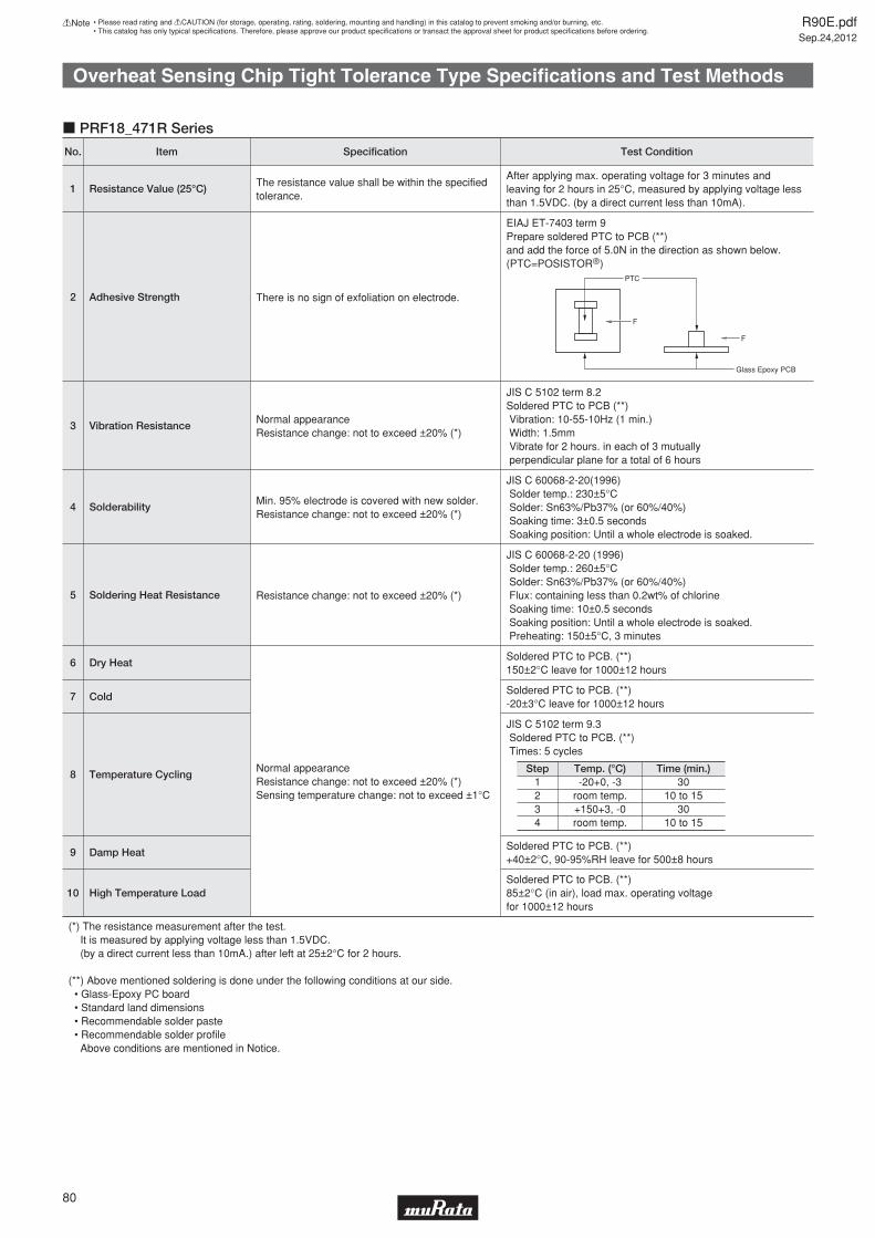
Overheat Sensing Chip Tight Tolerance Type Specifi cations and Test Methods
Soldered PTC to PCB. (**)85±2°C (in air), load max. operating voltagefor 1000±12 hours
10 High Temperature Load
Soldered PTC to PCB. (**)+40±2°C, 90-95%RH leave for 500±8 hours
9 Damp Heat
JIS C 5102 term 9.3 Soldered PTC to PCB. (**) Times: 5 cycles
8 Temperature Cycling
Soldered PTC to PCB. (**)-20±3°C leave for 1000±12 hours
7 Cold
Soldered PTC to PCB. (**)150±2°C leave for 1000±12 hours
6 Dry Heat
Normal appearanceResistance change: not to exceed ±20% (*)Sensing temperature change: not to exceed ±1°C
JIS C 60068-2-20 (1996) Solder temp.: 260±5°C Solder: Sn63%/Pb37% (or 60%/40%) Flux: containing less than 0.2wt% of chlorine Soaking time: 10±0.5 seconds Soaking position: Until a whole electrode is soaked. Preheating: 150±5°C, 3 minutes
5 Soldering Heat Resistance Resistance change: not to exceed ±20% (*)
JIS C 60068-2-20(1996) Solder temp.: 230±5°C Solder: Sn63%/Pb37% (or 60%/40%) Soaking time: 3±0.5 seconds Soaking position: Until a whole electrode is soaked.
4 SolderabilityMin. 95% electrode is covered with new solder.Resistance change: not to exceed ±20% (*)
JIS C 5102 term 8.2Soldered PTC to PCB (**) Vibration: 10-55-10Hz (1 min.) Width: 1.5mm Vibrate for 2 hours. in each of 3 mutually perpendicular plane for a total of 6 hours
3 Vibration ResistanceNormal appearanceResistance change: not to exceed ±20% (*)
EIAJ ET-7403 term 9Prepare soldered PTC to PCB (**)and add the force of 5.0N in the direction as shown below. (PTC=POSISTORr)
2 Adhesive Strength There is no sign of exfoliation on electrode.
After applying max. operating voltage for 3 minutes and leaving for 2 hours in 25°C, measured by applying voltage less than 1.5VDC. (by a direct current less than 10mA).
1 Resistance Value (25°C)The resistance value shall be within the specified tolerance.
(*) The resistance measurement after the test. It is measured by applying voltage less than 1.5VDC. (by a direct current less than 10mA.) after left at 25±2°C for 2 hours.
(**) Above mentioned soldering is done under the following conditions at our side.
Above conditions are mentioned in Notice.
No. Test ConditionSpecificationItem
Temp. (°C)Step-20+0, -3
room temp.+150+3, -0room temp.
Time (min.)30
10 to 1530
10 to 15
1234
F
F
PTC
c PRF18_471R Series
R90E.pdfSep.24,2012
80
!Note • Please read rating and !CAUTION (for storage, operating, rating, soldering, mounting and handling) in this catalog to prevent smoking and/or burning, etc.• This catalog has only typical specifi cations. Therefore, please approve our product specifi cations or transact the approval sheet for product specifi cations before ordering.

Overheat Sensing Chip Type Specifi cations and Test Methods
Soldered PTC to PCB. (**)85±2°C (in air), load max. operating voltagefor 1000±12 hours
10 High Temperature Load
Soldered PTC to PCB. (**)+40±2°C, 90-95%RH leave for 500±8 hours
9 Damp Heat
JIS C 5102 term 9.3 Soldered PTC to PCB. (**) Times: 5 cycles
8 Temperature Cycling
Soldered PTC to PCB. (**)-20±3°C leave for 1000±12 hours
7 Cold
Soldered PTC to PCB. (**)150±2°C leave for 1000±12 hours
6 Dry Heat
Normal appearanceResistance change: not to exceed ±20% (*)
JIS C 60068-2-20 (1996) Solder temp.: 260±5°C Solder: Sn63%/Pb37% (or 60%/40%) Flux: containing less than 0.2wt% of chlorine Soaking time: 10±0.5 seconds Soaking position: Until a whole electrode is soaked. Preheating: 150±5°C, 3 minutes
5 Soldering Heat Resistance Resistance change: not to exceed ±20% (*)
JIS C 60068-2-20(1996) Solder temp.: 230±5°C Solder: Sn63%/Pb37% (or 60%/40%) Soaking time: 3±0.5 seconds Soaking position: Until a whole electrode is soaked.
4 SolderabilityMin. 95% electrode is covered with new solder.Resistance change: not to exceed ±20% (*)
JIS C 5102 term 8.2Soldered PTC to PCB (**) Vibration: 10-55-10Hz (1 min.) Width: 1.5mm Vibrate for 2 hours. in each of 3 mutually perpendicular plane for a total of 6 hours
3 Vibration ResistanceNormal appearanceResistance change: not to exceed ±20% (*)
EIAJ ET-7403 term 9Prepare soldered PTC to PCB (**)and add the force of 5.0N in the direction as shown below. (PTC=POSISTORr)
2 Adhesive Strength There is no sign of exfoliation on electrode.
After applying max. operating voltage for 3 minutes and leaving for 2 hours in 25°C, measured by applying voltage less than 1.5VDC. (by a direct current less than 10mA).
1 Resistance Value (25°C)The resistance value shall be within the specified tolerance.
(*) The resistance measurement after the test. It is measured by applying voltage less than 1.5VDC. (by a direct current less than 10mA.) after left at 25±2°C for 2 hours.
(**) Above mentioned soldering is done under the following conditions at our side.
Above conditions are mentioned in Notice.
No. Test ConditionSpecificationItem
Temp. (°C)Step-20+0, -3
room temp.+150+3, -0room temp.
Time (min.)30
10 to 1530
10 to 15
1234
F
F
PTC
c PRF18/21_471Q Series
R90E.pdfSep.24,2012
81
!Note • Please read rating and !CAUTION (for storage, operating, rating, soldering, mounting and handling) in this catalog to prevent smoking and/or burning, etc.• This catalog has only typical specifi cations. Therefore, please approve our product specifi cations or transact the approval sheet for product specifi cations before ordering.

POSISTORr for Circuit ProtectionOverheat Sensing Lead Type
PTFM Series has been developed for protecting powertransistors, stereo main amplifi ers, etc. from overheating, and also for sensing the temperature of other components which may be overheated. The "POSISTOR" offers an excellent temperature sensing ability, exhibiting a steep change in electrical resistivity near the temperature setting. PTFL Series is suitable for use as an air temperature sensor.
c Features1. PTFM Series is a screw-fi xing type and PTFL Series is a lead type, providing ease of mounting.2. Compact and light design as well as excellent thermal response.3. Solid-state construction withstands mechanical vibration and impact suffi ciently.4. Contactless operation provides a prolonged service life, yet permits noiseless operation.5. The operating point of "POSISTOR" is set on the steepest point along the resistance-temperature characteristic curve, thus performing the overheat protective operation securely.6. PTFM Series and PTFL Series have the same temperature characteristic, providing a selection depending on the mounting method.
3.5±1.5
4.0 max.
ø0.5±0.05
(in mm)
5.0 max.
3.0
max
.
25 m
in.
PTFL Series
ø0.5±0.05
2.5m
ax.
t0.5±0.05
3.0±0.37.5±0.4
3.7±0.3
13.2
±0.
539
±5
3.5±1.5
in mm
PTFM Series
Part NumberMax. Voltage
(V)Sensing Temp. (TS)
(°C)
Resistance Valueat 25°C (max.)
(ohm)
Resistance Value (TS-10°C) (max.)
(ohm)
Resistance Value (TS°C) (min.)
(ohm)
PTFp4BH471Q2N34B0 16 60 100 330 470
PTFp4BG471Q2N34B0 16 70 100 330 470
PTFp4BF471Q2N34B0 16 80 100 330 470
PTFp4BE471Q2N34B0 16 90 100 330 470
PTFp4BD471Q2N34B0 16 100 100 330 470
PTFp4BC471Q2N34B0 16 110 100 330 470
PTFp4BB471Q2N34B0 16 120 100 330 470
PTFp4BH222Q2N34B0 16 60 330 1.5k 2.2k
PTFp4BG222Q2N34B0 16 70 330 1.5k 2.2k
PTFp4BF222Q2N34B0 16 80 330 1.5k 2.2k
PTFp4BE222Q2N34B0 16 90 330 1.5k 2.2k
PTFp4BD222Q2N34B0 16 100 330 1.5k 2.2k
PTFp4BC222Q2N34B0 16 110 330 1.5k 2.2k
PTFp4BB222Q2N34B0 16 120 330 1.5k 2.2k
A blank is fi lled with type codes. (L: Lead type, M: with Lug-terminal)
Operating temperature range is -10 to TS+10°C.
Please contact us for UL recognized products.
R90E.pdfSep.24,2012
82
!Note • Please read rating and !CAUTION (for storage, operating, rating, soldering, mounting and handling) in this catalog to prevent smoking and/or burning, etc.• This catalog has only typical specifi cations. Therefore, please approve our product specifi cations or transact the approval sheet for product specifi cations before ordering.
14

Res
ista
nce
Cha
nge
(R/R
25°C
)
–20Temperature (°C)
104
103
102
10
1
0 20 40 60 80 100 120 140
BC
BD
BE
BF
BG
BH
BB
c Resistance - Temperature Characteristics
6050403020100
20
0
40
60
80
100
Time (sec.)
Aluminum plateT=90°C constant
PTFM04BE222Q2N34B0
Relation between resistance change and time after POSISTORr PTFM04BE222Q2N34B0 is installed on the part heated at a constant temperature of 90°C (3mm thick alminum sheet) is shown in the figure above.
Res
ista
nce
Cha
nge
(%)
(R
/R90
°C)
Heater
R meterPOSISTORr
Screw
c Example of Thermal Response TimeOperating Time of POSISTORr
R1
R2
Thermal
+Vcc
RL
RE
ConnectionPTH
c Overheat Protection Circuit
R1
RL1
RL2
RE1
RE2
Load
+Vcc
PTH
c Overheat Sensing Circuit
Res
ista
nce
(Ω)
0
Temperature (°C)
102
–20 40 60 12080 100 140
10
103
104
20
c Resistance - Temperature Characteristics Range (Ref. Only)PTF_04BH471Q2N34B0
Res
ista
nce
(Ω)
0
Temperature (°C)
102
–20 40 60 12080 100 140
10
103
104
20
PTF_04BG471Q2N34B0
Continued on the following page.
R90E.pdfSep.24,2012
83
!Note • Please read rating and !CAUTION (for storage, operating, rating, soldering, mounting and handling) in this catalog to prevent smoking and/or burning, etc.• This catalog has only typical specifi cations. Therefore, please approve our product specifi cations or transact the approval sheet for product specifi cations before ordering.
14

Continued from the preceding page.
Res
ista
nce
(Ω)
0
Temperature (°C)
102
–20 40 60 12080 100 140
10
103
104
20
c Resistance - Temperature Characteristics Range (Ref. Only)PTF_04BF471Q2N34B0
Res
ista
nce
(Ω)
0
Temperature (°C)
102
–20 40 60 12080 100 140
10
103
104
20
PTF_04BE471Q2N34B0
Res
ista
nce
(Ω)
–20
Temperature (°C)
102
0 20 40 10060 80 140120
10
103
104
PTF_04BD471Q2N34B0
Res
ista
nce
(Ω)
0
Temperature (°C)
102
20 40 60 12080 100 160140
10
103
104
PTF_04BC471Q2N34B0
Res
ista
nce
(Ω)
0Temperature (°C)
102
20 40 60 12080 100 160140
10
103
104
PTF_04BB471Q2N34B0
Res
ista
nce
(Ω)
0
Temperature (°C)
103
–20 40 60 12080 100 140
102
104
105
20
PTF_04BH222Q2N34B0
Continued on the following page.
R90E.pdfSep.24,2012
84
!Note • Please read rating and !CAUTION (for storage, operating, rating, soldering, mounting and handling) in this catalog to prevent smoking and/or burning, etc.• This catalog has only typical specifi cations. Therefore, please approve our product specifi cations or transact the approval sheet for product specifi cations before ordering.
14

Continued from the preceding page.
Res
ista
nce
(Ω)
0
Temperature (°C)
103
–20 40 60 12080 100 140
102
104
105
20
c Resistance - Temperature Characteristics Range (Ref. Only)PTF_04BG222Q2N34B0
Res
ista
nce
(Ω)
0
Temperature (°C)
103
–20 40 60 12080 100 140
102
104
105
20
PTF_04BF222Q2N34B0
Res
ista
nce
(Ω)
0
Temperature (°C)
103
–20 40 60 12080 100 140
102
104
105
20
PTF_04BE222Q2N34B0
Res
ista
nce
(Ω)
–20
Temperature (°C)
103
0 20 40 10060 80 140120
102
104
105
PTF_04BD222Q2N34B0
Res
ista
nce
(Ω)
0
Temperature (°C)
103
20 40 60 12080 100 160140
102
104
105
PTF_04BC222Q2N34B0
Res
ista
nce
(Ω)
0
Temperature (°C)
103
20 40 60 12080 100 160140
102
104
105
PTF_04BB222Q2N34B0
R90E.pdfSep.24,2012
85
!Note • Please read rating and !CAUTION (for storage, operating, rating, soldering, mounting and handling) in this catalog to prevent smoking and/or burning, etc.• This catalog has only typical specifi cations. Therefore, please approve our product specifi cations or transact the approval sheet for product specifi cations before ordering.
14

Temperature Sensor Lead Type Specifi cations and Test Methods
POSISTORr is set in an environmental chamber at 85±3°C with maximum voltage applied for 1.5 hours and then is left without voltage applied for 0.5 hours.This cycle is repeated for 1000±10 hours, and after the device is left at room temperature (25°C) for one hour, the resistance measurement is performed.(A protective resistor is to be connected in series and the inrush current through POSISTORr must be limited below max. rated value.)
8 High Temperature Load
ΔR/R25VT20%
POSISTORr is set in an environmental chamber at 40±2°C and 90-95% humidity for 500±4 hours.And after the device is left at room temperature (25°C) for one hour, the resistance measurement is performed.
7 Damp Heat ΔR/R25VT20%
The lead wire of POSISTORr is soaked in molten solder (JIS Z 3282 H60A) at 350±10°C from the bottom to a point of 2.0-2.5 mm for 3.5±0.5 seconds. And, after the device is left at room temperature (25°C) for 24±4 hours, the resistance is measured.
6Terminal Durability of Soldering
ΔR/R25VT15%
The lead wire of POSISTORr is soaked in a Isopropyl Alcohol (JIS K 8839) or ethanol (JIS K 8101) solution (about 25wt%) of colophony (JIS K 5902) for 5-10 sec. And, each lead wire is soaked in molten solder (JIS Z 3282 H60A) at 235±5°C from the bottom to a point of 2.0-2.5mm for 2±0.5 seconds.
5 SolderabilitySolder is applied around the lead wire covering 3/4 or more of the circumference without gap in the axial-direction.
POSISTORr is held so that it is perpendicular to the lead wire with the following load hanging in the axial direction of the lead wire. The lead wire is slowly bent to 90° and returned; then it is slowly bent in the opposite direction and returned to original state. (Above mentioned procedure is done slowly with one cycle.)4
Bending Strength ofLead Wire Terminal
Lead wire does not come off.
The load is gradually applied to each terminal of POSISTORr until 4.90N in the axial-direction with fixing POSISTORr's body itself and this load is kept for 10 seconds.
3Tensile Strength of Lead Wire Terminal
No damage
We apply AC voltage 120% that of the maximum voltage to POSISTORr by raising voltage gradually for 180±5 seconds at 25°C. (A protective resistor is to be connected in series, and the inrush current through POSISTORr must be limited below max. rated value.)
2 Withstanding Voltage No problem
Resistance value is measured by applying voltage under 1.5Vdc (by a direct current of less than 10mA) in a silicone oil vessel.
1 Resistance Value Satisfies specification
Series Force2.45N4.90N
PTFLPTFM
No. Method of ExaminationRating ValueItem
Rs
PTH
S.W
Test circuit
R90E.pdfSep.24,2012
86
!Note • Please read rating and !CAUTION (for storage, operating, rating, soldering, mounting and handling) in this catalog to prevent smoking and/or burning, etc.• This catalog has only typical specifi cations. Therefore, please approve our product specifi cations or transact the approval sheet for product specifi cations before ordering.
14

!Caution/Notice
c !Caution (Storage and Operating Condition)This product is designed for application in an ordinary environment (normal room temperature, humidity and atmospheric pressure). Do not use under the following conditions because all of these factors can deteriorate the characteristics or cause product failure and burn-out.1. Corrosive gas or deoxidizing gas (Chlorine gas, Hydrogen sulfi de gas, Ammonia gas, Sulfuric acid gas, Nitric oxide gas, etc.)
2. Volatile or fl ammable gas3. Dusty conditions4. Under vacuum, or under high or low pressure5. Wet or humid conditions6. Places with salt water, oils, chemical liquids or organic solvents7. Strong vibrations8. Other places where similar hazardous conditions exist
c !Caution (Other)Be sure to provide an appropriate fail-safe function on your product to prevent secondary damage that may becaused by the abnormal function or the failure of our product.
c Notice (Storage and Operating Condition)To keep solderability of product from declining, the following storage conditions are recommended.1. Storage condition: Temperature -10 to +40 degrees C Humidity less than 75%RH (not dewing condition)2. Storage term: Use this product within 6 months after delivery by fi rst-in and fi rst-out stocking system.
3. Handling after unpacking: After unpacking, promptly reseal this product or store it in a sealed container with a drying agent.4. Storage place: Do not store this product in corrosive gas (Sulfuric acid, Chlorine, etc.) or in direct sunlight.
c Notice (Soldering and Mounting)
When the lead of this product is soldered, observe the following points to avoid the decline of element characteristics or break-down of the element.1. Use rosin type fl ux or non-activated fl ux 2. Do not dip the body into fl ux (fl ux should be coated to lead wire only for soldering).3. Be sure that preheating does not melt the soldering of this product.
c Notice (Soldering and Mounting)
1. PTFM Series is to be screwed beside the Power- Transistor on the radiative plate.2. If PTFL Series is to be mounted with thermal cement, the cement should not be of the Cyano Acrylate family.3. Please bend the lead wire far from the root of the body and do not apply force to the lead wire of the product.
4. When the lead of this product is soldered, observe the following points to avoid the decline of element characteristics or break-down of the element. (1) Use rosin type fl ux or non-activated fl ux. (2) Do not dip the body into fl ux. (Flux should be coated to lead wire only for soldering.) (3) Be sure that preheating does not melt the soldering of this product.
PTGL Series
PTFL/PTFM Series
R90E.pdfSep.24,2012
87
!Note • Please read rating and !CAUTION (for storage, operating, rating, soldering, mounting and handling) in this catalog to prevent smoking and/or burning, etc.• This catalog has only typical specifi cations. Therefore, please approve our product specifi cations or transact the approval sheet for product specifi cations before ordering.

!Caution/Notice
To remove the flux after soldering, observe the following points in order to avoid deterioration of the characteristics or any change to the external electrodes' quality.
2-propanol
Less than 5 minutesat room temp.
orLess than 2 minutes
at 40˚C max.
Less than 1 minute20W/L Frequencyof several 10kHz
to 100kHz.
Solvent Dipping Cleaning Ultrasonic Cleaning
A sufficient cleaning should be applied to remove flux completely.
(1) Printing Conditions of Solder Paste(a) Standard thickness of solder paste printing should
be from 0.15 to 0.20 mm.(b) After soldering, the solder fillet should be a height
from 0.2 mm to the thickness of this product (see the figure at right).
(c) Too much solder result in excessive mechanical stress to this product. Such stress may cause cracking or other mechanical damage. Also, it can destroy the electrical performance of this product.
In your mounting process, observe the following points in order to avoid deterioration of the characteristics or destruction of this product. The mounting quality of this product may also be affected by the mounting conditions, shown in the points below.This product is for reflow soldering only. Flow soldering should not be allowed.
0.2mm V T V E
T
Solder
Solder
Electrode
1. Solder and Flux
2. Cleaning Conditions
3. Soldering Conditions
(1) Solder PasteUse solder paste Sn:Pb=63:37wt%.For your reference, we are using 63Sn/37Pb RMA9086 90-3-M18, manufactured by Alpha Metals Japan Ltd. 96.5Sn/3.0Ag/0.5Cu M705-GRN360-K2-V, manufactured by Senju Metal Industry Co., LTD for any internal tests of this product.
(2) FluxUse rosin type flux in the soldering process.If the flux below is used, some problems might be caused in the product characteristics and reliability.Please do not use these types of flux.
0.2wt%).
(*Water-soluble flux can be defined as non-rosin type flux including wash-type flux and non-wash-type flux.)
E
Continued on the following page.
After cleaning, promptly dry this product.
Drying
c Notice (Soldering and Mounting) PRG Series
R90E.pdfSep.24,2012
88
!Note • Please read rating and !CAUTION (for storage, operating, rating, soldering, mounting and handling) in this catalog to prevent smoking and/or burning, etc.• This catalog has only typical specifi cations. Therefore, please approve our product specifi cations or transact the approval sheet for product specifi cations before ordering.

!Caution/Notice
(3) Standard Temperature Profile for Soldering(a) Insufficient preheating may cause a crack on the
ceramic body. The difference between preheating temperature and maximum temperature in the profile should be 100°C.
(b) Rapid cooling by dipping in solvent or by other means is not recommended.
Soldering Gradual cooling(in air)
Preheating (in air)
1 to 2 min.
200
100
0
240°C
Reflow Soldering Conditions
* In the case of repeated soldering, the accumulated soldering time should be within the range shown in "(2) Allowable Soldering Temperature and Time."
*20 sec.
Preheating: 150±10°C, 1 to 2 minutesSoldering: 240°C, 20 sec.
(4) There may be a risk of unexpected failures (tombstone, insufficient solder-wetting, etc.) in the mounting process, caused by the mounting conditions. Please make sure that this product is correctly mounted under the specified mounting conditions.
(2) Allowable Soldering Temperature and Time(a) Solder within the temperature and time
combinations, indicated by the slanted lines in the graphs at right.
(b) Excessive soldering conditions may cause dissolution of metallization or deterioration of solder-wetting on the external electrode.
(c) In the case of repeated soldering, the accumulated soldering time should be within the range shown at right. (For example, Reflow peak temperature: 260°C, twice –> The accumulated soldering time at 260°C is within 15sec.)
Time (second)0 10 20 30 40 50 60
260
250
270
240
230
220
210
200
Continued from the preceding page.
Allowable Reflow Soldering Temp. and Time
Tem
pera
ture
(°C
)
Tem
pera
ture
(°C
)
R90E.pdfSep.24,2012
89
!Note • Please read rating and !CAUTION (for storage, operating, rating, soldering, mounting and handling) in this catalog to prevent smoking and/or burning, etc.• This catalog has only typical specifi cations. Therefore, please approve our product specifi cations or transact the approval sheet for product specifi cations before ordering.

!Caution/Notice
(2) DryingAfter cleaning, promptly dry this product.
To remove the flux after soldering, observe the following points in order to avoid deterioration of the characteristics or any change to the external electrodes quality.(1) Cleaning Conditions
2-propanol
Less than 5 minutesat room temp.
orLess than 2 minutes
at 40˚C max.
Less than 1 minute20W/L Frequencyof several 10kHz
to 100kHz.
Solvent Dipping Cleaning Ultrasonic Cleaning
A sufficient cleaning should be applied to remove flux completely.
(1) Printing Conditions of Solder Paste(a) Standard thickness of solder paste printing should
be from 0.10 to 0.15 mm.(b) After soldering, the solder fillet should be a height
from 0.15 mm to the thickness of this product (see the figure at right).
(c) Too much solder gives too strong mechanical stress to this product. Such stress may cause cracking or other mechanical damage. Also, it can destroy the electrical performance of this product.
In your mounting process, observe the following points in order to avoid deterioration of the characteristics or destruction of this product. The mounting quality of this product may also be affected by the mounting conditions, shown in the points below.This product is for reflow soldering only. Flow soldering should not be allowed.
0.15mm V T V E
T
Solder
Solder
Electrode
1. Solder and Flux
2. Cleaning Conditions and Drying
3. Soldering Conditions
(1) Solder PasteUse solder paste Sn:Pb=63:37wt%.For your reference, we are using 63Sn/37Pb RMA9086 90-3-M18, manufactured by Alpha Metals Japan Ltd. 96.5Sn/3.0Ag/0.5Cu M705-GRN360-K2-V, manufactured by Senju Metal Industry Co., LTD for any Internal tests of this product.
(2) FluxUse rosin type flux in soldering process.If below flux is used, some problems might be caused in the product characteristics and reliability.Please do not use below flux.
0.2wt%).
(*Water-soluble flux can be defined as non rosin type flux including wash-type flux and non-wash-type flux.)
E
Continued on the following page.
c Notice (Soldering and Mounting) PRF15_102R Series
R90E.pdfSep.24,2012
90
!Note • Please read rating and !CAUTION (for storage, operating, rating, soldering, mounting and handling) in this catalog to prevent smoking and/or burning, etc.• This catalog has only typical specifi cations. Therefore, please approve our product specifi cations or transact the approval sheet for product specifi cations before ordering.

!Caution/Notice
(3) There may be a risk of unexpected failures (tombstone, insufficient solder-wetting, etc.) in the mounting process, caused by the mounting conditions. Please make sure that this product is correctly mounted under specified mounting conditions.
(2) Reflow soldering conditionsThe following figure and table show our recommended reflow profile.(a) Insufficient preheating may cause a crack on
ceramic body. The temperature difference between preheat and peak should be control within 100°C to prevent this.
(b) The excessive soldering conditions may cause dissolution of metallization or deterioration of solder-wetting on the external electrode.
(c) Rapid cooling by dipping in solvent or by other means is not recommended.
(d) Please evaluate it on your condition if you will do mounting using not applying condition to the above-mentioned.
Continued from the preceding page.
270°C250°C
220°C
180°C
150°C
90±30s 30 to 60s
90s
Temp. (°C)
Time (s)
Limit Profile
Standard Profile
Preheat 150 to 180°C, 90±30s
Soldering Time (U220°C) 30 to 60s 90s
Peak Temp. 250°C 270°C
Reflow Cycle Max. 2 times Max. 2 times
Standard Profile Limit Profile
R90E.pdfSep.24,2012
91
!Note • Please read rating and !CAUTION (for storage, operating, rating, soldering, mounting and handling) in this catalog to prevent smoking and/or burning, etc.• This catalog has only typical specifi cations. Therefore, please approve our product specifi cations or transact the approval sheet for product specifi cations before ordering.

!Caution/Notice
(2) DryingAfter cleaning, promptly dry this product.
To remove the flux after soldering, observe the following points in order to avoid deterioration of the characteristics or any change to the external electrodes quality.(1) Cleaning Conditions
2-propanol
Less than 5 minutesat room temp.
orLess than 2 minutes
at 40˚C max.
Less than 1 minute20W/L Frequencyof several 10kHz
to 100kHz.
Solvent Dipping Cleaning Ultrasonic Cleaning
A sufficient cleaning should be applied to remove flux completely.
(1) Printing Conditions of Solder Paste(a) Standard thickness of solder paste printing should
be from 0.10 to 0.15 mm.(b) After soldering, the solder fillet should be a height
from 0.15 mm to the thickness of this product (see the figure at right).
(c) Too much solder gives too strong mechanical stress to this product. Such stress may cause cracking or other mechanical damage. Also, it can destroy the electrical performance of this product.
In your mounting process, observe the following points in order to avoid deterioration of the characteristics or destruction of this product. The mounting quality of this product may also be affected by the mounting conditions, shown in the points below.This product is for reflow soldering only. Flow soldering should not be allowed.
0.15mm V T V E
T
Solder
Solder
Electrode
1. Solder and Flux
2. Cleaning Conditions and Drying
3. Soldering Conditions
(1) Solder PasteUse solder paste Sn:Pb=63:37wt%.For your reference, we are using 63Sn/37Pb RMA9086 90-3-M18, manufactured by Alpha Metals Japan Ltd. 96.5Sn/3.0Ag/0.5Cu M705-GRN360-K2-V, manufactured by Senju Metal Industry Co., LTD for any Internal tests of this product.
(2) FluxUse rosin type flux in soldering process.If below flux is used, some problems might be caused in the product characteristics and reliability.Please do not use below flux.
0.2wt%).
(*Water-soluble flux can be defined as non rosin type flux including wash-type flux and non-wash-type flux.)
E
Continued on the following page.
c Notice (Soldering and Mounting) PRF15_103R Series
R90E.pdfSep.24,2012
92
!Note • Please read rating and !CAUTION (for storage, operating, rating, soldering, mounting and handling) in this catalog to prevent smoking and/or burning, etc.• This catalog has only typical specifi cations. Therefore, please approve our product specifi cations or transact the approval sheet for product specifi cations before ordering.

!Caution/Notice
(3) Standard Temperature Profile for Soldering(a) Insufficient preheating may cause a crack on
ceramic body. Difference between preheating temperature and maximum temperature in the profile should be 100°C.
(b) Rapid cooling by dipping in solvent or by other means is not recommended.
Soldering Gradual cooling(in air)
Preheating (in air)
1 to 2 min.
200
100
0
250°C
Reflow Soldering Conditions
* In case of repeated soldering, the accumulated soldering time should be within the range shown above figure (2).
*20 sec.
Preheating: 150±10°C, 1 to 2 minutesSoldering: 250°C, 20 seconds
(4) There may be a risk of unexpected failures (tombstone, insufficient solder-wetting, etc.) in the mounting process, caused by the mounting conditions. Please make sure that this product is correctly mounted under specified mounting conditions.
(2) Allowable Soldering Temperature and Time(a) Solder within the temperature and time
combinations, indicated by the slanted lines in the graphs at right.
(b) The excessive soldering conditions may cause dissolution of metallization or deterioration of solder-wetting on the external electrode.
(c) In case of repeated soldering, the accumulated soldering time should be within the range shown below figure. ( For example, Reflow peak temperature: 260°C, twice –> The accumulated soldering time at 260°C is within 30 sec. )
Continued from the preceding page.
Tem
pera
ture
(°C
)
Allowable Reflow Soldering Temp. and Time280
270
260
250
240
230
220
2100 1109020 30 40 50 60 70 1008010
Time (sec.)
Tem
pera
ture
(°C
)
R90E.pdfSep.24,2012
93
!Note • Please read rating and !CAUTION (for storage, operating, rating, soldering, mounting and handling) in this catalog to prevent smoking and/or burning, etc.• This catalog has only typical specifi cations. Therefore, please approve our product specifi cations or transact the approval sheet for product specifi cations before ordering.

!Caution/Notice
(2) DryingAfter cleaning, promptly dry this product.
To remove the flux after soldering, observe the following points in order to avoid deterioration of the characteristics or any change to the external electrodes' quality.(1) Cleaning Conditions
2-propanol
Less than 5 minutesat room temp.
orLess than 2 minutes
at 40˚C max.
Less than 1 minute20W/L Frequencyof several 10kHz
to 100kHz.
Solvent Dipping Cleaning Ultrasonic Cleaning
A sufficient cleaning should be applied to remove flux completely.
In your mounting process, observe the following points in order to avoid deterioration of the characteristics or destruction of this product. The mounting quality of this product may also be affected by the mounting conditions, shown in the points below.(1) Printing Conditions of Solder Paste
(a) Recommended thickness of solder paste printing should be from 0.15 to 0.20mm.
(b) After soldering, the solder fillet should be a height from 0.2 mm to the thickness of this product (see the figure at right).
(c) Too much solder result in excessive mechanical stress on this product. Such stress may cause cracking or other mechanical damage. Also, it can destroy the electrical performance of this product.
0.2mm V T V E
T
Solder
Solder
Electrode
1. Solder and Flux
2. Cleaning Conditions and Drying
3. Soldering Conditions
(1) Solder Paste(a) Flow Soldering: Use Sn:Pb=60:40wt%,
Sn:Pb=63:37wt%, Sn:Ag:Cu=96.5:3.0:0.5wt% or equivalent type of solder.
(b) Reflow Soldering: Use Sn:Pb=60:40wt%, Sn:Pb=63:37wt%, Sn:Ag:Cu=96.5:3.0:0.5wt% or equivalent type of solder paste. For your reference, we are using "63Sn/37Pb RMA9086 90-3-M18," manufactured by Alpha Metals Japan Ltd., "96.5Sn/3.0Ag/0.5Cu M705-GRN360-K2-V," manufactured by Senju Metal Industry Co., Ltd. for any internal tests of this product.
(2) FluxUse rosin type flux in the soldering process.If the flux below is used, some problems might be caused in the product characteristics and reliability.Please do not use these types of flux.
0.2wt%).
(*Water-soluble flux can be defined as non-rosin type flux including wash-type flux and non-wash-type flux.)
E
Continued on the following page.
c Notice (Soldering and Mounting) PRF18/21 Series
R90E.pdfSep.24,2012
94
!Note • Please read rating and !CAUTION (for storage, operating, rating, soldering, mounting and handling) in this catalog to prevent smoking and/or burning, etc.• This catalog has only typical specifi cations. Therefore, please approve our product specifi cations or transact the approval sheet for product specifi cations before ordering.

!Caution/Notice
Continued from the preceding page.
Allowable Reflow Soldering Temp. and Time
(2) Adhesive Application and Curing(a) If insufficient adhesive is applied, or if the adhesive
is not sufficiently hardened, this product may have a loose contact with the land, during flow soldering.
(b) Too low viscosity of adhesive causes this product to slip on the board, after mounting.
(3) Allowable Soldering Temperature and Time(a) Solder within the temperature and time
combinations, indicated by the slanted lines in the following graphs.
(b) Excessive soldering conditions may cause dissolution of metallization or deterioration of solder-wetting on the external electrode.
(c) In the case of repeated soldering, the accumulated soldering time should be within the range shown in the figures below. (For example, Reflow peak temperature: 260°C, twice –> The accumulated soldering time at 260°C is within 30sec.)
(4) Recommendable Temperature Profile for Soldering(a) Insufficient preheating may cause a crack on the
ceramic body. The difference between preheating temperature and maximum temperature in the profile should be 100°C.
(b) Rapid cooling by dipping in solvent or by other means is not recommended.
(5) There may be a risk of unexpected failures (tombstone, insufficient solder-wetting, etc.) in the mounting process caused by mounting conditions. Please make sure that this product is correctly mounted under the specified mounting conditions.
Soldering Gradual cooling(in air)
Preheating (in air)
1 to 2 min.
200
100
0
250°C
Flow Soldering Conditions
* In the case of repeated soldering, the accumulated soldering time should be within the range shown in "(3) Allowable Soldering Temperature and Time."
*3 sec.
Preheating: 150±10°C, 1-2 minutes.Soldering: 250°C, 3 sec.
Tem
pera
ture
(°C
)
Soldering Gradual cooling(in air)
Preheating (in air)
1 to 2 min.
200
100
0
250°C
Reflow Soldering Conditions
* In the case of repeated soldering, the accumulated soldering time should be within the range shown in "(3) Allowable Soldering Temperature and Time."
*20 sec.
Preheating: 150±10°C, 1-2 minutes.Soldering: 250°C, 20 sec.
Tem
pera
ture
(°C
)
Time (sec.)0 10 20 30
260
250
270
240
230
220
210
200
Allowable Flow Soldering Temp. and Time
Tem
pera
ture
(°C
)
280
270
260
250
240
230
220
2100 1109020 30 40 50 60 70 1008010
Time (sec.)
Tem
pera
ture
(°C
)
R90E.pdfSep.24,2012
95
!Note • Please read rating and !CAUTION (for storage, operating, rating, soldering, mounting and handling) in this catalog to prevent smoking and/or burning, etc.• This catalog has only typical specifi cations. Therefore, please approve our product specifi cations or transact the approval sheet for product specifi cations before ordering.

!Caution/Notice
c Notice (Handling)
1. Do not apply an excessive force to the lead. Otherwise, it may cause the junction between lead and element to break, or may crack the element. Therefore, holding the element side lead wire is recommended when lead wire is bent or cut.2. This product does not have waterproof construction. Splashed water may cause failure mode such as decline of characteristics or current leak.
3. When this product is operated, the temperature of some areas may be over 100 to 160 degrees C. Be sure that surrounding parts and inserting material can withstand the temperature. If the surrounding part and material are kept under such conditions, they may deteriorate or produce harmful gas (Chlorine gas, Hydrogen sulfi de gas, Ammonia gas, Sulfuric acid gas, Nitric oxide gas, etc.), and such harmful gas may deteriorate the element.
c Notice (Handling)
1. Do not apply an excessive force to the lead. Otherwise, it may cause the junction between lead and element to break, or may crack the element. Therefore, holding the element side lead wire is recommended when lead wire is bent or cut.2. This product does not have waterproof construction. Splashed water may cause failure mode such as decline of characteristics or current leak.
c Notice (Handling)
1. When this product is operated, the temperature of some area may be over 100 to 150 degrees C. Be sure that surrounding parts and inserting material can withstand the temperature. If the surrounding parts and material are kept under such conditions, they may deteriorate or produce harmful gas (Chlorine gas, Hydrogen sulfi de gas, Ammonia gas, Sulfuric acid gas, Nitric oxide gas, etc.), and such harmful gas may deteriorate the element.
2. Do not assemble this product with air-sealing or resin casting. Such sealing may deteriorate element.
PTGL Series
PTFL/PTFM Series
PRG/PRF Series
R90E.pdfSep.24,2012
96
!Note • Please read rating and !CAUTION (for storage, operating, rating, soldering, mounting and handling) in this catalog to prevent smoking and/or burning, etc.• This catalog has only typical specifi cations. Therefore, please approve our product specifi cations or transact the approval sheet for product specifi cations before ordering.
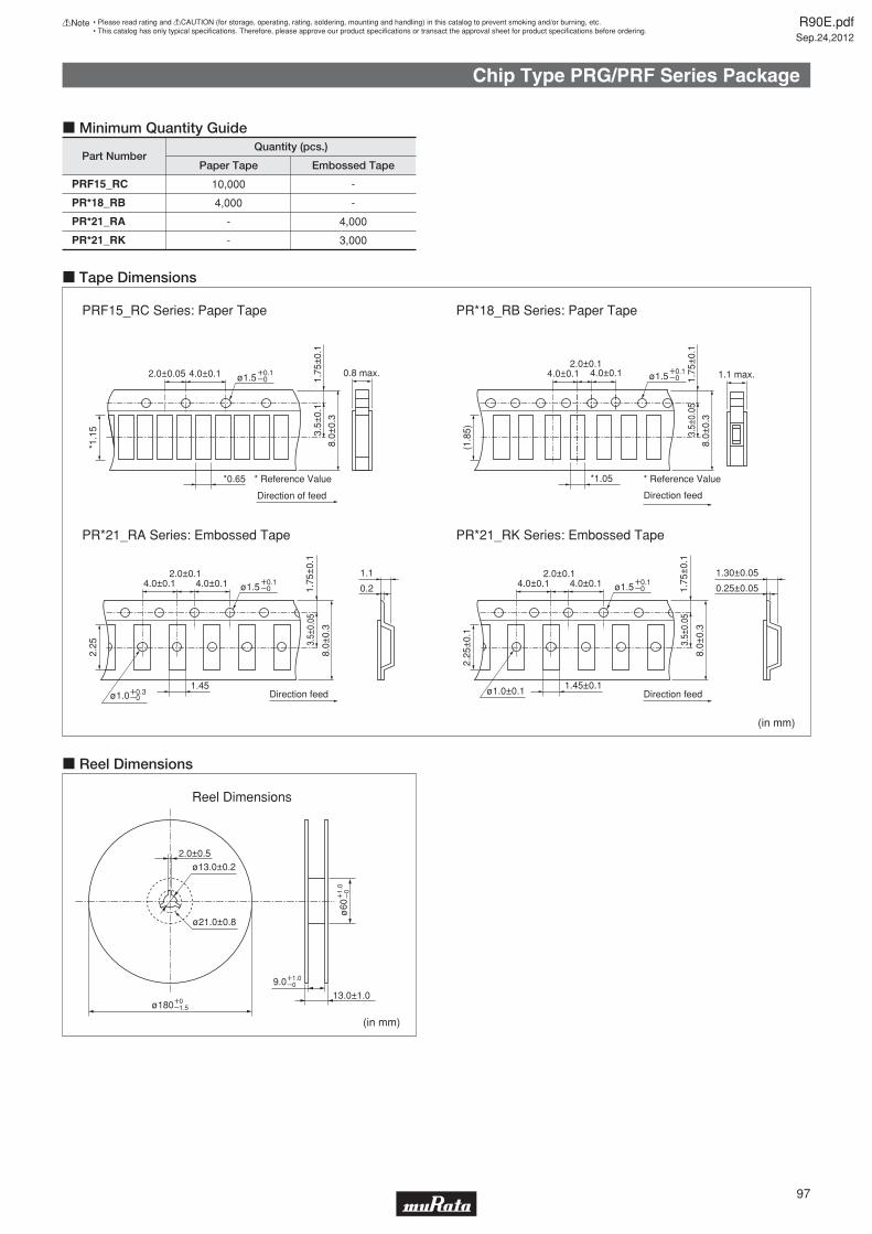
Chip Type PRG/PRF Series Package
*1.05
Direction feed
1.1 max.1.75
±0.
1
4.0±0.12.0±0.1
4.0±0.1
3.5±
0.05
8.0±
0.3
(1.8
5)
(in mm)
(in mm)
ø13.0±0.2
ø21.0±0.8
9.0
ø60
ø180W0Y1.5
W1.
0Y
0
W1.0Y0
2.0±0.5
13.0±1.0
Reel Dimensions
Part NumberQuantity (pcs.)
Paper Tape Embossed Tape
PRF15_RC
PR*18_RB
PR*21_RA
PR*21_RK
10,000
4,000
-
-
-
-
4,000
3,000
1.45±0.1Direction feed
1.75
±0.
1
4.0±0.1 4.0±0.12.0±0.1
3.5±
0.05
8.0±
0.3
ø1.5W0.1Y0
2.25
±0.
1
ø1.0±0.1
1.30±0.05
0.25±0.05
1.45Direction feed
1.75
±0.
1
4.0±0.1 4.0±0.12.0±0.1
3.5±
0.05
8.0±
0.3
ø1.0W0.3Y0
ø1.5W0.1Y0
2.25
1.1
0.2
PRF15_RC Series: Paper Tape PR*18_RB Series: Paper Tape
PR*21_RA Series: Embossed Tape PR*21_RK Series: Embossed Tape
c Minimum Quantity Guide
c Tape Dimensions
c Reel Dimensions
*0.65
Direction of feed
* Reference Value * Reference Value
0.8 max.
1.75
±0.
1
2.0±0.05 4.0±0.1
3.5±
0.1
8.0±
0.3
ø1.5W0.1Y0
*1.1
5
ø1.5W0.1Y0
R90E.pdfSep.24,2012
97
!Note • Please read rating and !CAUTION (for storage, operating, rating, soldering, mounting and handling) in this catalog to prevent smoking and/or burning, etc.• This catalog has only typical specifi cations. Therefore, please approve our product specifi cations or transact the approval sheet for product specifi cations before ordering.

Lead Type PTGL/PTF Series Package
SeriesPart Number Min. Qty. Min. Qty.Part Number
Bulk Type
Narrow Current Band 30V series
Narrow Current Band 51V series
Narrow Current Band 60V series
Narrow Current Band 140V series
16V Series
24V Series
30V Series
32V Series
56V Series
500
300
500
300
500
300
500
300
500
300
500
500
300
500
500
300
PTGL04AS100K2B51B0
PTGL04AS100K2N51B0
PTGL05AS3R9K2B51B0
PTGL07AS2R7K2B51B0
PTGL07AS1R8K2B51B0
PTGL09AS1R2K2B51B0
PTGL12AS0R8K2B51B0
PTGL04AS100K3B51B0
PTGL05AS6R8K3B51B0
PTGL07AS3R3K3B51B0
PTGL09AS2R2K3B51B0
PTGL12AS1R2K3B51B0
PTGL04AS220K4B51B0
PTGL04AS220K4N51B0
PTGL05AS100K4B51B0
PTGL07AS5R6K4B51B0
PTGL07AS5R6K4N51B0
PTGL09AS3R3K4B51B0
PTGL12AS2R2K4B51B0
PTGL04AS560K6B51B0
PTGL05AS270K6B51B0
PTGL07AS150K6B51B0
PTGL09AS120K6B51B0
PTGL09AS7R6K6B51B0
PTGL12AS4R7K6B51B0
PTGL05AR1R0M1B51B0
PTGL06AR0R8M1B51B0
PTGL07ARR47M1B51B0
PTGL09ARR33M1B51B0
PTGL10ARR27M1B51B0
PTGL12AR0R2M1B51B0
PTGL14ARR15M1B51B0
PTGL07BD100N2B51B0
PTGL07BD6R8N2B51B0
PTGL09BD4R7N2B51B0
PTGL09BD3R3N2B51B0
PTGL09BD2R2N2B51B0
PTGL04AR130H2B51B0
PTGL07AR4R6H2B51B0
PTGL09AR1R8H2B51B0
PTGL12AR1R2H2B51B0
PTGL13AR0R8H2B71B0
PTGL07BD470N3B51B0
PTGL07BD330N3B51B0
PTGL07BD220N3B51B0
PTGL07BD150N3B51B0
PTGL07AR220M3P51B0
PTGL07AR8R2M3P51B0
PTGL09AR150M3B51B0
PTGL10AR3R9M3P51B0
PTGL09AR4R7M3B51B0
PTGL10AR3R9M3B51B0
PTGL14AR3R3M3B71B0
Ammo Pack Taping Type
1500
1500
1500
1500
2000
-
1500
1500
-
-
1500
1500
-
PTGL04AS100K2B51A0
PTGL04AS100K2N51A0
PTGL05AS3R9K2B51A0
PTGL07AS2R7K2B51A0
PTGL07AS1R8K2B51A0
PTGL09AS1R2K2B51A0
PTGL12AS0R8K2B51A0
PTGL04AS100K3B51A0
PTGL05AS6R8K3B51A0
PTGL07AS3R3K3B51A0
PTGL09AS2R2K3B51A0
PTGL12AS1R2K3B51A0
PTGL04AS220K4B51A0
PTGL04AS220K4N51A0
PTGL05AS100K4B51A0
PTGL07AS5R6K4B51A0
PTGL07AS5R6K4N51A0
PTGL09AS3R3K4B51A0
PTGL12AS2R2K4B51A0
PTGL04AS560K6B51A0
PTGL05AS270K6B51A0
PTGL07AS150K6B51A0
PTGL09AS120K6B51A0
PTGL09AS7R6K6B51A0
PTGL12AS4R7K6B51A0
PTGL05AR1R0M1B51A0
PTGL06AR0R8M1B51A0
PTGL07ARR47M1B51A0
PTGL09ARR33M1B51A0
PTGL10ARR27M1B51A0
PTGL12AR0R2M1B51A0
-
PTGL07BD100N2B51A0
PTGL07BD6R8N2B51A0
PTGL09BD4R7N2B51A0
PTGL09BD3R3N2B51A0
PTGL09BD2R2N2B51A0
PTGL04AR130H2B51A0
PTGL07AR4R6H2B51A0
PTGL09AR1R8H2B51A0
-
-
PTGL07BD470N3B51A0
PTGL07BD330N3B51A0
PTGL07BD220N3B51A0
PTGL07BD150N3B51A0
PTGL07AR220M3P51A0
PTGL07AR8R2M3P51A0
PTGL09AR150M3B51A0
PTGL10AR3R9M3P51A0
PTGL09AR4R7M3B51A0
PTGL10AR3R9M3B51A0
-
80V Series
125V Series
140V Series
250V Series
265V Series
500
300
500
300
250
150
100
500
300
250
200
150
-
-
-
500
300
200
150
100
PTGL05AR550H4P51B0
PTGL07AR250H4B51B0
PTGL09AR9R4H4B51B0
PTGL12AR5R6H4B71B0
PTGL13AR3R7H4B71B0
PTGL05AR181M7P52B0
PTGL07AR750M7B52B0
PTGL09AR470M6B52B0
PTGL09AR220M6B52B0
PTGL12AR150M6B72B0
PTGL14AR100M6B72B0
PTGL18AR6R8M6B72B0
PTGL18AR4R7M6B72B0
PTGL18AR3R3M6B72B0
PTGL07AR330M6A51B0
PTGL09AR220M6C61B0
PTGL10AR150M6C61B0
PTGL12AR100M6C01B0
PTGL13AR6R8M6C01B0
PTGL16AR5R6M6C01B0
-
-
-
PTGL05AR151H8P52B0
PTGL05AR181M9N51B0
PTGL05AR121M9N51B0
PTGL07AR820M9A51B0
PTGL07AR700H8B52B0
PTGL07AR650H8B52B0
PTGL07AR450H8B52B0
PTGL07AR560M9A51B0
PTGL09AR390M9C61B0
PTGL09AR250H8B52B0
PTGL12AR270M9C01B0
PTGL12AR150H8B72B0
PTGL14AR180M9C01B0
PTGL13AR100H8B72B0
PTGL18AR6R0H8B72B0
1500
-
-
1500
1000
-
-
-
-
-
-
-
-
-
-
-
1000
1000
-
-
-
1000
1000
1000
-
-
1000
-
-
-
-
-
PTGL05AR550H4P51A0
PTGL07AR250H4B51A0
PTGL09AR9R4H4B51A0
-
-
PTGL05AR181M7P52A0
PTGL07AR750M7B52A0
PTGL09AR470M6B52A0
PTGL09AR220M6B52A0
-
-
-
-
-
-
-
-
-
-
-
PTGL07BB220N0B52A0
PTGL09AR390N0B52A0
PTGL10BB120N0P52A0
PTGL05AR151H8P52A0
-
-
-
PTGL07AR700H8B52A0
PTGL07AR650H8B52A0
PTGL07AR450H8B52A0
-
-
PTGL09AR250H8B52A0
-
-
-
-
-
SeriesPart Number Min. Qty. Min. Qty.Part Number
Bulk Type Ammo Pack Taping Type
c Minimum Order Quantity (for Overcurrent Protection)
Less than 100μF Series
100μF or more Series
500
500
500
150
150
150
150
150
100
100
PTGL07AS121M0N51B0
PTGL07AS181M0N51B0
PTGL07AS201M0N51B0
PTGL14AS470H0B02BZ
PTGL16AS330H0B02BZ
PTGL16AS470H0B02BZ
PTGL16AS680H0B02BZ
PTGL16AS101H0B02BZ
PTGL20AS330H0D02BZ
PTGL20AS470H0D02BZ
1000
1000
1000
-
-
-
-
-
-
-
PTGL07AS121M0N51A0
PTGL07AS181M0N51A0
PTGL07AS201M0N51A0
-
-
-
-
-
-
-
PTF Series400
200
PTFL Series
PTFM Series
-
-
-
-
c Minimum Order Quantity (for Inrush Current Suppression)
c Minimum Order Quantity (for Overheat Sensing)
Continued on the following page.
R90E.pdfSep.24,2012
98
!Note • Please read rating and !CAUTION (for storage, operating, rating, soldering, mounting and handling) in this catalog to prevent smoking and/or burning, etc.• This catalog has only typical specifi cations. Therefore, please approve our product specifi cations or transact the approval sheet for product specifi cations before ordering.
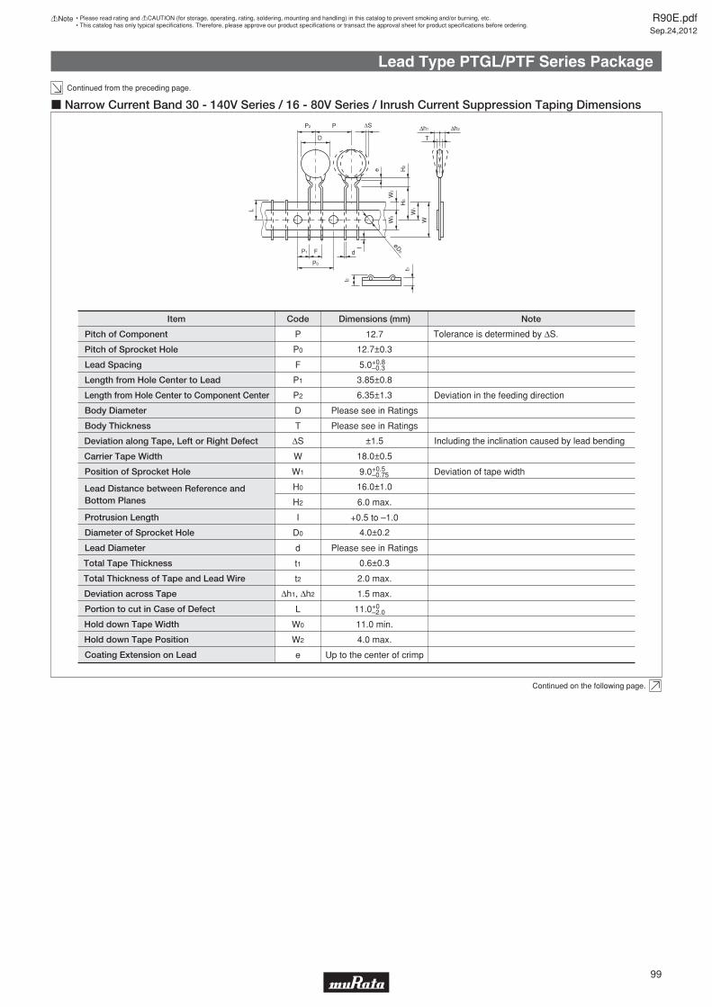
Lead Type PTGL/PTF Series Package
Continued from the preceding page.
Pitch of Component
Pitch of Sprocket Hole
Lead Spacing
Length from Hole Center to Lead
Length from Hole Center to Component Center
Body Diameter
Body Thickness
Deviation along Tape, Left or Right Defect
Carrier Tape Width
Position of Sprocket Hole
Lead Distance between Reference and Bottom Planes
Protrusion Length
Diameter of Sprocket Hole
Lead Diameter
Total Tape Thickness
Total Thickness of Tape and Lead Wire
Deviation across Tape
Portion to cut in Case of Defect
Hold down Tape Width
Hold down Tape Position
Coating Extension on Lead
P
P0
F
P1
P2
D
T
ΔS
W
W1
H0
H2
I
D0
d
t1
t2
Δh1, Δh2
L
W0
W2
e
12.7
12.7±0.3
5.0
3.85±0.8
6.35±1.3
Please see in Ratings
Please see in Ratings
±1.5
18.0±0.5
16.0±1.0
6.0 max.
+0.5 to –1.0
4.0±0.2
Please see in Ratings
0.6±0.3
2.0 max.
1.5 max.
11.0 min.
4.0 max.
Up to the center of crimp
Tolerance is determined by ΔS.
Deviation in the feeding direction
Including the inclination caused by lead bending
Deviation of tape width
CodeItem Dimensions (mm) Note
+0.8–0.3
9.0+0.5–0.75
11.0+0–2.0
W0
W2
W
W1
H0
H2
Δh2Δh1
e
ΔSP2 P
D
P1
P0
F d
l øD0
L
t2
t1
T
c Narrow Current Band 30 - 140V Series / 16 - 80V Series / Inrush Current Suppression Taping Dimensions
Continued on the following page.
R90E.pdfSep.24,2012
99
!Note • Please read rating and !CAUTION (for storage, operating, rating, soldering, mounting and handling) in this catalog to prevent smoking and/or burning, etc.• This catalog has only typical specifi cations. Therefore, please approve our product specifi cations or transact the approval sheet for product specifi cations before ordering.

Lead Type PTGL/PTF Series Package
Continued from the preceding page.
Pitch of Component
Pitch of Sprocket Hole
Lead Spacing
Length from Hole Center to Lead
Length from Hole Center to Component Center
Body Diameter
Deviation along Tape, Left or Right
Carrier Tape Width
Position of Sprocket Hole
Lead Distance between Reference andBottom Planes
Protrusion Length
Diameter of Sprocket Hole
Lead Diameter
Total Tape Thickness
Total Thickness of Tape and Lead Wire
Deviation across Tape
Portion to cut in Case of Defect
Hold down Tape Width
Hold down Tape Position
Coating Extension on Lead
P
P0
F
P1
P2
D
ΔS
W
W1
H0
H2
I
D0
d
t1
t2
Δh1, Δh2
L
W0
W2
e
12.7
12.7±0.3
5.0
3.85±0.8
6.35±1.3
Please see Ratings
Body Thickness T Please see Ratings
±1.5
18.0±0.5
16.0±1.0
6.0 max.
W0.5 to Y1.0
4.0±0.2
0.6±0.05
0.6±0.3
2.0 max.
1.5 max.
11.0 min.
4.0 max.
Up to the center of crimp
Tolerance is determined by ΔS.
Deviation in the feeding direction
Including the inclination caused by lead bending.
Deviation of tape width.
CodeItem Dimensions (mm) Note
+0.8–0.3
9.0+0.5–0.75
11.0+0–2.0
W0
W2
W
W1
H0
H2
Δh2Δh1
e
ΔSP2 P
D
P1
P0
F d
l øD0
L
t2
t1
T
c 125/250/265V Series Taping Dimensions
R90E.pdfSep.24,2012
100
!Note • Please read rating and !CAUTION (for storage, operating, rating, soldering, mounting and handling) in this catalog to prevent smoking and/or burning, etc.• This catalog has only typical specifi cations. Therefore, please approve our product specifi cations or transact the approval sheet for product specifi cations before ordering.

!Note R90E.pdfSep.24,2012
• Please read rating and !CAUTION (for storage, operating, rating, soldering, mounting and handling) in this catalog to prevent smoking and/or burning, etc.• This catalog has only typical specifi cations. Therefore, please approve our product specifi cations or transact the approval sheet for product specifi cations before ordering.

![DATASHEET SEARCH SITE == - pdf-file.ic37.compdf-file.ic37.com/uploadpdf_old/icpdf_datasheet_5/EA200_datasheet... · 5、读eeprom [eeADRR][ eeADRRack][数据] 共3 字节 [ eeADRRack]、[数据]为两个读出的数据](https://img.dokumen.tips/doc/110x75/5e05831ca5987e42f32de560/datasheet-search-site-pdf-fileic37compdf-fileic37comuploadpdfoldicpdfdatasheet5ea200datasheet.jpg)