Embed Size (px)
Citation preview
PCM 81Digital Effects Processor User Guide
A Harman International Company

UNPACKING AND INSPECTIONAfter unpacking the PCM 81, save all packing materials in case you ever need to ship the unit. Thoroughly inspect the PCM 81 and packing materials for signsof damage. Report any shipment damage to the carrier at once; report equipment malfunction to your dealer.
PRECAUTIONSSave these instructions for later use.
Follow all instructions and warnings marked on the unit.
Always use with the correct line voltage. Refer to the manufacturer's operating instructions for power requirements. Be advised that different operating voltagesmay require the use of a different line cord and/or attachment plug.
Do not install the unit in an unventilated rack, or directly above heat producing equipment such as power amplifiers. Observe the maximum ambient operatingtemperature listed in the product specification.
Slots and openings on the case are provided for ventilation; to ensure reliable operation and prevent it from overheating, these openings must not be blockedor covered. Never push objects of any kind through any of the ventilation slots. Never spill a liquid of any kind on the unit.
This product is equipped with a 3-wire grounding type plug. This is a safety feature and should not be defeated.
Never attach audio power amplifier outputs directly to any of the unit's connectors.
To prevent shock or fire hazard, do not expose the unit to rain or moisture, or operate it where it will be exposed to water.
Do not attempt to operate the unit if it has been dropped, damaged, exposed to liquids, or if it exhibits a distinct change in performance indicating the needfor service.
This unit should only be opened by qualified service personnel. Removing covers will expose you to hazardous voltages.
This triangle, which appears on your component,alerts you to the presence of uninsulated,dangerous voltage inside the enclosure -
voltage that may be sufficient toconstitute a risk of shock.
CAUTIONRISK OF ELECTRIC SHOCK
DO NOT OPEN
This triangle, which appears on your component,alerts you to important operating andmaintenance instructions in this
accompanying literature.
A Harman International Company
Lexicon, Inc.3 Oak ParkBedford, MA 01730-1441 USATel 781-280-0300Fax 781-280-0490www.lexicon.com
Customer SupportTel 781-280-0300Fax 781-280-0495 (Sales)Fax 781-280-0499 (Service)
Lexicon Part No. 070-12614 | Rev 2 | 09/01
© 2001 Lexicon, Inc. All rights reserved.
This document should not be construed as a commitment on the part of Lexicon, Inc. The information it contains is subject to change without notice. Lexicon, Inc.assumes no responsibility for errors that may appear within this document.
NOTICEThis equipment generates and uses radio frequency energy and if not installed and used properly, that is, in strict accordance with themanufacturer's instructions, may cause interference to radio and television reception. It has been type tested and found to comply with thelimits for a Class B computing device in accordance with the specifications in Part 15 of FCC Rules, which are designated to providereasonable protection against such interference in a residential installation. However, there is no guarantee that interference will not occur ina particular installation. If this equipment does cause interference to radio or television reception, which can be determined by turning theequipment OFF and ON, the user is encouraged to try to correct the interference by one or more of the following measures:
Reorient the receiving antenna
Relocate the computer with respect to the receiver
Move the computer away from the receiver
Plug the computer into a different outlet so that the computer and receiver are on different branch circuits.
If necessary, the user should consult the dealer or an experienced radio/television technician for additional suggestions. The user may find thefollowing booklet prepared by the Federal Communications Commission helpful:
"How to identify and Resolve Radio/TV Interference Problems."
This booklet is available from the U.S. Government Printing Office, Washington, DC 20402, Stock No. 004-000-00345-4.
Le présent appareil numérique n'émet pas de bruits radioélectriques dépassant les limites applicables aux appareils numériques de la class Bprescrites dans le Règlement sur le brouillage radioélectrique édicté par le ministère des Communications du Canada.

ii
Introduction Lexicon
Introduction
Vigtig information om sikkerhed .....................................iv
Tärkeitä turvallisuusohjeita...............................................iv
Viktig informasjon om sikkerhet .......................................v
Viktiga säkerhetsföreskrifter ..............................................v
Wichtige Sicherheitsanweisungen....................................vi
Instrucciones importantes de seguridad ..........................vi
Instructions de Sûreté Importantes .................................vii
Importanti norme di sicurezza ........................................vii
Section 1: Getting Started
About the PCM 81 ....................................................................1-2The Presets • The Algorithms • Tempo Control • Editing •Memory Cards • User Interface
Front Panel Overview ................................................................1-4
Rear Panel Overview..................................................................1-6
Block Diagram...........................................................................1-8
Installation Notes ......................................................................1-9Mounting • Power Requirements • Audio Connections •Control Connections • Connectors • Setting Audio Levels •Configurations • Memory Cards
Section 2: Basic Operation
Modes of Operation..................................................................2-2Navigating a Matrix • Go or Pro • Info
Control Mode ...........................................................................2-5Row 0 Audio • Row 1 System • Row 2 Card • Row 3 MIDI •Row 4 Setup • Row 5 Mapx • Row 6 Chain
Section 2: Basic Operation (continued)
Program and Register Banks....................................................2-17Selecting Effects
Tempo Mode ..........................................................................2-19The Tempo Mode Matrix • Row 0 Tempo • Row 1 Tap
Editing an Effect ......................................................................2-21The Soft Knob • The Soft Row • Compare • Bypass • StoreOperations • The Full Edit Matrix • Patching
Section 3: Algorithms and Parameters
About the Algorithms................................................................3-2The 4-Voice Algorithms .............................................................3-2
Concert Hall • Plate • Chamber • Inverse • Infinite
The 6-Voice Algorithms .............................................................3-9Glide>Hall • Chorus+Rvb • M-Band+Rvb
The Resonant Chord Algorithms..............................................3-13Res1>Plate and Res2>Plate
The Parameters .......................................................................3-15Chorus • Controls • Delay Time • Feedback/Cross Feedback •Filters • Glide FX • Levels • Modulation • Panning • Patching •Pitch • Resonance • Rvb Design • Rvb Time
The Pitch Algorithms...............................................................3-33About the Pitch Algorithms • About Pitch Shifting • Quad>Hall • Dual-Chamb • Dual-Plt • Dual-Inv • Stereo-Chmb •VSO-Chmb • The Pitch Parameters
Using the Submixer.................................................................3-45Sends • Returns • Routing • Useful Configurations
Rvb and FX Block Controls ......................................................3-52
The Pitch Correct Algorithm....................................................3-54The Pitch Correct Parameters
DK
FI
NO
SE
DE
ES
FR
IT
iii
IntroductionPCM 81
Section 4: Presets
Overview...................................................................................4-2
Program Bank 0 (P0).................................................................4-3Multi Effects • Modulation Effects • Special Effects
Program Bank 1 (P1).................................................................4-8Rhythmic Echo and Delay Effects • Ambience Effects
Program Bank 2 (P2)...............................................................4-13EQ Effects • Spatial Effects • Gain Effects • Resonant ChordEffects
Program Bank 3 (P3)...............................................................4-19Reverb Effects • Processed Reverb Effects • Remix Effects
Program Bank 4 (P4)...............................................................4-24Vocal Shift • Vocal Harmony • Guitar Magic • Instrument Shift& Harmony • Percussion & Tempo
Program Bank 5 (P5)...............................................................4-29Sci-Fi FX • Pitch & Delay • Pitch Sequences • Pads & Drones •Utility Programs • Pitch Correct
Alphabetical Index of Presets...................................................4-34
Section 5: MIDI Operation
Selecting a MIDI Channel..........................................................5-2
Accessing Programs and Registers .............................................5-2
Controlling Tempo Rate with MIDI Clock ..................................5-3MIDI Tempo Control • Using the PCM 81 as a MIDI ClockSource • Slaving Two or More PCM 81s
Controller Quirks.......................................................................5-4
The ADJUST Knob, Foot Pedal, Foot SW1, and Foot SW 2 as MIDIControllers ................................................................................5-4
Controlling the Soft Knob with MIDI • Controlling the SoftKnob with a Foot Pedal
Program Change Messages .......................................................5-5
Section 5: MIDI Operation (continued)
Automation ...............................................................................5-6
SysEx Automation • Controller Automation • Reset AllControllers • MIDI Clock and Clock Commands • PCM 90Compatibility • Dynamic MIDI
Bulk Data Dumps ......................................................................5-8
MIDI Implementation Chart ......................................................5-8
Section 6: Troubleshooting
Low Voltage ..............................................................................6-2
Overheating ..............................................................................6-2
Common MIDI Problems...........................................................6-2
Operational Problems................................................................6-3No Input • No Digital Audio Output • No Effects Output
Power On Behavior ...................................................................6-3
Restoring Factory Default Settings.............................................6-3
Reinitialization ...........................................................................6-4
Appendix
Specifications ............................................................................A-2
Declaration of Conformity.........................................................A-4
iv
Introduction Lexicon
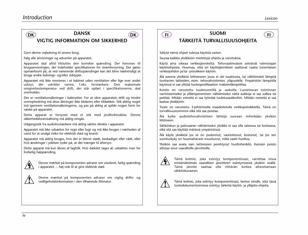
DANSKVIGTIG INFORMATION OM SIKKERHED
Gem denne vejledning til senere brug.
Følg alle anvisninger og advarsler på apparatet.
Apparatet skal altid tilsluttes den korrekte spænding. Der henvises tilbrugsanvisningen, der indeholder specifikationer for strømforsyning. Der gøresopmærksom på, at ved varierende driftsspændinger kan det blive nødvendigt atbruge andre lednings- og/eller stiktyper.
Apparatet må ikke monteres i et kabinet uden ventilation eller lige over andetudstyr, der udvikler varme, f.eks. forstærkere. Den maksimaleomgivelsestemperatur ved drift, der står opført i specifikationerne, skaloverholdes.
Der er ventilationsåbninger i kabinettet. For at sikre apparatets drift og hindreoverophedning må disse åbninger ikke blokeres eller tildækkes. Stik aldrig nogetind igennem ventilationsåbningerne, og pas på aldrig at spilde nogen form forvæske på apparatet.
Dette apparat er forsynet med et stik med jordforbindelse. Dennesikkerhedsforanstaltning må aldrig omgås.
Udgangsstik fra audioforstærkere må aldrig sættes direkte i apparatet.
Apparatet må ikke udsættes for regn eller fugt og må ikke bruges i nærheden afvand for at undgå risiko for elektrisk stød og brand.
Apparatet må aldrig bruges, hvis det er blevet stødt, beskadiget eller vådt, ellerhvis ændringer i ydelsen tyder på, at det trænger til eftersyn.
Dette apparat må kun åbnes af fagfolk. Hvis dækslet tages af, udsættes man forlivsfarlig højspænding.
Denne mærkat på komponenten advarer om uisoleret, farlig spændingi apparatet ... høj nok til at give elektrisk stød.
Denne mærkat på komponenten advarer om vigtig drifts- ogvedligeholdsinformation i den tilhørende litteratur.
SUOMITÄRKEITÄ TURVALLISUUSOHJEITA
Säilytä nämä ohjeet tulevaa käyttöä varten.
Seuraa kaikkia yksikköön merkittyjä ohjeita ja varoituksia.
Käytä aina oikeaa verkkojännitettä. Tehovaatimukset selviävät valmistajankäyttöohjeista. Huomaa, että eri käyttöjännitteet saattavat vaatia toisenlaisenverkkojohdon ja/tai -pistokkeen käytön.
Älä asenna yksikköä telineeseen jossa ei ole tuuletusta, tai välittömästi lämpöätuottavien laitteiden, esim. tehovahvistimien, yläpuolelle. Ympäristön lämpötilakäytössä ei saa ylittää tuotespesifikaation maksimilämpötilaa.
Kotelo on varustettu tuuletusreiillä ja -aukoilla. Luotettavan toiminnanvarmistamiseksi ja ylilämpenemisen välttämiseksi näitä aukkoja ei saa sulkea taipeittää. Mitään esineitä ei saa työntää tuuletusaukkoihin. Mitään nesteitä ei saakaataa yksikköön.
Tuote on varustettu 3-johtimisella maadoitetulla verkkopistokkeella. Tämä onturvallisuustoiminne eikä sitä saa poistaa.
Älä kytke audiotehovahvistimen lähtöjä suoraan mihinkään yksikönliittimeen.
Sähköiskun ja palovaaran välttämiseksi yksikkö ei saa olla sateessa tai kosteassa,eikä sitä saa käyttää märässä ympäristössä.
Älä käytä yksikköä jos se on pudonnut, vaurioitunut, kostunut, tai jos sensuorituskyky on huomattavasti muuttunut, mikä vaatii huoltoa.
Yksikön saa avata vain laitteeseen perehtynyt huoltohenkilö. Kansien poistoaltistaa sinut vaarallisille jännitteille.
Tämä kolmio, joka esiintyy komponentissasi, varoittaa sinuaeristämättömän vaarallisen jännitteen esiintymisestä yksikön sisällä.Tämä jännite saattaa olla riittävän korkea aiheuttamaansähköiskuvaaran.
Tämä kolmio, joka esiintyy komponentissasi, kertoo sinulle, että tässätuotedokumentoinnissa esiintyy tärkeitä käyttö- ja ylläpito-ohjeita.
DK DK FI FI
v
IntroductionPCM 81
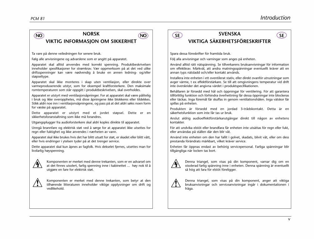
NORSKVIKTIG INFORMASJON OM SIKKERHET
Ta vare på denne veiledningen for senere bruk.
Følg alle anvisningene og advarslene som er angitt på apparatet.
Apparatet skal alltid anvendes med korrekt spenning. Produktbeskrivelseninneholder spesifikasjoner for strømkrav. Vær oppmerksom på at det ved ulikedriftsspenninger kan være nødvendig å bruke en annen ledning- og/ellerstøpseltype.
Apparatet skal ikke monteres i skap uten ventilasjon, eller direkte overvarmeproduserende utstyr, som for eksempel kraftforsterkere. Den maksimaleromtemperaturen som står oppgitt i produktbeskrivelsen, skal overholdes.
Apparatet er utstyrt med ventilasjonsåpninger. For at apparatet skal være påliteligi bruk og ikke overopphetes, må disse åpningene ikke blokkeres eller tildekkes.Stikk aldri noe inn i ventilasjonsåpningene, og pass på at det aldri søles noen formfor væske på apparatet.
Dette apparatet er utstyrt med et jordet støpsel. Dette er ensikkerhetsforanstaltning som ikke må forandres.
Utgangsplugger fra audioforsterkere skal aldri koples direkte til apparatet.
Unngå brannfare og elektrisk støt ved å sørge for at apparatet ikke utsettes forregn eller fuktighet og ikke anvendes i nærheten av vann.
Apparatet skal ikke brukes hvis det har blitt utsatt for støt, er skadet eller blitt vått,eller hvis endringer i ytelsen tyder på at det trenger service.
Dette apparatet skal kun åpnes av fagfolk. Hvis dekselet fjernes, utsettes man forlivsfarlig høyspenning.
Komponenten er merket med denne trekanten, som er en advarsel omat det finnes uisolert, farlig spenning inne i kabinettet ... høy nok til åutgjøre en fare for elektrisk støt.
Komponenten er merket med denne trekanten, som betyr at dentilhørende litteraturen inneholder viktige opplysninger om drift ogvedlikehold.
SVENSKAVIKTIGA SÄKERHETSFÖRESKRIFTER
Spara dessa föreskrifter för framtida bruk.
Följ alla anvisningar och varningar som anges på enheten.
Använd alltid rätt nätspänning. Se tillverkarens bruksanvisningar för informationom effektkrav. Märkväl, att andra matningsspänningar eventuellt kräver att enannan typs nätsladd och/eller kontakt används.
Installera inte enheten i ett oventilerat stativ, eller direkt ovanför utrustningar somavger värme, t ex effektförstärkare. Se till att omgivningens temperatur vid driftinte överskrider det angivna värdet i produktspecifikationen.
Behållaren är försedd med hål och öppningar för ventilering. För att garanteratillförlitlig funktion och förhindra överhettning får dessa öppningar inte blockeraseller täckas. Inga föremål får skuffas in genom ventilationshålen. Inga vätskor fårspillas på enheten.
Produkten är försedd med en jordad 3-trådskontakt. Detta är ensäkerhetsfunktion som inte får tas ur bruk.
Anslut aldrig audioeffektförstärkarutgångar direkt till någon av enhetenskontakter.
För att undvika elstöt eller brandfara får enheten inte utsättas för regn eller fukt,eller användas på ställen där den blir våt.
Använd inte enheten om den har fallit i golvet, skadats, blivit våt, eller om dessprestanda förändrats märkbart, vilket kräver service.
Enheten får öppnas endast av behörig servicepersonal. Farliga spänningar blirtillgängliga när locken tas bort.
Denna triangel, som visas på din komponent, varnar dig om enoisolerad farlig spänning inne i enheten. Denna spänning är eventuelltså hög att fara för elstöt föreligger.
Denna triangel, som visas på din komponent, anger att viktigabruksanvisningar och serviceanvisningar ingår i dokumentationen ifråga.
NO NO SE SE
vi
Introduction Lexicon
DEUTSCHWICHTIGE SICHERHEITSANWEISUNGEN
Heben Sie sich diese Sicherheitsanweisungen auch für später auf.
Befolgen Sie alle auf der Vorrichtung stehenden Anweisungen und Warnungen.
Immer nur mit der richtigen Spannung verwenden! Die ebrauchsanweisungendes Herstellers informieren Sie über die elektrischen Anforderungen. VergessenSie nicht daß bei verschiedenen Betriebsspannungen ggf. auch verschiedeneLeitungskabel und/oder Verbindungsstecker zu verwenden sind.
Stellen Sie die Vorrichtung nicht in ein unbelüftetes Gestell oderunmittelbar über wärmeerzeugende Geräte wie z.B. Tonverstärker. Halten Sie diein den Produktspezifikationen angegebene maximale Umgebungstemperatur beiBetrieb ein.
Schlitze und Öffnungen im Gehäuse dienen der Belüfung; um verläßlichenBetrieb sicherzustellen und Überheizen zu vermeiden dürfen diese Öffnungennich verstopft oder abgedeckt werden. Stecken Sie nie irgend einen Gegenstanddurch die Belüftungsschlitze. Vergießen Sie keine Flüssigkeiten auf den Apparat.
Dieses Produkt is mit einem 3-drahtigen Erdungsstecker ausgerüstet. DieseSicherheitsmaßnahme darf nicht unwirksam gemacht werden.
Schließen Sie nie Tonverstärker unmittelbar an einen Anschluß des Apparates an.
Um elektrischen Schlag oder Feuer zu vermeiden, setzen Sie den Apparat wederRegen noch Feuchtigkeit aus und betreiben Sie ihn nicht dort wo Wassereindringen könnte.
Versuchen Sie nicht den Apparat zu betreiben falls er fallen gelassen, beschädigt,oder Flüssigkeiten ausgesetzt wurde, oder falls sich seine Arbeitsweise derartändert daß daraus ein Bedarf nach Raparatur zu schließen ist.
Dieser Apparat sollte nur von qualifizierten Fachleuten geöffnet werden. DasAbnehmen von Abdeckungen setzt Sie gefährlichen Spannungen aus.
Dieses Dreieck auf Ihrem Apparat warnt Sie vor nicht-isolierter,gefährlicher Spannung im Gehäuse ... stark genug um eineBerührungsgefahr darzustellen.
Dieses Dreieck auf Ihrem Apparat bedeutet daß wichtige Betriebs- undWartungsanweisungen in der mitgelieferten Dokumentation zu findensind.
ESPAÑOLINSTRUCCIONES IMPORTANTES
DE SEGURIDAD
Guarde esta instrucciones para uso posterior.
Utilice siempre el voltaje correcto. Diríjase a las instrucciones de operación delfabricante para obtener las especificaciones de potencia. Esté al tanto de quevoltajes de operación distintos requieren el uso de cables y/o enchufes distintos.
No instale esta unidad en un estante sin ventilación, ni tampoco directamenteencima de equipos que generen calor tales como amplificadores de potencia.Fíjese en las temperaturas ambientales máximas de operación que se mencionanen las especificaciones del producto.
Las aperturas y ranuras del chasis sirven para proveer la ventilación necesaria paraoperar la unidad con seguridad y para prevenir sobrecalentamiento, y por lo tantono pueden ser obstruidas o cubiertas. No introduzca objetos de ningún tipo a travésde las ranuras de ventilación, y nunca deje caer ningún líquido sobre la unidad.
Este producto está equipado con un enchufe de 3 clavijas con conexión a tierra.Éste es un elemento de seguridad que no debe ser eliminado.
Nunca conecte ningún tipo de salida de amplificadores de sonido directamentea los conectores de la unidad.
Para prevenir descargas eléctricas o incendios, mantenga la unidad alejada de lalluvia, humedad o cualquier lugar en el que pueda entrar en contacto con agua.
No trate de hacer funcionar la unidad si se ha caído, está dañada, ha entrado encontacto con líquidos, o si nota cualquier cambio brusco en su funcionamientoque indique la necesidad de hacerle un servicio de mantenimiento.
Esta unidad deberá ser abierta únicamente por personal calificado. Si usted quitalas coberturas se expondrá a voltajes peligrosos.
Este triángulo que aparece en su componente le advierte sobre laexistencia dentro del chasis de voltajes peligrosos sin aislantes ...voltajes que son lo suficientemente grandes como para causarelectrocución.
Este triángulo que aparece en su componente lo alerta sobre lasinstrucciones de operación y mantenimiento importantes que están enlos materiales de lectura que se incluyen.
DE DE ES ES
vii
IntroductionPCM 81
FRANÇAISINSTRUCTIONS DE SÛRETÉ IMPORTANTES
Gardez ces instructions pour réference future.
Observez toutes les instructions et tous les avertissements marqués sur l’appareil.
Branchez uniquements sur un réseau de tension indiquée. Consultez le manueld’instruction du fabriquant pour les spécifications de courant. N’oubliez pas quedifférentes tensions peuvent nécessiter l’utilisation de cables et/ou de fiches deconnexion différents.
N’installez pas l’appareil en un compartiment non-aéré ou directement au-dessusd’équipements générateurs de chaleur, tels qu’amplificateurs de courants, etc.Ne dépassez pas la température ambiante maximale de fonctionnement indiquéedans les spécifications du produit.
Des fentes et ouvertures sont prévues dans le boîtier pour l’aération; Pourassurer le bon fonctionnement et pour prévenir l’échauffement, ces ouvertures nedoivent pas être couvertes ou bloquées. N’insérez pas d’objets dans les fentesd’aération. Empêchez tout liquide de se répandre sur l’appareil.
Ce produit est muni d’une fiche à trois fils pour la mise à terre. Ceci est unemesure de sécurité et ne doit pas être contrariée.
Ne connectez jamais d’amplificateurs audio directement aux connecteurs del’appareil.
Pour empêcher les chocs électriques et le danger d’incendie, évitez d’exposerl’appareil à la pluie ou à l’humidité, et ne le mettez pas en marche en un endroitoù il serait exposé aux éclaboussures d’eau.
N’essayez pas de faire fonctionner l’appareil s’il est tombé à terre, a étéendommangé, exposé à un liquide, ou si vous observez des différences nettesdans son fonctionnement, indiquant la nécessité de réparations.
Cet appareil ne doit être ouvert que par un personnel de service qualifié. Enenlevant les couvercles vous vous exposez à des tensions électriques dangereuses.
Ce triangle, sur votre appareil vous avertit de la présence de tensiondangereuse, non-isolée à l’intérieur du boîtier...une tension suffisantepour représenter un danger d’électrocution.
Ce triangle sur sur votre appareil vous invite de suivre d’importantesinstructions d’utilisation et d’entretien dans la documentation livréeavec le produit.
ITALIANOIMPORTANTI NORME DI SICUREZZA
Conservare le presenti norme per l’utilizzo futuro.
Osservare tutte le istruzioni e le avvertenze apposte sull’unità.
Utilizzare esclusivamente con la tensione di rete corretta. Consultare le istruzionioperative fornite dal fabbricante per i dati riguardanti la tensione el’assorbimento di corrente. Potrebbe essere necessario l’uso di cavi di rete e/o dispine diverse a seconda della tensione utilizzata.
Non installare l’unità in uno scaffale privo di ventilazione oppure direttamentesopra una fonte di calore, come, ad esempio, un amplificatore. Non superare latemperatura ambientale massima di funzionamento riportata nei dati tecnici delprodotto.
Le fessure e le altre aperture nella scatola servono alla ventilazione. Per unfunzionamento affidabile, e per evitare un eventuale surriscaldamento, questeaperture non vanno ostruite o coperte in nessun modo. Evitare in tutti i casi diinserire oggetti di qualsiasi genere attraverso le fessure di ventilazione. Nonversare mai del liquido di nessun tipo sull’unità.
Questo prodotto viene fornito con una spina a 3 fili con massa. Tale dispositivo disicurezza non va eliminato.
Evitare sempre di collegare le uscite dell’amplificatore audio direttamente aiconnettori dell’unità.
Per prevenire il pericolo di folgorazione e di incendio non esporre l’unità allapioggia o ad un’umidità eccessiva; evitare di adoperare l’unità dove potrebbeentrare in contatto con acqua.
Evitare di adoperare l’unità se la stessa è stata urtata violentemente, se ha subitoun danno, se è stata esposta ad un liquido o in caso di un evidente cambiamentodelle prestazioni che indichi la necessità di un intervento di assistenza tecnica.
Ogni intervento sull’unità va eseguito esclusivamente da personale qualificato. Larimozione della copertura comporta l’esposizione al pericolo di folgorazione.
Il presente triangolo impresso sul componente avverte della presenzadi tensioni pericolose non isolate all’interno della copertura... talitensioni rappresentano un pericolo di folgorazione
Il presente triangolo impresso sul componente avverte l’utente dellapresenza nella documentazione allegata di importanti istruzioni relativeal funzionamento ed alla manutenzione.
FR FR IT IT
Getting Started
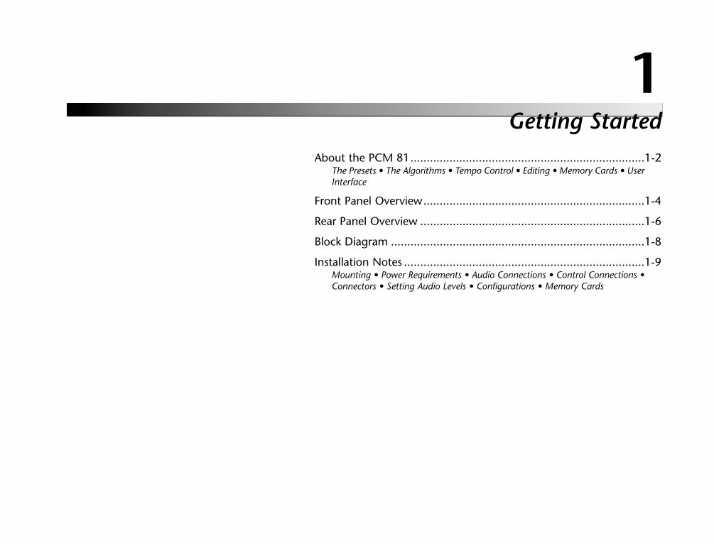
1About the PCM 81........................................................................1-2
The Presets • The Algorithms • Tempo Control • Editing • Memory Cards • UserInterface
Front Panel Overview....................................................................1-4
Rear Panel Overview .....................................................................1-6
Block Diagram ..............................................................................1-8
Installation Notes ..........................................................................1-9Mounting • Power Requirements • Audio Connections • Control Connections •Connectors • Setting Audio Levels • Configurations • Memory Cards
1-2
Getting Started Lexicon
ABOUT THE PCM 81Thank you for your purchase of the PCM 81, one of Lexicon’s mostpowerful and versatile digital effects processors. The PCM 81 bringsyou exciting new effects with extensive processing and controlcapabilities, and uncompromising sonic clarity.
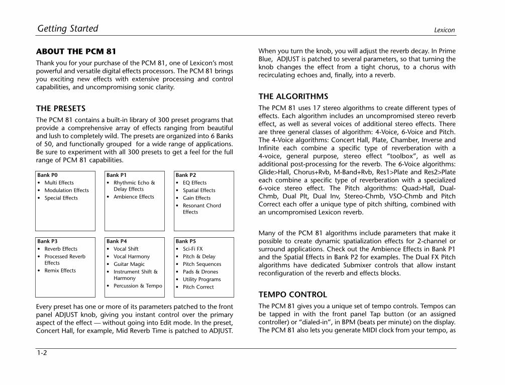
THE PRESETSThe PCM 81 contains a built-in library of 300 preset programs thatprovide a comprehensive array of effects ranging from beautifuland lush to completely wild. The presets are organized into 6 Banksof 50, and functionally grouped for a wide range of applications.Be sure to experiment with all 300 presets to get a feel for the fullrange of PCM 81 capabilities.
When you turn the knob, you will adjust the reverb decay. In PrimeBlue, ADJUST is patched to several parameters, so that turning theknob changes the effect from a tight chorus, to a chorus withrecirculating echoes and, finally, into a reverb.
THE ALGORITHMSThe PCM 81 uses 17 stereo algorithms to create different types ofeffects. Each algorithm includes an uncompromised stereo reverbeffect, as well as several voices of additional stereo effects. Thereare three general classes of algorithm: 4-Voice, 6-Voice and Pitch.The 4-Voice algorithms: Concert Hall, Plate, Chamber, Inverse andInfinite each combine a specific type of reverberation with a4-voice, general purpose, stereo effect “toolbox”, as well asadditional post-processing for the reverb. The 6-Voice algorithms:Glide>Hall, Chorus+Rvb, M-Band+Rvb, Res1>Plate and Res2>Plateeach combine a specific type of reverberation with a specialized6-voice stereo effect. The Pitch algorithms: Quad>Hall, Dual-Chmb, Dual Plt, Dual Inv, Stereo-Chmb, VSO-Chmb and PitchCorrect each offer a unique type of pitch shifting, combined withan uncompromised Lexicon reverb.
Many of the PCM 81 algorithms include parameters that make itpossible to create dynamic spatialization effects for 2-channel orsurround applications. Check out the Ambience Effects in Bank P1and the Spatial Effects in Bank P2 for examples. The Dual FX Pitchalgorithms have dedicated Submixer controls that allow instantreconfiguration of the reverb and effects blocks.
TEMPO CONTROLThe PCM 81 gives you a unique set of tempo controls. Tempos canbe tapped in with the front panel Tap button (or an assignedcontroller) or “dialed-in”, in BPM (beats per minute) on the display.The PCM 81 also lets you generate MIDI clock from your tempo, as
Bank P0• Multi Effects• Modulation Effects• Special Effects
Bank P1• Rhythmic Echo &
Delay Effects• Ambience Effects
Bank P2• EQ Effects• Spatial Effects• Gain Effects• Resonant Chord
Effects
Bank P3• Reverb Effects• Processed Reverb
Effects• Remix Effects
Bank P4• Vocal Shift• Vocal Harmony• Guitar Magic• Instrument Shift &
Harmony• Percussion & Tempo
Bank P5• Sci-Fi FX• Pitch & Delay• Pitch Sequences• Pads & Drones• Utility Programs• Pitch Correct
Every preset has one or more of its parameters patched to the frontpanel ADJUST knob, giving you instant control over the primaryaspect of the effect — without going into Edit mode. In the preset,Concert Hall, for example, Mid Reverb Time is patched to ADJUST.
1-3
Getting StartedPCM 81
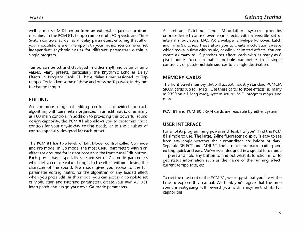
well as receive MIDI tempo from an external sequencer or drummachine. In the PCM 81, tempo can control LFO speeds and TimeSwitch controls, as well as all delay parameters, ensuring that all ofyour modulations are in tempo with your music. You can even setindependent rhythmic values for different parameters within asingle program.
Tempo can be set and displayed in either rhythmic value or timevalues. Many presets, particularly the Rhythmic Echo & DelayEffects in Program Bank P1, have delay times assigned to Taptempo. Try loading some of these and pressing Tap twice in rhythmto change tempo.
EDITINGAn enormous range of editing control is provided for eachalgorithm, with parameters organized in an edit matrix of as manyas 100 main controls. In addition to providing this powerful sounddesign capability, the PCM 81 also allows you to customize thesecontrols for your day-to-day editing needs, or to use a subset ofcontrols specially designed for each preset.
The PCM 81 has two levels of Edit Mode control called Go modeand Pro mode. In Go mode, the most useful parameters within aneffect are grouped for instant access via the front panel Edit button.Each preset has a specially selected set of Go mode parameterswhich let you make value changes to the effect without losing thecharacter of the sound. Pro mode gives you access to the fullparameter editing matrix for the algorithm of any loaded effectwhen you press Edit. In this mode, you can access a complete setof Modulation and Patching parameters, create your own ADJUSTknob patch and assign your own Go mode parameters.
A unique Patching and Modulation system providesunprecedented control over your effects, with a versatile set ofinternal modulators: LFO, AR Envelope, Envelope Follower, Latchand Time Switches. These allow you to create modulation sweepswhich move in time with music, or wildly animated effects. You cancreate as many as 10 patches per effect, each with as many as 8pivot points. You can patch multiple parameters to a singlecontroller, or patch multiple sources to a single destination.
MEMORY CARDSThe front panel memory slot will accept industry standard PCMCIASRAM cards (up to 1Meg). Use these cards to store effects (as manyas 2350 on a 1 Meg card), system setups, MIDI program maps, andmore.
PCM 81 and PCM 80 SRAM cards are readable by either system.
USER INTERFACEFor all of its programming power and flexibility, you’ll find the PCM81 simple to use. The large, 2-line fluorescent display is easy to seefrom any angle whether the surroundings are bright or dark.Separate SELECT and ADJUST knobs make program loading andediting quick and easy. We’ve even designed in a special Info mode— press and hold any button to find out what its function is, or toget status information such as the name of the running effect,current tempo rate, etc.
To get the most out of the PCM 81, we suggest that you invest thetime to explore this manual. We think you’ll agree that the timespent investigating will reward you with enjoyment of its fullcapabilities.

1-4
Getting Started Lexicon
1. Headroom
Five-position indicator for analog and digital signal levels andoverload conditions.
2. INPUT
Adjusts analog input level.
3. Display
Two rows of 20 alphanumeric characters display effect namesand ID numbers, and parameter names and values.
4. ADJUST
In Edit mode, changes values of parameters chosen withSELECT. With Program Banks or Register Banks selected,behaves as a soft knob for patched parameters.
5. SELECT
Scrolls through presets, registers or parameters. With ProgramBank or Register Bank selected, scrolls through the 50programs in the selected bank. With Edit selected, scrolls onlythrough the parameters of the active row.
6. Up/Down
Press to move up and down through a program, register, orparameter matrix.
7. Program Banks
Enables selection of factory presets. Press repeatedly to cycleselection of 4 internal preset banks. Press and hold to displaythe name of the current bank.
8. Load/
In Program or Register mode, loads the selected program. InEdit mode, scrolls through any multi-field parameter.
FRONT PANEL OVERVIEW
HEADROOM DIGITAL EFFECTS PROCESSOR ADJUSTPCM 810dB
6121824 0 10
INPUT SELECT POWERUp
ProgramBanks
RegisterBanks Edit Control Tempo
DownLoad
Compare Bypass Tap Store Memory Card
Eject
Chorus+RvbPrime BlueP0 0.0
1 2
3
4 5 6
6 8 10 12 14 16
7 9 11 13 15 18
17

1-5
Getting StartedPCM 81
9. Register Banks
Enables selection of user memory. If a RAM card is loaded intothe Memory Card slot, each press of this button selects a newregister bank. Press and hold to display the name of the currentbank.
10. Store
Initiates register store function.
11. Edit
Enables parameter selection for editing of values.
12. Compare
Active in Program, Register, and Edit modes. Press to comparethe active version of the current effect with the most recentlystored version.
13. Control
Enables selection of system and global parameters.
14. Bypass
Bypasses or mutes audio, depending on the setting of eachprogram's bypass parameter.
15. Tempo
Press to display tempo rate and to initiate tempo functions.LED flashes in time with current tempo rate.
16. Tap
Sets tempo. Press twice in rhythm to establish tempo rate.Press once to reset LFO.
17. Memory Card
Slot for optional preset ROM or register RAM cards. Press Ejectbutton to remove card.
18. POWER
On/Off.

1-6
Getting Started Lexicon
1. AC Power
Standard 3-pin IEC power connector. 100-240V, 50-60Hzautomatic switching to correct voltage range.
2. MIDI INReceives MIDI information from other MIDI equipment such asmaster keyboard controllers, MIDI foot controllers, sequencersand synthesizers.
MIDI THRUPasses any MIDI data received without change.
MIDI OUTTransmits MIDI data to other equipment.
3. AES/EBU and S/PDIF Inputs
AES/EBU format digital connectors conform to AESprofessional standards. S/PDIF format digital connectorsconform to CP-340 Type II and IEC-958 consumer standards.Only one of these options (AES or S/PDIF) may be selected forinput.
4. FOOTSWITCH
A 1/4” Tip/Ring/Sleeve phone jack for two independentmomentary footswitches.
5. FOOT CONTROLLER
A 1/4" Tip/Ring/Sleeve phone jack provided for footpedal with10kΩ to 100Ω impedance.
REAR PANEL OVERVIEW
MIDI
BALANCED INPUTS
FOOTSWITCH
L RIN
MIDIAES/EBU
THRU OUT
OUT IN
FOOTCONTROLLER
BALANCED OUTPUTS
INPUTSBALANCED
INPUTLEVELL R
S/PDIF
IN
OUT
UNBAL-20dB
0dB
PUSHPUSHPUSHPUSH PUSHPUSH
1 5
2
3
64 8
7
1-7
Getting StartedPCM 81
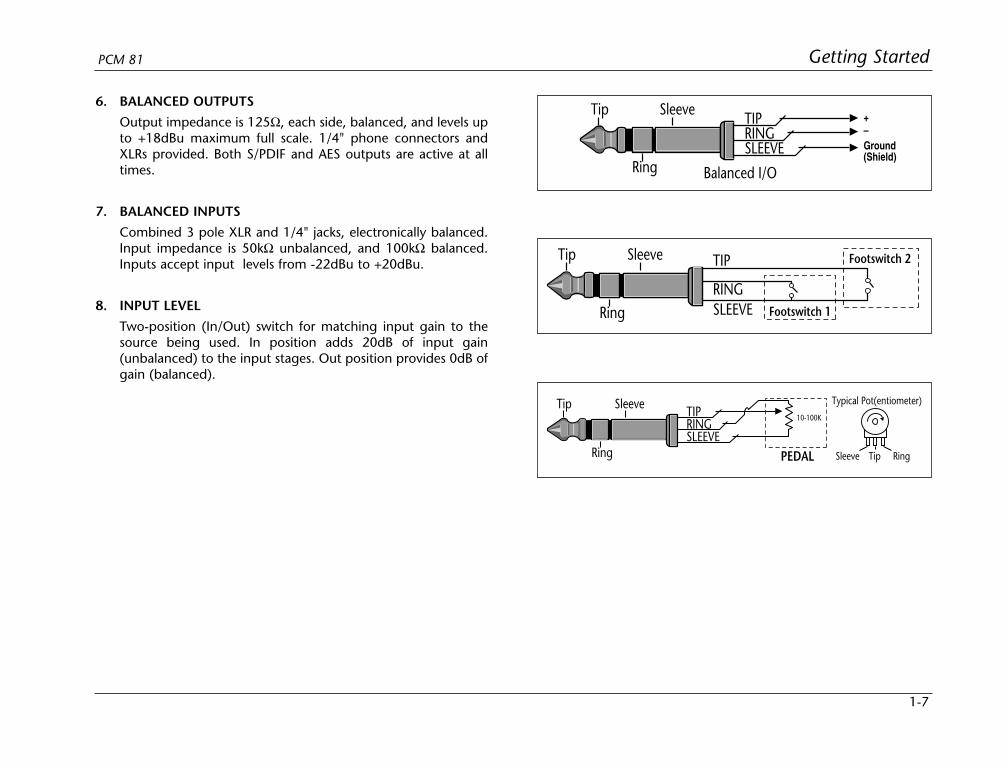
6. BALANCED OUTPUTS
Output impedance is 125Ω, each side, balanced, and levels upto +18dBu maximum full scale. 1/4" phone connectors andXLRs provided. Both S/PDIF and AES outputs are active at alltimes.
7. BALANCED INPUTS
Combined 3 pole XLR and 1/4" jacks, electronically balanced.Input impedance is 50kΩ unbalanced, and 100kΩ balanced.Inputs accept input levels from -22dBu to +20dBu.
8. INPUT LEVEL
Two-position (In/Out) switch for matching input gain to thesource being used. In position adds 20dB of input gain(unbalanced) to the input stages. Out position provides 0dB ofgain (balanced).
TIPRINGSLEEVE
Tip Sleeve
Ring PEDAL
10-100K
Typical Pot(entiometer)
TipSleeve Ring
TIP
RINGSLEEVE
Tip Sleeve
Ring
Footswitch 2
Footswitch 1
TIPRINGSLEEVE
Tip Sleeve
Ring
+–Ground(Shield)
Balanced I/O
1-8
Getting Started Lexicon
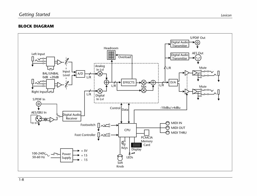
BLOCK DIAGRAM
Left Input
InputLevel
Digital AudioReceiver
PowerSupply
+ 5V
+ 15
Mute
- 15
MIDI IN
A/DL/R
L/R
L/R
AnalogIn Lvl
Headroom
DigitalIn Lvl
EFFECTS
Overload
-10dBu/+4dBu
D/A
S/PDIF In
AES/EBU In
100-240V50-60 Hz
BAL/UNBAL0dB +20dB
Right Input
S/PDIF Out
Footswitch
Foot Controller
CPU
Control Data
SoftKnob
Keys
LEDs
Display
PCMCIAMemory
Card
Mute
MIDI OUT
MIDI THRU
Mix L/R
L/R
AES Out
Digital AudioTransmitter
Digital AudioTransmitter
1-9
Getting StartedPCM 81
INSTALLATION NOTES
MOUNTINGThe PCM 81 uses one EIA-standard rack space, and can bemounted on any level surface or in a standard 19 inch (483 mm)rack. If the PCM 81 is mounted in a rack or road case, support therear of the chassis to prevent possible damage from mechanicalshock and vibration.
The maximum ambient operating temperature is 104°F (40°C).Provide adequate ventilation if the PCM 81 is mounted in a closedrack with heat-producing equipment such as power amplifiers.
POWER REQUIREMENTSThe PCM 81 is equipped with a 3-pin IEC power connector anddetachable cord.
The PCM 81 will operate with power sources from 100 to 240 voltsAC, 50-60Hz. Power switching to actual line voltage is automatic.
AUDIO CONNECTIONS
Analog AudioFor best performance, maintain balanced connections, and usehigh-quality, low-capacitance, twisted-shielded pair cable.
When connecting to single-ended, unbalanced devices, connectthe low side to signal ground at the unbalanced piece ofequipment. Output level does not change when connected to anunbalanced input.
Mono ApplicationsUse a Y-connector inserted at the analog inputs and outputs tohave the signal summed to mono.
Note:Be careful to keep input and output to all channelswired consistently. Out-of-phase wiring can produceaudible effects.
Digital AudioS/PDIF (CP-340 Type II) Consumer Digital Audio connectionsrequire 75Ω coaxial cable suited for digital audio or video signals.Audio grade cable is not suitable.
AES/EBU connections require balanced connections usinghigh-quality, low-capacitance, controlled-impedance, datacommunication, twisted-shielded pair cable. Microphone cablemay introduce a significant amount of jitter into the signal, causingdistortion.
CONTROL CONNECTIONS
Footswitch/Foot ControllerOne 1/4 inch T/R/S phone jack is provided for 2 momentaryfootswitches. Another 1/4 inch T/R/S phone jack is provided for afootpedal (minimum 100Ω to maximum 10k impedance).Normally open or normally closed momentary switches aresuitable. At power on, the PCM 81 assumes the switch is off. Useshielded, twisted-pair cable with shield connected to sleeve. Seediagram on page 1-9.
1-10
Getting Started Lexicon
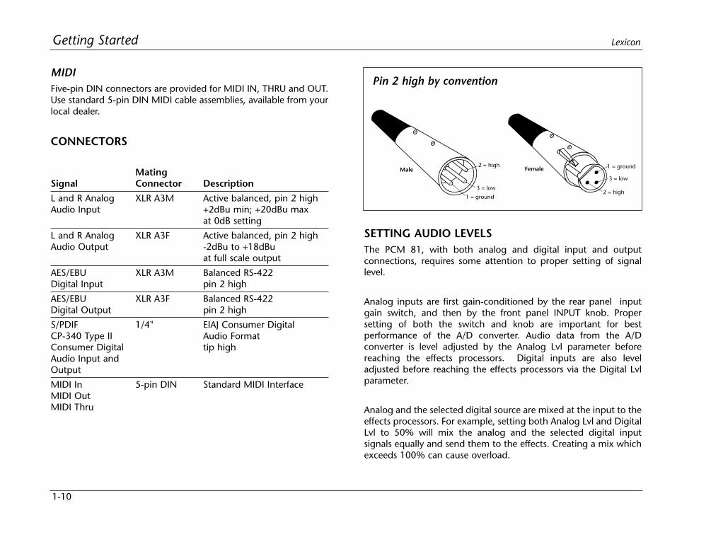
MIDIFive-pin DIN connectors are provided for MIDI IN, THRU and OUT.Use standard 5-pin DIN MIDI cable assemblies, available from yourlocal dealer.
CONNECTORS
MatingSignal Connector Description
L and R Analog XLR A3M Active balanced, pin 2 highAudio Input +2dBu min; +20dBu max
at 0dB setting
L and R Analog XLR A3F Active balanced, pin 2 highAudio Output -2dBu to +18dBu
at full scale output
AES/EBU XLR A3M Balanced RS-422Digital Input pin 2 high
AES/EBU XLR A3F Balanced RS-422Digital Output pin 2 high
S/PDIF 1/4" EIAJ Consumer DigitalCP-340 Type II Audio FormatConsumer Digital tip highAudio Input andOutput
MIDI In 5-pin DIN Standard MIDI InterfaceMIDI OutMIDI Thru
SETTING AUDIO LEVELSThe PCM 81, with both analog and digital input and outputconnections, requires some attention to proper setting of signallevel.
Analog inputs are first gain-conditioned by the rear panel inputgain switch, and then by the front panel INPUT knob. Propersetting of both the switch and knob are important for bestperformance of the A/D converter. Audio data from the A/Dconverter is level adjusted by the Analog Lvl parameter beforereaching the effects processors. Digital inputs are also leveladjusted before reaching the effects processors via the Digital Lvlparameter.
Analog and the selected digital source are mixed at the input to theeffects processors. For example, setting both Analog Lvl and DigitalLvl to 50% will mix the analog and the selected digital inputsignals equally and send them to the effects. Creating a mix whichexceeds 100% can cause overload.
2 = high
3 = low
1 = ground
1 = ground
3 = low
2 = high
FemaleMale
Pin 2 high by convention

1-11
Getting StartedPCM 81
Proper setting of Input level on the PCM 81 is dependent on:
• Proper signal level into the analog front end to avoid signalscausing overload at the DSP input
• Proper adjustment of the signal level into the analog-to-digitalconverter to optimize noise and avoid overload
• Proper setting of signal level into the digital signal processor tooptimize noise.
Headroom DisplayThe headroom display provides bothheadroom and overload information from avariety of measurement points. The metersdisplay the sum of both the analog and thedigital input data. Examining either theanalog or the digital level alone requires that
the Level parameter of the subject data stream be set to 100%,while the Level parameter of the other is set to 0%.
The chart below illustrates the adjustment range that will set inputlevels for both balanced and unbalanced operation.When a choicecan be made, it is best to operate at the higher amplitude end ofthe recommended range to optimize noise performance.
Unbalanced Balanced
overload: >0dBu >+20dBu
acceptable: 0dBu to -22dBu +20dBu to -2dBu
too low (noisy): <-22dBu <-2dBu
OverloadThe 0db (overload) indicators will light under the followingconditions:
• A/D overload
• Overload at any point in effects processing
For example, internal peaking of high Q filters, or level buildupfrom certain reverberation modes can result in overload, evenwhen the input A/D or digital receiver data stream is not at fullscale. Such conditions are most often caused by a combination ofextreme parameter settings. Adjusting parameter/level settings caneliminate these overload conditions.
Selecting a Digital Input Source1. Press Control.
2. Press Up or Down until the leftmost digit in the lower lefthandcorner of the display is 0.
3. Turn SELECT to 0.0 Word Clock, and turn ADJUST to displayExt: XLR or Ext: Coax, depending on the input you are using.
Selecting Word Size1. Press Control.
2. Press Up or Down until the leftmost digit in the lower lefthandcorner of the display is 0.
3. Turn SELECT to 0.3 Word Size, and turn ADJUST to displaydesired Word Size.
• When using analog outputs as primary outputs, set Word Sizeto 20 bits.
HEADROOM0dB
6121824 0 10
INPUT
1-12
Getting Started Lexicon
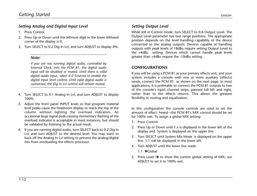
Setting Analog and Digital Input Level1. Press Control.
2. Press Up or Down until the leftmost digit in the lower lefthandcorner of the display is 0.
3. Turn SELECT to 0.2 Dig In Lvl, and turn ADJUST to display 0%.
Note:If you are not running digital audio, controlled byExternal Clock, into the PCM 81, the digital audioinput will be disabled or muted. Until there is validdigital audio input, select 0.0 External to enable thedigital input level control. Until valid digital audio isconnected, the Dig In Lvl control will remain muted.
4. Turn SELECT to 0.1 Analog In Lvl, and turn ADJUST to display100%.
5. Adjust the front panel INPUT knob so that program materiallevel peaks cause the headroom display to reach the top of thecolumn without lighting the overload indicators. Anoccasional large signal peak causing momentary flashing of theoverload indicator is acceptable in most instances, but shouldbe validated by listening to the actual result.
6. If you are running digital audio, turn SELECT back to 0.2 Dig InLvl, and turn ADJUST to the desired level. You may want toback off the Analog In Lvl setting to prevent the analog/digitalmix from overloading the effects processor.
Setting Output LevelWhile still in Control mode, turn SELECT to 0.6 Output Level. TheOutput Level parameter has two range positions. The appropriateposition depends on the level handling capability of the deviceconnected to the analog outputs. Devices capable of handlingoutputs with peak levels of 18dBu require setting Output Level tothe +4dBu setting. Devices which cannot handle peak levelsgreater than +4dBu require the -10dBu setting.
CONFIGURATIONSIf you will be using a PCM 81 as your primary effects unit, and yoursystem includes a console with one or more auxiliary (effects)sends, connect the PCM 81 as shown on the next page. In mostapplications, it is preferable to connect the PCM 81 outputs to twoof the console's input channel strips, panned full left and right,rather than to the effects returns. This allows the greatestflexibility in routing and equalization.
In this configuration the console controls are used to set theamount of effect heard—the PCM 81's MIX control should be setfor 100% wet. To assign a global MIX setting:
1. Press Control.
2. Press Up or Down until 1.x is displayed in the lower left of thedisplay and System is displayed on the upper line.
3. Turn SELECT until System Mix Mode is displayed on the upperline. 1.1 will be displayed in the lower left.
4. Turn ADJUST until the lower line reads:
1.1 Global
5. Press Load / to show the current global setting of MIX; useADJUST to set it to 100% wet.
1-13
Getting StartedPCM 81
MIDI
Effects Send (R)
Effects Send (L)
Channel Input orEffects Return (R)
Channel Input orEffects Return (L)
FOOTSWITCH
L RIN
MIDIAES/EBU
THRU OUT
OUT IN
FOOTCONTROLLER BALANCED OUTPUTS
INPUTSBALANCED
INPUTLEVELL R
S/PDIF
IN
OUT
UNBAL-20dB
0dB
PUSHPUSHPUSHPUSH PUSHPUSH
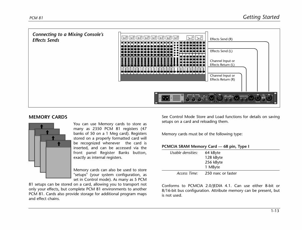
MEMORY CARDSYou can use Memory cards to store asmany as 2350 PCM 81 registers (47banks of 50 on a 1 Meg card). Registersstored on a properly formatted card willbe recognized whenever the card isinserted, and can be accessed via thefront panel Register Banks button,exactly as internal registers.
Memory cards can also be used to store"setups" (your system configuration, asset in Control mode). As many as 5 PCM
81 setups can be stored on a card, allowing you to transport notonly your effects, but complete PCM 81 environments to anotherPCM 81. Cards also provide storage for additional program mapsand effect chains.
See Control Mode Store and Load functions for details on savingsetups on a card and reloading them.
Memory cards must be of the following type:
PCMCIA SRAM Memory Card — 68 pin, Type I
Usable densities: 64 kByte128 kByte256 kByte1 MByte
Access Time: 250 nsec or faster
Conforms to PCMCIA 2.0/JEDIA 4.1. Can use either 8-bit or8/16-bit bus configuration. Attribute memory can be present, butis not used.
Connecting to a Mixing Console’sEffects Sends
Basic Operation
2Modes of Operation......................................................................2-2
Navigating a Matrix • Go or Pro • Info
Control Mode ...............................................................................2-5Row 0 Audio • Row 1 System • Row 2 Card • Row 3 MIDI • Row 4 Setup •Row 5 Mapx • Row 6 Chain
Program and Register Banks........................................................2-17Selecting Effects
Tempo Mode ..............................................................................2-19The Tempo Mode Matrix • Row 0 Tempo • Row 1 Tap
Editing an Effect..........................................................................2-21The Soft Knob • The Soft Row • Compare • Bypass • Store Operations •The Full Edit Matrix • Patching
2-2
Basic Operation Lexicon
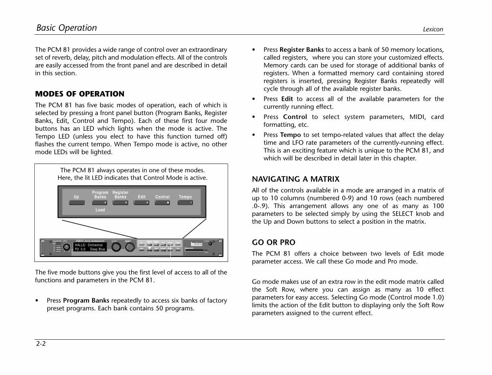
The PCM 81 provides a wide range of control over an extraordinaryset of reverb, delay, pitch and modulation effects. All of the controlsare easily accessed from the front panel and are described in detailin this section.
MODES OF OPERATIONThe PCM 81 has five basic modes of operation, each of which isselected by pressing a front panel button (Program Banks, RegisterBanks, Edit, Control and Tempo). Each of these first four modebuttons has an LED which lights when the mode is active. TheTempo LED (unless you elect to have this function turned off)flashes the current tempo. When Tempo mode is active, no othermode LEDs will be lighted.
• Press Register Banks to access a bank of 50 memory locations,called registers, where you can store your customized effects.Memory cards can be used for storage of additional banks ofregisters. When a formatted memory card containing storedregisters is inserted, pressing Register Banks repeatedly willcycle through all of the available register banks.
• Press Edit to access all of the available parameters for thecurrently running effect.
• Press Control to select system parameters, MIDI, cardformatting, etc.
• Press Tempo to set tempo-related values that affect the delaytime and LFO rate parameters of the currently-running effect.This is an exciting feature which is unique to the PCM 81, andwhich will be described in detail later in this chapter.
NAVIGATING A MATRIXAll of the controls available in a mode are arranged in a matrix ofup to 10 columns (numbered 0-9) and 10 rows (each numbered.0-.9). This arrangement allows any one of as many as 100parameters to be selected simply by using the SELECT knob andthe Up and Down buttons to select a position in the matrix.
GO OR PROThe PCM 81 offers a choice between two levels of Edit modeparameter access. We call these Go mode and Pro mode.
Go mode makes use of an extra row in the edit mode matrix calledthe Soft Row, where you can assign as many as 10 effectparameters for easy access. Selecting Go mode (Control mode 1.0)limits the action of the Edit button to displaying only the Soft Rowparameters assigned to the current effect.
The PCM 81 always operates in one of these modes.Here, the lit LED indicates that Control Mode is active.
The five mode buttons give you the first level of access to all of thefunctions and parameters in the PCM 81.
• Press Program Banks repeatedly to access six banks of factorypreset programs. Each bank contains 50 programs.
2-3
Basic OperationPCM 81
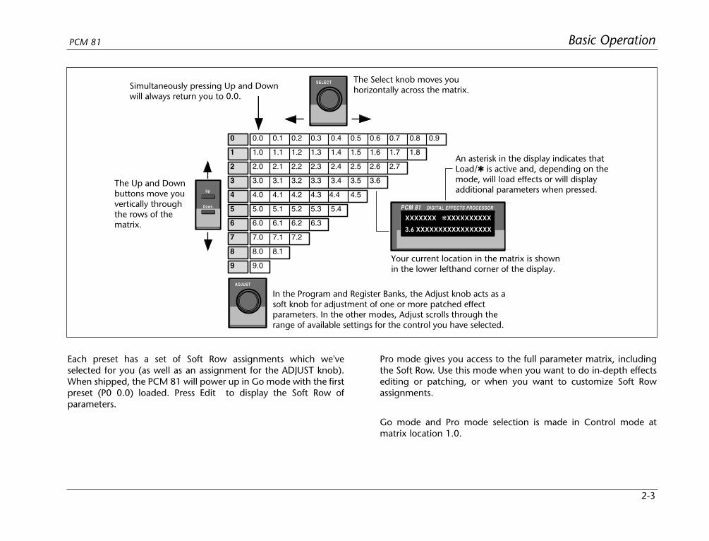
Each preset has a set of Soft Row assignments which we'veselected for you (as well as an assignment for the ADJUST knob).When shipped, the PCM 81 will power up in Go mode with the firstpreset (P0 0.0) loaded. Press Edit to display the Soft Row ofparameters.
Pro mode gives you access to the full parameter matrix, includingthe Soft Row. Use this mode when you want to do in-depth effectsediting or patching, or when you want to customize Soft Rowassignments.
Go mode and Pro mode selection is made in Control mode atmatrix location 1.0.
0 0.0 0.1 0.2 0.3 0.4 0.5 0.6 0.7 0.8 0.9
1 1.0 1.1 1.2 1.3 1.4 1.5 1.6 1.7 1.8
2 2.0 2.1 2.2 2.3 2.4 2.5 2.6 2.7
3 3.0 3.1 3.2 3.3 3.4 3.5 3.6
4 4.0 4.1 4.2 4.3 4.4 4.5
5 5.0 5.1 5.2 5.3 5.4
6 6.0 6.1 6.2 6.3
7 7.0 7.1 7.2
8 8.0 8.1
9 9.0
SELECT
Up
Down
ADJUST
DIGITAL EFFECTS PROCESSORPCM 81
XXXXXXX XXXXXXXXXX
3.6 XXXXXXXXXXXXXXXXX
The Select knob moves youhorizontally across the matrix.
The Up and Downbuttons move youvertically throughthe rows of thematrix.
In the Program and Register Banks, the Adjust knob acts as asoft knob for adjustment of one or more patched effectparameters. In the other modes, Adjust scrolls through the range of available settings for the control you have selected.
An asterisk in the display indicates thatLoad/ is active and, depending on themode, will load effects or will displayadditional parameters when pressed.
Your current location in the matrix is shownin the lower lefthand corner of the display.
Simultaneously pressing Up and Down will always return you to 0.0.
2-4
Basic Operation Lexicon
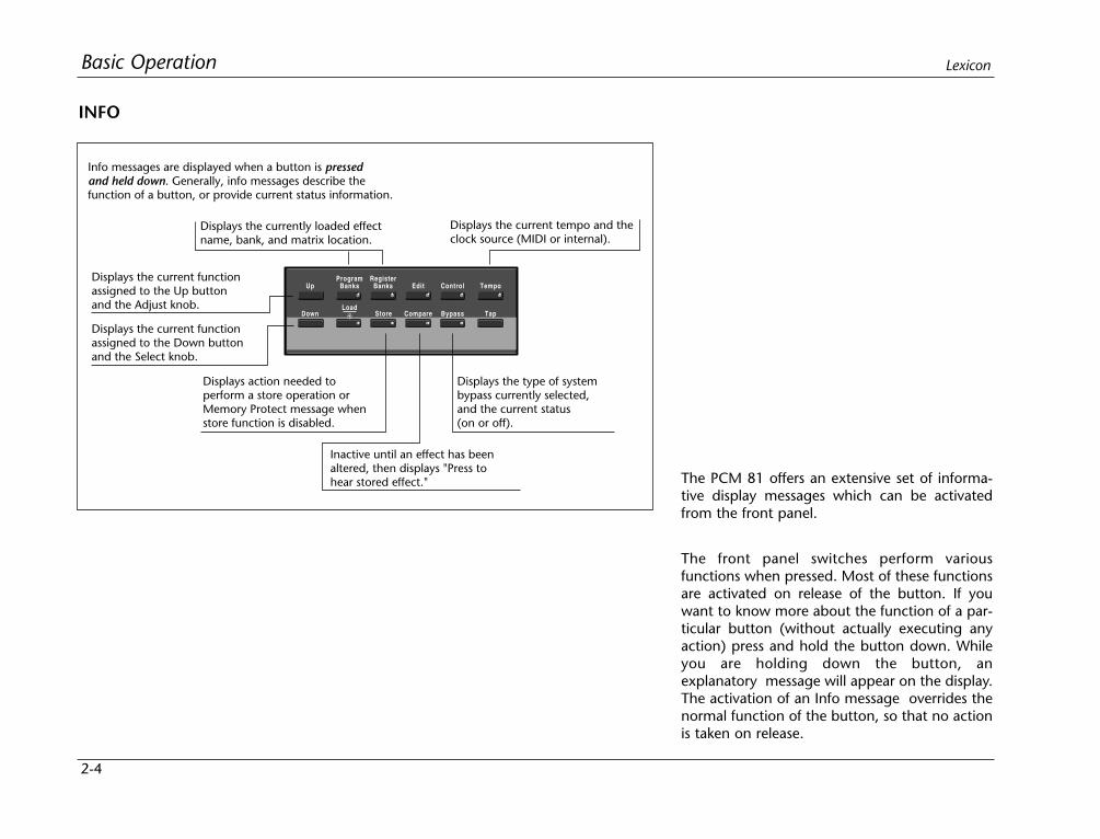
The PCM 81 offers an extensive set of informa-tive display messages which can be activatedfrom the front panel.
The front panel switches perform variousfunctions when pressed. Most of these functionsare activated on release of the button. If youwant to know more about the function of a par-ticular button (without actually executing anyaction) press and hold the button down. Whileyou are holding down the button, anexplanatory message will appear on the display.The activation of an Info message overrides thenormal function of the button, so that no actionis taken on release.
INFO
UpProgram
BanksRegister
Banks Edit Control Tempo
DownLoad
Compare Bypass Tap Store
Displays the currently loaded effectname, bank, and matrix location.
Displays the current tempo and theclock source (MIDI or internal).
Displays the type of systembypass currently selected, and the current status(on or off).
Inactive until an effect has beenaltered, then displays "Press tohear stored effect."
Displays action needed toperform a store operation orMemory Protect message whenstore function is disabled.
Displays the current functionassigned to the Down buttonand the Select knob.
Displays the current functionassigned to the Up buttonand the Adjust knob.
Info messages are displayed when a button is pressedand held down. Generally, info messages describe thefunction of a button, or provide current status information.
2-5
Basic OperationPCM 81
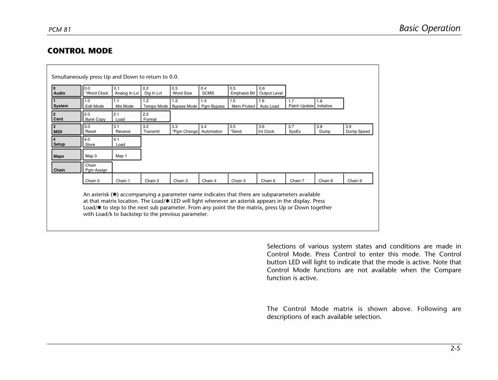
Selections of various system states and conditions are made inControl Mode. Press Control to enter this mode. The Controlbutton LED will light to indicate that the mode is active. Note thatControl Mode functions are not available when the Comparefunction is active.
The Control Mode matrix is shown above. Following aredescriptions of each available selection.
2 2.0 2.1 2.2
3 3.0 3.1 3.2 3.3 3.4
4 4.0 4.1
0 0.0 0.1 0.2 0.3 0.4 0.5 0.6
1.5 1.61 1.0 1.1 1.2 1.3 1.4
Audio *Word Clock
1.7 1.8
3.5 3.6 3.7 3.8 3.9
System
Card
MIDI
Chain
Mapx
Setup
Analog In Lvl Dig In Lvl Word Size SCMS Emphasis Bit Output Level
Edit Mode Mix Mode Tempo Mode Bypass Mode Pgm Bypass Mem Protect Auto Load Patch Update Initialize
Bank Copy Load Format
Reset Receive Transmit *Pgm Change Automation *Send Int Clock SysEx Dump Dump Speed
Map 0 Map 1
ChainPgm Assign
Chain 0 Chain 1 Chain 2 Chain 3 Chain 4 Chain 5 Chain 6 Chain 7 Chain 8 Chain 9
Store Load
Simultaneously press Up and Down to return to 0.0.
An asterisk () accompanying a parameter name indicates that there are subparameters availableat that matrix location. The Load/ LED will light whenever an asterisk appears in the display. PressLoad/ to step to the next sub parameter. From any point the the matrix, press Up or Down togetherwith Load/k to backstep to the previous parameter.
CONTROL MODE

2-6
Basic Operation Lexicon
ROW 0 AUDIO
0.0 Word ClockThe PCM 81 can use its own internal clock as a timing reference,or it can reference an external clock source from the rear panelS/PDIF or AES jacks. Use ADJUST to select Ext XLR (AES), Ext Coax(S/PDIF), Int: 48kHz or Int: 44.1kHz. When either Internal rate isselected, the digital input is disabled. To process audio from thedigital input, you must select Ext.
When External clock is selected, and the PCM 81 detects validdigital audio, the rate of the External word clock will be displayedwith a label indicating the digital audio format type: Prf(Professional [AES]) or Cns (Consumer [S/PDIF]).
The following types of errors are detected when the PCM 81 is setto Ext:
• No Lock: The PCM 81, at some point, lost lock to theincoming digital audio signal. Digital audioinput is muted.
• Out of Range: The sampling rate of the incoming audiosignal is outside of acceptable tolerance limitsof +4%. Digital audio input is muted.
• Non Audio: Indicates transmission of non-audio data, suchas from a CD ROM. Digital audio input ismuted.
Dig In Status
Pressing Load/ from Word Clock will display the current digitalinput status. This status display is continuously updated, acting asa real-time monitor of the PCM 81 digital input. This display isactive even when the PCM 81 is set to Internal clock. Note that inthe case of an AES Pro format signal, "Emp:Yes" means either CCITTor 50/15µs emphasis.
If valid digital audio is detected, the display will show the externalclock rate and format information, along with the status of theEmphasis bit(s) in the incoming audio signal. If the PCM 81 has lostlock, the display message will indicate "No Lock" andparenthetically show the internal clock rate now in use.
0 0.0 0.1 0.2 0.3 0.4
0.5 0.6Audio *Word Clock Analog In Lvl Dig In Lvl Word Size SCMS
Emphasis Bit Output Level
When the PCM 81 is receiving valid digital audio, selecting Word Clock willdisplay the audio format and the rate of the incoming signal.
When the PCM 81 loses lock, it will mute the digital input and switch to Internal Clock.
When External clock is selected, any loss of lock detected in theincoming digital audio, or reception of non-audio data will causethe PCM 81 to immediately mute the digital input, and switch toInternal clock at the sample rate of the last valid external signal. Anerror message will be displayed if this occurs. The PCM 81 willcontinuously try to re-establish lock, returning automatically toExternal clock if and when lock is confirmed.
Audio Word Clock
0.0 Ext:XLR Prf 48
Audio Word Clock
0.0 Ext:Coax Cns 44.1
Audio Dig In Status
0.0 Prf 44.1 Emp:Yes
Audio Dig In Status
0.0 No Lock (Int:44.1)
2-7
Basic OperationPCM 81
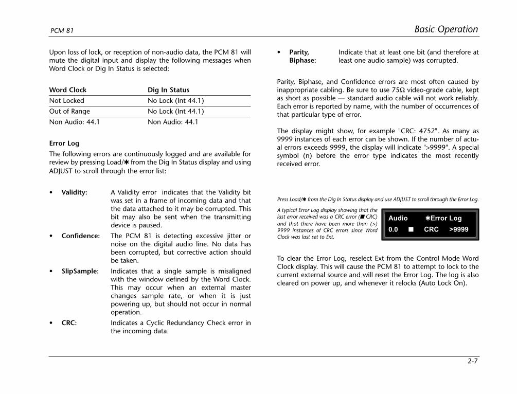
Upon loss of lock, or reception of non-audio data, the PCM 81 willmute the digital input and display the following messages whenWord Clock or Dig In Status is selected:
Word Clock Dig In Status
Not Locked No Lock (Int 44.1)
Out of Range No Lock (Int 44.1)
Non Audio: 44.1 Non Audio: 44.1
Error Log
The following errors are continuously logged and are available forreview by pressing Load/ from the Dig In Status display and usingADJUST to scroll through the error list:
• Validity: A Validity error indicates that the Validity bitwas set in a frame of incoming data and thatthe data attached to it may be corrupted. Thisbit may also be sent when the transmittingdevice is paused.
• Confidence: The PCM 81 is detecting excessive jitter ornoise on the digital audio line. No data hasbeen corrupted, but corrective action shouldbe taken.
• SlipSample: Indicates that a single sample is misalignedwith the window defined by the Word Clock.This may occur when an external masterchanges sample rate, or when it is justpowering up, but should not occur in normaloperation.
• CRC: Indicates a Cyclic Redundancy Check error inthe incoming data.
• Parity, Indicate that at least one bit (and therefore atBiphase: least one audio sample) was corrupted.
Parity, Biphase, and Confidence errors are most often caused byinappropriate cabling. Be sure to use 75Ω video-grade cable, keptas short as possible — standard audio cable will not work reliably.Each error is reported by name, with the number of occurrences ofthat particular type of error.
The display might show, for example "CRC: 4752". As many as9999 instances of each error can be shown. If the number of actu-al errors exceeds 9999, the display will indicate ">9999". A specialsymbol (n) before the error type indicates the most recentlyreceived error.
Audio Error Log
0.0 CRC >9999
Press Load/ from the Dig In Status display and use ADJUST to scroll through the Error Log.
A typical Error Log display showing that thelast error received was a CRC error ( CRC)and that there have been more than (>)9999 instances of CRC errors since WordClock was last set to Ext.
To clear the Error Log, reselect Ext from the Control Mode WordClock display. This will cause the PCM 81 to attempt to lock to thecurrent external source and will reset the Error Log. The log is alsocleared on power up, and whenever it relocks (Auto Lock On).

2-8
Basic Operation Lexicon
0.1 Analog In LvlThis is a master level control for analog left and right inputs. UseADJUST to select values from 0-100%. If using only analog inputs,this should be 100% for best audio performance. Values between0% and 100% are for mixing analog and digital sources.
Note:If the analog signal being fed into the PCM 81 is toohot, turn it down by adjusting the front panel INPUTlevel control, or by changing the rear panel InputGain switch. (See Setting Audio Levels in Chapter 1.)
0.2 Dig In LvlThis is a master level control for the selected digital left and rightinput connector. Use ADJUST to select values from 0-100%. If usingonly digital inputs, this should be 100%, with Analog InLvl set to0% for best audio performance. Values between 0% and 100% arefor mixing analog and digital sources.
Note:Only one digital input connector can be active: XLR(AES/EBU) or Coax (S/PDIF).
If digital audio is interrupted by lock or range errors, or bytransmission of non-audio data, the digital input will be muted.Whenever this occurs, the PCM 81 remains functional, while anerror message, such as those shown at the top of the next column,is displayed.
Any such message will remain on the display until you dismiss it bypressing any front panel button. If the condition causing the erroris corrected, and the digital input is unmuted, the message will stillremain until you dismiss it to ensure that you are informed of acondition that has muted digital audio, even if only for a briefperiod of time. Once the message is dismissed, the display willreturn to its previous state.
Error : Lock
(Press any button)
Error : Out of Range
(Press any button)
Error : Non Audio
(Press any button)
Audio Dig In Lvl
0.2 30% (Muted)
Some errors detected in an incomingdigital audio signal will cause the PCM 81to mute the digital input. When thishappens, the Dig In Lvl display will showboth the level you selected, and the factthat the signal is muted.
If you select the Dig In Lvl parameter while there is a lock, range,or non-audio error, the display will continue to show the level youhave selected, and parenthetically show that the signal has beenmuted.
Note, if Word Clock is set to Int, Dig In Lvl is disabled. You mustselect Ext to process digital audio.

2-9
Basic OperationPCM 81
0.3 WordSizeThe WordSize control allows you to dither the PCM 81 24-bit wordsize to match the device receiving digital audio from the PCM 81.If you are recording to the digital input of a DAT machine, select16 bits. If you have a digital console with a 24-bit bus, select 24bits.
If you are using the analog outputs, select 20 bits (the defaultsetting).
0.4 SCMSDigital audio signals, in order to comply with copyright standards,are encoded with control information which can limit the ability tocopy audio data. This control information is generally known asSCMS (Serial Copy Management System). Under this system, youcan choose to have the audio material processed by the PCM 81encoded to allow one of three levels of copy restriction. To makeyour selection, use ADJUST to select No Copy, One Copy, or MultiCopy.
0.5 Emphasis BitThe Emphasis control allows you to explicitly set the emphasis"flag" in the digital audio, or to pass along the incoming signalwithout changing its emphasis coding. (The PCM 81 does notperform any emphasis or de-emphasis as part of its signalprocessing. The AES input/output path will correctly pass either15/50 or CCITT emphasis.) The choices available with ADJUST are:Yes, No, and Pass Thru.
0.6 Output LevelThis control allows you to select the maximum output level at thePCM 81's analog outputs. Use ADJUST to select +4 dBu, or –10dBu.
Note:Exercise care when switching this control, as a 14dBlevel change instantly occurs when going from -10dBu to +4dBu.
ROW 1 SYSTEM
1.0 Edit ModeThe PCM 81 has been designed with a "plug and play" featurecalled Go mode. In this mode, the most useful parameters of eacheffect are grouped together in a single row which is availablewhenever you press Edit.
Each PCM 81 preset has a set of Go mode parameters which we'veselected for you. When shipped, the PCM 81 will power up in Gomode, with the first preset (P0 0.0) loaded. Press Edit to displaythe first available parameter in the Soft Row.
If you want access to the full parameter matrix for any effect,including the Soft Row parameters, use ADJUST to select Promode. Now, when Edit is pressed, you can select any parameter foradjustment, and customize any effect with your own Soft Rowassignments. For more information about the Soft Row, see Editingan Effect later in this chapter.
1.5 1.6
1 1.0 1.1 1.2 1.3 1.4
1.7 1.8
System Edit Mode Mix Mode Tempo Mode Bypass Mode Pgm Bypass
Mem Protect Auto Load Patch Update Initialize
2-10
Basic Operation Lexicon
1.1 Mix ModeEach PCM 81 effect has its own Mix parameter, with the Mixsetting stored as an integral part of the effect. Mix Mode allowsyou to override these individual Mix settings and set a global Mixvalue for all effects. This is useful when using a mixing console'scontrols to set the amount of wet signal in a mix. In such a case,you can use this control to set all PCM 81 effects to 100% wet.
When shipped, the PCM 81 has the Mix Mode set to Pgm. Thissetting determines that effects will be loaded with their stored Mixsettings, and allows the individual Mix controls in the edit matrixof each effect to be adjusted from 0-100% Wet. To set a global Mixvalue, use ADJUST to select Global, press Load/ to display thecurrent value, and use ADJUST to assign any value from 0-100%Wet.
1.2 Tempo ModeThe PCM 81 gives you an exciting new approach to working withdelay times and modulation parameters. Now you can set theseparameters in beats, allowing you to control your effects in acompletely musical way. Each PCM 81 effect has its own Tempoparameters, with tempo settings stored as an integral part of theeffect. These include: Tempo Rate, Tempo Beat, Tempo Source(internal or MIDI), Tap Duration, and Tap Average. The Globalsetting here allows you to override individual Tempo Rate settingswith a global value which can then be changed on the fly.
When shipped, the PCM 81 has the Tempo Mode set to Pgm, witheach effect driven by its own stored tempo rate. To change to aglobal Tempo Rate, use ADJUST to select Global, press Load/ todisplay the current tempo in BPM (beats per minute), then useADJUST to assign a global tempo value of 40-400BPM.
Whether Tempo Mode is set to Global or Pgm, you can set a newtempo rate by pressing the front panel Tap button twice.Alternatively, you can choose to have tempo set automatically fromincoming MIDI clock. The rate you tap, or the MIDI tempo, will bedisplayed here.
For more information about working with the tempo parameters,see Tempo Mode later in this chapter.
1.3 Bypass Mode/Bypass SrcThis control allows you to determine the behavior of the PCM 81when the front panel Bypass button is pressed. You can also assignan external controller to perform identically to the front panelbutton. When the Bypass button is pressed, the LED will light, anda message indicating bypass type will be displayed. Pressing Bypassagain will turn bypass off.
The choices available via ADJUST are:
• AllMute: Mutes both the input and the output signal,giving complete silence.
• InputMute: Mutes the input to the PCM 81, allowing thetail of the effect to ring out. (This is the defaultsetting.)
• OutputMute: Mutes the output. Audio signals are still beingfed to the PCM 81, so processed audio returnsimmediately when Bypass is turned off.
• Bypass: Completely bypasses the PCM 81, passingunprocessed audio directly through to theoutputs.
2-11
Basic OperationPCM 81
To assign an external controller to perform the selected bypassfunction, press Load/ to display Bypass Src. Use ADJUST to selecta footswitch or any MIDI controller (or Off). Once a source isselected, it will perform the same function assigned to the frontpanel Bypass button.
1.4 Pgm BypassThis control allows you to determine the behavior of the PCM 81when a new effect is loaded. The choices available are: AllMute orBypass.
1.5 Mem ProtectThe PCM 81 provides a memory protection feature to preventaccidental overwriting of your stored effects. When this control isset to On, pressing the front panel Store button will cause an errormessage to be displayed. To enable the Store function, turnADJUST to select Off.
1.6 Auto LoadThis control allows you to choose whether PCM 81 effects will beloaded immediately when selected with SELECT and the Up andDown buttons (On), or whether they will require a press of theLoad/ button (Off).
1.7 Patch UpdateWhen a controller is patched to an effect parameter, this controldetermines when the controller will take control of the parameter.If Immediate is selected, stored parameter values will jump to thecurrent controller position when the effect is loaded. If Delayed isselected, the stored parameter value will remain in effect until thecontroller is moved. See Patching later in this chapter.
1.8 InitializeSelecting this control arms the PCM 81 to revert to its factory set-tings. This will erase all registers and setups, and return thePCM 81 to its default states.
If you press Store, the display will ask "Are you sure?" (Press STORE).If you don't want to reinitialize your unit, press any button to can-cel the operation. If you press Store in response to this message,the display will flash "Restoring original factory settings" and yourunit will be reinitialized.
ROW 2 CARD
2.0 Bank CopyThis control allows you to copy banks of effects from one locationto another. Banks can be copied internally, or to and from PCMCIAMemory Cards. Try, for example, copying Preset Bank 0 into theinternal Register Bank.
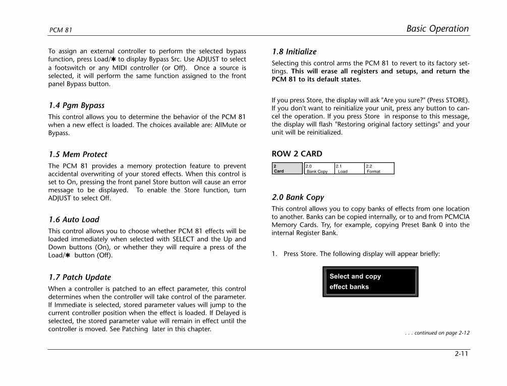
1. Press Store. The following display will appear briefly:
2 2.0 2.1 2.2Card Bank Copy Load Format
Select and copy
effect banks
. . . continued on page 2-12

2-12
Basic Operation Lexicon
2.0 Bank Copy (continued)
The display will then change to show:
2.1 LoadThis control allows you to load audio software from a Memory Cardsimply by inserting the new card and responding to the displayprompts. The PCM 81 can load all PCM 80 algorithm cards. It canalso share registers, maps, and chains with the PCM 80 via RAMcards. (Sharing Setups between the PCM 80 and the PCM 81 is notrecommended.)
2.2 FormatThis control allows you to format a Memory Card for PCM 81 use.Press Store and insert an unformatted card (or one you don't minderasing). Make sure the Write Protect latch on the card is set to Off.Press Store. The display will ask "Are you sure?" (Press STORE). PressStore. The following display will appear briefly:
Card Bank Copy
2.0 Src: P0 Dst: R
Card Bank Copy
2.0 Src: P0 Dst: R
Format and name
memory card
Card Name: N ew Card
(press STORE)
The asterisk indicates that Src is available for adjustment.ADJUST will scroll through all available banks, includinginternal preset and register banks, as well as any banks oninserted PCMCIA cards. Internal banks are labeled "P0...P3"and "R1". Card registers will be labeled "C0, C1, C2" etc.
2. Press Load/ to move the asterisk to Dst.
Now, use ADJUST to select the destination of your copy.Selecting a register bank here will cause its contents to beerased and overwritten with the bank you have selected asthe source when Store is pressed.
4. Press Store to copy the selected source (in this case Preset Bank0) into the internal Register Bank. The display will ask "Are yousure?" (Press STORE). Press any button to cancel. Press Storeto complete the store operation.
The display will then change as shown below:
This display allows you to assign a name (of 10 characters or less)to the card. A blinking cursor indicates that a particular characteris available for changing. Use ADJUST to select the character youwant in that position. Turn SELECT to move the cursor to anothercharacter. Press Store to execute. The display will ask "Are yousure?" (Press STORE). Press Store again to complete the operation.Press any front panel button to cancel.

2-13
Basic OperationPCM 81
ROW 3 MIDI
3.0 ResetThis control resets all patched parameters to their previously storedvalues. When this control is activated, a MIDI "Reset All Controllers"message is also transmitted on the current channel by the PCM 81.
3.1 ReceiveUse ADJUST to select OFF, 1-16, or OMNI for receipt of MIDI mes-sages.
3.2 TransmitUse ADJUST to select OFF or 1-16 for transmission of MIDI messages.
3.3 Pgm ChangeThis control specifies the PCM 81's response to incoming MIDIProgram Change messages. There are four selections available viaADJUST: On, Off, Map and Chain. Pgm+ and Pgm – are availableas subparameters in each location. Pgm+ loads the next highereffect in the current bank, map , or chain. Pgm – loads the nextlower effect. The following sources activate Pgm+ and Pgm –:
OffFootswitch 1Footswitch 2
•••
MIDI Controller #119.
On
Program Change messages 0—49 correspond to PCM 81 Effects0.0 —4.9 in the current bank. Program Change messages 50—127are ignored. The current bank can be changed with MIDI BankSelect Messages as follows:
• 0–5: Program Banks 0–5
• 6: Internal Register Bank
• 7–11: reserved
• 12–58: Memory Card Banks. The number of banksavailable on a given card will vary with its size,as follows:
Card Size # Banks
64 2
256 11
512 23
1 Meg 47
Off
All Program Change and Bank select messages are ignored.
Map
Program Change 0-127 can be mapped to any PCM 81 effect inany internal or card bank. Two 128 element maps are storedinternally, additional maps may be stored on RAM cards. Once youhave selected Map, press Load/ to display:
3 3.0 3.1 3.2 3.3 3.4MIDI Reset Receive Transmit *Pgm Change Automation
3.5 3.6 3.7 3.8 3.9*Send Int Clock SysEx Dump Dump Speed
MIDI Pgm Change
3.3 Map Select 0
Turn ADJUST to select the desired ProgramChange Map.

2-14
Basic Operation Lexicon
Chain
Any Program Change number can be selected to load any one often customized effect “chains". Additional chains can be stored onRAM cards. Once a chain is loaded, effects in the chain are accessedby the controller patched to Pgm + and Pgm – (program incrementand program decrement). Once you have selected Chain, pressLoad/ to display:
Automation sends all MIDI commands in PCM 80 format, which isalso recognized by the PCM 81. As the PCM 80 has only four Banks(0-3), it cannot load programs from PCM 81 Banks 4 and 5 inAutomation mode.
3.5 Send (Foot Pedal, Foot Sw 1, Foot Sw 2, ADJUST)If Transmit is set to On these four controllers can transmit MIDIcontroller messages. Press Load/ to cycle through controllerselections. Use ADJUST to select the MIDI Controller message totransmit.
3.6 Int ClockYou can choose to have the PCM 81 transmit MIDI Clock at thecurrent tempo rate by setting this control to On and Tempo modeSource (0.2) to Internal. If this control is set to Off, MIDI Clock willnot be transmitted.
3.7 SysExThis control is provided for communication with one or moreadditional PCM 81s or computer editor software. On (the defaultsetting) allows SysEx messages to be received by the PCM 81.Press Load/ to select device ID (0-126 ).
3.8 DumpPress Store to configure the PCM 81 to execute MIDI dumps ofsingle effects, banks, maps, chains, or setups. With the exception ofSetup Dumps, all dumps are transmitted in PCM 80 format, whichis also recognized by the PCM 81. You can dump from the frontpanel of either unit to the other. As the PCM 80 has only four Banks(0-3), references to Banks 4 and 5 will be ignored whentransmitted to a PCM 80.
MIDI Pgm Change
3.3 Chain MIDI
MIDI Pgm Change
3.3 Chain 3
Turn ADJUST to select the desired Program Chain. When set toMIDI, Program Chains will be loaded by MIDI Program Changemessages according to the settings of Chain Pgm Assign in Row 6.
To load a specific Program Chain, without sending the PCM 81 aMIDI Program Change message, use ADJUST to display the desiredchain number:
3.4 AutomationThis control is provided for communication with one or moreadditional PCM 80s or PCM 81s. Select On to have values resultingfrom front panel operations sent out as SysEx messages. PressLoad/ to select the ID (0-126 or All) of the target PCM 81(s).
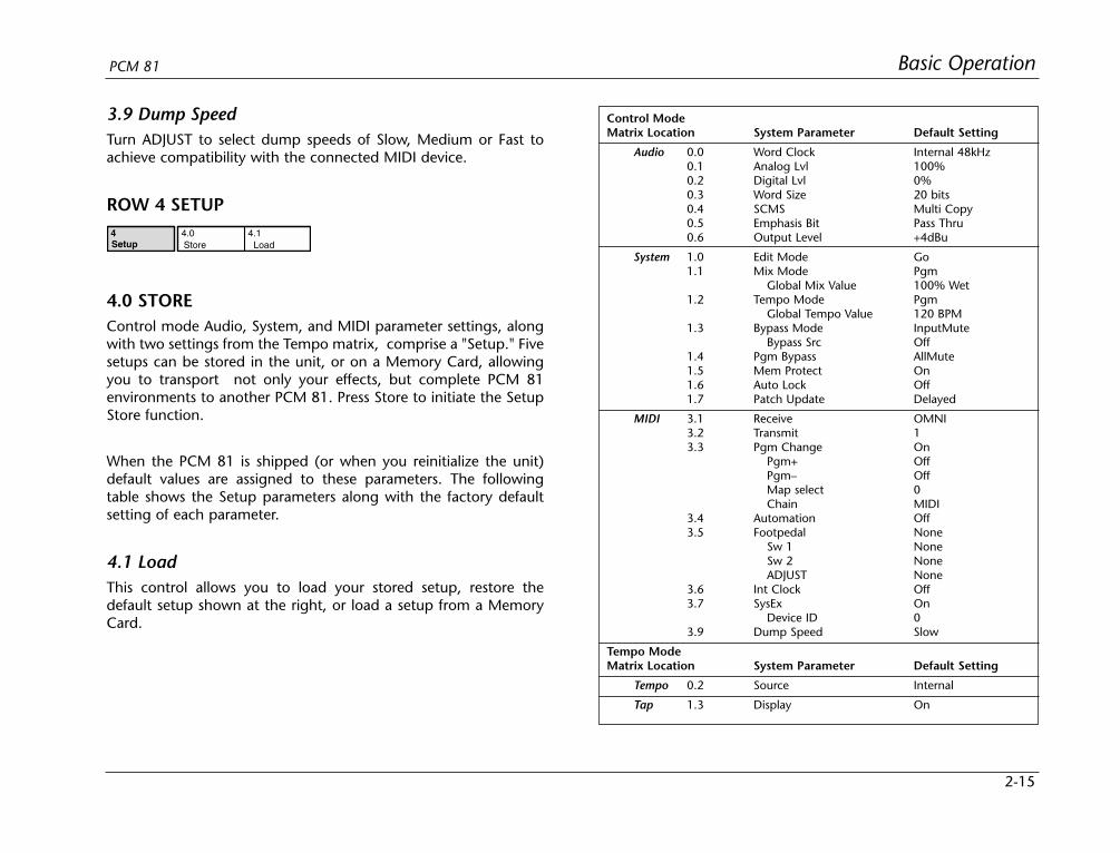
2-15
Basic OperationPCM 81
3.9 Dump SpeedTurn ADJUST to select dump speeds of Slow, Medium or Fast toachieve compatibility with the connected MIDI device.
ROW 4 SETUP
4.0 STOREControl mode Audio, System, and MIDI parameter settings, alongwith two settings from the Tempo matrix, comprise a "Setup." Fivesetups can be stored in the unit, or on a Memory Card, allowingyou to transport not only your effects, but complete PCM 81environments to another PCM 81. Press Store to initiate the SetupStore function.
When the PCM 81 is shipped (or when you reinitialize the unit)default values are assigned to these parameters. The followingtable shows the Setup parameters along with the factory defaultsetting of each parameter.
4.1 LoadThis control allows you to load your stored setup, restore thedefault setup shown at the right, or load a setup from a MemoryCard.
4 4.0 4.1Setup Store Load
Control ModeMatrix Location System Parameter Default Setting
Audio 0.0 Word Clock Internal 48kHz0.1 Analog Lvl 100%0.2 Digital Lvl 0%0.3 Word Size 20 bits0.4 SCMS Multi Copy0.5 Emphasis Bit Pass Thru0.6 Output Level +4dBu
System 1.0 Edit Mode Go1.1 Mix Mode Pgm
Global Mix Value 100% Wet1.2 Tempo Mode Pgm
Global Tempo Value 120 BPM1.3 Bypass Mode InputMute
Bypass Src Off1.4 Pgm Bypass AllMute1.5 Mem Protect On1.6 Auto Lock Off1.7 Patch Update Delayed
MIDI 3.1 Receive OMNI3.2 Transmit 13.3 Pgm Change On
Pgm+ OffPgm– OffMap select 0Chain MIDI
3.4 Automation Off3.5 Footpedal None
Sw 1 NoneSw 2 NoneADJUST None
3.6 Int Clock Off3.7 SysEx On
Device ID 03.9 Dump Speed Slow
Tempo ModeMatrix Location System Parameter Default Setting
Tempo 0.2 Source Internal
Tap 1.3 Display On

2-16
Basic Operation Lexicon
ROW 5 MAPX
Map 0 and Map 1When Control mode 3.3 is set to Map, received MIDI ProgramChange messages will be mapped according to the selectionsmade here. The selections available are: MIDI Program Change #(0-127), Bank # (PCM 81 preset, register, or card bank) and Pgm #(PCM 81 effect number 0-49). When shipped, the PCM 81 has thetwo internal maps configured to access all presets and registers:
Map 0 Map 1
MIDI 0 = P0 0.0 MIDI 0 = P2 2.8
MIDI 127 = P2 2.7 MIDI 121 = R 4.9
ROW 6 CHAIN
The PCM 81 has 10 internal program chains, numbered 0-9. (Tenadditional chains are available if a register card is inserted.) Eachchain is made up of 10 "links" (numbered 0-9). You can assign anyprogram or register to any link in the chain.
A chain can be loaded with a MIDI Program Change message, orby selecting its number directly at Control mode 3.3. Once a chainis loaded, the source assigned to Pgm+ and Pgm– will load the nexthigher or lower program in the chain.
Pgm AssignWhen Control mode 3.3 is set to Chain, received MIDI ProgramChange messages will be mapped according to the selectionsmade here. Two assignments are available: MIDI Program Change# (0-127) and Chain # (0-9). When the PCM 81 is shipped, allprogram numbers are mapped to Chain #0. To changeassignments, set Pgm#, with ADJUST, press Load/ to move the to Chain# and set it with ADJUST. (You cannot assign more thanone chain/MIDI #.)
Mapx Map 0 Map 1
ChainChainPgm Assign
Chain 0 Chain 1 Chain 2 Chain 3 Chain 4
Chain 5 Chain 6 Chain 7 Chain 8 Chain 9
Chain Pgm Assign
Pgm#: 3 Chain#: 3
Chain 3 Prime Blue
Link#: 0 P0 0.0
Chain 0-9Use SELECT to choose a chain. Once a chain is selected, any PCM81 program or register can be assigned to any link in the chain.Press Load/ to move the from Link# to the Bank ID, to theprogram number. Depending on the field marked with the ,ADJUST will select link numbers 0-9, Banks (Pn or Rn), or thedesired program within the displayed bank.

2-17
Basic OperationPCM 81
PROGRAM AND REGISTER BANKSThe PCM 81 has 300 factory-designed programs, organized intosix Program Banks of 50 each, and 50 memory locations, calledregisters, for storing your customized effects. One Register Bank isavailable in the PCM 81 itself. Additional Register Banks can bestored on PCMCIA cards.
SELECTING EFFECTSThe procedure for loading effects is the same, whether you arechoosing from banks of factory presets, or from your own banks ofregisters. When first turned on, the PCM 81 will load whatevereffect was running when it was last turned off. When shipped fromthe factory, the first effect in the first Program Bank (P0 0.0 PrimeBlue) is loaded. The Bank ID (P0, P1, P2, P3, P4, P5 ),matrixlocation, program name, and the algorithm from which the effectis derived are all displayed.
P5 0.0 0.1 0.2 0.3 0.4 0.5 0.6 0.7 0.8 0.9
1.0
2.0
3.0
4.0
P4 0.0 0.1 0.2 0.3 0.4 0.5 0.6 0.7 0.8 0.9
1.0
2.0
3.0
4.0
P3 0.0 0.1 0.2 0.3 0.4 0.5 0.6 0.7 0.8 0.9
1.0
2.0
3.0
4.0
P2 0.0 0.1 0.2 0.3 0.4 0.5 0.6 0.7 0.8 0.9
1.0
2.0
3.0
4.0
P1 0.0 0.1 0.2 0.3 0.4 0.5 0.6 0.7 0.8 0.9
1.0
2.0
3.0
4.0
P0 0.0 0.1 0.2 0.3 0.4 0.5 0.6 0.7 0.8 0.9
1.0 1.1 1.2 1.3 1.4 1.5 1.6 1.7 1.8
2.0 2.1 2.2 2.3 2.4 2.5 2.6 2.7
3.0 3.1 3.2 3.3 3.4 3.5 3.6
4.0 4.1 4.2 4.3 4.4 4.5
1.9
4.6 4.7 4.8 4.9
3.7 3.8 3.9
2.8 2.9
R 0.0 0.1 0.2 0.3 0.4 0.5 0.6 0.7 0.8 0.9
1.0 1.1 1.2 1.3 1.4 1.5 1.6 1.7 1.8
2.0 2.1 2.2 2.3 2.4 2.5 2.6 2.7
3.0 3.1 3.2 3.3 3.4 3.5 3.6
4.0 4.1 4.2 4.3 4.4 4.5
1.9
4.6 4.7 4.8 4.9
3.7 3.8 3.9
2.8 2.9
The PCM 81 has 6 Program Banks, each with50 factory-designed programs.
A Register Bank provides 50 memory locationsfor storing your own effects.All PCM 81 programs have
one or more parameterspatched to the Adjust knob.
In Program Banks or RegisterBanks mode, turn Adjust tochange the sound of thecurrently running effect. WhileAdjust is turned, the patchname and value are displayed.
ADJUST
Indicates that the ADJUST knob is patched to one or more parameters in the currently-running effect - in this case, Prime Blue.
The patch indicator remains to indicate that the currently-running effect has an ADJUSTknob patch, although the displayed effect may not.
An asterisk in the display indicates that the displayed effect is not loaded.
Turn SELECT to display another effect.
Program Bank ID
Matrix Location
Program Name
Chorus+Rvb
P0 0.0 Prime Blue
Algorithm
Chorus+Rvb
P0 0.1 EkoChorus
Press Program Banks to cycle through the program banks.Simultaneously press Program Banks along with either Up or Downto backstep.
Turn SELECT to scroll through all 300 effects. Press Program Banksto reselect the last displayed effect in another bank. Press Load/to load the displayed effect.
In the Program and Register Banks, ADJUST is a Soft Knob. Each ofthe factory-designed programs has one or more parameterspatched to this knob, providing a quick way to make usefulchanges to the effect. For example, in P0 0.0 Prime Blue, ADJUSTvaries the mix of Chorus, Echo and Reverb effects.
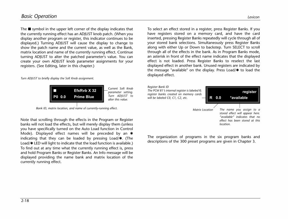
2-18
Basic Operation Lexicon
The symbol in the upper left corner of the display indicates thatthe currently running effect has an ADJUST knob patch. (When youdisplay another program or register, this indicator continues to bedisplayed.) Turning ADJUST will cause the display to change toshow the patch name and the current value, as well as the Bank,matrix location and name of the currently running effect. Continueturning ADJUST to alter the patched parameter's value. You cancreate your own ADJUST knob parameter assignments for yourregisters. (See Editing, later in this chapter.)
To select an effect stored in a register, press Register Banks. If youhave registers stored on a memory card, and have the cardinserted, pressing Register Banks repeatedly will cycle through all ofyour stored bank selections. Simultaneously press Register Banksalong with either Up or Down to backstep. Turn SELECT to scrollthrough all of the effects in the bank. As in Program Banks mode,an asterisk in front of the effect name indicates that the displayedeffect is not loaded. Press Register Banks to reselect the lastdisplayed effect in another bank. Unused registers are indicated bythe message "available" on the display. Press Load/ to load thedisplayed effect.
Turn ADJUST to briefly display the Soft Knob assignment.
Bank ID, matrix location, and name of currently-running effect.
EfxRvb X 32
P0 0.0 Prime Blue
Current Soft Knobparameter setting.Turn ADJUST toalter this value.
Register Bank IDThe PCM 81’s internal register is labeled R;register banks created on memory cardswill be labeled C0, C1, C2, etc.
The name you assign to astored effect will appear here.“available” indicates that noeffect has been stored at thislocation.
Note that scrolling through the effects in the Program or Registerbanks will not load the effects, but will merely display them (unlessyou have specifically turned on the Auto Load function in ControlMode). Displayed effect names will be preceded by an
indicating that they can be loaded by pressing Load/. (TheLoad/ LED will light to indicate that the load function is available.)To find out at any time what the currently running effect is, pressand hold Program Banks or Register Banks. An Info message will bedisplayed providing the name bank and matrix location of thecurrently running effect.
Matrix Location
register
R 0.0 *available
The organization of programs in the six program banks anddescriptions of the 300 preset programs are given in Chapter 3.
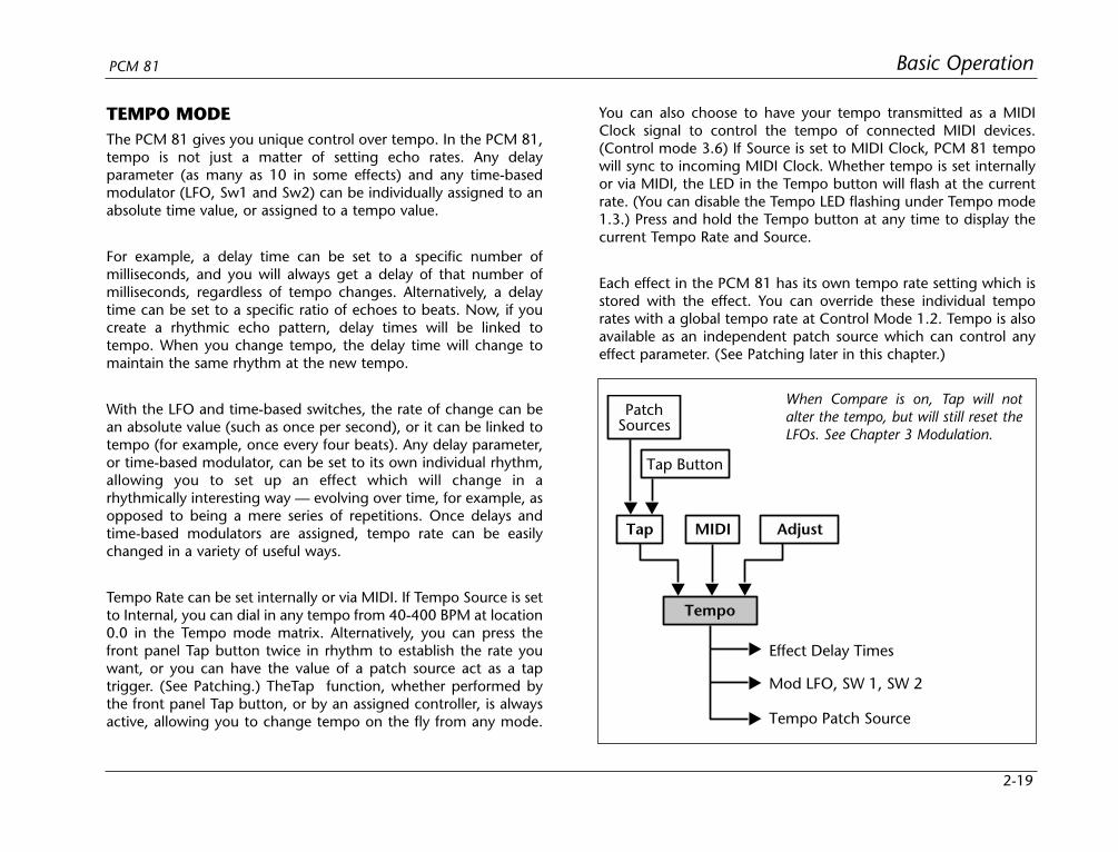
2-19
Basic OperationPCM 81
TEMPO MODEThe PCM 81 gives you unique control over tempo. In the PCM 81,tempo is not just a matter of setting echo rates. Any delayparameter (as many as 10 in some effects) and any time-basedmodulator (LFO, Sw1 and Sw2) can be individually assigned to anabsolute time value, or assigned to a tempo value.
For example, a delay time can be set to a specific number ofmilliseconds, and you will always get a delay of that number ofmilliseconds, regardless of tempo changes. Alternatively, a delaytime can be set to a specific ratio of echoes to beats. Now, if youcreate a rhythmic echo pattern, delay times will be linked totempo. When you change tempo, the delay time will change tomaintain the same rhythm at the new tempo.
With the LFO and time-based switches, the rate of change can bean absolute value (such as once per second), or it can be linked totempo (for example, once every four beats). Any delay parameter,or time-based modulator, can be set to its own individual rhythm,allowing you to set up an effect which will change in arhythmically interesting way — evolving over time, for example, asopposed to being a mere series of repetitions. Once delays andtime-based modulators are assigned, tempo rate can be easilychanged in a variety of useful ways.
Tempo Rate can be set internally or via MIDI. If Tempo Source is setto Internal, you can dial in any tempo from 40-400 BPM at location0.0 in the Tempo mode matrix. Alternatively, you can press thefront panel Tap button twice in rhythm to establish the rate youwant, or you can have the value of a patch source act as a taptrigger. (See Patching.) TheTap function, whether performed bythe front panel Tap button, or by an assigned controller, is alwaysactive, allowing you to change tempo on the fly from any mode.
You can also choose to have your tempo transmitted as a MIDIClock signal to control the tempo of connected MIDI devices.(Control mode 3.6) If Source is set to MIDI Clock, PCM 81 tempowill sync to incoming MIDI Clock. Whether tempo is set internallyor via MIDI, the LED in the Tempo button will flash at the currentrate. (You can disable the Tempo LED flashing under Tempo mode1.3.) Press and hold the Tempo button at any time to display thecurrent Tempo Rate and Source.
Each effect in the PCM 81 has its own tempo rate setting which isstored with the effect. You can override these individual temporates with a global tempo rate at Control Mode 1.2. Tempo is alsoavailable as an independent patch source which can control anyeffect parameter. (See Patching later in this chapter.)
PatchSources
Tap Button
Tap MIDI Adjust
Tempo
Tempo Patch Source
Mod LFO, SW 1, SW 2
Effect Delay Times
When Compare is on, Tap will notalter the tempo, but will still reset theLFOs. See Chapter 3 Modulation.

2-20
Basic Operation Lexicon
THE TEMPO MODE MATRIXPress Tempo to access the following tempo parameters:
example, the rate is 120 BPM, and you select eighth-note here, thetempo will be 120 eighth-notes per minute. If you selectquarter-note here, the tempo will be 120 quarter-notes per minute.(The factory default is quarter-note.)
0.2 SourceYou can choose to have tempo determined by the PCM 81 Tap andRate controls (Internal), or by MIDI Clock. When MIDI Clock isselected as the tempo source, Tap acts as a reset, setting the down-beat of the LFO and the time-based switches.
ROW 1 TAP
1.0 Tap DurationThis control determines how many beats will occur in a tapinterval. The default setting (1 beat) is probably adequate for mostapplications. With the default setting of 1 beat, if the tempo is setto 120 bpm, and the beat value is set to quarter-note, each TAP =1 quarter-note = 1 beat. Available values are: 1/8, 1/7, 1/6, 1/5,1/4, 1/3, 1/2, 1-8 beats
1.1 Tap Source and Tap LevelPress Load/ to toggle between these two controls. Tap Sourceallows you to assign the Tap function to any of the PCM 81’sInternal, MIDI, or MIDI controllers as listed under Patching. TapLevel allows you to set the level at which the Tap function istriggered.
0 0.0 0.1 0.2
1 1.0 1.1 1.2 1.3
Tempo Rate Beat Value Source
Tap Duration *Source Average Display
Simultaneously press Up and Down to return to 0.0.
An asterisk () accompanying a parameter name indicatesthat there are sub parameters available at that matrix location.The Load/ LED will light whenever an asterisk appears in thedisplay. Press Load/ to step to the next sub parameter.
From any point in the matrix, press Up or Down togetherwith Load/ to backstep to the previous parameter
ROW 0 TEMPO
0.0 RateThis is the current tempo (in Beats Per Minute). When 0.2 is set toInternal, turning ADJUST allows you to select a different rate(40-400 BPM). The Tempo LED will flash at the new rate. Note thatfractional tempos can be tapped in, but are not available viaADJUST. The display will always show the nearest whole numbervalue.
0.1 BeatValueTempo is expressed in BPM. This control allows you to specify thevalue of the beat. Eighth, dotted-eighth, quarter, dotted-quarter,half, dotted-half, and whole-note values are available. If, for
0 0.0 0.1 0.2Tempo Rate Beat Value Source
1 1.0 1.1 1.2 1.3Tap Duration *Source Average Display

2-21
Basic OperationPCM 81
1.2 AverageThis control allows you to average the last 2-8 taps. Highernumbers mean that the response to incoming taps will be moregradual. (The tempo is updated on every tap, but with a valuewhich is the average of the last 2-8 taps.) Higher average values aremore useful if you're trying to lock into a pre-recorded track.
1.3 DisplayThis control allows you to disable the flashing of the Tempo LED.Turn ADJUST to select Off. The Tempo LED will turn off.
EDITING AN EFFECTWith 17 algorithms and 300 preset effects, the PCM 81 gives youa lot to play with right out of the box. An enormous range ofediting control is provided for each algorithm, with parametersorganized in an edit matrix of as many as 100 main controls. Inaddition to providing this powerful sound design capability, thePCM 81 is also designed to allow you to customize these controlsfor your day-to-day editing needs, or to simply use a subset ofcontrols specially designed for each preset.
This section will describe three basic levels of editing, from thesimplest "plug and play" method, through the full edit matrix.
THE SOFT KNOBEvery preset in the PCM 81 has one or more of its availableparameters patched to the front panel ADJUST knob. This SoftKnob provides the first level of editing control. Once you haveloaded a preset, simply turn ADJUST to alter the effect.
When shipped, the PCM 81 will power up with the first preset (P00.0 Prime Blue) loaded. The following display will appear:
Indicates that the ADJUST knob is patched to one or more parameters in the currently-running effect. This indicator will stay on even if another effect is selected for display.
Program Bank ID
Matrix Location
Program Name
Chorus+Rvb
P0 0.0 Prime Blue
Algorithm
Turn ADJUST. The display will change to show the name assignedto the ADJUST patch, and the current value of the patch. Continueturning ADJUST to change the value of the patch along its entirerange. The range of ADJUST knob control can be limited in ControlMode, making it possible, for example, to have a range of only0...1, in order to have the ADJUST knob behave as an Off/Oncontrol. Many of the presets have range limits to make them moreconvenient to use. In some of the presets, the changes effected byADJUST will be as simple as altering the wet/dry mix. In others,such as the example shown below, turning ADJUST will glide youall the way from a chorusing effect to a reverb effect over thecomplete control range of 0-127.
The name that has been assigned to the ADJUST knob patch is shown here.
The current value of the patchedparameter(s) appears here. TurnADJUST to alter this value.
Efx/Rvb X :33
P0 0.0 Prime Blue

2-22
Basic Operation Lexicon
Details on how to create your own ADJUST knob patches are givenat the end of this chapter under Patching.
Beyond simple ADJUST knob editing, the PCM 81 offers two levelsof editing control, called Go mode and Pro mode. Go mode isdesigned to be a basic "plug and play" mode, with easy access toa specific set of preset parameters. For each of the 300 presets, wehave designed a Soft Row containing those parameters whichallow you to make value changes to the effect without losing thecharacter of the sound.
Controlling the Soft Knob with a Foot PedalIf you have a foot pedal connected to the PCM rear panel FootController jack, you can use it to control the soft knob patch. (Notethat no MIDI connections are required to do this.)
To assign a foot pedal control over the soft knob patches, set bothControl mode 3.5 ADJUST and Control mode 3.5 Foot Pedal to thesame MIDI Controller. See Chapter 5 MIDI Operation.
THE SOFT ROWWhen shipped, the PCM 81 will power up in Go mode with the firstpreset (P0 0.0 Prime Blue) loaded. Press Edit to display the SoftRow of parameters which have been designed for this preset. In theexample on the next page, 10 soft row parameters have beenassigned. The name of each Soft Row parameter is displayed, alongwith a reference to its row in the Edit matrix.
Turn SELECT to scroll all of the available parameters in the Soft Row.Turn ADJUST to change the value of any displayed parameter alongits entire range.
Compare
Compare
Compare is on
stored effect active
The Compare light is offuntil you make changesto an effect.
As soon as you alter aneffect, the Compare lightwill go on.
If you press Compare while the lightis on, a message will be displayed . . .
. . . and you will hear the original (stored)version of the effect. You can display theparameter values of the stored effect withSelect and Up and Down.
The Compare light will flash until you press Compare again to reload the edited version ofthe effect. While Compare is on, you cannot select another effect.
COMPAREWhenever you edit a PCM 81 effect from the front panel, the LEDin the Compare button will light. This lets you know that the effecthas been altered since the last store operation, and that the editcompare function is active. Whenever this light is on, you can pressCompare to hear the original version of the effect. A message willbe displayed to inform you that the stored version of the effect isbeing loaded. Although this message is only displayed briefly, theCompare LED will flash to let you know the effect you are hearingis the stored version. While Compare is on, you can use theSELECT knob and the Up and Down buttons to view parametervalues in the stored effect.
Press Compare again to reload your edited version. Anothermessage will be displayed, and the Compare LED will stop flashingand remain lit until you store your edited version, or select and loadanother effect. Altering parameter values with patched sourcesother than ADJUST will not light the LED.

2-23
Basic OperationPCM 81
Each preset has a Soft Row of parameters which have been specifically selected to provideeverything you need to play with the effect. This example shows the Soft Row for P0 0.0 Prime Blue.An asterisk in front of a displayed parameter indicates additional parameters are available whenyou press Load/.
Soft Row parameters are derived from the full Edit matrix (with the exception of the Patch row).In the presets, they are arranged according to their numerical order in the matrix.
ADJUST
Turn Adjust to changethe value of a displayed
parameter.
DIGITAL EFFECTS PROCESSORPCM 81
The Soft Row Display
Edit MatrixRow Label
ParameterName
CurrentParameter Value
Controls High Cut
12.50 kHz
SELECT
Turn Select to movehorizontally across
the Soft Row.
The symbol in theupper left corner of
the display indicatesthat a modulator
is patched as a "source" controller.
The symbol in theupper right corner ofthe display indicatesthat a parameteris a patch "destination."
2 2.1 2.2 2.3 2.4 2.5
3 3.0 3.1 3.2 3.3 3.4
4 4.0 4.1 4.2 4.3 4.4
5 5.1 5.2 5.3 5.4
6 6.0 6.1 6.2 6.3 6.4
7 7.0 7.1 7.2 7.3 7.4 7.5 7.6
8 8.1 8.2 8.3 8.4 8.6
0 0.1 0.2 0.4
1.51 1.0 1.2
Controls
3.5 3.6
4.5 4.6
5.5 5.6
6.5 6.6
Rvb Time
Rvb Design
FX Adjust *InLvl/Pan FX Mix
Low Rt Crossover *Ref Lvl/Dly
Diffusion Attack Spin Link Rvb Out
Patches Patch 5 Patch 6 Patch 7 Patch 8 Patch 9Patch 4Patch 3Patch 2Patch 1Patch 0
Modulation Mod:AR Env Mod:Env L Mod:Env R Mod:Latch Mod:Sw 2
Feedback
Panning
Master Voice 1 Voice 2 Voice 3 Voice 4
Master Voice 1 Voice 2 Voice 3 Voice 4
Voice 5 Voice 6
Voice 5 Voice 6
1.6EkoFbk/Dly
Levels Master Voice 1 Voice 2 Voice 3 Voice 4 Voice 5 Voice 6
Delay Time *Master Voice 1 Voice 2 Voice 3 Voice 4 Voice 5 Voice 6
Chorus *Voice 1 *Voice 2 *Voice 3 *Voice 4 *Voice 5 *Voice 6
0.6*ADJUST
Controls Controls Controls Rvb Time Rvb Time Rvb Time Rvb Design Chorus Mod: LFO Mod: Sw 1Pre Delay Size *Mst Depth *Rate *RateRt HCMid RtFX WidthHigh CutMix
0.0Mix
0.3High Cut
0.5FX Width
1.1Mid Rt
1.3 1.4Rt HC Pre Delay
2.0Size
5.0*Master
8.0Mod:LFO
8.5Mod:Sw 1
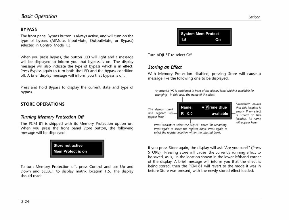
2-24
Basic Operation Lexicon
BYPASSThe front panel Bypass button is always active, and will turn on thetype of bypass (AllMute, InputMute, OutputMute, or Bypass)selected in Control Mode 1.3.
When you press Bypass, the button LED will light and a messagewill be displayed to inform you that bypass is on. The displaymessage will also indicate the type of bypass which is in effect.Press Bypass again to turn both the LED and the bypass conditionoff. A brief display message will inform you that bypass is off.
Press and hold Bypass to display the current state and type ofbypass.
STORE OPERATIONS
Turning Memory Protection OffThe PCM 81 is shipped with its Memory Protection option on.When you press the front panel Store button, the followingmessage will be displayed:
Turn ADJUST to select Off.
Storing an EffectWith Memory Protection disabled, pressing Store will cause amessage like the following one to be displayed:
Store not active
Mem Protect is on
System Mem Protect
1.5 On
To turn Memory Protection off, press Control and use Up andDown and SELECT to display matrix location 1.5. The displayshould read:
An asterisk () is positioned in front of the display label which is available forchanging - in this case, the name of the effect.
The default bankand register willappear here.
Press Load/ to select the ADJUST patch for renaming.Press again to select the register bank. Press again toselect the register location within the selected bank.
“available” meansthat this location isempty. If an effectis stored at thislocation, its namewill appear here.
Name: P rime Blue
R 0.0 available
If you press Store again, the display will ask "Are you sure?" (PressSTORE). Pressing Store will cause the currently running effect tobe saved, as is, in the location shown in the lower lefthand cornerof the display. A brief message will inform you that the effect isbeing stored, then the PCM 81 will revert to the mode it was inbefore Store was pressed, with the newly-stored effect loaded.
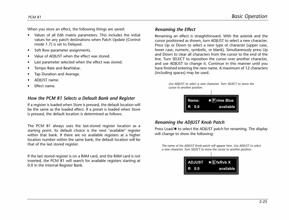
2-25
Basic OperationPCM 81
When you store an effect, the following things are saved:
• Values of all Edit matrix parameters. This includes the initialvalues for any patch destinations when Patch Update (Controlmode 1.7) is set to Delayed.
• Soft Row parameter assignments.
• Value of ADJUST when the effect was stored.
• Last parameter selected when the effect was stored.
• Tempo Rate and BeatValue.
• Tap Duration and Average.
• ADJUST name.
• Effect name.
How the PCM 81 Selects a Default Bank and RegisterIf a register is loaded when Store is pressed, the default location willbe the same as the loaded effect. If a preset is loaded when Storeis pressed, the default location is determined as follows:
The PCM 81 always uses the last-stored register location as astarting point. Its default choice is the next "available" registerwithin that bank. If there are no available registers at a higherlocation number within the same bank, the default location will bethat of the last stored register.
If the last stored register is on a RAM card, and the RAM card is notinserted, the PCM 81 will search for available registers starting at0.0 in the Internal Register Bank.
Renaming the EffectRenaming an effect is straightforward. With the asterisk and thecursor positioned as shown, turn ADJUST to select a new character.Press Up or Down to select a new type of character (upper case,lower case, numeric, symbolic, or blank). Simultaneously press Upand Down to clear all characters from the cursor to the end of theline. Turn SELECT to reposition the cursor over another character,and use ADJUST to change it. Continue in this manner until youhave finished entering the new name. A maximum of 12 characters(including spaces) may be used.
Use ADJUST to select a new character. Turn SELECT to move thecursor to another position.
Name: P rime Blue
R 0.0 available
The name of the ADJUST Knob patch will appear here. Use ADJUST to selecta new character. Turn SELECT to move the cursor to another position.
ADJUST E fxRvb X
R 0.0 available
Renaming the ADJUST Knob PatchPress Load/ to select the ADJUST patch for renaming. The displaywill change to show the following:
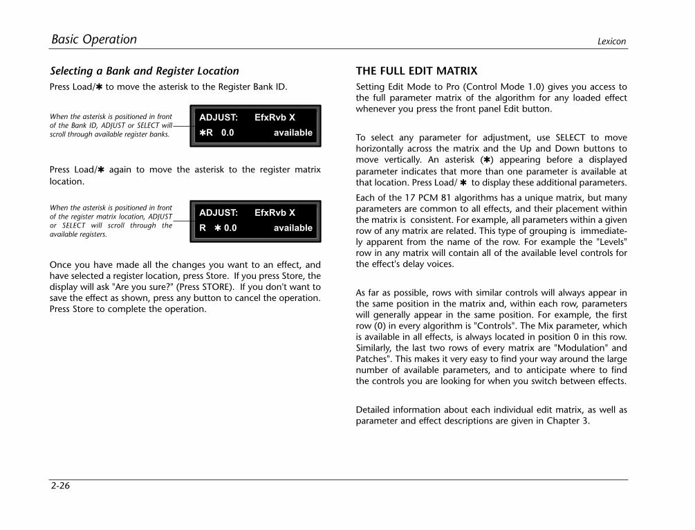
2-26
Basic Operation Lexicon
Selecting a Bank and Register LocationPress Load/ to move the asterisk to the Register Bank ID.
THE FULL EDIT MATRIXSetting Edit Mode to Pro (Control Mode 1.0) gives you access tothe full parameter matrix of the algorithm for any loaded effectwhenever you press the front panel Edit button.
To select any parameter for adjustment, use SELECT to movehorizontally across the matrix and the Up and Down buttons tomove vertically. An asterisk () appearing before a displayedparameter indicates that more than one parameter is available atthat location. Press Load/ to display these additional parameters.
Each of the 17 PCM 81 algorithms has a unique matrix, but manyparameters are common to all effects, and their placement withinthe matrix is consistent. For example, all parameters within a givenrow of any matrix are related. This type of grouping is immediate-ly apparent from the name of the row. For example the "Levels"row in any matrix will contain all of the available level controls forthe effect's delay voices.
As far as possible, rows with similar controls will always appear inthe same position in the matrix and, within each row, parameterswill generally appear in the same position. For example, the firstrow (0) in every algorithm is "Controls". The Mix parameter, whichis available in all effects, is always located in position 0 in this row.Similarly, the last two rows of every matrix are "Modulation" andPatches". This makes it very easy to find your way around the largenumber of available parameters, and to anticipate where to findthe controls you are looking for when you switch between effects.
Detailed information about each individual edit matrix, as well asparameter and effect descriptions are given in Chapter 3.
When the asterisk is positioned in frontof the Bank ID, ADJUST or SELECT willscroll through available register banks.
ADJUST: EfxRvb X
R 0.0 available
When the asterisk is positioned in frontof the register matrix location, ADJUSTor SELECT will scroll through theavailable registers.
ADJUST: EfxRvb X
R 0.0 available
Press Load/ again to move the asterisk to the register matrixlocation.
Once you have made all the changes you want to an effect, andhave selected a register location, press Store. If you press Store, thedisplay will ask "Are you sure?" (Press STORE). If you don't want tosave the effect as shown, press any button to cancel the operation.Press Store to complete the operation.
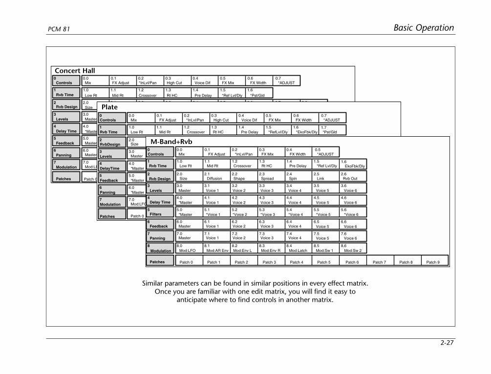
2-27
Basic OperationPCM 81
2 2.0 2.1 2.2 2.3 2.4 2.5 2.6 2.7 2.8
3 3.0 3.1 3.2 3.3 3.4
4 4.0 4.1 4.2 4.3 4.4
5 5.0 5.1 5.2 5.3 5.4
6 6.0 6.1 6.2 6.3 6.4
7 7.0 7.1 7.2 7.3 7.4 7.5 7.6
0 0.0 0.1 0.2 0.3 0.4 0.5 0.6
1.5 1.61 1.0 1.1 1.2 1.3 1.4
Controls Mix
Rvb Time
Rvb Design
Levels
Delay Time
Feedback
Panning
Modulation
Patches
FX Adjust *InLvl/Pan High Cut Voice Dif FX Mix FX Width
Low Rt Mid Rt Crossover Rt HC Pre Delay *Ref Lvl/Dly *Pst/Gld
Size Diffusion Def Depth Spin Chorus Link Rvb Width *Rvb In/Out
Master Voice 1 Voice 2 Voice 3 Voice 4
*Master Voice 1 Voice 2 Voice 3 Voice 4
Master Voice 1 Voice 2 Voice 3 Voice 4
Master Voice 1 Voice 2 Voice 3 Voice 4
Mod:LFO Mod:AR Env Mod:Env L Mod:Env R Mod:Latch Mod:Sw 1 Mod:Sw 2
Patch 5 Patch 6 Patch 7 Patch 8 Patch 9Patch 4Patch 3Patch 2Patch 1Patch 0
0.7*ADJUST
2 2.0 2.1 2.2 2.3 2.4 2.5 2.6
3 3.0 3.1 3.2 3.3 3.4
4 4.0 4.1 4.2 4.3 4.4
5 5.0 5.1 5.2 5.3 5.4
6 6.0 6.1 6.2 6.3 6.4
7 7.0 7.1 7.2 7.3 7.4 7.5 7.6
0 0.0 0.1 0.2 0.3 0.4 0.5 0.6
1.5 1.61 1.0 1.1 1.2 1.3 1.4
Controls Mix
1.7
FX Adjust *InLvl/Pan High Cut Voice Dif FX Mix FX Width
Rvb Time
RvbDesign
Levels
DelayTime
Feedback
Panning
Modulation
Patches
Low Rt Mid Rt Crossover Rt HC Pre Delay *RefLvl/Dly *EkoFbk/Dly *Pst/Gld
Size Diffusion Attack Spin Link Rvb Width *Rvb In/Out
Master Voice 1 Voice 2 Voice 3 Voice 4
*Master Voice 1 Voice 2 Voice 3 Voice 4
*Master Voice 1 Voice 2 Voice 3 Voice 4
*Master Voice 1 Voice 2 Voice 3 Voice 4
Mod:LFO Mod:AR Env Mod:Env L Mod:Env R Mod:Latch Mod:Sw 1 Mod:Sw 2
Patch 0 Patch 1 Patch 2 Patch 3 Patch 4 Patch 5 Patch 6 Patch 7 Patch 8 Patch 9
0.7*ADJUST
2 2.0 2.1 2.2 2.3 2.4 2.5 2.6
3 3.0 3.1 3.2 3.3 3.4
4 4.0 4.1 4.2 4.3 4.4
5 5.0 5.1 5.2 5.3 5.4
6 6.0 6.1 6.2 6.3 6.4
7 7.0 7.1 7.2 7.3 7.4 7.5 7.6
8 8.0 8.1 8.2 8.3 8.4 8.5 8.6
0 0.0 0.1 0.2 0.3 0.4
1.51 1.0 1.1 1.2 1.3 1.4
Controls Mix
3.5 3.6
4.5 4.6
5.5 5.6
6.5 6.6
Rvb Time
Rvb Design
FX Adjust *InLvl/Pan FX Mix FX Width
Low Rt Mid Rt Crossover Rt HC Pre Delay *Ref Lvl/Dly
Size Diffusion Shape Spin Link Rvb Out
Patches Patch 5 Patch 6 Patch 7 Patch 8 Patch 9Patch 4Patch 3Patch 2Patch 1Patch 0
Modulation Mod:LFO Mod:AR Env Mod:Env L Mod:Env R Mod:Latch Mod:Sw 1 Mod:Sw 2
Feedback
Panning
Master Voice 1 Voice 2 Voice 3 Voice 4
Master Voice 1 Voice 2 Voice 3 Voice 4
Voice 5 Voice 6
Voice 5 Voice 6
1.6EkoFbk/Dly
Levels Master Voice 1 Voice 2 Voice 3 Voice 4 Voice 5 Voice 6
Delay Time *Master Voice 1 Voice 2 Voice 3 Voice 4 Voice 5 Voice 6
Filters *Master *Voice 1 *Voice 2 *Voice 3 *Voice 4 *Voice 5 *Voice 6
Spread
0.5*ADJUST
Concert Hall
Plate
M-Band+Rvb
Similar parameters can be found in similar positions in every effect matrix.Once you are familiar with one edit matrix, you will find it easy to
anticipate where to find controls in another matrix.
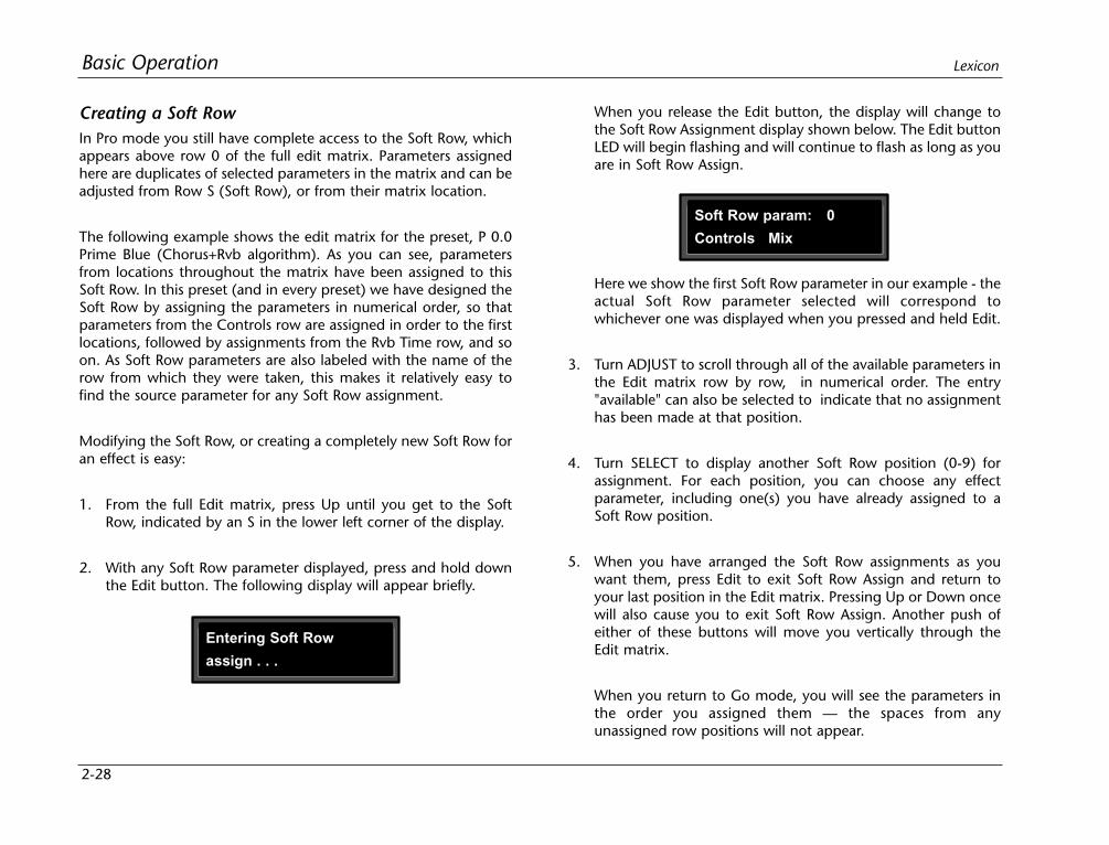
2-28
Basic Operation Lexicon
Creating a Soft RowIn Pro mode you still have complete access to the Soft Row, whichappears above row 0 of the full edit matrix. Parameters assignedhere are duplicates of selected parameters in the matrix and can beadjusted from Row S (Soft Row), or from their matrix location.
The following example shows the edit matrix for the preset, P 0.0Prime Blue (Chorus+Rvb algorithm). As you can see, parametersfrom locations throughout the matrix have been assigned to thisSoft Row. In this preset (and in every preset) we have designed theSoft Row by assigning the parameters in numerical order, so thatparameters from the Controls row are assigned in order to the firstlocations, followed by assignments from the Rvb Time row, and soon. As Soft Row parameters are also labeled with the name of therow from which they were taken, this makes it relatively easy tofind the source parameter for any Soft Row assignment.
Modifying the Soft Row, or creating a completely new Soft Row foran effect is easy:
1. From the full Edit matrix, press Up until you get to the SoftRow, indicated by an S in the lower left corner of the display.
2. With any Soft Row parameter displayed, press and hold downthe Edit button. The following display will appear briefly.
When you release the Edit button, the display will change tothe Soft Row Assignment display shown below. The Edit buttonLED will begin flashing and will continue to flash as long as youare in Soft Row Assign.
Entering Soft Row
assign . . .
Soft Row param: 0
Controls Mix
Here we show the first Soft Row parameter in our example - theactual Soft Row parameter selected will correspond towhichever one was displayed when you pressed and held Edit.
3. Turn ADJUST to scroll through all of the available parameters inthe Edit matrix row by row, in numerical order. The entry"available" can also be selected to indicate that no assignmenthas been made at that position.
4. Turn SELECT to display another Soft Row position (0-9) forassignment. For each position, you can choose any effectparameter, including one(s) you have already assigned to aSoft Row position.
5. When you have arranged the Soft Row assignments as youwant them, press Edit to exit Soft Row Assign and return toyour last position in the Edit matrix. Pressing Up or Down oncewill also cause you to exit Soft Row Assign. Another push ofeither of these buttons will move you vertically through theEdit matrix.
When you return to Go mode, you will see the parameters inthe order you assigned them — the spaces from anyunassigned row positions will not appear.
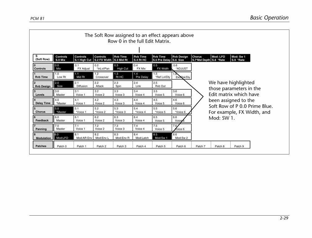
2-29
Basic OperationPCM 81
The Soft Row assigned to an effect appears aboveRow 0 in the full Edit Matrix.
We have highlightedthose parameters in theEdit matrix which havebeen assigned to theSoft Row of P 0.0 Prime Blue.For example, FX Width, andMod: SW 1.
2 2.1 2.2 2.3 2.4 2.5
3 3.0 3.1 3.2 3.3 3.4
4 4.0 4.1 4.2 4.3 4.4
5 5.1 5.2 5.3 5.4
6 6.0 6.1 6.2 6.3 6.4
7 7.0 7.1 7.2 7.3 7.4 7.5 7.6
8 8.1 8.2 8.3 8.4 8.6
0 0.1 0.2 0.4
1.51 1.0 1.2
Controls
3.5 3.6
4.5 4.6
5.5 5.6
6.5 6.6
Rvb Time
Rvb Design
FX Adjust *InLvl/Pan FX Mix
Low Rt Crossover *Ref Lvl/Dly
Diffusion Attack Spin Link Rvb Out
Patches Patch 5 Patch 6 Patch 7 Patch 8 Patch 9Patch 4Patch 3Patch 2Patch 1Patch 0
S(Soft Row)
ControlsS.0 Mix
ControlsS.1 High Cut
ControlsS.2 FX Width
Rvb TimeS.3 Mid Rt
Rvb TimeS.4 Rt HC
Rvb TimeS.5 Pre Delay
Rvb DesignS.6 Size
ChorusS.7*Mst Depth
Mod: LFOS.8 *Rate
Mod: Sw 1S.9 *Rate
Modulation Mod:AR Env Mod:Env L Mod:Env R Mod:Latch Mod:Sw 2
Feedback
Panning
Master Voice 1 Voice 2 Voice 3 Voice 4
Master Voice 1 Voice 2 Voice 3 Voice 4
Voice 5 Voice 6
Voice 5 Voice 6
1.6EkoFbk/Dly
Levels Master Voice 1 Voice 2 Voice 3 Voice 4 Voice 5 Voice 6
Delay Time *Master Voice 1 Voice 2 Voice 3 Voice 4 Voice 5 Voice 6
Chorus *Voice 1 *Voice 2 *Voice 3 *Voice 4 *Voice 5 *Voice 6
0.6*ADJUST
0.0Mix
0.3High Cut
0.5FX Width
1.1Mid Rt
1.3 1.4Rt HC Pre Delay
2.0Size
5.0*Master
8.0Mod:LFO
8.5Mod:Sw 1
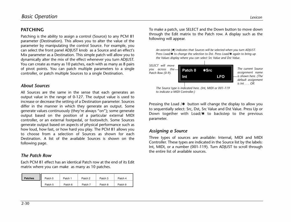
2-30
Basic Operation Lexicon
PATCHINGPatching is the ability to assign a control (Source) to any PCM 81parameter (Destination). This allows you to alter the value of theparameter by manipulating the control Source. For example, youcan select the front panel ADJUST knob as a Source and an effect'sMix parameter as a Destination. This simple patch will allow you todynamically alter the mix of the effect whenever you turn ADJUST.You can create as many as 10 patches, each with as many as 8 pairsof pivot points. You can patch multiple parameters to a singlecontroller, or patch multiple Sources to a single Destination.
About SourcesAll Sources are the same in the sense that each generates anoutput value in the range of 0-127. The output value is used toincrease or decrease the setting of a Destination parameter. Sourcesdiffer in the manner in which they generate an output. Somegenerate values continuously (they’re always “on”); some generateoutput based on the position of a particular external MIDIcontroller, or an external footpedal, or footswitch. Some Sourcesgenerate output based on aspects of physical performance such ashow loud, how fast, or how hard you play. The PCM 81 allows youto choose from a selection of Sources as shown for eachDestination. A list of the available Sources is shown on thefollowing page.
The Patch RowEach PCM 81 effect has an identical Patch row at the end of its Editmatrix where you can make as many as 10 patches.
To make a patch, use SELECT and the Down button to move downthrough the Edit matrix to the Patch row. A display such as thefollowing will appear.
Patch 4Patch 3Patch 2Patch 1Patch 0Patches
Patch 5 Patch 6 Patch 7 Patch 8 Patch 9
An asterisk () indicates that Sources will be selected when you turn ADJUST.Press Load/ to change the selection to Dst. Press Load/ again to bring upthe Values display where you can select Src Value and Dst Value.
SELECT will moveyou across thePatch Row (0-9).
The Source type is indicated here. (Int, MIDI or 001-119to indicate a MIDI Controller.)
The current Sourceassignment nameis shown here. (Thedefault assignmentis Int . . . Off.
Patch 0 Src
Int LFO
Pressing the Load / button will change the display to allow youto sequentially select: Src, Dst, Src Value and Dst Value. Press Up orDown together with Load/ to backstep to the previousparameter.
Assigning a SourceThree types of sources are available: Internal, MIDI and MIDIController. These types are indicated in the Source list by the labels:Int, MIDI, or a number (001-119). Turn ADJUST to scroll throughthe entire list of available sources.
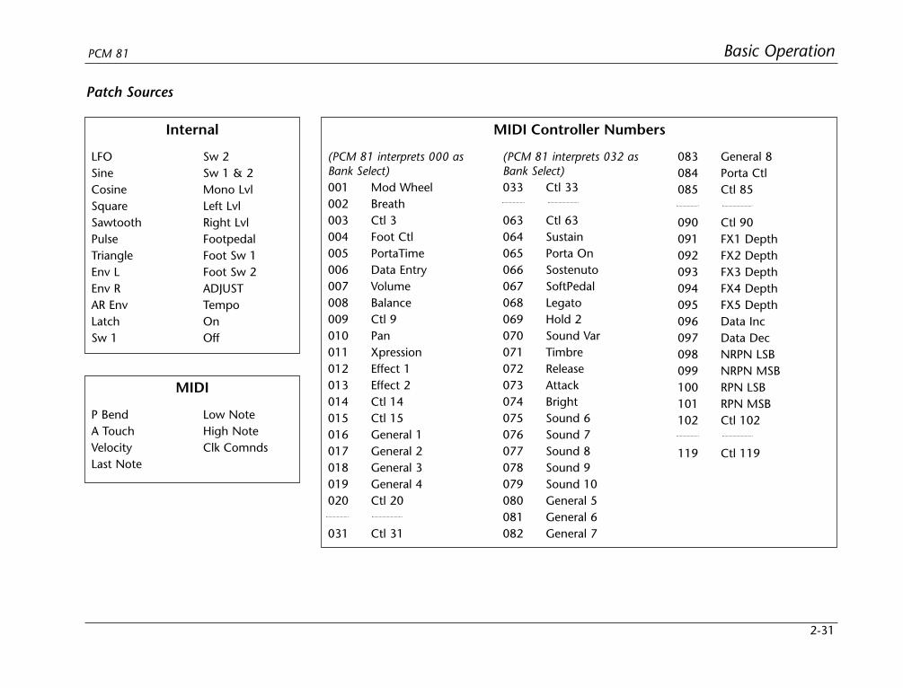
2-31
Basic OperationPCM 81
Patch Sources
LFOSineCosineSquareSawtoothPulseTriangleEnv LEnv RAR EnvLatchSw 1
Sw 2Sw 1 & 2Mono LvlLeft LvlRight LvlFootpedalFoot Sw 1Foot Sw 2ADJUSTTempoOnOff
Internal
(PCM 81 interprets 000 asBank Select)001 Mod Wheel002 Breath003 Ctl 3004 Foot Ctl005 PortaTime006 Data Entry007 Volume008 Balance009 Ctl 9010 Pan011 Xpression012 Effect 1013 Effect 2014 Ctl 14015 Ctl 15016 General 1017 General 2018 General 3019 General 4020 Ctl 20
031 Ctl 31
(PCM 81 interprets 032 asBank Select)033 Ctl 33
063 Ctl 63064 Sustain065 Porta On066 Sostenuto067 SoftPedal068 Legato069 Hold 2070 Sound Var071 Timbre072 Release073 Attack074 Bright075 Sound 6076 Sound 7077 Sound 8078 Sound 9079 Sound 10080 General 5081 General 6082 General 7
083 General 8084 Porta Ctl085 Ctl 85
090 Ctl 90091 FX1 Depth092 FX2 Depth093 FX3 Depth094 FX4 Depth095 FX5 Depth096 Data Inc097 Data Dec098 NRPN LSB099 NRPN MSB100 RPN LSB101 RPN MSB102 Ctl 102
119 Ctl 119
MIDI Controller Numbers
P BendA TouchVelocityLast Note
Low NoteHigh NoteClk Comnds
MIDI

2-32
Basic Operation Lexicon
Assigning a DestinationOnce you have selected a Source, press Load / and the displaywill change to allow you to assign a Destination (Dst).
When Delayed is selected, the stored value of the parameter willcontinue to be in effect until the controller is moved. (It is,therefore, a good idea to set a sensible value to the parameter inthe Edit matrix.)
Mod Row Parameters that Can Be Assigned as PatchDestinations
LFO Rate, Shape, P Width, Depth
AR ENV Attack, Release, Mode
Env L Release
Env R Release
Sw 1 Rate, P Width, Mode
Sw 2 Rate, P Width, Mode
Assigning ValuesOnce you have assigned a Destination, press Load / to get to theValues display.
An asterisk () indicates that Destinations will be selected when you turnADJUST. Press Load/ to bring up the Values display where you can assignSrc Value and Dst Value. Press Load/ again to return to Source selection, etc.
SELECT will moveyou across thePatch Row (0-9).
The Edit matrix row labelfor the currently assignedparameter is shown here.
The name of the current Destinationassignment appears here. (*** Unassigned***will appear across the bottom display line if noassignment is selected.)
Patch 0 Dst
Rvb Time Ref Lvl L
Src values are shown here. The asterisk() indicates that this field is available forcontrol with the ADJUST knob (and thatadditional parameters are available bypressing Load/).
The current Dst value is displayed here.When you press Load/ again, theasterisk will move to indicate that thisvalue is available to be changed byturning ADJUST.
Patch 0 Values
000: Off
Patch 0 Values
000: Off
Turn ADJUST to scroll through all of the parameters in the Editmatrix of the currently loaded effect, including the Modulationparameters.
Once you have assigned a parameter as a Destination, thecontroller you have assigned “owns” that parameter. Adjustmentsmade to this parameter from the Edit matrix, will only affect theinitial value of the parameter when the program is loaded.
The behavior of the parameter on program load is determined bythe setting of the Patch Update parameter in Control mode (1.7).This parameter can be set to Immediate or Delayed.
When Immediate is selected, the initial value of the parametervalue will correspond to the controller position.
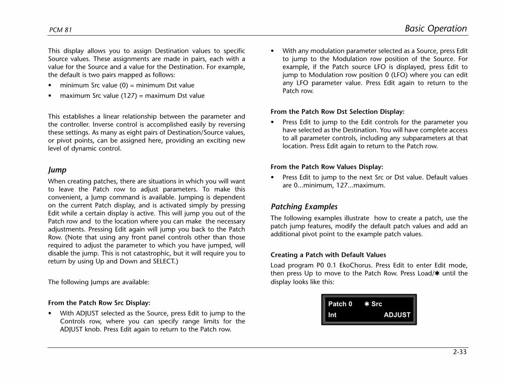
2-33
Basic OperationPCM 81
This display allows you to assign Destination values to specificSource values. These assignments are made in pairs, each with avalue for the Source and a value for the Destination. For example,the default is two pairs mapped as follows:
• minimum Src value (0) = minimum Dst value
• maximum Src value (127) = maximum Dst value
This establishes a linear relationship between the parameter andthe controller. Inverse control is accomplished easily by reversingthese settings. As many as eight pairs of Destination/Source values,or pivot points, can be assigned here, providing an exciting newlevel of dynamic control.
JumpWhen creating patches, there are situations in which you will wantto leave the Patch row to adjust parameters. To make thisconvenient, a Jump command is available. Jumping is dependenton the current Patch display, and is activated simply by pressingEdit while a certain display is active. This will jump you out of thePatch row and to the location where you can make the necessaryadjustments. Pressing Edit again will jump you back to the PatchRow. (Note that using any front panel controls other than thoserequired to adjust the parameter to which you have jumped, willdisable the jump. This is not catastrophic, but it will require you toreturn by using Up and Down and SELECT.)
The following Jumps are available:
From the Patch Row Src Display:
• With ADJUST selected as the Source, press Edit to jump to theControls row, where you can specify range limits for theADJUST knob. Press Edit again to return to the Patch row.
• With any modulation parameter selected as a Source, press Editto jump to the Modulation row position of the Source. Forexample, if the Patch source LFO is displayed, press Edit tojump to Modulation row position 0 (LFO) where you can editany LFO parameter value. Press Edit again to return to thePatch row.
From the Patch Row Dst Selection Display:
• Press Edit to jump to the Edit controls for the parameter youhave selected as the Destination. You will have complete accessto all parameter controls, including any subparameters at thatlocation. Press Edit again to return to the Patch row.
From the Patch Row Values Display:
• Press Edit to jump to the next Src or Dst value. Default valuesare 0...minimum, 127...maximum.
Patching ExamplesThe following examples illustrate how to create a patch, use thepatch jump features, modify the default patch values and add anadditional pivot point to the example patch values.
Creating a Patch with Default Values
Load program P0 0.1 EkoChorus. Press Edit to enter Edit mode,then press Up to move to the Patch Row. Press Load/ until thedisplay looks like this:
Patch 0 Src
Int ADJUST
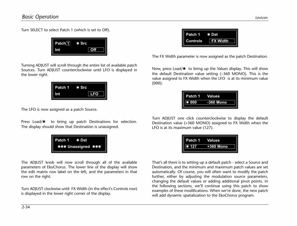
2-34
Basic Operation Lexicon
Turn SELECT to select Patch 1 (which is set to Off).
The FX Width parameter is now assigned as the patch Destination.
Now, press Load/ to bring up the Values display. This will showthe default Destination value setting (–360 MONO). This is thevalue assigned to FX Width when the LFO is at its minimum value(000).
Patch 1 Src
Int Off
Patch 1 Src
Int LFO
Patch 1 Dst
Controls FX Width
Patch 1 Values
000 -360 Mono
Patch 1 Values
127 +360 Mono
Patch 1 Dst
Unassigned
Turning ADJUST will scroll through the entire list of available patchSources. Turn ADJUST counterclockwise until LFO is displayed inthe lower right.
The LFO is now assigned as a patch Source.
Press Load/ to bring up patch Destinations for selection. The display should show that Destination is unassigned.
The ADJUST knob will now scroll through all of the availableparameters of EkoChorus. The lower line of the display will showthe edit matrix row label on the left, and the parameters in thatrow on the right.
Turn ADJUST clockwise until FX Width (in the effect's Controls row)is displayed in the lower right corner of the display.
Turn ADJUST one click counterclockwise to display the defaultDestination value (+360 MONO) assigned to FX Width when theLFO is at its maximum value (127).
That’s all there is to setting up a default patch - select a Source andDestination, and the minimum and maximum patch values are setautomatically. Of course, you will often want to modify the patchfurther, either by adjusting the modulation source parameters,changing the default values or adding additional pivot points. Inthe following sections, we’ll continue using this patch to showexamples of these modifications. When we’re done, the new patchwill add dynamic spatialization to the EkoChorus program.
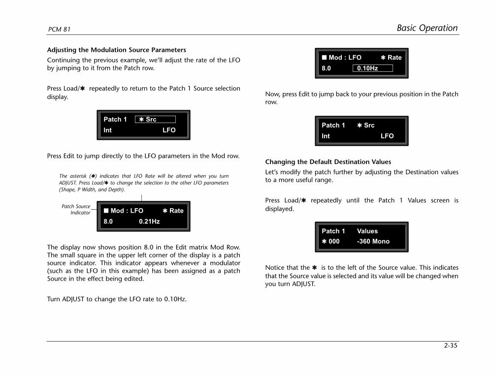
2-35
Basic OperationPCM 81
Adjusting the Modulation Source Parameters
Continuing the previous example, we’ll adjust the rate of the LFOby jumping to it from the Patch row.
Press Load/ repeatedly to return to the Patch 1 Source selectiondisplay. Now, press Edit to jump back to your previous position in the Patch
row.
Patch 1 Src
Int LFO
Press Edit to jump directly to the LFO parameters in the Mod row.
The asterisk () indicates that LFO Rate will be altered when you turnADJUST. Press Load/ to change the selection to the other LFO parameters(Shape, P Width, and Depth).
Patch SourceIndicator Mod : LFO Rate
8.0 0.21Hz
The display now shows position 8.0 in the Edit matrix Mod Row.The small square in the upper left corner of the display is a patchsource indicator. This indicator appears whenever a modulator(such as the LFO in this example) has been assigned as a patchSource in the effect being edited.
Turn ADJUST to change the LFO rate to 0.10Hz.
Mod : LFO Rate
8.0 0.10Hz
Patch 1 Src
Int LFO
Changing the Default Destination Values
Let’s modify the patch further by adjusting the Destination valuesto a more useful range.
Press Load/ repeatedly until the Patch 1 Values screen isdisplayed.
Patch 1 Values
000 -360 Mono
Notice that the is to the left of the Source value. This indicatesthat the Source value is selected and its value will be changed whenyou turn ADJUST.
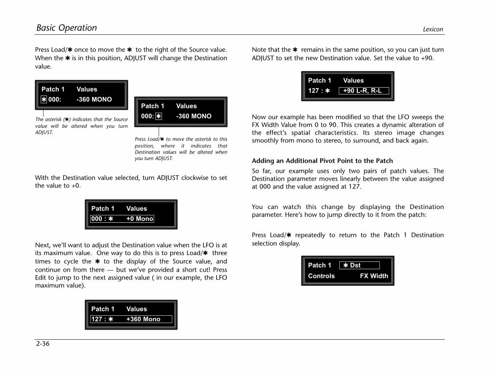
2-36
Basic Operation Lexicon
Press Load/ once to move the to the right of the Source value.When the is in this position, ADJUST will change the Destinationvalue.
Note that the remains in the same position, so you can just turnADJUST to set the new Destination value. Set the value to +90.
Now our example has been modified so that the LFO sweeps theFX Width Value from 0 to 90. This creates a dynamic alteration ofthe effect’s spatial characteristics. Its stereo image changessmoothly from mono to stereo, to surround, and back again.
Adding an Additional Pivot Point to the Patch
So far, our example uses only two pairs of patch values. TheDestination parameter moves linearly between the value assignedat 000 and the value assigned at 127.
You can watch this change by displaying the Destinationparameter. Here’s how to jump directly to it from the patch:
Press Load/ repeatedly to return to the Patch 1 Destinationselection display.
The asterisk () indicates that the Sourcevalue will be altered when you turnADJUST.
Press Load/ to move the asterisk to thisposition, where it indicates thatDestination values will be altered whenyou turn ADJUST.
Patch 1 Values
000: -360 MONOPatch 1 Values
000: -360 MONO
With the Destination value selected, turn ADJUST clockwise to setthe value to +0.
Patch 1 Values
000 : +0 Mono
Patch 1 Values
127 : +360 Mono
Patch 1 Values
127 : +90 L-R, R-L
Next, we’ll want to adjust the Destination value when the LFO is atits maximum value. One way to do this is to press Load/ threetimes to cycle the to the display of the Source value, andcontinue on from there — but we’ve provided a short cut! PressEdit to jump to the next assigned value ( in our example, the LFOmaximum value).
Patch 1 Dst
Controls FX Width

2-37
Basic OperationPCM 81
Press Edit to jump directly to the FX Width parameter in theControls Row.
If the is not at the left of the Source value, press Load/ threetimes to move it there. (You can take a short cut instead —simultaneously press Down and Load/ to back-step.)
Patch 1 Dst
Controls FX Width
Patch Destination Indicator
The FX Width value will bechanging from 0 to 90 andback again.
Controls FX Width
0.5 +0...90 MONO
Patch 1 Values
000 +0 MONO
Patch 1 Values
127 : +90 L-R, R-L
The display will change to show position 0.5 in the Controls Row.Note that the value is changing continuously from 0 to 90 andback again. Notice also the small square in the upper right cornerof the display. This patch destination indicator appears whenever aparameter has been assigned as a patch Destination in the effectbeing edited.
Now let’s return to the Patch row to add a pivot point to the effect.
Press Edit to jump back to the Patch row.
Press Load/ to bring up the Values display. The last value editedwill be displayed, so you will see either the minimum or maximumvalue.
or
Patch 1 Values
000 +0 MONO
Patch 1 Values
127 : +90 L-R, R-Lor
Patch 1 Values
064 : . . . . . . . . . . . . . . .
Patch 1 Values
064 : -45 R, L
Turn ADJUST to display 64. This will be the Source value of our newpivot point. The string of dots in the destination value portion ofthe display indicate that there is no Destination value assignedwhen the source value is 64.
Press Load/ to move the to the right of the Source value, andturn ADJUST clockwise to set the Destination value for this point to–45.

2-38
Basic Operation Lexicon
By adding this pivot point, we have put a “kink” in the patch. Thevalue of the Destination parameter no longer moves in a straightline between 0 and 90. Instead it moves from 0 to –45, and thenfrom –45 to 90. This will produce a very different sounding spatialchange from the original patch. You can see the difference bypressing Load/ twice to display the patch Destination, thenpressing Edit to jump back to the Destination parameter to watchits value change.
Multiple Patches with the Same DestinationIf you create two or more patches with the same Destination, theDestination value will be the sum of all of the patches assigned toit.
For example, if Pedal and ADJUST are both assigned to Mix, theMix value will be the sum of the patch Destination values for thosetwo patches. When creating multiple patches to the sameDestination, you should set the individual Destinations to valueswhich, when added together, are less than or equal to themaximum value for the parameter. Pedal and ADJUST, for example,could each have a maximum value of 50%, or they could beassigned values of 25% and 75%, 60% and 40%, etc.
When the sum of multiple patched parameter Destination values isgreater than the maximum value of the parameter, the parametervalue will remain at maximum until the sum of the patches fallsbelow it.
Mod Row PatchesAR ENV, Latch, Sw 1 and Sw 2 are each activated by assigning athreshold source to T Src that is used to turn them on and off. Thisassignment is a subparameter in the Mod row — not in the Patchrow.
For an example, check out ADJUST and Latch in the preset P0 3.1Rotor Cabinet.
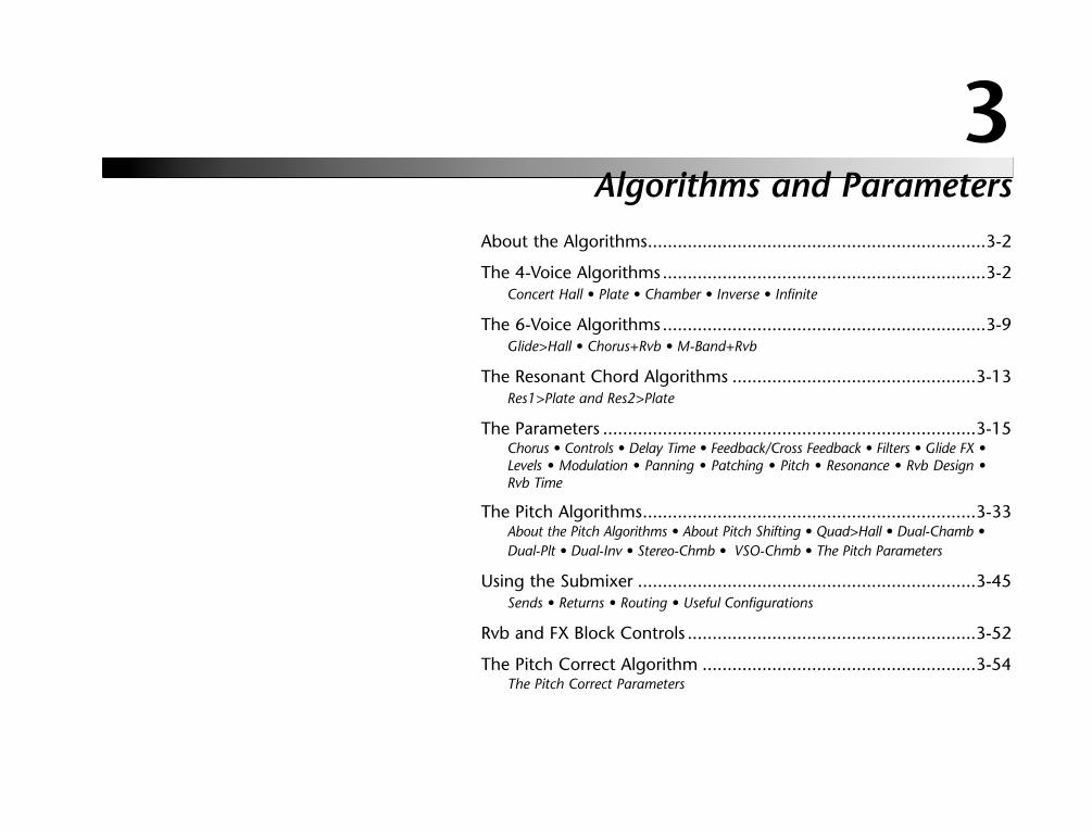
Algorithms and Parameters
3About the Algorithms....................................................................3-2
The 4-Voice Algorithms.................................................................3-2Concert Hall • Plate • Chamber • Inverse • Infinite
The 6-Voice Algorithms.................................................................3-9Glide>Hall • Chorus+Rvb • M-Band+Rvb
The Resonant Chord Algorithms .................................................3-13Res1>Plate and Res2>Plate
The Parameters ...........................................................................3-15Chorus • Controls • Delay Time • Feedback/Cross Feedback • Filters • Glide FX •Levels • Modulation • Panning • Patching • Pitch • Resonance • Rvb Design •Rvb Time
The Pitch Algorithms...................................................................3-33About the Pitch Algorithms • About Pitch Shifting • Quad>Hall • Dual-Chamb •Dual-Plt • Dual-Inv • Stereo-Chmb • VSO-Chmb • The Pitch Parameters
Using the Submixer ....................................................................3-45Sends • Returns • Routing • Useful Configurations
Rvb and FX Block Controls ..........................................................3-52
The Pitch Correct Algorithm .......................................................3-54The Pitch Correct Parameters
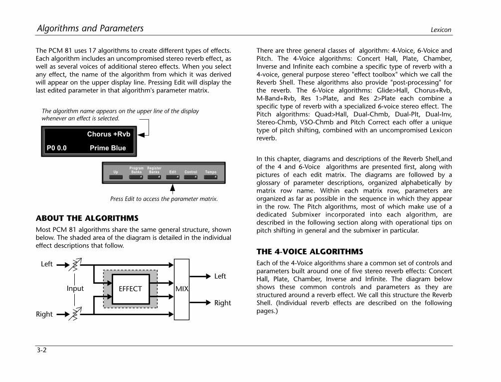
3-2
Algorithms and Parameters Lexicon
The PCM 81 uses 17 algorithms to create different types of effects.Each algorithm includes an uncompromised stereo reverb effect, aswell as several voices of additional stereo effects. When you selectany effect, the name of the algorithm from which it was derivedwill appear on the upper display line. Pressing Edit will display thelast edited parameter in that algorithm's parameter matrix.
There are three general classes of algorithm: 4-Voice, 6-Voice andPitch. The 4-Voice algorithms: Concert Hall, Plate, Chamber,Inverse and Infinite each combine a specific type of reverb with a4-voice, general purpose stereo "effect toolbox" which we call theReverb Shell. These algorithms also provide "post-processing" forthe reverb. The 6-Voice algorithms: Glide>Hall, Chorus+Rvb,M-Band+Rvb, Res 1>Plate, and Res 2>Plate each combine aspecific type of reverb with a specialized 6-voice stereo effect. ThePitch algorithms: Quad>Hall, Dual-Chmb, Dual-Plt, Dual-Inv,Stereo-Chmb, VSO-Chmb and Pitch Correct each offer a uniquetype of pitch shifting, combined with an uncompromised Lexiconreverb.
In this chapter, diagrams and descriptions of the Reverb Shell,andof the 4 and 6-Voice algorithms are presented first, along withpictures of each edit matrix. The diagrams are followed by aglossary of parameter descriptions, organized alphabetically bymatrix row name. Within each matrix row, parameters areorganized as far as possible in the sequence in which they appearin the row. The Pitch algorithms, most of which make use of adedicated Submixer incorporated into each algorithm, aredescribed in the following section along with operational tips onpitch shifting in general and the submixer in particular.
THE 4-VOICE ALGORITHMSEach of the 4-Voice algorithms share a common set of controls andparameters built around one of five stereo reverb effects: ConcertHall, Plate, Chamber, Inverse and Infinite. The diagram belowshows these common controls and parameters as they arestructured around a reverb effect. We call this structure the ReverbShell. (Individual reverb effects are described on the followingpages.)
Chorus +Rvb
P0 0.0 Prime Blue
The algorithm name appears on the upper line of the displaywhenever an effect is selected.
Press Edit to access the parameter matrix.
UpProgram
BanksRegister
Banks Edit Control Tempo
EFFECT MIX
Left
Input
Right
Left
Right
ABOUT THE ALGORITHMSMost PCM 81 algorithms share the same general structure, shownbelow. The shaded area of the diagram is detailed in the individualeffect descriptions that follow.

3-3
Algorithms and ParametersPCM 81
In the 4-Voice algorithms, input levels and pans determine thesignal flow to left and right pairs of delay voices, and also to thereverb effect. Each delay voice has individually adjustable level,delay, feedback, and pan controls, as well as master controls for allof the voices. These algorithms can be used to create a widevariety of stereo delay and modulation effects in parallel with stu-dio quality stereo reverberation.
The two delays after the reverb effect are referred to as post delays.The PstDly Mix control determines how much post delay isactually heard. The Rvb Width control affects only the output of thereverb portion of the effect.
L In
R In
InPan
InPan
REVERB
VoiceDif
V1 Pan
InLvl
InLvl
DelayV1
V2
V1 LvlV1 Fbk
V2 PanV2 LvlV2 Fbk
DelayV3
V4
V3 LvlV3 Fbk
V4 LvlV4 Fbk
V3 Pan
V4 Pan
PstDly
PstDlyPstDly Mix
RvbWidth
FXMix
FXWidth
HiCut
FXAdj
VoiceDif
Rvb In
The delays and the output of the reverb effect are summed at theFX Mix control. This control allows you to blend the relativeamounts of delay and reverb.
FX Width controls the spatial characteristics of the compositereverb and delay effect.
The Hi-Cut parameter provides high end rolloff, while FX Adjustdetermines the output volume of the entire processed signal.
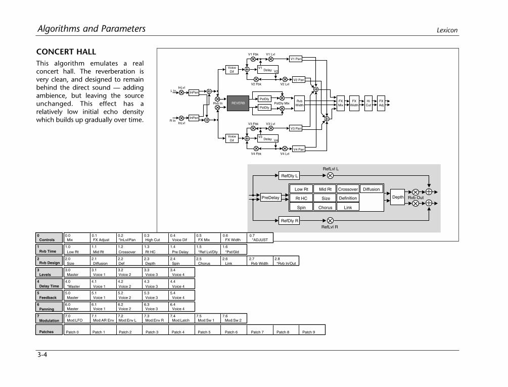
3-4
Algorithms and Parameters Lexicon
CONCERT HALLThis algorithm emulates a realconcert hall. The reverberation isvery clean, and designed to remainbehind the direct sound — addingambience, but leaving the sourceunchanged. This effect has arelatively low initial echo densitywhich builds up gradually over time.
L In
R In
InPan
InPan
REVERB
VoiceDif
V1 Pan
InLvl
InLvl
DelayV1
V2
V1 LvlV1 Fbk
V2 PanV2 LvlV2 Fbk
DelayV3
V4
V3 LvlV3 Fbk
V4 LvlV4 Fbk
V3 Pan
V4 Pan
PstDly
PstDlyPstDly Mix
RvbWidth
FXMix
FXWidth
HiCut
FXAdj
VoiceDif
Rvb In
RefDly L
RefLvl L
RefDly RRefLvl R
Low Rt Mid Rt
Size Depth
Crossover
Rt HC
Spin Chorus Link
Definition
Diffusion
PreDelay Rvb Out
2 2.0 2.1 2.2 2.3 2.4 2.5 2.6 2.7 2.8
3 3.0 3.1 3.2 3.3 3.4
4 4.0 4.1 4.2 4.3 4.4
5 5.0 5.1 5.2 5.3 5.4
6 6.0 6.1 6.2 6.3 6.4
7 7.0 7.1 7.2 7.3 7.4 7.5 7.6
0 0.0 0.1 0.2 0.3 0.4 0.5 0.6
1.5 1.61 1.0 1.1 1.2 1.3 1.4
Controls Mix
Rvb Time
Rvb Design
Levels
Delay Time
Feedback
Panning
Modulation
Patches
FX Adjust *InLvl/Pan High Cut Voice Dif FX Mix FX Width
Low Rt Mid Rt Crossover Rt HC Pre Delay *Ref Lvl/Dly *Pst/Gld
Size Diffusion Def Depth Spin Chorus Link Rvb Width *Rvb In/Out
Master Voice 1 Voice 2 Voice 3 Voice 4
*Master Voice 1 Voice 2 Voice 3 Voice 4
Master Voice 1 Voice 2 Voice 3 Voice 4
Master Voice 1 Voice 2 Voice 3 Voice 4
Mod:LFO Mod:AR Env Mod:Env L Mod:Env R Mod:Latch Mod:Sw 1 Mod:Sw 2
Patch 5 Patch 6 Patch 7 Patch 8 Patch 9Patch 4Patch 3Patch 2Patch 1Patch 0
0.7*ADJUST
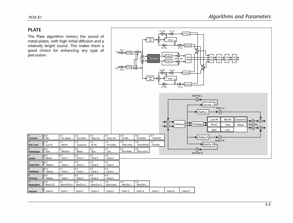
3-5
Algorithms and ParametersPCM 81
PLATEThe Plate algorithm mimics the sound ofmetal plates, with high initial diffusion and arelatively bright sound. This makes them agood choice for enhancing any type ofpercussion.
L In
R In
InPan
InPan
REVERB
VoiceDif
V1 Pan
InLvl
InLvl
DelayV1
V2
V1 LvlV1 Fbk
V2 PanV2 LvlV2 Fbk
DelayV3
V4
V3 LvlV3 Fbk
V4 LvlV4 Fbk
V3 Pan
V4 Pan
PstDly
PstDlyPstDly Mix
RvbWidth
FXMix
FXWidth
HiCut
FXAdj
VoiceDif
Rvb In
PreDelay
RefDly L
EkoFbk L
EkoDly L
RefDly R
EkoDly R
EkoFbk R
Low Rt Mid Rt
Size Attack
Spin Link
Crossover
Rt HC
RefLvl L
RefLvl R
Diffusion Rvb Out
2 2.0 2.1 2.2 2.3 2.4 2.5 2.6
3 3.0 3.1 3.2 3.3 3.4
4 4.0 4.1 4.2 4.3 4.4
5 5.0 5.1 5.2 5.3 5.4
6 6.0 6.1 6.2 6.3 6.4
7 7.0 7.1 7.2 7.3 7.4 7.5 7.6
0 0.0 0.1 0.2 0.3 0.4 0.5 0.6
1.5 1.61 1.0 1.1 1.2 1.3 1.4
Controls Mix
1.7
FX Adjust *InLvl/Pan High Cut Voice Dif FX Mix FX Width
Rvb Time
RvbDesign
Levels
DelayTime
Feedback
Panning
Modulation
Patches
Low Rt Mid Rt Crossover Rt HC Pre Delay *RefLvl/Dly *EkoFbk/Dly *Pst/Gld
Size Diffusion Attack Spin Link Rvb Width *Rvb In/Out
Master Voice 1 Voice 2 Voice 3 Voice 4
*Master Voice 1 Voice 2 Voice 3 Voice 4
*Master Voice 1 Voice 2 Voice 3 Voice 4
*Master Voice 1 Voice 2 Voice 3 Voice 4
Mod:LFO Mod:AR Env Mod:Env L Mod:Env R Mod:Latch Mod:Sw 1 Mod:Sw 2
Patch 0 Patch 1 Patch 2 Patch 3 Patch 4 Patch 5 Patch 6 Patch 7 Patch 8 Patch 9
0.7*ADJUST
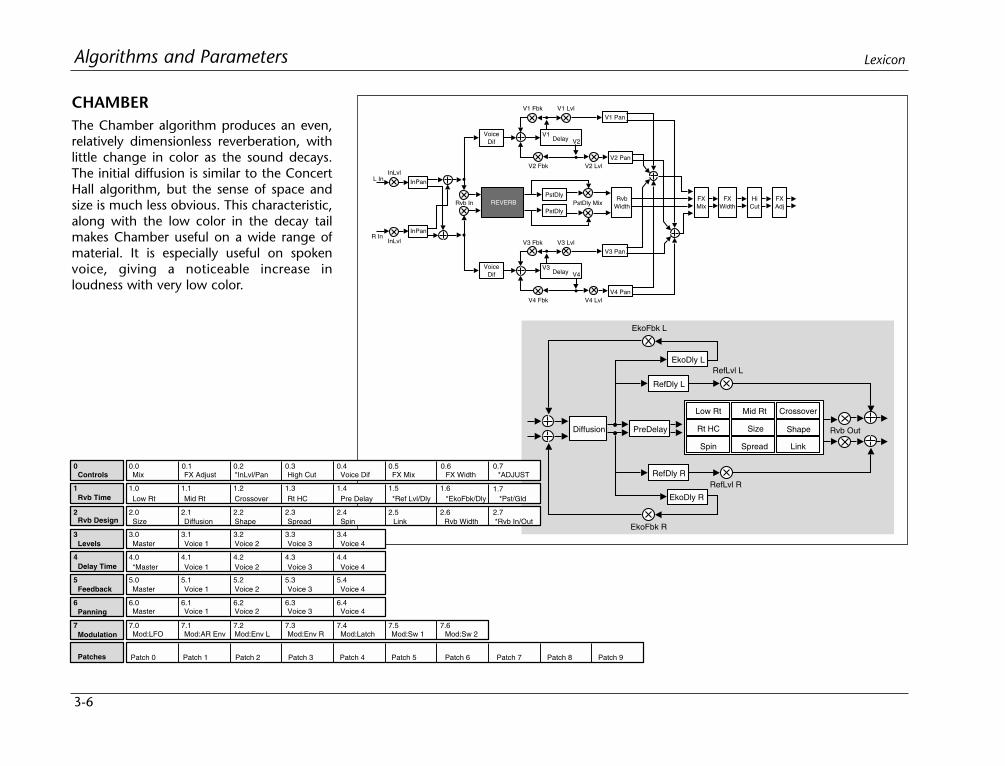
3-6
Algorithms and Parameters Lexicon
CHAMBERThe Chamber algorithm produces an even,relatively dimensionless reverberation, withlittle change in color as the sound decays.The initial diffusion is similar to the ConcertHall algorithm, but the sense of space andsize is much less obvious. This characteristic,along with the low color in the decay tailmakes Chamber useful on a wide range ofmaterial. It is especially useful on spokenvoice, giving a noticeable increase inloudness with very low color.
L In
R In
InPan
InPan
REVERB
VoiceDif
V1 Pan
InLvl
InLvl
DelayV1
V2
V1 LvlV1 Fbk
V2 PanV2 LvlV2 Fbk
DelayV3
V4
V3 LvlV3 Fbk
V4 LvlV4 Fbk
V3 Pan
V4 Pan
PstDly
PstDlyPstDly Mix
RvbWidth
FXMix
FXWidth
HiCut
FXAdj
VoiceDif
Rvb In
PreDelay
RefDly L
EkoFbk L
EkoDly L
RefDly R
EkoDly R
EkoFbk R
Low Rt Mid Rt
Size Shape
Crossover
Rt HC
Spin Spread Link
RefLvl L
RefLvl R
Diffusion Rvb Out
2 2.0 2.1 2.2 2.3 2.4 2.5 2.6 2.7
3 3.0 3.1 3.2 3.3 3.4
4 4.0 4.1 4.2 4.3 4.4
5 5.0 5.1 5.2 5.3 5.4
6 6.0 6.1 6.2 6.3 6.4
7 7.0 7.1 7.2 7.3 7.4 7.5 7.6
0 0.0 0.1 0.2 0.3 0.4 0.5 0.6
1.5 1.61 1.0 1.1 1.2 1.3 1.4
Controls Mix
Rvb Time
Rvb Design
Levels
Delay Time
Feedback
Panning
Modulation
Patches
FX Adjust *InLvl/Pan High Cut Voice Dif FX Mix FX Width
Low Rt Mid Rt Crossover Rt HC Pre Delay *Ref Lvl/Dly
Size Diffusion Shape Spread Spin Link Rvb Width *Rvb In/Out
Master Voice 1 Voice 2 Voice 3 Voice 4
*Master Voice 1 Voice 2 Voice 3 Voice 4
Master Voice 1 Voice 2 Voice 3 Voice 4
Master Voice 1 Voice 2 Voice 3 Voice 4
Mod:LFO Mod:AR Env Mod:Env L Mod:Env R Mod:Latch Mod:Sw 1 Mod:Sw 2
Patch 5 Patch 6 Patch 7 Patch 8 Patch 9Patch 4Patch 3Patch 2Patch 1Patch 0
1.7*EkoFbk/Dly *Pst/Gld
0.7*ADJUST
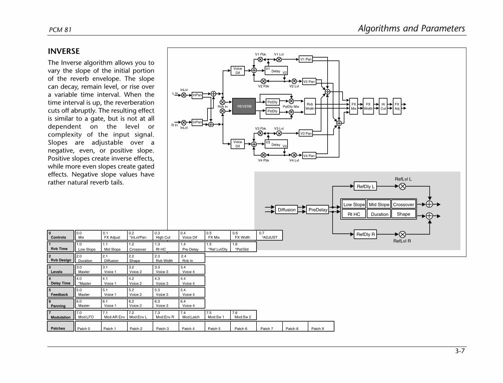
3-7
Algorithms and ParametersPCM 81
INVERSEThe Inverse algorithm allows you tovary the slope of the initial portionof the reverb envelope. The slopecan decay, remain level, or rise overa variable time interval. When thetime interval is up, the reverberationcuts off abruptly. The resulting effectis similar to a gate, but is not at alldependent on the level orcomplexity of the input signal.Slopes are adjustable over anegative, even, or positive slope.Positive slopes create inverse effects,while more even slopes create gatedeffects. Negative slope values haverather natural reverb tails.
L In
R In
InPan
InPan
REVERB
VoiceDif
V1 Pan
InLvl
InLvl
DelayV1
V2
V1 LvlV1 Fbk
V2 PanV2 LvlV2 Fbk
DelayV3
V4
V3 LvlV3 Fbk
V4 LvlV4 Fbk
V3 Pan
V4 Pan
PstDly
PstDlyPstDly Mix
RvbWidth
FXMix
FXWidth
HiCut
FXAdj
VoiceDif
Rvb In
Diffusion PreDelay
RefDly L
RefDly R
Duration
Low Slope Mid Slope Crossover
Rt HC
RefLvl L
RefLvl R
Shape
2 2.0 2.1 2.2 2.3
3 3.0 3.1 3.2 3.3 3.4
4 4.0 4.1 4.2 4.3 4.4
5 5.0 5.1 5.2 5.3 5.4
6 6.0 6.1 6.2 6.3 6.4
7 7.0 7.1 7.2 7.3 7.4 7.5 7.6
0 0.0 0.1 0.2 0.3 0.4 0.5 0.6
1.5 1.61 1.0 1.1 1.2 1.3 1.4
Controls Mix
Rvb Time
Rvb Design
Levels
Delay Time
Feedback
Panning
Modulation
Patches
FX Adjust *InLvl/Pan High Cut Voice Dif FX Mix FX Width
Low Slope Mid Slope Crossover Rt HC Pre Delay *Ref Lvl/Dly *Pst/Gld
Duration Diffusion Shape Rvb Width
Master Voice 1 Voice 2 Voice 3 Voice 4
*Master Voice 1 Voice 2 Voice 3 Voice 4
Master Voice 1 Voice 2 Voice 3 Voice 4
Master Voice 1 Voice 2 Voice 3 Voice 4
Mod:LFO Mod:AR Env Mod:Env L Mod:Env R Mod:Latch Mod:Sw 1 Mod:Sw 2
Patch 5 Patch 6 Patch 7 Patch 8 Patch 9Patch 4Patch 3Patch 2Patch 1Patch 0
0.7*ADJUST
2.4Rvb In

3-8
Algorithms and Parameters Lexicon
INFINITEInfinite is acoustically similar to the Chamberalgorithm, with the addition of an Infiniteparameter. When this parameter is turnedon, the input to the reverberator ramps off.(Note that this still allows the Reverb Shell tobe utilized.) With Infinite on, the reverb tailremains constant, creating strange anduseful reverb effects. When Infinite isswitched off, input to the reverberator isrestored, and the current running reverbtime is utilized.
L In
R In
InPan
InPan
REVERB
VoiceDif
V1 Pan
InLvl
InLvl
DelayV1
V2
V1 LvlV1 Fbk
V2 PanV2 LvlV2 Fbk
DelayV3
V4
V3 LvlV3 Fbk
V4 LvlV4 Fbk
V3 Pan
V4 Pan
PstDly
PstDlyPstDly Mix
RvbWidth
FXMix
FXWidth
HiCut
FXAdj
VoiceDif
Rvb In
PreDelay
RefDly L
EkoFbk L
EkoDly L
RefDly R
EkoDly R
EkoFbk R
Low Rt Mid Rt
Size Shape
Crossover
Rt HC
Spin Spread Link
RefLvl L
RefLvl R
Diffusion
Infinite
Rvb Out

3-9
Algorithms and ParametersPCM 81
THE 6-VOICE ALGORITHMSEach 6-Voice algorithm is a combination of a specific 6-voice stereoeffect and a specific reverb effect. These algorithms: Glide>Hall,Chorus+Rvb, M-Band+Rvb, Res1>Plate and Res2>Plate are eachoptimized for a particular class of audio processing effects incombination with studio quality stereo reverberation, bringingformidable processing power and flexibility to effects creation.
The 6-Voice algorithms use the same, uncompromised, stereoreverberation effects as the 4-Voice algorithms but, instead of thegeneral-purpose Reverb Shell, each reverb is coupled with a unique6-voice stereo effect: gliding delays, 6-voice chorus, multi-bandEQ, and two 6-voice resonators. Voices 1-3 are connected to inputaudio panned to the left. Voices 4-6 are connected to input audiopanned to the right. (Use the InPan L and InPan R controls atControl mode 0.2 to pan input audio.) Each voice has independentdelay time, panning and level controls, in addition to otherparameters specific to the particular effect.
2 2.0 2.1 2.2 2.3 2.4 2.5 2.6 2.7
3 3.0 3.1 3.2 3.3 3.4
4 4.0 4.1 4.2 4.3 4.4
5 5.0 5.1 5.2 5.3 5.4
6 6.0 6.1 6.2 6.3 6.4
7 7.0 7.1 7.2 7.3 7.4 7.5 7.6
0 0.0 0.1 0.2 0.3 0.4 0.5 0.6
1.6 1.71 1.0 1.1 1.2 1.3 1.4
Controls Mix
Rvb Time
Rvb Design
Levels
Delay Time
Feedback
Panning
Modulation
Patches
FX Adjust *InLvl/Pan High Cut Voice Dif FX Mix FX Width
Low Rt Mid Rt Crossover Rt HC Pre Delay *Ref Lvl/Dly
Size Diffusion Shape Spread Spin Link Rvb Width *Rvb In/Out
Master Voice 1 Voice 2 Voice 3 Voice 4
*Master Voice 1 Voice 2 Voice 3 Voice 4
Master Voice 1 Voice 2 Voice 3 Voice 4
Master Voice 1 Voice 2 Voice 3 Voice 4
Mod:LFO Mod:AR Env Mod:Env L Mod:Env R Mod:Latch Mod:Sw 1 Mod:Sw 2
Patch 5 Patch 6 Patch 7 Patch 8 Patch 9Patch 4Patch 3Patch 2Patch 1Patch 0
1.8*EkoFbk/Dly *Pst/Gld
1.5Infinite
0.7*ADJUST
In the Glide>Hall, Res1>Plate and Res2>Plate algorithms, the reverbeffect is in series with the 6-voice effect. Use FX Mix to set therelative level of dry and reverberated effect.
In the M-Band+Rvb and the Chorus+Rvb algorithms, the reverbeffect is in parallel with the 6-voice effect. Use FX Mix to set thebalance of the 6-voice effect and the reverb.
INFINITE (continued)

3-10
Algorithms and Parameters Lexicon
GLIDE>HALLA stereo pair of 2-tap gliding delays feeds sixindividually adjustable delay voices. Eachvoice has its own level, feedback, delay,cross- feedback, and pan parameters. Theoutput of these delay voices is fed into aConcert Hall reverb algorithm. Glide>Hall isuseful for creating such effects as stereoflangers, loop samplers, pitch modulation,etc. which can then be fed into the reverb.
L In
R In
InPan
InPan
V1 PanInLvl
InLvl
A&B Dly LB
V1 Lvl
V2 Pan
A&B Lvl L
FXMix
FXWidth
FXAdj
A
Fbk L
X-Fbk L
Gld Lvl
A&B Dly RBA
A&B Lvl R
X-Fbk R
Fbk R
Delay
V2 Lvl
V3 LvlV3 Pan
Rvb In
31 2V1 Fbk
VoiceDif
V2 Fbk
V3 Fbk
V1 X-Fbk
V2 X-Fbk
V3 X-Fbk
64 5Delay
V4 Pan
V5 Pan
V6 PanVoiceDif
V4 Fbk
V5 Fbk
V6 Fbk
V4 X-Fbk
V5 X-Fbk
V6 X-Fbk
V4 Lvl
V5 Lvl
V6 Lvl
ConcertHall
RefDly L
RefLvl L
RefDly RRefLvl R
Low Rt Mid Rt
Size Depth
Crossover
Rt HC
Spin Chorus Link
Definition
Diffusion
PreDelay Rvb Out
2 2.0 2.1 2.2 2.3 2.4 2.5
3 3.0 3.1 3.2 3.3 3.4
4 4.0 4.1 4.2 4.3 4.4
5 5.0 5.1 5.2 5.3 5.4
6 6.0 6.1 6.2 6.3 6.4
7 7.0 7.1 7.2 7.3 7.4 7.5 7.6
8 8.0 8.1 8.2 8.3 8.4 8.5 8.6
0 0.0 0.1 0.2 0.3 0.4 0.5
1.51 1.0 1.1 1.2 1.3 1.4
Controls Mix
3.5 3.6
4.5 4.6
5.5 5.6
6.5 6.6
Rvb Time
Rvb Design
FX Adjust *InLvl/Pan Voice Dif FX Mix FX Width
Low Rt Mid Rt Crossover Rt HC Pre Delay *Ref Lvl/Dly
Size Diffusion Def Depth Spin Chorus
Patches Patch 5 Patch 6 Patch 7 Patch 8 Patch 9Patch 4Patch 3Patch 2Patch 1Patch 0
Modulation Mod:LFO Mod:AR Env Mod:Env L Mod:Env R Mod:Latch Mod:Sw 1 Mod:Sw 2
Feedback
Panning
Master Voice 1 Voice 2 Voice 3 Voice 4
Master Voice 1 Voice 2 Voice 3 Voice 4
Voice 5 Voice 6
Voice 5 Voice 6
Glide FX Gld Lvl *A Left *A Right *B Left *B Right *Fbk L/R *X-Fbk L/R
Levels *Master Voice 1 Voice 2 Voice 3 Voice 4 Voice 5 Voice 6
Delay Time *Master *Voice 1 *Voice 2 *Voice 3 *Voice 4 *Voice 5 *Voice 6
0.6*ADJUST
2.6 2.7Link *Rvb In/Out
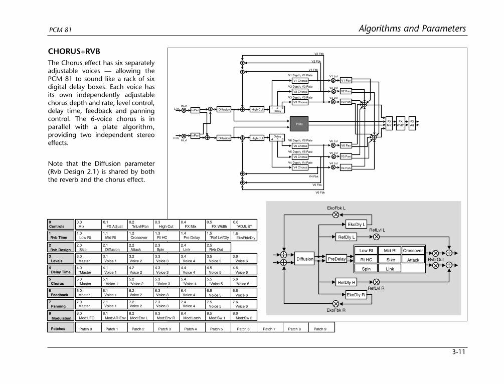
3-11
Algorithms and ParametersPCM 81
PreDelay
RefDly L
EkoFbk L
EkoDly L
RefDly R
EkoDly R
EkoFbk R
Low Rt Mid Rt
Size Attack
Spin Link
Crossover
Rt HC
RefLvl L
RefLvl R
Diffusion Rvb Out
L In
R In
InPan
InPan
InLvl
InLvl
V1 Fbk
V2 Pan
Delay
V3 Pan
31 2
V6 Pan
V5 Pan
V4 Pan
V1 Pan
V2 Fbk
V3 Fbk
Delay64 5
V4 Fbk
V5 Fbk
V6 Fbk
V1 Chorus
V1 Depth, V1 Rate
V2 Lvl
V3 Lvl
V1 Lvl
FXMix
FXWidth
V5 Lvl
V4 Lvl
V6 Lvl
FXAdj
Diffusion
Diffusion
V2 Chorus
V3 Chorus
V2 Depth, V2 Rate
V3 Depth, V3 Rate
V6 Chorus
V6 Depth, V6 Rate
V5 Chorus
V4 Chorus
V5 Depth, V5 Rate
V4 Depth, V4 Rate
Plate
High Cut
High Cut
2 2.0 2.1 2.2 2.3 2.4 2.5
3 3.0 3.1 3.2 3.3 3.4
4 4.0 4.1 4.2 4.3 4.4
5 5.0 5.1 5.2 5.3 5.4
6 6.0 6.1 6.2 6.3 6.4
7 7.0 7.1 7.2 7.3 7.4 7.5 7.6
8 8.0 8.1 8.2 8.3 8.4 8.5 8.6
0 0.0 0.1 0.2 0.3 0.4 0.5
1.51 1.0 1.1 1.2 1.3 1.4
Controls Mix
3.5 3.6
4.5 4.6
5.5 5.6
6.5 6.6
Rvb Time
Rvb Design
FX Adjust *InLvl/Pan High Cut FX Mix FX Width
Low Rt Mid Rt Crossover Rt HC Pre Delay *Ref Lvl/Dly
Size Diffusion Attack Spin Link Rvb Out
Patches Patch 5 Patch 6 Patch 7 Patch 8 Patch 9Patch 4Patch 3Patch 2Patch 1Patch 0
Modulation Mod:LFO Mod:AR Env Mod:Env L Mod:Env R Mod:Latch Mod:Sw 1 Mod:Sw 2
Feedback
Panning
Master Voice 1 Voice 2 Voice 3 Voice 4
Master Voice 1 Voice 2 Voice 3 Voice 4
Voice 5 Voice 6
Voice 5 Voice 6
1.6EkoFbk/Dly
Levels Master Voice 1 Voice 2 Voice 3 Voice 4 Voice 5 Voice 6
Delay Time *Master Voice 1 Voice 2 Voice 3 Voice 4 Voice 5 Voice 6
Chorus *Master *Voice 1 *Voice 2 *Voice 3 *Voice 4 *Voice 5 *Voice 6
0.6*ADJUST
CHORUS+RVBThe Chorus effect has six separatelyadjustable voices — allowing thePCM 81 to sound like a rack of sixdigital delay boxes. Each voice hasits own independently adjustablechorus depth and rate, level control,delay time, feedback and panningcontrol. The 6-voice chorus is inparallel with a plate algorithm,providing two independent stereoeffects.
Note that the Diffusion parameter(Rvb Design 2.1) is shared by boththe reverb and the chorus effect.
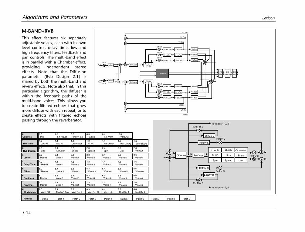
3-12
Algorithms and Parameters Lexicon
M-BAND+RVBThis effect features six separatelyadjustable voices, each with its ownlevel control, delay time, low andhigh frequency filters, feedback andpan controls. The multi-band effectis in parallel with a Chamber effect,providing independent stereoeffects. Note that the Diffusionparameter (Rvb Design 2.1) isshared by both the multi-band andreverb effects. Note also that, in thisparticular algorithm, the diffuser iswithin the feedback paths of themulti-band voices. This allows youto create filtered echoes that growmore diffuse with each repeat, or tocreate effects with filtered echoespassing through the reverberator.
L In
R In
InPan
InPan
InLvl
InLvl
V1 Fbk
V2 Pan
Delay
V2 Lvl
V3 LvlV3 Pan
31 2
V6 Pan
V5 Pan
V4 Pan
V1 Pan
V2 Fbk
V3 Fbk
V1 Lvl
DiffusionDelay
64 5
V4 HiCut
V6 HiCut
V5 LoCut
V4 LoCut
V6 LoCut
V4 Fbk
V5 Fbk
V6 Fbk
Diffusion
V2 HiCut
V3 HiCut
V1 HiCut
V2 LoCut
V3 LoCut
V1 LoCut
V5 HiCut
FXMix
FXWidth
FXAdj
V5 Lvl
V4 Lvl
V6 Lvl
Chamber
PreDelay
RefDly L
EkoFbk L
EkoDly L
RefDly R
EkoDly R
EkoFbk R
Low Rt Mid Rt
Size Shape
Crossover
Rt HC
Spin Spread Link
RefLvl L
RefLvl R
Diffusion
to Voices 4, 5, 6
to Voices 1, 2, 3
Rvb Out
2 2.0 2.1 2.2 2.3 2.4 2.5 2.6
3 3.0 3.1 3.2 3.3 3.4
4 4.0 4.1 4.2 4.3 4.4
5 5.0 5.1 5.2 5.3 5.4
6 6.0 6.1 6.2 6.3 6.4
7 7.0 7.1 7.2 7.3 7.4 7.5 7.6
8 8.0 8.1 8.2 8.3 8.4 8.5 8.6
0 0.0 0.1 0.2 0.3 0.4
1.51 1.0 1.1 1.2 1.3 1.4
Controls Mix
3.5 3.6
4.5 4.6
5.5 5.6
6.5 6.6
Rvb Time
Rvb Design
FX Adjust *InLvl/Pan FX Mix FX Width
Low Rt Mid Rt Crossover Rt HC Pre Delay *Ref Lvl/Dly
Size Diffusion Shape Spin Link Rvb Out
Patches Patch 5 Patch 6 Patch 7 Patch 8 Patch 9Patch 4Patch 3Patch 2Patch 1Patch 0
Modulation Mod:LFO Mod:AR Env Mod:Env L Mod:Env R Mod:Latch Mod:Sw 1 Mod:Sw 2
Feedback
Panning
Master Voice 1 Voice 2 Voice 3 Voice 4
Master Voice 1 Voice 2 Voice 3 Voice 4
Voice 5 Voice 6
Voice 5 Voice 6
1.6EkoFbk/Dly
Levels Master Voice 1 Voice 2 Voice 3 Voice 4 Voice 5 Voice 6
Delay Time *Master Voice 1 Voice 2 Voice 3 Voice 4 Voice 5 Voice 6
Filters *Master *Voice 1 *Voice 2 *Voice 3 *Voice 4 *Voice 5 *Voice 6
Spread
0.5*ADJUST
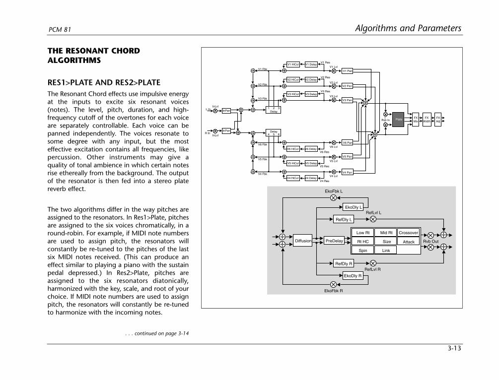
3-13
Algorithms and ParametersPCM 81
THE RESONANT CHORDALGORITHMS
RES1>PLATE AND RES2>PLATEThe Resonant Chord effects use impulsive energyat the inputs to excite six resonant voices(notes). The level, pitch, duration, and high-frequency cutoff of the overtones for each voiceare separately controllable. Each voice can bepanned independently. The voices resonate tosome degree with any input, but the mosteffective excitation contains all frequencies, likepercussion. Other instruments may give aquality of tonal ambience in which certain notesrise ethereally from the background. The outputof the resonator is then fed into a stereo platereverb effect.
The two algorithms differ in the way pitches areassigned to the resonators. In Res1>Plate, pitchesare assigned to the six voices chromatically, in around-robin. For example, if MIDI note numbersare used to assign pitch, the resonators willconstantly be re-tuned to the pitches of the lastsix MIDI notes received. (This can produce aneffect similar to playing a piano with the sustainpedal depressed.) In Res2>Plate, pitches areassigned to the six resonators diatonically,harmonized with the key, scale, and root of yourchoice. If MIDI note numbers are used to assignpitch, the resonators will constantly be re-tunedto harmonize with the incoming notes.
. . . continued on page 3-14
PreDelay
RefDly L
EkoFbk L
EkoDly L
RefDly R
EkoDly R
EkoFbk R
Low Rt Mid Rt
Size Attack
Spin Link
Crossover
Rt HC
RefLvl L
RefLvl R
Diffusion Rvb Out
L In
R In
InPan
InPan
InLvl
InLvl
V1 Fbk
V2 Pan
Delay
V2 Lvl
V3 LvlV3 Pan
FXMix
FXWidth
FXAdj
31 2
V6 Pan
V5 Pan
V4 Pan
V1 Pan
V2 Fbk
V3 Fbk
V1 Lvl
Delay64 5
V5 Lvl
V4 Lvl
V6 Lvl
V4 Fbk
V5 Fbk
V6 Fbk
Rvb In
V3 Res
V2 Res
V1 Res
V6 Res
V5 Res
V4 Res
Plate
V1 HiCut V1 Delay
V2 HiCut V2 Delay
V3 HiCut V3 Delay
V6 HiCut V6 Delay
V5 DelayV5 HiCut
V4 HiCut V4 Delay

3-14
Algorithms and Parameters Lexicon
2 2.0 2.1 2.2 2.3 2.4 2.5
3 3.0 3.1 3.2 3.3 3.4
4 4.0 4.1 4.2 4.3 4.4
5 5.0 5.1 5.2 5.3 5.4
6 6.0 6.1 6.2 6.3
7 7.0 7.1 7.2 7.3 7.4 7.5 7.6
8 8.0 8.1 8.2 8.3 8.4 8.5 8.6
0 0.0 0.1 0.2 0.3 0.4
1.51 1.0 1.1 1.2 1.3 1.4
Controls Mix
3.5 3.6
4.5 4.6
5.5 5.6
Rvb Time
Rvb Design
FX Adjust *InLvl/Pan FX Mix FX Width
Low Rt Mid Rt Crossover Rt HC Pre Delay *Ref Lvl/Dly
Size Diffusion Attack Spin Link *Rvb In/Out
Patches Patch 5 Patch 6 Patch 7 Patch 8 Patch 9Patch 4Patch 3Patch 2Patch 1Patch 0
Modulation Mod:LFO Mod:AR Env Mod:Env L Mod:Env R Mod:Latch Mod:Sw 1 Mod:Sw 2
Pitch
Panning
Assign Tuning Active Unison
Master Voice 1 Voice 2 Voice 3 Voice 4 Voice 5 Voice 6
1.6EkoFbk/Dly
Levels *Master *Voice 1 *Voice 2 *Voice 3 *Voice 4 *Voice 5 *Voice 6
Delay Time *Master Voice 1 Voice 2 Voice 3 Voice 4 Voice 5 Voice 6
Resonance *MstrRes/HC *Voice 1 *Voice 2 *Voice 3 *Voice 4 *Voice 5 *Voice 6
0.5*ADJUST
2 2.0 2.1 2.2 2.3 2.4 2.5
3 3.0 3.1 3.2 3.3 3.4
4 4.0 4.1 4.2 4.3 4.4
5 5.0 5.1 5.2 5.3 5.4
6 6.0 6.1 6.2 6.3 6.4
7 7.0 7.1 7.2 7.3 7.4 7.5 7.6
8 8.0 8.1 8.2 8.3 8.4 8.5 8.6
0 0.0 0.1 0.2 0.3 0.4
1.51 1.0 1.1 1.2 1.3 1.4
Controls Mix
3.5 3.6
4.5 4.6
5.5 5.6
6.5 6.6
Rvb Time
Rvb Design
FX Adjust *InLvl/Pan FX Mix FX Width
Low Rt Mid Rt Crossover Rt HC Pre Delay *Ref Lvl/Dly
Size Diffusion Attack Spin Link *Rvb In/Out
Patches Patch 5 Patch 6 Patch 7 Patch 8 Patch 9Patch 4Patch 3Patch 2Patch 1Patch 0
Modulation Mod:LFO Mod:AR Env Mod:Env L Mod:Env R Mod:Latch Mod:Sw 1 Mod:Sw 2
Pitch
Panning
*Master Voice 1 Voice 2 Voice 3 Voice 4
Master Voice 1 Voice 2 Voice 3 Voice 4
Voice 5 Voice 6
Voice 5 Voice 6
1.6EkoFbk/Dly
Levels *Master *Voice 1 *Voice 2 *Voice 3 *Voice 4 *Voice 5 *Voice 6
Delay Time *Master Voice 1 Voice 2 Voice 3 Voice 4 Voice 5 Voice 6
Resonance *MstrRes/HC *Voice 1 *Voice 2 *Voice 3 *Voice 4 *Voice 5 *Voice 6
0.5*ADJUST
Res1>Plate
Res2>Plate
3-15
Algorithms and ParametersPCM 81
THE PARAMETERSPCM 81 parameters are organized into labeled rows within eachedit matrix. Although there are similarities among all matrixes, suchas having a row of Controls first, and Modulation and Patchingrows last, some of the parameters within each row, and some entirerows are unique to specific algorithms.
This section contains descriptions for all PCM 81 parameters,organized alphabetically by row label as follows:
• Chorus • Modulation
• Controls • Panning
• Delay Time • Patching
• Feedback/Cross-Feedback • Pitch
• Filters • Resonance
• Glide FX • Rvb Design
• Levels • Rvb Time
Individual parameter descriptions within each row are presented,as far as possible, in the order in which they appear from left toright in the edit matrix.
CHORUSIn the Chorus+Rvb algorithm, Row 5 provides parameters whichprovide rate and depth controls for each of the six chorus voices,as well as master rate and depth controls.
MstDepth and MstRate
Two Master Chorus parameters in the first row position allowChorus, Depth and Rate for all voices to be simultaneously scaled.Each control has a range of 0-200%. Press Load/ to togglebetween MstDepth and MstRate.
Voices (Depth and Rate)
Each voice position has Depth and Rate controls to set the timerange (delay) and rate of change across that time range (pitch) ofthe chorusing effect. (Press Load/ to toggle between them.)Depth provides settings of 0-500ms in single millisecondincrements. Rate parameter can be set to 0Hz (Off), or to one ofone-hundred selections from 0.01-3.50Hz. Depths of 10-30mscombined with Rates as high as 0.50Hz provide subtle chorusingand multivoicing effects. Depths of hundreds of millisecondscombined with higher Rates provide a wide range of pitch shiftingeffects.
CONTROLSRow 0 of every algorithm contains parameters that provideoverall control of both the reverb and voice effects.
Mix
Mix controls the ratio of dry and wet signal present at the PCM 81outputs. When the PCM 81 is patched into a console or aninstrument amplifier through an auxiliary or effects loop, thiscontrol should always be set to 100% wet. (Control Mode 1.1allows you to select a global Mix setting.) When an instrument isplugged directly into the PCM 81, a setting between 45 and 65%is a good starting point.
. . . continued on page 3-16

3-16
Algorithms and Parameters Lexicon
CONTROLS (continued)
FX Adjust
FX Adjust controls the level of the processed (wet) signal before itis mixed with the dry signal (if any) and sent to the audio outputs.The range of this parameter is +12dB to -73dB, and Off (wetoutput muted.) FX Adjust is inactive when the PCM 81 is in Bypassmode, so it is a good idea to compare the levels with Bypass on andoff while editing this parameter. Adjust it until the audio levelsounds the same with bypass on and off.
InLvl L&R, InPan L&R
InLvl L and InLvl R control the level and phase of the unprocesseddry signal into the effects. The range of these parameters is fromFull (0dB) Phase Normal, to -85dB Phase Normal, Off, -85dB PhaseInverted to Full (0dB) Phase Inverted.
InPan L and InPan R control the location of the left and right inputaudio as a stereo image to the effect's audio input. Unmodifiedstereo imaging to the effects can be achieved by setting InPan Lhard left (50L) and InPan R hard right (50R). Changing InPanL toany other value (49L to 50R), takes the left audio input andpresents it as a panned source to the effect's left and right input.Changing InPan R to any value other than 50R, does the same forthe right audio input.
High Cut
High Cut sets the high frequency cutoff of a low-pass filter. Thisparameter affects both channels.
Voice Dif
This parameter is available in all of the 4-Voice Algorithms, and inGlide>Hall. It controls the density of echoes in the delay voices,independently of Reverb diffusion. High levels of diffusion thicken,or smear, the echoes. This is most noticeable on material with sharptransients.
FX Mix
FX Mix controls the balance of reverb and non-reverb effects.(Non-reverb effects are those processed as "voices" controlled bylevel, delay and feedback parameters generally found in rows 3-7.)The range of this control is 0 to 100%.
FX Width
FX Width can be thought of as an extension of typical mono tostereo imaging controls. The range of this parameter is -360 to+360, in single digit increments. Values of -360, 0, or +360 causethe effect's audio output to be mono. Values of -315 and +45 causethe output to be normal left/right stereo. Values of -45 and +315cause "swapped", or right/left stereo.
The large and duplicated range of this parameter allows smoothglides from any Left/Right Mix, Phase, Mono/Stereo image point toany other. These are on the output of the FX Mix. Of particularinterest are: 0 MONO, 45 STEREO, and 90 L–R, R–L (surroundchannel). This parameter can be changed in real-time forfascinating spatial effects.
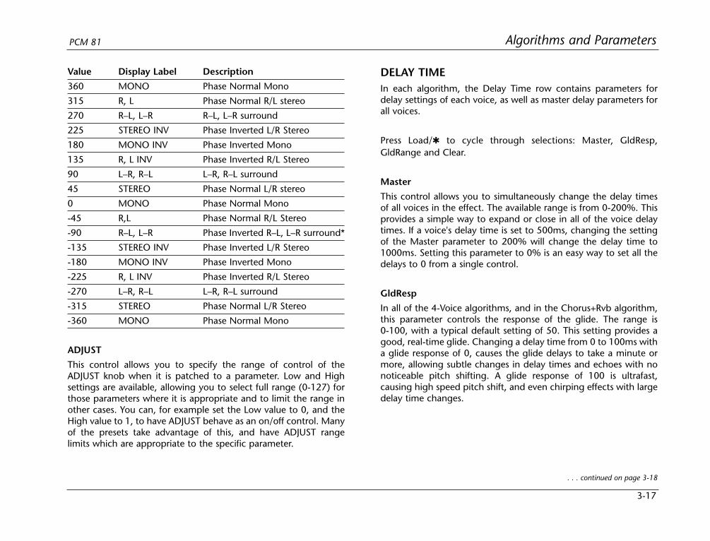
3-17
Algorithms and ParametersPCM 81
DELAY TIMEIn each algorithm, the Delay Time row contains parameters fordelay settings of each voice, as well as master delay parameters forall voices.
Press Load/ to cycle through selections: Master, GldResp,GldRange and Clear.
Master
This control allows you to simultaneously change the delay timesof all voices in the effect. The available range is from 0-200%. Thisprovides a simple way to expand or close in all of the voice delaytimes. If a voice's delay time is set to 500ms, changing the settingof the Master parameter to 200% will change the delay time to1000ms. Setting this parameter to 0% is an easy way to set all thedelays to 0 from a single control.
GldResp
In all of the 4-Voice algorithms, and in the Chorus+Rvb algorithm,this parameter controls the response of the glide. The range is0-100, with a typical default setting of 50. This setting provides agood, real-time glide. Changing a delay time from 0 to 100ms witha glide response of 0, causes the glide delays to take a minute ormore, allowing subtle changes in delay times and echoes with nonoticeable pitch shifting. A glide response of 100 is ultrafast,causing high speed pitch shift, and even chirping effects with largedelay time changes.
. . . continued on page 3-18
Value Display Label Description
360 MONO Phase Normal Mono
315 R, L Phase Normal R/L stereo
270 R–L, L–R R–L, L–R surround
225 STEREO INV Phase Inverted L/R Stereo
180 MONO INV Phase Inverted Mono
135 R, L INV Phase Inverted R/L Stereo
90 L–R, R–L L–R, R–L surround
45 STEREO Phase Normal L/R stereo
0 MONO Phase Normal Mono
-45 R,L Phase Normal R/L Stereo
-90 R–L, L–R Phase Inverted R–L, L–R surround*
-135 STEREO INV Phase Inverted L/R Stereo
-180 MONO INV Phase Inverted Mono
-225 R, L INV Phase Inverted R/L Stereo
-270 L–R, R–L L–R, R–L surround
-315 STEREO Phase Normal L/R Stereo
-360 MONO Phase Normal Mono
ADJUST
This control allows you to specify the range of control of theADJUST knob when it is patched to a parameter. Low and Highsettings are available, allowing you to select full range (0-127) forthose parameters where it is appropriate and to limit the range inother cases. You can, for example set the Low value to 0, and theHigh value to 1, to have ADJUST behave as an on/off control. Manyof the presets take advantage of this, and have ADJUST rangelimits which are appropriate to the specific parameter.
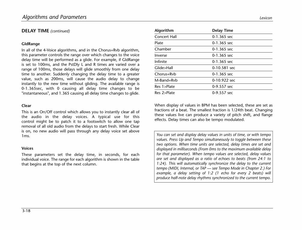
3-18
Algorithms and Parameters Lexicon
DELAY TIME (continued)
GldRange
In all of the 4-Voice algorithms, and in the Chorus+Rvb algorithm,this parameter controls the range over which changes to the voicedelay time will be performed as a glide. For example, if GldRangeis set to 100ms, and the PstDly L and R times are varied over arange of 100ms, those delays will glide smoothly from one delaytime to another. Suddenly changing the delay time to a greatervalue, such as 200ms, will cause the audio delay to changeinstantly to the new time without gliding. The available range is0-1.365sec, with 0 causing all delay time changes to be"instantaneous", and 1.365 causing all delay time changes to glide.
Clear
This is an On/Off control which allows you to instantly clear all ofthe audio in the delay voices. A typical use for thiscontrol might be to patch it to a footswitch to allow one tapremoval of all old audio from the delays to start fresh. While Clearis on, no new audio will pass through any delay voice set above1ms.
Voices
These parameters set the delay time, in seconds, for eachindividual voice. The range for each algorithm is shown in the tablethat begins at the top of the next column.
Algorithm Delay Time
Concert Hall 0-1.365 sec
Plate 0-1.365 sec
Chamber 0-1.365 sec
Inverse 0-1.365 sec
Infinite 0-1.365 sec
Glide>Hall 0-10.581 sec
Chorus+Rvb 0-1.365 sec
M-Band+Rvb 0-10.922 sec
Res 1>Plate 0-9.557 sec
Res 2>Plate 0-9.557 sec
When display of values in BPM has been selected, these are set asfractions of a beat. The smallest fraction is 1/24th beat. Changingthese values live can produce a variety of pitch shift, and flangeeffects. Delay times can also be tempo modulated.
You can set and display delay values in units of time, or with tempovalues. Press Up and Tempo simultaneously to toggle between thesetwo options. When time units are selected, delay times are set anddisplayed in milliseconds (From 0ms to the maximum available delayfor that parameter). When tempo values are selected, delay valuesare set and displayed as a ratio of echoes to beats (from 24:1 to1:24). This will automatically synchronize the delay to the currenttempo (MIDI, Internal, or TAP — see Tempo Mode in Chapter 2.) Forexample, a delay setting of 1:2 (1 echo for every 2 beats) willproduce half-note delay rhythms synchronized to the current tempo.

3-19
Algorithms and ParametersPCM 81
FEEDBACK/CROSS FEEDBACKParameters in this row provide level and phase setting for feedbackof individual voices, as well as a master feedback parameter for allvoices. In the Glide>Hall algorithm, a duplicate set of parameters isincluded for cross-feedback.
Master
A Master Feedback control is available in effects with a feedbacklevel control for each voice. It allows the feedback level for allvoices to be simultaneously adjusted over a range of 0-100%.
Voices
In the 4-Voice algorithms, four voice controls are provided foradjustment of the level and polarity of signals recirculated back tothe input of individual voices. Note that, as Voices 1 and 2 andVoices 3 and 4 are paired, caution should be observed not tocreate feedback within a pair which exceeds more than 100%.
In the Chorus+Rvb and M-Band+Rvb algorithms, six voiceparameters control the feedback level of the voice delays. Voices 1,2, and 3 Fbk control the individual voice feedback levels from theleft channel voice delay outputs to the left channel delay feedbackinput. Voices 4, 5, and 6 Fbk control the individual voice feedbacklevels from the right channel voice delay outputs to the rightchannel delay feedback input. The range of these parameters isfrom +100% down to 1% (Phase Normal feedback), 0% (Off), –1%up to –100% (Phase Inverted feedback).
In the Glide>Hall algorithm, the Feedback row provides bothFeedback and Cross Feedback parameters as described below. PressLoad/ at each row position to toggle between Feedback andCross Feedback parameters.
Mstr Fbk, Mstr X-Fbk
These parameters allow the feedback and cross feedback levels forall voices to be simultaneously scaled over a range of 0-100%.
Voices 1-6 Fbk, X-Fbk
These parameters control the feedback and cross feedback levelsand the polarity of the voice delays.
Voices 1, 2, and 3 Fbk control the individual voice feedback levelsfrom the left channel voice delay outputs to the left channel delayfeedback input.
Voices 1, 2, and 3 X-Fbk control the individual voice feedbacklevels from the left channel voice delay outputs to the right chan-nel delay feedback input.
Voices 4, 5, and 6 Fbk control the individual voice feedback levelsfrom the right channel voice delay outputs to the right channeldelay feedback input.
Voices 4, 5, and 6 X-Fbk control the individual voice feedbacklevels from the right channel voice delay outputs to the leftchannel delay feedback input. The range of these parameters isfrom +100% down to 1% (Phase Normal feedback), 0% (off), –1%up to –100% (Phase Inverted feedback).
The sum of all Fbk and X-Fbk values for each channel should be lessthan 100%.
3-20
Algorithms and Parameters Lexicon
FILTERSIn the M-Band+Rvb algorithm, Row 5 contains parameters forcut-off frequencies of low and high cut filters for each voice, as wellas master low and high cut controls for all voices.
Mstr LC/HC
Two master controls are provided in the first row position. PressLoad/ to toggle between them. The High Cut Master allowssimultaneous adjustment of the high frequency cut-off points forthe filters on all voices in single semitone increments up or downfrom the individual voice settings. The Low Cut Master allowssimultaneous adjustment of the low frequency cut off points for thefilters on all voices in single semitone increments up or down fromthe individual voice settings.
V1-V6 LoCut and HiCut
The low cut and high cut filters operate at 12dB/octave. Each of sixvoices has individual low cut and high cut filters. The ranges of thefilter cut-off points are from 20-20,000Hz at approximatelysemitone intervals across the entire range for a total of 121 cut offpoints. The low cut filters have an OFF position just below 20Hz.The high cut filters have an OFF position just above 20,000Hz.
GLIDE FXIn the Glide>Hall algorithm, Row 3 contains level, delay andfeedback parameters for a pair of stereo gliding delays thatpreceded the 6-voice delay.
Gld Lvl
Gld Lvl controls the stereo output level from all gliding delays (A,B, Left and Right). It has a range of Full (0dB) down to -85dB andOff.
A Left (A Lvl L and A Dly L)
These parameters control the output level and delay time of the leftchannel A Glide Delay. A Lvl L has a range of Full (+0dB), PhaseNormal down to -85dB, Phase Normal, OFF, -85dB Phase Invertedup to Full (+0dB), Phase Inverted. A Dly L has a range of 0.0milliseconds to 42.0 milliseconds in 0.1 millisecond units.
A Right (A Lvl R and A Dly R)
These parameters control the output level and delay time of theright channel A Glide Delay. They have the same ranges as A Left.
B Left (B Lvl L and B Dly L)
These parameters control the output level and delay time of the leftchannel B Glide Delay. They have the same ranges as A Left.
B Right (B Lvl R and B Dly R)
These parameters control the output level and delay time of theright channel B Glide Delay. They have the same ranges as A Left.
Fbk L/R
These parameters control the feedback levels of the correspondingleft and right channel Glide Delays. The range of these parametersis from +100% down to 1% (Phase Normal feedback), 0% (off),-1% up to –100% (Phase Inverted feedback).
X-Fbk L/R
These parameters control the corresponding cross feedback levelsof the left and right channel glide delays. Specifically, X-Fbk Lcontrols the feedback from the left channel A+B glide delay outputto the right channel glide delay feedback input. X-Fbk R controlsthe feedback from the right channel A+B glide delay output to the
3-21
Algorithms and ParametersPCM 81
left channel glide delay feedback input. The range of theseparameters is from +100% down to 1% (Phase Normal feedback),0% (off), -1% up to –100% (Phase Inverted feedback).
LEVELSIn each algorithm, the Levels row contains parameters for thephase and level of each voice, as well as a master level parameterfor all voices.
Master
The Master Level controls the overall level in effects which havemore than one voice. This permits simultaneous changes in allvoice levels without altering the balance between individual voices.
In the Res1>Plate and Res2>Plate algorithms, the Master parame-ter contains two master parameters for the six resonator voices:Mstr Lvl and Mstr Fbk. (Load/ will toggle between them.) Mstr Lvlis a master level control for all of the resonator voices, as describedabove. Use care when adjusting this value. The resonators will putout high levels if the input source has any components that areclose in pitch to the resonator tunings. In general, this controlshould be set to 0dB or less.
The Mstr Fbk control allows the feedback levels for all voices to bescaled over a range of 0-100%.
Voices
Individual controls are provided for each Voice Level. Voices can beturned completely off, full on, or set to any point between, in 1dBincrements. There are as many voice level controls as there arevoices in an effect.
In the Res1>Plate and Res2>Plate algorithms, positions 1-6 containboth level and feedback parameters for each of the six resonatorvoices. (Load/ will toggle between them.) Lvl controls theindividual level and polarity for each voice. Voices can be turnedcompletely off, full on, or set to any point in between in 1dBincrements. Use care when adjusting this value. The resonators willput out high levels if the input source has any components that areclose in pitch to the resonator tunings. In general, this controlshould be set to a value less than Full.
The Fbk controls set the feedback level and polarity of each voice.Voices 1-3 Fbk control the feedback levels from the left channeldelay voice outputs to the left channel delay voice inputs. Voices4-6 Fbk control the feedback levels from the right channel delayvoice outputs to the right channel delay voice inputs. The sum ofthe values for either side should be less than 100%. (Disregard thenegative sign when adding values.)
MODULATIONThe Modulation row, which is the same for every algorithm,contains the parameters for the PCM 81's internal modulationsources. Use the Patch row to assign these modulators to any PCM81 effect parameter.
Mod: LFO
Four parameters are available: Shape, P Width, Depth, and Rate.
• Shape Allows you to select the wave shape that willbe used when "LFO" is selected as a patchSource. The choices are: Sine, Cosine, Square,Sawtooth, Pulse, and Triangle.
. . . continued on page 3-22

3-22
Algorithms and Parameters Lexicon
MODULATION (continued)
• P Width Determines the proportion of each pulse wavecycle for which the LFO is on (1-99%). Forexample, setting P Width to 50% means thatthe LFO is on for half of its cycle. The effect ofthis control will only be heard if you are usingthe Pulse shape.
• Depth Scales the output of the LFO from 0 to 100%.
• Rate Sets the speed (0-25Hz) at which the LFOcycles. It can be set in time values (such as1.5Hz) or in tempo values (such as 3:2 cyclesper beat). Simultaneously pressing Up andTempo will toggle these two display options.
The PCM 81 allows six LFO shapes (sine, cosine, sawtooth, triangle,square and pulse) to be selected as patch Sources, as well as theLFO itself. All of these are generated by a single LFO, and arecontrolled by the single Rate control. When "LFO" is selected as apatch Source, the output will be the Shape selected here. Theamplitude of the LFO output is controlled by Depth. Both Shapeand Depth are available as patch Destinations and can becontrolled externally. Shape, Pulse Width, Depth, and Rate are allavailable as patch Destination parameters, and can be controlledexternally. See Patching in Chapter 2.
Mod: AR Env
This envelope generator's output, when turned on, will go from 0to127. How quickly it goes from 0 to 127 is determined by thesetting of Attack (0-10 seconds). Once the envelope generator has
reached 127, it remains there as long as it is turned on. When it isturned off, it goes from 127 to 0, at the rate determined by Release(0 to 10 seconds).
T Src allows you to select a Source to turn the envelope generatoron and off. T Lvl allows you to select a specific threshold valuewhich the T Src must reach to turn the envelope generator on.
The Mode parameter allows you to determine the behavior of theenvelope controller in relation to the threshold value. Four settingsare available: Repeat, One Shot, Retrigger, and Off.
MOD:LFO
Sine
Cosine
Square
Sawtooth
Pulse
Triangle
Rate
Depth
LFO
PatchSources
Shape
Clk Cmnds
High Note
Env L
Env R
Shape, Rate and Depth can be controlled by a patch.

3-23
Algorithms and ParametersPCM 81
• Repeat As long as the threshold source remains at orabove T Lvl, the envelope cycles from attack torelease. If A=R, the output of the envelope is atriangle wave.
• One Shot Once T Lvl is reached, the envelope will gothrough its entire attack cycle. Once the attackcycle is completed, if Source value is below TLvl, the envelope will immediately fall at thespecified Release rate. The envelope will gothrough its entire release cycle, even if thesource subsequently rises above T Lvl. If theSource value is at or above T Lvl, the envelopewill remain at 127 until the T Src falls.
• Retrigger As long as the level is at or above T Lvl, theenvelope will go through its attack cycle. If thelevel falls below T Lvl before attack iscompleted, the envelope immediately beginsto release.Likewise, if the T Lvl is crossed againbefore the release is completed, the attackcycle will begin again.
• Off This control turns the AR envelope off (andfrees up processor time). To optimize PCM 81real-time response, set AR Env to Off when it isnot being used.
Mod: Env L and Mod: Env R
These are left and right input signal envelope followers. The onlyavailable parameter is Release which is set in milliseconds. Thiscontrol allows you to specify the release rate (0-10 seconds) whenthe input level drops.
Mod: Latch
The latch is a very flexible modulation source. It can be used to dosuch things as derive a switch from a continuous “return to zero”source (like MIDI After Touch). It can turn a momentary (on/off)footswitch into a latching footswitch (push on/ push off), and itcan divide the switching rates of sources in half or thirds.
The latch has three parameters: Src, High and Low. Any patchsource can be the Src (See Source listing under Patching.) High andLow are threshold values. The latch works as follows:
High
Low
127
0With High set to 127, and Low set to 0,
no latching will occur. The output isidentical to the output of the selected source.
High
Low
127
0With High set to less than 127, and Lowset to 0, the High value will be latched.
High
Low
127
0With High set to 127, and Low set to a valuegreater than 0, the Low value will be latched.
HighLow
127
0With High set to less than 127, andLow set to a value greater than 0,
both values are latched.
. . . continued on page 3-24

3-24
Algorithms and Parameters Lexicon
MODULATION (continued)
Mod: Latch (continued)
There is no output from the latch until the Src value falls within therange defined by the settings of High and Low. While the sourcevalue is between these thresholds, the output of the latch is thesame value as the source. When the source value reaches or passeseither threshold, the output of the latch holds at the limit valueuntil the source value passes through the threshold twice. The latchcan be set to hold at either the low threshold, the high threshold,or both. Setting Low to 0 disables latching at the low threshold.Setting High to 127 disables latching at the high threshold.
See preset P0 3.0 FSw2 Rotary as an example.
Mod: Sw 1 and Mod: Sw 2
These are identical time switches. Each has five parameters: Rate, PWidth, Mode, T Lvl and T Src.
• Rate Sets the speed at which the switch cycles. Itcan be set in time values (such as 1.5 Hz) ortempo values (such as 3:2 Cycles per Beat).Simultaneously pressing Up and Tempo willtoggle these display options.
• P Width Determines the proportion of each switchcycle during which the switch is on. Forexample, setting P Width to 50% means thatthe switch is on for one-half of a cycle.
• Mode Determines the “shape” of the switch output.Three settings are available: Switch, Ramp,and Off. When Switch is selected, thetransition from on to off is instantaneous, i.e.the switch output resembles a pulse wave.When Ramp is selected, the transition from onto off is continuous, i.e. the switch outputresembles a triangle or sawtooth wave.
• Off Turns the switch off (and frees up processortime). To optimize PCM 81 real-time response,set switch to Off when it is not being used.
• T Lvl Sets the threshold value at which the switchwill begin to cycle.
• T Src Selects a patch source to drive the switch. Theoutput of the switch is 0 as long as T Src is setto a value below T Lvl. Once the source valuereaches or passes T Lvl, the switch will begin tocycle between on (127) and off (0) at thespeed set by Rate.
Note that both Rate and P Width are available as patchDestinations, allowing them to be dynamically controlled by otherpatch sources. Switches are reset to the beginning of their cycleswhenever Tap is pressed.
A special, composite output of these switches, called Sw 1&2 isavailable as a patch source. The value of Sw 1&2 alternatesbetween the output of Sw 1 and the output of Sw 2. Thealternation occurs on the transition from on to off. Note that bothSw 1 and Sw 2 must be active for the alternation to occur.

3-25
Algorithms and ParametersPCM 81
PANNINGParameters in the Panning row provide control of panning ofindividual effects voices, as well as a master panning parameter forall voices.
Master
The Pan Master provides simultaneous control over the panning ofall voices in the effect. The range of the Pan Master is 50L (full left)through L1, C (Center), 1R through 50R (full right) for a total of101 positions. The Master Pan is additive to the individual voicepanners such that, if a voice is set to L10, and the Master is set to20R, the voice will be at 10R.
Voices
Individual pan controls are provided to position the output of eachvoice. The range of each voice is 50L (full left) through 1L, C(Center), 1R through 50 R(full right) for a total of 101 positions.
PATCHINGThe last row of each algorithm's edit matrix is the Patch row. Thisrow provides parameters for creating up to 10 patches in eacheffect. Each row position (Patch 0-9) has three controls available:Src, Dst, and Values. Press Load/ to cycle among these selections.
Src
Use ADJUST to select any of the sources listed below.
Dst
Use ADJUST to select any parameter except those on the Patch row.
. . . continued on page 3-26
127T Lvl
0The switch cycles between 127 and 0as long as T Src is at or above T Lvl.
SwitchMode
When Switch Mode is selected, transitionfrom 127 to 0 is instantaneous.
T Src
Sw Value
RampMode
When Ramp Mode is selected, transitionfrom 127 to 0 is continuous.
127
0P Width50 P Width
25
P Width75
P Width50 P Width
25
P Width75
127
0
Sw 11 Cycl:2 BeatP Width = 50
Sw 21 Cycl:3 BeatP Width = 16
Sw 1&2
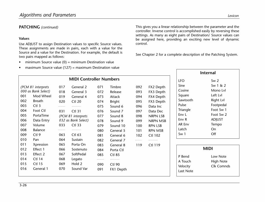
3-26
Algorithms and Parameters Lexicon
PATCHING (continued)
Values
Use ADJUST to assign Destination values to specific Source values.These assignments are made in pairs, each with a value for theSource and a value for the Destination. For example, the default istwo pairs mapped as follows:
• minimum Source value (0) = minimum Destination value
• maximum Source value (127) = maximum Destination value
This gives you a linear relationship between the parameter and thecontroller. Inverse control is accomplished easily by reversing thesesettings. As many as eight pairs of Destination/ Source values canbe assigned here, providing an exciting new level of dynamiccontrol.
See Chapter 2 for a complete description of the Patching System.
LFOSineCosineSquareSawtoothPulseTriangleEnv LEnv RAR EnvLatchSw 1
Sw 2Sw 1 & 2Mono LvlLeft LvlRight LvlFootpedalFoot Sw 1Foot Sw 2ADJUSTTempoOnOff
Internal
(PCM 81 interprets000 as Bank Select)001 Mod Wheel002 Breath003 Ctl 3004 Foot Ctl005 PortaTime006 Data Entry007 Volume008 Balance009 Ctl 9010 Pan011 Xpression012 Effect 1013 Effect 2014 Ctl 14015 Ctl 15016 General 1
017 General 2018 General 3019 General 4020 Ctl 20
031 Ctl 31(PCM 81 interprets032 as Bank Select)033 Ctl 33
063 Ctl 63064 Sustain065 Porta On066 Sostenuto067 SoftPedal068 Legato069 Hold 2070 Sound Var
071 Timbre072 Release073 Attack074 Bright075 Sound 6076 Sound 7077 Sound 8078 Sound 9079 Sound 10080 General 5081 General 6082 General 7083 General 8084 Porta Ctl085 Ctl 85
090 Ctl 90091 FX1 Depth
092 FX2 Depth093 FX3 Depth094 FX4 Depth095 FX5 Depth096 Data Inc097 Data Dec098 NRPN LSB099 NRPN MSB100 RPN LSB101 RPN MSB102 Ctl 102
119 Ctl 119
MIDI Controller Numbers
P BendA TouchVelocityLast Note
Low NoteHigh NoteClk Comnds
MIDI

3-27
Algorithms and ParametersPCM 81
PITCHThe Resonant Chord algorithms: Res1>Plate and Res 2>Plate eachhave a Pitch row that contains the parameters for setting andcontrolling the tuning of the effect's resonators. Each set ofparameters is presented separately here.
Res 1>Plate Pitch ParametersThe voice resonators take the audio impulse from a delay voice and“resonate” it at a desired pitch. Until a resonator is assigned apitch, it does not resonate. The Res1 effect is a “round robin” pitchassign in that pitch changes are individually assigned to one of (asmany as) six voice resonators. For example, assume that all sixvoice resonators are active in the newly loaded effect, and the firstpitch assigned is A4. Voice 1’s resonator will be set to the A4frequency. Assign B4, and Voice 2’s resonator will be set to thatpitch. In this example, if we assign four more pitches (D5, G4,A#:Bb4, C5, for example), they will be assigned to the Voice 3, 4,5, and 6 resonators, respectively. If a seventh pitch is assigned, forexample, F3, Voice 1’s resonator will be changed from A4 to F3(the other resonators remain at the last assigned pitches).
Assign
This parameter has a range of C0 to G10 (128 pitches) to beconvenient for MIDI patching. As the value of this parameter ischanged, each “next value” is assigned to the next active pitchresonator of the six possible active resonators. An example mightbe driving this parameter with a slow LFO to achieve an effectsomething like strumming the strings of an open piano.
Tuning
This parameter allows you to tune the A440 reference of the boxanywhere from 430.0-450.0Hz in 0.1Hz increments.
Active
This parameter allows you to define the number of active voiceresonators. You can choose from 0 (no resonators active) to 6.Setting the value to 1 will limit pitch assignments to Voice 1’sresonator. Setting the value to 2 will limit the round robin pitchassign to Voices 1 and 2. A value of 6 uses all the voice resonators.
A handy feature of this parameter is the ability to mute resonators.For example, you can patch this parameter to a footswitch orpedal, allowing you to drive the parameter value down to 0 at anytime, causing the resonators to stop playing their last assignedpitches. You can then immediately drive it back up to the desirednumber of active resonators. This “clears” the pitch assign for theresonators, so they don’t go back to playing their previous pitches,but rather wait for the next pitch assign to come along beforeresonating.
Unison
This is a simple On/Off control. When set to On, pitch assigns willbe sent simultaneously to all active resonators. When set to Off,pitch assigns will operate in the round robin method describedearlier. This allows you to set multiple delay times for all Voices andallows a single pitch assign (rather than 6 individual assigns) to setall the resonators to the same pitch. The pitch will ring out at 6different delay times from the input impulse.
Res 2>Plate Pitch ParametersThe voice resonators take the audio impulse from a delay voice and“resonate” it at a desired pitch. The Res2 effect is a “intervalharmonization” pitch assign in that pitch changes generateinterval pitches to be assigned to the six voice resonators.
. . . continued on page 3-28
3-28
Algorithms and Parameters Lexicon
PITCH (continued)
Res 2>Plate Pitch Parameters (continued)
Position 0 contains all of the pitch parameters which affect thevoices in the remaining position in the row. Press Load/ to cyclethrough the selections at position 0: Assign, Tuning, Active, Key,Scale, Root and Rule.
Assign
This parameter has a range of C0 to G10 (128 pitches to beconvenient for MIDI patching). As the value of this parameter ischanged, each voice resonator is set to a pitch at the definedvoice’s interval (described later).
Tuning
This parameter allows you to tune the A440 reference of the boxanywhere from 430.0-450.0Hz in 0.1Hz increments.
Active
This parameter allows you to define the number of voice resonatorswhich are active. You can choose from 0 (no resonators active) to6. Setting the value to 1 will permit only Voice 1’s resonator to ringout. Setting the value to 2 will permit Voices 1 and 2 to ring out. Avalue of 6 uses all the voice resonators. A handy feature of thisparameter is the ability to mute resonators. For example, you canpatch this parameter to a footswitch or pedal, allowing you to drivethe parameter value down to 0 at any time, causing the resonatorsto stop playing their last assigned pitches. You can thenimmediately drive it back up to the desired number of activeresonators. This “clears” the note assign for the resonators, so theydon’t go back to playing their previous pitches, but rather wait forthe next pitch assign to come along before resonating.
Key
This parameter establishes a key signature for the pitch selection ofthe voice intervals. The range of this value is the 12 keys from C,C#, etc., up to B.
Scale
This parameter establishes one of two scales of semitones: astandard Major scale (intervals of 2, 2, 1, 2, 2, 2, 1 half steps for thescale), or a Harmonic scale (intervals of 2, 1, 2, 2, 1, 3, 1).
Root
This parameter (with values of 1-7) establishes the root of the scalewhich, when combined with the scale, defines the mode. Forexample, with a Major scale selected, roots 1-7 define the modes— Ionian (Major), Dorian, Phrygian, Lydian, Mixolydian, Aeolian(minor) and Locrian.
Rule
This parameter has four values: Round Down, Round Up, ShiftDown, and Shift Up. Its exclusive purpose is to tell the intervalharmonizer what to do with out-of-key pitch assignments. Thevalues instruct the interval harmonizer as follows:
Both of these generate in-key harmonization:
• Round Down Take the input pitch assign, round it down ahalf-step to an in key pitch, then calculate theinterval pitch.
• Round Up Take the input pitch assign, round it up ahalf-step to an in key pitch, then calculate theinterval pitch.

3-29
Algorithms and ParametersPCM 81
Both of these generate out-of-key harmonization:
• Shift Down Take the input pitch assign, round it up ahalf-step to an in-key pitch, calculate theinterval pitch then shift the interval pitchdown a half-step.
• Shift Up Take the input pitch assign, round it down ahalf-step to an in-key pitch, calculate theinterval pitch then shift the interval pitch up ahalf-step.
Unison and Octave interval pitches strictly follow the input pitchassign. An example of how to use these follows the explanation ofVoice Pitch intervals.
V1-V6 Pitch
The Res2>Plate effect has an individual pitch interval control foreach voice resonator. The range of each control is up or down anyscale interval through five octaves and Unison, for a total of 81possible settings. For example: an interval of up one-fifth reads"+5th", and an interval of up one octave and a fifth reads "+1 Oct+5th". Down one-fifth reads "–5th", down one octave and a fifthreads "–1 Oct –5th".
An Example Application of Key, Scale, Root, Rule andVoice Pitch Intervals• Active resonators set to 3.
• The Key is C.
• The Scale is Major.
• The Root is 1. (C Major Ionian)
• Voice 1 Pitch is assigned to Unison.
• Voice 2 Pitch is assigned to +3rd.
• Voice 3 Pitch is assigned to +5th. (Basic triad)
In-key pitch assignment examples:
1. Pitch Assign:C4. Voice 1 will resonate at C4, Voice 2 at E4, andVoice 3 at G4. (Standard chord in the key based on the tonic)
2. Pitch Assign: D4. Voice 1 will resonate at D4, Voice 2 at F4, andVoice 3 at A4. (Standard chord in the key based on thesupertonic)
3. Pitch Assign: E4. Voice 1 will resonate at E4, Voice 2 at G4, andVoice 3 at B4. (Standard chord in the key based on themedian)
4. Pitch Assign: B4. Voice 1 will resonate at B4, Voice 2 at D5, andVoice 3 at F5. (Standard chord in the key based on the leadingtone)
Out-of-key pitch assignment — Pitch Assign: C#:Db4. Rule:
• Round Down Voice 1 will resonate at C#/Db4, Voice 2 at E4,and Voice 3 at G4 diminished
• Round Up Voice 1 will resonate at C#/Db4, Voice 2 at F4,and Voice 3 at A4 augmented
• Shift Down Voice 1 will resonate at C#/Db4, Voice 2 at E4,and Voice 3 at G#:Ab4 minor
• Shift Up Voice 1 will resonate at C#/Db4, Voice 2 at F4,and Voice 3 at G#:Ab4 Major
3-30
Algorithms and Parameters Lexicon
RESONANCEIn the Resonant Chord algorithms: Res1>Plate and Res2>Plate, thisrow contains high cut filter and resonance controls for each voice,as well as master high cut and resonance controls for all voices.
Mstr Res,Mstr HC
Position 0 of the Resonance row contains two master parametersfor the six resonator voices: Mstr Res and Mstr HC. (Press Load/to toggle between them.) Mstr Res is a master resonance controlfor all of the resonator voices. It allows the resonance settings forall voices to be scaled over a range of 0-100%. Use care whenadjusting this value. The resonators will put out high levels if theinput source has any components that are close in pitch to theresonator tunings. The Mstr HC control allows the high cut filtersettings for all voices to be scaled over a range of 0-100%.
V1Res,V1 HiCut-V6 Res,V6 HiCut
TheV1-V6 Res controls set the amount and polarity of feedback foreach voice. The HiCut controls set the high frequency cutofffrequency of the 6dB per octave low pass filter for each voice.
RVB DESIGNThe Reverb Design row, available in every algorithm, containsparameters that affect the structural aspects of the reverb effect.
Size
Size sets the rate of diffusion build-up after the initial period (whichis controlled by Diffusion). Size changes a reverb sound from verylarge to very small. Generally, set this control to the approximatesize of the acoustic space being created, before adjusting anythingelse. The size in meters is roughly equal to the longest dimensionof the space. Audio is temporarily muted when Size is changed.
Duration
In the Inverse algorithm, Duration determines the length of time,in milliseconds, which passes before the cutoff in Inverse effects.
Attack
Attack is provided in the Plate algorithm to set the sharpness of theinitial response to an input signal. High settings cause an explosivesound, while low settings cause the sound to build up moreslowly with time. Attack only affects the level of sound within thefirst 50 milliseconds.
Diffusion
A Diffusion control is provided in all algorithms. It controls thedegree to which initial echo density increases over time. Highsettings of Diffusion result in initial build-up of echo density, andlow settings cause low initial build-up. Echo density is also affectedby Size; smaller spaces will sound denser. To enhance percussion,use high settings of Diffusion. For clearer and more natural vocals,mixes, and piano music, use low or moderate settings of Diffusion.
Shape, Spread
In the Chamber and Infinite algorithms, Shape and Spread worktogether to control the overall ambience of the reverb. Shapedetermines the contour of the reverb envelope. With Shape all theway down, reverb builds explosively, and decays quickly. As Shapeis advanced, reverb builds up more slowly and sustains for the timeset by Spread. With Shape in the middle, the build-up and sustainof the reverb envelope emulates a large concert hall (assuming thatSpread is at least halfway up, and that Size is suitably large — 30meters or more). Low Spread settings result in a rapid onset ofreverb at the beginning of the envelope, with little or no sustain.Higher settings spread out both buildup and sustain. In the Inversealgorithm, Spread is fixed, and only a Shape control is available.
3-31
Algorithms and ParametersPCM 81
Def
Available in the Concert Hall and Glide>Hall algorithms, Definitionaffects the echo density buildup rate during the latter part of thedecay period. At 0, the rate is determined by the programmaterial. Raising Definition causes the sound to become choppier— the decrease in density of the echoes creates increasinglydistinct, repetitive echo trails.
Depth
Available in the Concert Hall and Glide>Hall algorithms, thiscontrol sets the output amplitude envelope, changing the listener'sperspective from the front to the rear of the hall.
Spin
Spin affects the movement of the reverb tail. The object of Spin isto continuously alter the timbre of the reverb sound. This makesthe result more natural, without making the position of instrumentsunstable. Spin should typically be set to values between 10 and 50.Higher values may make the timbre of piano or guitar unstable.
Chorus
In the Concert Hall and the Glide>Hall algorithms Chorusrandomizes delay times and introduces modulation to make reverbsound less metallic. Increasing Chorus increases the modulation rate.Because Chorusing can cause pitch variation, this parameter shouldbe set with care when using sources with very little pitch wobble(such as guitar or piano). A good practice is to increase the settinguntil pitch wobble becomes noticeable, then lower it slightly.
Link
This control is available in all algorithms except Inverse. When Linkis set to On, the reverb time (Mid Rt) and Spread scale linearly as
the Size control is varied. For some special effects, Mid Rt, Spreadand Size can be unlinked.
Rvb Width
In all of the 4-Voice algorithms, this control performs the samefunction as FX Width, but controls the audio of only the reverb andpost delay reverb.
Rvb In/Out
Rvb In and Rvb Out control the level of the audio going into andcoming out of the reverb effect. Rvb In has a range of Full (0dB)down to -85dB, and Off. Rvb Out has a range of Full (0dB) downto -24dB, and Off. Rvb Out does not affect the level of thepre-echoes set by the Ref Lvl and Eko Fbk parameters.
RVB TIMEThe Reverb Time row, available in every algorithm, containsparameters that affect the time-based aspects of the reverb effect.
Mid Rt and Low Rt
Mid Rt sets the reverb time for mid-frequency signals. Because lowfrequency reverb time (Low Rt) is a multiplier of Mid Rt, Mid Rt actsas a master control for the reverb time.
Low Rt sets the reverb time for low-frequency signals, as amultiplier of the Mid Rt parameter. For example, if Low Rt is set to2X, and Mid Rt is set to two seconds, the low frequency reverb timewill be four seconds. For a natural-sounding hall ambience, werecommend values of 1.5X or less.
. . . continued on page 3-32
3-32
Algorithms and Parameters Lexicon
RVB TIME (continued)
Low Slope and Mid Slope
These parameters are only available in the Inverse algorithm. LowSlope determines the shape of the reverb envelope for lowfrequencies. When set to 0, the level of low reverb remainsunchanged over its Duration, then cuts off abruptly (depending onthe amount of diffusion in use). Setting Low Slope above 0 causesthe level of low-frequency reverb to rise smoothly from soft to louduntil the sound is cut off. The greater the slope, the softer theinitial reverberation and the more pronounced its rise. Withnegative values, the low frequency reverb drops from its initial levelto a quieter one before cutoff. The lower the slope, the morepronounced the dropoff.
Mid Slope is similar to Low Slope, but applies to middle and highfrequencies. Frequencies affected are determined by Crossover.
Crossover
Crossover sets the frequency at which the transition from Mid Rt toLow Rt takes place. This control should be set at least two octaveshigher than the low frequency you want to boost. For example, toboost a signal at 100Hz, set Crossover to 400Hz. (This settingworks well for classical music.) Crossover works best around 400Hzfor boosting low frequencies, and around 1.5 kHz for cutting lowfrequencies.
Rt HC
Rt HC sets the frequency above which a 6dB/octave low-pass filterattenuates the reverberated signal. It does not attenuate thereflections. High frequencies are often rolled off with thisparameter, resulting in more natural-sounding reverb.
Pre Delay
Pre Delay adjusts an additional time delay between the input ofsignal and the onset of reverberation. The maximum range is930ms. This control is not intended to mimic the time delays innatural spaces. In real rooms, the build-up of reverberation isgradual, and the initial time gap is usually relatively short. Naturalspaces are best emulated by adjusting Spread for the desiredeffective predelay.
Infinite
In the Infinite algorithm, this control is provided to turn the infiniteeffect On or Off.
RefLvl L&R, RefDly L&R
These controls provide pre-echoes to the left and right channels.The maximum range for Inverse effects is 800ms. In all other effectsit is 1.2 seconds. Press Load/ to cycle through the selections.
EkoFbk L&R,EkoDly L&R
Available in the Plate, Chamber and Infinite algorithms, thesecontrols provide a pre-echo of 1.2 seconds maximum to the leftand right channels, with feedback. Press Load/ to cycle throughthe selections.
PstMix, PstGld
In the 4-Voice Algorithms, these controls adjust a pair of delaysafter the reverb. Press Load/ to cycle through the selections:PstMix, Pst Dly L&R, GldResp and GldRange.

3-33
Algorithms and ParametersPCM 81
Pst Mix
In the 4-Voice Algorithms, this parameter controls the mix of thereverb audio with the post delayed reverb audio (0-100%).
Pst Dly L&R
In the 4-Voice Algorithms, these parameters control the time of thepost delay. The available range of 0-682ms can produce a varietyof pitch shift, flange, or stutter effects on the reverb audio.(Expanding PCM 81 memory will extend this range to 1365ms.)
GldResp
In the 4-Voice Algorithms, this parameter controls the response ofthe glide of the post delay. The range is 0-100, with a typicaldefault setting of 50. This setting provides a good, real-time glide.Changing a delay time from 0 to 100 ms with a glide response of0, causes the glide delays to take a minute or more, allowingsubtle changes in delay times and echoes with no noticeable pitchshifting. A glide response of 100 is ultrafast, causing high speedpitch shift, and even chirping effects with large delay time changes.
GldRange
In the 4-Voice Algorithms, this parameter controls the range overwhich changes to the post delay time will be performed as a glide.For example, if GldRange is set to 100ms, and the PstDly L and Rtimes are varied over a range of 100ms, those delays will glidesmoothly from one delay time to another. Suddenly changing thedelay time to a greater value, such as 200ms, will cause the audiodelay to change instantly to the new time without gliding. Theavailable range is 0-682ms, with 0 causing all delay time changesto be "instantaneous", and 682 causing all delay time changes toglide.
THE PITCH ALGORITHMS
ABOUT THE PITCH ALGORITHMSThe PCM 81 contains 7 Pitch algorithms, each combined withuncompromised Lexicon reverb to provide a wide range of usefulpitch shift effects, ranging from pitch correction to special effects.
A Quad>Hall algorithm provides a 4-voice pitch shifter, combinedwith the PCM 81 Concert Hall reverb. The Dual-Chmb, Dual-Plt,Dual-Inv, Stereo-Chmb and VSO-Chmb algorithms use the PCM 81Dual FX structure for unparalleled flexibility and ease of use. ThePitch Correct algorithm provides tools specifically designed forcorrection of previously recorded vocal tracks.
The five Dual FX-type algorithms: Dual-Chmb, Dual-Plt, Dual-Inv,Stereo-Chmb and VSO-Chmb, each contain two independenteffect blocks: one of three stereo reverbs and one of three differentstereo pitch shift blocks. Each algorithm also has the full set ofmodulation and patch features of the 4 and 6-Voice and algorithms.
. . . continued on page 3-34
You can set and display delay values in units of time, or with tempovalues. Press Up and Tempo simultaneously to toggle between thesetwo options. When time units are selected, delay times are set anddisplayed in milliseconds (From 0ms to the maximum available delayfor that parameter). When tempo values are selected, delay valuesare set and displayed as a ratio of echoes to beats (from 24:1 to1:24). This will automatically synchronize the delay to the currenttempo (MIDI, Internal, or TAP — see Tempo Mode in Chapter 2.) Forexample, a delay setting of 1:2 (1 echo for every 2 beats) willproduce half-note delay rhythms synchronized to the current tempo.
3-34
Algorithms and Parameters Lexicon
Much of the art of pitch shifting, therefore, is in determining theappropriate intervals for sampling and the optimal points forsplicing. As the PCM 81 Pitch algorithms gives you significantcontrol over these operations, you may find it helpful to keep inmind some of the other factors which can affect pitch shift quality:
• Amount of pitch shifting
Large shift intervals require more splicing. As each splice can bethe source of an artifact, increasing their number increases thelikelihood of audible artifacts.
• Pitch-complexity of the input material
Pure tones have simple waveforms which can be correlatedeasily for smooth splicing. Pitch shifting of simple tones such asthose generated by a solo voice or a monophonic instrumentgenerally produces fewer artifacts than pitch shifting of widebandwidth material such as piano chords, full orchestra, etc.
• Low frequency content of the input material
Pitch shifting low frequency material requires the addition orremoval of larger segments of audio than high frequencymaterial. The increased size of these segments can introducedelays which are heard as artifacts.
• Transient content of the input material
When large amounts of pitch shifting are applied to complexinput material with dense percussive transients (drums,strummed mandolin, complex speech, etc.) some of thetransients may lose definition or be shifted slightly in time.
ABOUT THE PITCH ALGORITHMS (continued)
Configuration and routing control is provided by a dedicatedSubmixer incorporated into each of these five algorithms. Anycombination of reverb and effects blocks can be arranged in anyconfiguration by changing the Submixer’s controls. As theSubmixer has continuously variable controls, you can alter theconfigurations on the fly — changing, for example, from reverb-into-effects to effects-into-reverb. (Use of the Submixer, whichappears as a separate row on the PCM 81 parameter matrix, isdescribed fully after the algorithm and parameter descriptions.)Parameters which are common to the 4-Voice and 6-Voicealgorithms are not repeated here. The Pitch Correct algorithm,designed for use with monophonic vocal sources, is described atthe end of this section.
ABOUT PITCH SHIFTINGDigital pitch shifting requires temporal compression or expansionof audio data and the addition or removal of small audio segmentsto compensate.
Raising pitch is accomplished by compressing the audio data —making it run faster. As this shortens the audio segment, a copy ofa section of the audio being processed is added to fill out theremaining time. To lower the pitch, the signal is expanded,requiring the removal of a section of the audio. These operationsare performed repeatedly at high speed, at intervals which varyaccording to the type of audio signal being processed.
At each point where audio is added or removed, the audio signalmust be rejoined, or spliced. If added or removed segments wereperfectly correlated with the remaining audio, splicing would beseamless. In reality, these splice points are the source of audibleartifacts which can be minimized, but not completely eliminated.
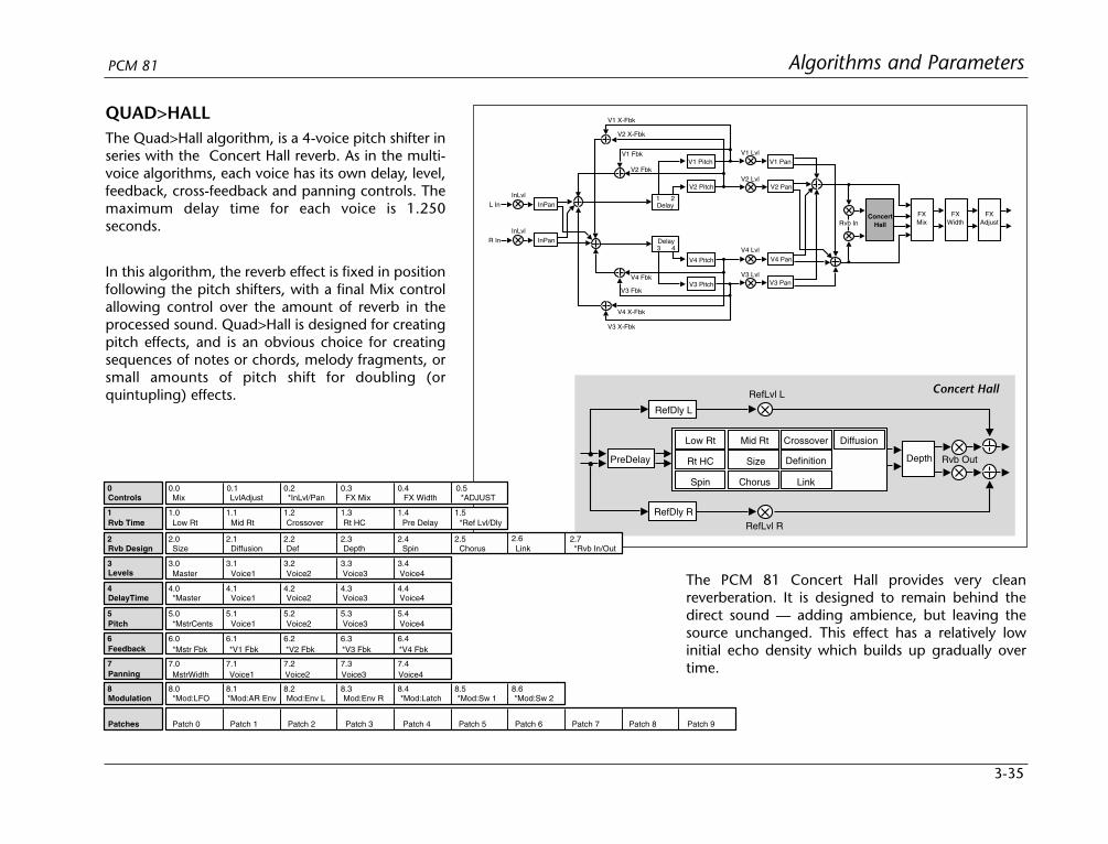
3-35
Algorithms and ParametersPCM 81
QUAD>HALLThe Quad>Hall algorithm, is a 4-voice pitch shifter inseries with the Concert Hall reverb. As in the multi-voice algorithms, each voice has its own delay, level,feedback, cross-feedback and panning controls. Themaximum delay time for each voice is 1.250seconds.
In this algorithm, the reverb effect is fixed in positionfollowing the pitch shifters, with a final Mix controlallowing control over the amount of reverb in theprocessed sound. Quad>Hall is designed for creatingpitch effects, and is an obvious choice for creatingsequences of notes or chords, melody fragments, orsmall amounts of pitch shift for doubling (orquintupling) effects.
RefDly L
RefLvl L
RefDly RRefLvl R
Low Rt Mid Rt
Size Depth
Crossover
Rt HC
Spin Chorus Link
Definition
Diffusion
PreDelay Rvb Out
L In
V2 PanV2 Lvl
V1 Pan
Delay
V1 Lvl
1 2
V2 Fbk
V1 Fbk
V2 X-Fbk
V1 X-Fbk
V4 Pan
V3 Pan
V4 Lvl
V3 Lvl
V2 Pitch
V1 Pitch
3 4Delay
V4 Pitch
V3 Pitch
V3 X-Fbk
V4 X-Fbk
V3 Fbk
V4 Fbk
ConcertHall
FXMix
FXWidth
FXAdjustRvb In
InPanInLvl
R In InPanInLvl
Concert Hall
2 2.0 2.1 2.2 2.3 2.4 2.5
3 3.0 3.1 3.2 3.3 3.4
4 4.0 4.1 4.2 4.3 4.4
5 5.0 5.1 5.2 5.3 5.4
6 6.0 6.1 6.2 6.3 6.4
7 7.0 7.1 7.2 7.3 7.4
0 0.0 0.1 0.2 0.3 0.4
1.5
2.6
1 1.0 1.1 1.2 1.3 1.4
Controls Mix
2.7
LvlAdjust *InLvl/Pan FX Mix *ADJUST
Rvb Time Low Rt Mid Rt Crossover Rt HC Pre Delay *Ref Lvl/Dly
Rvb Design Size Diffusion Def Depth Spin Chorus Link *Rvb In/Out
Levels
DelayTime
Feedback
Patches Patch 0 Patch 1 Patch 2 Patch 3 Patch 4 Patch 5 Patch 6 Patch 7 Patch 8 Patch 9
8 8.0 8.1 8.2 8.3 8.4 8.5 8.6Modulation *Mod:LFO Mod:Env L Mod:Env R *Mod:Latch *Mod:Sw 1 *Mod:Sw 2
Panning
Master Voice1 Voice2 Voice3 Voice4
*Master Voice1 Voice2 Voice3 Voice4
*Mstr Fbk *V1 Fbk *V2 Fbk *V3 Fbk *V4 Fbk
MstrWidth
*Mod:AR Env
Pitch *MstrCents Voice1 Voice2 Voice3 Voice4
Voice1 Voice2 Voice3 Voice4
0.5FX Width
The PCM 81 Concert Hall provides very cleanreverberation. It is designed to remain behind thedirect sound — adding ambience, but leaving thesource unchanged. This effect has a relatively lowinitial echo density which builds up gradually overtime.
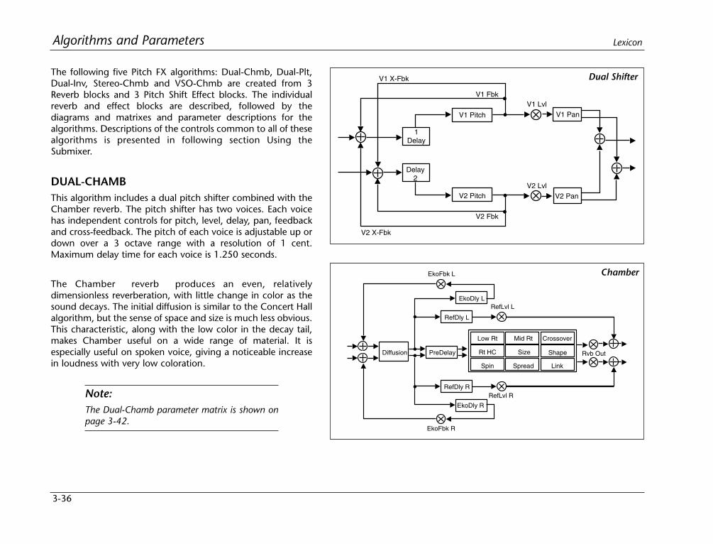
The following five Pitch FX algorithms: Dual-Chmb, Dual-Plt,Dual-Inv, Stereo-Chmb and VSO-Chmb are created from 3Reverb blocks and 3 Pitch Shift Effect blocks. The individualreverb and effect blocks are described, followed by thediagrams and matrixes and parameter descriptions for thealgorithms. Descriptions of the controls common to all of thesealgorithms is presented in following section Using theSubmixer.
DUAL-CHAMBThis algorithm includes a dual pitch shifter combined with theChamber reverb. The pitch shifter has two voices. Each voicehas independent controls for pitch, level, delay, pan, feedbackand cross-feedback. The pitch of each voice is adjustable up ordown over a 3 octave range with a resolution of 1 cent.Maximum delay time for each voice is 1.250 seconds.
The Chamber reverb produces an even, relativelydimensionless reverberation, with little change in color as thesound decays. The initial diffusion is similar to the Concert Hallalgorithm, but the sense of space and size is much less obvious.This characteristic, along with the low color in the decay tail,makes Chamber useful on a wide range of material. It isespecially useful on spoken voice, giving a noticeable increasein loudness with very low coloration.
Note:The Dual-Chamb parameter matrix is shown onpage 3-42.
3-36
Algorithms and Parameters Lexicon
V1 Fbk
Delay1
V2 Pan
V1 Pan
V1 X-Fbk
V2 X-Fbk
V2 Fbk
V1 Pitch
V1 Lvl
V2 LvlV2 Pitch
Delay2
PreDelay
RefDly L
EkoFbk L
EkoDly L
RefDly R
EkoDly R
EkoFbk R
Low Rt Mid Rt
Size Shape
Crossover
Rt HC
Spin Spread Link
RefLvl L
RefLvl R
Diffusion Rvb Out
Dual Shifter
Chamber

3-37
Algorithms and ParametersPCM 81
DUAL-PLTThis algorithm includes a dual pitch shifter combined with thePlate reverb. The pitch shifter has two voices. Each voice hasindependent controls for pitch, level, delay, pan, feedback andcross-feedback. The pitch of each voice is adjustable up ordown over a 3 octave range with a resolution of 1 cent.Maximum delay time for each voice is 1.250 seconds.
The Plate reverb mimics the sound of metal plates, with highinitial diffusion and a relatively bright sound, making it a goodchoice for enhancing any type of percussion.
Note:The Dual-Plt parameter matrix is shown on page3-42.
V1 Fbk
Delay1
V2 Pan
V1 Pan
V1 X-Fbk
V2 X-Fbk
V2 Fbk
V1 Pitch
V1 Lvl
V2 LvlV2 Pitch
Delay2
PreDelay
RefDly L
EkoFbk L
EkoDly L
RefDly R
EkoDly R
EkoFbk R
Low Rt Mid Rt
Size Attack
Spin Link
Crossover
Rt HC
RefLvl L
RefLvl R
Diffusion Rvb Out
Dual Shifter
Plate
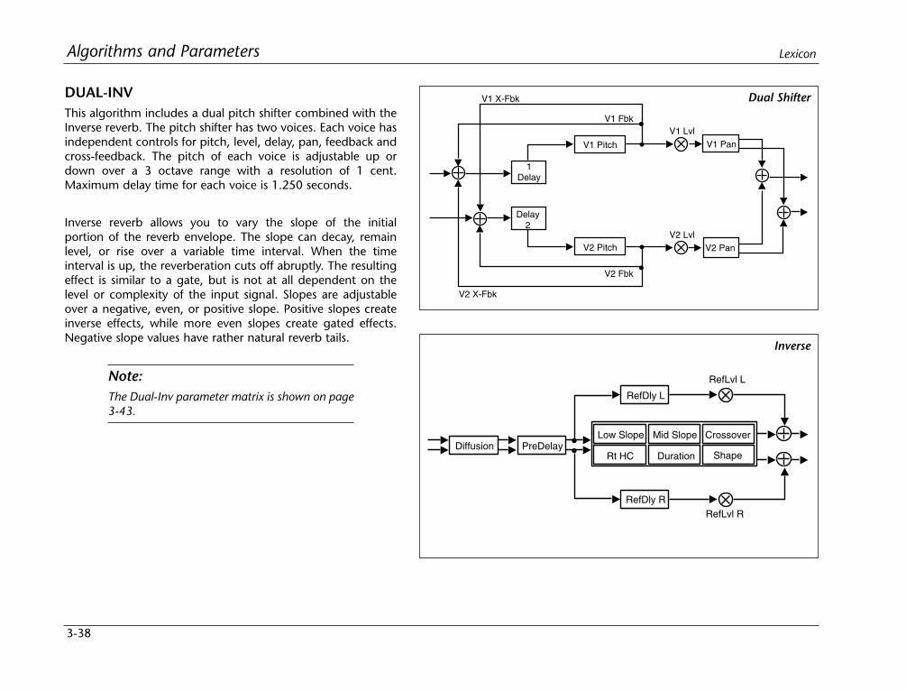
3-38
Algorithms and Parameters Lexicon
DUAL-INVThis algorithm includes a dual pitch shifter combined with theInverse reverb. The pitch shifter has two voices. Each voice hasindependent controls for pitch, level, delay, pan, feedback andcross-feedback. The pitch of each voice is adjustable up ordown over a 3 octave range with a resolution of 1 cent.Maximum delay time for each voice is 1.250 seconds.
Inverse reverb allows you to vary the slope of the initialportion of the reverb envelope. The slope can decay, remainlevel, or rise over a variable time interval. When the timeinterval is up, the reverberation cuts off abruptly. The resultingeffect is similar to a gate, but is not at all dependent on thelevel or complexity of the input signal. Slopes are adjustableover a negative, even, or positive slope. Positive slopes createinverse effects, while more even slopes create gated effects.Negative slope values have rather natural reverb tails.
Note:The Dual-Inv parameter matrix is shown on page3-43.
V1 Fbk
Delay1
V2 Pan
V1 Pan
V1 X-Fbk
V2 X-Fbk
V2 Fbk
V1 Pitch
V1 Lvl
V2 LvlV2 Pitch
Delay2
Diffusion PreDelay
RefDly L
RefDly R
Duration
Low Slope Mid Slope Crossover
Rt HC
RefLvl L
RefLvl R
Shape
Dual Shifter
Inverse
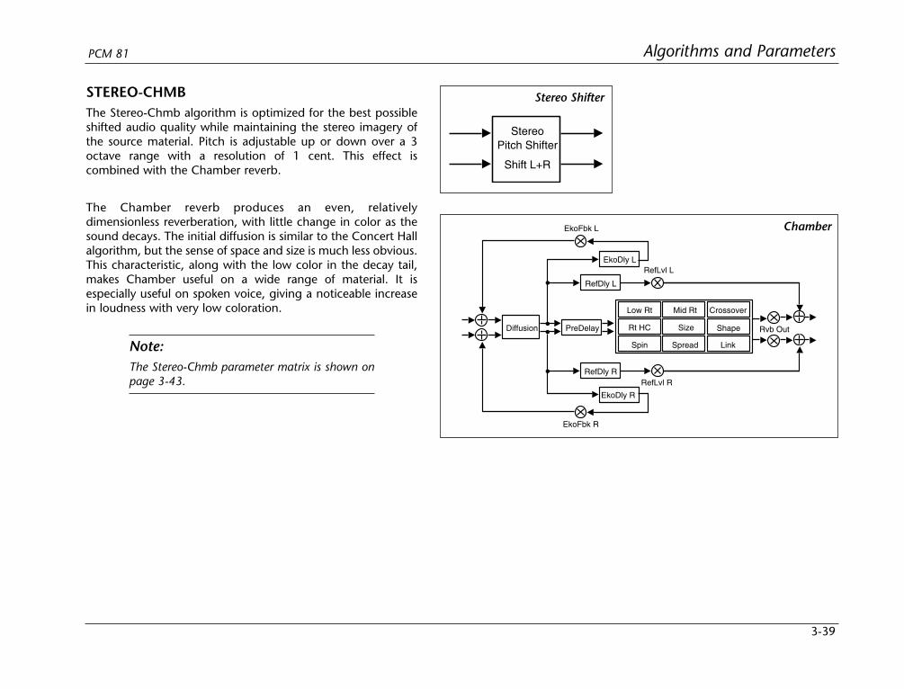
3-39
Algorithms and ParametersPCM 81
STEREO-CHMBThe Stereo-Chmb algorithm is optimized for the best possibleshifted audio quality while maintaining the stereo imagery ofthe source material. Pitch is adjustable up or down over a 3octave range with a resolution of 1 cent. This effect iscombined with the Chamber reverb.
The Chamber reverb produces an even, relativelydimensionless reverberation, with little change in color as thesound decays. The initial diffusion is similar to the Concert Hallalgorithm, but the sense of space and size is much less obvious.This characteristic, along with the low color in the decay tail,makes Chamber useful on a wide range of material. It isespecially useful on spoken voice, giving a noticeable increasein loudness with very low coloration.
Note:The Stereo-Chmb parameter matrix is shown onpage 3-43.
StereoPitch Shifter
Shift L+R
PreDelay
RefDly L
EkoFbk L
EkoDly L
RefDly R
EkoDly R
EkoFbk R
Low Rt Mid Rt
Size Shape
Crossover
Rt HC
Spin Spread Link
RefLvl L
RefLvl R
Diffusion Rvb Out
Stereo Shifter
Chamber
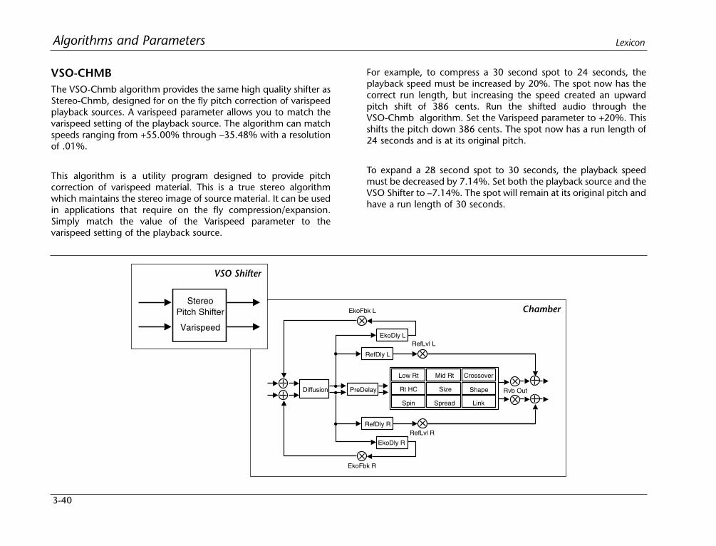
3-40
Algorithms and Parameters Lexicon
VSO-CHMBThe VSO-Chmb algorithm provides the same high quality shifter asStereo-Chmb, designed for on the fly pitch correction of varispeedplayback sources. A varispeed parameter allows you to match thevarispeed setting of the playback source. The algorithm can matchspeeds ranging from +55.00% through –35.48% with a resolutionof .01%.
This algorithm is a utility program designed to provide pitchcorrection of varispeed material. This is a true stereo algorithmwhich maintains the stereo image of source material. It can be usedin applications that require on the fly compression/expansion.Simply match the value of the Varispeed parameter to thevarispeed setting of the playback source.
For example, to compress a 30 second spot to 24 seconds, theplayback speed must be increased by 20%. The spot now has thecorrect run length, but increasing the speed created an upwardpitch shift of 386 cents. Run the shifted audio through theVSO-Chmb algorithm. Set the Varispeed parameter to +20%. Thisshifts the pitch down 386 cents. The spot now has a run length of24 seconds and is at its original pitch.
To expand a 28 second spot to 30 seconds, the playback speedmust be decreased by 7.14%. Set both the playback source and theVSO Shifter to –7.14%. The spot will remain at its original pitch andhave a run length of 30 seconds.
PreDelay
RefDly L
EkoFbk L
EkoDly L
RefDly R
EkoDly R
EkoFbk R
Low Rt Mid Rt
Size Shape
Crossover
Rt HC
Spin Spread Link
RefLvl L
RefLvl R
Diffusion Rvb Out
ChamberStereo
Pitch Shifter
Varispeed
VSO Shifter
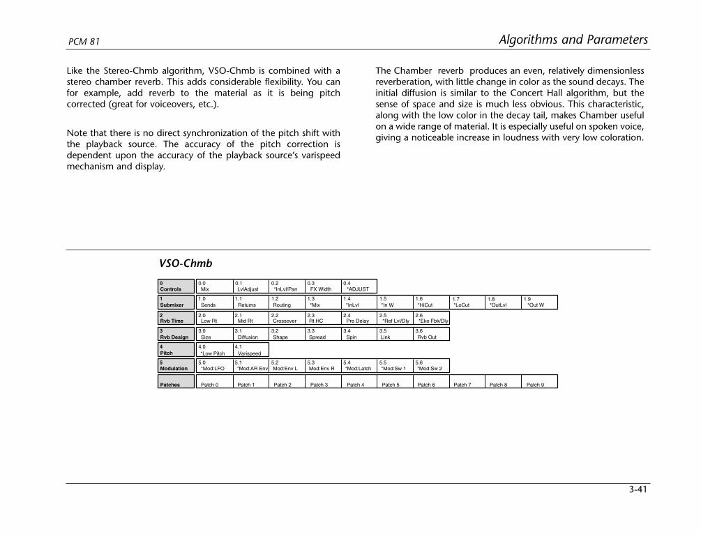
3-41
Algorithms and ParametersPCM 81
2 2.0 2.1 2.2 2.3 2.4 2.5
3 3.0 3.1 3.2 3.3 3.4
4 4.0 4.1
0 0.0 0.1 0.2 0.3 0.4
1.5 1.61 1.0 1.1 1.2 1.3 1.4
Controls Mix
1.7 1.8 1.9
3.5 3.6
LvlAdjust *InLvl/Pan FX Width *ADJUST
Submixer Sends Returns Routing *Mix *In W *HiCut *LoCut *OutLvl *Out W*InLvl
Rvb Time Low Rt Mid Rt Crossover Rt HC Pre Delay *Ref Lvl/Dly
Rvb Design Size Diffusion Shape Spread Spin Link Rvb Out
Patches Patch 0 Patch 1 Patch 2 Patch 3 Patch 4 Patch 5 Patch 6 Patch 7 Patch 8 Patch 9
5 5.0 5.1 5.2 5.3 5.4 5.5 5.6Modulation *Mod:LFO *Mod:AR Env Mod:Env L Mod:Env R *Mod:Latch *Mod:Sw 1 *Mod:Sw 2
Pitch *Low Pitch Varispeed
2.6*Eko Fbk/Dly
VSO-Chmb
Like the Stereo-Chmb algorithm, VSO-Chmb is combined with astereo chamber reverb. This adds considerable flexibility. You canfor example, add reverb to the material as it is being pitchcorrected (great for voiceovers, etc.).
Note that there is no direct synchronization of the pitch shift withthe playback source. The accuracy of the pitch correction isdependent upon the accuracy of the playback source’s varispeedmechanism and display.
The Chamber reverb produces an even, relatively dimensionlessreverberation, with little change in color as the sound decays. Theinitial diffusion is similar to the Concert Hall algorithm, but thesense of space and size is much less obvious. This characteristic,along with the low color in the decay tail, makes Chamber usefulon a wide range of material. It is especially useful on spoken voice,giving a noticeable increase in loudness with very low coloration.

3-42
Algorithms and Parameters Lexicon
2 2.0 2.1 2.2 2.3 2.4 2.5
3 3.0 3.1 3.2 3.3 3.4
4 4.0 4.1 4.2
5 5.0 5.1 5.2
6 6.0 6.1 6.2
7 7.0 7.1 7.2
0 0.0 0.1 0.2 0.3 0.4
1.5 1.61 1.0 1.1 1.2 1.3 1.4
Controls Mix
1.7 1.8 1.9
3.5
LvlAdjust *InLvl/Pan FX Width *ADJUST
Submixer Sends Returns Routing *Mix *In W *HiCut *LoCut *OutLvl *Out W*InLvl
Rvb Time Low Rt Mid Rt Crossover Rt HC Pre Delay *Ref Lvl/Dly
Rvb Design Size Diffusion Attack Spin Link Rvb Out
Levels
Pitch
Feedback
Patches Patch 0 Patch 1 Patch 2 Patch 3 Patch 4 Patch 5 Patch 6 Patch 7 Patch 8 Patch 9
9 9.0 9.1 9.2 9.3 9.4 9.5 9.6Modulation *Mod:LFO *Mod:AR Env Mod:Env L Mod:Env R *Mod:Latch *Mod:Sw 1 *Mod:Sw 2
8 8.0 8.1 8.2Panning
Master Voice1 Voice2
*MstrCents Voice1 Voice2
*Mstr Fbk *V1 Fbk *V2 Fbk
MstrWidth Voice 1 Voice 2
2.6*Eko Fbk/Dly
DelayTime *Master Voice1 Voice2
Dual-Plt
2 2.0 2.1 2.2 2.3 2.4 2.5
3 3.0 3.1 3.2 3.3 3.4
4 4.0 4.1 4.2
5 5.0 5.1 5.2
6 6.0 6.1 6.2
7 7.0 7.1 7.2
0 0.0 0.1 0.2 0.3 0.4
1.5 1.61 1.0 1.1 1.2 1.3 1.4
Controls Mix
1.7 1.8 1.9
3.5 3.6
LvlAdjust *InLvl/Pan FX Width *ADJUST
Submixer Sends Returns Routing *Mix *In W *HiCut *LoCut *OutLvl *Out W*InLvl
Rvb Time Low Rt Mid Rt Crossover Rt HC Pre Delay *Ref Lvl/Dly
Rvb Design Size Diffusion Shape Spread Spin Link Rvb Out
Levels
Pitch
Feedback
Patches Patch 0 Patch 1 Patch 2 Patch 3 Patch 4 Patch 5 Patch 6 Patch 7 Patch 8 Patch 9
9 9.0 9.1 9.2 9.3 9.4 9.5 9.6Modulation *Mod:LFO *Mod:AR Env Mod:Env L Mod:Env R *Mod:Latch *Mod:Sw 1 *Mod:Sw 2
8 8.0 8.1 8.2Panning
Master Voice1 Voice2
*MstrCents Voice1 Voice2
*Mstr Fbk *V1 Fbk *V2 Fbk
MstrWidth Voice1 Voice2
2.6*Eko Fbk/Dly
DelayTime *Master Voice1 Voice2
Dual-Chamb
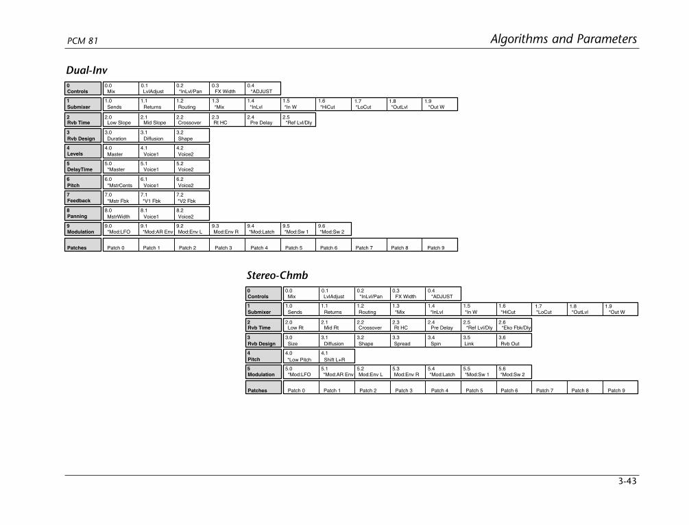
3-43
Algorithms and ParametersPCM 81
2 2.0 2.1 2.2 2.3 2.4 2.5
3 3.0 3.1 3.2
4 4.0 4.1 4.2
5 5.0 5.1 5.2
6 6.0 6.1 6.2
7 7.0 7.1 7.2
0 0.0 0.1 0.2 0.3 0.4
1.5 1.61 1.0 1.1 1.2 1.3 1.4
Controls Mix
1.7 1.8 1.9
LvlAdjust *InLvl/Pan FX Width *ADJUST
Submixer Sends Returns Routing *Mix *In W *HiCut *LoCut *OutLvl *Out W*InLvl
Rvb Time Low Slope Mid Slope Crossover Rt HC Pre Delay *Ref Lvl/Dly
Rvb Design Duration Diffusion Shape
Levels
Pitch
Feedback
Patches Patch 0 Patch 1 Patch 2 Patch 3 Patch 4 Patch 5 Patch 6 Patch 7 Patch 8 Patch 9
9 9.0 9.1 9.2 9.3 9.4 9.5 9.6Modulation *Mod:LFO *Mod:AR Env Mod:Env L Mod:Env R *Mod:Latch *Mod:Sw 1 *Mod:Sw 2
8 8.0 8.1 8.2Panning
Master Voice1 Voice2
*MstrCents Voice1 Voice2
*Mstr Fbk *V1 Fbk *V2 Fbk
MstrWidth Voice1 Voice2
DelayTime *Master Voice1 Voice2
Dual-Inv
2 2.0 2.1 2.2 2.3 2.4 2.5
3 3.0 3.1 3.2 3.3 3.4
4 4.0 4.1
0 0.0 0.1 0.2 0.3 0.4
1.5 1.61 1.0 1.1 1.2 1.3 1.4
Controls Mix
1.7 1.8 1.9
3.5 3.6
LvlAdjust *InLvl/Pan FX Width *ADJUST
Submixer Sends Returns Routing *Mix *In W *HiCut *LoCut *OutLvl *Out W*InLvl
Rvb Time Low Rt Mid Rt Crossover Rt HC Pre Delay *Ref Lvl/Dly
Rvb Design Size Diffusion Shape Spread Spin Link Rvb Out
Patches Patch 0 Patch 1 Patch 2 Patch 3 Patch 4 Patch 5 Patch 6 Patch 7 Patch 8 Patch 9
5 5.0 5.1 5.2 5.3 5.4 5.5 5.6Modulation *Mod:LFO *Mod:AR Env Mod:Env L Mod:Env R *Mod:Latch *Mod:Sw 1 *Mod:Sw 2
Pitch *Low Pitch Shift L+R
2.6*Eko Fbk/Dly
Stereo-Chmb
THE PITCH PARAMETERS
MstrCents
This is a master pitch offset control for all voices. The value dialedin here will be added to all voices. This control allows you totranspose pitch voices while keeping the relative interval(s)between them constant.
MstrScale
This is a master pitch scaling control for all voices. The value ofeach pitch voice is multiplied by this percentage. This controlallows you to shrink or enlarge the relative interval(s) between allvoices.
Low Pitch
This parameter allows you to optimize the pitch shifter for the lowfrequency content of the input material. Use low values whenshifting single note material with low frequencies, polyphonicsources or full bandwidth material. Note that the lower this value,the longer the pitch shifted material is delayed. At the lowestsetting, the amount of delay is about 42ms. At the highest settingit is about 12ms.
Use this parameter to minimize the amount of delay inherent in thepitch shift process. If the maximum delay of about 40ms is not aproblem, you can simply set this value to its lowest setting. Tominimize the delay for single note pitch shifting, set it to a valuethat matches the pitch of the lowest note in the input material. Ifyou are pitch shifting polyphonic input material you may getbetter results by setting the value lower than the lowest note in theinput material.
Lowest note of some typical sources:
• Piano A0 • Tenor Sax Bb2
• Bass guitar E1 • Vocal: bass Eb2
• Guitar E2 • Vocal: baritone Ab2
• Trombone F2 • Vocal: tenor Db3
Splice
This parameter allows you to change the number of millisecondsused to crossfade the splices that are constantly occurringwhenever pitch is shifted. For most material a value of 4ms isappropriate. Higher values will produce longer/smoothercrossfades, but the intelligibility of transients and high frequencycontent may be affected. Lower values will reproduce transientsmore accurately and have more high frequency content, but thesplices may be more audible.
GldResp
This parameter is similar to the GldResp parameter in the MasterDelay parameter of the delay and reverb algorithms. It sets thepitch shifters responsiveness to modulation by internal controllers(LFO, AR, etc.) and MIDI controllers (AfterTouch, Velocity, etc.). Ithas no effect on the quality of the pitch shifted sound. At thehighest setting (100) the pitch will track the modulation sourcevery closely. At lower settings, the pitch will lag behind themodulation source. Use lower settings to smooth out modulationeffects.
3-44
Algorithms and Parameters Lexicon
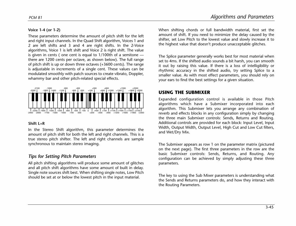
3-45
Algorithms and ParametersPCM 81
Voice 1-4 (or 1-2)
These parameters determine the amount of pitch shift for the leftand right input channels. In the Quad Shift algorithm, Voices 1 and2 are left shifts and 3 and 4 are right shifts. In the 2-Voicealgorithms, Voice 1 is left shift and Voice 2 is right shift. The valueis given in cents ( one cent is equal to 1/100th of a semitone —there are 1200 cents per octave, as shown below). The full rangeof pitch shift is up or down three octaves (+3600 cents). The rangeis adjustable in increments of a single cent. These values can bemodulated smoothly with patch sources to create vibrato, Doppler,whammy bar and other pitch-related special effects.
0
+100+300
+200+400
+500
+600+800
+700+900
+1000
+1100+1200
+1300+1500
+1400
+1800+2000
+2200
+1600+1700
+1900+2100
+2300-300-100
-200-400
-500
-600-900
-1100
-700-800
-1000-1200
-1300
-1400-1600
-1800
-1500-1700
-1900-2000
-2100-2300
-2200-2400
Shift L+R
In the Stereo Shift algorithm, this parameter determines theamount of pitch shift for both the left and right channels. This is atrue stereo pitch shifter. The left and right channels are samplesynchronous to maintain stereo imaging.
Tips for Setting Pitch ParametersAll pitch shifting algorithms will produce some amount of glitchesand all pitch shift algorithms have some amount of built in delay.Single note sources shift best. When shifting single notes, Low Pitchshould be set at or below the lowest pitch in the input material.
When shifting chords or full bandwidth material, first set theamount of shift. If you need to minimize the delay caused by theshifter, set Low Pitch to the lowest value and slowly increase it tothe highest value that doesn’t produce unacceptable glitches.
The Splice parameter generally works best for most material whenset to 4ms. If the shifted audio sounds a bit harsh, you can smoothit out by raising this value. If there is a loss of intelligibility orrhythmic accuracy in the shifted audio, try setting Splice to asmaller value. As with most effect parameters, you should rely onyour ears to find the best settings for a given situation.
USING THE SUBMIXERExpanded configuration control is available in those Pitchalgorithms which have a Submixer incorporated into eachalgorithm. This Submixer lets you arrange any combination ofreverb and effects blocks in any configuration simply by changingthe three main Submixer controls: Sends, Returns and Routing.Additional controls are provided for each block: Input Level, InputWidth, Output Width, Output Level, High Cut and Low Cut filters,and Wet/Dry Mix.
The Submixer appears as row 1 on the parameter matrix (picturedon the next page). The first three parameters in the row are thebasic Submixer controls: Sends, Returns, and Routing. Anyconfiguration can be achieved by simply adjusting these threeparameters.
The key to using the Sub Mixer parameters is understanding whatthe Sends and Returns parameters do, and how they interact withthe Routing Parameters.
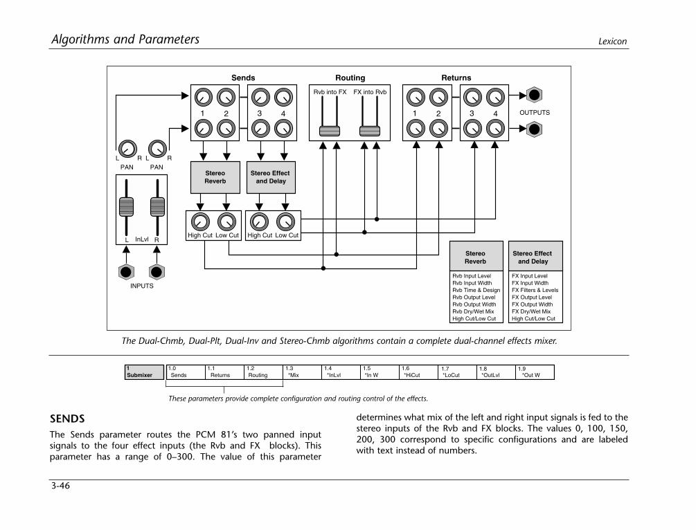
SENDSThe Sends parameter routes the PCM 81’s two panned inputsignals to the four effect inputs (the Rvb and FX blocks). Thisparameter has a range of 0–300. The value of this parameter
3-46
Algorithms and Parameters Lexicon
Sends ReturnsRouting
1 2
PAN PANL R L R
3 4
Stereo Effect and Delay
StereoReverb
Rvb into FX FX into Rvb
1 2 3 4
INPUTS
OUTPUTS
StereoReverb
Rvb Input LevelRvb Input WidthRvb Time & DesignRvb Output LevelRvb Output WidthRvb Dry/Wet MixHigh Cut/Low Cut
High Cut
FX Input LevelFX Input WidthFX Filters & LevelsFX Output LevelFX Output WidthFX Dry/Wet MixHigh Cut/Low Cut
Stereo Effect and Delay
Low Cut High Cut Low CutL RInLvl
1.5 1.61 1.0 1.1 1.2 1.3 1.4 1.7 1.8 1.9Submixer Sends Returns Routing *Mix *In W *HiCut *LoCut *OutLvl *Out W*InLvl
These parameters provide complete configuration and routing control of the effects.
The Dual-Chmb, Dual-Plt, Dual-Inv and Stereo-Chmb algorithms contain a complete dual-channel effects mixer.
determines what mix of the left and right input signals is fed to thestereo inputs of the Rvb and FX blocks. The values 0, 100, 150,200, 300 correspond to specific configurations and are labeledwith text instead of numbers.

3-47
Algorithms and ParametersPCM 81
Sends Value Rvb Sends FX Sends
Stereo (0) L to left Rvb In L to left FX In
R to right Rvb In R to right FX In
L=Rvb, R=FX (100) L to left Rvb In R to left FX In
L to right Rvb In R to right FX In
Mono (150) L+R to left Rvb In L+R to left FX In
L+R to right Rvb In L+R to right FX In
L=FX, R=Rvb (200) R to left Rvb In L to left FX In
R to right Rvb In L to right FX In
Stereo (300) L to left Rvb In L to left FX In
R to right Rvb In R to right FX In
RETURNSThe Returns parameter routes the four effects outputs to the PCM81’s stereo outputs. This parameter has a range of 0–300. Thevalue of this parameter determines what mix of the stereo Rvb andFX outputs is fed to the PCM 81’s stereo outputs.The values 0, 100,150, 200, 300 correspond to specific configurations and arelabeled with text instead of numbers.
Returns Value Rvb Returns FX Returns
Stereo (0) left Rvb Out to L left FX Out to L
right Rvb Out to R right FX Out to R
Rvb=L, FX=R (100) left Rvb Out to L left FX Out to R
right Rvb Out to L right FX Out to R
Returns Value Rvb Returns FX Returns
Mono (150) left + right Rvb Out to L left + right FXOut to L
left + right Rvb Out to R left + right FXOut to R
FX=L, Rvb=R (200) left Rvb Out to R left FX Out to L
right Rvb Out to R right FX Out to L
Stereo (300) left Rvb Out to L left FX Out to L
right Rvb Out to R right FX Out to R
ROUTINGThe Routing parameter provides continuously variable control ofthe FX and Rvb effect routing: Rvb and FX in parallel, Rvb into FX(series) and FX into Rvb (reverse series). This parameter has a rangeof 0–400. The value of this parameter determines the routing/ordering of the stereo Rvb and FX effects. The values 0, 100, 150,200, 300, 400 correspond to specific configurations and arelabeled with text instead of numbers.
Routing Value Effects Routing
Parallel (0) Rvb and FX are parallel
Rvb into FX (100) Rvb outputs into FX inputs (series 1)
Parallel (200) Rvb and FX are parallel
FX into Rvb (300) FX outputs into Rvb inputs (series 2)
Parallel (400) Rvb and FX are parallel
Note that the routing value takes precedence over the Sends andReturns values. For example, if Routing is set to Rvb into FX (100),no input signal is routed directly to the FX inputs — and the Rvboutputs aren’t sent directly to the PCM 81’s main outputs.

3-48
Algorithms and Parameters Lexicon
USEFUL CONFIGURATIONSIt is possible to arrange the stereo Rvb and FX inputs and out-puts into a variety of useful configurations by simply adjustingthe Sends, Returns and Routing parameters. The followingillustrations show several of these configurations. Each illustra-tion contains a block diagram showing signal flow through theSubmixer, and the displayed values for the Sends, Returns, andRouting parameters that will produce the configuration.
Stereo Series 1• The main stereo inputs are sent into the Rvb block.
• The stereo output of the Rvb block is sent into the stereoinputs of the FX block.
• The stereo output of the FX block is sent to the main leftand right outputs.
Stereo Series 2• The main stereo inputs are sent into the FX block.
• The stereo output of the FX block is sent into the stereoinputs of the Rvb block.
• The stereo output of the Rvb block is sent to the main leftand right outputs.
Rvb Mix
Rvb Mix
FX Mix
FX Mix
Submixer SendsStereo
Submixer ReturnsStereo
Submixer RoutingRvb into FX
Rvb FXL In
R In
L Out
R Out
Submixer Sends
1.0 0 Stereo
Submixer Returns
1.1 0 Stereo
Submixer Routing
1.2 100 Rvb into FX
Stereo Series 1
Submixer Sends
1.0 0 Stereo
Submixer Returns
1.1 0 Stereo
Submixer Routing
1.2 300 FX into Rvb
FX Mix
FX Mix
Rvb Mix
Rvb Mix
Submixer SendsStereo
Submixer ReturnsStereo
Submixer RoutingFX into Rvb
FX RvbL In
R In
L Out
R Out
Stereo Series 2
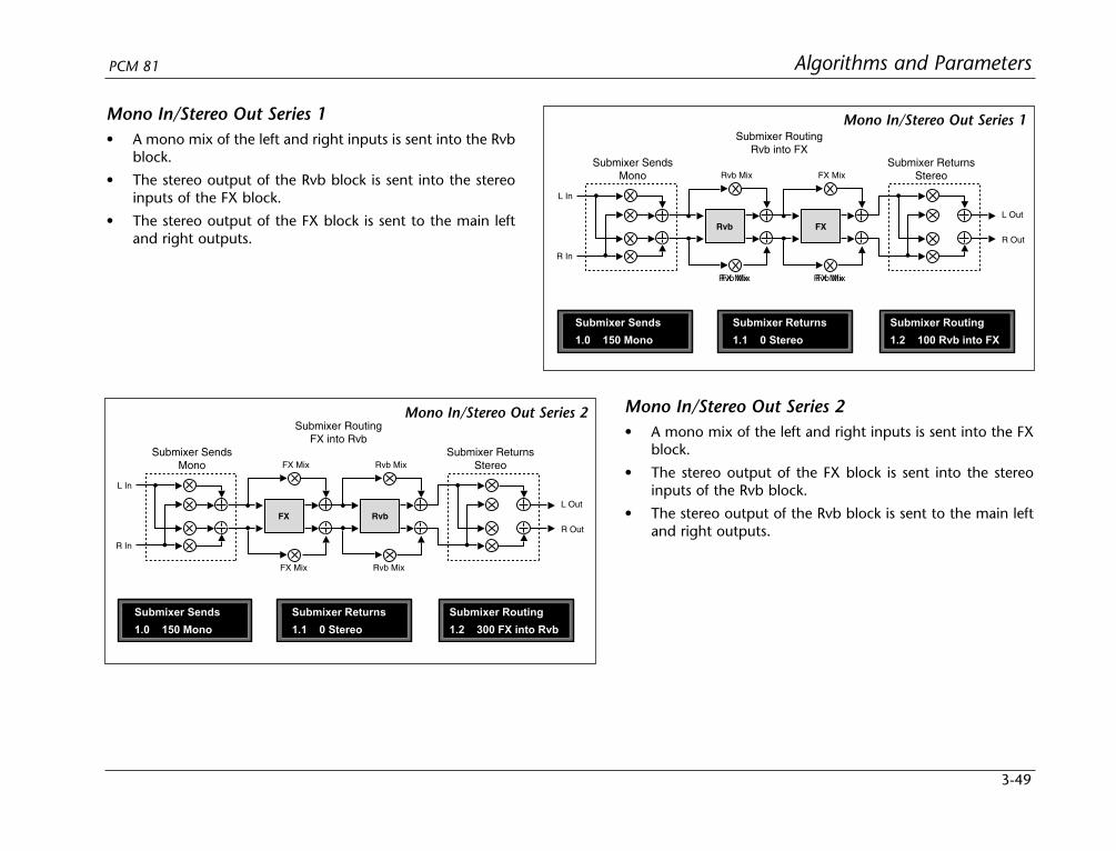
3-49
Algorithms and ParametersPCM 81
Mono In/Stereo Out Series 1• A mono mix of the left and right inputs is sent into the Rvb
block.
• The stereo output of the Rvb block is sent into the stereoinputs of the FX block.
• The stereo output of the FX block is sent to the main leftand right outputs.
Mono In/Stereo Out Series 2• A mono mix of the left and right inputs is sent into the FX
block.
• The stereo output of the FX block is sent into the stereoinputs of the Rvb block.
• The stereo output of the Rvb block is sent to the main leftand right outputs.
Submixer Sends
1.0 150 Mono
Submixer Returns
1.1 0 Stereo
Submixer Routing
1.2 100 Rvb into FX
FX Mix Rvb Mix
Rvb Mix
Rvb Mix
FX Mix
FX Mix
Submixer SendsMono
Submixer ReturnsStereo
Submixer RoutingRvb into FX
Rvb FX
L In
R In
L Out
R Out
Mono In/Stereo Out Series 1
Submixer Sends
1.0 150 Mono
Submixer Returns
1.1 0 Stereo
Submixer Routing
1.2 300 FX into Rvb
FX Mix
FX Mix
Rvb Mix
Rvb Mix
Submixer SendsMono
Submixer ReturnsStereo
Submixer RoutingFX into Rvb
RvbFX
L In
R In
L Out
R Out
Mono In/Stereo Out Series 2

3-50
Algorithms and Parameters Lexicon
Stereo Parallel• The Rvb and FX blocks process the left and right
inputs independently.
• The stereo outputs of both the Rvb and FX blocks arecombined at the main outputs.
Submixer Sends
1.0 150 Mono
Submixer Returns
1.1 0 Stereo
Submixer Routing
1.2 0 Parallel
Rvb Mix
Rvb Mix
Submixer SendsMono
Submixer ReturnsStereo
Submixer RoutingParallel
Rvb
FX
FX Mix
FX Mix
L In
R In
L Out
R Out
Mono In/StereoOut Parallel
Submixer Sends
1.0 0 Stereo
Submixer Returns
1.1 0 Stereo
Submixer Routing
1.2 0 Parallel
Rvb Mix
Rvb Mix
Submixer SendsStereo
Submixer ReturnsStereo
Submixer RoutingParallel
Rvb
FX
FX Mix
FX Mix
L In
R In
L Out
R Out
Stereo Parallel
Mono In/Stereo Out Parallel• The Rvb and FX blocks each independently process a
mono mix of the left and right inputs.
• The stereo outputs of both the Rvb and FX blocks arecombined at the main outputs.

3-51
Algorithms and ParametersPCM 81
Dual Mono In/Stereo Out• The Rvb block processes only the left input as a
mono signal, and the FX block processes only theright input as a mono signal.
• The stereo outputs of both the Rvb and FX blocks arecombined at the main outputs.
Dual Mono In/Mono Out• The Rvb block processes only the left input as a
mono signal, and the FX block processes only theright input as a mono signal.
• A mono mix of the Rvb block output is sent to theleft main output. A mono mix of the FX output issent to the right main output.
Submixer Sends
1.0 100 L=Rvb, R=FX
Submixer Returns
1.1 100 Rvb=L, FX=R
Submixer Routing
1.2 0 Parallel
Rvb Mix
Rvb Mix
Submixer SendsL=FX, R=Rvb
Submixer ReturnsFX=L, Rvb=R
Submixer RoutingParallel
Rvb
FX
FX Mix
FX Mix
L In
R In
L Out
R Out
Dual Mono In/Mono Out Submixer Sends
1.0 100 L=Rvb, R=FX
Submixer Returns
1.1 0 Stereo
Submixer Routing
1.2 0 Parallel
Rvb Mix
Rvb Mix
Submixer SendsMono
Submixer ReturnsStereo
Submixer RoutingParallel
Rvb
FX
FX Mix
FX Mix
R In
L In
L Out
R Out
Dual Mono In/Stereo Out
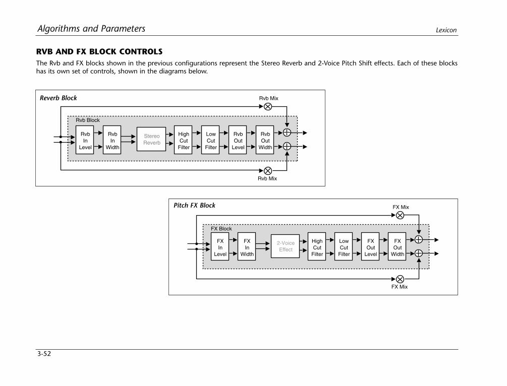
3-52
Algorithms and Parameters Lexicon
RVB AND FX BLOCK CONTROLSThe Rvb and FX blocks shown in the previous configurations represent the Stereo Reverb and 2-Voice Pitch Shift effects. Each of these blockshas its own set of controls, shown in the diagrams below.
Rvb Mix
Rvb Mix
RvbOut
Width
StereoReverb
RvbOut
Level
LowCut
Filter
HighCut
Filter
RvbIn
Width
RvbIn
Level
Rvb Block
FX Mix
FX Mix
FXOut
Width
2-VoiceEffect
FXOut
Level
LowCut
Filter
HighCut
Filter
FXIn
Width
FXIn
Level
FX Block
Reverb Block
Pitch FX Block
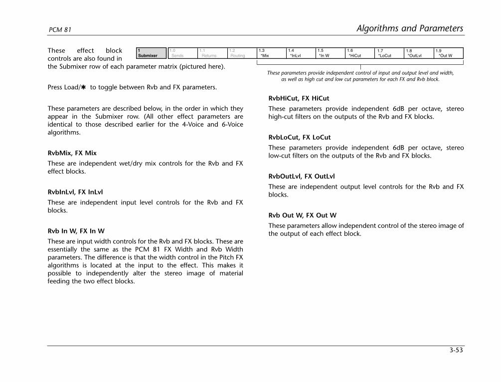
3-53
Algorithms and ParametersPCM 81
These effect blockcontrols are also found inthe Submixer row of each parameter matrix (pictured here).
Press Load/ to toggle between Rvb and FX parameters.
These parameters are described below, in the order in which theyappear in the Submixer row. (All other effect parameters areidentical to those described earlier for the 4-Voice and 6-Voicealgorithms.
RvbMix, FX Mix
These are independent wet/dry mix controls for the Rvb and FXeffect blocks.
RvbInLvl, FX InLvl
These are independent input level controls for the Rvb and FXblocks.
Rvb In W, FX In W
These are input width controls for the Rvb and FX blocks. These areessentially the same as the PCM 81 FX Width and Rvb Widthparameters. The difference is that the width control in the Pitch FXalgorithms is located at the input to the effect. This makes itpossible to independently alter the stereo image of materialfeeding the two effect blocks.
1.5 1.61 1.0 1.1 1.2 1.3 1.4 1.7 1.8 1.9Submixer Sends Returns Routing *Mix *In W *HiCut *LoCut *OutLvl *Out W*InLvl
These parameters provide independent control of input and output level and width,as well as high cut and low cut parameters for each FX and Rvb block.
RvbHiCut, FX HiCut
These parameters provide independent 6dB per octave, stereohigh-cut filters on the outputs of the Rvb and FX blocks.
RvbLoCut, FX LoCut
These parameters provide independent 6dB per octave, stereolow-cut filters on the outputs of the Rvb and FX blocks.
RvbOutLvl, FX OutLvl
These are independent output level controls for the Rvb and FXblocks.
Rvb Out W, FX Out W
These parameters allow independent control of the stereo image ofthe output of each effect block.
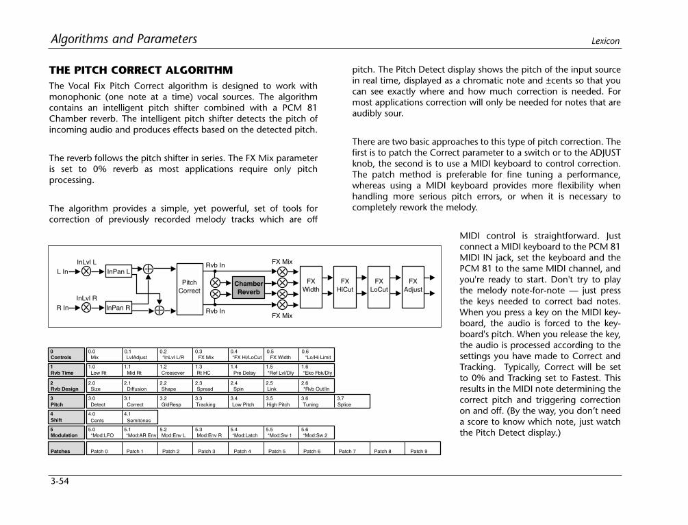
3-54
Algorithms and Parameters Lexicon
THE PITCH CORRECT ALGORITHMThe Vocal Fix Pitch Correct algorithm is designed to work withmonophonic (one note at a time) vocal sources. The algorithmcontains an intelligent pitch shifter combined with a PCM 81Chamber reverb. The intelligent pitch shifter detects the pitch ofincoming audio and produces effects based on the detected pitch.
The reverb follows the pitch shifter in series. The FX Mix parameteris set to 0% reverb as most applications require only pitchprocessing.
The algorithm provides a simple, yet powerful, set of tools forcorrection of previously recorded melody tracks which are off
pitch. The Pitch Detect display shows the pitch of the input sourcein real time, displayed as a chromatic note and ±cents so that youcan see exactly where and how much correction is needed. Formost applications correction will only be needed for notes that areaudibly sour.
There are two basic approaches to this type of pitch correction. Thefirst is to patch the Correct parameter to a switch or to the ADJUSTknob, the second is to use a MIDI keyboard to control correction.The patch method is preferable for fine tuning a performance,whereas using a MIDI keyboard provides more flexibility whenhandling more serious pitch errors, or when it is necessary tocompletely rework the melody.
MIDI control is straightforward. Justconnect a MIDI keyboard to the PCM 81MIDI IN jack, set the keyboard and thePCM 81 to the same MIDI channel, andyou're ready to start. Don't try to playthe melody note-for-note — just pressthe keys needed to correct bad notes.When you press a key on the MIDI key-board, the audio is forced to the key-board's pitch. When you release the key,the audio is processed according to thesettings you have made to Correct andTracking. Typically, Correct will be setto 0% and Tracking set to Fastest. Thisresults in the MIDI note determining thecorrect pitch and triggering correctionon and off. (By the way, you don’t needa score to know which note, just watchthe Pitch Detect display.)
L In
ChamberReverb
FXWidth
FXHiCut
InLvl L
R InInLvl R
FX Mix
FX Mix
FXLoCut
FXAdjust
InPan L
InPan R
PitchCorrect
Rvb In
Rvb In
2 2.0 2.1 2.2 2.3 2.4 2.5
3 3.0 3.1 3.2 3.3 3.4
4 4.0 4.1
0 0.0 0.1 0.2 0.3 0.4
1.5 1.61 1.0 1.1 1.2 1.3 1.4
Controls Mix
3.5 3.6
LvlAdjust *InLvl L/R FX Mix *FX Hi/LoCut
Rvb Time Low Rt Mid Rt Crossover Rt HC Pre Delay *Ref Lvl/Dly
Rvb Design Size Diffusion Shape Spread Spin Link *Rvb Out/In
Shift
Pitch
Patches Patch 0 Patch 1 Patch 2 Patch 3 Patch 4 Patch 5 Patch 6 Patch 7 Patch 8 Patch 9
5 5.0 5.1 5.2 5.3 5.4 5.5 5.6Modulation *Mod:LFO *Mod:AR Env Mod:Env L Mod:Env R *Mod:Latch *Mod:Sw 1 *Mod:Sw 2
Cents Semitones
Detect Correct GldResp
2.6
*Eko Fbk/Dly
0.5FX Width
0.6*Lo/Hi Limit
3.7Tracking Low Pitch High Pitch Tuning Splice
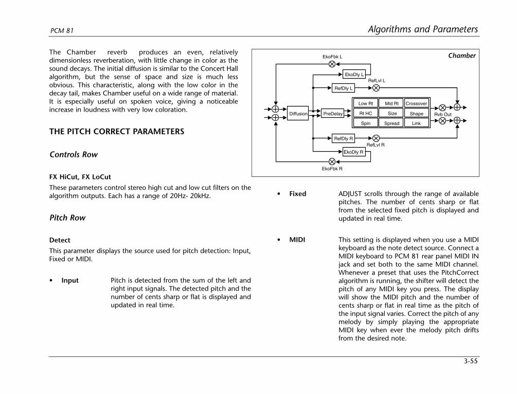
3-55
Algorithms and ParametersPCM 81
The Chamber reverb produces an even, relativelydimensionless reverberation, with little change in color as thesound decays. The initial diffusion is similar to the Concert Hallalgorithm, but the sense of space and size is much lessobvious. This characteristic, along with the low color in thedecay tail, makes Chamber useful on a wide range of material.It is especially useful on spoken voice, giving a noticeableincrease in loudness with very low coloration.
THE PITCH CORRECT PARAMETERS
Controls Row
FX HiCut, FX LoCut
These parameters control stereo high cut and low cut filters on thealgorithm outputs. Each has a range of 20Hz- 20kHz.
Pitch Row
Detect
This parameter displays the source used for pitch detection: Input,Fixed or MIDI.
• Input Pitch is detected from the sum of the left andright input signals. The detected pitch and thenumber of cents sharp or flat is displayed andupdated in real time.
PreDelay
RefDly L
EkoFbk L
EkoDly L
RefDly R
EkoDly R
EkoFbk R
Low Rt Mid Rt
Size Shape
Crossover
Rt HC
Spin Spread Link
RefLvl L
RefLvl R
Diffusion Rvb Out
Chamber
• Fixed ADJUST scrolls through the range of availablepitches. The number of cents sharp or flatfrom the selected fixed pitch is displayed andupdated in real time.
• MIDI This setting is displayed when you use a MIDIkeyboard as the note detect source. Connect aMIDI keyboard to PCM 81 rear panel MIDI INjack and set both to the same MIDI channel.Whenever a preset that uses the PitchCorrectalgorithm is running, the shifter will detect thepitch of any MIDI key you press. The displaywill show the MIDI pitch and the number ofcents sharp or flat in real time as the pitch ofthe input signal varies. Correct the pitch of anymelody by simply playing the appropriateMIDI key when ever the melody pitch driftsfrom the desired note.

3-56
Algorithms and Parameters Lexicon
Correction
This parameter lets you control the amount of off-pitch correction(0-100%) applied. When set to 0, no correction is applied. Whenset to 100%, notes are shifted as close as possible to the frequencyof the detected pitch (or to the frequency of harmonies of thedetected pitch).
GldResp
This parameter is similar to the GldResp parameter found in theMaster Delay parameter of several PCM 81 delay and reverbalgorithms. It sets the pitch shifter’s responsiveness to the pitchdetect source and also to modulation by internal controllers (LFO,AR etc.) and MIDI controllers (aftertouch, velocity, etc.) At thehighest setting (100), the pitch will track the detect source veryclosely. At lower settings, the pitch will lag behind the modulationsource. A setting of about 50 generally yields good results fortracking vocals.
Tracking
This parameter controls how quickly (accurately) the pitch detectorwill follow pitch changes in the detect source. This control can beset to Fastest, Fast, Moderate, Slow or Hold.
• Fastest This is generally the most useful setting as itprovides accurate tracking as well as goodhandling of vibrato or pitch bends.
• Fast, These settings are useful for special effects.Moderate, This setting freezes at the last detected pitch,and Slow effectively turning any melody into a pedalHold tone.
Low Pitch and High Pitch
These controls allow you to set a range of pitches to be detected.This is very useful with source material that has extraneous noise,for example, a vocal track which contains some headphone leakagepicked up by the vocal mike. If Low and High Pitch are set tobracket only the vocal frequencies, there will be no glitches causedby the shifter detecting headphone material outside the vocalrange.
Note that Low Pitch also affects the amount of time that the pitchshifted material is delayed. At the lowest setting, the amount ofdelay is about 60ms. At the highest setting it is about 20ms.
For reference, a list of the lowest and highest pitches of sometypical sources is shown below.
vocal: bass Eb2 to -Eb4
vocal: baritone Ab2 to -Ab4
vocal: tenor C3 to -C5
vocal: alto F3 to -F5
vocal: soprano C4 to -C6
Tuning
This parameter allows you to set a reference frequency for thepitch, “A”. The range is from 410.0-470.0Hz. The standardreference frequency is 440.0Hz.
3-57
Algorithms and ParametersPCM 81
Splice
This parameter allows you to change the amount of time used tocrossfade the splices that occur whenever pitch is shifted. A valueof 8ms is appropriate for most material. Higher values will producelonger/smoother cross-fades, but the intelligibility of transients andhigh frequency content may be affected. Lower values willreproduce transients more accurately and have more highfrequency content, but the splices may be more audible.
Shift Row
Shift Cents
This parameter determines the amount of fixed shift for the stereoinput channels. The value is given in cents (1 cent=1/100th of asemitone, 1200 cents/octave). The range is adjustable inincrements of a single cent. This value can be modulatedsmoothly with patch sources to create vibrato and otherpitch-related special effects.
Shift Semitones
This parameter provides ±1 octave of pitch shift in half-step(chromatic) intervals.
Note:As the Cents and Semitones controls are additive, it ispossible to shift tones by as much as ±2 octaves.
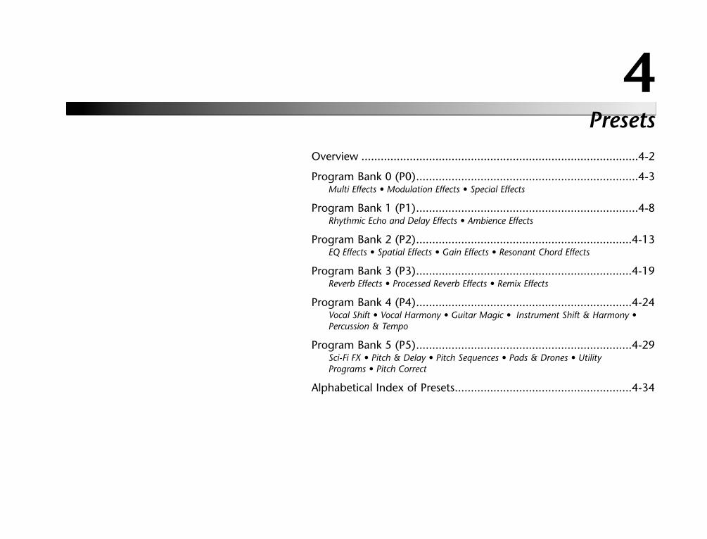
Presets
4Overview ......................................................................................4-2
Program Bank 0 (P0).....................................................................4-3Multi Effects • Modulation Effects • Special Effects
Program Bank 1 (P1).....................................................................4-8Rhythmic Echo and Delay Effects • Ambience Effects
Program Bank 2 (P2)...................................................................4-13EQ Effects • Spatial Effects • Gain Effects • Resonant Chord Effects
Program Bank 3 (P3)...................................................................4-19Reverb Effects • Processed Reverb Effects • Remix Effects
Program Bank 4 (P4)...................................................................4-24Vocal Shift • Vocal Harmony • Guitar Magic • Instrument Shift & Harmony •Percussion & Tempo
Program Bank 5 (P5)...................................................................4-29Sci-Fi FX • Pitch & Delay • Pitch Sequences • Pads & Drones • UtilityPrograms • Pitch Correct
Alphabetical Index of Presets.......................................................4-34
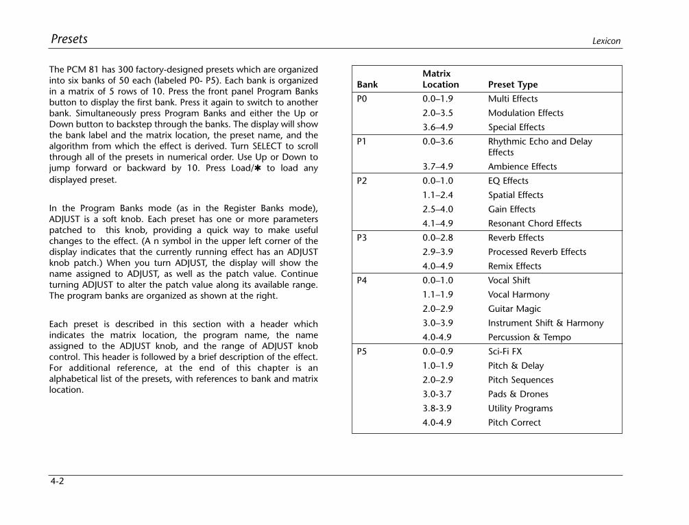
MatrixBank Location Preset Type
P0 0.0–1.9 Multi Effects
2.0–3.5 Modulation Effects
3.6–4.9 Special Effects
P1 0.0–3.6 Rhythmic Echo and DelayEffects
3.7–4.9 Ambience Effects
P2 0.0–1.0 EQ Effects
1.1–2.4 Spatial Effects
2.5–4.0 Gain Effects
4.1–4.9 Resonant Chord Effects
P3 0.0–2.8 Reverb Effects
2.9–3.9 Processed Reverb Effects
4.0–4.9 Remix Effects
P4 0.0–1.0 Vocal Shift
1.1–1.9 Vocal Harmony
2.0–2.9 Guitar Magic
3.0–3.9 Instrument Shift & Harmony
4.0-4.9 Percussion & Tempo
P5 0.0–0.9 Sci-Fi FX
1.0–1.9 Pitch & Delay
2.0–2.9 Pitch Sequences
3.0-3.7 Pads & Drones
3.8-3.9 Utility Programs
4.0-4.9 Pitch Correct
4-2
Presets Lexicon
The PCM 81 has 300 factory-designed presets which are organizedinto six banks of 50 each (labeled P0- P5). Each bank is organizedin a matrix of 5 rows of 10. Press the front panel Program Banksbutton to display the first bank. Press it again to switch to anotherbank. Simultaneously press Program Banks and either the Up orDown button to backstep through the banks. The display will showthe bank label and the matrix location, the preset name, and thealgorithm from which the effect is derived. Turn SELECT to scrollthrough all of the presets in numerical order. Use Up or Down tojump forward or backward by 10. Press Load/ to load anydisplayed preset.
In the Program Banks mode (as in the Register Banks mode),ADJUST is a soft knob. Each preset has one or more parameterspatched to this knob, providing a quick way to make usefulchanges to the effect. (A n symbol in the upper left corner of thedisplay indicates that the currently running effect has an ADJUSTknob patch.) When you turn ADJUST, the display will show thename assigned to ADJUST, as well as the patch value. Continueturning ADJUST to alter the patch value along its available range.The program banks are organized as shown at the right.
Each preset is described in this section with a header whichindicates the matrix location, the program name, the nameassigned to the ADJUST knob, and the range of ADJUST knobcontrol. This header is followed by a brief description of the effect.For additional reference, at the end of this chapter is analphabetical list of the presets, with references to bank and matrixlocation.
4-3
PresetsPCM 81
PROGRAM BANK 0 (P0)
MULTI EFFECTS
0.0 Prime Blue ADJUST: Efx/Rvb X 0–127
A combination of 3 stereo effects: 6 voice chorus, rhythmic echoes,and reverb. You can dial-in the exact proportion of each. AsADJUST is turned from 0 to 127 the effect smoothly changes fromchorus only , to chorus with echoes, to chorus with echoes andreverb, to reverb with echoes, and finally to reverb only. Use Tap toset the echo rhythms.
0.1 EkoChorus ADJUST: FX Mix 0–127
A 6 voice stereo chorus with echoes and stereo reverb. ADJUSTcontrols the mix of chorus/echoes with reverb. The Soft Rowprovides all the tweaks you’ll need to get the most out of thisclassic multi effect.
0.2 Wet Chorus ADJUST: FX Mix 0–100
This is a thick wet chorus combined with a small amount of reverbto produce a large lush sound. It can fatten up any track and isespecially good for adding body to guitar. ADJUST controls thecombination of delays and chorus with reverb.
0.3 Wet Chorus 2 ADJUST: FX Mix 0–100
This is a variation of Wet Chorus with a subtle amount of delays andreverb to produce just the right amount of ambience. ADJUSTcontrols the combination of delays and chorus with reverb.
0.4 Wet Chorus 3 ADJUST: FX Mix 0–100
A variation of Wet Chorus 2 with even thicker chorus (bordering ona slight flange) and slightly modified delays. ADJUST controls thecombination of delays and chorus with reverb.
0.5 Chorus Plate ADJUST: KorusMix 0–100
Combination of smooth rolling delays in the reverb shell combinedwith a more aggressively modulated reverb tail. ADJUST changesthe non-modulated to modulated reverb tail. Twisted for guitar.
0.6 Chorus Room ADJUST: Decay 0–80
Slow chorus applied to one side of the reverb. The speed of themodulation follows input level. ADJUST controls the reverb decay.
0.7 ChorusToRvb ADJUST: Decay 0–127
Input level controls the relative mix of stereo chorus and reverb.Loud signals are mostly chorus and the reverb level comes up asthe signal fades away. ADJUST controls the reverb decay time.
0.8 Funkus Room ADJUST: LFO Rate 0–100
This preset works great on electronic pianos / keyboards. Strongmodulation applied to both delays and reverb tail. ADJUST con-trols the speed of the LFO modulation.
0.9 Detune & Room ADJUST: Detune 0–127
A very tight room combined with separate pitch modulation on theleft and right inputs. ADJUST controls the depth of the detuning.
4-4
Presets Lexicon
PROGRAM BANK 0 (P0) (continued)
MULTI EFFECTS (continued)
1.0 Detune&Dbl ADJUST: Detune 0–127
Similar to Detune & Room, but several delay voices have beenadded to produce doubling effects. ADJUST controls the amount ofdetune on each side. Soft Row goodies include a master delaycontrol that allows you to vary the time difference between thedelay voices.
1.1 Tight Space ADJUST: SplitWide 0–100
A bright, dry ambience combined with left and right detune anddelay. ADJUST controls the amount of detune as well as the left/right delay spread.
1.2 Flange >Rvb ADJUST: FX Mix 0–100
This stereo effect feeds the output of a flanger into a concert hallreverb. ADJUST controls the mix of dry and wet flanged audio. TheSoft Row includes master delay and feedback parameters foradding echoes, as well as parameters for modulation and imagecontrol.
1.3 Flange+Rvb ADJUST: FX Mix 0–100
A rich 6 voice chorus in parallel with reverb. ADJUST controls themix of the two independent stereo effects. The Soft Row includesthe essential parameters for creating many variations of this classiccombination of effects.
1.4 X Eko Flange ADJUST: X-Fbk 0–100
A stereo flanger with rhythmic echoes feeding into stereo reverb.ADJUST controls the cross-feedback of the echoes (which causesthem to bounce from side to side as they repeat). Press Tap tosynchronize the echoes with rhythmic sources.
1.5 Glide > Verb ADJUST: FX Mix 0–100
Three stereo effects in series: gliding delays, rhythmic echoes andreverb. ADJUST controls the mix of delay effects and reverb.Essential controls for each effect are included in the Soft Row.
1.6 Glide X-Ekos ADJUST: Eko Time 0–100
Similar to Glide > Verb, but ADJUST lets you dial in echo times from0 to 2 seconds. Feedback and cross feedback are combined tocreate echo patterns that change as they repeat.
1.7 Detuned Ekos ADJUST: Ekos/Beat 1–24
Plate reverb combined with independent stereo delays. The delayvoices are diffused and modulated. The echoes are rhythmic — setthe tempo with Tap or MIDI clocks. Use ADJUST to set the numberof echoes per beat.
1.8 StereoEqEkos ADJUST: Ekos/Beat 1–24
Six rhythmic echo voices are EQ’d and panned across stereo space.ADJUST sets the number of repeats per beat.
1.9 ADJUpMyEchos ADJUST: EchosLvl 0–10
Concert Hall reverb with 4 panned echo voices in the background.ADJUST controls the level of the echo voices. Press Tap tosynchronize the echoes with rhythmic material.
4-5
PresetsPCM 81
MODULATION EFFECTS
2.0 FSw2 Elevate ADJUST: Feedback 0–99
Similar to Detuned Ekos, multiple echo voices with diffusion, mod-ulation and a touch of plate reverb. In this effect, Foot Switch 2 ispatched to turn on the AR Envelope which, in turn, sweeps themaster delay. ADJUST controls the feedback of these rhythmicechoes.
2.1 Chorus &Pan ADJUST: LFO Rate 0–100
This moving chorus shifts the output signal from left to right, backand forth. ADJUST sets the speed. Increasing the Delay Masterparameter will smear the delay images.
2.2 Chorus&Amb ADJUST: MstChorus 0–100
Similar to Chorus&Pan but with an added ambience. ADJUST con-trols the speed and depth of the chorus.
2.3 6 Vox Chorus ADJUST: Less/More 0–50
Starting point for all chorus sounds. ADJUST controls both the cho-rus depth and speed. Use the Delay Master to open or close thespacing between the 6 delay voices.
2.4 Split C&E ADJUST: InputPan 0–100
The left input is processed into a lush 3-voice chorus with the voicepanners adjusted from center to left. The right input is processedinto a rhythmic 3-voice echo with the output panned from centerto right. ADJUST cross-pans the inputs. 0 = left/right stereo,50 = mono, 100 = right/left stereo.
2.5 Env:PanKorus ADJUST: Chorus 0–127
The AR Envelope drives the speed of the pan based on the presenceor absence of input signal. ADJUST varies the chorus amount.
2.6 6 Vox Flange ADJUST: MstrDepth 0–100
A rich stereo flanger with a touch of reverb. ADJUST controls theflange depth.
2.7 Mod Max ADJUST: Mod Knob 0–50
Multiple parameters all being modulated together. With a stereoinput the LFO drives the input pans to each delay and reverbprocessor. A definite "twist your head off" effect. ADJUST controlsseveral aspects of the modulation.
2.8 PreciseGlide ADJUST: Resonance 0–100
A very clean stereo gliding delay and reverb. ADJUST controls theresonance of the glide. Soft Row includes master delay and feed-back parameters so you can add stereo echoes to the effect.
2.9 Round 147 ADJUST: RotorRate 0–20
Big wooden rotary speaker cabinet miked fairly close. ADJUST setsthe speed of the rotors. FX Mix is available in the soft row to con-trol the amount of reverb relative to the total effect output.
3.0 FSw2 Rotary ADJUST: Width 0–100
A dual-rotor speaker cabinet with a very wide stereo spin and atouch of ambience. Use ADJUST to control the width and directionof the spinning rotors. 0= very wide left-to-right, 64 = mono, 127= very wide right-to-left. Foot Switch 2 is patched to the Latch totoggle between slow and fast speeds. The AR envelope is used tosimulate the inertial drag as the rotors speed up or slow down.
4-6
Presets Lexicon
PROGRAM BANK 0 (P0) (continued)
MODULATION EFFECTS (continued)
3.1 RotorCabinet ADJUST: Slow/Fast 0–1
Similar to FSw2 Rotor, but ADJUST is used to toggle the speed ofthe rotors between slow and fast. Soft Row parameters include FXWidth which sets the width and direction of the spin.
3.2 MIDI Rotary ADJUST: EkoFbk 0–100
Similar to FSw2 Rotor, but with echoes added and the rotorspatched up for MIDI control. MIDI After Touch toggles speed.Press hard to spin fast, press hard again to spin slow. ADJUSTcontrols the amount of echo feedback. Use Tap to synchronize theechoes with rhythmic material.
3.3 Tiled Rotary ADJUST: Slow/Fast 0–1
The RotorCabinet effect in a tiled room. Try it with backgroundvocals, as well as the usual keyboard and guitar sources. ADJUSTtoggles the spin rates between slow and fast.
3.4 RotoWood ADJUST: Speed 0–10
ADJUST quickly advances the speed of the rotors. Increase theFeedback Master for more upper rotor “howling”.
3.5 RandomImages ADJUST: ImageKnob 0–127
This effect works best with solo instruments or voices. Individualinput notes come out at random locations in the stereo image.ADJUST varies delay time, adds chorusing, and turns up temporelated echo levels. Delays "creep" slowly out to new time values.
SPECIAL EFFECTS
3.6 Under Water ADJUST: DrownKnob 0–100
This effect really pulls you under! It will submerge any track underwater. ADJUST controls the over all rate of the effect.
3.7 Thunder FX ADJUST: FlashTime 0–127
An unusual special effect that produces a rolling clap of thunderfrom a percussive source (tom toms , etc.) and ethereal sweepsfrom synth pads. The effect is driven by the AR Env, which isavailable in the soft row. ADJUST controls the AR release rate.
3.8 Thunder FX 2 ADJUST: FlashTime 0–127
A variation of Thunder FX. The zaps are produced by setting amuch faster release rate. ADJUST controls the release rate.
3.9 ChaosImpuls ADJUST: GldResp 0–100
This special effect is hard to describe but interesting to listen to. Itproduces chaotic rhythms and detunings from the input source.ADJUST sets the chaotic limits. Try this with individual percussivehits.
4.0 DemonDescent ADJUST: GldResp 0–100
Dark reverb and modulated detuning are combined to create aneerie special effect. ADJUST controls the rate and depth of thedetuning.
4.1 RoughIdle FX ADJUST: Speed 0–127
Use this to mutate any steady, broad band source into a poorlytuned combustion engine. ADJUST controls the speed.
4-7
PresetsPCM 81
4.2 RoxStutter ADJUST: FX Mix 0–100
Use on those strong rock and roll lead vocals. The trailing echoeson voices 3 and 4 go longer as the signal disappears. ADJUSTcombines the delay effects with a plate reverb effect. Delays 2 and5 are available in the soft row to add more echo presence.
4.3 Split Pitch? ADJUST: SplitWide 0–127
Modulated varispeed in stereo. One side goes low as the other sidegoes high. ADJUST controls the rate and depth of the varispeed.Good for special FX processing of various sources including synthsand dialog.
4.4 TryTalk’n ADJUST: GldResp 0–100
A variation of Split Pitch? In this version highly colored reverb andadditional delay voices have been added. ADJUST controls the rateand depth of the varispeed.
4.5 AutoInfinite ADJUST: FX Mix 0–100
With signal present the reverb time runs long. With signal absentthe infinite process is switched on. The threshold for the event isset high such that after a source is running in the infinite process,you can play softer passages against it which chorus and echo atthe same time. AR Envelope parameters are included in the softrow. Adjust the threshold to suit your application.
4.6 Remove Cntr ADJUST: Cntr Fc 0–127
This effect uses filters and crosstalk cancellation to remove monomaterial from a stereo mix. ADJUST controls a low pass filter for thecenter channel frequencies. As it is turned from 0-127 monomaterial is added back into the mix.
4.7 V-Eliminate ADJUST: Cut Zone 0–127
This effect is a vocal eliminater. It is similar to Remove Cntr, in thatit will remove mono material from a stereo mix. In this effect,however, only frequencies in the vocal range are removed. Thiskeeps mono low and high frequencies (kick, bass, snare cymbals,etc.) in the mix. ADJUST controls the width of the eliminationband. Note that phase cancellation will occur if the two outputs aresummed to mono.
4.8 NoCenter Eko ADJUST: Center Fc 0–127
This is the same effect as Remove Center with delays added to theprocessed signal. It allows you to add echoes to the left and rightmaterial without affecting the mono material of a stereo mix or submix. For example, you can add additional echoes to a mix withoutaffecting the vocals, kick or snare. ADJUST controls a low pass filterfor the center channel frequencies.
4.9 Rvb On L–R ADJUST: Decay 0–127
Similar to NoCenterEko, this effect adds dense plate reverb to theleft and right material without affecting the mono material in astereo mix. ADJUST controls the mid Rt of the reverberator.

4-8
Presets Lexicon
PROGRAM BANK 1 (P1)
RHYTHMIC ECHO AND DELAY EFFECTS
Note:The echoes in all of the Rhythmic Echo and Delayeffects can be synchronized to tempo. Tempo is set bydialing it in, pressing Tap, or selecting MIDI Clock asthe Tempo. (Tempo mode 0.2) Be sure to try theseeffects synchronized with MIDI sequence and drumpatterns.
0.0 [n]Ekos/Beat ADJUST: [n] 1–24
This preset produces stereo echoes with a touch of reverb. ADJUSTcontrols the number of echoes per beat. Soft Row goodies includecontrols for master scaling of the delay rhythms and feedback, EQand panning, as well as reverb parameters.
0.1 StereoTapDly ADJUST: Mstr Fbk 0–100
A variation of [n]Ekos/Beat this effect has left and right delayvoices. ADJUST controls master feedback for both voices. The SoftRow includes controls for rhythm, feedback and panning for eachvoice
0.2 OffBeat Eko ADJUST: DarkKnob 0–127
This variation of [n]Ekos/Beat produces a syncopated echo rhythmpattern. ADJUST controls high cut filters in the echo feedback paths– great for “tape”echo effects.
0.3 OffBeat Eko2 ADJUST: DarkKnob 0–127
Additional rhythmic delay voices are used to create a morecomplicated syncopation pattern than OffBeat Eko. ADJUSTcontrols high cut filters in the echo feedback paths – great for“tape” echo effects.
0.4 Dotted 8ths ADJUST: EchoSlope 0–127
Rhythmic delay voices produce a dotted 8th-note pattern. ADJUSTcontrols the slope of the first six repeats. 0 = loud to soft (normalechoes), 64 = six repeats of equal loudness, 127 = soft to loud(reversed echoes).
0.5 Shuffle Ekos ADJUST: Shufl Lvl 0–127
This effect creates echoes with a shuffle feel. One repeat on thebeat followed by one repeat off the beat. ADJUST controls therelative levels of the on-beat and off-beat echoes. 0 = on-beat echoonly, 127 = off-beat echo only.
0.6 Shuffles ADJUST: EchoSlope 0–127
Rhythmic delay voices produce a shuffle pattern. ADJUST controlsthe slope of the first six repeats. 0 = loud to soft (normal echoes),64 = six repeats of equal loudness, 127 = soft to loud (reversedechoes).
0.7 Sliding Eko ADJUST: Slide It! 0–100
This stereo delay effect lets you dial in the perfect “feel” to matchthe moment. Two echoes are produced. One is fixed on the beat.The other can be slid in musical time anywhere in front of orbehind the beat by turning ADJUST. 0-49 = in front of the beat, 50= on the beat, 51–100 = behind the beat. Of course, the Soft Rowcontains additional controls for fine tuning the effect.
4-9
PresetsPCM 81
0.8 Six Trips ADJUST: EchoSlope 0–127
Rhythmic delay voices produce a six note triplet pattern. Eachrepeat gets progressively louder. ADJUST controls the slope of thefirst six repeats. 0 = loud to soft (normal echoes), 64 = six repeatsof equal loudness, 127 = soft to loud (reversed echoes).
0.9 6 StrokeRoll ADJUST: Attack 0–127
Turn a single drum hit into a six-stroke roll with this effect. ADJUSTcontrols the attack of the first five repeats. 0 = loud to soft (normalechoes), 64 = five repeats of equal loudness, 127 = soft to loud(reversed echoes).
1.0 TapGated Rvb ADJUST: Gate dB 0–85
This effect uses a tempo-controlled LFO as a rhythmic gate to theinputs of a large stereo chamber. The gate is opened every otherbeat for a duration of one eighth-note. Use this to add reverb toselected beats of a stereo source. (Try this one synchronized toMIDI with a drum machine as a source.) ADJUST controls the inputlevels in dB to the reverb when the gate is closed. 0 = always open(0dB), 85 = fully closed (-85dB). The Soft Row includes the LFOparameters so you can adjust the overall timing of the gate.
1.1 TapEkoGate 1 ADJUST: GateWidth 0–127
This effect uses a tempo-controlled LFO as a rhythmic gate to theinputs of a delay and reverb combination. The gate is opened onceevery four beats for a duration of one eighth-note. ADJUSTdetermines the portion of the four beats in which the gate is open.0 = open for all four beats, 127 = open for only the first 16th noteof four beats. The Soft Row includes the LFO parameters so you canadjust the overall timing of the gate.
1.2 TapEkoGate 2 ADJUST: GateWidth 0–127
This is a variation of TapEkoGate 1 with different echo rhythms.ADJUST determines the portion of the four beats in which the gateis open. 0 = open four all four beats, 127 = open for only the first16th note of four beats. The Soft Row includes the LFO parametersso you can adjust the overall timing of the gate.
1.3 TapEkoClear ADJUST: GateWidth 0–127
This preset is similar to the two TapEkoGate presets, except that therhythmic gate is also patched to clear the delay voices when itopens. This allows very high delay feedback values to be usedwithout creating long echo trails. ADJUST determines the portionof the four beats in which the gate is open. 0 = open for all fourbeats, 127 = open for only the first 16th note of four beats. TheSoft Row includes the LFO parameters so you can adjust theoverall timing of the gate.
1.4 Tap Chamber1 ADJUST: Width 0–90
This preset is a tempo controlled variation of SnareChamber. Theeffect is a tight chamber with liveness that is constantly changing.The change is tempo controlled. Press Tap to synchronize it to thebeat. ADJUST controls the width of the reverb within the overallstereo image of the effect (0 = mono, 45 = stereo, 90 = surround).Use this to open up sampled drum mixes.
1.5 Tap Chamber2 ADJUST: Decay 0–127
This is a version of Vox Chamber with a rhythmic twist. The widthof the reverb, within the overall stereo image of the effect, ischanged rhythmically by Sw 1. This change is tempo controlled.Press Tap twice to synchronize to the beat. ADJUST controls reverbdecay.
4-10
Presets Lexicon
PROGRAM BANK 1 (P1) (continued)
RHYTHMIC ECHO AND DELAY EFFECTS (continued)
1.6 LatchedEkos ADJUST: EchoWidth 1–99
The inputs and outputs of stereo delays are gated on and off bytwo rhythmic switches. The Latch is used to trigger the ARenvelope, which in turn alternates the left and right delay outputs.ADJUST controls how long the inputs to the delays remain openover a period of four beats.
1.7 X-PanEQ BPM ADJUST: Low Tone 0-60
This effect cross-pans the inputs between independent left andright band pass filters and adds some bright, highly diffused reverb.The pan rate is tempo controlled. ADJUST controls the lowfrequency limits of both bands.
1.8 Pan->Eko BPM ADJUST: DarkKnob 0–127
This effect pans the inputs across the stereo inputs of a reverb andindependent left and right delays, each with slightly different EQ.The pan rate is tempo controlled. ADJUST controls the highfrequency limits of both bands.
1.9 Tempo Verb ADJUST: Liveness 0–40
In this tempo-based reverb effect, decay changes in tempo. Slowtempos yield longer reverb time; fast tempos result in shorterdecay. Set tempo with two presses of Tap, or with MIDI.
2.0 Tempo Gate ADJUST: High Cut 0-50
This heavily gated reverb effect has duration set by tempo. Tap intwo quarter-notes to set the gate duration.
2.1 Tape Echo ADJUST: DarkKnob 0–127
This preset simulates a stereo tape echo. The echo rate is tempocontrolled. Press Tap to synchronize with rhythmic material.ADJUST controls high frequency damping – the echoes get darkeras they repeat. The Soft Row includes parameters for adding andreverb as well additional controls for the delays and filters.
2.2 NonLinear 1 ADJUST: EchoSlope 0–127
This effect produces echoes with non linear decay. ADJUST controlsthe decay slope. 0 = loud to soft (normal echoes), 64 = sixrepeats of equal loudness, 127 = soft to loud (reversed echoes). Inthis preset the slope is set to produce a simple reversed echo effect.The repeat rate is tempo controlled. The Soft Row containsparameters for controlling the stereo image, adding reverb, scalingthe repeat rate, and more.
2.3 NonLinear 2 ADJUST: EchoSlope 0–127
Similar to NonLinear 1, with some additional processing. Chorusand reverb have been added, and the delays bounce from side toside as they repeat. In this preset the slope is set to 64 to producerepeats of equal loudness. The Soft Row includes parameters forcontrolling the stereo image, chorus depth and rate, etc.
2.4 NonLinear 3 ADJUST: EchoSlope 0–127
This is a variation of NonLinear 2 with more radical processing andan inverted slope.
2.5 Six Across ADJUST: Spacing 0-100
This multi-tap delay effect filters each voice to a specific bandbasswith each tap positioned successively across the panoramicspectrum. ADJUST controls the overall spacing between the voices.
4-11
PresetsPCM 81
2.6 BandEko Rvb ADJUST: Center Fc 0–127
In this preset, the outputs of a stereo band pass filter are sent to leftand right rhythmic delays. These delays are in the reverb diffusorloop. The effect produces diffuse, highly colored echoes and reverb.Use ADJUST to set the center frequency of the band pass filter.
2.7 BandEkoSweep ADJUST: Mstr Fbk 0–100
A variation of BankEko Rvb. The center frequency of the band passfilter is swept by the LFO producing echoes of shifting colors.Reverb and diffusion are turned off, but can be added from the SoftRow. ADJUST controls master feedback for the left and right delays.
2.8 LFO EQ Echo ADJUST: LC Depth 0–100
A stereo rhythmic effect created by modulating low cut and highcut filters with the LFO sine and cosine waves. Interesting onrhythm tracks and individual instruments. ADJUST controls thedepth of the low cut modulation.
2.9 Chase Echo ADJUST: ChaseRate 0–100
This is LFO EQ Echo with panning added to the filtered delayoutputs. ADJUST controls the pan rate.
3.0 Panned Dlys ADJUST: Mstr Fbk 0–100
In this effect, a pair of delays are panned to produce echoes thatdrift across stereo space. ADJUST controls the feedback of bothdelays. More goodies await you in the Soft Row.
3.1 X-Pan Delays ADJUST: Mstr Fbk 0–100
The outputs of the delay pair are cross-panned in this effect. Monomaterial will produce echoes that repeat, but remain in the center.Stereo material will slowly swap left and right as it repeats. UseADJUST to set the feedback for both delays.
3.2 Dly>EQ>Pans ADJUST: Mstr Fbk 0–100
The input signal is split into two frequency bands by this effect. Thetwo bands are then sent through two different rhythmic delayswhose outputs are panned in opposite directions. This effectdeconstructs the tone of input material, except when the panningand delay rhythms align in the center of the stereo field. Try it witha drum mix or other broad band material. Use ADJUST to set thefeedback for both delay voices.
3.3 Ekoz 4 Drums ADJUST: FX Mix 0–100
This preset is a space setter for percussive instruments. It combinesa short plate reverb effect with four high density echoes which arehighly diffused. ADJUST varies the amount of delay effect to reverbeffect.
3.4 Haas PanKnob ADJUST: L=0, R=127 0–127
A panner that uses the slight differences in left and right channeldelay to produce panning without changing relative levels. UseADJUST to pan from left to right.
3.5 Dial a Delay ADJUST: Delay 0–100
This one is your basic delay. Use ADJUST to dial-in up to 2.5 sec-onds of stereo delay. The Soft Row will take you beyond the basics,with parameters for reverb design, EQ and feedback.
3.6 PrecisionDly ADJUST: L ms/100 0–100
Use this preset if you need precise alignment of left and rightchannel audio. ADJUST allows you to offset the left channel by upto 1 ms in 100 increments. The Soft Row contains two sets ofadditional delay controls for the left and right channels, each with1ms resolution, as well as independent level and panning controls.
4-12
Presets Lexicon
PROGRAM BANK 1 (P1) (continued)
AMBIENCE EFFECTS
3.7 PhoneOrRoom? ADJUST: Pick One 0–1
Use ADJUST to choose between a mono telephone filter and a smallroom with stereo ambience. The Soft Row provides access to thefilter controls as well as reverb design parameters.
3.8 CheapTV Room ADJUST: The Walls 1–10
This stereo preset simulates the sound of a Lo-Fi TV in a small room.Use ADJUST to change the reflectivity of the walls. The Soft Rowprovides access to filter controls and reverb design parameters.
3.9 Empty Stage ADJUST: Liveness 0–100
Made for creating live sounding spaces. ADJUST opens the space tobe more reflective and airy.
4.0 Tomb Room ADJUST: The Walls 1–10
Use this ambience preset to place source material within a veryreflective tomb. ADJUST moves the source deeper into this scaryspace.
4.1 Comb Room ADJUST: Tone 0–100
This effect provides a tunable comb filter and reverb to produce ahighly colored ambience. Use ADJUST to change the tuning of thecomb filter.
4.2 Zoom Over ADJUST: Speed 1–25
Run an effect (or even a continuous synthesizer drone) into thispreset, and the sound will approach you from the center, spreadout to the sides as it passes overhead, and recede into the distancebehind you. ADJUST controls the speed of the fly-by. This effect willimage properly in either 2-channel or Surround mixes.
4.3 OneShotCarBy ADJUST: Speed 1–100
Input level triggers this left-to-right drive-by. When signal isdetected, it will move from left to right. Doppler pitch shift issimulated as the image moves across the stereo field. Use ADJUSTto set the speed of the drive-by. Once audio has been detected, theeffect will cycle once. To drive by again, stop and restart the audiotrack. To reverse the direction of the effect, set the Widthparameter to –45 — you’ll find it in the Soft Row.
4.4 AmbientCarBy ADJUST: Speed 1–100
This is a variation of OneShotCarBy. In this preset the effect isenhanced with the addition of some stereo ambience. Also, in thisvariation the effect repeats automatically. ADJUST controls thespeed of the drive-by.
4.5 HeadOn CarBy ADJUST: Speed 1–100
This preset uses less ambience than ZoomOver, and is moreappropriate for things that approach on the road than in the air.ADJUST sets the speed of the effect. This effect will image properlyin either 2-channel or Surround mixes.
4-13
PresetsPCM 81
4.6 2WayStreet ADJUST: Speed 1–100
Another variation of AmbientCarBy. This preset produces bothleft-to-right and right-to-left drive-by effects — like listening to thesound of traffic on a two-way street. The speed for each directionis slightly different. ADJUST is a master speed control for botheastbound and westbound traffic.
4.7 IntoTunnel ADJUST: Speed 1–25
This preset simulates the sound of a source approaching you fromthe side, passing you and then entering a tunnel. ADJUST controlsthe speed of the source. To reverse the direction of the effect, setthe Width parameter to –45 — you’ll find it in the Soft Row.
4.8 2WayTunnel ADJUST: Speed 1–100
This is a variation of IntoTunnel. The source approaches and entersthe tunnel, then turns around and comes back. Use ADJUST to con-trol the speed.
4.9 FinishLine ADJUST: Speed 1–100
This preset adds two pairs of stereo delays to the basic drive-byeffect to simulate the 1st, 2nd, and 3rd place cars crossing the fin-ish line. ADJUST controls the speed. Be sure to try this and theother drive-by effects with different types of source material.Almost any continuous source will produce interesting spatialsound effects. Low, buzzy synthesizer tones work particularly well.
PROGRAM BANK 2 (P2)
EQ EFFECTS
0.0 StereoLoPass ADJUST: CutOff 0–127
This effect is a combination of a stereo low pass filter and a stereoreverb, with the two effects in parallel. Use ADJUST to set the cutoff frequency of the filter. The reverb mix is turned all the waydown — you can add reverb by changing the FX Mix parameter inthe Soft Row, where you’ll also find additional parameters for delayvoices, and image.
0.1 Low Pass HiQ ADJUST: Cutoff 0–127
The same basic effect as StereoLoPass, but with feedback adjustedto produce a more resonant filter. ADJUST sets the cutofffrequency of the filter.
0.2 Low Pass LFO ADJUST: Depth 0–127
The cutoff of the stereo low pass filter is swept with a rhythmic LFOsine wave. Press Tap to synchronize the sweep with rhythmicmaterial. ADJUST controls the low frequency limit of the sweep.
0.3 StereoHiPass ADJUST: Cutoff 0–127
A combination of a stereo high pass filter and a stereo reverb, withthe two effects in parallel. Use ADJUST to set the cutoff frequencyof the filter. The reverb mix is turned all the way down — you canadd reverb by changing the FX Mix parameter in the Soft Row,where you’ll also find additional parameters for delay voices, andimage.
4-14
Presets Lexicon
PROGRAM BANK 2 (P2) (continued)
EQ EFFECTS (continued)
0.4 StereoB-Pass ADJUST: Center 0–127
A combination of a stereo band pass filter and a stereo reverb, withthe two effects in parallel. Use ADJUST to set the center frequencyof the filter. The reverb mix is turned all the way down — you canadd reverb by changing the FX Mix parameter in the Soft Row,where you’ll also find additional parameters for delay voices, andimage.
0.5 Stereo Notch ADJUST: Center 0–127
A variation of StereoB-Pass which combines a phase invertedoutput of the band pass filter with unprocessed signal to create anotch filter. ADJUST sets the center frequency of the notch.
0.6 SweptNotches ADJUST: Rate 0–100
This preset produces vowel-like sounds by sweeping two pairs ofnotches with two independent time switches. This effect willproduce very unusual tonal variations from broad band sources(rich pads, drums, industrial sound effects, etc.) It also generates agood deal of spatial movement within a stereo or Surround mix.ADJUST controls the rate of the sweeps.
0.7 Env Notches ADJUST: Release 0–100
This preset will produce vocalization effects from dynamic sources.The inputs are summed to mono, and the notch filters which aretuned to vocal formats are swept by the resulting input envelope.ADJUST controls the release rate of the input envelope.
0.8 BandReject 4 ADJUST: FX Mix 0–100
Three independent modulators are used to sweep filters and panthe outputs of this preset. The result is an effect with constantlychanging tonal and spatial characteristics. A touch of reverb addssome overall ambience. Use ADJUST to set the mix of filters andreverb.
0.9 WaaPedalEko ADJUST: FeedBack 0–10
Wah-wah with echoes. Foot pedal is patched to filter cutoff.ADJUST controls echo feedback.
1.0 RotorWaa ADJUST: Rate 0–10
A tempo controlled wah-wah effect. ADJUST controls the rhythm ofthe modulator.
SPATIAL EFFECTS
1.1 Movable Echo ADJUST: Position 0-127
This preset is designed for use with either stereo or Surround mixes.It is a dual delay effect that can be positioned anywhere betweenthe center, side and rear channels. ADJUST sets the position.0 = center, 64 = side channels, 127 = rear channel.
1.2 Movable Hall ADJUST: Position 0–127
Like Movable Echo, this preset is designed for use with either stereoor Surround mixes. It is a concert hall reverb effect that can bepositioned anywhere between the center, side and rear channels.ADJUST sets the position. 0 = center, 64 = side channels, 127 = rearchannel.
4-15
PresetsPCM 81
1.3 Go Away ADJUST: How Far? 0–127
Use this preset to take a stereo source and move it anywhere fromin your face to far, far away. Use ADJUST to move the source awayfrom you. 0 = unprocessed stereo, 127 = far away. As ADJUST isincreased, EQ, reverb and stereo width are all changed to producethe composite effect. This effect is compatible with stereo andSurround mixes.
1.4 Circular Pan ADJUST: Rate 0–100
Similar to Go Away, this preset sums the inputs to mono and usesthe LFO to control EQ, reverb and stereo width to pan the soundthrough a circular orbit. From right through center,to left throughrear, to right. As the sound approaches the center, it growsbrighter, louder and dryer. As it recedes towards the rear, it growsdarker, softer and more reverberant. In a Surround mix, the centerand rear positions of the orbit will feed only the center and rearchannels of the mix. ADJUST controls the rate of the pan.
1.5 Spatial Hall ADJUST: Position 0–35
A multi-dimensional preset which changes as you increase ordecrease the ADJUST knob value. This preset is not monocompatible.
1.6 Rear of Hall ADJUST: Decay 0–60
This is a really huge space and you’re in the back of it. ADJUSTchanges the reverberation characteristics, making it boomier.
1.7 Backstage ADJUST: How Far? 0–127
Remember what the concert sounded like from the green room? Ifyou need to re-create that ambience, this preset will take you thereand let you wander around. Turn up ADJUST to travel further fromthe stage until, finally, you’re out in the parking lot. The Soft Rowprovides reverb parameters that will let you fine tune the the hallto fit your needs.
1.8 Steered Rear ADJUST: Decay 0–10
The Width parameter steers this plate effect from front to back afterthe AR releases based on input level. ADJUST controls reverb decay.Due to the strong spatial positioning at the end of the decay, thispreset is not mono compatible.
1.9 Too Deep! ADJUST: Decay 0–40
The left and right envelope followers control the post delay glideswhile the AR generator controls reverb width. ADJUST controlsreverb decay.
2.0 Dyna-Hall ADJUST: Decay 0–130
A tamer version of Too Deep! No envelope chorusing. Good,beautiful, straight ahead, and spacious.
2.1 RotoRox ADJUST: FX Mix 0-100
RotoRox crossfades deeper into two delay voices when theenvelope follower detects an absence of input. Great vocal effectsfor thickly-produced rock and roll. ADJUST will add more or lessreverb into the effects mix.

4-16
Presets Lexicon
PROGRAM BANK 2 (P2) (continued)
SPATIAL EFFECTS (continued)
2.2 RotoRoomVox ADJUST: Decay 0–100
This medium large sized room continuously changes spatial widthaccording to the speed of the LFO which tracks the input. Fasterwith less input, slower with more input. ADJUST controls reverbdecay. Nice roomy effect for background vocals.
2.3 RotoRoom ADJUST: Decay 0–60
Similar to RotoRoomVox except the speed of the spatial widthmodulation is stable, with the speed of the LFO constant. Room issmaller, more dense-sounding and brighter.
2.4 RotoRoom#2 ADJUST: Rt & Rate 0–60
Speed and reverb decay are tied to ADJUST. Way cool on a stingersound effect! Dynamically spacious and not mono compatible.
GAIN EFFECTS
2.5 Tremolo Tap1 ADJUST: Depth 0–127
This is a basic tremolo effect with a small amount of ambienceadded. The effect is true stereo. The left and right channels areprocessed separately to maintain the image of stereo sourcematerial. The tremolo rate is tempo controlled (2 cycles/beat).Press Tap to synchronize the effect with rhythmic material. ADJUSTsets the tremolo depth. 0 = no tremolo, 127 = maximum tremolo.
2.6 X-TremoloTap ADJUST: Depth 0-127
This a variation of TremoloTap1. In this preset the left and rightmodulation are 90° out of phase, producing a stereo effect thatdoesn’t collapse in a mono mix. If the input source is mono, thesound will seem to move from side to side. If the input source isstereo (or two different mono sources) the left and right channelswill alternately grow loud and soft. The modulation rate is tempocontrolled. ADJUST controls the tremolo depth for both channels.0 = no tremolo, 127 = maximum tremolo.
2.7 Panner BPM ADJUST: Pan Phase 0–1
This effect is a tempo controlled auto panner with the inputsindependently panned left and right. ADJUST allows you to set therelative phase of the input panning. 0 = in phase, 1 = 90° out ofphase. In the preset, the panning is 90° out of phase. If the inputsource is mono it will pan from side to side. If the input source isstereo (or two different mono sources), the two sources will chaseeach other between the speakers. Set ADJUST to 0 for “normal”auto panning.
2.8 Nice Pan! ADJUST: FX Mix 0-100
This preset combines static time based delays which move backand forth in the stereo field with a short, bright chorus plate.ADJUST varies the delay and reverb mixing. Great for acousticguitars.
2.9 Spin & Duck ADJUST: Spin Rate 0–127
In this preset, panning is combined with 6-voice chorus delays andreverb to produce a rich spacious effect. ADJUST controls thepanning rate. 0 = slow, 127 = fast. The delays are tempo controlledand ducked by input level. They won’t be heard during activepassages, but will fade up in the spaces between phrases.
4-17
PresetsPCM 81
3.0 MultiFxFade ADJUST: FX Mix 0–100
The AR envelope is used to create a moderate fade-in of chorus,delay and reverb effects. ADJUST controls the mix of chorus/delayand reverb. The Soft Row has all the essentials for tweaking thethree basic effects, and the AR envelope parameters so you can finetune the fade in rate and threshold. Try this with guitars and keys.
3.1 Ghost ADJUST: FadeShape 0–100
Source material is accompanied by a ghostly image of itself. Notquite reverb, not quite backwards audio. ADJUST controls thecontour of the fade in of the effect. This preset works well withshort percussive sources as well as more sustained ones.
3.2 Ghost Flange ADJUST: FadeShape 0–100
This is a variation of Ghost with some flanging added. Try this withlead guitar. ADJUST controls the contour of the fade in.
3.3 GhostVibrato ADJUST: FadeShape 0–100
Another Ghost variation. This one will produce a delayed vibratoon sustained notes. ADJUST controls the contour of the fade-in.
3.4 AutoFadeIn 1 ADJUST: FX Mix 0–127
This preset senses input level to produce an automatic volumeswell into a chorus/delay reverb effect. Sounds great with guitarand keyboard chords.The fade in rate is moderate. ADJUST controlsthe mix of chorus/delay and reverb effects. The Soft Row includesparameters for all three effects as well as the envelope parameterswhich set the characteristics of the fade-in.
3.5 AutoFadeIn 2 ADJUST: Fade Rate 0–100
This variation of AutoFadeIn allows you to set the fade-in rate withADJUST.
3.6 AutoFadeIn 3 ADJUST: Rvb Lvl 0–127
This variation of AutoFadeIn 1 has shorter delay times and a lightertouch on the chorus effect. ADJUST sets the mix of chorus/delayand reverb effects.
3.7 ChordSwells ADJUST: Rvb Lvl 0-127
A more dramatic version of AutoFadeIn. The fade time is quitelong, and the chorus and delay effects are fairly strong. Try it withsustained piano or guitar chords. ADJUST controls the mix ofchorus/delay and reverb.
3.8 BowedChords ADJUST: FX Mix 0–100
A more subtle version of AutoFadeIn. Chorusing is turned off anddelays are more subdued. This is essentially a volume swell intoreverb. Use it to pull cello-like tones from sustained notes or blockchords. Very nice with grand piano. ADJUST sets the mix of cleanechoes and reverb.
3.9 BowedEchoes ADJUST: FX Mix 0–100
In this preset, input level controls echo feedback as well astriggering the fade-in. Feedback is reduced when the signal is loudand turned up when the signal fades out. This produces echoeswith soft attacks that appear when the input signal drops. ADJUSTcontrols the mix of echoes and reverb.
4.0 Pedal Swell ADJUST: FX Mix 0–100
This is a combination of four 400 ms delays, a slight amount ofchorus, and just a hint of reverb. The foot controller is controllingthe left and right input levels which allows you to get majesticvolume swells. ADJUST controls the combination of delays andchorus with reverb.
4-18
Presets Lexicon
PROGRAM BANK 2 (P2) (continued)
RESONANT CHORDS EFFECTS STET
4.1 Rez Climber ADJUST: Tuning 0–60
Try this preset with dialog or unpitched source material. It is aspecial effect that dynamically sweeps the resonators through the2nd, 3rd, 4th and 5th pitches of the harmonic series. The sweep iscontrolled by the AR Env, which is triggered by mono input level.ADJUST sets the fundamental pitch for the series.
4.2 Chord Walk ADJUST: High Cut 0–50
This preset uses the resonators to generate a rhythmic chordpattern from unpitched source material. ADJUST controls the highfrequency content of the chords. The time switches, Sw 1 and Sw2 are used to change the chord root-note and mode and also varythe rhythm. Listen to this effect with a simple kick, snare and hi-hatpattern as an input source. Press Tap twice to synchronize thetempo of the effect with the tempo of the drum pattern.
4.3 Mars Bars ADJUST: High Cut 0–50
In this preset, the resonators are used to create a truly weird andspacey special effect. Use any continuous sound effect, dialog, oreven instrumental tracks as source material. The tuning of theresonators is swept slowly through a series of pitches by the LFO.The resulting sound is quite unusual (an orchestra from anotherplanet?). ADJUST controls the overall high frequency content of theeffect. Be sure to check out the Soft Row, which containsparameters for tuning, voice assignment and more.
4.4 ModalImpulse ADJUST: Tone 0–50
The resonators in this preset are tuned to arpeggiate a modal 7thchord. ADJUST changes the overall tone of the arpeggiated notes.The rhythm of the arpeggio is tempo controlled. Press Tap twice tosynchronize it to the beat. The effect works well with singlepercussion hits (try it with kick or snare). You can change the key,scale, and root note of the arpeggio by playing with the Pitch subparameters in the Soft Row. You’ll also find controls for reverb anddelay there as well.
4.5 Major Minor ADJUST: Tone 0–50
This effect in this preset builds a 6-note modal chord one note at atime. Use a single percussion hit as an input source (a slowlyrepeating snare hit works well). The notes in the chord are addedslowly over 24 beats. The effect is tempo controlled. Press Taptwice to synchronize it to the beat. ADJUST changes the overalltone of the chord notes. As the chord builds, it is changedrhythmically between major and minor scales. The root note of thechord is also changed in a rhythmic manner. The LFO controls therate of the build and the major minor shift. Switch 2 controls thechanging root notes.
4.6 MIDIChords ADJUST: Sparkle 0–5
This preset is driven by MIDI Note Number. Resonators follow thenote in a diatonic tone cluster. ADJUST controls the brightness ofthe resonators. If the audio source is the same as the MIDI source(a synthesizer), the effect is a little like harmonization. If the audiosource is different, the effect is much harder to describe. Thispreset will pass audio if there is no MIDI input.
4-19
PresetsPCM 81
4.7 LvlSweeper ADJUST: Color 0–24
This preset is driven by level. Any input that exceeds the inputthreshold will cause a little burst of resonators that quickly swirlthrough the stereo field. ADJUST controls the pitch range of theresonators.
4.8 Sweeper ADJUST: Pitch 0–24
This preset is a resonant arpeggiator in which a tempo-driven LFOcontrols the resonator pitches. ADJUST controls the pitch range ofthe arpeggio effect.
4.9 MIDISustain ADJUST: Bright 0–5
This preset requires MIDI note input or it will not pass audio.Resonators are assigned as the notes are played (when playingchords, it's best to spread them a little). Footswitch 2 works like apiano damper pedal. When the audio source is the same as theMIDI source, the effect is a little like playing a piano while holdingdown the pedal. When the audio source is different, well ... ADJUSTcontrols the brightness of the resonators.
PROGRAM BANK 3 (P3)
REVERB EFFECTS
0.0 Small+Stage ADJUST: Stage Lvl 0–50
This preset combines a smooth, small reverberant space withseveral stage reflections. Use ADJUST to set the stage reflectionlevel.
0.1 Small Room ADJUST: Liveness 0–60
Use ADJUST to quickly change the ambient characteristics of thistypically tight sounding room. Great for ADR work.
0.2 Living Room ADJUST: Decay 0–60
Another ADR preset,medium spaced but with a short Rt. ADJUSTquickly changes if not perfect for your application.
0.3 Brick Kick ADJUST: Liveness 0–100
Kicks *ss on kick drums or the entire submix. ADJUST increases theliveness of the chamber.
0.4 Large Room ADJUST: Decay 0–60
A perfectly smooth listening room with medium diffusion. Verynatural sounding on any sound source. ADJUST lengthens or|shortens the reverb decay.
0.5 SnareChamber ADJUST: Liveness 0–60
Like Brick Kick, ADJUST increases the liveness of the space. A classicfrom the PCM 70.
0.6 Tiled Room ADJUST: Decay 0–60
A future classic... ADJUST controls reverb decay.
0.7 Rich Chamber ADJUST: Decay 0–60
Smooth and full sounding. ADJUST varies reverb decay.
4-20
Presets Lexicon
PROGRAM BANK 3 (P3) (continued)
REVERB EFFECTS (continued)
0.8 Vox Chamber ADJUST: Liveness 0–60
Combines recirculating echoes which fall away quickly once signalis absent. Increasing ADJUST lengthens the reverb decay, which willmask the reflection echoes. For vocals.
0.9 Locker Room ADJUST: Depth 0–127
Just like in high school. ADJUST creates a deeper, more reverberantsound.
1.0 Wide Chamber ADJUST: Decay 0–60
Big and wide sounding with a preset short Mid Rt. ADJUST willchange that if necessary. Use on synth pads or vocals.
1.1 Gate Chamber ADJUST: Duration 0–64
Bright, moderately dense reverb envelope with an abrupt cutoff.ADJUST sets the length of the gate.
1.2 Vox Plate ADJUST: Decay 0–30
Bright, straight ahead preset for vocals with some addedstrengthening reflections. ADJUST controls the reverb decay for justthe right sound.
1.3 Good olPlate ADJUST: Decay 0–60
Preset for the old plate you might have heard years ago. The reverbeffect is slightly mono. ADJUST sets reverb decay.
1.4 Slap Plate ADJUST: Decay 0–60
Added reflections to a medium sized plate. Vary the Delay Masterin the soft row to increase the delay time. ADJUST sets reverbdecay.
1.5 Brass Plate ADJUST: Decay 0–60
A dark heavy plate with ADJUST controlling reverb decay. Good forpercussion or pianos.
1.6 Drum Plate ADJUST: Decay 0–60
Short and percussive for a drum sub-mix. ADJUST sets reverbdecay.
1.7 Rich Plate ADJUST: Decat 0–60
Straight ahead basic Plate sound. ADJUST sets reverb decay.
1.8 Concert Wave ADJUST: Wave Knob 0–40
Wavey spacious sound. Nice on long sustained sounds. ADJUSTcranks the waviness of the decay.
1.9 Concert Hall ADJUST: Decay 0–100
New and improved — pianos, voice, and other acousticinstruments sound great through this preset.
2.0 ConcertHall2 ADJUST: Emty/Full 0-15
This rather large concert hall space contains a couple of reflectionsto reinforce the source before the onset of reverberation. ADJUSTchanges the absorption characteristics from an empty space to afully occupied concert hall at performance time.
4-21
PresetsPCM 81
2.1 Piano Hall ADJUST: Decay 0-60
Piano Hall is a long and smooth rolling preset with just theslightest hint of modulation. ADJUST controls the Mid Rt. Reducethe depth parameter if you want to sharpen the attack of thereverb.
2.2 Medium Hall ADJUST: Decay 0–60
Smaller version of the Concert Hall preset. ADJUST gives you a widerange of Mid reverb times. Great for vocals and acousticinstruments. Use the predelay parameter to separate the sourcefrom the acoustic space.
2.3 Vocal Hall ADJUST: Decay 0–60
Combines tempo related early reflections and longer temporelated post delays. Great for ballads. Use ADJUST to lengthen orshorten the reverb tail. Modifying the Post Delay Mix willstrengthen or lessen the longer post delays. Tap in a couple ofquarter-notes to set the tempo.
2.4 Deep Space ADJUST: FX Mix 0–100
Imagine a narrow space which snakes on forever. This dynamicpreset goes from bright to dull while the speed of the widthmodulation changes as well. ADJUST varies the echo-to-reverbcontent. Sound effect worthy!
2.5 Plate4 Horns ADJUST: Impact 0–100
Bright and percussive for those horn tracks needing that certainedge. Use ADJUST to modify the attack and release characteristics.
2.6 Alley Slap ADJUST: Pre Delay 0–100
Great for any punctuated sound source – vocals, guitars,anything. Use ADJUST to match the delay to the music.
2.7 Drum Gate ADJUST: Duration 0–70
This inverse gated preset is low on diffusion and high on attitude.Made for drums and other high impact sources. ADJUST controlsthe duration of the effect.
2.8 Slope Down ADJUST: Duration 0–100
Very inverse sounding effect. ADJUST varies the length of the slope.The AR Envelope, triggered by mono level, cranks in a downwardspiraling pitch shift. Unearthly on voices.
PROCESSED REVERB EFFECTS
2.9 BigBoomRoom ADJUST: BoomKnob 0–36
The Envelope followers glide the left and right post delays giving astrong modulation effect to the reverb tail. ADJUST adds more orless boom. Use on punchy low frequency sound sources.
3.0 Whammy Hall ADJUST: Decay 0–30
If your guitar doesn’t have a whammy bar, it does now. The ARgenerator is triggered from the mono level source. The AR genera-tor is then attached to the LFO depth which drives the two PostDelays after the reverb. The Release constant is set rather long sothat the depth reaches full scale after 2.2 seconds. ADJUST sets thereverb time.
3.1 JetChamber ADJUST: Jet Knob 0–127
A big chamber reverb with stereo flanging on the outputs. UseADJUST to set the amount of “whoosh.” The rate of the flange iscontrolled by the LFO. You’ll find it in the Soft Row along with theessential reverb parameters.
4-22
Presets Lexicon
PROGRAM BANK 3 (P3) (continued)
PROCESSED REVERB EFFECTS (continued)
3.2 EnvChamber ADJUST: Jet Knob 0–127
Similar to JetChamber, but here flanging is controlled by inputlevel. The flange effect is most prominent when the input leveldrops. This lets you process drums with little or no reverb flangingwhile they are active, but individual hits and fills will havepronounced flanging during the reverb tail. This also works wellwith a variety of sources including acoustic guitar and piano.
3.3 Wizz and Wazz ADJUST: Decay 0–127
This tempo driven effect has delays that whiz from left to right. FXMix is also linked to tempo, going slowly from delays to reverb,then abruptly back to delays. ADJUST controls reverb decay.
3.4 Sci Fi ADJUST: Wiggle 0–127
This preset uses an LFO modulated reverb for its basic effect.ADJUST controls the depth of the modulation. It will put a bigspacious halo around unpitched sources, like drums. Lower settingsof ADJUST will work best with pitched sources, although highersettings can yield some interesting sound effects. (Listen to a highpiano note with ADJUST at about 100 –definite science fictionmaterial!)
3.5 Wobble Plate ADJUST: Wobble 0–30
A different type of chorus plate. ADJUST controls glide response.
3.6 Dyna Vibrato ADJUST: Glide 0–127
Input level triggers a delayed vibrato. The vibrato is created bymodulating two pairs of gliding delays. ADJUST controls the offsetbetween the delay pairs. Use it to thicken up the effect. You’ll findparameters to change the modulation depth and add reverb in theSoft Row. A nice effect to sweeten up acoustic guitar, dry sampleror synth tracks, etc.
3.7 VibroVerb ADJUST: V-Depth 0–127
In this effect, the reverb is processed to produce a vibrato thatwanders slowly between two rates. ADJUST sets the depth of thevibrato. 0 = none, 127 = maximum. Low settings of ADJUST worknicely to open up the space around backing tracks. Higher settingscan be used to add character to dry synthesizer tones, guitar andpiano. Check out the Soft Row for parameters that you use tochange the overall sound of the reverb.
3.8 SweepVerb ADJUST: GldResp 0–100
The left and right reverb outputs are detuned in opposite directionsby the AR, which is triggered by input level. ADJUST controls theamount of detune. To open up the space around percussivesources, use very low settings of ADJUST. Higher settings willproduce radical pitch swoops in the reverb. The Soft Row containsseveral useful reverb parameters.
3.9 EnveloVerb ADJUST: Rt HC 0–40
Great on sustained and slowly fading sound sources. The ARgenerator controls the Reverb output as well as the Reverb time.ADJUST controls the high frequency response of the reverb tail.
4-23
PresetsPCM 81
REMIX EFFECTS
4.0 Super Ball! ADJUST: Bounce It 0–1
This preset will let you turn any source into a bouncing ball. Run atrack or instrument, click ADJUST to 1 and back to 0 and sit back.The effect captures a stereo sample on the fly, loops it anddecreases the loop size as it repeats. (Reverb is added while theloop plays.) When the loop size gets to zero, the effect resets andstarts sampling the inputs again. The loop size is tempo controlled.Press Tap to synchronize it with rhythmic material.
4.1 LevlStutter ADJUST: Mstr Fbk 0-100
Delays are driven by input level (high level = shorter delays). Thedelays are also driven by tempo. Works best for deconstructingdialog, but is also interesting with any audio with lots of holes.
4.2 Freeze 2 of 8 ADJUST: Feedback 0–100
This stereo preset automatically freezes 2 beats out of every 8. PressTap to synchronize the effect with the source material. ADJUST letsyou set the feedback level when the loop is off. Be sure to try thisone with a dance mix, or MIDI drum patterns.
4.3 Freeze 2over3 ADJUST: Feedback 0–100
A slightly more diabolical version of Freeze 2 of 8. This preset alsoloops 2 out of every 8 beats, but the left and right delays are set todifferent rhythmic values. The result is a 2 against 3 pattern thatalternates between the left and right channels. ADJUST sets thefeedback for both delays while the loop is off.
4.4 Freeze&Speed ADJUST: Freeze It 0–1
This preset allows you to grab and freeze portions of the sourcematerial on the fly. Click ADJUST from 0 to 1 to freeze the loop. Itwill repeat infinitely, but will grow more diffused as it repeats. ClickADJUST back to 0 to turn the loop off. The loop will speed up for ashort time before turning off. The AR Release parameter (found inthe Soft Row with other goodies) sets the speed-up time. The loopsize is tempo controlled. You can change it on the fly by pressingTap while the loop is off.
4.5 ADJToFreeze ADJUST: Freeze It 0–1
Click ADJUST to create an infinite stereo loop of the input source.Click it again to stop the loop. A little reverb is added while theloop is on. The loop size is tempo controlled. Change it on the flyby pressing Tap while the loop is off. The preset is set to freeze 1beat, but you can set any rhythm you want by changing the SoftRow delay parameter values.
4.6 ADJToFreeze2 ADJUST: Freeze It 0–1
The same basic loop effect as ADJToFreeze, but the delays are setto different values for the left and the right side. In this preset a 2against 3 pattern will be created.
4.7 FSw2 Freeze ADJUST: Feedback 0–100
A very useful infinite delay effect. Press Tap to establish the tempo.Use ADJUST to set the feedback level. Foot switch 2 is patched toturn infinite repeat on and off.
4-24
Presets Lexicon
PROGRAM BANK 3 (P3) (continued)
REMIX EFFECTS (continued)
4.8 FSw2 Speedup ADJUST: How Long? 0–100
Footswitch 2 is patched to turn on an infinite loop while it is helddown. When the foot switch is released, the loop continues butgrows shorter with every repeat until the loop size is 0. Use ADJUSTto set the amount of time it takes for the loop to shrink to nothing.A footswitch must be connected to make this preset work.
4.9 LongestLoop ADJUST: FX Mix 0–100
This preset uses the cross-feedback path in the delay voices tocreate a 5-second mono loop. Footswitch 2 is patched to turninfinite repeat off and on and, at the same time, to change the mixfrom 0 % to 100 % wet. Foot switch 1 is patched to clear thedelays. ADJUST sets the reverb level for the loop. 0 = no reverb, 127= all reverb. The Soft Row contains the parameters for setting themaster delay for the loop as well as several reverb parameters. Afootswitch must be connected to make this preset work.
PROGRAM BANK 4 (P4)
Note:Most of the Pitch presets in Banks 4 and 5 are set to100% wet. To hear the harmony/detune in manypresets, dry signal should be added from the mixer. Ifthe PCM 81 is connected in line, adjust the Pitch FXMix parameter (Control 0.0) to add some dry signal.
VOCAL SHIFT
0.0 FixYerVox ADJUST: Offset 0–100
Turns your marginal singer into a rock n’roll star. Bounce vocals toanother track and fix the pitch on the fly. Stereo In/Stereo Out.ADJUST provides +100 cents of offset to correct other intonation.
0.1 FixYerVoxChm ADJUST: Offset 0–100
Similar to FixYerVox with an added vocal chamber for occasionswhen you run out of tracks and need to fix the pitch while you mix.Stereo In/Stereo Out.
0.2 ThickFixVox ADJUST: Thickness 0–50
Similar to FixYerVox with stereo detuning for occasions when yourun out of tracks and need to fix the pitch while you mix. StereoIn/Stereo Out. ADJUST controls the amount of detuning, in cents.
0.3 Cocomo ADJUST: Thickness 0–100
The inputs are detuned. The left is delayed 31ms, the right isdelayed 47ms. ADJUST controls the amount of + and – detuning incents. Stereo In/Stereo Out.
0.4 QuadDTune ADJUST: Tune Knob 0–100
Fatten up vocals with four pitch shift voices panned across thestereo field. ADJUST sets the amount of detuning. (Two voices gosharp, two go flat.)
0.5 ADTStereoIn ADJUST: LFO Rate 0–100
The left input is pitch shifted up, the right input is shifted down. AnLFO modulates the pitch from 2-12 cents. Stereo In/Stereo Out.ADJUST controls the LFO rate from 0-25Hz.
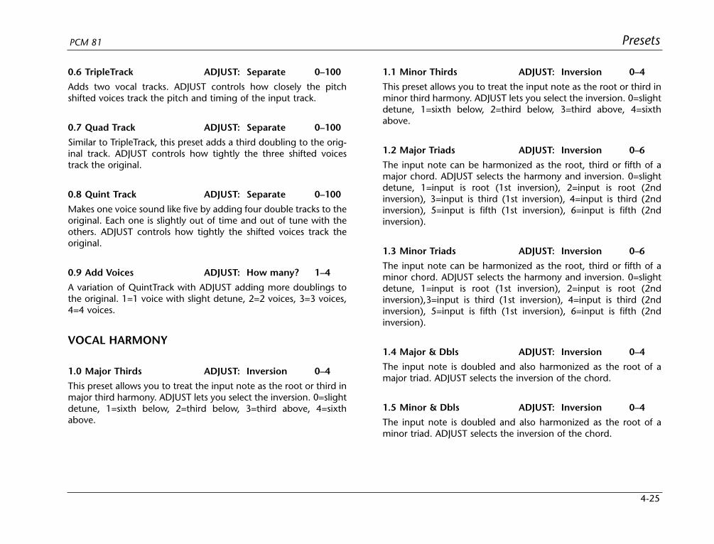
4-25
PresetsPCM 81
0.6 TripleTrack ADJUST: Separate 0–100
Adds two vocal tracks. ADJUST controls how closely the pitchshifted voices track the pitch and timing of the input track.
0.7 Quad Track ADJUST: Separate 0–100
Similar to TripleTrack, this preset adds a third doubling to the orig-inal track. ADJUST controls how tightly the three shifted voicestrack the original.
0.8 Quint Track ADJUST: Separate 0–100
Makes one voice sound like five by adding four double tracks to theoriginal. Each one is slightly out of time and out of tune with theothers. ADJUST controls how tightly the shifted voices track theoriginal.
0.9 Add Voices ADJUST: How many? 1–4
A variation of QuintTrack with ADJUST adding more doublings tothe original. 1=1 voice with slight detune, 2=2 voices, 3=3 voices,4=4 voices.
VOCAL HARMONY
1.0 Major Thirds ADJUST: Inversion 0–4
This preset allows you to treat the input note as the root or third inmajor third harmony. ADJUST lets you select the inversion. 0=slightdetune, 1=sixth below, 2=third below, 3=third above, 4=sixthabove.
1.1 Minor Thirds ADJUST: Inversion 0–4
This preset allows you to treat the input note as the root or third inminor third harmony. ADJUST lets you select the inversion. 0=slightdetune, 1=sixth below, 2=third below, 3=third above, 4=sixthabove.
1.2 Major Triads ADJUST: Inversion 0–6
The input note can be harmonized as the root, third or fifth of amajor chord. ADJUST selects the harmony and inversion. 0=slightdetune, 1=input is root (1st inversion), 2=input is root (2ndinversion), 3=input is third (1st inversion), 4=input is third (2ndinversion), 5=input is fifth (1st inversion), 6=input is fifth (2ndinversion).
1.3 Minor Triads ADJUST: Inversion 0–6
The input note can be harmonized as the root, third or fifth of aminor chord. ADJUST selects the harmony and inversion. 0=slightdetune, 1=input is root (1st inversion), 2=input is root (2ndinversion),3=input is third (1st inversion), 4=input is third (2ndinversion), 5=input is fifth (1st inversion), 6=input is fifth (2ndinversion).
1.4 Major & Dbls ADJUST: Inversion 0–4
The input note is doubled and also harmonized as the root of amajor triad. ADJUST selects the inversion of the chord.
1.5 Minor & Dbls ADJUST: Inversion 0–4
The input note is doubled and also harmonized as the root of aminor triad. ADJUST selects the inversion of the chord.
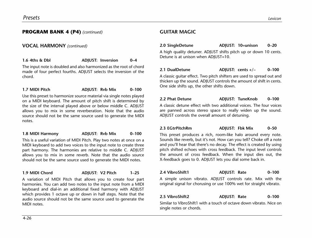
4-26
Presets Lexicon
PROGRAM BANK 4 (P4) (continued)
VOCAL HARMONY (continued)
1.6 4ths & Dbl ADJUST: Inversion 0–4
The input note is doubled and also harmonized as the root of chordmade of four perfect fourths. ADJUST selects the inversion of thechord.
1.7 MIDI Pitch ADJUST: Rvb Mix 0–100
Use this preset to harmonize source material via single notes playedon a MIDI keyboard. The amount of pitch shift is determined bythe size of the interval played above or below middle C. ADJUSTallows you to mix in some reverberation. Note that the audiosource should not be the same source used to generate the MIDInotes.
1.8 MIDI Harmony ADJUST: Rvb Mix 0–100
This is a useful variation of MIDI Pitch. Play two notes at once on aMIDI keyboard to add two voices to the input note to create threepart harmony. The harmonies are relative to middle C. ADJUSTallows you to mix in some reverb. Note that the audio sourceshould not be the same source used to generate the MIDI notes.
1.9 MIDI Chord ADJUST: V2 Pitch 1–25
A variation of MIDI Pitch that allows you to create four partharmonies. You can add two notes to the input note from a MIDIkeyboard and dial-in an additional fixed harmony with ADJUSTwhich provides 1 octave up or down in half steps. Note that theaudio source should not be the same source used to generate theMIDI notes.
GUITAR MAGIC
2.0 SingleDetune ADJUST: 10=unison 0–20
A high quality detuner. ADJUST shifts pitch up or down 10 cents.Detune is at unison when ADJUST=10.
2.1 DualDetune ADJUST: cents +/– 0–100
A classic guitar effect. Two pitch shifters are used to spread out andthicken up the sound. ADJUST controls the amount of shift in cents.One side shifts up, the other shifts down.
2.2 Phat Detune ADJUST: TuneKnob 0–100
A classic detune effect with two additional voices. The four voicesare panned across stereo space to really widen up the sound.ADJUST controls the overall amount of detuning.
2.3 EGtrPitchRm ADJUST: Fbk Mix 0–50
This preset produces a rich, room-like halo around every note.Sounds like reverb, but it’s not. How can you tell? Choke off a noteand you’ll hear that there’s no decay. The effect is created by usingpitch shifted echoes with cross feedback. The input level controlsthe amount of cross feedback. When the input dies out, theX-feedback goes to 0. ADJUST lets you dial some back in.
2.4 VibroShift1 ADJUST: Rate 0–100
A simple unison vibrato. ADJUST controls rate. Mix with theoriginal signal for chorusing or use 100% wet for straight vibrato.
2.5 VibroShift2 ADJUST: Rate 0–100
Similar to VibroShift1 with a touch of octave down vibrato. Nice onsingle notes or chords.
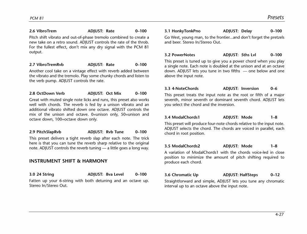
4-27
PresetsPCM 81
2.6 VibroTrem ADJUST: Rate 0–100
Pitch shift vibrato and out-of-phase tremolo combined to create anew take on a retro sound. ADJUST controls the rate of the throb.For the fullest effect, don’t mix any dry signal with the PCM 81output.
2.7 VibroTremRvb ADJUST: Rate 0–100
Another cool take on a vintage effect with reverb added betweenthe vibrato and the tremolo. Play some chunky chords and listen tothe verb pump. ADJUST controls the rate.
2.8 OctDown Verb ADJUST: Oct Mix 0–100
Great with muted single note licks and runs, this preset also workswell with chords. The reverb is fed by a unison vibrato and anadditional vibrato shifted down one octave. ADJUST controls themix of the unison and octave. 0=unison only, 50=unison andoctave down, 100=octave down only.
2.9 PitchSlapRvb ADJUST: Rvb Tune 0–100
This preset delivers a tight reverb slap after each note. The trickhere is that you can tune the reverb sharp relative to the originalnote. ADJUST controls the reverb tuning — a little goes a long way.
INSTRUMENT SHIFT & HARMONY
3.0 24 String ADJUST: 8va Level 0–100
Fatten up your 6-string with both detuning and an octave up.Stereo In/Stereo Out.
3.1 HonkyTonkPno ADJUST: Delay 0–100
Go West, young man, to the frontier...and don’t forget the pretzelsand beer. Stereo In/Stereo Out.
3.2 PowerNotes ADJUST: 5ths Lvl 0–100
This preset is tuned up to give you a power chord when you playa single note. Each note is doubled at the unison and at an octavedown. ADJUST lets you tune in two fifths — one below and oneabove the input note.
3.3 4-NoteChords ADJUST: Inversion 0–6
This preset treats the input note as the root or fifth of a majorseventh, minor seventh or dominant seventh chord. ADJUST letsyou select the chord and the inversion.
3.4 ModalChords1 ADJUST: Mode 1–8
This preset will produce four-note chords relative to the input note.ADJUST selects the chord. The chords are voiced in parallel, eachchord in root position.
3.5 ModalChords2 ADJUST: Mode 1–8
A variation of ModalChords1 with the chords voice-led in closeposition to minimize the amount of pitch shifting required toproduce each chord.
3.6 Chromatic Up ADJUST: HalfSteps 0–12
Straightforward and simple, ADJUST lets you tune any chromaticinterval up to an octave above the input note.
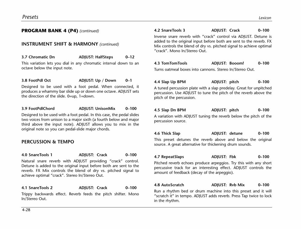
4-28
Presets Lexicon
PROGRAM BANK 4 (P4) (continued)
INSTRUMENT SHIFT & HARMONY (continued)
3.7 Chromatic Dn ADJUST: HalfSteps 0–12
This variation lets you dial in any chromatic interval down to anoctave below the input note.
3.8 FootPdl Oct ADJUST: Up / Down 0–1
Designed to be used with a foot pedal. When connected, itproduces a whammy bar slide up or down one octave. ADJUST setsthe direction of the slide. 0=up, 1=down.
3.9 FootPdlChord ADJUST: UnisonMix 0–100
Designed to be used with a foot pedal. In this case, the pedal slidestwo voices from unison to a major sixth (a fourth below and majorthird above the input note). ADJUST allows you to mix in theoriginal note so you can pedal-slide major chords.
PERCUSSION & TEMPO
4.0 SnareTools 1 ADJUST: Crack 0–100
Natural snare reverb with ADJUST providing “crack” control.Detune is added to the original input before both are sent to thereverb. FX Mix controls the blend of dry vs. pitched signal toachieve optimal “crack”. Stereo In/Stereo Out.
4.1 SnareTools 2 ADJUST: Crack 0–100
Trippy backwards effect. Reverb feeds the pitch shifter. MonoIn/Stereo Out.
4.2 SnareTools 3 ADJUST: Crack 0–100
Inverse snare reverb with “crack” control via ADJUST. Detune isadded to the original input before both are sent to the reverb. FXMix controls the blend of dry vs. pitched signal to achieve optimal“crack”. Mono In/Stereo Out.
4.3 TomTomTools ADJUST: Booom! 0–100
Turns oatmeal boxes into cannons. Stereo In/Stereo Out.
4.4 Slap Up BPM ADJUST: pitch 0–100
A tuned percussion plate with a slap predelay. Great for unpitchedpercussion. Use ADJUST to tune the pitch of the reverb above thepitch of the percussion.
4.5 Slap Dn BPM ADJUST: pitch 0–100
A variation with ADJUST tuning the reverb below the pitch of thepercussion source.
4.6 Thick Slap ADJUST: detune 0–100
This preset detunes the reverb above and below the originalsource. A great alternative for thickening drum sounds.
4.7 RepeatSlaps ADJUST: Fbk 0–100
Pitched reverb echoes produce arpeggios. Try this with any shortpercussive track for an interesting effect. ADJUST controls theamount of feedback (decay of the arpeggio).
4.8 AutoScratch ADJUST: Rvb Mix 0–100
Run a rhythm bed or drum machine into this preset and it will“scratch it” in tempo. ADJUST adds reverb. Press Tap twice to lockin the rhythm.
4-29
PresetsPCM 81
4.9 Stop n Go ADJUST: Rvb Mix 0–100
A more radical version of AutoScratch.
PROGRAM BANK 5 (P5)
SCI-FI FX
0.0 PullThePlug! ADJUST: Off/On 0–1
Use this special effect to simulate the sound of a tape machine, jukebox (etc.) running down when the power has been cut off in themiddle of a tune. Turn ADJUST from 1 to 0 to cut the power, andfrom 0 to 1 to turn it back on.
0.1 Stargate ADJUST: Velocity 0–100
A dramatic special effect that transforms a single percussive soundinto a spatial wash of ascending and descending pitches. Try thiswith single drum hits or short sound effect samples. ADJUSTcontrols the rate of the ascent/descent.
0.2 WhiteHole ADJUST: Big>Small 0–100
A variation of Stargate that transforms a single sonic event into arandomized series of pitched echoes. ADJUST controls the pitchand delay deviation.
0.3 MotherShip ADJUST: Velocity 0–100
Need some processing for lift-off or acceleration effects? This effectdelivers. Drive it with a single impulse or short sound effect toproduce a spatial glide that ascends to the limits of audibility.ADJUST controls the rate of ascent.
0.4 XplodeDown ADJUST: Velocity 0–100
Use this preset to add more drama to special effects (or even singledrum hits). This preset transforms the input source into an eeriedownward glide with ADJUST controlling the rate of the glide.
0.5 Xplode Up ADJUST: Velocity 0–100
A variation of XplodeDown with the input source transformed intoan upward glide.
0.6 DialogCloner ADJUST: Tuning 0–100
A special effect for speech, this preset creates the effect of severalpeople speaking at once. Four additional voices are added aboveand below the pitch of the input source. ADJUST controls thetuning spread of the four clones.
0.7 Toon Voices ADJUST: Character 0–7
Changes the character of vocals for special effect dialog tracks.ADJUST selects several different pitch shift amounts to create arange of characters from scary monsters, to chipmunks, to talkingbees.
0.8 Evil Voice ADJUST: Pitch 0–100
Downward pitch shift and a touch of reverb are used to turn anormal male speaking voice into something decidedly dark andnasty. ADJUST allows you to dial the appropriate touch of evil.
0.9 Evil Echoes ADJUST: Pitch 1–100
This special effect has echoes that change pitch as they repeat.ADJUST controls the amount of shift per repeat. 1-49=descendingpitch, 50=no pitch change, 51-100=ascending pitch.
4-30
Presets Lexicon
PROGRAM BANK 5 (P5) (continued)
PITCH & DELAY
1.0 Pitch Across ADJUST: Detune 0–100
A single note produces a 4-voice panned delay. ADJUST controlsthe amount of pitch shift for the four voices. Small values producedetuning. The maximum value (100) produces a major arpeggio.The delay rhythm is tempo-controlled. Press Tap twice to lock inwith the beat.
1.1 PitchEkoRvb ADJUST: Eko/Rvb 0–100
The dual pitch shifters produce a detune/echo effect with reverb.ADJUST lets you set the balance of the two effects. 0=detuneechoes only, 50=detune echoes and reverb, 100=reverb only.
1.2 PitchPong ADJUST: DelayRate 0–100
The inputs are delayed, pitched down a little, then cross fed to theother side. Slap echoes bounce from left to right and fall slightly inpitch. The LFO adds chorusing to the pitch change. StereoIn/Stereo Out.
1.3 AR DlyVerb ADJUST: Detune 0–100
When the input level drops, delays fade away into reverb. StereoIn/Stereo Out.
1.4 In The Air ADJUST: Go 0–1
The inputs are detuned + and - 8 cents. When ADJUST is changedfrom 0 to 1, a quarter-note delay recirculates through the detuner.Stereo In/Stereo Out.
1.5 Thick>Ducked ADJUST: Detune 0–100
The inputs are detuned. When the input level drops below thethreshold, quarter-note delays with regeneration recirculates intothe detuners. Stereo In/Stereo Out.
1.6 FootPdlEkos ADJUST: Detune 0–100
Designed to be used with a foot pedal. A detune chorus is routedthrough stereo delays and reverb. The pedal controls the inputlevel to the delays and reverb. Use the pedal to capture specificphrases in the delays/reverb. Great with guitar and other soloinstruments.
1.7 DualDTuneDly ADJUST: cents +/- 0–100
This preset combines two detuned voices with delays. ADJUSTcontrols the amount of detune. Controls for the delays (and reverbtoo) are in the Soft row.
1.8 QuaDTuneDly1 ADJUST: TuneKnob 0–100
For thicker detune and delay effects, this preset uses four pitchshifters for detuning. ADJUST controls the pitch spread of the fourshifters. Delay and reverb controls are in the Soft row.
1.9 QuaDTuneDly2 ADJUST: TuneKnob 0–100
Similar to QuadTuneDly1 with the delays set to rhythmic values(eighths and triplets). Press Tap to synchronize the rhythms to thebeat.
4-31
PresetsPCM 81
PITCH SEQUENCES
2.0 Major Across ADJUST: MasterDly 0–100
A major triad is arpeggiated across the stereo field. ADJUST controlsthe overall timing of the arpeggiation.
2.1 Minor Across ADJUST: MasterDly 0–100
A minor triad is arpeggiated across the stereo field. ADJUSTcontrols the overall timing of the arpeggiation.
2.2 Dim hARP ADJUST: GlissRate 0–100
The inputs rise in a diminished arpeggiated scale. This preset turnsone harp note into a glissando, or one quarter note into a harpchord. Individual voices are panned across the stereo field. StereoIn/Stereo Out.
2.3 Dim hARP Vrb ADJUST: GlissRate 0–100
Similar to Dim hARP with an added reverb.
2.4 DimScaleDown ADJUST: ScaleRate 0–100
The inputs descend into a diminished arpeggiated scale. Thispreset turns one note into a scale or glissando. Individual voices arepanned across the stereo spectrum. A little reverb is added.
2.5 GlassCascade ADJUST: MasterDly 0-100
A glassy, chime-like tail makes this preset great for sustainedsingle-note melodies. Spooky and pretty at the same time. StereoIn/Stereo Out.
2.6 Carnival ADJUST: MstrFdbk 0–100
Turns guitar or piano into steel drums, especially if you playdiatonic thirds, as steel drummers have been known to do. StereoIn/Stereo Out.
2.7 Sequence 1 ADJUST: MasterFbk 0–100
Play single note lines. Adds M6 and M9. Tap tempo-driven. StereoIn/Stereo Out.
2.8 Sequence 2 ADJUST: MasterFbk 0–100
Similar to Sequence1 with a very different sound.
2.9 Pentatonics! ADJUST: MasterFbk 0-100
A sequence of notes from the minor pentatonic scale are played foreach input note. The input note is treated as the root of the scale.ADJUST controls the amount of feedback.
PADS & DRONES
3.0 JurassicSolo ADJUST: Decay 0–100
A very long plate reverb is pitched down a minor third. Spooky.Good for single-note melody soundtracks. Stereo In/Stereo Out.
3.1 SwrlWhlNt ADJUST: MasterDly 0–100
Swirling Whole Note — An LFO controls FX Width. FX Mix is 100%reverb. Delay time is 0ms. Slightly detuned swirling voices producea reverb that is especially wonderful on whole notes. StereoIn/Stereo Out.
4-32
Presets Lexicon
PROGRAM BANK 5 (P5) (continued)
PADS & DRONES (continued)
3.2 Sweet Chorus ADJUST: Spd/Width 0–100
An LFO sine wave alternates detuning from positive to negativepitch values. The pitch of both outputs is positive, then negative.ADJUST changes both the speed and width of detuning(faster=wider). Stereo In/Stereo Out.
3.3 MirrorChorus ADJUST: Speed 0–100
An LFO square wave alternates detuning from positive to negativepitch values. The pitch shift of the left output is the opposite of theright. Stereo In/Stereo Out.
3.4 LFO Detune ADJUST: Detune 0–100
A slow, chorusy detuner. Stereo In/Stereo Out.
3.5 SpatialDuck ADJUST: cents +/– 0–100
This preset produces a wash of detuned echoes with long reverbdecay. The reverb OutWidth is modulated to create spatialmovement. The entire effect is ducked by input level. (The reverband echo decays increase as the level fades.) ADJUST controls theamount of detuning.
3.6 Vibrato BPM ADJUST: Depth 0–100
The vibrato produced by this effect is tempo controlled so it can besynchronized to the beat. ADJUST sets the vibrato depth. Press Taptwice to lock-in the tempo.
3.7 Verbato ADJUST: Depth 0–100
In this preset, a small stereo chamber reverb is routed through thestereo pitch shifter. The pitch shifter is set to create vibrato. A niceway to thicken up a track without messing with the dry sound.
UTILITY PROGRAMS
3.8 Stereo VSO ADJUST: Rvb Mix 0–100
Use this preset for pitch correcting stereo off-speed playbackmaterial. Set the Varispeed parameter (in the first position of theSoft row) to match the amount of varispeed used for playback.ADJUST controls the amount of reverb added to the correctedaudio.
3.9 Mono VSO ADJUST: Rvb Mix 0–100
Use this preset for pitch correcting mono off-speed playbackmaterial. Set the Varispeed parameter (in the first position of theSoft row) to match the amount of varispeed used for playbackADJUST controls the amount of reverb added to the correctedaudio.
PITCH CORRECTWIth the exception of Demo Correct (4.9), all of the presets aredesigned to accept a mono vocal track on either (or both) inputs.Note also that , in each preset , the reverb is turned off and all pitchparameters that are not patched can be found in the Soft Row.
4-33
PresetsPCM 81
4.0 VoxFix E2>C6 ADJUST: On/Off 0-1This preset is set up to be used with a MIDI controller with akeyboard, pitch bender and sustain pedal. It provides threedifferent methods to correct pitch problems. You can: use thebender to change the pitch "on the fly," use the sustain pedal toturn correction on and off, or fix a bad note by playing the correctone on the keyboard. Press Edit to see the notes displayed. ADJUSTis patched to turn correction on and off. All of the pitchparameters that aren't patched are in the Soft Row. Low Note andHigh Note are tuned to the full vocal range (E2 through C6).
4.1 VoxFix Bass ADJUST: On/Off 0-1
The same as VoxFix E2>C6, except that it is tuned to the bass range(E2-A4).
4.2 VoxFix Tenor ADJUST: On/Off 0-1
The same as VoxFix E2>C6, except that it is tuned to the tenorrange (C3-C5).
4.3 VoxFix Alto ADJUST: On/Off 0-1
The same as VoxFix E2>C6, except that it is tuned to the alto range(F3-F5).
4.4 VoxFix Sprno ADJUST: On/Off 0-1
The same as VoxFix E2>C6, except that it is tuned to the sopranorange (C4-C6).
4.5 KnobCentsUp ADJUST: Sharp 0–100
For tracks that are consistently flat. Use ADJUST to tune the trackup, and a MIDI keyboard to fix bad notes.
4.6 KnobCentsDN ADJUST: Flat 0-100
For tracks that are consistently sharp. Use ADJUST to tune the trackdown, and a MIDI keyboard to fix bad notes.
4.7 Double Effect ADJUST: On/Off 0-1
This preset produces an alternative double track effect. Mix theoutput of the PCM 81 with the original vocal track. Use ADJUST torandomize the amount of delay and pitch difference between theoriginal and processed tracks.
4.8 Knob Freeze ADJUST: On/Off 0–1
This one is a special effect. Turn ADJUST from 0 to 1 to freeze thepitch of the vocal track to whatever was being sung when the knobwas turned. Turn it back down to 0 to release the pitch. Mixed withthe original, this creates drone-like harmonies. By itself, this effectis a new take on “robot” voices.
4.9 Demo Correct ADJUST: unused
This preset is for demonstration use. The left input is turned off andall the pitch parameters are in the Soft Row.
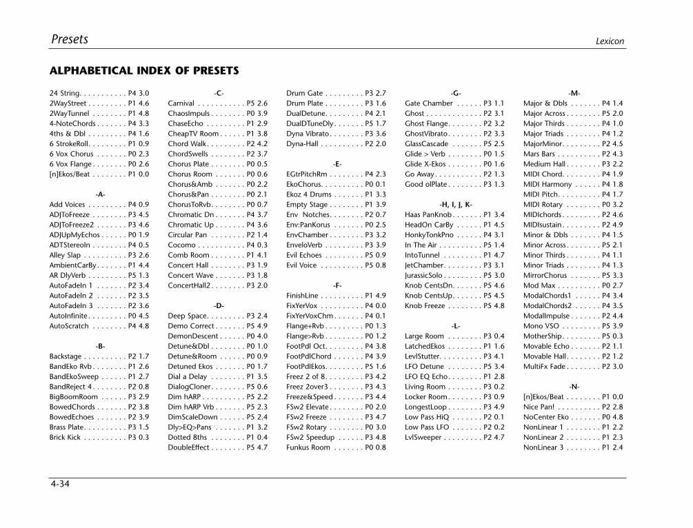
4-34
Presets Lexicon
24 String. . . . . . . . . . . P4 3.02WayStreet . . . . . . . . . P1 4.62WayTunnel . . . . . . . . P1 4.84-NoteChords . . . . . . . P4 3.34ths & Dbl . . . . . . . . . P4 1.66 StrokeRoll. . . . . . . . . P1 0.96 Vox Chorus . . . . . . . P0 2.36 Vox Flange . . . . . . . . P0 2.6[n]Ekos/Beat . . . . . . . . P1 0.0
-A-Add Voices . . . . . . . . . P4 0.9ADJToFreeze . . . . . . . . P3 4.5ADJToFreeze2 . . . . . . . P3 4.6ADJUpMyEchos . . . . . . P0 1.9ADTStereoIn . . . . . . . . P4 0.5Alley Slap . . . . . . . . . . P3 2.6AmbientCarBy . . . . . . . P1 4.4AR DlyVerb . . . . . . . . . P5 1.3AutoFadeIn 1 . . . . . . . P2 3.4AutoFadeIn 2 . . . . . . . P2 3.5AutoFadeIn 3 . . . . . . . P2 3.6AutoInfinite . . . . . . . . . P0 4.5AutoScratch . . . . . . . . P4 4.8
-B-Backstage . . . . . . . . . . P2 1.7BandEko Rvb . . . . . . . . P1 2.6BandEkoSweep . . . . . . P1 2.7BandReject 4 . . . . . . . . P2 0.8BigBoomRoom . . . . . . P3 2.9BowedChords . . . . . . . P2 3.8BowedEchoes . . . . . . . P2 3.9Brass Plate. . . . . . . . . . P3 1.5Brick Kick . . . . . . . . . . P3 0.3
-C-Carnival . . . . . . . . . . . P5 2.6ChaosImpuls . . . . . . . . P0 3.9ChaseEcho . . . . . . . . . P1 2.9CheapTV Room . . . . . . P1 3.8Chord Walk. . . . . . . . . P2 4.2ChordSwells . . . . . . . . P2 3.7Chorus Plate . . . . . . . . P0 0.5Chorus Room . . . . . . . P0 0.6Chorus&Amb . . . . . . . P0 2.2Chorus&Pan . . . . . . . . P0 2.1ChorusToRvb. . . . . . . . P0 0.7Chromatic Dn . . . . . . . P4 3.7Chromatic Up . . . . . . . P4 3.6Circular Pan . . . . . . . . P2 1.4Cocomo . . . . . . . . . . . P4 0.3Comb Room . . . . . . . . P1 4.1Concert Hall . . . . . . . . P3 1.9Concert Wave . . . . . . . P3 1.8ConcertHall2 . . . . . . . . P3 2.0
-D-Deep Space. . . . . . . . . P3 2.4Demo Correct . . . . . . . P5 4.9DemonDescent . . . . . . P0 4.0Detune&Dbl . . . . . . . . P0 1.0Detune&Room . . . . . . P0 0.9Detuned Ekos . . . . . . . P0 1.7Dial a Delay . . . . . . . . P1 3.5DialogCloner. . . . . . . . P5 0.6Dim hARP . . . . . . . . . . P5 2.2Dim hARP Vrb . . . . . . . P5 2.3DimScaleDown . . . . . . P5 2.4Dly>EQ>Pans . . . . . . . P1 3.2Dotted 8ths . . . . . . . . P1 0.4DoubleEffect . . . . . . . . P5 4.7
Drum Gate . . . . . . . . . P3 2.7Drum Plate . . . . . . . . . P3 1.6DualDetune. . . . . . . . . P4 2.1DualDTuneDly . . . . . . . P5 1.7Dyna Vibrato. . . . . . . . P3 3.6Dyna-Hall . . . . . . . . . . P2 2.0
-E-EGtrPitchRm . . . . . . . . P4 2.3EkoChorus. . . . . . . . . . P0 0.1Ekoz 4 Drums . . . . . . . P1 3.3Empty Stage . . . . . . . . P1 3.9Env Notches. . . . . . . . P2 0.7Env:PanKorus . . . . . . . P0 2.5EnvChamber . . . . . . . . P3 3.2EnveloVerb . . . . . . . . . P3 3.9Evil Echoes . . . . . . . . . P5 0.9Evil Voice . . . . . . . . . . P5 0.8
-F-FinishLine . . . . . . . . . . P1 4.9FixYerVox . . . . . . . . . . P4 0.0FixYerVoxChm. . . . . . . P4 0.1Flange+Rvb . . . . . . . . . P0 1.3Flange>Rvb . . . . . . . . . P0 1.2FootPdl Oct. . . . . . . . . P4 3.8FootPdlChord . . . . . . . P4 3.9FootPdlEkos. . . . . . . . . P5 1.6Freez 2 of 8. . . . . . . . . P3 4.2Freez 2over3 . . . . . . . . P3 4.3Freeze&Speed . . . . . . . P3 4.4FSw2 Elevate . . . . . . . . P0 2.0FSw2 Freeze . . . . . . . . P3 4.7FSw2 Rotary . . . . . . . . P0 3.0FSw2 Speedup . . . . . . P3 4.8Funkus Room . . . . . . . P0 0.8
-G-Gate Chamber . . . . . . P3 1.1Ghost . . . . . . . . . . . . . P2 3.1Ghost Flange. . . . . . . . P2 3.2GhostVibrato. . . . . . . . P2 3.3GlassCascade . . . . . . . P5 2.5Glide > Verb . . . . . . . . P0 1.5Glide X-Ekos . . . . . . . . P0 1.6Go Away. . . . . . . . . . . P2 1.3Good olPlate . . . . . . . . P3 1.3
-H, I, J, K-Haas PanKnob . . . . . . . P1 3.4HeadOn CarBy . . . . . . P1 4.5HonkyTonkPno . . . . . . P4 3.1In The Air . . . . . . . . . . P5 1.4IntoTunnel . . . . . . . . . P1 4.7JetChamber. . . . . . . . . P3 3.1JurassicSolo . . . . . . . . . P5 3.0Knob CentsDn. . . . . . . P5 4.6Knob CentsUp. . . . . . . P5 4.5Knob Freeze . . . . . . . . P5 4.8
-L-Large Room . . . . . . . . P3 0.4LatchedEkos . . . . . . . . P1 1.6LevlStutter. . . . . . . . . . P3 4.1LFO Detune . . . . . . . . P5 3.4LFO EQ Echo. . . . . . . . P1 2.8Living Room . . . . . . . . P3 0.2Locker Room. . . . . . . . P3 0.9LongestLoop . . . . . . . . P3 4.9Low Pass HiQ . . . . . . . P2 0.1Low Pass LFO . . . . . . . P2 0.2LvlSweeper . . . . . . . . . P2 4.7
-M-Major & Dbls . . . . . . . P4 1.4Major Across . . . . . . . . P5 2.0Major Thirds . . . . . . . . P4 1.0Major Triads . . . . . . . . P4 1.2MajorMinor. . . . . . . . . P2 4.5Mars Bars . . . . . . . . . . P2 4.3Medium Hall . . . . . . . . P3 2.2MIDI Chord. . . . . . . . . P4 1.9MIDI Harmony . . . . . . P4 1.8MIDI Pitch. . . . . . . . . . P4 1.7MIDI Rotary . . . . . . . . P0 3.2MIDIchords . . . . . . . . . P2 4.6MIDIsustain. . . . . . . . . P2 4.9Minor & Dbls . . . . . . . P4 1.5Minor Across . . . . . . . . P5 2.1Minor Thirds . . . . . . . . P4 1.1Minor Triads . . . . . . . . P4 1.3MirrorChorus . . . . . . . P5 3.3Mod Max . . . . . . . . . . P0 2.7ModalChords1 . . . . . . P4 3.4ModalChords2 . . . . . . P4 3.5ModalImpulse . . . . . . . P2 4.4Mono VSO . . . . . . . . . P5 3.9MotherShip. . . . . . . . . P5 0.3Movable Echo . . . . . . . P2 1.1Movable Hall. . . . . . . . P2 1.2MultiFx Fade . . . . . . . . P2 3.0
-N-[n]Ekos/Beat . . . . . . . . P1 0.0Nice Pan! . . . . . . . . . . P2 2.8NoCenter Eko . . . . . . . P0 4.8NonLinear 1 . . . . . . . . P1 2.2NonLinear 2 . . . . . . . . P1 2.3NonLinear 3 . . . . . . . . P1 2.4
ALPHABETICAL INDEX OF PRESETS
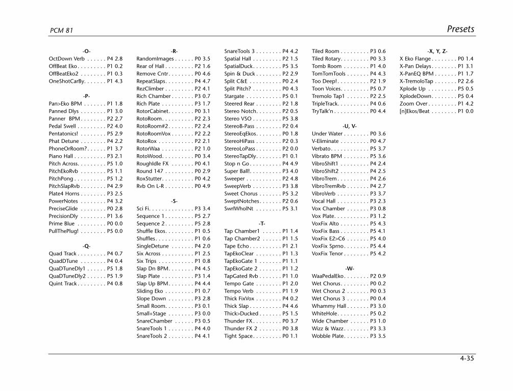
4-35
PresetsPCM 81
-O-OctDown Verb . . . . . . P4 2.8OffBeat Eko . . . . . . . . . P1 0.2OffBeatEko2 . . . . . . . . P1 0.3OneShotCarBy. . . . . . . P1 4.3
-P-Pan>Eko BPM . . . . . . . P1 1.8Panned Dlys . . . . . . . . P1 3.0Panner BPM . . . . . . . . P2 2.7Pedal Swell . . . . . . . . . P2 4.0Pentatonics! . . . . . . . . P5 2.9Phat Detune . . . . . . . . P4 2.2PhoneOrRoom?. . . . . . P1 3.7Piano Hall . . . . . . . . . . P3 2.1Pitch Across. . . . . . . . . P5 1.0PitchEkoRvb . . . . . . . . P5 1.1PitchPong . . . . . . . . . . P5 1.2PitchSlapRvb . . . . . . . . P4 2.9Plate4 Horns . . . . . . . . P3 2.5PowerNotes . . . . . . . . P4 3.2PreciseGlide . . . . . . . . P0 2.8PrecisionDly . . . . . . . . P1 3.6Prime Blue . . . . . . . . . P0 0.0PullThePlug! . . . . . . . . P5 0.0
-Q-Quad Track . . . . . . . . . P4 0.7QuadDTune . . . . . . . . P4 0.4QuaDTuneDly1 . . . . . . P5 1.8QuaDTuneDly2 . . . . . . P5 1.9Quint Track . . . . . . . . . P4 0.8
-R-RandomImages . . . . . . P0 3.5Rear of Hall . . . . . . . . . P2 1.6Remove Cntr . . . . . . . . P0 4.6RepeatSlaps. . . . . . . . . P4 4.7RezClimber . . . . . . . . . P2 4.1Rich Chamber . . . . . . . P3 0.7Rich Plate . . . . . . . . . . P3 1.7RotorCabinet. . . . . . . . P0 3.1RotoRoom. . . . . . . . . . P2 2.3RotoRoom#2. . . . . . . . P2 2.4RotoRoomVox . . . . . . . P2 2.2RotoRox . . . . . . . . . . . P2 2.1RotorWaa . . . . . . . . . . P2 1.0RotoWood. . . . . . . . . . P0 3.4RoughIdle FX . . . . . . . P0 4.1Round 147 . . . . . . . . . P0 2.9RoxStutter. . . . . . . . . . P0 4.2Rvb On L-R . . . . . . . . . P0 4.9
-S-Sci Fi. . . . . . . . . . . . . . P3 3.4Sequence 1 . . . . . . . . . P5 2.7Sequence 2 . . . . . . . . . P5 2.8Shuffle Ekos. . . . . . . . . P1 0.5Shuffles. . . . . . . . . . . . P1 0.6SingleDetune . . . . . . . P4 2.0Six Across . . . . . . . . . . P1 2.5Six Trips . . . . . . . . . . . P1 0.8Slap Dn BPM. . . . . . . . P4 4.5Slap Plate . . . . . . . . . . P3 1.4Slap Up BPM. . . . . . . . P4 4.4Sliding Eko . . . . . . . . . P1 0.7Slope Down . . . . . . . . P3 2.8Small Room. . . . . . . . . P3 0.1Small+Stage . . . . . . . . P3 0.0SnareChamber . . . . . . P3 0.5SnareTools 1 . . . . . . . . P4 4.0SnareTools 2 . . . . . . . . P4 4.1
SnareTools 3 . . . . . . . . P4 4.2Spatial Hall . . . . . . . . . P2 1.5SpatialDuck. . . . . . . . . P5 3.5Spin & Duck . . . . . . . . P2 2.9Split C&E . . . . . . . . . . P0 2.4Split Pitch? . . . . . . . . . P0 4.3Stargate . . . . . . . . . . . P5 0.1Steered Rear . . . . . . . . P2 1.8Stereo Notch. . . . . . . . P2 0.5Stereo VSO . . . . . . . . . P5 3.8StereoB-Pass . . . . . . . . P2 0.4StereoEqEkos. . . . . . . . P0 1.8StereoHiPass . . . . . . . . P2 0.3StereoLoPass . . . . . . . . P2 0.0StereoTapDly. . . . . . . . P1 0.1Stop n Go . . . . . . . . . . P4 4.9Super Ball!. . . . . . . . . . P3 4.0Sweeper . . . . . . . . . . . P2 4.8SweepVerb . . . . . . . . . P3 3.8Sweet Chorus . . . . . . . P5 3.2SweptNotches. . . . . . . P2 0.6SwrlWholNt . . . . . . . . P5 3.1
-T-Tap Chamber1 . . . . . . P1 1.4Tap Chamber2 . . . . . . P1 1.5Tape Echo . . . . . . . . . . P1 2.1TapEkoClear . . . . . . . . P1 1.3TapEkoGate 1 . . . . . . . P1 1.1TapEkoGate 2 . . . . . . . P1 1.2TapGated Rvb . . . . . . . P1 1.0Tempo Gate . . . . . . . . P1 2.0Tempo Verb . . . . . . . . P1 1.9Thick FixVox . . . . . . . . P4 0.2Thick Slap . . . . . . . . . . P4 4.6Thick>Ducked . . . . . . . P5 1.5Thunder FX. . . . . . . . . P0 3.7Thunder FX 2 . . . . . . . P0 3.8Tight Space. . . . . . . . . P0 1.1
Tiled Room . . . . . . . . . P3 0.6Tiled Rotary. . . . . . . . . P0 3.3Tomb Room . . . . . . . . P1 4.0TomTomTools . . . . . . . P4 4.3Too Deep! . . . . . . . . . . P2 1.9Toon Voices. . . . . . . . . P5 0.7Tremolo Tap1 . . . . . . . P2 2.5TripleTrack. . . . . . . . . . P4 0.6TryTalk’n . . . . . . . . . . . P0 4.4
-U, V-Under Water . . . . . . . . P0 3.6V-Eliminate . . . . . . . . . P0 4.7Verbato. . . . . . . . . . . . P5 3.7Vibrato BPM . . . . . . . . P5 3.6VibroShift1 . . . . . . . . . P4 2.4VibroShift2 . . . . . . . . . P4 2.5VibroTrem . . . . . . . . . . P4 2.6VibroTremRvb . . . . . . . P4 2.7VibroVerb . . . . . . . . . . P3 3.7Vocal Hall . . . . . . . . . . P3 2.3Vox Chamber . . . . . . . P3 0.8Vox Plate. . . . . . . . . . . P3 1.2VoxFix Alto . . . . . . . . . P5 4.3VoxFix Bass . . . . . . . . . P5 4.1VoxFix E2>C6 . . . . . . . P5 4.0VoxFix Sprno. . . . . . . . P5 4.4VoxFix Tenor . . . . . . . . P5 4.2
-W-WaaPedalEko. . . . . . . . P2 0.9Wet Chorus. . . . . . . . . P0 0.2Wet Chorus 2 . . . . . . . P0 0.3Wet Chorus 3 . . . . . . . P0 0.4Whammy Hall . . . . . . . P3 3.0WhiteHole. . . . . . . . . . P5 0.2Wide Chamber . . . . . . P3 1.0Wizz & Wazz . . . . . . . . P3 3.3Wobble Plate. . . . . . . . P3 3.5
-X, Y, Z-X Eko Flange . . . . . . . . P0 1.4X-Pan Delays . . . . . . . . P1 3.1X-PanEQ BPM . . . . . . . P1 1.7X-TremoloTap . . . . . . . P2 2.6Xplode Up . . . . . . . . . P5 0.5XplodeDown. . . . . . . . P5 0.4Zoom Over . . . . . . . . . P1 4.2[n]Ekos/Beat . . . . . . . . P1 0.0
MIDI Operation
5Selecting a MIDI Channel..............................................................5-2
Accessing Programs and Registers.................................................5-2
Controlling Tempo Rate with MIDI Clock......................................5-3MIDI Tempo Control • Using the PCM 81 as a MIDI Clock Source • Slaving Twoor More PCM 81s
Controller Quirks...........................................................................5-4
The ADJUST Knob, Foot Pedal, Foot Sw 1, and Foot Sw 2 as MIDI Controllers.......................................................5-4
Controlling the Soft Knob with MIDI • Controlling the Soft Knob with a FootPedal
Program Change Messages...........................................................5-5
Automation...................................................................................5-6SysEx Automation • Controller Automation • Reset All Controllers • MIDI Clockand Clock Commands • PCM 90 Compatibility • Dynamic MIDI
Bulk Data Dumps..........................................................................5-8
MIDI Implementation Chart ..........................................................5-8

5-2
MIDI Operation Lexicon
SELECTING A MIDI CHANNELAll PCM 81 parameters, programs and registers can be accessed byMIDI. All MIDI applications require the PCM 81 to be connectedwith one or more MIDI devices with standard MIDI cables via therear panel MIDI jacks.
MIDI controls, such as Transmit and Receive Channel selection areavailable in Control mode Row 3 MIDI. All of these controls aredescribed in Chapter 2. Several are repeated here for yourconvenience.
Before using the PCM 81 with other MIDI devices, all devices mustbe set to the same MIDI channel. To set the PCM 81 to receive MIDI:
1. Set the controller you will be using (keyboard, sequencer, otherPCM 81, etc.) to transmit on any MIDI channel (1-16).
2. On the PCM 81, press Control. Use Select and Up and Downto locate matrix position 3.1 Receive.
3. Turn ADJUST to select OFF, 1-16, or OMNI for receipt of MIDImessages.
ACCESSING PROGRAMS AND REGISTERSSome extremely useful effects can be created by controlling PCM81 parameters remotely in real time. Almost all of the controllersfound on a MIDI keyboard or MIDI foot controller (pitch benders,mod wheels, sliders, switches, breath controllers, foot pedals andfootswitches) can be used to adjust PCM 81 parameters. We referto this real time remote control capability as Dynamic MIDI®.
Sending a MIDI Program Change message (0-49) from the con-troller will load the corresponding PCM 81 register. If any MIDIsources are active as global or general purpose patches, movingthe appropriate control on the controller will cause the patcheddestination parameter to change. (See Patching.) If you want touse Dynamic MIDI, but don’t want the PCM 81 to load new regis-ters when you change programs on your controller, set your con-troller so that it doesn’t transmit Program Change messages, or setPCM 81 MIDI Program Change to Off at Control mode matrix loca-tion 3.3.
MIDIFOOT
SWITCHL R
INMIDI
AES/EBU
THRU OUT
OUT IN
FOOTCONTROLLER
BALANCED OUTPUTS
INPUTSBALANCED
INPUTLEVELL R
S/PDIF
IN
OUT
UNBAL-20dB
0dB
PUSHPUSHPUSHPUSH PUSHPUSH
MIDI Out
MIDI In
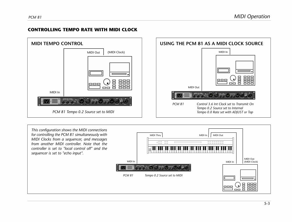
5-3
MIDI OperationPCM 81
CONTROLLING TEMPO RATE WITH MIDI CLOCK
MIDI TEMPO CONTROL USING THE PCM 81 AS A MIDI CLOCK SOURCE
MIDIFOOT
SWITCHL R
INMIDI
AES/EBU
THRU OUT
OUT IN
FOOTCONTROLLER
BALANCED OUTPUTS
INPUTSBALANCED
INPUTLEVELL R
S/PDIF
IN
OUT
UNBAL-20dB
0dB
PUSHPUSHPUSHPUSH PUSHPUSH
MIDI Out (MIDI Clock)
MIDI In
PCM 81 Tempo 0.2 Source set to MIDI
MIDIFOOT
SWITCHL R
INMIDI
AES/EBU
THRU OUT
OUT IN
FOOTCONTROLLER
BALANCED OUTPUTS
INPUTSBALANCED
INPUTLEVELL R
S/PDIF
IN
OUT
UNBAL-20dB
0dB
PUSHPUSHPUSHPUSH PUSHPUSH
MIDI In
MIDI Out
PCM 81 Control 3.6 Int Clock set to Transmit OnTempo 0.2 Source set to InternalTempo 0.0 Rate set with ADJUST or Tap
MIDIFOOT
SWITCHL R
INMIDI
AES/EBU
THRU OUT
OUT IN
FOOTCONTROLLER
BALANCED OUTPUTS
INPUTSBALANCED
INPUTLEVELL R
S/PDIF
IN
OUT
UNBAL-20dB
0dB
PUSHPUSHPUSHPUSH PUSHPUSH
MIDI Thru MIDI In MIDI Out
MIDI InMIDI Out(MIDI Clock)MIDI In
PCM 81 Tempo 0.2 Source set to MIDI
This configuration shows the MIDI connectionsfor controlling the PCM 81 simultaneously withMIDI Clocks from a sequencer, and messagesfrom another MIDI controller. Note that thecontroller is set to "local control off" and thesequencer is set to "echo input".
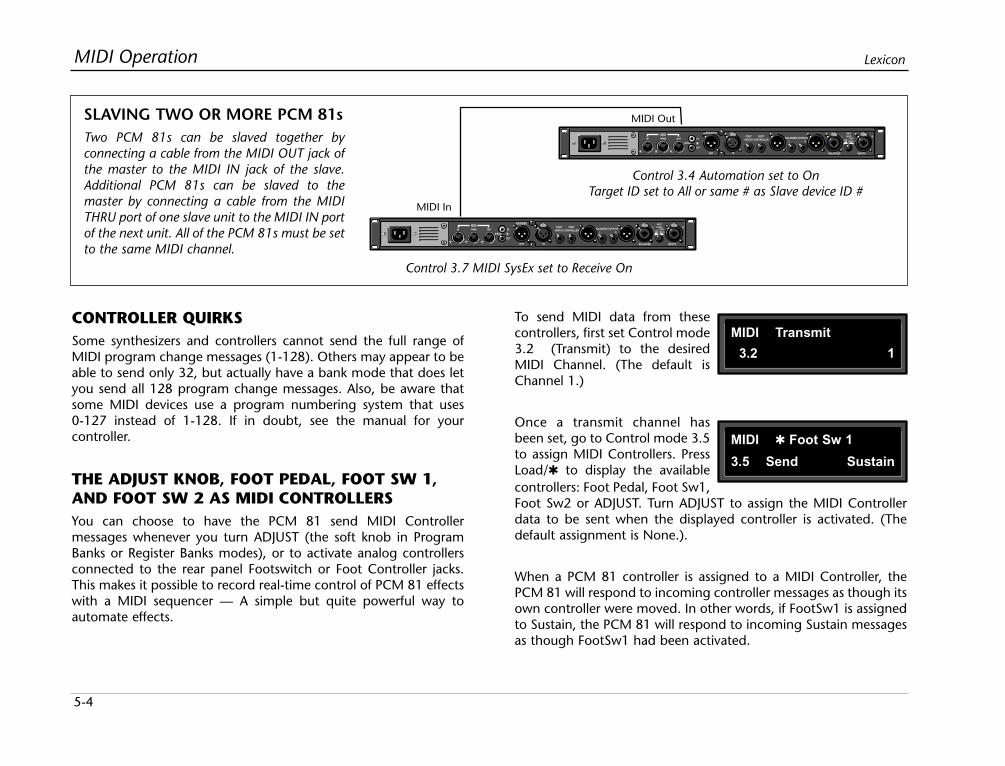
5-4
MIDI Operation Lexicon
CONTROLLER QUIRKSSome synthesizers and controllers cannot send the full range ofMIDI program change messages (1-128). Others may appear to beable to send only 32, but actually have a bank mode that does letyou send all 128 program change messages. Also, be aware thatsome MIDI devices use a program numbering system that uses0-127 instead of 1-128. If in doubt, see the manual for yourcontroller.
THE ADJUST KNOB, FOOT PEDAL, FOOT SW 1,AND FOOT SW 2 AS MIDI CONTROLLERSYou can choose to have the PCM 81 send MIDI Controllermessages whenever you turn ADJUST (the soft knob in ProgramBanks or Register Banks modes), or to activate analog controllersconnected to the rear panel Footswitch or Foot Controller jacks.This makes it possible to record real-time control of PCM 81 effectswith a MIDI sequencer — A simple but quite powerful way toautomate effects.
MIDIFOOT
SWITCHL R
INMIDI
AES/EBU
THRU OUT
OUT IN
FOOTCONTROLLER
BALANCED OUTPUTS
INPUTSBALANCED
INPUTLEVELL R
S/PDIF
IN
OUT
UNBAL-20dB
0dB
PUSHPUSHPUSHPUSH PUSHPUSH
MIDIFOOT
SWITCHL R
INMIDI
AES/EBU
THRU OUT
OUT IN
FOOTCONTROLLER
BALANCED OUTPUTS
INPUTSBALANCED
INPUTLEVELL R
S/PDIF
IN
OUT
UNBAL-20dB
0dB
PUSHPUSHPUSHPUSH PUSHPUSH
MIDI Out
MIDI In
Control 3.7 MIDI SysEx set to Receive On
Control 3.4 Automation set to OnTarget ID set to All or same # as Slave device ID #
SLAVING TWO OR MORE PCM 81sTwo PCM 81s can be slaved together byconnecting a cable from the MIDI OUT jack ofthe master to the MIDI IN jack of the slave.Additional PCM 81s can be slaved to themaster by connecting a cable from the MIDITHRU port of one slave unit to the MIDI IN portof the next unit. All of the PCM 81s must be setto the same MIDI channel.
To send MIDI data from thesecontrollers, first set Control mode3.2 (Transmit) to the desiredMIDI Channel. (The default isChannel 1.)
Once a transmit channel hasbeen set, go to Control mode 3.5to assign MIDI Controllers. PressLoad/ to display the availablecontrollers: Foot Pedal, Foot Sw1,Foot Sw2 or ADJUST. Turn ADJUST to assign the MIDI Controllerdata to be sent when the displayed controller is activated. (Thedefault assignment is None.).
When a PCM 81 controller is assigned to a MIDI Controller, thePCM 81 will respond to incoming controller messages as though itsown controller were moved. In other words, if FootSw1 is assignedto Sustain, the PCM 81 will respond to incoming Sustain messagesas though FootSw1 had been activated.
MIDI Transmit
3.2 1
MIDI Foot Sw 1
3.5 Send Sustain
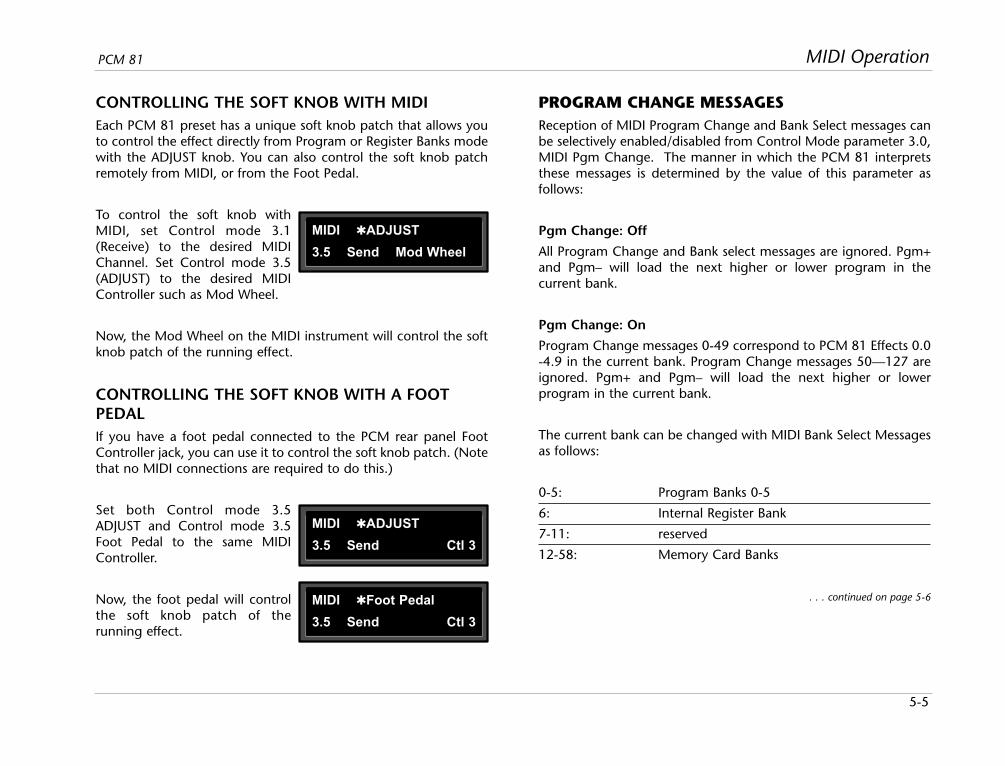
5-5
MIDI OperationPCM 81
CONTROLLING THE SOFT KNOB WITH MIDIEach PCM 81 preset has a unique soft knob patch that allows youto control the effect directly from Program or Register Banks modewith the ADJUST knob. You can also control the soft knob patchremotely from MIDI, or from the Foot Pedal.
To control the soft knob withMIDI, set Control mode 3.1(Receive) to the desired MIDIChannel. Set Control mode 3.5(ADJUST) to the desired MIDIController such as Mod Wheel.
Now, the Mod Wheel on the MIDI instrument will control the softknob patch of the running effect.
CONTROLLING THE SOFT KNOB WITH A FOOTPEDALIf you have a foot pedal connected to the PCM rear panel FootController jack, you can use it to control the soft knob patch. (Notethat no MIDI connections are required to do this.)
Set both Control mode 3.5ADJUST and Control mode 3.5Foot Pedal to the same MIDIController.
Now, the foot pedal will controlthe soft knob patch of therunning effect.
PROGRAM CHANGE MESSAGESReception of MIDI Program Change and Bank Select messages canbe selectively enabled/disabled from Control Mode parameter 3.0,MIDI Pgm Change. The manner in which the PCM 81 interpretsthese messages is determined by the value of this parameter asfollows:
Pgm Change: Off
All Program Change and Bank select messages are ignored. Pgm+and Pgm– will load the next higher or lower program in thecurrent bank.
Pgm Change: On
Program Change messages 0-49 correspond to PCM 81 Effects 0.0-4.9 in the current bank. Program Change messages 50—127 areignored. Pgm+ and Pgm– will load the next higher or lowerprogram in the current bank.
The current bank can be changed with MIDI Bank Select Messagesas follows:
0-5: Program Banks 0-5
6: Internal Register Bank
7-11: reserved
12-58: Memory Card Banks
. . . continued on page 5-6
MIDI ADJUST
3.5 Send Mod Wheel
MIDI ADJUST
3.5 Send Ctl 3
MIDI Foot Pedal
3.5 Send Ctl 3

5-6
MIDI Operation Lexicon
The number of banks available on a given card will vary with cardsize as follows:
Card Size Banks
64 2
256 11
512 23
1 Meg 47
Pgm Change: Map
Program Change 0-127 can be mapped to any PCM 81 Effect inany internal or card bank. Two 128 element maps are storedinternally, additional maps may be stored on RAM cards.
Map 0 Map 1
MIDI 0 = P0 0.0 MIDI 0 = P2 2.8
MIDI 127 = P2 2.7 MIDI 127 = R 4.9
Pgm+ and Pgm– will load the next higher or lower program in themap.
Pgm Change: Chain
Any Program Change number can be selected to load any one often customized effect “chains.” Once a chain is loaded, effects inthe chain are accessed by the controller patched to Pgm + andPgm – (program increment and program decrement).
AUTOMATION
SYSEX AUTOMATIONThe PCM 81 will transmit SysEx automation messages whenControl Mode parameter 3.4, MIDI Automation is set to On. Allchanges made by front panel operations are transmitted as PCM80 SysEx messages. This is intended primarily for use by editor pro-grams and in configurations where it is desirable for one or morePCM 81s to be slaved to a single PCM 81 acting as a master. Thecurrent mode (Program Banks, Register Banks, Edit, Control orTempo) of the slave does not follow the master, but the actualparameter values do. (SysEx automation can also be stored on asequencer and replayed in real-time. As a general rule, automatingmore than two or three SysEx program changes at once is notrecommended.) Because messages are transmitted as PCM 80messages, either PCM 80s or PCM 81s can be slaved to the master.
The PCM 81 can receive SysEx messages when Control mode 3.7MIDI SysEx is set to Receive On. Note that when using SysExautomation, the device of the receiving PCM 81 must match theTarget ID of the transmitting PCM 81.
The Target ID setting can be adjusted from Control 3.4 MIDIAutomation. It is selected by pressing Load/ after settingAutomation to On. The default setting for the Target ID is All.
The Device ID setting can be adjusted from Control mode 3.7 MIDISysEx. It is selected by pressing Load/ after setting SysEx toReceive On. The default setting for the Device ID is 0.
5-7
MIDI OperationPCM 81
CONTROLLER AUTOMATIONFor applications where it is desirable to "automate" changes madeto PCM 81 effects with its own controls ( ADJUST knob, Foot Pedal,Footswitch 1 or Footswitch 2), we recommend assigning thecontrollers to MIDI destinations and recording the changes with aMIDI sequencer (see Control Mode parameter 3.5, MIDIDestinations).
RESET ALL CONTROLLERSThe PCM 81 recognizes the “Reset All Controllers” message. Whenreceived, all patched parameters are reset to their stored values.Patched parameters may also be reset from the PCM 81 front panel—Control Mode parameter 3.0 (the message will be transmittedfrom the PCM 81 as well).
MIDI CLOCK AND CLOCK COMMANDSThe PCM 81 recognizes MIDI clock messages when Tempo Modeparameter 0.2, Tempo Source is set to MIDI. Any Delay or LFOparameter set to display tempo values will be synchronized to thetempo of the incoming MIDI clock.
MIDI Clock and Clock Commands are also available as DynamicMIDI patch sources. The value of MIDI Clock when used as a patchsource is a linear scaling of 0 to 127 (0 = 40 BPM and 127 = 400BPM). The value of Clock Commands when used as a DynamicMIDI patch source is 1 for START and CONTINUE and 0 for STOP.
PCM 90 COMPATIBILITYThe PCM 81 can receive MIDI data from either the PCM 80 oranother PCM 81. It can also transmit certain messages in PCM 80format. (See Bulk Data Dumps and SysEx Automation.) This allows
most data to be exchanged between the two products, with anyformat translations handled automatically by the PCM 81.
DYNAMIC MIDIThe following MIDI messages are available as Dynamic MIDI patchsources:
• MIDI Controllers 1-119
• Pitch Bend
• After Touch (Polyphonic and Channel combined)
• Velocity (Note On)
• Last Note
• Low Note
• High Note
• Tempo (40–400BPM is converted to controller range 0-127)
• Clock Commands
These MIDI messages are also available as threshold sources forseveral Modulation parameters: AR Env, Latch, Sw 1 and Sw 2.They may also be used as a tap source for controlling Tempo.
Note:MIDI Implementation Details, including SystemExclusive documentation, are available to assistexperienced programmers in developing software foruse with the PCM 81. These can be obtained directlyfrom Lexicon.
Request: PCM 81 MIDI Implementation Details.
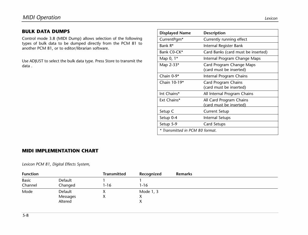
5-8
MIDI Operation Lexicon
BULK DATA DUMPSControl mode 3.8 (MIDI Dump) allows selection of the followingtypes of bulk data to be dumped directly from the PCM 81 toanother PCM 81, or to editor/librarian software.
Use ADJUST to select the bulk data type. Press Store to transmit thedata .
Displayed Name Description
CurrentPgm* Currently running effect
Bank R* Internal Register Bank
Bank C0-CK* Card Banks (card must be inserted)
Map 0, 1* Internal Program Change Maps
Map 2-33* Card Program Change Maps(card must be inserted)
Chain 0-9* Internal Program Chains
Chain 10-19* Card Program Chains(card must be inserted)
Int Chains* All Internal Program Chains
Ext Chains* All Card Program Chains(card must be inserted)
Setup C Current Setup
Setup 0-4 Internal Setups
Setup 5-9 Card Setups
* Transmitted in PCM 80 format.
MIDI IMPLEMENTATION CHART
Lexicon PCM 81, Digital Effects System,
Function Transmitted Recognized Remarks
Basic Default 1 1Channel Changed 1-16 1-16
Mode Default X Mode 1, 3Messages X XAltered X
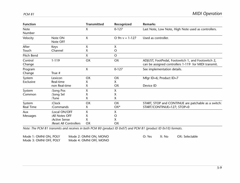
5-9
MIDI OperationPCM 81
Function Transmitted Recognized Remarks
Note X 0-127 Last Note, Low Note, High Note used as controllers.Number
Velocity Note ON X O 9n v = 1-127 Used as controller.Note OFF
After Keys X XTouch Channel X O
Pitch Bend X O
Control 1-119 OX OX ADJUST, FootPedal, Footswitch 1, and Footswitch 2, Change can be assigned controllers 1-119 for MIDI transmit.
Program X 0-127 See implementation details.Change True #
System Lexicon OX OX Mfgr ID=6; Product ID=7Exclusive Real-time X X
non Real-time X OX Device ID
System :Song Pos X XCommon :Song Sel X X
:Tune X X
System :Clock OX OX START, STOP and CONTINUE are patchable as a switch:Real Time :Commands X OX* START/CONTINUE=127; STOP=0
Aux :Local ON/OFF X XMessages :All Notes OFF X O
:Active Sense X X:Reset All Controllers OX OX
Note: The PCM 81 transmits and receives in both PCM 80 (product ID 0x07) and PCM 81 (product ID 0x10) formats.
Mode 1: OMNI ON, POLY Mode 2: OMNI ON, MONO O: Yes X: No OX: SelectableMode 3: OMNI OFF, POLY Mode 4: OMNI OFF, MONO
Troubleshooting
6Low Voltage ..................................................................................6-2
Overheating..................................................................................6-2
Common MIDI Problems ..............................................................6-2
Operational Problems ...................................................................6-3No Input • No Digital Audio Output • No Effects Output
Power On Behavior .......................................................................6-3
Restoring Factory Default Settings.................................................6-3
Reinitialization...............................................................................6-4
6-2
Troubleshooting Lexicon
This chapter is intended primarily to help you recognize somecommon error states which can be corrected from the PCM 81front panel, or by simple means such as cable replacement. Anyerror states which are not covered here should be referred to yourlocal dealer for service by a qualified technician.
LOW VOLTAGEIn a low-voltage, or "brown-out" condition, the PCM 81 will freezein its current state. None of the controls will have any effect. Whenpower returns to a normal level, the unit will reset itself as thoughit had just been powered on. If the unit does not reset itself, turnthe power OFF, then ON to resume normal operation.
OVERHEATINGTemperature extremes may cause the PCM 81 to exhibitunpredictable behavior. If the unit has been subjected totemperatures below 32°F (0°C) or above 95°F (35°C), it should beturned off and allowed to return to normal temperature before use.The unit may be damaged by exposure to temperatures below-22°F (-30°C) or above 167°F (75°C), or by exposure to humidityin excess of 95%. If a unit exposed to such conditions fails tooperate after it returns to a normal operating temperature, contactyour local service representative.
COMMON MIDI PROBLEMS
The PCM 81 doesn't respond to MIDI Program Changes.
Check Receive control at Control mode 3.1 and make sure it is setto On. Check the MIDI Channel selected as well as the MIDIChannel of the transmitting device. Make sure that Pgm Change atControl mode 3.3 is set to On. Also check MIDI In/Outconnections between the units.
MIDI Program Change numbers are off by 1.
The PCM 81 transmits and recognizes ProgramChange messages0-127. MIDI devices which transmit 1-128 rather than 0-127, willbe off by 1. Simply adjust by 1 when working with such devices.
The PCM 81 doesn't respond to SysEx commands.
Check the SysEx setting (and the Device ID selection) at Controlmode 3.7.
The PCM 81 does not transmit SysEx Automation commands.
Check the Automation setting (and the target device ID selection)at Control mode 3.4.
6-3
TroubleshootingPCM 81
OPERATIONAL PROBLEMS
The PCM 81 will not lock onto an incoming digital signal.
Check the cables that you are using. DO NOT USE ANALOG AUDIOCABLE TO CONNECT DIGITAL AUDIO.
Also check to make sure that your input signal complies withS/PDIF format standards. The PCM 81 will recognize AESprofessional format signals from an appropriate connector, but willnot necessarily read and transmit encoded information accurately.
NO INPUT
• Analog Check the analog input connection and makesure that the Analog Lvl control at Controlmode 0.1 is set to 100%.
• Digital AES Check connection to XLR and make sure thatAES (XLR): the Digital Lvl control at Control mode 0.2 is
set to 100%. Make sure that WordClock (Control mode 0.0) is set to Ext: XLR 48 or 44.1.
• Digital S/PDIF Check connection to Coax and make sure that(Coax): the Digital Lvl control at Control mode 0.2 is
set to 100%. Make sure that WordClock(Control mode 0.0) is set to Ext: XLR 48 or 44.1.
NO DIGITAL AUDIO OUTPUTCheck the Analog Lvl and Digital Lvl controls at Control mode 0.1and 0.2.
NO EFFECTS OUTPUTCheck the setting of Mix Mode at Control mode 1.1. Also verifythat any controllers patched to FX Lvl, Input Level, or Mix are notturned off.
POWER ON BEHAVIORThe PCM 81 performs a series of self tests each time it is poweredon, then displays the PCM 81 copyright notice. This should befollowed by the display and loading of the last loaded effect. If thissequence does not occur, contact Lexicon Customer Service.
RESTORING FACTORY DEFAULT SETTINGSYou can restore the PCM 81 to its default state without erasingregisters by restoring the factory default setup:
1. Press Control.
2. Use the Up and Down buttons to locate Row 4 Setup.
3. Turn SELECT to 4.1 Load.
4. Turn ADJUST counterclockwise to select "Factory Settings".
5. Press Load/. The PCM 81 will display the message "Setuprestored".
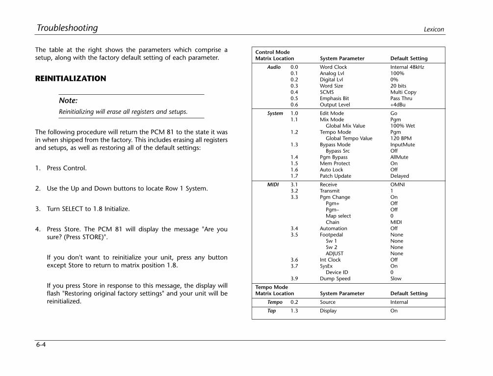
6-4
Troubleshooting Lexicon
The table at the right shows the parameters which comprise asetup, along with the factory default setting of each parameter.
REINITIALIZATION
Note:Reinitializing will erase all registers and setups.
The following procedure will return the PCM 81 to the state it wasin when shipped from the factory. This includes erasing all registersand setups, as well as restoring all of the default settings:
1. Press Control.
2. Use the Up and Down buttons to locate Row 1 System.
3. Turn SELECT to 1.8 Initialize.
4. Press Store. The PCM 81 will display the message "Are yousure? (Press STORE)".
If you don't want to reinitialize your unit, press any buttonexcept Store to return to matrix position 1.8.
If you press Store in response to this message, the display willflash "Restoring original factory settings" and your unit will bereinitialized.
Control ModeMatrix Location System Parameter Default Setting
Audio 0.0 Word Clock Internal 48kHz0.1 Analog Lvl 100%0.2 Digital Lvl 0%0.3 Word Size 20 bits0.4 SCMS Multi Copy0.5 Emphasis Bit Pass Thru0.6 Output Level +4dBu
System 1.0 Edit Mode Go1.1 Mix Mode Pgm
Global Mix Value 100% Wet1.2 Tempo Mode Pgm
Global Tempo Value 120 BPM1.3 Bypass Mode InputMute
Bypass Src Off1.4 Pgm Bypass AllMute1.5 Mem Protect On1.6 Auto Lock Off1.7 Patch Update Delayed
MIDI 3.1 Receive OMNI3.2 Transmit 13.3 Pgm Change On
Pgm+ OffPgm– OffMap select 0Chain MIDI
3.4 Automation Off3.5 Footpedal None
Sw 1 NoneSw 2 NoneADJUST None
3.6 Int Clock Off3.7 SysEx On
Device ID 03.9 Dump Speed Slow
Tempo ModeMatrix Location System Parameter Default Setting
Tempo 0.2 Source Internal
Tap 1.3 Display On

Appendix
ASpecifications ................................................................................A-2
Declaration of Conformity ............................................................A-4

A-2
Appendix Lexicon
Audio Input
Connectors: Combined 3 pole XLRand 1/4 inch T/R/Sphone jacks (2)
Impedance: 0 dB/BAL switch position:100kΩ, balanced
-20 dB/UNBAL switchposition: 50kΩ,unbalanced
Levels: 0 dB/BAL switch position:-2 dBu min for full scale,+20 dBu max
-20 dB/UNBAL switchposition: -22 dBu min forfull scale, 0 dBu max
CMRR: 0 dB/BAL switch position:50 dB minimum, 10 Hzto 20 kHz
Audio Output
Connectors: 1/4 inch T/R/S phonejacks (2); balanced XLRs,pin 2 "high" (2)
Impedance: 100Ω, balanced
Levels: +18dBm, full scale(+4dBu setting)balanced, unbalanced
+4dBm, full scale(-10dBu setting)
Audio Output (continued)
Protection: Relays provided foroutput muting duringpower on/off
A/D Performance
Frequency 10Hz to 20kHz, ±0.5dBResponse:
Crosstalk: <-65dB, 10Hz to 20kHz
S/N Ratio: >102dB, 20kHzbandwidth
THD: <0.003%, 10Hz to 20kHz
Dynamic >102dB, 20kHzRange: bandwidth
Delay: 24 samples (0.54ms for44.1kHz, 0.50ms for48kHz)
D/A Performance
Frequency 10Hz to 20kHz, ±0.5dBResponse:
Crosstalk: <-80dB, 10Hz to 20kHz
S/N Ratio: >98dB, 20kHzbandwidth
THD: <0.005%, 10Hz to 20kHz
Dynamic >98dB, 20kHzRange: bandwidth
D/A Performance (continued)
Delay: 50 samples (1.13ms for44.1kHz, 1.04ms for48kHz)
A/A Performance
Frequency 10Hz to 20kHz, ±0.5dBResponse:
Crosstalk: <-55dB, 10Hz to 20kHz
S/N Ratio: >96dB, 20kHzbandwidth
THD: <0.005%, 10Hz to 20kHz
Dynamic >96dB, 20kHzRange: bandwidth
Digital Audio Interface
Connectors: Coaxial, RCA type (2);Balanced, XLR (2)
Format: S/PDIF (IEC-958)consumer and AES/EBU(AES3-1992) professionalinterface
Sample Rates: 44.1kHz, 48kHz
Internal Audio Data Paths
Conversion: 24 bits
DSP: 20 to 24 bits
SPECIFICATIONS
A-3
AppendixPCM 81
External Memory Card
Connector: Accepts PCMCIA Type Icards, 68 pins
Standards: Conforms to PCMCIA2.0 / JEIDA 4.0
Card Format: Supports up to 1MBSRAM (attribute memorynot required)
Control Interface
MIDI: 5-pin DIN connectorsprovided for MIDI IN,THRU, and OUT
Footswitch: 1/4 inch T/R/S phonejack provided for 2independent momentaryfootswitches
System detects normal-open, or normal-closedon power up
Foot Controller: 1/4 inch T/R/S phonejack provided forfootpedal (100Ωminimum, 10kΩmaximum impedance)
General
Dimensions:
Width: 19.0 inches (483mm)
Height: 1.75 inches (45mm)
Depth: 12.0 inches (305mm)
19 inch rack mountstandard, 1U high
Weight:
Net: 6.4 lbs (2.9 kg)
Shipping: 9.5 lbs (4.3 kg)
Power 100-240 VAC, 50-60Hz,Requirements: 35 W, 3-pin IEC power
connector
RFI/ESD: Conforms to FCC Class B,EN55022 Class B (CE),IEC 801-2, IEC 801-3
Environment:
Operating 32 to 104˚F Temperature: (0 to 40˚C)
Storage -22 to 167˚FTemperature: (-30 to 70˚C)
Humidity: Maximum 95% withoutcondensation
Note:Unless otherwise noted, all audiospecifications assume rear-panelswitch set to BAL, input levelcontrol is set for unity gain (0dB),and analog I/O connections wiredfor balanced configuration.
Specifications subject tochange without notice.
DECLARATION OF CONFORMITY
Application of Council Directive(s):
73/23/EEC and 89/336/EEC
Standard(s) to which Conformity is Declared:
EN 50081-1:1992, EN 50082-1: 1992, and EN 55022:1994
Manufacturer:
Lexicon, Inc., 3 Oak Park, Bedford, MA 01730-1441 USA
The equipment identified here conforms to the Directive(s)and Standard(s) specified above.
Type of Equipment:
Digital Audio Effects Processor
Model:
Lexicon PCM 81
Date:
October 23, 1997
Lexicon, Inc.Vice President of Engineering3 Oak ParkBedford, MA 01730-1441 USATel: 781-280-0300Fax: 781-280-0490
A-4
Appendix Lexicon
Importers:
AUDIO SALESNeusiedlerstrasse 19Molding A-2340, Austria
TRANSEUROPEAN MUSICPontbleeklaan 411731 Zellik, Belgium
NEW MUSIKTeatergardenVestergrade 48 k8000 Arhus C, Denmark
STIRLING/ITAKimberly RoadLondon NW6 7SF, England
STUDIOTEC KYKuusiniewi 2Espoo SF-02710, Finland
BEYERDYNAMIC FRANCE7 rue Labie75017 Paris, France
AUDIO EXPORT/NEUMANN & CO.Badstrasse 147100 Heilbronn/Neckar,Germany
BON STUDIO LTD.8 Zaimi St/Exarchia106.83 Athens, Greece
GRISBY MUSIC PROFESSIONALS. S. Adriatica KM 309530Localita Aspio Terme60028 Osimo (Ancona), Italy
TM AUDIOZomerweg 14Ijsselstein, Holland BV 3402
CAIUS-TECNOLOGIAS AUDIOMUSICARua Sta Catarina 1314000 Porto, Portugal
TELCO ELECTRONICS S.A.Gravina 2728004 Madrid, Spain
SENNHEISER ABP. O. Box 22035Stockholm 10422, Sweden

LIMITED WARRANTY
Lexicon, Inc. offers the following warranty on this product:
What is the Duration of this Warranty?This warranty will remain in effect for one (1) year from the original dateof purchase.
Who is Covered?This warranty may be enforced by the original purchaser andsubsequent owners during the warranty period, provided the originaldated sales receipt or other proof of warranty coverage is presented at timeof service.
What is Covered?This warranty covers all defects in material and workmanship on thisproduct, except as specified below. The following are not covered:1. Damage resulting from
A. Accident, misuse, abuse, or neglect.B. Failure to follow instructions contained in the User Guide.C. Repair or attempted repair unauthorized by Lexicon, Inc.D. Failure to perform recommended periodic maintenance.E. Causes other than product defects, including lack of skill,
competence, or experience on the part of the owner.2. Damage occurring during any shipment of this product. Claims for
shipping damages must be made with the carrier.3. Damage to a unit that has been altered, or on which the serial
number has been defaced, modified, or removed.
What Expenses will Lexicon, Inc. Assume?Lexicon, Inc. will pay all labor and material expenses for covered items.Payment of shipping charges is discussed in the next section of thewarranty.
How is Service Obtained?When this product needs service, write, telephone, or fax Lexicon, Inc. torequest information about where the unit should be taken or sent. Whenmaking a written request, please include your name, complete address,and daytime telephone number; the product model and serial numbers;
and a description of the problem. Do not return the unit to Lexicon, Inc.without prior authorization.
When Shipping a Product for Service . . .1. Pay any initial shipping charges, which are the responsibility of the
owner. If necessary repairs are covered by this warranty, Lexicon, Inc.will pay return shipping charges to any destination in the United Statesusing the carrier of our choice.
2. Pack the unit securely. Package insurance is strongly recommended.3. Include a copy of the original dated sales receipt. (A copy of the
original dated sales receipt must be presented whenever warrantyservice is required.)
4. Do not include accessories such as power cords or user guides unlessinstructed to do so.
What are the Limitations of Implied Warranties?Any implied warranties, including warranties of merchantability andfitness for a particular purpose, are limited in duration to the length of thiswarranty.
What Certain Damages are Excluded?Lexicon’s liability for a defective product is limited to repair orreplacement of that product, at our option. Lexicon, Inc. shall not be liablefor damages based on inconvenience; loss of use of the product; loss oftime; interrupted operation; commercial loss; or any other damages,whether incidental, consequential, or otherwise.
How do State Laws Relate to this Warranty?Some states do not allow limitations on the duration of impliedwarranties and/or the exclusion or limitation of incidental orconsequential damages. As such, the above limitations may not apply.
This warranty is not enforceable outside of North America. Thiswarranty provides specific legal rights. Additional rights may be provided by some states.
A Harman International Company
Lexicon, Inc.3 Oak ParkBedford, MA 01730-1441USA
Tel 781-280-0300Fax 781-280-0490
www.lexicon.com
Customer SupportTel 781-280-0300Fax 781-280-0495 (Sales)Fax 781-280-0499 (Service)

A Harman International Company
Lexicon, Inc.3 Oak ParkBedford, MA 01730-1441 USATel 781-280-0300Fax 781-280-0490www.lexicon.com
Customer SupportTel 781-280-0300Fax 781-280-0495 (Sales)Fax 781-280-0499 (Service)
Lexicon Part No. 070-12614 | Rev 2 | 09/01
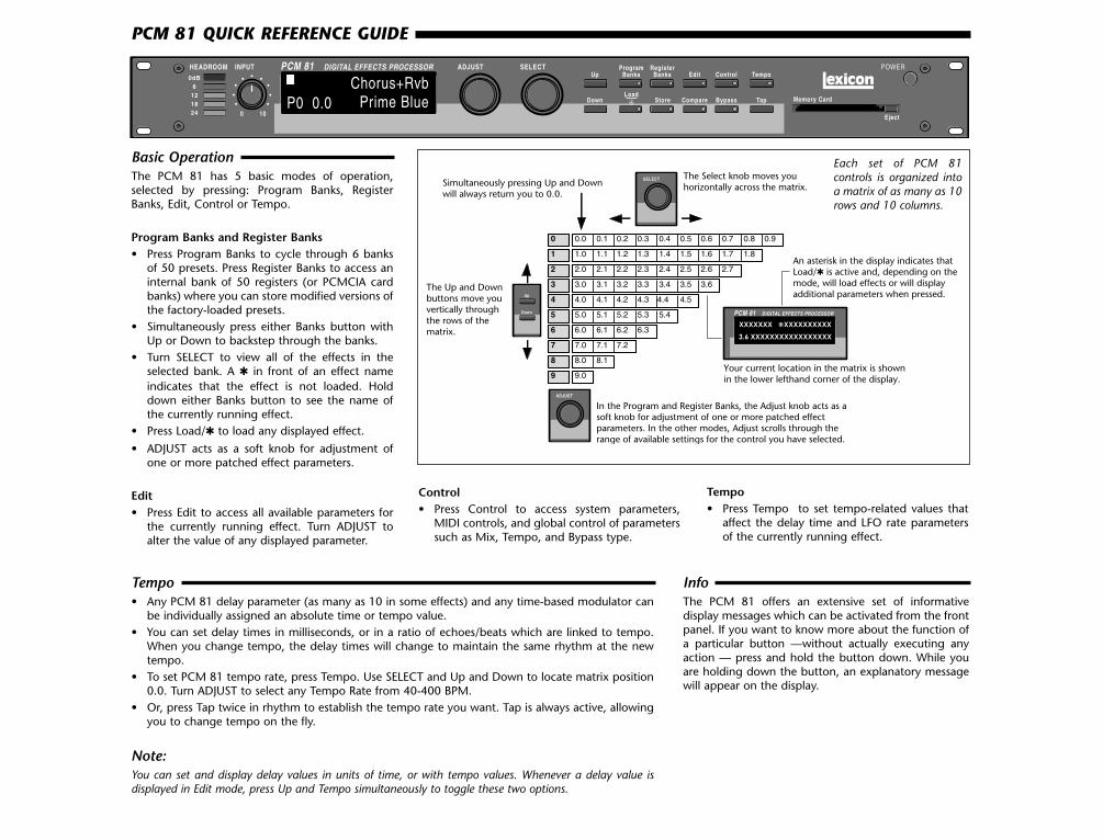
Basic OperationThe PCM 81 has 5 basic modes of operation,selected by pressing: Program Banks, RegisterBanks, Edit, Control or Tempo.
Program Banks and Register Banks• Press Program Banks to cycle through 6 banks
of 50 presets. Press Register Banks to access aninternal bank of 50 registers (or PCMCIA cardbanks) where you can store modified versions ofthe factory-loaded presets.
• Simultaneously press either Banks button withUp or Down to backstep through the banks.
• Turn SELECT to view all of the effects in theselected bank. A in front of an effect nameindicates that the effect is not loaded. Holddown either Banks button to see the name ofthe currently running effect.
• Press Load/ to load any displayed effect.
• ADJUST acts as a soft knob for adjustment ofone or more patched effect parameters.
Edit• Press Edit to access all available parameters for
the currently running effect. Turn ADJUST toalter the value of any displayed parameter.
HEADROOM DIGITAL EFFECTS PROCESSOR ADJUSTPCM 810dB
6121824 0 10
INPUT SELECT POWERUp
ProgramBanks
RegisterBanks Edit Control Tempo
DownLoad
Compare Bypass Tap Store Memory Card
Eject
Chorus+RvbPrime BlueP0 0.0
0 0.0 0.1 0.2 0.3 0.4 0.5 0.6 0.7 0.8 0.9
1 1.0 1.1 1.2 1.3 1.4 1.5 1.6 1.7 1.8
2 2.0 2.1 2.2 2.3 2.4 2.5 2.6 2.7
3 3.0 3.1 3.2 3.3 3.4 3.5 3.6
4 4.0 4.1 4.2 4.3 4.4 4.5
5 5.0 5.1 5.2 5.3 5.4
6 6.0 6.1 6.2 6.3
7 7.0 7.1 7.2
8 8.0 8.1
9 9.0
SELECT
Up
Down
ADJUST
DIGITAL EFFECTS PROCESSORPCM 81
XXXXXXX XXXXXXXXXX
3.6 XXXXXXXXXXXXXXXXX
The Select knob moves youhorizontally across the matrix.
The Up and Downbuttons move youvertically throughthe rows of thematrix.
In the Program and Register Banks, the Adjust knob acts as asoft knob for adjustment of one or more patched effectparameters. In the other modes, Adjust scrolls through the range of available settings for the control you have selected.
An asterisk in the display indicates thatLoad/ is active and, depending on themode, will load effects or will displayadditional parameters when pressed.
Your current location in the matrix is shownin the lower lefthand corner of the display.
Simultaneously pressing Up and Down will always return you to 0.0.
Each set of PCM 81controls is organized intoa matrix of as many as 10rows and 10 columns.
InfoThe PCM 81 offers an extensive set of informativedisplay messages which can be activated from the frontpanel. If you want to know more about the function ofa particular button —without actually executing anyaction — press and hold the button down. While youare holding down the button, an explanatory messagewill appear on the display.
Control• Press Control to access system parameters,
MIDI controls, and global control of parameterssuch as Mix, Tempo, and Bypass type.
Tempo• Press Tempo to set tempo-related values that
affect the delay time and LFO rate parametersof the currently running effect.
Tempo• Any PCM 81 delay parameter (as many as 10 in some effects) and any time-based modulator can
be individually assigned an absolute time or tempo value. • You can set delay times in milliseconds, or in a ratio of echoes/beats which are linked to tempo.
When you change tempo, the delay times will change to maintain the same rhythm at the newtempo.
• To set PCM 81 tempo rate, press Tempo. Use SELECT and Up and Down to locate matrix position0.0. Turn ADJUST to select any Tempo Rate from 40-400 BPM.
• Or, press Tap twice in rhythm to establish the tempo rate you want. Tap is always active, allowingyou to change tempo on the fly.
Note:You can set and display delay values in units of time, or with tempo values. Whenever a delay value isdisplayed in Edit mode, press Up and Tempo simultaneously to toggle these two options.
PCM 81 QUICK REFERENCE GUIDE

Compare• When you turn ADJUST, or perform any other parameter edits, the front panel
Compare light will go on to indicate that the program has been modified sinceit was last stored. Press Compare to hear the unedited version. Press again toreturn to your edited program.
Bypass• Press Bypass to mute the input signal. A Bypass Mode parameter at Control
mode 1.3 allows you to select input muting, output muting, input and outputmuting, or bypass as alternatives. You can also assign the bypass function to anexternal controller.
Audition the Programs• Press Program Banks to cycle through six banks of 50 presets.• Turn SELECT to view all of the presets in the selected bank.• Press Load/ to load any displayed effect.
• Each preset has one or more parameters patched to the ADJUST knob.• Turn ADJUST to display the name and the current value of the patch.• Continue turning ADJUST to change the value of the patch along its
entire range. The screen will return to its normal display when you stopturning ADJUST.
EditThe PCM 81 offers two levels of editing control: Go mode and Pro mode.
Go Mode• Go mode gives you access to a specific set of as many as 10
parameters for each of the 300 presets. We have designed each set ofparameters to allow you to make changes to the effect without losingthe character of the sound.
• In Go mode, press Edit to access the most useful preset parameters forthe currently running effect.
• Turn SELECT to view the available parameters.• Turn ADJUST to change the value of any displayed parameter.
Pro Mode• Pro mode gives you access to the full effect edit matrix whenever you
press Edit. The edit matrix contains all effect parameters, as well asPatching and Modulation controls.
• The PCM 81 is shipped in Go mode. To change the Edit mode, pressControl, use SELECT and Up and Down to locate matrix position 1.0.Turn ADJUST to select Go or Pro.
A Harman International Company
Lexicon, Inc.3 Oak ParkBedford, MA 01730-1441USA
Tel 781-280-0300Fax 781-280-0490
www.lexicon.com
Customer SupportTel 781-280-0300Fax 781-280-0495 (Sales)Fax 781-280-0499 (Service)
Bank P0• Multi Effects• Modulation Effects• Special Effects
Bank P1• Rhythmic Echo &
Delay Effects• Ambience Effects
Bank P2• EQ Effects• Spatial Effects• Gain Effects• Resonant Chord
Effects
Bank P3• Reverb Effects• Processed Reverb
Effects• Remix Effects
Bank P4• Vocal Shift• Vocal Harmony• Guitar Magic• Instrument Shift &
Harmony• Percussion & Tempo
Bank P5• Sci-Fi FX• Pitch & Delay• Pitch Sequences• Pads & Drones• Utility Programs• Pitch Correct
Store• Press Store. The current program name will appear with a flashing
cursor over the first letter of the name.• Turn ADJUST to select a new character. Press Up or Down to select a new
type of character (upper or lower case, numeric, symbolic, or blank). TurnSELECT to move the cursor to a new character.
• Press Load/ to display the name currently assigned to the ADJUST knobpatch. Use the same procedure for entering a new name.
• Press Load/ twice to move the to the Register ID number in the lowerleft corner of the display. Use ADJUST or SELECT to choose the registerwhere you want the effect saved.
• When the display shows the register number you want, press Store. PressStore in response to the "Are you sure?" message to save your new effectto the displayed register location.
Note:The PCM 81 will not perform a store instruction if the Memory Protection option ison. To turn Memory Protection off, press Control. Use Up and Down and SELECTto locate matrix position 1.5. Turn ADJUST to display Off.
In addition to these easy plug and play techniques, the PCM 81 providesextensive system control via front panel patching or MIDI. For completedetails on these and other features, read the PCM 81 Owner's Manual.


![CHA[LLE]NGE Ausgabe 1](https://img.dokumen.tips/doc/110x75/568bda101a28ab2034a961e5/challenge-ausgabe-1.jpg)