Embed Size (px)
Citation preview
PAVEMENT MANAGEMENT MANUAL
State of VermontAgency of Transportation
Vermont Agency of
Transportation
Pavement
Managem
ent Manual
Pavement Management Manual1998
State of VermontAgency of Transportation
Pavement Management iii
Table of Contents
Chapter One Organization and Administration
1.1 Mission and Scope of Responsibility ..........................................................................................................1-11.1.1 Mission ..............................................................................................................................................1-11.1.2 Scope of Responsibility .....................................................................................................................1-1
1.2 Organization ................................................................................................................................................1-1
1.3 Responsibility .............................................................................................................................................1-11.3.1 Program Development .......................................................................................................................1-21.3.2 Project Design ...................................................................................................................................1-21.3.3 Management and Administration ......................................................................................................1-2
1.4 Goals ...........................................................................................................................................................1-21.4.1 Section Goals .....................................................................................................................................1-21.4.2 Unit Goals ..........................................................................................................................................1-3
1.5 Human Resources .......................................................................................................................................1-3
1.6 Funding .......................................................................................................................................................1-41.6.1 Funding Sources ................................................................................................................................1-41.6.2 Funding Procedure ............................................................................................................................1-4
1.6.2.1 Long-Range Projections ..........................................................................................................1-41.6.2.2 Appropriations Process ............................................................................................................1-41.6.2.3 Funds Management ..................................................................................................................1-5
1.7 Support Activities........................................................................................................................................1-51.7.1 Project Definition Team .....................................................................................................................1-51.7.2 Pavement Design Committee ............................................................................................................1-51.7.3 Maintenance ......................................................................................................................................1-61.7.4 Planning .............................................................................................................................................1-6
iv Table of Contents
1.7.5 Roadway Design ................................................................................................................................1-61.7.6 Construction ......................................................................................................................................1-61.7.7 Materials and Research .....................................................................................................................1-61.7.8 Traffic Operations ..............................................................................................................................1-61.7.9 Specifications Committee ..................................................................................................................1-6
1.8 Public Information ......................................................................................................................................1-6
Chapter TwoNetwork Management
2.1 General ........................................................................................................................................................2-12.1.1 Network Goals ..................................................................................................................................2-12.1.2 Level of Improvement .......................................................................................................................2-12.1.3 Shoulder Paving ...............................................................................................................................2-22.1.4 Highway Safety .................................................................................................................................2-22.1.5 Preventive Maintenance ....................................................................................................................2-2
2.2 Network Condition ......................................................................................................................................2-32.2.1 Construction Quality .........................................................................................................................2-32.2.2 Research ............................................................................................................................................2-3
2.3 Location Referencing ..................................................................................................................................2-4
2.4 Network Analysis ........................................................................................................................................2-42.4.1 Computer Software ............................................................................................................................2-42.4.2 Database ............................................................................................................................................2-5
2.4.2.1 Content ....................................................................................................................................2-52.4.2.2 Updating ...................................................................................................................................2-62.4.2.3 Network Analysis .....................................................................................................................2-6
2.5 Trend Analysis ............................................................................................................................................2-7
2.6 Mapping ......................................................................................................................................................2-7
2.7 Annual Report .............................................................................................................................................2-7
Chapter Three Program Development
3.1 General ........................................................................................................................................................3-1
3.2 Program Development ................................................................................................................................3-13.2.1 General ..............................................................................................................................................3-13.2.2 Program Development Goals ............................................................................................................3-2
Pavement Management v
Vermont Agency of Transportation
3.2.3 Program Development Process .........................................................................................................3-33.2.4 Information Gathering .......................................................................................................................3-3
3.2.4.1 LOI Guidelines ........................................................................................................................3-33.2.4.2 Pavement Conditions ...............................................................................................................3-7
3.2.4.2.1 Field Surveys ..................................................................................................................3-73.2.4.2.2 Condition Survey Practice ..............................................................................................3-73.2.4.2.3 Supplementary Condition Assessment Activities ...........................................................3-83.2.4.2.4 Supplementary Information ............................................................................................3-83.2.4.2.5 Committed Work ............................................................................................................3-8
3.2.4.3 Budget ......................................................................................................................................3-93.2.4.4 Physical Constraints .................................................................................................................3-93.2.4.5 Performance Indexes ................................................................................................................3-9
3.3 Network Analysis ........................................................................................................................................3-93.3.1 General ..............................................................................................................................................3-93.3.2 Analysis Sections .............................................................................................................................3-103.3.3 Analysis Sets ....................................................................................................................................3-103.3.4 Generating Strategies ...................................................................................................................... 3-113.3.5 Performing Optimization ................................................................................................................. 3-11
3.4 Program of Projects ................................................................................................................................... 3-113.4.1 General ............................................................................................................................................ 3-113.4.2 Conceptual Project List ...................................................................................................................3-123.4.3 Field Review and Verification .........................................................................................................3-123.4.4 Project Cost Estimate ......................................................................................................................3-13
3.5 Comments and Suggestions ......................................................................................................................3-133.5.1 Management Comments ..................................................................................................................3-133.5.2 Other Comments ..............................................................................................................................3-13
3.5.2.1 Other Program Managers .......................................................................................................3-133.5.2.2 Maintenance Districts ............................................................................................................3-133.5.2.3 RPC/MPO ..............................................................................................................................3-143.5.2.4 Local Government .................................................................................................................3-14
3.5.3 Consideration of Comments ............................................................................................................3-143.6 Intermediate Program List ........................................................................................................................3-14
3.6.1 General ............................................................................................................................................3-143.6.2 Investigation and Study ...................................................................................................................3-143.6.3 Treatment Selection .........................................................................................................................3-16
3.7 Final Project List .......................................................................................................................................3-173.8 Program Approval ..............................................................................................................................3-173.9 Project Data for Design ......................................................................................................................3-18
3.9.1 General ......................................................................................................................................3-183.9.2 Required Data ...........................................................................................................................3-18
vi Table of Contents
Chapter FourProject Definition
4.1 Design Guidelines .......................................................................................................................................4-14.1.1 Design Standards ...............................................................................................................................4-14.1.2 Design Guidelines .............................................................................................................................4-14.1.3 Design Exceptions .............................................................................................................................4-2
4.2 Design Data .................................................................................................................................................4-2
4.3 Scope Definition ..........................................................................................................................................4-34.3.1 Surfacing ...........................................................................................................................................4-34.3.2 Shoulders ...........................................................................................................................................4-34.3.3 Safety Elements .................................................................................................................................4-3
4.3.3.1 Guardrail ..................................................................................................................................4-34.3.3.2 Signs .........................................................................................................................................4-44.3.3.3 Signals ......................................................................................................................................4-44.3.3.4 Roadside Obstacles ..................................................................................................................4-44.3.3.5 Intersections .............................................................................................................................4-4
4.3.4 Parking Provisions .............................................................................................................................4-44.3.5 HALs .................................................................................................................................................4-44.3.6 Pavement Marking ............................................................................................................................4-44.3.7 Drainage ............................................................................................................................................4-54.3.8 Bridges ...............................................................................................................................................4-54.3.9 Scenic Quality ...................................................................................................................................4-54.3.10 Americans with Disabilities Act (ADA) ..........................................................................................4-54.3.11 Railroad Crossings ...........................................................................................................................4-54.3.12 Sewer, Water, and Telephone ...........................................................................................................4-54.3.13 Design Exceptions ...........................................................................................................................4-5
4.4 Environmental Permitting ..........................................................................................................................4-6
4.5 Scenic Considerations .................................................................................................................................4-6
4.6 Finance and Maintenance Agreements .......................................................................................................4-6
4.7 Railroad Agreements ...................................................................................................................................4-6
4.8 Utility Agreements ......................................................................................................................................4-7
4.9 Coordination Requirements ........................................................................................................................4-8
4.10 Predesign Meetings ...................................................................................................................................4-8

Pavement Management vii
Vermont Agency of Transportation
Chapter FiveProject Plan Development
5.1 Consultant Contracting ...............................................................................................................................5-15.1.1 Scope of Work ...................................................................................................................................5-15.1.2 Selection ............................................................................................................................................5-15.1.3 Administration ...................................................................................................................................5-2
5.2 Preparation of Plans ....................................................................................................................................5-25.2.1 Information Sources ..........................................................................................................................5-25.2.2 Plan Set Makeup ................................................................................................................................5-2
5.2.2.1 General .....................................................................................................................................5-25.2.2.2. Title Sheet ...............................................................................................................................5-3
5.2.2.2.1. General ..........................................................................................................................5-35.2.2.2.2. Project Location Sketches .............................................................................................5-35.2.2.2.3. Project Area Map ...........................................................................................................5-35.2.2.2.4. Project Location and Description ..................................................................................5-45.2.2.2.5 Traffic Data .....................................................................................................................5-55.2.2.2.6 Conventional Symbols ...................................................................................................5-55.2.2.2.7 Control Data Block .........................................................................................................5-55.2.2.2.8 Notes ...............................................................................................................................5-55.2.2.2.9 Signatures .......................................................................................................................5-6
5.2.2.3 Index of Sheets .........................................................................................................................5-65.2.2.3.1 Contract Plans ................................................................................................................5-65.2.2.3.2 Standard Sheets ..............................................................................................................5-7
5.2.2.4 Typical Section Sheet ...............................................................................................................5-75.2.2.5 Quantity Sheets ........................................................................................................................5-85.2.2.6 Item Detail and Drainage Sheet ...............................................................................................5-95.2.2.7 Miscellaneous Roadway Details ..............................................................................................5-95.2.2.8 Layout Sheets .........................................................................................................................5-105.2.2.9 Utility Sheets .......................................................................................................................... 5-115.2.2.10 Traffic Control Sheets .......................................................................................................... 5-115.2.2.11 Signs and Lines Sheets ......................................................................................................... 5-115.2.2.12 Standard Sheets .................................................................................................................... 5-11
5.3 Development of Plans ............................................................................................................................... 5-115.3.1 Steps ................................................................................................................................................ 5-115.3.2 Review of Plans ............................................................................................................................... 5-11
5.4 Pay Items ...................................................................................................................................................5-12
5.5 Cost Estimates ...........................................................................................................................................5-125.5.1 Item Quantities ................................................................................................................................5-125.5.2 Unit Prices .......................................................................................................................................5-125.5.3 Estimate Format ..............................................................................................................................5-13
5.6 Right-of-Way Certificates .........................................................................................................................5-13
viii Table of Contents
5.7 Utility Agreements ....................................................................................................................................5-13
5.8 Categorical Exclusions ..............................................................................................................................5-13
5.9 Other Requirements ..................................................................................................................................5-145.9.1 Salvage ............................................................................................................................................5-145.9.2 Field Office ......................................................................................................................................5-145.9.3 Contract Duration or Completion Date ...........................................................................................5-145.9.4 Traffic Control .................................................................................................................................5-145.9.5 Employee Training ..........................................................................................................................5-14
5.10 Coordination Requirements ....................................................................................................................5-14
5.11 Contract Special Provisions ....................................................................................................................5-14
Chapter SixQuality Assurance
6.1 Introduction .................................................................................................................................................6-1
6.2 Section Efforts.............................................................................................................................................6-1
6.3 Program Quality ..........................................................................................................................................6-2
6.4 Design Quality ............................................................................................................................................6-3
6.5 Construction Quality ...................................................................................................................................6-3
6.6 Program Oversight ......................................................................................................................................6-4
Chapter SevenContract Plans
7.1 Introduction .................................................................................................................................................7-1
7.2 Composite Projects .....................................................................................................................................7-1
7.3 Composite Plan Set .....................................................................................................................................7-17.3.1 Composite Title Sheet .......................................................................................................................7-27.3.2 Composite Index of Sheets ................................................................................................................7-27.3.3 Composite Quantity Summary ..........................................................................................................7-2
7.4 Contract Estimate ........................................................................................................................................7-3
7.5 Required Documents ...................................................................................................................................7-3
7.6 Document Processing ..................................................................................................................................7-5
7.7 Transmittal ..................................................................................................................................................7-5
Pavement Management ix
Vermont Agency of Transportation
7.8 Contract Processing ....................................................................................................................................7-67.8.1 General ..............................................................................................................................................7-67.8.2 Special Provisions .............................................................................................................................7-77.8.3 Bid Package .......................................................................................................................................7-77.8.4 Advertising ........................................................................................................................................7-77.8.5 Bids ....................................................................................................................................................7-77.8.6 Bid Review ........................................................................................................................................7-8
Chapter EightConstruction
8.1 General ........................................................................................................................................................8-1
8.2 Role During Construction ...........................................................................................................................8-1
8.3 Construction Support ..................................................................................................................................8-18.3.1 Added Work .......................................................................................................................................8-28.3.2 Decision Making ..............................................................................................................................8-2
8.4 Construction Quality ...................................................................................................................................8-2
8.5 Feedback .....................................................................................................................................................8-3
8.6 Cross-Training ............................................................................................................................................8-3
Chapter NineMaintenance
9.1 General ........................................................................................................................................................9-1
9.2 Maintenance Indicators ...............................................................................................................................9-19.2.1 Potholes .............................................................................................................................................9-19.2.2 Edge Breakup ....................................................................................................................................9-29.2.3 Cracking ............................................................................................................................................9-29.2.4 Depressions .......................................................................................................................................9-29.2.5 Roughness .........................................................................................................................................9-29.2.6 Rutting ...............................................................................................................................................9-3
9.3 Maintenance Programs ................................................................................................................................9-39.3.1 Routine Maintenance .........................................................................................................................9-3
9.3.1.1 Potholes ....................................................................................................................................9-39.3.1.2 Leveling ...................................................................................................................................9-3
9.3.2 Preventive Maintenance ....................................................................................................................9-39.3.2.1 Project Selection ......................................................................................................................9-49.3.2.2 Crack-Filling and Sealing .......................................................................................................9-4
x Table of Contents
9.3.2.3 Special Problems ......................................................................................................................9-59.3.3 Crack Filling ......................................................................................................................................9-5
9.3.3.1 Crack Preparation ....................................................................................................................9-59.3.3.2 Filler Material ..........................................................................................................................9-69.3.3.3 Material Requirements and Cost ..............................................................................................9-69.3.3.4 Service Life ..............................................................................................................................9-69.3.3.5 Specifications ...........................................................................................................................9-7
9.3.4 Sealing ...............................................................................................................................................9-79.3.4.1 Seal Preparation .......................................................................................................................9-79.3.4.2 Seal Materials ..........................................................................................................................9-79.3.4.3 Specifications ...........................................................................................................................9-79.3.4.4 Service Life ..............................................................................................................................9-8
Appendix Appendix
Pavement Management xi
VERMONT AGENCY OF TRANSPORTATIONVERMONT AGENCY OF TRANSPORTATION
List of Figures
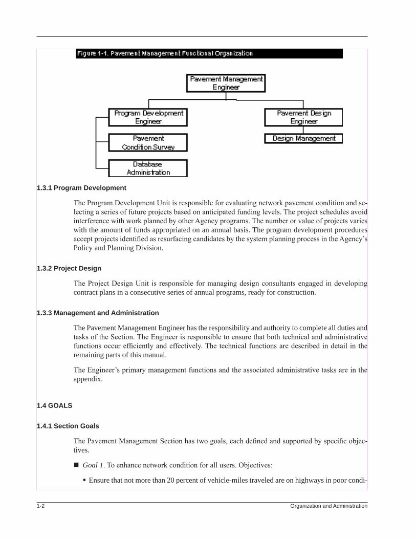
1-1 PavementManagementFunctionalOrganization...................................................................................1-2
3-1 ProgramDevelopmentTimeLine...........................................................................................................3-4
3-2 ProgramDevelopmentProcess...............................................................................................................3-5
3-3 LevelofImprovementTreatments..........................................................................................................3-6
3-4 SeverityStandardsforGradingCrackandPatchConditions.................................................................3-8
3-5 ExtentStandardsforGradingCrackandPatchConditions....................................................................3-8
3-6 SeverityStandardsforGradingRuttingandRoughness.........................................................................3-8
5-1 IndexList................................................................................................................................................5-6
5-2 StandardSheetCrossReferences............................................................................................................5-7
A-1 SectionAdministration...........................................................................................................................A-2
A-2 ScopeStatementforDesignRFP...........................................................................................................A-4
A-3 ScopeStatementforConditionSurveyRFP........................................................................................ A-11
A-4 ConsultantPaymentSpreadsheet.........................................................................................................A-15
A-5 InterimPolicyonResurfacing.............................................................................................................A-16
A-6 TestingandInvestigationSpreadsheet.................................................................................................A-20
A-7 TreatmentOptions................................................................................................................................A-21
A-8 AdvisoryLettertoTown......................................................................................................................A-24
A-9 FinalProjectList..................................................................................................................................A-25
A-10 FormPAR/DB......................................................................................................................................A-26
A-11 Class1FinanceandMaintenanceAgreement.....................................................................................A-29
A-12 DesignRecommendation.....................................................................................................................A-32
A-13 PavementManagementProjectInformationSpreadsheet...................................................................A-33
xii List of Figures
A-14 STPPavingProjects—DesignObjectives............................................................................................A-34
A-15 DraftPolicyonShoulderPaving..........................................................................................................A-36
A-16 GuidelinesforBridgesonSTPProjects...............................................................................................A-37
A-17 DesignExceptionRequest...................................................................................................................A-41
A-18 ListofScenicHighways......................................................................................................................A-47
A-19 Title23,V.S.A.,Section1104..............................................................................................................A-48
A-20 HALAnalysis.......................................................................................................................................A-49
A-21 RequestforCategoricalExclusion.......................................................................................................A-60
A-22 Title19,V.S.A.,Section306a..............................................................................................................A-70
A-23 RailroadAgreement.............................................................................................................................A-71
A-24 Utilities–LettersandSpecialProvisions—StateSystem......................................................................A-79
A-25 Utilities–LettersandSpecialProvisions—Class1TownHighways...................................................A-82
A-26 InvitationforProposal..........................................................................................................................A-85
A-27 NoticetoProceed.................................................................................................................................A-86
A-28 SpreadsheetforDesignWorkFlow.....................................................................................................A-87
A-29 PlanSheets...........................................................................................................................................A-89
A-30 StandardDrawingIndex....................................................................................................................A-104
A-31 TransmittalLetterforSubmissionofPlans........................................................................................A-109
A-32 TransmittalLetterforReceiptofPlans.............................................................................................. A-110
A-33 UnitPriceList—ExampleSheets....................................................................................................... A-111
A-34 ProjectCostEstimate......................................................................................................................... A-113
A-35Right-of-WayCertificate—StateHighway........................................................................................ A-115
A-36Right-of-WayCertificate—Class1TownHighway........................................................................... A-116
A-37 DispositionofSalvageableMaterial.................................................................................................. A-117
A-38 MemorandumfortheDisposalofSalvageableMaterial................................................................... A-119
A-39 FieldOfficeRequirementsForm........................................................................................................A-120
A-40 ConstructionDurationForm..............................................................................................................A-121
A-41 ConsultantEvaluationForm..............................................................................................................A-125
A-42 HighEstEstimate................................................................................................................................A-127
Pavement Management xiii
Vermont Agency of Transportation
A-43 PolicyonStandardizingCADDFiles................................................................................................A-132
A-44 CADDGuidelinesforPavingPlans...................................................................................................A-138
A-45 DesignComputations.........................................................................................................................A-146
A-46 SpecialProvisionRequirements........................................................................................................A-151
A-47 RailroadCrossingMemorandum.......................................................................................................A-154
A-48 RecommendationforCategoricalExclusion.....................................................................................A-155
A-49 TransmittalRequestforPrints............................................................................................................A-157
A-50 TRNSPORTEstimate.........................................................................................................................A-158
A-51 FinancingMemorandum....................................................................................................................A-164
A-52 FormCA-52,ConstructionProjectCostAllocation..........................................................................A-165
A-53 ProjectAdvertisingMemorandum.....................................................................................................A-166
A-54 BidAnalysisandRecommendation...................................................................................................A-167

xiv List of Figures
Pavement Management 1-1
Chapter OneOrganization and Administration
1.1 MissiOn And scOpe Of RespOnsibility
1.1.1 Mission
The mission of the Pavement Management Section is to preserve and improve the pavement condi-tion level, within the limits of funds available, on State highways, Interstate highways, and Class 1 town highways.
1.1.2 scope of Responsibility
The Section defines appropriate resurfacing work on the highways, both by contract and force ac-count, and manages the funds appropriated for paving. Its responsibilities include data collection and research, network analysis and project selection, and production of project construction plans.
1.2 ORgAnizAtiOn
The Pavement Management Section is a part of the Construction and Maintenance Division. The Section head is the Pavement Management Engineer, who is supported by a staff of engineers and technicians in two primary subsections, Program Development and Project Design. The Pavement Management Engineer reports directly to the Director of the Construction and Maintenance Divi-sion. The Section organization chart is shown in Figure 1-1.
1.3 RespOnsibility
The Pavement Management Section is responsible for the full range of program delivery tasks and, with a program financial management capability, it becomes a virtual stand-alone program-delivery unit. It has assistance from agency-level support services, including accounting, human resources, bid letting, and project construction inspection. The two functional units carry out the responsibili-ties of the Section.
1-� Organization and Administration
1.3.1 program development
The Program Development Unit is responsible for evaluating network pavement condition and se-lecting a series of future projects based on anticipated funding levels. The project schedules avoid interference with work planned by other Agency programs. The number or value of projects varies with the amount of funds appropriated on an annual basis. The program development procedures accept projects identified as resurfacing candidates by the system planning process in the Agency’s Policy and Planning Division.
1.3.2 project design
The Project Design Unit is responsible for managing design consultants engaged in developing contract plans in a consecutive series of annual programs, ready for construction.
1.3.3 Management and Administration
The Pavement Management Engineer has the responsibility and authority to complete all duties and tasks of the Section. The Engineer is responsible to ensure that both technical and administrative functions occur efficiently and effectively. The technical functions are described in detail in the remaining parts of this manual.
The Engineer’s primary management functions and the associated administrative tasks are in the appendix.
1.4 gOAls
1.4.1 section goals
The Pavement Management Section has two goals, each defined and supported by specific objec-tives.
Goal 1. To enhance network condition for all users. Objectives:
Ensure that not more than 20 percent of vehicle-miles traveled are on highways in poor condi-

Pavement Management 1-�
Vermont Agency of transportation
tion.
Incorporate appropriate safety standards in all paving projects.
Satisfy various user benefits and interests through balanced design objectives.
Ensure that all designs are consistent with Agency goals regarding multimodalism.
Acknowledge the current condition of the existing network.
Define and ensure full implementation and operation of the preventive maintenance pro-gram.
Goal 2. To manage the paving program effectively. Objectives:
Document and convey resource needs.
Ensure appropriate and effective use of all paving funds.
Ensure employees have ample opportunities to expand knowledge and skills.
Expand production capabilities through effective use of other AOT staff.
Ensure that all contract plan work is completed on time and comprehensively to accomplish program paving efficiently and effectively.
Ensure that data collection needs of other divisions are met.
The Section’s goals, objectives, and strategies were developed in a strategic planning effort and published in the strategic plan for the Construction and Maintenance Division in July 1994. The strategic planning effort is necessarily continuous because it must be responsive to changes in the Section’s environment. The Section’s goals, objectives, and strategies are modified periodically as indicated by the strategic planning process.
1.4.2 Unit goals
The Program Development Unit has the goal of developing lists of projects (programs) that are timely and well coordinated with all other Agency activities.
The Project Design Unit has the goal of developing contract plans and specifications that are timely to take advantage of all available funds.
1.5 HUMAn ResOURces
Due to limited staffing, the Pavement Management Section relies on consulting engineering firms to provide much of its essential labor and technical support. These firms provide the following services:
Condition inspection, including skid testing Project design, including environmental clearances Shop drawing review
Firms are employed on retainer contracts extending over a three- or four-year term. During the term
1-� Organization and Administration
the Section may call on the consultant to perform services as needed to support program develop-ment and project design.
The Program Development Engineer is responsible for consultant tasking and administering the condition inspection contracts. The Pavement Design Engineer is responsible for consultant tasking and administering the project design and shop-drawing review contracts.
The general procedures and responsibilities related to engaging consultants and administering their contracts are in the Agency publications Policy and Procedures for Consultant Selection and Con-tract Processing and Guidance for Procurement Contracts, Grants, and Cooperative Agreements. Typical scope statements for requests for proposals (RFP) for both design services and condition survey are in the appendix.
1.6 fUnding
1.6.1 funding sources
Funds managed by the Pavement Management Section are primarily federal funds augmented by the necessary State matching funds. Federal funding categories may be Interstate 4R Construction (IM), National Highway System (NHS), or State Transportation Program (STP). Matching requirements are ten percent for the IM funds and twenty percent for the other categories.
The Section attempts to make the best use of federal funds, which are exclusively for contracted work awarded through competitive bids. If State funds are available, the work is occasionally done with State forces on a force-account basis or through a grant to a municipality.
1.6.2 funding procedure
1.6.2.1 long-Range projections
Program funding guidance is published in the Agency’s Long-Range Plan. The Agency’s Budget Of-ficer and Programming Engineer are also good sources for long-range funding information. Funding is not firm for an annual program of projects until appropriation action by the General Assembly. However, the Capital Program and the State Transportation Improvement Program (STIP) provide some reliable guidance.
The Agency’s Capital Program and Project Development Plan, which is an annual report to the General Assembly, suggests annual funding levels for the major programs extending five years into the future. The STIP indicates specific projects on which federal funds are committed three years into the future. In the STIP, projects are listed according to the federal program category selected by the Agency’s Programming Engineer. Paving projects are listed individually, except that the preliminary engineering (PE) for the STP and NH projects are separate lump sums.
1.6.2.2 Appropriations process
The appropriated State funds are available on July 1 for the next fiscal year. The appropriation process for the next year begins shortly after the beginning of the current fiscal year, when the State Administration provides budget targets to the Agency’s Budget Officer. The Budget Officer provides the target for paving, usually in August of each year. Target amounts indicate both federal and State funds for use in the category of Other, with no split into Personal Services and Operating Expenses. The Agency makes a budget proposal to the General Assembly in early January. The ap-
Pavement Management 1-�
Vermont Agency of transportation
proved budget, which may be different from that proposed, is usually appropriated in the next April for the ensuing fiscal year.
Funds are appropriated in the Other category and may be expended for PS, OE, or construction contractor payments. The Personal Services (PS) category provides funds for state employee salaries and fringe benefits and also supports the costs for consultant work. The Operating Expense (OE) category includes such items as employee expenses, equipment rental and repair, and space rental.
1.6.2.3 funds Management
The Pavement Management Section is responsible for managing its appropriated funds. The Pave-ment Management Engineer continually monitors appropriation balances to confirm that the funds are being drawn down as anticipated. Any balance carryover into the next fiscal year is minimized by expending the funds through contracts or by scheduling force-account work.
Newly appropriated funds are added to previous year-end balances (carryover amounts) at the be-ginning of the State fiscal year on July 1. The effect of any appropriation transfers prescribed by the Budget Adjustment Act or the Appropriations Act is entered at the same time. Entries to start the accounting system at the beginning of the fiscal year are made by the Agency’s Budget Officer.
The Section tracks available funds with the Agency’s State Transportation Accounting Reporting System (STARS). Expenditures and balances are tracked at both the appropriation level and the project level with STARS. Refer to the STARS manual and to personnel in the Financial Manage-ment Section of the Administration Division for information on reports that are available and how they may be used to advantage.
The STARS data is the official accounting information for the Section, although some informal accounting within the unit is necessary for planning and management purposes. A summary of pay-ments to consultants for design services, summarized by consultant and project, is an example of useful management information. An example of this spreadsheet is in the appendix.
On occasion, the Pavement Management Engineer is required to make a projection of the year-end balance in the paving appropriation. This task requires careful attention to the status of payments in progress and the remaining payments anticipated under the contracts or for operations, relative to the current indicated balance in the appropriation. Information is secured from the Construction Section regarding project status and projected expenditures. A five-percent contract overrun factor is anticipated when making projections.
1.7 sUppORt ActiVities
The Pavement Management Section provides support to the following Agency units and activi-ties.
1.7.1 Project Definition Team
The Pavement Management Engineer serves as a member of the Project Definition Team (PDT). The PDT is made up of managers from the principal Agency units. Its primary role is to review project managers’ reports at the end of the project definition phase and any substantial changes in the scope and cost of capital projects, with the goal of assuring engineering excellence.
1-� Organization and Administration
1.7.2 pavement design committee
The Pavement Management Engineer serves as a member of the Agency’s Pavement Design Com-mittee. The Section supports the research activities of the Committee and advises on the Agency’s Pavement Design Guide and Pavement Rehabilitation Guide.
1.7.3 Maintenance
Pavement Management contracts work for crack sealing, thin overlays, seals, and other preventive maintenance activities.
1.7.4 planning
Pavement Management provides pavement condition information to the Agency’s GIS database and for the Highway Performance Monitoring System (HPMS) report to FHWA. The Section occasion-ally provides pavement depth and structural capacity information to assist system planning.
1.7.5 Roadway design
Pavement Management provides recommendations on the appropriate pavement thickness for rehabilitation projects. The Section also suggests possible treatment options to assist in project definition efforts.
1.7.6 construction
Pavement Management provides advice to resident engineers on paving projects regarding unexpected issues encountered during construction. Issues may include drainage problems, required modifica-tions of guardrail installation standards, changes of project scope, and interpretation of contract plan details. The Section may provide ride quality measurements.
1.7.7 Materials and Research
Pavement Management provides field data to support Materials and Research activities on the Pave-ment Life Study, the Strategic Highway Research Program (SHRP) site-monitoring activity, and the Agency Research Advisory Committee’s study of new or improved products and materials.
1.7.8 Traffic Operations
Pavement Management provides field data on the skid characteristics of pavement surfaces, at locations requested by the Highway Research Data and the Traffic Operations units, by tasking a consultant. Representative projects, with aggregates from the major suppliers, are skid tested when newly laid and after they are subjected to traffic, in an effort to identify polish-susceptible stone.
1.7.9 Specifications Committee
Pavement Management has a member on the Agency’s Specifications Committee. The Committee is made up of technical experts from the principal Agency functions. It passes on all changes to the Standard Specifications for Construction.
Pavement Management 1-�
Vermont Agency of transportation
1.8 pUblic infORMAtiOn
The annual Paving Program Report is a key element of the Section’s information efforts. This pub-lication is actively sought by legislators, industry representatives, and Agency management. The report is issued at the beginning of the calendar year and contains information on work completed and conditions existing at that time.
Another information effort is the description of the paving program contained in the Agency’s Capital Program and Project Development Plan. This document is the subject of interactive TV hearings and is also an annual report to the Legislature.
Communities are notified, and in some cases meetings are held with their managers, during the program formation phase.
The Section regularly provides information to the staff of the Regional Planning Commissions, who in turn inform the local governments.

1-� Organization and Administration
Pavement Management 2-�
Chapter TwoNetwork Management
2.1 GeNeral
The Pavement Management Section is responsible for maintaining the paved roadway surfaces on a statewide network, including the 3860-kilometer State highway system, 1030 kilometers of two-lane road and 115 kilometers of ramps on the Interstate system, and 225 kilometers of Class 1 town highway. Sophisticated equipment and techniques assess the health of the network and help develop systematic repairs and maintenance actions.
The Section has broad goals and program measures as guides for managing the network.
2.1.1 Network Goals
Program effectiveness in the Agency is monitored by consistent, observable performance measures. For the paving program, the measures are the overall network condition and the portion of the net-work in poor condition. See Section 3.2.4.5 for a discussion of condition indexes.
The goals for the paving program are:
Average condition of all vehicle-miles traveled is greater than 60 on a scale of 0 to 100 Less than 20 percent of the vehicle-miles traveled are on roadways in poor condition
An annual report of program effectiveness must accompany the paving program budget request.
2.1.2 level of Improvement
The Pavement Management Section adheres to the concept of the Agency’s Level of Improvement Policy (LOI). This guide recognizes that the funding available to the Agency is insufficient to fully address all needs. Conceptually, the surfaces of the more important highways are maintained to a higher quality than those of the lower category highways.
To implement this concept, the Section has established acceptable pavement quality standards that differ among the Interstate highways, the National Highway System (NHS) highways, and all other State highways. Thus, before resurfacing is considered, a low-volume collector roadway will have reached a lower ride quality than an Interstate will have reached. The resurfacing treatment provided to the low-volume collector will be a less expensive maintenance-like treatment than that provided
2-2 Network Management
to an Interstate.
All treatment options, except for chip seals, are available for the Interstate and the NHS. The high‑order treatments, such as recycling, reclaiming, structural overlays, and mill‑and‑fill, are sub-stantially higher in cost. They are not available for the lower classification roadways under the LOI guidelines. Refer to Figure 3-3, on Page 3-6.
Exceptions to the treatments available under the LOI may be approved by the Pavement Manage-ment Engineer on a case‑by‑case basis. For instance, mill‑and‑fill may be necessary on a curbed collector highway, and cold-recycled-and-overlay treatment may be appropriate on a well-built segment of rural arterial.
2.1.3 Shoulder Paving
It is a statutory requirement to provide paved shoulders for bicycling on major State highways. (See Title 19 Section 2310, Vermont Statutes Annotated, for the full text.) A paved shoulder also aids in providing a safe roadway. During resurfacing, pave the shoulders on major routes where feasible. Resurfacing of existing paved shoulders is done, if warranted, during resurfacing projects.
2.1.4 Highway Safety
The Agency’s “Interim Policy on Resurfacing,” filed with the FHWA, requires the Agency to pro-vide for improving safety in conjunction with federal-aid resurfacing projects. The policy pertains to highways other than those on the Interstate System. It provides for the following:
All locations with an accident actual-rate-to-critical-rate ratio of greater than 2.0 are examined. If feasible, within the existing rights-of-way, project designs will improve safety at those loca-tions.
Existing guardrail that is not of current standard may be replaced in its existing location. Install new guardrail at locations if no guardrail is present and if there is an obvious hazard, such as deep water, to a motorist who might go off the highway.
Existing throat-type drop inlets may be replaced with grated inlets.
Traffic signs and roadway markings may be upgraded to current standards.
A copy of the policy is in the appendix.
Projects on the Interstate highways are subject to more extensive safety improvement requirements. The policy on this topic is in the VAOT 3R Policy.
To vary from either policy requires a design exception.
2.1.5 Preventive Maintenance
It is desirable to intervene early in the life cycle and to slow the rate at which pavement deteriorates. The goal is to apply low-cost treatments to those pavements that have good subgrade support and adequate subbase, timely enough to defer more expensive treatments. Crack‑filling, thin overlays, chip seals, fog seals, slurry seals, and microsurfacing are appropriate preventive maintenance treat-ments.
Pavement Management 2-�
Vermont agency of Transportation
2.2 NeTwork CoNdITIoN
Accurate knowledge of the condition of the highway network is essential to allow informed decisions on practices and policies for the roadway surfaces. Condition assessment activity serves a number of purposes. The most obvious purpose is to track the system’s condition. Condition data also is the basis for selecting the location and the scope for work to be scheduled, supports research efforts, and aids in the development of construction specifications.
2.2.1 Construction Quality
The Construction Section’s efforts to develop an “end‑result” specification for ride quality on new construction and resurfacing is aided by measuring surface roughness. Roughness is measured on projects selected by Construction, both prior to and after placing each layer of pavement. Minimum acceptable values of roughness are established from the data. The intent is to have the construc-tion specifications contain acceptable roughness values for Interstate work and for State highway work.
This activity is part of the Agency’s QC/QA emphasis, toward the goal of improving the quality and effectiveness of Agency programs.
2.2.2 research
Ride quality surveys aid and supplement several Agency research efforts.
One of the efforts is the Materials and Research Section’s Pavement Life Study. The study moni-tors the performance of surface types at over 70 locations throughout the State. At these locations, condition data is periodically recorded on 30-meter roadway sections. Ride quality and falling weight deflectometer (FWD) values are measured on each test section. The intent of the study is to determine the life expectancy of various combinations of materials. The study also examines the relationship between the development of roughness and the equivalent single-axle loading (ESALs) actually experienced.
Another Materials and Research effort is to verify the effectiveness of crack‑filling on bituminous pavement. In this study, the cracks in one half of selected roadways are filled, while the other side is left untreated. Ride quality on both sides of the roadway is measured periodically.
The Pavement Design Committee’s research activity is supported with FWD readings on the subgrade and on each layer of subbase material to verify that expected layer coefficients are being attained. This activity applies to selected new construction projects each year.
A contractor measures the friction characteristics of selected roadway surfaces, under an ongoing Pavement Skid Resistance Study. Selecting the location for the surveys is done in conjunction with the Agency’s Traffic Operations unit. The contractor publishes a Skid Testing Report.
Calibration sites are prepared for the Section’s ride-quality equipment, as well as the contractor’s, by use of the “dipstick” (profilometer). The sites are approximately 300 meters long, at strategic locations throughout the State. The sites have varying degrees of roughness. Detailed information is determined on the ride quality in both wheel tracks. Sites are surveyed each year.

2-� Network Management
2.3 loCaTIoN refereNCING
The Pavement Management Section uses the route–town–mile-marker system as reference, except that freeway-type highways are measured from end to end of the routes. The route logs produced by the Agency’s Mapping Section are the basic documentation and reference. Project locations are defined with this system.
In the general location system, each route has a zero measurement at the town (boundary) line. Dis-tance along the route is measured along the centerline, proceeding south to north or west to east. At the next town line, the measurement is reset to zero.
Any change in route alignment obviously creates a shift in data reference for those roadway seg-ments located beyond the change. Confusion occurs if routes merge, becoming coincident on the same roadway, and then diverge.
To avoid reference problems and to allow adjustment of data locations, the reference locations of bridges, major highway intersections, and railroad crossings are included in the pavement manage-ment database. Because bridge locations are identified during roadway condition survey runs, they are available for location adjustments.
Freeway-type highways are referenced to base lines, off which markers are placed on the right shoulder of each lane, increasing south to north or west to east. These markers, which are at nominal one-mile (1.6-kilometer) intervals, are the location references. The locations of bridges on each lane are in the pavement management database and also provide location references.
2.4 NeTwork aNalySIS
Pavement Management employs sophisticated analysis techniques to select the appropriate treatment type and timing. Extensive computerized databases contain detailed records collected over several years. The Section uses specialized computer software to analyze the data.
A system administrator operates and manages the software system. The administrator is responsible for loading data, distributing data to others, modifying the models, preparing reports, etc.
The description of the software system in this manual is only an overview. For details on the system and its features, refer to the publication Development of VAOT’s PMS and its appendix, by Deighton Associates, July 1995.
2.4.1 Computer Software
The pavement management software was acquired in 1995 from Deighton Associates, Bowmanville, Ontario. It consists of three parts:
A relational database containing detailed information on surface condition, pavement type, high accident locations, etc., extending over several years. The software allows manipulation of the raw information so that it is suitable for analysis and reports. The software is referred to as “dROAD.”
An analysis segment that uses the relational database information on which to base a sophisticated analysis and project selection procedure. The program has considerable versatility stemming from its editable analysis parameters, performance curves, and indexes. The software is referred to as
Pavement Management 2-�
Vermont agency of Transportation
“dTIMS.”
A mapping segment that displays information from the dROAD segment. It provides the capability to query and edit the database by selecting a map location on the screen. The software is referred to as “dMAP.”
The following is a generalized description of the activities associated with and the functions of the software. The software manuals and training videos are available to provide detail.
2.4.2 database
2.4.2.1 Content
The pavement management database contains a great deal more information than surface condition data and its location references. The initial database had 24 perspectives, or views, of the highway system. Each perspective contains data that is critical to understanding the roadway network and doing the analysis necessary for proper management of the pavements on the over 500 roadway sections in the network. The database perspectives include, but are not limited to, the following.
Town limits (political boundary) location on each route
State and federal classification
Gaps and overlaps on each route (45 locations)
National Highway System routes
Traffic volumes (historical record) and ESALs, including highway functional class
Construction or rehabilitation history (year, treatment type, project number)
Pavement type
Width of traveled way and shoulders
Research areas (year, treatment, and project number)
Low skid value areas (skid number less than 40)
Bridge locations
Surface condition data
Level of improvement category
Open-graded friction course locations and data
Railroad grade crossings (locations, DOT number, type of protection, number of tracks, railroad operator, and railroad milepost)
High accident locations (HALs)
Core sample locations, including depth of pavement found
FWD test locations, including year tested
2-� Network Management
Project locations where work is committed, including project number, estimated construction year, current status, and project description
Paving history, including treatment type, years resurfaced, and project numbers
The dROADS software is able to integrate all of the information in the various perspectives, along with the roadway condition data, because of its dynamic segmentation capabilities. These capabilities allow transfer of data between segments and reporting of data according to any set of segments. For instance, point data, such as a HAL, can be related to section data, such as low skid-value.
2.4.2.2 Updating
The extensive variety of data, much of which is from other Agency units, requires active updating. Each year provides new and updated information, work completed, and new projects identified. The system administrator is responsible for soliciting data and searching published information. Information sources include:
Construction projects completed—annual report by the Construction Section and the record plans for these projects
Maintenance leveling accomplishment reports—annual reports solicited from the Maintenance Section’s maintenance districts or secured from its maintenance management system (MATS)
Agency Capital Program—annual report approved by the General Assembly (establishes projects committed for the future)
Preconstruction Project Management System (PPMS)—continuously available information source on projects in development phase
Railroad Crossing Inventory, maintained by the Rail, Air and Public Transit (RAPT) Division
Traffic data and high accident location analysis—annual reports issued by the Highway Research Data unit
New automated roadway condition data is checked when received, before entering into the database, to ensure that location references coincide with those used for previous data. Spot checks at randomly selected locations on the roadways verify location and relative accuracy of the automated data.
2.4.2.3 Network analysis
Network analysis leading to a program of projects occurs in four steps:
Define analysis sets and budget amounts Generate strategies Perform optimization Develop program
Program development is discussed in more detail in Chapter Three.
Once the program of projects is established and approved, it is entered in the dROADS database as a set of committed projects.
Network analysis for strategic purposes focuses on the state of the network and its components in the past, present, and future.
Pavement Management 2-�
Vermont agency of Transportation
2.5 TreNd aNalySIS
A very important function of network analysis is to observe and predict trends in network condition. Policy makers are interested in the effect past spending levels had on the health of the network and specific components of the highway network. For example, the current condition distribution on the Class 1 town highways is of interest. Also, the policy maker wants to know the level of funding that is sufficient over time to keep the network or a component at a given condition. Policy makers also want to know the effects of different budget levels.
The Program Development Engineer and the Pavement Management Engineer mutually decide on the effort to be made on tracking and presenting trend information. The needs of policy makers change over time, and the Pavement Management Engineer is aware of any change in interests.
The database information can be shown in graphical or tabular form. A partial listing of the graphics available from the dTIMS software includes:
Condition distribution over time Travel distribution over time by condition Cost distribution by program over time Cost of treatments over time Average condition status over time Backlog of deficient mileage over time
Additional information may be presented in map form. For example, maps show planned work locations, treatment locations over several years, and locations of roadway segments in various condition levels.
2.6 MaPPING
The pavement management software system has a built-in mapping capability. Maps that indicate the distribution of projects, the relative condition of the system, the locations of different types of treatments, the location of committed projects by type or year, etc., are effective communication tools. Any information in the dROADS database can be shown on a map of the State highway system in color or easily understandable symbols.
Maps created in the dMAP segment of the system may be stored electronically for future reference, printed, or interrogated. Once a map is on the computer screen, the user can select one or more roadway sections. The dROADS information for the selected sections can be viewed or edited in real time.
2.7 aNNUal rePorT
The paving program annual report is one of the key products of network analysis. The report contains a summary of work done in the previous year and the work planned for the ensuing year. Network condition is illustrated, along with a history of paving activity in each district. New initiatives and successes are highlighted.
The Pavement Management Engineer may raise issues for consideration by policy makers and make

2-� Network Management
suggestions for addressing the issues.
The annual report is published in January of each year. Distribution is to Agency management, the Agency budget office, the transportation committees in the General Assembly, and industry repre-sentatives.
Pavement Management 3-�
Chapter ThreeProgram Development
3.1 General
The Pavement Management Section has the capability to select projects and plan funding in full coordination with other Agency programs. Using sophisticated techniques to identify project loca-tions and appropriate treatments, program development attempts to provide acceptable pavement surfaces on all roadways at all times.
Projecting surface needs on the roadway network requires information on what has gone on in the past. Knowing what the current pavement conditions are and what is likely to happen to the condi-tions in the future is key to accurate projections. The volume and type of traffic on the pavement are very important considerations.
Due to the time involved for project development, it is necessary that paving work be planned well in advance. It is essential to project both surface needs and resource requirements in a series of an-nual programs extending at least four years into the future.
Programs are annualized lists of projects and activities, constrained by funding and season, that are intended to be sufficiently appropriate and timely to meet the goals of the Pavement Management Section.
3.2 ProGram DeveloPment
3.2.1 General
Program delivery in the Pavement Management Section follows a systematic process. The principal steps in the process are:
1. Information gathering
Pavement condition data Budget External influences Physical conditions or constraints LOI guidelines
3-� Program Development
2. Network analysis and optimization
3. Conceptual project list (including location and treatment)
4. Field verification
Appropriate treatment Appropriate limits Constraints
5. Preliminary project list distributed for comment
Management suggestions DTA review RPC/MPO involvement Other program managers review
6. Intermediate project list
7. Field investigation and testing
8. Final project list with recommendations
9. Project design
10. Project construction
The program development process is described in more detail in a following section.
Seasonal limitations on investigation and paving work and the constraints of the budgeting and programming process dictate that program development actions occur in sequence and according to a well-defined series of milestones.
There are few management control and reporting mechanisms during the predesign phase. The data collection unit of Pavement Management maintains a spreadsheet record of testing and investigation work completed. An example of this record is in the appendix.
The Agency’s Preconstruction Project Management System (PPMS) provides basic project data and the status of development once the project design work has begun.
The Program Development Engineer inputs preliminary cost data into PPMS after the project name and number are assigned and the project is activated in PPMS by the Agency’s Programming Engineer. The Pavement Design Engineer inputs status data into PPMS as progress occurs during the design phase. Refer to the PPMS Users Manual and Programming Manual for more detail on required input and the reports that are available from the system.
3.2.2 Program Development Goals
The Program Development Engineer develops a continuing program while keeping in mind some general goals and factors. The goals include:
Program sufficient work to use funding anticipated to be available each year.
Balance the use of federal and State funds to minimize State fund requirements.
Pavement Management 3-3
vermont agency of transportation
Adhere to the LOI treatments related to the use and classification of the roadway.
Maximize user benefits and minimize user impacts during construction.
Strive for a uniform system condition but recognize the importance of equitable geographic distribution of projects.
The factors include:
The start and completion of design should be consistent with the funding anticipated to be avail-able for the fiscal year in which construction is scheduled. In general, design work needs to be completed in the early winter. Advertising for bids needs to be completed by late winter for work funded in the fiscal year starting on the next July 1.
Only those projects included in the State Transportation Improvement Program (STIP) may advance to construction.
Most of the field investigation work that supports program development can be conducted only during the months of May through October.
3.2.3 Program Development Process
The process for developing paving projects involves numerous areas of coordination and a consider-able amount of decision making.
The time line shown in Figure 3-1, on the next page, defines the principal milestones and sequential actions for program development.
The process begins with information gathering and an analysis of the network condition and leads to the production of a conceptual project list by the pavement management software. The list is refined by considering other factors. The approved project is funded, and design begins after the treatment selection process is completed.
Figure 3-2, on Page 3-5, illustrates the program development process, which is described in the following sections.
3.2.4 Information Gathering
3.2.4.1 loI Guidelines
The Agency’s Level of Improvement Policy (LOI) establishes a philosophy for limiting the scope of work on a specific highway infrastructure to an investment that is in keeping with the functional classification of the highway and the amount of traffic that is anticipated. The Pavement Manage-ment Section has refined the policy into types of treatment for certain highway functional class and traffic volume combinations. Applicable treatments, in the context of the LOI policy, are shown in Figure 3-3, on Page 3-6. The usual treatment options with their attributes and limitations are listed in the appendix.
Several alternatives will likely be apparent. The process for selecting the treatment from among those allowed under the LOI guideline is discussed in Section 3.6.3.
Certain elements of information are needed to apply the LOI guidelines in selecting treatment op-tions for any segment of roadway. The information and sources are as follows.

3-� Program Development
Figu
re 3
-1
Prog
ram
Dev
elop
men
t Tim
e Li
ne
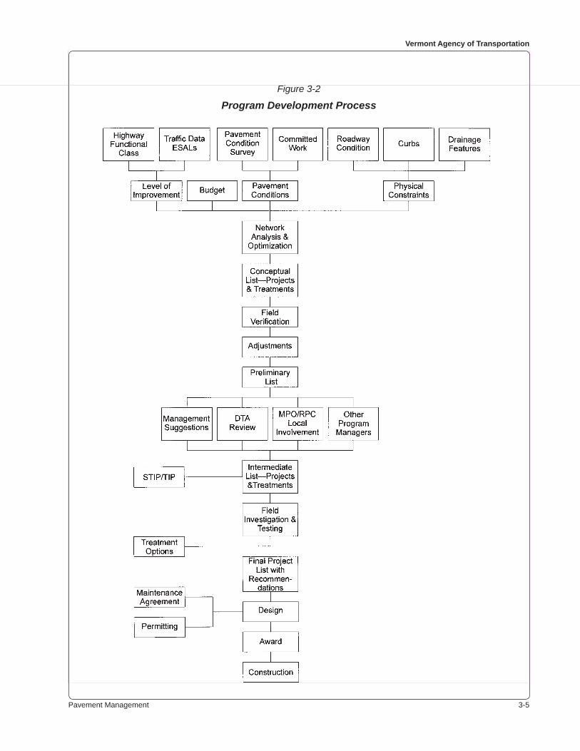
Pavement Management 3-�
vermont agency of transportation
Figure 3-2
Program Development Process
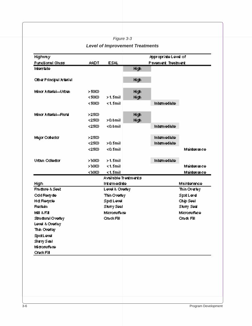
3-� Program Development
Figure 3-3
Level of Improvement Treatments
Pavement Management 3-�
vermont agency of transportation
Functional Class. The functional class assigned to each segment of highway is indicated on the “Highway Functional Classification Map” published by the Agency’s Policy and Planning Divi-sion. This information is maintained in the pavement management computer database.
Traffic Data. The volume of traffic for analysis and design purposes is maintained in the pave-ment management computer database. Updated data is obtained from the Highway Research Data Section. The estimated ESALs may be obtained from the same source.
For Interstate and NHS projects, a design year estimate of AADT and ESALs must be requested from the Highway Research Data Section.
3.2.4.2 Pavement Conditions
3.2.4.2.1 Field Surveys
Contractors are employed to assess and record surface conditions with automated equipment. The equipment measures and records ride quality, rutting, cracking, and the extent of patching.
Automated surveys are made on the Interstate Highway System (both directions, in the driving lanes only) in the odd-numbered years.
The State highways and Class 1 town highways are surveyed in the even-numbered years. Surveys are made only on the lanes in a northerly or easterly direction of travel.
Surface condition surveys are conducted only in the summer months after all effects of frost action are past.
Unit personnel make “windshield surveys” and on-road measurements to supplement and verify the data obtained by mechanical or automated means.
3.2.4.2.2 Condition Survey Practice
Ride quality (roughness) is measured continuously, then aggregated into 161-meter segments and expressed according to International Roughness Index (IRI) standards in m/km.
Rutting, cracking, and patching data is accumulated in the same 161-meter segments. Data is maintained on over 32 000 segments on the Interstates, the Class 1 town highways, and the State highways combined.
The Pavement Distress Manual, published by the Strategic Highway Research Program (SHRP), provides an interpretive aid and reference standard. The Data Collection Protocols established by FHWA are a national standard and guide for condition assessment. The protocols use roughness, rut depth and cracking as standard condition parameters. The parameters are classified according to severity and extent in establishing condition ratings.
For purposes of analysis, the Pavement Management Section classifies several common types of pavement distress into “low,” “medium,” “high,” and “extreme” categories. The types of distresses considered appropriate for analysis purposes are cracking, rutting, and roughness.
Cracking is measured in terms of severity and extent. The severity of cracking is classified rela-
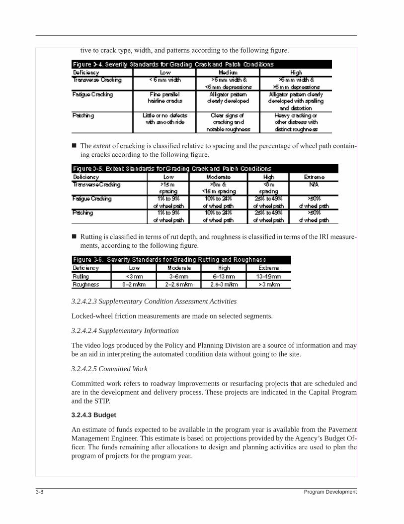
3-� Program Development
tive to crack type, width, and patterns according to the following figure.
The extent of cracking is classified relative to spacing and the percentage of wheel path contain-ing cracks according to the following figure.
Rutting is classified in terms of rut depth, and roughness is classified in terms of the IRI measure-ments, according to the following figure.
3.2.4.2.3 Supplementary Condition Assessment Activities
Locked-wheel friction measurements are made on selected segments.
3.2.4.2.4 Supplementary Information
The video logs produced by the Policy and Planning Division are a source of information and may be an aid in interpreting the automated condition data without going to the site.
3.2.4.2.5 Committed Work
Committed work refers to roadway improvements or resurfacing projects that are scheduled and are in the development and delivery process. These projects are indicated in the Capital Program and the STIP.
3.2.4.3 Budget
An estimate of funds expected to be available in the program year is available from the Pavement Management Engineer. This estimate is based on projections provided by the Agency’s Budget Of-ficer. The funds remaining after allocations to design and planning activities are used to plan the program of projects for the program year.
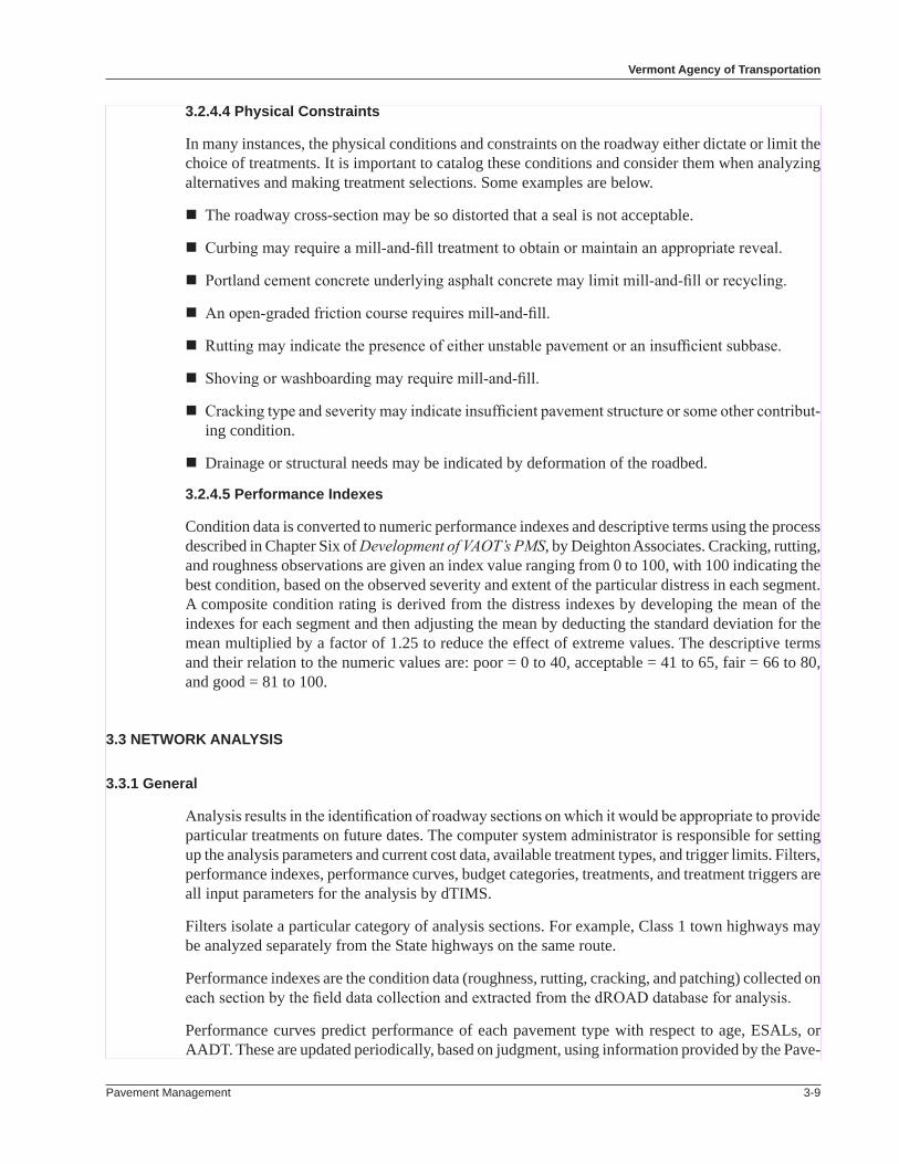
Pavement Management 3-�
vermont agency of transportation
3.2.4.4 Physical Constraints
In many instances, the physical conditions and constraints on the roadway either dictate or limit the choice of treatments. It is important to catalog these conditions and consider them when analyzing alternatives and making treatment selections. Some examples are below.
The roadway cross-section may be so distorted that a seal is not acceptable.
Curbing may require a mill-and-fill treatment to obtain or maintain an appropriate reveal.
Portland cement concrete underlying asphalt concrete may limit mill-and-fill or recycling.
An open-graded friction course requires mill-and-fill.
Rutting may indicate the presence of either unstable pavement or an insufficient subbase.
Shoving or washboarding may require mill-and-fill.
Cracking type and severity may indicate insufficient pavement structure or some other contribut-ing condition.
Drainage or structural needs may be indicated by deformation of the roadbed.
3.2.4.5 Performance Indexes
Condition data is converted to numeric performance indexes and descriptive terms using the process described in Chapter Six of Development of VAOT’s PMS, by Deighton Associates. Cracking, rutting, and roughness observations are given an index value ranging from 0 to 100, with 100 indicating the best condition, based on the observed severity and extent of the particular distress in each segment. A composite condition rating is derived from the distress indexes by developing the mean of the indexes for each segment and then adjusting the mean by deducting the standard deviation for the mean multiplied by a factor of 1.25 to reduce the effect of extreme values. The descriptive terms and their relation to the numeric values are: poor = 0 to 40, acceptable = 41 to 65, fair = 66 to 80, and good = 81 to 100.
3.3 network analysIs
3.3.1 General
Analysis results in the identification of roadway sections on which it would be appropriate to provide particular treatments on future dates. The computer system administrator is responsible for setting up the analysis parameters and current cost data, available treatment types, and trigger limits. Filters, performance indexes, performance curves, budget categories, treatments, and treatment triggers are all input parameters for the analysis by dTIMS.
Filters isolate a particular category of analysis sections. For example, Class 1 town highways may be analyzed separately from the State highways on the same route.
Performance indexes are the condition data (roughness, rutting, cracking, and patching) collected on each section by the field data collection and extracted from the dROAD database for analysis.
Performance curves predict performance of each pavement type with respect to age, ESALs, or AADT. These are updated periodically, based on judgment, using information provided by the Pave-
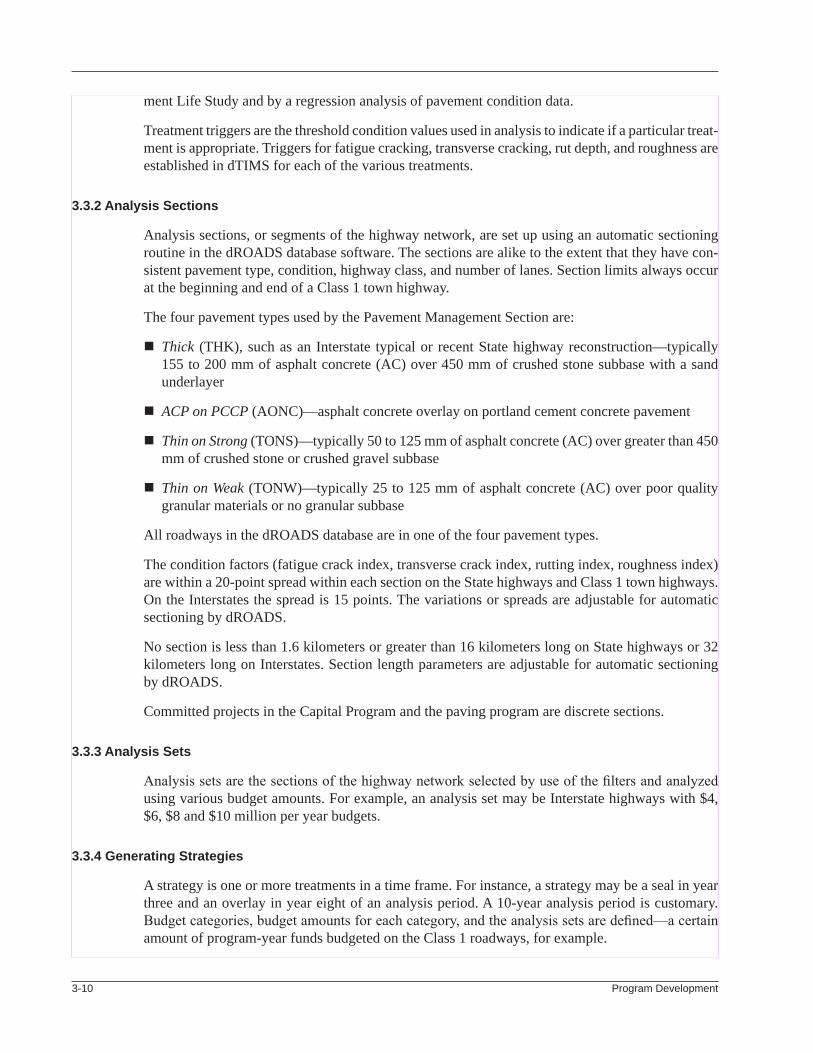
3-�0 Program Development
ment Life Study and by a regression analysis of pavement condition data.
Treatment triggers are the threshold condition values used in analysis to indicate if a particular treat-ment is appropriate. Triggers for fatigue cracking, transverse cracking, rut depth, and roughness are established in dTIMS for each of the various treatments.
3.3.2 analysis sections
Analysis sections, or segments of the highway network, are set up using an automatic sectioning routine in the dROADS database software. The sections are alike to the extent that they have con-sistent pavement type, condition, highway class, and number of lanes. Section limits always occur at the beginning and end of a Class 1 town highway.
The four pavement types used by the Pavement Management Section are:
Thick (THK), such as an Interstate typical or recent State highway reconstruction—typically 155 to 200 mm of asphalt concrete (AC) over 450 mm of crushed stone subbase with a sand underlayer
ACP on PCCP (AONC)—asphalt concrete overlay on portland cement concrete pavement
Thin on Strong (TONS)—typically 50 to 125 mm of asphalt concrete (AC) over greater than 450 mm of crushed stone or crushed gravel subbase
Thin on Weak (TONW)—typically 25 to 125 mm of asphalt concrete (AC) over poor quality granular materials or no granular subbase
All roadways in the dROADS database are in one of the four pavement types.
The condition factors (fatigue crack index, transverse crack index, rutting index, roughness index) are within a 20-point spread within each section on the State highways and Class 1 town highways. On the Interstates the spread is 15 points. The variations or spreads are adjustable for automatic sectioning by dROADS.
No section is less than 1.6 kilometers or greater than 16 kilometers long on State highways or 32 kilometers long on Interstates. Section length parameters are adjustable for automatic sectioning by dROADS.
Committed projects in the Capital Program and the paving program are discrete sections.
3.3.3 analysis sets
Analysis sets are the sections of the highway network selected by use of the filters and analyzed using various budget amounts. For example, an analysis set may be Interstate highways with $4, $6, $8 and $10 million per year budgets.
3.3.4 Generating strategies
A strategy is one or more treatments in a time frame. For instance, a strategy may be a seal in year three and an overlay in year eight of an analysis period. A 10-year analysis period is customary. Budget categories, budget amounts for each category, and the analysis sets are defined—a certain amount of program-year funds budgeted on the Class 1 roadways, for example.

Pavement Management 3-��
vermont agency of transportation
The software first predicts the future condition for each network section if nothing is done except restorative maintenance. The predicted condition in each year is checked against the treatment trig-gers. If it falls within the trigger zone, a treatment strategy is established for the section.
The condition prediction is reset, assuming the treatment occurs, and that treatment’s performance curve is used to again predict the future condition. If the future condition falls within a trigger zone, it suggests another treatment at that time. The process is repeated until reaching the end of the analysis period. A full array of all possible strategies is developed for each section.
If future roadway activity has already been identified and committed in a program (paving or capi-tal), the system administrator enters the planned treatment. The software restricts the options to the committed treatment in the committed year. The analysis then moves on to the next segment.
An economic analysis selects the best strategy for each section. Life-cycle costs and benefits are the economic factors. Life-cycle costs are calculated over the analysis period to include the cost of the treatments in the year they are applied. The cost stream is converted to present value, using a four-percent discount rate. Maintenance costs may be considered, if desired. Benefits are estimated using an area-under-the-curve approach.
Two other approaches to cost-benefit are available: net present value and vehicle operating-cost savings.
The present value of the benefits divided by the present value of the costs—the benefit-cost ratio—is computed for each strategy. The software uses the benefit-cost ratio to present a prioritized list of strategies for each section.
3.3.5 Performing optimization
An optimization technique is built into the dTIMS software that compares the various strategies in terms of their benefits and costs, based on an incremental benefit-cost analysis. The strategies with the higher benefit-to-cost ratios—those on the “efficiency frontier”—are considered workable. The alternative with the most benefits for the dollar invested is the “best” strategy. Its cost is deducted from the available budget. If the budget is insufficient, then a less costly (perhaps even do-nothing) strategy is adopted.
For further details on network analysis refer to the dTIMS Technical Guide.
3.4 ProGram of ProjeCts
3.4.1 General
The collection of “best” strategies is the first-cut (conceptual) program of projects. The Program Development Engineer modifies the first-cut program if necessary to alleviate scheduling problems. Combining adjacent sections into a viable contract length may override a theoretical program of treatments.
Projects on Class 1 town highways typically are the full length of significant street segments. Proj-ects on State highways have no arbitrary minimum length but preferably are at least five kilometers long.
3-�� Program Development
3.4.2 Conceptual Project list
The conceptual project list is generated at least three years in advance of the time that paving takes place. For example, FY 1999 State funds and FFY 1998 federal funds support paving work to be done in the summer of 1998. The project list for this work originates in the spring of 1995, based on condition information secured the previous summer.
Projects that were “bumped” from a previous year’s program are included in the list by indicating them to be “committed” projects in dTIMS.
The dTIMS software produces the list based on funding at the level estimated to be available in the program year.
The conceptual project list contains the following information for each project:
Name of the town in which the project is located Route on which the project is located Limits of work (beginning and end), expressed by location reference Treatment indicated as the highest benefit-cost within the available budget Cost estimate for the project (including engineering) as produced by dTIMS
3.4.3 Field Review and Verification
Field reviews should be performed on each project in the conceptual project list. The DTAs may join the field review or simply state their concerns, such as excessive potholing being experienced on a segment that was not selected for resurfacing. Conduct the field review as follows:
Review the beginning and ending locations to avoid leaving short lengths of poor pavement before reaching a relatively good area.
Note any short intersecting connector highway approaches, jug handles, etc., for possible inclu-sion.
In a joint review with local officials, confirm that there is no planned reconstruction or utility work on Class 1 roadways.
Review any high accident locations with an actual-rate-to-critical-rate ratio over 2.0 for obvious curative measures that could be included in the scope of the project.
Note scenic highway considerations.
Note any localized subbase failure or unstable pavement.
All of the information gathered from comments and by the field review is considered. As a result, the project may be deferred, the termini may be adjusted, different treatments may be selected, or a change in scope may be adopted.
3.4.4 Project Cost estimate
The dTIMS software computes a preliminary project cost based on the roadway area or the length of project, depending on the factor specified. If the scope of a project is different from the nominal project as defined by the software, it is necessary to manually compute the difference in cost. For
Pavement Management 3-�3
vermont agency of transportation
example, the cost of intersecting road segments (approaches) and any widening of the paved area needs to be added to the amount indicated by dTIMS.
The unit prices for the various treatments, which are in the software, need updating periodically based on experience.
A preliminary project list is the result of this review and analysis.
3.5 Comments anD suGGestIons
Input during program development is actively sought by the Program Development Engineer. The purpose of the input is to have well-coordinated Agency activity and full consideration of the views of those who are affected.
3.5.1 management Comments
The Pavement Management Engineer, the directors, and the Secretary of Transportation all receive input on the perceived needs and urgency of improvements to the system as they meet with individu-als and groups in the course of their duties. Based on this information, they may occasionally offer suggestions on priority and types of treatment.
3.5.2 other Comments
3.5.2.1 other Program managers
The activities in other Agency programs have considerable impact on the paving program. The pre-liminary project list is circulated to all Agency program managers who are invited to comment. It is imperative to avoid resurfacing a segment of roadway and then having it disturbed by another project shortly afterward. Thus, the Section maintains open communication with other Agency sections, particularly the roadway and bridge program managers, to be aware of their programmed work.
The Agency’s 5-Year Capital Program and the Statewide Transportation Improvement Program (STIP) provide scheduling information on planned projects. The Agency’s Preconstruction Project Management System (PPMS) has detailed information in its database on the status of all Agency projects.
Field review and consultation with regional planners and district administrators is an important part of arriving at a program of projects.
3.5.2.2 maintenance Districts
The maintenance districts receive annual visits from Program Development. These visits provide feedback on performance of previous projects and information on the district’s planned culvert and guardrail work. The DTAs have close insight into the current and future condition of their road-ways.
The DTAs receive the preliminary project list directly.
3.5.2.3 rPC/mPo
The Regional Planning Commissions (RPC) and the Metropolitan Planning Organization (MPO) receive regular visits aimed at hearing their needs and the public’s attitudes. During the visit, the
3-�� Program Development
RPC/MPO are briefed on the Agency’s goals, challenges, and opportunities relative to paving. The Program Development Engineer coordinates the visits with the appropriate regional planning coor-dinator in the Agency’s Policy and Planning Division.
The RPCs and the MPO receive the preliminary list from the regional planning coordinators in the Policy and Planning Division. All recipients may submit their concerns and any suggested changes.
3.5.2.4 local Government
It is essential to contact the local governmental units so they know when work is proposed on their Class 1 town highways. Paving work must be coordinated with utility work or street reconstruction. Street reconstruction will not likely be in the Agency’s database.
3.5.3 Consideration of Comments
All comments are considered and changes are made in the list as necessary to avoid conflicts or comply with worthy suggestions. The intermediate program list is the result of this review and comment activity.
3.6 IntermeDIate ProGram lIst
3.6.1 General
The intermediate list is provided to the Agency’s Policy and Planning Division in June of each year for inclusion in the draft STIP. The intermediate list is provided to the Pavement Management Engineer and to the manager of the other Agency programs for information and comment. To as-sist in arriving at the final list, the intermediate list is circulated to the Agency’s executive staff for information and comment.
Each affected community receives a letter advising of the proposed work. An example advisory letter is in the appendix. Those communities responsible for roadways nominated for Class 1 town highway projects are asked to affirm the projects.
3.6.2 Investigation and study
The pavement management data collection group makes a field investigation for each project on the intermediate list. The amount of investigation necessary to support a treatment selection is relative to the cost of the treatment options. Physical conditions may remove the need for investigation; for example, the presence of curbing may require mill-and-fill treatment.
For each project the pavement management data collection group submits a report to the Program Development Engineer. The report summarizes the field investigation results and makes a recom-mendation on the appropriate treatments within the project area.
Those project areas that have good roadbed structure are reviewed for required pavement thickness. Recommendations are based on providing the appropriate pavement depth for the design ESALs. The combination of physical data and information from route logs and as-built plans provides the basis for making an informed treatment recommendation.
Investigation techniques that may be applicable include the following.
Pavement Management 3-��
vermont agency of transportation
Coring, using nominal 50-mm bits, extends the full depth of the existing pavement. The pavement materials are removed, the pavement thickness is measured, and the hole is backfilled with patch material. Visual examination is the usual mode of study.
Analysis of binder characteristics and aggregate properties may be requested from the Agency’s Materials and Research Section, particularly if rutting or shoving is observed. If so, a recommen-dation is required on whether to leave any unstable material in place and bridge it or to remove the unstable material and replace it. The recommendation is based on information gained from coring.
Both the shoulders and driving areas may be cored to determine the pavement thickness and quality. The frequency of coring is usually one core in the right wheel track of the driving lane at 320-meter intervals. Special coring efforts are made in cases of uncertainty or considerable variation in observed conditions.
Test pits are dug to observe the stratification and quality of pavement, subbase, and subgrade, if the cause of extreme rutting or shoving is in question.
Testing with a falling weight deflectometer (FWD) indirectly determines the bearing capacity (composite structural number) of the materials in the roadbed. Precise sensors measure the deflec-tion of the roadway materials in response to the impact of weights dropped from varying heights. The information aids in determining the appropriate total pavement depth.
The DARWIN overlay design software is used to review the adequacy of the existing pavement structure or, alternatively, to design a new pavement structure. Data needed to support the analysis is provided by the coring and FWD testing. Specific information required is the pavement depth, pavement temperature at mid-depth, and the deflection data from the FWD test.
Using procedures outlined in the AASHTO Guide for Design of Pavement Structures, the software estimates the subgrade modulus from the pavement and deflection data, and the existing struc-tural number is derived. The software computes the design structural number using the design ESALs.
The difference between the existing and design structural numbers is an indication of the ad-ditional pavement thickness (overlay) required for the expected axle loading.
Refer to the manual provided with this AASHTO software product for details on its functions and capability.
The ELMOD software from Dynatest Inc. may be used for an alternative overlay design. ELMOD is occasionally used to analyze the compaction in subbase layers during construction.
The profilometer (“dipstick”) is used to gather detailed data on the roughness of the existing pavement. The Dipstick 2000 is manufactured by Face Construction Technologies, Inc. The device precisely measures the difference in elevation between two closely spaced points on the pavement surface. The result is accurate rut depth and deformation information. Refer to the manual provided with the equipment for details on its functions and use.
Sites for calibration of the “Mays meter” (see below) are surveyed with this device. Several sites, on roadways of varying degrees of roughness, are strategically located on the State highway system.
The “Mays meter” is used to gather data on the roughness of the roadway surface. Before use
3-�� Program Development
it must be calibrated at one of the 300-m sites established with the “dipstick.” The Mays meter is trailer-mounted and accumulates the number of 2.5-mm disturbances that it encounters while passing over the roadway at three prescribed speeds. Processing this data through a computer program results in (highest, lowest, and average) IRI values for 0.32-km segments.
Historical data, including date of construction, dates of resurfacing, and the materials used, are obtained from the route logs, the as-built plans, materials data, and construction records. The bituminous materials unit of the Agency’s Materials and Research Section is a good source of information. The DTA, the maintenance supervisors, and the resident engineers are also good sources.
3.6.3 treatment selection
The engineering aspects of treatment selection are highly refined because of the current capability of high-speed data acquisition and analysis, new data sources, a proliferation of available treatments, maintenance considerations, and coordination with other Agency programs.
The selection process requires consideration of the highway classification, the physical conditions, the LOI arrays of allowed treatments, and the funding available. The analyst follows a process of elimination and optimization, starting with the treatment suggested by dTIMS and shown in the intermediate project list.
Often, the most appropriate treatment for a project becomes apparent after consideration of the available information. For example, a mill-and-fill treatment may be the only option for a Class 1 resurfacing project due to curb reveal, drive entrances, and drainage features. However, the most appropriate treatment is not always so obvious.
It is quite challenging to decide to crack-and-seat a lengthy section of PCC roadway when consid-ering the cost, the disruption to traffic, and the lack of high-quality data on life expectancy for that alternative. Conversely, how a level-and-overlay will perform on a roadway with PCC under it is known, and the analyst is optimizing the benefit by selecting this option.
There are many variables to consider when selecting a treatment. The more information available, the more appropriate the treatment selection will be. Testing the existing roadbed for structural capacity is an example of the information required to make an informed decision.
The process is further complicated if analyzing a section of collector highway that has been re-constructed with a strong subbase. The most cost-effective treatment may be a cold-recycle-and-overlay (CROL), a treatment not consistent with the LOI matrix. The CROL treatment may offer considerably longer service life. To propose such a treatment requires a rudimentary analysis of cost and benefit in terms of long-term network condition. The dTIMS software may aid in this analysis. Concurrence of the Pavement Management Engineer is required to include the additional treatments in the analysis.
Once the active options (project treatments) are identified, the analyst selects a preferred alternative. The treatment does not need to be uniform throughout the length of the project, although exceed-ingly short segments of different treatments are expensive and poor engineering practice. Budget limitations are a significant consideration in the selection process.
Ideally, the treatment selected should be that which provides the highest benefit-cost ratio. If the funds are insufficient, the next best treatment is considered.
Pavement Management 3-��
vermont agency of transportation
The most cost-effective treatments typically occur early in the life of a pavement. The analyst is faced with a difficult decision when the project and treatment with the highest benefit-cost ratio is selected, and this is a roadway in fair condition that would benefit from an overlay, while a section of roadway in very poor condition is not selected because the condition is so poor that the benefit-cost ratio is less attractive than those for other projects.
The LOI guidelines suggest maintaining all roads to a minimum level of service. There is a balance that takes place when considering the long-term health of the network and issues of safety, cost to the maintenance districts to maintain ride, and inconvenience to the traveling public. These issues are not represented on the “efficiency frontier” but are real considerations for the analyst.
The end result of the analysis is selection of a preferred treatment from the treatment options listed in the appendix. The analyst forwards a report with recommendation to the Program Development Engineer.
3.7 fInal ProjeCt lIst
After consideration of comments on the intermediate list, the information obtained in the field inves-tigation and treatment design activity, the final project list is established. In the final list the project scope and location is firm, and the cost estimate considers all aspects of the work. An example final list is in the appendix.
3.8 Program approval
The final project list requires the approval of the Pavement Management Engineer. The Engineer ensures that the proposed program of projects meets the objectives of the Section and the Agency and is within the anticipated budget. Once approved, the final list is the basis for including the pav-ing projects in the STIP update and proceeding with formal project definition.
The Agency’s Policy and Planning Division receives the final list in September of each year for in-clusion in the STIP update. The update is a plan for the proposed use of federal funds in the federal fiscal year beginning October 1 and the next two federal fiscal years.
The final list may require adjustment to fit the amount of funds allocated during the STIP formulation process. In this process, conducted at executive staff level, changes in letting schedules or preliminary cost estimates for large projects may cause significant shifts in funding between one program and another. Due to its inherent flexibility, the paving program may be substantially affected. Projects may need to be added or eliminated to fit the funding anticipated to be available.
The final list is sent to the Agency’s Programming Engineer to use as reference in establishing the new projects in PPMS. In addition, the Program Development Engineer prepares a form PAR/DB for each project on the list. An example form is included in the appendix.
A letter is sent to each affected city, town, or village advising of the planned project, its scope, and the planned date of construction. An example letter is in the appendix.
Those communities selected for Class 1 town highway projects must sign a formal maintenance agreement that defines the responsibilities of the Agency and the local government during and after construction. Design is not to proceed without the execution of this agreement. An example of the agreement is in the appendix.
3-�� Program Development
3.9 ProjeCt Data for DesIGn
3.9.1 General
Once the final list is established, the Program Development Engineer forwards design data for each project to the Pavement Design Engineer as soon as the data becomes available. Forward the data immediately for projects requiring no field investigation. Field investigation and project definition activity occur within the time frames shown in Figure 3-1, on Page 3-4.
The designer needs certain information to develop the projects that are on the final list. This infor-mation is required before the beginning of any sort of design activity. The Program Development Engineer must define the project by providing definite instructions and the required data to the de-signer so that the project is designed as it was envisioned during the program development phase.
The information is provided in a folder, which upon transmittal becomes the official “design folder” and indicates that project responsibility has been transferred from the Program Development Unit to the Pavement Design Unit.
Although not necessarily an exhaustive listing, typical information that is provided to the designer is highlighted in the following section.
3.9.2 required Data
The Program Development Engineer provides the following data on each project to the Pavement Design Engineer, who then forwards it to the assigned consultant designer. Much of this informa-tion is normally consolidated and shown on the pavement design recommendation. See the example design recommendation in the appendix.
Project name—the towns or cities in which the project is located. Indicate if the project is on Class 1 town highway.
Project number—as assigned by the Agency’s Programming Engineer. It indicates the applicable design standard (IN, NH, or STP).
Location—indicated by color coding on a copy of the route log, with mile/kilometer location. Indicate the resultant project length.
Treatment—with locations, if more than one treatment. Treatment recommendations include the binder type, the mix type, and the performance specification to be used. Treatment recommenda-tions must be initialed by the Pavement Management Engineer and the Program Development Engineer. Typical treatment descriptions are shown on the example of the spreadsheet “Pavement Management Project Information” in the appendix.
Traffic data—AADT, DHV, ESALs for the year of construction and the design year. Rough estimates of ESALs only.
High accident locations—locations only. The designer is expected to research details from the Agency’s traffic database.
Bridge locations. The designer is to contact the Agency’s Structures Engineer for guidance on each indicated location.
Railroad crossing locations. The designer is to contact the RAPT Division for guidance.
Core information—list of information obtained from coring of pavement. It is required only
Pavement Management 3-��
vermont agency of transportation
where MAF or CROL treatments are programmed.
DARWIN output—overlay thickness determination.

3-�0 Program Development
Pavement Management 4-�
Chapter FourProject Definition
Figure 3-1, on Page 3-4, shows the time at which project definition occurs.
4.1 Design guiDelines
4.1.1 Design Standards
Designs for projects on the NHS (National Highway System) and Interstate follow the VAOT 3R Policy. If the 3R Policy cannot be met for an NHS project, then the “Interim Policy on Resurfac-ing”—also called the “2R Policy”—is used as a preventive maintenance policy. The “Interim Policy” is in the appendix.
Designs for projects that are not on the NHS follow the STP design objectives and policy—“STP Paving Projects—Design Objectives” and “Interim Policy on Resurfacing” (or “2R Policy”). Both of these documents are in the appendix.
Pavement Management uses the existing roadway width and geometry to avoid the need of acquir-ing additional right-of-way. Additional safety measures, such as extending guardrail, may be used to avoid the need for right-of-way acquisition; design exceptions may be sought, etc.
4.1.2 Design Guidelines
Design guidelines are listed below.
VAOT 3R Policy “Interim Policy on Resurfacing” (“2R Policy”)—in the appendix “STP Paving Projects—Design Objectives”—in the appendix A Policy on Geometric Design of Highways and Streets—1994, AASHTO (the “Green Book”) Roadside Design Guidelines—Approved 1988, AASHTO “Draft Policy on Shoulder Paving”—in the appendix ManualonUniformTrafficControlDevices(MUTCD) “Pavement Marking Guidelines” “Guidelines for Bridges on STP Projects”—in the appendix
4-� ProjectDefinition
In addition, the Agency provides:
Crosswalkguidelines. Item estimating guidelines. MiscellaneousproceduralguidancefromContractAdministration. StandardSpecifications. Use the version cited in the project’s design folder. General special provisions. Use the current version. Supplementalspecifications.
Projects use metric dimensioning except for mile markers and the length of the project, which is expressed in both metric and English units.
4.1.3 Design Exceptions
A design exception may be required if designed project features are not in conformance with the 2R or 3R policies, as they are applied. (See Section 4.1.1.)
Design exception requests are submitted with the preliminary plans. An example design exception request is in the appendix. It includes the flowchart for the design exception process.
Design exceptions must be approved by the Pavement Management Engineer, the Director of Con-struction and Maintenance, and the Secretary of Transportation. In addition, the FHWA must approve design exceptions for Interstate projects.
Approvals are based on the extent of historical, archeological, wetland, and social and economic impacts and on the avoidance of significant increases in scope or cost.
4.2 Design Data
Before providing the design folder to the consultant (Chapter Three), the project manager confirms or corrects information in the folder and provides some additional information:
PavementMarkings. The project manager extracts marking information for the project area from the pavement marking log provided by Traffic Operations. The project manager confirms crosswalk locations with Traffic Operations.
HAL (High Accident Locations). The project manager confirms the HAL locations in the design folder by comparing them with the information in the current “Yellow Book” (High Accident Locations) provided by Highway Traffic Research.
Bridge Information. The project manager collects bridge information from the Structures Section and Maintenance Section, such as planned deck work and the desired scope of the resurfacing project, and forwards it to the consultant.
Scenic Highways and Byways. The project manager verifies whether the project is on a scenic highway or byway by checking the current list provided by the Planning Division. A copy of the list is in the appendix.
Utilities. Pavement Management provides the Utilities Unit with a list of projects after the final program list is developed, as described in Chapter Three. The Utilities Unit reviews the list and provides the information about utility locations and utility company plans and actions to Pavement Management. The project manager verifies that the latest information is in the design folder.
Pavement Management 4-�
Vermont Agency of Transportation
Signs and Signals. The project manager requests Traffic Operations to review its inventories to identify signal loops that will be rendered ineffective by the project, required upgrades for NHS routes, etc., as well as a sign inventory for the project. The project manager forwards the infor-mation to the consultant.
RailroadCrossings. The project manager confirms or corrects the information in the design folder by checking with the RAPT Division.
TrafficData/ESALs. The project manager confirms that the information is in the design folder.
4.3 scope Definition
The Section’s Pavement Design Engineer is responsible for coordinating the activities involved in scope definition.
4.3.1 Surfacing
The Section’s Program Development Engineer develops project design recommendations. The rec-ommendations are summarized on the “Pavement Management Project Information” spreadsheet. Examples of both the recommendation and spreadsheet are in the appendix.
During project definition, the recommendation for the type and depth is confirmed or corrected for field conditions. The Pavement Management Engineer approves all changes.
4.3.2 Shoulders
Shoulder treatment guidance is in the “Draft Policy on Shoulder Paving,” included in the appen-dix.
A project usually includes overlaying existing paved shoulders or paving gravel shoulders. Existing paved shoulders typically receive full-width leveling and a top course. A project may include the removal of 75 to 100 mm of existing material and replacement with subbase or bituminous mix.
Shoulders usually are backed with Aggregate Shoulder. However, topsoil is used for backing in lawn areas, and milled bituminous concrete is used if it is suitable and available.
A minimum of 1200 mm of shoulder for bicycle use is desired. However, do not widen the existing roadbed to obtain additional shoulder width.
4.3.3 Safety Elements
4.3.3.1 Guardrail
On 2R projects, nonstandard guardrail typically is upgraded to galvanized “W” beam if the criteria in “STP Paving Projects—Design Objectives” (in the appendix) are met. Weathering steel can be used in aesthetically sensitive areas. Other rail types may be selected on a case-by-case basis. Guardrail end treatments are selected to meet field conditions.
4.3.3.2 Signs
On 2R projects, only signs associated with pavement markings are replaced on the mainline. On
4-4 ProjectDefinition
NHS projects, all signs are replaced on the mainline. On either type of project, all Stop signs and legal load-limit signs are replaced on roads intersecting the mainline.
4.3.3.3 Signals
Moderate or major signal work is rarely performed on a Pavement Management project, although some may occasionally be included to treat a HAL. Loop detectors, however, are frequently replaced in kind if disturbed during project construction.
4.3.3.4 Roadside Obstacles
On 2R projects, new guardrail installations may be placed, and existing installations may be adjusted or extended. See “STP Paving Projects—Design Objectives” in the appendix. NHS projects must provide for adequate clear zones.
4.3.3.5 Intersections
If intersections are to be reconfigured, Traffic Operations typically provides the guidance. The guidance should be in accordance with the “STP Paving Projects—Design Objectives,” in the ap-pendix.
4.3.4 Parking Provisions
Parking provisions are included in a project if the existing pavement markings will be obliterated during the project’s construction. A city or village may elect to place the markings on Class 1 town highway projects.
Use the MUTCD (ManualonUniformTrafficControlDevices) and State law for layout guidance. A copy of Title 23, Section 1104, is in the appendix. A municipality may supplement the statute with an ordinance, etc.
4.3.5 Hals
For non-NHS projects, the HAL treatment policy is in the “Interim Policy on Resurfacing,” in-cluded in the appendix. The consultant must contact Highway Traffic Research, Technical Services Division, for the required accident reports, perform the appropriate analyses, and submit them to the Pavement Management Section for approval. All HALs are treated on an individual basis in consultation with the Pavement Management project manager and in accordance with the example HAL analysis in the appendix.
4.3.6 Pavement Marking
All pavement markings are in accordance with the latest edition of the MUTCD. Centerline (passing zones) information is provided by Traffic Operations, as indicated earlier. See the VAOT 3R Policy for lane widths for both NHS and non-NHS roads. Replace existing pavement markings according to current standards. See the “Pavement Marking Guidelines,” which can be obtained from the Pave-ment Management Section, for markings required during construction. Generally, thermoplastic is used for permanent markings, and paint is used for temporary markings.
4.3.7 Drainage
On 2R projects, drainage improvements typically are limited to rehabilitating drop inlets, improving
Pavement Management 4-�
Vermont Agency of Transportation
pavement crown, cleaning ditches, and other “surface” improvements. More extensive improve-ments may be made on NHS projects. For details, see the VAOT standard drawings and the Standard SpecificationsforConstruction.
4.3.8 Bridges
Bridge treatments are limited to those recommended by Structures. Typical work is as follows:
If the deck is overlayed, the project may include cold planing or a simple overlay. 3-cable rail is replaced. (Other existing bridge rail may be upgraded on a case-by-case basis.) Blunt ends of bridge curb are flared back. If bridge railing is upgraded, the associated approach railing is upgraded. Joints and joint seals are repaired or replaced if needed.
For 2R projects, see the “Guidelines for Bridges on STP Projects,” in the appendix.
4.3.9 Scenic Quality
Scenic quality is addressed project by project. Guardrail, shoulders, etc., may be modified if concerns are raised by the affected municipalities or other interested parties.
4.3.10 Americans with Disabilities Act (ADA)
All projects are required to conform with the ADA. See the ADA and the VAOT standard draw-ings.
4.3.11 Railroad Crossings
The RAPT (Rail, Air and Public Transportation) Division, in conjunction with the railroad com-panies, determines railroad crossing treatments. Options for a crossing run from no treatment to a new prefabricated crossing.
4.3.12 Sewer, Water, and Telephone
Special provisions for utilities are coordinated and handled by the Utilities Unit. On Class 1 town highway projects, the consultant is required to contact local utility owners for locations of existing surface utilities so that they may be included and identified on the project plans. Contacts are made and preliminary treatments are discussed at the Class 1 predesign meeting.
4.3.13 Design Exceptions
The consultant must identify the need for design exception requests and compose and submit design exception documents. Design exceptions should cover all variations from established policies and guidelines.
4.4 EnVIROnMEnTAl PERMITTInG
The Pavement Management Section typically is not directly involved in the environmental permit-ting process. The documents for requesting a categorical exclusion are prepared by a consultant. The

4-� ProjectDefinition
documents can vary from a letter of “no effect” to those needed for a full historical and archeologi-cal review. An example set of documents is in the appendix. The consultant submits the documents to the Environmental Permitting Chief. If the submission is accepted, it is sent to the FHWA by Permitting.
4.5 scenic consiDerations
On all “scenic highway” projects, the project manager must confer with the Regional Planning Commission (RPC) to determine the nature of scenic concerns. Scenic areas may require the place-ment of weathering-steel box-beam guardrail, special treatment of drainage inlets, special shoulder materials, special signing, etc.
4.6 FInAnCE AnD MAInTEnAnCE AGREEMEnTS
A finance and maintenance agreement is an agreement between the Agency and a village or city that sets forth the conditions under which a project is undertaken. A finance and maintenance agreement is needed only for Class 1 town highways. Generally, the agreement covers the responsibilities of the municipality in regard to right-of-way encroachments, utility relocation, maintenance of traffic control devices installed during the project, road maintenance during possible suspension of the project in the winter, etc., in exchange for the completion of the project by the State. The agreement is based in part on Title 19, V.S.A., Section 306a. A copy of a finance and maintenance agreement and Section 306a are in the appendix.
A finance and maintenance agreement is processed as follows:
1. Pavement Management provides Contract Administration with a list of project names, numbers, and limits after the final project list is developed. (See Chapter Three.)
2. Pavement Management requests that Contract Administration prepare a finance and maintenance agreement for a project.
3. Contract Administration composes the agreement and sends it to the Auditor and Assistant At-torneys General for review and to Pavement Management for content review.
4. Contract Administration sends the agreement to the municipality for signature.
5. The agreement is signed and dated by the Secretary of Transportation.
Design may proceed only if the agreement is executed.
4.7 RAIlROAD AGREEMEnTS
A railroad agreement is an agreement between the Agency and a railroad company that has a crossing within the project limits. An agreement is required if the construction will foul typical rail operations as determined by the RAPT Division, often in consultation with the affected railroad. The agreement generally covers the type of treatment for the railroad crossing; the responsibilities for the work; and, if the work is performed by the State’s contractor, insurance requirements, provisions for en-tering the railroad’s right-of-way, permitting, and safety during construction. An example railroad agreement is in the appendix.

Pavement Management 4-�
Vermont Agency of Transportation
A railroad agreement is processed as follows:
1. The Program Development Engineer sends a list of the projects with railroad crossings to the RAPT Division after the final project list is developed. (See Chapter Three.)
2. RAPT contacts the railroad company to determine the type of treatment for the crossing.
3. The railroad company elects either the State or itself to perform the work and relays the decision to the responsible RAPT project manager.
4. Pavement Management provides the project’s name, number, EA (expenditure account) number, description, location, and plan sheets, if available, to Contract Administration and requests that Contract Administration compose the agreement.
5. Contract Administration composes the agreement and sends it to the Auditor, Assistant Attorneys General, RAPT, and Pavement Management for review.
6. Contract Administration sends the agreement to the railroad for signature.
7. Contract Administration sends the agreement to the Secretary of Transportation for signature and dating.
8. The agreement becomes part of the contract special provisions for the project.
If the treatment is a surface treatment, the project manager takes the lead for the State. If the treat-ment consists of safety improvements, the RAPT Division takes the lead for the State.
4.8 UTIlITy AGREEMEnTS
Utility agreements are agreements between the State and utility companies or towns as to whether utility adjustment or relocation is needed because of a project, who will perform the adjustment or relocation, and the conditions regarding right-of-way access and use. The agreements are sum-marized in the project’s special provisions. Examples of letters and special provisions are included in the appendix.
For Class 1 projects, utility adjustments are paid for under the contract.
For a State project that affects a town, the Utilities Unit informs the officials of the town that the town may need to adjust its utilities. After the Utilities Unit receives the preliminary plans, it contacts the town and begins writing the utility agreement.
For other utilities on a State project, the Utilities Unit researches preliminary plans to identify the utility companies that are affected and contacts them.
The Utilities Unit writes the special provisions and sends them to Contract Administration.
4.9 COORDInATIOn REQUIREMEnTS
A letter is sent from Pavement Management to a municipality affected by a State highway project when the final program list is approved. (See Chapter Three.) The letter receives wide distribution: Regional Planning Commission, DTA, Planning’s regional planner, program managers, Materials and Research, Construction, etc. An example letter is in the appendix. In addition, predesign meetings
4-� ProjectDefinition
are held with municipal officials for Class 1 town highway projects. (See Section 4.10.)
The annual program is reviewed with the Construction Section to obtain its advice.
The project manager can promote coordination by:
Checking with the program managers of structures and roadways to coordinate with the capital programs.
Checking with the affected DTA to coordinate with the bridge membrane program, guardrail program, etc.
Checking with the Policy and Planning Division’s regional planning coordinator and STIP coor-dinator.
Checking with affected MPOs (Metropolitan Planning Organizations) to ensure that the project is on the TIP.
4.10 PREDESIGn MEETInGS
The Project Design Unit conducts a predesign meeting with all of the consultants engaged in an an-nual program to provide policies, procedures, example plans, initial assignments, plan distributions, VAOT expectations about timeliness, etc. VAOT Environmental Permitting attends the meeting to provide information about environmental matters. The meeting is informational rather than techni-cal and is not project specific.
The consultant conducts predesign meetings with municipalities included in Class 1 projects, as mentioned in Section 4.09. The meetings are held to discuss the intent and goals of a project and to address initial concerns of the municipal officials.
Pavement Management 5-�
Chapter FiveProject Plan Development
5.1 Consultant ContraCting
Most projects are designed by consultants. Consultants that are designing projects begin at the preliminary estimate stage and continue through field survey and plan preparation. The work in-cludes obtaining environmental clearances (primarily, confirming that there is no impact from the project).
Consultants may also be contracted to review shop drawings. Shop drawing review is limited to the review of bridge-rail fabrication drawings.
5.1.1 scope of Work
The scope of work for most Pavement Management projects includes resurfacing and minor safety and drainage work. Urban projects typically include sidewalk ramps and often include other work related to urban road features.
5.1.2 selection
Selecting a consultant for a project consists of the following:
1. The Pavement Management Section evaluates past performance of eligible consultants, along with the geographical areas usually covered by the consultants relative to the project location. Two consultants are invited to offer proposals on Interstate projects. Other projects usually are assigned to a particular consultant.
2. The Section’s Pavement Design Engineer requests a design cost estimate and schedule from the selected consultants and provides any available information for a proposal. A request letter is in the appendix.
3. The consultants submit the cost estimates and schedules. The consultants should review the project in the field prior to submitting the material.
4. The Pavement Design Engineer compares the estimate and schedule from each consultant with those that are desired by the Agency and determines whether the two sets of information are suf-ficiently close to proceed.
5-� Project Plan Development
5. A consultant is selected to perform the work.
6. The Pavement Design Engineer assigns a project manager.
7. The Section provides a notice to proceed to the consultant, and the consultant begins designing the project. An example notice to proceed is in the appendix.
5.1.3 administration
After the notice to proceed is issued to the consultant, the Pavement Design Engineer updates the financial tracking spreadsheet for design work flow, which is internal to the Pavement Management Section. A example spreadsheet is in the appendix.
The project manager updates the PPMS (Preconstruction Project Management System) at the time design authority is issued to the consultant:
Screen35. Enter consultant’s name.
Screen444. Enter the design begin date for Activity 180. The begin date is the date on which the notice to proceed is issued to the consultant.
5.2 PreParation of Plans
5.2.1 information sources
VAOT provides a variety of information for plan preparation if it is required or requested:
Project folder (Chapters Three and Four) Standards CADD seed and detail files (from the VAOT computer bulletin board) Sample plans Utility information on municipal projects
The consultant designer secures all other needed information by research or field survey.
5.2.2 Plan set Makeup
5.2.2.1 general
The purpose of plans is to provide construction engineers and technicians and contractors with suf-ficient information to complete the desired construction. To ensure consistent interpretation of the plans, each sheet should have a standard format and content, and the sheets should be assembled in the same sequence on all projects. Sheets may be combined to reduce the number of sheets on smaller projects.
This section presents guidelines for plan preparation to ensure that construction plans are clearly and uniformly prepared by designers for correct interpretation during construction. General guidelines are:
All plan sheets are drawn and read with their major dimension in a horizontal plane. Metric logos are required on all sheets.
Pavement Management 5-�
Vermont agency of transportation
The corner card must be completed on every sheet.
Quality control of the plans is achieved through the reviews at the various plan stages.
5.2.2.2. title sheet
5.2.2.2.1.General
A title sheet is required for each project or separate contract. It is the first sheet in each set of plans. Items to be included on the title sheet are:
Project location sketch Project area map Project location and description Traffic data Superpave design data Conventional symbols Statement indicating the applicable version of the Standard Specifications for Construction Control block data Notes Signatures of the approving authority
Follow the format shown for the sample title sheet in the appendix for all single project plans. A title sheet for multiple-project contracts is also in the appendix. It summaries the applicable single-project title sheets.
5.2.2.2.2. Project Location Sketches
The project location is indicated by two sketches in the upper right-hand corner of the sheet. One sketch shows the location within the State and county. The other shows the location within the re-gional highway network. It may be traced or reproduced from a State road map. The regional sketch (vicinity map) includes a north arrow and scale. The regional sketch should be drawn so that the north arrow points to the top of the sheet. Items that should be clearly shown on the vicinity map are town, county, and state lines; major rivers; lakes; cities and villages; and route numbers (including town highways) of all highways abutting or in the immediate vicinity of the project.
5.2.2.2.3. Project Area Map
The project area map is a general alignment plot of the project at the largest practical size. The map shows the adjacent and connecting highway network, adjacent towns, and north arrow. All roads, rivers, and significant topographic features should be clearly labeled. Arrows should be used to show the direction of flow of all rivers and streams. An arrow, route number, and destination should be shown at the end of the portion of each major road that is shown on the map. Town, county, state, and country lines should be shown.
The following types of construction are labeled as indicated, with lettering parallel to the bottom border and arrows indicating the location of the project. The nomenclature below is for metric sta-tioning. Kilometer markers may be used as applicable or directed.

5-� Project Plan Development
Project and/or contract limits
Sta. 25+000.00 Begin Project STP 9999(1)S
Sta. 26+000.00 End Project STP 9999(1)S
Adjacent projects or contracts should be indicated with the year built, if pertinent.
Gap within a project not requiring construction effort
Sta. 72+048.52 Stop Project
Sta. 72+050.96 Resume Project
Bridge to be constructed
Sta. 25+027.42 Stop Roadway—Begin Bridge
Sta. 25+179.82 End Bridge—Resume Roadway
Railroad grade crossing to be constructed
Sta. 72+048.52 Stop Roadway—Begin Railroad Crossing
Sta. 72+050.96 End Railroad Crossing—Resume Roadway
All stationing should be tied to the VAOT route logs at the beginning and end of the project and at other fixed points, such as side roads and bridges.
5.2.2.2.4. Project Location and Description
The project location and description is centered beneath the preprinted sheet heading.
The location and description of the project should agree with the description submitted by Program Control in programming the project with the FHWA. The project manager provides this information to the designer.
The town, county, and route number should appear on separate lines directly beneath the heading. The lettering size and style should be identical with that used in the heading. The town highway class designation should appear on a separate line after the route number.
In the detailed project location, all distances are given in meters to two decimal places and usually should follow the example below.
“Beginning in Jamaica at a point 5423.48 m north of the Townshend/Jamaica town line at Sta. 5+423.489 (MM 3.370) and extending northerly along Vt. Route 30 for a distance of 14 307.27 m to a point in Winhall at Sta. 3+445.606 (MM 2.141).”
Pavement Management 5-5
Vermont agency of transportation
The location should normally be referenced to the southerly or westerly town line for all State high-way and Interstate projects. References for town highway projects usually should be to the town line or the westerly or southerly terminus of the town highway.
The project length is shown in kilometers and broken down into roadway, bridges, and railroad crossings, if construction is required. The lengths provided should agree with all stationing and equations provided on the project area map and should read as follows:
Length of Roadway 3763.00 m Length of Bridges 37.00 m Length of Railroad Crossings 3.00 m Length of Project 3803.00 m
The project description should identify the principal construction elements of the project and usually should follow the format of the example below.
“Work to be performed under this project includes cold planing, resurfacing of the existing highway with a shim/leveling course and wearing course, new pavement markings, drainage improvements, safety improvements, and incidental items.”
5.2.2.2.5 Traffic Data
Traffic data is provided by Traffic Research and includes:
19__ ADT Average daily traffic in the year project is open to traffic. 20__ ADT Average daily traffic in design year. 20__ DHV Design hour volume in design year. D Percentage of traffic in predominate direction in the design hour. T Percentage of truck traffic in design hour. V Design speed.ESAL Equivalent single-axle loading.
The design year is normally 10 years beyond the date that the project will be opened to traffic.
5.2.2.2.6 Conventional Symbols
The conventional symbols are preprinted on the title sheet and normally require no modification. Additions to the list may be made as required.
5.2.2.2.7 Control Data Block
The vertical and horizontal datums, if applicable, on which the survey for the project is based are shown in the control data block to the right of the conventional symbol block.
5.2.2.2.8 Notes
General notes for the project are placed to the left of or above the corner card. The current StandardSpecifications must be referenced in the general notes.
Notes usually must be in metric units. Do not mix metric and English units.
5.2.2.2.9 Signatures
The corner card is filled out with the project name and construction number and the name of the project manager.
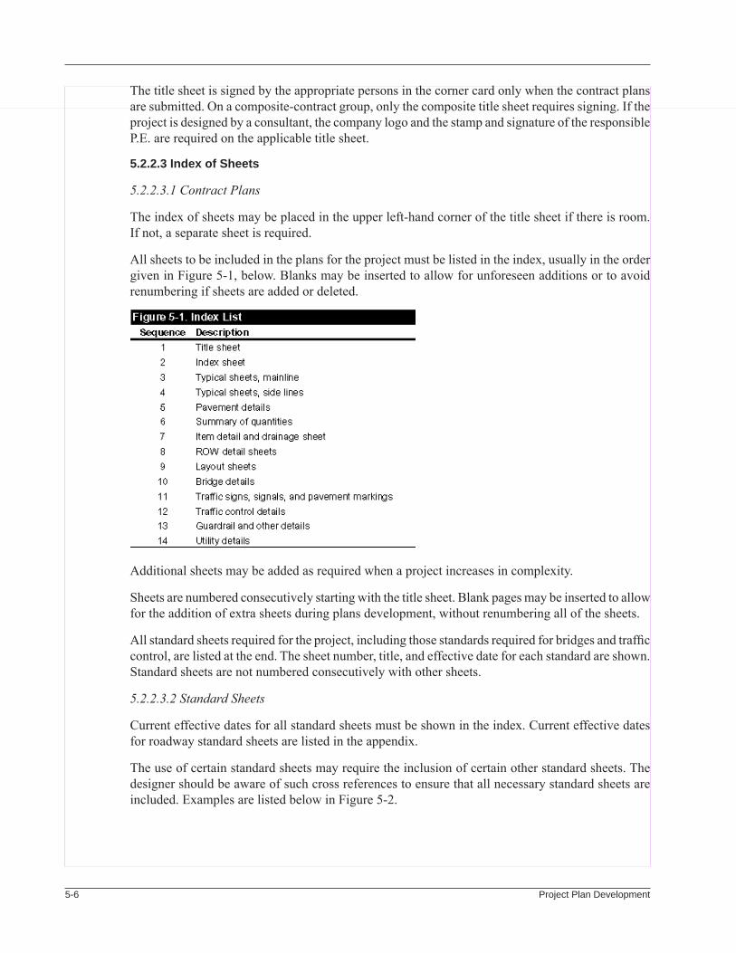
5-� Project Plan Development
The title sheet is signed by the appropriate persons in the corner card only when the contract plans are submitted. On a composite-contract group, only the composite title sheet requires signing. If the project is designed by a consultant, the company logo and the stamp and signature of the responsible P.E. are required on the applicable title sheet.
5.2.2.3 index of sheets
5.2.2.3.1 Contract Plans
The index of sheets may be placed in the upper left-hand corner of the title sheet if there is room. If not, a separate sheet is required.
All sheets to be included in the plans for the project must be listed in the index, usually in the order given in Figure 5-1, below. Blanks may be inserted to allow for unforeseen additions or to avoid renumbering if sheets are added or deleted.
Additional sheets may be added as required when a project increases in complexity.
Sheets are numbered consecutively starting with the title sheet. Blank pages may be inserted to allow for the addition of extra sheets during plans development, without renumbering all of the sheets.
All standard sheets required for the project, including those standards required for bridges and traffic control, are listed at the end. The sheet number, title, and effective date for each standard are shown. Standard sheets are not numbered consecutively with other sheets.
5.2.2.3.2 Standard Sheets
Current effective dates for all standard sheets must be shown in the index. Current effective dates for roadway standard sheets are listed in the appendix.
The use of certain standard sheets may require the inclusion of certain other standard sheets. The designer should be aware of such cross references to ensure that all necessary standard sheets are included. Examples are listed below in Figure 5-2.
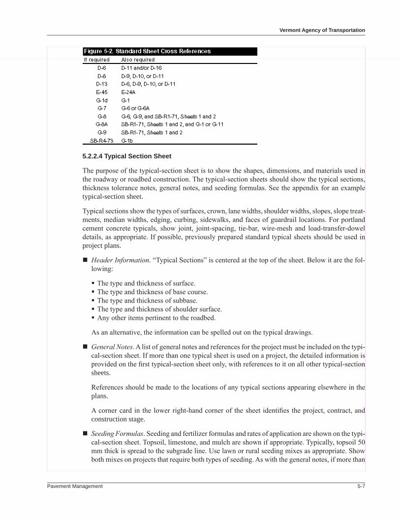
Pavement Management 5-�
Vermont agency of transportation
5.2.2.4 typical section sheet
The purpose of the typical-section sheet is to show the shapes, dimensions, and materials used in the roadway or roadbed construction. The typical-section sheets should show the typical sections, thickness tolerance notes, general notes, and seeding formulas. See the appendix for an example typical-section sheet.
Typical sections show the types of surfaces, crown, lane widths, shoulder widths, slopes, slope treat-ments, median widths, edging, curbing, sidewalks, and faces of guardrail locations. For portland cement concrete typicals, show joint, joint-spacing, tie-bar, wire-mesh and load-transfer-dowel details, as appropriate. If possible, previously prepared standard typical sheets should be used in project plans.
Header Information. “Typical Sections” is centered at the top of the sheet. Below it are the fol-lowing:
The type and thickness of surface. The type and thickness of base course. The type and thickness of subbase. The type and thickness of shoulder surface. Any other items pertinent to the roadbed.
As an alternative, the information can be spelled out on the typical drawings.
General Notes. A list of general notes and references for the project must be included on the typi-cal-section sheet. If more than one typical sheet is used on a project, the detailed information is provided on the first typical-section sheet only, with references to it on all other typical-section sheets.
References should be made to the locations of any typical sections appearing elsewhere in the plans.
A corner card in the lower right-hand corner of the sheet identifies the project, contract, and construction stage.
Seeding Formulas. Seeding and fertilizer formulas and rates of application are shown on the typi-cal-section sheet. Topsoil, limestone, and mulch are shown if appropriate. Typically, topsoil 50 mm thick is spread to the subgrade line. Use lawn or rural seeding mixes as appropriate. Show both mixes on projects that require both types of seeding. As with the general notes, if more than
5-� Project Plan Development
one typical-section sheet is used, the information is provided on only one typical-section sheet.
Other guidance for typical section sheets is below.
Roadway Typicals. Show all of the typicals for the mainline first and then other typicals. Typicals for all driveways and approaches should appear in the project plans. Roadway typical sections must comply with the standard drawings. The use of sections that exceed these must be justi-fied.
Show the number of typical sections needed to define the roadway throughout the project. Each section should show the applicable locations and the widths, thicknesses, and materials as they apply to normal conditions.
Show the number of courses (lifts) and type of mix for each course next to the bituminous con-crete pavement item.
Ditch Typicals. Show detailed drawings of the shoulder composition and ditch dimensions or treatments if required for clarification.
Sidewalks. Follow the standard drawings and AASHTO design standards for typical sections for sidewalks. These standards include ADA ramps. A detail showing pay limits and items should be used when fitting an ADA ramp to an existing sidewalk.
Clear Zones. Clear-zone widths should be specified on all typicals, in fill and cut, except where guardrail is shown. Clear-zone widths should be measured from outside edge of pavement and be based on the criteria discussed in the AASHTO Roadside Design Guide. Typically, the informa-tion is provided only for projects on the NHS.
5.2.2.5 Quantity sheets
The purpose of the quantity sheets is to provide summaries of all bid items for the project. Items are listed in numerical order. The item descriptions must exactly match those carried in the VAOT item listing. Quantity sheets include detailed summaries of quantities for major pay items and summaries of the total estimated quantities for the project. An example quantity sheet is the appendix; it shows the proper notations of the details described below.
Detailed Summary of Quantities. This summary is used to show the breakdown of quantities for major items—large quantities or expensive items. Separate quantities should be shown for each lane (if calculated that way), each ramp, each side line, each rest area, and any special uses. The rounding and total quantity should also be shown.
Each breakdown should be titled with the item name and number. The total should be the project or contract total as it appears in the grand total column on the summary of quantities.
Separate columns are used for quantity sheets that combine projects for letting as a single con-tract.
Summary of Quantities. In this summary, each item used is listed in numerical order by pay item number. Entries are double spaced to allow for adding items during plans development. An ad-ditional column should be added to the left of the item numbers for listing the rounding included in the grand total quantity for each item.
A separate quantity column is required for each of the following types of construction.
Pavement Management 5-�
Vermont agency of transportation
Roadway Bridges—each bridge or pair of bridges requires a separate column Nonparticipating items
Other column types may be required on a case-by-case basis.
If two or more projects are combined for letting as a single contract, a separate summary of quan-tities must be prepared for each project, plus a summary of quantities that shows the grand total for all projects. Roundings and detailed breakdowns are not required on this quantity sheet.
5.2.2.6 item Detail and Drainage sheet
Detailed summaries of information on drainage, guardrail, curbs, and sidewalks are shown on this sheet. Totals of the various quantities are used in compiling quantities on the summary of quantities sheet. More than one sheet may be needed if the items are extensive.
An example item-detail-and-drainage sheet, in the appendix, shows the proper notations of the vari-ous details. The example sheet may need to be modified by the designer for a project’s needs.
Drainage Items. All details that pertain to drainage structures should be listed on this portion of the sheet. Quantities listed that are pay items are subtotaled or totaled, as the case may be, on each sheet. The depths of drop inlets are shown from the top of the grate or the seat of the cover to the inside floor of the drop inlet.
Guardrail. The station-to-station location, side of roadway, length, and number of end treatments are shown on the portion of the sheet that is set up for rail items. The total lengths and number of end treatments are shown.
Curbs. List the curbs by type: asphalt, granite, or concrete. Provide stations and locations in the summary.
Sidewalks. Show the widths, stations, and locations of sidewalk.
5.2.2.7 Miscellaneous roadway Details
Special plan sheets are required to provide the necessary information on construction features, such as pavement transitions, lane tapers, gore transitions, intersection details, channelization, supereleva-tion diagrams, railroad crossings, and minor structures, that cannot be clearly detailed on regular layout sheets.
Pavement Transitions. Paving details of variable-width areas, such as intersections, interchanges, channelized areas, turnarounds, rest areas, and ramp terminals, should be included as part of plans preparation. Include such details as widths, thicknesses, slopes, rates of change in slopes, and spot elevations for the various items. Use VAOT standards for width and depth transitions. Details for transitions at the project termini should be included. Pavement Management recom-mends ways to terminate projects on a project-by-project basis.
Lane Tapers. Use AASHTO standards. Use a larger scale for these drawings: 1:100 or 1:200.
Gore Transitions. Use a larger scale for these drawings: 1:100 or 1:200. Details should show baseline information, pavement widths, shoulder transitions, and grade information at critical points. Proposed contours may be developed to clarify difficult grading areas, such as determin-ing drainage flow.
5-�0 Project Plan Development
Intersection Details. Details such as warping and median nose details should be shown on this sheet. Also show the vertical and horizontal geometrics for large curb radii and turning islands. Grading details should be provided for areas not addressed by the typical sections. Use a larger scale for these drawings: 1:100 or 1:200. The sheets are used to coordinate utility and traffic signal pole locations.
Channelization. Special plan detail sheets are necessary for all major areas of channelization. Pertinent information with respect to dimensions, elevations, construction items, and slopes should be shown on plans. Follow AASHTO design standards to establish channelized dimensions.
5.2.2.8 layout sheets
The layout sheets contain general project data, such as construction and drainage details.
Construction. Show the edges of pavement, edges of shoulders, curbs, sidewalks, drives, all drain-age structures, fencing, and other facilities to be constructed, as well as town and city boundar-ies, on the layout sheets. Stationing is plotted along each layout centerline. Except for special situations such as intersection reconfiguration, no physical survey is required for resurfacing. Layout sheets have no horizontal or vertical alignment, and the stationing scale is compressed. All pavement markings and signage are shown on the layout sheets, with reference to another applicable sheet if more detail is required.
Match lines should be used on the layout sheets to reference the matching sheet number. Proposed construction should not extend beyond the match line.
Abbreviations (codes) on plans should be easily recognized. To avoid misinterpretation, abbre-viations should be identified in the VAOT Standard Specifications or on the layout sheet.
Drainage and Ditch Lining Information. All pertinent details of existing and proposed drainage structures and ditches should be shown and noted on the special plan sheet.
Utility Routes. Utility information is secured by the designer and incorporated into the layout sheets. Separate sheets may be needed for larger projects.
Show each construction note on every layout sheet where it is applicable. An attempt should be made to standardize the location of construction notes of various types and keep related construction notes together (for example, guardrail terminals of various types).
Other features of the layout sheet include the following:
ADA Features. Handicap ramps are shown on the plans in accordance with Agency standards.
Railroad Crossings. Railroad crossings are shown on the layout sheets, if appropriate. Separate sheets are necessary to show the construction details.
Permit Conditions. Any areas not to be entered by the contractor must be identified on the layout sheets.
5.2.2.9 utility sheets
Utility sheets are used to present major utility adjustments and relocations on projects. Minor adjust-ments or relocations may be shown on the layout sheets. A tabular format may be used to indicate utility features and treatments.
Pavement Management 5-��
Vermont agency of transportation
5.2.2.10 Traffic Control Sheets
The designer develops traffic control plans on all projects requiring advanced traffic control details over and above typical AOT details. Refer to the VAOT Traffic Manual for preparation of traffic control sheets.
5.2.2.11 signs and lines sheets
All work necessary to include sign plans, standards, quantities, and estimates as part of a roadway contract should be accomplished by the designer. Refer to the VAOT Traffic Manual for preparation of signs-and-lines sheets.
5.2.2.12 standard sheets
Incorporate all of the required standard sheets into the plans. As noted in Section 5.2.2.3.2, certain standard sheets require the inclusion of other standards. Check Section 5.2.2.3.2 to ensure that all necessary standards are included.
Standard sheets are not numbered sequentially with other plan sheets.
5.3 DeVeloPMent of Plans
5.3.1 steps
Three sets of plans are developed in sequence:
Preliminary plans are complete with all details except for standard sheets. They represent about 75 percent of the total development effort.
Final plans represent about 90 percent of the total development effort. They incorporate review comments on the preliminary plans.
Contract plans represent 100 percent of the total development effort. They incorporate changes as the result of railroad and utility agreements, permit conditions, or comments from Contract Administration.
5.3.2 review of Plans
Preliminary plan sets are distributed by the consultant designer to the following for review and comment:
Pavement Management Section Utilities Unit Construction Section Materials and Research Section DTA (district transportation administrator) Traffic Operations Unit Policy and Planning Division Environmental Unit, Technical section FHWA (Interstate projects only) City (Class 1 projects only)
5-�� Project Plan Development
Notification of plan-set distribution is given to:
RPC (Regional Planning Commission). Plans can be reviewed in the DTA office. Bike Pedestrian Coordinator. Plans can be reviewed at Pavement Management. MPO (Metropolitan Planning Organization). Plans can be reviewed in the DTA office.
Use a standard transmittal letter, as shown in the appendix. (The standard letter for receipt of plans is also in the appendix.)
For the review of final plans, the distribution of plans and notifications are the same as those for the review of preliminary plans, except that a set of plans is distributed to Contract Administration by the Pavement Management Section.
The Pavement Management Section serves as the clearinghouse for all comments from plan reviews. The Section collects, consolidates, edits, and summarizes the comments, including its own concerns, and returns the information and a “redlined” set of plans to the designer.
5.4 Pay iteMs
Guidelines for determining pay items include the Agency’s estimating guidelines and “Average Weighted Low Bid Price Guide.” Use the items needed to accomplish the full scope of the project. Special items are allowed; typically, they are closely allied modifications of the guidelines or stan-dard modifications.
Optional and alternate items are allowed. For optional items, the contractor selects the item to use. Examples are different types of sign posts and bridge joints. For alternate items, the Agency selects the alternate to use.
5.5 Cost estiMates
5.5.1 item Quantities
Item quantities are rounded according to the accepted process for rounding.
5.5.2 unit Prices
Unit prices are based on the current agency-wide average unit-price list. Example sheets from a unit-price list are in the appendix. The list provides price ranges, as well as graphs of quantities versus price. Select the price to use based on knowledge of plant and quarry locations, urban conditions, and other relevant factors. Generally, use higher prices for smaller quantities and lower prices for larger quantities.
Use the memorandums issued by Contract Administration for guidance in determining prices for non-bid items, such as price adjustments for asphalt.
5.5.3 estimate format
The desirable estimate format has the items listed by ascending item number. The columns of the desirable format are:
Pavement Management 5-��
Vermont agency of transportation
Item number Item description Unit Quantity Unit price Total price
The “total price” for the items should be summed, 8 percent should be added for contingencies, and 5 percent should be added for construction engineering. In addition, indicate the project length and the cost per unit length on the estimate.
An example format is in the appendix.
5.6 right-of-Way CertifiCates
The right-of-way certificate confirms that the State owns sufficient right-of-way to execute the project. For Class 1 town highway projects, the certificate covers from curb to curb. The certificate is composed by the Section’s Project Design Engineer and is signed by the Director of Construction and Maintenance. It is submitted with the contract plans. Two examples of right-of-way certificates are shown in the appendix: (1) municipality-owned right-of-way on a Class 1 town highway project and (2) State-owned right-of-way on a State project.
5.7 utility agreeMents
The AOT Utilities Unit works with utility companies to determine utility relocation or adjustments needed because of a project. The Section works from a list of projects provided by Pavement Man-agement. There is no need for the consultant to request the Utilities Unit to perform its work for an individual project, although final plans may need to incorporate features covered in agreements.
5.8 CategoriCal exClusions
The consultant prepares the documents for requesting a categorical exclusion (CE) and submits them with the preliminary plans. An example set of documents is in the appendix. The consultant submits the documents to the Environmental Permits Chief in the Technical Services Division. Permits evalu-ates the request and, if in agreement, submits it to the State Historical Preservation Office (SHPO). If SHPO agrees with the request, it rules that the project is exempt, has no effect, or has no adverse effect. If SHPO rules in any of these ways, Permits sends the request to the FHWA for evaluation. The FHWA may agree with a request early in the plans development process but may reevaluate the request if it has expired at the time the consultant submits the contract plans.
5.9 other reQuireMents
5.9.1 salvage
Salvage requirements are determined during the review of final plans. The governing policy, “Dis-position of Salvageable Material,” is included in the appendix, along with the “Memorandum for the Disposal of Salvageable Material” that is used to request input from the DTA.
5-�� Project Plan Development
5.9.2 Field Office
At the preliminary plan submission, the consultant provides the Construction Section with a request for a field office. The request form is in the appendix. The related pay items are included in the final plans.
5.9.3 Contract Duration or Completion Date
At the preliminary plans submission, the consultant requests the Construction Section for a contract duration or completion date. The request form is in the appendix.
5.9.4 Traffic Control
If traffic control needs exceed VAOT standards, a traffic control plan becomes part of the project plans. The traffic control plan is developed by the design consultant and reviewed by Traffic Design. Its necessity is indicated by the Construction Section on the form for requesting a field office. (See Section 5.9.2 above.)
5.9.5 employee training
The project manager contacts the Office of Civil Rights and Labor to identify training require-ments.
5.10 CoorDination reQuireMents
Coordinating the project with DTA programs, other projects, etc., is performed by Pavement Man-agement. (See Section 4.9.)
The project manager works with local governments to coordinate local projects and public events with the Pavement Management project. The coordination decisions are documented in the special provisions.
5.11 ContraCt sPeCial ProVisions
Contract Administration typically identifies the need for special provisions at final plans review and composes and processes them. However, needs may be identified during the reviews of plans. The project manager advises the designer of special provisions that need to be drafted.
Pavement Management 6-�
Chapter SixQuality Assurance
6.1 IntroductIon
The Pavement Management Section strives to provide quality in all aspects of pavement management: program delivery, program formulation, project plans, project construction, and program adminis-tration. Quality in the pavement management program stems from applying quality assurance and quality control to all parts of the Section’s activity. The efforts involve all members of the Section. To be in concert with this goal, it is desirable that all consultant design firms have established some form of QC/QA program.
6.2 SectIon effortS
The Section has a comprehensive and well-coordinated quality assurance program. The Pavement Management Engineer has established policies and procedures that set the tone for the remainder of the Section. Examples of the efforts include:
Program performance standards are in place. Agency management reviews current performance status each year.
Problems are addressed as they emerge. A collaborative effort involving experts in materials, construction, and design addresses needed improvements. Feedback from resident engineers regarding undesirable features of a paving project helps identify problems.
New and improved materials and techniques result from consulting with engineering firms and attending specialty conferences.
Information and education efforts target a wide variety of people. Legislative leaders and staffs of the Regional Planning Commissions (RPCs) receive briefings to make them aware of Sec-tion goals, intentions, and constraints. Each year, resident engineers receive briefings on paving program goals, the projects being awarded, and new emphasis areas.
Partnering with the paving industry—
A “paving summit” with producers and contractors each December reviews the program for the next paving season. Representatives from the Agency’s Construction and Materials units attend the meeting.

6-� Quality Assurance
Several meetings each year with the Paving Association of Vermont (PAV) review materials specifications and seek improvements in the performance of the paving products.
Cooperative trial installations use new materials and techniques.
Getting the most value for an expenditure—
Compare the proposed cost to design a project with earlier costs for similar projects before authorizing a consultant to proceed. A computer spreadsheet application aids in monitoring design costs. The spreadsheet contains data from several sources to provide considerable in-formation on the project as well as the design contract. A copy of the spreadsheet is available to the Agency’s audit unit for reference in auditing the costs claimed. An example consultant payment spreadsheet is in the appendix.
The proposed prices on contractor bids are scrutinized to ensure that they are comparable to those estimated by the designer and that, if a difference is observed, it is reasonable in light of project conditions.
6.3 ProgrAm QuAlIty
The goal of Program Development is to produce programs of projects that use available funds to the best advantage. Some examples of steps taken toward this goal are:
The pavement management program is fully integrated, encompassing preventive maintenance and resurfacing or rehabilitation of pavement on the network.
Coordination with Agency program managers is continual, with the goal of avoiding conflicting work programs. The Section database (dROAD) contains information on the planned activities in other programs.
Program information regularly goes to each district transportation administrator (DTA). Coordina-tion with the DTAs is continual on their planned bridge, guardrail, culvert, and ditching work.
Coordination with local government is continual to avoid surprises and ensure that there is the maximum amount of coordinated work by both parties. Examples include utility improvements, sidewalk enhancements, and street reconstruction.
Coordination with outside organizations is very active to ensure that their views are known and recognized in the Section’s program. Strong emphasis is placed on hearing from the Agency DTAs and the staffs at the RPCs.
High-quality condition data and state-of-the-art analysis techniques are combined to select the appropriate treatment and location.
Reaction from the Construction Section and Project Design regarding project scope is encour-aged.
6.4 deSIgn QuAlIty
The goal of Project Design is to produce contract plans that are clear and that reflect Section policy. Steps taken to support this goal include:
Pavement Management 6-�
Vermont Agency of transportation
Design guidelines provide direction to the consultant design firms. An example set of plans pro-vides guidance on preferred practice. A program kickoff meeting is held involving all selected design firms to ensure that all receive up-to-date guidance on policy and quality expectations.
A “seed file” for computer-aided design and drafting (CADD) is provided to the design firms so that plans have a consistent layout.
Project Design reviews design work at the preliminary plans stage. It consolidates comments made by other Agency units. Municipal officials may review the plans for projects on Class 1 town highways. One representative plan set from each consultant’s annual output receives a detailed review.
As time allows, Project Design conducts a field review of the plans and project area before completion of design.
Feedback is encouraged from the Construction Section during regional training sessions and during construction, especially from the Section’s Paving Engineer.
Designs specify SHRP climate-specific binders and incorporate the mix design features of Su-perpave.
A design exception requires a sign-off by the Pavement Management Engineer and the Divi-sion Director. Consultant designers must submit design exceptions along with preliminary plan submittals. See the example request in the appendix.
Annual performance evaluations are made of consultants under contract. Evaluations go to the Contract Administration Section. An example evaluation is in the appendix
Design consultants are encouraged to annually submit their evaluation of Section performance.
6.5 conStructIon QuAlIty
Much of the lifetime performance of a pavement depends on the practices and materials used in the course of construction. Steps and measures employed by the Section to secure the best possible quality include:
A bonus-deduct provision for the price bid for mix included in the construction specification is based on ride quality surveys, by the condition survey unit, made on the wearing surface of each newly completed project.
A bonus-deduct provision for the price bid for mix, based on compaction for Marshall designs, is aimed toward obtaining optimum performance from the pavement.
A bonus-deduct provision for the price bid for mix, based on the air voids in the compacted mix, is similarly aimed at obtaining optimum performance.
These quality control/quality acceptance specifications are based on Superpave. The contractor is responsible for testing to confirm all quality features, including field tests for compaction, in accordance with guidelines in the specifications. The Agency’s resident engineer specifies random locations for the field tests.

6-� Quality Assurance
Construction-related problems, such as rapidly deteriorating construction joints, get high-priority attention. Improved techniques are developed in conjunction with the paving industry.
The resident engineer issues change orders to deal immediately with design oversights and “lapses.” The Section fosters a strong, supportive relationship with the project resident engineers by providing quick response to questions and going to field locations if warranted by significant problems related to design oversights.
The Section supports the Pavement Life Study by the Agency’s Research unit. In addition, the Pavement Management Engineer and other individual staff members informally track the per-formance of certain projects that involve trial materials or techniques.
6.6 ProgrAm oVerSIght
The FHWA makes periodic reviews of the Agency’s pavement management activities and the Section’s administration of the program. The normal FHWA focus is on the performance of the Sec-tion under the FHWA/Agency Stewardship Agreement and the Certification Acceptance Agreement. The Certification Acceptance Agreement effectively extends the Stewardship Agreement to those National Highway System (NHS) projects costing more than $1 million, except for major bridge projects. Under these agreements, the Agency conducts all project-related activities in accordance with Agency and FHWA policies, regulations, and procedures.
The concurrence of FHWA is necessary on the plans, specifications, and estimates for all Interstate highway projects and major bridge projects on the NHS. Any design exceptions on these projects require approval by FHWA.
The Director of the Construction and Maintenance Division makes periodic reviews of the status of program development and project design activities. The primary interest is seeing that the activi-ties take place on schedule. The Director’s interest also includes administrative activities, such as performance evaluations, budget preparation and current status, and strategic planning.
Pavement Management 7-�
Chapter SevenContract Plans
7.1 introduCtion
Turning a designer’s vision into work on the roadway requires careful preparation, both during the design phase and in preparation for the bid process. The contractor must be fully and completely aware of the detailed requirements of the project. The Pavement Management Section accomplishes this by presenting clear and detailed plans, with accompanying information, to allow complete specifications.
The public bid process applies to virtually all projects supported by the Pavement Management Section. The work goes to the responsible bidder who proposes the lowest total cost.
7.2 ComPosite ProjeCts
Two to four projects are frequently “bundled” into one contract. The objective is to provide a contract of meaningful dollar value and to provide opportunity for cost economy. Bundling also reduces the amount of administrative work during the bid-and-award phase.
Guidelines on bundling are straightforward:
The projects should be in the same geographic area.
The projects should be in the area supervised by one regional construction engineer.
Class 1 town highway projects are typically not included with State highway or Interstate work, although a contract for work in any one city or village may have more than one project.
7.3 ComPosite Plan set
The set of plans for a composite project has a standard arrangement of pages. A typical plan set includes the following:
Composite title sheet Composite index of sheets Composite quantity sheet(s)
7-� Contract Plans
Project title sheet(s) Project typical sheet(s) Project detail sheet(s) Project quantity sheet(s) Project item detail summary sheet(s) Project layout sheet(s) Projecttrafficsignsummarysheet(s) Project sign detail sheet(s) Project bridge quantity sheet Project bridge detail sheet(s) Construction approach signing sheets Agency standard sheets (as applicable and included by VAOT)
The latest approved Agency standard sheet must be used to avoid delays at this stage of project delivery.
The sample plan set in the appendix contains examples of the following sheets.
7.3.1 Composite title sheet
The title sheet contains information that describes the location and scope of the work. Project loca-tion is described by narrative and by reference to a statewide map and also is shown on a large-scale line drawing.
The edition of the Standard Specifications under which the project was designed is mandatory in-formation. This information is contained in the corner block in standard text for all projects.
The title sheet may contain the index of sheets for the set of project plans if the plans apply to a single project. If there are multiple projects in one contract, the index for the set of contract plans may be on a separate sheet.
The authorizing Agency director must sign the title sheet. If the project was designed by a consult-ingfirm,thetitlesheetmusthavetheprofessionalengineer’sstampandthesignatureofaprincipalinthefirm.Afull-sizeMylarsheetwiththeappropriatestampandsignaturegoestothedirectorfor signature.
7.3.2 Composite index of sheets
If it is not on the title sheet, a separate sheet contains the list of all sheets required to do the work on the project. List each separately titled sheet and its assigned sheet number. Those sheets with the same title or category may be listed with one title and a range of sheet numbers.
If a contract includes more than one project, all the contract sheets are numbered sequentially, with “blanks” left between the individual projects. Random “blanks” are left within the individual projects asthedesignerseesfit.
7.3.3 Composite Quantity summary
The composite quantity summary is a list of all pay items and both the estimated and designed quantities required to complete the work on the contract.
A pay-item description (title) must agree exactly with the description in the Standard Specifica-tions, Supplemental Specifications, or General Special Provisions.Apayitemmustbe“modified”
Pavement Management 7-�
Vermont agency of transportation
if its application in the project is different from that in the Standard Specifications, Supplemental Specifications or General Special Provisions.Ifanitemismodified,itsdescriptionisfollowedbythe indicator “(Mod).” Designers should consult with the design management unit if a pay item cannot be found for work required.
Separate columns contain the pay quantities for all items applicable to the roadway, bridges, non-participating work, or other categories as needed.
If there is more than one project in a contract, pay quantities for each project are shown separately, along with the total pay quantity for the contract. Individual project numbers are the column headers, and there is a “grand total” header for the composite column. The designer must ensure that the indi-vidual project sheets and the composite sheet are consistent in terms of work items and quantities.
A summary breakdown of quantities, required only on the individual project quantity sheets, indicates where the design contemplates use of pay items. For example, bituminous concrete may be called for on drives, side roads, and main line (broken into leveling and wearing course, with applicable grades). Show the estimated quantity for each use.
A two-percent upward rounding is typically applied to quantities estimated as volumes. Show the rounding on the item detail. Unit pay items receive no rounding.
7.4 ContraCt estimate
The designer prepares a cost estimate for each project. The estimate and the project quantity sheet must be consistent. The format for the estimate is: item number, item description, unit of measure-ment, estimated amount (quantity), estimated unit price, and item estimated cost. The cost estimate is in the categories of roadway, bridge, and contingency (10 percent), as well as nonparticipating items. If a project is part of a composite contract, estimates are required for each individual project.
The designer should use the estimated unit price listed in the current Agency Average Weighted Low Bid Price Guide. The estimated price may vary from the Price Guide if the designer has reason to believe that project prices may vary. The designer must justify the use of prices that vary from the Price Guide by presenting a rationale for each item.
Project Design prepares an estimate for the contract from the project estimates and the quantity sheets using the HighEst software. Refer to the manual provided with the HighEst software for details on its use. An example HighEst estimate is in the appendix.
Once the contract estimate is prepared, Project Design updates Screens 34 and 444, Activity 450, in the Preconstruction Project Management System (PPMS). Advise the Pavement Management Engineer and the Pavement Design Engineer of the estimate amount by e-mail.
7.5 reQuired doCuments
The designer must submit a complete package to the Project Design Unit:
A complete “contract” set of full-size project prints, not including the standard drawings refer-enced. The full-size set is accompanied by a half-size hard copy set of reference plans.
An original Mylar title sheet that has a professional engineer’s stamp and is signed by the engi-neer.
7-� Contract Plans
The project cost estimate (one copy).
The design computations (one copy).
Projectplansinelectronicform.ThesefilesareinMicrostationformat,“zipped”(compressed),and placed on diskettes. Refer to the CADD guidelines for paving plans in the appendix.
Explanation of any project special provisions required to clarify the work on the project. For instance, explain “Mod” items that supplement the Standard Specifications, Supplemental Speci-fications, or General Special Provisions.
A memo signed by the Division Director stating that the project can be constructed within the currently controlled rights-of-way. This applies only to a project on a Class 1 town highway.
A memo from the Agency’s Utilities Section identifying any affected utilities. The memo must state that the project can be constructed without interfering with any utilities; if there is potential forconflict,anagreementorconditionsondoingtheworkmustbeattached.Mostoftenthisdocumentation is provided directly to the Contract Administration Section by the Utilities Sec-tion, based on a request submitted with the preliminary plans.
If there is a railroad grade crossing within the project limits, a memo from the Agency’s Rail, Air, and Public Transit Division (RAPT) identifying the railroad operating company and the appropriate contact person. The memo must state the scope of any work near the railroad line. Request the information when submitting the preliminary plans. Attach the agreement signed by the railroad to the memo.
The Agency’s Contract Administration Section (C-A) negotiates the formal agreement with the railroad during the design phase, based on information provided by the RAPT Division. The agreement describes the crossing work and any project-related activities by the contractor. The C-A Section provides the agreement to the Project Design Unit.
A categorical exclusion document (CE) relative to environmental impacts from the project. The document is secured through the Agency’s environmental permits unit. The CE is typically based on investigations done by the consultant designer.
A salvaged materials form in which the appropriate Agency district transportation administra-tor(DTA)orotherAgencyofficialhasindicateddesirestoretainanyoftheremovedmaterials.The form is provided to the DTA with the preliminary plans review set. The DTA forwards the completed form to the Project Design Unit, which forwards it to the designer. The form indicates the materials requested and the locations to which they are to be delivered. Refer to the appendix for the Agency policy on salvage of materials.
Afieldofficerequirementsandestimatedprojectcompletiondateform.Thisformisprovidedto the Construction Engineer with the preliminary plans review set. The Construction Engineer forwards the completed form to the Project Design Unit, which forwards it to the designer.
Examples of the memos and forms mentioned above are in the appendix.
7.6 doCument ProCessing
The Project Design Unit processes and takes administrative actions with respect to the documents received from the designer. This is in preparation for processing of the contract in the Agency’s
Pavement Management 7-�
Vermont agency of transportation
Contract Administration Section.
The “zipped” diskettes containing the project plans are loaded into the Agency’s computer-aided design and drafting (CADD) system. Refer to CADD guidelines for detailed information on loadingandnamingthefile.
A work request transmittal form goes to the Agency Reprographics Unit by way of Groupwise, the Agency’s internal e-mail system. The transmittal form’s subject is “Request for Prints.” The transmittalformcontainsthefilenameandinformstheReprographicsUnitofthedirectorywheretheprojectplansmaybefound.Forexample,iftheprojectPPMSnumberis“95D486,”thefiletitle is pd486_cp.com.ThefileistransmittedtotheAgencyReprographicsUnitwiththepath@isrv02\pave\95d486\pd486_cp.com. Refer to the appendix for an example form.
Review the prints to ensure that CADD standards are appropriate. If satisfactory, the plans are retainedinareferencefile.
The HighEst contract estimate is assembled and submitted to Agency C-A at server isrv01 with a cover sheet. Transmit the estimate with the path @isrv01\autoserv\userdisc\contract\common \estimate.AmemobywayofGroupwisetotheC-AContractandSpecificationsEngineeradvisesthat a completed estimate has been submitted.
Using the HighEst estimate, a TRNSPORT estimate is prepared by C-A and forwarded to the design management unit for later use. Refer to the appendix for examples of HighEst and TRN-SPORT estimates.
7.7 transmittal
The Project Design Unit sends a package of documents to the C-A Section for processing before awarding the contract for the work. Hand-carry the package when all information is available and the Pavement Design Engineer indicates that funding is available.
The documents package consists of:
A project submittal memo requesting advertising of the project, signed by the Pavement Design Engineer. An example memo is in the appendix.
The signed original Mylar title sheet and one copy of the Reprographics-produced plans, not including standard drawings.
Two copies of the TRNSPORT estimate. This is considered to be the engineer’s estimate.
AprojectfinancingmemosignedbythePavementManagementEngineer.Tothisattachasignedform CA-52, a copy of the paving map from the last annual Paving Program Report indicating the project location and the applicable page from the Agency’s Capital Program that contains the funding for the project. An example memorandum and CA-52 are in the appendix.
The ROW-clear memo.
The utility-clear memo and agreement.
The categorical exclusion (CE) document.
The railroad memo and agreement, if applicable.
7-� Contract Plans
The salvaged materials form.
Thefield-office-requirementsform.
The contract completion or duration form. The form establishes requirements for completion. A special provision is written by Contract Administration during contract processing to state a required contract completion date. If the date is not met, the Agency imposes liquidated damages per the Standard Specifications.
Special provisions required for the contract. For example, explanation of any “Mod.” pay items.
All of the documents mentioned above are copied, and a “contract package” is placed in the project design folder for reference purposes during the construction phase. The folder goes to Construction Section at the time the project is advertised for construction bids. Following the construction phase andprojectfinals,thefoldergoestoCentralFiles.
7.8 ContraCt ProCessing
7.8.1 general
The Agency’s Contract Administration Section (C-A) has extensive procedures for placing the work in the hands of a contractor. This manual is not intended to be a full description of the C-A process. Only those portions of the C-A process that affect the Pavement Management Section or are needed to understand the process are described here.
TheC-AContractandSpecificationsEngineer,whoheadstheConstructionContractingunit,re-views the contract package as received from the Project Design Unit. The presence of all required documentsandmaterialisconfirmed.
The Construction Contracting unit does a cursory review of the package to assure consistency and ab-sence of gross errors. If the package is in order, the preparation of the contract document begins.
The documentation required for a bid proposal includes:
The set of contract plans, including standard drawings
The proposal document, which becomes a contract for the project when signed by authorized representatives of the Agency and the contractor after contract award
The contract document has several key components:
Boilerplate requirements on labor rates, civil rights, etc.
A full list of the work items and the estimated quantity for each. The contractor proposes and the Agency accepts a set price per unit for each item.
A copy of the applicable Standard Specifications book. The book is provided to the successful bidder.
The current General Special Provisions and any required Supplemental Specifications. These providemodificationsandclarificationsofthe Standard Specifications’ requirements and apply
Pavement Management 7-7
Vermont agency of transportation
to all contracts.
The project (contract) special provisions. These may modify or clarify the requirements of the Standard Specifications, General Special Provisions, or Supplemental Specifications.
A performance bond and a materials-and-equipment bond.
7.8.2 special Provisions
The special provisions prescribe key requirements for the contractor. They may include the contract completion date, restrictions on doing the work, relations with third parties (local government, utili-ties,railroads,Statemaintenancework,orothercontractorsinvolvedinthesamearea),andspecificrequirements for materials and methods related to or required in the work items.
Projectspecialprovisionsarefirstpublishedinfinaldraftform.Theycontain“standard”modifica-tionstotheworkitemscalledforintheplans.ThemodificationsmaybeduetoarequestfromPave-ment Management. They may be suggestions by one of the Agency’s technical units in response to problems perceived or encountered with respect to the Standard Specifications or General Special Provisions.
The C-A Section circulates the draft project special provisions to various Agency units for comment. The Pavement Management Engineer reviews the draft to ensure that the scope of work is clear, restrictionsareproper,andspecificrequirementsareconsistentwiththeintentofthedesigner.TheEngineer may delegate this review work to the Project Design Unit. Any discrepancies noted or suggestions are given to the C-A Section.
7.8.3 Bid Package
After receiving all comments, the C-A Construction Contracting unit completes the special provisions and is ready to assemble the bid package. This package is available to the prospective contractors for review and preparation of the bid proposal.
7.8.4 advertising
The C-A Section prepares a notice of proposal. A copy is sent to the Associated General Contractors of Vermont. It is posted publicly and placed on the State Library System’s electronic bulletin board.
Interested contractors secure the bid package from C-A for use in assessing the project and preparing bids. Questions that the contractors may have are received by the C-A Section. Valid questions hav-ingsignificancetootherprospectivebiddersresultinanaddendumbeingissuedbyC-A.PavementManagement will likely be consulted on the issue.
No questions should be entertained or answered by Pavement Management Section personnel. Any approaches by a contractor are to be referred to the Chief of Contract Administration.
7.8.5 Bids
At the announced time and place, the bids are opened and read in a public forum. Bids are accepted subject to analysis by the Agency.
The bid analysis consists of tabulating the work items and the unit prices to ensure arithmetic ac-
7-� Contract Plans
curacy. The tabulation includes the engineer’s estimated unit prices and the variance from the bid prices. It includes a comparative tabulation of all bidders’ prices. The apparent low bidder is the bid with the lowest total price proposed to do the work.
7.8.6 Bid review
The bid tabulations are forwarded to the Pavement Management Section as the proponent for the contract. The Section’s duty is to analyze the bids and recommend action by the Division Director and the Secretary of Transportation.
The general rule for analysis is to determine whether the low bidder proposes a pricing structure that would be harmful to the Agency. For example, a quantity computation error may result in a large difference in the actual quantity of work. If the contractor’s unit price is unreasonably high, the Agency could suffer a large loss due to the error. This is an “unbalanced bid” and is grounds for disqualifying the bid.
Expect many variations and circumstances in the bids. Each is evaluated, and a sensible recom-mendation is advanced that protects the interests of the public and the Agency.
Acommonsituationisthereceiptofasinglebid.Thisrequiresaspecialanalysis.Thefirstquestionis the relation of the bid total to the engineer’s estimate. The second question is the unbalanced bid issue noted above. If the total is below the engineer’s estimate, a recommendation to award is in order. If the total is above the engineer’s estimate, a careful scrutiny of the unit prices is required. Consult personnel in the Construction Section or the Materials and Research Section for background on project conditions, mixing plant location, etc.
Review the proposed unit prices for reasonableness, in light of the conditions imposed in the con-tract documents or other factors that would suggest that the bid is more reasonable than the prices in the engineer’s estimate.
Assess the likelihood of receiving multiple bids in another award process. Consider the possible effect of the bid having been revealed publicly, relative to another award process.
After considering these and other factors as applicable, the recommendation is made either to accept the single bid or to deny it and rebid. If the project is rebid, it is advantageous to change the scope of the project by even a small degree.
The recommendation form is signed by the Pavement Management Engineer and the Division Di-rector and then forwarded to the Secretary of Transportation.
An example recommendation is in the appendix.
Pavement Management 8-�
Chapter EightConstruction
8.1 General
Construction is the culmination of the system analysis, program development, project design, and contract award processes.
8.2 role DurinG ConstruCtion
During the construction phase, the Pavement Management Engineer has responsibility for control-ling project scope and cost.
During construction, the project resident engineer has the duty, responsibility, and authority to ensure that the work is carried out according to the plans and specifications. In accordance with the contract documents, the Director of Construction and Maintenance has authority to change the plans to ad-dress conditions encountered in the field. The Director delegates the authority, for most situations, to the resident engineer. The Agency’s Construction Engineer, acting through a regional engineer and resident engineer, approves all changes to the plans and specifications.
The Pavement Management Engineer has limited involvement with any routine field changes and their cost implications. Any significant change or cost increase requires concurrence by the Engineer, as the Program Manager, or the Project Design Unit.
8.3 ConstruCtion support
The Pavement Management Section is frequently called on to assist and support the resident engi-neer. This may entail interpreting the intent of the plans, confirming the need for additional work that is not called for on the plans, or reviewing a cost-saving feature that is identified by the resident engineer or contractor. The resident engineer normally contacts the Project Design staff for advice on how to proceed.
8.3.1 added Work
The resident engineer often notes desirable improvements to drainage facilities. For instance, clearing an obstructed ditch may extend the life of the pavement. Additional drop inlets may reduce ponding
8-� Construction
on the surface.
Requests for change in the scope of work may come from adjacent property owners or local gov-ernment officials. Resurfacing of uneven sidewalks is a common request. Occasionally, the request is to install curbing to control drainage. Any change in scope requires approval by the Pavement Management Engineer.
The resident engineer frequently encounters the need to correct problems existing below the pave-ment. For example, a severe frost heave or an obvious subgrade failure may warrant the removal and replacement of the subbase and some subgrade material. Replacement of a failed culvert before resurfacing avoids disturbing a newly placed pavement. Fixes of this sort are obviously well beyond the scope of a paving project. However, it is not good engineering practice to leave a bad situation uncorrected, and the Pavement Management Engineer may approve of changing the project scope to address the situation.
8.3.2 Decision Making
The resident engineer normally seeks advice regarding unusual circumstances. In significant situa-tions, the Project Design staff views the situation in the field and gives advice. More frequently, the resident engineer phones the staff and discusses alternatives. In the most mundane situations, the resident engineer simply proceeds, using experience and judgment.
In only the most costly and controversial situations are the Pavement Management Engineer and the Director of Construction and Maintenance brought into the decision. Initially the resident or regional engineer discusses the situation with the Pavement Design Engineer or the Project Design staff, and they jointly develop a tentative course of action. The Design Engineer goes to the Pavement Management Engineer and obtains concurrence, which is returned to the Construction Section.
The Construction Engineer then presents the Director with a change of design or a supplementary agreement for approval, according to the guidelines established by the Director. The Director pro-vides a copy of the document to the Pavement Management Section.
8.4 ConstruCtion Quality
Construction quality starts with sound specifications and clear plans, based on well-tried policy and practice. The range of personnel contributing to construction quality includes designers, materials specialists, construction personnel, and industry representatives.
Construction Section management observes that ultimate project quality results from a partnering effort involving the resident engineer, the contractor’s project superintendent, and the mixing plant manager.
Reaction to design practice has two primary sources: the impressions of Pavement Management personnel who visit the projects during and after construction and the input of the resident engineers and inspectors.
The Section always sends a representative to the project preconstruction conference and to participate in the final inspection. At the preconstruction conference, the Section’s representative may offer comments or answer questions from the contractor or other personnel involved with the project.
The final inspection provides an opportunity to ensure that the work is in accordance with the design.
Pavement Management 8-�
Vermont agency of transportation
Either the Pavement Design Engineer or the Pavement Management Engineer reviews the work after receiving notice from the resident engineer that the project is ready for inspection.
During the final inspection, the Section’s representative notes the results of any special treatments or design features. The representative frequently holds discussions with Construction Section manage-ment about what might have been done differently.
Section personnel make visits to projects during the course of construction as time and opportunity permit. Observations are useful, both of techniques and immediate construction quality relative to the specifications.
8.5 FeeDbaCk
Personnel in the Construction Section have extensive opportunity to observe both successes and failures. The Construction Paving Engineer sees every project several times during the active work. The materials inspectors and the construction inspectors provide important input. The resident engi-neer is intimately involved in all aspects of the project. Project reports and the memories of all the people involved serve to bring both successes and failures to the attention of management.
Construction personnel actively seek resolutions to problems that they identify. Sometimes, a joint inspection with the contractor’s quality control specialist serves to identify appropriate corrective action or improvements for the future.
Regional construction closeout sessions serve as an annual forum. In these sessions, each project is reviewed to identify what went well and where there were problems. Ideas for solutions to the problems are sought. For example, a topic might be the problems with certain types of paving machines and the curative measures that worked. The Pavement Management Section design staff attends these sessions and brings back ideas for policy and practice.
Ideas that may be implemented through construction specifications are forwarded by the Pavement Management Engineer to the Specifications Committee.
8.6 Cross-traininG
An important means of bringing field issues into the office is the practice of cross-training by loaning Section personnel to be project inspectors. Problems encountered in the field as a result of scope and design practices prompt better solutions when similar circumstances arise on projects under design. A better end product results from use of informed design knowledge.

8-� Construction
Pavement Management 9-�
Chapter NineMaintenance
9.1 General
The effects of weather and traffic loads work to shorten the useful lives of pavements. Maintenance activities serve to extend the useful lives at modest costs compared with resurfacing or reconstruc-tion.
Maintenance responsibilities and programs involve both the Pavement Management Section and the Maintenance districts. The Pavement Management Engineer is responsible for the surfaces on the State highway system. The maintenance program administered by the Pavement Management Section is primarily preventive. The maintenance program administered by the Maintenance district organizations is primarily restorative.
A close working relationship between Pavement Management and Maintenance enables the assets and capabilities of each program to support the needs of the other, with resultant economies.
9.2 Maintenance indicators
The timing and type of maintenance that is needed for a pavement depend on its current and predicted short-term surface condition. The most current condition information is from firsthand observation by maintenance supervisors and Pavement Management’s Program Development Unit.
Surface defects found in asphalt concrete pavement include potholes, edge breakup, cracking, de-pressions, rutting, and roughness. Quality goals indicate that these defects should be repaired.
9.2.1 Potholes
Potholes are a common defect in thin pavement systems. They appear and develop in size and depth quite rapidly under traffic. The Maintenance district’s forces decide when repair is necessary. Pothole repair is restorative maintenance.
9.2.2 edge Breakup
Deterioration occurs at the edge of pavement due to wheel loads and insufficient lateral or vertical support of the pavement. Edge breakup progresses into the traveled way if wheel loads are repeti-
9-� Maintenance
tive. Repair of edge breakup is restorative maintenance.
9.2.3 cracking
Cracks develop and become wider over time, often taking several years to become significant. Inter-vention is desirable to prevent surface water from entering the pavement and subbase materials. In the subbase, the water contributes to deterioration by softening the materials, leading to undesirable surface deflections by wheel loads. In the pavement, water agitated by tire action causes stripping of binder from the aggregate, leading to weakened pavement.
Cracks in the pavement tend to aggravate local deterioration of the pavement surface by allowing sand particles to enter along with water. The particles prevent the crack from closing during warming months. The result is that more water and sand enter, and the crack becomes wider.
Surface water that is intercepted by a crack may freeze just under the pavement, causing “tenting.” This invariably results in additional cracks parallel with the original crack.
Water trapped within the pavement during cold weather freezes and fractures the pavement, which it-self has lost all flexibility. Further water intrusion inevitably causes the development of a pothole.
Once cracks grow to the point that they join or intersect with other cracks, the development of pot-holes and general pavement deterioration is quite rapid.
Filling the cracks to prevent further water intrusion is a preventive maintenance measure that slows pavement deterioration. Filling may be accomplished by sealing (covering) the entire surface or by applying sealing material directly into the crack.
9.2.4 depressions
The deflection in a roadway that is caused by a wheel load does not fully recover when the subbase is soft. Under repeated loading, the deflected area eventually grows to a large depression, possibly 50 mm or more deep and of sizable extent. It is not feasible for maintenance forces to clean snow from the surface, water puddles accumulate, and ride quality is noticeably reduced. Filling with a leveling course is an appropriate temporary restorative measure.
9.2.5 roughness
Roughness is usually caused by movement within the roadway structure, in the pavement, subbase, or subgrade. It generally develops over the course of several years. Shoving of the pavement oc-casionally occurs at intersections where vehicles stop. Corrugations transverse to the wheel path are the primary symptom. Movement in the subgrade may stem from uneven movement caused by frost action, ice lenses, or swelling of clay layers. Smoothing with a leveling course, or grinding smooth and leveling, are appropriate temporary restorative measures.
9.2.6 rutting
Rutting is usually the result of lateral movement, but may be the result of increased compaction of unstable pavement material under slow-moving or static wheel loads. Most often, long-distance rutting is the result of the loss of air voids in the asphalt concrete caused by improper mixing or compaction during the lay-down process or from the use of a soft asphalt. Rutting may also occur as the result of a weak pavement structure and weak subbase that are subjected to high ESALs. Depending on
Pavement Management 9-�
Vermont agency of transportation
the cause, ruts may be leveled (filled), or a mill-and-fill treatment may be necessary.
9.3 Maintenance ProGraMs
The goal of activities classified as maintenance is either to restore the surface to a serviceable condi-tion or extend the life of the pavement. Maintenance activities are classified as routine or preven-tive, and both are included in a pavement maintenance program. The FHWA publication, Pavement Management Effectiveness, FHWA-SA-96-007, is a reference for the development and management of a pavement maintenance program.
9.3.1 routine Maintenance
As noted previously, the focus of the Maintenance district forces is primarily restorative in nature. Restoration work includes filling potholes, repairing pavement edges, smoothing depressions, and occasionally leveling larger areas.
9.3.1.1 Potholes
The Agency uses high-performance patching materials on the premise that they provide a better-than-temporary repair at very little cost if compared with repeated repair work. These products require minimal preparatory work and installation effort, which greatly aids productivity. Funding is provided from the appropriation for maintenance of highways.
9.3.1.2 leveling
Leveling is a short-term maintenance technique designed to fill depressions, smooth rough areas, and fill ruts. The technique is to place a layer of asphalt concrete over the area, tapering it into the existing pavement so that ride quality is regained. Leveling is done by a skid box or a paver, using Type III or Type IV asphalt-concrete hot-mix. A steel-wheeled roller compacts the material.
If large areas are to be leveled, contractor equipment and personnel may augment the district work force.
Funding may be provided by the maintenance or paving appropriation.
9.3.2 Preventive Maintenance
Preventive maintenance is an integral part of the Agency’s pavement management system. The fo-cus of preventive maintenance is on the midterm of a pavement’s expected life, before substantial deterioration has occurred. Applied under these circumstances, successive applications of preventive maintenance extend the life of a pavement for many years.
The FHWA publication FHWA-SA-96-027, Pavement Maintenance Effectiveness: Preventive Main-tenance Treatments, is a good reference and provides a thorough treatment of this topic. Several techniques and approaches to preventive maintenance are presented.
Preventive maintenance projects are managed and funded by the Pavement Management Section. The projects are intended to delay the need for costly resurfacing treatments or frequent restorative work. Contractors normally do them.
It is difficult to estimate exactly how many extra years of life are gained by active preventive main-tenance. The timing of the maintenance, the subsurface conditions, the ESALs, and the quality of
9-� Maintenance
the initial construction all enter into the question. A preventive maintenance program is not fully effective on a roadway with a weak subbase or one subject to frost heaves.
In practical terms, a preventive maintenance program on a typical 100-mm asphalt concrete pavement structure over suitable subbase starts with a crack-fill operation in the third year after its construc-tion. In the eighth year, repeat the crack-fill operation on any newly developed active cracks, repair deteriorated or damaged crack filler, and seal the inactive cracks. Repeat this crack-fill operation and, if the surface is showing signs of binder deterioration, do a full surface seal in the twelfth year. Repeat the crack fill/seal process for as many cycles as needed until rutting or some other defect indicates that resurfacing is necessary.
Preventive maintenance projects fall into two types: crack-filling and surface sealing. Deciding which to use is a function of crack density.
9.3.2.1 Project selection
The need for and type of crack treatment is determined with information that is secured by the automated condition survey, supplemented by observations of the district personnel and Pavement Management’s program development unit. Field review supplements the automated survey to confirm the amount and type of cracking and establish the limits for scheduled work.
Age is a primary indicator for crack filling. Reflective cracks often appear during the first winter following resurfacing. Thermal-induced cracking may appear in new pavements in the second year following construction, depending on the thermo-resiliency of the bituminous binder.
Experience has shown that although cracking occurs during the first or second winter following construction, the width of cracks is not sufficient to warrant treatment until after the third winter. Usually a high proportion of the cracks are 5 mm wide by that time.
The dTIMS pavement management software has the ability to select preventive maintenance projects. Selection is further refined by district and Section employees.
9.3.2.2 crack Filling and sealing
The FHWA publication FHWA-PD-94-084, Asphalt Pavement Repair, Manuals of Practice, SHRP-H-348, contains a detailed methodology for conducting a crack treatment program involving both crack filling and crack sealing. The publication makes a distinction between the two treatments, based on crack activity, but materials and practices are the same.
Crack filling relates to cracks that “work”; that is, they exhibit movement due to seasonal temperature shifts. Crack sealing applies to treatments for the “non-working” cracks. Due to difficulty in decid-ing which cracks “work” and those that do not, the usual practice is to treat any crack as “working” and to provide a crack-filling treatment.
Agency practice is to distinguish between crack sealing/filling and surface sealing based on the extent of cracking. Sealing over the entire surface area with a thin hot-mix asphalt overlay is considered if cracking is so extensive that filling operations will effectively coat over five percent of an area that is 5 meters or more long and 2 meters wide. Frequently, both crack treatments and surface sealing activities may be necessary on a given stretch of roadway.
A reason for this practice is that filler material is considerably more slippery than the usual AC sur-face. This makes for hazardous riding conditions during wet weather for bicyclists and motorcyclists. Another reason is that extensive crack-filling is uneconomical relative to a thin overlay.
Pavement Management 9-�
Vermont agency of transportation
9.3.2.3 special Problems
Asphalt concrete overlays on PCC pavement are particularly susceptible to reflective cracking at the slab joints. Some of the joints in PCC are quite active, and selective crack-filling is frequently needed after the first or second winter following the overlay construction.
The slabs in PCC may “migrate” significantly and create a wide opening along the centerline. This creates a need for special treatment of the opening, usually cleaning accumulated debris and filling with hot mix.
Widening of PCC pavements with an asphalt construction has been practiced on some routes. The widened area may fail prematurely, usually requiring leveling or shimming of the area to raise it to that of the adjacent pavement. This probably will be needed after five to ten years.
Longitudinal cracks or openings at the cold joints in an overlay are a special problem. Early onset of the problem indicates poor compaction in joint areas. Sawing or milling out an area may be nec-essary before replacing it with the original type and depth of overlay material. Sealing the crack is essential if the material is not replaced.
Another special problem is the settlement or shoving of asphalt concrete pavement widening be-cause of truck traffic. Early failures typically result from inadequate base compaction or subbase materials, resulting in cracks at the edge of the original pavement. Remedies range from leveling the widening to reconstructing it.
Rutting in the travel lane of a freeway is a common problem. This may be treated by filling the ruts in lieu of a rehabilitation project. Microsurfacing or Type V asphalt concrete are possible filling materials. In this way, the defect in the travel lane may be corrected, avoiding the necessity of work on the passing lane.
9.3.3 crack Filling
Crack filling is appropriate if a large proportion of the crack length is well developed and the pave-ment adjacent to the crack has not deteriorated. Once cupping (depression adjacent to the crack) or active cracks in the adjacent area have developed, it is too late. Ride quality is severely diminished, stripping may be occurring within the pavement material, and a curative measure is required, rather than a maintenance measure.
There are two essential elements for successful crack-filling:
The crack must be properly prepared. The proper filler material must be used.
Failure to observe both elements invariably leads to failure of this maintenance measure.
Crack filling is most effective on thermal or transverse cracking. Longitudinal joints that result from construction activities benefit from crack filling, while longitudinal cracks resulting from fatigued pavements are generally not good candidates. Cracks that are between 3 mm and 25 mm wide are the best candidates.
Longitudinal cracks or openings, which are related to cold joints in the pavement or other construc-tion-related problems, are treated when they appear. Other longitudinal cracks receive the same attention. Many agencies recommend no attention be given to these cracks, on the premise that they are due to subsurface problems that continue despite maintenance. VAOT practice is to treat these
9-� Maintenance
cracks because to allow water intrusion is to encourage rapid deterioration of the pavement during freeze-thaw cycles. Longitudinal cracks are given proper preparation and then flush-filled with no over-band.
Cracks in open-graded friction-course pavements are a special problem. Transverse cracks may be properly prepared and flush-filled. No longitudinal cracks are to be filled (other than at the high point in a crowned cross-section), because to do so interferes with the internal drainage feature of the open gradation.
9.3.3.1 crack Preparation
Mechanical shaping of a crack is a necessary part of preparation. The mechanical shaping should result in a square reservoir at the surface, 10 mm to 20 mm wide and equally as deep. The crack is then thoroughly cleaned, dried, and heated.
9.3.3.2 Filler Material
The Agency’s standard filler material is a rubberized asphalt. It is hot-applied with a thin and nar-row over-band in most situations. The width of over-band should be limited to 50 mm. The depth of over-band is limited to a thin film of less than 3 mm over the existing pavement. A flush-fill may be used if the uneven surface appearance of over-banding is not acceptable or if there is concern about creating a slippery surface.
9.3.3.3 Material requirements and cost
For preparing programs of projects, use the following estimating factors.
Transverse cracking only: 335 kg per lane-km Moderate cracking in a thin overlay: 420 kg per lane-km General cracking, both transverse and longitudinal: 560 to 700 kg per lane-km Heavy block cracking: 840 kg per lane-km
Productivity is about three lane-km per day per crew.
9.3.3.4 service life
Service life of crack-filling may be as short as two years or as long as seven years. As reported by ERES Consultants, Inc., in a July 1996 publication, Long-term Monitoring of Pavement Maintenance Materials Test Sites, observations made during the SHRP long-term monitoring program found that crack-filling, using the configuration and materials described above, was 75 percent effective after four winters. Failure occurred to a very small degree during the first three years following installation and then accelerated in a typical degradation model. Failure mode was mostly adhesion loss, but only where crack movement exceeded 7 mm at the highest recorded locations. Very similar results have been recorded in Agency research installations.
Repairing failed crack filler is as simple as removing debris with compressed air and then placing new hot-poured material in the opening. Bond is usually very good with preexisting bituminous crack filler.
Excessive crack movement is the primary cause for failure in any crack-filler material. Those cracks that exhibit early failure may need a treatment that provides for greater movement capacity. Improper technique during initial installation of crack filler may also be cause for failure. Removal and instal-lation of new material may be necessary.
Pavement Management 9-�
Vermont agency of transportation
9.3.3.5 Specifications
Item 417, “Bituminous Crack Filling,” is the appropriate pay item.
9.3.4 sealing
Surface sealing has the same objective as crack filling: to prevent or reduce the intrusion of water into the pavement and retard its deterioration.
Sealing is considered if an area has a high density of cracks. If so, a seal is applied to the larger area, covering the full lane or roadway width. If there is a high density of cracks with considerable edge deterioration or depressed areas, sealing provides only a limited gain in pavement life. Rehabilita-tion in the form of an overlay or other substantial treatment is a necessity.
The seal may be a liquid type, such as a chip seal, a sand seal, microsurfacing, or a slurry seal. A fog seal is a potential treatment for open-graded friction-course surfaces. If the liquid type of seals are used, the cracks must be prepared and filled in advance. The more usual and generally preferred seal in the Agency is a thin overlay of hot-mix asphalt concrete. Not only is the surface area sealed, the overlay may also accomplish some degree of leveling. If warranted by roughness or cross-section problems, a localized preliminary leveling course may be applied before sealing.
9.3.4.1 seal Preparation
Preparation for AC sealing consists of flush-filling cracks that are 25 mm or larger and filling depres-sions with pothole repair material or hot-mix asphalt pavement material. Broom any sand or other loose materials off the surface and from the topmost portions of the cracks. Apply asphalt-emulsion tack material over the entire area before placing the seal material, except if a liquid seal is used.
9.3.4.2 seal Materials
The preferred material for a thin overlay is a Type IV asphalt concrete, placed with a depth of 15 mm to 20 mm. Alternatively, a very thin overlay of Type V asphalt concrete, placed with a depth of 10 mm to 15 mm, may be used if no leveling is required.
Alternative seal materials include chip seal, slurry seal, and microsurfacing. Chip seal use is restricted to very low-volume roadways with little bicycle traffic.
9.3.4.3 Specifications
Item 406, “Bituminous Concrete Pavement,” is the appropriate pay item for sealing with a thin overlay. Indicate the necessary preparation in notes on the plans or in special provisions.
9.3.4.4 service life
Service life for a seal is approximately four years for a liquid seal and four to eight years for a thin overlay. It may be more or less because of the subbase and pavement conditions prior to sealing. Some localized lifting of thin overlays may occur, but this does not materially affect the performance of the seal. Reflective cracking through the seal is expected, and crack filling may be required after the third winter of service.

9-� Maintenance

Pavement Management A-�
Appendix Appendix
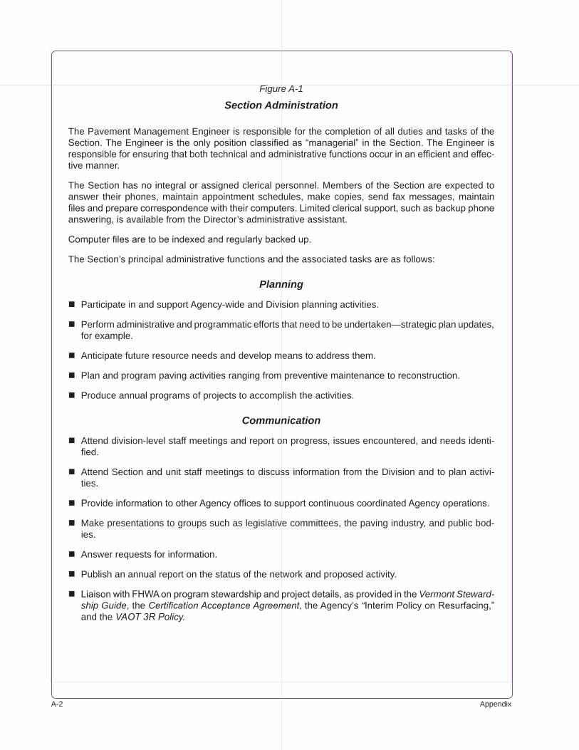
A-� Appendix
Figure A-1
Section Administration
The Pavement Management Engineer is responsible for the completion of all duties and tasks of the Section. The Engineer is the only position classified as “managerial” in the Section. The Engineer is responsible for ensuring that both technical and administrative functions occur in an efficient and effec-tive manner.
The Section has no integral or assigned clerical personnel. Members of the Section are expected to answer their phones, maintain appointment schedules, make copies, send fax messages, maintain files and prepare correspondence with their computers. Limited clerical support, such as backup phone answering, is available from the Director’s administrative assistant.
Computer files are to be indexed and regularly backed up.
The Section’s principal administrative functions and the associated tasks are as follows:
Planning
Participate in and support Agency-wide and Division planning activities.
Perform administrative and programmatic efforts that need to be undertaken—strategic plan updates, for example.
Anticipate future resource needs and develop means to address them.
Plan and program paving activities ranging from preventive maintenance to reconstruction.
Produce annual programs of projects to accomplish the activities.
Communication
Attend division-level staff meetings and report on progress, issues encountered, and needs identi-fied.
Attend Section and unit staff meetings to discuss information from the Division and to plan activi-ties.
Provide information to other Agency offices to support continuous coordinated Agency operations.
Make presentations to groups such as legislative committees, the paving industry, and public bod-ies.
Answer requests for information.
Publish an annual report on the status of the network and proposed activity.
Liaison with FHWA on program stewardship and project details, as provided in the Vermont Steward-ship Guide, the Certification Acceptance Agreement, the Agency’s “Interim Policy on Resurfacing,” and the VAOT 3R Policy.
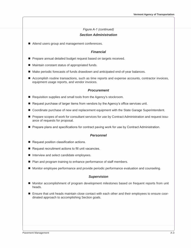
Pavement Management A-�
Vermont Agency of Transportation
Attend users group and management conferences.
Financial
Prepare annual detailed budget request based on targets received.
Maintain constant status of appropriated funds.
Make periodic forecasts of funds drawdown and anticipated end-of-year balances.
Accomplish routine transactions, such as time reports and expense accounts, contractor invoices, equipment usage reports, and vendor invoices.
Procurement
Requisition supplies and small tools from the Agency’s stockroom.
Request purchase of larger items from vendors by the Agency’s office services unit.
Coordinate purchase of new and replacement equipment with the State Garage Superintendent.
Prepare scopes of work for consultant services for use by Contract Administration and request issu-ance of requests for proposal.
Prepare plans and specifications for contract paving work for use by Contract Administration.
Personnel
Request position classification actions.
Request recruitment actions to fill unit vacancies.
Interview and select candidate employees.
Plan and program training to enhance performance of staff members.
Monitor employee performance and provide periodic performance evaluation and counseling.
Supervision
Monitor accomplishment of program development milestones based on frequent reports from unit heads.
Ensure that unit heads maintain close contact with each other and their employees to ensure coor-dinated approach to accomplishing Section goals.
Figure A-1 (continued)
Section Administration
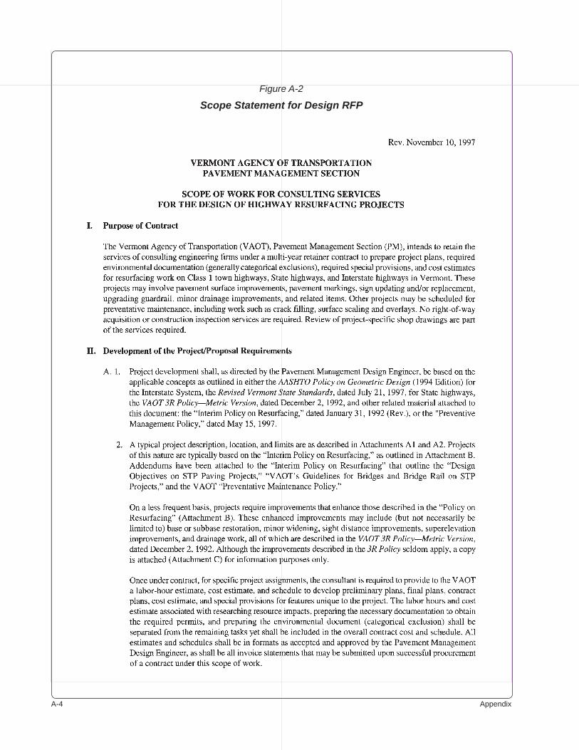
A-� Appendix
Figure A-2
Scope Statement for Design RFP
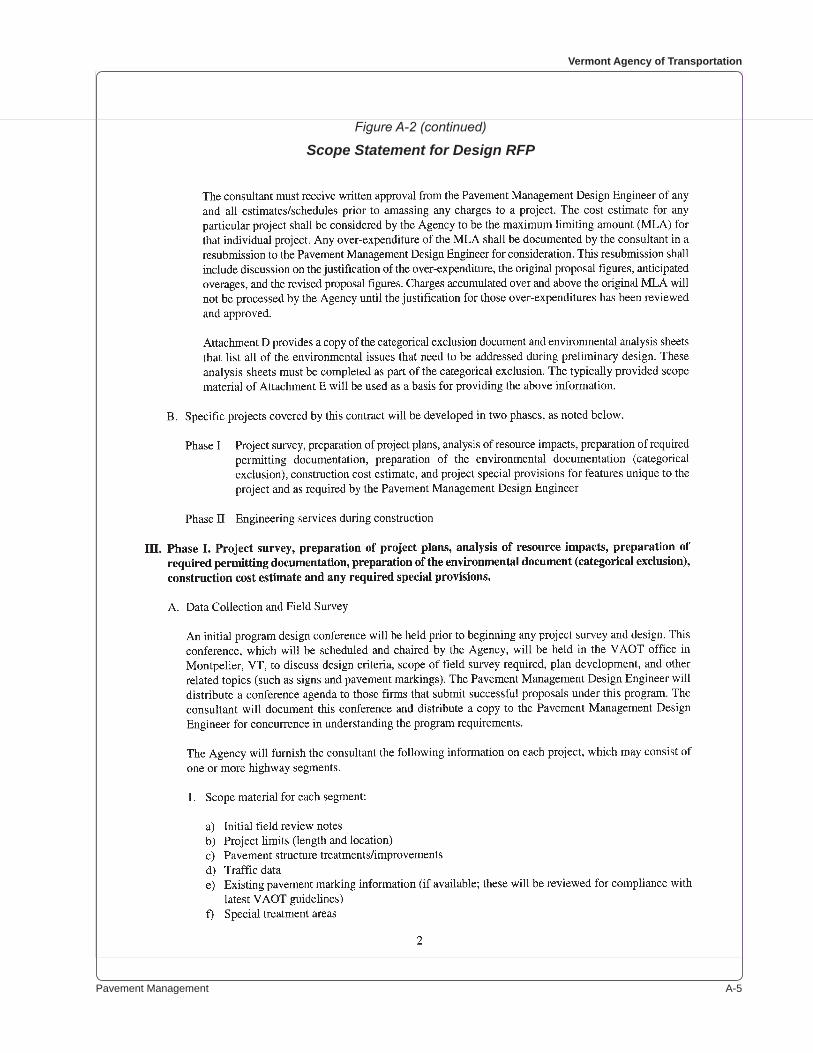
Pavement Management A-�
Vermont Agency of Transportation
Figure A-2 (continued)
Scope Statement for Design RFP
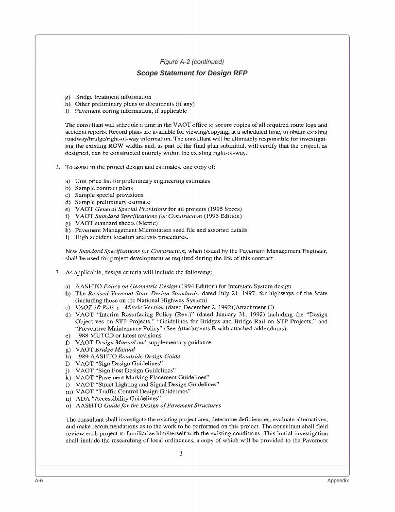
A-� Appendix
Figure A-2 (continued)
Scope Statement for Design RFP
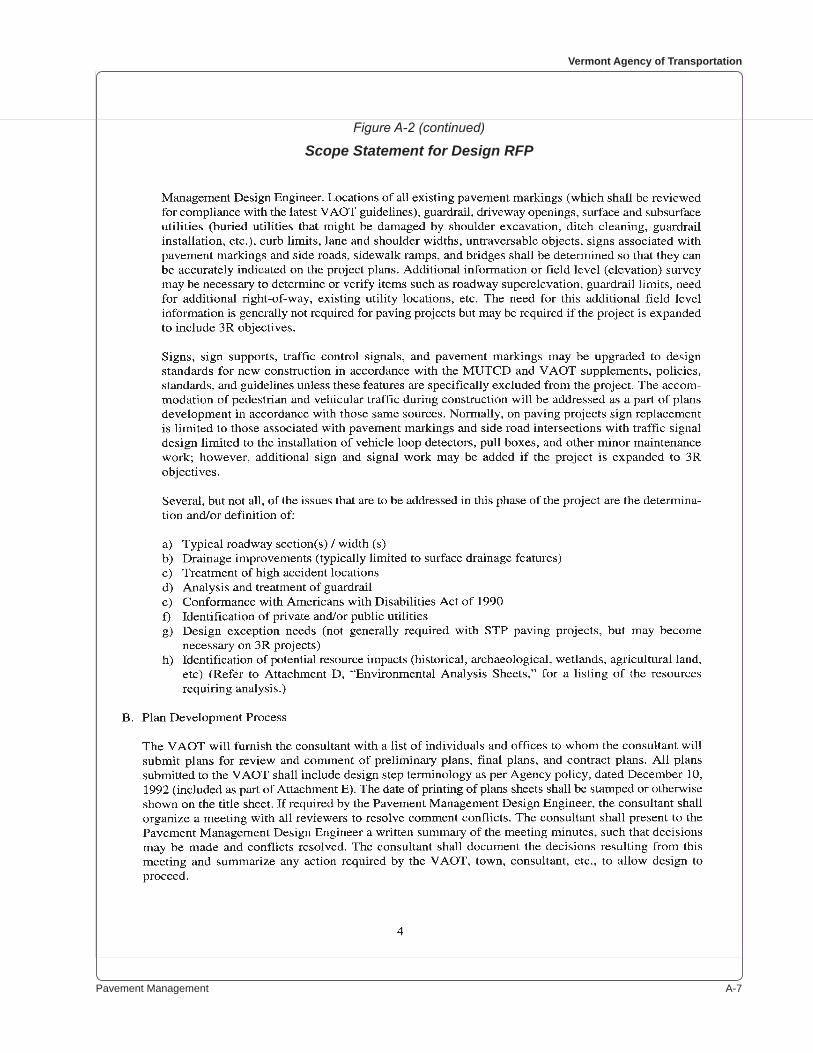
Pavement Management A-�
Vermont Agency of Transportation
Figure A-2 (continued)
Scope Statement for Design RFP
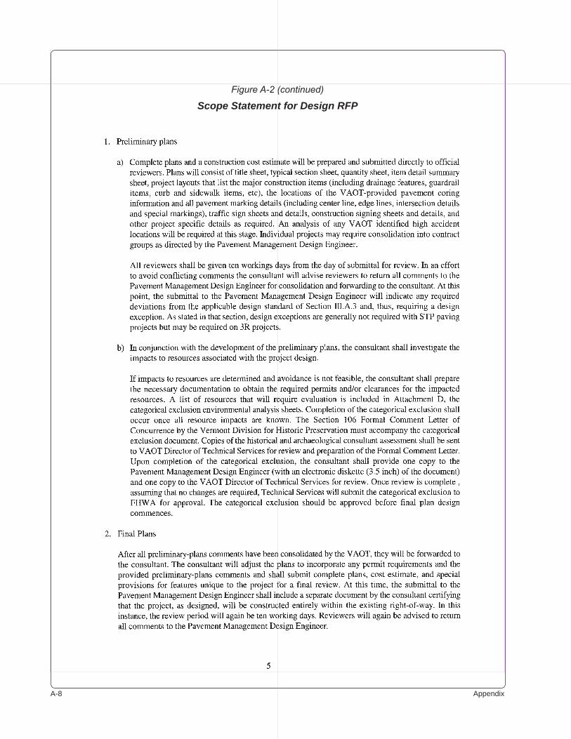
A-� Appendix
Figure A-2 (continued)
Scope Statement for Design RFP
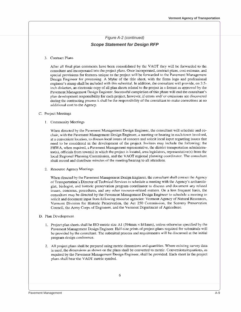
Pavement Management A-�
Vermont Agency of Transportation
Figure A-2 (continued)
Scope Statement for Design RFP
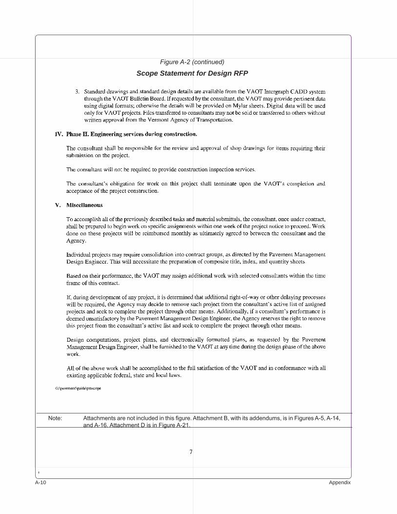
A-�0 Appendix
Figure A-2 (continued)
Scope Statement for Design RFP
Note: Attachments are not included in this figure. Attachment B, with its addendums, is in Figures A-5, A-14, and A-16. Attachment D is in Figure A-21.
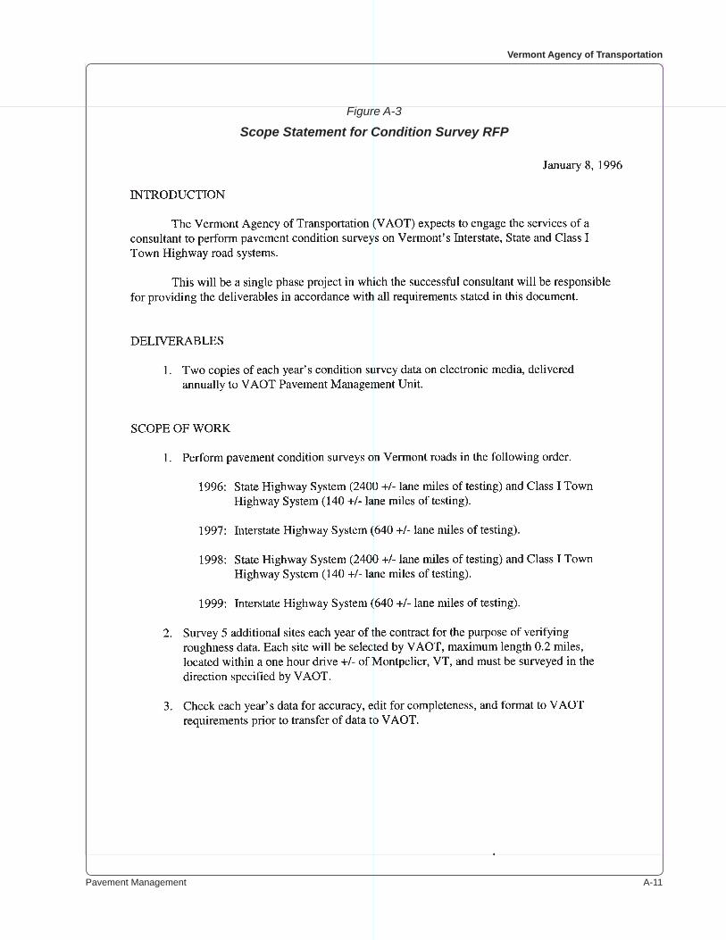
Pavement Management A-��
Vermont Agency of Transportation
Figure A-3
Scope Statement for Condition Survey RFP
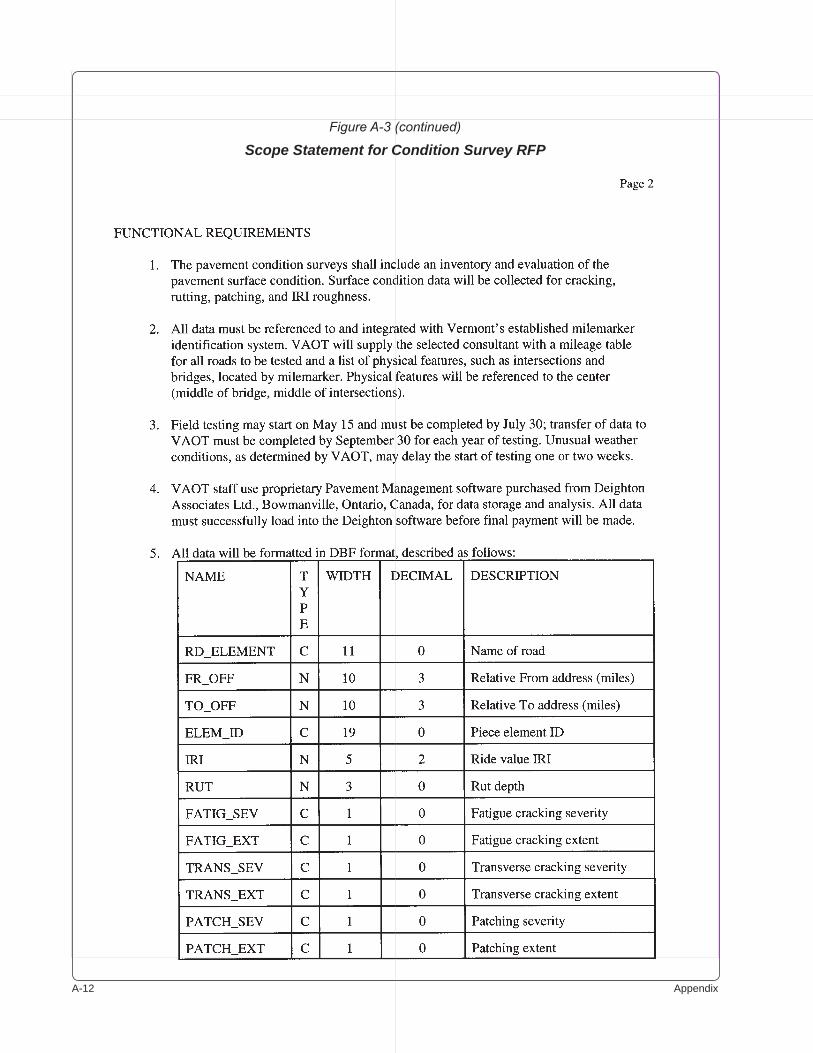
A-�� Appendix
Figure A-3 (continued)
Scope Statement for Condition Survey RFP
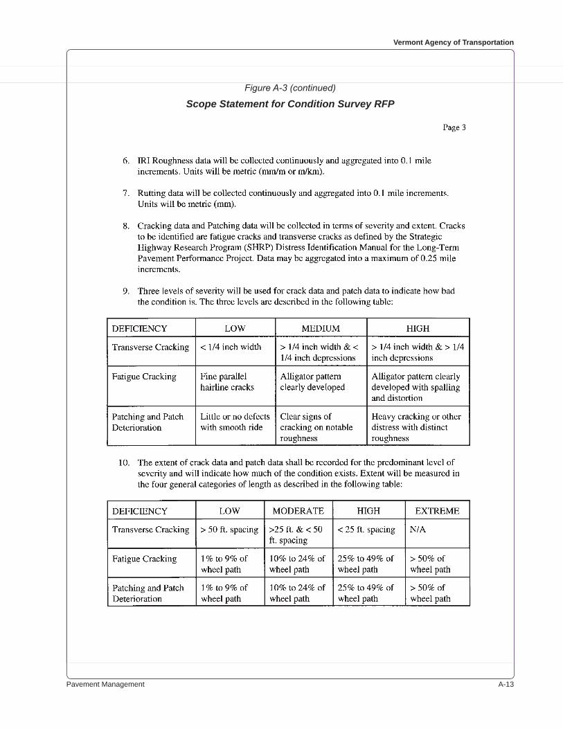
Pavement Management A-��
Vermont Agency of Transportation
Figure A-3 (continued)
Scope Statement for Condition Survey RFP
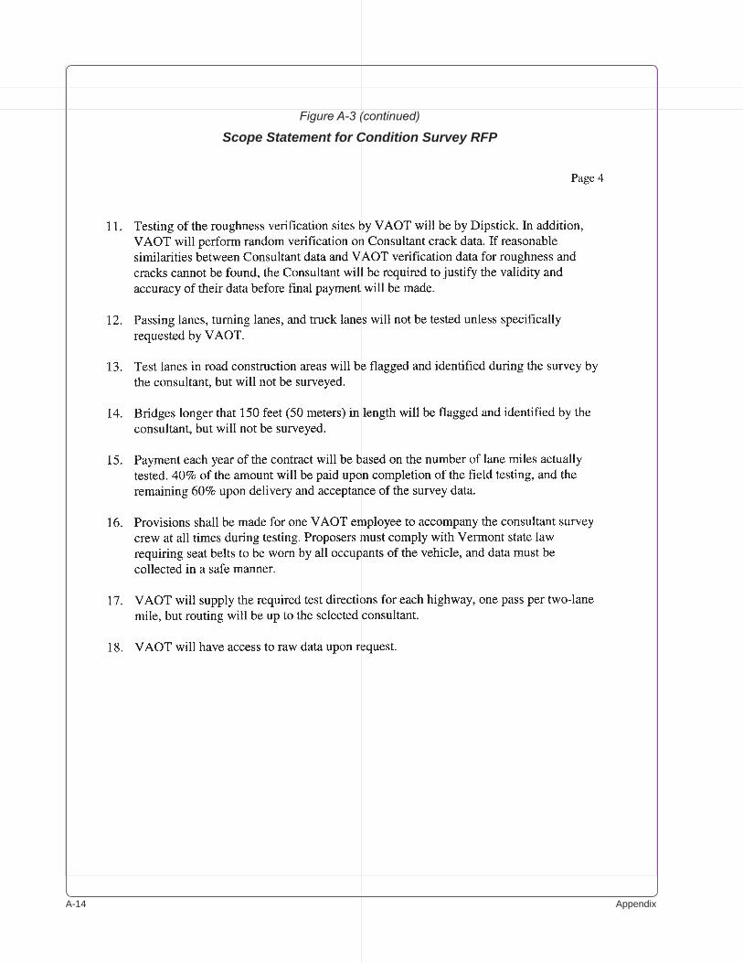
A-�� Appendix
Figure A-3 (continued)
Scope Statement for Condition Survey RFP
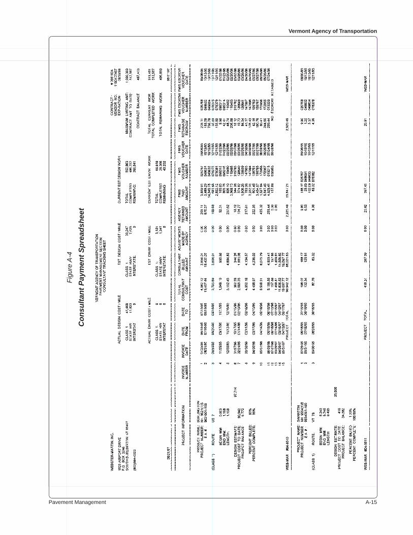
Pavement Management A-��
Vermont Agency of Transportation
Figu
re A
-4
Con
sulta
nt P
aym
ent S
prea
dshe
et
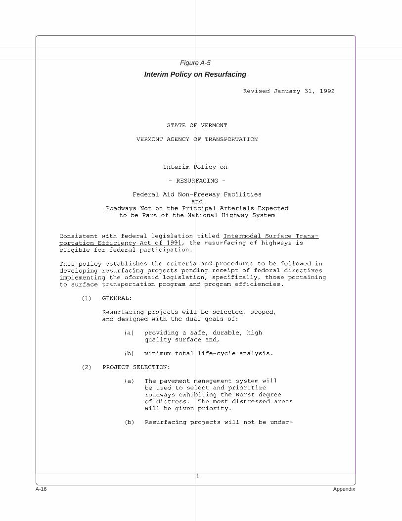
A-�� Appendix
Figure A-5
Interim Policy on Resurfacing
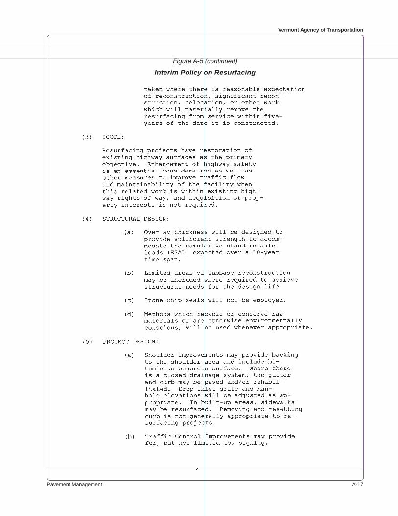
Pavement Management A-��
Vermont Agency of Transportation
Figure A-5 (continued)
Interim Policy on Resurfacing
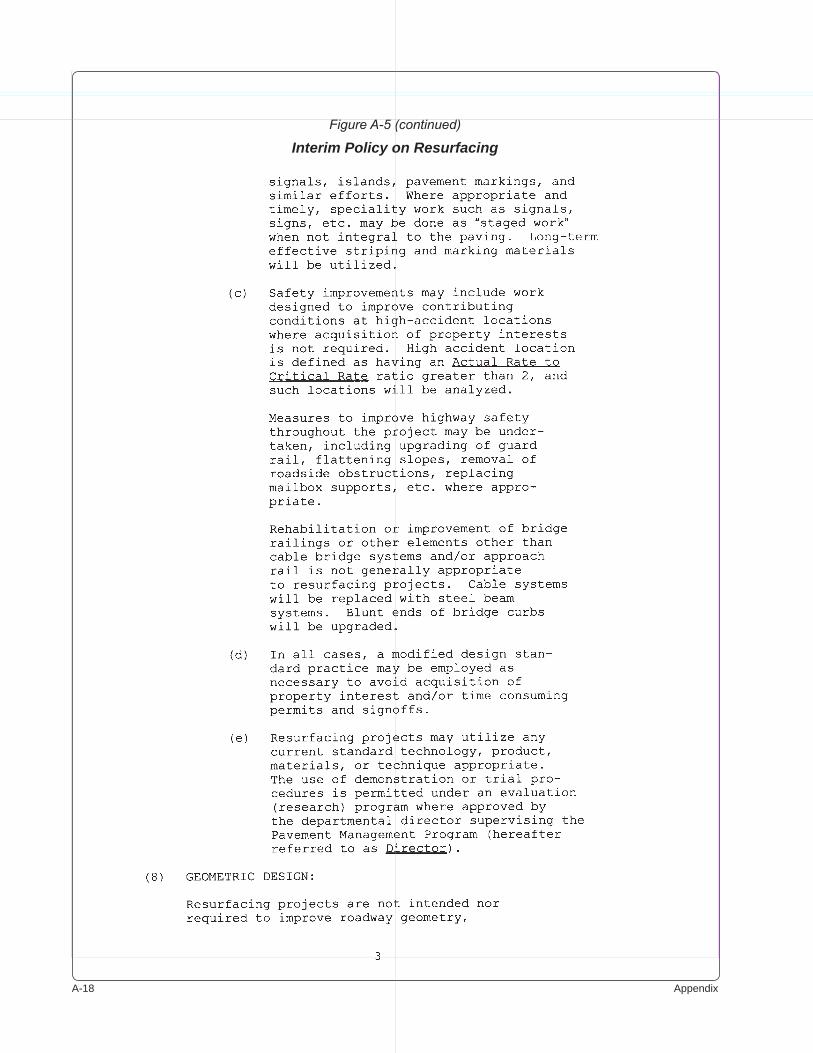
A-�� Appendix
Figure A-5 (continued)
Interim Policy on Resurfacing
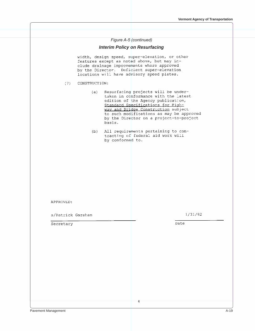
Pavement Management A-��
Vermont Agency of Transportation
Figure A-5 (continued)
Interim Policy on Resurfacing
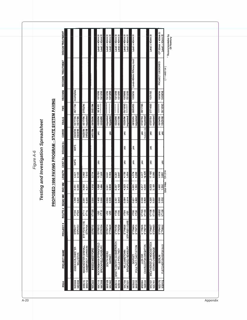
A-�0 Appendix
Figu
re A
-6
Test
ing
and
Inve
stig
atio
n Sp
read
shee
t
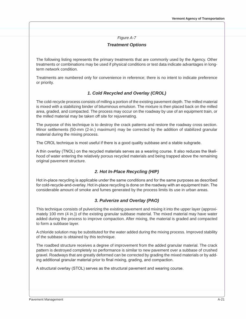
Pavement Management A-��
Vermont Agency of Transportation
Figure A-7
Treatment Options
The following listing represents the primary treatments that are commonly used by the Agency. Other treatments or combinations may be used if physical conditions or test data indicate advantages in long-term network condition.
Treatments are numbered only for convenience in reference; there is no intent to indicate preference or priority.
1. Cold Recycled and Overlay (CROL)
The cold-recycle process consists of milling a portion of the existing pavement depth. The milled material is mixed with a stabilizing binder of bituminous emulsion. The mixture is then placed back on the milled area, graded, and compacted. The process may occur on the roadway by use of an equipment train, or the milled material may be taken off site for rejuvenating.
The purpose of this technique is to destroy the crack patterns and restore the roadway cross section. Minor settlements (�0-mm (�-in.) maximum) may be corrected by the addition of stabilized granular material during the mixing process.
The CROL technique is most useful if there is a good quality subbase and a stable subgrade.
A thin overlay (TNOL) on the recycled materials serves as a wearing course. It also reduces the likeli-hood of water entering the relatively porous recycled materials and being trapped above the remaining original pavement structure.
2. Hot In-Place Recycling (HIP)
Hot in-place recycling is applicable under the same conditions and for the same purposes as described for cold-recycle-and-overlay. Hot in-place recycling is done on the roadway with an equipment train. The considerable amount of smoke and fumes generated by the process limits its use in urban areas.
3. Pulverize and Overlay (PAO)
This technique consists of pulverizing the existing pavement and mixing it into the upper layer (approxi-mately �00 mm (� in.)) of the existing granular subbase material. The mixed material may have water added during the process to improve compaction. After mixing, the material is graded and compacted to form a subbase layer.
A chloride solution may be substituted for the water added during the mixing process. Improved stability of the subbase is obtained by this technique.
The roadbed structure receives a degree of improvement from the added granular material. The crack pattern is destroyed completely so performance is similar to new pavement over a subbase of crushed gravel. Roadways that are greatly deformed can be corrected by grading the mixed materials or by add-ing additional granular material prior to final mixing, grading, and compaction.
A structural overlay (STOL) serves as the structural pavement and wearing course.

A-�� Appendix
4. Mill and Fill (MAF)
Mill-and-fill consists of milling 50 to 80 mm (2 to 3 in.) of existing pavement and replacing it with two lifts of bituminous concrete.
This technique is relatively costly and ordinarily is used only if necessary to preserve or restore curb reveal. It may be used on the driving lanes if paved shoulder areas do not require rehabilitation.
In locations where previous resurfacing has resulted in little or no curb reveal or excessive crown, mill-ing depth is increased.
5. Structural Overlay (STOL)
This technique consists of adding lifts of bituminous concrete to the existing flexible pavement, as nec-essary to provide the designed pavement thickness. The overlay may be preceded by a full or partial leveling course to take out surface irregularities, depending on the amount of deformation present.
Overlays provide added strength to the pavement structure, but they are susceptible to the onset of reflective cracking along the course of cracks in the underlying pavement.
A structural overlay is best used if investigation indicates added pavement structure is needed and before the severity and extent of cracking are rated as high.
6. Level and Overlay (LVOL)
Level-and-overlay consists of applying a bituminous concrete leveling course to bring the low areas in the roadway surface up to normal cross section and to provide minimal cover over the higher points. The leveling may cover one-half of a roadway or its entire width. The overlay is normally one �� mm (��/� in.) thick course of bituminous concrete over the entire roadway.
7. Thin Overlay (TNOL)
This technique consists of placing one course of bituminous material. Usually the material is �0 mm (�/� in.) deep over the highest area of the roadway cross section. Leveling occurs to a limited degree.
This is ordinarily a technique for preventive maintenance. It is applicable when the roadway has good cross-section, but the surface is weathered, and considerable crackfilling or patching of pot holes is necessary.
A high-order variation of this technique uses a coarse-graded, high-percentage asphalt mixture, �0 mm (�/� in.) deep, as the wearing course. The technique results in significantly reduced water spray from tires and a much quieter ride. It is primarily for freeway-type highways. The open-graded friction course has demonstrated exceptionally long life.
Figure A-7 (continued)
Treatment Options
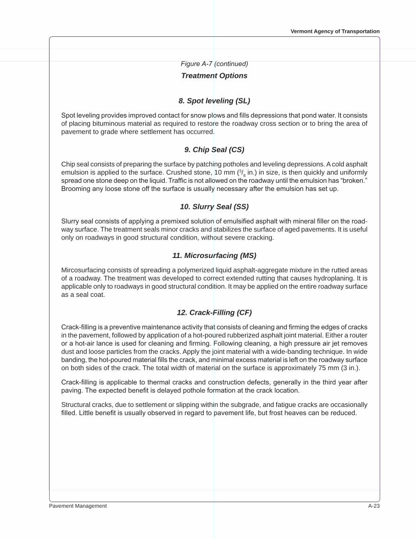
Pavement Management A-��
Vermont Agency of Transportation
8. Spot leveling (SL)
Spot leveling provides improved contact for snow plows and fills depressions that pond water. It consists of placing bituminous material as required to restore the roadway cross section or to bring the area of pavement to grade where settlement has occurred.
9. Chip Seal (CS)
Chip seal consists of preparing the surface by patching potholes and leveling depressions. A cold asphalt emulsion is applied to the surface. Crushed stone, �0 mm (�/� in.) in size, is then quickly and uniformly spread one stone deep on the liquid. Traffic is not allowed on the roadway until the emulsion has “broken.” Brooming any loose stone off the surface is usually necessary after the emulsion has set up.
10. Slurry Seal (SS)
Slurry seal consists of applying a premixed solution of emulsified asphalt with mineral filler on the road-way surface. The treatment seals minor cracks and stabilizes the surface of aged pavements. It is useful only on roadways in good structural condition, without severe cracking.
11. Microsurfacing (MS)
Mircosurfacing consists of spreading a polymerized liquid asphalt-aggregate mixture in the rutted areas of a roadway. The treatment was developed to correct extended rutting that causes hydroplaning. It is applicable only to roadways in good structural condition. It may be applied on the entire roadway surface as a seal coat.
12. Crack-Filling (CF)
Crack-filling is a preventive maintenance activity that consists of cleaning and firming the edges of cracks in the pavement, followed by application of a hot-poured rubberized asphalt joint material. Either a router or a hot-air lance is used for cleaning and firming. Following cleaning, a high pressure air jet removes dust and loose particles from the cracks. Apply the joint material with a wide-banding technique. In wide banding, the hot-poured material fills the crack, and minimal excess material is left on the roadway surface on both sides of the crack. The total width of material on the surface is approximately �� mm (� in.).
Crack-filling is applicable to thermal cracks and construction defects, generally in the third year after paving. The expected benefit is delayed pothole formation at the crack location.
Structural cracks, due to settlement or slipping within the subgrade, and fatigue cracks are occasionally filled. Little benefit is usually observed in regard to pavement life, but frost heaves can be reduced.
Figure A-7 (continued)
Treatment Options
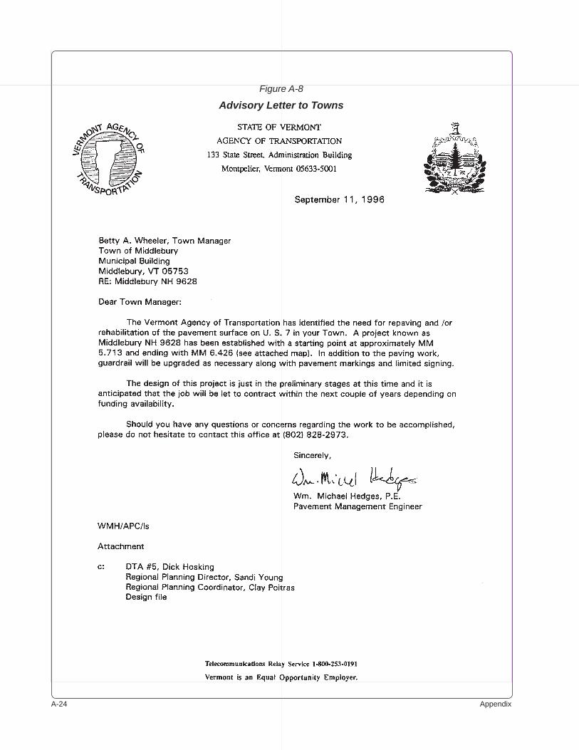
A-�� Appendix
Figure A-8
Advisory Letter to Towns
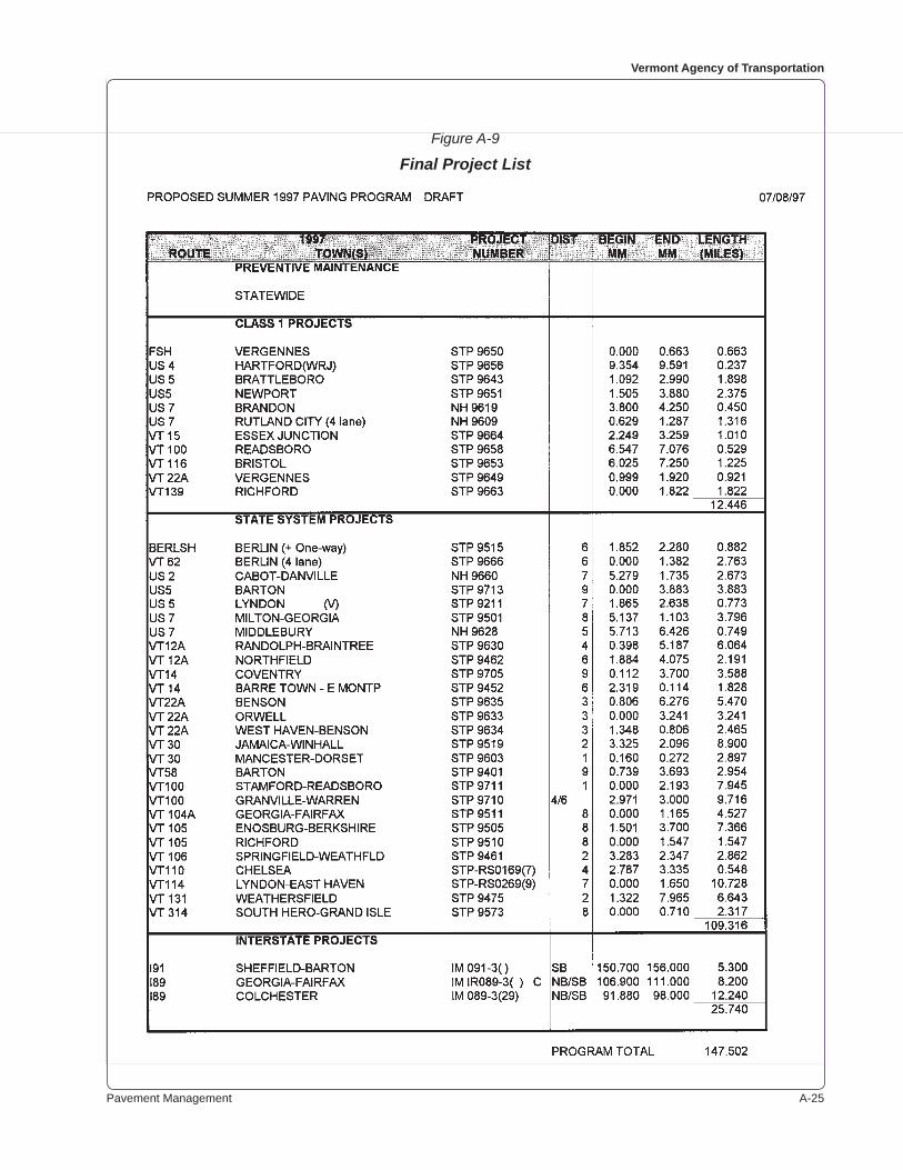
Pavement Management A-��
Vermont Agency of Transportation
Figure A-9
Final Project List
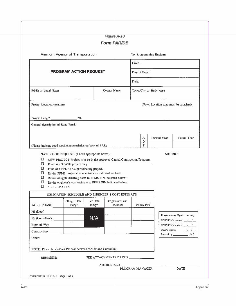
A-�� Appendix
Figure A-10
Form PAR/DB
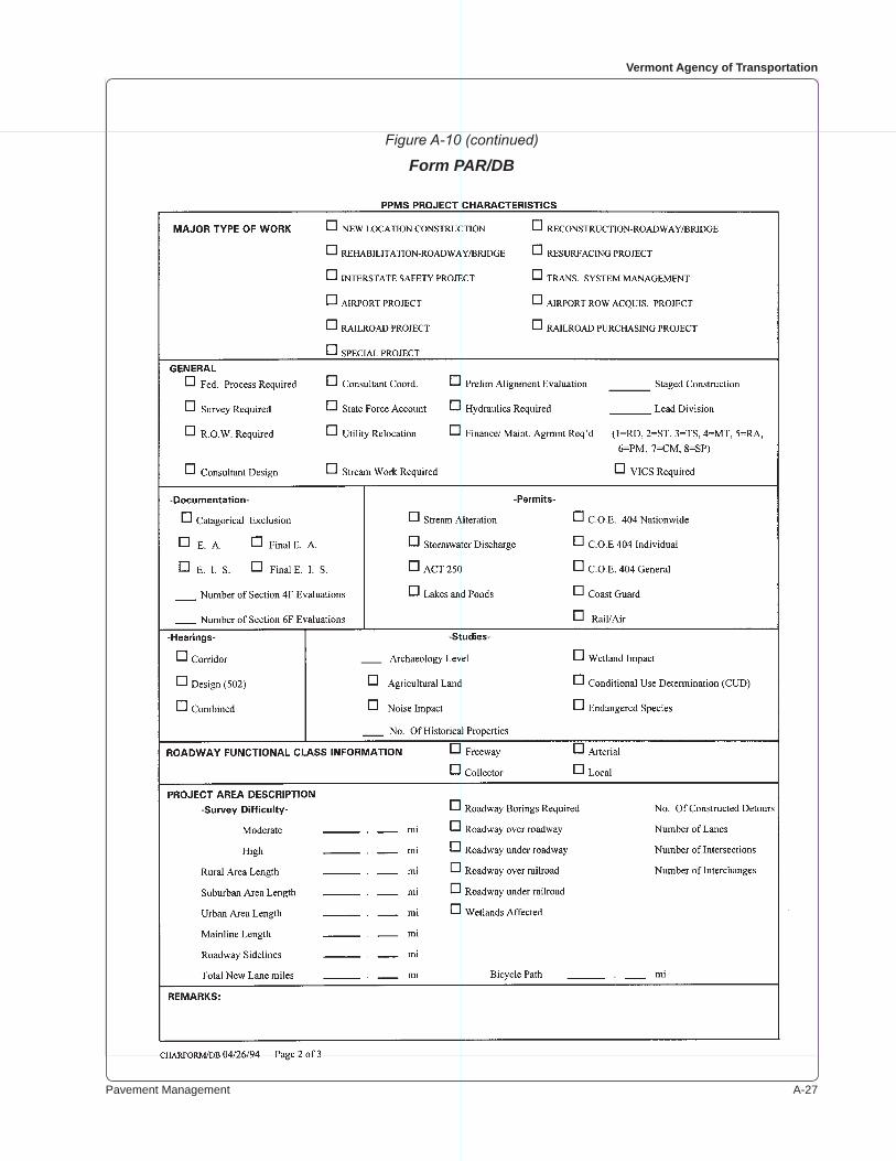
Pavement Management A-��
Vermont Agency of Transportation
Figure A-10 (continued)
Form PAR/DB
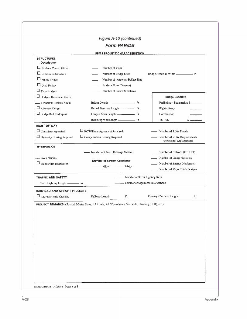
A-�� Appendix
Figure A-10 (continued)
Form PAR/DB
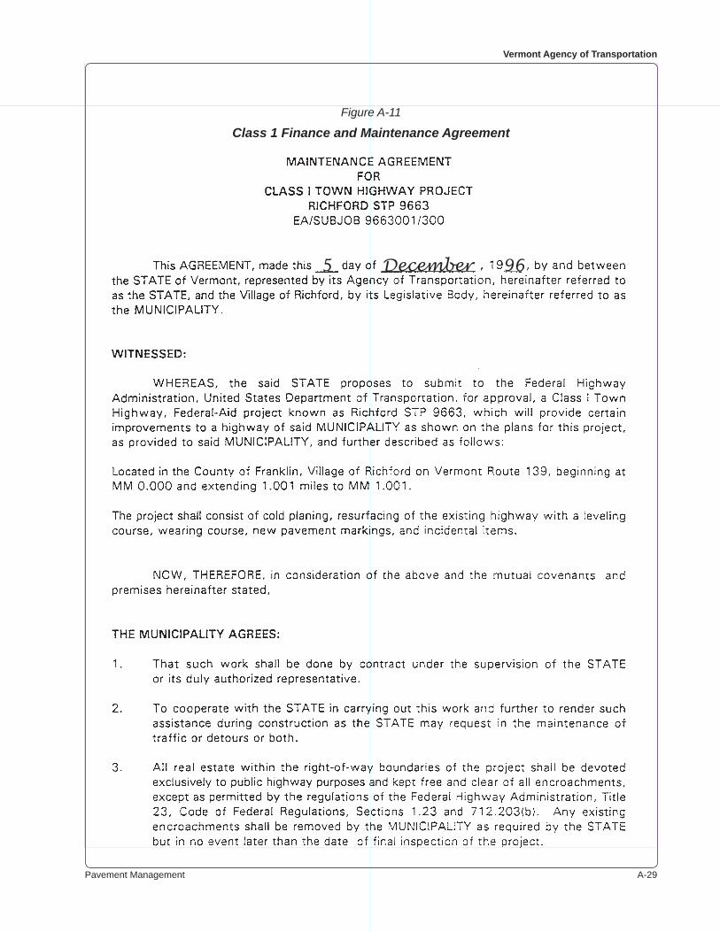
Pavement Management A-��
Vermont Agency of Transportation
Figure A-11
Class 1 Finance and Maintenance Agreement
5 December 96

A-�0 Appendix
Figure A-11 (continued)
Class 1 Finance and Maintenance Agreement
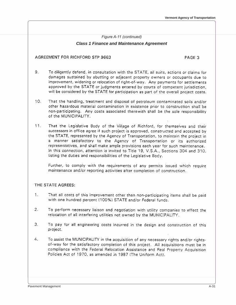
Pavement Management A-��
Vermont Agency of Transportation
Figure A-11 (continued)
Class 1 Finance and Maintenance Agreement
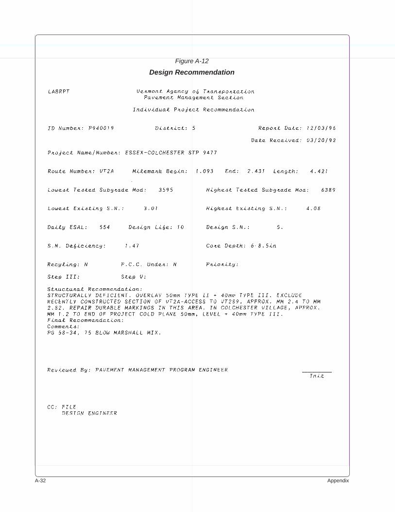
A-�� Appendix
Figure A-12
Design Recommendation
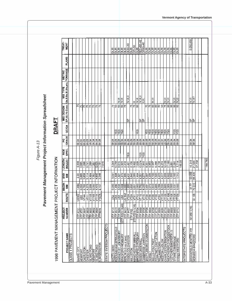
Pavement Management A-��
Vermont Agency of Transportation
Figu
re A
-13
Pave
men
t Man
agem
ent P
roje
ct In
form
atio
n Sp
read
shee
t
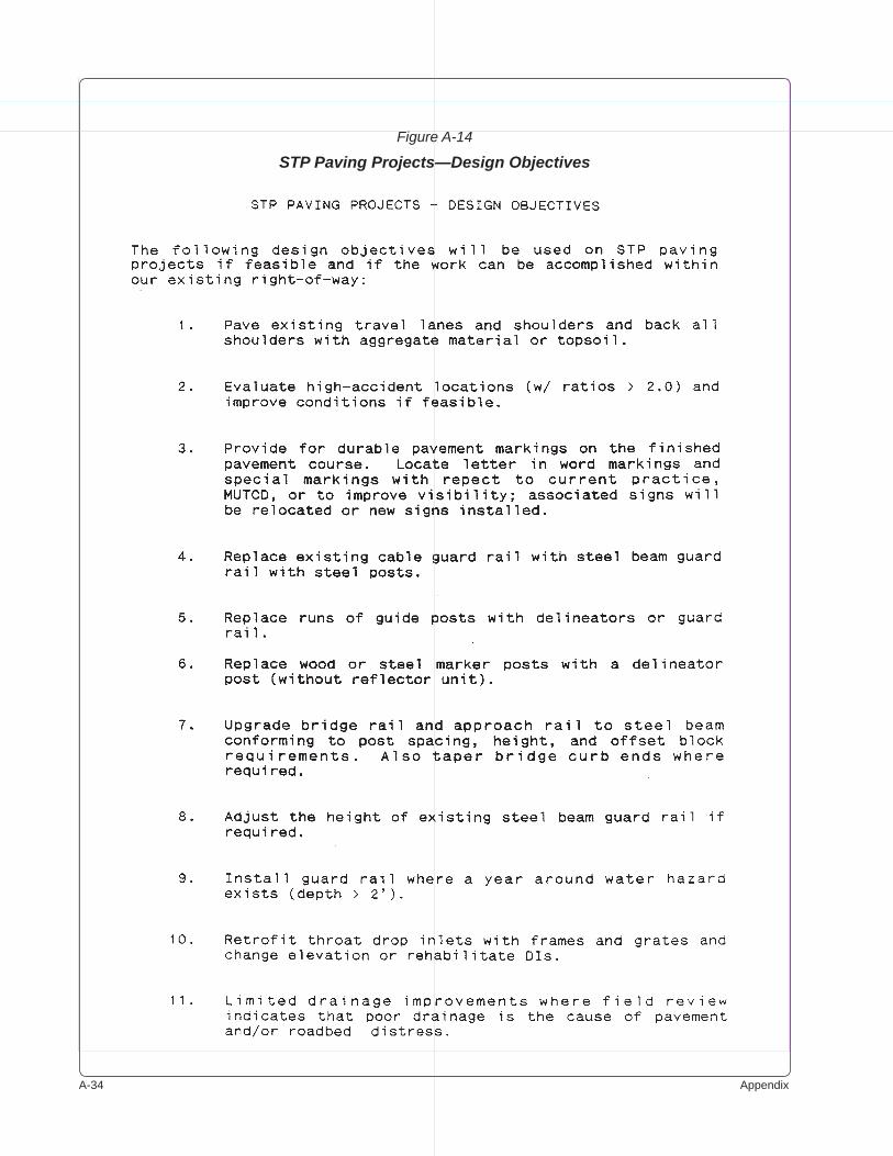
A-�� Appendix
Figure A-14
STP Paving Projects—Design Objectives
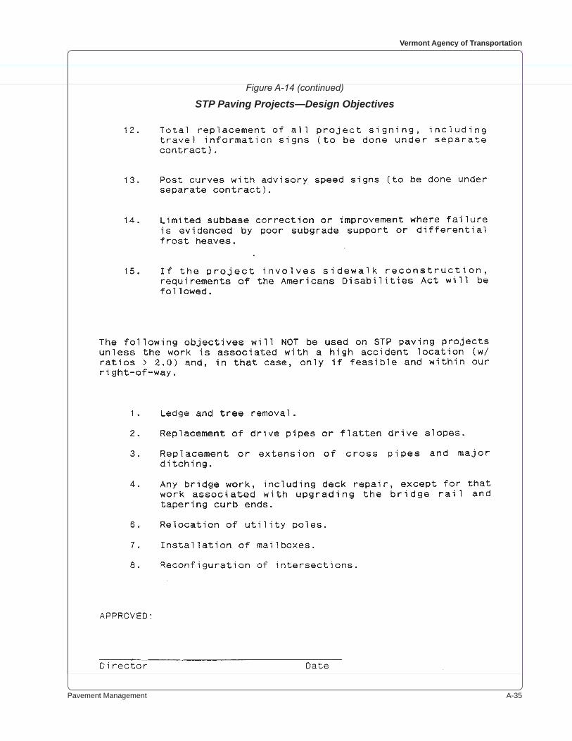
Pavement Management A-��
Vermont Agency of Transportation
Figure A-14 (continued)
STP Paving Projects—Design Objectives
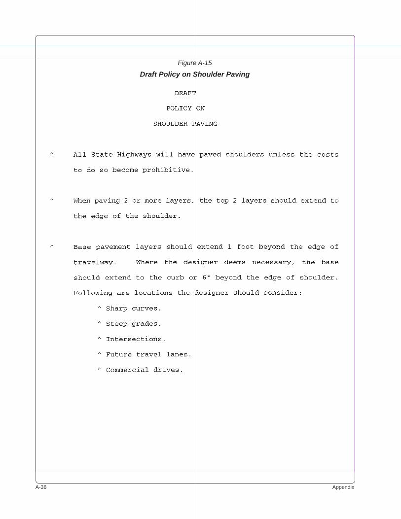
A-�� Appendix
Figure A-15
Draft Policy on Shoulder Paving
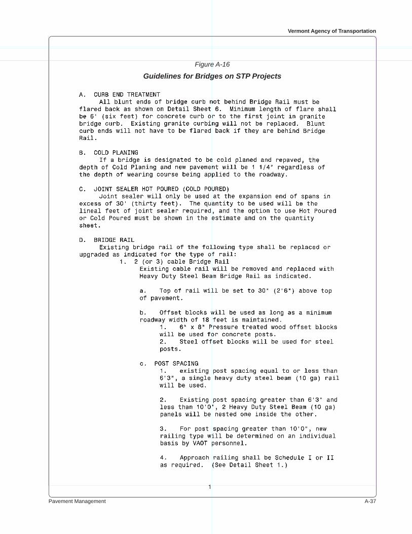
Pavement Management A-��
Vermont Agency of Transportation
Figure A-16
Guidelines for Bridges on STP Projects
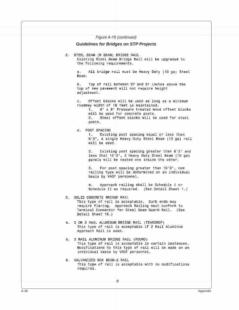
A-�� Appendix
Figure A-16 (continued)
Guidelines for Bridges on STP Projects
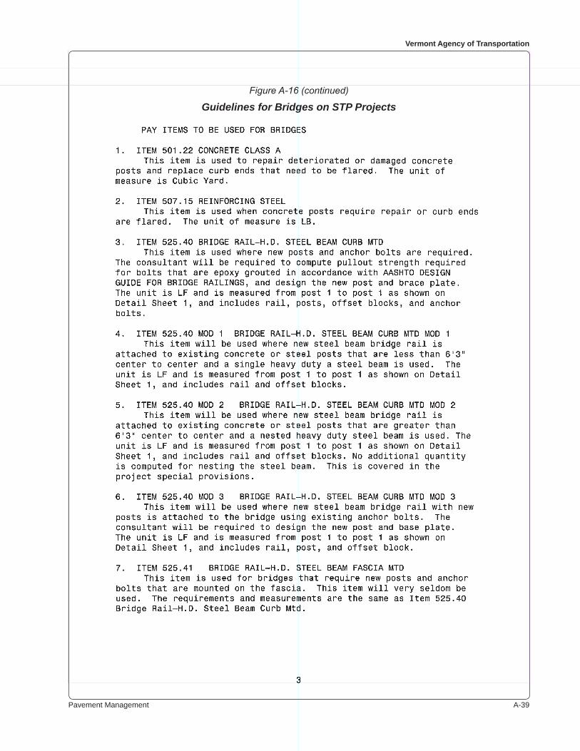
Pavement Management A-��
Vermont Agency of Transportation
Figure A-16 (continued)
Guidelines for Bridges on STP Projects
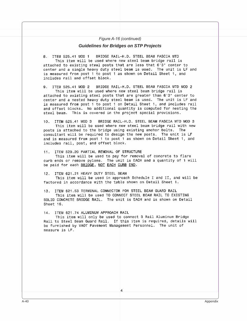
A-�0 Appendix
Figure A-16 (continued)
Guidelines for Bridges on STP Projects
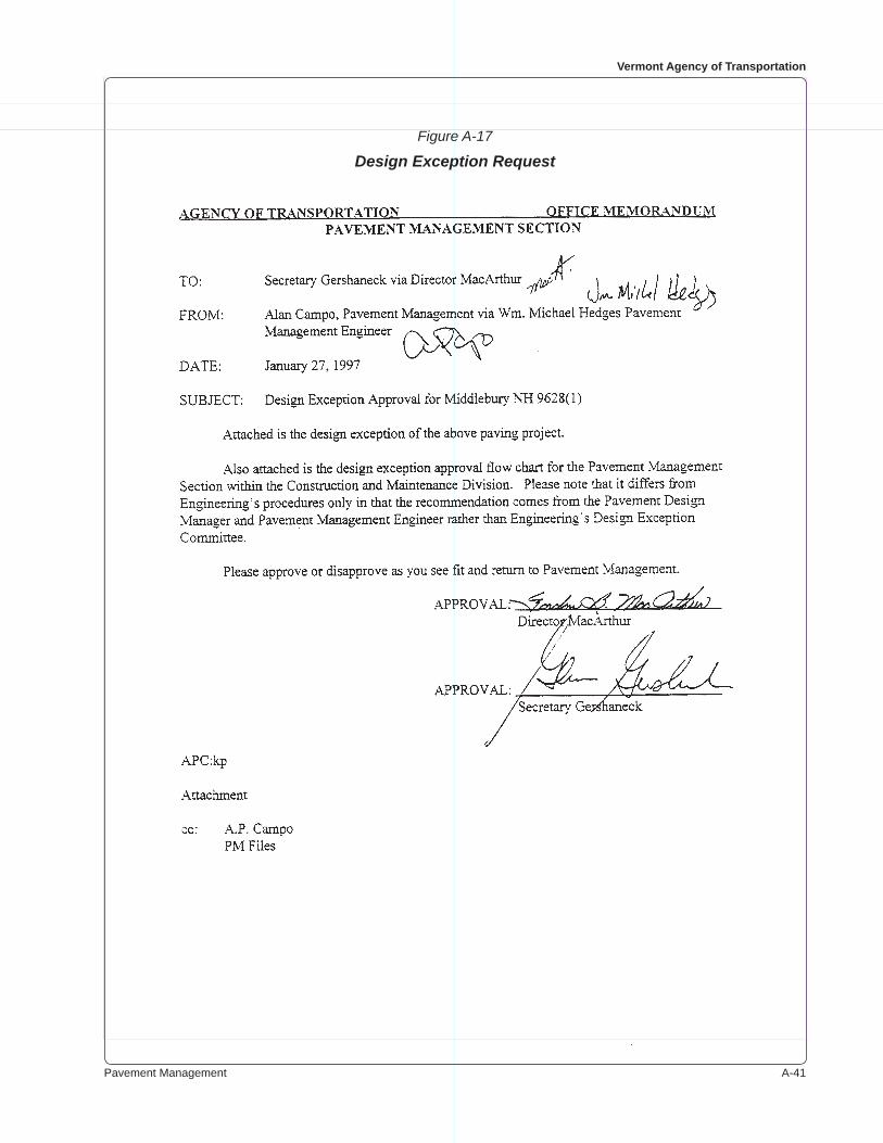
Pavement Management A-��
Vermont Agency of Transportation
Figure A-17
Design Exception Request
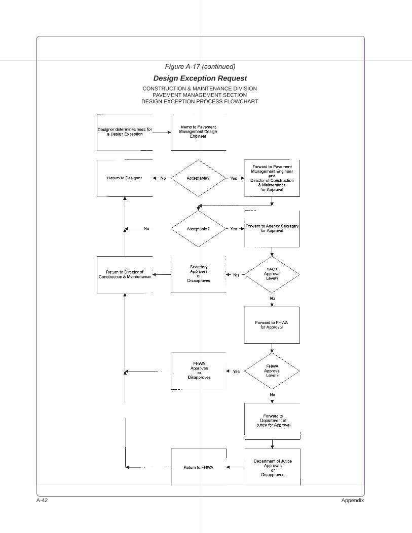
A-�� Appendix
Figure A-17 (continued)
Design Exception RequestCONSTRUCTION & MAINTENANCE DIVISION
PAVEMENT MANAGEMENT SECTIONDESIGN EXCEPTION PROCESS FLOWCHART

Pavement Management A-��
Vermont Agency of Transportation
Figure A-17 (continued)
Design Exception Request
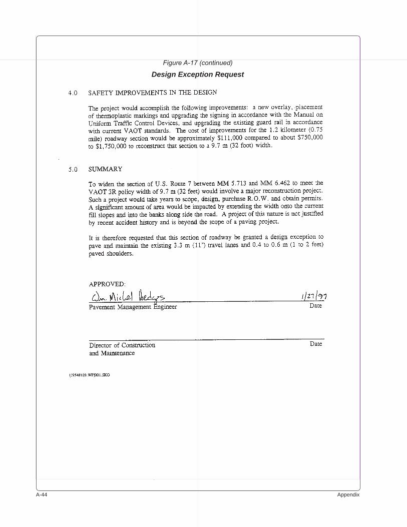
A-�� Appendix
Figure A-17 (continued)
Design Exception Request
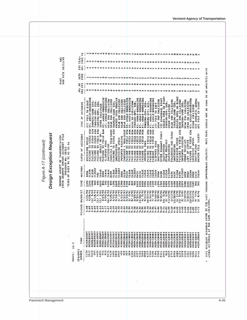
Pavement Management A-��
Vermont Agency of Transportation
Figu
re A
-17
(con
tinue
d)
Des
ign
Exce
ptio
n R
eque
st
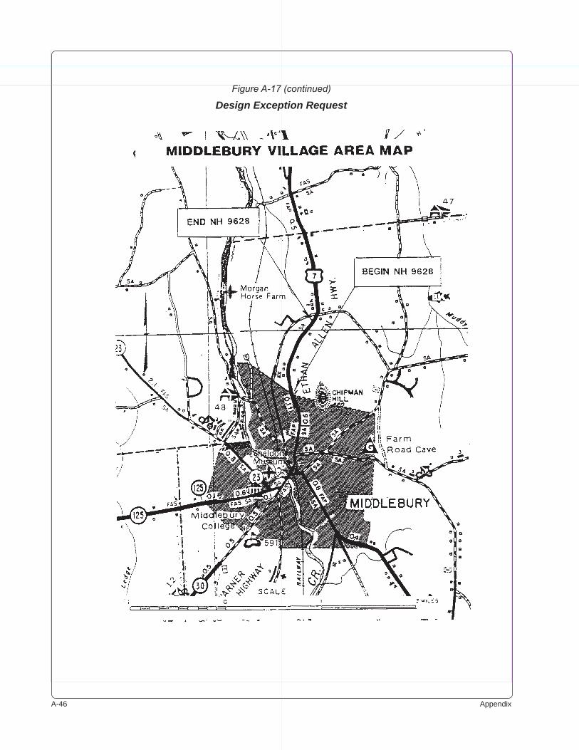
A-�� Appendix
Figure A-17 (continued)
Design Exception Request
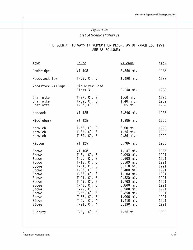
Pavement Management A-��
Vermont Agency of Transportation
Figure A-18
List of Scenic Highways
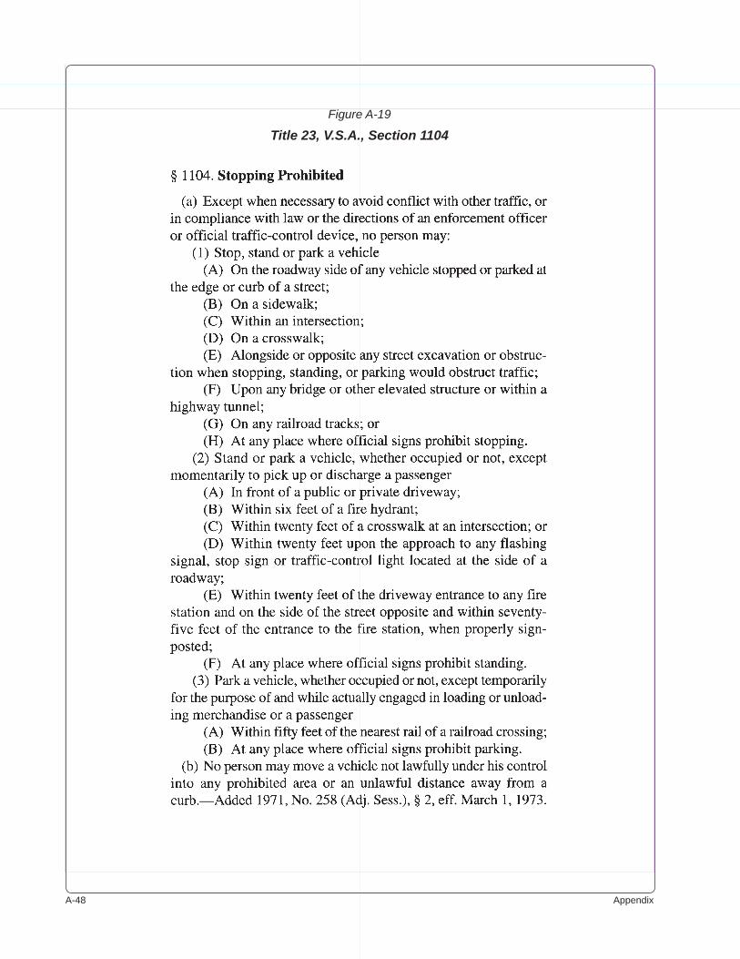
A-�� Appendix
Figure A-19
Title 23, V.S.A., Section 1104
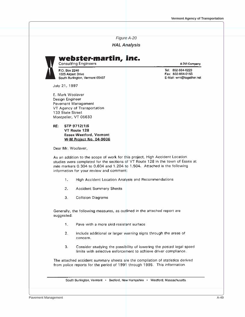
Pavement Management A-��
Vermont Agency of Transportation
Figure A-20
HAL Analysis
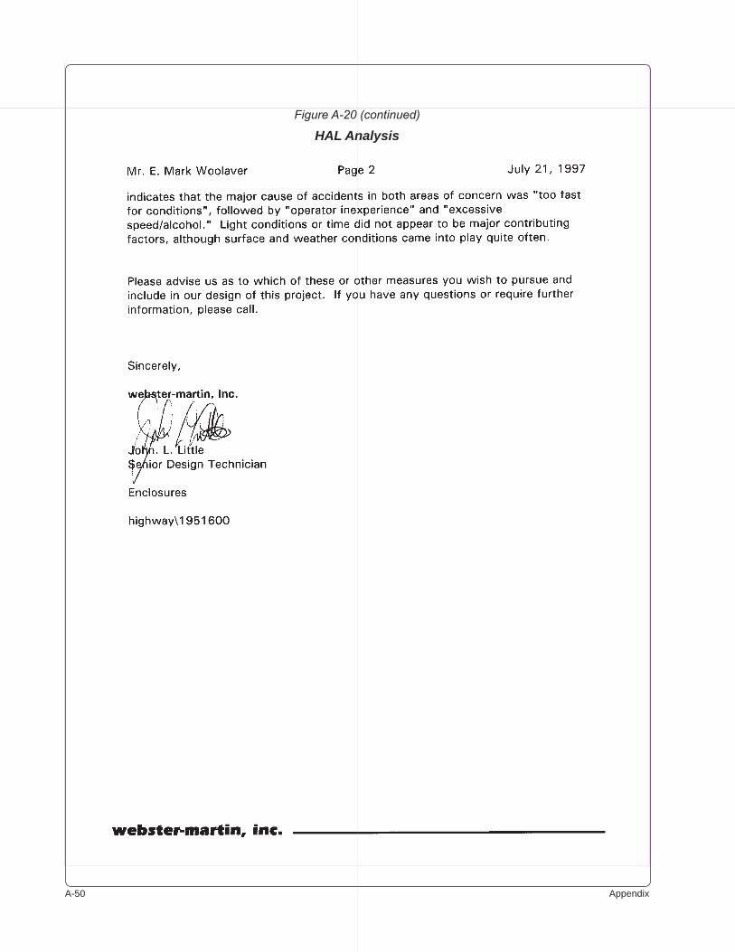
A-�0 Appendix
Figure A-20 (continued)
HAL Analysis
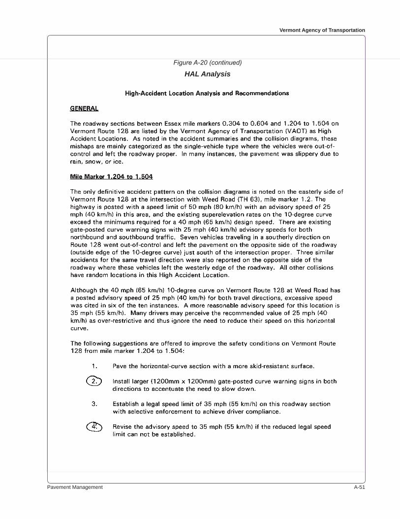
Pavement Management A-��
Vermont Agency of Transportation
Figure A-20 (continued)
HAL Analysis
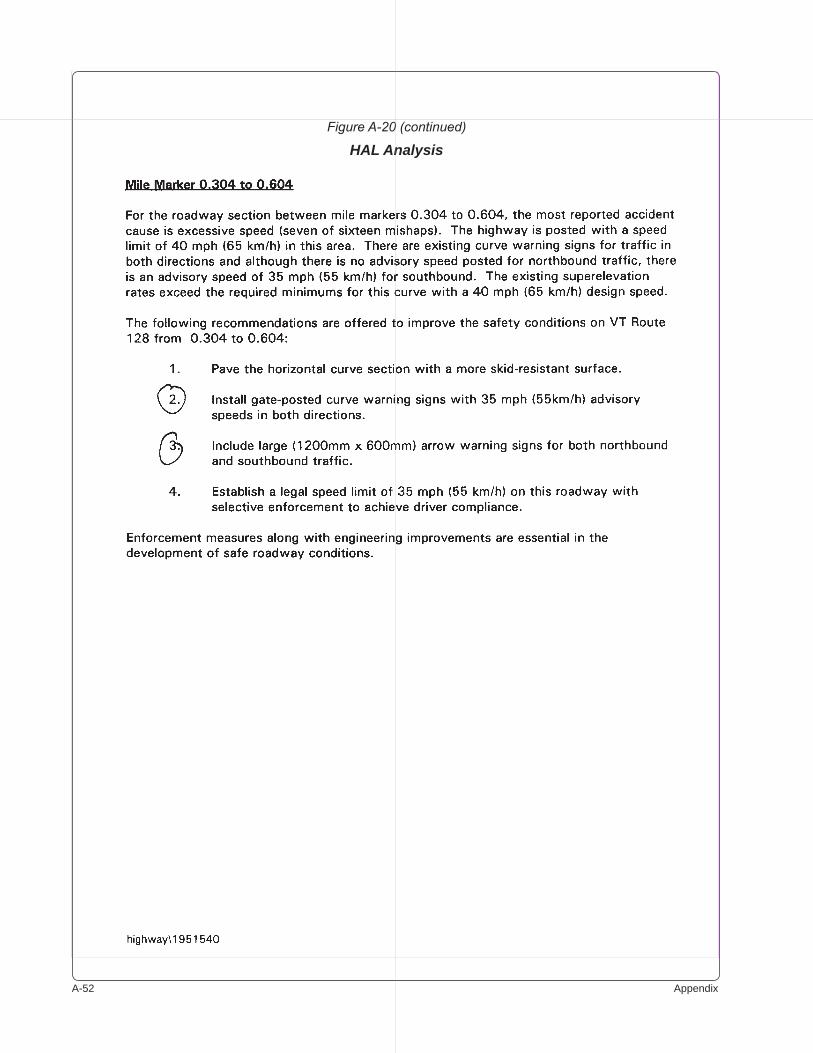
A-�� Appendix
Figure A-20 (continued)
HAL Analysis
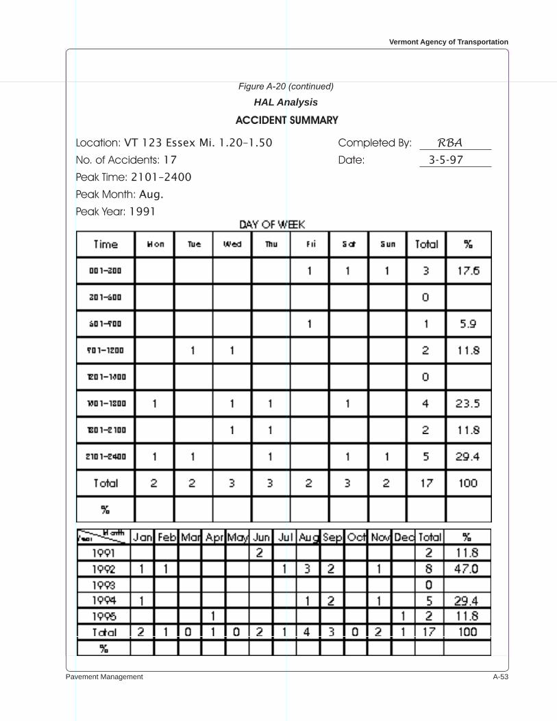
Pavement Management A-��
Vermont Agency of Transportation
Figure A-20 (continued)
HAL Analysis
Location: VT 123 Essex Mi. 1.20–1.50 Completed By: RBANo. of Accidents: 17 Date: 3-5-97
Peak Time: 2101–2400
Peak Month: Aug.
Peak Year: 1991
ACCIDENTSUMMARY
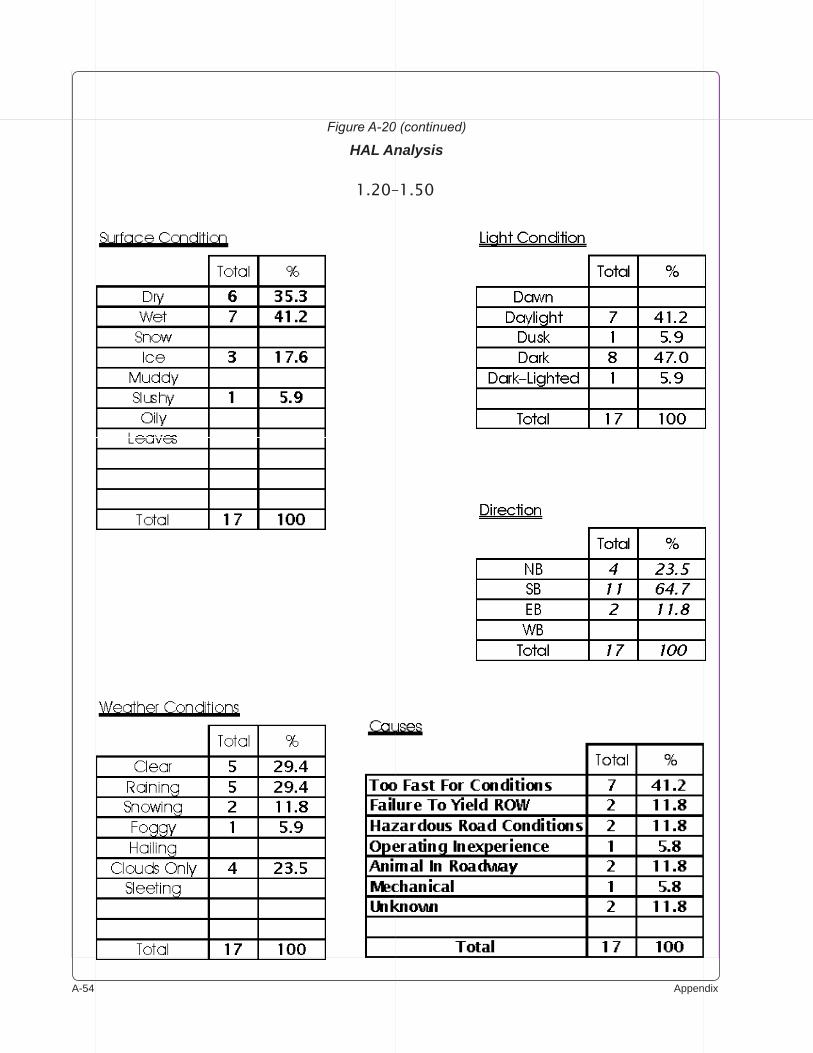
A-�� Appendix
Figure A-20 (continued)
HAL Analysis
1.20–1.50
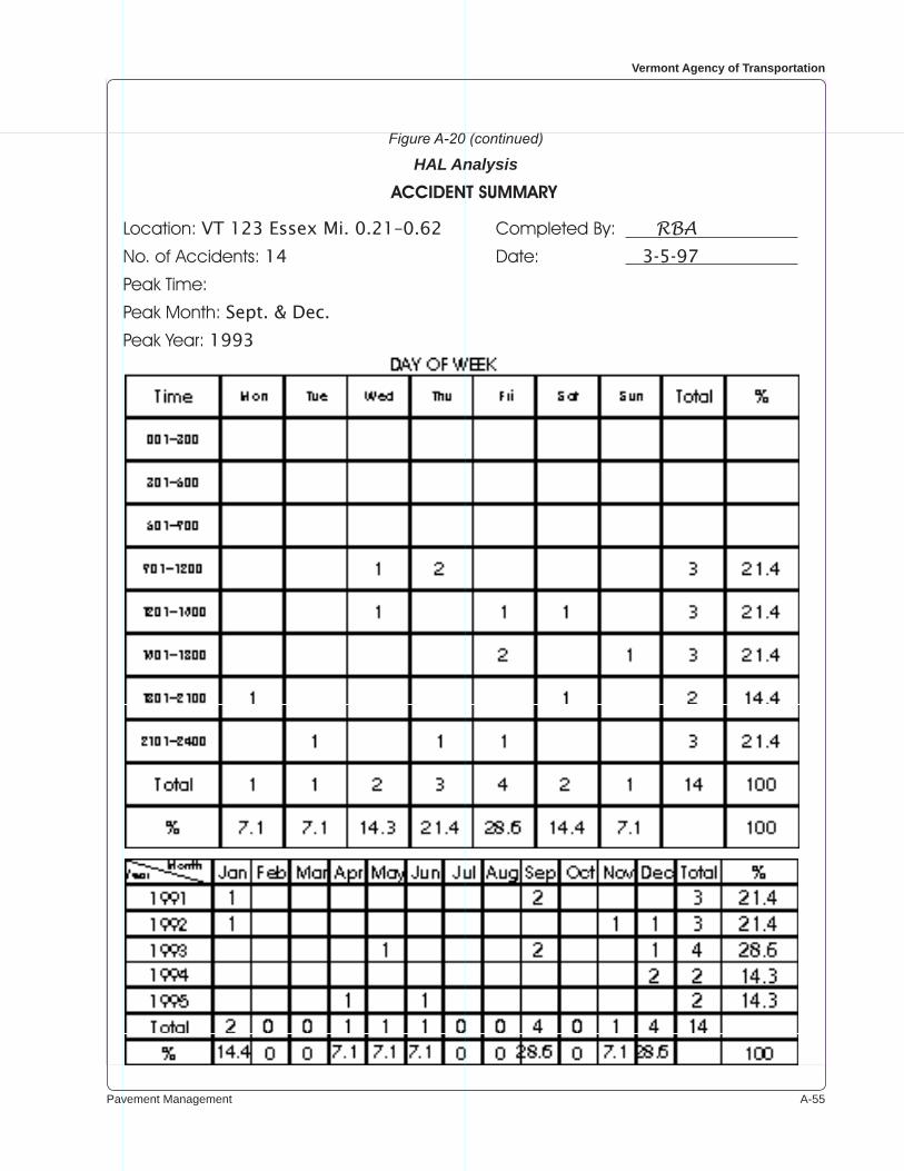
Pavement Management A-��
Vermont Agency of Transportation
Figure A-20 (continued)
HAL Analysis
ACCIDENTSUMMARY
Location: VT 123 Essex Mi. 0.21–0.62 Completed By: RBANo. of Accidents: 14 Date: 3-5-97
Peak Time:
Peak Month: Sept. & Dec.
Peak Year: 1993
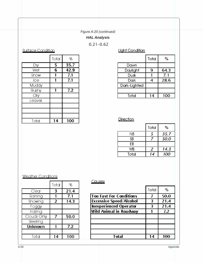
A-�� Appendix
Figure A-20 (continued)
HAL Analysis
0.21–0.62
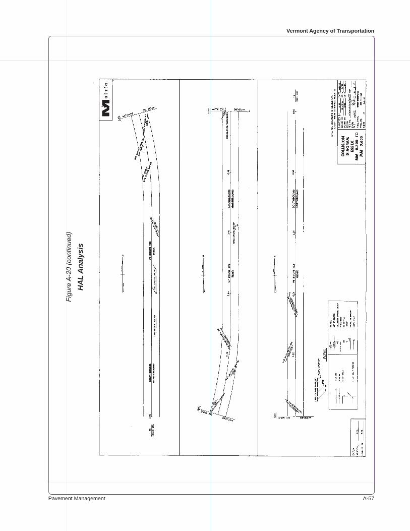
Pavement Management A-��
Vermont Agency of Transportation
Figu
re A
-20
(con
tinue
d)
HA
L A
naly
sis
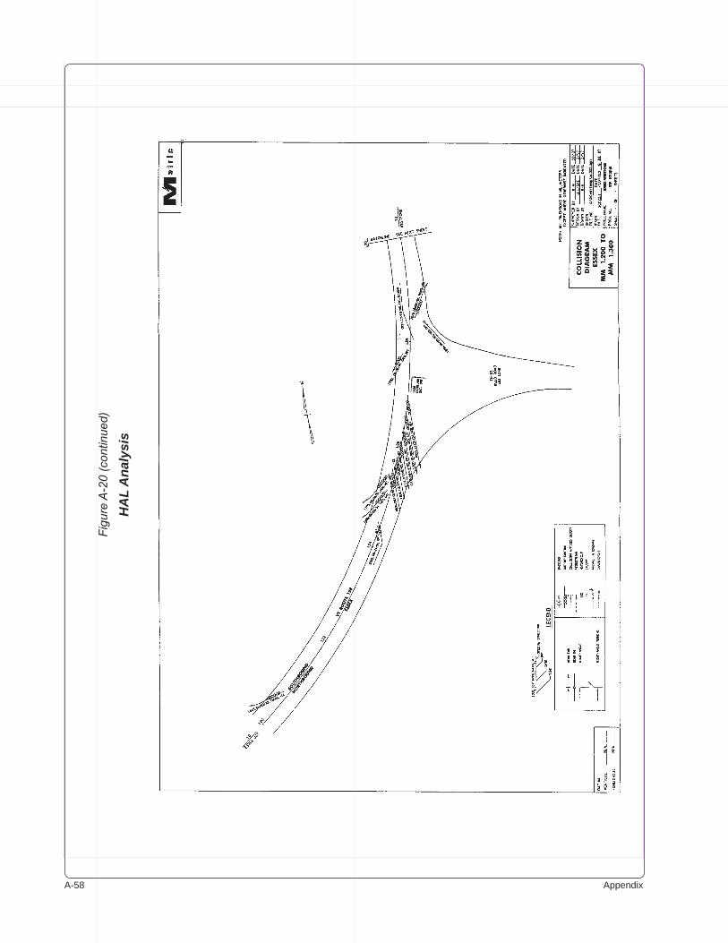
A-�� Appendix
Figu
re A
-20
(con
tinue
d)
HA
L A
naly
sis
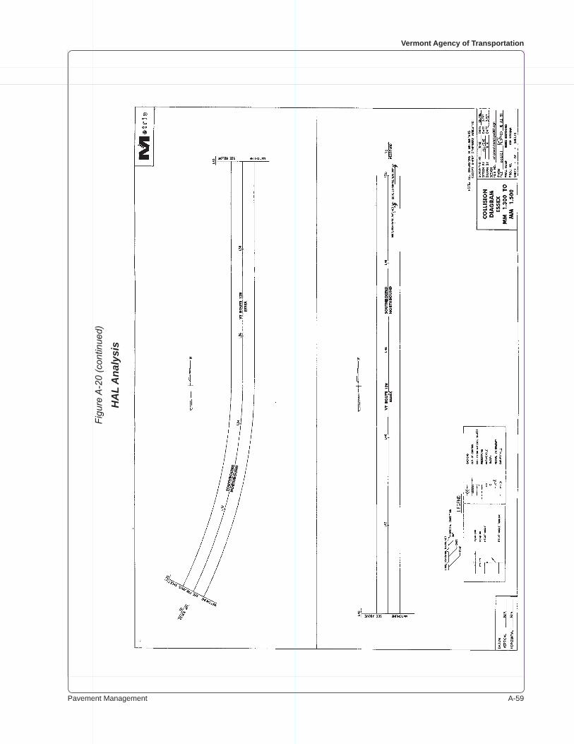
Pavement Management A-��
Vermont Agency of Transportation
Figu
re A
-20
(con
tinue
d)
HA
L A
naly
sis
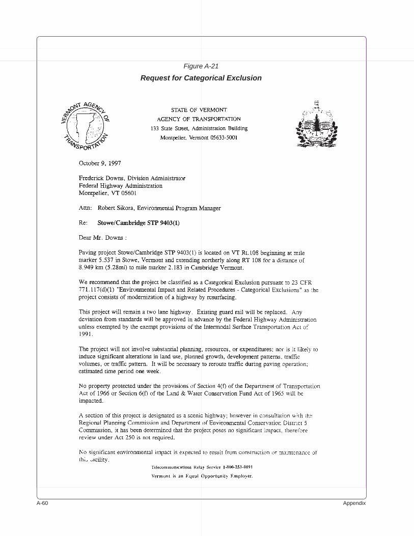
A-�0 Appendix
Figure A-21
Request for Categorical Exclusion
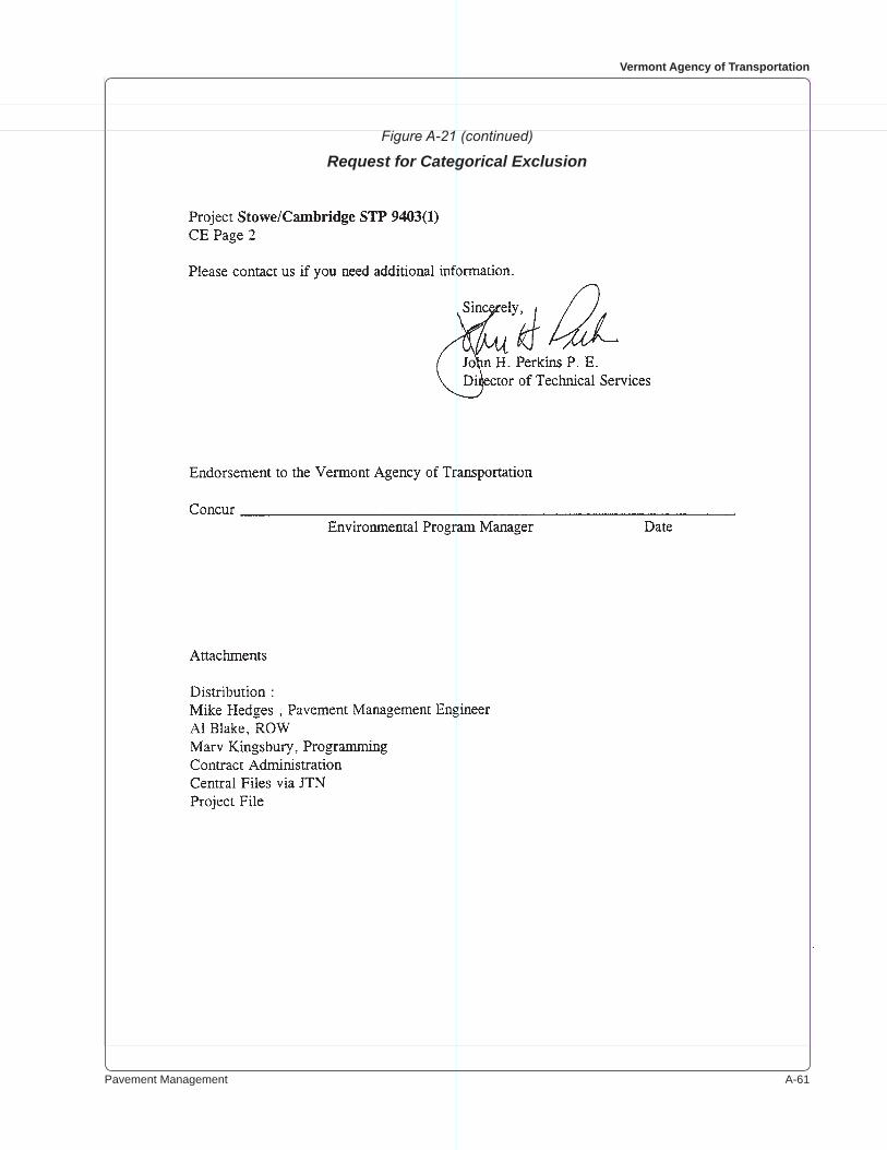
Pavement Management A-��
Vermont Agency of Transportation
Figure A-21 (continued)
Request for Categorical Exclusion
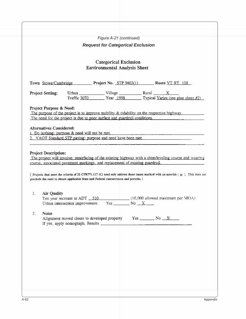
A-�� Appendix
Figure A-21 (continued)
Request for Categorical Exclusion
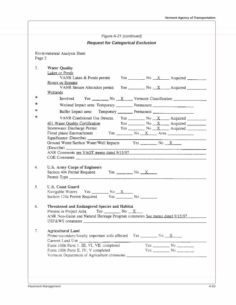
Pavement Management A-��
Vermont Agency of Transportation
Figure A-21 (continued)
Request for Categorical Exclusion
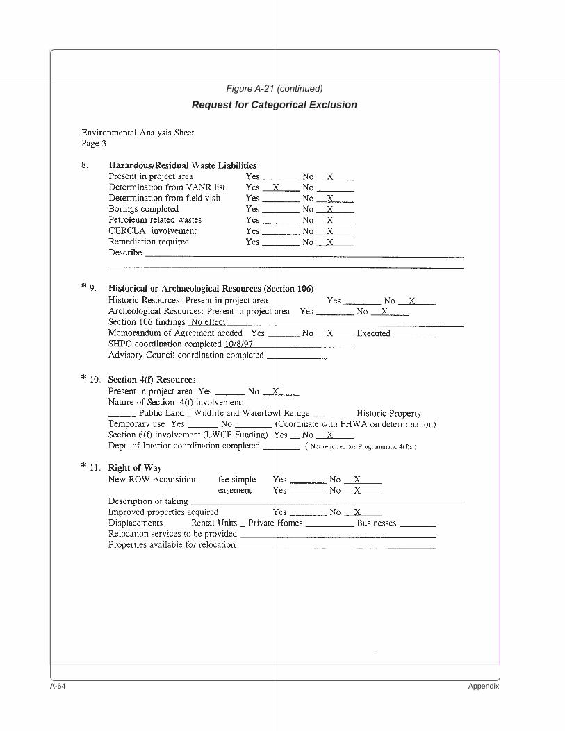
A-�� Appendix
Figure A-21 (continued)
Request for Categorical Exclusion

Pavement Management A-��
Vermont Agency of Transportation
Figure A-21 (continued)
Request for Categorical Exclusion

A-�� Appendix
Figure A-21 (continued)
Request for Categorical Exclusion
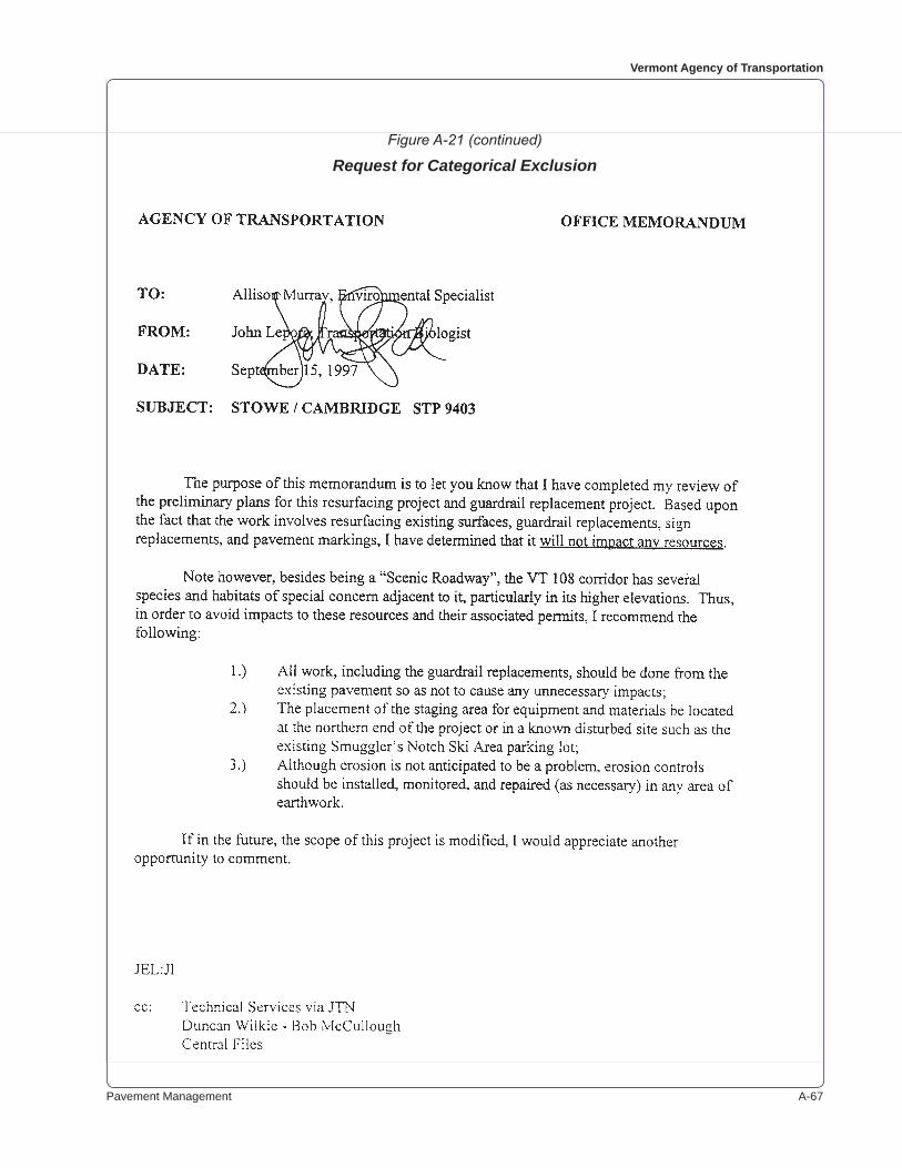
Pavement Management A-��
Vermont Agency of Transportation
Figure A-21 (continued)
Request for Categorical Exclusion
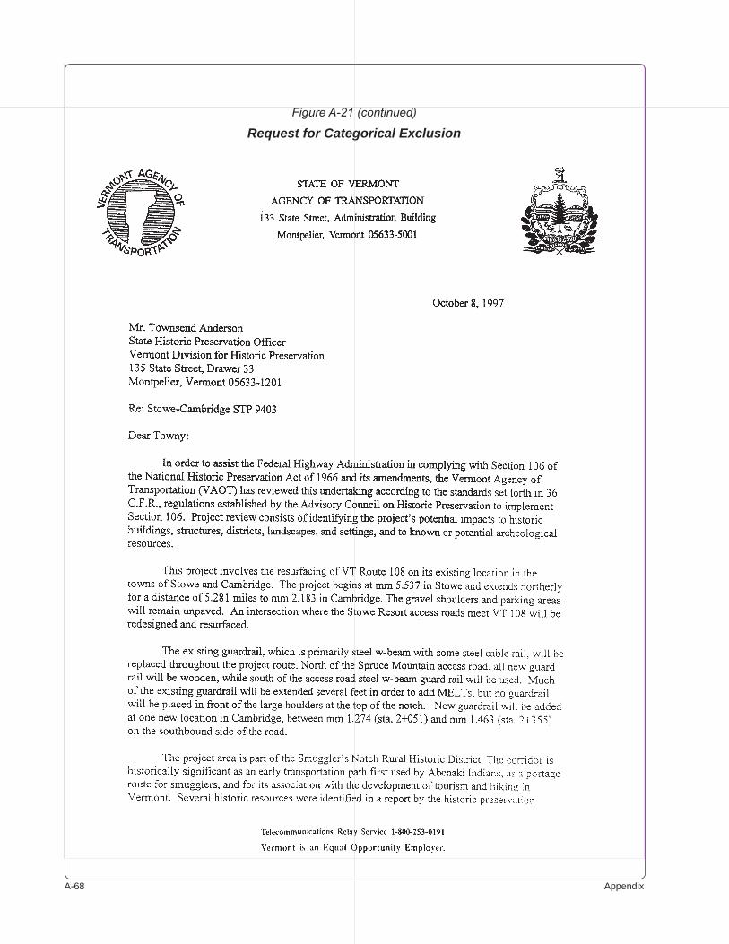
A-�� Appendix
Figure A-21 (continued)
Request for Categorical Exclusion
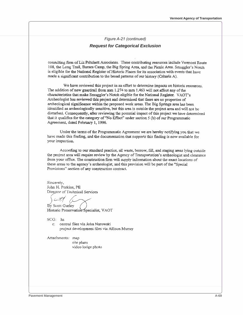
Pavement Management A-��
Vermont Agency of Transportation
Figure A-21 (continued)
Request for Categorical Exclusion

A-�0 Appendix
Figure A-22
Title 19, V.S.A., Section 306a
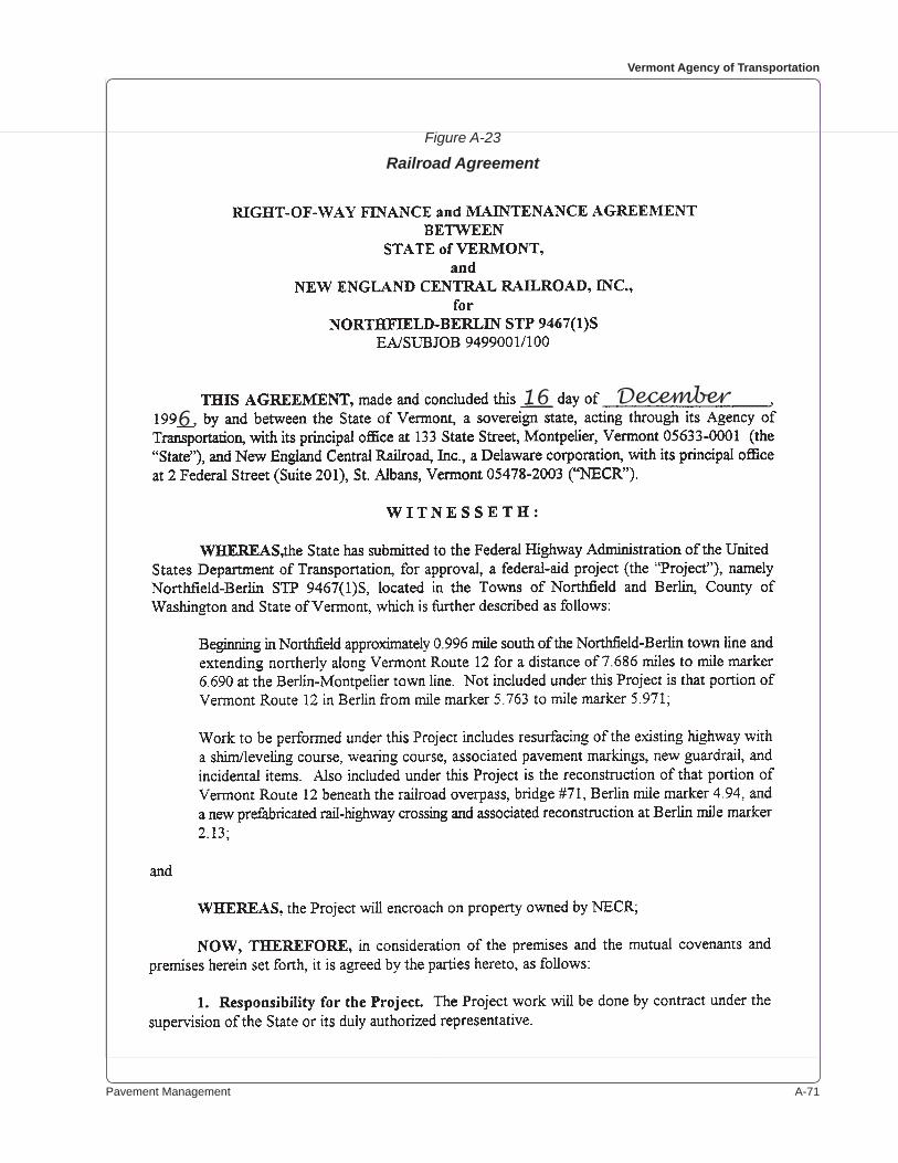
Pavement Management A-��
Vermont Agency of Transportation
Figure A-23
Railroad Agreement
16 December6
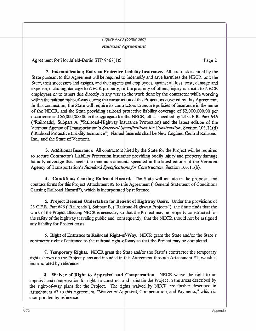
A-�� Appendix
Figure A-23 (continued)
Railroad Agreement
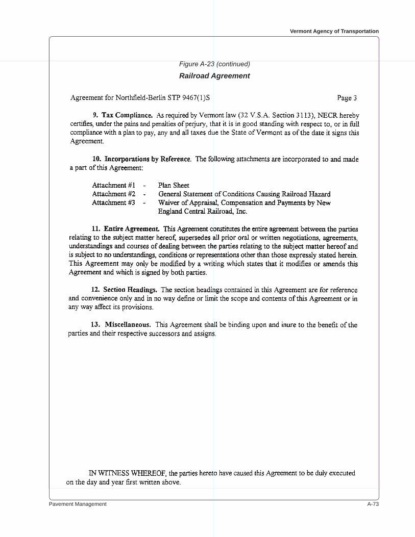
Pavement Management A-��
Vermont Agency of Transportation
Figure A-23 (continued)
Railroad Agreement
A-�� Appendix
Figure A-23 (continued)
Railroad Agreement
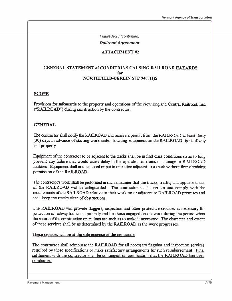
Pavement Management A-��
Vermont Agency of Transportation
Figure A-23 (continued)
Railroad Agreement
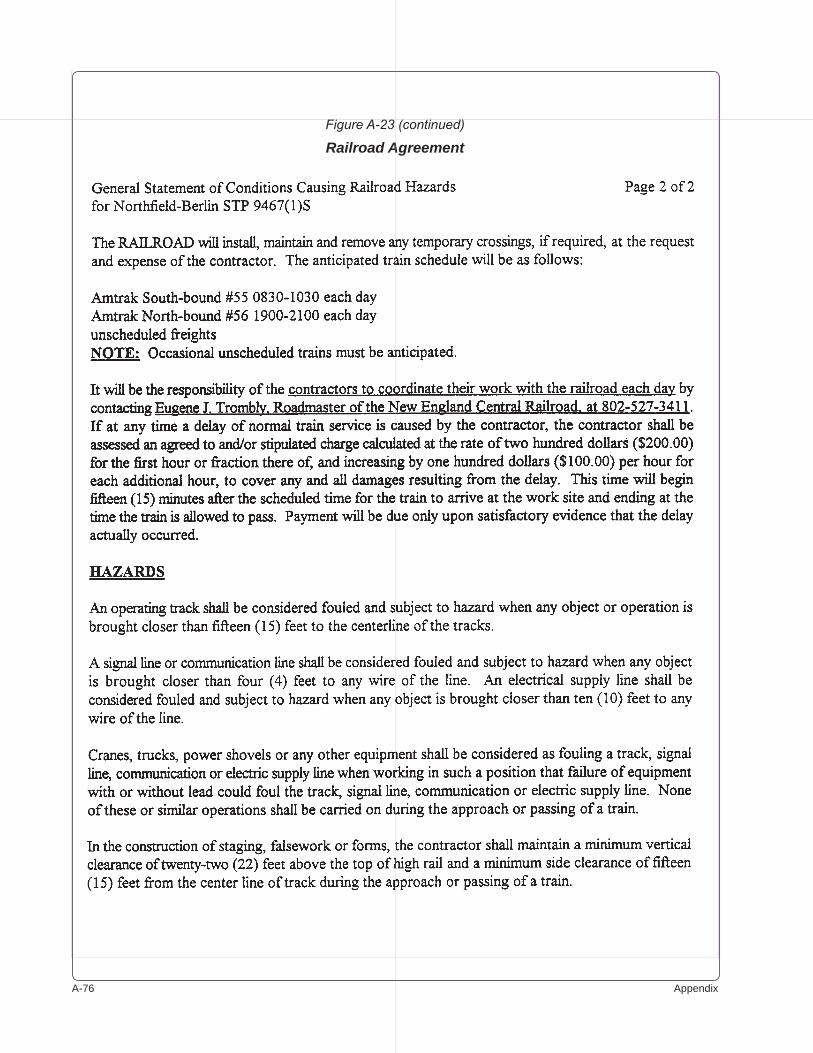
A-�� Appendix
Figure A-23 (continued)
Railroad Agreement
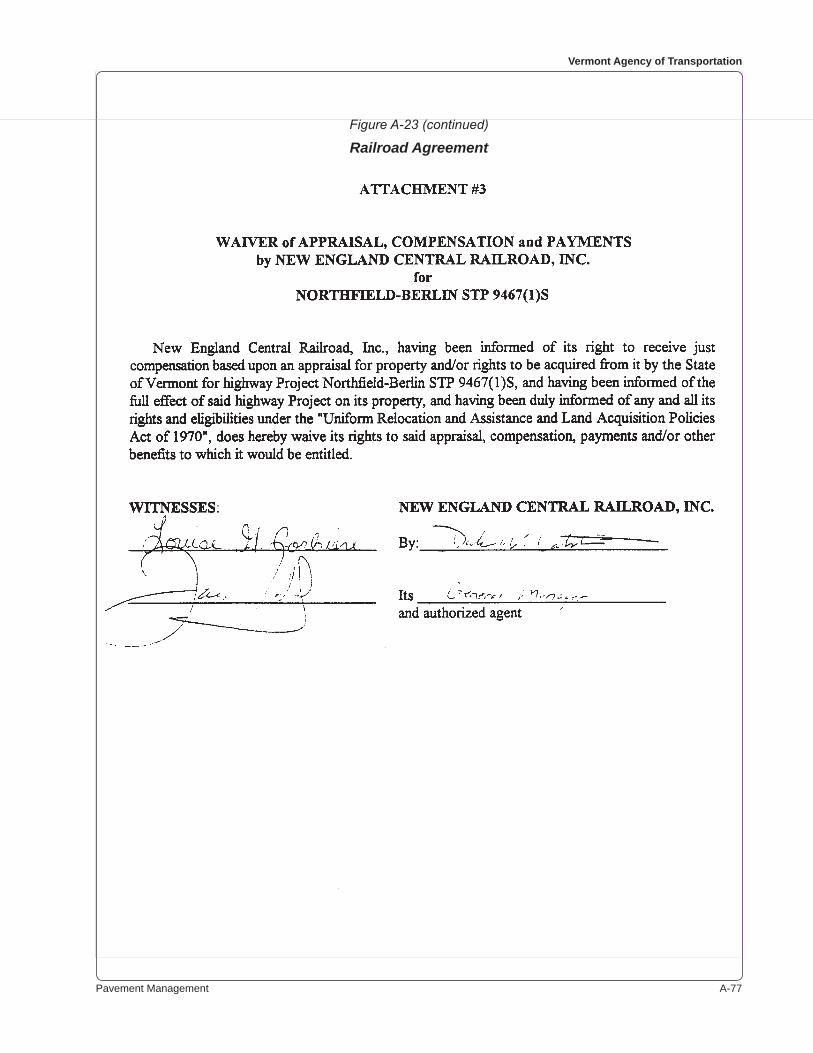
Pavement Management A-��
Vermont Agency of Transportation
Figure A-23 (continued)
Railroad Agreement
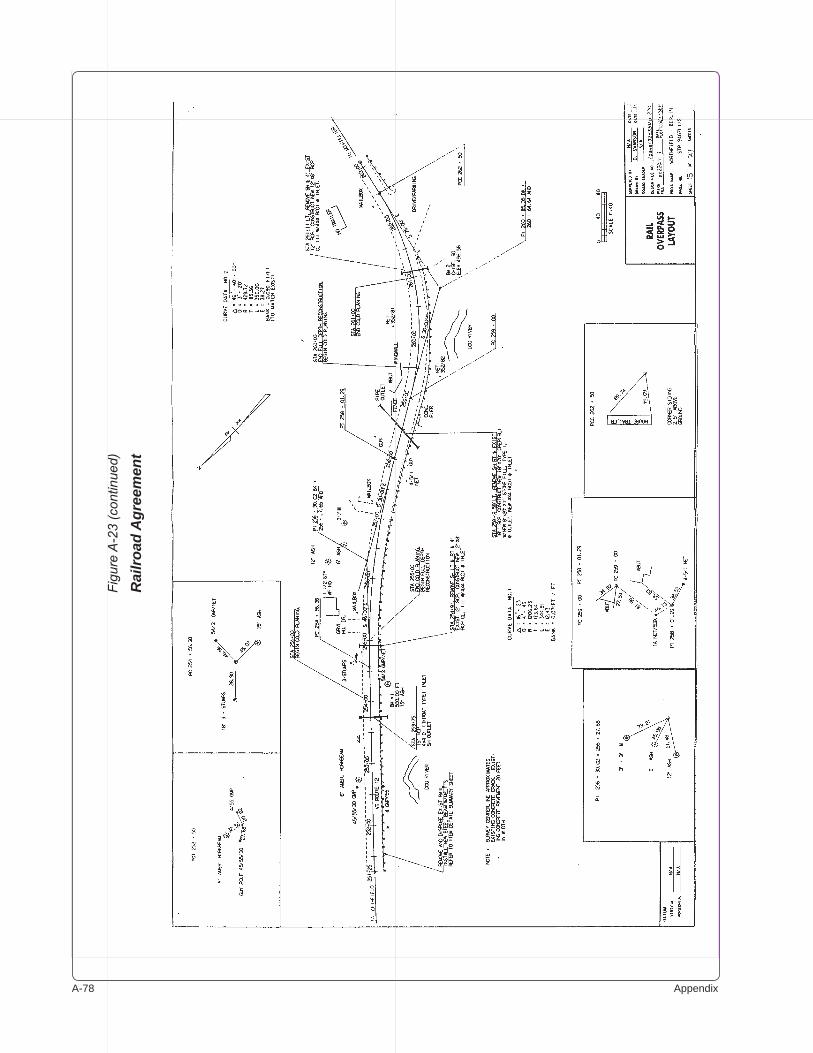
A-�� Appendix
Figu
re A
-23
(con
tinue
d)
Rai
lroad
Agr
eem
ent
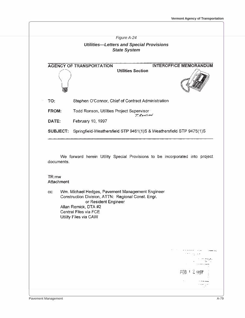
Pavement Management A-��
Vermont Agency of Transportation
Figure A-24
Utilities—Letters and Special ProvisionsState System

A-�0 Appendix
Figure A-24 (continued)
Utilities—Letters and Special ProvisionsState System
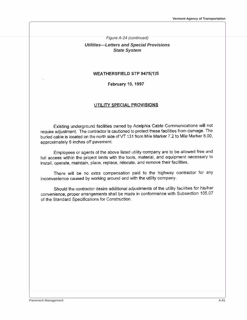
Pavement Management A-��
Vermont Agency of Transportation
Figure A-24 (continued)
Utilities—Letters and Special ProvisionsState System
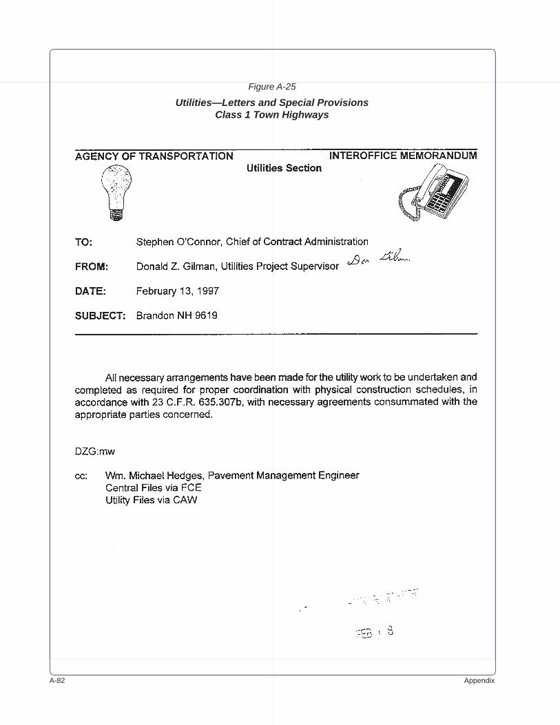
A-�� Appendix
Figure A-25
Utilities—Letters and Special ProvisionsClass 1 Town Highways

Pavement Management A-��
Vermont Agency of Transportation
Figure A-25 (continued)
Utilities—Letters and Special ProvisionsClass 1 Town Highways
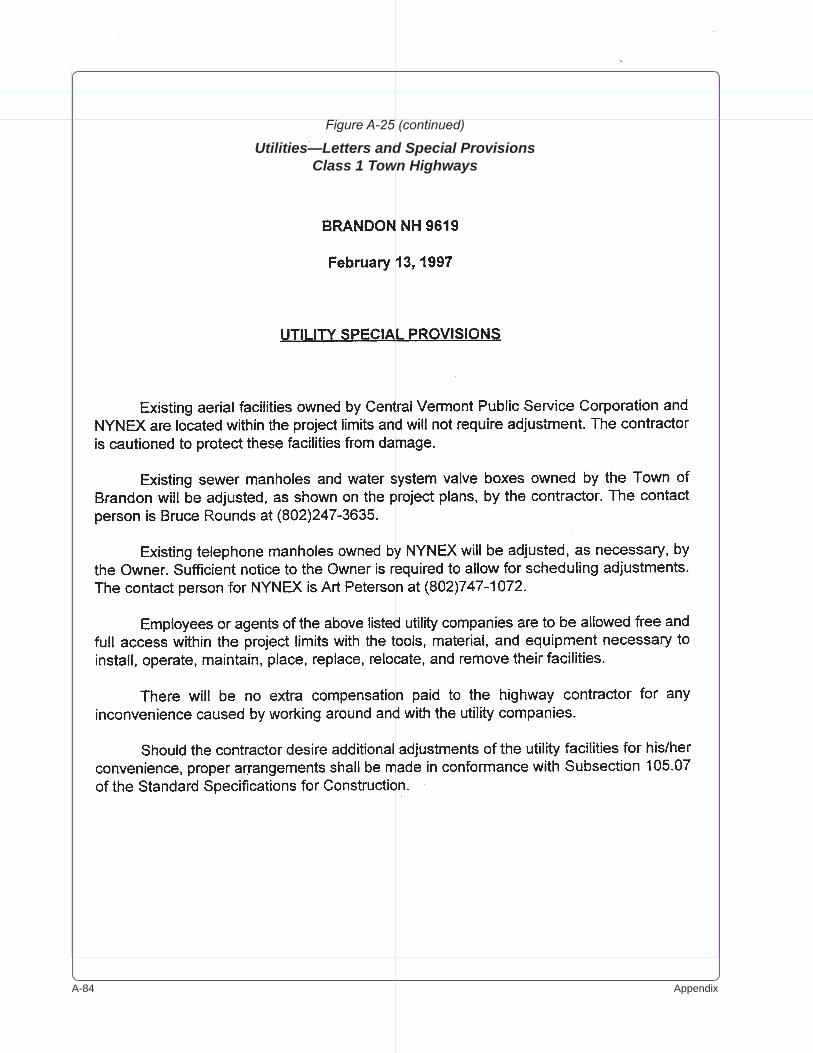
A-�� Appendix
Figure A-25 (continued)
Utilities—Letters and Special ProvisionsClass 1 Town Highways
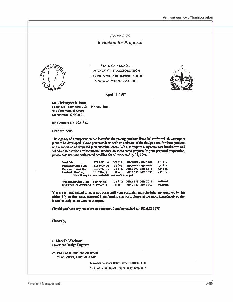
Pavement Management A-��
Vermont Agency of Transportation
Figure A-26
Invitation for Proposal
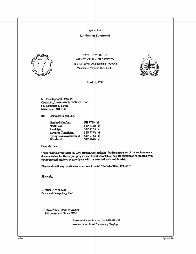
A-�� Appendix
Figure A-27
Notice to Proceed
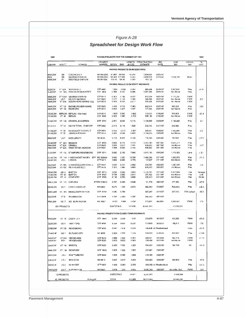
Pavement Management A-��
Vermont Agency of Transportation
Figure A-28
Spreadsheet for Design Work Flow
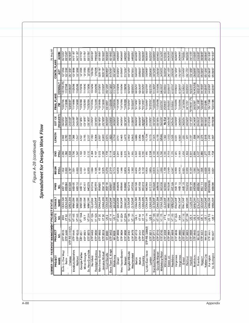
A-�� Appendix
Figu
re A
-28
(con
tinue
d)
Spre
adsh
eet f
or D
esig
n W
ork
Flow

Pavement Management A-��
Vermont Agency of Transportation
Figure A-29
Plan Sheets
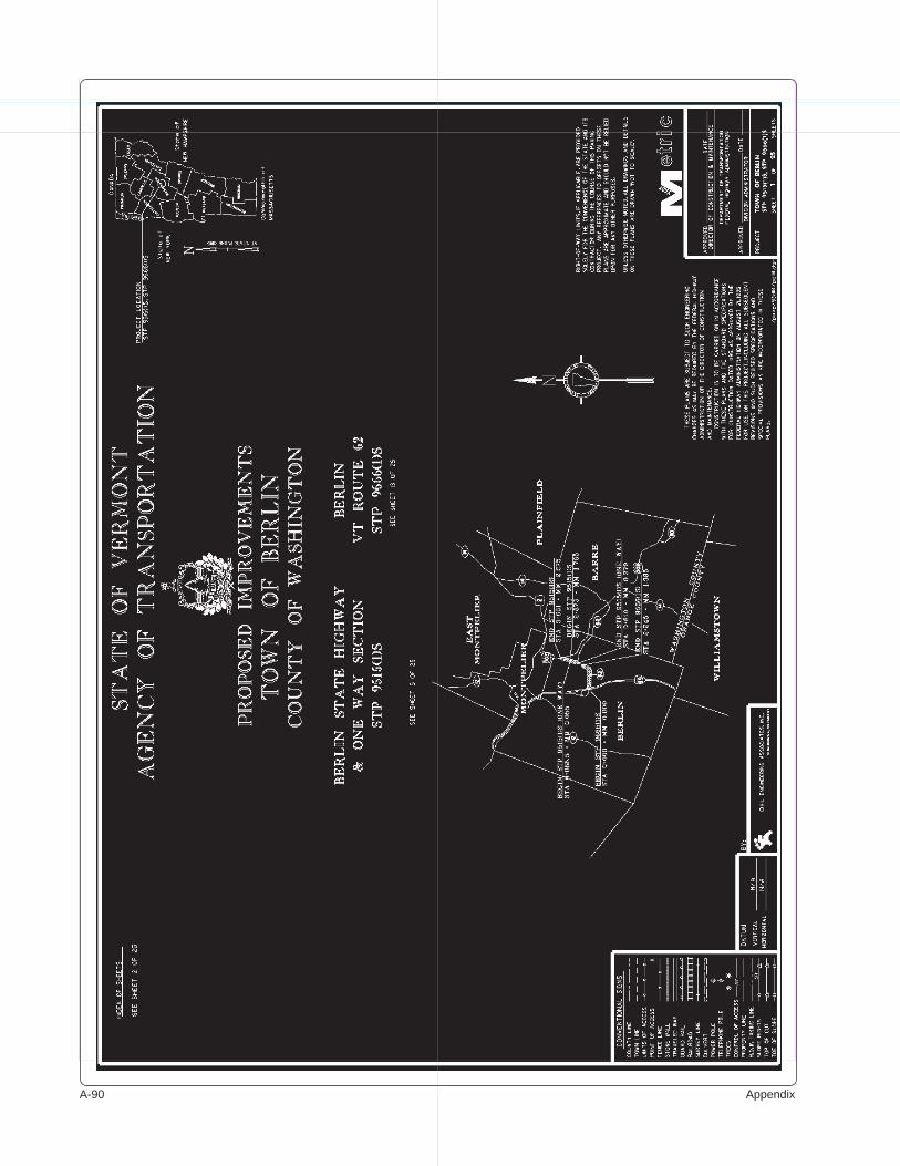
A-�0 Appendix
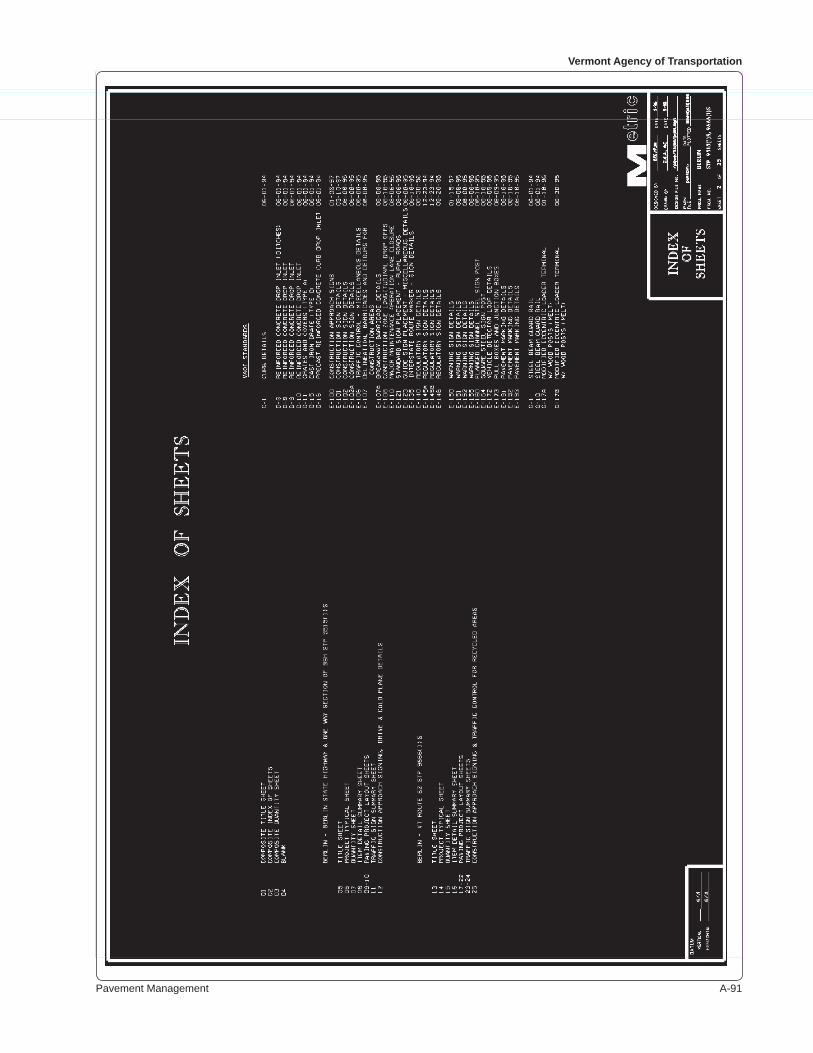
Pavement Management A-��
Vermont Agency of Transportation
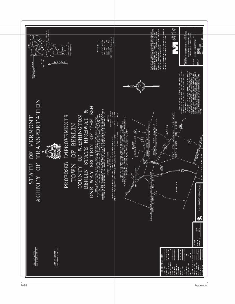
A-�� Appendix

Pavement Management A-��
Vermont Agency of Transportation
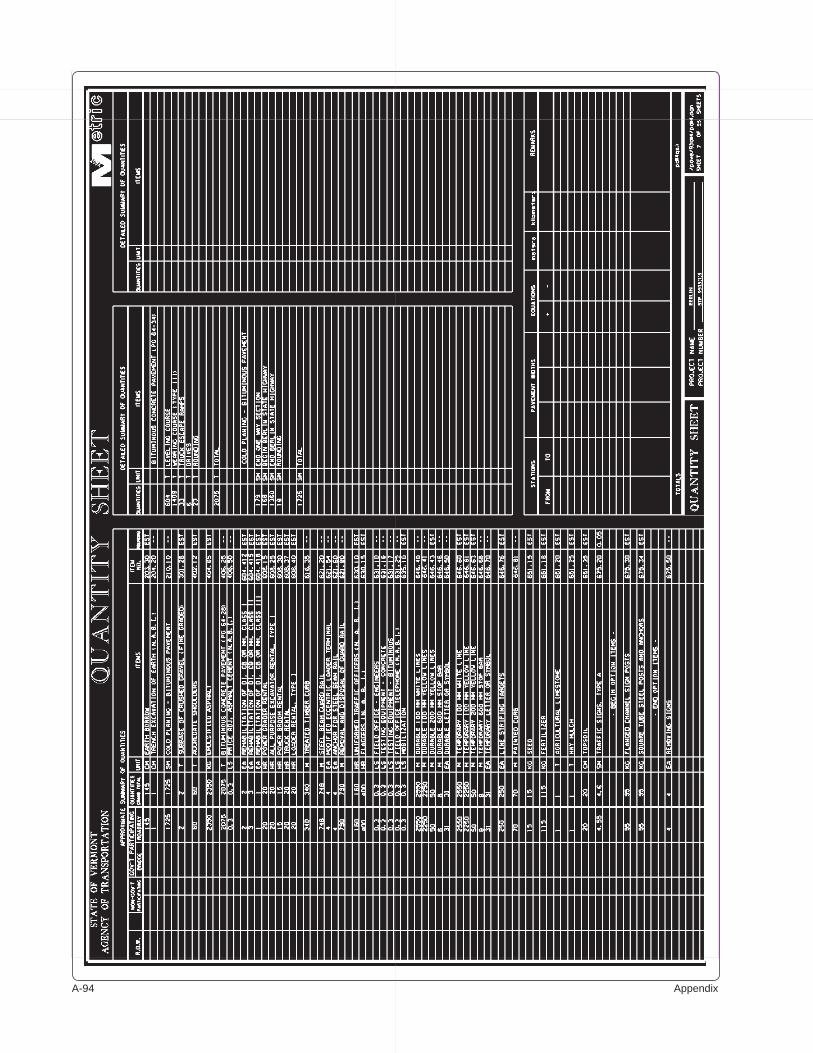
A-�� Appendix
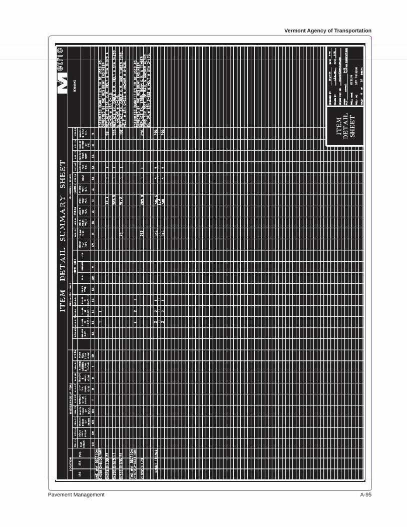
Pavement Management A-��
Vermont Agency of Transportation
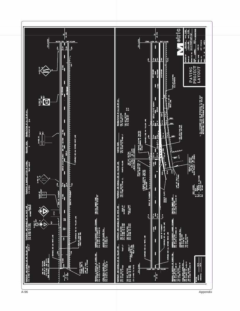
A-�� Appendix
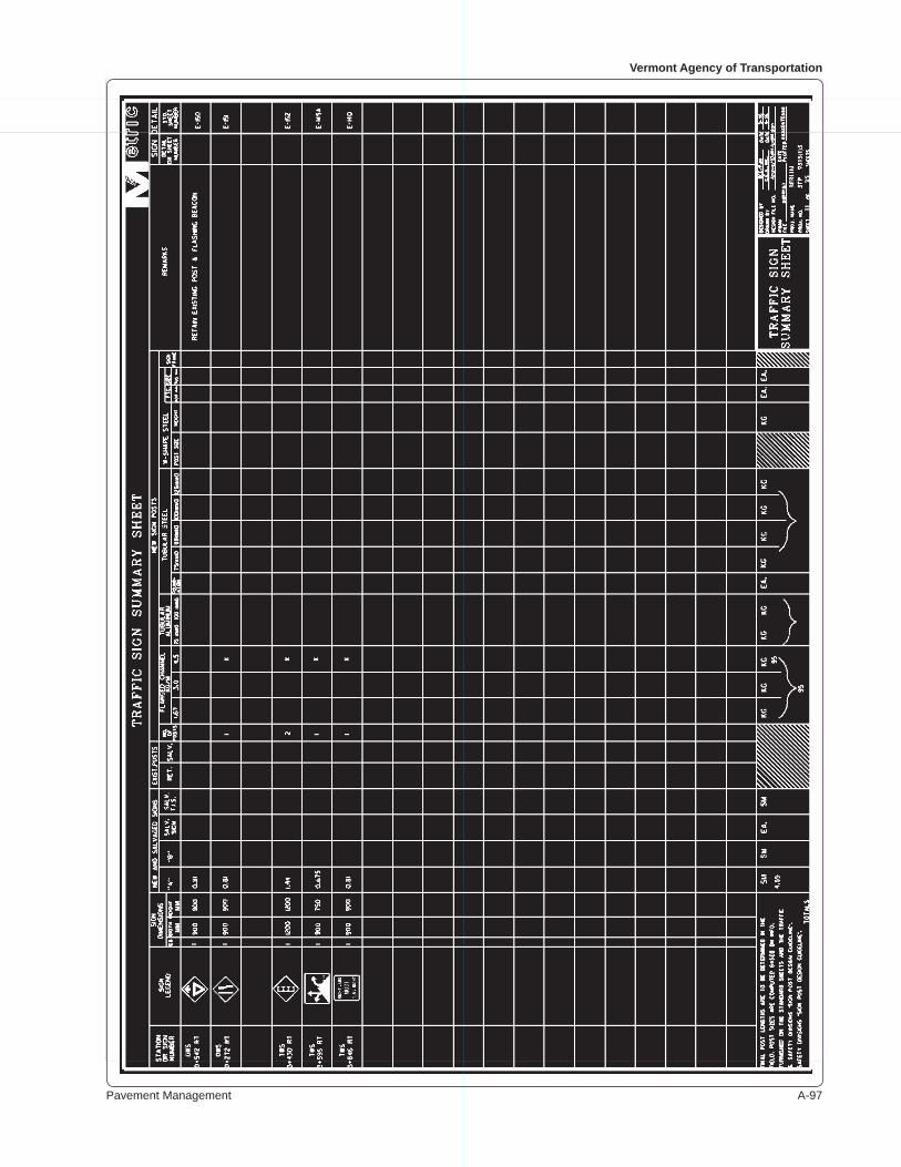
Pavement Management A-��
Vermont Agency of Transportation
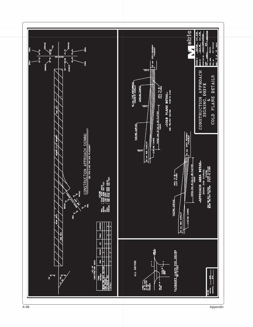
A-�� Appendix

Pavement Management A-��
Vermont Agency of Transportation
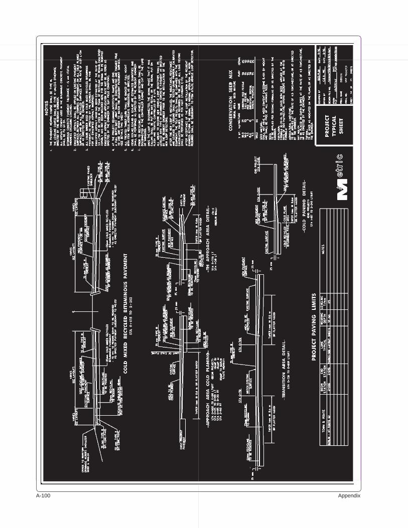
A-�00 Appendix
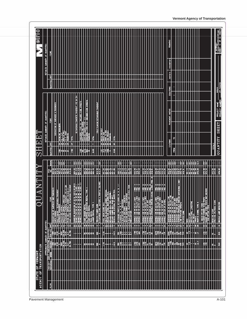
Pavement Management A-�0�
Vermont Agency of Transportation
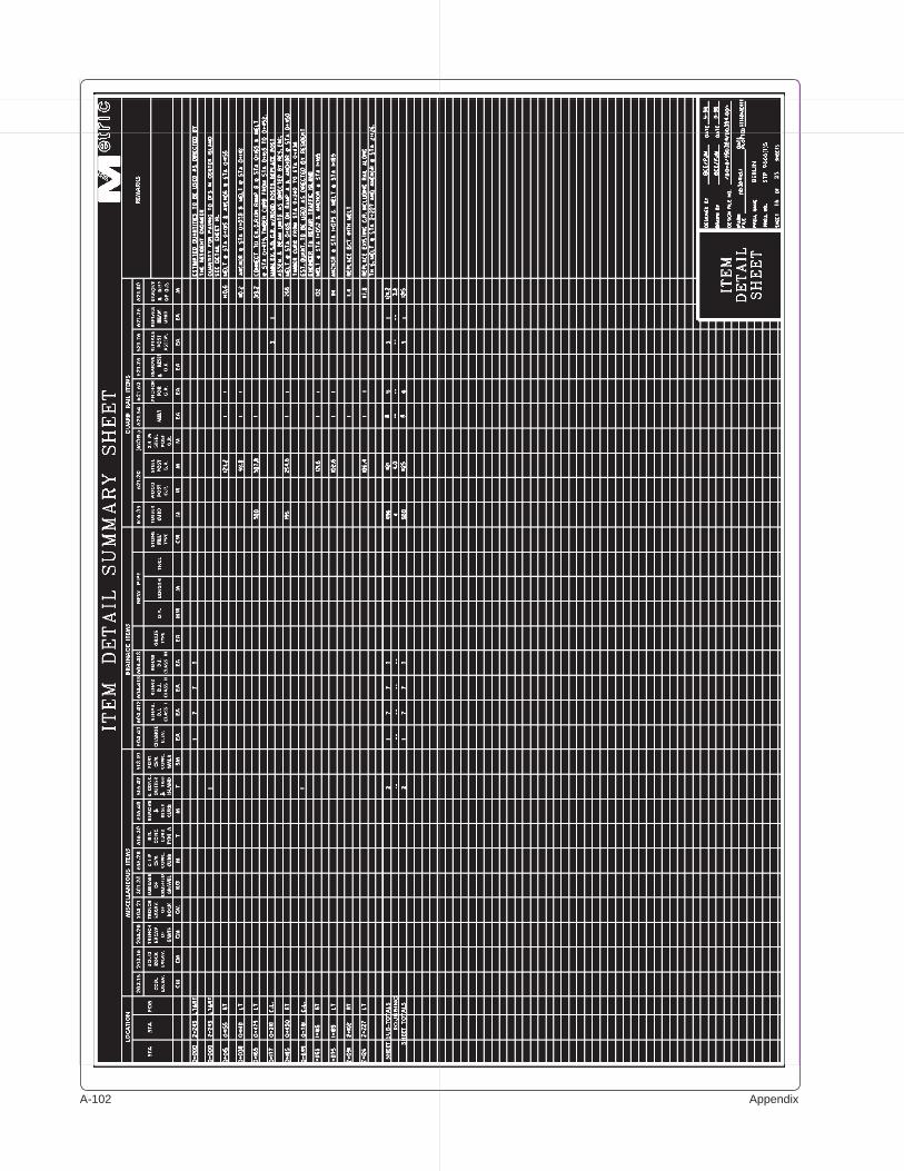
A-�0� Appendix
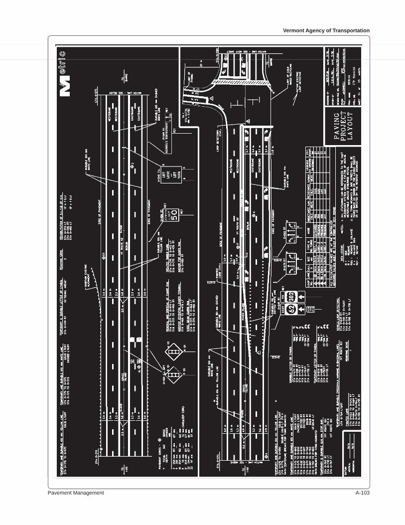
Pavement Management A-�0�
Vermont Agency of Transportation
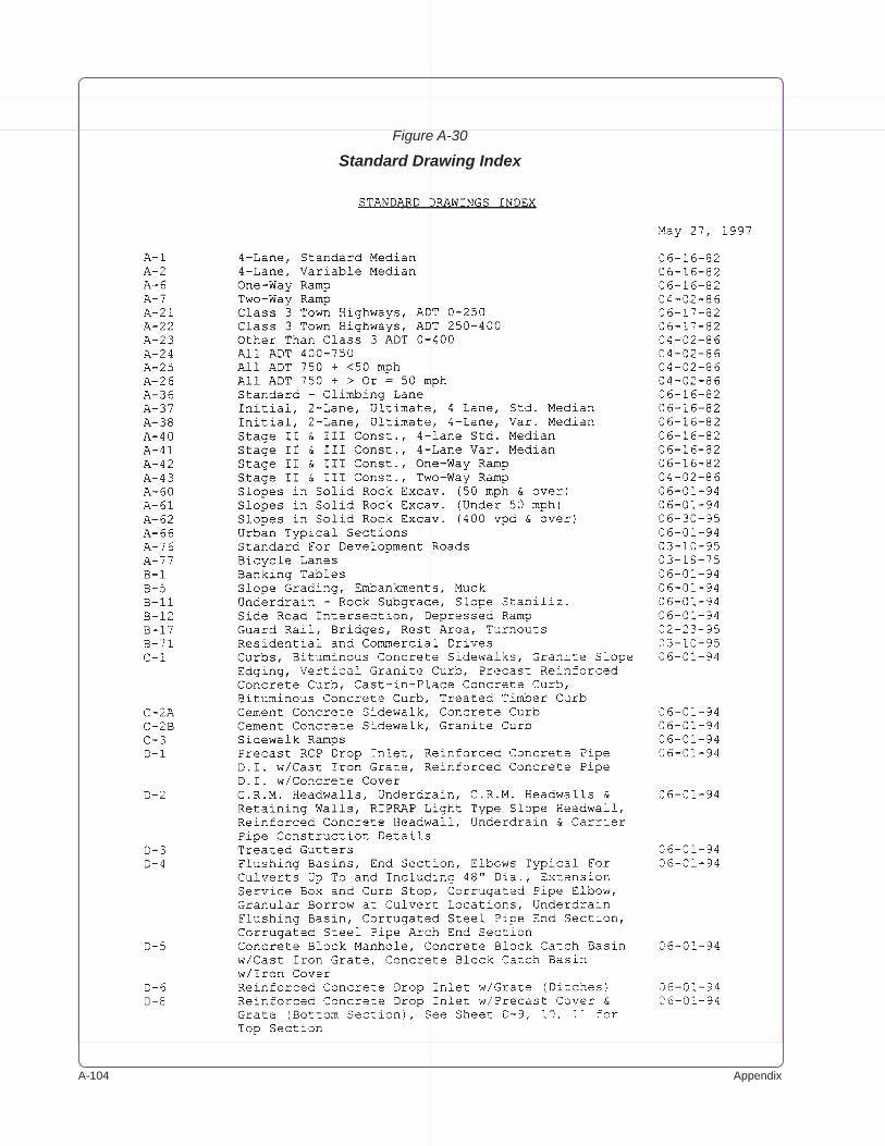
A-�0� Appendix
Figure A-30
Standard Drawing Index

Pavement Management A-�0�
Vermont Agency of Transportation
Figure A-30 (continued)
Standard Drawing Index
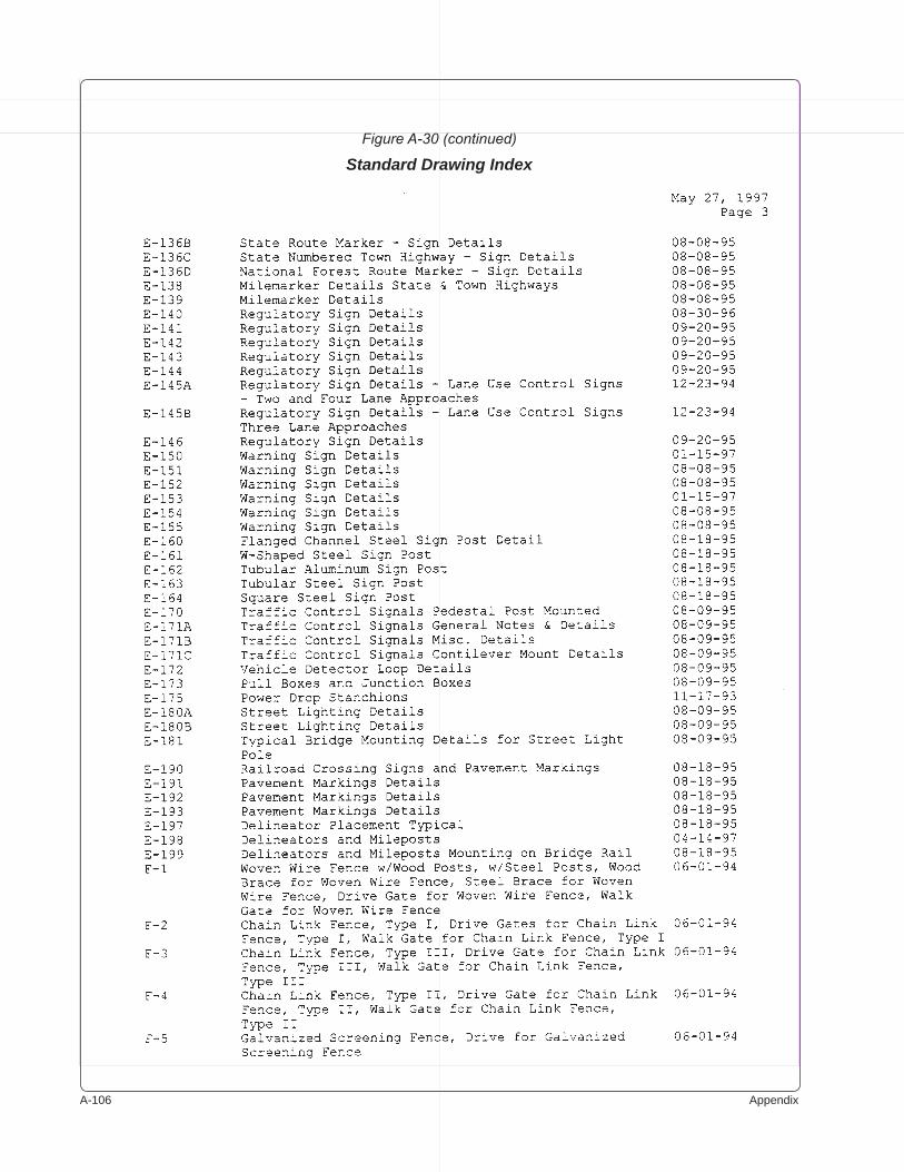
A-�0� Appendix
Figure A-30 (continued)
Standard Drawing Index
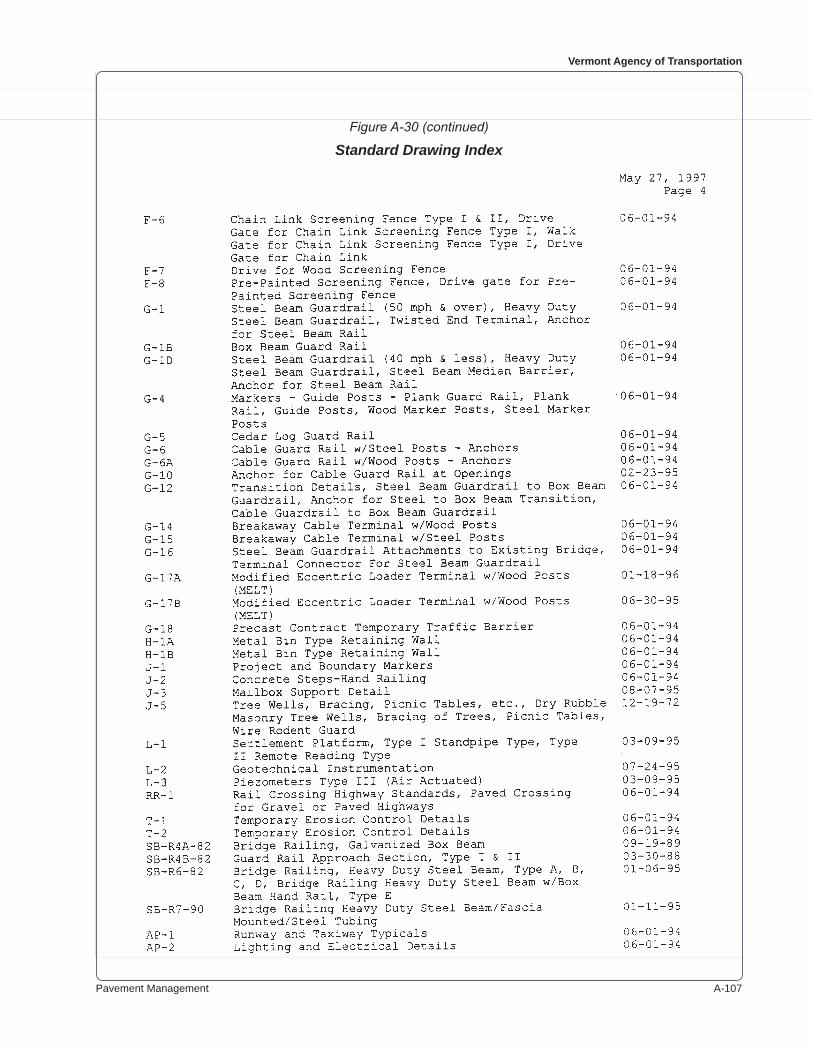
Pavement Management A-�0�
Vermont Agency of Transportation
Figure A-30 (continued)
Standard Drawing Index
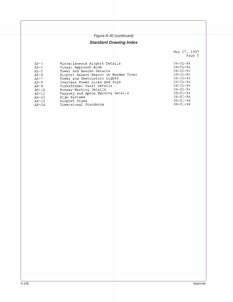
A-�0� Appendix
Figure A-30 (continued)
Standard Drawing Index
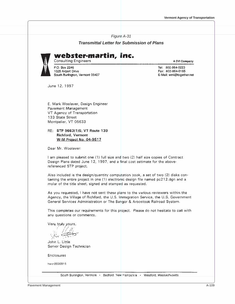
Pavement Management A-�0�
Vermont Agency of Transportation
Figure A-31
Transmittal Letter for Submission of Plans
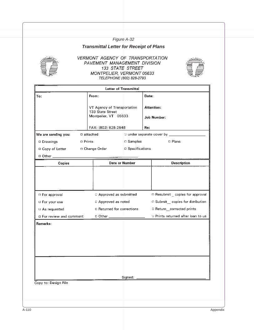
A-��0 Appendix
Figure A-32
Transmittal Letter for Receipt of Plans
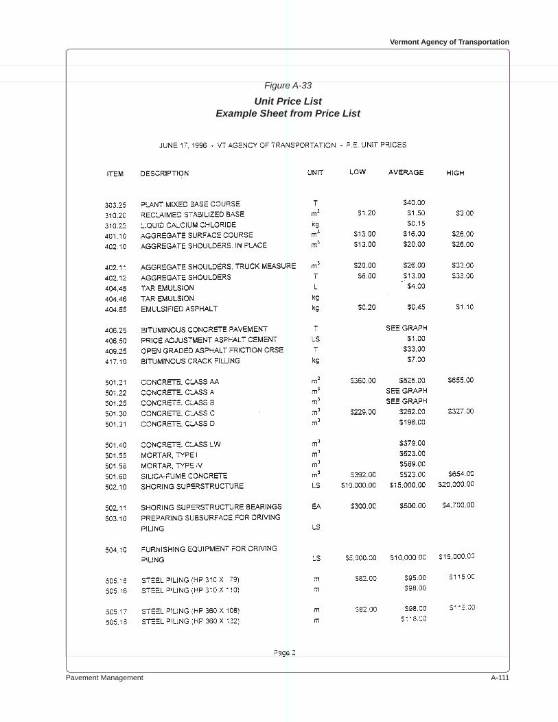
Pavement Management A-���
Vermont Agency of Transportation
Figure A-33
Unit Price ListExample Sheet from Price List
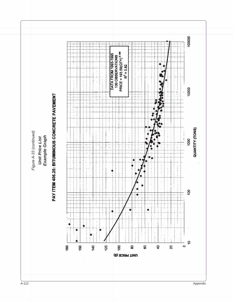
A-��� Appendix
Figu
re A
-33
(con
tinue
d)
Uni
t Pric
e Li
stEx
ampl
e G
raph
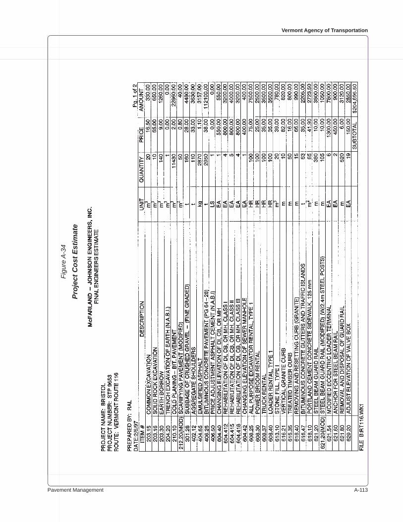
Pavement Management A-���
Vermont Agency of Transportation
Figu
re A
-34
Proj
ect C
ost E
stim
ate
NE

A-��� Appendix
Figu
re A
-34
(con
tinue
d)
Proj
ect C
ost E
stim
ate
N
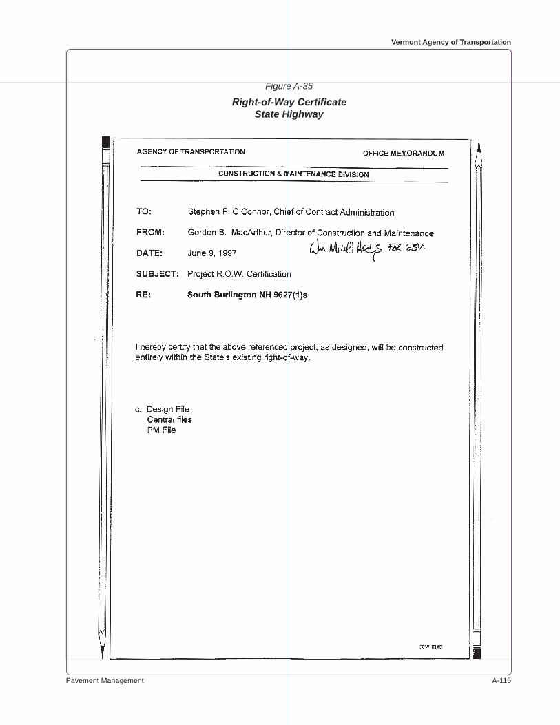
Pavement Management A-���
Vermont Agency of Transportation
Figure A-35
Right-of-Way CertificateState Highway
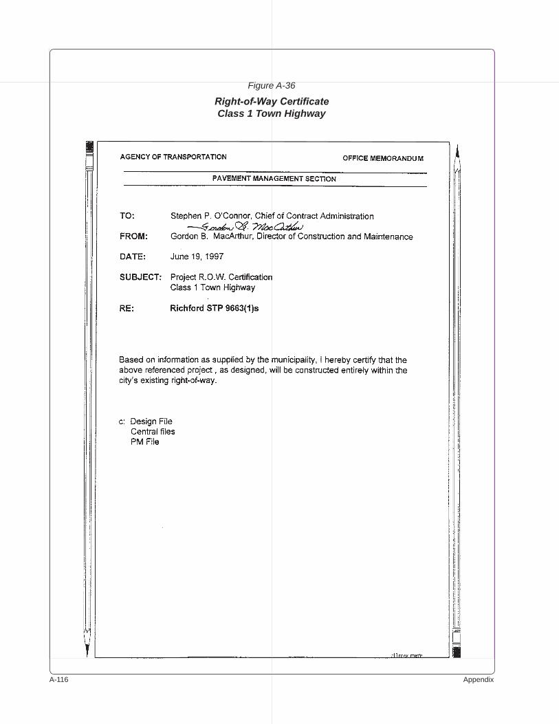
A-��� Appendix
Figure A-36
Right-of-Way CertificateClass 1 Town Highway
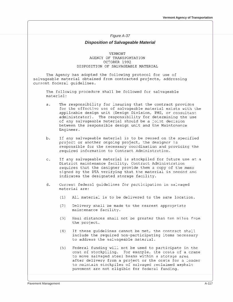
Pavement Management A-���
Vermont Agency of Transportation
Figure A-37
Disposition of Salvageable Material
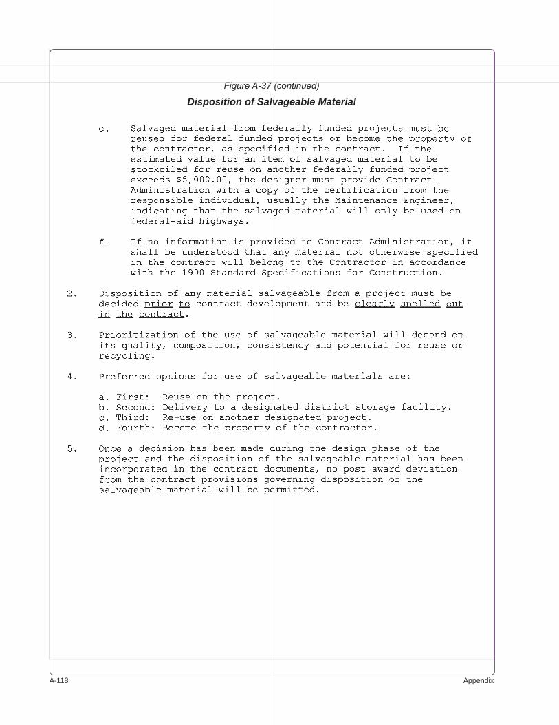
A-��� Appendix
Figure A-37 (continued)
Disposition of Salvageable Material
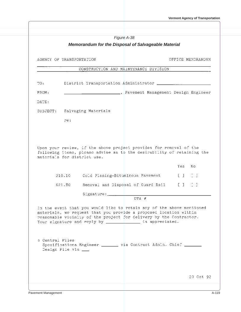
Pavement Management A-���
Vermont Agency of Transportation
Figure A-38
Memorandum for the Disposal of Salvageable Material
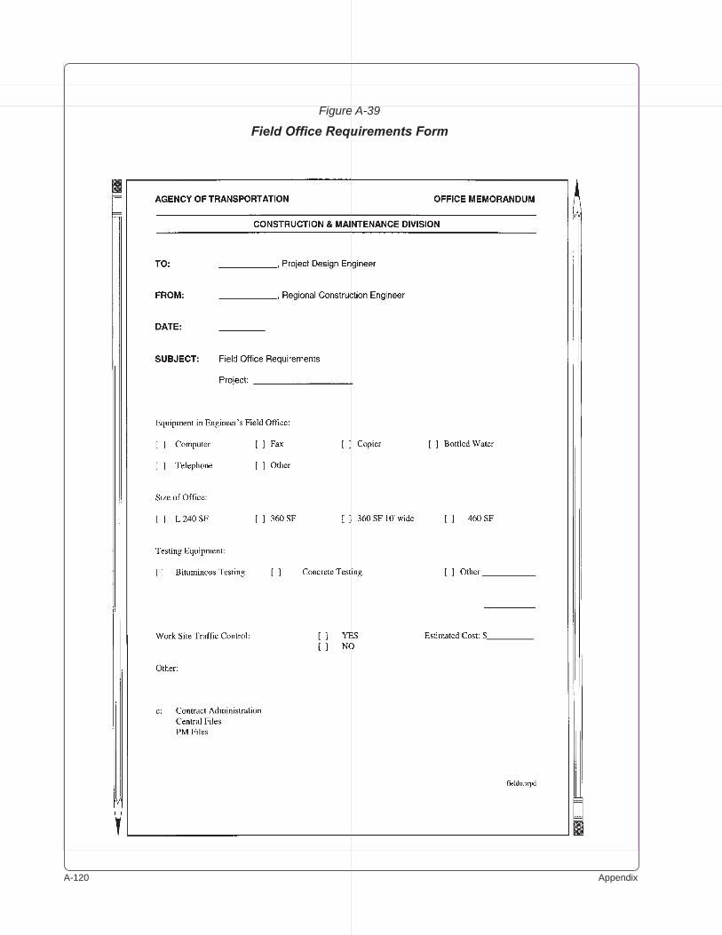
A-��0 Appendix
Figure A-39
Field Office Requirements Form
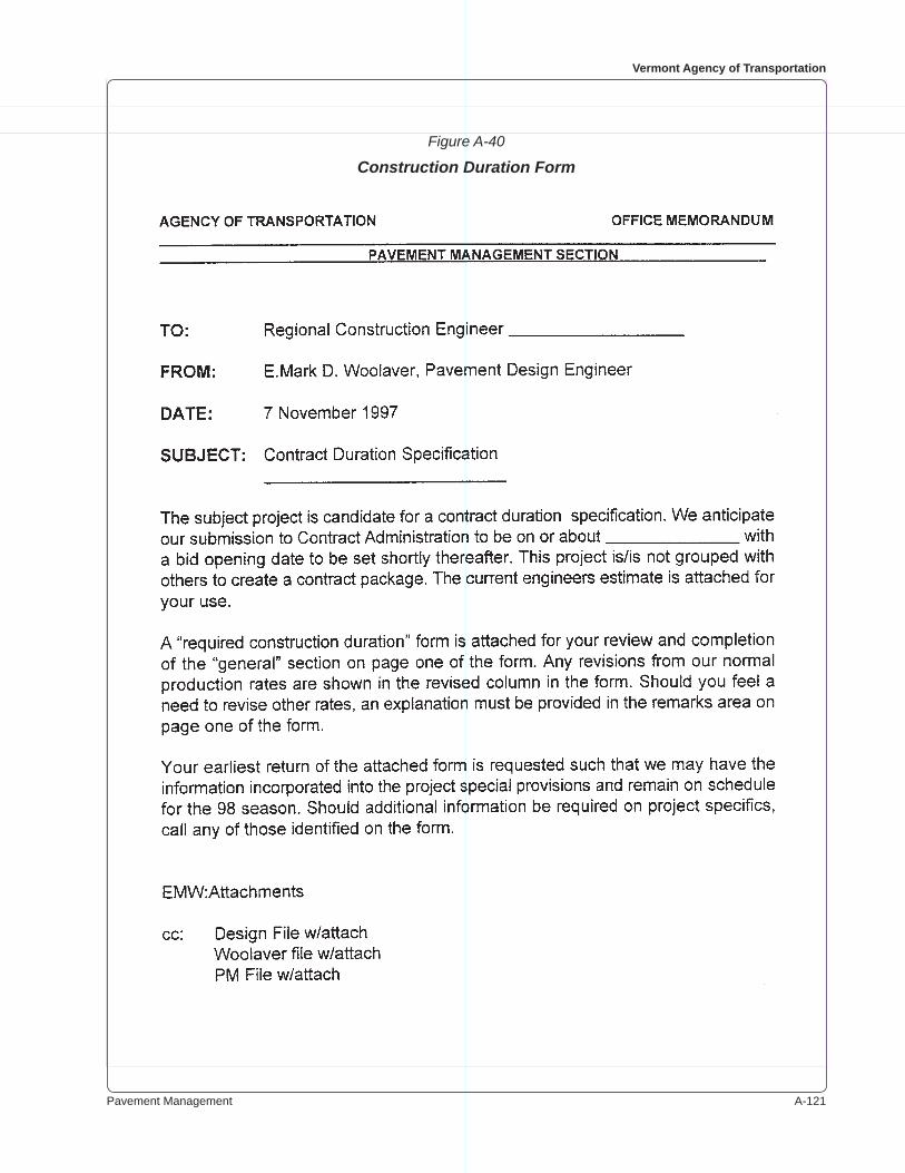
Pavement Management A-���
Vermont Agency of Transportation
Figure A-40
Construction Duration Form
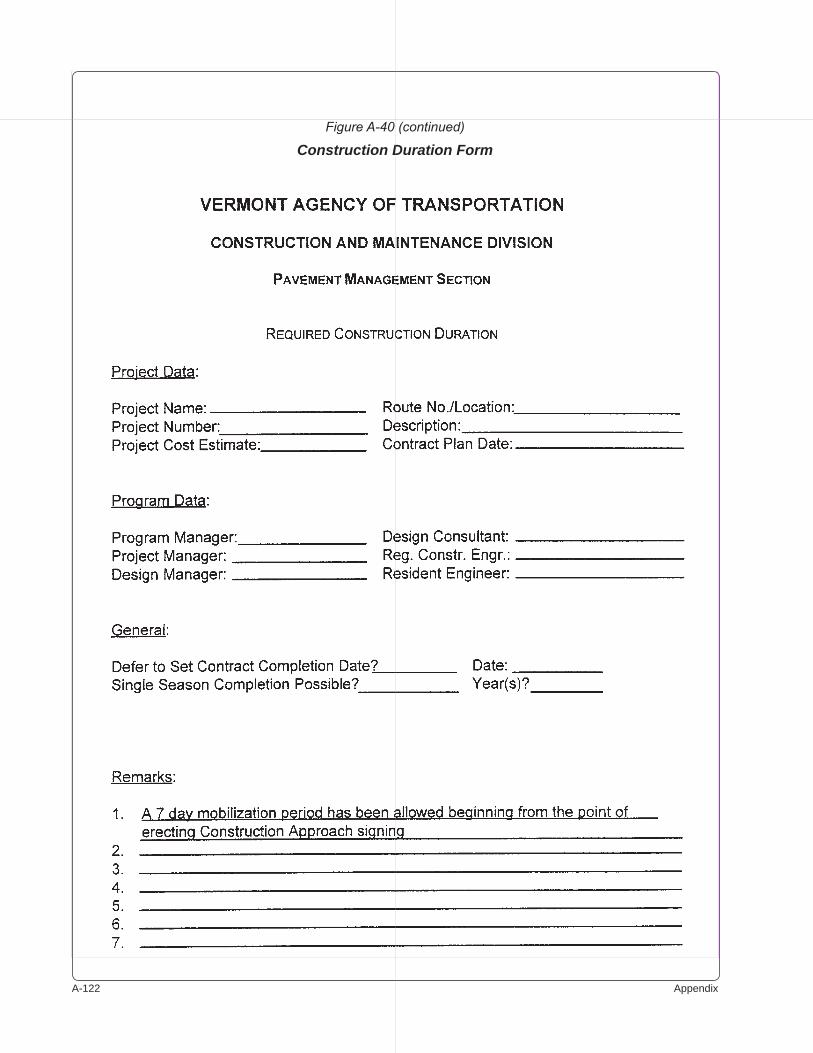
A-��� Appendix
Figure A-40 (continued)
Construction Duration Form
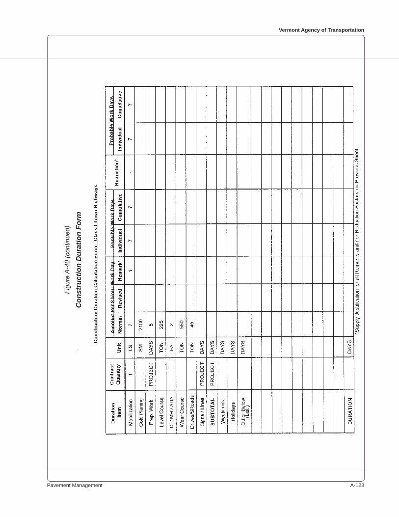
Pavement Management A-���
Vermont Agency of Transportation
Figu
re A
-40
(con
tinue
d)
Con
stru
ctio
n D
urat
ion
Form

A-��� Appendix
Figu
re A
-40
(con
tinue
d)
Con
stru
ctio
n D
urat
ion
Form
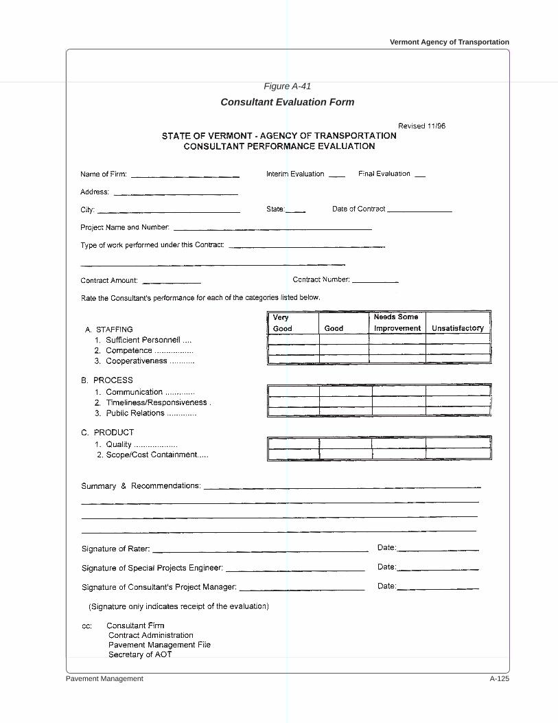
Pavement Management A-���
Vermont Agency of Transportation
Figure A-41
Consultant Evaluation Form
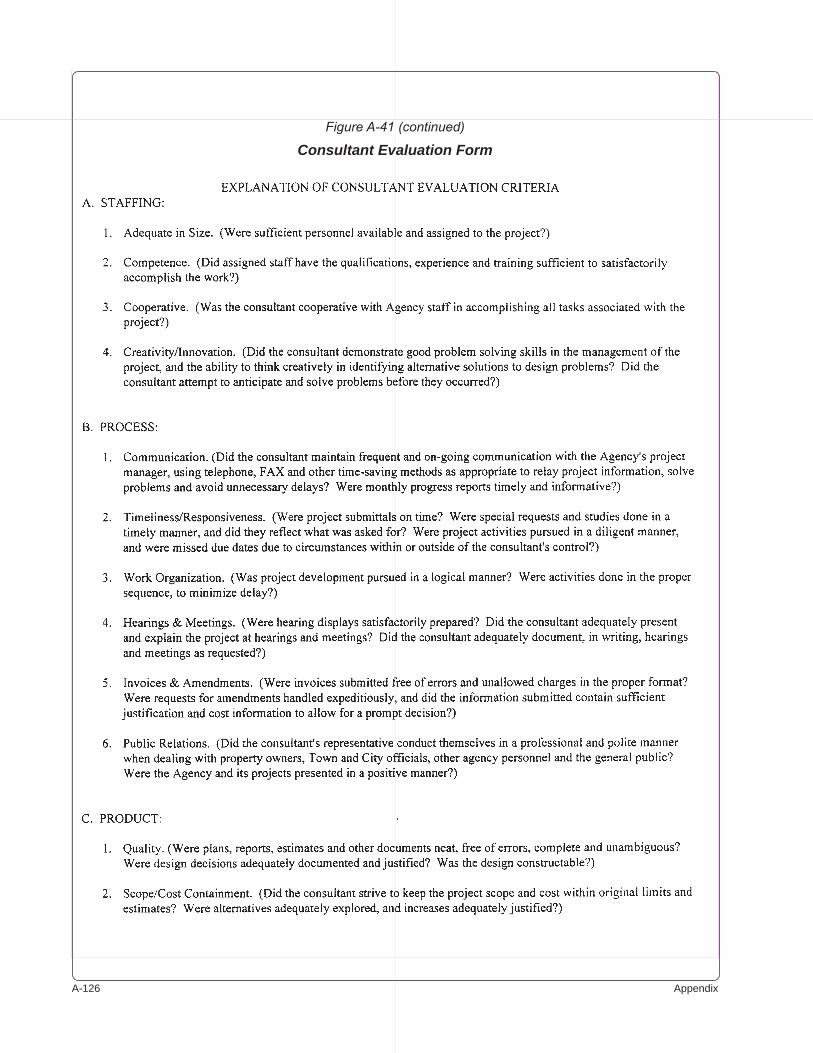
A-��� Appendix
Figure A-41 (continued)
Consultant Evaluation Form

Pavement Management A-���
Vermont Agency of Transportation
Figure A-42
HighEst Estimate
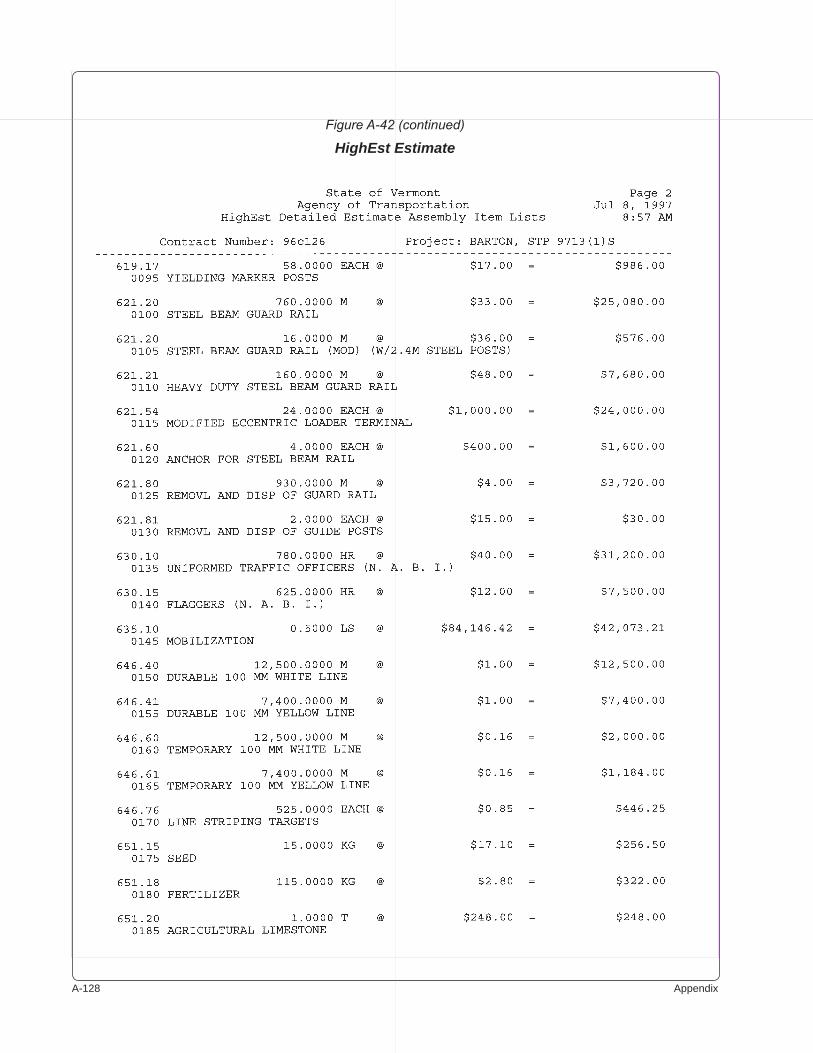
A-��� Appendix
Figure A-42 (continued)
HighEst Estimate
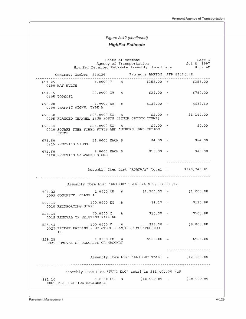
Pavement Management A-���
Vermont Agency of Transportation
Figure A-42 (continued)
HighEst Estimate
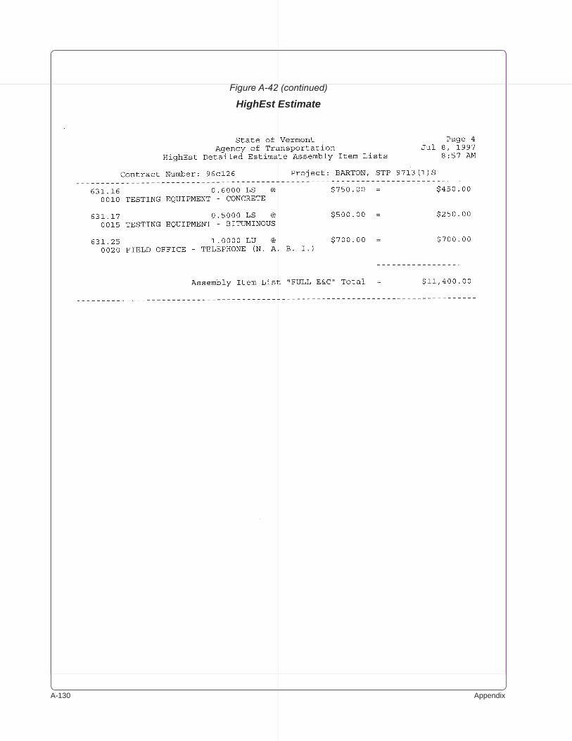
A-��0 Appendix
Figure A-42 (continued)
HighEst Estimate
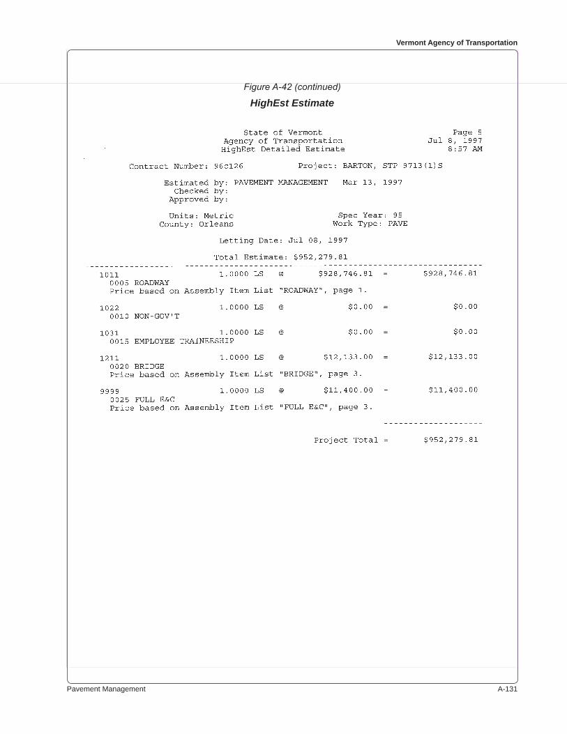
Pavement Management A-���
Vermont Agency of Transportation
Figure A-42 (continued)
HighEst Estimate
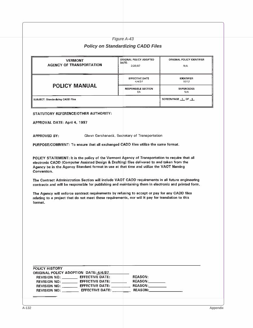
A-��� Appendix
Figure A-43
Policy on Standardizing CADD Files
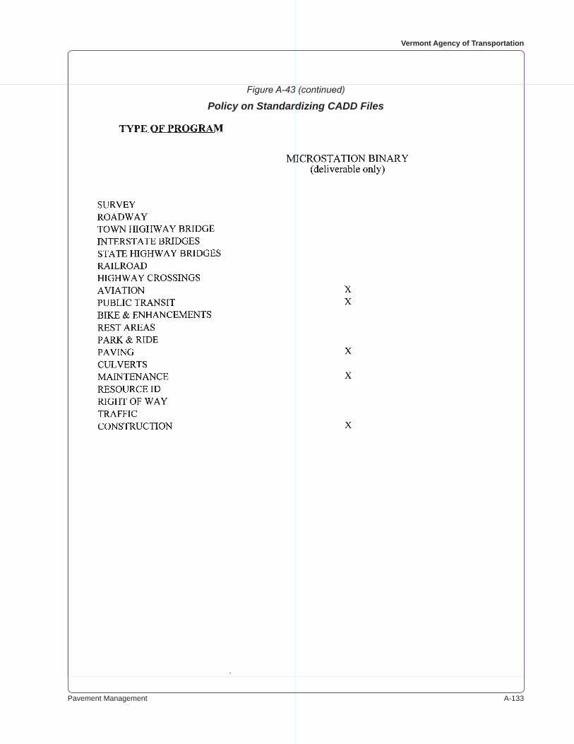
Pavement Management A-���
Vermont Agency of Transportation
Figure A-43 (continued)
Policy on Standardizing CADD Files
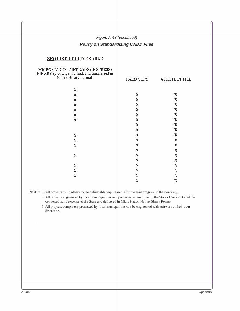
A-��� Appendix
Figure A-43 (continued)
Policy on Standardizing CADD Files
NOTE: 1.Allprojectsmustadheretothedeliverablerequirementsfortheleadprogramintheirentirety. 2.AllprojectsengineeredbylocalmunicipalitiesandprocessedatanytimebytheStateofVermontshallbe
convertedatnoexpensetotheStateanddeliveredinMicroStationNativeBinaryFormat. 3.Allprojectscompletelyprocessedbylocalmunicpalitiescanbeengineeredwithsoftwareattheirown
discretion.
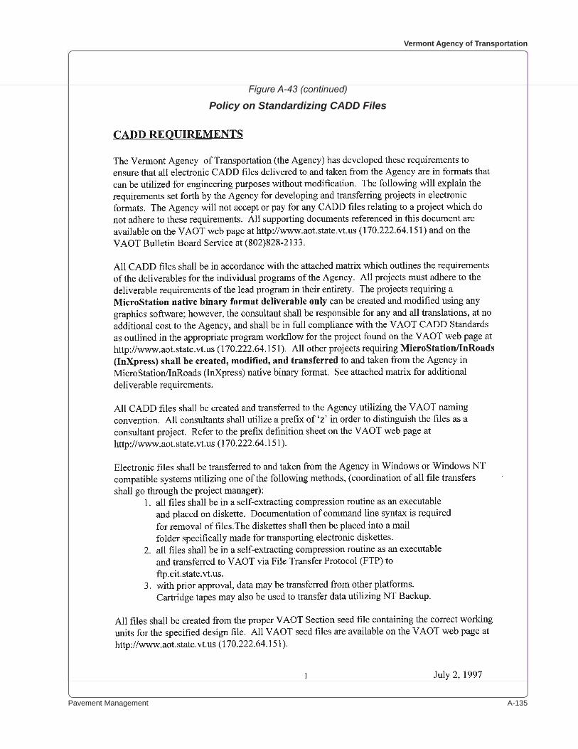
Pavement Management A-���
Vermont Agency of Transportation
Figure A-43 (continued)
Policy on Standardizing CADD Files
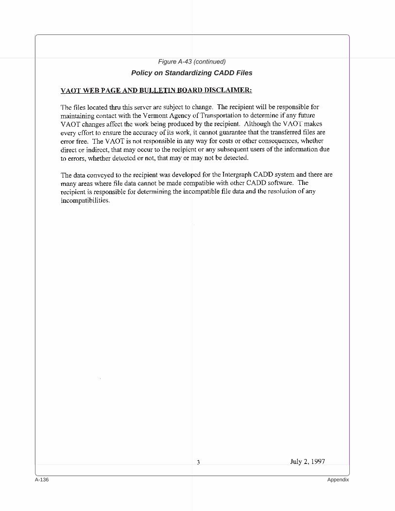
A-��� Appendix
Figure A-43 (continued)
Policy on Standardizing CADD Files
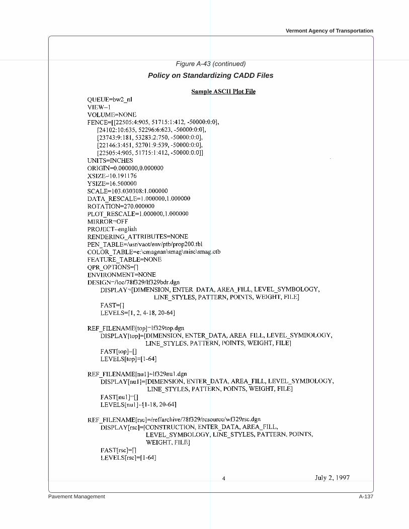
Pavement Management A-���
Vermont Agency of Transportation
Figure A-43 (continued)
Policy on Standardizing CADD Files
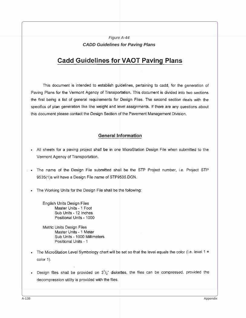
A-��� Appendix
Figure A-44
CADD Guidelines for Paving Plans
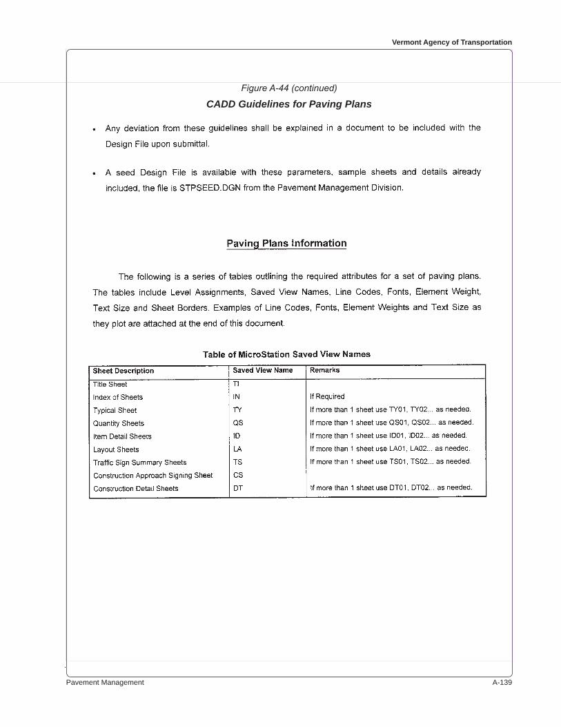
Pavement Management A-���
Vermont Agency of Transportation
Figure A-44 (continued)
CADD Guidelines for Paving Plans
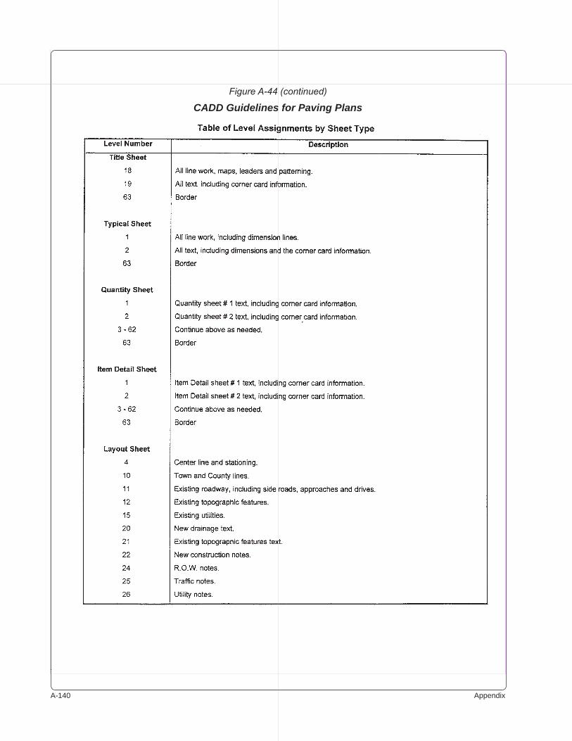
A-��0 Appendix
Figure A-44 (continued)
CADD Guidelines for Paving Plans
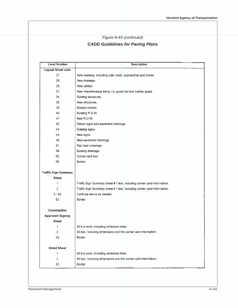
Pavement Management A-���
Vermont Agency of Transportation
Figure A-44 (continued)
CADD Guidelines for Paving Plans
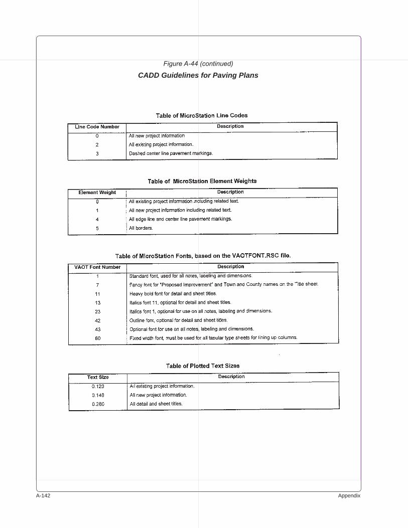
A-��� Appendix
Figure A-44 (continued)
CADD Guidelines for Paving Plans

Pavement Management A-���
Vermont Agency of Transportation
Figure A-44 (continued)
CADD Guidelines for Paving Plans
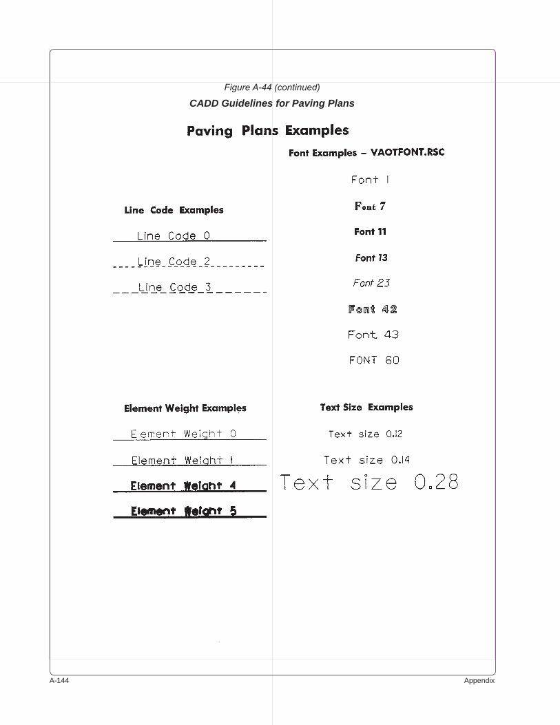
A-��� Appendix
Figure A-44 (continued)
CADD Guidelines for Paving Plans

Pavement Management A-���
Vermont Agency of Transportation
Figure A-44 (continued)
CADD Guidelines for Paving Plans
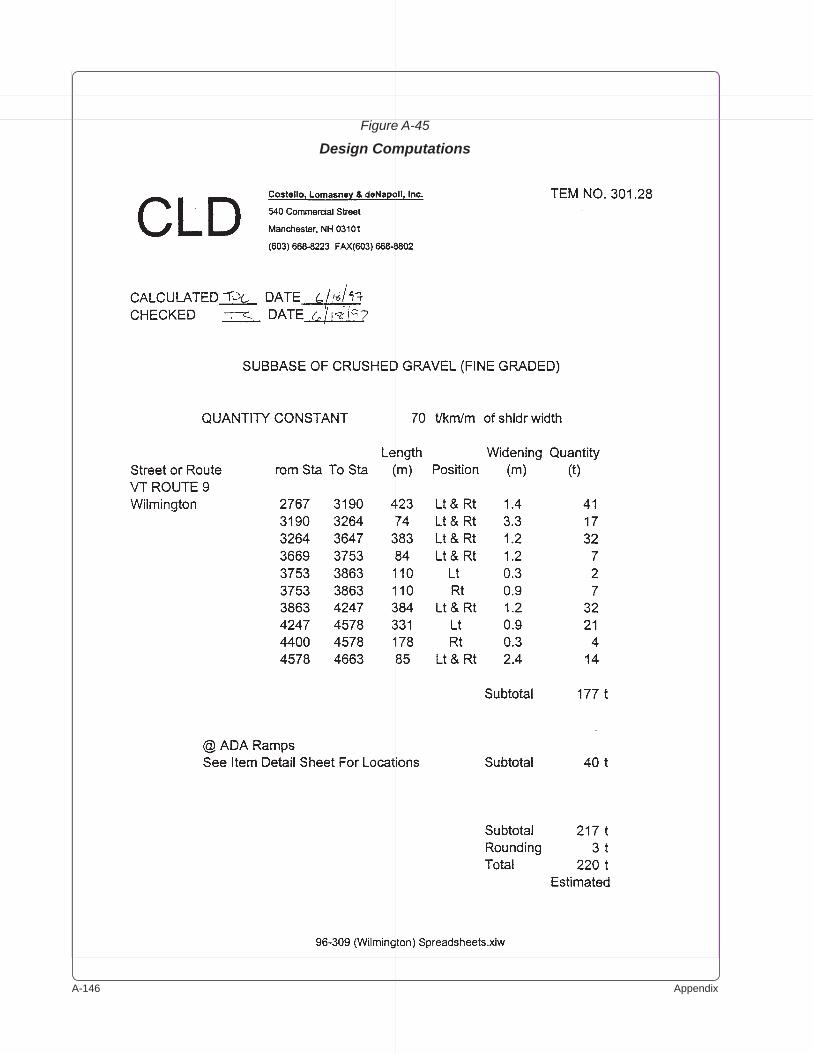
A-��� Appendix
Figure A-45
Design Computations
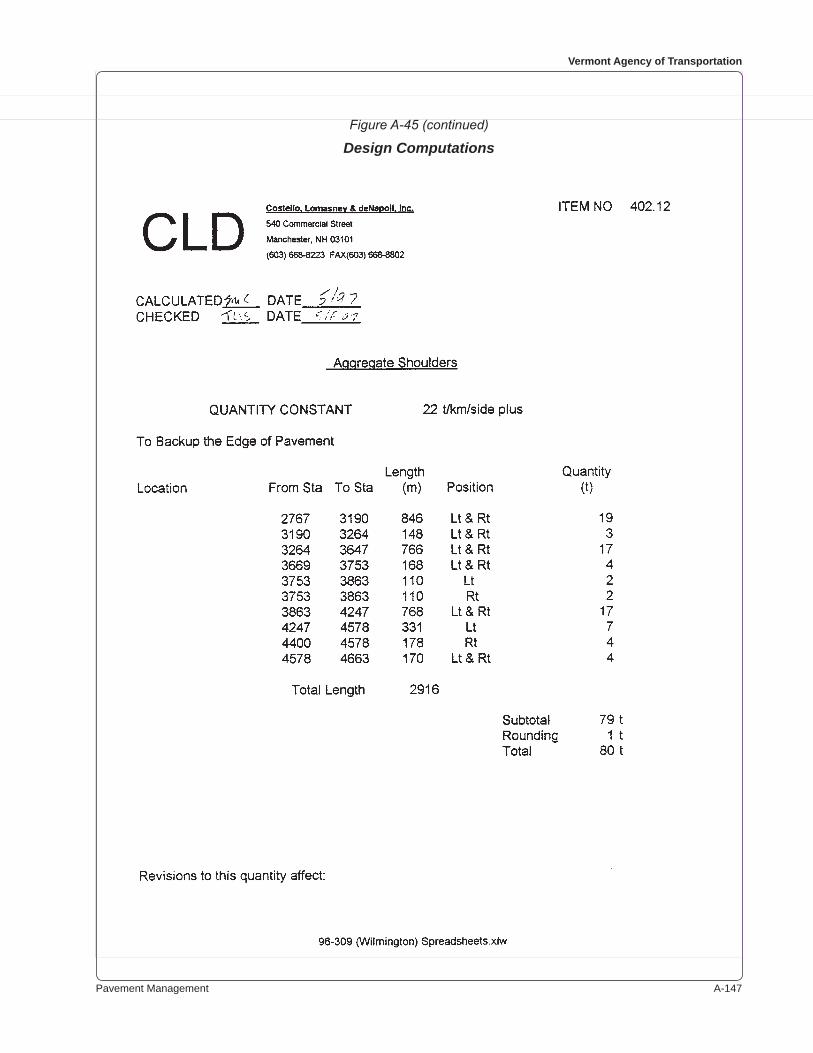
Pavement Management A-���
Vermont Agency of Transportation
Figure A-45 (continued)
Design Computations
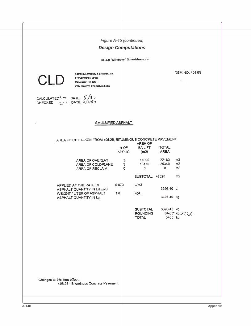
A-��� Appendix
Figure A-45 (continued)
Design Computations
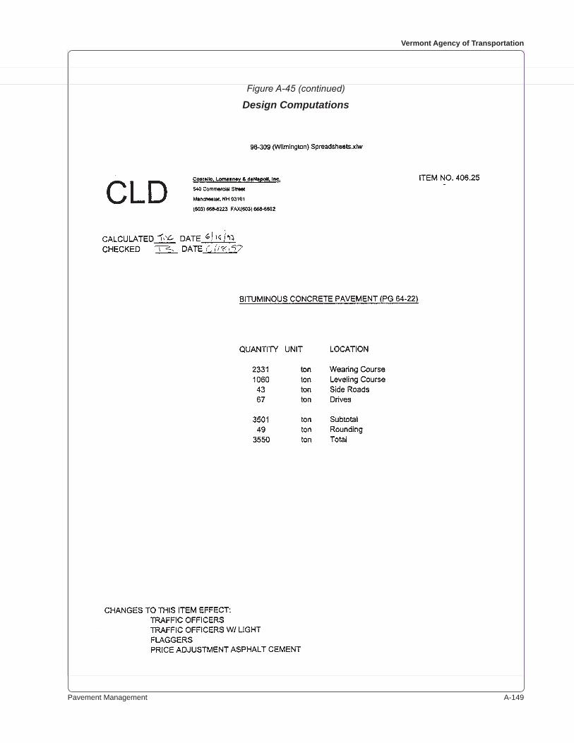
Pavement Management A-���
Vermont Agency of Transportation
Figure A-45 (continued)
Design Computations

A-��0 Appendix
Figure A-45 (continued)
Design Computations
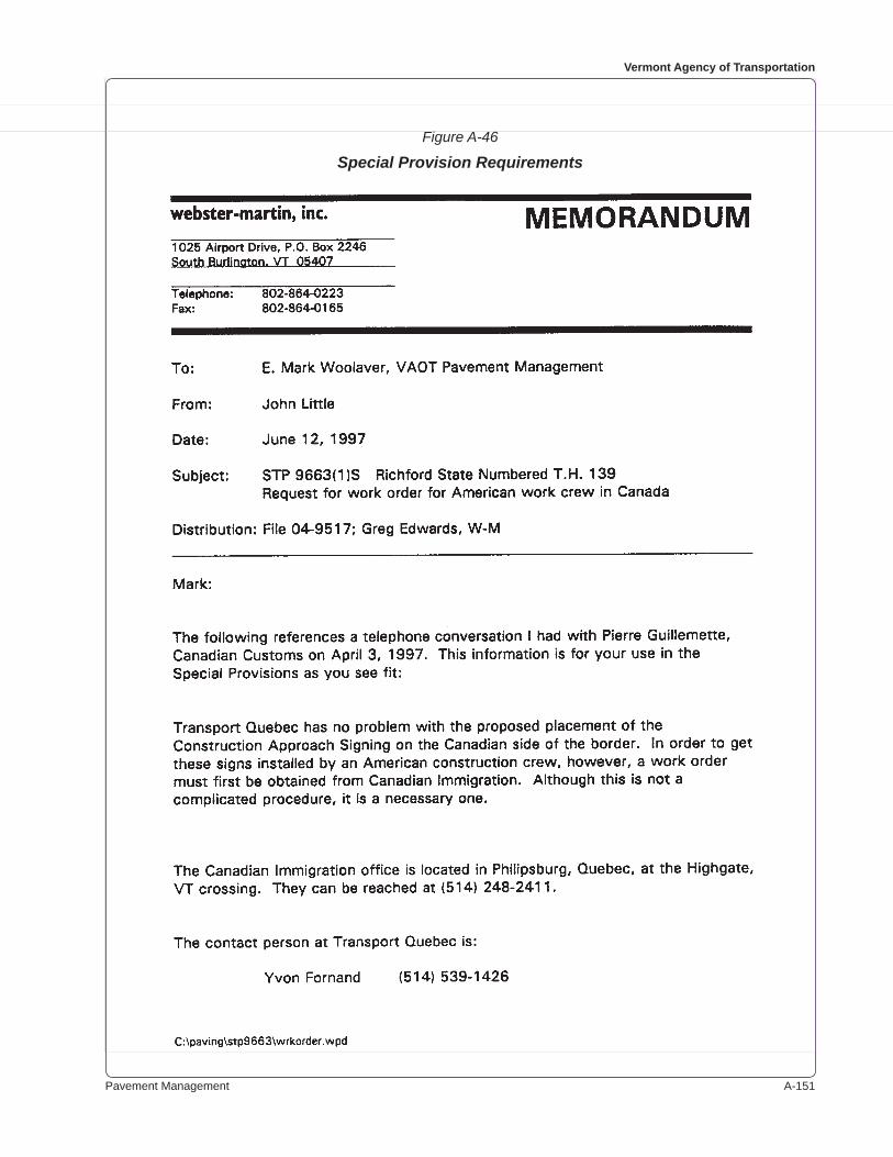
Pavement Management A-���
Vermont Agency of Transportation
Figure A-46
Special Provision Requirements
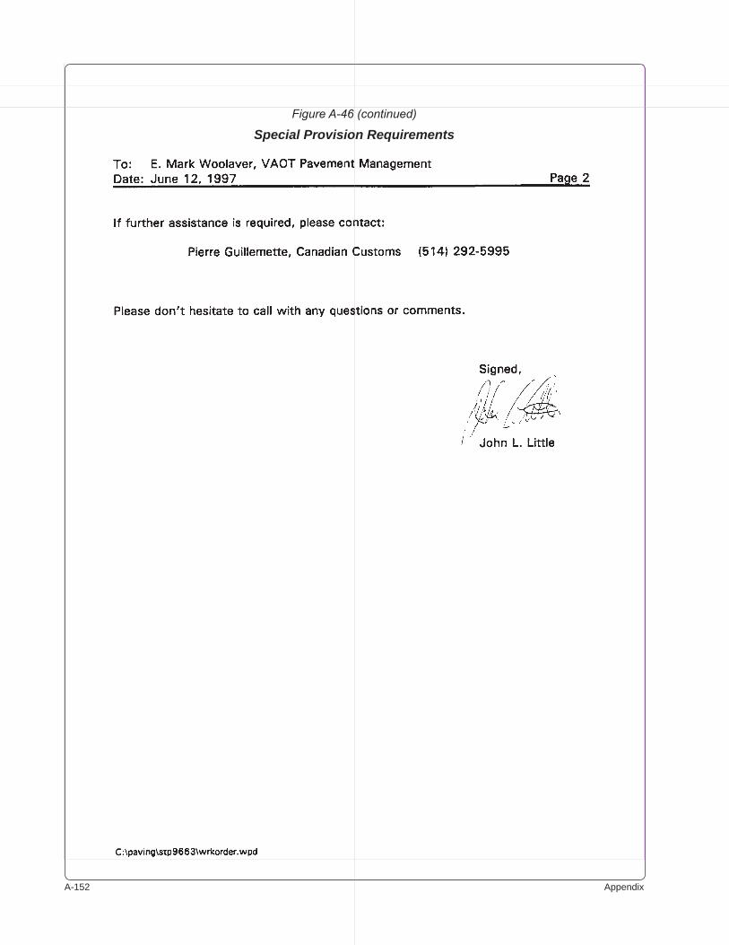
A-��� Appendix
Figure A-46 (continued)
Special Provision Requirements
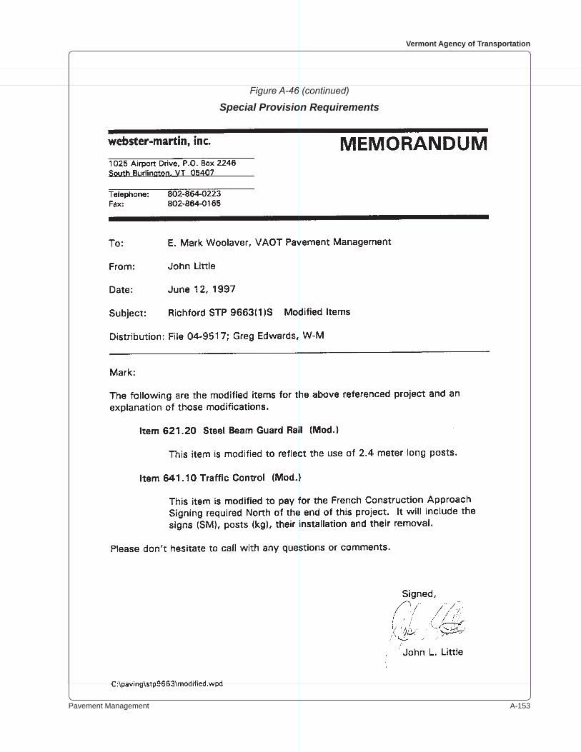
Pavement Management A-���
Vermont Agency of Transportation
Figure A-46 (continued)
Special Provision Requirements
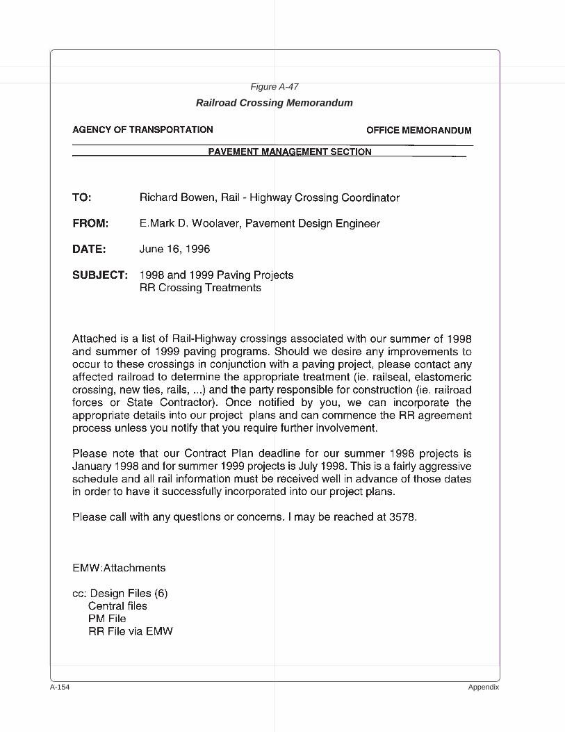
A-��� Appendix
Figure A-47
Railroad Crossing Memorandum
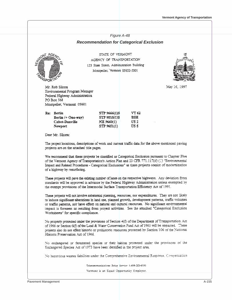
Pavement Management A-���
Vermont Agency of Transportation
Figure A-48
Recommendation for Categorical Exclusion
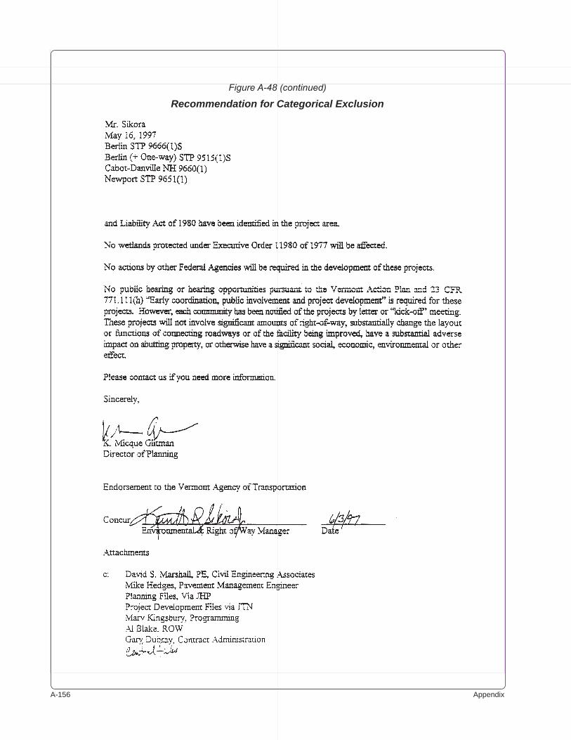
A-��� Appendix
Figure A-48 (continued)
Recommendation for Categorical Exclusion

Pavement Management A-���
Vermont Agency of Transportation
Figure A-49
Transmittal Request for Prints
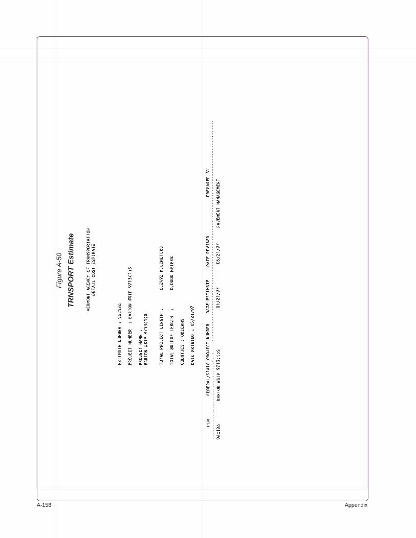
A-��� Appendix
Figu
re A
-50
TRN
SPO
RT
Estim
ate
Pavement Management A-���
Vermont Agency of Transportation
Figu
re A
-50
(con
tinue
d)
TRN
SPO
RT
Estim
ate
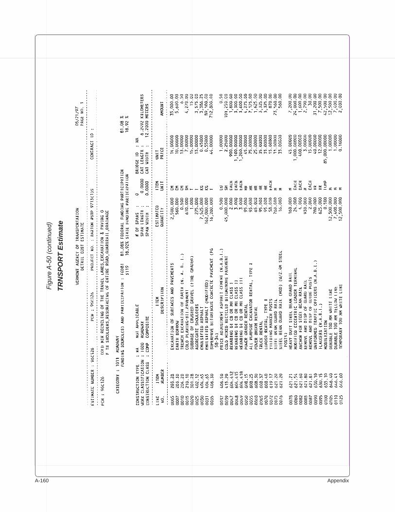
A-��0 Appendix
Figu
re A
-50
(con
tinue
d)
TRN
SPO
RT
Estim
ate
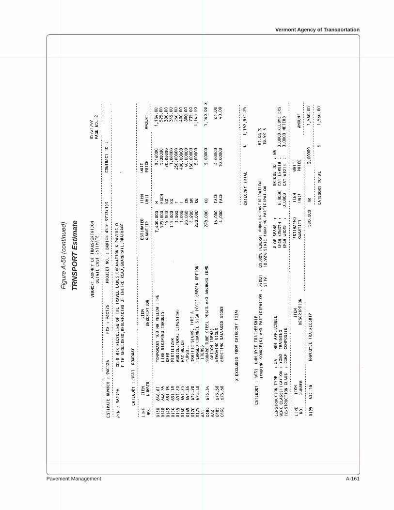
Pavement Management A-���
Vermont Agency of Transportation
Figu
re A
-50
(con
tinue
d)
TRN
SPO
RT
Estim
ate
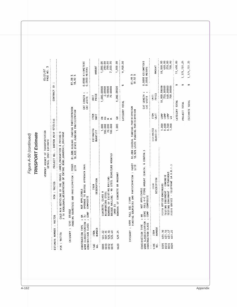
A-��� Appendix
Figu
re A
-50
(con
tinue
d)
TRN
SPO
RT
Estim
ate
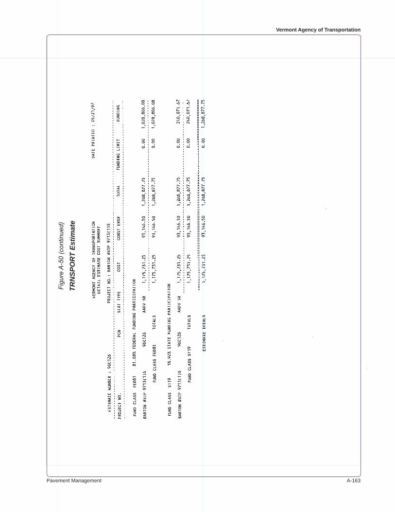
Pavement Management A-���
Vermont Agency of Transportation
Figu
re A
-50
(con
tinue
d)
TRN
SPO
RT
Estim
ate
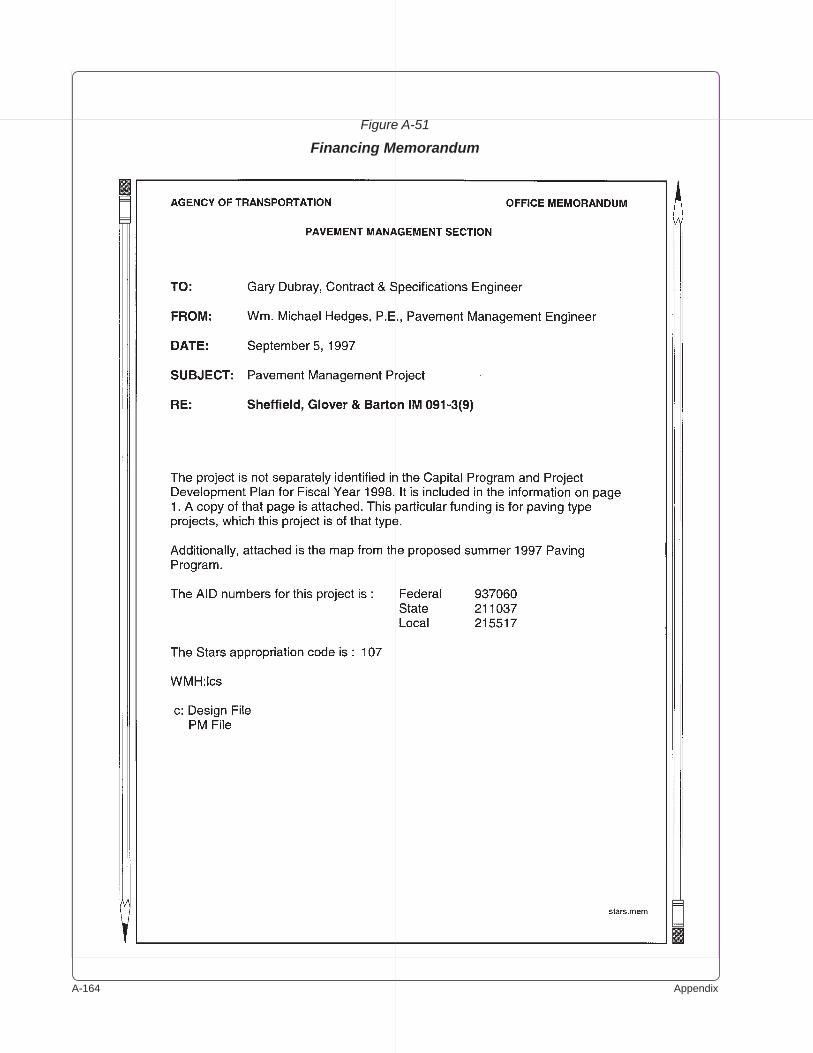
A-��� Appendix
Figure A-51
Financing Memorandum
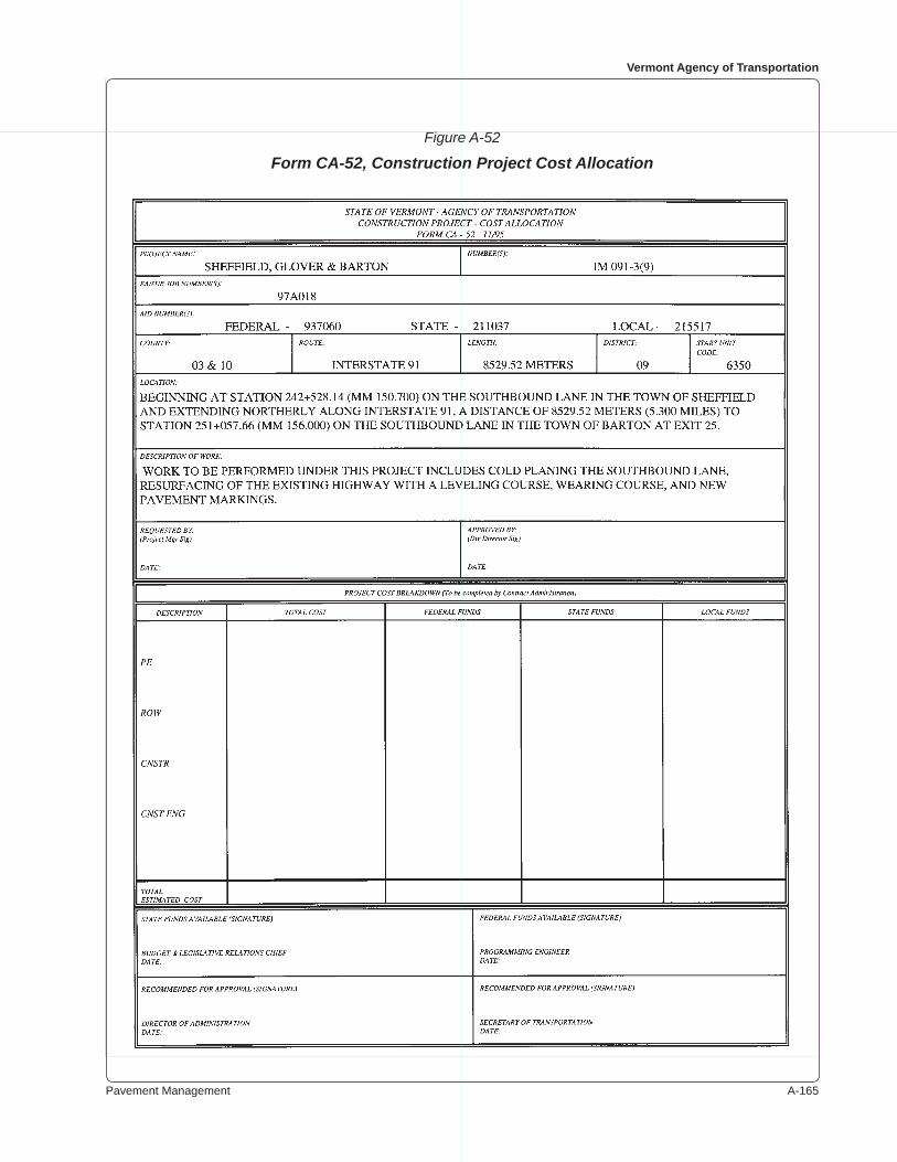
Pavement Management A-���
Vermont Agency of Transportation
Figure A-52
Form CA-52, Construction Project Cost Allocation

A-��� Appendix
Figure A-53
Project Advertising Memorandum
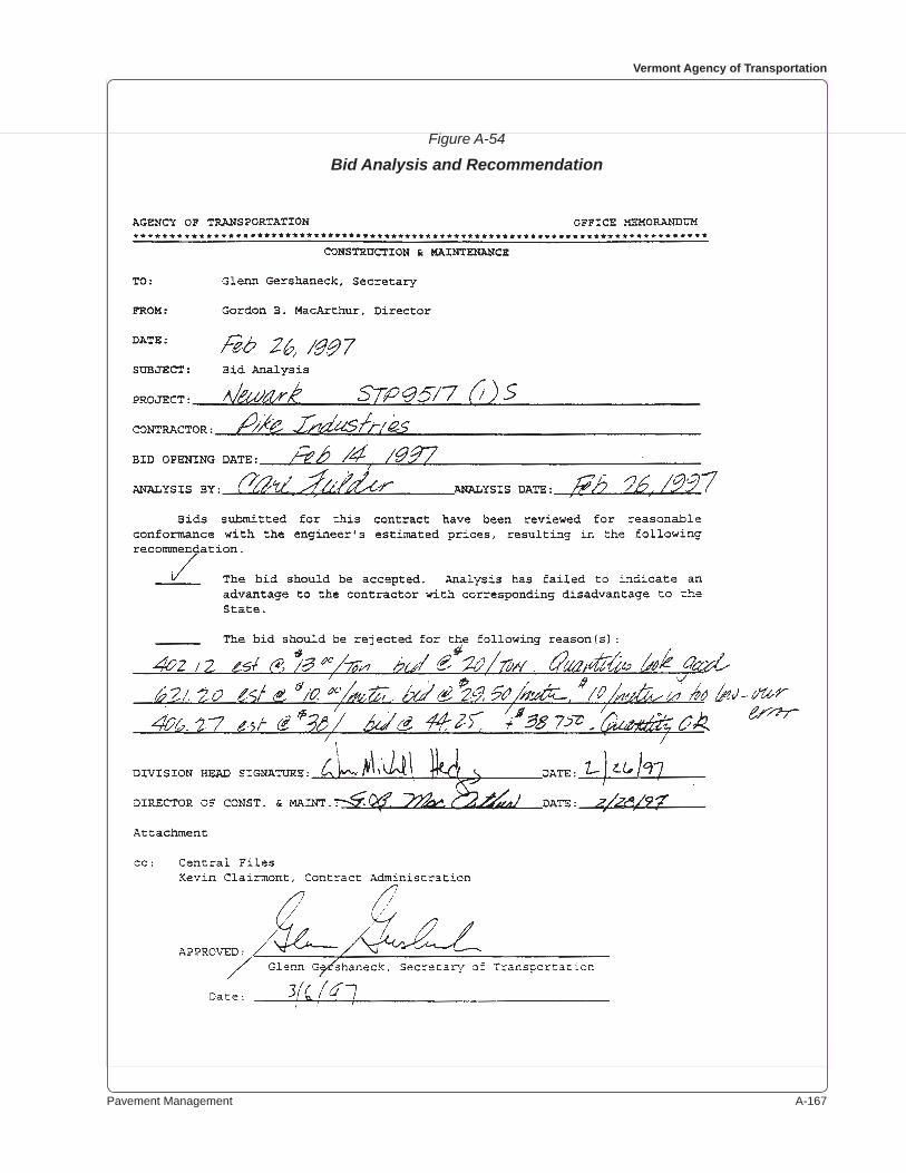
Pavement Management A-���
Vermont Agency of Transportation
Figure A-54
Bid Analysis and Recommendation

A-��� Appendix
Pavement Management
VERMONT AGENCY OF TRANSPORTATIONVERMONT AGENCY OF TRANSPORTATION
BlankIndex
AAASHTO, Guide for Design of Pavement Structures 3-15Americans with Disabilities Act (ADA) (see plans, ADA
ramps; plans, layout sheets; project design, scope definition, ADA)
annual report (see network, annual report)
CCADD
file name 7-5(see also design)
categorical exclusion 7-4, 7-6document 7-4requesting 5-13 (see also FHWA, environmental permitting; project
design)certification acceptance 6-4channelization (see plans, channelization)clear zones (see plans)composite project 7-1 (see also plans)conceptual list of projects 3-2, 3-3, 3-11, 3-12consultants
management of 1-2, 1-4(see also design; contracting, design)
constructionproblems 1-6, 6-4, 8-1, 8-2, 8-3, 9-5quality 1-3, 1-6, 6-2, 6-3, 6-4, 8-2 specifications 6-3, 7-2, 7-6, 9-7, 9-8
construction phaseconstruction section role 2-3, 2-6, 8-1, 8-2, 8-3, 8-4decisions 8-2feedback 6-1, 6-2, 8-3project scope, section role 8-1resident engineer role 6-1, 6-4, 8-1, 8-2, 8-3, 8-4
construction problems (see construction)Contract Administration
advertising proposal 7-6, 7-7bid analysis 7-8bid opening 7-8bid proposal 7-6, 7-7contract package 7-6, 7-7contract plans 5-12contract special provisions 7-4, 7-6, 7-7finance and maintenance agreement 4-6railroad agreement 4-7special provisions 5-14TRNSPORT estimate 7-5utility agreement 4-7
contract completion date (see plans)contract duration, requesting 5-14contracting
condition inspection 1-2, 1-3, 2-6, 3-7construction 6-3, 7-1, 7-6, 7-7design 1-2, 1-3, 1-4, 3-18, 5-1, 5-2, 6-2, 6-3
control data block 5-5 (see also project plans, title sheet)conventional symbols (see project plans)coordination
during project plan development 5-14during project definition 4-8
coringequipment 3-15investigation 3-15
corner card (see project plans)cost estimate
contract estimate 7-3, 7-5, 7-8engineer’s estimate 5-12preliminary project 3-13(see also HighEst estimate)
crack fillingflush-filling 9-6over-banding 9-6materials 9-6, 9-7preparation 9-6

Index
crack filling (continued)projects (see program of projects)service life 9-6specifications for contracting 9-7
crack sealing 9-6, 9-7cracks
at cold joints 6-4, 9-5, 9-6filling 9-5, 9-6reflective 9-4, 9-5, 9-8sealing 9-4, 9-5
curbaffecting treatment 3-9on item detail sheet 5-9(see also treatment )
DDARWIN
overlay design 3-15overlay design software 3-15, 3-19
DesignCADD information provided to designer 5-2 CADD seed file 5-2 (see also CADD)consultant selection 5-1, 5-2consultant scope of work, 5-1cost control, 6-2data for project definition, 4-2ESALs 3-7, 4-2exception to guidelines 4-2, 4-5, 6-3, 6-4folder 5-2
list of contents 4-2goal of 7-1guidelines, list of 4-1guidelines for bridges 4-5project information to designer 4-2, 5-2project location and description 5-4recommendation 4-3 (see also overlay recommenda-
tion)standards 4-1work flow, spreadsheet 5-2year 5-5
dipstick (profilometer) 2-3, 3-15ditches (see project plans)drainage (see project design, scope definition; project
plans)
EELMOD, pavement design software 3-15edge breakup (see maintenance, indicators)employee training, during construction 5-14engineer’s estimate (see cost estimate)environmental permits (see categorical exclusion)ESALs, design 4-3
Ffalling weight deflectometer 3-15 (see also FWD)FHWA
approval of categorical exclusion required 5-13approval of design exception required 4-2environmental permitting role 4-6oversight role 6-4 publications 1-6, 3-7, 9-4
field office (see project plans)final plans (see project plans)finance and maintenance agreement 3-18, 4-6 (see also
Contract Administration)flush-filling (see crack filling)funding, paving program 1-4FWD
investigation practice 2-3, 3-15(see also falling weight deflectometer)
Ggore transitions 5-10graphics 7-4, 7-5guardrail (see project design, scope definition)
Hhigh accident location, treatment (see policy; project
design)HighEst estimate 7-3, 7-5
Iindex of sheets (see project plans)Interim Policy on Resurfacing (see policy)intermediate list 3-14, 3-17item detail sheet (see project plans)
Llane tapers (see project plans)layout sheet (see plans)level of improvement (LOI)
concept 2-1, 3-17exceptions 2-2, 3-3, 3-16, 3-17policy 3-3
Mmaintenance
district responsibility 3-13, 9-1, 9-2, 9-3indicators 9-1preventive 6-2, 9-1, 9-3, 9-4preventive program goal 2-2
research on 2-3, 9-4responsibility 1-6, 9-3treatments 2-2, 9-3, 9-4
Pavement Management
Vermont Agency of Transportation
programs 9-3restorative 9-1, 9-3
Manual on Uniform Traffic Control Devices (MUTCD) 4-4 (see also project design, scope definition)
mapping 2-5, 2-7
Nnetwork
analysis 2-1, 2-3, 2-4, 2-6, 2-7, 3-9steps 2-6
annual report 1-6, 2-7content 2-7distribution 2-8
condition, pavementcracking 3-7, 3-8database 2-4, 2-5, 3-7, 3-10patching 3-8ride quality 3-8rutting 3-7, 3-8skid resistance 2-3, 3-8
condition assessment, 3-7, 3-9condition data
survey practice 3-7database content 2-4, 2-5, 3-10database updating 2-6information 3-1, 3-3, 3-7, 3-9, 3-10length 2-1roadway segments 3-7sections for analysis 3-10systems included 2-1
Oopen-graded friction course
crack filling 9-6resurfacing constraints 3-9
organization of Pavement Management Section 1-1Section relationship to Construction Section 1-6, 2-3,
6-1, 6-2, 6-4, 8-1, 8-2, 8-3Section relationship to Pavement Design Committee
1-5, 2-3overlay recommendation, 4-3 (see also treatment)
Pparking, on street (see project design)partnering
during construction 8-2with paving industry 6-1, 8-2
pavementperformance curve 3-10performance index 3-9, 3-10types 2-5, 3-10
pavement conditiondatabase of 2-4, 2-5, 2-6 (see also network)equipment for 3-14
dipstick (profilometer) 2-3, 3-15FWD 2-3, 3-15Mays meter 3-15
location reference 2-4measuring
cracking 3-7, 3-8patching 3-7, 3-8rutting 3-7, 3-8survey frequency 3-7surveys 3-7
research efforts, 1-1, 1-6, 2-3, 6-1, 6-4, 9-6Pavement Design Committee 1-6pavement management
goals, network 2-1goals, section 1-2 level of improvement 2-1, 3-1, 3-3organization for 1-1philosophy 1-2, 2-2 (see also level of improvement)program 3-1, 3-2, 3-3, 3-11, 3-17Section 1-1Section responsibilities 1-1, 1-5, 1-6, 2-1, 2-3, 2-7, 3-1,
7-8 treatment options 2-2, 3-3, 3-9, 3-10, 3-16
constraints 3-9pavement marking (see project design, scope definition)pavement transition (see project plans)paving
funding 1-4, 3-17programs 2-1, 3-1, 3-11, 3-17, 6-1resurfacing (see treatments)
pay itemscontract 7-3on summary of quantities sheet 5-9, 7-3 (see also proj-
ect plans)permit conditions (see project plans, layout sheet)plans
bid items, quantity sheet 5-8channelization 5-10composite projects
arrangement 7-1detailed quantity sheet 5-8index 7-2pay items 7-3quantity summary 5-9, 7-2signatures 5-6title sheet 5-3, 7-2
contract bid package 7-7bids 3-3, 7-8documents to accompany designer submittal 7-3documents to contract administration 7-5
Index
plans (continued)right-of-way certificate required 5-13
contract estimate 7-3, 7-5contract completion date, request for 5-14contract plans 7-1 (see also Contract Administration)development, steps 5-11electronic form 7-5layout sheet 5-10printing 7-5processing 7-6review of 5-11right-of-way certificate required 5-13steps in development 5-11 submitting 7-3typical section sheets 5-7(see also project plans; graphics)
policydesign exception 2-2, 6-3topics
2R Policy (see policy, topics, Interim Resurfacing)3R Policy 2-2, 4-1, 4-4bridges 4-5high accident location 4-4Interim Resurfacing 2-2, 4-1, 4-3LOI policy 2-1, 3-3 (see also level of improvement)low bid 7-1paved shoulders 2-2, 4-1right-of-way acquisition 4-1safety improvements 2-2salvage of materials 5-14STP Projects—Design Objectives 4-3, 4-4
PPMS (Preconstruction Project Management System)information 2-6, 3-2, 3-13input requirements 3-2, 3-17, 5-2, 7-3
preliminary (conceptual) list of projects 3-11, 3-12preliminary plans
categorical exclusion request with 5-13contract duration request with 5-14distribution for review 5-11field office request with 5-14(see also project plans)
preventive maintenance, objective 2-2policy 4-1
program, annual, goals for developing 3-2program of pavement management
condition goals 2-1effectiveness displays 2-7
program of projectsannual 3-1, 3-11approval 3-17conceptual list
producing 3-3 refining 3-10, 3-12, 3-13
developingmilestones 3-3process 3-1, 3-3, 3-17, 3-18
final list 3-17, 3-18content 3-12, 3-17scope defined 3-12
information to develop 3-3funding 1-4, 1-5, 3-1, 3-9, 3-17, 8-1, 9-1, 9-3
intermediate list 3-14project investigation 3-14reviews and notices 3-14
location selection 3-2, 3-10, 3-12LOI 2-1, 2-5, 3-1, 3-3, 3-16, 3-17 (see also level of
improvement; policy)preliminary list (conceptual list)
reactions to 3-13, 3-14sequence of actions 3-1, 3-2STIP update 3-17treatment selection 3-11, 3-14, 3-16, 9-1, 9-4 (see also
level of improvement)program of projects
information to develop 3-3pavement condition 3-1, 3-3, 3-11
project designenvironmental permitting 4-6high accident location data 4-2predesign meeting 4-8railroad crossing data 4-3roadside obstacles 4-4scope definition 3-12, 3-18, 4-3 (see also project scope)
on-street parking 4-4pavement marking guidelines 4-4 (see also project plans)railroad agreements 4-6railroad crossings 4-5roadside obstacles 4-4scenic highways 4-6scenic quality 4-5shoulder treatment 4-3sidewalks (see project plans)signals 4-4signs 4-4surfacing recommendation 4-3utility agreement 4-7
scope of work 5-1signals, design data 4-3signs, design data for 4-3traffic, data for 4-3
project investigation 3-14project plans (see also composite project; project plans for
construction)control data block 5-5coordination requirements 5-14corner card required 5-3

Pavement Management
Vermont Agency of Transportation
conventional symbols 5-5 cost estimate (see cost estimate)detailed summary of quantities 5-8development process 5-11employee training during construction 5-14environmental permitting 4-6field office requirements 5-14final plans, review 5-12final plans, utility features 5-13final plans, special provisions to accompany 5-14finance and maintenance agreement required 4-6for town highways (see town highway)gore transitions 5-10guardrail 4-3, 5-9index of sheets 5-6intersection details 5-10item detail and drainage sheet 5-9
curbs 5-9drainage structures 5-9guardrail 5-9sidewalks 5-9
lane tapers 5-10layout sheet 5-10
drainage information 5-10notes on 5-10pavement markings shown on 5-10permit conditions reflected 5-11railroad crossing indicated 5-10signs indicated 5-10utilities ditch lining information indicated 5-10
miscellaneous details 5-9pavement marking, design data for 4-2 (see also project
design)pavement transitions 5-9pay items
on summary of quantities sheet 5-9for cost estimates 5-12 (see also cost estimate )
preparation of 5-2 PPMS input by design project manager 5-2project special provisions 5-14quantities, pay item 5-9quantity sheet 5-8quality control 5-3railroad crossing 5-10review of 5-11salvage materials requirements 5-14signs and lines sheets 5-11steps in plan development 5-11summary of quantities sheet 5-9title sheet 5-3
corner card on 5-6index of sheets 5-6notes 5-5project area map 5-3
project location description 5-4project location sketch 5-3signatures required 5-6traffic data 5-5
typical section sheetclear zones 5-8corner card on 5-8ditch details 5-8header information 5-7notes 5-7roadway typical 5-8seeding formula 5-8shoulder composition, ditch detail 5-8sidewalk 5-8
standard sheets 5-7, 5-11traffic control sheets 5-11, 5-14utility agreement 5-13utility sheets 5-11
project plans for construction 3-18project scope 1-6, 2-2, 3-12, 3-16, 3-17, 3-18 (see also
project design, scope definition)
QQuality control, plans 5-3quality assurance 6-1
construction phase 6-3, 8-2consultant design 6-3
quantities, detailed 5-8 (see also project plans)
Rrailroad agreement, see Contract Administrationrailroad crossings, work on (see project design, scope
definition; project plans)research
construction quality 2-3, 6-4crack filling 2-3, 9-6efforts supported 2-3maintenance 2-3pavement life 2-3
resurfacing optimization 3-11strategy 3-11treatment options (see policy, level of investment)triggers 3-9, 3-10(see also paving)
ride qualityconstruction specification 2-3measuring 3-7network segments 3-7
right-of-way acquisition (see policy)right-of-way certificate
town highway 5-13(see also plans, contract; project plans)
Index
roadside obstacles (see project design, scope definition)roadway typical (see project plans, typical section sheet)roughness
measurement 3-7measuring 3-7, 3-8, 3-16
rutting, measuring 3-7, 3-8
Ssalvage of materials (see policy; project plans)scenic highways (see project design, scope definition)sealing
cracks 9-4, 9-7materials 9-7techniques 9-7when used 9-7
shouldercomposition (see project plans, typical section sheet)paving when resurfacing 2-2, 4-3resurfacing 2-2
shoving of pavement 9-5SHRP 1-6, 3-7, 9-4, 9-6
binder 6-3signs (see project design, scope definition; project plans)special provision
Contract Administration’s role 5-14, 7-7designer role 7-4
standard sheets 5-6 (see also project plans)stewardship, agency responsibility 6-4steps (see plans)summary of quantities (see project plans)Superpave 6-3surfacing (see treatment)system
computer 2-4of roadways 2-1
Ttown highway
and utilities 4-5Class 1 system 1-1, 2-1, 3-11class designation on title sheet 5-4maintenance agreement 3-17, 4-6 (see also finance and
maintenance agreement)parking for 4-4predesign meeting 4-5, 4-8references for location on plans 5-5right-of-way certificate 5-13utility agreements 4-7
traffic, data (see project design; project plans)traffic control
plans 5-14sheets 5-11
treatment
considerations for selecting 3-14, 3-16 (see also policy, level of improvement)
investigation 3-14equipment used 3-14
options for, see program of projects, LOIrecommendation
investigation supporting 3-14investigation techniques 3-14
resurfacing (see paving)typical section (see project plans)
Uunit prices 7-3, 7-8 (see also cost estimate)utilities
design data for 4-2shown on intersection details 5-10shown on layout sheets 5-10(see also project plans, utility)
utility agreement (see Contract Administration; project design, scope definition; project plans)
utility work, included in project 4-5 (see also project design, scope definition)