Embed Size (px)
Citation preview
2006 EDITION
January 2006 Pavement Design 9-1
Chapter 9
Pavement Design
9.1 Introduction to the Pavement Design Process
Effective pavement design is one of the more important aspects of project design. The pavement is the portion of the highway which is most obvious to the motorist. The condition and adequacy of the highway is often judged by the smoothness or roughness of the pavement. Deficient pavement conditions can result in increased user costs and travel delays, braking and fuel consumption, vehicle maintenance repairs and probability of increased crashes. The pavement life is substantially affected by the number of heavy load repetitions applied, such as single, tandem, tridem and quad axle trucks, buses, tractor trailers and equipment. A properly designed pavement structure will take into account the applied loading. To select the appropriate pavement type/treatment and properly design a pavement structure, the Designer must obtain information and input from the Pavement Management System (PMS), the Pavement Design Engineer (PDE), and Research & Materials. The Designer must also apply sound engineering judgment. Steps in the design process include:
Review Pavement Management Data to determine the appropriate scope of work and treatment type (i.e. new pavement, reconstruction, reclamation, resurfacing, or pavement preservation);
Evaluate existing pavement to confirm the scope of work and determine preliminary design and appropriate construction strategy. Research roadway history and traffic data, verify existing pavement materials and structure. Perform field trips to make site inspections, prepare a pavement condition checklist, communicate with engineering and maintenance forces for history of roadway performance, groundwater problems and other background information;

2006 EDITION
Evaluate sub-base and sub-grade for drainage characteristics and bearing capacity;
Make structural calculations. The traffic, soils, and existing pavement data is used to calculate specific pavement course requirements;
Set specifications. The pavement materials, construction methods, and finished project requirements must be both practical to attain and clearly defined. The Designer must ensure that the plans, specifications, and estimate clearly and unambiguously define the requirements.
The pavement design procedures contained in this chapter are based on the 1972 AASHTO Interim Guide as revised in 1981. These are the standard procedures to be followed for the design of all pavement structures subject to this chapter. For HMA structural resurfacing on Interstate and other controlled access highways, the design procedures contained in the 1993 AASHTO Guide for Design of Pavement Structures may be utilized, subject to the review and approval of the Pavement Design Engineer (PDE). The 1993 AASHTO Guide features the following:
Use of statistical reliability instead of the factor of safety design;
Use of resilient modulus tests for soil support (a dynamic test) vs. CBR (a static test); and
Introduction of environmental factors to evaluate the effects of spring thaw and frost heave.
New Pavement Design Methods are being implemented on a limited basis across the United States. The “AASHTO Mechanistic-Empirical Pavement Design Guide” (M-E Design Guide) was released in 2004 with the goal of improving the existing pavement design procedures. The M-E Design Guide transitions from the existing empirical-based pavement design procedures to mechanistic-empirical based procedures. It employs analytical modeling capabilities and incorporates the pavement field performance data collected under the Strategic Highway Research Project (SHRP). MassHighway is currently evaluating implementation of the M-E Design Guide as it is still undergoing validation and refinement.
9-2 Pavement Design January 2006
2006 EDITION
The standard pavement cross-section details to be applied to pedestrian and bicycle facilities are provided in Chapter 11 and other applicable chapters in this Guidebook.
9.2 Pavement Types, Definitions, and Abbreviations
Different types of pavement are commonly used in the construction of roadways. There are three different types of pavement. These are:
Flexible Pavement
Rigid Pavement
Composite Pavement
Each of these pavement types is presented below.
9.2.1 Flexible Pavement This chapter outlines the design methods for flexible pavement (Hot Mix Asphalt (HMA) and also known as bituminous concrete). A flexible pavement structure consists of the following layers – the sub-base, base course, intermediate course, surface course, and where determined necessary, a friction course.
The sub-base consists of granular material - gravel, crushed stone, reclaimed material or a combination of these materials.
The base course is an HMA or concrete pavement layer placed upon the compacted sub-base. A gravel base course can be designed and specified for low volume roadways (<2,000 vehicles per day) depending upon loading and other design considerations.
The intermediate course is an HMA pavement layer placed upon the base course.
The surface course is the top HMA pavement layer and is placed upon the intermediate course.
A friction course is a specialized thin-lift wearing course which, when specified, is placed over the surface course. Friction courses provide improved vehicle skid resistance, but do not provide any structural value to the pavement. Typically friction courses are placed on high volume limited access roadways.
January 2006 Pavement Design 9-3
2006 EDITION
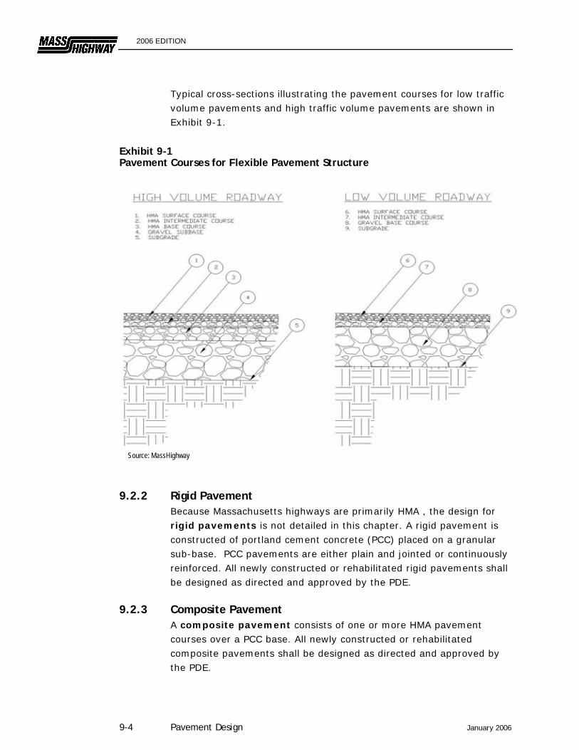
Typical cross-sections illustrating the pavement courses for low traffic volume pavements and high traffic volume pavements are shown in Exhibit 9-1.
Exhibit 9-1 Pavement Courses for Flexible Pavement Structure
Source: MassHighway
9.2.2 Rigid Pavement Because Massachusetts highways are primarily HMA , the design for rigid pavements is not detailed in this chapter. A rigid pavement is constructed of portland cement concrete (PCC) placed on a granular sub-base. PCC pavements are either plain and jointed or continuously reinforced. All newly constructed or rehabilitated rigid pavements shall be designed as directed and approved by the PDE.
9.2.3 Composite Pavement A composite pavement consists of one or more HMA pavement courses over a PCC base. All newly constructed or rehabilitated composite pavements shall be designed as directed and approved by the PDE.
9-4 Pavement Design January 2006
2006 EDITION
9.2.4 Other Pavement Concepts Research is continuing into porous and permeable pavements that have the potential to improve safety, reduce runoff and diminish undesirable environmental impacts. Some noise-reducing pavements are based on a similar premise. Permeable pavements may be constructed as full-depth porous pavements or surface friction courses. Full-depth porous pavements are constructed using specialized asphalt layers or Portland cement concrete surfaces that permit water to drain down to a specially constructed crushed stone base. This crushed stone base functions as a temporary stormwater storage area and allows the runoff to infiltrate into the sub-grade. While this design concept appears promising for low volume facilities and parking areas, the foundation needed to adopt it on larger facilities is not in place at this time. Permeable surface friction courses such as Open Graded Friction Course (OGFC) permit water to drain from the driving surface below the tire-pavement interface. This reduces hydroplaning, tire spray and tire noise while improving skid resistance and visibility. Several types of OGFC have been placed on Interstate and limited access highways in Massachusetts. Experimental pavements have been constructed which feature the use of colored aggregate in the pavement surface to improve the visual consistency of the roadway with its surroundings. Other projects have been built which feature the use of colored aggregate to improve the definition between the roadway and shoulder. These practices may be considered in special circumstances.
9.2.5 Pavement Design Terms and Definitions The following terms and abbreviations are commonly used in pavement design.
Binder – The liquid asphalt material in an HMA mixture that bonds the aggregate together.
Equivalent Single Axel Load (ESAL) – The conversion of mixed vehicular traffic into its equivalent single-axle, 18-Kip Load. The equivalence is based on the relative amount of pavement damage.
Daily ESAL (T18) – The average number of equivalent 18-Kip loads which will be applied to the pavement structure in one day.
January 2006 Pavement Design 9-5

2006 EDITION
Normally, a 20-year design period is used to determine the daily load. (See Exhibit 9-2).
ESAL Applications per 1000 Trucks and Combinations – A factor which reflects the relative mix of sizes (see Exhibit 9-2) and weights of trucks on various classes of highways (e.g., freeways, arterials, collectors, and local streets). Truck percentages typically exclude two-axle, four-tire pickup trucks, the effect of which may be ignored.
Pavement Serviceability Index (PSI) – A measure of a pavement's ability to serve traffic on a scale of 0 to 5. It reflects the extent of pavement condition.
Terminal Serviceability Index (Pt) – A pavement design factor which indicates the acceptable pavement serviceability index at the end of the selected design period (usually 20 years).
Sub-grade – The undisturbed virgin substrate or embankment material which the pavement structure is placed upon.
Bearing Ratio – The load required to produce a certain penetration using a standard piston in a soil, expressed as a percentage of the load required to force the piston the same depth in a selected crushed stone. Bearing Ration values are normally determined using the California Bearing Ratio (CBR) text method.
Design Bearing Ratio (DBR) – The selected bearing ratio used to design the pavement. It is based on a statistical evaluation of the CBR test results on the soil samples.
Soil Support Value (SSV) – An index of the relative ability of a soil or stone to support the applied traffic loads. It is specifically used for the pavement design method in the AASHTO Interim Guide for Design of Pavement Structures. The soil support value of the sub-grade is related to its CBR (DBR).
Structural Number (SN) – A measure of the structural strength of the pavement section based on the type and thickness of each layer within the pavement structure.
Layer Coefficient – The relative structural value of each pavement layer per inch of thickness. It is multiplied by the layer thickness to provide the contributing SN for each pavement layer.
Skid Resistance – A measure of the coefficient of friction between an automobile tire and the roadway surface.
9-6 Pavement Design January 2006
2006 EDITION
Pavement Design Engineer (PDE) – MassHighway Pavement Design Engineer.
Designer – The consultant under contract to MassHighway or the municipality, or the Designer within MassHighway.
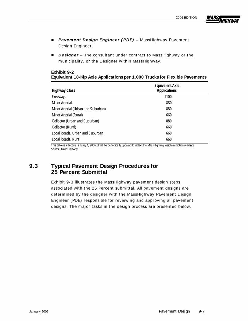
Exhibit 9-2 Equivalent 18-Kip Axle Applications per 1,000 Trucks for Flexible Pavements
Highway Class Equivalent Axle
Applications Freeways 1100 Major Arterials 880 Minor Arterial (Urban and Suburban) 880 Minor Arterial (Rural) 660 Collector (Urban and Suburban) 880 Collector (Rural) 660 Local Roads, Urban and Suburban 660 Local Roads, Rural 660 This table is effective January 1, 2006. It will be periodically updated to reflect the MassHighway weigh-in-motion readings. Source: MassHighway
9.3 Typical Pavement Design Procedures for 25 Percent Submittal
Exhibit 9-3 illustrates the MassHighway pavement design steps associated with the 25 Percent submittal. All pavement designs are determined by the designer with the MassHighway Pavement Design Engineer (PDE) responsible for reviewing and approving all pavement designs. The major tasks in the design process are presented below.
January 2006 Pavement Design 9-7
2006 EDITION
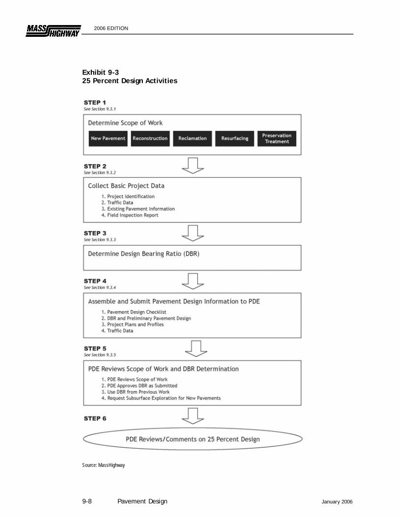
Exhibit 9-3 25 Percent Design Activities
Source: MassHighway
9-8 Pavement Design January 2006
2006 EDITION
9.3.1 Step 1 – Determine Scope of Work The Designer will determine the appropriate scope of work for the pavement design. This can be a new pavement, reconstruction, reclamation, resurfacing, pavement preservation, pedestrian/bicycle facility, or a combination of work. The scope of work may or may not include widening or corrective work to the existing pavement. To determine the scope of work for existing pavements (i.e. all work other than new pavement) the Designer shall review current Pavement Management data. Pavement Management reports will normally identify the apparent scope of pavement treatment required.
9.3.1.1 New Pavement
New pavement is a pavement structure placed on a prepared sub-grade. It applies to new highway construction, to a relocated highway, or to the new part of a widened highway.
9.3.1.2 Pavement Reconstruction
Reconstructed pavement or full depth reconstruction results when an existing pavement structure is completely removed to the sub-grade and replaced with a new pavement structure. This type of work is needed when the existing pavement has deteriorated to such a weakened condition that it cannot be salvaged with corrective action. The type and extent of pavement distress will determine when pavement reconstruction is necessary.
9.3.1.3 Pavement Reclamation
Reclaimed pavement reuses an existing pavement structure through the pulverizing and mixing of the existing pavement and granular sub-base into a gravel base material to be overlaid with new HMA layers. The reclamation method is usually performed on site.
9.3.1.4 Pavement Resurfacing
Pavement resurfacing consists of placing the needed thickness of hot mix asphalt on an existing pavement. The resurfacing will return the pavement to a high level of serviceability and provide the necessary structural strength for the pavement design period.
9.3.1.5 Pavement Preservation
Pavement Preservation involves the application of properly timed surface treatments to ensure that pavements in good condition will remain in good condition. Preservation treatments extend the pavement service life, but generally provide no structural strength.
January 2006 Pavement Design 9-9
2006 EDITION
9.3.1.6 Pedestrian and Bicycle Facilities
Pavements for pedestrian and bicycle facilities shall be designed as presented in Chapter 11 and other applicable chapters of this Guidebook. All project designs must incorporate American with Disability Act (ADA) requirements
9.3.2 Step 2 - Collect Basic Project Data The designer must collect the basic project data listed in the Pavement Design Checklist included in Appendix 9-A-1 to this chapter along with a Field Inspection Report, as described below.
9.3.2.1 Project Identification
Provide the project location information and project design engineer.
9.3.2.2 Traffic Data
At a minimum, the following traffic data is required:
Current ADT, (ADT for year of proposed opening to traffic); Projected ADT (20 years); ADT truck percentage; Number of lanes; Divided/undivided; and Source of traffic data.
9.3.2.3 Existing Pavement Information
The thickness and type of each pavement layer (i.e., surface course, intermediate course, base course, sub-base ) and sub-grade information shall be recorded. This data is necessary for proper design and analysis of the pavement structure for all types of projects. Base plans and profiles should also be obtained for purpose of pavement design.
9.3.2.4 Field Inspection Report
A field inspection report must also be prepared which includes the general condition of the roadway. The field report should note pavement deficiencies including type of distress, extent of distress and severity of distress (See Appendix 9-A-1). The report should also include other field observations such as; adequacy of drainage, presence of curbing, edging, berm or shoulder condition, sidewalks, curb cuts and driveways, and any other characteristic that may be pertinent to the analysis of the existing pavement and scope of work. The Designer should also research and document known problems with
9-10 Pavement Design January 2006

2006 EDITION
the existing pavement through discussion with field maintenance personnel.
9.3.3 Step 3 - Determine Design Bearing Ratio (DBR) Exhibit 9-4 summarizes the recommended action to determine the Design Bearing Ratio based on the Daily ESAL (T18). Projects having T18 values less than 15 should use the minimum design for the roadway’s classification (refer to Exhibit 9-11). Projects having T18 values between 15 and 120 should use DBR values based on AASHTO soils classification as shown in Exhibit 9-5. Projects having T18 values greater than 120 will require AASHTO soils classifications and CBR testing. Soil classification data and CBR test data should be submitted to the PDE for DBR determination.
Exhibit 9-4 Design Bearing Ratio Determination
Value from Line (h) of Data Sheet 1 (T18) Action
T18 < 15 Use Minimum Design (See Exhibit 9-11)
15 < T18 < 120 Assume DBR based on soil classification as determined by District lab (From Exhibit 9-5)
T18 > 120 Submit AASHTO soils classification and CBR test results to PDE for DBR determination and approval
Source: MassHighway
January 2006 Pavement Design 9-11
2006 EDITION
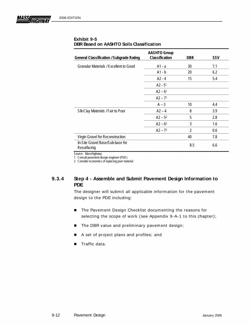
Exhibit 9-5 DBR Based on AASHTO Soils Classification
General Classification / Subgrade Rating AASHTO Group Classification DBR SSV
Granular Materials / Excellent to Good A1 - a 30 7.1 A1 - b 20 6.2 A2 - 4 15 5.4 A2 - 51 A2 – 61 A2 – 71 A – 3 10 4.4 Silt-Clay Materials / Fair to Poor A2 – 4 8 3.9 A2 – 52 5 2.8 A2 – 62 3 1.6 A2 – 72 2 0.6 Virgin Gravel for Reconstruction 40 7.8 In-Site Gravel Base/Sub-base for Resurfacing 8.5 6.6
Source: MassHighway 1 Consult pavement design engineer (PDE) 2 Consider economics of replacing poor material
9.3.4 Step 4 - Assemble and Submit Pavement Design Information to PDE The designer will submit all applicable information for the pavement design to the PDE including:
The Pavement Design Checklist documenting the reasons for selecting the scope of work (see Appendix 9-A-1 to this chapter);
The DBR value and preliminary pavement design;
A set of project plans and profiles; and
Traffic data.
9-12 Pavement Design January 2006
2006 EDITION
9.3.5 Step 5- PDE Reviews Scope of Work and DBR Determination
9.3.5.1 PDE Reviews Scope of Work
The PDE will review the Designer's recommendation, scope of pavement work, the preliminary pavement design, traffic data and the pavement checklist documenting the engineered design solution. The PDE will provide comments on the scope of work and the preliminary pavement design.
9.3.5.2 PDE Approves DBR as Submitted
The Pavement Design Engineer must approve the Design Bearing Ratio used for the design. The PDE will approve, reject, modify or request additional sampling and testing.
9.3.5.3 Use DBR from Previous Work
If it is available and still applicable, the PDE will use the DBR used for the original pavement design or any previous pavement resurfacings.
9.3.5.4 Request Subsurface Exploration for New Pavements
If the Designer recommends a subsurface exploration to determine the soil gradation, properties and stratification data and the PDE has concurred, the Designer will submit a written request to MassHighway, Pavement Management Section and include the following information. The Designer will prepare the requested soil exploration method and plan. The method and plan will include test pit, pavement cores, etc. the required number and their locations. This information is to be in written form and shown on project base plans and forwarded to MassHighway, Chief Engineer, to the attention: Pavement Design Engineer.
9.3.6 STEP 6 - PDE Reviews/Comments on the 25 Percent Design The PDE will review and comment on the 25 Percent Design recommendation from the Design engineer.
January 2006 Pavement Design 9-13
2006 EDITION
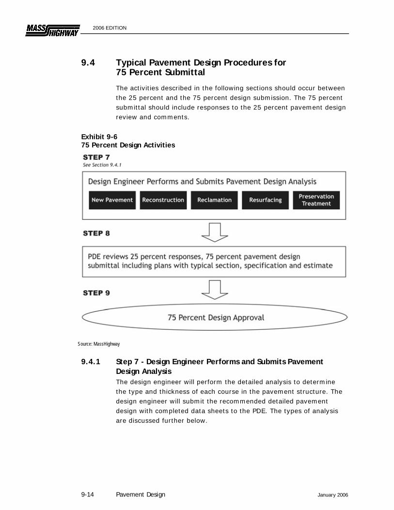
9.4 Typical Pavement Design Procedures for 75 Percent Submittal
The activities described in the following sections should occur between the 25 percent and the 75 percent design submission. The 75 percent submittal should include responses to the 25 percent pavement design review and comments.
Exhibit 9-6 75 Percent Design Activities
Source: MassHighway
9.4.1 Step 7 - Design Engineer Performs and Submits Pavement Design Analysis The design engineer will perform the detailed analysis to determine the type and thickness of each course in the pavement structure. The design engineer will submit the recommended detailed pavement design with completed data sheets to the PDE. The types of analysis are discussed further below.
9-14 Pavement Design January 2006
2006 EDITION
9.4.1.1 New Pavements
On new pavements, the designer will determine the detailed full-depth design of the pavement. The detailed procedure is discussed in Section 9.5.
9.4.1.2 Pavement Reconstruction
On reconstructed pavement, the designer will determine the detailed full-depth design of the pavement. The detailed procedure is discussed in Section 9.5.
9.4.1.3 Pavement Reclamation
For reclaimed pavements, the Designer will determine the depth of reclamation required. A minimum 12” granular base or sub-base course must be provided beneath the HMA pavement courses. The detailed procedure is as outlined in Section 400 of the Standard Specifications for Highways and Bridges.
9.4.1.4 Pavement Resurfacing
On pavement resurfacing, the Designer will specify the depth of milling, if required, leveling course, if used, and the depth and mixture type for the HMA resurfacing course(s). The detailed procedure is discussed in Section 9.6. In addition, the Designer will determine any corrective work needed on the existing pavement.
9.4.1.5 Pavement Preservation
The design/selection of all pavement preservation treatments must be in accordance with the MassHighway Pavement Preservation Guidelines. The Designer shall submit the proposed treatment type and surface preparation requirements to the PDE for approval.
9.4.2 Step 9 - PDE Reviews Pavement Design Analysis The PDE will review, comment and approve or request modifications to the pavement design recommendation from the Design engineer.
9.5 New and Reconstructed Pavements
This section specifies the MassHighway procedure for determining the detailed design of a new or reconstructed pavement. This procedure applies to HMA pavements only. MassHighway uses the AASHTO Interim Guide for Design of Pavement Structures as the basic design methodology. However, MassHighway has incorporated several
January 2006 Pavement Design 9-15

2006 EDITION
modifications to the Guidebook's procedures to reflect specific conditions in Massachusetts and to simplify the procedure. The Pavement Design Form – New or Reconstructed Pavements (cover sheet and data sheets 1 through 3) are included in Appendix 9-A-2 to this chapter. This form must be completed by the Designer and submitted to the PDE prior to the 75 Percent Submittal.
9.5.1 Pavement Design Cover Sheet The following information must be recorded on the cover sheet:
Enter the project identification data at the top of the cover sheet.
Summarize the recommended pavement design by documenting the surface, base, and sub-base data. List the depths, type of layer, and recommended lifts.
Describe the special borrow, if required for the project. Special borrow may be necessary where the existing sub-grade is susceptible to frost penetration within the typical frost penetration depth. If this subsurface condition exists, subsurface exploration and soil analysis may be warranted. The Designer will recommend the type and depth of special borrow to be used for frost control. Special Borrow is generally placed on freeways and arterial routes. Consideration for placement on other roads will depend on functional classification, traffic volumes, presence of utilities, construction methods, etc.
9.5.2 Data Sheet 1: Pavement Structural Design Data Data Sheet 1 includes the following information:
Line (a): Enter the anticipated (current) ADT for date of opening.
Line (b): Enter the future ADT (see Chapter 3 for information on traffic volume forecasts). Generally the design period for pavements is 20 years; however there may be occasions when the traffic information submitted does not cover the design period. In these cases the future ADT is to be estimated by approved methods. Under certain circumstances, pavements may be designed for periods of less than 20 years.
Line (c): Calculate the average ADT during the design period.
Line (d): Calculate the average ADT in one direction.
9-16 Pavement Design January 2006
2006 EDITION
Line (e): Enter the truck percentage for the ADT.
Line (f): Calculate the average daily truck volume in one direction.
Line (g): Enter the equivalent 18-Kip axle application per 1,000 trucks and combinations. (See Exhibit 9-2).
Line (h): Calculate the number of 18-Kip axle loads per day in one direction (T18).
9.5.2.1 Design Bearing Ratio (DBR) Determination
Use the value on Line (h) (T18) and Exhibit 9-4 to determine the sub-grade or Sub-base DBR. As noted the PDE may be required to provide the DBR. In all cases, Designers make a general computation of the sub-grade or sub-base DBR for reviews by the Pavement Design Engineer. See Section 9.3 above.
9.5.3 Data Sheet 2: Determining Structural Number (SN) The following steps are required to determine the structural number (SN):
Step 1: Determine the design lane equivalent daily 18-Kip applications based on the number of lanes.
Step 2: Determine the DBR for the sub-grade from Exhibit 9-4 and 9-5. The sub-base DBR is 40 for the typical MassHighway sub-base on new or reconstructed pavements (gravel).
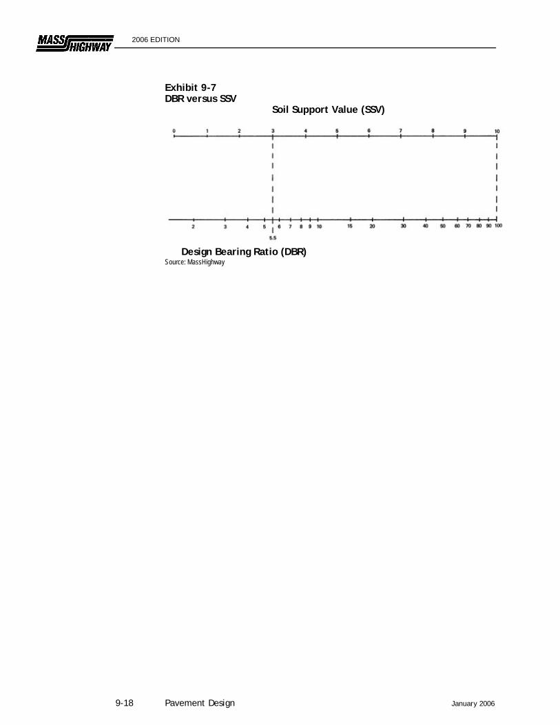
Step 3: Determine the soil support value (SSV). Exhibit 9-7 illustrates the relationship between the DBR and SSV.
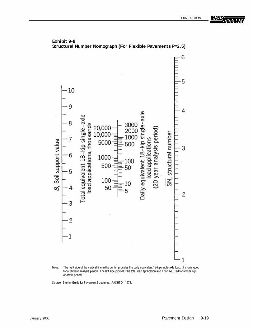
Step 4: Determine the required structural number (SN) above the sub-base and above the sub-grade. Exhibit 9-8 should be used. Use the design-lane T18 from Step 1 for the daily equivalent 18-Kip single axle load. Use the SSV from Step 3 for the soil support value.
Step 5: Increase the SN by 15 percent to determine the design SN to adjust for climatic and other environmental conditions.
January 2006 Pavement Design 9-17
2006 EDITION
Exhibit 9-7 DBR versus SSV Soil Support Value (SSV)
Design Bearing Ratio (DBR) Source: MassHighway
9-18 Pavement Design January 2006
2006 EDITION
Exhibit 9-8 Structural Number Nomograph (For Flexible Pavements P=2.5)
Note: The right side of the vertical line in the center provides the daily equivalent 18-kip single-axle load. It is only good
for a 20-year analysis period. The left side provides the total load application and it can be used for any design analysis period.
Source: Interim Guide for Pavement Structures. AASHTO. 1972.
January 2006 Pavement Design 9-19
2006 EDITION
9.5.4 Data Sheet 3: Pavements Structural Number (SN) By trial and error, the designer will select the most cost-effective design that provides the required SN for the highway conditions. The designer should also consider minimum and maximum lift thicknesses and the logistics of construction procedures when designing the pavement design combinations using this procedure.
Step 1: Select each pavement layer component and the thickness of each layer.
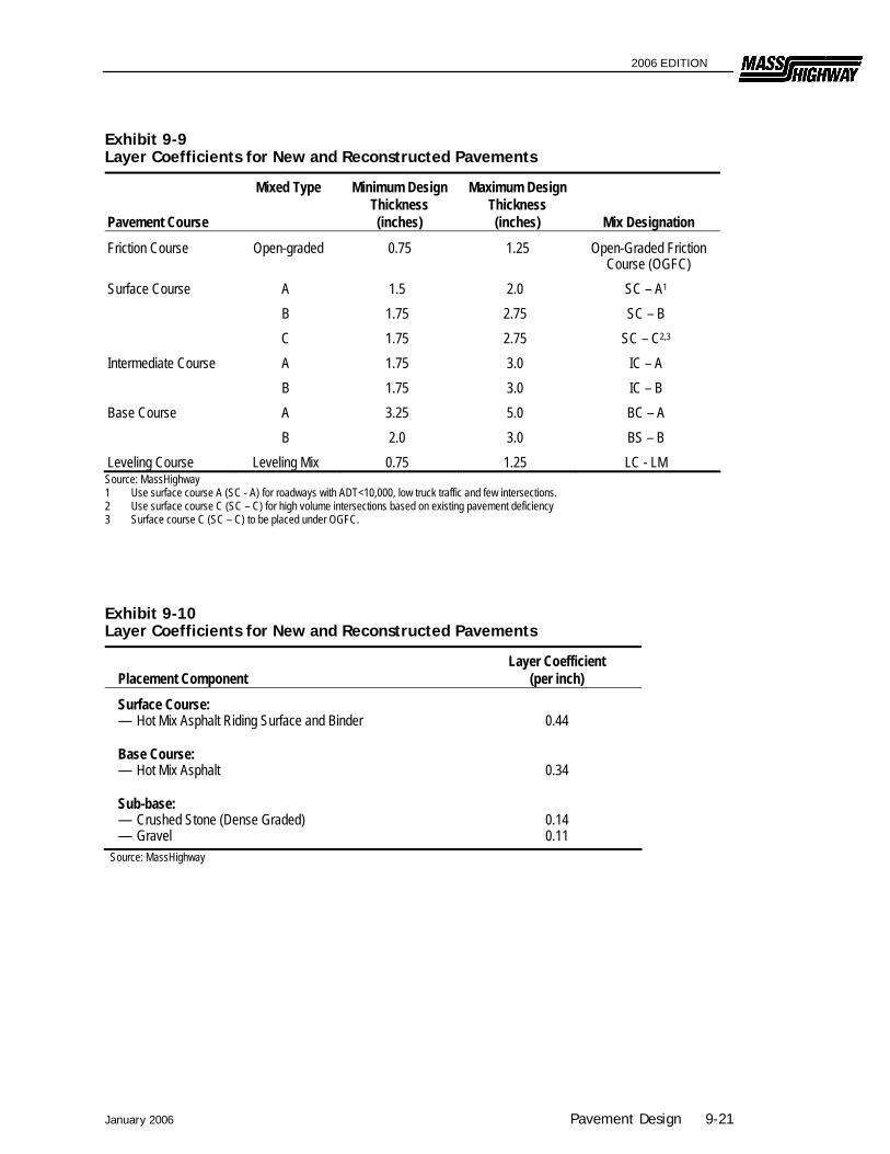
Step 2: From Exhibit 9-10 select the layer coefficient for each pavement layer.
Step 3: Determine the contributing SN for each pavement layer by multiplying the layer coefficient by its thickness.
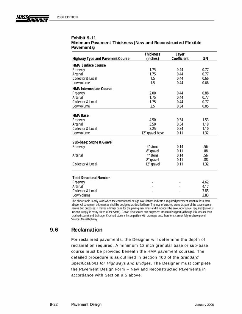
Step 4: The minimum thicknesses of each layer are noted on Exhibit 9-11.
Step 5: Check to ensure that the required SN is provided above the sub-base and the sub-grade. If not, increase the layer thickness as necessary. If the trial design exceeds the required SN, reduce the layer thicknesses.
Step 6: Determine several alternate pavement designs which satisfy the SN requirements. The selected design will be based on economics.
Step 7: Regardless of the calculations from the pavement design analysis, the minimum design thickness should not be less than those shown in Exhibit 9-11.
9-20 Pavement Design January 2006
2006 EDITION
Exhibit 9-9 Layer Coefficients for New and Reconstructed Pavements
Pavement Course
Mixed Type Minimum Design Thickness (inches)
Maximum Design Thickness (inches) Mix Designation
Friction Course Open-graded 0.75 1.25 Open-Graded Friction Course (OGFC)
Surface Course A 1.5 2.0 SC – A1
B 1.75 2.75 SC – B C 1.75 2.75 SC – C2,3
Intermediate Course A 1.75 3.0 IC – A B 1.75 3.0 IC – B Base Course A 3.25 5.0 BC – A B 2.0 3.0 BS – B Leveling Course Leveling Mix 0.75 1.25 LC - LM Source: MassHighway 1 Use surface course A (SC - A) for roadways with ADT<10,000, low truck traffic and few intersections. 2 Use surface course C (SC – C) for high volume intersections based on existing pavement deficiency 3 Surface course C (SC – C) to be placed under OGFC.
Exhibit 9-10 Layer Coefficients for New and Reconstructed Pavements
Placement Component Layer Coefficient
(per inch) Surface Course: — Hot Mix Asphalt Riding Surface and Binder
0.44
Base Course: — Hot Mix Asphalt
0.34
Sub-base: — Crushed Stone (Dense Graded) — Gravel
0.14 0.11
Source: MassHighway
January 2006 Pavement Design 9-21
2006 EDITION
Exhibit 9-11 Minimum Pavement Thickness (New and Reconstructed Flexible Pavements) Highway Type and Pavement Course
Thickness (inches)
Layer Coefficient
SN
HMA Surface Course Freeway 1.75 0.44 0.77 Arterial 1.75 0.44 0.77 Collector & Local Low volume
1.5 1.5
0.44 0.44
0.66 0.66
HMA Intermediate Course Freeway 2.00 0.44 0.88 Arterial 1.75 0.44 0.77 Collector & Local Low volume
1.75 2.5
0.44 0.34
0.77 0.85
HMA Base Freeway 4.50 0.34 1.53 Arterial 3.50 0.34 1.19 Collector & Local Low volume
3.25 12” gravel base
0.34 0.11
1.10 1.32
Sub-base: Stone & Gravel Freeway 4” stone
8” gravel 0.14 0.11
.56
.88 Arterial 4” stone
8” gravel 0.14 0.11
.56
.88 Collector & Local
12” gravel
0.11
1.32
Total Structural Number Freeway - - 4.62 Arterial - - 4.17 Collector & Local Low Volume
- - 3.85 2.83
The above table is only valid when the conventional design calculations indicate a required pavement structure less than above. All pavement thicknesses shall be designed as detailed here. The use of crushed stone as part of the base course serves two purposes: it makes a firmer base for the paving machines and it reduces the amount of gravel required (gravel is in short supply in many areas of the State). Gravel also serves two purposes: structural support (although it is weaker than crushed stone) and drainage. Crushed stone is incompatible with drainage and, therefore, cannot fully replace gravel. Source: MassHighway
9.6 Reclamation
For reclaimed pavements, the Designer will determine the depth of reclamation required. A minimum 12 inch granular base or sub-base course must be provided beneath the HMA pavement courses. The detailed procedure is as outlined in Section 400 of the Standard Specifications for Highways and Bridges. The Designer must complete the Pavement Design Form – New and Reconstructed Pavements in accordance with Section 9.5 above.
9-22 Pavement Design January 2006
2006 EDITION
9.7 Pavement Resurfacing
A pavement resurfacing can be used if the Designer determines that an existing pavement is in reasonably good condition. A pavement resurfacing may be in conjunction with roadway widening and/or corrective work to the existing pavement. The Pavement Resurfacing Design Form and a completed example (cover sheet and data sheets 1 to 3) is included in Appendix 9-A-3 to this chapter. The depth of HMA resurfacing will be determined by the following procedure.
9.7.1 Pavement Resurfacing Design Cover Sheet The following must be recorded on the Pavement Resurfacing Design Coversheet:
Enter the project identification data at the top of the cover sheet. Document the existing pavement structure before resurfacing. Record the recommended pavement resurfacing thickness.
9.7.2 Data Sheet 1: Pavement Structural Design Data Data Sheet 1 should be completed using the following procedure:
Line (a): Enter the current ADT.
Line (b): Enter the future ADT, (see Chapter 3 for information on traffic forecasts) usually for 20 years beyond the current. Note that the traffic data available may not correspond to the dates in Lines (a) and (b). If not, the designer should assume a uniform straight-line increase between the data. This assumption can then be used to determine the traffic volumes in Lines (a) and (b).
Line (c): Calculate the average ADT during the design period.
Line (d): Calculate the average ADT in one direction.
Line (e): Enter the truck percentage for the ADT.
Line (f): Calculate the average daily truck volume in one direction.
Line (g): Enter the equivalent 18-Kip axle application per 1,000 trucks and combinations (See Exhibit 9-2).
Line (h): Calculate the number of 18-Kip axle loads per day in one direction (T18).
January 2006 Pavement Design 9-23
2006 EDITION
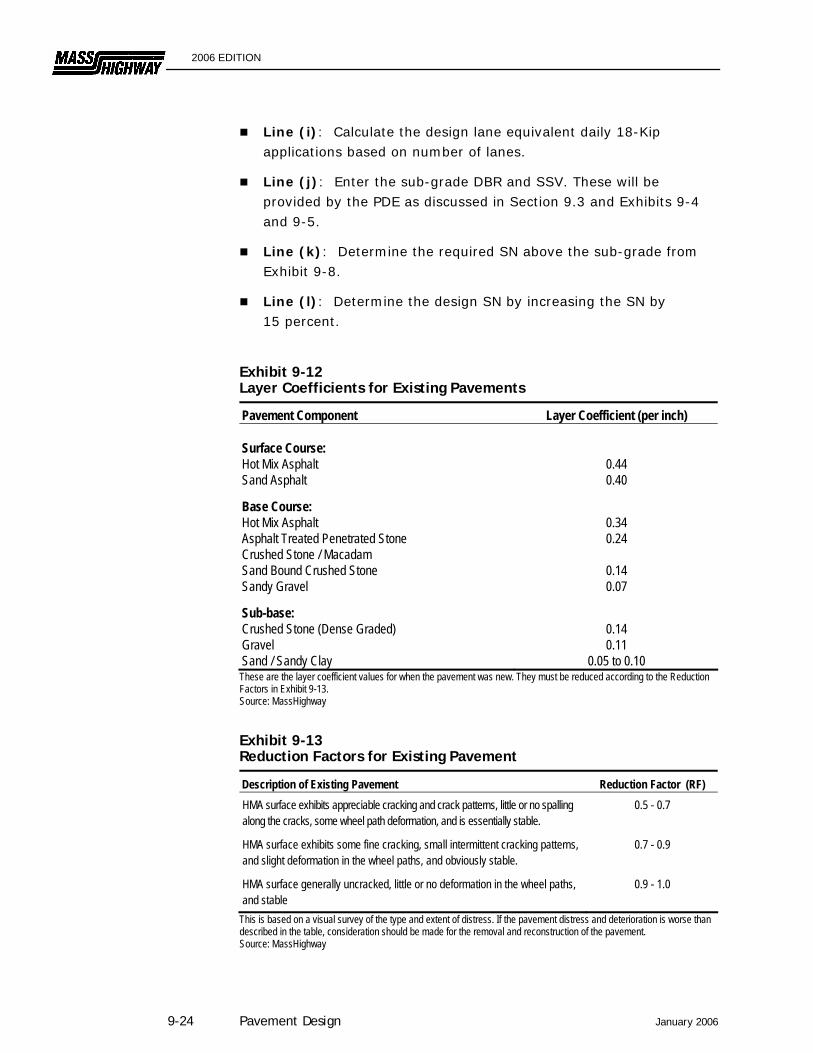
Line (i): Calculate the design lane equivalent daily 18-Kip applications based on number of lanes.
Line (j): Enter the sub-grade DBR and SSV. These will be provided by the PDE as discussed in Section 9.3 and Exhibits 9-4 and 9-5.
Line (k): Determine the required SN above the sub-grade from Exhibit 9-8.
Line (l): Determine the design SN by increasing the SN by 15 percent.
Exhibit 9-12 Layer Coefficients for Existing Pavements
Pavement Component Layer Coefficient (per inch) Surface Course: Hot Mix Asphalt Sand Asphalt
0.44 0.40
Base Course: Hot Mix Asphalt Asphalt Treated Penetrated Stone Crushed Stone / Macadam Sand Bound Crushed Stone Sandy Gravel
0.34 0.24
0.14 0.07
Sub-base: Crushed Stone (Dense Graded) Gravel Sand / Sandy Clay
0.14 0.11
0.05 to 0.10 These are the layer coefficient values for when the pavement was new. They must be reduced according to the Reduction Factors in Exhibit 9-13. Source: MassHighway
Exhibit 9-13 Reduction Factors for Existing Pavement
Description of Existing Pavement Reduction Factor (RF) HMA surface exhibits appreciable cracking and crack patterns, little or no spalling along the cracks, some wheel path deformation, and is essentially stable.
0.5 - 0.7
HMA surface exhibits some fine cracking, small intermittent cracking patterns, and slight deformation in the wheel paths, and obviously stable.
0.7 - 0.9
HMA surface generally uncracked, little or no deformation in the wheel paths, and stable
0.9 - 1.0
This is based on a visual survey of the type and extent of distress. If the pavement distress and deterioration is worse than described in the table, consideration should be made for the removal and reconstruction of the pavement. Source: MassHighway
9-24 Pavement Design January 2006
2006 EDITION
9.7.3 Data Sheet 2: Actual SN of Existing Pavement The following steps are required to complete Data Sheet 2:
Line (a): Enter the SSV of the existing pavement elements. The SSV for the penetrated crushed stone base, the sand bound crushed stone base, and the gravel sub-base are usually assumed as shown. However, if laboratory-determined DBR results are available, these values should be used. Enter the SSV for the sub-grade from Line (j) of Data Sheet 1.
Line (b): Determine the SN of the existing pavement. Follow these steps:
Exhibit 9-10 provides the layer coefficient for each layer component for a new pavement.
The coefficients in Exhibit 9-12 should be multiplied by a reduction factor (RF) from Exhibit 9-13. The RF will be based on a visual survey of the type and extent of distress in the existing pavement. The RF will apply even if corrective work is performed on the existing pavement.
The contributing SN for each layer is calculated by multiplying its depth by the layer coefficient and RF.
The total SN is found by summing the SN of each pavement layer.
(Note: If Portland Cement Concrete is part of the existing pavement, the PDE will determine its contributing SN.)
Line (c): Determine the actual SN above each layer of the existing pavement. The SN for each layer is entered in the appropriate column. The "Total SN" reflects the cumulative SN above each pavement layer.
9.7.4 Data Sheet 3: Determination of Resurfacing Thickness The following steps are needed to complete Data Sheet 3:
Line (a): Determine the required SN above each layer of the existing pavement using Exhibit 9-8. The values from Line (i) on Data Sheet 1 and from Line (a) of Data Sheet 2 are used in the figure. The SN values from Exhibit 9-8 are increased by 15 percent to determine the design SN.
Line (b): Determine the SN deficiency for each layer for the existing pavement. The required SN from Line (a) of Data Sheet 3 is entered in
January 2006 Pavement Design 9-25
2006 EDITION
the first column. Enter the value from Line (c) of Data Sheet 2 in the second column. The first column SN minus the second column SN yields the SN difference, which is entered in the third column. (Note: A negative value indicates there is no SN deficiency for that pavement layer.)
Line (c): The largest SN deficiency from the table in Line (b) is used to determine the thickness of the pavement resurfacing. The SN per inch is 0.44 for the Hot Mix Asphalt surface course. Regardless of the calculation, the minimum overlay thickness is 1 ¾ inch for modified top course.
9.8 Limited Access Highway Pavement Resurfacing Design
Due to the high traffic volumes and loadings on limited access highways, MassHighway maintains the ability to perform non-destructive testing and evaluate the pavement and subsurface conditions for these roadways. When designing structural resurfacings on limited access highways, the PDE may elect to use non-destructive testing to determine the appropriate resurfacing. The following general parameters are considered the minimum standards for these roadways:
9.8.1 Design Method Both a layered component analysis and non-destructive testing analysis should be reviewed to calculate the effective existing SN.
9.8.2 Serviceability An initial serviceability no greater than 4.5 should be assumed. A terminal serviceability no greater than 2.75 should be selected.
9.8.3 Reliability Traffic disruption and congestion associated with construction operations result in significant user costs. Increased design reliability helps reduce these user costs. Thus, reliability levels approaching 99.9 percent are used to design structural resurfacings on the Interstate Highway System. Reliability levels approaching 99.5 percent should be used to design structural resurfacings on other limited access highway.
9.8.4 Back-calculation Non-destructive testing must be analyzed to determine the resilient modulus of the soil. Because differing stress states occur between field conditions and lab conditions, a correction factor must be used to
9-26 Pavement Design January 2006
2006 EDITION
convert field-determined modulus values to lab values for design calculations. For granular soils, a resilient modulus correction factor (C) of 0.33 shall be used. Depending upon the project, the back-calculated resilient modulus values of the sub-grade could vary significantly. Extremely high modulus values could be indicative of subsurface irregularities such as shallow bedrock or groundwater. To minimize the possibility of such erroneous modulus values, only modulus values within one standard deviation of the mean should be used to calculate the average resilient modulus for design purposes.
9.8.5 1993 AASHTO Pavement Resurfacing Design Once the non-destructive testing has been analyzed and the future traffic loadings have been determined, the PDE will determine the required future structural number.
9.9 Pavement Preservation
The design/selection of all pavement preservation treatments must be in accordance with the MassHighway Pavement Preservation Guidelines. The Designer shall submit the proposed treatment type and surface preparation requirements to the PDE for approval.
9.10 Typical Pavement Design for Low Volume Roads
In this revision of the Guidebook, the minimum pavement cross section has been reduced for low volume roads (2,000 AADT maximum). This new minimum cross section has eliminated the use of HMA base course and provides for the placement of Gravel Base Course in its place. These revisions are reflected in Exhibit 9-10 Minimum Pavement Thickness (New and Reconstructed Flexible Pavements).
9.10.1 Design Procedures For the purpose of designing pavements on low volume roadways, the Designer should begin with the minimum low volume roadway cross section as shown on Exhibit 9-11. This design should be adequate for virtually all roadways less than 1,000 AADT and most roadways less than 2,000 AADT and 3percent truck traffic. If the design calculations indicate that a greater thickness is required, then the Designer should adjust the pavement layer thickness accordingly.
January 2006 Pavement Design 9-27

2006 EDITION
9.11 For Further Information
Interim Guide for Design of Pavement Structures, AASHTO, 1972 (Revised 1993).
Layered Pavement Design Method for Massachusetts, Massachusetts Department of Public Works and Massachusetts Institute of Technology, January, 1965.
9-28 Pavement Design January 2006