Embed Size (px)
Citation preview

Pavement Assessment, Repair and Renewal Principles (including Erratum No. 1 dated June 2015 and Erratum No 2, dated January 2016)
AM-PAV-06050 March 2015
Asset Management & Maintenance StandardsAM

TRANSPORTINFRASTRUCTUREIRELAND(TII)PUBLICATIONS
AboutTII
TransportInfrastructureIreland(TII)isresponsibleformanagingandimprovingthecountry’snationalroadandlightrailnetworks.
AboutTIIPublications
TII maintains an online suite of technical publications, which is managed through the TIIPublications website. The contents of TII Publications is clearly split into ‘Standards’ and‘Technical’documentation.AlldocumentationforimplementationonTIIschemesiscollectivelyreferredtoasTIIPublications(Standards),andallotherdocumentationwithinthesystemiscollectively referred to asTII Publications (Technical).This system replaces theNRADesignManual forRoadsandBridges (NRADMRB)and theNRAManualofContractDocuments forRoadWorks(NRAMCDRW).
DocumentAttributes
EachdocumentwithinTIIPublicationshasarangeofattributesassociatedwithit,whichallowsforefficientaccessandretrievalof thedocument fromthewebsite.Theseattributesarealsocontained on the inside cover of each current document, for reference. For migration ofdocumentsfromtheNRAandRPAtothenewsystem,eachcurrentdocumentwasassignedwithnewouterfrontandrearcovers.Apartfromthecovers,andinsidecoverpages,thedocumentscontainthesameinformationaspreviouslywithintheNRAorRPAsystems,includinghistoricalreferencessuchasthosecontainedwithinNRADMRBandNRAMCDRW.
DocumentAttributes
TIIPublicationTitle Pavement Assessment, Repair and Renewal Principles (includingErratumNo. 1 dated June 2015 andErratumNo 2, dated January2016)
TIIPublicationNumber AM‐PAV‐06050
Activity AssetManagement&Maintenance(AM) DocumentSet Standards
Stream Pavement(PAV) PublicationDate March2015DocumentNumber
06050 HistoricalReference
NRAHD31
NRADMRBandMCDRWReferences
ForalldocumentsthatexistedwithintheNRADMRBortheNRAMCDRWpriortothelaunchofTIIPublications,theNRAdocumentreferenceusedpreviouslyislistedaboveunder‘historicalreference’. The TII Publication Number also shown above now supersedes this historicalreference.AllhistoricalreferenceswithinthisdocumentaredeemedtobereplacedbytheTIIPublication Number. For the equivalent TII Publication Number for all other historicalreferencescontainedwithinthisdocument,pleaserefertotheTIIPublicationswebsite.

Volume 7: Pavement Design & Maintenance
Pavement Assessment, Repair and Renewal
Principles (including Erratum No. 1, dated June 2015
and Erratum No 2, dated January 2016)
Volume 7 Section 3 Part 4
NRA HD 31/15
March 2015
St. Martin’s House, Waterloo Road, Dublin 4 Tel: +353 1 660 2511 Fax +353 1 668 0009 Email: [email protected] Web: www.nra.ie

Summary: This Design Standard relates to the assessment of existing pavements and the development of asset repair and renewal proposals. It contains material from UK DMRB HD 29, HD 30 and HD 31 relevant to Irish conditions. Published by National Roads Authority, Dublin 2015

NRA DESIGN MANUAL FOR ROADS AND BRIDGES
March 2015 i
VOLUME 7 Pavement Design and Maintenance
SECTION 3 Pavement Maintenance Assessment and Renewal
PART 4 NRA HD 31/15 Pavement Assessment, Repair and Renewal Principles (including Erratum No. 1, dated June 2015 & Erratum No. 2, dated January 2016) Contents
Chapter
1 Introduction
2 Review of Data from the NRA Pavement Asset Management
System
3 Visual Inspection Report
4 Scheme Level Surveys and Investigations
5 Interpretation and Analysis of Data
6 Pavement Surface Treatment Options
7 Structural Strengthening of the Pavement
8 Pavement Drainage
9 References
10 Enquiries
Erratum No. 1
Erratum No. 2
APPENDIX A: NRA Pavement Asset Management System
APPENDIX B: Falling Weight Deflectometer Surveys and
Analysis
APPENDIX C: Coring and Trial Pits
APPENDIX D: Dynamic Cone Penetrometer
APPENDIX E: Laboratory Testing
APPENDIX F: Ground Penetrating Radar
APPENDIX G: Carriageway Pavement Defect Types

National Roads Authority Volume 7 Section 3 Design Manual for Roads and Bridges Part 4 NRA HD 31/15
(Including Errata No. 1 and 2)
March 2015 1
1. INTRODUCTION General
1.1 1The purpose of this Standard is to provide guidance on the principles to be followed for Pavement Asset Repair and Renewal (PARR) and should be read in association with NRA HD 30 - Pavement Asset Repair and Renewal - Scheme Approval Procedure.
1.2 The Standard provides detailed guidance to Implementation Authorities and Design Organisations on the technical aspects of the investigation and design of PARR Schemes with the overall objective of maintaining the overall asset value for the minimum life cycle costs by ensuring the optimal management of the National Road network. The Standard provides information on the review of data from the NRA Pavement Asset Management System (PAMS), visual inspections of pavement and drainage, scheme level surveys and investigations, interpretation of data, treatment options and drainage.
1.3 As pavements age they suffer deterioration due to the effects of traffic, weather and sunlight which manifests as polishing, rutting, fretting, ravelling and cracking which leads over time to a disintegration of the surface layer. The source of this deterioration may either be limited to the surface or be a sign of more deep-seated structural issues related to the pavement.
1.4 PARR is required when these signs of wear are judged to affect the standards of service provided to the road user and the integrity of the pavement structure. To carry out the PARR in the most cost-effective manner, it is necessary to use a logical assessment procedure to ensure that the optimal maintenance treatment is carried out at the optimum time. The potential treatments can range from the replacing of surface courses to full reconstruction of the pavement. The adopted treatments must align with the objectives of the schemes and the available budget.
1.5 NRA HD 30 sets out the NRA documentation requirements and approval gateways for pavement repair and renewal schemes on the National Road network. All PARR schemes must be processed through the Gateways. This will ensure consistency of approach and provide a record that scheme objectives have been achieved and the required information is recorded within the PAMS system.
1.6 The close out requirements for the PARR Scheme are specified in NRA HD 30 and comprise of the preparation of the Final Account Report, information for the PAMS Database, Safety File, Opportunity Register and archive information which is to be retained by the Implementation Authority. The information for the PAMS Database is particularly important as this records the Works done within the PAMS and provides cost information for future updates and treatments.
1.7 Compliance with NRA HD 30 is mandatory.
1.8 Other relevant documents include:
a) NRA Specification for Road Works, Series 900, Road Pavements – Bituminous Materials.
b) NRA HD 36 Surfacing Materials for New and Maintenance Construction, for use in Ireland.
c) NRA HD 37 Bituminous Surfacing Materials and Techniques.
1.9 This Standard does not give any advice in respect of skid resistance which is addressed in NRA HD 28 - Management of Skid Resistance. NRA HD 28 provides advice and guidance to assist the Designer in determining an appropriate level of skid resistance for each site.
1 Amended as per Erratum No. 1, item 1

National Roads Authority Volume 7 Section 3 Design Manual for Roads and Bridges Part 4 NRA HD 31/15
(Including Errata No. 1 and 2)
March 2015 2
1.10 This Standard does not address pavements with hydraulically bound foundation / lower base layer. If these are identified then specific advice should be sought from NRA Network Management on the testing and the PARR measures to be adopted.
Implementation
1.11 The procedures described in this Standard shall be followed for all PARR Schemes on National Roads. The Standard should be applied to schemes already being prepared unless, in the opinion of the National Roads Authority (NRA), application would result in significant additional expense or delay progress. In such cases the Implementation Authority should confirm the application of this Standard to particular schemes with NRA Network Management (NRA NM).
Definitions
1.12 For definitions of the general road terms used in this Standard such as components of the road (central reserve, verge, hard shoulder, and hard strip, etc.) see BS 6100: Subsection 2.4.1 or the equivalent European Standard as applicable.
1.13 The following definitions will apply to this Standard:
a) Approval Gateway: An Approval Gateway is a systematic review of proposals which require formal NRA approval prior to proceeding to the next stage of the process.
b) As-Built Record: Record of construction which can include but is not limited to drawings, documents, photographs, surveys, maps, models or any other record, providing a final statement of what works were completed on a road construction scheme. The as built records will comply with the requirements of NRA GD 101.
c) Design Organisation: Usually an Implementation Authority, National Roads Design Office (or a Consultant acting on their behalf) who is responsible for the design of the Scheme.
d) Designer: The Designer will be a Chartered Engineer or equivalent and who has at least 5 years’ experience in the design and supervision of PARR Schemes. This experience should include a thorough understanding of the interaction between the attributes of drainage, geotechnics, utility issues, land issues and pavement design.
e) Employer’s Agent: Person(s) appointed by the Employer’s Representative responsible for the routine supervision of the Contract. The Agent must have at least 3 years of experience in the design and supervision of PARR schemes.
f) Employer’s Representative: As defined in the Public Works Contract.
g) Emergency Pavement Repairs: PARR schemes which have to be carried out quickly in response to emergencies to ensure the safety and continued serviceability of the road. These repairs may follow crashes, diesel spillage or unexpected and rapid deterioration of the pavement.
h) Implementation Authority: The Implementation Authority shall be the relevant Local Authority responsible for the PARR scheme or for the purposes of this procedure the MMaRC Contractor.
i) Isolated Pavement Repairs: PARR schemes for small and isolated repairs not exceeding €50,000 in cost or 375m2 in area.
j) Life Cycle Cost Analysis: (LCCA): Life-cycle cost analysis is the process of calculating whether a particular investment, resultant from a specific design strategy, will generate a positive return on investment over the life of the renewed pavement.

National Roads Authority Volume 7 Section 3 Design Manual for Roads and Bridges Part 4 NRA HD 31/15
(Including Errata No. 1 and 2)
March 2015 3
k) Minor Improvement Scheme: An upgrade to an existing section of road less than 2km in length where a geometric design element or combined set of geometric design elements are improved. Guidance on Minor Improvement Schemes is provided in NRA TA 85.
l) Motorway Maintenance and Renewals Contract (MMaRC): Contractors appointed to maintain, operate and renew sections of the motorway network.
m) National Road Network: The primary and secondary road network in Ireland which is operated and maintained by the NRA and which comprises motorways, dual carriageways and single carriageway roads.
n) NRA: National Roads Authority.
o) NRA Network Management (NRA NM): Division within the NRA responsible for the management and operation of the road network including responsibility for pavement management and the operation of the NRA Pavement Asset Management System (PAMS).
p) NRA Network Management System (NRA NMS): Database used to store information relating to the maintenance of the National Road network.
q) NRA Regional Management (NRA RM): Division within the NRA responsible for the delivery of the roads programme for the Network within specific geographic regions.
r) Original Cross-Sectional Profile: The cross-sectional profile of the road as originally constructed and prior to any deterioration including settlement during the subsequent use of the road pavement. If drawings and other records are not available then engineering judgement may need to be applied to establish the original profile.
s) Pavement Asset Management System (PAMS): The network pavement asset management system which is maintained and managed by the NRA NM.
t) Pavement Asset Repair and Renewal (PARR): Activity targeted at extending the life of an existing road pavement and/or improve its load carrying capacity or skid resistance. Examples include overlay and inlay works and edge strengthening of an existing road pavement.
u) Resource Management Plan: Plan to be submitted by the Implementation Authority when direct labour resources are utilised to carry out the PARR Schemes.
v) Routine Maintenance: Programmed and reactive maintenance activities required to maintain the serviceability and durability of the road. Examples include:
a. Drain and drainage inlet maintenance.
b. Footpath and verge maintenance.
c. Grass cutting.
d. Signage maintenance.
e. Landscape and hedge maintenance.
f. Safety barrier and fence maintenance.
g. 2Isolated patching and pothole repairs on structurally sound pavements which does not exceed 75m2 in area or €10,000 in cost.
h. Litter picking.
i. Gutter cleaning and road sweeping.
j. Emergency works.
2 Amended as per Erratum No. 1, item 2

National Roads Authority Volume 7 Section 3 Design Manual for Roads and Bridges Part 4 NRA HD 31/15
(Including Errata No. 1 and 2)
March 2015 4
Mutual Recognition
1.14 The construction and maintenance of road pavements will normally be carried out under contracts incorporating the NRA Specification for Road Works. In such cases works, goods or materials conforming to harmonised European Standards (hEN) where applicable will be acceptable in accordance with the terms of Clauses 104 and 105 of the NRA Specification for Road Works. Contracts that do not contain these clauses must contain suitable clauses of mutual recognition having the same effect. Advice should be sought in relation to such situations from the NRA Head of Network Management Engineering Standards and Research.
1.15 Construction products must be supplied with appropriate CE marking in accordance with the Construction Products Regulation (CPR) or as required by the NRA Specification for Road Works.
1.16 In order to allow a manufacturer of a construction product to draw up a declaration of performance for a construction product which is not covered or not fully covered by a harmonised standard, it is necessary to provide for a European Technical Assessment for these products. For more information on the implementation of the Construction Products Regulation in Ireland visit the Building Standards Section of the Department of Environment:
http://www.environ.ie/en/Publications/DevelopmentandHousing/BuildingStandards
Departures from Design Standards
1.17 In exceptional situations, the NRA may be prepared to agree to a Departure from Standards. Design Organisations wishing to consider pursuing this course shall discuss any such option at an early stage in design with the NRA NM. Proposals to adopt Departures from Standard must be submitted by the Design Organisation to the NRA and formal approval received BEFORE incorporation into a design layout.
PARR Scheme Objectives
1.18 The overall strategic objective of the PARR Standards is to provide a Framework to maintain the total asset value for the minimum life cycle costs by ensuring optimal management of the National Road network.
1.19 Roads have a myriad of construction types, mix of traffic usage and constraints which are specific to each site. It is therefore important that the Specific Objectives of any PARR Scheme is defined at the start of the process. (See also Clause 3.5 of NRA HD 30).

National Roads Authority Volume 7 Section 3 Design Manual for Roads and Bridges Part 4 NRA HD 31/15
(Including Errata No. 1 and 2)
March 2015 5
Figure 1.1: Pavement Repair and Renewal Process
Process for the Development of PARR Schemes
1.20 The process of pavement investigation, assessment, repair and renewal is a cyclic activity intended to ensure that the National Road network is maintained to a high standard and that potential problems are identified before the pavement asset deteriorates beyond a point that reduces the value of the asset and results in the need for more costly and disruptive repair works.
1.21 Figure 1.1 illustrates the main stages in the process for the development of PARR Schemes. NRA HD 30 focuses on the overall process and in particular the stages for the selection of the PARR schemes, procurement, monitoring of the pavement repair and renewal works and the project close out procedures.
Selection of PARR Schemes
Data Collection
Pavement Asset Repair and Renewal Proposal
Procurement
Monitoring of Pavement Repair and Renewal
Works
Close Out of PARR Schemes
Legend Refer to NRA HD 31 Pavement Asset
Repair and Renewal Principles Refer to NRA HD 30 Pavement Asset
Repair and Renewal – Scheme Approval Procedure

National Roads Authority Volume 7 Section 3 Design Manual for Roads and Bridges Part 4 NRA HD 31/15
(Including Errata No. 1 and 2)
March 2015 6
Figure 1.2: Outline of NRA HD 31 Pavement Asset Repair and Renewal Principles
1.22 NRA HD 31 provides technical guidance on the pavement repair and renewal report including data collection and the preparation of the PARR Report. NRA HD 31 is divided into a number of chapters which are illustrated in Figure 1.2. Chapters 2 – 4 provides guidance on data collection and Chapters 5 – 8 provide information on the analysis of this data to produce outlines designs for the preparation of the PARR Report.
1.23 The appendices to this Standard describe the data which is available from PAMS and a technical review of Scheme Level Surveys which includes Falling Weight Deflectometer (FWD) surveys, coring and trial pits, Dynamic Cone Penetrometer (DCP) testing, laboratory testing, Ground Penetrating Radar (GPR) and carriageway pavement defect types.
Drainage
1.24 Drainage is one of the most important considerations with respect to the durability of pavements. Prior to any Scheme preparation, the drainage must be inspected and if it is not adequate or appropriate then corrective drainage maintenance measures should be considered. Detailed guidance on drainage is provided in Chapter 8.
Collection of Data
1.25 Data collection is a process which starts with a review of the PAMS data followed by the preparation of a Visual Inspection Report. This information will be used to decide a programme of scheme level surveys. The process is illustrated in Figure 1.3.
Pavement Drainage (Chapter 8)
Structural Strengthening of the Pavement (Chapter 7)
Pavement Surface Treatment Options (Chapter 6)
Interpretation and Analysis of Data (Chapter 5)
Scheme Level Surveys and Investigations (Chapter 4)
Visual Inspection Report (Chapter 3)
Review of Data from the NRA Pavement Management System (Chapter 2)

National Roads Authority Volume 7 Section 3 Design Manual for Roads and Bridges Part 4 NRA HD 31/15
(Including Errata No. 1 and 2)
March 2015 7
Figure 1.3: Collection of Data
Optioneering and Life Cycle Cost Analysis
1.26 The selection of the optimal solution for the pavement repair and renewal exercise requires an optioneering selection exercise to be carried out. This process will select the design option which best achieves the overall objectives of the Scheme whilst satisfying any constraints. The Designer should adopt the Value Engineering principles as set out in the NRA Cost Management Manual.
1.27 The minimisation of Whole Life Costs over the design life of the scheme requires an examination of a range of options and their associated capital investment costs, maintenance costs, user costs and sustainability issues. The NRA PAMS carries out a life cycle cost analysis as part of the process of treatment recommendation. In the event that a treatment solution is proposed through the optioneering process that is significantly different from the NRA PAMS recommendation, a life cycle cost analysis of the treatment recommendation proposed should be undertaken and compared with the NRA PAMS recommendation. Further guidance on estimating whole life costs is provided in the NRA Cost Management Manual.
PAMS Data (Chapter 2)
•IRI•Road profile•Rut depth•Video•SCRIM•Surface texture depth•Alignment geometry•Traffic speeds•Ground pentrating radar•Crack surveys
Visual Inspection Report (Chapter 3)
•Photographs•Carriageway condition survey•Road drainage inspection•Identification of services and utilities
Scheme Level Surveys (Chapter 4)
•FWD surveys•GPR surveys•Coring•DCP surveys•Laboratory testing of bituminous material
•Laboratory testing of unbound materials
•CBR testing•Trial pits

National Roads Authority Volume 7 Section 3 Design Manual for Roads and Bridges Part 4 NRA HD 31/15
(Including Errata No. 1 and 2)
March 2015 8
2. REVIEW OF DATA FROM THE NRA PAVEMENT ASSET MANAGEMENT SYSTEM
Introduction
2.1 The NRA Network Management PAMS is a large database of information relating to the entire National Road network. The System hosts the results of annual pavement condition surveys and provides a comprehensive database of current and historical network annual surveys and network inventory.
2.2 PAMS allows the NRA to support decision making to achieve better annual programming and prioritisation of pavement improvement and renewal works using Life Cycle Cost Analysis (LCCA) on the National Road network in Ireland to develop a sustainable and future-oriented pavement management approach.
2.3 The PAMS will act as the repository for all available site-specific survey data and pavement works data. The inclusion of this site specific data will significantly enhance the power of the PAMS to predict deterioration rates and set priorities for investment in PARR. Full details of the submissions required are described in NRA HD 30 and are submitted via the NRA NMS.
2.4 A detailed review of the NRA Pavement Asset Management System is provided in Appendix A.
Annual Pavement Condition Surveys
2.5 National Road network level surveys are carried by NRA Network Management in order to identify asset need and prioritise renewal activities. The following surveys are carried out on an annual basis:
a) IRI (International Roughness Index).
b) Longitudinal and transverse road profile.
c) Rut depth.
d) Video which is analysed to identify surface type and assess surface cracking and ravelling.
e) SCRIM (skid resistance).
f) Surface texture depth.
g) Alignment geometry including longitudinal gradient and crossfall.
h) GPR undertaken at normal traffic speed to provide an indication of the makeup of the pavement.
i) Crack surveys from the Laser Crack Measurement System (LCMS).
2.6 These surveys are used to populate the NRA’s PAMS which are then analysed to produce strip maps. These maps allow all of the survey information for a particular section of road to be considered as a whole. Further details and examples of the available survey data are provided in Appendix A.
Deterioration Models
2.7 The PAMS utilises a series of deterioration models which are used to analyse the survey data and predict the likely rate of deterioration of each section of road. This enables the PAMS to identify priorities for Pavement Repair and Renewal interventions that will maximise the overall value of the National asset for the allocated budget.
Potential Interventions and Treatments

National Roads Authority Volume 7 Section 3 Design Manual for Roads and Bridges Part 4 NRA HD 31/15
(Including Errata No. 1 and 2)
March 2015 9
2.8 NRA Network Management utilises PAMS to set priorities, together with an indication of the anticipated potential interventions. Details of these are shown on Table 3.1 of NRA HD 30.
Pavement Asset Repair and Renewal Proposal
2.9 The Implementation Authority shall prepare a PARR Proposal as outlined in NRA HD 30 Chapter 5 to confirm the reasons for the pavement deterioration and the appropriate pavement repair and renewals.

National Roads Authority Volume 7 Section 3 Design Manual for Roads and Bridges Part 4 NRA HD 31/15
(Including Errata No. 1 and 2)
March 2015 10
3. VISUAL INSPECTION REPORT Introduction
3.1 After reviewing the information and treatment recommendations from the NRA PAMS, a visual walk-over inspection of the pavement and drainage along the site should be carried out by the Designer.
3.2 The objectives of this inspection will be to identify the main causes of the road pavement deterioration including any adverse effects of poor subgrade drainage, and to ensure that the design team has a good understanding of the site condition and constraints.
3.3 A Visual Inspection Report shall be prepared by the Designer on behalf of the Implementation Authority to describe the condition of the pavement and associated drainage.
3.4 Visual inspections should be undertaken with the aid of the best available topograpghical information. Sufficient levels should be obtained to ascertain any major alignment constraints and enable the clear identification of the individual drainage catchments and their outfalls.
Information from PAMS – Strip Map
3.5 The Designer will make reference to the information from PAMS which will be in strip map format as shown in Figure 3.1.
Photographs
3.6 Photographs shall be taken to demonstrate the key issues identified during the visual inspection. Photographs should also be taken of the major defects, including recognisable objects or features to give scale and the general context of the pavement. The photographs should be good quality digital colour photographs and be referenced to section, chainage and Irish Transverse Mercator (ITM) co-ordinates
Scope of Visual Inspection
3.7 The visual inspection report will comprise an inspection of the following elements:
a) Carriageway pavements.
b) Footways and cycle tracks.
c) Covers, gratings, frames and boxes.
d) Kerbs, edging and preformed channels.
e) Road drainage including outfalls.
f) Utilities.
g) Traffic.
Carriageway Pavements
3.8 Visual inspection of the carriageway pavements should be carried out to identify areas of pavement defects and distress. Signs of such distress include potholing, patching, rutting, ravelling, bleeding, cracking and settlement. Such visual signs are indicative of underlying pavement structural problems that could require further investigation. Particular note should be made of changes in pavement condition since the last annual survey.

National Roads Authority Volume 7 Section 3 Design Manual for Roads and Bridges Part 4 NRA HD 31/15
(Including Errata No. 1 and 2)
March 2015 11
Figure 3.1: Typical PAMS Data in Strip Map Format

National Roads Authority Volume 7 Section 3 Design Manual for Roads and Bridges Part 4 NRA HD 31/15
(Including Errata No. 1 and 2)
March 2015 12
3.9 Although rut depths are measured as part of the PAM surveys, it would be useful to measure local maximum rut depths in areas with where ruttingis clearly visible.
3.10 Pavement defects shall be recorded using the descriptions and classifications as set out in Appendix G. This Appendix provides a detailed review of the carriageway pavement defect types.
Footways and Cycle Tracks
3.11 Paved surfaces adjoining the carriageway, such as footpaths and/or cycle tracks should be included in the Visual Inspection Report. The NRA may not be responsible for the maintenance of the footways, cycle tracks and other road infrastructure and reference should be made to the NRA Guidance on the Chargeability of Expenditure to National Road Grants for definitive guidance on this issue.
Covers, Gratings, Gullies, Frames and Boxes
3.12 The condition of the covers, gratings, gullies, frames and boxes should be noted during the inspection.
Kerbs, Edging and Preformed Channels
3.13 The visual inspection should record the misalignment, dislocation or any other types of damage of kerbs or edging. The inspection should also make an inventory of constraints, including kerb heights, tie-in arrangements at all accesses onto the road, adjoining land use and any environmental constraints.
Road Drainage including Outfalls
3.14 Drainage features, crossfall, gradient and depth of cutting or fill should be observed at the principal defect areas. All data shall be referenced by chainage within the network sections.
3.15 A visual inspection should be undertaken of the areas alongside the road including fields and adjacent drainage systems to note any variations in soil type, catchment area, natural drainage of adjoining lands, springs, existing ditches and land drains. The inspection should check for any high water tables which might be saturating the subgrade or any road drainage which might inadvertently be letting water soak into the subgrade.
3.16 During inspection, efforts should be made to identify whether any road drains including gullies, channels and underground drains are blocked.
3.17 The outfalls of all drainage should also be checked to establish that they have not been blocked and that they are sufficient to deal with storm flows.
3.18 A check should also be carried out to identify if any foul or storm water outlets have been connected to the road drainage.
3.19 Key issues in the design of road drainage are discussed in detail in Chapter 8.
Services and Utilities
3.20 Utility trenches along or across the pavement lead to a weakening of the pavement structure and, over time, failure by settlement of the trench and by cracking at the trench interface with the existing pavement surfacing. Particular attention needs to be paid to recording the location of the trench, surface condition and the required treatments to repair the defects.
3.21 It is important that a scheme level assessment of the presence of buried utilities is carried out to ensure that their location is known and, to identify any existing or likely future pavement asset defects arising

National Roads Authority Volume 7 Section 3 Design Manual for Roads and Bridges Part 4 NRA HD 31/15
(Including Errata No. 1 and 2)
March 2015 13
from buried utilities. Defects can arise due to leaking watermains and the presence of poorly reinstated utility trenches.
3.22 The presence of services and utilities along the road should be evident from drawpits, manholes and other ironwork along the road. Watermains will normally be denoted by water markers in the verge or footway. The presence of any overhead electricity or telecom cabling should also be noted.
Traffic
3.23 Although traffic flow data should be available for the site, a note should be made of any particular vehicle flow characteristics. For example, rapid pavement deterioration could be due to localised traffic in connection with a nearby quarry which might not be evident from the National traffic flow data.
National Roads Authority Volume 7 Section 3 Design Manual for Roads and Bridges Part 4 NRA HD 31/15
(Including Errata No. 1 and 2)
March 2015 14
4. SCHEME LEVEL SURVEYS AND INVESTIGATIONS
Introduction
4.1 The Designer on behalf of the Implementation Authority shall gather together all relevant information to determine the cause of the pavement deterioration and to develop optimal pavement repair and renewals proposals compatible with the overall objectives of the PARR Scheme and the available funding.
4.2 Failure to identify and rectify the cause of the pavement defect will likely result in the same defect re-occurring, devaluing the repair and renewal and therefore reducing the value of the pavement asset. It is equally important to establish whether any other works are proposed that have the potential to reduce the value of the proposed investment in the pavement asset, including any proposed realignment works or utility repairs.
Sources of Data When Assessing PARR Schemes
4.3 3Collation of the necessary data set typically requires a combination of desk study and scheme level surveys and investigations. Table 4.1 of NRA HD 30 provides a checklist of potential data sources to be considered. A full picture of the existing condition of the pavement should be established, with as much information as is available to define the following:
a) Pavement layer materials and thicknesses.
b) Dates of construction and maintenance history.
c) Local topography, geology and soil conditions.
d) Location of cut or fill.
e) General drainage details.
f) Current and past traffic to enable the cumulative traffic carried to be estimated.
Scheme Level Surveys for Pavements
4.4 A range of surveys and tests are available to test and confirm the properties of the pavement and these include the following:
a) FWD.
b) GPR.
c) Coring.
d) DCP.
e) Laboratory testing of bituminous materials.
f) Laboratory testing of unbound materials.
g) California Bearing Ratio (CBR) testing.
h) Trial pits.
3 Amended as per Erratum No. 1, item 3

National Roads Authority Volume 7 Section 3 Design Manual for Roads and Bridges Part 4 NRA HD 31/15
(Including Errata No. 1 and 2)
March 2015 15
4.5 These surveys are described in detail in Table 4.1 and a detailed description of each of the tests is provided in the relevant appendices.
4.6 Details of the required drainage investigations are set out in Chapter 8.
4.7 Surveys and investigations will normally be planned having the benefit of the initial PAMS data in the form of strip maps and the Visual Condition Inspection Report. These should give a good indication of the cause of the pavement defects and the extent of the required surveys which may be required to verify the source of the pavement defects and provide information for the design of the pavement.
4.8 The flow chart on Figure 4.1 demonstrates the logic and provides a general outline of the decision process for the scheme level surveys and investigations.
4.9 The scale and quantum of the scheme level testing should be appropriate with the range and extent of the pavement defects and should be consistent with the strip maps.
4.10 For multi-lane roads the PAMS data will generally be restricted to the slow lane and additional surveys and information may be required for the design of the other lanes.
4.11 If surface treatments or structural strengthening is not required in the short term for the pavement then the collected information should be reviewed to provide a recommendation of the future maintenance strategy for the pavement.

National Roads Authority Volume 7 Section 3 Design Manual for Roads and Bridges Part 4 NRA HD 31/15
(Including Errata No. 1 and 2)
March 2015 16
Figure 4.1: Decision Process for the Scheme Level Surveys and Investigations

National Roads Authority Volume 7 Section 3 Design Manual for Roads and Bridge Part 4 NRA HD 31/15
(Including Errata No. 1 and 2)
March 2015 17
Table 4.1: Purpose and Approach for Scheme Level Testing
Name of Survey/ Test
Purpose and Approach
Falling Weight Deflectometer (FWD) Testing
FWD Testing should be carried out when it is important to know the material properties of the pavement layers and the strength of the underlying subgrade. This is particularly important to either confirm the strength of an existing pavement or for the design of pavement strengthening measures. The FWD simulates a moving vehicle's wheel load by using a falling-weight loading system to create a temporary deflection basin on the tested surface which is measured by a series of geosensors that are located at set distances from the weight. FWD readings are normally taken at set intervals and are used to develop a longitudinal deflection profile along the road pavement which can be analysed to provide information on the strength of the pavement layers and sub-grade. A detailed description of FWD surveys and analysis as required by NRA is provided in Appendix B.
Ground Penetrating Radar (GPR)
GPR is a device that uses radio waves for the purpose of detecting or obtaining images of buried objects or determining the physical properties beneath the ground. GPR can be used to provide information about changes in pavement construction, layer thicknesses and defects/features within the pavement. GPR is particularly useful in older pavements which may have a pavement structure which has evolved over a number of years. A detailed description of GPR is provided in Appendix F.
Coring When assessing pavements, coring of the bound layers is normally required for one or more of the following purposes: a) Determination of layer and total pavement thicknesses (usually in conjunction with GPR). b) Determination of the material type and condition of the layers. c) Determination of the depth of cracking. d) Provision of samples for compositional or physical tests. e) Provision of access for carrying out DCP tests in granular foundation layers.
Cores are normally taken from a rig. Particular care is required to check for the presence of any services prior to coring operations being carried out. Coring and trial pitting is described in more detail in Appendix C.
Dynamic Cone Penetrometer (DCP)
The DCP is recommended as the most suitable method for use in the bottom of core holes and trial pits to indicate the strength and thickness of the foundation layers. The equipment is simple, fast and low cost. The DCP uses a drop hammer and the number of blows between readings will vary depending on the strength of the layer being penetrated. Where there are significant surface defects, high deflections, or thin pavement thicknesses, it is desirable to test at every core hole to assess the contribution of the foundation to overall pavement strength. Where defects appear non-structural and FWD deflections are low, testing at every third core hole would be acceptable. The DCP procedure is described in detail in Appendix D.

National Roads Authority Volume 7 Section 3 Design Manual for Roads and Bridge Part 4 NRA HD 31/15
(Including Errata No. 1 and 2)
March 2015 18
Name of Survey/ Test
Purpose and Approach
Laboratory Testing
Decisions on the type and number of laboratory tests should be made after the assessment of the field data. Testing of materials to compare results between failed and intact areas may be particularly useful. Laboratory testing and the range of available tests is considered in detail in Appendix E.
Laboratory Testing of Bituminous Materials
Indirect tensile test Indirect tensile tests may be carried out to confirm the stiffness of the pavement layers and to quantify the load spreading ability of the pavement material.
Wheel tracking tests Wheel tracking tests may be carried out on areas of pavement which exhibit rutting to determine the root cause of the rutting.
Compositional Analysis Compositional analysis provides information about the particle size distribution and binder content of asphalt. The information obtained can, for example, be used to assess whether the material is too rich or too lean in binder which may help to explain higher than expected material deformation.
Recovered Binder Tests The recovered binder may also be tested to determine the Penetration and Softening Point. This can be helpful to identify where binder is particularly soft (prone to deformation) or particularly hard which may be associated with cracking or excessive loss of chippings from Hot Rolled Asphalt (HRA) surfaces. Binder properties will be required if recycling is being considered.
Laboratory Testing of Unbound Materials
Laboratory testing of the foundation layers, sub-base or subgrade, should not normally be necessary as the FWD and DCP measurements should indicate the general condition and strength. However, tests may occasionally be necessary to explain the reasons for high or low strength or stiffness or to compare the material properties with specification standards. The most useful of these are:
a) Grading. b) Liquid limit, plasticity index and linear shrinkage. c) Moisture content. d) Moisture condition value.
CBR Testing Where pavement failure is believed to be caused primarily by a weak foundation, a laboratory CBR test of the material may be carried out, preferably by removing an undisturbed CBR mould-sized sample. (A disturbed CBR sample will also require an in situ density test to be carried out so that the CBR material can be re-compacted to the in situ density.) An in situ CBR test is generally not very practical as it requires a large-plan trial pit and takes considerable time, both of which add considerably to the cost. CBR testing is discussed in greater detail in Appendix E.

National Roads Authority Volume 7 Section 3 Design Manual for Roads and Bridge Part 4 NRA HD 31/15
(Including Errata No. 1 and 2)
March 2015 19
Name of Survey/ Test
Purpose and Approach
Trial Pits Excavating trial pits is a much slower and more expensive method of obtaining pavement information compared to coring and should therefore be used only when necessary data cannot be obtained by other means. Trial pitting is normally required for one or more of the following purposes:
a) Obtaining bulk samples of the bound or unbound layers for laboratory testing. b) Detailed examination of the unbound layers or subgrade including density measurement. c) Investigating the causes of rutting. d) Investigating drainage problems within or beneath the pavement.
Trial pits normally require at least a lane closure and plant to open up the pit. The trial pit reinstatement is a significant task and should be reinstated in accordance with the NRA Specification for the Reinstatement of Openings in the National Roads. Trial pits are discussed in greater detail in Appendix C.

National Roads Authority Volume 7 Section 3 Design Manual for Roads and Bridges Part 4 NRA HD31/15
(Including Errata No. 1 and 2)
March 2015 20
5. INTERPRETATION AND ANALYSIS OF DATA Introduction
5.1 The Designer, on behalf of the Implementation Authority, shall carry out an interpretation and analysis of the data collected in the scheme level surveys and investigations to determine the extent of the pavement asset defect, the cause of the defect and the residual strength of the existing pavement asset. This analysis must be compared with the recommended treatment from the PAMS data and a commentary provided on any significant differences.
5.2 The results of the scheme level surveys and investigations, together with the other assembled condition data and information for the site provide evidence for determining the following:
a) The nature, extent and degree of the defects.
b) The probable causes of the defects.
c) Whether or not the defects are in the surface or are of a structural nature.
d) The types of remedial treatment needed.
5.3 A major part of the interpretation process is the comparison of the different types of data and to note where they support or conflict with each other. It is usual to find that for at least part of the scheme length that there are inconsistencies between the data.
5.4 The interpretation of the collated data will inform the selection of appropriate remedial measures to inform the design of the PARR Scheme.
Presentation of Data
5.5 The first step in the assessment of pavement condition at scheme level is to set out all data that is relevant to a potential scheme by chainage based on the network sections to allow easy and accurate comparison of the different types of data. This summary should generally include:
a) Strip map.
b) Summary of the visual condition inspection.
c) Core information – layer type, thicknesses, condition and bond between layers.
d) Summary values of the most important in situ and laboratory tests.
e) FWD profiles for flexible pavements.
f) GPR profiles and layer thicknesses if these are available.
Key Factors to be considered in the Review of Data
5.6 Where there is low skidding resistance in relation to investigatory levels but where no other defects have been identified by routine surveys, an investigation will be carried out in accordance with NRA HD 28 to determine whether remedial surface work is likely to be beneficial.
5.7 Possible associations between the various indicators of condition and other data applicable to the site are discussed below for flexible pavement construction.
5.8 The age of an asphalt surfacing and the frequency of minor repairs can give a good indication of its likely future performance.

National Roads Authority Volume 7 Section 3 Design Manual for Roads and Bridges Part 4 NRA HD31/15
(Including Errata No. 1 and 2)
March 2015 21
5.9 All lengths of road showing signs of significant distress including cracking, fretting or rutting are considered as candidate sections for investigation to determine the underlying cause of the distresses observed.
5.10 Pavements that have been designed for heavy traffic, such as the majority of dual carriageway and motorway pavements are usually of substantial and uniform pavement thickness. In the most heavily trafficked areas, where the construction is flexible with an asphalt base, these pavements are likely to be predominantly long-life. The common defects are surface cracking, rutting, patching, potholes, bleeding and loss of aggregate (ravelling). On this type of site, investigations are usually uncomplicated and generally cores would be located to determine general pavement thicknesses (if not already reliably known), the depth of cracks and the depths of rutted layers in order to define the required depth of inlay. If the pavement is cracked then reference should be made to the LCMS measurement. Cores should also be taken and DCP measurements would be made in at least one-third of the core holes. If the cored pavement thicknesses are uniform, a GPR survey may not be required.
5.11 Pavements with an evolved construction of any type are often variable and complex. The original construction was probably quite thin but will have been strengthened or reconstructed several times over a long period of time. Thicknesses and materials may be very variable which can lead to a variety of defects and also variable deflections. Sections of these pavements may be long-life, upgradeable to long-life or more likely of determinate life. In such circumstances, investigations will be complicated and may require considerably more cores. DCP measurements would be required in most of the core holes, particularly where the pavement is thin. GPR would be essential to identify varying pavement thickness. FWD surveys and trial pits may also be required. The number and location of cores and/or trial pits should be identified after analysis of the FWD, GPR and pavement defects data.
Assessment of Data
5.12 Sometimes there is no clear correlation between FWD profiles and other indicators of pavement condition (visual inspection and cores). This could be due to a number of factors:
a) Errors in the measurement of road temperature.
b) Deterioration of the road surface is only superficial and does not significantly increase the deflections.
c) Recently applied surface layer replacement which presents no surface deterioration but the pavement bearing capacity remains unchanged and so the FWD readings can be quite high.
d) The pavement is supported on an unusually strong subgrade and underlying rock close to the sub-grade.
e) Low deflections in rutted areas due to the compaction and densification of the sub-base in the wheel paths.
f) Temporarily higher or lower than normal subgrade moisture contents have reduced or increased the pavement strength relative to normal.
g) Measurements taken on or near structures including culverts, viaducts and bridges.
5.13 If the pavement has been determined to possess a structure of adequate strength as shown by a substantial thickness of asphalt and low FWD deflections and no evidence of damage is found below the surface layers, this will confirm that the pavement is structurally sound and hence a surface treatment should be considered as described in Chapter 6. If damage extends downwards into the lower layers, partial reconstruction (deep inlays) should be considered as described in Chapter 7.

National Roads Authority Volume 7 Section 3 Design Manual for Roads and Bridges Part 4 NRA HD31/15
(Including Errata No. 1 and 2)
March 2015 22
5.14 Where the strength of the pavement structure is in question, the reasons for the surface defects need to be determined. Surface defects may be indicative of the whole structure or the condition of only one or some of the layers. In assessing the data, this distinction needs to be determined. The quality of the layers should be assessed based on core logs, FWD back-calculated stiffness’s, laboratory tests of sections of core and DCP for the foundation layers. Reference values of FWD back-calculated stiffness’s are given in Table 5.1.
Table 5.1: Condition Related to Bound Layer Stiffness
Pavement Type Bound Layer Stiffness at 20OC Derived from the Falling Weight Deflectometer (FWD)
Poor Integrity Throughout
Some Deterioration Good Integrity
Asphalt < 3 GPa 3 – 7 GPa > 7 GPa
(Note: These stiffnesses apply to layers consisting of only one material type)
5.15 Defects in the wheel-tracks may indicate either structural damage to the base caused by traffic alone, or environmental damage to the surfacing, exacerbated by traffic. If the defects occur over the whole lane or carriageway and not just in the wheel-tracks, the cause is probably not traffic related.
5.16 If the foundation layer is adequate or strong, as indicated by results from the DCP, then the analysis should concentrate on looking for deterioration in the bound layers. If the foundation support is inadequate, the required maintenance is likely to be substantial. The lack of support may be caused by:
a) Poor quality materials.
b) Inadequate compaction.
c) Ingress of water into the pavement sub-grade. (Attention should be directed to possible drainage problems).
5.17 Cores may indicate whether deterioration such as cracking, de-bonding of layers or stripping of the binder is present in one or more layers, all of which will affect the performance of the pavement. Cores can also provide information on the amount of the bituminous surface which has become oxidised and needs to be removed as part of the resurfacing operation.
5.18 Many of the pavements in Ireland comprise thick unbound granular road bases with a relatively thin layer of bituminous materials providing the running surface for traffic. If there are no associated surface defects it should not be necessary to replace or overlay such weak materials.
5.19 A comparison of properties of materials taken from areas of minor or major surface defects may help to explain the reasons for the difference in performance.
5.20 If deterioration is confined to the surface layers, then it can be assumed that the lower intact pavement structure can be used with confidence as a basis for a surface maintenance treatment, including an overlay if a more significant extension of life is required.
5.21 Knowledge of the cause of the defects will provide a good basis for the design of structural maintenance. The primary factors to determine treatments are the condition of the layers and the causes of defects. Decisions on the type and timing of structural maintenance for all pavements will also be affected by consideration of skid resistance and the level of minor repairs, particularly patching and crack overbanding.

National Roads Authority Volume 7 Section 3 Design Manual for Roads and Bridges Part 4 NRA HD31/15
(Including Errata No. 1 and 2)
March 2015 23
Falling Weight Deflectometer (FWD) - Reference Stiffness Values
5.22 Conclusions regarding layer weaknesses must be supported by more than one type of observation or measurement. Layer stiffness must always be checked for correlation with pavement visual condition, the layer condition evident in cores and any laboratory test results. Materials which fall in the ‘some deterioration’ stiffness category are not necessarily unserviceable. Depending on the other indicators, they could remain in the pavement with or without further strengthening.
5.23 Some of the factors that influence layer stiffness of various materials are given in Table 5.2.
Table 5.2: Factors Affecting Layer Stiffness
Material Stiffness Decreases Stiffness Increases
Asphalt High voids Cracking Layer debonding Stripping
Low voids Binder-hardening
Granular High moisture Clay contamination
Low moisture Natural-cementing
Subgrade High moisture Low moisture
5.24 Although FWD back-analysis can provide an indication of the layer stiffness, core or DCP data (in the case of unbound material) will be needed in all cases to determine the cause of any low values. Comparisons of the layer stiffness derived from measurements made where the material is relatively untrafficked, with those from the line of the wheel-track can indicate whether the weakness is due to trafficking or not which could affect the compaction of the underlying embankment.
5.25 Reference should be made to Appendix B for further details on the analysis of the FWD and in particular the comparison between the FWD Derived Stiffnesses with Indirect Tensile Stiffness Modulus (ITSM).
PARR Proposal
5.26 The Designer, on behalf of the Implementation Authority, shall prepare a summary of the PAMS data, project level surveys and will provide a commentary on any significant differences. This summary will comprise part of the PARR Proposal.
5.27 The Implementation Authority shall submit the PARR Proposal in accordance with NRA HD 30. In each case the Proposal must take into account budget constraints and the need to identify an optimal scheme.

National Roads Authority Volume 7 Section 3 Design Manual for Roads and Bridges Part 4 NRA HD31/15
(Including Errata No. 1 and 2)
March 2015 24
6. PAVEMENT SURFACE TREATMENT OPTIONS General
6.1 Surface treatment options relate to pavement repair works carried out on pavements where the Works are limited to the pavement surface and where the integrity of the lower layers of the pavement is sound. Surface treatments will correct defects such as minor cracking, loss of aggregates, and minor rutting. Surface treatments should not be used on pavements with underlying pavement or foundation defects.
6.2 Timely surface treatment can be effective in halting deterioration before serious damage to the remaining structure takes place. If it is timed to coincide with a need for improvement to surface texture or skidding resistance (refer to NRA HD 28), then it is economically even more attractive.
6.3 A range of surface treatment options are available which include several types of surface repairs such as patching and resurfacing by surface dressing or plane out and surface. The complete range of pavement surface treatments are illustrated on the pavement surface treatment decision tree which is illustrated in Figure 6.1.

National Roads Authority Volume 7 Section 3 Design Manual for Roads and Bridges Part 4 NRA HD31/15
(Including Errata No. 1 and 2)
March 2015 25
Figure 6.1 Pavement Surface Treatment Decision Tree
6.4 Where deterioration is found only in the surface or binder course (approximately the top 100mm of the pavement) and there is an adequate total pavement thickness, strengthening is normally not required. A surface treatment or inlay would be suitable treatments depending on the extent of deterioration and how far it extends downwards into the surfacing layers. Crack sealing should be considered for small widely scattered areas of cracking. Where permitted by the NRA HD 37, a surface dressing will be more appropriate to treat areas of more extensive shallow cracking or to maintain a skid resistant surface.

National Roads Authority Volume 7 Section 3 Design Manual for Roads and Bridges Part 4 NRA HD31/15
(Including Errata No. 1 and 2)
March 2015 26
6.5 Inlays, involving the replacement of the surface course and possibly the binder course, may be necessary to remove more deeply cracked, fretted or rutted surfacings to prevent these defects affecting the lower layers of the pavement and its structural condition or, in the case of cracks, from reflecting through the new surfacing material.
Drainage
6.6 Drainage should be considered at an early stage in the consideration and development of options. Detailed guidance on drainage is provided in Chapter 8.
Crack Sealing
6.7 Cracking in asphalt road surfaces can develop in a number of ways. The extent and severity of cracking together with its detrimental effect on the integrity of the road pavement will determine the appropriate maintenance treatment. There are a number of options available depending on the nature of the cracking, and that chosen should be the most cost effective option which prolongs the life of the road pavement and protects the road user.
6.8 Crack sealing is carried out to extend the useful life of the road pavement, by protecting the edges of cracks and joints from attrition by heavy traffic and by preventing the ingress of water. Before commencing a programme of sealing, it is important that consideration be given to possible alternative treatments and their cost effectiveness. For example, if a pavement appears crazed with numerous superficial cracks of limited depth, then surface dressing or bituminous thin surfacing of the section of road affected may be a more cost effective and safer treatment. For smaller more widely scattered areas so affected, it may be more appropriate to remove the affected area and insert a patch. Guidelines for patching are provided in Section 6.17 – 6.20 below. In some cases it may also be possible to use microsurfacing as described in Section 6.27 – 6.28 below. Well defined cracks of limited width where the edges are sound may be prepared and directly in filled with sealant to just below the surface. Wider cracks, or cracks where edges are vulnerable and in need of reinforcement may be prepared and sealed using a suitable overband sealing compound. As an alternative to overbanding, cracks may be widened by milling out to a shallow depth, between 20mm and the full depth of the surface course, and reinstated with a repair material capable of accommodating the anticipated movement. Repairs of this nature, where wider than 20mm, should be surfaced with aggregate, finished to the same level as the adjacent surfacing and provide an enduring texture and skidding resistance not less than that of the adjacent pavement surfaces. Cracks and fissures which require reinforcement but are too closely spaces to allow overband sealing should be repaired and reinstated in this manner or by cutting out and patching if further movement is not anticipated.
Cracks to be Sealed by Filling or Overbanding Less than 20mm wide
6.9 Well defined linear cracks or joints, where edge damage is not present, should be sawn or routed out and sealed to within 3mm of the surface with hot-applied joint sealant. This method is particularly appropriate where a prime objective is to prevent ingress of water. The sealed width should not exceed 20mm. The sealant should have a shape factor of one (Depth/Width) and be applied onto debonding tape or backing rod, as appropriate, to avoid adhesion to the base of the grove.
6.10 Where sealing by overbanding is necessary and where the width in-service will not exceed 20mm, then a hot-applied joint sealant (Type N2 to BS2499 or a sealant material conforming to harmonised European Standards (hEN) and capable of accommodating the likely thermal and tensile/compressive movements) should be used. Bituminous-based overband materials are visco-elastic in nature and are likely to soften and flow under high temperatures or repeated trafficking.
6.11 If the overband in-service width is > 20mm, the repair should be carried out in accordance with sub-sections 6.12 to 6.15 below.

National Roads Authority Volume 7 Section 3 Design Manual for Roads and Bridges Part 4 NRA HD31/15
(Including Errata No. 1 and 2)
March 2015 27
Sealing by Overbanding Wider than 20mm Wide
6.12 Crack sealing, especially when indiscriminately applied, may pose a potential accident risk particularly when used to seal longitudinal cracks or joints. Therefore it is important to use a treatment which will minimise this risk. When applied longitudinally, it is necessary that overbanding should not be mistaken for road markings, particularly in high reflective, wet and night conditions.
6.13 Where overband widths exceed 20mm, the material shall be selected to provide wet skidding resistance and to minimise the likelihood of the treated area being mistaken for road markings. Generally the material will have a skidding resistance of not less than that of the adjacent pavement surfaces. However it may also be necessary to consider the skid resistance of the entire pavement and further information on this is provided in NRA HD 28 Management of Skid Resistance.
6.14 The thickness of the sealing compound on the road surface shall not exceed 3mm and the width of the band shall not exceed 40mm. The materials used shall contain grit or have grit added to provide a fine macro-texture surface.
6.15 4Overbanding either containing grit or with grit added may not always provide a totally effective seal against the ingress of water. Where it is judged essential that the crack be entirely sealed against the ingress of water and where an overband width will exceed 20mm, it may be more appropriate to repair using a treatment described in Clause 6.8.
Repair of Cracking on High Speed Friction Surfacing
6.16 Where cracks appear in high friction surfacing, provided that it is well bonded to the substrate, the cracking may be sealed using a suitable epoxy or similar resin and the high friction surfacing made good. The material used for the repair shall be in accordance with the NRA Specification for Road Works Series 900.
Patching
6.17 Patching is used to replace defective materials, predominantly in the surfacing courses. The intention of patching is to provide a permanent restoration of the stability and riding quality of the pavement. If correctly carried out, deterioration of the surface can be arrested and serviceable life extended. Patching is becoming an increasingly vital technique in pavement asset management and therefore it is economically sound to treat patching as an important pavement repair operation and assign to it the necessary skill, quality materials and tools.
6.18 The need for patching arises from three main causes:
a) Localised failure of road foundation due to poor drainage or other subgrade problem.
b) Localised deterioration of the bituminous surfacing material with age with it eventually breaking up and forming crazed areas and potholes.
c) Water penetration and frost damage of the pavement payers, reducing the load bearing capacity of the structure and causing the road surface to break up.
6.19 Direction is given in the NRA Specification for Road Works Series 900 which provides specification and guidance on the use of both permanent and emergency pavement repair materials.
6.20 The procedure for patch repairs is as follows and as shown on Figure 6.2.
4 Amended as per Erratum No. 1, item 4

National Roads Authority Volume 7 Section 3 Design Manual for Roads and Bridges Part 4 NRA HD31/15
(Including Errata No. 1 and 2)
March 2015 28
a) Mark out a square or rectangular area for the patch to embrace all unsound material.
b) Form the edges of the excavated area by saw cutting / planing on straight lines to a firm, undisturbed vertical edge. The depth of a patch excavation will not normally exceed the surface course depth.
c) For deeper excavation, all joints shall be offset by at least 150mm from parallel joints in the layer beneath.
d) Ensure all edges are trimmed and sweep clean.
e) Paint the edges of the area with Bond Coat as specified in the NRA Specification for Road Works Series 900.
f) Spray the base area with bond coat as specified in the NRA Specification for Road Works Series 900. Place patching materials in a uniform layer, levelled and shaped to maintain existing carriageway camber / cross fall following compaction. Once installed and compacted the finished surface shall be planar with the adjoining surface.
g) Compact all parts of the patch to refusal avoiding roller marks on the surface and damage to adjacent sound material. Care should be taken to ensure that no material is pushed or displaced during compaction.
On completion of the operation, clean the site thoroughly prior to re-opening to traffic.
Figure 6.2 Patching Procedure

National Roads Authority Volume 7 Section 3 Design Manual for Roads and Bridges Part 4 NRA HD31/15
(Including Errata No. 1 and 2)
March 2015 29
Retexturing
6.21 Retexturing is the mechanical reworking of a sound road surface to restore either skidding resistance, texture depth or both.
6.22 It is recommended that the use of retexturing should be discussed with the NRA. Further information is provided in the NRA Specification for Road Works Series 900.
Trench Reinstatements
6.23 All new trench reinstatements should be carried out in accordance with the NRA Specification for the Reinstatement of Openings in National Roads.
6.24 Existing trench reinstatements should be checked for signs of general settlement and deterioration at the reinstatement interface with the existing pavements. In many cases the cracks at the interfaces shall be sealed but in some cases surfacing will require replacement by cold milling and inlay. In exceptional cases the fill material in the lower layers of the trench may require to be replaced if significant surface settlement is evident. Repairs shall comply with Chapter S12 Remedial Works of the NRA Specification for the Reinstatement of Openings in National Roads.
Surface Dressing
6.25 Surface dressing is one of the most common methods used for the maintenance of road surfaces. In its simplest form, a thin layer of bituminous binder is applied to the road surfaces and stone chippings are spread and rolled. Other more sophisticated multi-layer systems are available to suit a variety of surface conditions and traffic levels. Surface dressing retards the deterioration of the road structure by sealing the surface and increases the roughness and skid resistance.
6.26 The specification for surface dressing is set out in the NRA Specification for Road Works Series 900. Advice on the suitability, laying and testing of surface dressing is provided in NRA HD 37.
Microsurfacing
6.27 Microsurfacing is the mixture of aggregates and plain or polymer modified bitumen emulsions, which may contain fibre additives. Microsurfacing is targeted at all roads, including high speed roads carrying significant traffic volumes, and as a consequence require appropriate levels of skid resistance and texture retention. The material only permits limited surface regulation when laid in one pass. If greater surface regulation is necessary, an initial pass may be made to fill in surface irregularities, such as minor rutting, followed by a second pass to provide the complete overlay.
6.28 The specification for microsurfacing is set out in the NRA Specification for Road Works Series 900. Advice on the suitability, laying and testing of microsurfacing is provided in NRA HD 37.
Porous Asphalt Repairs
6.29 The repair of small potholes, or the re-instatement of utility trenches in porous asphalt surface courses should be carried out promptly with porous asphalt or open graded asphalt concrete surface course complying with the NRA Specification for Road Works Series 900. Where appropriate the material should also comply with the requirements for Permanent Repair Material Systems as defined in NRA Specification for Road Works Series 900.

National Roads Authority Volume 7 Section 3 Design Manual for Roads and Bridges Part 4 NRA HD31/15
(Including Errata No. 1 and 2)
March 2015 30
6.30 For the repair of larger potholes in porous asphalt, the damaged material should be dug out to form an irregularly shaped section. A coating of bitumen emulsion should be applied to the base, but not the upstand edges of the patch to provide bond and the patched area should be filled with either Porous Asphalt or open graded asphalt concrete surface course. This should assist in minimising local flooding caused by any restriction to the flow of water through the area after repair.
6.31 The deterioration of porous asphalt may accelerate towards the end of its life. If patching requirements exceed 10 per cent of the surface area, porous asphalt may be deemed to have failed. Consequently, in order to restore the desired road surface properties, a new surface will be required. This will necessitate removal of the existing surface by cold-milling, followed, if necessary, by a regulating course and then replacement of the surface course. Judgement should be exercised in respect of the intervention level given above, the failed areas should be random rather than localised when using the 10 per cent criterion recommended. A particular localised failure can be dealt with as appropriate rather than resurfacing the whole section.
Stone Mastic Asphalt (SMA)
6.32 SMA surface courses comprise nominal layer thickness of 25mm to 50mm overlying bond coat. The aggregate particles are gap-graded to form stone to stone contact and to provide an open surface texture.
6.33 The specification for SMA products is set out in the NRA Specification for Road Works Series 900. Advice on the suitability, laying and testing of SMA is provided in NRA HD 37.
Hot Rolled Asphalt (HRA)
6.34 HRA surface courses typically comprise 40mm thick bituminous layer overlying bond coat. The
aggregate particles are gap-graded with a large proportion of fine aggregate present. The coarse aggregate is dispersed in a mortar of sand, filler and bitumen to provide a durable, waterproof surface layer. Pre-coated chippings are applied to provide a positive surface texture.
6.35 The Specification for HRA products is set out in the NRA Specification for Road Works Series 900. Advice on the suitability, laying and testing of HRA is provided in NRA HD 37.

National Roads Authority Volume 7 Section 3 Design Manual for Roads and Bridges Part 4 NRA HD31/15
(Including Errata No. 1 and 2)
March 2015 31
7. STRUCTURAL STRENGTHENING OF THE PAVEMENT
Introduction
7.1 Pavement strengthening is carried out when it is necessary to renew the pavement structure to correct defects on pavement layers beneath the pavement surface and within the pavement foundations.
7.2 Pavement strengthening measures range from overlays to whole pavement reconstruction and specialist approaches such as subbase substitution with bituminous materials and low energy recycling.
7.3 Wherever possible, materials and solutions should ensure consistency with the materials in the immediate vicinity of the pavement repair works.
7.4 This Standard does not address overlay of existing flexible composite or rigid pavements. Where these are encountered specific advice should be sought from NRA Network Management.
7.5 A decision tree illustrating the main options for the structural strengthening of the pavement is shown in Figure 7.1 which provides a cross reference to the relevant clauses describing the treatments.
Design Life for the Pavement Strengthening Measures
7.6 Pavement strengthening measures will normally adopt a solution to extend the design life of the pavement by 20 years. However for pavements at risk of being excavated to maintain, replace and extend utilities and services, particularly in urban areas, then a 10 year design life shall be adopted for the pavement strengthening measures.
7.7 Where the required design life is not achievable due to the constraints on the site or budget limits then a treatment or series of treatments shall be agreed with NRA Network Management appropriate to the condition of the pavement.
Drainage
7.8 Drainage effect must be considered at an early stage in the consideration and development of options. Detailed guidance on drainage is provided in Chapter 8.
Overlays
7.9 Pavement overlays are an additional structural base and/or binder course layer laid on top of an existing pavement. Typically this requires the existing surface course to be milled/planed out and replaced by a new surface course above the binder course layer. The depth of cold milling will be controlled by the condition of the existing surfacing, depth of oxidised material and should extend to a depth where the remaining pavement provides a sound foundation for the bituminous layer.
7.10 Consideration needs to be given to the following potential constraints which may affect the feasible depth of the overlay and which may increase the required scope of work:
a) Road drainage and raising up ironwork including gullies and manholes to match the new levels.
b) Raising up verges, edges, kerbs and entrances to match the new levels.
c) Safety barriers and bridge parapets which may have to be adjusted to maintain their relationship to the carriageway level and thereby their design performance.

National Roads Authority Volume 7 Section 3 Design Manual for Roads and Bridges Part 4 NRA HD31/15
(Including Errata No. 1 and 2)
March 2015 32
d) Clearances to overbridges, checking that the required clearance are satisfied at all corners of the underside of the bridge deck.
e) Attention should be paid to underbridges, where dead load considerations may limit the thickness of, or preclude, overlays, and to headroom considerations at overbridges.
f) Heights of copings and parapet walls will also need consideration adjacent to retaining walls.

National Roads Authority Volume 7 Section 3 Design Manual for Roads and Bridges Part 4 NRA HD31/15
(Including Errata No. 1 and 2)
March 2015 33
Figure 7.1: Decision Tree For Pavement Strengthening Measures

National Roads Authority Volume 7 Section 3 Design Manual for Roads and Bridges Part 4 NRA HD31/15
(Including Errata No. 1 and 2)
March 2015 34
7.11 Overlays must ensure an adequate bond with the remaining pavement layers. It is recommended that at least 15 to 20mm of the existing pavement is planned off. This is to remove material with hardened bitumen and to provide a sound, un-cracked surface to which the new asphalt can firmly bond. Dependent on the age (related to exposure length) or condition of the surface course it may be necessary to remove the entire depth of existing surface course due to hardening of the binder and onset of degradation e.g., ravelling The depth to be removed will depend on the surface condition of the pavement and the type of planning carried out. Where the existing surfacing is cracked or damaged to a depth greater than 20mm, the defective material must be removed and replaced with new material before the overlay is applied. Damaged (other than structural damaged) or sub-standard asphalt layers lower in the pavement may be left in place depending on the degree of damage and the depth relative to the new surface. In all such cases it is advised to carry out a structural assessment of the proposal using a FWD survey.
7.12 If an overlay is to be carried out then the design must allow for any remaining defects within the pavement structure after any planning of the top layer as noted in Clause 7.11 above. If a serious weakness exists in one of the layers, it may be economic to reconstruct down to and including that layer rather than to apply a relatively thick overlay. If a layer is found to be in the process of rapid deterioration, which cannot be halted, then reconstruction may be preferable.
7.13 Where some of the lanes of a carriageway have substantial remaining life and do not require treatment, the additional cost of a structurally unnecessary overlay over satisfactory lanes will have to be considered. There are cases in which it may be considered for example; on a multi-lane road it may be cheaper to reconstruct the left-hand lane rather than to apply a thick overlay to the whole carriageway width (provided the other lanes are structurally sound.
7.14 The construction of overlays requires particular care in material selection with attention to the minimum and maximum layer thicknesses. Guidance on this is provided in the NRA Specification for Road Works Series 900.
7.15 Several options for strengthening by overlay may be considered. For flexible pavements, a first indication of the range of thicknesses of material required along the site may be obtained from back analysis of FWD, coring and laboratory testing results. If the original pavement is to be retained, the overlay thickness indicated through the analysis will raise pavement levels by that thickness. In the event that one or more existing pavement layers are to be removed as part of the overlay process, allowance should be made in the structural analysis for this removal and replacement with new pavement materials that may have significantly greater strength than the existing materials. The FWD analysis report should clearly state the nett increase in pavement levels that result from the analysis carried out in addition to the pavement overlay material type used in the analysis.
7.16 Overlay design must not be based on back analysis deflection results alone. The analysis of FWD data is a starting point, not an end point, as back analysis of deflections does not take into account all factors relating to pavement performance. There should be confirmatory evidence of surface defects and material condition.
7.17 Where investigations indicate that there are areas of localised, more severely deteriorated material within a length otherwise identified for overlay, it is recommended that full or partial depth reconstruction is carried out in those areas prior to overlaying to ensure as uniform a standard of road as possible.
Inlays/Partial Reconstruction
7.18 Inlays or partial reconstruction are the replacement of bituminous layers of the pavement to improve the strength and the design life of the pavement which is achieved by replacing layers of the existing pavement. Consideration should be given to the use of stiffer materials e.g. Hydraulically Bound

National Roads Authority Volume 7 Section 3 Design Manual for Roads and Bridges Part 4 NRA HD31/15
(Including Errata No. 1 and 2)
March 2015 35
Materials and lower pen binders / polymer modified binders within the mix to achieve an adequate structural strength for as shallow a depth as is possible. Reduced depth of construction has many advantages in urban areas where kerb height restrictions, existing services and the need to maintain traffic flows during construction will dictate the chosen methodology.
7.19 The advantage of inlays are that they do not amend the original pavement levels and do not require adjustment of ironwork, drainage, safety fencing and tie ins to new levels as noted in Clause 7.10 above for overlays. However the reconstruction in live traffic etc. may be very difficult / disruptive. Options such as selection of materials (e.g., subbase substitution) may be beneficial in very restricted circumstances.
7.20 The replacement layer thickness requirements shall be determined using a FWD Survey and the GPR/Coring/DCP results which will be used to develop a mechanistic pavement design model. Details of the approach is set out in Appendix B.
Whole Pavement Reconstruction
7.21 Reconstruction is normally considered appropriate in cases of severe or widespread failure of the pavement. There are other cases in which it may be considered for example; on a multi-lane road it may be cheaper to reconstruct the left-hand lane rather than to apply a thick overlay to the whole carriageway width (provided the other lanes are structurally sound); where bridge headroom or kerb levels militate against the application of an overlay; where there is considerable variation in the standard of pavement, reconstruction of the worst parts may enable a considerable reduction in the thickness of overlay over the whole length.
7.22 Reconstruction involves the excavation of the full depth of the existing pavement. The requirement for full reconstruction is related to problems with the pavement foundation. For guidance on the design of re-constructed pavements refer to NRA HD 25-26.
7.23 Traffic management or other restrictions sometimes make effective re-construction of the pavement foundation impractical. In these circumstances it may be appropriate to consider the use of sub-base substitution, with an additional bound layer, to compensate for the poor foundation. See Clauses 7.31– 7.32.
7.24 Where the sub-base is considered satisfactory and the stiffness modulus provided by the foundation as a whole is adequate, then there is no need to excavate, even if the subgrade itself is of low CBR. This is because the provision of capping in the construction of new roads is primarily to enable the sub-base and upper layers to be adequately laid and compacted, and to ensure that no damage to the subgrade occurs as a result of construction phase trafficking.
7.25 Excavation below existing formation level may affect existing drainage systems and any existing utility plant and services. The necessity for protection or relaying of any utility plant and services must be considered.
7.26 Care shall be taken, particularly in the case of reconstruction of only part of the carriageway, that the design is compatible with the existing pavement; for example forms of construction which could trap water under the existing pavement shall be avoided.
7.27 Reconstruction works must be planned so that the lower pavement layers and particularly any unbound layers, are open to the elements for the shortest possible time.
7.28 Reconstruction of very heavily trafficked pavements within the road boundary is extremely difficult due to the demands of traffic control and limited working space. The actual pavement layer thickness

National Roads Authority Volume 7 Section 3 Design Manual for Roads and Bridges Part 4 NRA HD31/15
(Including Errata No. 1 and 2)
March 2015 36
will normally be as for new construction although site constraints may dictate the use of innovative materials and improved construction techniques.
7.29 During reconstruction the formation becomes exposed and vulnerable to weather effects. The risk is reduced if the new pavement can be accommodated within the depth of the old pavement.
7.30 When excavating the existing pavement, care must be taken to avoid damaging material below the bottom of the excavation. Plant shall always work from the existing carriageway surface or from a bound base course, as appropriate. Joints with existing pavement shall be stepped, vertical sided and sawn, and existing bituminous faces shall be coated with suitable bitumen when the new material is placed against them. Refer to NRA Specification for Road Works Series 900 for requirements.
Subbase Substitution with Bituminous Material
7.31 If the required pavement depths cannot be easily accommodated the technique of sub-base substitution by bituminous material may be employed. This technique is used to replace some or all of a granular subbase with a structurally equivalent but less thick bituminous base and may be justified where construction depth is limited. The key issue is that the subgrade should be able to support the paving machine without damage and that the pavement subgrade can be adequately drained. The required pavement thicknesses can be derived using an analytical design approach as set out in Chapter 9 of NRA HD 25–26.
7.32 RR58 (1986) established that thick lifts of bituminous base course could be properly compacted, even on a foundation too weak to support a normal paver or the supply vehicles. A conventional wheeled paver was able to lay bituminous material directly onto a strong clay with a CBR of 12-15% without difficulty. Weaker clay with a CBR 2-3% required a tracked paver and timber roadway for asphalt lorries to prevent damage to the formation. Careful use of the technique is essential and the contractual nature of road construction demands that the Works are specified well in advance. Changes of design in the light of actual site conditions may prove difficult and expensive. Sub-base substitution requires evaluation of subgrade compaction condition and where necessary methods of improving it.
Pavement Recycling
7.33 The NRA Specification for Road Works Series 900 permits the use of defined proportions of recycled pavement materials to be used in new hot mixed bituminous base and binder courses depending on the material consistency and the amount of hardened bitumen in the mix.
Low Energy Recycling
7.34 Road pavements on the legacy road network can often comprise thick granular bases topped by a range of bituminous layers. Low Energy Bound Mixtures can contribute to a reduction in energy, fuel and material consumption. The lower mixing temperatures reduce the energy required to produce these materials compared to conventional hot bituminous materials. Significant savings can also be made in reduced transport and demand for virgin aggregate.
7.35 The specification for low energy bound mixtures is currently set out in NRA Specification for Road Works Series 900. The design for low energy bound mixtures is currently set out in NRA HD 300. The application of these low energy pavements is currently restricted to roads with a design loading of 5msa or less, pending greater experience of application of these techniques in Irish conditions.

National Roads Authority Volume 7 Section 3 Design Manual for Roads and Bridges Part 4 NRA HD31/15
(Including Errata No. 1 and 2)
March 2015 37
Figure 7.2: Low Energy Pavement Recycling Operations
Pavements Overlying Bog Ramparts/Peat Foundations
7.36 The design of all pavements overlying bog ramparts and peat foundations must be referred to the NRA Network Management for approval.
7.37 Wherever possible the new design should not increase the pavement weight and the general recommendation is to remove and replace upper layer(s) with a similar thickness of material to re profile without adding additional overburden which could generate further settlement of the underlying layers. Other solutions involve widening the rampart with general unbound fills and awaiting “settlement” over 2 to 3 years prior to application of the final pavement layers or measures and the use of geosynthetics grid or geotextile material. These solutions however are often short-term in nature with ensuing problems occurring after a number of years. These problems range from pavement settlement, lateral cracking and heave and an overall undulating surface, which not only affects the overall ride quality but also can have safety considerations for the road user.
7.38 Technical guidance on the design of pavements overlying bog ramparts is given in NRA HD 300 and the Department of Environment and Local Government Guidelines on the Rehabilitation of Roads over Peat.

National Roads Authority Volume 7 Section 3 Design Manual for Roads and Bridges Part 4 NRA HD31/15
(Including Errata No. 1 and 2)
March 2015 38
8. PAVEMENT DRAINAGE General
8.1 Drainage is probably one of the most important considerations with respect to the durability of pavements. In particular, if the materials in the road pavement or foundations are very water susceptible, effective drainage of both the surface and sub-surface layers is required to remove water from the pavement and prevent deterioration / failure of the pavement structure resulting from the ingress of water into the pavement layers.
8.2 The drainage to be adopted will be determined by the pavement type, road cross-section and whether or not the road is on an embankment, in cutting or at grade. For roads in cutting, drainage should take into account the potential surface and sub-surface water flows into the road drainage system.
8.3 This Chapter relates only to pavement drainage and does not provide guidance on cross road or network drainage systems.
Effect on Pavement of the Lack of Effective Drainage
8.4 The lack of effective drainage or drainage paths of the subgrade can result in saturated pavement foundations. Very often this results in a reduction in strength of the foundation and consequently more rapid deterioration of the pavement structure. The lack of drainage or ineffective drainage is a common cause of pavement asset deterioration in water susceptible materials. Trapped water within the pavement can produce cycles of high pressure 'pumping' as heavy vehicles pass over, resulting in rapid deterioration. Freezing and consequent expansion of trapped water will also cause rapid deterioration of the pavement.
8.5 Drainage failures can lead to significant weakening of the unbound layers, as well as the subgrade. This reduces the support to the bound layers, causing failure of the pavement as a whole. If drainage defects are found, it is essential that they are rectified as soon as possible and action taken to prevent recurrence. The extent and degree of pavement strengthening should only be finalized after the effect of the drainage measures has been assessed.
Investigation of Existing Drainage
8.6 It is important that a scheme level assessment of both the road subgrade drainage and the drainage of the surrounding terrain is considered, to assess whether drainage issues may have contributed significantly to the deterioration of the pavement asset. Historic data on pavement construction / materials / past performance is invaluable in assessing moisture susceptibility. The scheme level surveys should inter alia establish the existence, condition and effectiveness of the carriageway drainage, including the outfalls.
8.7 If there is a positive drainage system or French drains, a visual inspection of manholes, catch pits and gullies after rainfall or a water test should reveal if water is standing in the system. Examination of the outfall pipes will confirm whether they are functioning correctly. If there is evidence of blockages within the system, a Closed Circuit Television (CCTV) survey, with jetting as required, is recommended.

National Roads Authority Volume 7 Section 3 Design Manual for Roads and Bridges Part 4 NRA HD31/15
(Including Errata No. 1 and 2)
March 2015 39
8.8 As part of any assessment of a PARR scheme, the drainage of the road should be studied to determine whether the ongoing deterioration of the pavement is potentially a result of weakening of the subgrade due to saturation. Historical data and unusually high / rapid deterioration rates associated with water table changes / flooding will be a good indicator. When assessing moisture contents of the soil or unbound materials measured at the time of investigation, allowance should be made for their variation with time, for example between summer and winter or over shorter periods following rainfall, particularly for cracked pavements.
8.9 Where the edge drains are of the combined filter drain type, the presence of excessive growth and detritus over the filter media may suggest that they have become contaminated and rendered ineffective or partially ineffective. Should there be any doubt, a short length should be excavated down to pipe level for further examination.
8.10 The lack of drainage on un-engineered legacy roads can cause both surface and sub-surface drainage issues which may result in a saturated pavement. Useful information on the drainage of rural legacy roads can be obtained from ROADEX web site. http://www.roadex.org/services/knowledge-center/publications/drainage which includes a report on road drainage along the N56 and N59.
8.11 Manholes, catch pits, culverts and other drainage elements may be defined as confined spaces and present high risk environments. These shall not be entered without an appropriate safety risk assessment being carried out. Reference should be made to the Safety, Health and Welfare at Work (Confined Spaces) Regulations.
Proposals for Drainage
8.12 There are three main types of drainage which will be encountered as part of PARR Schemes:
a) Engineered roads which will have designed drainage systems and which may require maintenance or if there are operational difficulties associated with the drainage system it may require a study to determine any potential benefit from upgrading in line with the current design standards. Drainage for these roads will be designed in accordance with Volume 4 of the NRA DMRB.
b) Roads in urban areas which may have positive drainage systems. In many cases these will not comply with the current standards and care will be required to balance benefit to the pavement durability with the costs of the drainage improvements.
c) Legacy roads which have not been engineered but which have drains, gripes and outlets which discharge into the local drainage network. It will generally not be possible or beneficial to respectively design a positive drainage system and consideration needs to be given to providing and maintaining outlets and gripes along the road.
8.13 Drainage proposals must be acceptable in terms of systems and cost relative to the overall cost of the scheme and proposals, with a positive benefit to the pavement structure of low capital expenditure and of maintenance costs should be considered.
8.14 Consideration should always be given to over the edge drainage solutions in rural locations which can be much cheaper to construct and may have less maintenance liabilities than positive drainage systems which can require a network of gullies, manholes and pipes and are not particularly suited to rural roads.

National Roads Authority Volume 7 Section 3 Design Manual for Roads and Bridges Part 4 NRA HD31/15
(Including Errata No. 1 and 2)
March 2015 40
8.15 Current standards require sub-surface drains to be provided where sub-base and capping terminate. In embankments where sub-surface drains are not present, the sub-base and capping will need to be extended to the side slopes. If this has not been done, there is a risk that the lower unbound layers of the pavement construction will have formed a sump for retention of water, thus weakening the pavement foundations. If there is evidence of water in the foundation layers, a trench cut through the verge will reveal whether the correct measures have been taken during construction.
8.16 Where required, pavement repair and renewal schemes should include surface and sub-surface drainage works to reduce the likelihood of ingress of water into the renewed pavement if moisture-susceptible materials are present.
8.17 There may be some situations where it is not economically justified to provide sub-surface drainage. For these cases it may be appropriate to design a water resistant pavement and accept a reduced design life for the pavement.
Filter Drains
8.18 Care must be taken with the design and upgrading of filter drains to ensure that they are functioning correctly so as to prevent water entering the subgrade as this can lead to saturation and a weakening of the pavement foundation.
8.19 The following are key issues which can affect the performance of filter drains:
a) Road alignment has a significant impact on performance with contamination concentrated at the low spots along the road.
b) Cut areas are more susceptible to contamination of the filter material than fill areas due to run off from the adjacent cut slopes.
c) Traffic volumes and types of vehicles using the road will influence the level of contamination. For example, construction and quarrying activities will generate greater levels of dust and dirt than the average vehicle mix using the network.
d) Parking on filter drains by road users causes compaction and decreases permeability of the filter layer. In extreme cases this may cause breakage of the pipes.
e) Winter maintenance activities and in particular the use of grit within the salt mix.
Filter drains can be rehabilitated by recycling the top layers to remove the detritus and by harrowing to break up any surface crust on the top of the filter drain.
Outfalls
8.20 The preferred method for the disposal of drained water is via outfalls to existing ditches and watercourses. Discharge should always be in the direction of flow of the river or stream. Protection of the bed and edges of the watercourse at the point of entry (by means of rock armour, gabions, headwalls etc.) will help to prevent erosion by water discharging from the pipe during heavy storms. Consideration should be given to responsibilities to and obligations of landowners in accordance with the Roads Acts.
8.21 In some locations difficulties can sometimes be experienced in finding a convenient outfall to which a roadway can be drained. In such circumstances it may be possible, if the subsoil conditions are appropriate, to dispose of run-off water to a soakaway, providing this does not lead to saturating the subgrade. The use of a soakaway for drainage will require the approval of the NRA NM.
8.22 Guidelines on drainage discharge is provided in the NRA Guidelines on Procedures for the Assessment and Treatment of Geology, Hydrology and Hydrogeology for National Road Schemes.

National Roads Authority Volume 7 Section 3 Design Manual for Roads and Bridges Part 4 NRA HD31/15
(Including Errata No. 1 and 2)
March 2015 41
8.23 If it is not possible to establish a suitable outfall and as a consequence the pavement foundation becomes saturated, then this saturated condition must be assessed and the pavement designed to compensate for the resulting foundation condition.
Maintenance of Drainage
8.24 The requirements for the maintenance of drainage shall be agreed in consultation with NRA Network Management. The requirements of this document shall be addressed in the design of the drainage proposed for the PARR Scheme.

National Roads Authority Volume 7 Section 3 Design Manual for Roads and Bridges Part 4 NRA HD31/15
(Including Errata No. 1 and 2)
March 2015 42
9. REFERENCES 9.1 NRA Design Manual for Roads and Bridges (NRA DMRB)
a) NRA HD 25–26 (NRA DMRB 7.2.2): Pavement and Foundation Design.
b) NRA HD 28 (NRA DMRB 7.3.1): Management of Skid Resistance.
c) NRA HD 30 (NRA DMRB 7.3.3): Pavement Assessment, Repair and Renewal Principles – Scheme Approval Procedure.
d) NRA HD 35 (NRA DMRB 7.1.2): Conservation and the Use of Secondary and Recycled Materials.
e) NRA HD 36 (NRA DMRB 7.5.1): Surfacing Materials for New and Maintenance Construction.
f) NRA HD 37 (NRA DMRB 7.5.2): Bituminous Surfacing Materials and Techniques.
g) NRA TA 85 (NRA DMRB 6.1.1): Guidance on Minor Improvements to National Roads.
h) NRA GD 101 (NRA DMRB 0.3.2): Preparation and Delivery Requirements for As Built Records, March 2013.
i) HRA HD 300 (NRA DMRB 7.2.6): Pavement Design Manual
9.2 NRA Manual of Contract Documents for Road Works (NRA MCDRW)
a) NRA Specification for Road Works Series 900: Road Pavements – Bituminous Materials.
9.3 Other NRA Documents:
a) NRA Cost Management Manual.
b) NRA Chargeability of Expenditure to National Road Grants.
c) NRA Guidelines for the Use of the Falling Weight Deflectometer in Ireland.
d) NRA Guidelines on Procedures for the Assessment and Treatment of Geology, Hydrology and Hydrogeology for National Road Schemes.
e) NRA Specification for the Reinstatement of Openings in the National Roads.
9.4 Transport Research Laboratory:
a) NUNN ME and LEECH D: Substitution of Bituminous Road-base for Granular Sub-base Material, RR58, Transport and Road Research Laboratory, Crowthorne, 1986.
b) POWELL W D, POTTER J F, MAYHEW H C AND NUNN M E: The Structural Design of Bituminous Roads, LR 1132, Transport and Road Research Laboratory, Crowthorne, 1984.
9.5 British Standards:
a) BS 2499-1: Hot Applied Joint Sealant Systems for Concrete Pavements, 1993.
b) BS 6100: Building and Civil Engineering. Vocabulary. Introduction and Index.
c) BS 594987: Asphalt for Roads and Other Paved Areas. Specification for Transport, Laying and Compaction and Type Testing Protocols, 2010.

National Roads Authority Volume 7 Section 3 Design Manual for Roads and Bridges Part 4 NRA HD31/15
(Including Errata No. 1 and 2)
March 2015 43
9.6 Others:
a) AASHTO PP 37-04: “Standard Practice for Determination of International Roughness Index (IRI) to Quantify Roughness of Pavements”.
b) ASTM E 950-98: Standard Test Method for Measuring the Longitudinal Profile of Travelled Surfaces with an Accelerometer Established Inertial Profiling Reference, 2004.
c) DEPARTMENT OF TRANSPORT: Traffic Signs Manual Chapter 8 – Temporary Traffic Measures and Signs for Road Works, 2010.
d) EUROPEAN PARLIAMENT REGULATION (EU) NO 305: Construction Products Regulation, 2011.
e) DEPARTMENT OF ENVIRONMENT AND LOCAL GOVERNMENT: Guidelines on the Rehabilitation of Roads over Peat, Dublin, 2000.
f) EU COMMISSION: COST 336 Use of Falling Weight Deflectometers in Pavement Evaluation, 2000.
g) IRISH STATUTE BOOK: Safety, Health and Welfare at Work (Confined Spaces) Regulations SI No 218/200.IS EN ISO 13473 Part 1 2004: Characterization of Pavement Texture by Use of Surface Profiles; Determination of Mean Profile Depth, 2004.
h) ROADEX REPORT: Summary of Drainage Analysis in Ireland, Roads N56 and N59, ROADEX IV Project, 2010.
i) SOUTH DUBLIN COUNTY COUNCIL: Investigation of Filter Drain Performance, Halcrow Barry Limited, February 2011.
j) WORLD BANK: Technical Paper #46 Guidelines for Conducting and Calibrating Road Roughness Measurements.

National Roads Authority Volume 7 Section 3 Design Manual for Roads and Bridges Part 4 NRA HD31/15
(Including Errata No. 1 and 2)
March 2015 44
10. ENQUIRIES 10.1 All technical enquiries or comments on this document, or any of the documents listed as forming part
of the NRA DMRB, should be sent by e-mail to [email protected], addressed to the following:
Head of Network Management, Engineering Standards & Research National Roads Authority St Martin’s House Waterloo Road Dublin 4
……………………………………………………... Pat Maher Head of Network Management, Engineering Standards & Research

National Roads Authority Volume 7 Section 3 Design Manual for Roads and Bridges Part 4 NRA HD31/15
(Including Errata No. 1 and 2)
March 2015 45
National Roads Authority
Design Manual for Roads and Bridges (NRA DMRB)
Erratum No. 1 (June 2015) to NRA Design Manual for Roads and Bridges Volume 7, Section 3, Part 4
NRA HD 31 - Pavement Assessment, Repair and Renewal Principles Dated March 2015
The NRA Design Manual for Roads and Bridges (NRA DMRB) NRA HD 31, dated March 2015 is amended as follows:-
1. Page 1, Clause 1.1
Word “Procedure” added to title for NRA HD 30
2. Page 3, Clause 1.13 v) g.
Unit changed to superscript
3. Page 14, Clause 4.3
Reference for Table 2.1 changed to Table 4.1
4. Page 27, Clause 6.15
Changed “Clauses 6.8 and 6.9 above” to “Clause 6.8”
5. Appendix B, Page B/10
Heading “Pavement Model” moved down to the next page
6. Appendix C, Page C/1
Heading for Appendix C moved down to next page

National Roads Authority Volume 7 Section 3 Design Manual for Roads and Bridges Part 4 NRA HD31/15
(Including Errata No. 1 and 2)
March 2015 46
National Roads Authority
Design Manual for Roads and Bridges (NRA DMRB)
Erratum No. 2 (January 2016) to NRA Design Manual for Roads and Bridges Volume 7, Section 3, Part 4
NRA HD 31 - Pavement Assessment, Repair and Renewal Principles Dated March 2015
The NRA Design Manual for Roads and Bridges (NRA DMRB) NRA HD 31, dated March 2015 is amended as follows:-
1. Page A/4, Clause A.13
Omit date from ASTM referenced.
2. Page A/4, Clause A.13
Omit date from EN referenced.

National Roads Authority Volume 7 Section 3 Design Manual for Roads and Bridges Part 4 NRA HD31/15
(Including Errata No. 1 and 2)
March 2015 A/1
APPENDIX A: NRA PAVEMENT ASSET MANAGEMENT SYSTEM
INTRODUCTION
A.1 The following appendix is sub-divided into the following 3 sections:
a) Description of the NRA PAMS.
b) Automated Road Surveys.
c) Road Condition Parameters.
DESCRIPTION OF THE NRA PAVEMENT ASSET MANAGEMENT SYSTEM
PAMS-Modelling and Architecture
A.2 The main objective for a future-oriented pavement management process is to assess the effects of maintenance activities from both the technical and the economic point of view. The method applied in NRA PAMS is advanced LCCA, which enables future pavement condition prediction for different condition parameters (performance indicators) and comparison of different maintenance treatment strategies under defined constraints (e.g. available budget). An optimisation module enables selection of the most appropriate maintenance treatment strategy (i.e. a sequence of maintenance treatments over time) for each section of the road network.
A.3 Different models for the prediction of future condition, the definition of road sections, the assessment of maintenance treatments and effects (e.g. modelling of external costs) and the summary results necessary for making decisions (reporting) have been selected and implemented within the NRA PAMS.
PAMS-software dTIMS CTTM
A.4 For the practical application of the models and methods as well as for data repository the pavement management software dTIMS CT (Deighton Total Infrastructure Management System) is used. dTIMS CTTM is an open, fully flexible asset management decision support tool, which enables the user to implement their data structure, models and processes individually without changing or adapting the source code of the software. In addition to the core system dTIMS CTTM the accelerator dTIMS wf (work flow) was implemented to enable easy execution of different PAMS-processes (e.g. updating of models and components, change analysis scenarios and analysis, queries, reporting, etc.), view road specific data and PAMS-results.
PAMS-Sectioning and Data Preparation
A.5 The definition of sections, which are candidates for short-term maintenance treatments, is the basis for the definition of the analysis sections. It includes the homogenization of 100m condition data segments as well as the combination of different data sources (condition, pavement construction data, traffic data, administrative boundaries, etc.) into the analysis sections.

National Roads Authority Volume 7 Section 3 Design Manual for Roads and Bridges Part 4 NRA HD31/15
(Including Errata No. 1 and 2)
March 2015 A/2
Figure A.1: Main Components of the PAMS
A.6 To execute a life-cycle based PAMS, different components have to be developed and linked together into a holistic process. The main components are described in the adjacent Figure A.1 and are described in detail in the following clauses.
Performance Prediction
A.7 Performance prediction models are used to define the time-dependent change of road pavement characteristics or loading parameters during the analysis. The models are defined in terms of analysis variables, which can be applied on the input data. In the current NRA PAMS application performance prediction models for the following indicators are implemented:
a) Performance indicators pavement condition:
IRI.
Longitudinal evenness (LPV3).
Rutting (RD).
Cracking (CR).
b) Prediction model for traffic.
A.8 Figure A.2 shows the deterministic performance prediction models for performance indicators IRI and RD as an example.
Optimisation
Assessment Procedures and Cost Benefit Analysis
Treatment Catalogue
Performance Prediction
PAMS Sectioning and Data Preparation

National Roads Authority Volume 7 Section 3 Design Manual for Roads and Bridges Part 4 NRA HD31/15
(Including Errata No. 1 and 2)
March 2015 A/3
Figure A.2: Performance Prediction Models IRI and RD
Treatment Catalogue
A.9 The treatment catalogue is a list of representative heavy maintenance treatments. It includes information about costs, triggers, reset values (technical and financial/economic effects) as well as possible subsequent treatments. Table A.1 provides an overview of the treatment catalogue.
Table A.1: Overview Heavy Maintenance Treatments in NRA PAMS (Treatment Catalogue)
Treatment Abbrev. Description Activities
Replace Surface Course
H_REPLSURF Surface Dressing, Microsurfacing, Thin Surface Overlay, Plane & Replace, Thin Surface (include pre-treatments)
Overlay H_OVERLAY Inlay 50-100mm, Overlay up to 100mm, Base / Binder Patching, (include pre-treatments)
Strengthening H_STRENGTH Inlay 100-200mm, Overlay up to 200 mm
Reconstruction H_RECON Full Depth Reconstruction (>200mm), reconstruction of sub-base
Assessment Procedures and Cost Benefit Analysis
A.10 These procedures include the basics for the technical assessment of pavement condition (calculation of a total condition index as the maximum of condition classes of single parameters) and the cost-benefit-analysis on technical level (IBC-technique, AUC – area under the curve method).
Optimisation
A.11 For the optimisation different analysis sets (standard for 10 years, and long-term for 20 years) with different budget scenarios are implemented into NRA PAMS. During the optimisation, the system maximises the benefit (technical and macro-economic) of all possible maintenance treatment strategies and over all analysis sections under the given budgetary constraints. Beside standard budget scenarios, a do-nothing-scenario and a technical-optimum-scenario (unlimited budget) are calculated routinely for comparison reasons. The system can identify the symptoms of pavement deterioration but does not currently identify the primary underlying causes of pavement failure and this may require further testing and investigation at project level to confirm the underlying causes of the pavement failure.

National Roads Authority Volume 7 Section 3 Design Manual for Roads and Bridges Part 4 NRA HD31/15
(Including Errata No. 1 and 2)
March 2015 A/4
AUTOMATED ROAD SURVEYS
Road Surface Profiler (RSP)
A.12 The RSP is a multi-purpose data collection system equipped with computers, high frequency lasers, accelerometers and inertial motion sensors for recording pavement performance data using a number of on-board sub-systems.
The RSP is capable of real-time continuous high-speed measurements of:
a) Longitudinal Profile (including International Roughness Index (IRI).
b) Transverse Profile (Rut Depth).
c) Macrotexture (Mean Profile Depth).
d) Geometrics (Cross fall, Gradient and Radius of Curvature).
e) Forward View/Pavement Oriented Digital Video.
f) DMI linear chainage coordinate system.
g) Geographical Positioning System (GPS) coordinate system.
A.13 For network surveys the RSP must meet the requirements for a "Class 1" profilometric device as outlined in ASTM E 950-985, “Standard Test Method for Measuring the Longitudinal Profile of Travelled Surfaces with An Accelerometer Established Inertial Profiling Reference”, AASHTO PP 37-04 “Standard Practice for Determination of International Roughness Index (IRI) to Quantify Roughness of Pavements”, and World Bank Technical Paper #46 “Guidelines for Conducting and Calibrating Road Roughness Measurements”. It also must meet the requirements of the NRA Specification for Road Works Series 900 with respect to the Surface Macrotexture of Bituminous Surface Course and IS EN ISO 134736 Part 1 “Characterization of Pavement Texture by Use of Surface Profiles; Determination of Mean Profile Depth”.
A.14 The RSP is required to collect data at speeds up to 115km/hr, but is typically operated at normal traffic speeds of c. 80 km/hr ensuring that there is no delay or disruption for other road users. The entire data collection process is non-contact, using high-frequency lasers and accelerometers in conjunction with a very accurate distance measurement system. The data collected should be referenced to both linear chainage and GPS coordinate systems (ITM Grid) allowing integration to GIS.
A.15 Figure A.3 shows the RSP equipment. The laser sensors, accelerometers and inertial motion sensor are mounted in a Transducer Unit or “Rut Bar” at the front of the vehicle. Using a number of additional angled wing lasers on both ends of the basic rut bar, the total effective measurement width is increased to 3.2m. The vehicle must be fitted with visible warning signs and flashing lights on the roof, giving adequate warning to traffic moving in the same direction and to traffic approaching from the opposite direction.
5 Amended as per Erratum No. 2, item 1, January 2016 6 Amended as per Erratum No. 2, item 2, January 2016

National Roads Authority Volume 7 Section 3 Design Manual for Roads and Bridges Part 4 NRA HD31/15
(Including Errata No. 1 and 2)
March 2015 A/5
Figure A.3: The RSP Multi-function Survey Vehicle
The Laser Crack Measurement System (LCMS)
A.16 The LCMS is a high-speed and high-resolution transverse profiling system. The LCMS uses laser line projectors, high speed cameras and advanced optics to capture high resolution 3D profiles of the road. Figure A.4 shows an illustration of the LCMS device and a photograph of the LCMS Survey Vehicle is shown on Figure A.5. Typically, the LCMS system can capture one road profile every few millimetres (5 mm at 100km/hr) by using two laser profilers that acquire the shape of the pavement. Each profile consists of up to 4160 data points giving full 4-metre width 3D profiles of the road. The LCMS acquires both range (height) and intensity (image) data of the road surface with 1 millimetre resolution allowing for the characterisation and the visualisation of high quality images, cross-sectional shape and macrotexture of the road surface. Both the resolutions and acquisition rate of the LCMS are high enough to enable the detection of cracks at high speeds of up to 100km/hr but is typically operated at a speed of c.80km/hr.
A.17 The LCMS measurement covers a width of up to 4 metres allowing the whole carriageway width to be examined during the day or at night. The use of the LCMS is weather dependent and the survey cannot be carried out in wet conditions. Custom optics and high power pulsed laser line projectors allow the system to operate in full daylight or in night time conditions.
A.18 The LCMS data is analysed using specialised software to detect and analyse cracks, lane markings, ruts, potholes and Mean Profile Depth (MPD). Patches, ravelling (fretting), sealed cracks and joints in concrete surfaces are also identifiable and quantified using the LCMS data.

National Roads Authority Volume 7 Section 3 Design Manual for Roads and Bridges Part 4 NRA HD31/15
(Including Errata No. 1 and 2)
March 2015 A/6
Figure A.4: Illustration of the LCMS Machine
Figure A.5: The LCMS Survey Vehicle

National Roads Authority Volume 7 Section 3 Design Manual for Roads and Bridges Part 4 NRA HD31/15
(Including Errata No. 1 and 2)
March 2015 A/7
Digital Video
A.19 A high-resolution digital video (DV) camera system is used to record a forward view surface-orientated video of the road pavement. The digital video is recorded in with frames captured every 5 metres. The header of each video frame is stamped with survey date, route ID, direction, time, speed, chainage and ITM co-ordinates, and the frames are compressed using state-of-the-art compression algorithms to retain maximum definition at minimum storage space. In addition, left and right-oriented digital video cameras are used to record right-of-way imagery at 5 metre intervals.
A.20 The digital video can be subsequently post-processed in the office to carry out a visual condition survey of the road pavement. The video provides a permanent record of the road surface at the time of testing, and can also be used for other pavement management purposes such as identification and visual assessment of pavement defects, signage, line markings etc. An illustration of the forward view video camera is shown in Figure A.6.
Figure A.6: Forward View Video Camera
GPS Referencing Equipment
A.21 All of the RSP survey data collected are required to be both chainage-referenced and geo-referenced. This ensures maximum compatibility with any GIS including ArcGIS (NRA corporate GIS) as the data is geo-referenced using GPS (global positioning system) and INS (Inertial Navigation System) technology.
A.22 For network surveys vehicles are equipped with GPS technology so that all recorded data is referenced to 3-dimensional spatial co-ordinates. The GPS data must be differentially corrected in order to improve accuracy. The GPS equipment is fully integrated with an INS in order that the ITM Grid co-ordinates can be derived from the GPS data irrespective of the quality of the satellite coverage. The GPS data complies with the following minimum requirements:
a) ITM co-ordinates derived from the GPS are provided over no less than 950 metres in any 1 km length.

National Roads Authority Volume 7 Section 3 Design Manual for Roads and Bridges Part 4 NRA HD31/15
(Including Errata No. 1 and 2)
March 2015 A/8
b) ITM co-ordinates to be provided to a coverage requirement of at least 99% of the total length surveyed.
c) 95% of the measured positions in any 1 km length shall be within a horizontal error of 1 metre or better from the true position.
d) 95% of the measured positions in any 1 km length shall be within a vertical error of 2 metres or better from the true position.
e) The horizontal error between the measured and the true position never to exceed 10 metres.
f) The vertical (altitude) error between the measured and true position never to exceed 20 metres.
ROAD CONDITION PARAMETERS
International Roughness Index (IRI) and 3M Variance
A.23 Road roughness has been defined as the variation in surface elevation that induces vibration in moving vehicles. Longitudinal profile is the main factor controlling road roughness and hence the user perception of road condition. The IRI is calculated from the longitudinal profile measurements. In particular, the IRI is a scale for roughness based on the response of a standardised motor vehicle to the road surface. The IRI is calculated from the longitudinal profile measurements. The IRI is expressed in units of metres per kilometre, with low values indicating smooth roads, and high values indicating rough roads with poor ride quality.
A.24 There is significant correlation between IRI and the maximum speed at which a road user is comfortable. Table A.2 shows a rough description of IRI scale translated into likely road defects and maximum speed with comfortable ride in a passenger vehicle. The table is based on ASTM standard E1926-98, Standard Practice for Computing International Roughness Index of Roads from Longitudinal Profile Measurements.
Table A.2: International Roughness Index (IRI) Scale
IRI Value
Comfortable Ride Speed Description
2 over 120 km/hr. Very Smooth
4 100 to 120 km/hr. Smooth
6 70 to 90 km/hr. Perceptible movement
8 50 to 60 km/hr. Some Swaying and Wheel Bounce
10 40 to 50 km/hr. Significant Swaying
12 30 to 40 km/hr. Consistently Rough
14 < 30 km/hr. Very Rough
A.25 The IRI is measured by the RSP laser profilometer system in both the left and right wheel paths and aggregated over each 10 metre interval surveyed. The average of the two wheel path IRI readings is calculated and reported, as this is considered a better measure of road surface roughness than the IRI for either individual wheel track.

National Roads Authority Volume 7 Section 3 Design Manual for Roads and Bridges Part 4 NRA HD31/15
(Including Errata No. 1 and 2)
March 2015 A/9
A.26 LPV is a measure of the bumpiness of a road and is one of the main factors controlling ride quality. The LPV is calculated from the longitudinal profile and is affected by both short and long wavelength features. The short wavelength features found to have the most effect on vehicle ride quality are represented by the 3m Longitudinal Profile Variance. The 3m LPV parameter is the variance of individual deviations of the longitudinal profile to a datum derived from longitudinal profile measurements filtered over a 3 metre length.
A.27 The 3m longitudinal profile variance is calculated in left and right wheel paths from the longitudinal profile measured by the RSP machine. High levels of 3m variance may be due to localised failures that cross the wheel-path, such as potholes, poor reinstatements (including patches), severe wheel-path cracking or rutting. Very high levels of 3m variance over long sections of the road network may indicate the need for extensive repairs, including possibly reconstruction.
A.28 In addition to affecting ride quality, high levels of profile unevenness (IRI and LPV3) have been shown to contribute to an increased dynamic loading of the pavement, hence accelerating the structural deterioration. Extremes of profile unevenness can also lead to increased stopping distances, and can have an adverse effect on vehicle manoeuvrability.
Rut Depth and Crossfall
A.29 Rutting in the wheel path can be a sign of structural distress induced by heavy vehicle traffic. Rutting is manifested as a permanent longitudinal deformation of the pavement creating channels in the wheel paths. It is typically caused by the consolidation or lateral movement of material under repeated traffic loading, inadequate compaction of the pavement layers during construction or inadequate thickness of pavement layers.
A.30 Crossfall is a measure of the underlying slope of the road in the horizontal plane and perpendicular to the direction of travel. By convention, positive values of crossfall imply that the offside is higher than the nearside.
A.31 The rut depth and crossfall parameters are obtained from the transverse profile measured by the RSP machine. Transverse profile measurements are recorded by the RSP machine at a maximum longitudinal spacing of 1 metre. The rut depth in millimetres is calculated in both the left and right wheel paths. Rutting in the left wheel path is generally more severe than in the right wheel path. It is this value which is typically internationally reported.
Surface Texture
A.32 The macrotexture or surface texture of the pavement surface refers to the coarser texture defined by the shape of the individual coarse aggregate particles used in a surface course mix, and by the spaces between the individual aggregate chips. Macrotexture is a major influencing factor on frictional resistance at higher speeds (>50km/hr) and is particularly important in relation to wet conditions. The macrotexture provides the drainage channels for rainwater to escape to allow the vehicle tyre maintain greater contact with the pavement surface, in particular at high speeds. Macrotexture (surface texture) is expressed as texture depth in millimetres.
A.33 The macrotexture or surface texture profile of the sections tested is measured continuously in the left wheel path by the RSP using a non-contact laser system. The macrotexture is continuously measured using the RSP laser and is expressed as MPD in millimetres at 1 metre intervals.

National Roads Authority Volume 7 Section 3 Design Manual for Roads and Bridges Part 4 NRA HD31/15
(Including Errata No. 1 and 2)
March 2015 A/10
Cracking
A.34 Cracking at the road surface may indicate a deterioration of the surface course and may also represent defects deeper in the pavement structure. The cracks may allow water to penetrate the pavement layers and weaken the foundation.
A.35 The LCMS data identifies the locations, quantities and widths of cracking in the pavement surface. The presence or rutting, potholes, patching, ravelling can also be identified using the LCMS data. The types of cracking that can be identified include longitudinal cracking, transverse cracking, edge cracking, slippage cracking and alligator cracking. Both longitudinal and transverse cracking are linear features and are measured in linear metres, whereas edge, slippage and alligator cracking are an area of cracking and are measured in square metres.
A.36 Alligator cracking is a series of interconnected cracks forming small, many-sided, sharp-angled polygons ranging in size from about 25mm to 125mm resembling chicken wire or the skin of an alligator. Its presence is normally visible evidence of fatigue failure of the surface due to traffic loading and very often also due to inadequate base or subgrade support.
A.37 Edge cracking is a structural distress caused by traffic loading and comprises any singular or multiple cracking within 300 mm of the pavement edge and can ultimately lead to breakup and removal of material along the pavement edge. Edge cracking can be caused by inadequate pavement width, inadequate lateral support to the pavement, moisture penetration, poor drainage or frost action. It is accelerated by repeated traffic loading.
A.38 Longitudinal cracks are parallel to the pavement centreline. Transverse cracks extend across the pavement at approximately right angles to the pavement centreline and are often regularly spaced. These types of cracking can be caused by reflection cracking from cracking or joints in the underlying pavement layers or by movement of the underlying layers due to moisture penetration, temperature changes, binder hardening due to aging or traffic loading. The crack edges can further deteriorate by ravelling, eventually eroding the adjacent pavement.
A.39 Slippage cracks are crescent or rounded cracks. They are caused by slippage between an overlay and the underlying pavement due to a low-strength surface mix or poor bond. Slippage is most likely to occur at areas where traffic is stopping and starting, turning or braking.
A.40 LCMS measures cracking at the surface of the road pavement, which is reported as the location of each crack in the form of a crack image. The crack images are analysed using proprietary software to produce the images and data on the quantity and details of the defects of the road which are reported at 10 metre intervals. This data is subsequently quantified into each of their individual crack categories.

National Roads Authority Volume 7 Section 3 Design Manual for Roads and Bridges Part 4 NRA HD31/15
(Including Errata No. 1 and 2)
March 2015 B/1
APPENDIX B: FALLING WEIGHT DEFLECTOMETER SURVEYS AND ANALYSIS
Introduction
B.1 A common approach to the assessment of the structural condition of a road pavement is to measure its deflection under a known load. The normal method of application of this load is by dropping a mass using a device such as the FWD. The deflection measured relates to the combined stiffness of the component layers in the pavement and its ability to distribute traffic loading. The FWD is normally a trailer mounted device, towed behind a vehicle as shown in Figure B.1. Van-mounted devices are also in use.
Figure B.1: Falling Weight Deflectometer
B.2 It is important to characterise material properties and understand the pavement deterioration mechanisms. FWD data should be interpreted in association with other pavement condition indicators including coring, trial pits, DCP Tests and GPR.
B.3 When required, FWD surveys should be carried out on whole lengths, or sample lengths, of the road in need of structural maintenance, as identified by PAMS, and on sample sections in sound condition, to enable comparisons to be made. Advice on aspects to be considered when drawing up a survey specification are given below.
B.4 FWD surveys shall comply with the NRA Guidelines for the Use of the Falling Weight Deflectometer in Ireland.

National Roads Authority Volume 7 Section 3 Design Manual for Roads and Bridges Part 4 NRA HD31/15
(Including Errata No. 1 and 2)
March 2015 B/2
Measuring Equipment
B.5 During FWD testing, a load pulse is achieved by dropping a constant mass with rubber buffers through a particular height onto a loading platen. The load is usually transmitted to the pavement via a 300mm diameter loading plate. The loading plate has a rubber mat attached to the contact face and should preferably be segmented to ensure good contact with the road surface. A load cell placed between the platen and the loading plate measures the peak load. The resulting vertical deflection of the pavement is recorded by a number of geophones, which are located on a radial axis from the loading plate. A typical FWD test set-up is shown diagrammatically in Figure B.2.
Figure B.2: Diagrammatic Representation of Falling Weight Deflectometer
Load Pulse
B.6 Most FWD's have a load rise time from start of pulse to peak of between 5 and 30 milliseconds and have a load pulse width of between 20 and 60 milliseconds. The shape of the load pulse is intended to be similar to that produced by a moving wheel load. Most FWD's have a load pulse range of between 25 and 120kN approximately. Some machines are capable of achieving larger loads, which may be required for airfield work. The target load pulse used for analysis is usually either 40kN (flexible pavements) or 50kN (rigid pavements).
Deflection Sensors
B.7 The deflection sensors must be capable of reading deflections to resolutions of 1um (0.001 mm). At the same time they must be sufficiently robust to withstand site conditions. There must also be sufficient number of sensors to ensure that the full influence of the load pulse on the pavement is recorded. The position of the sensors is usually chosen from the following list 0, 200, 300, 450, 600, 900, 1200, 1500, 1800, 2100, 2400mm. In Ireland, the standard set-up is to space the sensors at 300mm intervals, with the D2 located at 300mm and the D7 located at 1800mm from the centre of the load plate.

National Roads Authority Volume 7 Section 3 Design Manual for Roads and Bridges Part 4 NRA HD31/15
(Including Errata No. 1 and 2)
March 2015 B/3
Calibration Procedures
B.8 Calibration of FWD devices is extremely important. Relative calibration of the machine should be carried out approximately every month depending on usage. This can be done by testing in a location where deflections under the load plate of the order of 300 to 600um can be obtained for a load of 50kN. Both the load and sensor repeatability checks can be carried out at the same time. The load cell and deflection sensors should be calibrated every year. This can be done by removing the load cell and deflection sensors from the machine and having them calibrated by the manufacturer of the FWD device. It is now mandatory in Ireland that any FWD to be used on the National Road network must have a current certificate of acceptance from the correlation trial carried out by Transport Research Laboratory (TRL) in the UK annually.
Preparation for Measurements
B.9 The FWD machine is static during the testing sequence and requires appropriate traffic management during the survey. The appropriate traffic management in accordance with the Traffic Signs Manual (Chapter 8) should be arranged well in advance of the FWD survey being carried out. This is usually done in consultation with the relevant Implementation Authority. The type of traffic management required will depend on a risk assessment of the site to comply with Section 19 of the Safety, Health and Welfare at Work Act and in accordance with the Traffic Signs Manual (Chapter 8), taking into account the traffic and geometric characteristics of the particular site.
B.10 The FWD survey can commence as soon as the traffic management has been set up. FWD tests are generally carried out at 25 or 50m intervals on flexible roads with the shorter interval carried out on higher volume roads. The load and deflection data is recorded using a laptop computer inside the towing vehicle. The testing sequence including number of drops and drop heights is set-up using software supplied with the FWD device. The location of the FWD tests will usually be governed by the information which is required from the FWD survey. In many cases the tests will be carried out in the inner wheel track of the slow lane (if applicable). FWD surveys on two way single carriageway roads can be carried out in one direction or alternatively in both directions using "staggered" locations as shown in Figure B.3.
Figure B.3: Staggered FWD Test Points on Two Lane Road
B.11 With reference to the EU Commission Report on the use of FWD it is recommended that at least three loading cycles, excluding a small drop for settling the load plate should be made at each location. The first drop is usually omitted from calculations. A drop sequence of four drops ranging from 27kN to 50kN approximately allows data analysis to be carried out at either the 40 or 50kN load level as required. Each drop sequence takes approximately one minute or less.

National Roads Authority Volume 7 Section 3 Design Manual for Roads and Bridges Part 4 NRA HD31/15
(Including Errata No. 1 and 2)
March 2015 B/4
Data Required per Test Length
B.12 The following data should be recorded for each test length:
a) Deflection sensor offsets.
b) Base plate diameter.
c) Deflection sensor numbers and gain factors.
d) Test program filename and drops stored on file.
B.13 The following data should be recorded for each test point:
a) Location (chainage, ITM co-ordinates, lane, transverse position in the lane).
b) Time and date.
c) Air temperature.
d) Pavement temperature for bituminous bound pavement structures.
e) Peak load and peak deflections for each drop recorded.
f) Drop number.
g) Relevant comment e.g. Marker Plate number.
Pavement Temperature
B.14 In general FWD measurements can be carried out over a wide range of pavement temperatures. Ideally, FWD testing should be carried out at a temperature, which is as close as possible to the reference temperature of 20oC at a depth of 100mm but this is limited for obvious reasons in the Irish climate. It is not necessary to carry out temperature measurements on thin bituminous pavements such as surfaced dressed granular roads as the thickness of bituminous material is such that it would not have any significant effect on the overall pavement structure.
B.15 The temperature of the bituminous material is measured by first drilling a hole typically to a depth of 100mm in the bituminous layer and inserting a temperature probe into this hole. Holes for temperature measurement should be pre drilled at least ten minutes before recording the temperature in order that the heat generated by drilling has time to dissipate. The drill hole should be filled with glycerol to ensure good thermal contact between the temperature probe and the bituminous material. This procedure takes approximately 15 minutes and should be carried out at least every 4 hours during testing.
Road Records
B.16 Wherever possible road records should be obtained of their construction and maintenance history. For legacy roads it is appreciated that the information may be limited to records of maintenance works but for the engineered network it may be possible to obtain a detailed pavement construction and maintenance history. Information relating to layer thickness, materials used, ground conditions, date of opening etc. and any traffic related data would be particularly useful.
Deflection Parameters
B.17 The normalising of deflections to standard load makes the comparison of deflections possible. The deflections are normalised to a 40 kN target load by linear extrapolation. There are a number of different ways of presenting FWD deflection data which include tabulation of results by segment or plotting the various output parameters (D1, SCI and D7) against distance. The deflections can be

National Roads Authority Volume 7 Section 3 Design Manual for Roads and Bridges Part 4 NRA HD31/15
(Including Errata No. 1 and 2)
March 2015 B/5
analysed by plotting more than one deflection parameter against distance on the same graph. An example of such a plot is shown in Figure B.4.
Figure B.4: Typical FWD Deflection Plot

National Roads Authority Volume 7 Section 3 Design Manual for Roads and Bridges Part 4 NRA HD31/15
(Including Errata No. 1 and 2)
March 2015 B/6
B.18 The first plot shows the central deflection (D1). This plot gives an indication of the overall structural condition of the pavement. The second plot is the Surface Curvature Index (D1-D2), which indicates the condition of the upper pavement layers. Low values of (D1-D2) suggest good load spreading ability of these layers. In cases where this plot takes the same shape as the D1 plot then the upper layers have a large influence on the pavement structural condition. This is usually the case with flexible pavements. The third plot D7, typically at 1800mm from the centre of the load plate relates to the subgrade strength. Low values here indicate a stiff subgrade. In cases where this plot takes the same shape as the D1 plot then the subgrade layer has a large influence on the pavement structural condition. Some guidance on the relevance of recorded deflection values is given in Tables B.1 and B.2 for a 40 kN test load.
Table B.1: Summary of FWD Deflection Data for National Roads (Upper Pavement Levels)
D1 Criteria
SCI Criteria (D1 - D2)
Comment (1)
<100 <40 Very Strong Pavement
100 – 200 40 - 80 Microns Strong Pavement
200 – 350 80 - 140 Microns Reasonably Strong - May require overlay depending on traffic volume
350 – 500 140 - 200 Microns Moderate Pavement Probably requires overlay depending on traffic volume
500 – 700 200 - 300 Microns Moderate to weak pavement requiring overlay
>700 > 300 Microns Poor Pavement (Strengthening or reconstruction required)
Notes 1 All deflections are normalised to 40kN load
Table B.2: Summary of FWD Deflection Data (Subgrade Reaction)
D7 (1,800mm)
Criteria
Comment (1)
<10 Very Stiff Subgrade
10 - 20 Stiff Subgrade
20 - 30 Stiff to Moderate Subgrade
30 - 40 Moderate to Weak Subgrade
40 - 50 Weak Subgrade
>50 Very Weak Subgrade
Notes 1 All deflections are normalised to 40kN load

National Roads Authority Volume 7 Section 3 Design Manual for Roads and Bridges Part 4 NRA HD31/15
(Including Errata No. 1 and 2)
March 2015 B/7
Subdivision into Homogeneous Subsections
B.19 A homogeneous subsection is a part of the road in which the measured deflection bowls have approximately the same magnitude and where it is not possible to subdivide it into subsections with significantly different behaviour. Subdivision of a road section may be carried out for a number of reasons and using a variety of techniques. Within a given road section, the measured deflections on one part of the section are often significantly higher or lower than those measured on another part. In this case, it is desirable to divide the main section into subsections, each with a significantly different load bearing behaviour. Along with visual assessment of deflection plots, there are several statistical techniques available to divide a series of data into homogeneous parts. When continuous information on layer thickness is available, this information can be used for the subdivision of the project into homogeneous subsections. This data can be obtained using GPR, with point wise information of layer thickness from core samples for calibration purposes.
Back calculation of Layer Moduli
B.20 The in-situ stiffness moduli of the constituent layers can be used to assess the bearing capacity of a pavement. Pavement layer moduli values can be estimated from FWD deflections using a number of methods. Most methods use an iterative process or a database method to reduce the error between the measured and calculated deflections. This process is referred to as "Back-Analysis". There is a wide range of programs available to carry out this analysis. A simple linear elastic approach is adopted in routine FWD analysis of flexible pavements.
Normalisation of Pavement Temperatures
B.21 The stiffness of the bituminous bound layers depends on both the test temperature and the loading time. The loading time will be constant for a given FWD device. However, in order to compare deflections/layer moduli they should be normalised to a standard temperature. This will usually be the design temperature for the country or region. The stiffness moduli of the various layers can be calculated from the measured deflections and the bituminous bound layer stiffness then normalised.
B.22 Great care should always be used when modelling pavement structures. All estimated stiffness values are based on inputted parameters such as layer thickness and type. Therefore errors in the accuracy of inputted information will lead to errors in the output data. Some pavement conditions can also be difficult to model effectively. One example of this is Cement Bound Granular Material (CBGM) or cemented sub-base material that has been overlaid with thin bituminous layers. Very often these type of materials crack at irregular intervals due to variations in material properties. Modelling of these type of pavements is therefore difficult due to the differing responses of the pavement structure close to or removed from the underlying cracks.
Design of Pavement Strengthening Measures using FWD Data
B.23 The addition of a new structural layer to an old or distressed pavement is a widely used method of prolonging the service life of a pavement. This is often done by overlay with new bituminous bound material. A new overlay will reduce the stresses in the existing pavement and will also seal small cracks in the surface, thus reducing water ingress into the pavement layers.
B.24 The two most important overlay design parameters are the design traffic volume and the design overlay material. Traffic can be estimated in a number of ways. The TRL LR1132 method uses a formula based on the initial daily traffic flow, expected growth rate over the design life and the proportion of commercial vehicles using the slow lane. The design modulus and fatigue characteristics of the overlay material are also used as input into the overlay design procedure. The design characteristics used in the design should model the characteristics of the material used to resurface the road.

National Roads Authority Volume 7 Section 3 Design Manual for Roads and Bridges Part 4 NRA HD31/15
(Including Errata No. 1 and 2)
March 2015 B/8
B.25 The 50th and 85th percentile deflection and associated moduli values are calculated for each homogenous subsection. The 85th Percentile values are typically used for overlay on National Roads. The pavement performance models used for National Roads are the LR1132 models for fatigue and deformation. The calculated overlay thickness values can be plotted to give a visual indication of the range of overlay thickness requirements. In many cases remedial action will be required prior to the use of an overlay carpet. A typical overlay design plot is shown in Figure B.5.
Figure B.5: Overlay Design Plot
B.26 For use on the National Road network, the back-analysis program must comply with the following criteria:
a) It must model the pavement structure as a number of horizontally infinite linear elastic layers.
b) It must adopt an elastic multi-layer analysis based on Burmister’s equation with all layers modelled linearly including an infinite depth subgrade and no slip between layers.
c) Model the pavement with at least three independent layers. For example bituminous layer, sub-base layer and sub-grade.
d) Process the results from at least seven deflection sensors.
e) It must be able to report the computed surface deflection values.

National Roads Authority Volume 7 Section 3 Design Manual for Roads and Bridges Part 4 NRA HD31/15
(Including Errata No. 1 and 2)
March 2015 B/9
7Pavement Model
B.27 For the National Road network, the following rules must be applied when determining how to model the pavement:
a) The minimum thickness of any single layer must be 75mm.
b) The maximum number of independent layers (including the subgrade) must be three.
c) Asphalt layers must be combined and modelled as a single layer.
d) Concrete layers must be combined and modelled as a single layer.
e) Where an asphalt layer overlies a concrete layer, these must be modelled as separate layers provided that neither is less than one-third the thickness of the other (subject to constraints a and b noted above).
f) Poisson’s ratio used must be those shown in Table B.3.
Table B.3: Poisson’s Ratio for Use in Back-Analysis
Material Poisson’s Ratio
Asphalt 0.35
Hydraulically bound mixture 0.35
Pavement quality concrete 0.20
Crushed stone 0.45
Soils (fine-grained) 0.45
Minimum Information to be supplied from the FWD Survey
B.28 The following information should be supplied as a minimum requirement for an FWD survey report:
a) Copies of the Calibration and Correlation certificates for the FWD device should be available on request.
b) Recorded deflection parameters (normalised to standard load) plotted against distance for each test length.
c) All deflection results, derived layer moduli and overlay recommendations should be made available to the client in digital format and on paper if requested.
d) Summary of deflection parameters and construction details for each test length or homogeneous sub section.
e) Summary of estimated layer moduli values and overlay design values (if any) for each test length or homogenous sub section. The methods and assumptions used to produce the stiffness and overlay design values should be outlined. If removal of one or more layers of existing pavement is considered in the analysis, this should be clearly indicated in the report.
f) Recommended overlay thickness and material type for each test length or homogenous sub-section based on structural considerations. The overlay thickness indicated should be the nett
7 Amended as per Erratum No. 1, item 5

National Roads Authority Volume 7 Section 3 Design Manual for Roads and Bridges Part 4 NRA HD31/15
(Including Errata No. 1 and 2)
March 2015 B/10
increase above existing pavement levels, taking into account removal/replacement of one or more existing pavement layers if necessary.
g) The FWD survey report should contain advice on the relevance of the deflection results and the most appropriate remedial measures to be undertaken.
The designer should use the information contained in the FWD report to look at pavement strengthening options including material types and thicknesses.

National Roads Authority Volume 7 Section 3 Design Manual for Roads and Bridges Part 4 NRA HD31/15
(Including Errata No. 1 and 2)
March 2015 C/1
APPENDIX C: 8CORING AND TRIAL PITS Location Referencing
C.1 Accurate location referencing of all pavement condition data is essential to allow reliable comparison between each type of data. The locations of all cores, trial pits, in situ tests and material samples must be referenced against network sections to an accuracy of ± 1m longitudinally and ± 0.1m transversely from the nearside lane edge. All locations must be referenced using ITM grid co-ordinates.
Coring
C.2 For time and cost reasons it will never be possible to carry out all the coring necessary to fully explain all defects and determine the proper remedial treatment at all locations. A limited number of core locations will have to be selected which represent all the defective or weak areas, but biased to the worst areas where remedial works are likely to be more substantial. The strategy for deciding the locations for coring or trial pitting will vary depending on the specifics of each site. Factors to be considered are:
a) The extent of existing information.
b) Consistency of construction throughout the site.
c) GPR layer thickness profile (if available).
d) Types and locations of defects.
e) Consistency of defects and deflections.
f) Whether or not defects and deflections at a given location are consistent with each other.
g) Locations of high and low FWD deflection (assuming that the FWD survey has already been carried out).
h) Proximity of live traffic lanes and the safety of operatives and road users.
C.3 Ideally, the coring of the pavement should be carried out after the visual, FWD and GPR surveys have been completed in order that the most effective coring locations can be selected. However, if traffic management or other operational considerations require that the coring is carried out concurrently with the other two surveys, it is essential that a reconnaissance or simplified visual inspection is carried out from the verge or hard shoulder to define, as a minimum, the principal areas of deterioration so that cores can then be positioned so as to provide the maximum amount of information as to why the pavement is deteriorating.
C.4 Cores should be taken at representative cracks to determine their depth and whether or not any adjacent material has disintegrated. Extreme locations such as intersecting cracks or cracks where the adjacent asphalt or concrete is disintegrating should be avoided as successful core recovery is unlikely. It is recommended that, where core location is critical, the intended core positions are paint marked on the road surface to avoid confusion.
C.5 Ruts or deformation should be straddled by a set of three cores to determine which of the asphalt layers have reduced thickness. Where intensive rutting is present, it may be necessary to open a trial pit to determine which layers are deformed.
8 Amended as per Erratum No. 1, item 6

National Roads Authority Volume 7 Section 3 Design Manual for Roads and Bridges Part 4 NRA HD31/15
(Including Errata No. 1 and 2)
March 2015 C/2
C.6 Although the defects and pavement construction may be similar over the whole scheme, cores should be taken at defects over the whole length of interest, normally at least one core per 200m per lane. This is to ensure that the causes and depth of defect are indeed similar.
C.7 Cores should normally extend the full thickness of bound layers to determine the total thickness and to ensure that the full depth of cracking is recorded. The cores should also indicate any loss of integrity of materials, such as stripping of the binder. It is important that the core logs are recorded by a competent person and include an accurate location relative to the network sections.
C.8 Coring on road pavements must always be carried out in accordance with Health and Safety Legislation and with appropriate traffic management in accordance with the Traffic Signs Manual Chapter 8.
C.9 150mm diameter cores are preferable to 100mm diameter as they will normally provide sufficient material for any laboratory testing and, if sited on cracks, are more likely to be successfully extracted. However, if only layer thicknesses are required from sound pavement, 100mm diameter or smaller cores could be satisfactory.
C.10 The asphalt layers responsible for rutting may be identified by extracting a set of three cores sited across a rut at spacings of approximately 0.5m, and comparing the layer thicknesses. The distances of the top surfaces of the cores to a straight edge should also be recorded to assist in matching the layer thinning deduced from the cores to the actual rut depth. Alternatively, a large transverse slab may be sawn from the pavement if the necessary equipment is available.
C.11 For each core, a full record of the core details must be made in the form of a Core Log, an example of which is shown in Figure C.1. The log must include a good quality digital colour photograph with a scale strip and the core reference clearly visible. Natural lighting usually produces the best detail in the photographs. Flash photography, particularly when the core surface is wet, should be avoided as it produces strong highlights which obscure the details.
Figure C.1: Sample Core Log
C.12 The following reference information must be stated on the log sheet for each core:

National Roads Authority Volume 7 Section 3 Design Manual for Roads and Bridges Part 4 NRA HD31/15
(Including Errata No. 1 and 2)
March 2015 C/3
a) Core reference.
b) Section reference, chainage and ITM co-ordinates.
c) Traffic direction.
d) Lane and offset.
e) Coring date.
f) Pavement condition at core location including presence of cracks and their orientation.
C.13 The following details must be stated on the log sheet for each core:
a) Thickness of each bound layer.
b) Any missing layers.
c) For each layer as appropriate.
Type of material present.
Possible presence of tar bound layers (if smell or staining is present).
Condition of the material, e.g. sound, cracked, friable etc.
Stripping of binder from the aggregate (if present).
Condition of the bonding between layers.
Presence of detritus where there is a lack of bond between layers.
Voiding and segregation (if present).
Crack depth and severity, soft or otherwise deleterious aggregate, bleeding and any other peculiarities.
d) The depth of cracking, providing the cores are suitably located in relation to the pattern of cracking; this may require additional cores in some cases.
e) The nature of the material at the bottom of the core hole, e.g. crushed stone, gravel or further bound material.
C.14 Where pavement material has disintegrated during coring and there is only partial recovery of material, the layer thicknesses should be determined from the core hole if this is possible.
Trial Pits
C.15 Excavation of trial pits on road pavements must always be carried out in accordance with the Health and Safety Regulations applicable to the area and with appropriate traffic management in accordance with the Traffic Signs Manual. The necessary risk assessments must be carried out before work commences. In any locations where there may be buried services the public utility organisations must be contacted for details of the locations of their plant. Cable location devices must be available and be used by a competent operator. In situations of doubt, excavation must proceed with caution, by hand methods.

National Roads Authority Volume 7 Section 3 Design Manual for Roads and Bridges Part 4 NRA HD31/15
(Including Errata No. 1 and 2)
March 2015 C/4
C.16 The lateral location of the pit will depend on the nature of the distress being investigated but it is common for the pit to include the nearside wheel track of lane 1 and part of the hard shoulder, where present. The plan dimensions of the pit are to some extent controlled by the excavation method and the required final depth. Usually the trial pit boundary is cut to a depth of at least 50mm with a rotary diamond saw, to ensure a neat reinstatement. Excavation is then carried out using a combination of pneumatic tools, hand labour and sometimes a mini-excavator. A typical plan size would be 0.6m wide x 1.0m long for a pit of 0.6m depth. If a greater pit depth is required or the excavator bucket width is greater than 0.5m, larger plan dimensions will be needed.
C.17 If large samples of asphalt are required for compositional analysis or tests on recovered binder, or if hidden cracks in lower layers are being sought, the surfacing and base must be removed layer by layer and a large piece of material from each layer, approximately 300mm square, retained for analysis as required.
C.18 In flexible pavements, where a trial pit is being opened to investigate which layers have deformed and caused rutting, a rotary diamond saw of at least 150mm cutting depth, must be used to obtain a clean cut face within the asphalt layers. A steel straight edge across the width of the pit can be used as a datum line.
C.19 The surface of each layer should be closely examined before excavation is continued and particular care taken in removing the lower layer of base, to avoid damaging the surface of the sub-base. The general appearance of each layer must be noted. Subject to a satisfactory Health and Safety Risk Assessment an air lance may be useful in clearing away detritus and allowing observation of any cracking.
C.20 The pavement layer details revealed in the pit sides must be recorded on a trial pit log similar to the example shown in Figure C.2. If the construction variation across the pit is complex, a diagram must also be provided.

National Roads Authority Volume 7 Section 3 Design Manual for Roads and Bridges Part 4 NRA HD31/15
(Including Errata No. 1 and 2)
March 2015 C/5
Figure C.2: Sample Trial Pit
C.21 Photographs of the pit faces are desirable but the confined space within the pit and indistinct material boundaries and characteristics sometimes make it difficult to produce useful images.
C.22 The collection and testing of samples from the granular layers will depend on the purpose for the trial pit and the materials discovered during excavation. However, generally it would be prudent to take samples of all distinct foundation layers for possible testing. Samples of sub-base material should be retained for grading, classification and the determination of moisture content, and the final layer again carefully removed to reveal the sub-grade or capping.
C.23 Density testing of foundation layers is only recommended where the stiffness or strength is unexpectedly low and low compaction or high voids are suspected, as it is a laborious and slow process. The sand replacement method is preferred to the nuclear test, as the latter will require calibration against the former unless the results are only to be used on a comparative basis. In order that the density value can be interpreted, it will also be necessary to carry out a Proctor test of the material in the laboratory to determine the Maximum Dry Density (MDD) and hence determine the relative compaction.

National Roads Authority Volume 7 Section 3 Design Manual for Roads and Bridges Part 4 NRA HD31/15
(Including Errata No. 1 and 2)
March 2015 C/6
C.24 Capping, if present, may also be investigated in the same manner as for sub-base if this is possible in a safe manner. The record of the distribution of any moisture is particularly important. If the foundation layers in roads containing statutory undertaker’s equipment are holding water, samples may be taken for analysis, e.g. the presence of chlorine suggests that a water main may be leaking. Note should be made of any contamination between the subgrade and the sub-base or capping layers.
C.25 Backfilling of core holes and reinstatement of trial pits area must be carried out in accordance with NRA Specification for Road Works Series 900 and the relevant sections of BS 594987.

National Roads Authority Volume 7 Section 3 Design Manual for Roads and Bridges Part 4 NRA HD31/15
(Including Errata No. 1 and 2)
March 2015 D/1
APPENDIX D: DYNAMIC CONE PENETROMETER Introduction
D.1 The DCP is recommended as the most suitable method for use in the bottom of core holes and trial pits to indicate the strength and thickness of the foundation layers. The equipment is simple, fast and low cost.
Description of DCP Equipment
D.2 The DCP uses an 8kg hammer dropping through a height of 575mm and a 60° cone having a maximum diameter of 20mm as shown on Figure D.1. The strength of the material is assessed on the rate of penetration per drop or “blow”. In practice the depth of penetration is recorded at increments of about 10mm, together with the number of blows to achieve this. The number of blows between readings will vary depending on the strength of the layer being penetrated.
DCP Procedure
D.3 Normally two or three people are needed to complete the test. One person stands on the stool and holds the apparatus by the handle while the same or second person lifts the drop weight. The second/third observes the readings and records them on the appropriate form.
D.4 The DCP shall always be used in accordance with the Health and Safety Regulations and with appropriate traffic management in accordance with the Traffic Signs Manual (Chapter 8). The necessary risk assessments must be carried out before work commences. In any locations where there may be buried services the public utility organisations must be contacted for details of the locations of their plant. Cable location devices must be available and be used by a competent operator. In situations of doubt, the location of the test must be moved or the test abandoned.
D.5 Where there are significant surface defects, high deflections, or thin pavement thicknesses, it is desirable to test at every core hole to assess the contribution of the foundation to overall pavement strength. Where defects appear non-structural and FWD deflections are low, testing at every third core hole would be acceptable.
D.6 For example, readings every 5 to 10 blows are normally satisfactory for good quality granular layers, but for weaker sub-base layers and subgrade every 1 to 2 blows may be more appropriate. Using the device, the boundaries of soils layers of different strength can be identified by the change in the rate of penetration and the thickness of the layers approximately determined. The DCP test is terminated at a depth of 2 metres or when the cone will not penetrate a material. In order to avoid any potential damage to the underground services, it is essential to ensure that there are no services beneath the test location before the test starts.

National Roads Authority Volume 7 Section 3 Design Manual for Roads and Bridges Part 4 NRA HD31/15
(Including Errata No. 1 and 2)
March 2015 D/2
Figure D.1: Dynamic Cone Penetrometer
D.7 The DCP will penetrate most types of granular or lightly stabilised materials fairly easily. However, in strongly stabilised layers, very dense, high quality crushed stone and granular materials with large particles progress will be much slower or negligible. If there is no measurable penetration after 20 consecutive blows it can be assumed that the DCP will not penetrate the material. The cone must be replaced when its diameter is reduced by 10 per cent.
D.8 Figure D.2 gives an example of a field sheet which may be used to record the general reference information for each test together with typical data. The data is normally plotted as the cumulative

National Roads Authority Volume 7 Section 3 Design Manual for Roads and Bridges Part 4 NRA HD31/15
(Including Errata No. 1 and 2)
March 2015 D/3
number of blows (+ve x axis) against depth of penetration (-ve y axis). A change in slope of the plotted data indicates a change of strength and/ or material type. The thicknesses of different strength layers are usually determined by inspection and the average penetration rate, in mm per blow, calculated for each. The penetration rate can be converted to a nominal CBR value using the following relationship developed by the TRL.
CBR = 10 (2.48 – 1.057 × Log10P); where P = the penetration rate in mm per blow.
(NB. The accuracy of this relationship reduces for CBR values below 10 per cent.)
Figure D.2: Sample Dynamic Cone Penetrometer Field Sheet
DCP FIELD SHEET Project : M1 J10/J11 Job No: 12345 Operator: KG Date 04/06/14 Time 22.30 Depth from road surface to start of test:375mm Notes: Drizzle Test ID: C Lane:1 Section 50/8 Chainage:
31m Direction: NB Offset: 0.7m
No of blows
Σ blows
Penetration (mm)
No of blows
Σ blows
Penetration (mm)
No of blows
Σ blows
Penetration (mm)
0 0 393 2 21 593 2 69 742 1 1 431 2 23 605 2 71 751 1 2 451 2 25 611 2 73 765 1 3 466 2 27 614 1 74 778 1 4 475 4 31 621 1 75 805 1 5 486 4 35 627 1 76 840 1 6 496 4 39 635 1 77 850 1 7 504 4 43 642 1 78 863 1 8 511 4 47 650 1 79 870 1 9 516 4 51 665 1 80 878 2 11 525 4 55 676 1 81 888 2 13 534 4 59 694 1 82 906 2 15 545 4 63 710 1 83 920 2 17 561 2 65 721 1 84 935 2 19 581 2 67 732

National Roads Authority Volume 7 Section 3 Design Manual for Roads and Bridges Part 4 NRA HD31/15
(Including Errata No. 1 and 2)
March 2015 E/1
APPENDIX E: LABORATORY TESTING E.1 Decisions on the type and number of laboratory tests should be made after the assessment of the field
data. Testing of materials to compare results between failed and intact areas can often be useful. For this reason it is prudent to retain cores and other samples for at least three months following the investigation while any requirement for laboratory testing can be assessed.
E.2 If there is doubt over the adequacy of asphalt layers it can be useful to carry out ITSM tests, in accordance with IS EN 12697-26, on asphalt core samples. The stiffness modulus can be used to quantify the load spreading ability of the material as well as to help to confirm or explain measured deflection values or FWD derived layer moduli. If any form of surface material recycling, is proposed, then it will be necessary to carry out tests on the layers to be recycled in order to determine their gradation and binder properties to assess their suitability for the process.
E.3 There is little value in testing apparently serviceable layers purely to check compliance with current specifications, or those at the time of construction, if known. Materials not complying with such specifications may nevertheless be performing satisfactorily. An adequate assessment of asphalt concrete or Hydraulically Bound Material (HBM) quality can usually be made from a visual examination of the cores to judge voids, gradation, binder content and toughness.
E.4 Where sets of cores across ruts have failed to identify the layers which have deformed and caused the rut, it may be useful to carry out wheel-tracking tests on samples taken from asphalt cores to judge the deformation of each of the suspect layers. However, poor wheel-tracking results should not be used to attribute poor rutting resistance to asphalt layers when no actual rutting has occurred on the pavement.
E.5 It should always be remembered that it is often only possible to test material of good integrity and that this may introduce a bias into the results.
E.6 Compositional Analysis provides information about the particle size distribution and binder content of asphalt. The information obtained can, for example, be used to assess whether the material is too rich or too lean in binder which may help to explain higher than expected material deformation.
E.7 The recovered binder may also be tested to determine the Penetration and Softening Point. This can be helpful to identify where binder is particularly soft (prone to deformation) or particularly hard which may be associated with cracking or excessive loss of chippings from HRA surfaces. Binder properties will be required if recycling is being considered.
E.8 The state of compaction of asphalt may also be assessed through density and air void content measurements. For many asphalt materials, the Percentage Refusal Density test (PRD) compares the achieved level of compaction with the maximum achievable level. If the Relative Density of the mixture is measured together with the Bulk Density then volumetric proportions may be calculated including voids content in accordance with the NRA Specification for Road Works Series 900 and BS594987.
Unbound Materials
E.9 Laboratory testing of the foundation layers, sub-base or subgrade, should not normally be necessary as the FWD and DCP measurements should indicate the general condition and strength. However, tests may occasionally be necessary to explain the reasons for high or low strength or stiffness or to compare the material properties with specification standards. The most useful of these are:
a) Grading.
b) Liquid Limit, Plasticity Index and Linear Shrinkage.

National Roads Authority Volume 7 Section 3 Design Manual for Roads and Bridges Part 4 NRA HD31/15
(Including Errata No. 1 and 2)
March 2015 E/2
c) Moisture Content.
d) Moisture Condition Value.
E.10 Where pavement failure is believed to be caused primarily by a weak foundation, a laboratory CBR test of the material may be carried out, preferably by removing an undisturbed CBR mould-sized sample. (A disturbed CBR sample will also require an in situ density test to be carried out so that the CBR material can be re-compacted to the in situ density.) An in situ CBR test is generally not very practical as it requires a large plan trial pit and takes considerable time, both of which add considerably to the cost.

National Roads Authority Volume 7 Section 3 Design Manual for Roads and Bridges Part 4 NRA HD31/15
(Including Errata No. 1 and 2)
March 2015 F/1
APPENDIX F: GROUND PENETRATING RADAR Introduction
F.1 GPR is a non-destructive tool that can be used to obtain information about the construction of a pavement and its internal features. This information can be used to enhance pavement condition information obtained from visual condition, deflection surveys, coring and trial pits. A photograph of typical GPR Equipment is presented on Figure F.1.
F.2 Typically, GPR can provide information about changes in pavement construction, layer thicknesses and defects/features within the pavement. The quality of the information obtained from ground radar is largely a function of three factors:
a) The electrical properties (dielectric constant and the conductivity) of the materials forming the pavement.
b) The type of GPR equipment employed.
c) The processing software and analysis methodology including calibration procedures employed.
Figure F.1: Ground Penetrating Radar (GPR) Equipment
Scope
F.3 This part gives guidance on the appropriate use of GPR on paved roads only and does not cover the monitoring of services such as subsurface drains, buried pipes and any other non-pavement related features. The advice sets out the requirements for successful operation of a GPR survey, for quality control of the survey, and for the presentation of results.

National Roads Authority Volume 7 Section 3 Design Manual for Roads and Bridges Part 4 NRA HD31/15
(Including Errata No. 1 and 2)
March 2015 F/2
GPR Operational Legislation & Standards
F.4 GPR describes a device that uses radio waves for the purpose of detecting or obtaining images of buried objects or determining the physical properties beneath the ground. The emissions from the radar are intentionally directed down into the ground for this purpose.
F.5 The Service Provider is required to carry out all GPR surveying in accordance with The European Telecommunications Standards Institute ETSI EG 202 730 V1.1.1 (2009-09).
Operating Principles
F.6 GPR operates by transmitting a pulse of electromagnetic radiation from an antenna into a pavement. The electromagnetic radiation penetrates down into the pavement as an energy wave, with an envelope in the shape of a cone. A typical output from a GPR survey is shown in Figure F.2.
Figure F.2: Output from a Ground Penetrating Radar Survey
F.7 As the wave travels through the various pavement layers, its velocity is changed and its strength attenuated. Part of the signal will be reflected back at buried discontinuities or interfaces between different materials such as different pavement layers. These reflected signals and the two way travel time contain the information about the interior of the pavement. The strength of the reflected wave depends mainly on the difference in dielectric constant of the adjacent materials in the pavement, the greater the difference the stronger the reflection.
National Roads Authority Volume 7 Section 3 Design Manual for Roads and Bridges Part 4 NRA HD31/15
(Including Errata No. 1 and 2)
March 2015 F/3
Radar Types
F.8 GPR measuring systems are generally defined by the:
a) Single or multi-channel system.
b) Measured points per waveform.
c) Sampling rate.
d) Method of sampling (per fixed interval of time or distance).
e) Antenna operating frequency.
f) Antenna signal coupling.
g) Antenna type.
F.9 A digital system shall be used that will allow storage of data direct to hard disk with the capability of using various filtering processes to remove noise and digitising data. The equipment shall have 512 samples/scan capability, thus producing a high resolution of data.
F.10 The sampling rate in the direction of travel depends on the speed of travel, the firing rate of the radar pulses, the number of points per waveform, and the number of channels available. Multi-channel systems allow a wide range of data collection options such as one measuring line being scanned with antennas operating at the different frequencies in one run. This option is useful for network level surveys where data is only gathered from one line (e.g. nearside wheel path). There are two types of antenna design, dipoles and horns. Dipoles operate most effectively when they are ground coupled, however they can be air coupled provided the gap between the antenna surface is small (<200mm). Horn antennas are air coupled and operate with a large air gap (≈ 400mm). Both systems combined can be easily adapted to surveys at traffic speed (50-80km/hr). The antennae should include one high frequency antenna in the range 1500 to 2000 MHz yielding high resolution at shallow depths (upper layer pavement thickness measurement) and one low frequency antenna in the range 450 to 600 MHz providing better resolution at deeper depths.
Location Referencing
F.11 Accurate location referencing is fundamental to the collection of good quality ground-penetrating radar data particularly as thicknesses will have to be calibrated or checked against pavement cores.
F.12 Radar systems that take samples of road at fixed time intervals will cause some location errors when the speed of travel of the system changes therefore it is a requirement that the system uses an electronic distance measuring system that controls the radar system to take samples at fixed distance intervals. Data export can then be easily referenced to chainage. It should also incorporate a GPS system, with all data geo-referenced so that all GPR data is located precisely and distance measurements can be verified. The survey vehicles must be equipped with GPS technology so that all recorded data is referenced to 3-dimensional spatial co-ordinates.
F.13 The minimum requirements for reported GPS data are:
a) ITM coordinates derived from the GPS are provided over no less than 950 metres in any 1 km length.
b) ITM Co-ordinates to be provided to a coverage requirement of at least 99% of the total length surveyed.
c) 95% of the measured positions in any 1 km length shall be within a horizontal error of 1 metre or better from the true position.

National Roads Authority Volume 7 Section 3 Design Manual for Roads and Bridges Part 4 NRA HD31/15
(Including Errata No. 1 and 2)
March 2015 F/4
d) 95% of the measured positions in any 1 km length shall be within a vertical error of 2 metres or better from the true position.
e) The horizontal error between the measured and the true position never to exceed 10 metres.
The vertical (altitude) error between the measured and true position never to exceed 20 metres
Calibrations and Layer Calculations
F.14 The thickness of a layer is related to the signal travel time in the layer by the equation:
𝐷𝐷 = 𝑉𝑉. �𝑇𝑇2�
D = layer thickness (mm)
V= velocity of radar signal in layer (mm/ns)
T= two way travel time of signal in layer (ns)
The velocity of radar signal within a layer is related to the layer material’s dielectric constant ε by the equation:
𝑉𝑉 =299√ε
Where V= velocity of radar signal in layer (mm/ns)
F.15 The GPR Service Provider must be able to display the capability to use all three of the following methods for calculating layer thicknesses:
a) Using published data and typical velocities for different pavement materials (See Table F.1). These have been calculated from the material’s dielectric constant using the equations above. Any moisture in the material will alter the dielectric constant and hence affect the signal velocity greatly.
Table F.1: Range of Velocities and Dielectric Constants for Various Pavement Materials
Pavement Material Velocity (mm/ns) Dielectic Constant
Air 299 1
Asphalt 90 - 160 4 - 10
Concrete 100 - 130 5 - 9
Hydraulically Bound Mixture 100 - 120 6 - 9
Granular 70 - 120 6 - 18
Capping 70 - 110 7 - 18
Water 33 81
b) This method involves using calibration cores which enable velocities to be accurately calculated if done carefully by:
Ensuring core position is accurately located within the GPR data.
Correctly estimating the layer thicknesses from a core.

National Roads Authority Volume 7 Section 3 Design Manual for Roads and Bridges Part 4 NRA HD31/15
(Including Errata No. 1 and 2)
March 2015 F/5
Ensuring that the complete core is extracted from the pavement.
c) This is based on calculating the velocity using the reflection coefficient and requires a horn antenna. Before making measurements a metal plate is placed on the pavement surface to determine the amplitude of the signal returned from a perfect reflector. This amplitude of the signal returned from the pavement surface and the other layer interfaces in the construction to obtain the velocity at the top of each layer. This method is most accurate at shallow depths for determining pavement layers. Therefore it must combine a dipole antenna at lower frequency to compensate for estimating layers deeper than horn antenna. It is important to avoid standing water as this may affect the calibration.
Reporting of Data
F.16 GPR data should be reported in both graphical and tabular format. Longitudinal cross sections of the site must be displayed in a report detailing Chainage Vs Depth. Graphs must show all individual layers and colour code them with a legend display. Where core data is available, locations must be identified along with any changes in construction.
F.17 Additional details must also be given such as:
a) Date of survey.
b) Road number.
c) Road type and direction.
d) Construction.
e) Surface conditions.
f) Survey length.
F.18 Tables detailing depths of bound and granular layers should be reported at averaged lengths, agreed in consultation with NRA Network Management. The following are typical examples of changes of pavement constructions which GPR can detect:
a) Changes from hydraulically bound to asphalt base and vice versa.
b) Hidden trenches covered by bituminous surfacing.
However if the construction change is outside the line of the survey, such as haunch construction, or of a short length then the survey may not be able to detect the change.
F.19 Table F.2 also gives the constraints and other requirements when utilising GPR to ascertain a specific pavement feature. Ongoing developments in GPR systems make it likely that more features will be detected accurately and reliably as this technology develops into the future.
Calibration of GPR for Determination of Depth of Features
F.20 Cores will be required to identify or confirm each type of construction and determine layer thicknesses at specific locations within the survey site in order to calibrate or confirm the calibration of the GPR system that will be used in the survey.
F.21 Guidance on coring operations is set out in Appendix C.

National Roads Authority Volume 7 Section 3 Design Manual for Roads and Bridges Part 4 NRA HD 31/15
(Including Errata No. 1 and 2)
March 2015 F/6
Table F.2: Accuracy and Reliability of Pavement Features by GPR
Pavement Features Classification (see below) Constraints and Requirements
Slow speed <30km/hr
Traffic speed >80km/hr
Construction changes A A If the construction changes are outside the line of the survey or of a short length they may not be detected.
Bound and unbound layer thicknesses and profiles
A A Low speed surveys needed for reinforced layers. Caution is required for interpreting disintegrated lean concrete layers. The best depth resolution for concrete is 20mm (2.5GHz antenna).
Variation of sub-base moisture content (duplicate surveys required)
B C Signal velocity changes with material and with moisture content. To eliminate uncertainty of data interpretation, one survey must be carried out in a ‘dry’ season when the sub-base is likely to be in an equilibrium moisture condition and an identical survey carried out when the sub-base is deemed to be wet (i.e. in the ‘wet’ season). Note that the interface between the sub-base and the subgrade must be visible in the signals for the technique to work.
Depths of surface cracks in fully flexible pavements
C D Specialised GPR equipment, a specifically trained operator and a slow survey speed are required. Sample cores are required for calibration of the crack depth measurements. No equipment available for traffic speed survey.
Broad types of pavement materials
C C Some idea of material type can be obtained by examining the signal attenuation, amplitude of reflections at material boundaries, continuity of response from within the material, and automatically determined or self-calibrated signal velocity within the material. However, the only certain way to identify materials is to use core data.
Debonding of pavement materials
D D This feature might be visible in the bound material at slow speed with high frequency antenna, higher chance to be detected with the presence of water in the debonded area.
Debonding of joint sealant
D D Might be detected at slow speed with special GPR systems. Not proven to date.
A- Sufficient accuracy and reliability to be used for pavement assessment
B- Use to confirm assessment of pavement condition based on other data
C- Use with caution and as a guide, along with other data, to indicate possible construction/condition of pavement
D- Unproven and candidates for future research

National Roads Authority Volume 7 Section 3 Design Manual for Roads and Bridges Part 4 NRA HD 31/15
(Including Errata No. 1 and 2)
March 2015 G/1
APPENDIX G: CARRIAGEWAY PAVEMENT DEFECT TYPES
SURFACE DEFECTS
Ravelling
G.1 Ravelling is progressive loss of binder and aggregate chippings from the pavement surface. Ravelling can be caused by stripping of the bituminous film from the aggregate, binder hardening due to ageing, poor compaction especially in cold weather construction, insufficient binder content or poor quality aggregate. In addition, ravelling can be caused by the action of tracked vehicles or oil spillage.
Figure G.1: Moderate Ravelling (Small aggregate particles have worn away exposing tops of large aggregate)

National Roads Authority Volume 7 Section 3 Design Manual for Roads and Bridges Part 4 NRA HD 31/15
(Including Errata No. 1 and 2)
March 2015 G/2
Figure G.2: Severe Ravelling (Most of the new surface has been lost, exposing the older surface beneath)
Figure G.3: Moderate Ravelling (Evident in wheel Paths)

National Roads Authority Volume 7 Section 3 Design Manual for Roads and Bridges Part 4 NRA HD 31/15
(Including Errata No. 1 and 2)
March 2015 G/3
Figure G.4: Loss of Surface Material at the Edge of the Road. (This is ravelling, not edge breakup)
Bleeding and Fatting Up
G.2 Fatting is due to embedment (in surface dressings) or loss of texture in the surface with binder filling the voids. Bleeding is often due to low viscosity binder being forced to the surface by the action of water and binder stripping. It occurs over the whole road and appears as beads of binder, whereas fatting is just in the wheel tracks. Both create a shiny reflective surface that usually becomes sticky in hot weather. In surface dressings, it is usually caused by excessive embedment of the chippings or too high a rate of spread of the binder. Repair by the application of a properly designed surface treatment to restore adequate skid resistance or thin overlay if additional strength is required.
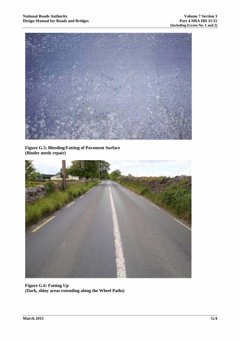
National Roads Authority Volume 7 Section 3 Design Manual for Roads and Bridges Part 4 NRA HD 31/15
(Including Errata No. 1 and 2)
March 2015 G/4
Figure G.5: Bleeding/Fatting of Pavement Surface (Binder needs repair)
Figure G.6: Fatting Up (Dark, shiny areas extending along the Wheel Paths)

National Roads Authority Volume 7 Section 3 Design Manual for Roads and Bridges Part 4 NRA HD 31/15
(Including Errata No. 1 and 2)
March 2015 G/5
Figure G.7: Fatting Up (Dark, shiny areas show where binder has worked to surface)
PAVEMENT DEFORMATION
Rutting
G.3 Rutting is a permanent longitudinal deformation in the wheel paths caused by traffic loading. It occurs due to the displacement of material, creating channels in the wheel paths. Some uplift may also occur along the sides of the rut. It is caused by traffic compaction or sideways movement of unstable material. Severe rutting (over 50mm) may be caused by base or subgrade consolidation. It is a form of structural failure caused by repeated traffic loading.

National Roads Authority Volume 7 Section 3 Design Manual for Roads and Bridges Part 4 NRA HD 31/15
(Including Errata No. 1 and 2)
March 2015 G/6
Figure G.8: Severe Rutting (Over 50mm in depth evident in wheel path)
Figure G.9: Severe Rutting (Caused by poor base or subgrade problems)
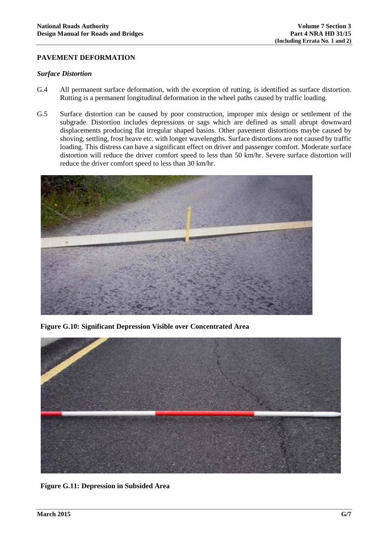
National Roads Authority Volume 7 Section 3 Design Manual for Roads and Bridges Part 4 NRA HD 31/15
(Including Errata No. 1 and 2)
March 2015 G/7
PAVEMENT DEFORMATION
Surface Distortion
G.4 All permanent surface deformation, with the exception of rutting, is identified as surface distortion. Rutting is a permanent longitudinal deformation in the wheel paths caused by traffic loading.
G.5 Surface distortion can be caused by poor construction, improper mix design or settlement of the subgrade. Distortion includes depressions or sags which are defined as small abrupt downward displacements producing flat irregular shaped basins. Other pavement distortions maybe caused by shoving, settling, frost heave etc. with longer wavelengths. Surface distortions are not caused by traffic loading. This distress can have a significant effect on driver and passenger comfort. Moderate surface distortion will reduce the driver comfort speed to less than 50 km/hr. Severe surface distortion will reduce the driver comfort speed to less than 30 km/hr.
Figure G.10: Significant Depression Visible over Concentrated Area
Figure G.11: Depression in Subsided Area

National Roads Authority Volume 7 Section 3 Design Manual for Roads and Bridges Part 4 NRA HD 31/15
(Including Errata No. 1 and 2)
March 2015 G/8
Figure G.12: Surface Distortion (Note road marking on left edge)
Figure G.13: Surface Deformation and Shape Problems (Note road marking on left edge for reference)

National Roads Authority Volume 7 Section 3 Design Manual for Roads and Bridges Part 4 NRA HD 31/15
(Including Errata No. 1 and 2)
March 2015 G/9
CRACKS
Alligator Cracking
G.6 Alligator cracking is a series of interconnected cracks forming small, many-sided, sharp-angled polygons ranging in size from about 25mm to 125mm resembling chicken wire or the skin of an alligator. It’s caused by fatigue failure of the surface due to traffic loading and very often also due to inadequate base or subgrade support. Alligator cracking may comprise:
a) Fine, longitudinal hairline cracks running parallel to each other and with none or only a few interconnecting cracks. There is no spalling which is a breakdown of material along the sides of a crack.
b) A pattern of parallel and interconnecting cracks that may be lightly spalled.
c) A well-defined pattern of interconnected polygon shaped cracks which are spalled at the edges. Some pieces may appear to be loose or may appear to rock under traffic.
Figure G.14: Characteristic “Chicken wire” Crack (Pattern shows Smaller Pavement Pieces and Patching)

National Roads Authority Volume 7 Section 3 Design Manual for Roads and Bridges Part 4 NRA HD 31/15
(Including Errata No. 1 and 2)
March 2015 G/10
Figure G.15: Open Alligator Cracking with Settlement along Lane Edge (Most likely due to very weak subgrade)
Figure G.16: Wide area of Alligator Cracking

National Roads Authority Volume 7 Section 3 Design Manual for Roads and Bridges Part 4 NRA HD 31/15
(Including Errata No. 1 and 2)
March 2015 G/11
CRACKS
Edge Breakup/Cracking
G.7 Edge breakup can be caused by inadequate pavement width, inadequate lateral support to the pavement, moisture penetration, poor drainage or frost action. It is accelerated by repeated traffic loading. Edge breakup is identified as:
a) Any singular or multiple cracking within 300 mm of the pavement edge.
b) Pavement edge showing considerable breakup with some portions of the edge having been removed.
c) Breakup of the pavement edge including a mix of potholing, cracking and patching along the pavement edge.
G.8 Edge breakup differs from loss of surface (Ravelling) at the pavement edge as it is a structural distress caused by traffic loading. Edge breakup can be distinguished from Ravelling by the presence of cracking and loss of some or all the underlying pavement layers at the pavement edge.
G.9 Multiple longitudinal cracks in the pavement edge indicate a need for strengthening with an overlay or reconstruction.
Figure G.17 Edge Breakup (Identified by cracking at the edge of the road pavement)

National Roads Authority Volume 7 Section 3 Design Manual for Roads and Bridges Part 4 NRA HD 31/15
(Including Errata No. 1 and 2)
March 2015 G/12
Figure G.18: Edge Breakup (At the edge of the road pavement)
Figure G.19: Edge Breakup/Cracking and Material Loss (From weakened sub-base and traffic loads)
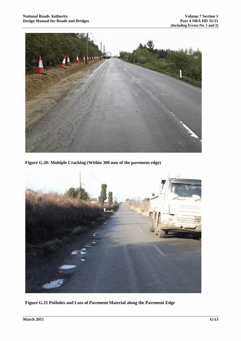
National Roads Authority Volume 7 Section 3 Design Manual for Roads and Bridges Part 4 NRA HD 31/15
(Including Errata No. 1 and 2)
March 2015 G/13
Figure G.20: Multiple Cracking (Within 300 mm of the pavement edge)
Figure G.21 Potholes and Loss of Pavement Material along the Pavement Edge

National Roads Authority Volume 7 Section 3 Design Manual for Roads and Bridges Part 4 NRA HD 31/15
(Including Errata No. 1 and 2)
March 2015 G/14
CRACKS
Other Cracking
G.10 Longitudinal cracks are parallel to the pavement centreline. Transverse cracks extend across the pavement at approximately right angles to the pavement centreline and are often regularly spaced. Transverse cracking at regular, short intervals will often be seen on boggy ground.
G.11 These types of cracking can be caused by reflection cracking from cracking or joints in the underlying pavement layers or by movement of the underlying layers due to moisture penetration, temperature changes, binder hardening due to ageing or traffic loading. The crack edges can further deteriorate by ravelling, eventually eroding the adjacent pavement.
G.12 Other cracking also includes Slippage cracking which are crescent or rounded cracks. They are caused by slippage between an overlay and the underlying pavement due to a low-strength surface mix or poor bond. Slippage is most likely to occur at areas where traffic is stopping and starting, turning or braking.
Figure G.22 Regular Pattern of Transverse Cracking (Bleeding also evident in the Wheel Paths)

National Roads Authority Volume 7 Section 3 Design Manual for Roads and Bridges Part 4 NRA HD 31/15
(Including Errata No. 1 and 2)
March 2015 G/15
Figure G.23: Slippage Cracking with Underlying Stability Problems
Figure G.24: Combined Transverse and Longitudinal Cracking

National Roads Authority Volume 7 Section 3 Design Manual for Roads and Bridges Part 4 NRA HD 31/15
(Including Errata No. 1 and 2)
March 2015 G/16
Patching
G.13 A patch is an area of pavement which has been replaced with new material to repair the original pavement. This indicates a pavement defect or utility cut excavation which has been repaired. Patches with cracking, settlement or distortions indicate underlying causes still remain. Patches may be in good condition and performing satisfactorily, moderately deteriorating or badly deteriorating with other defects in the patched area and in need of replacement.
Figure G.25 Typical Patching Repair of Utility Excavation
Figure G.26 Large Patching in Reasonably Good Condition

National Roads Authority Volume 7 Section 3 Design Manual for Roads and Bridges Part 4 NRA HD 31/15
(Including Errata No. 1 and 2)
March 2015 G/17
Figure G.27 Extensive Patching in Very Poor Condition
Figure G.28 Very Poor/failed Patching with Potholes and Structural Distress Evident

National Roads Authority Volume 7 Section 3 Design Manual for Roads and Bridges Part 4 NRA HD 31/15
(Including Errata No. 1 and 2)
March 2015 G/18
Potholes
G.14 Potholes are bowl-shaped depressions where part of the pavement has been removed, exposing the underlying layer(s). They are produced when cracking or some other defect allows moisture to penetrate the pavement surface, which is subjected to repeated traffic loading. This results in disintegration of the surface and the progressive removal of the underlying material. This is often combined with poor drainage. Repair by excavating or rebuilding localised potholes as well as localised surface dressing/overlay of repaired areas. Reconstruction required for extensive defects.
Figure G.29 Large Isolated Pothole (Extends through base and note adjacent alligator cracks which commonly deteriorate into potholes)
Figure G.30 Re-occuring Potholes due to Poor Patching Work

National Roads Authority Volume 7 Section 3 Design Manual for Roads and Bridges Part 4 NRA HD 31/15
(Including Errata No. 1 and 2)
March 2015 G/19
Road Disintegration
G.15 Road disintegration is identified in two primary forms:
a) Loss of road surface resulting in unbound surfacing materials (gravel or stone).
b) Breakup of road into craters with less than 50% of the road width available to road traffic. The road is no longer passable at speeds above walking pace.
Figure G.31 Road Not Passable by Vehicles at Speeds above Walking Pace. (Damage to vehicles may occur)
Figure G.32 Disintegration of Pavement Resulting in Exposure of Sub-base Materials

Ionad Ghnó Gheata na Páirce,Stráid Gheata na Páirce,Baile Átha Cliath 8, D08 DK10, Éire
www.tii.ie
Parkgate Business Centre,Parkgate Street,Dublin 8, D08 DK10, Ireland
+353 (01) 646 3600
+353 (01) 646 3601