Embed Size (px)
Citation preview
[ 1 ] OTS-4788.7
PART F
((MATERIAL HANDLING,)) STORAGE,
USE, AND DISPOSAL
PART F-1
RIGGING REQUIREMENTS FOR MATERIAL HANDLING
NEW SECTION
WAC 296-155-336 Rigging requirements for material handling.
NEW SECTION
WAC 296-155-33600 Scope. (1) This part applies to
material/load handling activities when using slings, rigging
hardware, below-the-hook lifting devices when performing
construction activities.
(2) This part does not apply to power-operated cranes and
derricks when performing construction activities that fall under
the scope of Part L of this chapter.
NEW SECTION
WAC 296-155-33605 Definitions. Angle of loading means theacute angle between horizontal and the leg of the rigging, often
referred to as horizontal angle. See Figures 7 and 22.
Anti two-block device means a device that, when activated,disengages all crane functions whose movement can cause two-
blocking.
Basket hitch means a method of rigging a sling in which the
[ 2 ] OTS-4788.7
sling is passed around the load and both loop eyes or end fittings
are attached to the lifting device.
Below-the-hook lifting device means a device used for
attaching loads to a hoist. The device may contain components such
as slings, hooks, rigging hardware, and lifting attachments.
Bird caging means the twisting of fiber or wire rope in anisolated area of the rope in the opposite direction of the rope
lay, thereby causing it to take on the appearance of a bird cage.
Braided wire rope means a wire rope formed by plaiting
component wire ropes.
Bridle wire rope sling means a sling composed of multiple legswith the top ends gathered in a fitting that goes over the lifting
hook.
Cable laid endless sling-mechanical joint means a wire ropesling made endless from one continuous length of cable laid rope
with the ends joined by one or more metallic fittings.
Cable laid grommet-hand tucked means an endless wire ropesling made from one continuous length of rope formed to make a body
composed of six ropes around a rope core. The rope ends are tucked
into the body, thus forming the core. No sleeves are used.
Center of gravity means the center of gravity of any object isthe point in the object around which its weight is evenly
distributed. If you could put a support under that point, you
could balance the object on the support.
Choker hitch means a method of rigging a sling in which thesling is passed around the load, then through one loop eye, end
fitting, or other device, with the other loop eye or end fitting
attached to the lifting device. This hitch can be done with a
sliding choker hook or similar device.
Come-a-long means a mechanical device typically consisting ofa chain or cable attached at each end that is used to facilitate
movement of materials through leverage.
Competent person means one who is capable of identifying
existing and predictable hazards in the surroundings or working
conditions which are unsanitary, hazardous, or dangerous to
employees, and who has authorization to take prompt corrective
measures to eliminate them.
Cross rod means a wire used to join spirals of metal mesh toform a complete fabric. See Figure 11.
Design factor means the ratio between nominal or minimum
breaking strength and rated load.
Electrical contact means when a person, object, or equipmentmakes contact or comes close in proximity with an energized
conductor or equipment that allows the passage of current.
Fabric (metal mesh) means the flexible portion of the slingexclusive of end fittings consisting of a series of transverse
spirals and cross rods.
Fall zone means the area (including, but not limited to, thearea directly beneath the load) in which it is reasonably
foreseeable that partially or completely suspended materials could
fall in the event of an accident.
Flange points means a point of contact between rope and drum
[ 3 ] OTS-4788.7
flange where the rope changes layers.
Hitch (hitched) means a method of rigging (attaching) a slingtemporarily to a load or object for the purpose of lifting.
Hoist means a mechanical device for lifting and lowering loadsby winding rope onto or off a drum.
Hoisting means the act of raising, lowering or otherwise
moving a load in the air with equipment covered by this standard.
As used in this standard, "hoisting" can be done by means other
than wire rope/hoist drum equipment.
Hoisting equipment means a machine for lifting and lowering aload and moving it horizontally. The machine may be fixed or
mobile and be driven manually, by power, or by a combination of
both.
Hook latch means a mechanical device used to close the throatopening of a hook.
Load is the weight of the object being lifted or lowered,including the weight of the load-attaching equipment such as the
load block, ropes, slings, shackles, and any other auxiliary
attachment.
Load ratings means a set of rated loads for stipulated
hoisting equipment configurations and operating conditions.
Master coupling link means an alloy steel welded coupling linkused as an intermediate link to join alloy steel chain to master
links.
Master link means forged or welded steel link used to supportall members (legs) of an alloy steel chain sling or wire rope
sling.
Mechanical coupling link (alloy steel chain) means a
nonwelded, mechanically closed link used primarily to attach
fittings to alloy steel chain.
Operational controls means levers, switches, pedals and otherdevices for controlling equipment operation.
Procedures include, but are not limited to: Instructions,diagrams, recommendations, warnings, specifications, protocols, and
limitations.
Qualified person means a person who, by possession of a
recognized degree, certificate, or professional standing, or who by
extensive knowledge, training and experience, successfully
demonstrated the ability to solve/resolve problems relating to the
subject matter, the work, or the project.
Qualified rigger is a rigger who meets the requirements in WAC296-155-33700.
Rated capacity means the maximum working load permitted by themanufacturer under specified working conditions. Such working
conditions typically include a specific combination of factors such
as equipment configuration, radii, boom length, and other
parameters of use.
Rotation resistant rope means a type of wire rope constructionwhich reduces the tendency of a rope to rotate about its axis under
load. Usually, this consists of an inner system of core strands
laid in one direction covered by an outer system of strands laid in
the opposite direction.
[ 4 ] OTS-4788.7
RPE means a registered professional engineer licensed underRCW 18.43.040(1).
RPSE means a registered professional structural engineer
licensed under RCW 18.43.040(1).
Running wire rope is a wire rope that moves over sheaves ordrums.
Safety or health standard means a standard adopted under thischapter.
Section means a section of this part, unless otherwise
specified.
Sling means an assembly to be used for lifting when connectedto a lifting mechanism. The upper portion of the sling is
connected to the lifting mechanism and the lower supports the load,
as described in this part.
Spiral means a single transverse coil that is the basic
element from which metal mesh is fabricated.
Standing wire rope means a supporting wire rope which
maintains a constant distance between the points of attachment to
the two components connected by the wire rope.
Two blocking means a condition in which a component that isuppermost on the hoist line such as the load block, hook block,
overhaul ball, or similar component, comes in contact with the boom
tip, fixed upper block or similar component. This binds the system
and continued application of power can cause failure of the hoist
rope or other component.
Vertical hitch means a method of rigging a sling in which theload is attached to the loop eye or end fitting at one end of the
sling and the loop eye or end fitting at the other end is attached
to the lifting device. Any hitch less than five degrees from the
vertical may be considered a vertical hitch.
Wire rope means a flexible rope constructed by laying steelwires into various patterns of multiwired strands around a core
system to produce a helically wound rope.
Working load means the external load applied to the hoistingequipment, including the personnel lifting platform, its contents,
and the load attaching equipment, such as lowered load block,
shackles, and slings.
NEW SECTION
WAC 296-155-337 Rigging--General requirements.
[ 5 ] OTS-4788.7
NEW SECTION
WAC 296-155-33700 Rigger qualifications. Riggers must be aqualified person who, by possession of a recognized degree or
certificate of professional standing, or who, by extensive
knowledge, training, and experience, has successfully demonstrated
the ability to solve or resolve problems relating the subject
matter. Also has the authorization or authority by the nature of
their position to take prompt corrective measures to eliminate
them. The person must be knowledgeable in the requirements of this
part as applicable to the tasks assigned, including but not limited
to:
! "Know and understand of the requirements for slings, rigging
hardware, and below-the-hook lifting devices, including their
limitations, rigging practices, associated hazards, and inspection
requirements;
! "Know and understand the application of the type of hitches
used;
! "Know and understand load weight estimation, center of
gravity, effect of angle on rigging components, and load turning.
NEW SECTION
WAC 296-155-33705 General requirements. (1) Employers mustensure all rigging activities covered under this part are performed
by a qualified rigger or performed under the direction and
supervision of a qualified rigger.
(2) All slings in use must meet the applicable requirements
for design, inspection, construction, testing, maintenance and
operation as prescribed in ASME B30.9-2010.
(3) All rigging hardware in use must meet the applicable
requirements for design, inspection, construction, testing,
maintenance and operation as prescribed in ASME B30.26-2010.
(4) All rigging gear must be used in accordance with the
manufacturer's recommendations or a qualified person.
(5) All below-the-hook lifting devices in use must meet the
applicable requirements for design, inspection, construction,
testing, maintenance and operation as prescribed in ASME B30.20-
2010.
(6) All hooks in use must meet the applicable requirements for
design, inspection, construction, testing, maintenance and
operation as prescribed in ASME B30.10-2009.
(7) Repair of hooks must be approved by the manufacturer or
qualified person and as follows:
(a) Cracks, nicks, and gouges may be repaired by a competent
person, all other repairs are done by the manufacturer or a
qualified person;
(b) Grind longitudinally, following the contour of the hook;
[ 6 ] OTS-4788.7
(c) Do not reduce the dimension of the hook more than ten
percent from the original.
(8) Hooks must not be modified by welding and/or drilling
unless written approval by the manufacturer has been received.
(9) A qualified person must inspect the rigging equipment
before each day or shift and:
(a) Consider the application the equipment will be used for,
and determine if it's safe for use;
(b) Remove the equipment from service if using it will create
a hazard or meets any of the removal criteria listed in this
chapter.
(10) The rated load of the rigging equipment must not be
exceeded.
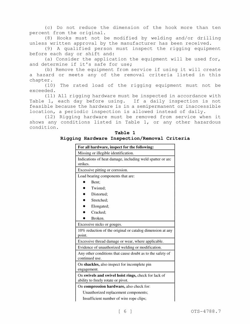
(11) All rigging hardware must be inspected in accordance with
Table 1, each day before using. If a daily inspection is not
feasible because the hardware is in a semipermanent or inaccessible
location, a periodic inspection is allowed instead of daily.
(12) Rigging hardware must be removed from service when it
shows any conditions listed in Table 1, or any other hazardous
condition.
Table 1
Rigging Hardware Inspection/Removal Criteria
For all hardware, inspect for the following:
Missing or illegible identification.
Indications of heat damage, including weld spatter or arc
strikes.
Excessive pitting or corrosion.
Load bearing components that are:
! Bent;
! Twisted;
! Distorted;
! Stretched;
! Elongated;
! Cracked;
! Broken.
Excessive nicks or gouges.
10% reduction of the original or catalog dimension at any
point.
Excessive thread damage or wear, where applicable.
Evidence of unauthorized welding or modification.
Any other conditions that cause doubt as to the safety of
continued use.
On shackles, also inspect for incomplete pin
engagement.
On swivels and swivel hoist rings, check for lack of
ability to freely rotate or pivot.
On compression hardware, also check for:
Unauthorized replacement components;
Insufficient number of wire rope clips;
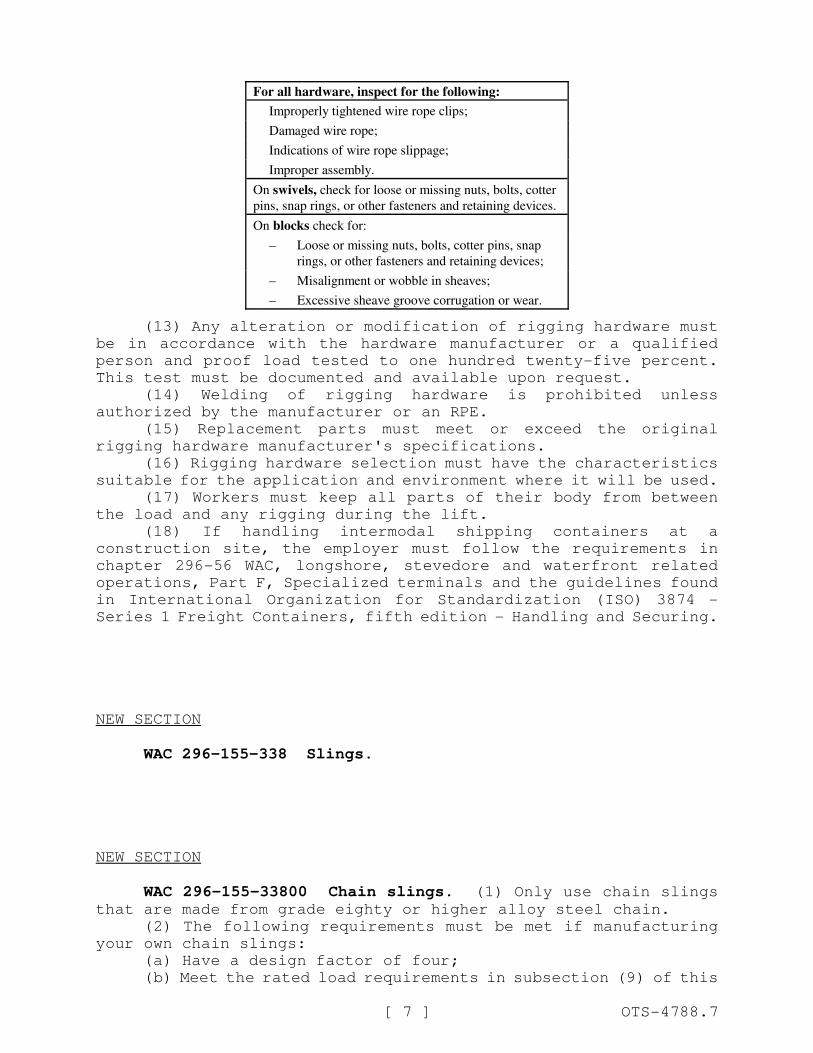
For all hardware, inspect for the following:
[ 7 ] OTS-4788.7
Improperly tightened wire rope clips;
Damaged wire rope;
Indications of wire rope slippage;
Improper assembly.
On swivels, check for loose or missing nuts, bolts, cotter
pins, snap rings, or other fasteners and retaining devices.
On blocks check for:
– Loose or missing nuts, bolts, cotter pins, snap
rings, or other fasteners and retaining devices;
– Misalignment or wobble in sheaves;
– Excessive sheave groove corrugation or wear.
(13) Any alteration or modification of rigging hardware must
be in accordance with the hardware manufacturer or a qualified
person and proof load tested to one hundred twenty-five percent.
This test must be documented and available upon request.
(14) Welding of rigging hardware is prohibited unless
authorized by the manufacturer or an RPE.
(15) Replacement parts must meet or exceed the original
rigging hardware manufacturer's specifications.
(16) Rigging hardware selection must have the characteristics
suitable for the application and environment where it will be used.
(17) Workers must keep all parts of their body from between
the load and any rigging during the lift.
(18) If handling intermodal shipping containers at a
construction site, the employer must follow the requirements in
chapter 296-56 WAC, longshore, stevedore and waterfront related
operations, Part F, Specialized terminals and the guidelines found
in International Organization for Standardization (ISO) 3874 -
Series 1 Freight Containers, fifth edition - Handling and Securing.
NEW SECTION
WAC 296-155-338 Slings.
NEW SECTION
WAC 296-155-33800 Chain slings. (1) Only use chain slingsthat are made from grade eighty or higher alloy steel chain.
(2) The following requirements must be met if manufacturing
your own chain slings:
(a) Have a design factor of four;
(b) Meet the rated load requirements in subsection (9) of this
[ 8 ] OTS-4788.7
section.
(3) Rate chain slings with the load capacity of the lowest
rated component of the sling. For example, if you use fittings
that are rated lower than the sling material itself, identify the
sling with the lower rated capacity.
(4) Makeshift fittings, such as hooks or links formed from
bolts, rods, or other parts are prohibited.
(5) All chain slings must have legible identification
information attached to the sling which includes the following
information:
(a) Name or trademark of the manufacturer;
(b) Grade;
(c) Nominal chain size;
(d) Number of legs;
(e) Rated loads for the vertical hitch and bridle hitch and
the angle upon which it is based;
(f) Length (reach);
(g) Individual sling identification (e.g., serial numbers);
(h) Repairing agency, if the sling was ever repaired.
(6) Inspections.
(a) A qualified person must inspect chain slings before their
initial use, according to Table 2, both:
(i) When the sling is new; and
(ii) Whenever a repair, alteration, or modification has been
done.
(b) A qualified person must perform a visual inspection for
damage, each day or shift the chain sling is used. Immediately
remove from service any sling damaged beyond the criteria in Table
2.
(c) A qualified person must perform periodic inspections on
chain slings according to Table 2.
(i) Each link and component must be examined individually,
taking care to expose and examine all surfaces including the inner
link surfaces.
(ii) Remove slings from use:
! If any of the conditions in Table 2 are found;
! When they have been exposed to temperatures above one
thousand degrees Fahrenheit.
(d) A written record of the most recent periodic inspection
must be kept, including the condition of the sling.
Note: An external code mark on the sling is an acceptable means of recording the inspection as long as the code can be traced
back to a record.
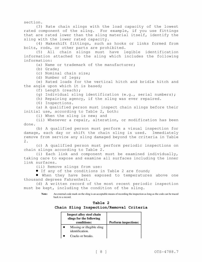
Table 2
Chain Sling Inspection/Removal Criteria
Inspect alloy steel chain
slings for the following
conditions: Perform inspections:
! Missing or illegible sling
identification.
! Cracks or breaks.
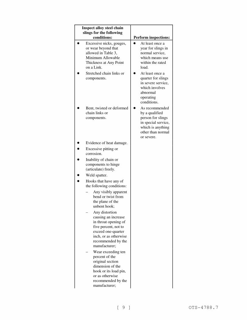
Inspect alloy steel chain
slings for the following
conditions: Perform inspections:
[ 9 ] OTS-4788.7
! Excessive nicks, gouges,
or wear beyond that
allowed in Table 3,
Minimum Allowable
Thickness at Any Point
on a Link.
! At least once a
year for slings in
normal service,
which means use
within the rated
load.
! Stretched chain links or
components.
! At least once a
quarter for slings
in severe service,
which involves
abnormal
operating
conditions.
! Bent, twisted or deformed
chain links or
components.
! As recommended
by a qualified
person for slings
in special service,
which is anything
other than normal
or severe.
! Evidence of heat damage.
! Excessive pitting or
corrosion.
! Inability of chain or
components to hinge
(articulate) freely.
! Weld spatter.
! Hooks that have any of
the following conditions:
– Any visibly apparent
bend or twist from
the plane of the
unbent hook;
– Any distortion
causing an increase
in throat opening of
five percent, not to
exceed one-quarter
inch, or as otherwise
recommended by the
manufacturer;
– Wear exceeding ten
percent of the
original section
dimension of the
hook or its load pin,
or as otherwise
recommended by the
manufacturer;
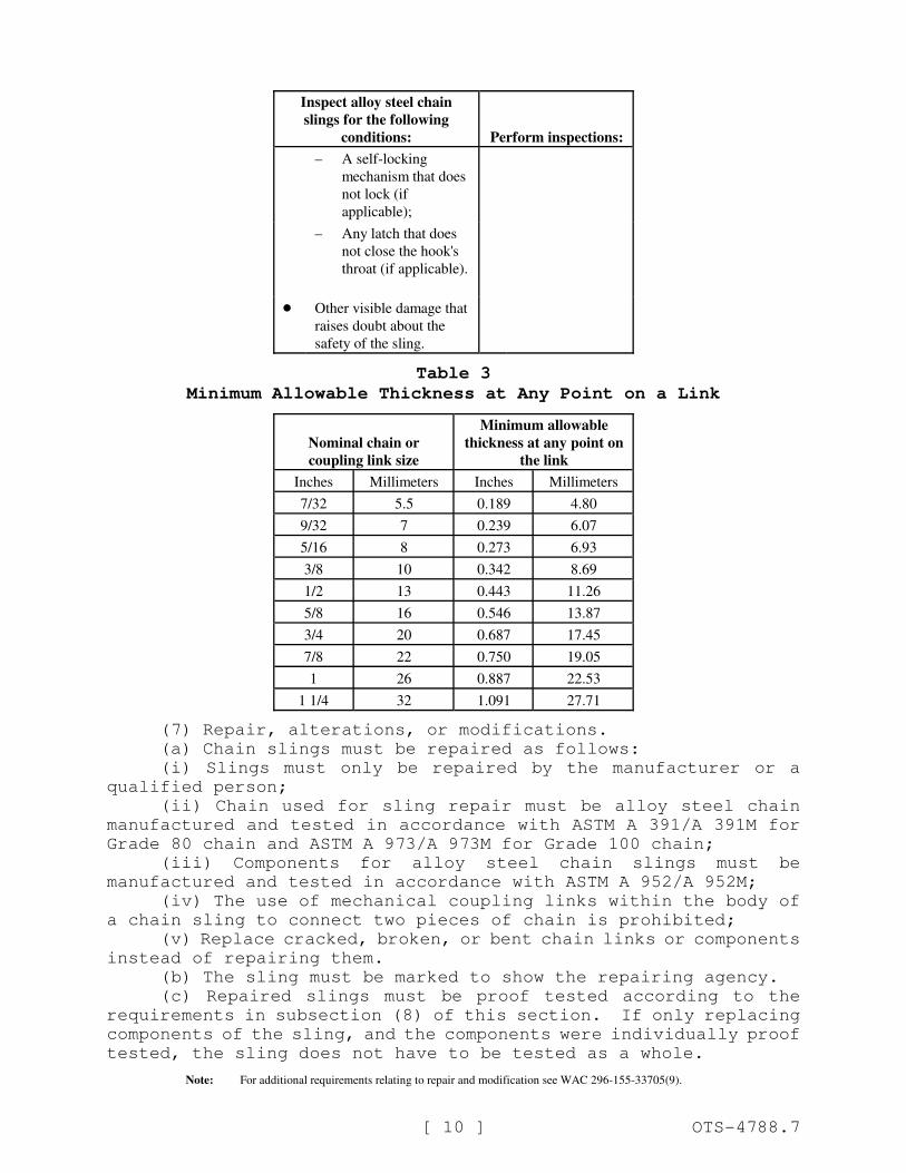
Inspect alloy steel chain
slings for the following
conditions: Perform inspections:
[ 10 ] OTS-4788.7
– A self-locking
mechanism that does
not lock (if
applicable);
– Any latch that does
not close the hook's
throat (if applicable).
! Other visible damage that
raises doubt about the
safety of the sling.
Table 3
Minimum Allowable Thickness at Any Point on a Link
Nominal chain or
coupling link size
Minimum allowable
thickness at any point on
the link
Inches Millimeters Inches Millimeters
7/32 5.5 0.189 4.80
9/32 7 0.239 6.07
5/16 8 0.273 6.93
3/8 10 0.342 8.69
1/2 13 0.443 11.26
5/8 16 0.546 13.87
3/4 20 0.687 17.45
7/8 22 0.750 19.05
1 26 0.887 22.53
1 1/4 32 1.091 27.71
(7) Repair, alterations, or modifications.
(a) Chain slings must be repaired as follows:
(i) Slings must only be repaired by the manufacturer or a
qualified person;
(ii) Chain used for sling repair must be alloy steel chain
manufactured and tested in accordance with ASTM A 391/A 391M for
Grade 80 chain and ASTM A 973/A 973M for Grade 100 chain;
(iii) Components for alloy steel chain slings must be
manufactured and tested in accordance with ASTM A 952/A 952M;
(iv) The use of mechanical coupling links within the body of
a chain sling to connect two pieces of chain is prohibited;
(v) Replace cracked, broken, or bent chain links or components
instead of repairing them.
(b) The sling must be marked to show the repairing agency.
(c) Repaired slings must be proof tested according to the
requirements in subsection (8) of this section. If only replacing
components of the sling, and the components were individually proof
tested, the sling does not have to be tested as a whole.
Note: For additional requirements relating to repair and modification see WAC 296-155-33705(9).
[ 11 ] OTS-4788.7
(8) Proof test chain slings. Prior to initial use, all new
and repaired chain and components of an alloy steel chain sling,
either individually or as an assembly must be proof tested by the
sling manufacturer or a qualified person. Follow the requirements
in Table 4, Chain Sling Proof Load Requirements.
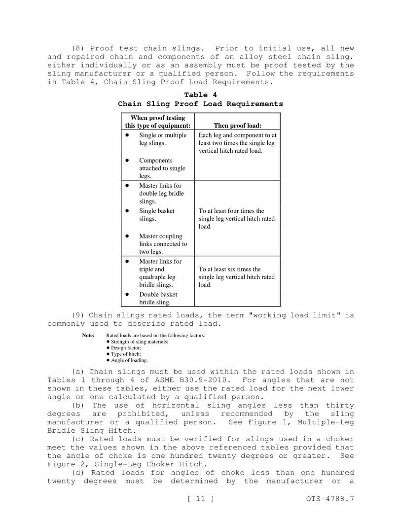
Table 4
Chain Sling Proof Load Requirements
When proof testing
this type of equipment: Then proof load:
! Single or multiple
leg slings.
Each leg and component to at
least two times the single leg
vertical hitch rated load.
! Components
attached to single
legs.
! Master links for
double leg bridle
slings.
! Single basket
slings.
To at least four times the
single leg vertical hitch rated
load.
! Master coupling
links connected to
two legs.
! Master links for
triple and
quadruple leg
bridle slings.
To at least six times the
single leg vertical hitch rated
load.
! Double basket
bridle sling.
(9) Chain slings rated loads, the term "working load limit" is
commonly used to describe rated load.
Note: Rated loads are based on the following factors:
! Strength of sling materials;
! Design factor;
! Type of hitch;
! Angle of loading.
(a) Chain slings must be used within the rated loads shown in
Tables 1 through 4 of ASME B30.9-2010. For angles that are not
shown in these tables, either use the rated load for the next lower
angle or one calculated by a qualified person.
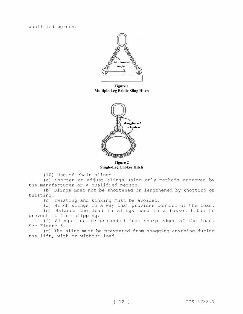
(b) The use of horizontal sling angles less than thirty
degrees are prohibited, unless recommended by the sling
manufacturer or a qualified person. See Figure 1, Multiple-Leg
Bridle Sling Hitch.
(c) Rated loads must be verified for slings used in a choker
meet the values shown in the above referenced tables provided that
the angle of choke is one hundred twenty degrees or greater. See
Figure 2, Single-Leg Choker Hitch.
(d) Rated loads for angles of choke less than one hundred
twenty degrees must be determined by the manufacturer or a
[ 12 ] OTS-4788.7
qualified person.
Figure 1
Multiple-Leg Bridle Sling Hitch
Figure 2
Single-Leg Choker Hitch
(10) Use of chain slings.
(a) Shorten or adjust slings using only methods approved by
the manufacturer or a qualified person.
(b) Slings must not be shortened or lengthened by knotting or
twisting.
(c) Twisting and kinking must be avoided.
(d) Hitch slings in a way that provides control of the load.
(e) Balance the load in slings used in a basket hitch to
prevent it from slipping.
(f) Slings must be protected from sharp edges of the load.
See Figure 3.
(g) The sling must be prevented from snagging anything during
the lift, with or without load.

[ 13 ] OTS-4788.7
Softeners can be made from split pipe, padding or blocking
Figure 3
Softeners
NEW SECTION
WAC 296-155-33805 Wire rope slings. (1) Manufacturing wirerope slings.
(a) Wire rope slings must be made from new or unused regular
lay wire rope. The wire rope must be manufactured and tested in
accordance with ASTM A 1023-02 and ASTM A 586.
(b) The following fabrication methods must be used to make
wire rope slings:
(i) Hand splicing;
(ii) Turnback eye;
(iii) Return loop;
(iv) Flemish eye mechanical splicing;
(v) Poured or swaged socketing.
(c) Wire rope slings must have a design factor of five.
(d) Wire rope slings must meet the requirements in Table 6.
(e) Using any of the following when making wire rope slings is
prohibited:
(i) Rotation resistant wire rope;
(ii) Malleable cast iron clips;
(iii) Knots;
(iv) Wire rope clips, unless:
! The application of the sling prevents using prefabricated
slings;
! The specific application is designed by a qualified person.
(f) Wire rope clips, if used, must be installed and maintained
in accordance with the recommendations of the clip manufacturer or
a qualified person, or in accordance with the provisions of ASME
B30.26-2010.
(g) Slings made with wire rope clips must not be used as a
choker hitch.
[ 14 ] OTS-4788.7
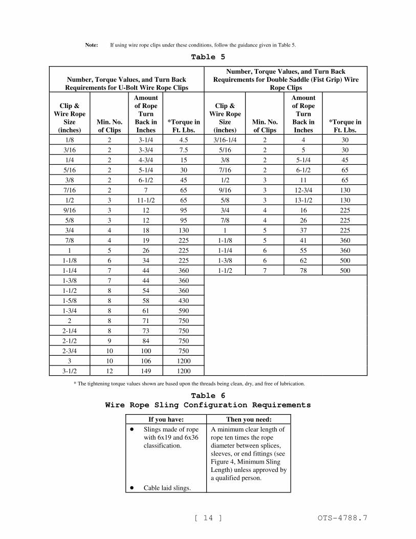
Note: If using wire rope clips under these conditions, follow the guidance given in Table 5.
Table 5
Number, Torque Values, and Turn Back
Requirements for U-Bolt Wire Rope Clips
Number, Torque Values, and Turn Back
Requirements for Double Saddle (Fist Grip) Wire
Rope Clips
Clip &
Wire Rope
Size
(inches)
Min. No.
of Clips
Amount
of Rope
Turn
Back in
Inches
.*Torque in
Ft. Lbs.
Clip &
Wire Rope
Size
(inches)
Min. No.
of Clips
Amount
of Rope
Turn
Back in
Inches
.*Torque in
Ft. Lbs.
1/8 2 3-1/4 4.5 3/16-1/4 2 4 30
3/16 2 3-3/4 7.5 5/16 2 5 30
1/4 2 4-3/4 15 3/8 2 5-1/4 45
5/16 2 5-1/4 30 7/16 2 6-1/2 65
3/8 2 6-1/2 45 1/2 3 11 65
7/16 2 7 65 9/16 3 12-3/4 130
1/2 3 11-1/2 65 5/8 3 13-1/2 130
9/16 3 12 95 3/4 4 16 225
5/8 3 12 95 7/8 4 26 225
3/4 4 18 130 1 5 37 225
7/8 4 19 225 1-1/8 5 41 360
1 5 26 225 1-1/4 6 55 360
1-1/8 6 34 225 1-3/8 6 62 500
1-1/4 7 44 360 1-1/2 7 78 500
1-3/8 7 44 360
1-1/2 8 54 360
1-5/8 8 58 430
1-3/4 8 61 590
2 8 71 750
2-1/4 8 73 750
2-1/2 9 84 750
2-3/4 10 100 750
3 10 106 1200
3-1/2 12 149 1200
.* The tightening torque values shown are based upon the threads being clean, dry, and free of lubrication.
Table 6
Wire Rope Sling Configuration Requirements
If you have: Then you need:
! Slings made of rope
with 6x19 and 6x36
classification.
A minimum clear length of
rope ten times the rope
diameter between splices,
sleeves, or end fittings (see
Figure 4, Minimum Sling
Length) unless approved by
a qualified person.
! Cable laid slings.
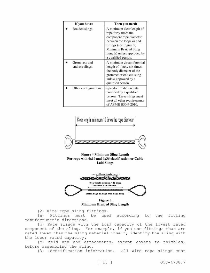
If you have: Then you need:
[ 15 ] OTS-4788.7
! Braided slings. A minimum clear length of
rope forty times the
component rope diameter
between the loops or end
fittings (see Figure 5,
Minimum Braided Sling
Length) unless approved by
a qualified person.
! Grommets and
endless slings.
A minimum circumferential
length of ninety-six times
the body diameter of the
grommet or endless sling
unless approved by a
qualified person.
! Other configurations. Specific limitation data
provided by a qualified
person. These slings must
meet all other requirements
of ASME B30.9-2010.
Figure 4 Minimum Sling Length
For rope with 6x19 and 6x36 classification or Cable
Laid Slings
Figure 5
Minimum Braided Sling Length
(2) Wire rope sling fittings.
(a) Fittings must be used according to the fitting
manufacturer's directions.
(b) Rate slings with the load capacity of the lowest rated
component of the sling. For example, if you use fittings that are
rated lower than the sling material itself, identify the sling with
the lower rated capacity.
(c) Weld any end attachments, except covers to thimbles,
before assembling the sling.
(3) Identification information. All wire rope slings must
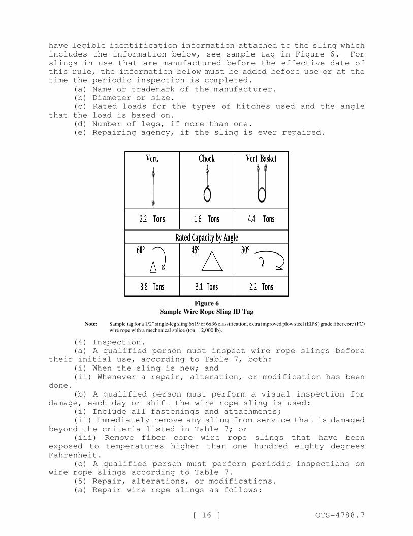
[ 16 ] OTS-4788.7
have legible identification information attached to the sling which
includes the information below, see sample tag in Figure 6. For
slings in use that are manufactured before the effective date of
this rule, the information below must be added before use or at the
time the periodic inspection is completed.
(a) Name or trademark of the manufacturer.
(b) Diameter or size.
(c) Rated loads for the types of hitches used and the angle
that the load is based on.
(d) Number of legs, if more than one.
(e) Repairing agency, if the sling is ever repaired.
Figure 6
Sample Wire Rope Sling ID Tag
Note: Sample tag for a 1/2" single-leg sling 6x19 or 6x36 classification, extra improved plow steel (EIPS) grade fiber core (FC)
wire rope with a mechanical splice (ton .= 2,000 lb).
(4) Inspection.
(a) A qualified person must inspect wire rope slings before
their initial use, according to Table 7, both:
(i) When the sling is new; and
(ii) Whenever a repair, alteration, or modification has been
done.
(b) A qualified person must perform a visual inspection for
damage, each day or shift the wire rope sling is used:
(i) Include all fastenings and attachments;
(ii) Immediately remove any sling from service that is damaged
beyond the criteria listed in Table 7; or
(iii) Remove fiber core wire rope slings that have been
exposed to temperatures higher than one hundred eighty degrees
Fahrenheit.
(c) A qualified person must perform periodic inspections on
wire rope slings according to Table 7.
(5) Repair, alterations, or modifications.
(a) Repair wire rope slings as follows:
[ 17 ] OTS-4788.7
(i) Make sure slings are only repaired by the sling
manufacturer or a qualified person;
(ii) Mark the sling to show the repairing agency;
(iii) Do not repair wire rope used in slings, wire rope must
be replaced. Only end attachments and fittings can be repaired on
a wire rope sling.
(b) Modification or alterations to end attachments or fittings
must be considered as repairs and must conform to all other
provisions of this part.
(c) Proof load test repaired slings according to the
requirements in subsection (6) of this section.
(6) Proof load tests. Make sure the sling manufacturer or a
qualified person proof load tests the following slings before
initial use, according to Table 8:
(a) All repaired slings;
(b) All slings incorporating previously used or welded
fittings;
(c) For single- or multiple-leg slings and endless slings,
each leg must be proof loaded according to the requirements listed
in Table 8 based on fabrication method. The proof load test must
not exceed fifty percent of the component ropes' or structural
strands' minimum breaking strength;
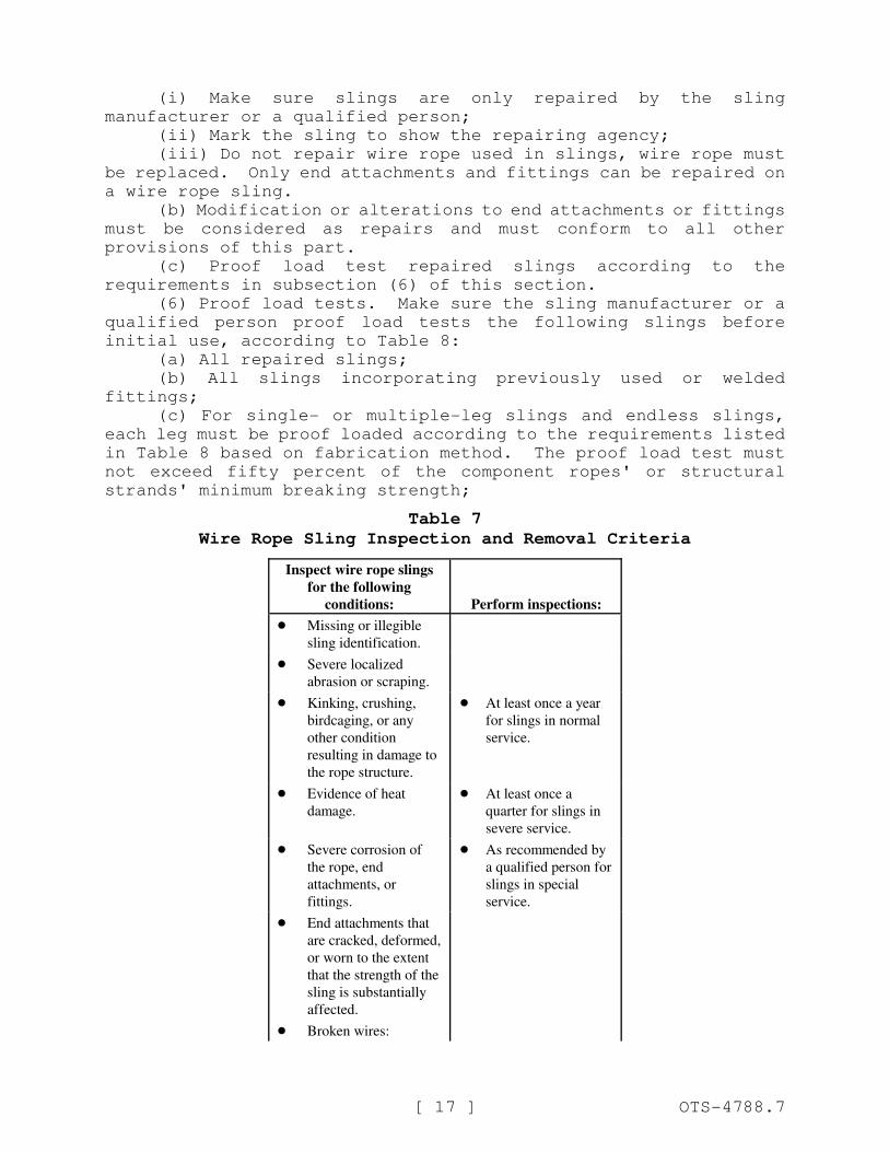
Table 7
Wire Rope Sling Inspection and Removal Criteria
Inspect wire rope slings
for the following
conditions: Perform inspections:
! Missing or illegible
sling identification.
! Severe localized
abrasion or scraping.
! Kinking, crushing,
birdcaging, or any
other condition
resulting in damage to
the rope structure.
! At least once a year
for slings in normal
service.
! Evidence of heat
damage.
! At least once a
quarter for slings in
severe service.
! Severe corrosion of
the rope, end
attachments, or
fittings.
! As recommended by
a qualified person for
slings in special
service.
! End attachments that
are cracked, deformed,
or worn to the extent
that the strength of the
sling is substantially
affected.
! Broken wires:

Inspect wire rope slings
for the following
conditions: Perform inspections:
[ 18 ] OTS-4788.7
– For strand-laid and
single-part slings,
ten randomly
distributed broken
wires in one rope
lay, or five broken
wires in one strand
in one rope lay;
– For cable-laid
slings, twenty
broken wires per
lay;
– For six-part braided
slings, twenty
broken wires per
braid;
– For eight-part
braided slings,
forty broken wires
per braid.
! Hooks that have any
of the following
conditions:
– Any visibly
apparent bend or
twist from the plane
of the unbent hook;
– Any distortion
causing an increase
in throat opening
five percent, not to
exceed one-quarter
inch, or as
recommended by
the manufacturer;
– Wear exceeding ten
percent, of the
original section
dimension of the
hook or its load
pin, or as
recommended by
the manufacturer;
– Self-locking
mechanism that
does not lock.
! Other visible damage
that raises doubt about
the safety of the sling.
Table 8
[ 19 ] OTS-4788.7
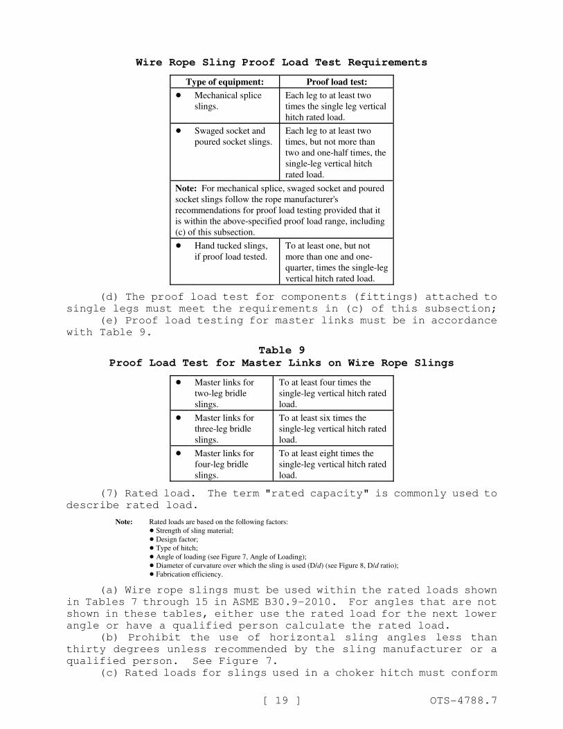
Wire Rope Sling Proof Load Test Requirements
Type of equipment: Proof load test:
! Mechanical splice
slings.
Each leg to at least two
times the single leg vertical
hitch rated load.
! Swaged socket and
poured socket slings.
Each leg to at least two
times, but not more than
two and one-half times, the
single-leg vertical hitch
rated load.
Note: For mechanical splice, swaged socket and poured
socket slings follow the rope manufacturer's
recommendations for proof load testing provided that it
is within the above-specified proof load range, including
(c) of this subsection.
! Hand tucked slings,
if proof load tested.
To at least one, but not
more than one and one-
quarter, times the single-leg
vertical hitch rated load.
(d) The proof load test for components (fittings) attached to
single legs must meet the requirements in (c) of this subsection;
(e) Proof load testing for master links must be in accordance
with Table 9.
Table 9
Proof Load Test for Master Links on Wire Rope Slings
! Master links for
two-leg bridle
slings.
To at least four times the
single-leg vertical hitch rated
load.
! Master links for
three-leg bridle
slings.
To at least six times the
single-leg vertical hitch rated
load.
! Master links for
four-leg bridle
slings.
To at least eight times the
single-leg vertical hitch rated
load.
(7) Rated load. The term "rated capacity" is commonly used to
describe rated load.
Note: Rated loads are based on the following factors:
! Strength of sling material;
! Design factor;
! Type of hitch;
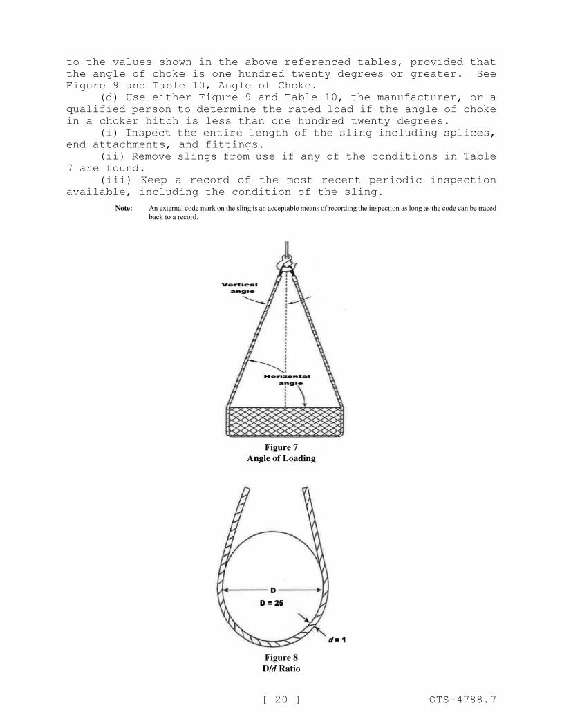
! Angle of loading (see Figure 7, Angle of Loading);
! Diameter of curvature over which the sling is used (D/d) (see Figure 8, D/d ratio);
! Fabrication efficiency.
(a) Wire rope slings must be used within the rated loads shown
in Tables 7 through 15 in ASME B30.9-2010. For angles that are not
shown in these tables, either use the rated load for the next lower
angle or have a qualified person calculate the rated load.
(b) Prohibit the use of horizontal sling angles less than
thirty degrees unless recommended by the sling manufacturer or a
qualified person. See Figure 7.
(c) Rated loads for slings used in a choker hitch must conform
[ 20 ] OTS-4788.7
to the values shown in the above referenced tables, provided that
the angle of choke is one hundred twenty degrees or greater. See
Figure 9 and Table 10, Angle of Choke.
(d) Use either Figure 9 and Table 10, the manufacturer, or a
qualified person to determine the rated load if the angle of choke
in a choker hitch is less than one hundred twenty degrees.
(i) Inspect the entire length of the sling including splices,
end attachments, and fittings.
(ii) Remove slings from use if any of the conditions in Table
7 are found.
(iii) Keep a record of the most recent periodic inspection
available, including the condition of the sling.
Note: An external code mark on the sling is an acceptable means of recording the inspection as long as the code can be traced
back to a record.
Figure 7
Angle of Loading
Figure 8
D/d Ratio
[ 21 ] OTS-4788.7
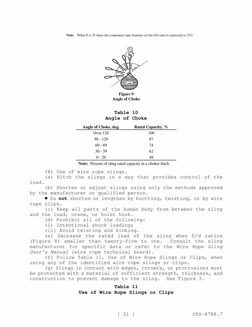
Note: When D is 25 times the component rope diameter (d) the D/d ratio is expressed as 25/1.
Figure 9
Angle of Choke
Table 10
Angle of Choke
Angle of Choke, deg. Rated Capacity, %
Over 120 100
90 - 120 87
60 - 89 74
30 - 59 62
0 - 29 49
Note: Percent of sling rated capacity in a choker hitch.
(8) Use of wire rope slings.
(a) Hitch the slings in a way that provides control of the
load.
(b) Shorten or adjust slings using only the methods approved
by the manufacturer or qualified person.
! Do not shorten or lengthen by knotting, twisting, or by wirerope clips.
(c) Keep all parts of the human body from between the sling
and the load, crane, or hoist hook.
(d) Prohibit all of the following:
(i) Intentional shock loading;
(ii) Avoid twisting and kinking.
(e) Decrease the rated load of the sling when D/d ratios
(Figure 8) smaller than twenty-five to one. Consult the sling
manufacturer for specific data or refer to the Wire Rope Sling
User's Manual (wire rope technical board).
(f) Follow Table 11, Use of Wire Rope Slings or Clips, when
using any of the identified wire rope slings or clips.
(g) Slings in contact with edges, corners, or protrusions must
be protected with a material of sufficient strength, thickness, and
construction to prevent damage to the sling. See Figure 3.
Table 11
Use of Wire Rope Slings or Clips
[ 22 ] OTS-4788.7
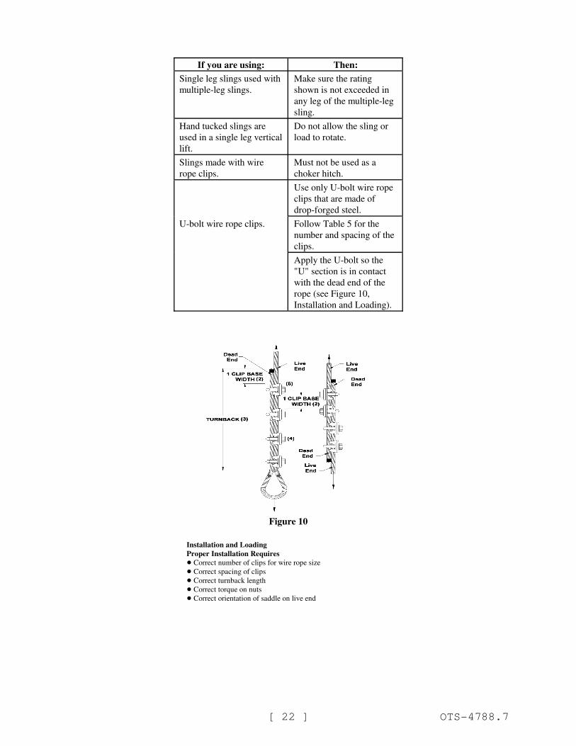
If you are using: Then:
Single leg slings used with
multiple-leg slings.
Make sure the rating
shown is not exceeded in
any leg of the multiple-leg
sling.
Hand tucked slings are
used in a single leg vertical
lift.
Do not allow the sling or
load to rotate.
Slings made with wire
rope clips.
Must not be used as a
choker hitch.
Use only U-bolt wire rope
clips that are made of
drop-forged steel.
U-bolt wire rope clips. Follow Table 5 for the
number and spacing of the
clips.
Apply the U-bolt so the
"U" section is in contact
with the dead end of the
rope (see Figure 10,
Installation and Loading).
Figure 10
Installation and Loading
Proper Installation Requires
! Correct number of clips for wire rope size
! Correct spacing of clips
! Correct turnback length
! Correct torque on nuts
! Correct orientation of saddle on live end
[ 23 ] OTS-4788.7
NEW SECTION
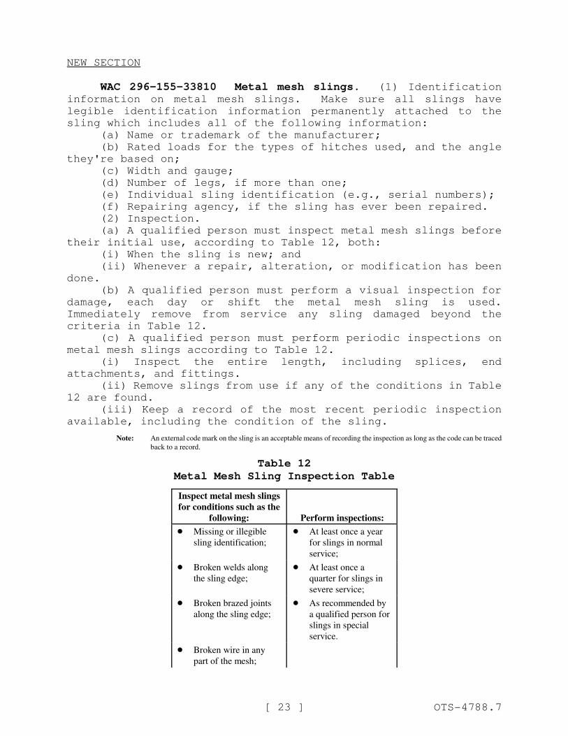
WAC 296-155-33810 Metal mesh slings. (1) Identificationinformation on metal mesh slings. Make sure all slings have
legible identification information permanently attached to the
sling which includes all of the following information:
(a) Name or trademark of the manufacturer;
(b) Rated loads for the types of hitches used, and the angle
they're based on;
(c) Width and gauge;
(d) Number of legs, if more than one;
(e) Individual sling identification (e.g., serial numbers);
(f) Repairing agency, if the sling has ever been repaired.
(2) Inspection.
(a) A qualified person must inspect metal mesh slings before
their initial use, according to Table 12, both:
(i) When the sling is new; and
(ii) Whenever a repair, alteration, or modification has been
done.
(b) A qualified person must perform a visual inspection for
damage, each day or shift the metal mesh sling is used.
Immediately remove from service any sling damaged beyond the
criteria in Table 12.
(c) A qualified person must perform periodic inspections on
metal mesh slings according to Table 12.
(i) Inspect the entire length, including splices, end
attachments, and fittings.
(ii) Remove slings from use if any of the conditions in Table
12 are found.
(iii) Keep a record of the most recent periodic inspection
available, including the condition of the sling.
Note: An external code mark on the sling is an acceptable means of recording the inspection as long as the code can be traced
back to a record.
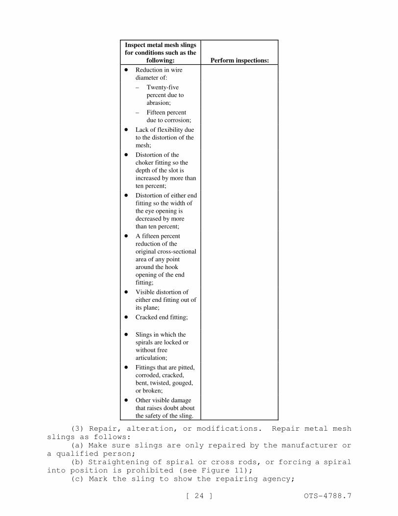
Table 12
Metal Mesh Sling Inspection Table
Inspect metal mesh slings
for conditions such as the
following: Perform inspections:
! Missing or illegible
sling identification;
! At least once a year
for slings in normal
service;
! Broken welds along
the sling edge;
! At least once a
quarter for slings in
severe service;
! Broken brazed joints
along the sling edge;
! As recommended by
a qualified person for
slings in special
service.
! Broken wire in any
part of the mesh;
Inspect metal mesh slings
for conditions such as the
following: Perform inspections:
[ 24 ] OTS-4788.7
! Reduction in wire
diameter of:
– Twenty-five
percent due to
abrasion;
– Fifteen percent
due to corrosion;
! Lack of flexibility due
to the distortion of the
mesh;
! Distortion of the
choker fitting so the
depth of the slot is
increased by more than
ten percent;
! Distortion of either end
fitting so the width of
the eye opening is
decreased by more
than ten percent;
! A fifteen percent
reduction of the
original cross-sectional
area of any point
around the hook
opening of the end
fitting;
! Visible distortion of
either end fitting out of
its plane;
! Cracked end fitting;
! Slings in which the
spirals are locked or
without free
articulation;
! Fittings that are pitted,
corroded, cracked,
bent, twisted, gouged,
or broken;
! Other visible damage
that raises doubt about
the safety of the sling.
(3) Repair, alteration, or modifications. Repair metal mesh
slings as follows:
(a) Make sure slings are only repaired by the manufacturer or
a qualified person;
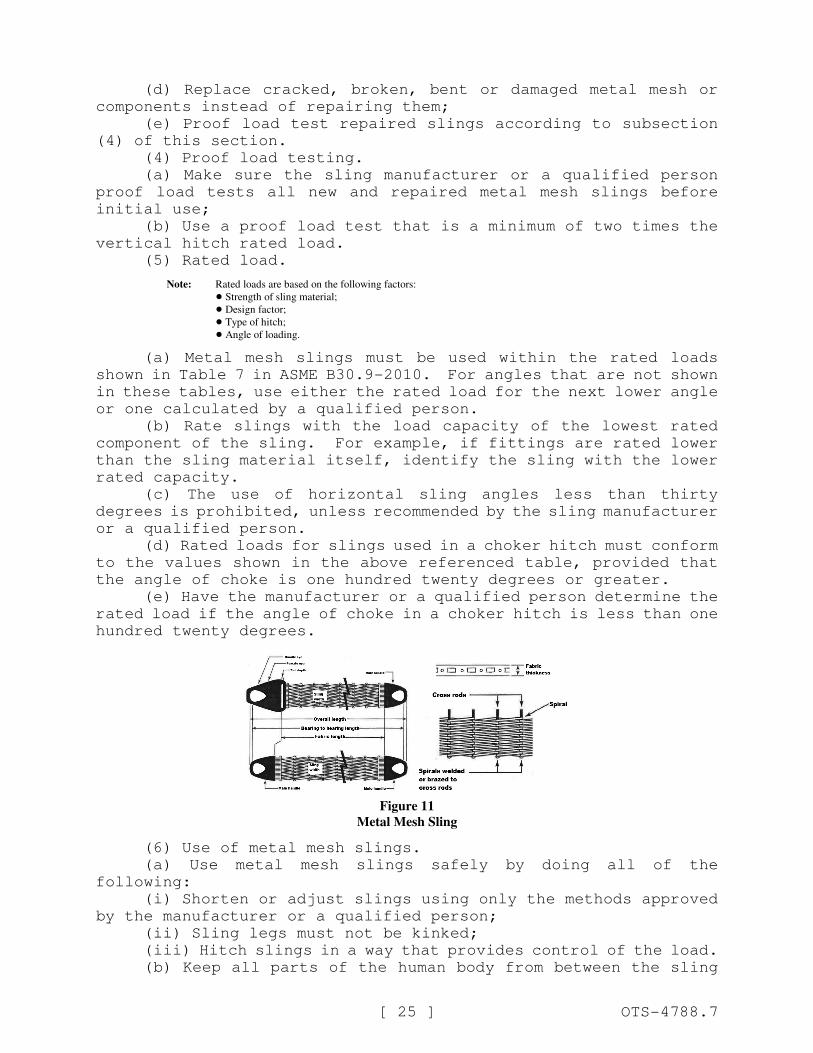
(b) Straightening of spiral or cross rods, or forcing a spiral
into position is prohibited (see Figure 11);
(c) Mark the sling to show the repairing agency;
[ 25 ] OTS-4788.7
(d) Replace cracked, broken, bent or damaged metal mesh or
components instead of repairing them;
(e) Proof load test repaired slings according to subsection
(4) of this section.
(4) Proof load testing.
(a) Make sure the sling manufacturer or a qualified person
proof load tests all new and repaired metal mesh slings before
initial use;
(b) Use a proof load test that is a minimum of two times the
vertical hitch rated load.
(5) Rated load.
Note: Rated loads are based on the following factors:
! Strength of sling material;
! Design factor;
! Type of hitch;
! Angle of loading.
(a) Metal mesh slings must be used within the rated loads
shown in Table 7 in ASME B30.9-2010. For angles that are not shown
in these tables, use either the rated load for the next lower angle
or one calculated by a qualified person.
(b) Rate slings with the load capacity of the lowest rated
component of the sling. For example, if fittings are rated lower
than the sling material itself, identify the sling with the lower
rated capacity.
(c) The use of horizontal sling angles less than thirty
degrees is prohibited, unless recommended by the sling manufacturer
or a qualified person.
(d) Rated loads for slings used in a choker hitch must conform
to the values shown in the above referenced table, provided that
the angle of choke is one hundred twenty degrees or greater.
(e) Have the manufacturer or a qualified person determine the
rated load if the angle of choke in a choker hitch is less than one
hundred twenty degrees.
Figure 11
Metal Mesh Sling
(6) Use of metal mesh slings.
(a) Use metal mesh slings safely by doing all of the
following:
(i) Shorten or adjust slings using only the methods approved
by the manufacturer or a qualified person;
(ii) Sling legs must not be kinked;
(iii) Hitch slings in a way that provides control of the load.
(b) Keep all parts of the human body from between the sling
[ 26 ] OTS-4788.7
and the load, crane, or hoist hook.
(c) Prohibit the following:
(i) The use of metal mesh slings as bridles on suspended
personnel platforms;
(ii) Intentional shock loading;
(iii) Straightening a spiral or cross rod or forcing a spiral
into position;
(iv) Avoid twisting and kinking.
Note: Slings in contact with edges, corners, or protrusions should be protected with a material of sufficient strength, thickness,
and construction to prevent damage. See Figure 3.
NEW SECTION
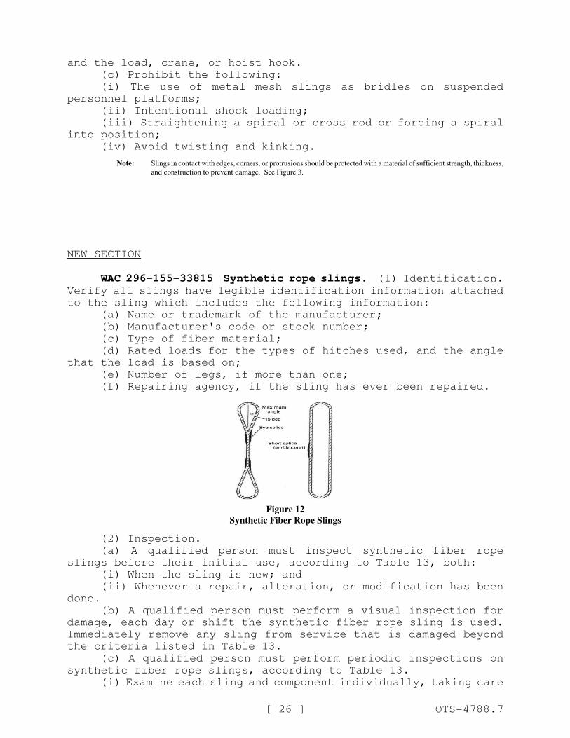
WAC 296-155-33815 Synthetic rope slings. (1) Identification.Verify all slings have legible identification information attached
to the sling which includes the following information:
(a) Name or trademark of the manufacturer;
(b) Manufacturer's code or stock number;
(c) Type of fiber material;
(d) Rated loads for the types of hitches used, and the angle
that the load is based on;
(e) Number of legs, if more than one;
(f) Repairing agency, if the sling has ever been repaired.
Figure 12
Synthetic Fiber Rope Slings
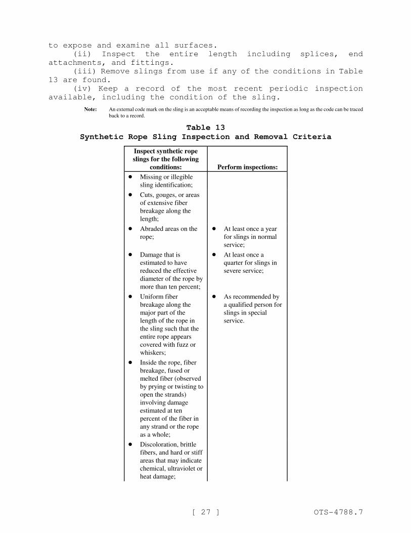
(2) Inspection.
(a) A qualified person must inspect synthetic fiber rope
slings before their initial use, according to Table 13, both:
(i) When the sling is new; and
(ii) Whenever a repair, alteration, or modification has been
done.
(b) A qualified person must perform a visual inspection for
damage, each day or shift the synthetic fiber rope sling is used.
Immediately remove any sling from service that is damaged beyond
the criteria listed in Table 13.
(c) A qualified person must perform periodic inspections on
synthetic fiber rope slings, according to Table 13.
(i) Examine each sling and component individually, taking care
[ 27 ] OTS-4788.7
to expose and examine all surfaces.
(ii) Inspect the entire length including splices, end
attachments, and fittings.
(iii) Remove slings from use if any of the conditions in Table
13 are found.
(iv) Keep a record of the most recent periodic inspection
available, including the condition of the sling.
Note: An external code mark on the sling is an acceptable means of recording the inspection as long as the code can be traced
back to a record.
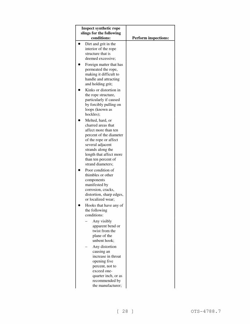
Table 13
Synthetic Rope Sling Inspection and Removal Criteria
Inspect synthetic rope
slings for the following
conditions: Perform inspections:
! Missing or illegible
sling identification;
! Cuts, gouges, or areas
of extensive fiber
breakage along the
length;
! Abraded areas on the
rope;
! At least once a year
for slings in normal
service;
! Damage that is
estimated to have
reduced the effective
diameter of the rope by
more than ten percent;
! At least once a
quarter for slings in
severe service;
! Uniform fiber
breakage along the
major part of the
length of the rope in
the sling such that the
entire rope appears
covered with fuzz or
whiskers;
! As recommended by
a qualified person for
slings in special
service.
! Inside the rope, fiber
breakage, fused or
melted fiber (observed
by prying or twisting to
open the strands)
involving damage
estimated at ten
percent of the fiber in
any strand or the rope
as a whole;
! Discoloration, brittle
fibers, and hard or stiff
areas that may indicate
chemical, ultraviolet or
heat damage;
Inspect synthetic rope
slings for the following
conditions: Perform inspections:
[ 28 ] OTS-4788.7
! Dirt and grit in the
interior of the rope
structure that is
deemed excessive;
! Foreign matter that has
permeated the rope,
making it difficult to
handle and attracting
and holding grit;
! Kinks or distortion in
the rope structure,
particularly if caused
by forcibly pulling on
loops (known as
hockles);
! Melted, hard, or
charred areas that
affect more than ten
percent of the diameter
of the rope or affect
several adjacent
strands along the
length that affect more
than ten percent of
strand diameters;
! Poor condition of
thimbles or other
components
manifested by
corrosion, cracks,
distortion, sharp edges,
or localized wear;
! Hooks that have any of
the following
conditions:
– Any visibly
apparent bend or
twist from the
plane of the
unbent hook;
– Any distortion
causing an
increase in throat
opening five
percent, not to
exceed one-
quarter inch, or as
recommended by
the manufacturer;
Inspect synthetic rope
slings for the following
conditions: Perform inspections:
[ 29 ] OTS-4788.7
– Wear exceeding
ten percent, of the
original section
dimension of the
hook or its load
pin, or as
recommended by
the manufacturer;
– Self-locking
mechanism that
does not lock.
! Other visible damage
that raises doubt about
the safety of the sling.
(3) Repair, alteration, or modifications. Meet the following
requirements when repairing synthetic rope slings:
(a) Synthetic rope slings must only be repaired by the
manufacturer or a qualified person;
(b) Mark the sling to show the repairing agency;
(c) Use components that meet the requirements of this part for
sling repair;
(d) Do not repair slings by knotting or resplicing existing
sling ropes;
(e) Proof load test repaired slings according to the
requirements in subsection (4) of this section.
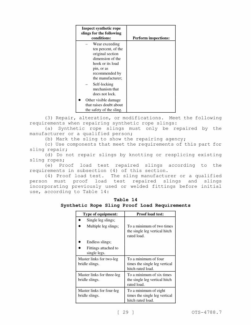
(4) Proof load test. The sling manufacturer or a qualified
person must proof load test repaired slings and slings
incorporating previously used or welded fittings before initial
use, according to Table 14:
Table 14
Synthetic Rope Sling Proof Load Requirements
Type of equipment: Proof load test:
! Single leg slings;
! Multiple leg slings; To a minimum of two times
the single leg vertical hitch
rated load.
! Endless slings;
! Fittings attached to
single legs.
Master links for two-leg
bridle slings.
To a minimum of four
times the single leg vertical
hitch rated load.
Master links for three-leg
bridle slings.
To a minimum of six times
the single leg vertical hitch
rated load.
Master links for four-leg
bridle slings.
To a minimum of eight
times the single leg vertical
hitch rated load.
[ 30 ] OTS-4788.7
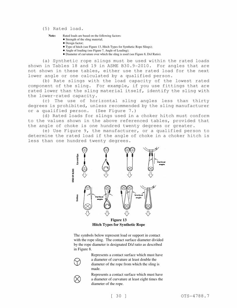
(5) Rated load.
Note: Rated loads are based on the following factors:
! Strength of the sling material;
! Design factor;
! Type of hitch (see Figure 13, Hitch Types for Synthetic Rope Slings);
! Angle of loading (see Figure 7, Angle of Loading);
! Diameter of curvature over which the sling is used (see Figure 8, D/d Ratio).
(a) Synthetic rope slings must be used within the rated loads
shown in Tables 18 and 19 in ASME B30.9-2010. For angles that are
not shown in these tables, either use the rated load for the next
lower angle or one calculated by a qualified person.
(b) Rate slings with the load capacity of the lowest rated
component of the sling. For example, if you use fittings that are
rated lower than the sling material itself, identify the sling with
the lower-rated capacity.
(c) The use of horizontal sling angles less than thirty
degrees is prohibited, unless recommended by the sling manufacturer
or a qualified person. (See Figure 7.)
(d) Rated loads for slings used in a choker hitch must conform
to the values shown in the above referenced tables, provided that
the angle of choke is one hundred twenty degrees or greater.
(e) Use Figure 9, the manufacturer, or a qualified person to
determine the rated load if the angle of choke in a choker hitch is
less than one hundred twenty degrees.
Figure 13
Hitch Types for Synthetic Rope
The symbols below represent load or support in contact
with the rope sling. The contact surface diameter divided
by the rope diameter is designated D/d ratio as described
in Figure 8.
Represents a contact surface which must have
a diameter of curvature at least double the
diameter of the rope from which the sling is
made.
Represents a contact surface which must have
a diameter of curvature at least eight times the
diameter of the rope.
[ 31 ] OTS-4788.7
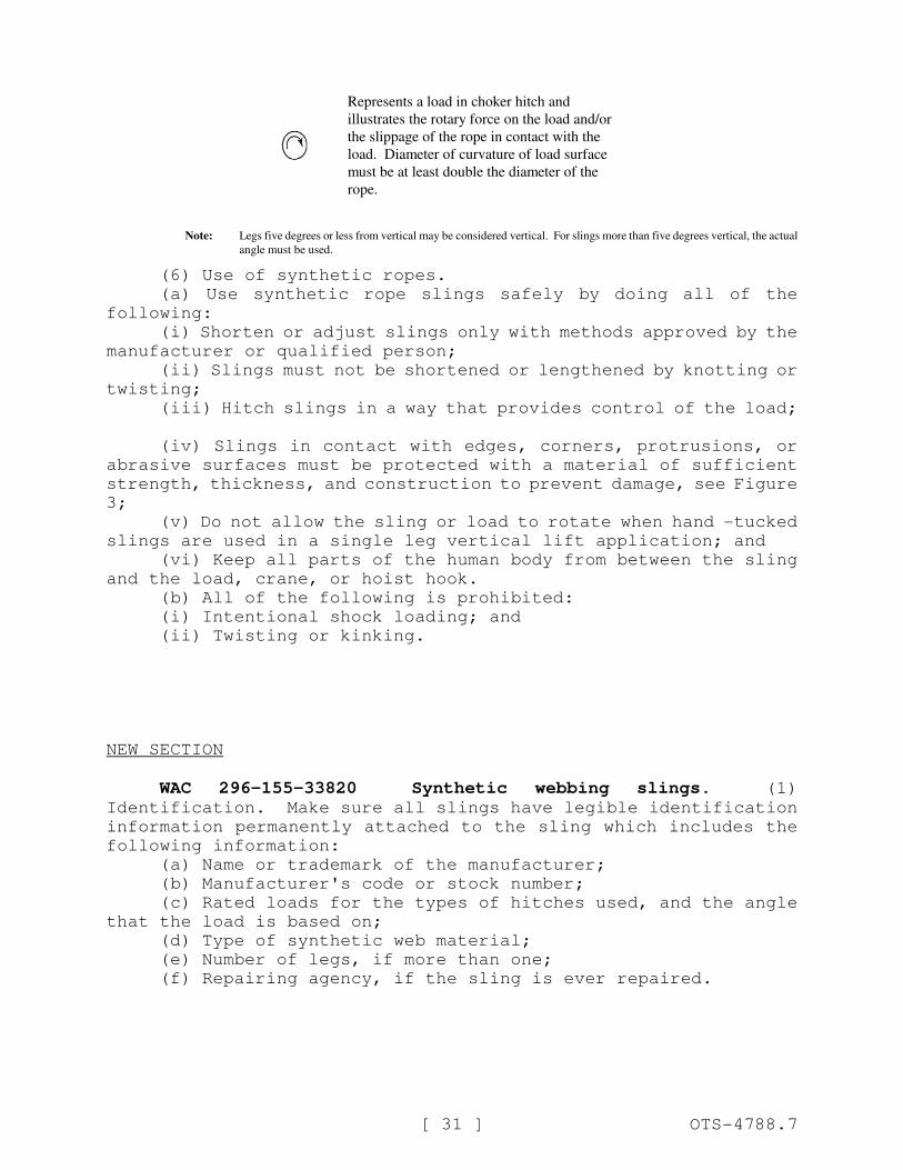
Represents a load in choker hitch and
illustrates the rotary force on the load and/or
the slippage of the rope in contact with the
load. Diameter of curvature of load surface
must be at least double the diameter of the
rope.
Note: Legs five degrees or less from vertical may be considered vertical. For slings more than five degrees vertical, the actual
angle must be used.
(6) Use of synthetic ropes.
(a) Use synthetic rope slings safely by doing all of the
following:
(i) Shorten or adjust slings only with methods approved by the
manufacturer or qualified person;
(ii) Slings must not be shortened or lengthened by knotting or
twisting;
(iii) Hitch slings in a way that provides control of the load;
(iv) Slings in contact with edges, corners, protrusions, or
abrasive surfaces must be protected with a material of sufficient
strength, thickness, and construction to prevent damage, see Figure
3;
(v) Do not allow the sling or load to rotate when hand -tucked
slings are used in a single leg vertical lift application; and
(vi) Keep all parts of the human body from between the sling
and the load, crane, or hoist hook.
(b) All of the following is prohibited:
(i) Intentional shock loading; and
(ii) Twisting or kinking.
NEW SECTION
WAC 296-155-33820 Synthetic webbing slings. (1)
Identification. Make sure all slings have legible identification
information permanently attached to the sling which includes the
following information:
(a) Name or trademark of the manufacturer;
(b) Manufacturer's code or stock number;
(c) Rated loads for the types of hitches used, and the angle
that the load is based on;
(d) Type of synthetic web material;
(e) Number of legs, if more than one;
(f) Repairing agency, if the sling is ever repaired.
[ 32 ] OTS-4788.7
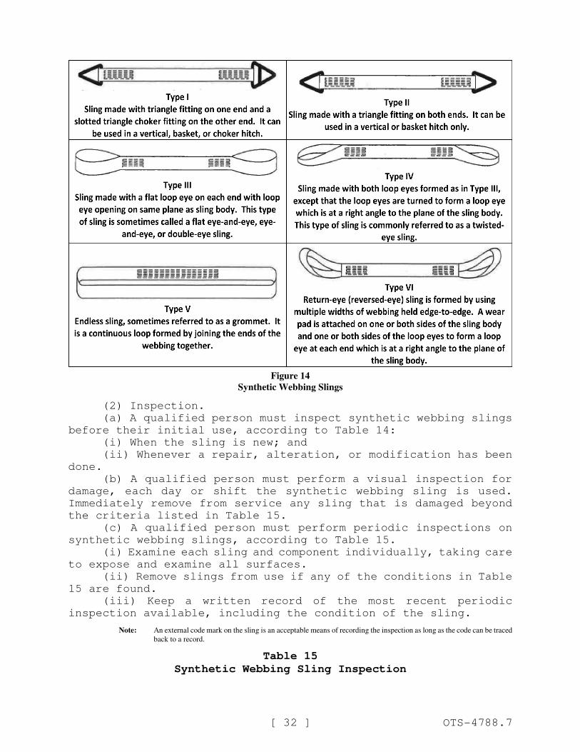
Figure 14
Synthetic Webbing Slings
(2) Inspection.
(a) A qualified person must inspect synthetic webbing slings
before their initial use, according to Table 14:
(i) When the sling is new; and
(ii) Whenever a repair, alteration, or modification has been
done.
(b) A qualified person must perform a visual inspection for
damage, each day or shift the synthetic webbing sling is used.
Immediately remove from service any sling that is damaged beyond
the criteria listed in Table 15.
(c) A qualified person must perform periodic inspections on
synthetic webbing slings, according to Table 15.
(i) Examine each sling and component individually, taking care
to expose and examine all surfaces.
(ii) Remove slings from use if any of the conditions in Table
15 are found.
(iii) Keep a written record of the most recent periodic
inspection available, including the condition of the sling.
Note: An external code mark on the sling is an acceptable means of recording the inspection as long as the code can be traced
back to a record.
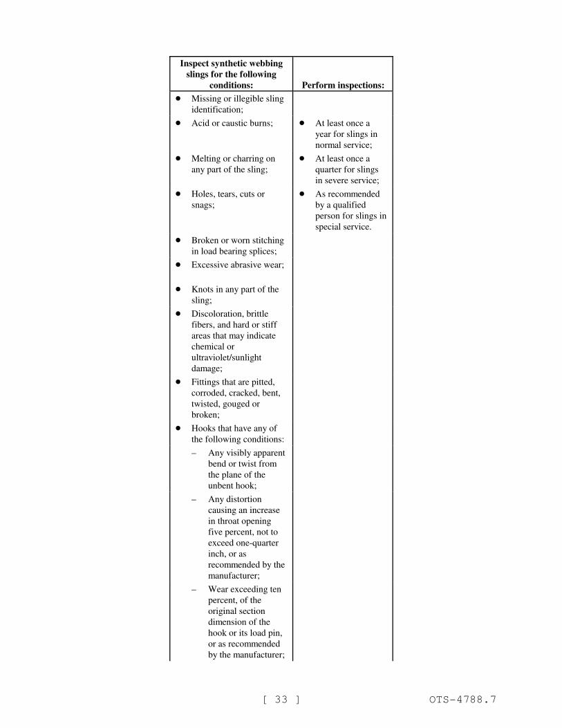
Table 15
Synthetic Webbing Sling Inspection
[ 33 ] OTS-4788.7
Inspect synthetic webbing
slings for the following
conditions: Perform inspections:
! Missing or illegible sling
identification;
! Acid or caustic burns; ! At least once a
year for slings in
normal service;
! Melting or charring on
any part of the sling;
! At least once a
quarter for slings
in severe service;
! Holes, tears, cuts or
snags;
! As recommended
by a qualified
person for slings in
special service.
! Broken or worn stitching
in load bearing splices;
! Excessive abrasive wear;
! Knots in any part of the
sling;
! Discoloration, brittle
fibers, and hard or stiff
areas that may indicate
chemical or
ultraviolet/sunlight
damage;
! Fittings that are pitted,
corroded, cracked, bent,
twisted, gouged or
broken;
! Hooks that have any of
the following conditions:
– Any visibly apparent
bend or twist from
the plane of the
unbent hook;
– Any distortion
causing an increase
in throat opening
five percent, not to
exceed one-quarter
inch, or as
recommended by the
manufacturer;
– Wear exceeding ten
percent, of the
original section
dimension of the
hook or its load pin,
or as recommended
by the manufacturer;

Inspect synthetic webbing
slings for the following
conditions: Perform inspections:
[ 34 ] OTS-4788.7
– Self-locking
mechanism that does
not lock.
! Other visible damage that
causes doubt about the
safety of continued use of
the sling.
(3) Repair, alterations, or modifications.
(a) Meet the following requirements when repairing synthetic
webbing slings:
(i) Slings are only to be repaired by the manufacturer or a
qualified person;
(ii) Temporary repairs are prohibited;
(iii) Mark the sling to show the repairing agency;
(iv) Components used for sling repair must meet the
requirements of this part;
(v) Cracked, broken, melted, or otherwise damaged webbing
material or fittings other than hooks must not be repaired;
(vi) Load bearing splices must not be repaired;
(b) Proof load test repaired slings according to the
requirements in subsection (4) of this section.
(4) Proof load test. The sling manufacturer or a qualified
person must proof load test repaired slings and slings that have
been altered or modified before initial use according to Table 16:
Table 16
Synthetic Webbing Sling Proof Test Requirements
Type of equipment: Proof load test:
!
!
!
!
Single leg slings;
Multiple leg slings;
Endless slings;
Fittings attached to
single legs.
To a minimum of two
times the single leg vertical
hitch rated load.
Master links for two-leg
bridle slings.
To a minimum of four
times the single leg vertical
hitch rated load.
Master links for three-leg
bridle slings.
To a minimum of six times
the single leg vertical hitch
rated load.
Master links for four-leg
bridle slings.
To a minimum of eight
times the single leg vertical
hitch rated load.
(5) Rated loads.
Note: Rated loads are based on the following factors:
! Strength of the material;
[ 35 ] OTS-4788.7
! Design factor;
! Type of hitch;
! Angle of loading (see Figure 7, Angle of Loading);
! Fabrication efficiency;
! Diameter of curvature over which the sling is used.
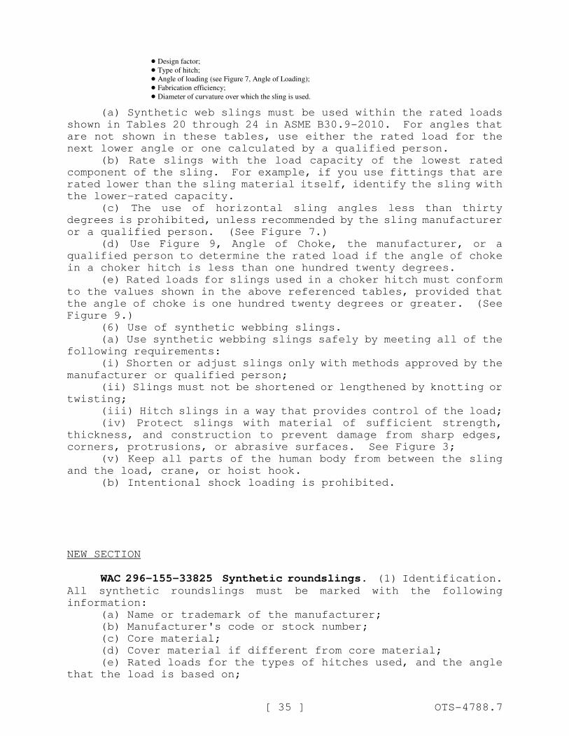
(a) Synthetic web slings must be used within the rated loads
shown in Tables 20 through 24 in ASME B30.9-2010. For angles that
are not shown in these tables, use either the rated load for the
next lower angle or one calculated by a qualified person.
(b) Rate slings with the load capacity of the lowest rated
component of the sling. For example, if you use fittings that are
rated lower than the sling material itself, identify the sling with
the lower-rated capacity.
(c) The use of horizontal sling angles less than thirty
degrees is prohibited, unless recommended by the sling manufacturer
or a qualified person. (See Figure 7.)
(d) Use Figure 9, Angle of Choke, the manufacturer, or a
qualified person to determine the rated load if the angle of choke
in a choker hitch is less than one hundred twenty degrees.
(e) Rated loads for slings used in a choker hitch must conform
to the values shown in the above referenced tables, provided that
the angle of choke is one hundred twenty degrees or greater. (See
Figure 9.)
(6) Use of synthetic webbing slings.
(a) Use synthetic webbing slings safely by meeting all of the
following requirements:
(i) Shorten or adjust slings only with methods approved by the
manufacturer or qualified person;
(ii) Slings must not be shortened or lengthened by knotting or
twisting;
(iii) Hitch slings in a way that provides control of the load;
(iv) Protect slings with material of sufficient strength,
thickness, and construction to prevent damage from sharp edges,
corners, protrusions, or abrasive surfaces. See Figure 3;
(v) Keep all parts of the human body from between the sling
and the load, crane, or hoist hook.
(b) Intentional shock loading is prohibited.
NEW SECTION
WAC 296-155-33825 Synthetic roundslings. (1) Identification.All synthetic roundslings must be marked with the following
information:
(a) Name or trademark of the manufacturer;
(b) Manufacturer's code or stock number;
(c) Core material;
(d) Cover material if different from core material;
(e) Rated loads for the types of hitches used, and the angle
that the load is based on;
[ 36 ] OTS-4788.7
(f) Number of legs, if more than one;
(g) Repairing agency, if the sling is ever repaired.
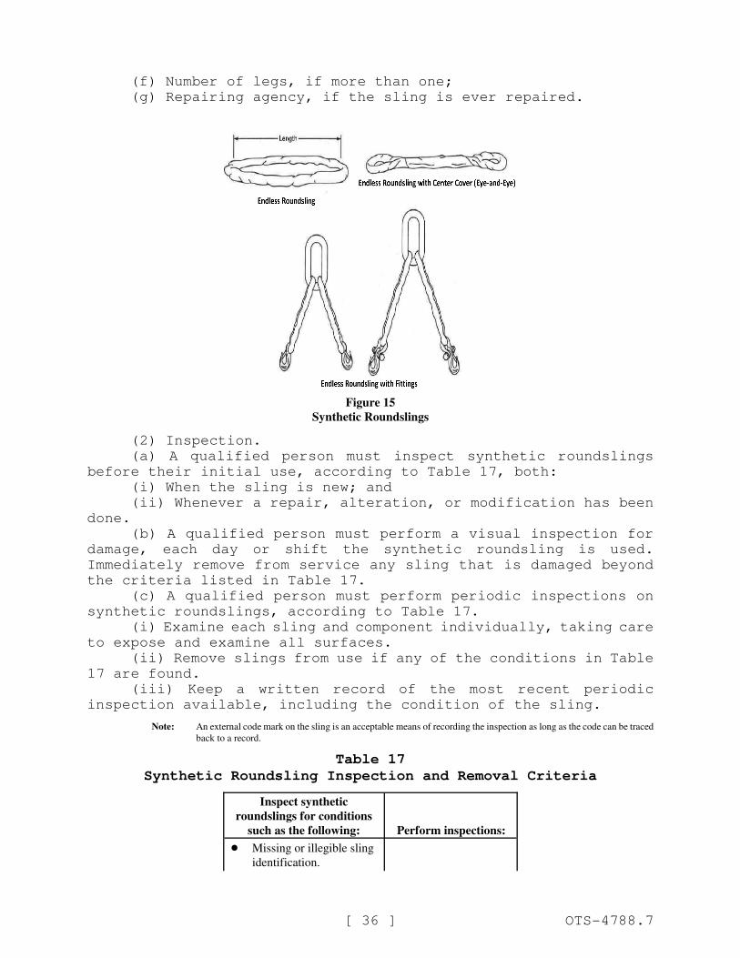
Figure 15
Synthetic Roundslings
(2) Inspection.
(a) A qualified person must inspect synthetic roundslings
before their initial use, according to Table 17, both:
(i) When the sling is new; and
(ii) Whenever a repair, alteration, or modification has been
done.
(b) A qualified person must perform a visual inspection for
damage, each day or shift the synthetic roundsling is used.
Immediately remove from service any sling that is damaged beyond
the criteria listed in Table 17.
(c) A qualified person must perform periodic inspections on
synthetic roundslings, according to Table 17.
(i) Examine each sling and component individually, taking care
to expose and examine all surfaces.
(ii) Remove slings from use if any of the conditions in Table
17 are found.
(iii) Keep a written record of the most recent periodic
inspection available, including the condition of the sling.
Note: An external code mark on the sling is an acceptable means of recording the inspection as long as the code can be traced
back to a record.
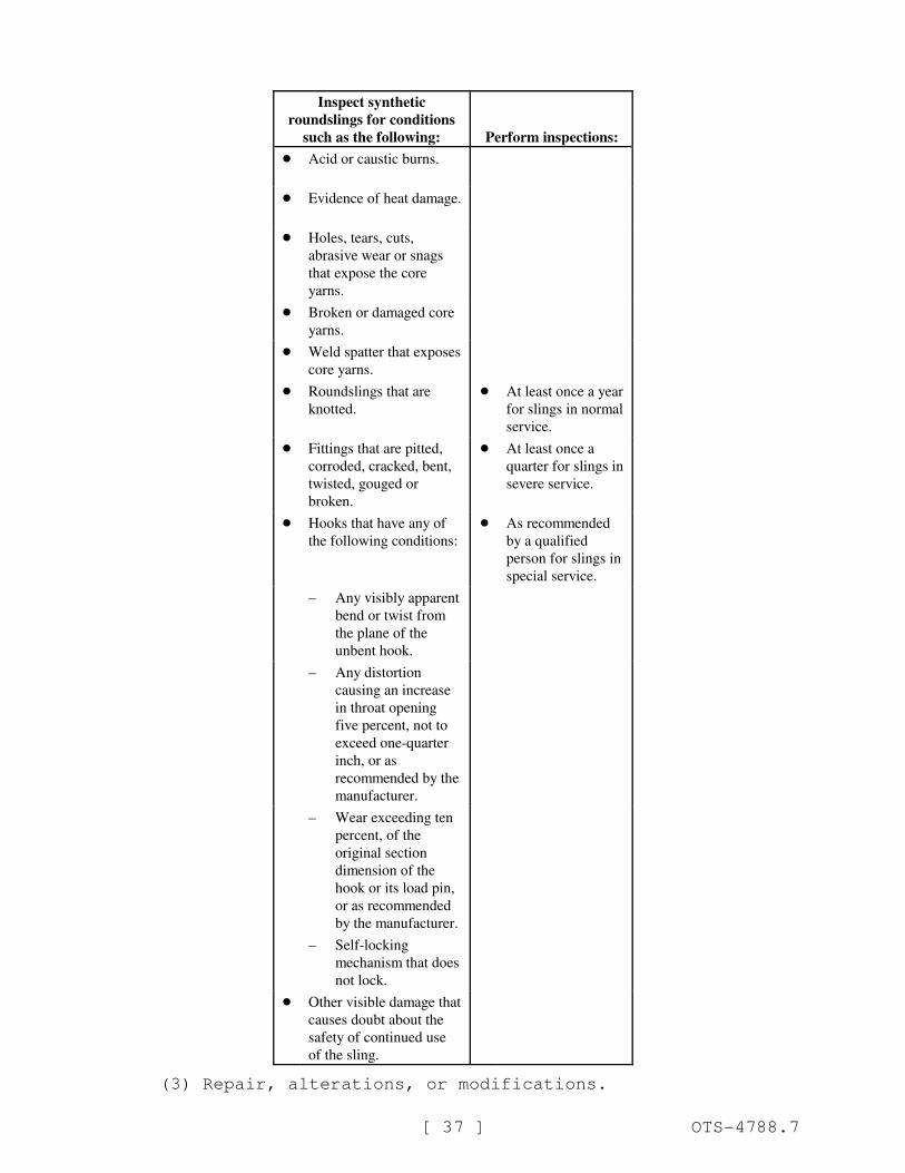
Table 17
Synthetic Roundsling Inspection and Removal Criteria
Inspect synthetic
roundslings for conditions
such as the following: Perform inspections:
! Missing or illegible sling
identification.
Inspect synthetic
roundslings for conditions
such as the following: Perform inspections:
[ 37 ] OTS-4788.7
! Acid or caustic burns.
! Evidence of heat damage.
! Holes, tears, cuts,
abrasive wear or snags
that expose the core
yarns.
! Broken or damaged core
yarns.
! Weld spatter that exposes
core yarns.
! Roundslings that are
knotted.
! At least once a year
for slings in normal
service.
! Fittings that are pitted,
corroded, cracked, bent,
twisted, gouged or
broken.
! At least once a
quarter for slings in
severe service.
! Hooks that have any of
the following conditions:
! As recommended
by a qualified
person for slings in
special service.
– Any visibly apparent
bend or twist from
the plane of the
unbent hook.
– Any distortion
causing an increase
in throat opening
five percent, not to
exceed one-quarter
inch, or as
recommended by the
manufacturer.
– Wear exceeding ten
percent, of the
original section
dimension of the
hook or its load pin,
or as recommended
by the manufacturer.
– Self-locking
mechanism that does
not lock.
! Other visible damage that
causes doubt about the
safety of continued use
of the sling.
(3) Repair, alterations, or modifications.
[ 38 ] OTS-4788.7
(a) Meet the following requirements when repairing synthetic
roundslings:
(i) Only the manufacturer or a qualified person can repair
slings;
(ii) Mark the sling to show the repairing agency;
(iii) Only use components that meet the requirements of this
rule to repair slings;
(iv) Replace cracked, broken, or bent fittings other than
hooks; do not repair them.
(b) Both of the following are prohibited:
(i) Temporary repairs of roundslings or fittings; and
(ii) The repair of load bearing yarns.
Proof load test repaired slings according to the requirements
in subsection (4) of this section.
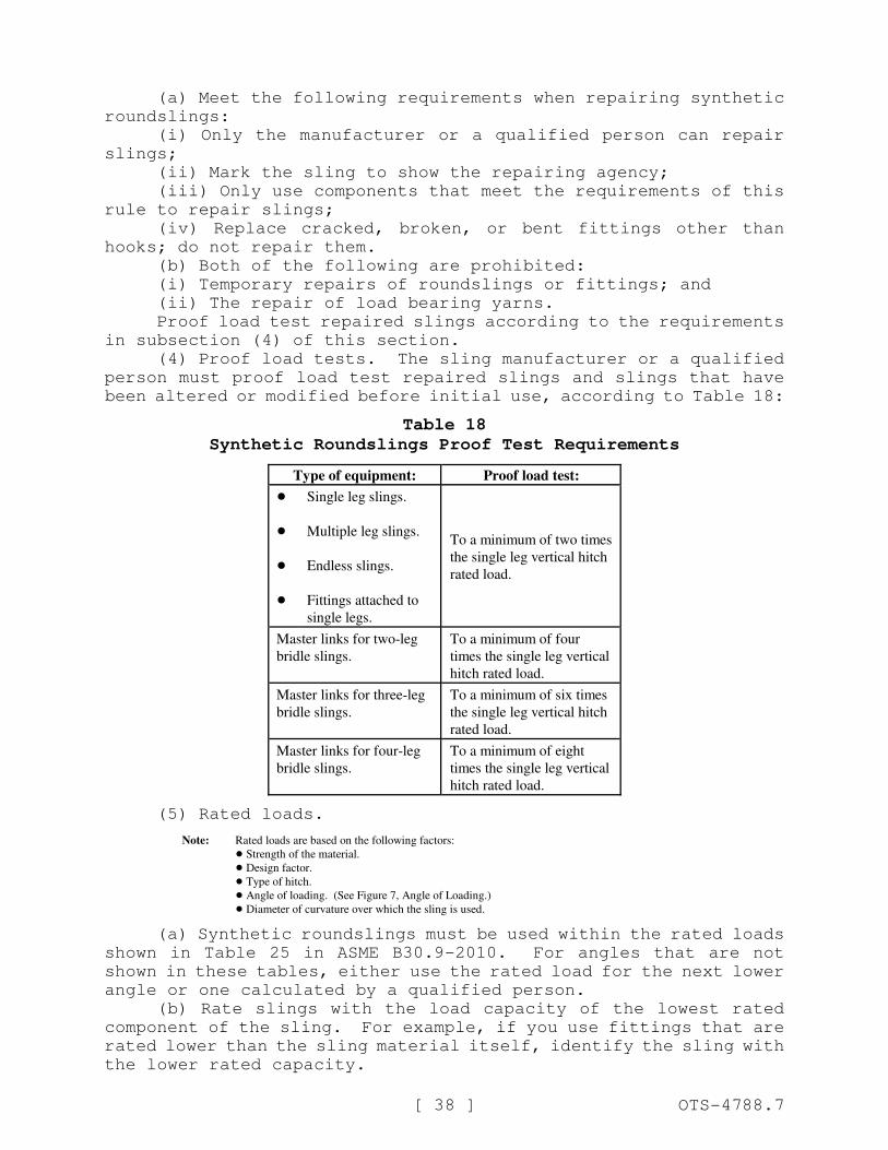
(4) Proof load tests. The sling manufacturer or a qualified
person must proof load test repaired slings and slings that have
been altered or modified before initial use, according to Table 18:
Table 18
Synthetic Roundslings Proof Test Requirements
Type of equipment: Proof load test:
!
!
!
!
Single leg slings.
Multiple leg slings.
Endless slings.
Fittings attached to
single legs.
To a minimum of two times
the single leg vertical hitch
rated load.
Master links for two-leg
bridle slings.
To a minimum of four
times the single leg vertical
hitch rated load.
Master links for three-leg
bridle slings.
To a minimum of six times
the single leg vertical hitch
rated load.
Master links for four-leg
bridle slings.
To a minimum of eight
times the single leg vertical
hitch rated load.
(5) Rated loads.
Note: Rated loads are based on the following factors:
! Strength of the material.
! Design factor.
! Type of hitch.
! Angle of loading. (See Figure 7, Angle of Loading.)
! Diameter of curvature over which the sling is used.
(a) Synthetic roundslings must be used within the rated loads
shown in Table 25 in ASME B30.9-2010. For angles that are not
shown in these tables, either use the rated load for the next lower
angle or one calculated by a qualified person.
(b) Rate slings with the load capacity of the lowest rated
component of the sling. For example, if you use fittings that are
rated lower than the sling material itself, identify the sling with
the lower rated capacity.
[ 39 ] OTS-4788.7
(c) Prohibit the use of horizontal sling angles less than
thirty degrees unless recommended by the sling manufacturer or a
qualified person.
(d) Use Figure 7, Angle of Choke, the manufacturer, or a
qualified person to determine the rated load if the angle of choke
in a choker hitch is less than one hundred twenty degrees.
(e) Rated loads for slings used in a choker hitch must conform
to the values shown in the above referenced Table 10 provided that
the angle of choke is one hundred twenty degrees or greater. (See
Figure 7.)
(6) Use of synthetic roundslings.
(a) Use methods approved by the manufacturer or qualified
person to shorten or adjust slings. Slings must not be shortened
or lengthened by knotting or twisting.
(b) Hitch slings in a way that provides control of the load.
(c) Protect slings with material of sufficient strength,
thickness, and construction to prevent damage from sharp edges,
corners, protrusions, or abrasive surfaces. (See Figure 3.)
(d) Keep all parts of the human body from between the sling
and the load, crane, or hoist hook.
(e) Intentional shock loading is prohibited.
NEW SECTION
WAC 296-155-339 Rigging hardware and lifting devices other
than slings and rigging hardware.
NEW SECTION
WAC 296-155-33900 General requirements. (1) Inspections.(a) A qualified person must perform an inspection on all
hardware according to Table 19, each day before using. If a daily
inspection is not feasible because the hardware is in a
semipermanent or inaccessible location, a periodic inspection is
allowed instead of daily.
(b) Hardware must be removed from service when it shows any
conditions listed in Table 19, or any other hazardous condition.
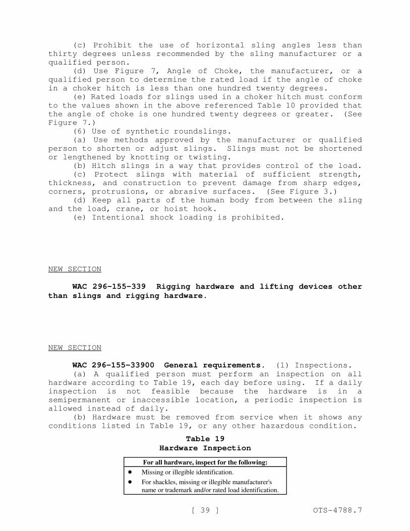
Table 19
Hardware Inspection
For all hardware, inspect for the following:
! Missing or illegible identification.
! For shackles, missing or illegible manufacturer's
name or trademark and/or rated load identification.
For all hardware, inspect for the following:
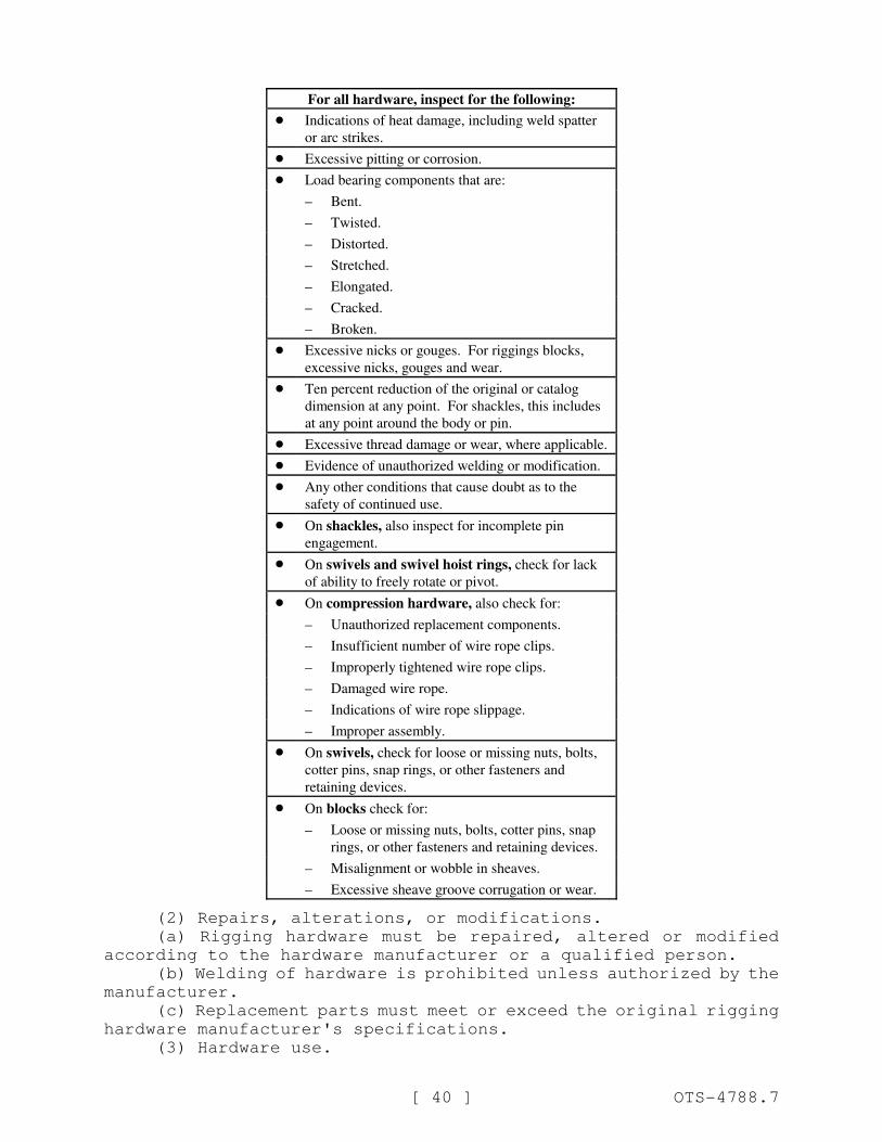
[ 40 ] OTS-4788.7
! Indications of heat damage, including weld spatter
or arc strikes.
! Excessive pitting or corrosion.
! Load bearing components that are:
– Bent.
– Twisted.
– Distorted.
– Stretched.
– Elongated.
– Cracked.
– Broken.
! Excessive nicks or gouges. For riggings blocks,
excessive nicks, gouges and wear.
! Ten percent reduction of the original or catalog
dimension at any point. For shackles, this includes
at any point around the body or pin.
! Excessive thread damage or wear, where applicable.
! Evidence of unauthorized welding or modification.
! Any other conditions that cause doubt as to the
safety of continued use.
! On shackles, also inspect for incomplete pin
engagement.
! On swivels and swivel hoist rings, check for lack
of ability to freely rotate or pivot.
! On compression hardware, also check for:
– Unauthorized replacement components.
– Insufficient number of wire rope clips.
– Improperly tightened wire rope clips.
– Damaged wire rope.
– Indications of wire rope slippage.
– Improper assembly.
! On swivels, check for loose or missing nuts, bolts,
cotter pins, snap rings, or other fasteners and
retaining devices.
! On blocks check for:
– Loose or missing nuts, bolts, cotter pins, snap
rings, or other fasteners and retaining devices.
– Misalignment or wobble in sheaves.
– Excessive sheave groove corrugation or wear.
(2) Repairs, alterations, or modifications.
(a) Rigging hardware must be repaired, altered or modified
according to the hardware manufacturer or a qualified person.
(b) Welding of hardware is prohibited unless authorized by the
manufacturer.
(c) Replacement parts must meet or exceed the original rigging
hardware manufacturer's specifications.
(3) Hardware use.
[ 41 ] OTS-4788.7
(a) Hardware must be selected with the characteristics
suitable for the application and environment where it will be used.
(b) The rated load of the hardware must not be exceeded.
(c) At least one of the workers using rigging hardware must
meet the requirements of WAC 296-155-33700.
NEW SECTION
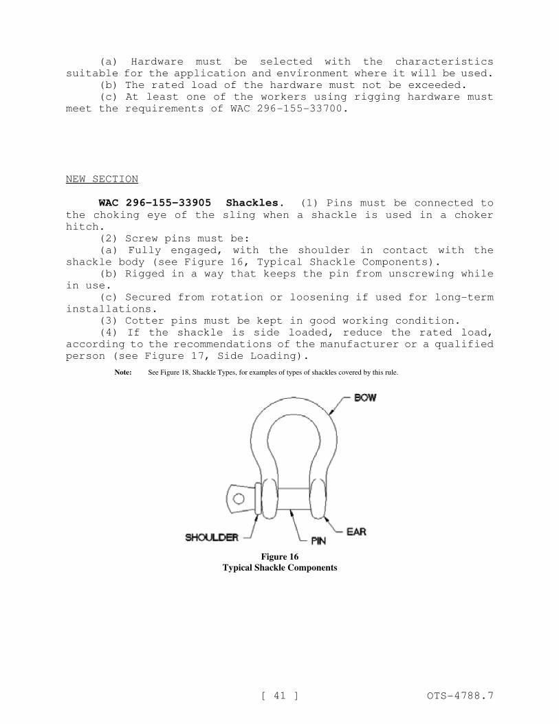
WAC 296-155-33905 Shackles. (1) Pins must be connected tothe choking eye of the sling when a shackle is used in a choker
hitch.
(2) Screw pins must be:
(a) Fully engaged, with the shoulder in contact with the
shackle body (see Figure 16, Typical Shackle Components).
(b) Rigged in a way that keeps the pin from unscrewing while
in use.
(c) Secured from rotation or loosening if used for long-term
installations.
(3) Cotter pins must be kept in good working condition.
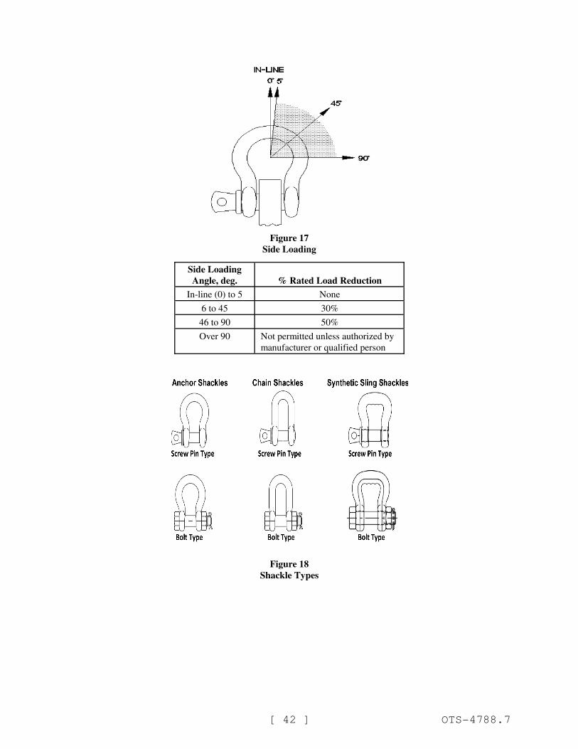
(4) If the shackle is side loaded, reduce the rated load,
according to the recommendations of the manufacturer or a qualified
person (see Figure 17, Side Loading).
Note: See Figure 18, Shackle Types, for examples of types of shackles covered by this rule.
Figure 16
Typical Shackle Components
[ 42 ] OTS-4788.7
Figure 17
Side Loading
Side Loading
Angle, deg. % Rated Load Reduction
In-line (0) to 5 None
6 to 45 30%
46 to 90 50%
Over 90 Not permitted unless authorized by
manufacturer or qualified person
Figure 18
Shackle Types
[ 43 ] OTS-4788.7
NEW SECTION
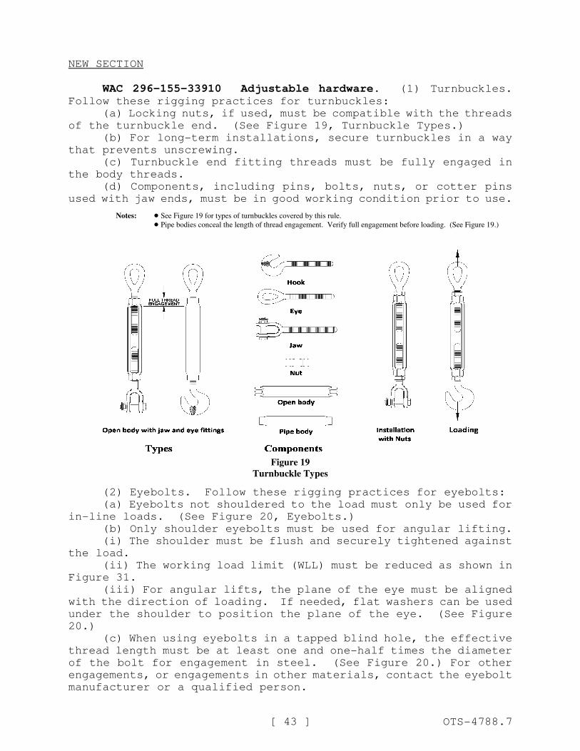
WAC 296-155-33910 Adjustable hardware. (1) Turnbuckles.Follow these rigging practices for turnbuckles:
(a) Locking nuts, if used, must be compatible with the threads
of the turnbuckle end. (See Figure 19, Turnbuckle Types.)
(b) For long-term installations, secure turnbuckles in a way
that prevents unscrewing.
(c) Turnbuckle end fitting threads must be fully engaged in
the body threads.
(d) Components, including pins, bolts, nuts, or cotter pins
used with jaw ends, must be in good working condition prior to use.
Notes: ! See Figure 19 for types of turnbuckles covered by this rule.
! Pipe bodies conceal the length of thread engagement. Verify full engagement before loading. (See Figure 19.)
Figure 19
Turnbuckle Types
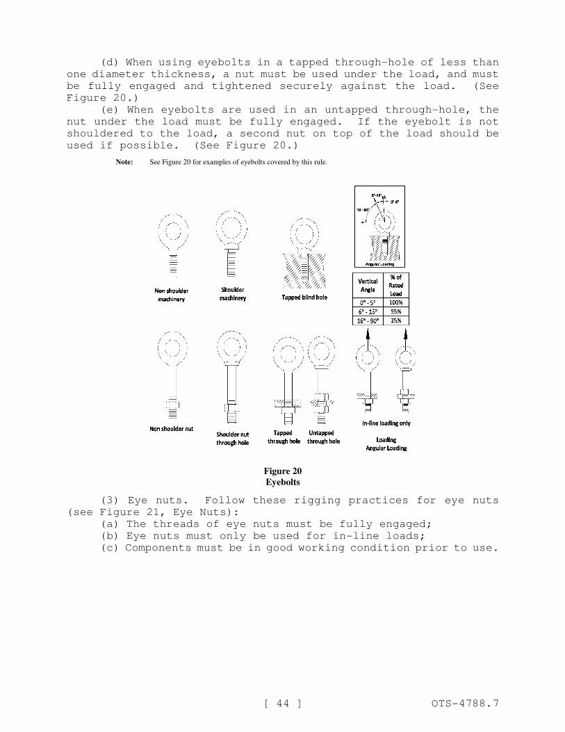
(2) Eyebolts. Follow these rigging practices for eyebolts:
(a) Eyebolts not shouldered to the load must only be used for
in-line loads. (See Figure 20, Eyebolts.)
(b) Only shoulder eyebolts must be used for angular lifting.
(i) The shoulder must be flush and securely tightened against
the load.
(ii) The working load limit (WLL) must be reduced as shown in
Figure 31.
(iii) For angular lifts, the plane of the eye must be aligned
with the direction of loading. If needed, flat washers can be used
under the shoulder to position the plane of the eye. (See Figure
20.)
(c) When using eyebolts in a tapped blind hole, the effective
thread length must be at least one and one-half times the diameter
of the bolt for engagement in steel. (See Figure 20.) For other
engagements, or engagements in other materials, contact the eyebolt
manufacturer or a qualified person.
[ 44 ] OTS-4788.7
(d) When using eyebolts in a tapped through-hole of less than
one diameter thickness, a nut must be used under the load, and must
be fully engaged and tightened securely against the load. (See
Figure 20.)
(e) When eyebolts are used in an untapped through-hole, the
nut under the load must be fully engaged. If the eyebolt is not
shouldered to the load, a second nut on top of the load should be
used if possible. (See Figure 20.)
Note: See Figure 20 for examples of eyebolts covered by this rule.
Figure 20
Eyebolts
(3) Eye nuts. Follow these rigging practices for eye nuts
(see Figure 21, Eye Nuts):
(a) The threads of eye nuts must be fully engaged;
(b) Eye nuts must only be used for in-line loads;
(c) Components must be in good working condition prior to use.
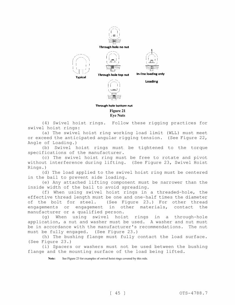
[ 45 ] OTS-4788.7
Figure 21
Eye Nuts
(4) Swivel hoist rings. Follow these rigging practices for
swivel hoist rings:
(a) The swivel hoist ring working load limit (WLL) must meet
or exceed the anticipated angular rigging tension. (See Figure 22,
Angle of Loading.)
(b) Swivel hoist rings must be tightened to the torque
specifications of the manufacturer.
(c) The swivel hoist ring must be free to rotate and pivot
without interference during lifting. (See Figure 23, Swivel Hoist
Rings.)
(d) The load applied to the swivel hoist ring must be centered
in the bail to prevent side loading.
(e) Any attached lifting component must be narrower than the
inside width of the bail to avoid spreading.
(f) When using swivel hoist rings in a threaded-hole, the
effective thread length must be one and one-half times the diameter
of the bolt for steel. (See Figure 23.) For other thread
engagements or engagement in other materials, contact the
manufacturer or a qualified person.
(g) When using swivel hoist rings in a through-hole
application, a nut and washer must be used. A washer and nut must
be in accordance with the manufacturer's recommendations. The nut
must be fully engaged. (See Figure 23.)
(h) The bushing flange must fully contact the load surface.
(See Figure 23.)
(i) Spacers or washers must not be used between the bushing
flange and the mounting surface of the load being lifted.
Note: See Figure 23 for examples of swivel hoist rings covered by this rule.
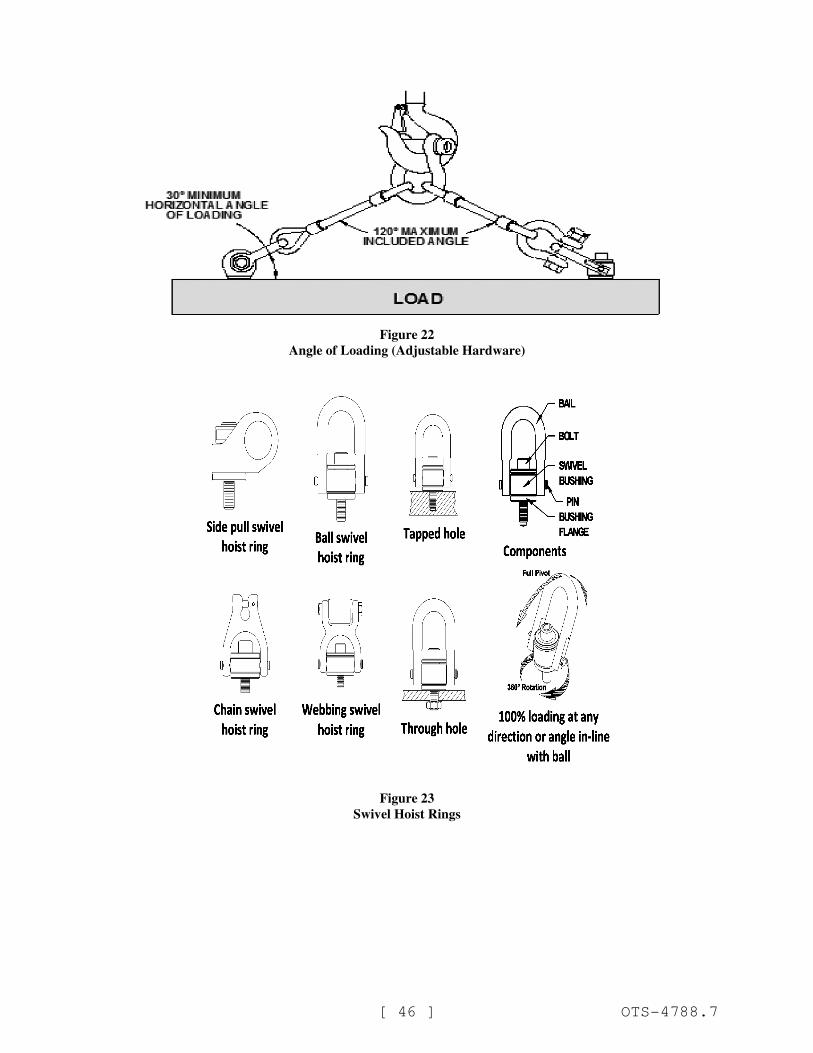
[ 46 ] OTS-4788.7
Figure 22
Angle of Loading (Adjustable Hardware)
Figure 23
Swivel Hoist Rings
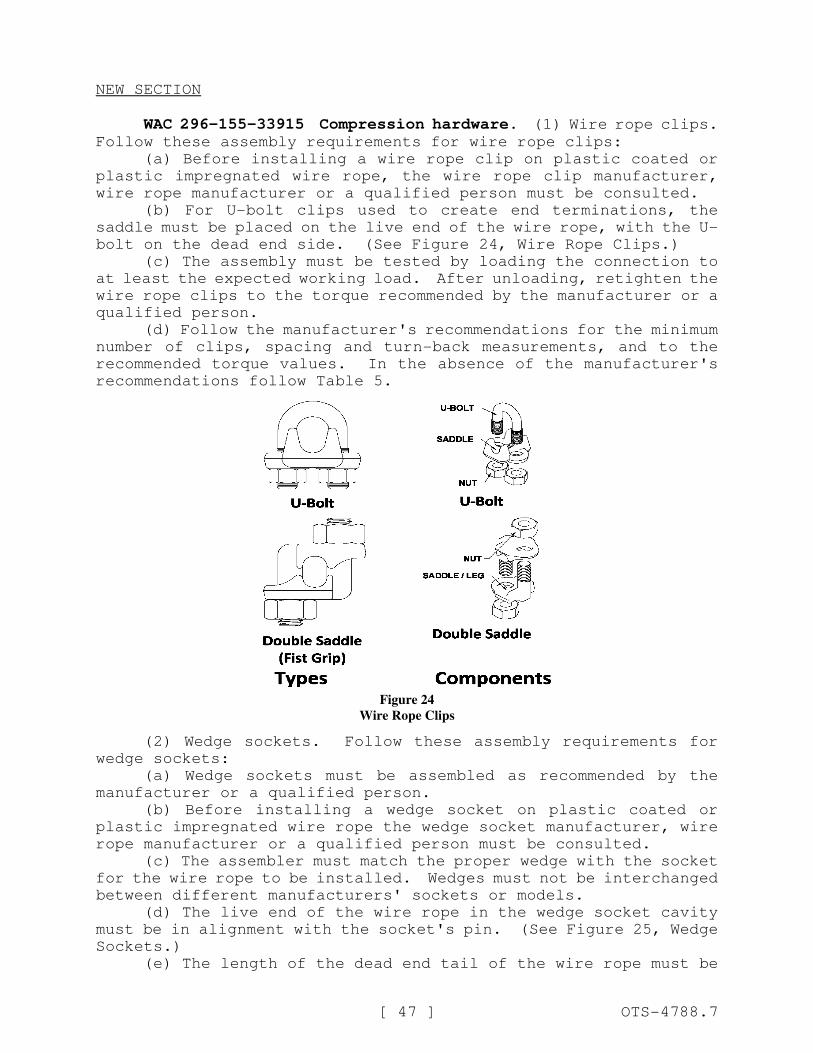
[ 47 ] OTS-4788.7
NEW SECTION
WAC 296-155-33915 Compression hardware. (1) Wire rope clips.Follow these assembly requirements for wire rope clips:
(a) Before installing a wire rope clip on plastic coated or
plastic impregnated wire rope, the wire rope clip manufacturer,
wire rope manufacturer or a qualified person must be consulted.
(b) For U-bolt clips used to create end terminations, the
saddle must be placed on the live end of the wire rope, with the U-
bolt on the dead end side. (See Figure 24, Wire Rope Clips.)
(c) The assembly must be tested by loading the connection to
at least the expected working load. After unloading, retighten the
wire rope clips to the torque recommended by the manufacturer or a
qualified person.
(d) Follow the manufacturer's recommendations for the minimum
number of clips, spacing and turn-back measurements, and to the
recommended torque values. In the absence of the manufacturer's
recommendations follow Table 5.
Figure 24
Wire Rope Clips
(2) Wedge sockets. Follow these assembly requirements for
wedge sockets:
(a) Wedge sockets must be assembled as recommended by the
manufacturer or a qualified person.
(b) Before installing a wedge socket on plastic coated or
plastic impregnated wire rope the wedge socket manufacturer, wire
rope manufacturer or a qualified person must be consulted.
(c) The assembler must match the proper wedge with the socket
for the wire rope to be installed. Wedges must not be interchanged
between different manufacturers' sockets or models.
(d) The live end of the wire rope in the wedge socket cavity
must be in alignment with the socket's pin. (See Figure 25, Wedge
Sockets.)
(e) The length of the dead end tail of the wire rope must be
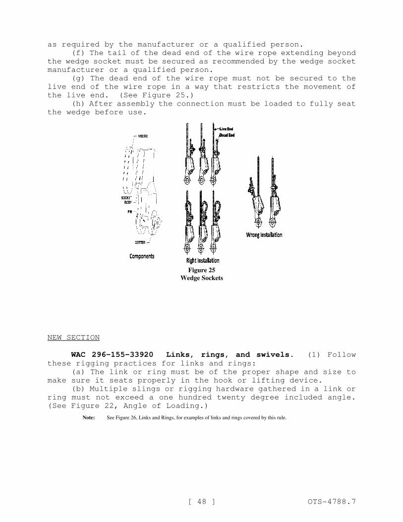
[ 48 ] OTS-4788.7
as required by the manufacturer or a qualified person.
(f) The tail of the dead end of the wire rope extending beyond
the wedge socket must be secured as recommended by the wedge socket
manufacturer or a qualified person.
(g) The dead end of the wire rope must not be secured to the
live end of the wire rope in a way that restricts the movement of
the live end. (See Figure 25.)
(h) After assembly the connection must be loaded to fully seat
the wedge before use.
Figure 25
Wedge Sockets
NEW SECTION
WAC 296-155-33920 Links, rings, and swivels. (1) Followthese rigging practices for links and rings:
(a) The link or ring must be of the proper shape and size to
make sure it seats properly in the hook or lifting device.
(b) Multiple slings or rigging hardware gathered in a link or
ring must not exceed a one hundred twenty degree included angle.
(See Figure 22, Angle of Loading.)
Note: See Figure 26, Links and Rings, for examples of links and rings covered by this rule.
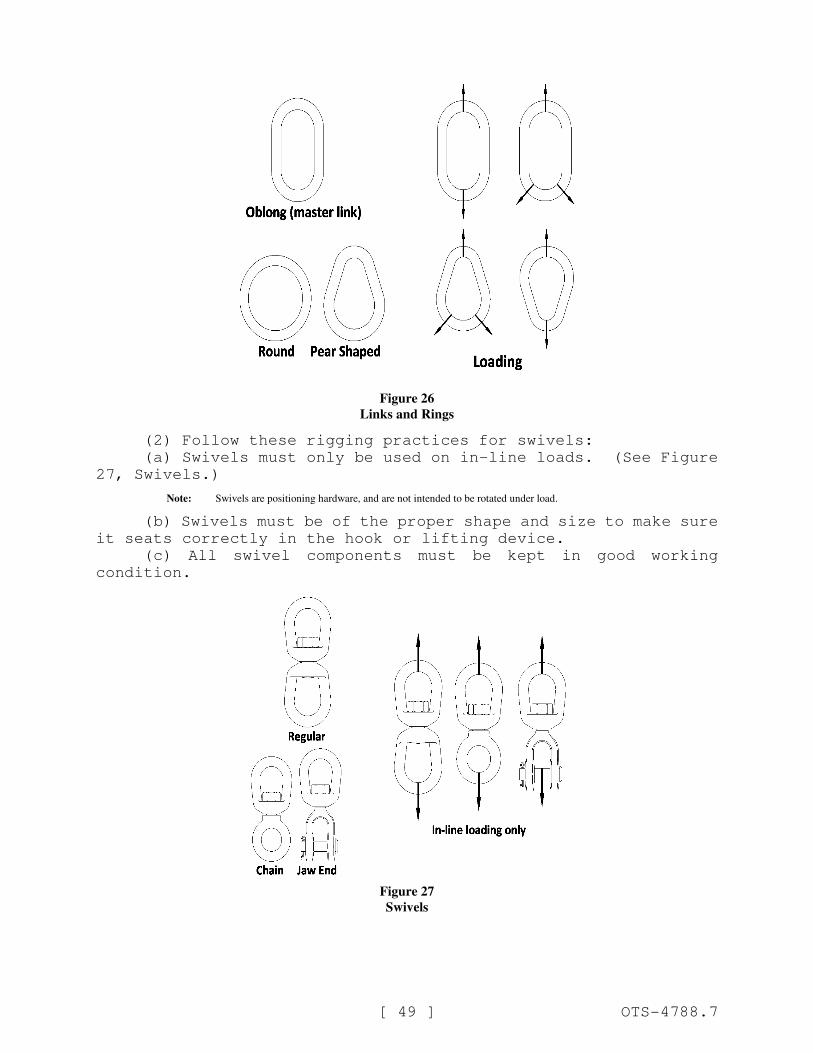
[ 49 ] OTS-4788.7
Figure 26
Links and Rings
(2) Follow these rigging practices for swivels:
(a) Swivels must only be used on in-line loads. (See Figure
27, Swivels.)
Note: Swivels are positioning hardware, and are not intended to be rotated under load.
(b) Swivels must be of the proper shape and size to make sure
it seats correctly in the hook or lifting device.
(c) All swivel components must be kept in good working
condition.
Figure 27
Swivels
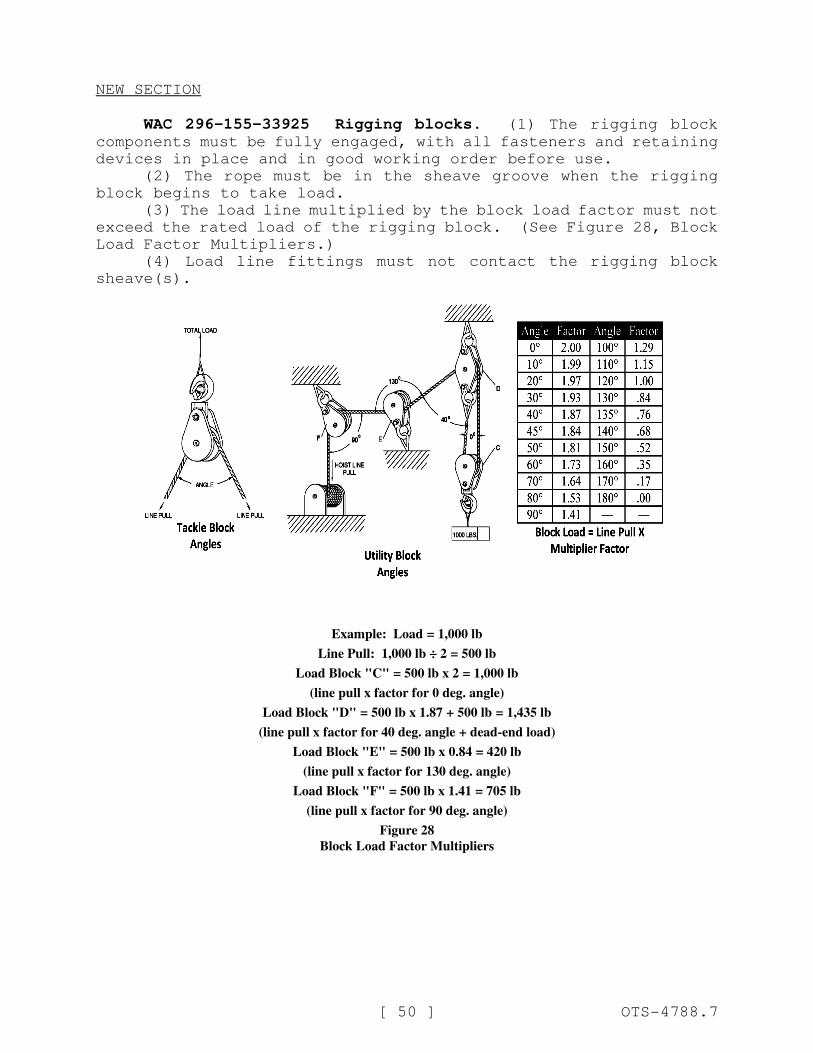
[ 50 ] OTS-4788.7
NEW SECTION
WAC 296-155-33925 Rigging blocks. (1) The rigging blockcomponents must be fully engaged, with all fasteners and retaining
devices in place and in good working order before use.
(2) The rope must be in the sheave groove when the rigging
block begins to take load.
(3) The load line multiplied by the block load factor must not
exceed the rated load of the rigging block. (See Figure 28, Block
Load Factor Multipliers.)
(4) Load line fittings must not contact the rigging block
sheave(s).
Example: Load .= 1,000 lb
Line Pull: 1,000 lb ÷ 2 .= 500 lb
Load Block "C" .= 500 lb x 2 .= 1,000 lb
(line pull x factor for 0 deg. angle)
Load Block "D" .= 500 lb x 1.87 .+ 500 lb .= 1,435 lb
(line pull x factor for 40 deg. angle .+ dead-end load)
Load Block "E" .= 500 lb x 0.84 .= 420 lb
(line pull x factor for 130 deg. angle)
Load Block "F" .= 500 lb x 1.41 .= 705 lb
(line pull x factor for 90 deg. angle)
Figure 28
Block Load Factor Multipliers
[ 51 ] OTS-4788.7
NEW SECTION
WAC 296-155-340 Lifting devices other than slings and rigging
hardware.
NEW SECTION
WAC 296-155-34005 Structural and mechanical lifters. (1)Structural and mechanical lifting devices must be constructed in
accordance with ASME B30.20-2010, Below-the-Hook Lifting Devices.
(2) The rated load of the lifting device must be legibly
marked on the main structure or on a tag attached to it where it is
visible. If the lifting device is made up of several lifters, each
detachable from the group, these lifters must also be marked with
their individual rated loads.
(3) All structural and mechanical lifting devices must be
marked with the following information:
(a) Manufacturer's name and address;
(b) Serial number;
(c) Lifter weight, if over one hundred pounds (45 kg);
(d) Rated load as required in subsection (2) of this section;
(e) Name and address of repairer or modifier, when the lifting
device has been repaired or modified.
(4) Installation.
(a) Structural and mechanical lifters must be assembled and
installed according to manufacturer's instructions.
(b) The installer must check for correct rotation of all
motors.
(5) Inspection.
(a) A qualified person must inspect all new, altered,
repaired, or modified lifting devices according to Tables 20 and
21. The inspection of altered, repaired or modified lifting
devices can be limited to the parts affected, if a qualified person
determines that is all that is needed.
(b) The operator must inspect the lifting device before and
during every lift for any indication of damage. Check the
following items:
(i) Surface of the load for debris;
(ii) Condition and operation of the controls; and
(iii) Condition and operation of the indicators and meters
when installed.
(c) Lifting devices must be inspected, by the operator or
another competent person, according to Table 20.
(i) If any damage is found, have a qualified person determine
whether there is a hazard.
(ii) Hazardous conditions must be corrected before continuing
use.
Table 20
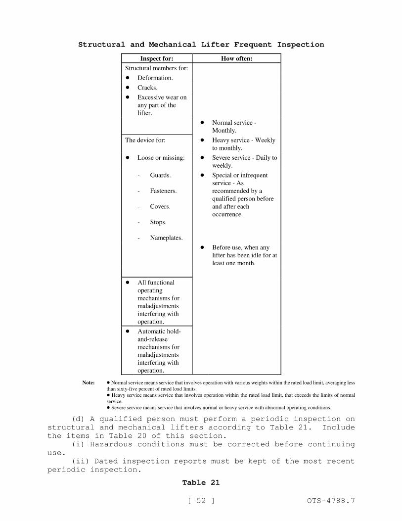
[ 52 ] OTS-4788.7
Structural and Mechanical Lifter Frequent Inspection
Inspect for: How often:
Structural members for:
! Deformation.
! Cracks.
! Excessive wear on
any part of the
lifter.
! Normal service -
Monthly.
The device for: ! Heavy service - Weekly
to monthly.
! Loose or missing: ! Severe service - Daily to
weekly.
-
-
-
-
-
Guards.
Fasteners.
Covers.
Stops.
Nameplates.
! Special or infrequent
service - As
recommended by a
qualified person before
and after each
occurrence.
! Before use, when any
lifter has been idle for at
least one month.
! All functional
operating
mechanisms for
maladjustments
interfering with
operation.
! Automatic hold-
and-release
mechanisms for
maladjustments
interfering with
operation.
Note: ! Normal service means service that involves operation with various weights within the rated load limit, averaging less
than sixty-five percent of rated load limits.
! Heavy service means service that involves operation within the rated load limit, that exceeds the limits of normal
service.
! Severe service means service that involves normal or heavy service with abnormal operating conditions.
(d) A qualified person must perform a periodic inspection on
structural and mechanical lifters according to Table 21. Include
the items in Table 20 of this section.
(i) Hazardous conditions must be corrected before continuing
use.
(ii) Dated inspection reports must be kept of the most recent
periodic inspection.
Table 21
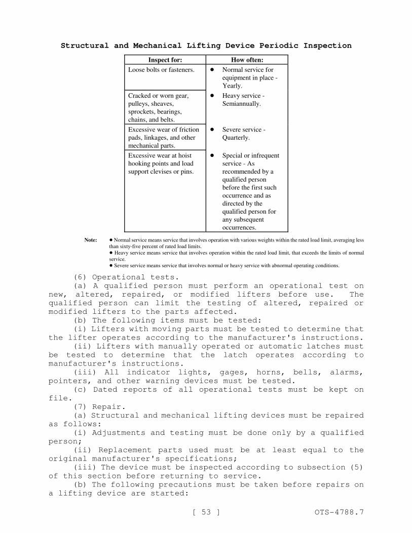
[ 53 ] OTS-4788.7
Structural and Mechanical Lifting Device Periodic Inspection
Inspect for: How often:
Loose bolts or fasteners. ! Normal service for
equipment in place -
Yearly.
Cracked or worn gear,
pulleys, sheaves,
sprockets, bearings,
chains, and belts.
! Heavy service -
Semiannually.
Excessive wear of friction
pads, linkages, and other
mechanical parts.
! Severe service -
Quarterly.
Excessive wear at hoist
hooking points and load
support clevises or pins.
! Special or infrequent
service - As
recommended by a
qualified person
before the first such
occurrence and as
directed by the
qualified person for
any subsequent
occurrences.
Note: ! Normal service means service that involves operation with various weights within the rated load limit, averaging less
than sixty-five percent of rated load limits.
! Heavy service means service that involves operation within the rated load limit, that exceeds the limits of normal
service.
! Severe service means service that involves normal or heavy service with abnormal operating conditions.
(6) Operational tests.
(a) A qualified person must perform an operational test on
new, altered, repaired, or modified lifters before use. The
qualified person can limit the testing of altered, repaired or
modified lifters to the parts affected.
(b) The following items must be tested:
(i) Lifters with moving parts must be tested to determine that
the lifter operates according to the manufacturer's instructions.
(ii) Lifters with manually operated or automatic latches must
be tested to determine that the latch operates according to
manufacturer's instructions.
(iii) All indicator lights, gages, horns, bells, alarms,
pointers, and other warning devices must be tested.
(c) Dated reports of all operational tests must be kept on
file.
(7) Repair.
(a) Structural and mechanical lifting devices must be repaired
as follows:
(i) Adjustments and testing must be done only by a qualified
person;
(ii) Replacement parts used must be at least equal to the
original manufacturer's specifications;
(iii) The device must be inspected according to subsection (5)
of this section before returning to service.
(b) The following precautions must be taken before repairs on
a lifting device are started:
[ 54 ] OTS-4788.7
(i) Disconnect, lock out and tag all sources of power "Out of
Service," if applicable;
(ii) Tag the lifting device removed from service for repair
"Out of Service."
(8) Lifting devices must be operated only by qualified
personnel.
(9) Operators must do the following:
(a) Test all controls before use, each shift;
(b) Consult a competent person before handling the load
whenever there is any doubt as to safety;
(c) Respond only to instructions from competent persons,
except for stop signals. The operator must obey a stop order at
all times, no matter who gives it;
(d) Do not load the lifting device in excess of its rated load
or with any load that it is not specifically designed for;
(e) Apply the lifter to the load according to the instruction
manual;
(f) Check that:
(i) Lifter ropes or chains are not kinked.
(ii) Multiple part lines are not twisted around each other.
(g) Bring the lifter over the load in a way that minimizes
swinging;
(h) Keep the load or lifter from contacting any obstruction;
(i) Set down any attached load and store the lifting device
before leaving it;
(j) Check that all personnel are clear of the load;
(k) Using the lifter for side pulls or sliding the load is
prohibited, unless specifically authorized by a qualified person;
(l) Riding on loads or the lifting device is prohibited.
NEW SECTION
WAC 296-155-34010 Vacuum lifters. (1) Vacuum lifting devicesmust be constructed in accordance with ASME B30.20-2010, Below-the-
Hook Lifting Devices.
(2) Rated load.
(a) The rated load of each lifter and each pad must be legibly
marked on the main structure or on a tag attached to it where it is
visible. The marking must refer to the instruction manual for
information about decreases in rating due to loads:
(i) Rigidity;
(ii) Strength;
(iii) Overhang;
(iv) Surface condition;
(v) Angle of load;
(vi) Temperature;
(vii) Number of pads;
(viii) Elevation and vacuum level.
(b) If the vacuum lifting device has shut-off valves on
[ 55 ] OTS-4788.7
individual pads or groups of pads, the rated load of each pad must
also be marked.
(3) The vacuum lifter must be clearly marked on the main
structure with all of the following:
(a) Manufacturer's name and address;
(b) Model number;
(c) Serial number;
(d) Lifter weight;
(e) Electrical power requirements, if applicable;
(f) Pressure and volume of compressed air required, if
applicable;
(g) Rated load, as required in subsection (2) of this section;
(h) If repaired or modified, the name, address, and lifter
identification of repairer or modifier.
(4) Installation.
(a) Vacuum lifters must be assembled and installed according
to manufacturer's instructions.
(b) The installer must check:
(i) That the power supply is the same as what is shown on the
nameplate.
(ii) For correct rotation of all motors.
(c) Connect the electrical power supply to the vacuum lifter
to either:
(i) The line side of the crane disconnect; or
(ii) An independent circuit.
(5) Inspection.
(a) A qualified person must inspect all new, altered,
repaired, or modified vacuum lifters. A qualified person can limit
the inspection of altered, repaired or modified lifters to the
affected parts.
(b) The operator must inspect the lifter before and during
every lift for any indication of damage, including all of the
following:
(i) Surface of the load for debris;
(ii) Seal of the vacuum pad for debris;
(iii) Condition and operation of the controls;
(iv) Condition and operation of the indicators, meters and
pumps when installed.
(c) Lifters must be inspected, by the operator or another
competent person, according to Table 22.
(d) A qualified person must determine whether signs of damage
indicate a hazard.
(e) Hazardous conditions must be corrected before continuing
use.
(f) A qualified person must perform a periodic inspection of
vacuum lifters according to Table 23. Include the items in Table
22 of this section.
(g) Dated inspection records must be kept on all critical
items such as supporting structure, motors, controls, and other
auxiliary components.
(h) Hazardous conditions must be corrected before continuing
use.
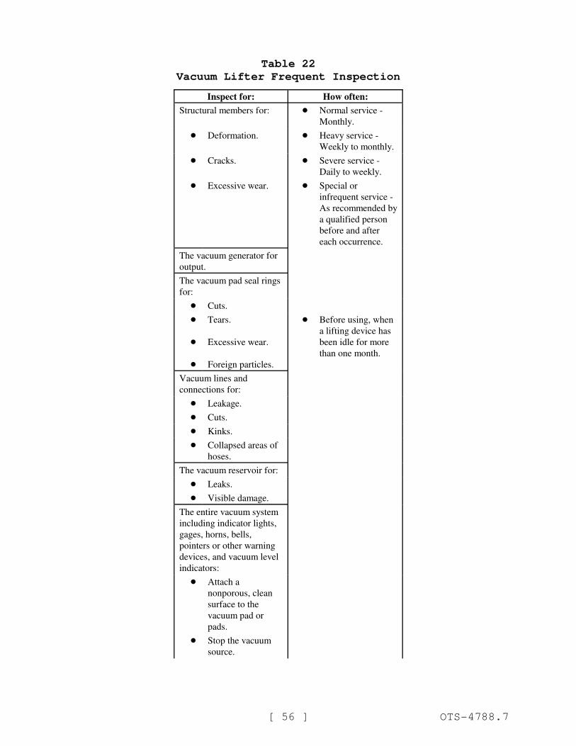
[ 56 ] OTS-4788.7
Table 22
Vacuum Lifter Frequent Inspection
Inspect for: How often:
Structural members for: ! Normal service -
Monthly.
! Deformation. ! Heavy service -
Weekly to monthly.
! Cracks. ! Severe service -
Daily to weekly.
! Excessive wear. ! Special or
infrequent service -
As recommended by
a qualified person
before and after
each occurrence.
The vacuum generator for
output.
The vacuum pad seal rings
for:
! Cuts.
!
!
!
Tears.
Excessive wear.
Foreign particles.
! Before using, when
a lifting device has
been idle for more
than one month.
Vacuum lines and
connections for:
! Leakage.
! Cuts.
! Kinks.
! Collapsed areas of
hoses.
The vacuum reservoir for:
! Leaks.
! Visible damage.
The entire vacuum system
including indicator lights,
gages, horns, bells,
pointers or other warning
devices, and vacuum level
indicators:
! Attach a
nonporous, clean
surface to the
vacuum pad or
pads.
! Stop the vacuum
source.
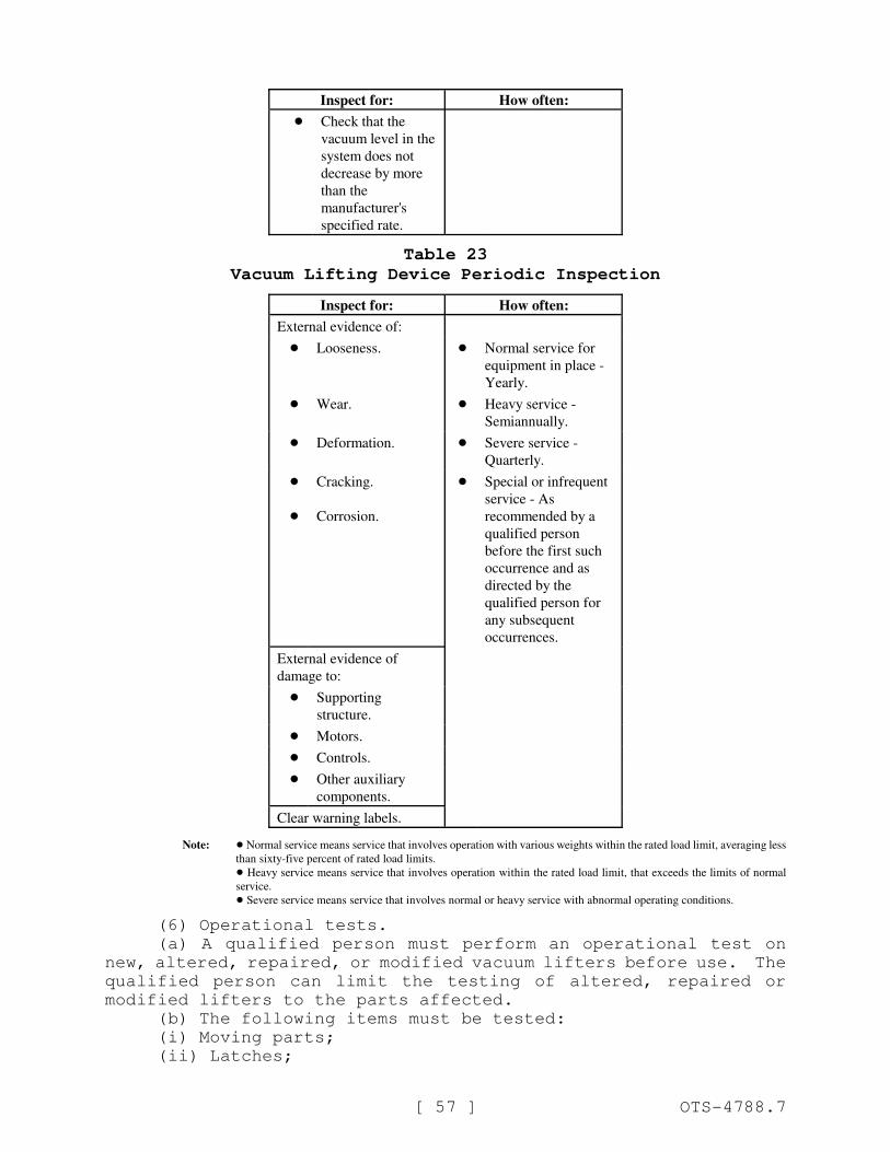
Inspect for: How often:
[ 57 ] OTS-4788.7
! Check that the
vacuum level in the
system does not
decrease by more
than the
manufacturer's
specified rate.
Table 23
Vacuum Lifting Device Periodic Inspection
Inspect for: How often:
External evidence of:
! Looseness. ! Normal service for
equipment in place -
Yearly.
! Wear. ! Heavy service -
Semiannually.
! Deformation. ! Severe service -
Quarterly.
!
!
Cracking.
Corrosion.
! Special or infrequent
service - As
recommended by a
qualified person
before the first such
occurrence and as
directed by the
qualified person for
any subsequent
occurrences.
External evidence of
damage to:
! Supporting
structure.
! Motors.
! Controls.
! Other auxiliary
components.
Clear warning labels.
Note: ! Normal service means service that involves operation with various weights within the rated load limit, averaging less
than sixty-five percent of rated load limits.
! Heavy service means service that involves operation within the rated load limit, that exceeds the limits of normal
service.
! Severe service means service that involves normal or heavy service with abnormal operating conditions.
(6) Operational tests.
(a) A qualified person must perform an operational test on
new, altered, repaired, or modified vacuum lifters before use. The
qualified person can limit the testing of altered, repaired or
modified lifters to the parts affected.
(b) The following items must be tested:
(i) Moving parts;
(ii) Latches;
[ 58 ] OTS-4788.7
(iii) Stops;
(iv) Limit switches;
(v) Control devices;
(vi) Vacuum lines;
(vii) The seals and connections must be tested for leaks by
attaching a smooth nonporous clean material to the vacuum pad or
pads and then stopping the vacuum source. The vacuum level in the
system must not decrease more than the manufacturer's specified
rate.
(c) Dated reports of all operations tests must be kept on
file.
(7) Load tests.
(a) Prior to initial use, all new, altered, repaired, or
modified vacuum lifting devices must be load tested and inspected
by a qualified person. The qualified person can limit the test to
the areas affected by the alteration, repair or modification.
(b) Test loads must not be more than one hundred twenty-five
percent of the rated load of the system, unless otherwise
recommended by the manufacturer or a qualified person.
(c) Written reports must be kept confirming the load rating of
the vacuum lifting device.
(d) The load test must consist of one of the following
procedures:
(i) Actual load test:
(A) Attach pads to the designated test load.
(B) Raise the test load a small distance to make sure the load
is supported by the vacuum-lifting device.
(C) Hold the load for two minutes.
(D) Lower the load for release.
(ii) Simulated load test. Using a test fixture, apply forces
to all load bearing components either individually or in assemblies
equivalent to the forces encountered by the components if they were
supporting a load that was one hundred twenty-five percent of the
rated load.
(e) After the test, the vacuum lifting device must be visually
inspected. Any condition that constitutes a hazard must be
corrected before the lifting device is placed in service. If the
correction affects the structure, then the lifter must be retested.
(8) Repair.
(a) Repair vacuum lifting devices as follows:
(i) Adjustments and testing must be done only by a qualified
person;
(ii) Use replacement parts that are at least equal to the
original manufacturer's specification;
(iii) The lifting device must be inspected before returning to
service as required in subsection (5) of this section.
(b) Take the following precautions before repairs on a lifting
device are started:
(i) Move the vacuum-lifting device to an area where it will
cause the least interference with other operations;
(ii) Disconnect, lock out and tag all sources of power "Out of
Service," if applicable;
(iii) Tag the lifting device removed from service for repair
[ 59 ] OTS-4788.7
"Out of Service."
(9) Lifting devices must be operated only by qualified
personnel.
(10) Operators must do the following:
(a) Test all controls before use during a shift;
(b) Consult a competent person before handling the load
whenever safety is in doubt;
(c) Respond only to instructions from competent persons,
except for stop orders. The operator must obey a stop order at all
times, no matter who gives it;
(d) Do not load the lifter in excess of its rated load or with
any load that it isn't specifically designed for;
(e) Apply the lifter to the load according to the
manufacturer's instructions;
(f) Check that:
(i) Ropes or chains are not kinked.
(ii) Multiple part lines are not twisted around each other.
(iii) The pad contact surface is clean and free of loose
particles.
(g) Check that vacuum lines are not:
(i) Kinked or twisted.
(ii) Wrapped around or looped over parts of the lifting device
that will move during the lift.
(h) Bring the lifter over the load in a way that minimizes
swinging;
(i) Lift the load a few inches to make sure that the lifting
device was correctly applied;
(j) Keep the load or lifter from contacting any obstruction;
(k) Do the following if power goes off while making a lift:
(i) Warn all people in the area;
(ii) Set the load down if possible.
(l) Set down any attached load and store the lifting device
before leaving it;
(m) Check that all personnel are clear of the load;
(n) Using the lifter for side pulls or sliding the load is
prohibited, unless specifically authorized by a qualified person;
(o) Riding on the load or the lifter is prohibited.
NEW SECTION
WAC 296-155-34015 Close proximity lifting magnets. (1) Closeproximity lifting magnets must be constructed in accordance with
ASME B30.20-2010, Below-the-Hook Lifting Devices.
(2) Rated load.
(a) General application magnets must have the rated load
(capacity) marked either on the lifting magnet or on a tag attached
to it. The marking must refer to the instruction manual for
information about decreases in rating due to the loads.
(i) Surface condition.

[ 60 ] OTS-4788.7
(ii) Thickness.
(iii) Percentage of contact with the magnet.
(iv) Temperature.
(v) Metallurgical composition.
(vi) Deflection.
(b) Specified application magnets must have the rated load
(capacity) either on the lifting magnet or on a tag attached to it,
referring to the specific loads for which the capacity applies.
(3) Identification. All close proximity lifting magnets must
be marked with the following information:
(a) Manufacturer's name and address;
(b) Model and lifting magnet unit identification;
(c) Weight of lifting magnet;
(d) Rated load, as required in subsection (2) of this section;
(e) Duty cycle, if applicable;
(f) Cold current (amps) at sixty-eight degrees Fahrenheit
(twenty degrees Celsius), if applicable; and
(g) Voltage of primary power supply or battery, if applicable.
(h) If repaired or modified, name and address of repairer or
modifier and (a) through (g) of this subsection if changed.
(4) Lifting magnets must be installed according to
manufacturer's instructions.
(5) Inspection.
(a) A qualified person must inspect all new, altered,
repaired, or modified lifting magnets according to Tables 24 and
25. The inspection of altered, repaired or modified lifting
magnets can be limited to the parts affected, if a qualified person
determines that is all that is needed.
(b) The operator must inspect the lifting magnet before and
during every lift for any indication of damage. Check all of the
following items:
(i) Lifting magnet face and surface of the load for foreign
materials and smoothness;
(ii) Condition and operation of the:
(A) Control handle of a manually controlled permanent magnet;
(B) Indicators and meters when installed.
(c) Lifting magnets must be inspected, by the operator or
another competent person, according to Table 24.
(d) A qualified person must determine whether signs of damage
indicate a hazard.
(e) Hazardous conditions must be corrected before continuing
use.
Table 24
Close Proximity Lifting Magnet Frequent Inspection
Inspect for: How often:
Structural and suspension
members for:
! Deformation. ! Normal service -
Monthly.
! Cracks. ! Heavy service -
Weekly to monthly.
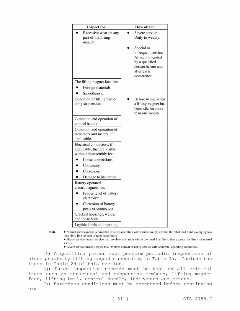
Inspect for: How often:
[ 61 ] OTS-4788.7
! Excessive wear on any
part of the lifting
magnet.
! Severe service -
Daily to weekly.
! Special or
infrequent service -
As recommended
by a qualified
person before and
after each
occurrence.
The lifting magnet face for:
! Foreign materials.
! Smoothness.
Condition of lifting bail or
sling suspension.
! Before using, when
a lifting magnet has
been idle for more
than one month.
Condition and operation of
control handle.
Condition and operation of
indicators and meters, if
applicable.
Electrical conductors, if
applicable, that are visible
without disassembly for:
! Loose connections.
! Continuity.
! Corrosion.
! Damage to insulation.
Battery operated
electromagnets for:
! Proper level of battery
electrolyte.
! Corrosion of battery
posts or connectors.
Cracked housings, welds,
and loose bolts.
Legible labels and marking.
Note: ! Normal service means service that involves operation with various weights within the rated load limit, averaging less
than sixty-five percent of rated load limits.
! Heavy service means service that involves operation within the rated load limit, that exceeds the limits of normal
service.
! Severe service means service that involves normal or heavy service with abnormal operating conditions.
(f) A qualified person must perform periodic inspections of
close proximity lifting magnets according to Table 25. Include the
items in Table 24 of this section.
(g) Dated inspection records must be kept on all critical
items such as structural and suspension members, lifting magnet
face, lifting bail, control handle, indicators and meters.
(h) Hazardous conditions must be corrected before continuing
use.
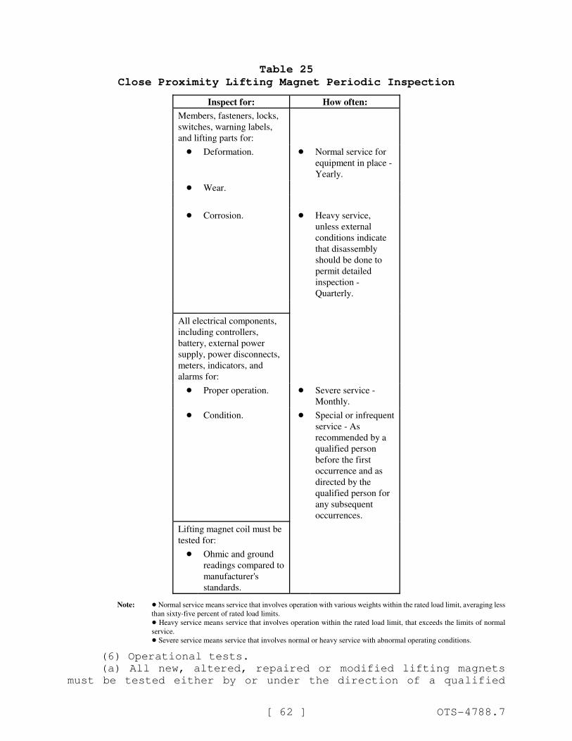
[ 62 ] OTS-4788.7
Table 25
Close Proximity Lifting Magnet Periodic Inspection
Inspect for: How often:
Members, fasteners, locks,
switches, warning labels,
and lifting parts for:
! Deformation. ! Normal service for
equipment in place -
Yearly.
! Wear.
! Corrosion. ! Heavy service,
unless external
conditions indicate
that disassembly
should be done to
permit detailed
inspection -
Quarterly.
All electrical components,
including controllers,
battery, external power
supply, power disconnects,
meters, indicators, and
alarms for:
! Proper operation. ! Severe service -
Monthly.
! Condition. ! Special or infrequent
service - As
recommended by a
qualified person
before the first
occurrence and as
directed by the
qualified person for
any subsequent
occurrences.
Lifting magnet coil must be
tested for:
! Ohmic and ground
readings compared to
manufacturer's
standards.
Note: ! Normal service means service that involves operation with various weights within the rated load limit, averaging less
than sixty-five percent of rated load limits.
! Heavy service means service that involves operation within the rated load limit, that exceeds the limits of normal
service.
! Severe service means service that involves normal or heavy service with abnormal operating conditions.
(6) Operational tests.
(a) All new, altered, repaired or modified lifting magnets
must be tested either by or under the direction of a qualified
[ 63 ] OTS-4788.7
person before use. The qualified person can limit the testing of
altered, repaired or modified lifting magnets to the parts
affected.
(b) The following items must be tested:
(i) Moving parts;
(ii) Latches;
(iii) Stops;
(iv) Switches;
(v) Control devices;
(vi) Alarms; and
(vii) Warning devices, including:
(A) Indicator lights;
(B) Gauges;
(C) Horns;
(D) Bells; and
(E) Pointers.
(c) Dated reports of all operational tests must be kept on
file.
(7) Load tests.
(a) Prior to initial use, all new, altered, repaired, or
modified close proximity lifting devices must be load tested and
inspected by a qualified person. The qualified person can limit
the test to the areas affected by the alteration, repair, or
modification.
(b) The breakaway force of lifting magnets must be tested
according to manufacturer's directions or ANSI B30.20-2010.
(8) Repair.
(a) Close proximity lifting magnets must be repaired as
follows:
(i) Adjustments and testing must be done by or under the
direction of a qualified person;
(ii) Replacement parts used must be at least equal to the
original manufacturer's specifications;
(iii) The magnet must be inspected before returning to service
as required in subsection (5) of this section.
(b) The following precautions must be taken before repairs on
a magnet are started:
(i) Disconnect, lock out and tag all sources of power "Out of
Service," if applicable; and
(ii) Tag any lifting magnet removed from service for repair
"Out of Service."
(9) Lifting magnets must be operated only by qualified
personnel.
(10) Operators must do the following:
(a) Test all controls before use, each shift;
(b) Check all meters and indicators for proper operation
before making a lift;
(c) Consult a competent person before handling the load
whenever there is any doubt as to safety;
(d) Respond only to instructions from competent persons,
except for stop orders. Operators must obey a stop order at all
times, no matter who gives it;
(e) Do not load the lifting magnet in excess of its rated load
[ 64 ] OTS-4788.7
or with any load that it isn't specifically designed for;
(f) Apply the magnet to the load according to the instruction
manual;
(g) Check that:
(i) Lifter ropes or chains are not kinked;
(ii) Multiple part lines are not twisted around each other;
(iii) The lifting magnet face and the contact area on the load
are clean.
(h) Bring the magnet over the load in a way that minimizes
swinging;
(i) Lift the load a few inches to make sure that the lifting
magnet has been correctly applied;
(j) Keep the load or lifting magnet from contact with any
obstruction;
(k) Set down any attached load and store the lifting magnet
before leaving it;
(l) Check that all people near the lift are warned before
lifting;
(m) Using the lifter for side pulls or sliding the load is
prohibited, unless specifically authorized by a qualified person;
and
(n) Riding on loads or the lifting magnet is prohibited.
NEW SECTION
WAC 296-155-34020 Remotely operated lifting magnets. (1)Remotely operated lifting magnets must be constructed in accordance
with ASME B30.20-2010, Below-the-Hook Lifting Devices.
(2) Identification. All remotely operated lifting magnets
must be marked with the following information:
(a) Manufacturer's name and address;
(b) Model or unit identification;
(c) Weight of lifting magnet;
(d) Duty cycle;
(e) Cold current;
(f) Voltage;
(g) If repaired or modified, name and address of repairer or
modifier and (a) through (g) of this subsection if changed.
(3) Lifting magnets must be installed according to
manufacturer's instructions.
(4) Inspections.
(a) A qualified person must inspect all new, altered, repaired
or modified lifting magnets according to Tables 26 and 27. A
qualified person can limit the inspection of altered, repaired or
modified lifting magnets to the parts affected.
(b) Lifting magnets must be inspected, by the operator or
another competent person, according to Table 26.
(c) A qualified person must determine whether signs of damage
indicate a hazard.
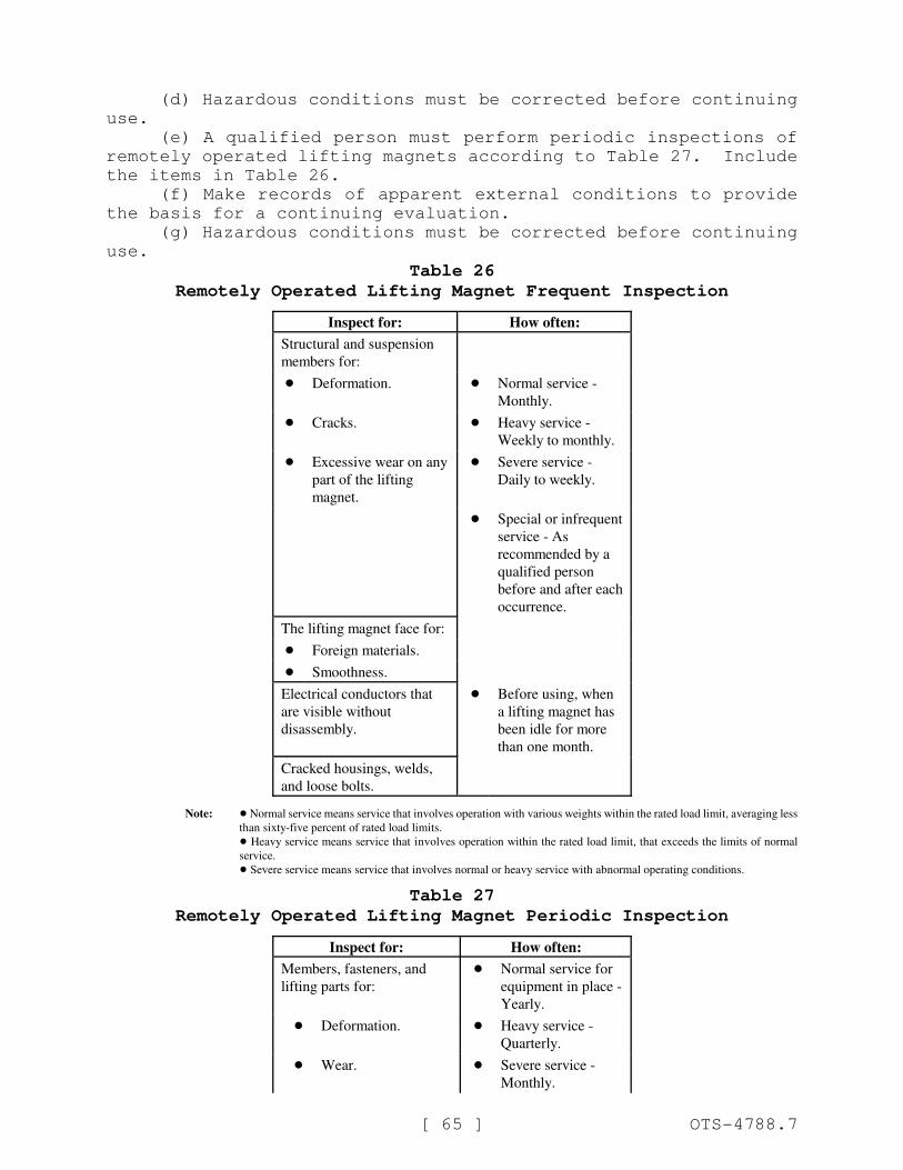
[ 65 ] OTS-4788.7
(d) Hazardous conditions must be corrected before continuing
use.
(e) A qualified person must perform periodic inspections of
remotely operated lifting magnets according to Table 27. Include
the items in Table 26.
(f) Make records of apparent external conditions to provide
the basis for a continuing evaluation.
(g) Hazardous conditions must be corrected before continuing
use.
Table 26
Remotely Operated Lifting Magnet Frequent Inspection
Inspect for: How often:
Structural and suspension
members for:
! Deformation. ! Normal service -
Monthly.
! Cracks. ! Heavy service -
Weekly to monthly.
! Excessive wear on any
part of the lifting
magnet.
! Severe service -
Daily to weekly.
! Special or infrequent
service - As
recommended by a
qualified person
before and after each
occurrence.
The lifting magnet face for:
! Foreign materials.
! Smoothness.
Electrical conductors that
are visible without
disassembly.
! Before using, when
a lifting magnet has
been idle for more
than one month.
Cracked housings, welds,
and loose bolts.
Note: ! Normal service means service that involves operation with various weights within the rated load limit, averaging less
than sixty-five percent of rated load limits.
! Heavy service means service that involves operation within the rated load limit, that exceeds the limits of normal
service.
! Severe service means service that involves normal or heavy service with abnormal operating conditions.
Table 27
Remotely Operated Lifting Magnet Periodic Inspection
Inspect for: How often:
Members, fasteners, and
lifting parts for:
! Normal service for
equipment in place -
Yearly.
! Deformation. ! Heavy service -
Quarterly.
! Wear. ! Severe service -
Monthly.
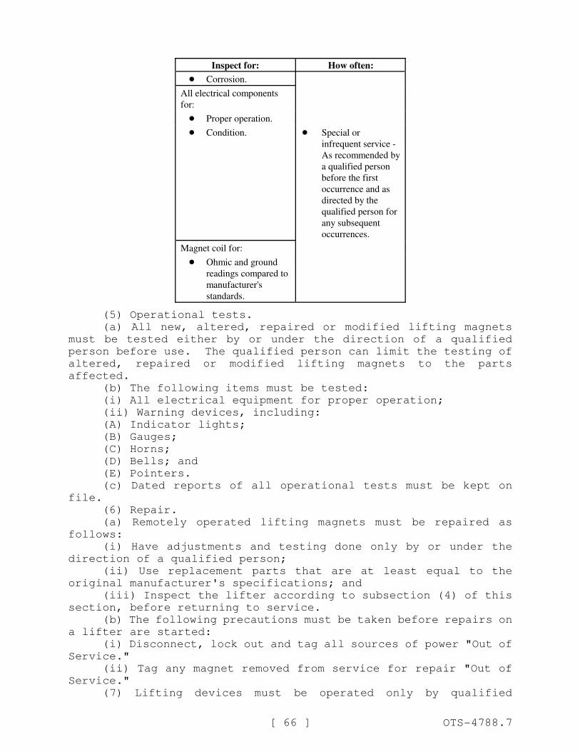
Inspect for: How often:
[ 66 ] OTS-4788.7
! Corrosion.
All electrical components
for:
! Proper operation.
! Condition. ! Special or
infrequent service -
As recommended by
a qualified person
before the first
occurrence and as
directed by the
qualified person for
any subsequent
occurrences.
Magnet coil for:
! Ohmic and ground
readings compared to
manufacturer's
standards.
(5) Operational tests.
(a) All new, altered, repaired or modified lifting magnets
must be tested either by or under the direction of a qualified
person before use. The qualified person can limit the testing of
altered, repaired or modified lifting magnets to the parts
affected.
(b) The following items must be tested:
(i) All electrical equipment for proper operation;
(ii) Warning devices, including:
(A) Indicator lights;
(B) Gauges;
(C) Horns;
(D) Bells; and
(E) Pointers.
(c) Dated reports of all operational tests must be kept on
file.
(6) Repair.
(a) Remotely operated lifting magnets must be repaired as
follows:
(i) Have adjustments and testing done only by or under the
direction of a qualified person;
(ii) Use replacement parts that are at least equal to the
original manufacturer's specifications; and
(iii) Inspect the lifter according to subsection (4) of this
section, before returning to service.
(b) The following precautions must be taken before repairs on
a lifter are started:
(i) Disconnect, lock out and tag all sources of power "Out of
Service."
(ii) Tag any magnet removed from service for repair "Out of
Service."
(7) Lifting devices must be operated only by qualified
[ 67 ] OTS-4788.7
personnel.
(8) Operators must do the following:
(a) Test all controls before use during a shift;
(b) Consult a competent person before handling the load
whenever there is any doubt as to safety;
(c) Respond only to instructions from competent persons,
except for stop orders. Operators must obey a stop order at all
times, no matter who gives it;
(d) Do not load the lifting magnet in excess of its rated load
or with any load that it is not specifically designed for;
(e) Apply the lifting magnet to the load according to the
instruction manual;
(f) Check that:
(i) Lifter ropes or chains are not kinked;
(ii) Multiple part lines are not twisted around each other.
(g) Bring the lifting magnet over the load in a way that
minimizes swinging;
(h) Keep the load or magnet from contact with any obstruction;
(i) Set down any attached load and store the lifting magnet
before leaving it;
(j) Check that all people are clear of the load;
(k) Using the lifter for side pulls or sliding the load is
prohibited, unless specifically authorized by a qualified person;
and
(l) Riding on loads or the lifting magnet is prohibited.
NEW SECTION
WAC 296-155-34025 Scrap and material handling grapples. (1)Grapples must be constructed in accordance with ASME B30.20-2010,
Below-the-Hook Lifting Devices.
(2) Identification. All grapples must be marked with the
following information:
(a) Manufacturer's name and address;
(b) Serial number or unit identification;
(c) Grapple weight;
(d) Rated voltage, if applicable;
(e) Operating hydraulic pressure(s), if applicable;
(f) Rated capacity;
(g) If repaired or modified, name and address of repairer or
modifier and (a) through (f) of this subsection if changed.
(3) Grapple installation.
(a) Grapples must be installed according to manufacturer's
instructions.
(b) The hydraulic flows and pressures must be the same as
shown in the manufacturer's instructions.
(4) Inspections.
(a) A qualified person must inspect all new, altered, repaired
and modified grapples according to Table 28. A qualified person
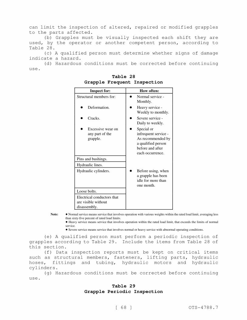
[ 68 ] OTS-4788.7
can limit the inspection of altered, repaired or modified grapples
to the parts affected.
(b) Grapples must be visually inspected each shift they are
used, by the operator or another competent person, according to
Table 28.
(c) A qualified person must determine whether signs of damage
indicate a hazard.
(d) Hazardous conditions must be corrected before continuing
use.
Table 28
Grapple Frequent Inspection
Inspect for: How often:
Structural members for: ! Normal service -
Monthly.
! Deformation. ! Heavy service -
Weekly to monthly.
! Cracks. ! Severe service -
Daily to weekly.
! Excessive wear on
any part of the
grapple.
! Special or
infrequent service -
As recommended by
a qualified person
before and after
each occurrence.
Pins and bushings.
Hydraulic lines.
Hydraulic cylinders. ! Before using, when
a grapple has been
idle for more than
one month.
Loose bolts.
Electrical conductors that
are visible without
disassembly.
Note: ! Normal service means service that involves operation with various weights within the rated load limit, averaging less
than sixty-five percent of rated load limits.
! Heavy service means service that involves operation within the rated load limit, that exceeds the limits of normal
service.
! Severe service means service that involves normal or heavy service with abnormal operating conditions.
(e) A qualified person must perform a periodic inspection of
grapples according to Table 29. Include the items from Table 28 of
this section.
(f) Data inspection reports must be kept on critical items
such as structural members, fasteners, lifting parts, hydraulic
hoses, fittings and tubing, hydraulic motors and hydraulic
cylinders.
(g) Hazardous conditions must be corrected before continuing
use.
Table 29
Grapple Periodic Inspection
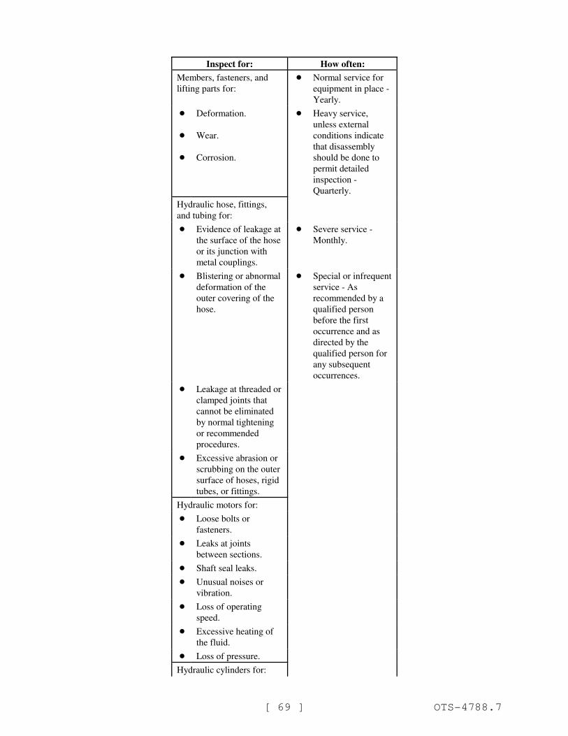
[ 69 ] OTS-4788.7
Inspect for: How often:
Members, fasteners, and
lifting parts for:
! Normal service for
equipment in place -
Yearly.
!
!
!
Deformation.
Wear.
Corrosion.
! Heavy service,
unless external
conditions indicate
that disassembly
should be done to
permit detailed
inspection -
Quarterly.
Hydraulic hose, fittings,
and tubing for:
! Evidence of leakage at
the surface of the hose
or its junction with
metal couplings.
! Severe service -
Monthly.
! Blistering or abnormal
deformation of the
outer covering of the
hose.
! Special or infrequent
service - As
recommended by a
qualified person
before the first
occurrence and as
directed by the
qualified person for
any subsequent
occurrences.
! Leakage at threaded or
clamped joints that
cannot be eliminated
by normal tightening
or recommended
procedures.
! Excessive abrasion or
scrubbing on the outer
surface of hoses, rigid
tubes, or fittings.
Hydraulic motors for:
! Loose bolts or
fasteners.
! Leaks at joints
between sections.
! Shaft seal leaks.
! Unusual noises or
vibration.
! Loss of operating
speed.
! Excessive heating of
the fluid.
! Loss of pressure.
Hydraulic cylinders for:
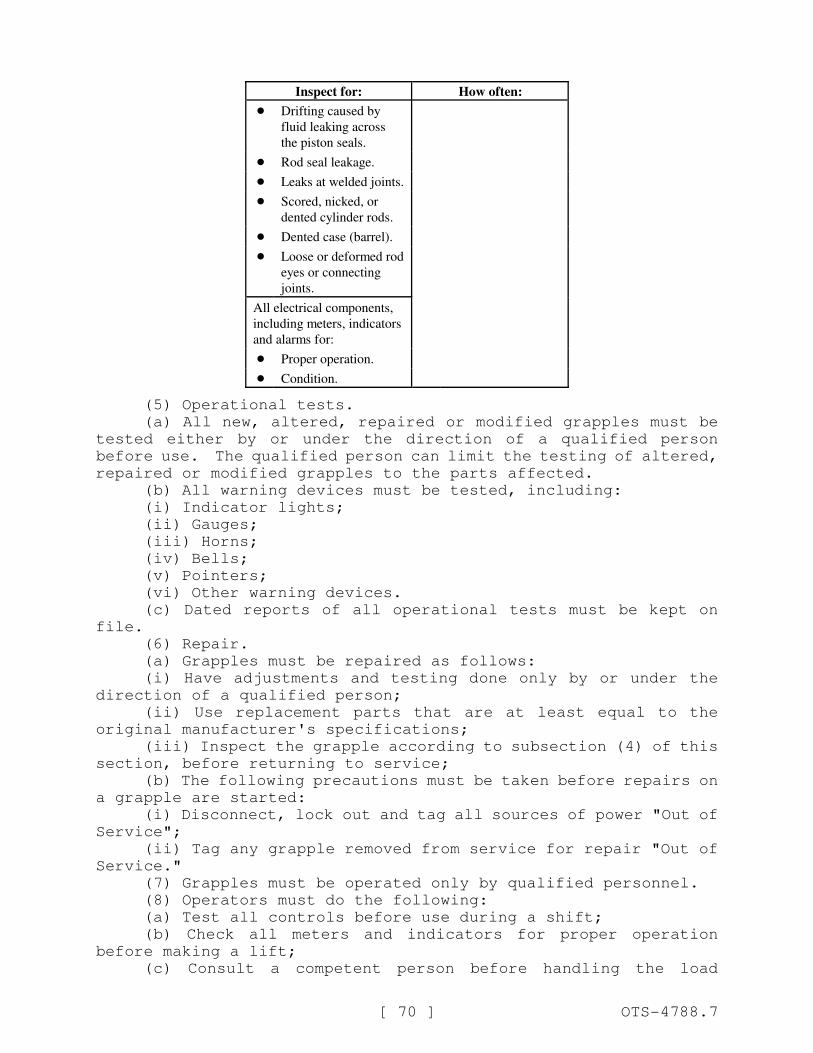
Inspect for: How often:
[ 70 ] OTS-4788.7
! Drifting caused by
fluid leaking across
the piston seals.
! Rod seal leakage.
! Leaks at welded joints.
! Scored, nicked, or
dented cylinder rods.
! Dented case (barrel).
! Loose or deformed rod
eyes or connecting
joints.
All electrical components,
including meters, indicators
and alarms for:
! Proper operation.
! Condition.
(5) Operational tests.
(a) All new, altered, repaired or modified grapples must be
tested either by or under the direction of a qualified person
before use. The qualified person can limit the testing of altered,
repaired or modified grapples to the parts affected.
(b) All warning devices must be tested, including:
(i) Indicator lights;
(ii) Gauges;
(iii) Horns;
(iv) Bells;
(v) Pointers;
(vi) Other warning devices.
(c) Dated reports of all operational tests must be kept on
file.
(6) Repair.
(a) Grapples must be repaired as follows:
(i) Have adjustments and testing done only by or under the
direction of a qualified person;
(ii) Use replacement parts that are at least equal to the
original manufacturer's specifications;
(iii) Inspect the grapple according to subsection (4) of this
section, before returning to service;
(b) The following precautions must be taken before repairs on
a grapple are started:
(i) Disconnect, lock out and tag all sources of power "Out of
Service";
(ii) Tag any grapple removed from service for repair "Out of
Service."
(7) Grapples must be operated only by qualified personnel.
(8) Operators must do the following:
(a) Test all controls before use during a shift;
(b) Check all meters and indicators for proper operation
before making a lift;
(c) Consult a competent person before handling the load
[ 71 ] OTS-4788.7
whenever there is any doubt as to safety;
(d) Respond only to instructions from competent persons,
except for stop orders. An operator must obey a stop order at all
times, no matter who gives it;
(e) Do not load grapples in excess of the rated load or with
any load that they are not specifically designed for;
(f) Apply the grapple to the load according to the instruction
manual;
(g) Bring the grapple over the load in a way that minimizes
swinging;
(h) Keep the load or grapple from contact with any
obstruction;
(i) Set down any attached load and store the grapple before
leaving it;
(j) Don't let anyone ride on loads or the grapple;
(k) Check that all people stay clear of the load.
AMENDATORY SECTION (Amending WSR 08-22-080, filed 11/4/08,
effective 1/1/10)
WAC 296-155-529 ((Crane certifier accreditation and crane
certification.)) Scope and definitions.
AMENDATORY SECTION (Amending WSR 12-01-086, filed 12/20/11,
effective 2/1/12)
WAC 296-155-52900 Scope. (1) Except as provided in
subsection (3) of this section, this part applies to the following:
(a) Power-operated cranes and derricks used in construction
that can hoist, lower and horizontally move a suspended load (with
or without attachments). Such equipment includes, but is not
limited to: Articulating boom cranes (such as knuckle-boom
cranes); crawler cranes; floating cranes; cranes on barges;
locomotive cranes; mobile cranes (such as wheel-mounted, rough-
terrain, all-terrain, commercial truck-mounted, and boom truck
cranes); multipurpose machines when configured to hoist and lower
(by means of a winch or hook) and horizontally move a suspended
load; industrial cranes (such as carry-deck cranes); cranes being
used as dedicated pile drivers; service/mechanic trucks with a
hoisting device; a crane on a monorail; tower cranes (such as fixed
jib ("hammerhead boom"), luffing boom and self-erecting); pedestal
cranes; portal cranes; overhead/bridge and gantry cranes; straddle
cranes; side-boom tractors; derricks; and variations of such
equipment((.)); and
[ 72 ] OTS-4788.7
(b) Personnel lifting with attached or suspended platforms
using cranes or derricks (WAC 296-155-547).
(2) Attachments. This standard applies to equipment included
in subsection (1) of this section when used with attachments. Such
attachments, whether crane-attached or suspended include, but are
not limited to:
! Hooks;
! Magnets;
! Grapples;
! Clamshell buckets;
! Orange peel buckets;
! Concrete buckets;
! Draglines;
! Personnel platforms;
! Augers or drills; and
! Pile driving equipment.
(3) The equipment listed below are exempted from WAC ((296-
155-529)) 296-155-531 and 296-155-532 (Crane certifier
accreditation and crane certification) through 296-155-53300
(Operator qualifications and certification):
(a) Cranes having a maximum rated capacity of one ton or less
((are exempt from this rule for the purposes of crane certification
and operator certification)). See WAC 296-155-53414 for additional
requirements.
(b) ((Equipment included in subsection (1) of this section
while it has been converted or adapted for nonhoisting/lifting use.
Such conversions/adaptations include, but are not limited to, power
shovels, excavators and concrete pumps.
(c) Power shovels, excavators, wheel loaders, backhoes, loader
backhoes, track loaders. This machinery is also excluded when used
with chains, slings or other rigging to lift suspended loads. For
rigging requirements see WAC 296-155-556 through 296-155-562.
(d) Automotive wreckers and tow trucks when used to clear
wrecks and haul vehicles.
(e) Digger derricks when used for activities that are covered
under chapter 296-45 WAC, Safety standards for electrical workers,
or chapter 296-32 WAC, Safety standards for telecommunications.
Cranes other than digger derricks when used for activities that are
covered under chapter 296-45 WAC, Safety standards for electrical
workers, or chapter 296-32 WAC, Safety standards for
telecommunications are NOT exempt.
(f) Equipment originally designed as vehicle-mounted aerial
devices (for lifting personnel) and self-propelled elevating work
platforms.
(g) Hydraulic jacking systems, including telescopic/hydraulic
gantries.
(h) Stacker cranes.
(i))) Powered industrial trucks (forklifts) ((except)) when
configured to hoist and lower (by means of a winch or hook) and
horizontally move a suspended load((. (Powered industrial trucks
including their attachments do not need to be certified by an
accredited certifier)) are exempted from WAC 296-155-532 (crane
certification). Operators must also follow the requirements in
[ 73 ] OTS-4788.7
chapter 296-863 WAC, Forklifts and other powered industrial trucks
((and WAC 296-155-53300 of this chapter.)
(j) Mechanic's truck with a hoisting device when used in
activities related to equipment maintenance and repair.
(k) Equipment that hoists by using a come-a-long or chainfall.
(l) Overhead/bridge cranes or hoists that travel or trolley
manually.
(m) Dedicated drilling rigs.
(n) Gin poles used for the erection of communication towers.
(o) Tree trimming and tree removal work.
(p) Anchor handling or dredge-related operations with a vessel
or barge using an affixed A-frame.
(q) Roustabouts)).
(((r))) (c) Service cranes with booms that rotate manually.
(((s) Machines equipped with a boom that is limited to up and
down movement only and does not rotate.
(t) Conveyors.
(u) Pump hoists with booms that do not rotate.
(v) Permanently installed overhead/bridge, gantry cranes,
semigantry, cantilever gantry, wall cranes, storage bridge cranes,
and others having the same fundamental characteristics which are
located in manufacturing facilities or powerhouses.
(w) Cranes and their operators used on-site in manufacturing
facilities or powerhouses for occasional or routine maintenance and
repair work.
(x) Helicopter cranes.
(4) Digger derricks that do not meet the exemption criteria in
subsection (3)(e) of this section must comply with WAC 296-155-529
(Crane certifier accreditation and crane certification) through WAC
296-155-53300 (Operator qualifications and certification) one
hundred eighty days after the effective date of this section.))
(4) The equipment listed below are exempt from this part:
(a) Equipment included in subsection (1) of this section while
it has been converted or adapted for nonhoisting/lifting use. Such
conversions/adaptations include, but are not limited to, power
shovels, excavators and concrete pumps.
(b) Power shovels, excavators, wheel loaders, backhoes, loader
backhoes, track loaders. This machinery is also excluded when used
with chains, slings or other rigging to lift suspended loads.
(c) Automotive wreckers and tow trucks when used to clear
wrecks and haul vehicles.
(d) Equipment originally designed as vehicle-mounted aerial
devices (for lifting personnel) and self-propelled elevating work
platforms.
(e) Hydraulic jacking systems, including telescopic/hydraulic
gantries.
(f) Stacker cranes.
(g) Mechanic's truck with a hoisting device when used in
activities related to equipment maintenance and repair.
(h) Equipment that hoists by using a come-a-long or chainfall.
(i) Dedicated drilling rigs.
(j) Gin poles used for the erection of communication towers.
(k) Tree trimming and tree removal work.
[ 74 ] OTS-4788.7
(l) Anchor handling or dredge-related operations with a vessel
or barge using an affixed A-frame.
(m) Roustabouts.
(n) Machines equipped with a boom that is limited to up and
down movement only and does not rotate.
(o) Conveyors.
(p) Pump hoists with booms that do not rotate.
(q) Cranes and their operators used on-site in manufacturing
facilities or powerhouses for occasional or routine maintenance and
repair work.
(r) Helicopter cranes.
(s) Permanently installed overhead/bridge, gantry cranes,
semi-gantry, cantilever gantry, wall cranes, storage bridge cranes,
and others having the same fundamental characteristics.
(t) Digger derricks when used for activities that are covered
under chapter 296-45 WAC, Safety standards for electrical workers,
or chapter 296-32 WAC, Safety standards for telecommunications.
Cranes other than digger derricks when used for activities that are
covered under chapter 296-45 WAC, Safety standards for electrical
workers, or chapter 296-32 WAC, Safety standards for
telecommunications are NOT exempt.
(u) Powered industrial trucks (forklifts) except when
configured to hoist and lower (by means of a winch or hook) and
horizontally move a suspended load.
Note: Rigging requirements for material handling is located in Part F-1 of this chapter.
(5) Digger derricks that do not meet the exemption criteria in
subsection (4) of this section must comply with WAC 296-155-531
(crane certifier accreditation and crane certification) through WAC
296-155-53300 (Operator qualifications and certification) one
hundred eighty days after the effective date of this section.
(((5))) (6) Where provisions of this standard direct an
operator, crewmember, or other employee to take certain actions,
the employer must establish, effectively communicate to the
relevant persons, and enforce work rules, to ensure compliance with
such provisions.
(((6))) (7) Work covered by chapter 296-45 WAC, Safety
standards for electrical workers is deemed in compliance with WAC
296-155-53408.
(((7))) (8) WAC 296-155-53400 (35) through (39) does not apply
to cranes designed for use on railroad tracks, when used on
railroad tracks that are used as part of the general railroad
system of transportation that is regulated pursuant to the Federal
Railroad Administration under C.F.R. 49, Part 213, and that comply
with applicable Federal Railroad Administration requirements. See
WAC 296-155-53400(39).
[ 75 ] OTS-4788.7
AMENDATORY SECTION (Amending WSR 12-01-086, filed 12/20/11,
effective 2/1/12)
WAC 296-155-52902 Definitions. Accredited crane certifiermeans a crane inspector who has been accredited by the department.
A/D director (assembly/disassembly) director means an
individual who meets the requirements in this part for an A/D
director, irrespective of the person's formal job title or whether
the person is nonmanagement or management personnel.
Angle of loading means the acute angle between horizontal andthe leg of the rigging, often referred to as horizontal angle. See
Figures 18 and 33.
Anti two-block device means a device that, when activated,disengages all crane functions whose movement can cause two-
blocking.
Apprentice operator or trainee means a crane operator who hasnot met requirements established by the department under RCW
49.17.430.
Articulating boom crane means a crane whose boom consists ofa series of folding, pin connected structural members, typically
manipulated to extend or retract by power from hydraulic cylinders.
Assembly/disassembly means the assembly and/or disassembly ofcomponents or attachments covered under this part. With regard to
tower cranes, "erecting and climbing" replaces the term "assembly,"
and "dismantling" replaces the term "disassembly." Regardless of
whether the crane is initially erected to its full height or is
climbed in stages, the process of increasing height of the crane is
an erection process.
Assist crane means a crane used to assist in assembling ordisassembling a crane.
Attachments mean((s)) any device that expands the range ((or))of tasks that can be done by the crane/derrick. Examples include,
but are not limited to: An auger, drill, magnet, pile-driver, and
boom-attached personnel platform.
Audible signal means a signal made by a distinct sound orseries of sounds. Examples include, but are not limited to, sounds
made by a bell, horn, or whistle.
Basket hitch means a method of rigging a sling in which thesling is passed around the load and both loop eyes or end fittings
are attached to the lifting device.
Below-the-hook lifting device means a device used for
attaching loads to a hoist. The device may contain components such
as slings, hooks, rigging hardware, and lifting attachments.
Bird caging means the twisting of fiber or wire rope in anisolated area of the rope in the opposite direction of the rope
lay, thereby causing it to take on the appearance of a bird cage.
Blocking (also referred to as "cribbing") means wood or othermaterial used to support equipment or a component and distribute
loads to the ground. It is typically used to support latticed boom
sections during assembly/disassembly and under outrigger and
stabilizer floats.
Boatswain's chair means a single-point adjustable suspension
[ 76 ] OTS-4788.7
scaffold consisting of a seat or sling (which may be incorporated
into a full body harness) designed to support one employee in a
sitting position.
Bogie. See "travel bogie."
Boom (other than tower crane) means an inclined spar, strut,or other long structural member which supports the upper hoisting
tackle on a crane or derrick. Typically, the length and vertical
angle of the boom can be varied to achieve increased height or
height and reach when lifting loads. Booms can usually be grouped
into general categories of hydraulically extendible, cantilevered
type, latticed section, cable supported type or articulating type.
Boom (tower cranes) on tower cranes: If the "boom" (i.e.,principal horizontal structure) is fixed, it is referred to as a
jib; if it is moveable up and down, it is referred to as a boom.
Boom angle indicator means a device which measures the angleof the boom relative to horizontal.
Boom hoist limiting device includes boom hoist disengagingdevice, boom hoist shut-off, boom hoist disconnect, boom hoist
hydraulic relief, boom hoist kick-outs, automatic boom stop device,
or derricking limiter. This type of device disengages boom hoist
power when the boom reaches a predetermined operating angle. It
also sets brakes or closes valves to prevent the boom from lowering
after power is disengaged.
Boom length indicator indicates the length of the permanentpart of the boom (such as ruled markings on the boom) or, as in
some computerized systems, the length of the boom with
extensions/attachments.
Boom stop includes boom stops (belly straps with
struts/standoff), telescoping boom stops, attachment boom stops,
and backstops. These devices restrict the boom from moving above
a certain maximum angle and toppling over backward.
Boom suspension systems means a system of pendants, runningropes, sheaves, and other hardware which supports the boom tip and
controls the boom angle.
Braided wire rope means a wire rope formed by plaiting
component wire ropes.
Bridle wire rope sling means a sling composed of multiple legswith the top ends gathered in a fitting that goes over the lifting
hook.
Builder means the builder/constructor of derricks.
Cable laid endless sling-mechanical joint means a wire ropesling made endless from one continuous length of cable laid rope
with the ends joined by one or more metallic fittings.
Cable laid grommet-hand tucked means an endless wire ropesling made from one continuous length of rope formed to make a body
composed of six ropes around a rope core. The rope ends are tucked
into the body, thus forming the core. No sleeves are used.
Center of gravity means the center of gravity of any object isthe point in the object around which its weight is evenly
distributed. If you could put a support under that point, you
could balance the object on the support.
Certified crane inspector means a crane certifier accredited
[ 77 ] OTS-4788.7
by the department.
Certified welder means a welder who meets nationally
recognized certification requirements applicable to the task being
performed.
Choker hitch means a method of rigging a sling in which thesling is passed around the load, then through one loop eye, end
fitting, or other device, with the other loop eye or end fitting
attached to the lifting device. This hitch can be done with a
sliding choker hook or similar device.
Climbing means the process in which a tower crane is raised orlowered to a new working height, either by adding or removing tower
sections to the top of the crane (top climbing), or by a system in
which the entire crane is raised or lowered inside the structure
(inside climbing).
Come-a-long means a mechanical device typically consisting ofa chain or cable attached at each end that is used to facilitate
movement of materials through leverage.
Competent person means one who is capable of identifying
existing and predictable hazards in the surroundings or working
conditions which are unsanitary, hazardous, or dangerous to
employees, and who has authorization to take prompt corrective
measures to eliminate them.
Construction work means (for the purposes of this part) all orany part of excavation, construction, erection, alteration, repair,
demolition, and dismantling of buildings and other structures and
all related operations; the excavation, construction, alteration,
and repair of sewers, trenches, caissons, conduits, pipelines,
roads, and all related operations; the moving of buildings and
other structures, and the construction, alteration, repair, or
removal of wharfs, docks, bridges, culverts, trestles, piers,
abutments, or any other related construction, alteration, repair,
or removal work. Construction work does not include the normal
day-to-day activities at manufacturing facilities or powerhouses.
Controlled load lowering means lowering a load by means of amechanical hoist drum device that allows a hoisted load to be
lowered with maximum control using the gear train or hydraulic
components of the hoist mechanism. Controlled load lowering
requires the use of the hoist drive motor, rather that the load
hoist brake, to lower the load.
Controlling entity means an employer that is a prime
contractor, general contractor, construction manager or any other
legal entity which has the overall responsibility for the
construction of the projects, its planning, quality, and
completion.
Counterjib (counterweight jib) means a horizontal member ofthe tower crane on which the counterweights and usually the
hoisting machinery are mounted.
Counterweight means weight used to supplement the weight ofequipment in providing stability for lifting loads by
counterbalancing those loads.
Crane means power-operated equipment used in construction thatcan hoist, lower, and horizontally move a suspended load. "Crane"
[ 78 ] OTS-4788.7
includes, but is not limited to: Articulating boom cranes, such as
knuckle-boom cranes; crawler cranes; floating cranes; cranes on
barges; locomotive cranes; mobile cranes, such as wheel-mounted,
rough-terrain, all-terrain, commercial truck mounted, and boom
truck cranes; multipurpose machines when configured to hoist and
lower by means of a winch or hook and horizontally move a suspended
load; industrial cranes, such as carry-deck cranes; dedicated pile
drivers; service/mechanic trucks with a hoisting device; a crane on
a monorail; tower cranes, such as fixed jib, hammerhead boom,
luffing boom, and self-erecting; pedestal cranes; portal cranes;
overhead and gantry cranes; straddle cranes; side-boom tractors;
derricks; and variations of such equipment.
Crane/derrick type means cranes or derricks as established byAmerican Society of Mechanical Engineers (ASME). Crane operator
means an individual engaged in the operation of a crane.
Crane level indicator means a device for determining truehorizontal (also see safety devices).
Crawler crane means equipment that has a type of base mountingwhich incorporates a continuous belt of sprocket driven track.
Critical lift means a lift that:! Exceeds seventy-five percent of the crane or derrick rated
load chart capacity; or
! Requires the use of more than one crane or derrick.
Cross rod means a wire used to join spirals of metal mesh toform a complete fabric. See Figure 22.
Crossover points means locations on a wire rope which isspooled on a drum where one layer of rope climbs up on and crosses
over the previous layer. This takes place at each flange of the
drum as the rope is spooled onto the drum, reaches the flange, and
begins to wrap back in the opposite direction.
Dedicated channel means a line of communication assigned bythe employer who controls the communication system to only one
signal person and crane/derrick or to a coordinated group of
cranes/derricks/signal persons.
Dedicated drilling rig means a machine which creates boreholes and/or shafts in the ground.
Dedicated pile-driver is a machine that is designed to
function exclusively as a pile-driver. These machines typically
have the ability to both hoist the material that will be pile-
driven and to pile-drive that material.
Dedicated spotter (power lines): To be considered a dedicatedspotter, the requirements of WAC 296-155-53302 (Signal person
qualifications) must be met and his/her sole responsibility is to
watch the separation between the power line and the equipment, the
load line and load (including rigging and lifting accessories), and
ensure through communication with the operator that the applicable
minimum approach distance is not breached.
Derrick is an apparatus consisting of a mast or equivalentmember held at the end by guys or braces, with or without a boom,
for use with a hoisting mechanism and operating ropes.
Design factor means the ratio between nominal or minimum
breaking strength and rated load.
[ 79 ] OTS-4788.7
Digger derrick means a multipurpose vehicle-mounted machinewhich is primarily designed to accommodate components that dig
holes, set poles, and position materials and apparatus.
Directly under the load means a part or all of an employee isdirectly beneath the load.
Dismantling includes partial dismantling (such as dismantlingto shorten a boom or substitute a different component).
Drum rotation indicator is a device on a crane or hoist whichindicates in which direction and at what relative speed a
particular hoist drum is turning.
Electrical contact means when a person, object, or equipmentmakes contact or comes close in proximity with an energized
conductor or equipment that allows the passage of current.
Employer-made equipment means floating cranes/derricks
designed and built by an employer for the employer's own use.
Encroachment is where any part of the crane, load line or load(including rigging and lifting accessories) breaches a minimum
clearance distance that this part requires to be maintained from a
power line.
Equipment criteria means instructions, recommendations,
limitations and specifications.
Fabric (metal mesh) means the flexible portion of the slingexclusive of end fittings consisting of a series of transverse
spirals and cross rods.
Fall protection equipment means guardrail systems, safety netsystems, personal fall arrest systems, positioning device systems
or fall restraint systems.
Fall restraint system means a fall protection system thatprevents the user from falling any distance. The system is
comprised of either a body belt or body harness, along with an
anchorage, connectors, and other necessary equipment. The other
components typically include a lanyard, and may also include a
lifeline and other devices.
Fall zone means the area (including, but not limited to, thearea directly beneath the load) in which it is reasonably
foreseeable that partially or completely suspended materials could
fall in the event of an accident.
Flange points means a point of contact between rope and drumflange where the rope changes layers.
Floating cranes/derricks means equipment designed by the
manufacturer (or employer) for marine use by permanent attachment
to a barge, pontoons, vessel or other means of flotation.
Free fall (of the load line) means when only the brake is usedto regulate the descent of the load line (the drive mechanism is
not used to drive the load down faster or retard its lowering).
Free rated load test means testing stability and operation ofcrane, carrier, wheels, tires, tracks, brakes, etc., under load,
when lifting without outriggers and/or traveling with the load are
permitted at the activity for the type of crane being tested.
Free surface effect is the uncontrolled transverse movement ofliquids in compartments which reduce a vessel's transverse
[ 80 ] OTS-4788.7
stability.
Functional testing means the testing of a crane, typicallydone with a light load or no load, to verify the proper operation
of a crane's primary function, i.e., hoisting, braking, booming,
swinging, etc. A functional test is contrasted to testing the
crane's structural integrity with heavy loads.
Gin pole derrick means a boom without a mast which has guysarranged from its top to permit leaning the mast in one or more
directions. The load is lifted and lowered by ropes reeved through
sheaves or blocks at the top of the mast and the lower block.
Ground conditions means the ability of the ground to supportthe crane/derrick (including slope, compaction, and firmness).
Ground crew means those individuals who are involved in thepersonnel lift, other than the hoisting equipment operator and the
platform occupants. These individuals include riggers, signal
persons, and supervision.
Gudgeon pins means a pin connecting the mast cap to the mastallowing rotation of the mast.
Guy means a rope used to steady or secure the mast, boom, orother member in the desired position.
Hairpin anchors means a hairpin-shaped, guy-supporting anchorthat is placed in footings or walls before concrete is poured and
held in place by the cured concrete.
Hitch (hitched) means a method of rigging (attaching) a slingtemporarily to a load or object for the purpose of lifting.
Hoist means a mechanical device for lifting and lowering loadsby winding rope onto or off a drum.
Hoisting means the act of raising, lowering or otherwise
moving a load in the air with equipment covered by this standard.
As used in this standard, "hoisting" can be done by means other
than wire rope/hoist drum equipment.
Hoisting equipment means a machine for lifting and lowering aload and moving it horizontally. The machine may be fixed or
mobile and be driven manually, by power, or by a combination of
both.
Hook latch means a mechanical device used to close the throatopening of a hook.
Insulating link/device means an insulating device listed,
labeled, or accepted by a nationally recognized testing laboratory
in accordance with 29 C.F.R. 1910.7.
Intermediate rail means the middle member of a barrier alongthe edges of a platform, located approximately one-half the
distance between the platform floor and top rail.
Jib means an extension attached to the boom point to provideadded boom length for lifting specified loads. The jib may be in
line with the boom or offset to various angles in the vertical
plane of the boom. For tower cranes, see boom (tower cranes).
Jib stop (also referred to as a jib backstop), is the sametype of device as a boom stop but is for a fixed or luffing jib.
Land crane/derrick means equipment not originally designed bythe manufacturer for marine use by permanent attachment to barges,
[ 81 ] OTS-4788.7
pontoons, vessels, or other means of flotation.
List means the angle of inclination about the longitudinalaxis of a barge, pontoons, vessel, or other means of flotation.
Live boom means a boom whose lowering is controlled by a brakewithout the aid of other lowering retarding devices (free-fall
capable).
Live load line means a load line whose lowering is controlledby a brake without the aid of other lowering retarding devices
(free-fall capable).
Load is the weight of the object being lifted or lowered,including the weight of the load-attaching equipment such as the
load block, ropes, slings, shackles, and any other auxiliary
attachment.
Load moment (or rated capacity) indicator means a system whichaids the equipment operator by sensing the overturning moment on
the equipment, i.e., load X radius. It compares this lifting
condition to the equipment's rated capacity, and indicates to the
operator the percentage of capacity at which the equipment is
working. Lights, bells, or buzzers may be incorporated as a
warning of an approaching overload condition.
Load moment (or rated capacity) limiter means a system whichaids the equipment operator by sensing the overturning moment on
the equipment, i.e., load X radius. It compares this lifting
condition to the equipment's rated capacity, and when the rated
capacity is reached, it shuts off power to those equipment
functions which can increase the severity of loading on the
equipment, e.g., hoisting, telescoping out, or luffing out.
Typically, those functions which decrease the severity of loading
on the equipment remain operational, e.g., lowering, telescoping
in, or luffing in.
Load ratings means a set of rated loads for stipulated
hoisting equipment configurations and operating conditions.
Load sustaining/bearing parts means those parts of a cranethat support the crane or load and upon failure could cause
dropping, uncontrolled shifting, or uncontrolled movement of the
crane or load.
Locomotive crane means a crane mounted on a base or car
equipped for travel on a railroad track.
Luffing boom is a member hinged to the rotating superstructureand used for supporting the hoisting tackle.
Luffing jib limiting device is similar to a boom hoist
limiting device, except that it limits the movement of the luffing
jib.
Marine worksite means a construction worksite located in, onor above the water.
Master coupling link means an alloy steel welded coupling linkused as an intermediate link to join alloy steel chain to master
links.
Master link means forged or welded steel link used to supportall members (legs) of an alloy steel chain sling or wire rope
sling.
Mechanical coupling link (alloy steel chain) means a
[ 82 ] OTS-4788.7
nonwelded, mechanically closed link used primarily to attach
fittings to alloy steel chain.
Mobile cranes means a lifting device incorporating a cablesuspended latticed boom or hydraulic telescopic boom designed to be
moved between operating locations by transport over the road.
((These are referred to in Europe as a crane mounted on a truck
carrier.))
Moving point-to-point means the times during which an employeeis in the process of going to or from a work station.
Multipurpose machine means a machine that is designed to beconfigured in various ways, at least one of which allows it to
hoist (by means of a winch or hook) and horizontally move a
suspended load. For example, a machine that can rotate and can be
configured with removable forks/tongs (for use as a forklift) or
with a winch pack, jib (with a hook at the end) or jib used in
conjunction with a winch. When configured with the forks/tongs, it
is not covered by this part. When configured with a winch pack,
jib (with a hook at the end) or jib used in conjunction with a
winch, it is covered by this part.
Multiple lift rigging means a rigging assembly manufactured bywire rope rigging suppliers that facilitates the attachment of up
to five independent loads to the hoist rigging of a crane.
Nationally recognized accrediting agency is an organizationthat, due to its independence and expertise, is widely recognized
as competent to accredit testing organizations.
Nonconductive means that, because of the nature and conditionof the materials used, and the conditions of use (including
environmental conditions and condition of the material), the object
in question has the property of not becoming energized (that is, it
has high dielectric properties offering a high resistance to the
passage of current under the conditions of use).
Nonstandard tower crane base means any deviation from thestructural support or base configuration recommended by the crane
manufacturer.
Occasional or routine maintenance and repair work means
regular, customary and foreseeable work necessary to keep equipment
in good repair and/or condition. This also includes regular,
customary and foreseeable work necessary to return equipment to
sound condition after damage.
Operational aid means an accessory that provides informationto facilitate operation of a crane or that takes control of
particular functions without action of the operator when a limiting
condition is sensed. Examples of such devices include, but are not
limited to, the following: Anti-two-block device, rated capacity
indicator, rated capacity (load) limiter, boom angle or radius
indicator, lattice boom hoist disconnect device, boom length
indicator, drum rotation indicator, load indicator, and wind speed
indicator.
Operational controls means levers, switches, pedals and otherdevices for controlling equipment operation.
Operator is a person who is operating the equipment.
Outriggers means extendable or fixed members attached to the
[ 83 ] OTS-4788.7
mounting base, which rests on supports at the outer ends, used to
support the crane.
Overhead/bridge and gantry cranes includes overhead/bridgecranes, cranes on monorails, under hung cranes, semigantry,
cantilever gantry, wall cranes, storage bridge cranes, launching
gantry cranes, and similar equipment, irrespective of whether it
travels on tracks, wheels, or other means.
Pendants includes both wire and bar types. Wire type: Afixed length of wire rope with mechanical fittings at both ends for
pinning segments of wire rope together. Bar type: Instead of wire
rope, a bar is used. Pendants are typically used in a latticed
boom crane system to easily change the length of the boom
suspension system without completely changing the rope on the drum
when the boom length is increased or decreased.
Personal fall arrest system means a system used to arrest anemployee in a fall from a working level. It consists of an
anchorage, connectors, and a body harness and may include a
lanyard, deceleration device, lifeline, or suitable combination of
these.
Personnel lifting means raising, lowering, or transportingpersonnel using a crane/derrick.
Personnel platform - Boom attached means a platform attachedto the boom of the crane.
Personnel platform - Suspended means a platform attached to acrane/derrick using wire rope, chain, or a jointed attachment and
that has no installed motion controls for the platform itself.
Personnel platform suspension system means the rope or chainslings and other components, including fastening devices, used to
connect the crane/derrick to the personnel platform.
Platform occupant means a person who is within the guardrailbarrier while the personnel platform is in a hoisted position.
Platform rating means the maximum capacity of a personnellifting platform, established by the platform manufacturer, in
terms of total weight and the number of occupants allowed.
Portal crane is a type of crane consisting of a rotating upperstructure, hoist machinery, and boom mounted on top of a structural
gantry which may be fixed in one location or have travel
capability. The gantry legs or columns usually have portal
openings in between to allow passage of traffic beneath the gantry.
Power controlled lowering means a system or device in thepower train, other than the load hoist brake, that can regulate the
lowering rate of speed of the load hoist mechanism.
Powerhouse means a plant wherein electric energy is producedby conversion from some other form of energy (e.g., chemical,
nuclear, solar, mechanical, or hydraulic) by means of suitable
apparatus. This includes all generating station auxiliaries and
other associated equipment required for the operation of the plant.
Not included are stations producing power exclusively for use with
communication systems.
Power lines means electrical distribution and electrical
transmission lines.
Procedures include, but are not limited to: Instructions,
[ 84 ] OTS-4788.7
diagrams, recommendations, warnings, specifications, protocols, and
limitations.
Proximity alarm is a device that provides a warning of
proximity to a power line that has been listed, labeled or accepted
by a nationally recognized testing laboratory in accordance with 29
C.F.R. 1910.7.
Qualified crane operator means a crane operator who meets therequirements established by the department under RCW 49.17.430.
Qualified evaluator (not a third party) means a person
employed by the signal person's or the rigger's employer (as
applicable) who has demonstrated that he/she is competent in
accurately assessing whether individuals meet the qualification
requirements in this part for a signal person or a rigger.
Qualified evaluator (third party) means an entity that, due toits independence and expertise, has demonstrated that it is
competent in accurately assessing whether individuals meet the
qualification requirements in this part for a signal person or a
rigger.
Qualified person means a person who, by possession of a
recognized degree, certificate, or professional standing, or who by
extensive knowledge, training and experience, successfully
demonstrated the ability to solve/resolve problems relating to the
subject matter, the work, or the project.
Qualified rigger is a rigger who meets the requirements in WAC296-155-53306.
Qualified signal person is a signal person who meets therequirements in WAC 296-155-53302.
Range control limit device is a device that can be set by anequipment operator to limit movement of the boom or jib tip to a
plane or multiple planes.
Range control warning device is a device that can be set by anequipment operator to warn that the boom or jib tip is at a plane
or multiple planes.
Rated capacity means the maximum working load permitted by themanufacturer under specified working conditions. Such working
conditions typically include a specific combination of factors such
as equipment configuration, radii, boom length, and other
parameters of use.
Rated capacity indicator, see load moment indicator.
Rated capacity limiter, see load moment limiter.
Repetitive pickup points refer to, when operating on a shortcycle operation, the rope being used on a single layer and being
spooled repetitively over a short portion of the drum.
Rotation resistant rope means a type of wire rope constructionwhich reduces the tendency of a rope to rotate about its axis under
load. Usually, this consists of an inner system of core strands
laid in one direction covered by an outer system of strands laid in
the opposite direction.
RPE means a registered professional engineer licensed underRCW 18.43.040(1).
RPSE means a registered professional structural engineer
licensed under RCW 18.43.040(1).
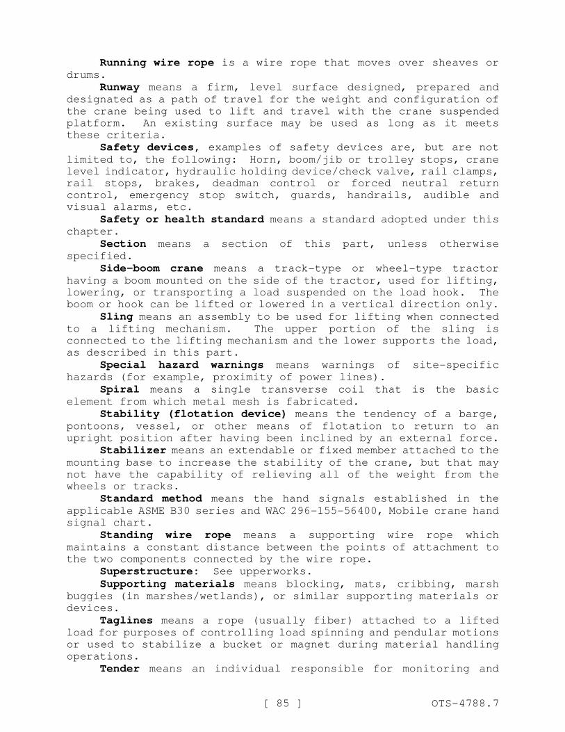
[ 85 ] OTS-4788.7
Running wire rope is a wire rope that moves over sheaves ordrums.
Runway means a firm, level surface designed, prepared anddesignated as a path of travel for the weight and configuration of
the crane being used to lift and travel with the crane suspended
platform. An existing surface may be used as long as it meets
these criteria.
Safety devices, examples of safety devices are, but are notlimited to, the following: Horn, boom/jib or trolley stops, crane
level indicator, hydraulic holding device/check valve, rail clamps,
rail stops, brakes, deadman control or forced neutral return
control, emergency stop switch, guards, handrails, audible and
visual alarms, etc.
Safety or health standard means a standard adopted under thischapter.
Section means a section of this part, unless otherwise
specified.
Side-boom crane means a track-type or wheel-type tractor
having a boom mounted on the side of the tractor, used for lifting,
lowering, or transporting a load suspended on the load hook. The
boom or hook can be lifted or lowered in a vertical direction only.
Sling means an assembly to be used for lifting when connectedto a lifting mechanism. The upper portion of the sling is
connected to the lifting mechanism and the lower supports the load,
as described in this part.
Special hazard warnings means warnings of site-specific
hazards (for example, proximity of power lines).
Spiral means a single transverse coil that is the basic
element from which metal mesh is fabricated.
Stability (flotation device) means the tendency of a barge,pontoons, vessel, or other means of flotation to return to an
upright position after having been inclined by an external force.
Stabilizer means an extendable or fixed member attached to themounting base to increase the stability of the crane, but that may
not have the capability of relieving all of the weight from the
wheels or tracks.
Standard method means the hand signals established in theapplicable ASME B30 series and WAC 296-155-56400, Mobile crane hand
signal chart.
Standing wire rope means a supporting wire rope which
maintains a constant distance between the points of attachment to
the two components connected by the wire rope.
Superstructure: See upperworks.
Supporting materials means blocking, mats, cribbing, marshbuggies (in marshes/wetlands), or similar supporting materials or
devices.
Taglines means a rope (usually fiber) attached to a liftedload for purposes of controlling load spinning and pendular motions
or used to stabilize a bucket or magnet during material handling
operations.
Tender means an individual responsible for monitoring and
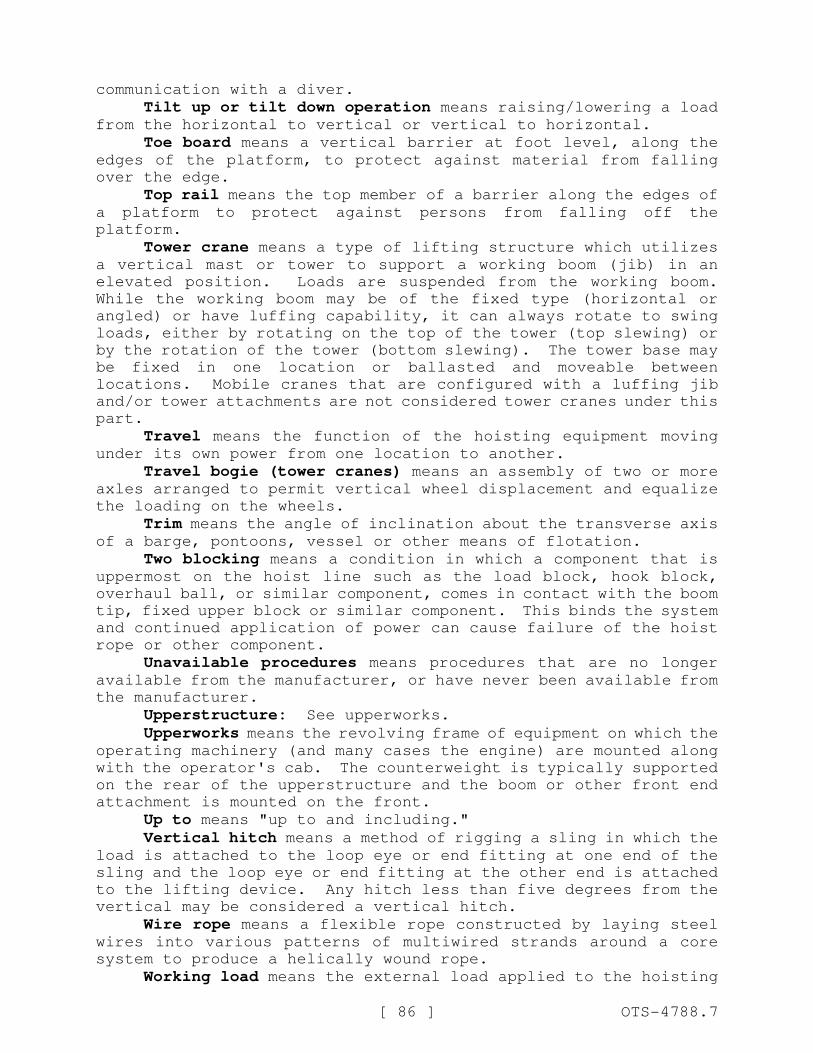
[ 86 ] OTS-4788.7
communication with a diver.
Tilt up or tilt down operation means raising/lowering a loadfrom the horizontal to vertical or vertical to horizontal.
Toe board means a vertical barrier at foot level, along theedges of the platform, to protect against material from falling
over the edge.
Top rail means the top member of a barrier along the edges ofa platform to protect against persons from falling off the
platform.
Tower crane means a type of lifting structure which utilizesa vertical mast or tower to support a working boom (jib) in an
elevated position. Loads are suspended from the working boom.
While the working boom may be of the fixed type (horizontal or
angled) or have luffing capability, it can always rotate to swing
loads, either by rotating on the top of the tower (top slewing) or
by the rotation of the tower (bottom slewing). The tower base may
be fixed in one location or ballasted and moveable between
locations. Mobile cranes that are configured with a luffing jib
and/or tower attachments are not considered tower cranes under this
part.
Travel means the function of the hoisting equipment movingunder its own power from one location to another.
Travel bogie (tower cranes) means an assembly of two or moreaxles arranged to permit vertical wheel displacement and equalize
the loading on the wheels.
Trim means the angle of inclination about the transverse axisof a barge, pontoons, vessel or other means of flotation.
Two blocking means a condition in which a component that isuppermost on the hoist line such as the load block, hook block,
overhaul ball, or similar component, comes in contact with the boom
tip, fixed upper block or similar component. This binds the system
and continued application of power can cause failure of the hoist
rope or other component.
Unavailable procedures means procedures that are no longeravailable from the manufacturer, or have never been available from
the manufacturer.
Upperstructure: See upperworks.
Upperworks means the revolving frame of equipment on which theoperating machinery (and many cases the engine) are mounted along
with the operator's cab. The counterweight is typically supported
on the rear of the upperstructure and the boom or other front end
attachment is mounted on the front.
Up to means "up to and including."
Vertical hitch means a method of rigging a sling in which theload is attached to the loop eye or end fitting at one end of the
sling and the loop eye or end fitting at the other end is attached
to the lifting device. Any hitch less than five degrees from the
vertical may be considered a vertical hitch.
Wire rope means a flexible rope constructed by laying steelwires into various patterns of multiwired strands around a core
system to produce a helically wound rope.
Working load means the external load applied to the hoisting
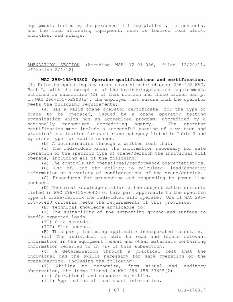
[ 87 ] OTS-4788.7
equipment, including the personnel lifting platform, its contents,
and the load attaching equipment, such as lowered load block,
shackles, and slings.
AMENDATORY SECTION (Amending WSR 12-01-086, filed 12/20/11,
effective 2/1/12)
WAC 296-155-53300 Operator qualifications and certification.(1) Prior to operating any crane covered under chapter 296-155 WAC,
Part L, with the exception of the trainee/apprentice requirements
outlined in subsection (2) of this section and those cranes exempt
in WAC 296-155-52900(3), the employer must ensure that the operator
meets the following requirements:
(a) Has a valid crane operator certificate, for the type of
crane to be operated, issued by a crane operator testing
organization which has an accredited program, accredited by a
nationally recognized accrediting agency. The operator
certification must include a successful passing of a written and
practical examination for each crane category listed in Table 3 and
by crane type for mobile cranes.
(b) A determination through a written test that:
(i) The individual knows the information necessary for safe
operation of the specific type of crane/derrick the individual will
operate, including all of the following:
(A) The controls and operational/performance characteristics.
(B) Use of, and the ability to calculate, load/capacity
information on a variety of configurations of the crane/derrick.
(C) Procedures for preventing and responding to power line
contact.
(D) Technical knowledge similar to the subject matter criteria
listed in WAC 296-155-56420 of this part applicable to the specific
type of crane/derrick the individual will operate. Use of WAC 296-
155-56420 criteria meets the requirements of this provision.
(E) Technical knowledge applicable to:
(I) The suitability of the supporting ground and surface to
handle expected loads.
(II) Site hazards.
(III) Site access.
(F) This part, including applicable incorporated materials.
(ii) The individual is able to read and locate relevant
information in the equipment manual and other materials containing
information referred to in (i) of this subsection.
(c) A determination through a practical test that the
individual has the skills necessary for safe operation of the
crane/derrick, including the following:
(i) Ability to recognize, from visual and auditory
observation, the items listed in WAC 296-155-53405(2).
(ii) Operational and maneuvering skills.
(iii) Application of load chart information.
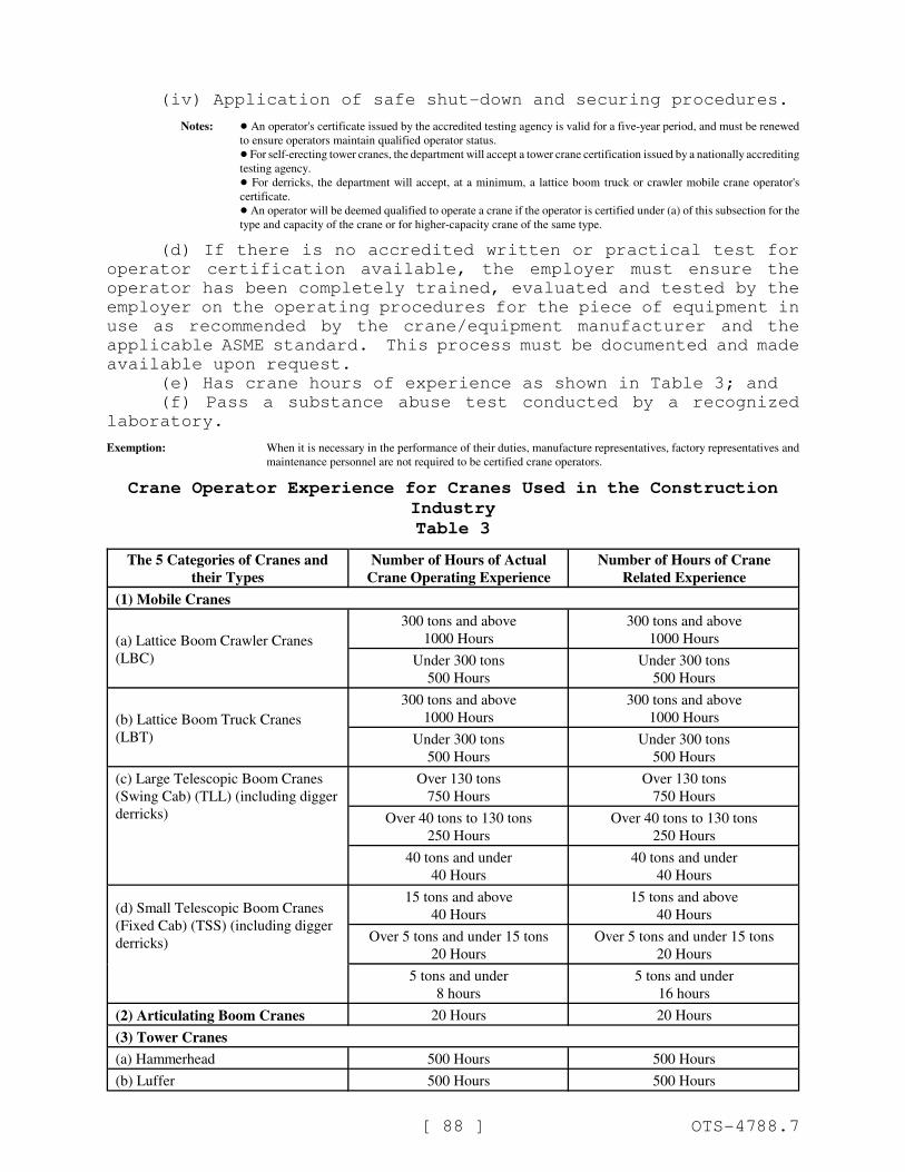
[ 88 ] OTS-4788.7
(iv) Application of safe shut-down and securing procedures.
Notes: ! An operator's certificate issued by the accredited testing agency is valid for a five-year period, and must be renewed
to ensure operators maintain qualified operator status.
! For self-erecting tower cranes, the department will accept a tower crane certification issued by a nationally accrediting
testing agency.
! For derricks, the department will accept, at a minimum, a lattice boom truck or crawler mobile crane operator's
certificate.
! An operator will be deemed qualified to operate a crane if the operator is certified under (a) of this subsection for the
type and capacity of the crane or for higher-capacity crane of the same type.
(d) If there is no accredited written or practical test for
operator certification available, the employer must ensure the
operator has been completely trained, evaluated and tested by the
employer on the operating procedures for the piece of equipment in
use as recommended by the crane/equipment manufacturer and the
applicable ASME standard. This process must be documented and made
available upon request.
(e) Has crane hours of experience as shown in Table 3; and
(f) Pass a substance abuse test conducted by a recognized
laboratory.
Exemption: When it is necessary in the performance of their duties, manufacture representatives, factory representatives and
maintenance personnel are not required to be certified crane operators.
Crane Operator Experience for Cranes Used in the Construction
Industry
Table 3
The 5 Categories of Cranes and
their Types
Number of Hours of Actual
Crane Operating Experience
Number of Hours of Crane
Related Experience
(1) Mobile Cranes
(a) Lattice Boom Crawler Cranes
(LBC)
300 tons and above
1000 Hours
300 tons and above
1000 Hours
Under 300 tons
500 Hours
Under 300 tons
500 Hours
(b) Lattice Boom Truck Cranes
(LBT)
300 tons and above
1000 Hours
300 tons and above
1000 Hours
Under 300 tons
500 Hours
Under 300 tons
500 Hours
(c) Large Telescopic Boom Cranes
(Swing Cab) (TLL) (including digger
derricks)
Over 130 tons
750 Hours
Over 130 tons
750 Hours
Over 40 tons to 130 tons
250 Hours
Over 40 tons to 130 tons
250 Hours
40 tons and under
40 Hours
40 tons and under
40 Hours
(d) Small Telescopic Boom Cranes
(Fixed Cab) (TSS) (including digger
derricks)
15 tons and above
40 Hours
15 tons and above
40 Hours
Over 5 tons and under 15 tons
20 Hours
Over 5 tons and under 15 tons
20 Hours
5 tons and under
8 hours
5 tons and under
16 hours
(2) Articulating Boom Cranes 20 Hours 20 Hours
(3) Tower Cranes
(a) Hammerhead 500 Hours 500 Hours
(b) Luffer 500 Hours 500 Hours
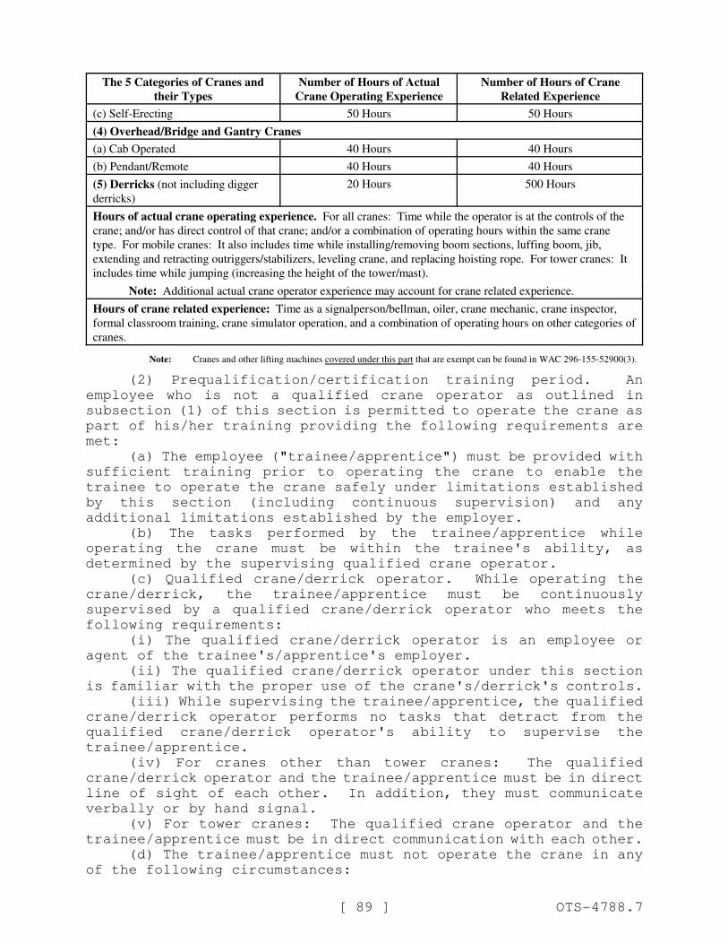
The 5 Categories of Cranes and
their Types
Number of Hours of Actual
Crane Operating Experience
Number of Hours of Crane
Related Experience
[ 89 ] OTS-4788.7
(c) Self-Erecting 50 Hours 50 Hours
(4) Overhead/Bridge and Gantry Cranes
(a) Cab Operated 40 Hours 40 Hours
(b) Pendant/Remote 40 Hours 40 Hours
(5) Derricks (not including digger
derricks)
20 Hours 500 Hours
Hours of actual crane operating experience. For all cranes: Time while the operator is at the controls of the
crane; and/or has direct control of that crane; and/or a combination of operating hours within the same crane
type. For mobile cranes: It also includes time while installing/removing boom sections, luffing boom, jib,
extending and retracting outriggers/stabilizers, leveling crane, and replacing hoisting rope. For tower cranes: It
includes time while jumping (increasing the height of the tower/mast).
Note: Additional actual crane operator experience may account for crane related experience.
Hours of crane related experience: Time as a signalperson/bellman, oiler, crane mechanic, crane inspector,
formal classroom training, crane simulator operation, and a combination of operating hours on other categories of
cranes.
Note: Cranes and other lifting machines covered under this part that are exempt can be found in WAC 296-155-52900(3).
(2) Prequalification/certification training period. An
employee who is not a qualified crane operator as outlined in
subsection (1) of this section is permitted to operate the crane as
part of his/her training providing the following requirements are
met:
(a) The employee ("trainee/apprentice") must be provided with
sufficient training prior to operating the crane to enable the
trainee to operate the crane safely under limitations established
by this section (including continuous supervision) and any
additional limitations established by the employer.
(b) The tasks performed by the trainee/apprentice while
operating the crane must be within the trainee's ability, as
determined by the supervising qualified crane operator.
(c) Qualified crane/derrick operator. While operating the
crane/derrick, the trainee/apprentice must be continuously
supervised by a qualified crane/derrick operator who meets the
following requirements:
(i) The qualified crane/derrick operator is an employee or
agent of the trainee's/apprentice's employer.
(ii) The qualified crane/derrick operator under this section
is familiar with the proper use of the crane's/derrick's controls.
(iii) While supervising the trainee/apprentice, the qualified
crane/derrick operator performs no tasks that detract from the
qualified crane/derrick operator's ability to supervise the
trainee/apprentice.
(iv) For cranes other than tower cranes: The qualified
crane/derrick operator and the trainee/apprentice must be in direct
line of sight of each other. In addition, they must communicate
verbally or by hand signal.
(v) For tower cranes: The qualified crane operator and the
trainee/apprentice must be in direct communication with each other.
(d) The trainee/apprentice must not operate the crane in any
of the following circumstances:
[ 90 ] OTS-4788.7
(i) If any part of the crane, load line or load (including
rigging and lifting accessories), if operated up to the crane's
maximum working radius in the work zone, could get within twenty
feet of a power line that is up to three hundred fifty kV, or
within fifty feet of a power line that is over three hundred fifty
kV;
(ii) If the crane is used to hoist personnel;
(iii) In a multiple-crane or multiple load line lift
situations; or
(iv) Multiple-lift rigging, as defined in WAC 296-155-52902,
can only be accomplished by the trainee/apprentice when the
qualified crane operator determines that the trainee's/apprentice's
skills are sufficient for this high-skill work.
(v) Critical lifts, as defined in WAC 296-155-52902, can only
be accomplished by the trainee/apprentice when the qualified crane
operator determines that the trainee's/apprentice's skills are
sufficient for this high-skill work.
(3) The employer must obtain documentation showing hours of
crane operator experience and crane related experience separated
out by crane type and capacity.
Note: The employer may accept a signed declaration from the crane operator attesting to actual hours of crane operator
experience and crane related experience separated out by crane type and capacity. For sample declaration form see WAC
296-155-56425.
(4) The department may recognize crane operator certification
from another state or territory of the United States as equivalent
to qualified crane operator requirements if the department
determines that the other jurisdiction's credentialing standards
are substantially similar to the qualified crane operator
requirements.
(5) Crane operator experience and crane related experience
must be documented and separated out by crane type and capacity;
this documentation need only show the minimum amount of hours as
outlined in Table 3 above. If the employer is documenting crane
operating and/or related crane experience hours, the employer must
provide a copy of the hours to the operator as soon as practical,
if requested.
AMENDATORY SECTION (Amending WSR 12-01-086, filed 12/20/11,
effective 2/1/12)
WAC 296-155-53306 Rigger qualifications. (1) The rigger mustmeet the qualification requirements (subsection (3) of this
section) prior to performing hoisting activities for assembly and
disassembly work (WAC 296-155-53402 (19)(a)). A qualified rigger
is required whenever ((workers)) employees are ((within the fall
zone and)) engaged in hooking, unhooking, or guiding ((a)) the
load, or ((doing)) in the initial connection of a load to a
component or structure, and are within the fall zone (WAC 296-155-

[ 91 ] OTS-4788.7
53400 (43)(c)). This requirement must be met by using either
Option (1) or Option (2).
(a) Option (1) - Third-party qualified evaluator. The rigger
has documentation from a third-party qualified evaluator showing
that the rigger meets the qualification requirements listed in
subsection (3) of this section.
(b) Option (2) - Employer's qualified evaluator. The employer
has its qualified evaluator assess the individual and determine
that the individual meets the qualification requirements listed in
subsection (3) of this section and provides documentation of that
determination. An assessment by an employer's qualified evaluator
under this option is not portable meaning other employers are not
permitted to use this qualification to meet the requirements of
this section.
(c) The employer must make the documentation for whichever
option is used available at the site while the rigger is employed
by the employer. The documentation must specify each type of
rigging for which the rigger meets the requirements of subsection
(3) of this section.
(2) If subsequent actions by the rigger indicate that the
individual may not meet the qualification requirements listed in
subsection (3) of this section, the employer must not allow the
individual to continue working as a rigger until retraining is
provided and a reassessment is made in accordance with subsection
(1) of this section that confirms that the individual meets the
qualification requirements.
(3) Qualification requirements. Each rigger must:
(a) Know and understand the requirements located in ASME
B30.7-2006, Base-Mounted Drum Hoists, B30.9-2010, Slings, B30.10-
2009, Hooks, B30.16-2007, Overhead Hoists (Underhung), B30.20-2010,
Below-the-Hook Lifting Devices, B30.21-2005, Manually Lever
Operated Hoists and B30.26-2004, Rigging Hardware, as applicable.
(b) Know and understand the type of sling and hitch used. For
example, if synthetic web slings are used, the rigger must know and
understand the removal criteria for this type of sling and how to
properly use the sling.
(c) Be competent in the application of the type of hitches
used.
(d) Have a basic understanding of slings, rigging hardware and
below-the-hook lifting devices (as applicable); their limitations,
rigging practices, associated hazards and inspection requirements.
(e) Know and understand load weight estimation, center of
gravity, effect of angles on rigging components, load turning,
knots/tag lines, chain hoist/come-a-long usage, winch and block
usage, and basic hand signals, as applicable.
(f) Know and understand the relevant requirements of WAC 296-
155-556 through 296-155-56220 and this section.
(g) Demonstrate that they meet the requirements in (a) through
(e) of this subsection through a written test and through a
practical test. All tests must be documented.
Notes: ! The provisions of subsection (3)(g) of this section are ((applicable one hundred eighty days after the effective date of
this section)) not required until February 1, 2013.
! This section does not require that each and every worker associated with the rigging of a component or structure to
[ 92 ] OTS-4788.7
be a "fully qualified rigger" as defined in this section, the requirement is for at least one of the workers to be a fully
qualified rigger. However, all other associated workers must be qualified by training or experience to perform their
assigned tasks (WAC 296-155-035(2)).
(4) Qualification period. A rigger qualification cannot
exceed a five-year period; this qualification must be renewed every
five years to ensure riggers maintain qualified status. At a
minimum, this renewal must include a documented written exam.
AMENDATORY SECTION (Amending WSR 12-01-086, filed 12/20/11,
effective 2/1/12)
WAC 296-155-53400 General requirements. (1) All cranes andderricks covered under this part, except for those exempted in WAC
296-155-52900(3), must be certified annually by an accredited
certifier recognized by the department, for detailed information
about this certification see WAC 296-155-532.
(2) All crane and derrick operators covered under this part,
except for those exempted in WAC 296-155-52900(3), must be
qualified as required by WAC 296-155-533.
(3)(a) Cranes must meet the requirements for design,
construction, installation and testing as prescribed in the
applicable ASME standard at the time the crane or derrick was
manufactured.
(b) Where manufacturer's specifications are not available the
limitations assigned to the crane must be based on the
determinations of a registered professional engineer (RPE),
competent in this field and such determinations must be
appropriately documented and recorded.
(c) Attachments used with cranes must not exceed the capacity,
rating, or scope recommended by the manufacturer or RPE.
(4) Unavailable operation procedures.
(a) Where the manufacturer procedures are unavailable, the
employer must ((provide)) develop and ensure compliance with all
procedures necessary for the safe operation of the crane/derrick
and attachments.
(b) Procedures for the operational controls must be developed
by a qualified person.
(c) Procedures related to the capacity of the crane/derrick
must be developed and signed by a registered professional engineer
familiar with this equipment.
(5) Warning decals and placards must be installed and legible
as prescribed by this part and the crane manufacturer.
(6) The procedures applicable to the operation of the
crane/derrick including a legible and applicable operator's manual
and load rating chart, written in the English language with
customary grammar and punctuation, must be in the operator's cab or
station when the crane is in operation. Where rated capacities are
available in the cab only in electronic form: In the event of a
failure which makes the rated capacities inaccessible, the operator
[ 93 ] OTS-4788.7
must immediately cease operations or follow safe shut-down
procedures until the rated capacities (in electronic or other form)
are available.
(7) Rated capacity and related information. The information
available in the operator's cab or station (see WAC 296-155-
53400(6)) regarding "rated capacity" and related information must
include, at a minimum, the following information:
(a) A complete range of the manufacturer's rated capacities,
as follows:
(i) At all manufacturer approved operating radii, boom angles,
work areas, boom lengths and configurations, jib lengths and angles
(or offset).
(ii) Alternate ratings for use and nonuse of optional
equipment which affects rated capacities, such as outriggers,
stabilizers, and extra counterweights.
(iii) When available from the manufacturer load ratings where
structural competence governs lifting performance must be
identified.
(b) A work area chart for which capacities are listed in the
load chart.
Note: An example of this type of chart for mobile cranes is in WAC 296-155-56435.
(c) The work area figure and load chart must clearly indicate
the areas where no load is to be handled.
(d) Recommended reeving for the hoist lines must be shown.
(e) Recommended parts of hoist reeving, size, and type of wire
rope for various crane loads.
(f) Recommended boom hoist reeving diagram, where applicable;
size, type, and length of wire rope.
(g) Tire pressure (where applicable).
(h) Caution or warnings relative to limitations on cranes and
operating procedures, including an indication of the least stable
direction.
(i) Position of the gantry and requirements for intermediate
boom suspension (where applicable).
(j) Instructions for boom erection and conditions under which
the boom, or boom and jib combinations, may be raised or lowered.
(k) Whether the hoist holding mechanism is automatically or
manually controlled, whether free fall is available, or any
combination of these.
(l) The maximum telescopic travel length of each boom
telescopic section.
(m) Whether sections are telescoped manually or with power.
(n) The sequence and procedure for extending and retracting
the telescopic boom section.
(o) Maximum loads permitted during the boom extending
operation, and any limiting conditions or cautions.
(p) Hydraulic relief valve settings specified by the
manufacturer.
(8) All manufacturer procedures applicable to the operational
functions of cranes/derricks, including its use with attachments
must be complied with.
(9) The operator must not engage in any practice or activity
[ 94 ] OTS-4788.7
that diverts his/her attention while actually engaged in operating
the crane/derrick, such as the use of cellular phones (other than
when used for signal communications).
(10) A portable fire extinguisher, with a basic minimum
extinguisher rating of 10 BC, must be installed in the cab or at
the machinery housing. Additional requirements relating to
portable fire extinguishers can be found in WAC 296-800-300.
(11) Cabs. Cranes/derricks with cabs must meet the following
requirements:
(a) Cabs must be designed with a form of adjustable
ventilation and method for clearing the windshield for maintaining
visibility and air circulation. Examples of means for adjustable
ventilation include air conditioner or window that can be opened
(for ventilation and air circulation); examples of means for
maintaining visibility include heater (for preventing windshield
icing), defroster, fan, windshield wiper.
(b) Cab doors (swinging, sliding) must be designed to prevent
inadvertent opening or closing while traveling or operating the
machine. Swinging doors adjacent to the operator must open
outward. Sliding operator doors must open rearward.
(c) Windows.
(i) The cab must have windows in front and on both sides of
the operator. Forward vertical visibility must be sufficient to
give the operator a view of the boom point at all times.
(ii) Windows may have sections designed to be opened or
readily removed. Windows with sections designed to be opened must
be designed so that they can be secured to prevent inadvertent
closure.
(iii) Windows must be of safety glass or material with similar
optical and safety properties that introduce no visible distortion
or otherwise obscure visibility that interferes with the safe
operation of the equipment.
(d) A clear passageway must be provided from the operator's
station to an exit door on the operator's side.
(e) Areas of the cab roof that serve as a workstation for
rigging, maintenance, or other equipment-related tasks must be
capable of supporting two hundred fifty pounds without permanent
distortion.
(12) Personal belongings must be stored in such a manner as to
not interfere with access or operation of the crane.
(13) Rigging gear, tools, oil cans, waste, and other articles
must be stored in the toolbox or another appropriate location, and
must not be permitted to lie loose in or about the cab or
operator's work station.
(14) Operating controls must be properly marked to indicate
the function of the controls in each position.
(15) The employer must designate a competent person who must
inspect the cranes and components daily when used, and periodically
during use to make sure it is in safe operating condition. Any
deficiencies that effect the safe operation of the crane must be
repaired, or defective parts replaced, before continued use.
Note: For additional requirements relating to inspections see WAC 296-155-53405.
[ 95 ] OTS-4788.7
(16) Before starting the engine, the operator must verify that
all controls are in the proper starting position and that all
personnel are in the clear.
(17) While in operation, belts, gears, shafts, pulleys,
sprockets, spindles, drums, fly wheels, chains, or other
reciprocating, rotating, or other moving parts or equipment must be
guarded if such parts are exposed to contact by employees, or
otherwise create a hazard. Guarding must meet the requirements of
chapter 296-806 WAC, Machine safety.
(18) Neither the load nor the boom is allowed to be lowered
below the point where less than two full wraps of rope remain on
their respective drums.
(19) All exhaust pipes, turbochargers, and charge air coolers
must be guarded or insulated in areas where contact by employees is
possible in the performance of normal duties and are discharged in
a direction away from the operator.
(20) Hydraulic and pneumatic lines must be protected from
damage to the extent feasible.
(21) Friction mechanisms. Where friction mechanisms (such as
brakes and clutches) are used to control the boom hoist or load
line hoist, they must be:
(a) Of a size and thermal capacity sufficient to control all
rated loads with the minimum recommended reeving.
(b) Adjustable to permit compensation for lining wear to
maintain proper operation.
(22) Hydraulic load hoists. Hydraulic drums must have an
integrally mounted holding device or internal static brake to
prevent load hoist movement in the event of hydraulic failure.
(23) Whenever internal combustion engine powered crane/derrick
exhausts in enclosed spaces, tests must be made and recorded to see
that employees are not exposed to unsafe concentrations of toxic
gases or oxygen deficient atmospheres. (See chapter 296-62 WAC,
General occupational health standards and chapter 296-841 WAC,
Airborne contaminants.)
(24) If access to the cab roof is necessary, a ladder or steps
must be provided to give access to a cab roof.
(25) All steps, running boards, and ladders must be of
substantial construction and in good repair at all times.
(26) Guardrails, handholds, and steps must be provided on
cranes for easy access to the cab in accordance with Parts C-1 and
J of this chapter.
(27) Platforms and walkways must have antiskid surfaces.
(28) Cranes/derricks fuel tank filler pipe must be located in
such a position, or protected in such a manner, as to not allow
spill or overflow to run onto the engine, exhaust, or electrical
equipment of any crane being fueled. In addition, cranes/derricks
must be refueled as follows:
(a) Make sure the engine is turned off before refueling.
(b) When refueling with gasoline using portable containers,
make sure only an approved safety-type can with an automatic
closing cap and flame arrester is used.
(c) Smoking or open flames is prohibited in the refueling
[ 96 ] OTS-4788.7
area.
(29) Crane hook ball assemblies and load blocks.
(a) ((All crane hook ball assemblies and load blocks must be
labeled with their rated capacity and their weight.)) Load hooks
(including latched and unlatched types), ball assemblies, and load
blocks must be of sufficient weight to overhaul the line from the
highest hook position for boom or boom and jib lengths and the
number of parts of the line in use.
(b) Crane hooks must be equipped with latches or self-locking
devices unless a qualified person determines that it is safer to
hoist and place the load without latches (or with the latches
removed/tied back(().)) or otherwise disabled) and routes for the
loads are preplanned to ensure that no employee is required to work
in the fall zone except for employees necessary for the hooking or
unhooking of the load.
(c) The latch or self-locking device (when used) must bridge
the throat opening of the hook for the purpose of retaining slings
or other lifting devices under slack conditions.
(30) Repair or replace a hook when it shows:
(a) Any cracks, nicks, or gouges.
(b) Wear of more than ten percent of the original sectional
dimension, or as recommended by the manufacturer.
(c) Any visibly apparent bend or twist from the plane of the
unbent hook.
(d) Any distortion causing an increase in the throat opening
of five percent, not to exceed one-fourth inch or as recommended by
the manufacturer.
(e) Repair or replace hook latches or self-locking devices
when they become inoperative.
(31) A qualified person must determine if a damaged hook needs
to be replaced or can be repaired.
(32) When repairing a hook, the requirements below must be
followed:
(a) Unless otherwise recommended by the manufacturer, only a
qualified person can repair cracks, nicks and gouges by grinding
longitudinally, following the contour of the hook.
Note: The dimension of the hook cannot be reduced more than ten percent of its original value, unless otherwise recommended
by the manufacturer.
(b) All other repairs must be performed by the hook
manufacturer or the qualified person.
(c) Weld repairs or reshaping must not be performed on hooks,
unless approved by the manufacturer.
(33) Replacement parts, such as load pins for clevis hooks
must be at least equal to the original manufacturer's
specifications.
Note: For requirements relating to wedge sockets, see WAC 296-155-56115(2).
(34) Before traveling a crane with a load, it must be
determined that this practice is not prohibited by the
manufacturer. If not, a qualified person must be responsible for
the operation. Decisions such as the necessity to reduce crane
ratings, load position, boom location, ground support, travel
[ 97 ] OTS-4788.7
route, and speed of movement must be in accordance with that
person's determination. Specified tire pressure must be
maintained. The boom should be carried in line with the direction
of travel. Sudden starts and stops should be avoided.
(35) The crane/derrick must not be assembled or used unless
ground conditions are firm, drained, and graded to a sufficient
extent as determined by a competent person, so that, in conjunction
(if necessary) with the use of supporting materials, the
crane/derrick manufacturer's specifications for adequate support
and degree of level of the crane/derrick are met. The requirement
for the ground to be drained does not apply to marshes/wetlands.
For additional requirements for self-erecting tower cranes, see WAC
296-155-54100.
(36) The controlling entity must:
(a) Ensure that ground preparations necessary to meet the
requirements in subsection (35) of this section are provided.
(b) Inform the user of the crane/derrick and the operator of
the location of hazards beneath the crane/derrick set-up area (such
as voids, tanks, utilities) if those hazards are identified in
documents (such as site drawings, as-built drawings, and soil
analyses) if they are available to the controlling entity that are
in the possession of the controlling entity (whether at the site or
off-site) or the hazards are otherwise known to that controlling
entity.
(37) If there is no controlling entity for the project, the
requirement in subsection (36)(a) of this section must be met by
the employer that has authority at the site to make or arrange for
ground preparations needed to meet subsection (35) of this section.
(38) If the assembly/disassembly director or the operator
determines that ground conditions do not meet the requirements in
subsection (35) of this section, that person's employer must have
a discussion with the controlling entity regarding the ground
preparations that are needed so that, with the use of suitable
supporting materials/devices (if necessary), the requirements in
subsection (35) of this section can be met.
(39) This section does not apply to cranes designed for use on
railroad tracks when used on railroad tracks that are part of the
general railroad system of transportation that is regulated
pursuant to the Federal Railroad Administration under 49 C.F.R.
Part 213, and that comply with applicable Federal Railroad
Administration requirements.
(40) Multiple crane/derrick coordination. Where any part of
a crane/derrick is within the working radius of another
crane/derrick, the controlling entity must institute a system to
coordinate operations. If there is no controlling entity, the
employer (if there is only one employer operating the multiple
pieces of equipment), or employers, must institute such a system.
(41) Multiple crane or multiple load line lifts.
(a) Plan development. Before beginning a crane/derrick
operation in which more than one crane/derrick will be supporting
the load or multiple load lines on one crane will be supporting the
load, the operation must be planned. The planning must meet the
following requirements:
[ 98 ] OTS-4788.7
(i) The plan must be developed by a qualified person.
(ii) The plan must be designed to ensure that the requirements
of this part are met.
(iii) Where the qualified person determines that engineering
expertise is needed for the planning, the employer must ensure that
it is provided.
(b) Plan implementation.
(i) The multiple-crane/derrick lift or multiple load line
lifts must be directed by a person who meets the criteria for both
a competent person and a qualified person, or by a competent person
who is assisted by one or more qualified persons (lift director).
(ii) The lift director must review the plan in a meeting with
all workers who will be involved with the operation.
(42) Work area control. Swing radius hazards.
(a) The requirements in (b) of this subsection apply where
there are accessible areas in which the crane's rotating
superstructure (whether permanently or temporarily mounted) poses
a reasonably foreseeable risk of:
(i) Striking and injuring an employee; or
(ii) Pinching/crushing an employee against another part of the
crane or another object.
(b) To prevent employees from entering these hazard areas, the
employer must:
(i) Train each employee assigned to work on or near the crane
(authorized personnel) in how to recognize struck-by and
pinch/crush hazard areas posed by the rotating superstructure.
(ii) Erect and maintain control lines, warning lines, railings
or similar barriers to mark the boundaries of the hazard areas.
Exception: When the employer can demonstrate that it is neither feasible to erect such barriers on the ground nor on the crane,
the hazard areas must be clearly marked by a combination of warning signs (such as Danger-Swing/Crush Zone)
and high visibility markings on the crane that identify the hazard areas. In addition, the employer must train each
employee to understand what these markings signify.
(c) Protecting employees in the hazard area.
(i) Before an employee goes to a location in the hazard area
that is out of view of the operator, the employee (or someone
instructed by the employee) must ensure that the operator is
informed that he/she is going to that location.
(ii) Where the operator knows that an employee went to a
location covered by subsection (43)(c)(i) of this section, the
operator must not rotate the superstructure until the operator is
informed in accordance with a prearranged system of communication
that the employee is in a safe position.
(d) Where any part of a crane/derrick is within the working
radius of another crane/derrick, the controlling entity must
institute a system to coordinate operations. If there is no
controlling entity, the employer (if there is only one employer
operating the multiple pieces of equipment), or employers, must
institute such a system.
(43) Keeping clear of the load.
(a) Where available, hoisting routes that minimize the
exposure of employees to hoisted loads must be used to the extent
consistent with public safety.
(b) While the operator is not moving a suspended load, no
[ 99 ] OTS-4788.7
employee is allowed to be within the fall zone, except for
employees:
(i) Engaged in hooking, unhooking or guiding a load; or
(ii) Engaged in the initial attachment of the load to a
component structure; or
(iii) Operating a concrete hopper or concrete bucket.
(c) When employees are engaged in hooking, unhooking, or
guiding the load, or in the initial connection of a load to a
component or structure, and are within the fall zone, all of the
following criteria must be met:
(i) The materials being hoisted must be rigged to prevent
unintentional displacement.
(ii) Hooks with self-closing latches or their equivalent must
be used, see subsection (29)(b) of this section. "J" hooks are
permitted to be used for setting wooden trusses.
(iii) The materials must be rigged by a qualified rigger.
(d) Receiving a load. Only employees needed to receive a load
are permitted to be within the fall zone when a load is being
landed.
(e) During a tilt-up or tilt-down operation:
(i) Employees are not allowed to be directly under the load.
(ii) Only employees' essential to the operation are allowed to
be in the fall zone (but not directly under the suspended load).
Note: An employee is essential to the operation if the employee is conducting one of the following operations and the employer
can demonstrate it is infeasible for the employee to perform that operation from outside the fall zone:
! Physically guide the load;
! Closely monitor and give instructions regarding the load's movement; or
! Either detach it from or initially attach it to another component or structure (such as, but not limited to, making an
initial connection or installing bracing).
(f) Boom free fall is prohibited when an employee is in the
fall zone of the boom or load, and load line free fall is
prohibited when an employee is directly under the load. See
subsections (44) through (47) of this section.
(44) Boom free fall prohibitions.
(a) The use of cranes in which the boom is designed to free
fall (live boom) is prohibited in each of the following
circumstances:
(i) An employee is in the fall zone of the boom or load.
(ii) An employee is being hoisted.
(iii) The load or boom is directly over a power line, or over
any part of the area listed in Table 4 located in WAC 296-155-
53408, clearance distance to each side of the power line; or any
part of the area extending the Table 4 clearance distance to each
side of the power line is within the radius of vertical travel of
the boom or the load.
(iv) The load is over a shaft, except where there are no
employees in the shaft.
(v) The load is over a cofferdam, except where there are no
employees in the fall zone of the boom or the load.
(vi) Lifting operations are taking place in a refinery or tank
farm.
(b) The use of cranes in which the boom is designed to free
fall (live boom) is permitted only where none of the circumstances
[ 100 ] OTS-4788.7
listed in (a) of this subsection are present and:
(i) The crane was manufactured prior to October 31, 1984; or
(ii) The crane is a floating crane or a land crane on a
vessel/flotation device.
(45) Preventing boom free fall. Where the use of a crane with
a boom that is designed to free fall (live boom) is prohibited (see
subsection (44)(a) of this section), the boom hoist must have a
secondary mechanism or device designed to prevent the boom from
falling in the event the primary system used to hold or regulate
the boom hoist fails, as follows:
(a) Friction drums must have:
(i) A friction clutch and, in addition, a braking device, to
allow for controlled boom lowering.
(ii) A secondary braking or locking device, which is manually
or automatically engaged, to back-up the primary brake while the
boom is held (such as a secondary friction brake or a ratchet and
pawl device).
(b) Hydraulic drums must have an integrally mounted holding
device or internal static brake to prevent boom hoist movement in
the event of hydraulic failure.
(c) Neither clutches nor hydraulic motors must be considered
brake or locking devices for purposes of this part.
(d) Hydraulic boom cylinders must have an integrally mounted
holding device.
(46) Preventing uncontrolled retraction. Hydraulic
telescoping booms must have an integrally mounted holding device to
prevent the boom from retracting in the event of hydraulic failure.
(47) Load line free fall. In each of the following
circumstances, controlled load lowering is required and free fall
of the load line hoist is prohibited:
(a) An employee is directly under the load.
(b) An employee is being hoisted.
(c) The load is directly over a power line, or over any part
of the area listed in Table 4, located in WAC 296-155-53408,
clearance distance to each side of the power line; or any part of
the area extending the Table 4 of WAC 296-155-53408, clearance
distance to each side of the power line is within the radius of
vertical travel of the load.
(d) The load is over a shaft.
(e) The load is over a cofferdam, except where there are no
employees in the fall zone of the load.
(48) Employees must not be allowed to ride on the hook or
load.
(49) The hoist rope must not be wrapped around the load.
(50) All loads must be attached to the hook by means of
suitable slings or other devices of sufficient lifting capacity.
(51) When moving a load it must be well secured and balanced
in the sling or lifting device before it is lifted more than a few
inches.
(52) Leaving the crane/derrick unattended. The operator must
not leave the controls while the load is suspended, except where
all of the following are met:
(a) The operator remains adjacent to the crane/derrick and is
[ 101 ] OTS-4788.7
not engaged in any other duties.
(b) The load is to be held suspended for a period of time
exceeding normal lifting operations.
(c) The competent person determines that it is safe to do so
and implements measures necessary to restrain the boom hoist and
telescoping, load, swing, and outrigger or stabilizer functions.
(d) Barricades or caution lines, and notices, are erected to
prevent all employees from entering the fall zone. No employees,
including those listed in subsection (43)(b), (d), and (e) of this
section, are permitted in the fall zone.
Exemption: The provisions in this section do not apply to working gear (such as slings, spreader bars, ladders, and welding
machines) where the weight of the working gear is negligible relative to the lifting capacity of the equipment as
positioned, and the working gear is suspended over an area other than an entrance or exit.
Note: For additional requirements relating to leaving the crane unattended for tower, self-erecting, overhead/bridge and derricks
see:
! WAC 296-155-53915, Tower cranes--Operations;
! WAC 296-155-54115, Self-erecting tower cranes--Operations;
! WAC 296-155-54215, Overhead/bridge cranes and gantry cranes--Operations;
! WAC 296-155-54320, Derricks--Operations.
(53) While moving the load the lift and swing path must be
clear of obstructions.
(54) Before starting to lift the following conditions must be
met:
(a) The hoist rope must not be kinked.
(b) Multiple-part lines must not be twisted around each other.
(c) The hook must be brought over the load in such a manner as
to minimize swinging.
(d) If the competent person determines that there is slack
rope condition requiring respooling of the rope, it must be
((determined)) verified (before starting the lift) that the rope is
seated on the drum and in the sheaves as the slack is removed.
(e) The competent person must adjust the crane/derrick and/or
operations to address the effect of wind, ice, and snow on
equipment stability and rated capacity.
(f) If possible, the load must be free to be lifted; it is
neither caught nor attached to other objects.
(55) During lifting operations, care must be taken that there
is no sudden acceleration or deceleration of the moving load and
that the load boom or other parts of the crane do not contact any
obstruction. Rotational speed of the crane/derrick must be such
that the load does not swing out beyond the radius at which it can
be controlled.
(56) Side loading of booms (jibs) must be limited to freely
suspended loads. Cranes must not be used for dragging loads
sideways.
(57) The operator must test the brakes each time a load that
is ninety percent or more of the maximum line pull is handled by
lifting the load a few inches and applying the brakes. In duty
cycle and repetitive lifts where each lift is ninety percent or
more of the maximum line pull, this requirement applies to the
first lift but not to successive lifts.
(58) Modifications or additions which affect the capacity or
safe operation of the crane/derrick are prohibited except where the
[ 102 ] OTS-4788.7
requirements of (a) or (b) of this subsection are met. For
recertification requirements see WAC 296-155-53214 (1)(c).
(a) Manufacturer review and approval.
(i) The manufacturer approves the modifications/additions in
writing.
(ii) The load charts, procedures, instruction manuals and
instruction plates/tags/decals are modified as necessary to accord
with the modification/addition.
(iii) The original safety factor of the crane/derrick is not
reduced.
(b) Where manufacturer is unavailable or has refused to review
a request. The manufacturer is provided a detailed description of
the proposed modification/addition, is asked to approve the
modification/addition, but it declines to review the technical
merits of the proposal or fails, within thirty days, to acknowledge
the request or initiate the review, and all of the following are
met:
(i) A registered professional engineer who is a qualified
person with respect to the crane/derrick involved:
(A) Approves the modification/addition and specifies the
crane/derrick configurations to which that approval applies; and
(B) Modifies load charts, procedures, instruction manuals and
instruction plates/tags/decals as necessary to accord with the
modification/addition.
(ii) The original safety factor of the crane/derrick is not
reduced.
(c) Manufacturer does not complete the review within one
hundred twenty days of the request. The manufacturer is provided
a detailed description of the proposed modification/addition, is
asked to approve the modification/addition, agrees to review the
technical merits of the proposal, but fails to complete the review
of the proposal within one hundred twenty days of the date it was
provided the detailed description of the proposed
modification/addition, and the requirements of subsection
(58)(b)(i) and (ii) of this section are met.
(d) Multiple manufacturers of equipment designed for use on
marine worksites. The equipment is designed for marine worksites,
contains major structural components from more than one
manufacturer, and the requirements of subsection (58)(b)(i) and
(ii) of this section are met.
(59) No modifications or additions which affect the capacity
or safe operation of the crane can be made by the employer without
the manufacturers' written approval. If components of more than
one crane manufacturer are being combined, the employer must obtain
written approval from all manufacturers prior to use. If the
manufacturer(s) is/are not available a registered professional
structural engineer's (RPSE) written approval must be obtained. If
such modifications or changes are made, the capacity, operation,
and maintenance instruction plates, tags, or decals, must be
changed accordingly. In no case must the original safety factor of
the crane be reduced.
Note: The provisions in subsections (58) and (59) of this section do not apply to modifications made or approved by the U.S.
military.
[ 103 ] OTS-4788.7
(60) All applicable controls must be tested by the operator at
the start of a new shift, if possible. If any controls fail to
operate properly, they must be adjusted or repaired before
operations are initiated.
(61) Except for proof load testing required under WAC 296-155-
53202 through 296-155-53212, no crane/derrick is permitted to be
loaded beyond the specifications of the load rating chart, unless
authorized by the crane manufacturer. The operator must not be
required to operate the crane/derrick in a manner that would
violate this requirement.
(62) Load weight. The operator must verify that the load is
within the rated capacity of the crane/derrick by at least one of
the following methods:
(a) The weight of the load must be determined from a reliable
source recognized by the industry (such as the load's
manufacturer), or by a reliable calculation method recognized by
the industry (such as calculating a steel beam from measured
dimensions and a known per foot weight), or by other equally
reliable means. In addition, when requested by the operator, this
information must be provided to the operator prior to the lift; or
(b) The operator must begin hoisting the load to determine,
using a load weighing device, load moment indicator, rated capacity
indicator, or rated capacity limiter. If the load exceeds seventy-
five percent of the maximum rated capacity at the longest radius
that will be used during the lift operation, the operator must not
proceed with the lift until it is verified that the weight of the
load is in accordance with (a) of this subsection.
(63) Tag lines or restraint lines must be used when rotation
or swinging of the load is hazardous or if the load needs guidance.
Tag lines are not required when all of the following criteria are
met:
! The suspended load can be expected to remain still when in
a static (nonmoving) condition or does not swing or rotate in a
hazardous manner;
! The movement of the crane or boom cannot be expected to
cause the load to swing or rotate in an uncontrolled manner that
may create a hazard;
! The operator is in control of the movement of the load and
a hazardous condition is not created.
(64) All brakes must be adjusted in accordance with
manufacturer procedures to prevent unintended movement.
(65) Safety devices and/or operational aids must not be used
as a substitute for the exercise of professional judgment by the
operator.
(((65))) (66) Storm warning. When a local storm warning has
been issued, the competent person must determine whether it is
necessary to implement manufacturer recommendations for securing
the crane/derrick.
(((66))) (67) Whenever there is a concern as to safety, the
operator has the authority to stop and refuse to handle loads until
a qualified person has determined that safety has been assured.
(((67))) (68) Tag-out.
[ 104 ] OTS-4788.7
(a) Tagging out of service. Where the employer has taken the
crane/derrick out of service, a tag must be placed in the cab or at
the operator station stating that the equipment is out of service
and is not to be used. Where the employer has taken a function(s)
out of service, a tag must be placed in a conspicuous position
stating that the function is out of service and is not to be used.
(b) Response to do not operate/tag-out signs.
(i) If there is a warning (tag-out or maintenance/do not
operate) sign on the crane/derrick or starting control, the
operator must not activate the switch or start the crane/derrick
until the sign has been removed by a person authorized to remove
it, or until the operator has verified that:
(A) No one is servicing, working on or otherwise in a
dangerous position around the machine.
(B) The crane/derrick has been repaired and is working
properly.
(ii) If there is a warning (tag-out or maintenance/do not
operate) sign on any other switch or control, the operator must not
activate that switch or control until the sign has been removed by
a person authorized to remove it, or until the operator has
verified that the requirements in (b)(i)(A) and (B) of this
subsection have been met.
Note: For additional lockout/tagout procedures for electrical circuits, see WAC 296-155-429.
(((68))) (69) If crane/derrick adjustments or repairs are
necessary:
(a) The operator must, in writing, promptly inform the person
designated by the employer to receive such information and, where
there are successive shifts, to the next operator; and
(b) The employer must notify all affected employees, at the
beginning of each shift, of the necessary adjustments or repairs
and all alternative measures.
(((69))) (70) All cranes and derricks mounted on barges or
other floating structures must meet the requirements as outlined in
ASME B30.8-2004 for construction, installation, inspection,
maintenance and operation.
(((70))) (71) Swinging locomotive cranes. A locomotive crane
must not be swung into a position where railway cars on an adjacent
track could strike it, until it is determined that cars are not
being moved on the adjacent track and that proper flag protection
has been established.
(((71))) (72) Remote control cranes/derricks. Before an
operator leaves the crane/derrick to operate remotely, the operator
must ensure that the crane/derrick will be used in accordance with
the manufacturer's recommendations. Provisions must be made to
prevent simultaneous activation of controls when more than one
control station (remote control) is provided.
(((72))) (73) Remote-operated cranes/derricks must function so
that if the control signal for any crane/derrick motion becomes
ineffective, the crane/derrick motion must stop.
(((73))) (74) Remote-operated cranes/derricks must be equipped
with an "emergency stop" system, located at the operator's remote
station to provide the means to remove power from the crane in the

[ 105 ] OTS-4788.7
event of a malfunction.
(((74))) (75) A preventative maintenance program must be
established based on the recommendation of the crane/derrick
manufacturer. If manufacturer's recommendations are not available,
then those of a qualified person must be followed. Dated records
must be kept available.
(((75))) (76) Working with a diver. The employer must meet
the following additional requirements when working with a diver in
the water:
(a) If a crane/derrick is used to get a diver into and out of
the water, it must not be used for any other purpose until the
diver is removed from the water. When used for more than one
diver, it must not be used for any other purpose until all divers
are all out of the water.
(b) The operator must remain at the controls of the
crane/derrick at all times.
(c) In addition to the requirements in WAC 296-155-53406,
Signals, either:
(i) A clear line of sight must be maintained between the
operator and dive tender; or
(ii) The signals between the operator and dive tender must be
transmitted electronically.
AMENDATORY SECTION (Amending WSR 12-01-086, filed 12/20/11,
effective 2/1/12)
WAC 296-155-53402 Assembly/disassembly. (1) When assemblingand disassembling crane/derrick (or attachments), the employer must
comply with all applicable manufacturer prohibitions and must
comply with either:
(a) Manufacturer procedures applicable to assembly and
disassembly; or
(b) Employer procedures for assembly and disassembly.
Employer procedures may be used only where the employer can
demonstrate that the procedures used meet the requirements in
subsection (17) of this section.
Note: The employer must follow manufacturer procedures when an employer uses synthetic slings during assembly or
disassembly of cranes/derricks, see subsection (19) of this section.
(2) Supervision - Competent/qualified person.
(a) Assembly/disassembly must be directed by a person who
meets the criteria for both a competent person and a qualified
person, or by a competent person who is assisted by one or more
qualified persons (assembly/disassembly director).
(b) Where the assembly/disassembly is being performed by only
one person, that person must meet the criteria for both a competent
person and a qualified person. For purposes of this part, that
person is considered the assembly/disassembly director.
(3) Knowledge of procedures. The assembly/disassembly
[ 106 ] OTS-4788.7
director must understand the applicable assembly/disassembly
procedures.
(4) Review of procedures. The assembly/disassembly director
must review the applicable assembly/disassembly procedures
immediately prior to the commencement of assembly/disassembly
unless the assembly/disassembly director has applied them to the
same type and configuration of crane/derrick (including
accessories, if any).
(5) Preassembly inspection.
(a) Prior to assembling crane/derrick components or
attachments the assembly/disassembly director must inspect these
components and attachments to ensure that they meet the
manufacturer's recommendations. This inspection must include a
visual inspection to ensure that the components and attachments are
of sound physical condition and functional within the
manufacturer's recommendations.
(b) Documentation of this inspection must remain at the job
site while the crane/derrick is in use.
(6) Crew instructions.
(a) Before commencing assembly/disassembly operations, the
assembly/disassembly director must ensure that the crew members
understand the following:
(i) Their tasks;
(ii) The hazards associated with their tasks;
(iii) The hazardous positions/locations that they need to
avoid.
(b) During assembly/disassembly operations, before a crew
member takes on a different task, or when adding new personnel
during the operations, the requirements in (a)(i) through (iii) of
this subsection must be met.
(7) Protecting assembly/disassembly crew members out of
operator view.
(a) Before a crew member goes to a location that is out of
view of the operator and is either: In, on, under, or near the
crane/derrick (or load) where the crew member could be injured by
movement of the crane/derrick (or load), the crew member must
inform the operator that they are going to that location.
(b) Where the operator knows that a crew member went to a
location covered by (a) of this subsection, the operator must not
move any part of the crane/derrick (or load) until the operator is
informed in accordance with a prearranged system of communication
that the crew member is in a safe position.
(8) Working under the boom, jib or other components.
(a) When pins (or similar devices) are being removed,
employees must not be under the boom, jib, or other components,
except where the requirements in (b) of this subsection are met.
(b) Exception. Where the employer demonstrates that site
constraints require one or more employees to be under the boom,
jib, or other components when pins (or similar devices) are being
removed, the assembly/disassembly director must implement
procedures that minimize the risk of unintended dangerous movement
and minimize the duration and extent of exposure under the boom.
(See WAC 296-155-56430, Assembly/disassembly--Working under the
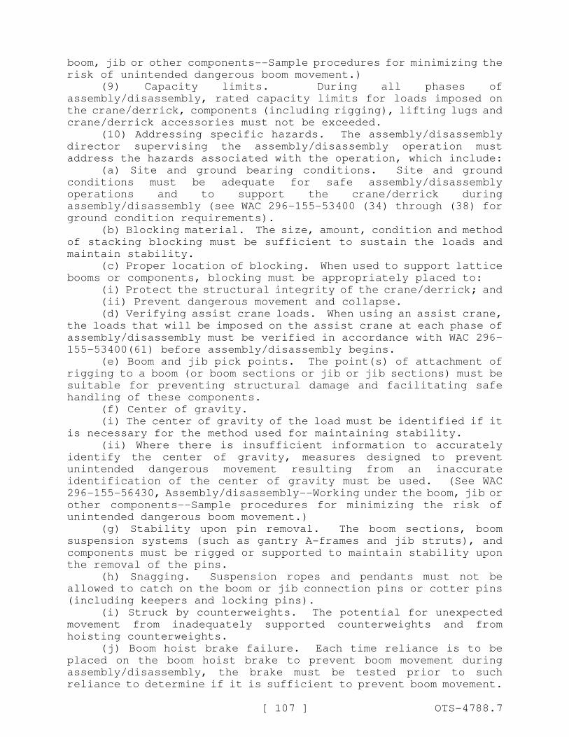
[ 107 ] OTS-4788.7
boom, jib or other components--Sample procedures for minimizing the
risk of unintended dangerous boom movement.)
(9) Capacity limits. During all phases of
assembly/disassembly, rated capacity limits for loads imposed on
the crane/derrick, components (including rigging), lifting lugs and
crane/derrick accessories must not be exceeded.
(10) Addressing specific hazards. The assembly/disassembly
director supervising the assembly/disassembly operation must
address the hazards associated with the operation, which include:
(a) Site and ground bearing conditions. Site and ground
conditions must be adequate for safe assembly/disassembly
operations and to support the crane/derrick during
assembly/disassembly (see WAC 296-155-53400 (34) through (38) for
ground condition requirements).
(b) Blocking material. The size, amount, condition and method
of stacking blocking must be sufficient to sustain the loads and
maintain stability.
(c) Proper location of blocking. When used to support lattice
booms or components, blocking must be appropriately placed to:
(i) Protect the structural integrity of the crane/derrick; and
(ii) Prevent dangerous movement and collapse.
(d) Verifying assist crane loads. When using an assist crane,
the loads that will be imposed on the assist crane at each phase of
assembly/disassembly must be verified in accordance with WAC 296-
155-53400(61) before assembly/disassembly begins.
(e) Boom and jib pick points. The point(s) of attachment of
rigging to a boom (or boom sections or jib or jib sections) must be
suitable for preventing structural damage and facilitating safe
handling of these components.
(f) Center of gravity.
(i) The center of gravity of the load must be identified if it
is necessary for the method used for maintaining stability.
(ii) Where there is insufficient information to accurately
identify the center of gravity, measures designed to prevent
unintended dangerous movement resulting from an inaccurate
identification of the center of gravity must be used. (See WAC
296-155-56430, Assembly/disassembly--Working under the boom, jib or
other components--Sample procedures for minimizing the risk of
unintended dangerous boom movement.)
(g) Stability upon pin removal. The boom sections, boom
suspension systems (such as gantry A-frames and jib struts), and
components must be rigged or supported to maintain stability upon
the removal of the pins.
(h) Snagging. Suspension ropes and pendants must not be
allowed to catch on the boom or jib connection pins or cotter pins
(including keepers and locking pins).
(i) Struck by counterweights. The potential for unexpected
movement from inadequately supported counterweights and from
hoisting counterweights.
(j) Boom hoist brake failure. Each time reliance is to be
placed on the boom hoist brake to prevent boom movement during
assembly/disassembly, the brake must be tested prior to such
reliance to determine if it is sufficient to prevent boom movement.
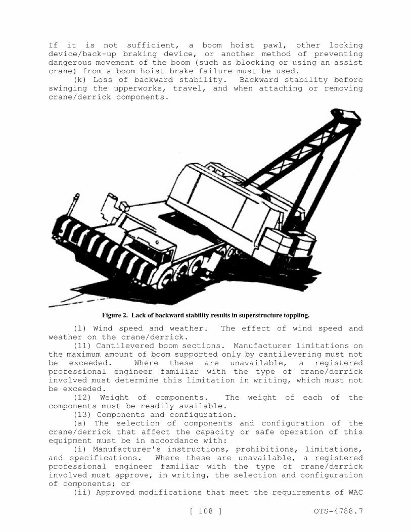
[ 108 ] OTS-4788.7
If it is not sufficient, a boom hoist pawl, other locking
device/back-up braking device, or another method of preventing
dangerous movement of the boom (such as blocking or using an assist
crane) from a boom hoist brake failure must be used.
(k) Loss of backward stability. Backward stability before
swinging the upperworks, travel, and when attaching or removing
crane/derrick components.
Figure 2. Lack of backward stability results in superstructure toppling.
(l) Wind speed and weather. The effect of wind speed and
weather on the crane/derrick.
(11) Cantilevered boom sections. Manufacturer limitations on
the maximum amount of boom supported only by cantilevering must not
be exceeded. Where these are unavailable, a registered
professional engineer familiar with the type of crane/derrick
involved must determine this limitation in writing, which must not
be exceeded.
(12) Weight of components. The weight of each of the
components must be readily available.
(13) Components and configuration.
(a) The selection of components and configuration of the
crane/derrick that affect the capacity or safe operation of this
equipment must be in accordance with:
(i) Manufacturer's instructions, prohibitions, limitations,
and specifications. Where these are unavailable, a registered
professional engineer familiar with the type of crane/derrick
involved must approve, in writing, the selection and configuration
of components; or
(ii) Approved modifications that meet the requirements of WAC
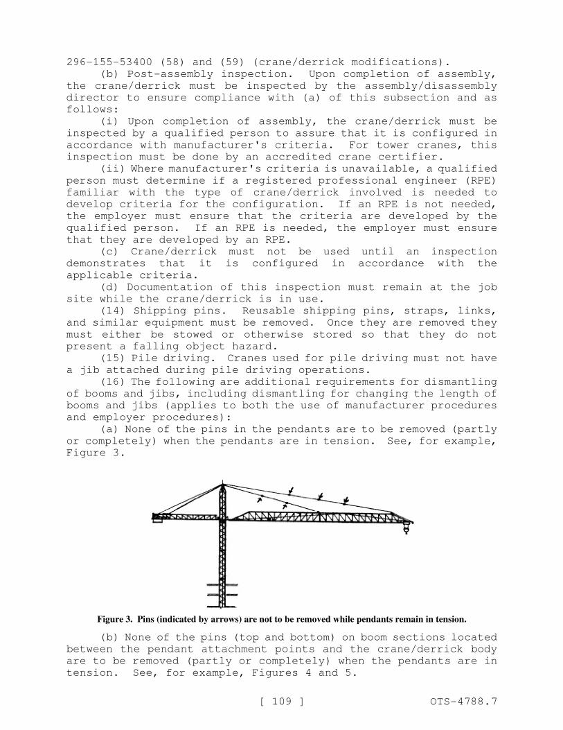
[ 109 ] OTS-4788.7
296-155-53400 (58) and (59) (crane/derrick modifications).
(b) Post-assembly inspection. Upon completion of assembly,
the crane/derrick must be inspected by the assembly/disassembly
director to ensure compliance with (a) of this subsection and as
follows:
(i) Upon completion of assembly, the crane/derrick must be
inspected by a qualified person to assure that it is configured in
accordance with manufacturer's criteria. For tower cranes, this
inspection must be done by an accredited crane certifier.
(ii) Where manufacturer's criteria is unavailable, a qualified
person must determine if a registered professional engineer (RPE)
familiar with the type of crane/derrick involved is needed to
develop criteria for the configuration. If an RPE is not needed,
the employer must ensure that the criteria are developed by the
qualified person. If an RPE is needed, the employer must ensure
that they are developed by an RPE.
(c) Crane/derrick must not be used until an inspection
demonstrates that it is configured in accordance with the
applicable criteria.
(d) Documentation of this inspection must remain at the job
site while the crane/derrick is in use.
(14) Shipping pins. Reusable shipping pins, straps, links,
and similar equipment must be removed. Once they are removed they
must either be stowed or otherwise stored so that they do not
present a falling object hazard.
(15) Pile driving. Cranes used for pile driving must not have
a jib attached during pile driving operations.
(16) The following are additional requirements for dismantling
of booms and jibs, including dismantling for changing the length of
booms and jibs (applies to both the use of manufacturer procedures
and employer procedures):
(a) None of the pins in the pendants are to be removed (partly
or completely) when the pendants are in tension. See, for example,
Figure 3.
Figure 3. Pins (indicated by arrows) are not to be removed while pendants remain in tension.
(b) None of the pins (top and bottom) on boom sections located
between the pendant attachment points and the crane/derrick body
are to be removed (partly or completely) when the pendants are in
tension. See, for example, Figures 4 and 5.
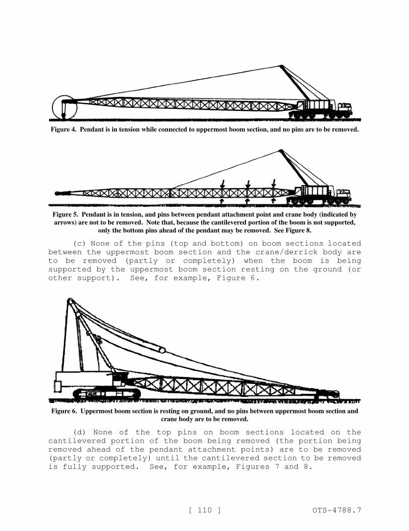
[ 110 ] OTS-4788.7
Figure 4. Pendant is in tension while connected to uppermost boom section, and no pins are to be removed.
Figure 5. Pendant is in tension, and pins between pendant attachment point and crane body (indicated by
arrows) are not to be removed. Note that, because the cantilevered portion of the boom is not supported,
only the bottom pins ahead of the pendant may be removed. See Figure 8.
(c) None of the pins (top and bottom) on boom sections located
between the uppermost boom section and the crane/derrick body are
to be removed (partly or completely) when the boom is being
supported by the uppermost boom section resting on the ground (or
other support). See, for example, Figure 6.
Figure 6. Uppermost boom section is resting on ground, and no pins between uppermost boom section and
crane body are to be removed.
(d) None of the top pins on boom sections located on the
cantilevered portion of the boom being removed (the portion being
removed ahead of the pendant attachment points) are to be removed
(partly or completely) until the cantilevered section to be removed
is fully supported. See, for example, Figures 7 and 8.
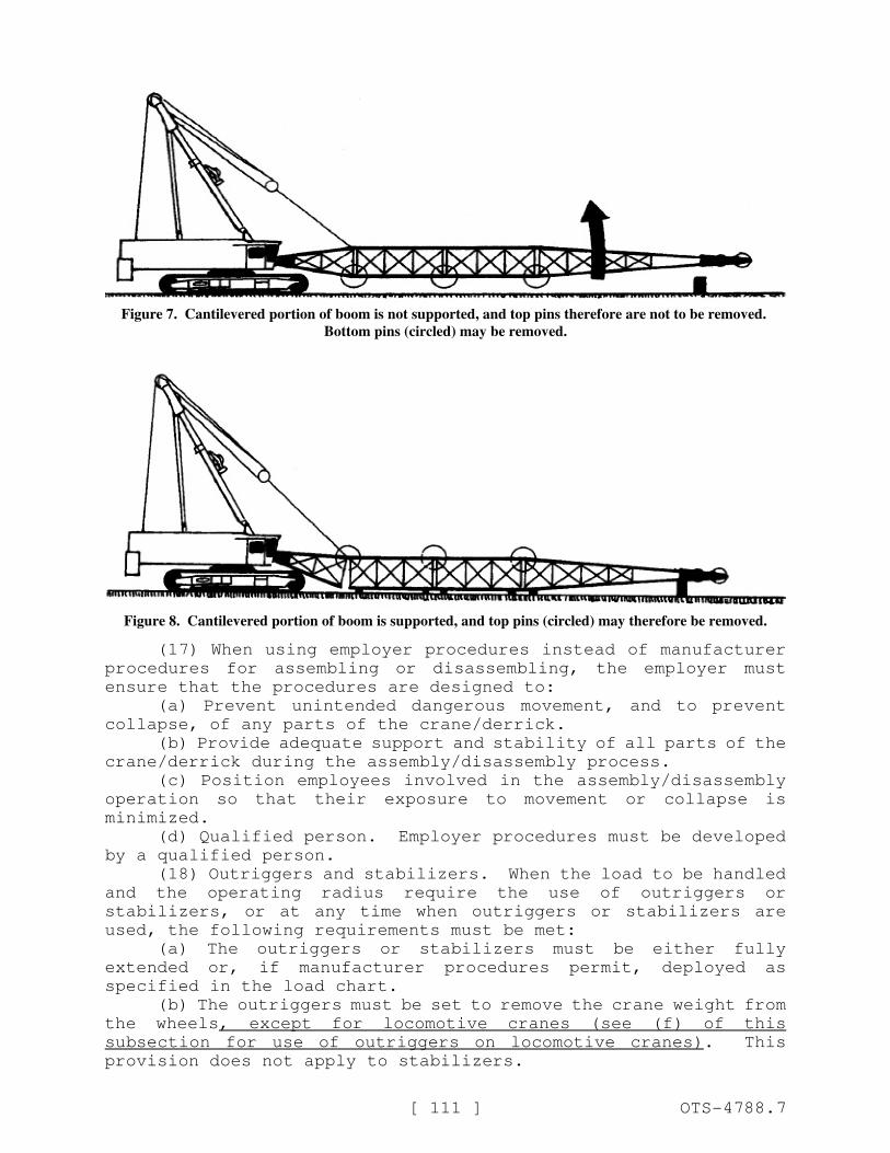
[ 111 ] OTS-4788.7
Figure 7. Cantilevered portion of boom is not supported, and top pins therefore are not to be removed.
Bottom pins (circled) may be removed.
Figure 8. Cantilevered portion of boom is supported, and top pins (circled) may therefore be removed.
(17) When using employer procedures instead of manufacturer
procedures for assembling or disassembling, the employer must
ensure that the procedures are designed to:
(a) Prevent unintended dangerous movement, and to prevent
collapse, of any parts of the crane/derrick.
(b) Provide adequate support and stability of all parts of the
crane/derrick during the assembly/disassembly process.
(c) Position employees involved in the assembly/disassembly
operation so that their exposure to movement or collapse is
minimized.
(d) Qualified person. Employer procedures must be developed
by a qualified person.
(18) Outriggers and stabilizers. When the load to be handled
and the operating radius require the use of outriggers or
stabilizers, or at any time when outriggers or stabilizers are
used, the following requirements must be met:
(a) The outriggers or stabilizers must be either fully
extended or, if manufacturer procedures permit, deployed as
specified in the load chart.
(b) The outriggers must be set to remove the crane weight from
the wheels, except for locomotive cranes (see (f) of this
subsection for use of outriggers on locomotive cranes). This
provision does not apply to stabilizers.

[ 112 ] OTS-4788.7
(c) When outrigger floats are used, they must be attached to
the outriggers. When stabilizer floats are used they must be
attached to the stabilizers.
(d) Each outrigger or stabilizer must be visible to the
operator or to a signal person during extension and setting.
(e) Outrigger and stabilizer blocking must:
(i) Meet the requirements in subsection (((9))) (10)(b) and
(c) of this section.
(ii) Be placed only under the outrigger or stabilizer
float/pad of the jack or, where the outrigger or stabilizer is
designed without a jack, under the outer bearing surface of the
extended outrigger or stabilizer beam.
(f) For locomotive cranes, when using outriggers or
stabilizers to handle loads, the manufacturer's procedures must be
followed. When lifting loads without using outriggers or
stabilizers, the manufacturer's procedures must be met regarding
truck wedges or screws.
(19) Rigging. In addition to the following requirements in
WAC 296-155-556, 296-155-558, 296-155-560 and 296-155-562 and other
requirements in this and other standards applicable to rigging,
when rigging is used for assembly/disassembly, the employer must
ensure that:
(a) The rigging work is done by a qualified rigger. See WAC
296-155-53306.
(b) Synthetic slings are protected from: Abrasive, sharp or
acute edges, and configurations that could cause a reduction of the
sling's rated capacity, such as distortion or localized
compression. See WAC 296-155-55815(6), 296-155-55820(6) and 296-
155-55825(6).
Note: Requirements for the protection of wire rope slings are contained in WAC 296-155-55805.
(c) When synthetic slings are used, the synthetic sling
manufacturer's instructions, limitations, specifications and
recommendations must be followed.
AMENDATORY SECTION (Amending WSR 12-01-086, filed 12/20/11,
effective 2/1/12)
WAC 296-155-53403 Fall protection. (1) Application.(a) Subsections (2), (3)(b), (5) and (6) of this section apply
to all cranes/derricks covered by this part except tower cranes.
(b) Subsections (3)(a), (4), (7), (10) and (11) of this
section apply to all cranes/derricks covered by this part.
(c) Subsections (3)(c) and (9) of this section apply only to
tower cranes.
(2) Boom walkways.
(a) Cranes/derricks manufactured after the effective date of
this section with lattice booms must be equipped with walkways on
the boom(s) if the vertical profile of the boom (from cord
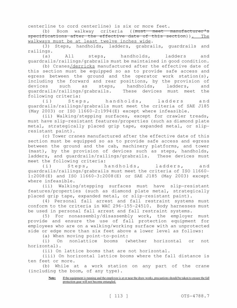
[ 113 ] OTS-4788.7
centerline to cord centerline) is six or more feet.
(b) Boom walkway criteria ((must meet manufacturer's
specifications after the effective date of this section)). The
walkways must be at least twelve inches wide.
(3) Steps, handholds, ladders, grabrails, guardrails and
railings.
(a) All steps, handholds, ladders and
guardrails/railings/grabrails must be maintained in good condition.
(b) Cranes/derricks manufactured after the effective date of
this section must be equipped so as to provide safe access and
egress between the ground and the operator work station(s),
including the forward and rear positions, by the provision of
devices such as steps, handholds, ladders, and
guardrails/railings/grabrails. These devices must meet the
following criteria:
( i ) S t e p s , h a n d h o l d s , l a d d e r s a n d
guardrails/railings/grabrails must meet the criteria of SAE J185
(May 2003) or ISO 11660-2:1994(E) except where infeasible.
(ii) Walking/stepping surfaces, except for crawler treads,
must have slip-resistant features/properties (such as diamond plate
metal, strategically placed grip tape, expanded metal, or slip-
resistant paint).
(c) Tower cranes manufactured after the effective date of this
section must be equipped so as to provide safe access and egress
between the ground and the cab, machinery platforms, and tower
(mast), by the provision of devices such as steps, handholds,
ladders, and guardrails/railings/grabrails. These devices must
meet the following criteria:
( i ) S t e p s , h a n d h o l d s , l a d d e r s , a n d
guardrails/railings/grabrails must meet the criteria of ISO 11660-
1:2008(E) and ISO 11660-3:2008(E) or SAE J185 (May 2003) except
where infeasible.
(ii) Walking/stepping surfaces must have slip-resistant
features/properties (such as diamond plate metal, strategically
placed grip tape, expanded metal, or slip-resistant paint).
(4) Personal fall arrest and fall restraint systems must
conform to the criteria in WAC 296-155-24510. Body harnesses must
be used in personal fall arrest and fall restraint systems.
(5) For nonassembly/disassembly work, the employer must
provide and ensure the use of fall protection equipment for
employees who are on a walking/working surface with an unprotected
side or edge more than six feet above a lower level as follows:
(a) When moving point-to-point:
(i) On nonlattice booms (whether horizontal or not
horizontal).
(ii) On lattice booms that are not horizontal.
(iii) On horizontal lattice booms where the fall distance is
ten feet or more.
(b) While at a work station on any part of the crane
(including the boom, of any type).
Note: If the equipment is running and the employee is at or near the draw-works, precautions should be taken to ensure the fall
protection gear will not become entangled.
[ 114 ] OTS-4788.7
(6) For assembly/disassembly work, the employer must provide
and ensure the use of fall protection equipment for employees who
are on a walking/working surface with an unprotected side or edge
more than ten feet above a lower level.
Note: If the equipment is running and the employee is at or near the draw-works, precautions should be taken to ensure the fall
protection gear will not become entangled.
(7) Anchorage criteria.
(a) Anchorages used for attachment of personal fall arrest
equipment must be independent of any anchorage being used to
support or suspend platforms and capable of supporting at least
five thousand pounds (22.2 kN) per employee attached, or must be
designed, installed, and used as follows:
(i) As part of a complete personal fall arrest system which
maintains a safety factor of at least two; and
(ii) Under the supervision of a qualified person.
(b) Positioning devices must be secured to an anchorage
capable of supporting at least twice the potential impact load of
an employee's fall or three thousand pounds (13.3 kN), whichever is
greater.
(c) Anchorages for personal fall arrest and positioning device
systems.
(i) Personal fall arrest systems must be anchored to any
apparently substantial part of the equipment unless a competent
person, from a visual inspection, without an engineering analysis,
would conclude that the criteria in (a) of this subsection would
not be met.
(ii) Positioning device systems must be anchored to any
apparently substantial part of the crane unless a competent person,
from a visual inspection, without an engineering analysis, would
conclude that the criteria in (b) of this subsection would not be
met.
(iii) Attachable anchor devices (portable anchor devices that
are attached to the crane) must meet the anchorage criteria in (a)
of this subsection for personal fall arrest systems and (b) of this
subsection for positioning device systems.
(8) Anchorages for fall restraint systems. Fall restraint
systems must be anchored to any part of the crane that is capable
of withstanding twice the maximum load that an employee may impose
on it during reasonably anticipated conditions of use.
(9) Tower cranes.
(a) For work other than erecting, climbing, and dismantling,
the employer must provide and ensure the use of fall protection
equipment for employees who are on a walking/working surface with
an unprotected side or edge more than six feet above a lower level.
Note: If the equipment is running and the employee is at or near the draw-works, precautions should be taken to ensure the fall
protection gear will not become entangled.
(b) For erecting, climbing, and dismantling work, the employer
must provide and ensure the use of fall protection equipment for
employees who are on a walking/working surface with an unprotected
side or edge more than ten feet above a lower level.
(10) Anchoring to the load line. A personal fall arrest
system is permitted to be anchored to the crane/derrick's hook (or
[ 115 ] OTS-4788.7
other part of the load line) where all of the following
requirements are met:
(a) A qualified person has determined that the set-up and
rated capacity of the crane/derrick (including the hook, load line
and rigging) meets or exceeds the requirements in subsection (7)(a)
of this section.
(b) The crane operator must be at the worksite and informed
that the crane is being used for this purpose.
(c) No load is suspended from the load line when the personal
fall arrest system is anchored to the crane/derrick's hook (or
other part of the load line).
(11) Training. The employer must train each employee who may
be exposed to fall hazards while on, or hoisted by, cranes/derricks
covered by this section on all of the following:
(a) The requirements in this part that address fall
protection.
(b) The applicable requirements in Parts C-1 and K of this
chapter.
AMENDATORY SECTION (Amending WSR 12-01-086, filed 12/20/11,
effective 2/1/12)
WAC 296-155-53404 Wire rope. (1) Selection and installationcriteria.
(a) Original crane/derrick wire rope and replacement wire rope
must be selected and installed in accordance with the requirements
of this section. Selection of replacement wire rope must be in
accordance with the recommendations of the wire rope manufacturer,
the crane/derrick manufacturer, or a qualified person.
(b) Wire rope design criteria: Wire rope (other than rotation
resistant rope) must comply with either Option (1) or Option (2) of
this section, as follows:
(i) Option (1). Wire rope must comply with Section 5-1.7.1 of
ASME B30.5-2007 except that section's paragraph (c) must not apply.
(ii) Option (2). Wire rope must be designed to have, in
relation to the crane's/derrick's rated capacity, a sufficient
minimum breaking force and design factor so that compliance with
the applicable inspection provisions in this section will be an
effective means of preventing sudden rope failure.
(c) Wire rope must be compatible with the safe functioning of
the crane/derrick.
(d) Boom hoist reeving.
(i) Fiber core ropes must not be used for boom hoist or
luffing attachment reeving, except for derricks.
(ii) Rotation resistant ropes must be used for boom hoist
reeving only where the requirements of (e) of this subsection are
met.
(e) Rotation resistant ropes.
(i) Definitions.
[ 116 ] OTS-4788.7
(A) Type I rotation resistant wire rope (Type I). Type I
rotation resistant rope is stranded rope constructed to have little
or no tendency to rotate or, if guided, transmits little or no
torque. It has at least fifteen outer strands and comprises an
assembly of at least three layers of strands laid helically over a
center in two operations. The direction of lay of the outer
strands is opposite to that of the underlying layer.
(B) Type II rotation resistant wire rope (Type II). Type II
rotation resistant rope is stranded rope constructed to have
resistance to rotation. It has at least ten outer strands and
comprises an assembly of two or more layers of strands laid
helically over a center in two or three operations. The direction
of lay of the outer strands is opposite to that of the underlying
layer.
(C) Type III rotation resistant wire rope (Type III). Type
III rotation resistant rope is stranded rope constructed to have
limited resistance to rotation. It has no more than nine outer
strands, and comprises an assembly of two layers of strands laid
helically over a center in two operations. The direction of lay of
the outer strands is opposite to that of the underlying layer.
(ii) Requirements.
(A) Types II and III with an operation design factor of less
than five must not be used for duty cycle or repetitive lifts.
(B) Rotation resistant ropes (including Types I, II and III)
must have an operating design factor of no less than 3.5.
(C) Type I must have an operating design factor of no less
than five, except where the wire rope manufacturer and the
crane/derrick manufacturer approves the design factor, in writing.
(D) Types II and III must have an operating design factor of
no less than five, except where the requirements of (e)(iii) of
this subsection are met.
(iii) When Types II and III with an operation design factor of
less than five are used (for nonduty cycle, nonrepetitive lifts),
the following requirements must be met for each lifting operation:
(A) A qualified person must inspect the rope in accordance
with subsection (2)(a) of this section. The rope must be used only
if the qualified person determines that there are no deficiencies
constituting a hazard. In making this determination, more than one
broken wire in any one rope lay must be considered a hazard.
(B) Operations must be conducted in such a manner and at such
speeds as to minimize dynamic effects.
(C) Each lift made under these provisions must be recorded in
the monthly and annual inspection documents. Such prior uses must
be considered by the qualified person in determining whether to use
the rope again.
(iv) Additional requirements for rotation resistant ropes for
boom hoist reeving.
(A) Rotation resistant ropes must not be used for boom hoist
reeving, except where the requirements of (e)(iv)(B) of this
subsection are met.
(B) Rotation resistant ropes may be used as boom hoist reeving
when load hoists are used as boom hoists for attachments such as
luffing attachments or boom and mast attachment systems. Under
[ 117 ] OTS-4788.7
these conditions, all of the following requirements must be met:
(I) The drum must provide a first layer rope pitch diameter of
not less than eighteen times the nominal diameter of the rope used.
(II) The requirements in WAC 296-155-53400(44) (irrespective
of the date of manufacture of the crane/derrick), and WAC 296-155-
53400(45).
(III) The requirements of ANSI/ASME B30.5-2007, Section 5-
1.3.2(a), (a)(2) through (a)(4), (b) and (d), except that the
minimum pitch diameter for sheaves used in multiple rope reeving is
eighteen times the nominal diameter of the rope used instead of the
value of sixteen specified in Section 5-1.3.2(d).
(IV) All sheaves used in the boom hoist reeving system must
have a rope pitch diameter of not less than eighteen times the
nominal diameter of the rope used.
(V) The operating design factor for the boom hoist reeving
system must be not less than five.
(VI) The operating design factor for these ropes must be the
total minimum breaking force of all parts of rope in the system
divided by the load imposed on the rope system when supporting the
static weights of the structure and the load within the
crane's/derrick's rated capacity.
(VII) When provided, a power-controlled lowering system must
be capable of handling rated capacities and speeds as specified by
the manufacturer.
(f) Wire rope clips used in conjunction with wedge sockets
must be attached to the unloaded dead end of the rope only, except
that the use of devices specifically designed for dead-ending rope
in a wedge socket is permitted.
(g) Socketing must be done in the manner specified by the
manufacturer of the wire rope or fitting.
(h) Prior to cutting a wire rope, seizings must be placed on
each side of the point to be cut. The length and number of
seizings must be in accordance with the wire rope manufacturer's
instructions.
(2) Inspection of wire ropes.
(a) Shift inspection.
(i) A competent person must begin a visual inspection prior to
each shift the crane/derrick is used, which must be completed
before or during that shift. The inspection must consist of
observation of accessible wire ropes (running and standing) that
are likely to be in use during the shift for apparent deficiencies,
including those listed in (a)(ii) of this subsection. Untwisting
(opening) of wire rope or booming down is not required as part of
this inspection.
(A) Category I. Apparent deficiencies in this category
include the following:
(I) Distortion of the wire rope structure such as kinking,
crushing, unstranding, birdcaging, signs of core failure or steel
core protrusion between the outer strands.
(II) Corrosion.
(III) Electric arc damage (from a source other than power
lines) or heat damage.
(IV) Improperly applied end connections.
[ 118 ] OTS-4788.7
(V) Corroded, cracked, bent, or worn end connections (such as
from severe service).
(B) Category II. Apparent deficiencies in this category are:
(I) Visibly broken wires in running wire ropes: Six randomly
distributed broken wires in one rope lay or three broken wires in
one strand in one rope lay, where a rope lay is the length along
the rope in which one strand makes a complete revolution around the
rope;
(II) Visibly broken wires in rotation resistant ropes: Two
randomly distributed broken wires in six rope diameters or four
randomly distributed broken wires in thirty rope diameters;
(III) Visibly broken wires in pendants or standing wire ropes:
More than two broken wires in one rope lay located in rope beyond
end connections and/or more than one broken wire at an end
connection; and
(IV) A diameter reduction of more than five percent from
nominal diameter.
(C) Category III. Apparent deficiencies in this category
include the following:
(I) In rotation resistant wire rope, core protrusion or other
distortion indicating core failure.
(II) Prior electrical contact with a power line.
(III) A broken strand.
(ii) Critical review items. The competent person must give
particular attention to all of the following:
(A) Rotation resistant wire rope in use.
(B) Wire rope being used for boom hoists and luffing hoists,
particularly at reverse bends.
(C) Wire rope at flange points, crossover points and
repetitive pickup points on drums.
(D) Wire rope at or near terminal ends.
(E) Wire rope in contact with saddles, equalizer sheaves or
other sheaves where rope travel is limited.
(iii) Removal from service.
(A) If a deficiency in Category I is identified, an immediate
determination must be made by the competent person as to whether
the deficiency constitutes a safety hazard. If the deficiency is
determined to constitute a safety hazard, operations involving use
of the wire rope in question must be prohibited until:
(I) The wire rope is replaced; or
(II) If the deficiency is localized, the problem is corrected
by removing the damaged section of the wire rope; the undamaged
portion may continue to be used. Joining lengths of wire rope by
splicing is prohibited. If a rope is shortened under this
subsection, the employer must ensure that the drum will still have
two wraps of wire when the load and/or boom is in its lowest
position.
(B) If a deficiency in Category II is identified, operations
involving use of the wire rope in question must be prohibited
until:
(I) The employer complies with the wire rope manufacturer's
established criterion for removal from service or a different
criterion that the wire rope manufacturer has approved in writing
[ 119 ] OTS-4788.7
for that specific wire rope;
(II) The wire rope is replaced.
(C) If the deficiency is localized, the problem is corrected
by severing the wire rope in two; the undamaged portion may
continue to be used. Joining lengths of wire rope by splicing is
prohibited. If a rope is shortened under this subsection, the
employer must ensure that the drum will still have two wraps of
wire when the load and/or boom is in its lowest position. If a
deficiency in category III is identified, operations involving use
of the wire rope in question must be prohibited until:
(I) The wire rope is replaced; or
(II) If the deficiency (other than power line contact) is
localized, the problem is corrected by severing the wire rope in
two; the undamaged portion may continue to be used. Joining
lengths of wire rope by splicing is prohibited. Repair of wire
rope that contacted an energized power line is also prohibited. If
a rope is shortened under this subsection, the employer must ensure
that the drum will still have two wraps of wire when the load
and/or boom is in its lowest position.
(D) Where a wire rope is required to be removed from service
under this section, either the crane/derrick (as a whole) or the
hoist with that wire rope must be tagged-out, in accordance with
WAC 296-155-53400(67), until the wire rope is repaired or replaced.
(b) Monthly inspection.
(i) Each month an inspection must be conducted in accordance
with (a) of this subsection (shift inspection).
(ii) The inspection must include any deficiencies that the
qualified person who conducts the annual inspection determines
under (c)(iii) of this subsection must be monitored.
(iii) Wire ropes on a crane/derrick must not be used until an
inspection under this subsection demonstrates that no corrective
action under (a)(iii) of this subsection is required.
(iv) This inspection must be documented and be kept and made
available upon request. Electronic records are acceptable.
(c) Annual/comprehensive, for cranes and derricks not covered
by WAC ((296-155-529)) 296-155-531 through 296-155-53214.
(i) At least every twelve months, wire ropes in use on the
crane/derrick must be inspected by a qualified person in accordance
with (a) of this subsection (shift inspection).
(ii) In addition, at least every twelve months, the wire ropes
in use on the crane/derrick must be inspected by a qualified
person, as follows:
(A) The inspection must be for deficiencies of the types
listed in (a)(i)(B) of this subsection.
(B) The inspection must be complete and thorough, covering the
surface of the entire length of the wire ropes, with particular
attention given to all of the following:
(I) Critical review items listed in (a)(ii) of this
subsection.
(II) Those sections that are normally hidden during shift and
monthly inspections.
(III) Wire rope in contact with saddles, equalizer sheaves or
other sheaves where rope travel is limited.
[ 120 ] OTS-4788.7
(IV) Wire rope subject to reverse bends.
(V) Wire rope passing over sheaves.
(VI) Wire rope at or near terminal ends.
(C) Exception: In the event an inspection under (c)(ii) of
this subsection is not feasible due to existing set-up and
configuration of the crane/derrick (such as where an assist crane
is needed) or due to site conditions (such as a dense urban
setting). The inspection must consist of observation of the
working range plus three additional wraps (running and standing)
prior to use.
(iii) If a deficiency is identified, an immediate
determination must be made by the qualified person as to whether
the deficiency constitutes a safety hazard.
(A) If the deficiency is determined to constitute a safety
hazard, operations involving the use of the wire rope in question
is prohibited until:
(I) The wire rope is replaced; or
(II) If the deficiency is localized, the problem is corrected
by severing the wire rope in two; the undamaged portion may
continue to be used. Joining lengths of wire rope by splicing is
prohibited. If a rope is shortened under this subsection, the
employer must ensure that the drum will still have two wraps of
wire when the load and/or boom is in its lowest position.
(B) If the qualified person determines that, though not
presently a safety hazard, the deficiency needs to be monitored,
the employer must ensure that the deficiency is checked in the
monthly inspections.
(iv) This inspection must be documented and be kept and made
available upon request. Electronic records are acceptable.
(d) Rope lubricants that are of the type that hinder
inspection must not be used.
(3) All documents produced under this section must be
available, during the applicable document retention period, to all
persons who conduct inspections under this section.
AMENDATORY SECTION (Amending WSR 12-01-086, filed 12/20/11,
effective 2/1/12)
WAC 296-155-53406 Signals. (1) A qualified signal personthat meets the requirements in WAC 296-155-53302 must be provided
in each of the following situations:
(a) The point of operation, meaning the load travel or the
area near or at load placement, is not in full view of the
crane/derrick operator.
(b) When the crane is traveling, the view in the direction of
travel is obstructed.
(c) Due to site specific safety concerns, either the
crane/derrick operator or the person handling the load determines
that it is necessary.
[ 121 ] OTS-4788.7
(2) Types of signals. Signals to crane/derrick operators must
be by hand, voice, audible, or other means at least as effective.
(3) Hand signals.
(a) When using hand signals, the standard method as
established in the applicable ASME B30 standards must be used.
Where use of the standard method for hand signals is infeasible, or
where an operation or use of an attachment is not covered in the
standard method, nonstandard hand signals may be used in accordance
with (b) of this subsection.
Note: See WAC 296-155-56400 for the hand signal chart.
(b) Nonstandard hand signals. When using nonstandard hand
signals, the signal person, operator, and lift director must
contact each other prior to the operation and agree on the
nonstandard hand signals that will be used.
(4) Signals other than hand, voice or audible signals may be
used where the employer demonstrates that the signals provided are
at least equally effective communications as voice, audible, or
standard method hand signals.
(5) Use and suitability.
(a) Prior to beginning operations, the operator, signal
person, and lift director, must contact each other and agree on the
voice signals that will be used. Once the voice signals are agreed
upon, these employees need not meet again to discuss voice signals
unless another employee is added or substituted, there is confusion
about the voice signals, or a voice signal is to be changed.
(b) Each voice signal must contain the following three
elements, given in the following order: Function (such as hoist,
boom, etc.) and direction; distance and/or speed; function stop.
(c) The operator, signal person and lift director, must be
able to effectively communicate in the language used.
(d) The signals used (hand, voice, audible, or other effective
means), and means of transmitting the signals to the operator (such
as direct line of sight, video, radio, etc.) must be appropriate
for the site conditions.
(e) Signals must be discernible or audible at all times. The
crane operator must not respond unless signals are clearly
understood.
(6) During operations requiring signals, the ability to
transmit signals between the operator and signal person must be
maintained. If that ability is interrupted at any time, the
operator must safely stop operations requiring signals until it is
reestablished and a proper signal is given and understood.
(7) If the operator becomes aware of a safety problem and
needs to communicate with the signal person, the operator must
safely stop operations. Operations must not resume until the
operator and signal person agree that the problem has been
resolved.
(8) Only one person gives signals to a crane/derrick at a
time, except in circumstances covered by subsection (9) of this
section.
(9) Anyone who becomes aware of a safety problem must alert
the operator or signal person by giving the stop or emergency stop
[ 122 ] OTS-4788.7
signal. The operator must obey a stop (or emergency stop) signal,
irrespective of who gives it.
(10) All directions given to the operator by the signal person
must be given from the operator's direction perspective.
(11) Communication with multiple cranes/derricks. Where a
signal person(s) is in communication with more than one
crane/derrick, a system for identifying the crane/derrick for which
each signal is intended must be used, as follows:
(a) For each signal, prior to giving the function/direction,
the signal person must identify the crane/derrick for which the
signal is intended; or
(b) An equally effective method of identifying which
crane/derrick the signal is intended for must be used.
(12) Hand signal chart. Hand signal charts must be either
posted on the crane/derrick or conspicuously posted in the vicinity
of the hoisting operations.
(13) Radio, telephone or other electronic transmission of
signals.
(a) The device(s) used to transmit signals must be tested on
site before beginning operations to ensure that the signal
transmission is effective, clear, and reliable.
(b) Signal transmission must be through a dedicated channel
except:
(i) Multiple cranes/derricks and one or more signal persons
may share a dedicated channel for the purpose of coordinating
operations.
(ii) Where a crane is being operated on or adjacent to
railroad tracks, and the actions of the crane operator need to be
coordinated with the movement of other equipment or trains on the
same or adjacent tracks.
(c) The operator's reception of signals must be made by a
hands-free system.
AMENDATORY SECTION (Amending WSR 12-01-086, filed 12/20/11,
effective 2/1/12)
WAC 296-155-53408 Power line safety. (1) Assembly and
disassembly of crane/derrick.
(a) Before assembling or disassembling crane/derrick, the
employer must determine if any part of the crane/derrick, load line
or load (including rigging and lifting accessories) could get, in
the direction or area of assembly, closer than twenty feet of a
power line that is up to 350 kV or closer than fifty feet of a
power line that exceeds 350 kV during the assembly/disassembly
process. If so, the employer must meet the requirements in Option
(1), Option (2), or Option (3), as follows:
(i) Option (1) - Deenergize and ground. Confirm from the
utility owner/operator that the power line has been deenergized and
visibly grounded at the worksite.
[ 123 ] OTS-4788.7
(ii) Option (2) - Clearance. Ensure that no part of the
crane/derrick, load line or load (including rigging and lifting
accessories), gets closer than twenty feet of a power line that is
up to 350 kV or closer than fifty feet of a power line that exceeds
350 kV by implementing the measures specified in (b) of this
subsection.
(iii) Option (3) - Table 4 clearance.
(A) Determine the line's voltage and the minimum approach
distance permitted under Table 4 of this section.
(B) Determine if any part of the crane/derrick, load line or
load (including rigging and lifting accessories), could get closer
than the minimum approach distance of the power line permitted
under Table 4 of this section. If so, then the employer must
follow the requirements in (b) of this subsection to ensure that no
part of the crane/derrick, load line, or load (including rigging
and lifting accessories), gets closer to the line than the minimum
approach distance.
(b) Preventing encroachment/electrocution. Where encroachment
precautions are required under Option (2), or Option (3), all of
the following requirements must be met:
(i) Conduct a planning meeting with the assembly/disassembly
director, operator, assembly/disassembly crew and the other workers
who will be in the assembly/disassembly area to review the location
of the power line(s) and the steps that will be implemented to
prevent encroachment/electrocution.
(ii) If tag lines are used, they must be nonconductive.
(iii) At least one of the following additional measures must
be in place. The measure selected from this list must be effective
in preventing encroachment. The additional measures are:
(A) Use a dedicated spotter who is in continuous contact with
the crane/derrick operator, plus an elevated warning line,
barricade, or line of signs, in view of the spotter, equipped with
flags or similar high-visibility markings. The dedicated spotter
must:
(I) Be equipped with a visual aid to assist in identifying the
minimum clearance distance. Examples of a visual aid include: A
clearly visible line painted on the ground; a clearly visible line
on stanchions; a set of clearly visible line-of-sight landmarks
(such as a fence post behind the dedicated spotter and a building
corner ahead of the dedicated spotter).
(II) Be positioned to effectively gauge the clearance
distance.
(III) Where necessary, use equipment that enables the
dedicated spotter to communicate directly with the operator, in
accordance with WAC 296-155-53406(13) (radio, telephone, or other
electronic transmission of signals).
(IV) Give timely information to the operator so that the
required clearance distance can be maintained.
Note: To be considered a dedicated spotter, the requirements of WAC 296-155-53302 (Signal person qualifications) must be
met and his/her sole responsibility is to watch the separation between the power line and the equipment, the load line
and load (including rigging and lifting accessories), and ensure through communication with the operator that the
applicable minimum approach distance is not breached.
(B) A proximity alarm set to give the operator sufficient
[ 124 ] OTS-4788.7
warning to prevent encroachment.
(C) A device that automatically warns the operator when to
stop movement, such as a range control warning device. Such a
device must be set to give the operator sufficient warning to
prevent encroachment.
(D) A device that automatically limits range of movement, set
to prevent encroachment.
(c) Assembly/disassembly below power lines is prohibited. No
part of a crane/derrick, load line or load (including rigging and
lifting accessories), whether partially or fully assembled, is
allowed below a power line unless the employer has confirmed that
the utility owner/operator has deenergized and (at the worksite)
visibly grounded the power line.
(d) Assembly/disassembly inside Table 4 clearance is
prohibited. No part of a crane/derrick, load line or load
(including rigging and lifting accessories), whether partially or
fully assembled, is allowed closer than the minimum approach
distance under Table 4 of a power line unless the employer has
confirmed that the utility owner/operator has deenergized and (at
the worksite) visibly grounded the power line.
(e) Voltage information. Where Option (3) is used, the
utility owner/operator of power lines must provide the requested
voltage information prior to commencement of work or within two
working days of the employer's request.
(f) Power lines presumed energized. The employer must assume
that all power lines are energized unless the utility
owner/operator confirms that the power line has been and continues
to be deenergized and visibly grounded at the worksite.
(g) Posting of electrocution warnings. There must be at least
one electrocution hazard warning conspicuously posted in the cab so
that it is in view of the operator and (except for overhead gantry
and tower cranes) at least two on the outside of the crane/derrick.
(2) Operation of crane/derrick.
(a) Hazard assessments and precautions inside the work zone.
Before beginning crane/derrick operations, the employer must:
(i) Identify the work zone.
(A) Define a work zone by demarcating boundaries (such as with
flags, or a device such as a range limit device or range control
warning device) and prohibiting the operator from operating the
crane/derrick past those boundaries; or
(B) Define the work zone as the area three hundred sixty
degrees around the crane/derrick, up to its maximum working radius.
(ii) Determine if any part of the crane/derrick, load line or
load (including rigging and lifting accessories), if operated up to
its maximum working radius in the work zone, could get closer than
twenty feet of a power line that is up to 350 kV or closer than
fifty feet of a power line that exceeds 350 kV. If so, the
employer must meet the requirements in Option (1), Option (2), or
Option (3) as follows:
(A) Option (1) - Deenergize and ground. Confirm from the
utility owner/operator that the power line has been deenergized and
visibly grounded at the worksite.
(B) Option (2) - Twenty-foot clearance. Ensure that no part
[ 125 ] OTS-4788.7
of the crane/derrick, load line, or load (including rigging and
lifting accessories), gets closer than twenty feet to the power
line by implementing the measures specified in (b) of this
subsection.
(C) Option (3) - Table 4 clearance.
(I) Determine the line's voltage and the minimum approach
distance permitted under Table 4 of this section.
(II) Determine if any part of the crane/derrick, load line or
load (including rigging and lifting accessories), while operating
up to its maximum working radius in the work zone, could get closer
than the minimum approach distance of the power line permitted
under Table 4 of this section. If so, then the employer must
follow the requirements in (b) of this subsection to ensure that no
part of the crane/derrick, load line, or load (including rigging
and lifting accessories), gets closer to the line than the minimum
approach distance.
(b) Preventing encroachment/electrocution. Where encroachment
precautions are required under Option (2) or Option (3), all of the
following requirements must be met:
(i) Conduct a planning meeting with the operator and the other
workers who will be in the area of the crane/derrick or load to
review the location of the power line(s), and the steps that will
be implemented to prevent encroachment/electrocution.
(ii) If tag lines are used, they must be nonconductive.
(iii) Erect and maintain an elevated warning line, barricade,
or line of signs, in view of the operator, equipped with flags or
similar high-visibility markings, at twenty feet from a power line
that is up to 350 kV or fifty feet from a power line that exceeds
350 kV (if using Option (2)) or at the minimum approach distance
under Table 4 of this section (if using Option (3)). If the
operator is unable to see the elevated warning line, a dedicated
spotter must be used as described in (iv)(B) of this subsection in
addition to implementing one of the measures described in (b)(i),
(iii) through (v) of this subsection.
(iv) Implement at least one of the following measures:
(A) A proximity alarm set to give the operator sufficient
warning to prevent encroachment.
(B) Use a dedicated spotter who is in continuous contact with
the crane/derrick operator, plus an elevated warning line,
barricade, or line of signs, in view of the spotter, equipped with
flags or similar high-visibility markings. The dedicated spotter
must:
(I) Be equipped with a visual aid to assist in identifying the
minimum clearance distance. Examples of a visual aid include: A
clearly visible line painted on the ground; a clearly visible line
on stanchions; a set of clearly visible line-of-sight landmarks
(such as a fence post behind the dedicated spotter and a building
corner ahead of the dedicated spotter).
(II) Be positioned to effectively gauge the clearance
distance.
(III) Where necessary, use equipment that enables the
dedicated spotter to communicate directly with the operator.
(IV) Give timely information to the operator so that the
[ 126 ] OTS-4788.7
required clearance distance can be maintained.
Note: To be considered a dedicated spotter, the requirements of WAC 296-155-53302 (Signal person qualifications) must be
met and his/her sole responsibility is to watch the separation between the power line and the equipment, the load line
and load (including rigging and lifting accessories), and ensure through communication with the operator that the
applicable minimum approach distance is not breached.
(C) A device that automatically warns the operator when to
stop movement, such as a range control warning device. Such a
device must be set to give the operator sufficient warning to
prevent encroachment.
(D) A device that automatically limits range of movement, set
to prevent encroachment.
(E) An insulating link/device, as defined in WAC 296-155-
52902, installed at a point between the end of the load line (or
below) and the load.
(v) The requirements of (b)(iv) of this subsection do not
apply to work covered by chapter 296-45 WAC.
(c) Voltage information. Where Option (3) is used, the
utility owner/operator of power lines must provide the requested
voltage information prior to commencement of work or within two
working days of the employer's request.
(d) Operations below power lines.
(i) No part of the crane/derrick, load line or load (including
rigging and lifting accessories) is allowed below a power line
unless the employer has confirmed that the utility owner/operator
has deenergized and (at the worksite) visibly grounded the power
line, except where one of the exceptions in (d)(ii) of this
subsection apply.
(ii) Exceptions. (d)(i) of this subsection is inapplicable
where the employer demonstrates that one of the following applies:
(A) The work is covered by chapter 296-45 WAC.
(B) For cranes/derricks with nonextensible booms: The
uppermost part of the crane/derrick, with the boom at true
vertical, would be more than twenty feet below the plane of a power
line that is up to 350 kV, fifty feet below the plane of a power
line that exceeds 350 kV or more than the Table 4 minimum clearance
distance below the plane of the power line.
(C) For cranes with articulating or extensible booms: The
uppermost part of the crane, with the boom in the fully extended
position, at true vertical, would be more than twenty feet below
the plane of a power line that is up to 350 kV, fifty feet below
the plane of a power line that exceeds 350 kV or more than the
Table 4 minimum clearance distance below the plane of the power
line.
(D) The employer demonstrates that compliance with (d)(i) of
this subsection is infeasible and meets the requirements of
subsection (((3))) (4) of this section.
(e) Power lines presumed energized. The employer must assume
that all power lines are energized unless the utility
owner/operator confirms that the power line has been and continues
to be deenergized and visibly grounded at the worksite.
(f) Training.
(i) The employer must train each operator and crew member
assigned to work with the crane/derrick on all the following:
[ 127 ] OTS-4788.7
(A) The procedures to be followed in the event of electrical
contact with a power line. Such training must include:
(I) Information regarding the danger of electrocution from the
operator simultaneously touching the crane/derrick and the ground.
(II) The importance to the operator's safety of remaining
inside the cab except where there is an imminent danger of fire,
explosion, or other emergency that necessitates leaving the cab.
(III) The safest means of evacuating from the crane/derrick
that may be energized.
(IV) The danger of the potentially energized zone around the
crane/derrick (step potential).
(V) The need for crew in the area to avoid approaching or
touching the crane/derrick and the load.
(VI) Safe clearance distance from power lines.
(B) Power lines are presumed to be energized unless the
utility owner/operator confirms that the power line has been and
continues to be deenergized, and visibly grounded at the worksite.
(C) Power lines are presumed to be uninsulated unless the
utility owner/operator or a registered engineer who is a qualified
person with respect to electrical power transmission and
distribution confirms that a power line is insulated.
(D) The limitations of an insulating link/device, proximity
alarm, and range control (and similar) device, if used.
(E) The procedures to be followed to properly ground equipment
and the limitations of grounding.
(ii) Employees working as dedicated spotters must be trained
to enable them to effectively perform their task, including
training on the applicable requirements of this section.
(iii) Training under this section must be administered in
accordance with WAC 296-155-53409(2).
(g) Devices originally designed by the manufacturer for use
as: A safety device (see WAC 296-155-53410), operational aid (see
WAC 296-155-53412), or a means to prevent power line contact or
electrocution, when used to comply with this section, must meet the
manufacturer's procedures for use and conditions of use.
(3) Prior to working near a transmitter/communication tower
where an electrical charge can be induced in the crane/derrick or
materials being handled, the transmitter must be deenergized or the
following precautions must be taken:
(a) The crane/derrick must be provided with an electrical
ground directly to the crane/derrick frame;
(b) Ground jumper cables must be attached to materials being
handled by boom equipment when electrical charge is induced while
working near energized transmitters. Crews must be provided with
nonconductive poles having large alligator clips or other similar
protection to attach the ground cable to the load;
(c) Combustible and flammable materials must be removed from
the immediate area prior to operations; and
(d) If tag lines are used, they must be nonconductive.
(4) Operation of the crane/derrick inside the Table 4 zone.
Operations in which any part of the crane/derrick, load line or
load (including rigging and lifting accessories) is either closer
than the minimum approach distance under Table 4 of an energized
[ 128 ] OTS-4788.7
power line or the power line voltage is undetermined and the
crane/derrick load line or load is within twenty feet from the
power line is prohibited, except where the employer demonstrates
that all of the following requirements are met:
(a) Notify the crane safety program within the department of
labor and industries.
(b) The employer determines that it is infeasible to do the
work without breaching the minimum approach distance under Table 4
of this section.
(c) The employer determines that, after consultation with the
utility owner/operator, it is infeasible to deenergize and ground
the power line or relocate the power line.
(d) Minimum clearance distance.
(i) The power line owner/operator or registered professional
engineer who is a qualified person with respect to electrical power
transmission and distribution determines the minimum clearance
distance that must be maintained to prevent electrical contact in
light of the on-site conditions. The factors that must be
considered in making this determination include, but are not
limited to: Conditions affecting atmospheric conductivity; time
necessary to bring the crane/derrick, load line and load (including
rigging and lifting accessories) to a complete stop; wind
conditions; degree of sway in the power line; lighting conditions,
and other conditions affecting the ability to prevent electrical
contact.
(ii) Subsection (4)(d)(i) of this section does not apply to
work covered by chapter 296-45 WAC; instead, for such work, the
minimum clearance distances specified in chapter 296-45 WAC, Table
1 apply. Employers covered by chapter 296-45 WAC are permitted to
work closer than the distances in chapter 296-45 WAC, Table 1,
where both the requirements of this rule and WAC 296-45-375(10) are
met.
(e) A planning meeting with the employer and utility
owner/operator (or registered professional engineer who is a
qualified person with respect to electrical power transmission and
distribution) is held to determine the procedures that will be
followed to prevent electrical contact and electrocution. At a
minimum these procedures must include:
(i) If the power line is equipped with a device that
automatically reenergizes the circuit in the event of a power line
contact, before the work begins, the automatic reclosing feature of
the circuit interrupting device must be made inoperative if the
design of the device permits.
(ii) A dedicated spotter who is in continuous contact with the
operator. The dedicated spotter must:
(A) Be equipped with a visual aid to assist in identifying the
minimum clearance distance. Examples of a visual aid include, but
are not limited to: A clearly visible line painted on the ground;
a clearly visible line on stanchions; a set of clearly visible
line-of-sight landmarks (such as a fence post behind the dedicated
spotter and a building corner ahead of the dedicated spotter).
(B) Be positioned to effectively gauge the clearance distance.
(C) Where necessary, use equipment that enables the dedicated
[ 129 ] OTS-4788.7
spotter to communicate directly with the operator.
(D) Give timely information to the operator so that the
required clearance distance can be maintained.
Note: To be considered a dedicated spotter, the requirements of WAC 296-155-53302 (Signal person qualifications) must be
met and his/her sole responsibility is to watch the separation between the power line and the equipment, the load line
and load (including rigging and lifting accessories), and ensure through communication with the operator that the
applicable minimum approach distance is not breached.
(iii) An elevated warning line, or barricade (not attached to
the crane), in view of the operator (either directly or through
video equipment), equipped with flags or similar high-visibility
markings, to prevent electrical contact. However, this provision
does not apply to work covered by chapter 296-45 WAC.
(iv) Insulating link/device.
(A) An insulating link/device installed at a point between the
end of the load line (or below) and the load.
(B) For work covered by chapter 296-45 WAC, the requirement in
(e)(iv)(A) of this subsection applies only when working inside the
clearance distances of Table 1 in chapter 296-45 WAC.
(C) For work covered by chapter 296-45 WAC, electrical
workers, involving operations where use of an insulating
link/device is infeasible, the requirements of WAC 296-45-375
(10)(c)(ii) or (iii) may be substituted for the requirement in
(e)(iv)(A) of this subsection.
(v) Until one year after the effective date of this part, the
following procedure may be substituted for the requirement in
(e)(iv)(A) of this subsection: All employees, excluding equipment
operators located on the equipment, who may come in contact with
the equipment, the load line, or the load must be insulated or
guarded from the equipment, the load line, and the load.
Insulating gloves rated for the voltage involved are adequate
insulation for the purposes of this section.
(vi) Until three years after the effective date of this part
the following procedure may be substituted for the requirement in
(e)(iv)(A) of this subsection:
(A) The employer must use a link/device manufactured on or
before one year after the effective date of this part that meets
the definition of an insulating link/device, except that it has not
been approved by a nationally recognized testing laboratory, and
that is maintained and used in accordance with manufacturer
requirements and recommendations, and is installed at a point
between the end of the load line (or below) and the load; and
(B) All employees, excluding equipment operators located on
the equipment, who may come in contact with the equipment, the load
line, or the load must be insulated or guarded from the equipment,
the load line, and the load through an additional means other than
the device described in (e)(vi)(A) of this subsection. Insulating
gloves rated for the voltage involved are adequate additional means
of protection for the purposes of this section.
(vii) Use nonconductive rigging if the rigging may be within
the Table 4 distance during the operation.
(viii) If the crane/derrick is equipped with a device that
automatically limits range of movement, it must be used and set to
prevent any part of the crane/derrick, load line or load (including
[ 130 ] OTS-4788.7
rigging and lifting accessories) from breaching the minimum
approach distance established under (d) of this subsection.
(ix) If a tag line is used, it must be of the nonconductive
type.
(x) Barricades forming a perimeter at least ten feet away from
the crane/derrick to prevent unauthorized personnel from entering
the work area. In areas where obstacles prevent the barricade from
being at least ten feet away, the barricade must be as far from the
crane/derrick as feasible.
(xi) Workers other than the operator must be prohibited from
touching the load line above the insulating link/device and crane.
Operators remotely operating the equipment from the ground must use
either wireless controls that isolate the operator from the
equipment or insulating mats that insulate the operator from the
ground.
(xii) Only personnel essential to the operation are permitted
to be in the area of the crane and load.
(xiii) The crane/derrick must be properly grounded.
(xiv) Insulating line hose or cover-up must be installed by
the utility owner/operator except where such devices are
unavailable for the line voltages involved.
(f) The procedures developed to comply with (e) of this
subsection are documented and immediately available on-site.
(g) The crane/derrick user and utility owner/operator (or
registered professional engineer) meet with the operator and the
other workers who will be in the area of the crane/derrick or load
to review the procedures that will be implemented to prevent
breaching the minimum approach distance established in (d) of this
subsection and prevent electrocution.
(h) The procedures developed to comply with (e) of this
subsection are implemented.
(i) The utility owner/operator (or registered professional
engineer) and all employers of employees involved in the work must
identify one person who will direct the implementation of the
procedures. The person identified in accordance with this section
must direct the implementation of the procedures and must have the
authority to stop work at any time to ensure safety.
(j) If a problem occurs implementing the procedures being used
to comply with (e) of this subsection, or indicating that those
procedures are inadequate to prevent electrocution, the employer
must safely stop operations and either develop new procedures to
comply with (e) of this subsection or have the utility
owner/operator deenergize and visibly ground or relocate the power
line before resuming work.
(k) Devices originally designed by the manufacturer for use
as: Safety devices (see WAC 296-155-53410), operational aids (see
WAC 296-155-53412), or a means to prevent power line contact or
electrocution, when used to comply with this section, must meet the
manufacturer's procedures for use and conditions of use.
(l) The employer must train each operator and crew member
assigned to work with the equipment in accordance with subsection
(2)(f) of this section.
(5) Cranes while traveling.
[ 131 ] OTS-4788.7
(a) This section establishes procedures and criteria that must
be met for cranes traveling under a power line on the construction
site with no load. Equipment traveling on a construction site with
a load is governed by subsections (2), (4), (6), and (7) of this
section, whichever is appropriate, and WAC 296-155-53400(35).
(b) The employer must ensure that:
(i) The boom/mast and boom/mast support system are lowered
sufficiently to meet the requirements of this section.
(ii) The clearances specified in Table 5 of this section are
maintained.
(iii) The effects of speed and terrain on crane movement
(including movement of the boom/mast) are considered so that those
effects do not cause the minimum clearance distances specified in
Table 5 of this section to be breached.
(iv) Dedicated spotter. If any part of the crane while
traveling will get closer than twenty feet of the power line, the
employer must ensure that a dedicated spotter who is in continuous
contact with the driver/operator is used. The dedicated spotter
must:
(A) Be positioned to effectively gauge the clearance distance.
(B) Where necessary, use equipment that enables the dedicated
spotter to communicate directly with the operator.
(C) Give timely information to the operator so that the
required clearance distance can be maintained.
Note: To be considered a dedicated spotter, the requirements of WAC 296-155-53302 (Signal person qualifications) must be
met and his/her sole responsibility is to watch the separation between the power line and the equipment, the load line
and load (including rigging and lifting accessories), and ensure through communication with the operator that the
applicable minimum approach distance is not breached.
(v) Additional precautions for traveling in poor visibility.
When traveling at night, or in conditions of poor visibility, in
addition to the measures specified in (b)(i) through (iv) of this
subsection, the employer must ensure that:
(A) The power lines are illuminated or another means of
identifying the location of the lines must be used.
(B) A safe path of travel is identified and used.
(6) The requirements of subsections (1) and (2) of this
section apply to power lines over 350 kV, and below 1000 kV except
that wherever the distance "twenty feet" is specified, the distance
"fifty feet" must be substituted.
(7) For power lines over 1000 kV, the minimum clearance
distance must be established by the utility owner/operator or a
registered professional engineer who is a qualified person with
respect to power transmission and distribution.
Table 4--Minimum Clearance DistancesVoltage (nominal,
kV)
Minimum clearance
distance (feet)
up to 50 . . . . . . . . . . . . . . . . . . . . . . . . . 10
over 50 to 200 . . . . . . . . . . . . . . . . . . . . . . . . . 15
over 200 to 345 . . . . . . . . . . . . . . . . . . . . . . . . . 20
over 345 to 500 . . . . . . . . . . . . . . . . . . . . . . . . . 25
over 500 to 750 . . . . . . . . . . . . . . . . . . . . . . . . . 35
over 750 to 1,000 . . . . . . . . . . . . . . . . . . . . . . . . . 45
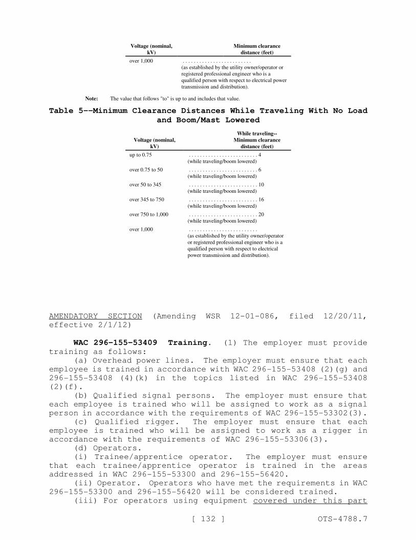
Voltage (nominal,
kV)
Minimum clearance
distance (feet)
[ 132 ] OTS-4788.7
over 1,000 . . . . . . . . . . . . . . . . . . . . . . . . .
(as established by the utility owner/operator or
registered professional engineer who is a
qualified person with respect to electrical power
transmission and distribution).
Note: The value that follows "to" is up to and includes that value.
Table 5--Minimum Clearance Distances While Traveling With No Load
and Boom/Mast Lowered
Voltage (nominal,
kV)
While traveling--
Minimum clearance
distance (feet)
up to 0.75 . . . . . . . . . . . . . . . . . . . . . . . . . 4
(while traveling/boom lowered)
over 0.75 to 50 . . . . . . . . . . . . . . . . . . . . . . . . . 6
(while traveling/boom lowered)
over 50 to 345 . . . . . . . . . . . . . . . . . . . . . . . . . 10
(while traveling/boom lowered)
over 345 to 750 . . . . . . . . . . . . . . . . . . . . . . . . . 16
(while traveling/boom lowered)
over 750 to 1,000 . . . . . . . . . . . . . . . . . . . . . . . . . 20
(while traveling/boom lowered)
over 1,000 . . . . . . . . . . . . . . . . . . . . . . . . .
(as established by the utility owner/operator
or registered professional engineer who is a
qualified person with respect to electrical
power transmission and distribution).
AMENDATORY SECTION (Amending WSR 12-01-086, filed 12/20/11,
effective 2/1/12)
WAC 296-155-53409 Training. (1) The employer must providetraining as follows:
(a) Overhead power lines. The employer must ensure that each
employee is trained in accordance with WAC 296-155-53408 (2)(g) and
296-155-53408 (4)(k) in the topics listed in WAC 296-155-53408
(2)(f).
(b) Qualified signal persons. The employer must ensure that
each employee is trained who will be assigned to work as a signal
person in accordance with the requirements of WAC 296-155-53302(3).
(c) Qualified rigger. The employer must ensure that each
employee is trained who will be assigned to work as a rigger in
accordance with the requirements of WAC 296-155-53306(3).
(d) Operators.
(i) Trainee/apprentice operator. The employer must ensure
that each trainee/apprentice operator is trained in the areas
addressed in WAC 296-155-53300 and 296-155-56420.
(ii) Operator. Operators who have met the requirements in WAC
296-155-53300 and 296-155-56420 will be considered trained.
(iii) For operators using equipment covered under this part
[ 133 ] OTS-4788.7
that are exempt in WAC 296-155-52900 (3)(b), the employer must
ensure that each operator is trained on the safe operation of the
equipment the operator will be using.
(e) The employer must train each operator of the equipment
covered by this part in the following practices:
(i) On friction equipment, whenever moving a boom off a
support, first raise the boom a short distance (sufficient to take
the load of the boom) to determine if the boom hoist brake needs to
be adjusted. On other types of equipment with a boom, the same
practice is applicable, except that typically there is no means of
adjusting the brake; if the brake does not hold, a repair is
necessary. See WAC 296-155-53400 (68) and (69).
(ii) Where available, the manufacturer's emergency procedures
for halting unintended equipment movement.
(f) Competent persons and qualified persons. The employer
must ensure that each competent person and each qualified person is
trained regarding the requirements of this part applicable to their
respective roles.
(((f))) (g) Crush/pinch points. The employer must ensure that
each employee is trained who works with the equipment to keep clear
of holes, and crush/pinch points and the hazards addressed in WAC
296-155-53400(42) (work area control).
(((g))) (h) Tag-out. The employer must ensure that each
operator and each additional employee authorized to start/energize
equipment or operate equipment controls (such as maintenance and
repair employees) is trained, in the tag-out and start-up
procedures in WAC 296-155-53400 (16) and (67).
(2) Training administration.
(a) The employer must evaluate each employee required to be
trained under this part to confirm that the employee understands
the information provided in the training.
(b) The employer must ensure that refresher training is
provided in relevant topics for each employee when, based on the
conduct of the employee or an evaluation of the employee's
knowledge, there is an indication that retraining is necessary.
(c) Whenever the employer is required to provide training
under this part, the employer must provide the training at no cost
to the employee.
AMENDATORY SECTION (Amending WSR 12-01-086, filed 12/20/11,
effective 2/1/12)
WAC 296-155-54200 Overhead/bridge and gantry cranes--General.(1) Permanently installed overhead/bridge and gantry cranes which
are located in a manufacturing facility or powerhouse must follow
the requirements of WAC 296-24-235 (General safety and health
standards), even when a construction activity is being performed.
This requirement applies to overhead, bridge, gantry cranes,
including semigantry, cantilever gantry, wall cranes, storage
[ 134 ] OTS-4788.7
bridge cranes, and others having the same fundamental
characteristics.
(2) Overhead and gantry cranes that are not permanently
installed ((in a manufacturing facility or a powerhouse)) must
follow the applicable requirements in chapter 296-155 WAC Part L.
(3) Cranes included in this section must meet the applicable
requirements for design, inspection, construction, testing,
maintenance and operation as prescribed in:
(a) ASME B30.2-2005, Safety Standard for Overhead and Gantry
Cranes (Top Running Bridge, Single or Multiple Girder, Top Running
Trolley Hoist).
(b) ASME B30.11-2010, Safety Standards for Monorails and
Underhung Cranes.
(c) ASME B30.17-2006, Safety Standards for Overhead and Gantry
Cranes (Top Running Bridge, Single Girder, Underhung Hoist).
(d) It is not the intent of this rule to require retrofitting
of existing cranes. However, when an item is being modified, its
performance needs to be reviewed by a qualified person and compared
to the applicable sections of this rule. For modification
requirements see WAC 296-155-53400 (58) and (59). For cranes
manufactured prior to the effective date of this rule the design
and construction criteria must meet at a minimum, ASME B30.2.0-
1990.
(4) The rated load of the crane must be plainly marked on each
side of the crane, and if the crane has more than one hoisting
unit, each hoist must have its rated load marked on it or its load
block, and this marking must be clearly legible from the ground or
floor.
(5) The crane or surrounding structure must be marked to
provide operating directions that match and are visible from the
crane's operating controls, i.e., north/south, east/west or
forward/back, left/right.
(6) Overhead and gantry cranes with bridge trucks must be
equipped with sweeps which extend below the top of the rail and
project in front of the truck wheels.
(7) Except for floor-operated cranes, an effective warning
device must be provided for each crane equipped with a power
traveling mechanism.
(8) A wind-indicating device must be provided for all outdoor
overhead and gantry cranes. The device must be mounted on the
crane runway structure and must give a visible and audible alarm to
the crane operator at a predetermined wind velocity. A single
wind-indicating device may serve as an alarm for more than one
crane.
(9) Electrical.
(a) Wiring and equipment must comply with Article 610 of
ANSI/NFPA No. 70, National Electrical Code and chapter 296-155 WAC
Part I.
(b) The control circuit voltage must not exceed 600 volts for
AC or DC.
(c) The voltage at pendant pushbuttons must not exceed 150
volts for AC and 300 volts for DC.
(d) Where multiple conductor cable is used with a suspended
[ 135 ] OTS-4788.7
pushbutton station, the station must be supported in a manner that
will protect the electrical conductors against strain.
(e) Pendant control stations must be constructed to prevent
electrical shock. The pushbutton enclosure must be at ground
potential and marked for identification of functions.
(10) All welding procedures and welding operator
qualifications to be used on load sustaining members must be in
accordance with ANSI/AWS D1.1, except as modified by ANSI/AWS
D14.1.
AMENDATORY SECTION (Amending WSR 12-01-086, filed 12/20/11,
effective 2/1/12)
WAC 296-155-54410 Sideboom cranes. (1) The provisions ofthis standard apply, except WAC 296-155-53400(34) (Ground
conditions), WAC 296-155-53410 (Safety devices), WAC 296-155-53412
(Operational aids), WAC ((296-155-52900)) 296-155-531 through 296-
155-53214 (crane certifier accreditation and crane certification)
and WAC 296-155-53300 (Operator qualifications and certification).
(2) Sideboom cranes manufactured prior to the effective date
of this section must meet the requirements of SAE J743a-1964.
Sideboom cranes mounted on wheel or crawler tractors manufactured
after the effective date of this section must meet the requirements
of ASME B30.14-2010.
AMENDATORY SECTION (Amending WSR 12-01-086, filed 12/20/11,
effective 2/1/12)
WAC 296-155-55110 Proof load test platforms and rigging. (1)The platform and rigging must be proof load tested at each new
location before lifting personnel. This may be done at the same
time as the trial lift.
(a) Test as follows:
(i) Test to one hundred twenty-five percent of the platform's
rated capacity.
(ii) The platform must be ((hoisted, then)) lowered by
controlled load lowering, braked, and held in a suspended position
for a minimum of five minutes with the test load evenly distributed
on the platform.
(b) Do the following after proof load testing:
(i) A qualified person must inspect the platform and rigging
to determine if the test has passed.
(ii) Any deficiencies that pose a safety hazard must be
corrected prior to lifting personnel.
[ 136 ] OTS-4788.7
(iii) Another test must be performed after any deficiencies
are corrected.
(c) Keep the most recent proof load testing records available
at the job site.
(d) Personnel hoisting must not be conducted until a qualified
person determines that the platform and rigging has successfully
passed the proof load test.
(2) The platform and rigging must be proof load tested after
any structural repair or modification, before lifting personnel.
(a) Test suspended platforms in the following order:
(i) Test to one hundred fifty percent of the platform's rated
capacity;
(ii) The loaded platform must be raised, then lower it at a
speed of at least one hundred ft/min;
(iii) Bring the platform to a stop by using the crane/derrick
brakes;
(iv) The platform must hang for at least five minutes;
(v) A qualified person must inspect the platform and rigging;
(vi) Any deficiencies must be corrected;
(vii) Another test must be performed after any deficiencies
are corrected.
(b) Test attached platforms in the following order:
(i) Test to one hundred twenty-five percent of the platform's
rated capacity;
(ii) Hold the platform suspended for five minutes with the
test load evenly distributed on the platform;
(iii) A qualified person must inspect the platform and
rigging;
(iv) Any deficiencies must be corrected;
(v) Another test must be performed after any deficiencies are
corrected.
(c) The most recent proof load testing records must be kept
and available at the job site.
AMENDATORY SECTION (Amending WSR 12-01-086, filed 12/20/11,
effective 2/1/12)
WAC 296-155-55115 Trial lift. (1) A trial lift must beperformed with the personnel platform, on each shift before lifting
personnel, to check the following:
(a) Crane/derrick setup and configuration is correct;
(b) Load capacities are adequate;
(c) No hazardous interferences exist;
(d) The operator's operational competence.
(2) A trial lift with the unoccupied personnel platform loaded
at least to the anticipated lift-weight must be made from ground
level, or any other location where employees will enter the
platform, to each location at which the platform is to be hoisted
and positioned. Where there is more than one location to be
[ 137 ] OTS-4788.7
reached from a single set-up position, either individual trial
lifts for each location, or a single trial lift, in which the
platform is moved sequentially to each location, must be performed;
the method selected must be the same as the method that will be
used to hoist the personnel.
(3) The trial lift must be repeated before lifting personnel
whenever:
(a) The crane or derrick is moved and set up in a different
location or returned to a previously used location;
(b) The crane or derrick is reconfigured;
(c) The operator is changed;
(d) The lift route has changed, unless the competent person
determines that the new route presents no new factors affecting
safety.
(4) A competent person must determine that:
(a) Safety devices and operational aids required by this
section are activated and functioning properly. Other safety
devices and operational aids must meet the requirements of WAC 296-
155-53410 and 296-155-53412.
(b) Nothing interferes with the crane/derrick or the personnel
platform in the course of the trial lift.
(c) The lift will not exceed fifty percent of the
crane/derrick's rated capacity at any time during the lift.
(d) The load radius to be used during the lift has been
accurately determined.
(5) Immediately after the trial lift, a competent person must:
(a) Conduct a visual inspection of the crane/derrick, base
support or ground, and personnel platform, to determine whether the
trial lift has exposed any defect or problem or produced any
adverse effect.
(b) Confirm that, upon the completion of the trial lift
process, the test weight has been removed.
(6) Immediately prior to each lift:
(a) The platform must be hoisted a few inches with the
personnel and materials/tools on board and inspected by a competent
person to ensure that it is secure and properly balanced.
(b) The following conditions must be determined by a competent
person to exist before the lift of personnel proceeds:
(i) Hoist ropes must be free of deficiencies in accordance
with WAC 296-155-53404.
(ii) Multiple part lines must not be twisted around each
other.
(iii) The primary attachment must be centered over the
platform.
(iv) If the load rope is slack, the hoisting system must be
inspected to ensure that all ropes are properly seated on drums and
in sheaves.
(7) Any condition found during the trial lift and subsequent
inspection(s) that fails to meet a requirement of this standard or
otherwise creates a safety hazard must be corrected before hoisting
personnel.
[ 138 ] OTS-4788.7
AMENDATORY SECTION (Amending WSR 12-01-086, filed 12/20/11,
effective 2/1/12)
WAC 296-155-55210 Crane or derrick operation requirements for
personnel lifting. (1) Before lifting personnel the following mustbe met:
(a) Operate crane/derrick with outriggers or stabilizers
extended, blocked, and locked in accordance with the manufacturers'
specifications;
(b) For crane/derrick that uses wire rope to hoist a personnel
platform, verify that the crane/derrick has an anti two-block
device or upper travel limit switch, installed and operational;
(c) Position the personnel platform so that it may be tied off
to the structure to which the occupants are entering or leaving, if
the platform cannot be landed during the entrance or exit of the
occupants. If the platform has been tied off, the operator must
not move the platform until it is verified that it is freely
suspended;
(d) Not knowingly allow the platform load to exceed the
platform rating, except during proof testing;
(e) Not travel the crane/derrick with personnel in the
personnel platform except when they run on fixed rails or runways;
(f) Perform all movements of the platform or crane/derrick in
a slow, controlled, cautious manner to minimize sudden movement of
the platform;
(g) Engage the power-controlled lowering mechanism at all
times the platform is occupied (no freefall);
(h) In the case of suspended or boom-mounted platforms,
without controls, the operator must remain at the crane/derrick
controls at all times when the platform is occupied;
(i) Reserved;
(j) Platforms with controls. Where the platform is equipped
with controls, all of the following must be met at all times while
the platform is occupied:
(i) The occupant using the controls in the platform must be a
qualified person with respect to their use, including the safe
limitations of the crane/derrick and hazards associated with its
operation. See WAC 296-155-53300, Operator qualifications and
certification.
(ii) The crane/derrick operator must be at a set of crane
controls that include boom and swing functions of the crane, ((or))
and must be on-site and in view of the crane/derrick and platform.
(iii) The platform operating manual must be in the platform or
on the crane/derrick.
Note: If lowering, retracting, and rotating primary power source becomes inoperative, the crane/derrick operator is allowed to
leave the controls.
(k) Set all brakes and locks on the crane/derrick after
positioning of the personnel platform and before personnel perform
any work;
(l) Move the platform under controlled conditions and under
the direction of a qualified signal person or platform occupant(s);
(m) Not move platforms over, under, or in the vicinity of
[ 139 ] OTS-4788.7
power lines unless the requirements of WAC 296-155-55305 are met;
(n) Not lift any other loads, on any other load lines, while
conducting a personnel lift. When the crane/derrick has a boom-
attached platform without controls, it must not be used for other
lifting service;
(o) Factory-produced boom-mounted personnel platforms that
incorporate a winch as original equipment: Loads are permitted to
be hoisted by such a winch while employees occupy the personnel
platform only where the load on the winch line does not exceed five
hundred pounds and does not exceed the rated capacity of the winch
and platform, and does not exceed fifty percent of the crane's
rated capacity at the radius and configuration used;
(p) Not disable, or allow to be disabled, any crane/derrick
safety device during a personnel lift;
(q) Hoist the platform at a speed suitable for the safety of
the operation but in no case in excess of ninety feet/minute (30
m/minute) or 1.5 feet/second (0.5 m/second).
(2) The operator must not move the platform without a
discernible or audible signal from a signal person.
AMENDATORY SECTION (Amending WSR 12-01-086, filed 12/20/11,
effective 2/1/12)
WAC 296-155-55300 Personnel lifting requirements. (1)
Conditions must provide clear visibility. When conditions such as
darkness, fog, or snow prevent clear visibility, a personnel lift
must not be performed.
(2) Personnel platforms cannot be used in winds (sustained or
gusts) in excess of twenty mph (32.2 km/hr) or in electric storms,
snow, ice, sleet, or other adverse weather conditions which could
affect the safety of personnel.
(3) Other weather and environmental conditions. A qualified
person must determine if, in light of indications of dangerous
weather conditions, or other impending or existing danger, it is
not safe to lift personnel. If it is not, the lifting operation
must not begin (or, if already in progress, must be terminated).
(4) Personnel platforms must only be used for personnel, their
tools, and sufficient material to do their work. They must not be
used for solely transporting bulk materials.
(5) The number of employees occupying the personnel platform
must not exceed the maximum number the platform was designed to
hold or the number required to perform the work, whichever is less.
(6) A qualified person must evaluate the safety concerns of
the operational environment and verify the platform and
crane/derrick are suitable for use. Additionally, special work
circumstances may require further precautions. Precautions such
as, but not limited to, the following must be taken:
(a) When welding is to be accomplished from the personnel
platform, suitable electrode holders must be provided to protect
[ 140 ] OTS-4788.7
them from contact with any conducting components of the platform.
(b) Operators of cranes/derricks, installed on floating
vessels, must be instructed not to lift personnel when the list or
trim of the vessel exceeds five degrees. If a mobile crane/derrick
is placed on floating vessels, operators must not lift personnel
when the list or trim of the vessel exceeds one degree.
(c) Personnel fall protection devices with quick release
features must be provided and required to be worn. The fall
protection device must be appropriately attached while personnel
are lifted over land and detached while personnel are lifted over
water. See Part C-1 of this chapter for requirements for fall
arrest system, including the attachment point (anchorage) used to
comply with this subsection. When personnel lifts are conducted
over water, U.S. Coast Guard approved (Type I, II, III, or V)
personnel flotation devices must be provided and required to be
worn.
(d) A boat/skiff with appropriate rescue personnel must be
readily available at all times during a personnel lift over water.
(e) Appropriate personnel protective equipment must be
provided and required to be used around toxic, flammable, or
hazardous substances or fumes.
(f) Any concentrated loading of the platform must be reviewed
to preclude the overstressing of any component or impairing the
platform stability.
(g) Where the rotation of the platform, while hoisted, can
create a hazard, appropriate restraining methods must be provided
and required to be used.
(7) In order to safely perform the personnel lift, make sure
the following are met:
(a) The personnel platform is not loaded with more than itsrated load capacity;
(b) Materials and tools being lifted by a platform are:
(i) Secured to prevent movement;
(ii) Evenly distributed on the platform.
(c) The personnel platform is hoisted slowly, with no sudden
movements;
(d) Tag lines are used to control the motion of suspended
platforms, unless using them creates a hazard;
(e) The platform is secured to the structure where the work
will be performed before employees exit or enter the platform,
unless securing to the structure is unsafe;
(f) No other load lines on the crane or derrick are used to
lift anything while personnel are on a platform;
(g) Brakes and locking devices are engaged when the personnel
platform is occupied and in a stationary working position;
(h) The lowering motion of the hoist line and/or the boom is
power-controlled only. Free fall is not allowed;(8) The platform operation instructions in this rule are
intended as minimum criteria. The platform manufacturer's
information must be consulted for specific instruction on the
platform's operation.
(9) Traveling.

[ 141 ] OTS-4788.7
(a) Rubber tired cranes are not allowed to travel while
lifting personnel. Hoisting of employees while the crane is
traveling is only allowed when:
(i) The crane travels on fixed rails; or
(ii) The crane has crawlers and is on a runway, and the
employer demonstrates that there is no less hazardous way to
perform the work.
(b) Where employees are hoisted while the crane is traveling,
the following criteria must be met:
(i) Crane travel must be restricted to a fixed track or
runway.
(ii) Where a runway is used, it must be a firm, level surface
designed, prepared and designated as a path of travel for the
weight and configuration of the crane/derrick being used to lift
and travel with the personnel platform. An existing surface may be
used as long as it meets these criteria.
(iii) Travel must be limited to boom length.
(iv) The boom must be parallel to the direction of travel,
except where it is safer to do otherwise.
(v) A complete trial run must be performed to test the route
of travel before employees are allowed to occupy the platform.
This trial run can be performed at the same time as the trial lift
required by WAC 296-155-55115 which tests the lift route.
(10) Derricks are prohibited from traveling while personnel
are hoisted.
(11) Platform occupants must remain in continuous sight or in
communication with the operator and in sight and communication of
a signal person.
(12) Platform occupants must use personnel protective
equipment, such as hard hats, safety glasses, hearing protection,
and gloves, in conditions where a hazard of injury exists.
(13) Platform occupants must wear personnel fall protection
devices with lanyards attached to a specific anchorage point(s),
unless special work circumstance requirements dictate otherwise,
such as working over water.
(14) Platform occupants must keep all parts of the body inside
the platform during raising, lowering, and horizontal movement.
This provision does not apply to an occupant of the platform when
necessary to position the platform or while performing the duties
of a signal person.
(15) Platform occupants must not stand, sit on, or work from
the top rail, intermediate rail, toe board, or use any other device
to enhance their vertical height working capability.
(16) Platform occupants must not pull the platform out of
plumb in relation to the crane/derrick.
(17) Platform occupants must not enter or exit a suspended
platform while it is raised unless the platform has an installed
gate and is physically secured to the structure to which the
occupants are entering or exiting unless the employer can
demonstrate that securing to the structure would create a greater
hazard.
(18) Platform occupants must not operate a platform with
motion controls without the platform operation manual available in
[ 142 ] OTS-4788.7
the platform.
(19) If the platform is tied to the structure, the operator
must not move the platform until the operator receives confirmation
that it is freely suspended.
(20) The platform must be inspected prior to each lift to
verify all attachments and the platform are safe to use.
(21) Verify the platform is evenly loaded, material secured,
and the total platform weight does not exceed the platform rating
or the reduced crane/derrick lift capacity.
(22) Communication requirements.
(a) Hand signals to the operator must be in accordance with
the applicable crane/derrick portion of this part.
(b) Signals must be discernable or audible to the operator.
(c) Hand signals must be posted conspicuously at the following
locations:
(i) On the crane/derrick as required by this part.
(ii) Inside the personnel platform.
(iii) At any platform motion control locations.
(d) Some operations may require additions to or modifications
of standard signals.
(i) Any special signals must be agreed upon and understood by
the signal persons and crane/derrick operator.
(ii) Special signs must not conflict with the crane/derrick
standard signals.
(e) No response must be made unless signals are clearly
understood.
(f) If communications between operator and platform occupants
are disrupted, all operations must be stopped until communication
is reestablished.
(g) Communication systems to be used during the lift must be
verified as functioning and effective prior to commencing the lift.
Note: If radios or other electronic means of communication are used, they should operate on a secure channel.
AMENDATORY SECTION (Amending WSR 12-01-086, filed 12/20/11,
effective 2/1/12)
WAC 296-155-556 Rigging--General requirements. ((The riggingrequirements in this part apply to all construction activities.))
[ 143 ] OTS-4788.7
AMENDATORY SECTION (Amending WSR 12-01-086, filed 12/20/11,
effective 2/1/12)
WAC 296-155-55600 General requirements. (1) Employers mustuse at least one qualified rigger((s)) as follows:
(a) During hoisting activities for assembly and disassembly
work (WAC 296-155-53402 (19)(a))((. Additionally, qualified
riggers are required));
(b) Whenever ((workers)) employees are ((within the fall zone
and)) engaged in hooking, unhooking, or guiding a load, or
((doing)) in the initial connection of a load to a component or
structure, and are within the fall zone (WAC 296-155-53400
(43)(c)).
Note: See qualified rigger requirements located in WAC 296-155-53306 of this part.
(2) All slings in use must meet the applicable requirements
for design, inspection, construction, testing, maintenance and
operation as prescribed in ASME B30.9-2010.
(3) All rigging hardware in use must meet the applicable
requirements for design, inspection, construction, testing,
maintenance and operation as prescribed in ASME B30.26-2010.
(4) All rigging gear must be used in accordance with the
manufacturer's recommendations or a qualified person.
(5) All below-the-hook lifting devices in use must meet the
applicable requirements for design, inspection, construction,
testing, maintenance and operation as prescribed in ASME B30.20-
2010.
(6) All hooks in use must meet the applicable requirements for
design, inspection, construction, testing, maintenance and
operation as prescribed in ASME B30.10-2009.
(7) Repair of hooks must be approved by the manufacturer or
qualified person and as follows:
(a) Cracks, nicks, and gouges may be repaired by a competent
person, all other repairs are done by the manufacturer or a
qualified person;
(b) Grind longitudinally, following the contour of the hook;
(c) Do not reduce the dimension of the hook more than ten
percent from the original.
(8) Hooks must not be modified by welding and/or drilling
unless written approval by the manufacturer has been received.
(9) Special custom design grabs, hooks, clamps, or other
lifting accessories, for such units as modular panels,
prefabricated structures and similar materials, must be marked to
indicate the safe working loads and must be proof tested prior to
use to one hundred and twenty-five percent of their rated load.
(10) A qualified person must inspect the rigging equipment
before each day or shift and:
(a) Consider the application the equipment will be used for,
and determine if it's safe for use;
(b) Remove the equipment from service if using it will create
a hazard or meets any of the removal criteria listed in this
chapter.
(((10))) (11) The rated load of the rigging equipment must not
[ 144 ] OTS-4788.7
be exceeded.
(12) All rigging hardware must have permanently affixed and
legible identification markings as prescribed by the manufacturer
that indicate the recommended safe working load.
(((11))) (13) All rigging hardware must be inspected in
accordance with Table 11, each day before using. If a daily
inspection is not feasible because the hardware is in a
semipermanent or inaccessible location, a periodic inspection is
allowed instead of daily.
(((12))) (14) Rigging hardware must be removed from service
when it shows any conditions listed in Table 11, or any other
hazardous condition.
Table 11
Rigging Hardware Inspection/Removal Criteria
For all hardware, inspect for the following:
Missing or illegible identification.
Indications of heat damage, including weld spatter or arc
strikes.
Excessive pitting or corrosion.
Load bearing components that are:
! Bent;
! Twisted;
! Distorted;
! Stretched;
! Elongated;
! Cracked;
! Broken.
Excessive nicks or gouges.
10% reduction of the original or catalog dimension at any
point.
Excessive thread damage or wear, where applicable.
Evidence of unauthorized welding or modification.
Any other conditions that cause doubt as to the safety of
continued use.
On shackles, also inspect for incomplete pin
engagement.
On swivels and swivel hoist rings, check for lack of
ability to freely rotate or pivot.
On compression hardware, also check for:
Unauthorized replacement components;
Insufficient number of wire rope clips;
Improperly tightened wire rope clips;
Damaged wire rope;
Indications of wire rope slippage;
Improper assembly.
On swivels, check for loose or missing nuts, bolts, cotter
pins, snap rings, or other fasteners and retaining devices.
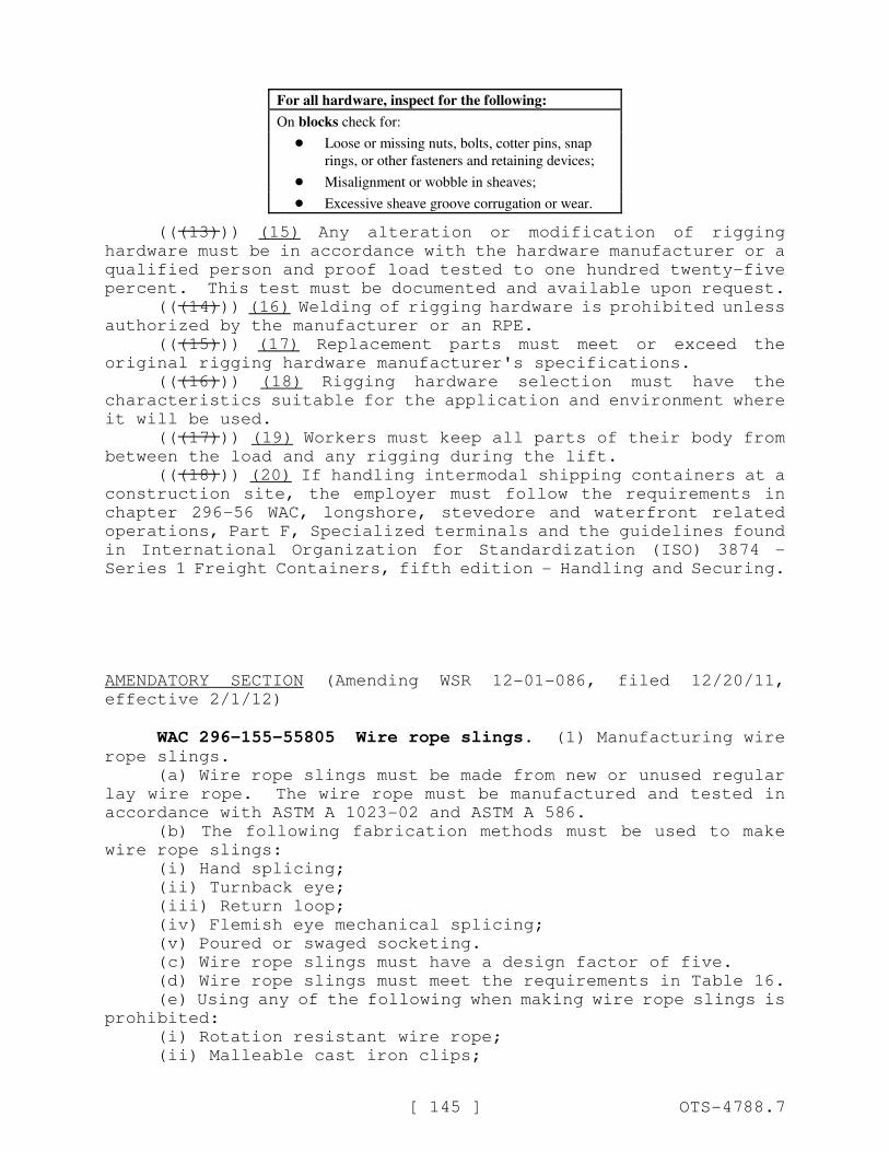
For all hardware, inspect for the following:
[ 145 ] OTS-4788.7
On blocks check for:
! Loose or missing nuts, bolts, cotter pins, snap
rings, or other fasteners and retaining devices;
! Misalignment or wobble in sheaves;
! Excessive sheave groove corrugation or wear.
(((13))) (15) Any alteration or modification of rigging
hardware must be in accordance with the hardware manufacturer or a
qualified person and proof load tested to one hundred twenty-five
percent. This test must be documented and available upon request.
(((14))) (16) Welding of rigging hardware is prohibited unless
authorized by the manufacturer or an RPE.
(((15))) (17) Replacement parts must meet or exceed the
original rigging hardware manufacturer's specifications.
(((16))) (18) Rigging hardware selection must have the
characteristics suitable for the application and environment where
it will be used.
(((17))) (19) Workers must keep all parts of their body from
between the load and any rigging during the lift.
(((18))) (20) If handling intermodal shipping containers at a
construction site, the employer must follow the requirements in
chapter 296-56 WAC, longshore, stevedore and waterfront related
operations, Part F, Specialized terminals and the guidelines found
in International Organization for Standardization (ISO) 3874 -
Series 1 Freight Containers, fifth edition - Handling and Securing.
AMENDATORY SECTION (Amending WSR 12-01-086, filed 12/20/11,
effective 2/1/12)
WAC 296-155-55805 Wire rope slings. (1) Manufacturing wirerope slings.
(a) Wire rope slings must be made from new or unused regular
lay wire rope. The wire rope must be manufactured and tested in
accordance with ASTM A 1023-02 and ASTM A 586.
(b) The following fabrication methods must be used to make
wire rope slings:
(i) Hand splicing;
(ii) Turnback eye;
(iii) Return loop;
(iv) Flemish eye mechanical splicing;
(v) Poured or swaged socketing.
(c) Wire rope slings must have a design factor of five.
(d) Wire rope slings must meet the requirements in Table 16.
(e) Using any of the following when making wire rope slings is
prohibited:
(i) Rotation resistant wire rope;
(ii) Malleable cast iron clips;
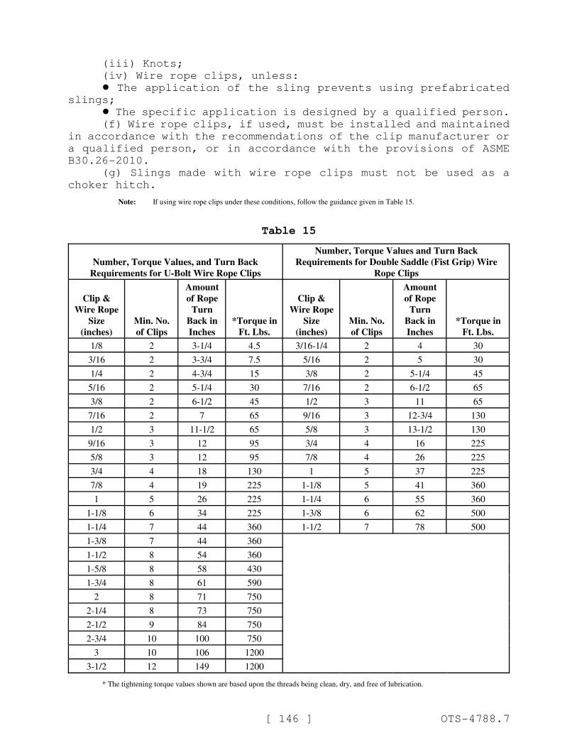
[ 146 ] OTS-4788.7
(iii) Knots;
(iv) Wire rope clips, unless:
! The application of the sling prevents using prefabricated
slings;
! The specific application is designed by a qualified person.
(f) Wire rope clips, if used, must be installed and maintained
in accordance with the recommendations of the clip manufacturer or
a qualified person, or in accordance with the provisions of ASME
B30.26-2010.
(g) Slings made with wire rope clips must not be used as a
choker hitch.
Note: If using wire rope clips under these conditions, follow the guidance given in Table 15.
Table 15
Number, Torque Values, and Turn Back
Requirements for U-Bolt Wire Rope Clips
Number, Torque Values and Turn Back
Requirements for Double Saddle (Fist Grip) Wire
Rope Clips
Clip &
Wire Rope
Size
(inches)
Min. No.
of Clips
Amount
of Rope
Turn
Back in
Inches
.*Torque in
Ft. Lbs.
Clip &
Wire Rope
Size
(inches)
Min. No.
of Clips
Amount
of Rope
Turn
Back in
Inches
.*Torque in
Ft. Lbs.
1/8 2 3-1/4 4.5 3/16-1/4 2 4 30
3/16 2 3-3/4 7.5 5/16 2 5 30
1/4 2 4-3/4 15 3/8 2 5-1/4 45
5/16 2 5-1/4 30 7/16 2 6-1/2 65
3/8 2 6-1/2 45 1/2 3 11 65
7/16 2 7 65 9/16 3 12-3/4 130
1/2 3 11-1/2 65 5/8 3 13-1/2 130
9/16 3 12 95 3/4 4 16 225
5/8 3 12 95 7/8 4 26 225
3/4 4 18 130 1 5 37 225
7/8 4 19 225 1-1/8 5 41 360
1 5 26 225 1-1/4 6 55 360
1-1/8 6 34 225 1-3/8 6 62 500
1-1/4 7 44 360 1-1/2 7 78 500
1-3/8 7 44 360
1-1/2 8 54 360
1-5/8 8 58 430
1-3/4 8 61 590
2 8 71 750
2-1/4 8 73 750
2-1/2 9 84 750
2-3/4 10 100 750
3 10 106 1200
3-1/2 12 149 1200
.* The tightening torque values shown are based upon the threads being clean, dry, and free of lubrication.
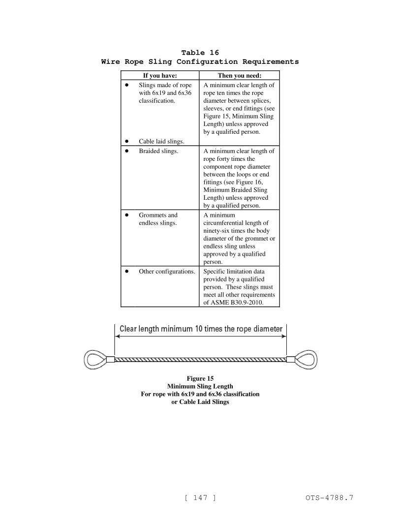
[ 147 ] OTS-4788.7
Table 16
Wire Rope Sling Configuration Requirements
If you have: Then you need:
! Slings made of rope
with 6x19 and 6x36
classification.
A minimum clear length of
rope ten times the rope
diameter between splices,
sleeves, or end fittings (see
Figure 15, Minimum Sling
Length) unless approved
by a qualified person.
! Cable laid slings.
! Braided slings. A minimum clear length of
rope forty times the
component rope diameter
between the loops or end
fittings (see Figure 16,
Minimum Braided Sling
Length) unless approved
by a qualified person.
! Grommets and
endless slings.
A minimum
circumferential length of
ninety-six times the body
diameter of the grommet or
endless sling unless
approved by a qualified
person.
! Other configurations. Specific limitation data
provided by a qualified
person. These slings must
meet all other requirements
of ASME B30.9-2010.
Figure 15
Minimum Sling Length
For rope with 6x19 and 6x36 classification
or Cable Laid Slings
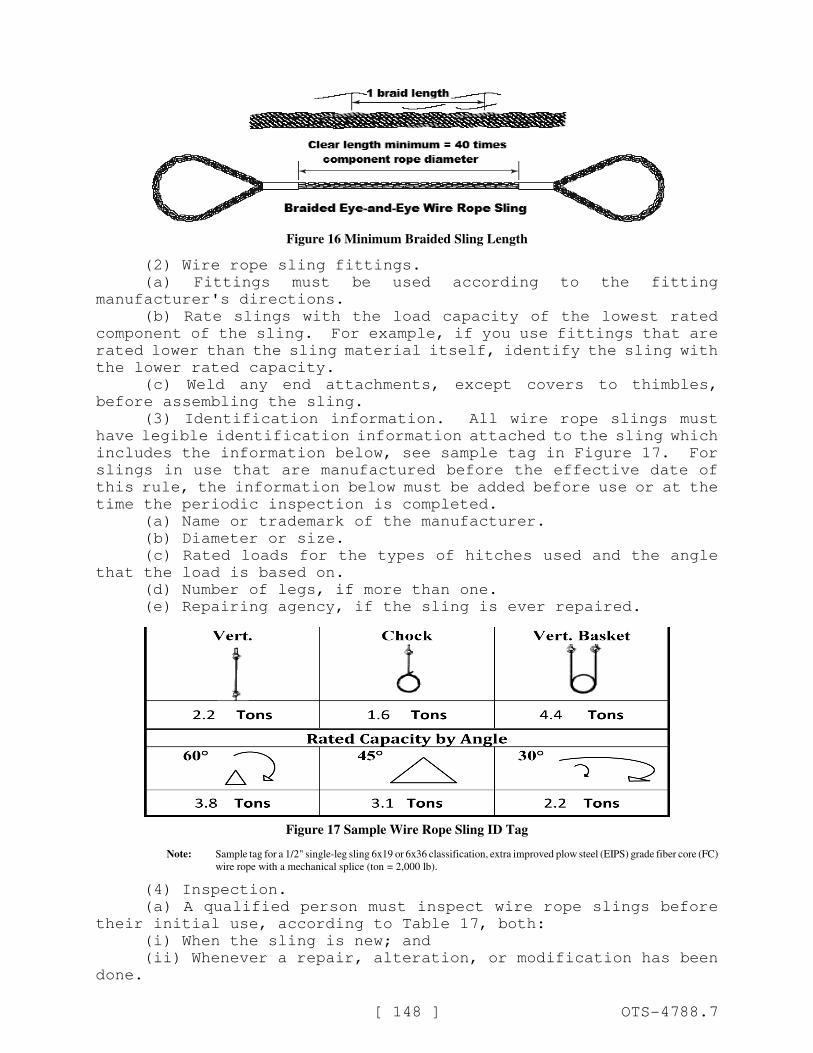
[ 148 ] OTS-4788.7
Figure 16 Minimum Braided Sling Length
(2) Wire rope sling fittings.
(a) Fittings must be used according to the fitting
manufacturer's directions.
(b) Rate slings with the load capacity of the lowest rated
component of the sling. For example, if you use fittings that are
rated lower than the sling material itself, identify the sling with
the lower rated capacity.
(c) Weld any end attachments, except covers to thimbles,
before assembling the sling.
(3) Identification information. All wire rope slings must
have legible identification information attached to the sling which
includes the information below, see sample tag in Figure 17. For
slings in use that are manufactured before the effective date of
this rule, the information below must be added before use or at the
time the periodic inspection is completed.
(a) Name or trademark of the manufacturer.
(b) Diameter or size.
(c) Rated loads for the types of hitches used and the angle
that the load is based on.
(d) Number of legs, if more than one.
(e) Repairing agency, if the sling is ever repaired.
Figure 17 Sample Wire Rope Sling ID Tag
Note: Sample tag for a 1/2" single-leg sling 6x19 or 6x36 classification, extra improved plow steel (EIPS) grade fiber core (FC)
wire rope with a mechanical splice (ton .= 2,000 lb).
(4) Inspection.
(a) A qualified person must inspect wire rope slings before
their initial use, according to Table 17, both:
(i) When the sling is new; and
(ii) Whenever a repair, alteration, or modification has been
done.
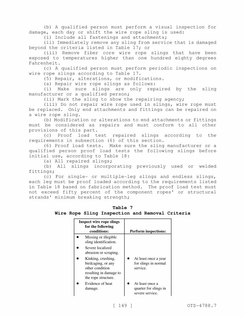
[ 149 ] OTS-4788.7
(b) A qualified person must perform a visual inspection for
damage, each day or shift the wire rope sling is used:
(i) Include all fastenings and attachments;
(ii) Immediately remove any sling from service that is damaged
beyond the criteria listed in Table 17; or
(iii) Remove fiber core wire rope slings that have been
exposed to temperatures higher than one hundred eighty degrees
Fahrenheit.
(c) A qualified person must perform periodic inspections on
wire rope slings according to Table 17.
(5) Repair, alterations, or modifications.
(a) Repair wire rope slings as follows:
(i) Make sure slings are only repaired by the sling
manufacturer or a qualified person;
(ii) Mark the sling to show the repairing agency;
(iii) Do not repair wire rope used in slings, wire rope must
be replaced. Only end attachments and fittings can be repaired on
a wire rope sling.
(b) Modification or alterations to end attachments or fittings
must be considered as repairs and must conform to all other
provisions of this part.
(c) Proof load test repaired slings according to the
requirements in subsection (6) of this section.
(6) Proof load tests. Make sure the sling manufacturer or a
qualified person proof load tests the following slings before
initial use, according to Table 18:
(a) All repaired slings;
(b) All slings incorporating previously used or welded
fittings;
(c) For single- or multiple-leg slings and endless slings,
each leg must be proof loaded according to the requirements listed
in Table 18 based on fabrication method. The proof load test must
not exceed fifty percent of the component ropes' or structural
strands' minimum breaking strength;
Table 7
Wire Rope Sling Inspection and Removal Criteria
Inspect wire rope slings
for the following
conditions: Perform inspections:
! Missing or illegible
sling identification.
! Severe localized
abrasion or scraping.
! Kinking, crushing,
birdcaging, or any
other condition
resulting in damage to
the rope structure.
! At least once a year
for slings in normal
service.
! Evidence of heat
damage.
! At least once a
quarter for slings in
severe service.
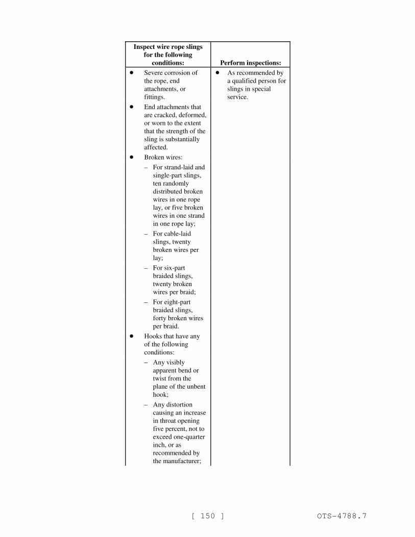
Inspect wire rope slings
for the following
conditions: Perform inspections:
[ 150 ] OTS-4788.7
! Severe corrosion of
the rope, end
attachments, or
fittings.
! As recommended by
a qualified person for
slings in special
service.
! End attachments that
are cracked, deformed,
or worn to the extent
that the strength of the
sling is substantially
affected.
! Broken wires:
– For strand-laid and
single-part slings,
ten randomly
distributed broken
wires in one rope
lay, or five broken
wires in one strand
in one rope lay;
– For cable-laid
slings, twenty
broken wires per
lay;
– For six-part
braided slings,
twenty broken
wires per braid;
– For eight-part
braided slings,
forty broken wires
per braid.
! Hooks that have any
of the following
conditions:
– Any visibly
apparent bend or
twist from the
plane of the unbent
hook;
– Any distortion
causing an increase
in throat opening
five percent, not to
exceed one-quarter
inch, or as
recommended by
the manufacturer;
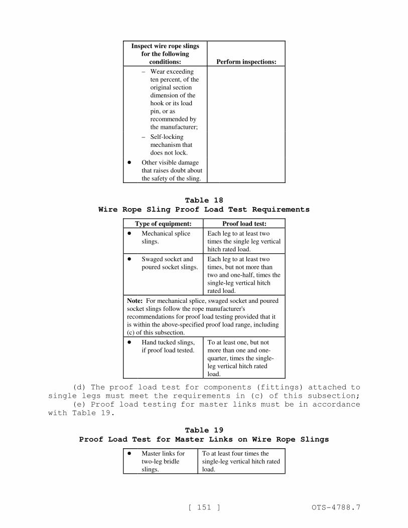
Inspect wire rope slings
for the following
conditions: Perform inspections:
[ 151 ] OTS-4788.7
– Wear exceeding
ten percent, of the
original section
dimension of the
hook or its load
pin, or as
recommended by
the manufacturer;
– Self-locking
mechanism that
does not lock.
! Other visible damage
that raises doubt about
the safety of the sling.
Table 18
Wire Rope Sling Proof Load Test Requirements
Type of equipment: Proof load test:
! Mechanical splice
slings.
Each leg to at least two
times the single leg vertical
hitch rated load.
! Swaged socket and
poured socket slings.
Each leg to at least two
times, but not more than
two and one-half, times the
single-leg vertical hitch
rated load.
Note: For mechanical splice, swaged socket and poured
socket slings follow the rope manufacturer's
recommendations for proof load testing provided that it
is within the above-specified proof load range, including
(c) of this subsection.
! Hand tucked slings,
if proof load tested.
To at least one, but not
more than one and one-
quarter, times the single-
leg vertical hitch rated
load.
(d) The proof load test for components (fittings) attached to
single legs must meet the requirements in (c) of this subsection;
(e) Proof load testing for master links must be in accordance
with Table 19.
Table 19
Proof Load Test for Master Links on Wire Rope Slings
! Master links for
two-leg bridle
slings.
To at least four times the
single-leg vertical hitch rated
load.
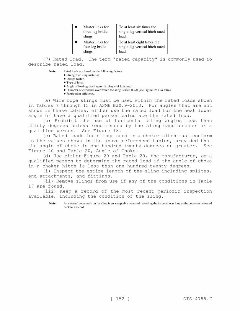
[ 152 ] OTS-4788.7
! Master links for
three-leg bridle
slings.
To at least six times the
single-leg vertical hitch rated
load.
! Master links for
four-leg bridle
slings.
To at least eight times the
single-leg vertical hitch rated
load.
(7) Rated load. The term "rated capacity" is commonly used to
describe rated load.
Note: Rated loads are based on the following factors:
! Strength of sling material;
! Design factor;
! Type of hitch;
! Angle of loading (see Figure 18, Angle of Loading);
! Diameter of curvature over which the sling is used (D/d) (see Figure 19, D/d ratio);
! Fabrication efficiency.
(a) Wire rope slings must be used within the rated loads shown
in Tables 7 through 15 in ASME B30.9-2010. For angles that are not
shown in these tables, either use the rated load for the next lower
angle or have a qualified person calculate the rated load.
(b) Prohibit the use of horizontal sling angles less than
thirty degrees unless recommended by the sling manufacturer or a
qualified person. See Figure 18.
(c) Rated loads for slings used in a choker hitch must conform
to the values shown in the above referenced tables, provided that
the angle of choke is one hundred twenty degrees or greater. See
Figure 20 and Table 20, Angle of Choke.
(d) Use either Figure 20 and Table 20, the manufacturer, or a
qualified person to determine the rated load if the angle of choke
in a choker hitch is less than one hundred twenty degrees.
(i) Inspect the entire length of the sling including splices,
end attachments, and fittings.
(ii) Remove slings from use if any of the conditions in Table
17 are found.
(iii) Keep a record of the most recent periodic inspection
available, including the condition of the sling.
Note: An external code mark on the sling is an acceptable means of recording the inspection as long as the code can be traced
back to a record.
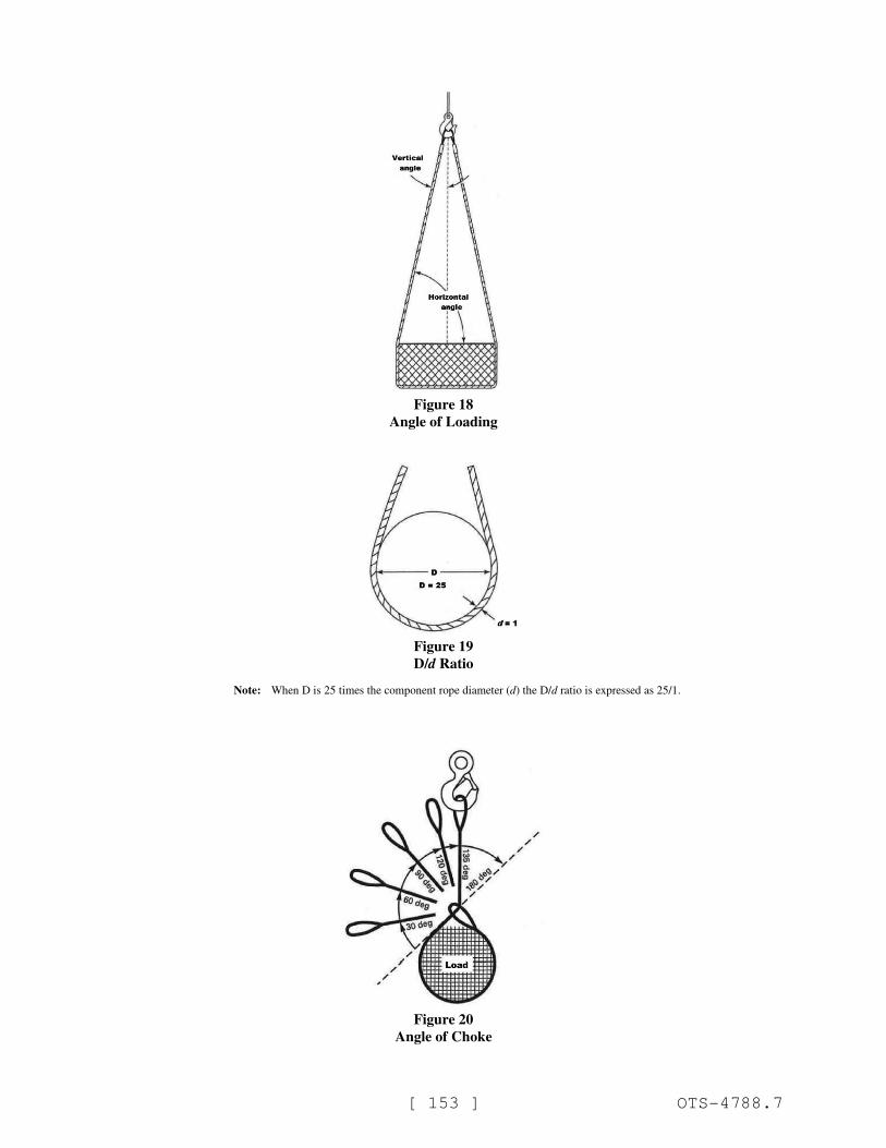
[ 153 ] OTS-4788.7
Figure 18
Angle of Loading
Figure 19
D/d Ratio
Note: When D is 25 times the component rope diameter (d) the D/d ratio is expressed as 25/1.
Figure 20
Angle of Choke
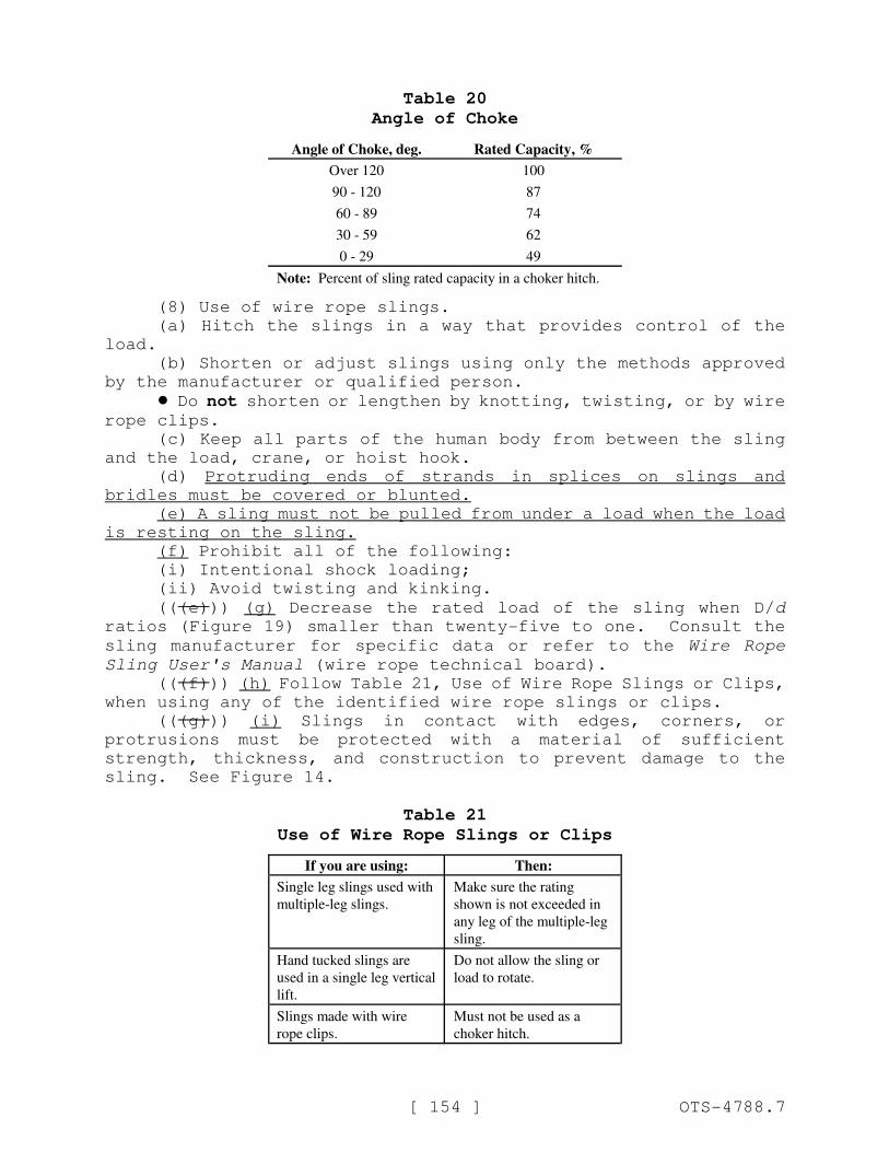
[ 154 ] OTS-4788.7
Table 20
Angle of Choke
Angle of Choke, deg. Rated Capacity, %
Over 120 100
90 - 120 87
60 - 89 74
30 - 59 62
0 - 29 49
Note: Percent of sling rated capacity in a choker hitch.
(8) Use of wire rope slings.
(a) Hitch the slings in a way that provides control of the
load.
(b) Shorten or adjust slings using only the methods approved
by the manufacturer or qualified person.
! Do not shorten or lengthen by knotting, twisting, or by wirerope clips.
(c) Keep all parts of the human body from between the sling
and the load, crane, or hoist hook.
(d) Protruding ends of strands in splices on slings and
bridles must be covered or blunted.
(e) A sling must not be pulled from under a load when the load
is resting on the sling.
(f) Prohibit all of the following:
(i) Intentional shock loading;
(ii) Avoid twisting and kinking.
(((e))) (g) Decrease the rated load of the sling when D/d
ratios (Figure 19) smaller than twenty-five to one. Consult the
sling manufacturer for specific data or refer to the Wire Rope
Sling User's Manual (wire rope technical board).
(((f))) (h) Follow Table 21, Use of Wire Rope Slings or Clips,
when using any of the identified wire rope slings or clips.
(((g))) (i) Slings in contact with edges, corners, or
protrusions must be protected with a material of sufficient
strength, thickness, and construction to prevent damage to the
sling. See Figure 14.
Table 21
Use of Wire Rope Slings or Clips
If you are using: Then:
Single leg slings used with
multiple-leg slings.
Make sure the rating
shown is not exceeded in
any leg of the multiple-leg
sling.
Hand tucked slings are
used in a single leg vertical
lift.
Do not allow the sling or
load to rotate.
Slings made with wire
rope clips.
Must not be used as a
choker hitch.
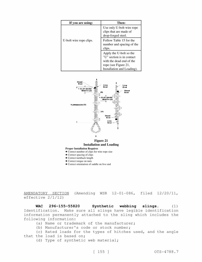
If you are using: Then:
[ 155 ] OTS-4788.7
Use only U-bolt wire rope
clips that are made of
drop-forged steel.
U-bolt wire rope clips. Follow Table 15 for the
number and spacing of the
clips.
Apply the U-bolt so the
"U" section is in contact
with the dead end of the
rope (see Figure 21,
Installation and Loading).
Figure 21
Installation and LoadingProper Installation Requires
! Correct number of clips for wire rope size
! Correct spacing of clips
! Correct turnback length
! Correct torque on nuts
! Correct orientation of saddle on live end
AMENDATORY SECTION (Amending WSR 12-01-086, filed 12/20/11,
effective 2/1/12)
WAC 296-155-55820 Synthetic webbing slings. (1)
Identification. Make sure all slings have legible identification
information permanently attached to the sling which includes the
following information:
(a) Name or trademark of the manufacturer;
(b) Manufacturer's code or stock number;
(c) Rated loads for the types of hitches used, and the angle
that the load is based on;
(d) Type of synthetic web material;
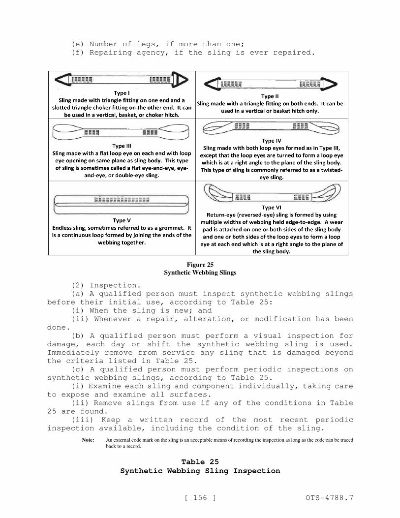
[ 156 ] OTS-4788.7
(e) Number of legs, if more than one;
(f) Repairing agency, if the sling is ever repaired.
Figure 25
Synthetic Webbing Slings
(2) Inspection.
(a) A qualified person must inspect synthetic webbing slings
before their initial use, according to Table 25:
(i) When the sling is new; and
(ii) Whenever a repair, alteration, or modification has been
done.
(b) A qualified person must perform a visual inspection for
damage, each day or shift the synthetic webbing sling is used.
Immediately remove from service any sling that is damaged beyond
the criteria listed in Table 25.
(c) A qualified person must perform periodic inspections on
synthetic webbing slings, according to Table 25.
(i) Examine each sling and component individually, taking care
to expose and examine all surfaces.
(ii) Remove slings from use if any of the conditions in Table
25 are found.
(iii) Keep a written record of the most recent periodic
inspection available, including the condition of the sling.
Note: An external code mark on the sling is an acceptable means of recording the inspection as long as the code can be traced
back to a record.
Table 25
Synthetic Webbing Sling Inspection

[ 157 ] OTS-4788.7
Inspect synthetic webbing
slings for the following
conditions: Perform inspections:
! Missing or illegible sling
identification;
! Acid or caustic burns; ! At least once a
year for slings in
normal service;
! Melting or charring on
any part of the sling;
! At least once a
quarter for slings
in severe service;
! Holes, tears, cuts or
snags;
! As recommended
by a qualified
person for slings in
special service.
! Broken or worn stitching
in load bearing splices;
! Excessive abrasive wear;
! Knots in any part of the
sling;
! Discoloration, brittle
fibers, and hard or stiff
areas that may indicate
chemical or
ultraviolet/sunlight
damage;
! Fittings that are pitted,
corroded, cracked, bent,
twisted, gouged or
broken;
! Hooks that have any of
the following conditions:
– Any visibly apparent
bend or twist from
the plane of the
unbent hook;
– Any distortion
causing an increase
in throat opening
five percent, not to
exceed one-quarter
inch, or as
recommended by the
manufacturer;
– Wear exceeding ten
percent, of the
original section
dimension of the
hook or its load pin,
or as recommended
by the manufacturer;
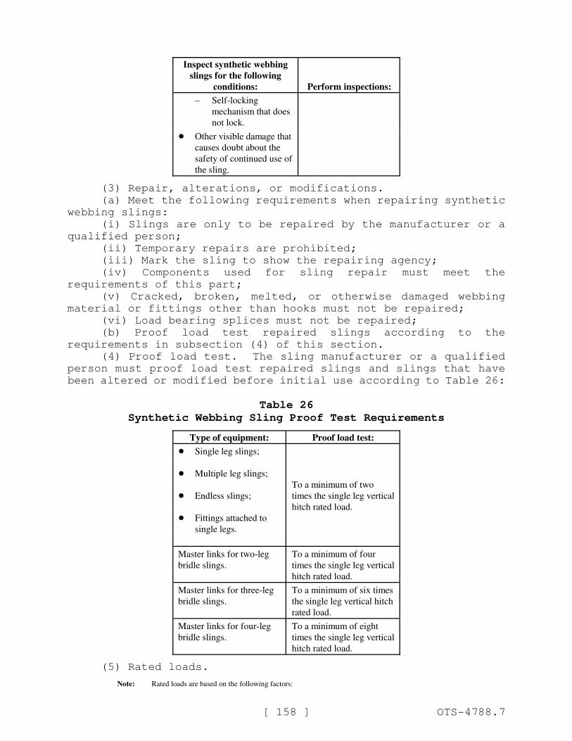
Inspect synthetic webbing
slings for the following
conditions: Perform inspections:
[ 158 ] OTS-4788.7
– Self-locking
mechanism that does
not lock.
! Other visible damage that
causes doubt about the
safety of continued use of
the sling.
(3) Repair, alterations, or modifications.
(a) Meet the following requirements when repairing synthetic
webbing slings:
(i) Slings are only to be repaired by the manufacturer or a
qualified person;
(ii) Temporary repairs are prohibited;
(iii) Mark the sling to show the repairing agency;
(iv) Components used for sling repair must meet the
requirements of this part;
(v) Cracked, broken, melted, or otherwise damaged webbing
material or fittings other than hooks must not be repaired;
(vi) Load bearing splices must not be repaired;
(b) Proof load test repaired slings according to the
requirements in subsection (4) of this section.
(4) Proof load test. The sling manufacturer or a qualified
person must proof load test repaired slings and slings that have
been altered or modified before initial use according to Table 26:
Table 26
Synthetic Webbing Sling Proof Test Requirements
Type of equipment: Proof load test:
!
!
!
!
Single leg slings;
Multiple leg slings;
Endless slings;
Fittings attached to
single legs.
To a minimum of two
times the single leg vertical
hitch rated load.
Master links for two-leg
bridle slings.
To a minimum of four
times the single leg vertical
hitch rated load.
Master links for three-leg
bridle slings.
To a minimum of six times
the single leg vertical hitch
rated load.
Master links for four-leg
bridle slings.
To a minimum of eight
times the single leg vertical
hitch rated load.
(5) Rated loads.
Note: Rated loads are based on the following factors:
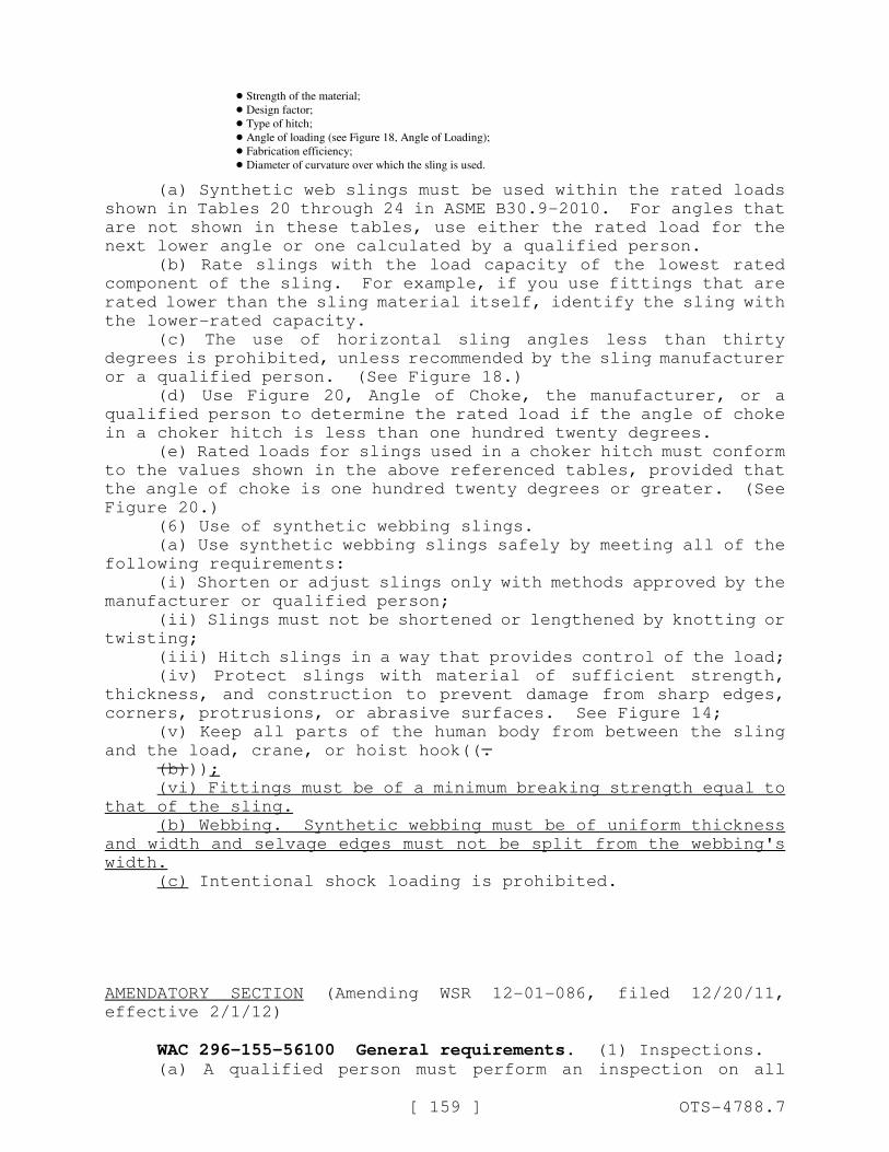
[ 159 ] OTS-4788.7
! Strength of the material;
! Design factor;
! Type of hitch;
! Angle of loading (see Figure 18, Angle of Loading);
! Fabrication efficiency;
! Diameter of curvature over which the sling is used.
(a) Synthetic web slings must be used within the rated loads
shown in Tables 20 through 24 in ASME B30.9-2010. For angles that
are not shown in these tables, use either the rated load for the
next lower angle or one calculated by a qualified person.
(b) Rate slings with the load capacity of the lowest rated
component of the sling. For example, if you use fittings that are
rated lower than the sling material itself, identify the sling with
the lower-rated capacity.
(c) The use of horizontal sling angles less than thirty
degrees is prohibited, unless recommended by the sling manufacturer
or a qualified person. (See Figure 18.)
(d) Use Figure 20, Angle of Choke, the manufacturer, or a
qualified person to determine the rated load if the angle of choke
in a choker hitch is less than one hundred twenty degrees.
(e) Rated loads for slings used in a choker hitch must conform
to the values shown in the above referenced tables, provided that
the angle of choke is one hundred twenty degrees or greater. (See
Figure 20.)
(6) Use of synthetic webbing slings.
(a) Use synthetic webbing slings safely by meeting all of the
following requirements:
(i) Shorten or adjust slings only with methods approved by the
manufacturer or qualified person;
(ii) Slings must not be shortened or lengthened by knotting or
twisting;
(iii) Hitch slings in a way that provides control of the load;
(iv) Protect slings with material of sufficient strength,
thickness, and construction to prevent damage from sharp edges,
corners, protrusions, or abrasive surfaces. See Figure 14;
(v) Keep all parts of the human body from between the sling
and the load, crane, or hoist hook((.
(b)));
(vi) Fittings must be of a minimum breaking strength equal to
that of the sling.
(b) Webbing. Synthetic webbing must be of uniform thickness
and width and selvage edges must not be split from the webbing's
width.
(c) Intentional shock loading is prohibited.
AMENDATORY SECTION (Amending WSR 12-01-086, filed 12/20/11,
effective 2/1/12)
WAC 296-155-56100 General requirements. (1) Inspections.(a) A qualified person must perform an inspection on all
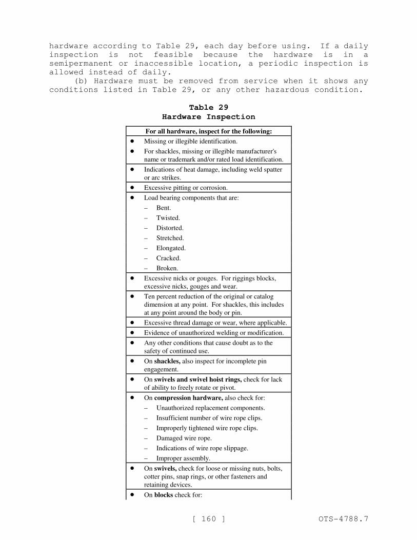
[ 160 ] OTS-4788.7
hardware according to Table 29, each day before using. If a daily
inspection is not feasible because the hardware is in a
semipermanent or inaccessible location, a periodic inspection is
allowed instead of daily.
(b) Hardware must be removed from service when it shows any
conditions listed in Table 29, or any other hazardous condition.
Table 29
Hardware Inspection
For all hardware, inspect for the following:
! Missing or illegible identification.
! For shackles, missing or illegible manufacturer's
name or trademark and/or rated load identification.
! Indications of heat damage, including weld spatter
or arc strikes.
! Excessive pitting or corrosion.
! Load bearing components that are:
– Bent.
– Twisted.
– Distorted.
– Stretched.
– Elongated.
– Cracked.
– Broken.
! Excessive nicks or gouges. For riggings blocks,
excessive nicks, gouges and wear.
! Ten percent reduction of the original or catalog
dimension at any point. For shackles, this includes
at any point around the body or pin.
! Excessive thread damage or wear, where applicable.
! Evidence of unauthorized welding or modification.
! Any other conditions that cause doubt as to the
safety of continued use.
! On shackles, also inspect for incomplete pin
engagement.
! On swivels and swivel hoist rings, check for lack
of ability to freely rotate or pivot.
! On compression hardware, also check for:
– Unauthorized replacement components.
– Insufficient number of wire rope clips.
– Improperly tightened wire rope clips.
– Damaged wire rope.
– Indications of wire rope slippage.
– Improper assembly.
! On swivels, check for loose or missing nuts, bolts,
cotter pins, snap rings, or other fasteners and
retaining devices.
! On blocks check for:
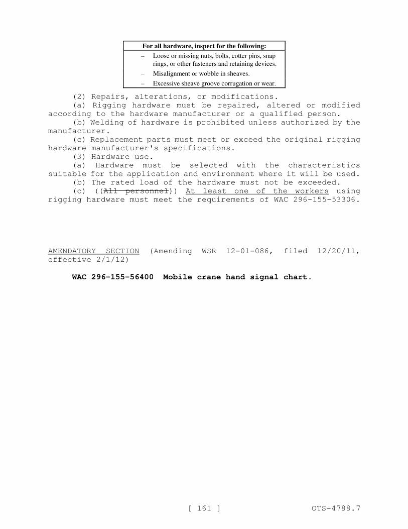
For all hardware, inspect for the following:
[ 161 ] OTS-4788.7
– Loose or missing nuts, bolts, cotter pins, snap
rings, or other fasteners and retaining devices.
– Misalignment or wobble in sheaves.
– Excessive sheave groove corrugation or wear.
(2) Repairs, alterations, or modifications.
(a) Rigging hardware must be repaired, altered or modified
according to the hardware manufacturer or a qualified person.
(b) Welding of hardware is prohibited unless authorized by the
manufacturer.
(c) Replacement parts must meet or exceed the original rigging
hardware manufacturer's specifications.
(3) Hardware use.
(a) Hardware must be selected with the characteristics
suitable for the application and environment where it will be used.
(b) The rated load of the hardware must not be exceeded.
(c) ((All personnel)) At least one of the workers using
rigging hardware must meet the requirements of WAC 296-155-53306.
AMENDATORY SECTION (Amending WSR 12-01-086, filed 12/20/11,
effective 2/1/12)
WAC 296-155-56400 Mobile crane hand signal chart.
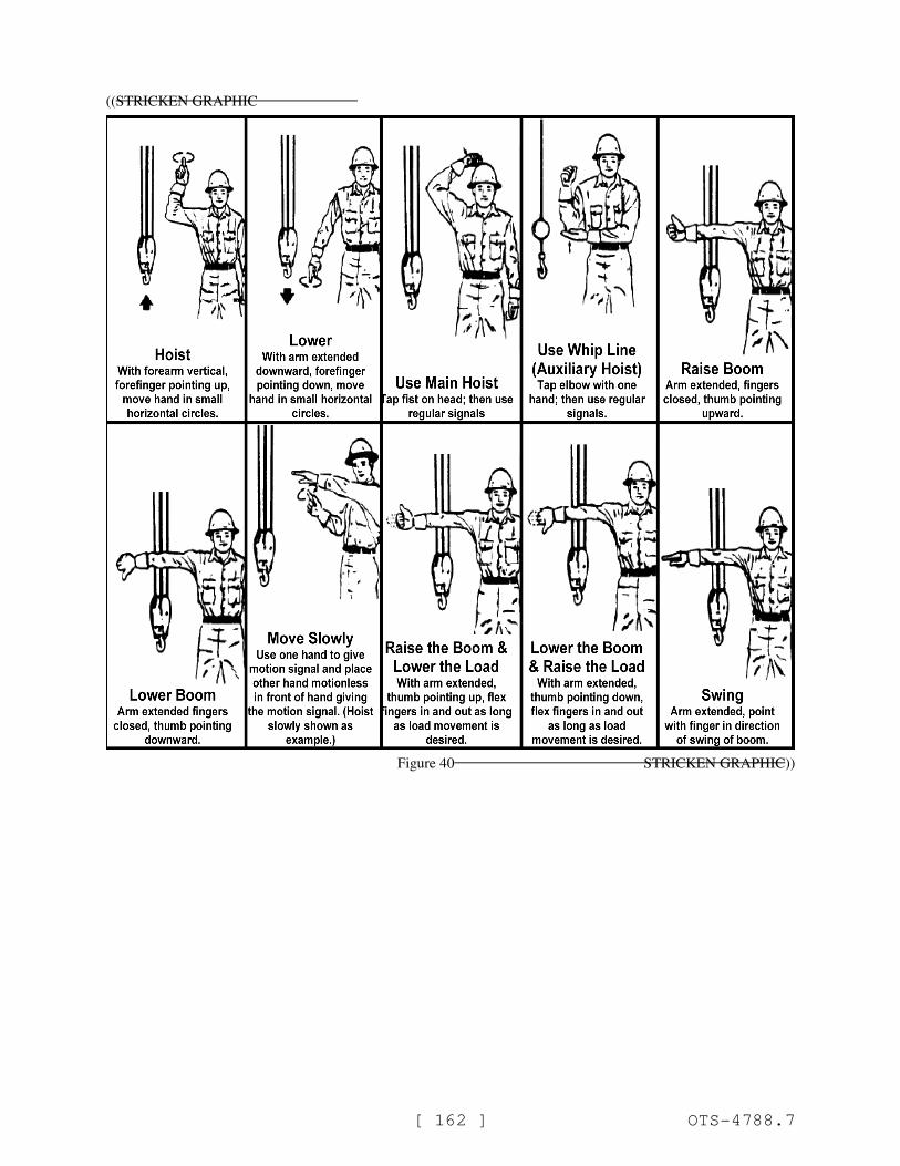
[ 162 ] OTS-4788.7
((STRICKEN GRAPHIC
Figure 40 STRICKEN GRAPHIC))
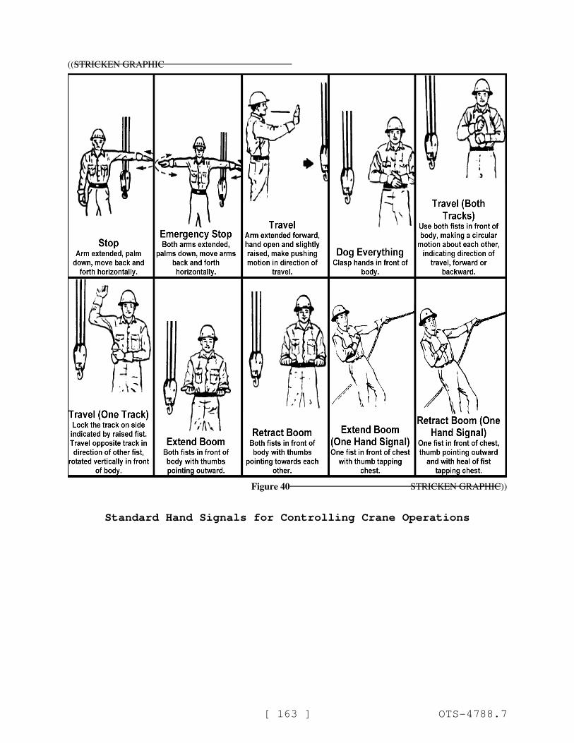
[ 163 ] OTS-4788.7
((STRICKEN GRAPHIC
Figure 40 STRICKEN GRAPHIC))
Standard Hand Signals for Controlling Crane Operations
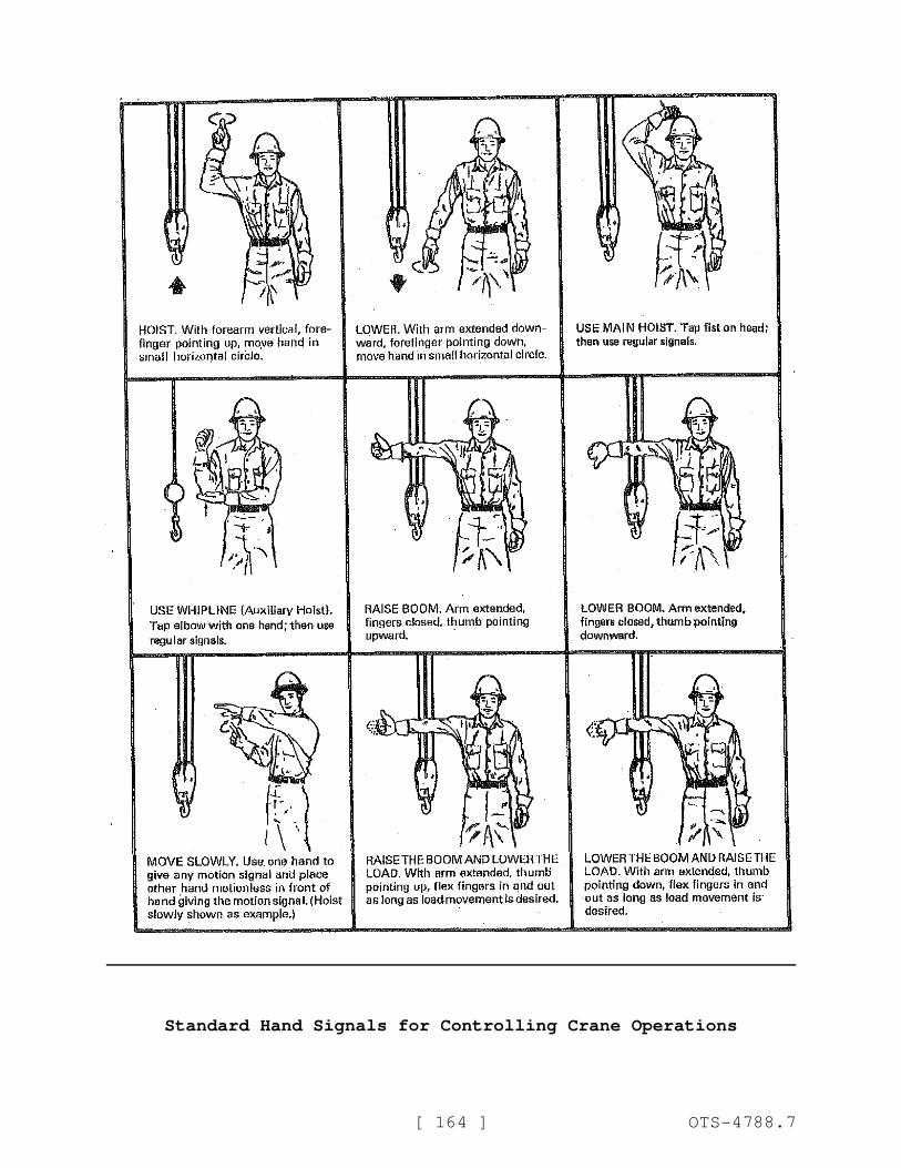
[ 164 ] OTS-4788.7
Standard Hand Signals for Controlling Crane Operations
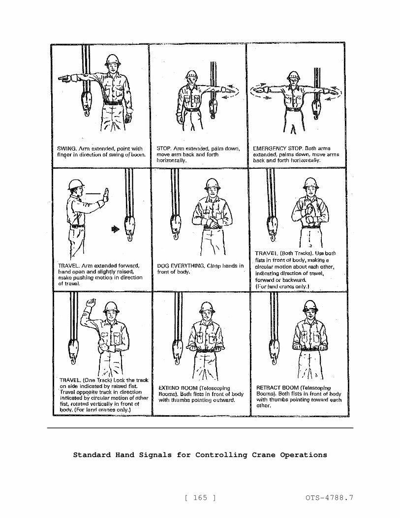
[ 165 ] OTS-4788.7
Standard Hand Signals for Controlling Crane Operations
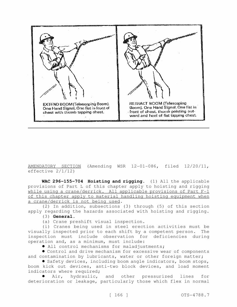
[ 166 ] OTS-4788.7
AMENDATORY SECTION (Amending WSR 12-01-086, filed 12/20/11,
effective 2/1/12)
WAC 296-155-704 Hoisting and rigging. (1) All the applicableprovisions of Part L of this chapter apply to hoisting and rigging
while using a crane/derrick. All applicable provisions of Part F-1
of this chapter apply to material handling hoisting equipment when
a crane/derrick is not being used.
(2) In addition, subsections (3) through (5) of this section
apply regarding the hazards associated with hoisting and rigging.
(3) General.(a) Crane preshift visual inspection.
(i) Cranes being used in steel erection activities must be
visually inspected prior to each shift by a competent person. The
inspection must include observation for deficiencies during
operation and, as a minimum, must include:
! All control mechanisms for maladjustments;
! Control and drive mechanism for excessive wear of components
and contamination by lubricants, water or other foreign matter;
! Safety devices, including boom angle indicators, boom stops,
boom kick out devices, anti-two block devices, and load moment
indicators where required;
! Air, hydraulic, and other pressurized lines for
deterioration or leakage, particularly those which flex in normal
[ 167 ] OTS-4788.7
operation;
! Hooks and latches for deformation, chemical damage, cracks,
or wear;
! Wire rope reeving for compliance with hoisting equipment
manufacturer's specifications;
! Electrical apparatus for malfunctioning, signs of excessive
deterioration, dirt, or moisture accumulation;
! Hydraulic system for proper fluid level;
! Tires for proper inflation and condition;
! Ground conditions around the hoisting equipment for proper
support, including ground settling under and around outriggers,
ground water accumulation, or similar conditions;
! The hoisting equipment for level position; and
! The hoisting equipment for level position after each move
and setup.
(ii) If any deficiency is identified, an immediate
determination must be made by the competent person if the
deficiency constitutes a hazard.
(iii) If the deficiency constitutes a hazard, the hoisting
equipment must be removed from service until the deficiency has
been corrected.
(iv) The operator is responsible for those operations under
their direct control. Whenever there is any doubt as to safety,
the operator must have the authority to stop and refuse to handle
loads until safety has been assured.
(b) A qualified ((person)) rigger (a rigger who is also a
qualified person) must inspect the rigging prior to each shift ((in
accordance with WAC 296-155-556 through 296-155-56220)).
(c) The headache ball, hook or load must not be used to
transport personnel, except as provided in (d) of this subsection.
(d) Cranes or derricks may be used to hoist employees on a
personnel platform when work under this part is being conducted if
all the applicable provisions of Part L of this chapter are met.
(e) Safety latches on hooks must not be deactivated or made
inoperable except:
(i) When a qualified rigger has determined that the hoisting
and placing of purlins and single joists can be performed more
safely by doing so; or
(ii) When equivalent protection is provided in a site-specific
erection plan.
(4) Working under loads.(a) Routes for suspended loads must be preplanned to ensure
that no employee works directly below a suspended load except when:
(i) Engaged in the initial connection of the steel; or
(ii) Necessary for the hooking or unhooking of the load.
(b) Whenever workers are within the fall zone and hooking,
unhooking, or guiding a load, or doing the initial connection of a
load to a component or structure (WAC 296-155-53400 (43)(c)), the
following criteria must be met:
(i) Materials being hoisted must be rigged to prevent
unintentional displacement;
(ii) Hooks with self-closing safety latches or their
equivalent must be used to prevent components from slipping out of
[ 168 ] OTS-4788.7
the hook; and
(iii) All loads must be rigged by a qualified rigger.
(5) Multiple lift rigging procedure.(a) A multiple lift must only be performed if the following
criteria are met:
! A multiple lift rigging assembly is used;
! A multiple lift is only permitted when specifically within
the manufacturer's specifications and limitations;
! A maximum of five members are hoisted per lift;
Exception: Bundles of decking must not be lifted using the multiple lift rigging procedure, even though they meet the
definition of structural members in WAC 296-155-702.
! Only beams and similar structural members are lifted; and
! All employees engaged in the multiple lift have been trained
in these procedures in accordance with WAC 296-155-717 (3)(a).
(b) Components of the multiple lift rigging assembly must be
specifically designed and assembled with a maximum capacity for
total assembly and for each individual attachment point. This
capacity, certified by the manufacturer or a qualified rigger, must
be based on the manufacturer's specifications with a five to one
safety factor for all components.
(c) The total load must not exceed:
! The rated capacity of the hoisting equipment specified in
the hoisting equipment load charts; and
! The rigging capacity specified in the rigging-rating chart.
(d) The multiple lift rigging assembly must be rigged with
members:
! Attached at their center of gravity and maintained
reasonably level;
! Rigged from top down; and
! Rigged at least seven feet (2.1 m) apart.
(e) The members on the multiple lift rigging assembly must be
set from the bottom up.
(f) Controlled load lowering must be used whenever the load is
over the connectors.
REPEALER
The following section of the Washington Administrative Code
is repealed:
WAC 296-155-329 Qualified person--Rigging.