Embed Size (px)
Citation preview
Part Design & Sketcher
NATIONAL INSTITUTE FOR AVIATION RESEARCHWichita State University
Revision 5.14Copyright 2005. All rights reserved.
www.cadcamlab.org

None of this material may be reproduced, used or disclosed, in part or in whole, without the expressed written permission of:
National Institute for Aviation ResearchWichita State University
Wichita, KS
Copyright 2005. All rights reserved.
www.cadcamlab.org

CATIA Part Design & Sketcher CATIA® V5R14
Table of Contents, Page i© Wichita State University
TABLE OF CONTENTS
Introduction . . . . . . . . . . . . . . . . . . . . . . . . . . . . . . . . . . . . . . . . . . . . . . . . . . . . . . . . . . . . . . 1Manual Format . . . . . . . . . . . . . . . . . . . . . . . . . . . . . . . . . . . . . . . . . . . . . . . . . . . . . . 2Part Design & Sketcher . . . . . . . . . . . . . . . . . . . . . . . . . . . . . . . . . . . . . . . . . . . . . . . 3Log on/off procedures for Windows . . . . . . . . . . . . . . . . . . . . . . . . . . . . . . . . . . . . . 4
To log on . . . . . . . . . . . . . . . . . . . . . . . . . . . . . . . . . . . . . . . . . . . . . . . . . . . . 4To logoff . . . . . . . . . . . . . . . . . . . . . . . . . . . . . . . . . . . . . . . . . . . . . . . . . . . . 5
CATIA Version 5 Screen . . . . . . . . . . . . . . . . . . . . . . . . . . . . . . . . . . . . . . . . . . . . . . 7Part Design Screen . . . . . . . . . . . . . . . . . . . . . . . . . . . . . . . . . . . . . . . . . . . . . . . . . . . 8Pull-down Menus . . . . . . . . . . . . . . . . . . . . . . . . . . . . . . . . . . . . . . . . . . . . . . . . . . . . 9
Start . . . . . . . . . . . . . . . . . . . . . . . . . . . . . . . . . . . . . . . . . . . . . . . . . . . . . . . . 9File . . . . . . . . . . . . . . . . . . . . . . . . . . . . . . . . . . . . . . . . . . . . . . . . . . . . . . . . 10Edit . . . . . . . . . . . . . . . . . . . . . . . . . . . . . . . . . . . . . . . . . . . . . . . . . . . . . . . . 11View . . . . . . . . . . . . . . . . . . . . . . . . . . . . . . . . . . . . . . . . . . . . . . . . . . . . . . . 13Insert . . . . . . . . . . . . . . . . . . . . . . . . . . . . . . . . . . . . . . . . . . . . . . . . . . . . . . . 17Tools . . . . . . . . . . . . . . . . . . . . . . . . . . . . . . . . . . . . . . . . . . . . . . . . . . . . . . 19Window . . . . . . . . . . . . . . . . . . . . . . . . . . . . . . . . . . . . . . . . . . . . . . . . . . . . 24Help . . . . . . . . . . . . . . . . . . . . . . . . . . . . . . . . . . . . . . . . . . . . . . . . . . . . . . . 25
Bottom Toolbar in Part Design . . . . . . . . . . . . . . . . . . . . . . . . . . . . . . . . . . . . . . . . 26Part Design Workbench . . . . . . . . . . . . . . . . . . . . . . . . . . . . . . . . . . . . . . . . . . . . . . 28Sketcher Screen . . . . . . . . . . . . . . . . . . . . . . . . . . . . . . . . . . . . . . . . . . . . . . . . . . . . 30Sketcher changes . . . . . . . . . . . . . . . . . . . . . . . . . . . . . . . . . . . . . . . . . . . . . . . . . . . 31
Bottom Toolbar . . . . . . . . . . . . . . . . . . . . . . . . . . . . . . . . . . . . . . . . . . . . . . 31Sketch tools . . . . . . . . . . . . . . . . . . . . . . . . . . . . . . . . . . . . . . . . . . . . . . . . . 32
Sketcher Workbench . . . . . . . . . . . . . . . . . . . . . . . . . . . . . . . . . . . . . . . . . . . . . . . . 33Working with Documents . . . . . . . . . . . . . . . . . . . . . . . . . . . . . . . . . . . . . . . . . . . . 35
Types of documents . . . . . . . . . . . . . . . . . . . . . . . . . . . . . . . . . . . . . . . . . . . 35Creating a new document . . . . . . . . . . . . . . . . . . . . . . . . . . . . . . . . . . . . . . . 35Opening an existing document . . . . . . . . . . . . . . . . . . . . . . . . . . . . . . . . . . . 36Saving a document . . . . . . . . . . . . . . . . . . . . . . . . . . . . . . . . . . . . . . . . . . . . 37Closing a document . . . . . . . . . . . . . . . . . . . . . . . . . . . . . . . . . . . . . . . . . . . 38
Manipulating the Display . . . . . . . . . . . . . . . . . . . . . . . . . . . . . . . . . . . . . . . . . . . . . 39Three button mouse . . . . . . . . . . . . . . . . . . . . . . . . . . . . . . . . . . . . . . . . . . . 39Two button mouse . . . . . . . . . . . . . . . . . . . . . . . . . . . . . . . . . . . . . . . . . . . . 39SpaceBall or SpaceMouse . . . . . . . . . . . . . . . . . . . . . . . . . . . . . . . . . . . . . . 39Keyboard . . . . . . . . . . . . . . . . . . . . . . . . . . . . . . . . . . . . . . . . . . . . . . . . . . . 40
Keyboard Shortcuts . . . . . . . . . . . . . . . . . . . . . . . . . . . . . . . . . . . . . . . . . . . . . . . . . 41
CATIA Part Design & Sketcher CATIA® V5R14
Table of Contents, Page ii ©Wichita State University
Basic Sketcher . . . . . . . . . . . . . . . . . . . . . . . . . . . . . . . . . . . . . . . . . . . . . . . . . . . . . . . . . . . 43Basic Shapes . . . . . . . . . . . . . . . . . . . . . . . . . . . . . . . . . . . . . . . . . . . . . . . . . . . . . . 43
Creating a new part with a new sketch . . . . . . . . . . . . . . . . . . . . . . . . . . . . 44Saving and closing the part . . . . . . . . . . . . . . . . . . . . . . . . . . . . . . . . . . . . . 45Rectangle . . . . . . . . . . . . . . . . . . . . . . . . . . . . . . . . . . . . . . . . . . . . . . . . . . . 46Oriented Rectangle . . . . . . . . . . . . . . . . . . . . . . . . . . . . . . . . . . . . . . . . . . . . 47Parallelogram . . . . . . . . . . . . . . . . . . . . . . . . . . . . . . . . . . . . . . . . . . . . . . . . 48Elongated Hole . . . . . . . . . . . . . . . . . . . . . . . . . . . . . . . . . . . . . . . . . . . . . . . 49Cylindrical Elongated Hole . . . . . . . . . . . . . . . . . . . . . . . . . . . . . . . . . . . . . 50Keyhole . . . . . . . . . . . . . . . . . . . . . . . . . . . . . . . . . . . . . . . . . . . . . . . . . . . . 52Hexagon . . . . . . . . . . . . . . . . . . . . . . . . . . . . . . . . . . . . . . . . . . . . . . . . . . . . 53Centered Rectangle . . . . . . . . . . . . . . . . . . . . . . . . . . . . . . . . . . . . . . . . . . . 54Centered Parallelogram . . . . . . . . . . . . . . . . . . . . . . . . . . . . . . . . . . . . . . . . 55Circle . . . . . . . . . . . . . . . . . . . . . . . . . . . . . . . . . . . . . . . . . . . . . . . . . . . . . . 56Circle through 3 points . . . . . . . . . . . . . . . . . . . . . . . . . . . . . . . . . . . . . . . . . 57Circle with Cartesian coordinates . . . . . . . . . . . . . . . . . . . . . . . . . . . . . . . . 58Circle tangent to 3 elements . . . . . . . . . . . . . . . . . . . . . . . . . . . . . . . . . . . . . 59Arc through 3 points . . . . . . . . . . . . . . . . . . . . . . . . . . . . . . . . . . . . . . . . . . 60Arc through 3 points with limits . . . . . . . . . . . . . . . . . . . . . . . . . . . . . . . . . 61Arc . . . . . . . . . . . . . . . . . . . . . . . . . . . . . . . . . . . . . . . . . . . . . . . . . . . . . . . . 62Spline . . . . . . . . . . . . . . . . . . . . . . . . . . . . . . . . . . . . . . . . . . . . . . . . . . . . . . 63Connect Curve . . . . . . . . . . . . . . . . . . . . . . . . . . . . . . . . . . . . . . . . . . . . . . . 65Ellipse . . . . . . . . . . . . . . . . . . . . . . . . . . . . . . . . . . . . . . . . . . . . . . . . . . . . . 67Parabola . . . . . . . . . . . . . . . . . . . . . . . . . . . . . . . . . . . . . . . . . . . . . . . . . . . . 68Hyperbola . . . . . . . . . . . . . . . . . . . . . . . . . . . . . . . . . . . . . . . . . . . . . . . . . . . 69Conic . . . . . . . . . . . . . . . . . . . . . . . . . . . . . . . . . . . . . . . . . . . . . . . . . . . . . . 70Line . . . . . . . . . . . . . . . . . . . . . . . . . . . . . . . . . . . . . . . . . . . . . . . . . . . . . . . 75Infinite Line . . . . . . . . . . . . . . . . . . . . . . . . . . . . . . . . . . . . . . . . . . . . . . . . . 76Bi-tangent Line . . . . . . . . . . . . . . . . . . . . . . . . . . . . . . . . . . . . . . . . . . . . . . 77Bisect Line . . . . . . . . . . . . . . . . . . . . . . . . . . . . . . . . . . . . . . . . . . . . . . . . . . 79Normal Line to Curve . . . . . . . . . . . . . . . . . . . . . . . . . . . . . . . . . . . . . . . . . 80Axis line . . . . . . . . . . . . . . . . . . . . . . . . . . . . . . . . . . . . . . . . . . . . . . . . . . . . 81Point by clicking . . . . . . . . . . . . . . . . . . . . . . . . . . . . . . . . . . . . . . . . . . . . . 82Point by using coordinates . . . . . . . . . . . . . . . . . . . . . . . . . . . . . . . . . . . . . . 83Equidistant points . . . . . . . . . . . . . . . . . . . . . . . . . . . . . . . . . . . . . . . . . . . . 84Intersection Point . . . . . . . . . . . . . . . . . . . . . . . . . . . . . . . . . . . . . . . . . . . . . 86Projection Point . . . . . . . . . . . . . . . . . . . . . . . . . . . . . . . . . . . . . . . . . . . . . . 87
Profiles . . . . . . . . . . . . . . . . . . . . . . . . . . . . . . . . . . . . . . . . . . . . . . . . . . . . . . . . . . . 89Constraints . . . . . . . . . . . . . . . . . . . . . . . . . . . . . . . . . . . . . . . . . . . . . . . . . . . . . . . 106
Dimensional Constraints . . . . . . . . . . . . . . . . . . . . . . . . . . . . . . . . . . . . . . 106Geometrical Constraints . . . . . . . . . . . . . . . . . . . . . . . . . . . . . . . . . . . . . . . 106
Operations on profiles . . . . . . . . . . . . . . . . . . . . . . . . . . . . . . . . . . . . . . . . . . . . . . 153Corner . . . . . . . . . . . . . . . . . . . . . . . . . . . . . . . . . . . . . . . . . . . . . . . . . . . . 153Chamfer . . . . . . . . . . . . . . . . . . . . . . . . . . . . . . . . . . . . . . . . . . . . . . . . . . . 158Trim and Break . . . . . . . . . . . . . . . . . . . . . . . . . . . . . . . . . . . . . . . . . . . . . 162
Specification Tree . . . . . . . . . . . . . . . . . . . . . . . . . . . . . . . . . . . . . . . . . . . . . . . . . 167Hide/Show . . . . . . . . . . . . . . . . . . . . . . . . . . . . . . . . . . . . . . . . . . . . . . . . . . . . . . . 169
CATIA Part Design & Sketcher CATIA® V5R14
Table of Contents, Page iii© Wichita State University
Basic Part Design . . . . . . . . . . . . . . . . . . . . . . . . . . . . . . . . . . . . . . . . . . . . . . . . . . . . . . . . 173Basic Shapes . . . . . . . . . . . . . . . . . . . . . . . . . . . . . . . . . . . . . . . . . . . . . . . . . . . . . 173
Pad . . . . . . . . . . . . . . . . . . . . . . . . . . . . . . . . . . . . . . . . . . . . . . . . . . . . . . . 174Pocket . . . . . . . . . . . . . . . . . . . . . . . . . . . . . . . . . . . . . . . . . . . . . . . . . . . . . 184Multiple Profiles . . . . . . . . . . . . . . . . . . . . . . . . . . . . . . . . . . . . . . . . . . . . 188Multi-Pad and Multi-Pocket . . . . . . . . . . . . . . . . . . . . . . . . . . . . . . . . . . . 190Shaft . . . . . . . . . . . . . . . . . . . . . . . . . . . . . . . . . . . . . . . . . . . . . . . . . . . . . . 193Groove . . . . . . . . . . . . . . . . . . . . . . . . . . . . . . . . . . . . . . . . . . . . . . . . . . . . 197Hole . . . . . . . . . . . . . . . . . . . . . . . . . . . . . . . . . . . . . . . . . . . . . . . . . . . . . . 201Rib . . . . . . . . . . . . . . . . . . . . . . . . . . . . . . . . . . . . . . . . . . . . . . . . . . . . . . . 214Slot . . . . . . . . . . . . . . . . . . . . . . . . . . . . . . . . . . . . . . . . . . . . . . . . . . . . . . . 217Combine . . . . . . . . . . . . . . . . . . . . . . . . . . . . . . . . . . . . . . . . . . . . . . . . . . . 219Stiffener . . . . . . . . . . . . . . . . . . . . . . . . . . . . . . . . . . . . . . . . . . . . . . . . . . . 221
Operations on Shapes . . . . . . . . . . . . . . . . . . . . . . . . . . . . . . . . . . . . . . . . . . . . . . . 224Fillet . . . . . . . . . . . . . . . . . . . . . . . . . . . . . . . . . . . . . . . . . . . . . . . . . . . . . . 224Chamfer . . . . . . . . . . . . . . . . . . . . . . . . . . . . . . . . . . . . . . . . . . . . . . . . . . . 242Draft Angle . . . . . . . . . . . . . . . . . . . . . . . . . . . . . . . . . . . . . . . . . . . . . . . . 244Shell . . . . . . . . . . . . . . . . . . . . . . . . . . . . . . . . . . . . . . . . . . . . . . . . . . . . . . 248Thickness . . . . . . . . . . . . . . . . . . . . . . . . . . . . . . . . . . . . . . . . . . . . . . . . . . 250Thread/Tap . . . . . . . . . . . . . . . . . . . . . . . . . . . . . . . . . . . . . . . . . . . . . . . . . 252Remove face . . . . . . . . . . . . . . . . . . . . . . . . . . . . . . . . . . . . . . . . . . . . . . . . 254Replace face . . . . . . . . . . . . . . . . . . . . . . . . . . . . . . . . . . . . . . . . . . . . . . . . 256Modifying values . . . . . . . . . . . . . . . . . . . . . . . . . . . . . . . . . . . . . . . . . . . . 258
Interfacing with Sketcher . . . . . . . . . . . . . . . . . . . . . . . . . . . . . . . . . . . . . . . . . . . . 263
Advanced Sketcher . . . . . . . . . . . . . . . . . . . . . . . . . . . . . . . . . . . . . . . . . . . . . . . . . . . . . . 2693-D Elements on Sketch Plane . . . . . . . . . . . . . . . . . . . . . . . . . . . . . . . . . . . . . . . . 269Construction Geometry . . . . . . . . . . . . . . . . . . . . . . . . . . . . . . . . . . . . . . . . . . . . . 275Advanced Constraints . . . . . . . . . . . . . . . . . . . . . . . . . . . . . . . . . . . . . . . . . . . . . . 277Sketch Transformations . . . . . . . . . . . . . . . . . . . . . . . . . . . . . . . . . . . . . . . . . . . . . 287Sketch Analysis . . . . . . . . . . . . . . . . . . . . . . . . . . . . . . . . . . . . . . . . . . . . . . . . . . . 297Sketch Visualization . . . . . . . . . . . . . . . . . . . . . . . . . . . . . . . . . . . . . . . . . . . . . . . 300
Advanced Part Design . . . . . . . . . . . . . . . . . . . . . . . . . . . . . . . . . . . . . . . . . . . . . . . . . . . . 303Part Transformations . . . . . . . . . . . . . . . . . . . . . . . . . . . . . . . . . . . . . . . . . . . . . . . 303Patterns . . . . . . . . . . . . . . . . . . . . . . . . . . . . . . . . . . . . . . . . . . . . . . . . . . . . . . . . . . 309Modifying Parts . . . . . . . . . . . . . . . . . . . . . . . . . . . . . . . . . . . . . . . . . . . . . . . . . . . 320Inserting Bodies and Boolean Operations . . . . . . . . . . . . . . . . . . . . . . . . . . . . . . . 334
Inserting Part Bodies . . . . . . . . . . . . . . . . . . . . . . . . . . . . . . . . . . . . . . . . . 334Boolean operations . . . . . . . . . . . . . . . . . . . . . . . . . . . . . . . . . . . . . . . . . . . 335
Part Design Multi-Sections Solids . . . . . . . . . . . . . . . . . . . . . . . . . . . . . . . . . . . . . 341Part Design Using Surfaces . . . . . . . . . . . . . . . . . . . . . . . . . . . . . . . . . . . . . . . . . . 343Annotations . . . . . . . . . . . . . . . . . . . . . . . . . . . . . . . . . . . . . . . . . . . . . . . . . . . . . . 348Applying Materials . . . . . . . . . . . . . . . . . . . . . . . . . . . . . . . . . . . . . . . . . . . . . . . . 351Delete Useless Elements . . . . . . . . . . . . . . . . . . . . . . . . . . . . . . . . . . . . . . . . . . . . 355
CATIA Part Design & Sketcher CATIA® V5R14
Table of Contents, Page iv ©Wichita State University
Problems . . . . . . . . . . . . . . . . . . . . . . . . . . . . . . . . . . . . . . . . . . . . . . . . . . . . . . . . . . . . . . 357Problem #1.0 . . . . . . . . . . . . . . . . . . . . . . . . . . . . . . . . . . . . . . . . . . . . . . . . . . . . . 357Problem #2.0 . . . . . . . . . . . . . . . . . . . . . . . . . . . . . . . . . . . . . . . . . . . . . . . . . . . . . 358Problem #3.0 . . . . . . . . . . . . . . . . . . . . . . . . . . . . . . . . . . . . . . . . . . . . . . . . . . . . . 359Problem #4.0 . . . . . . . . . . . . . . . . . . . . . . . . . . . . . . . . . . . . . . . . . . . . . . . . . . . . . 360Problem #5.0 . . . . . . . . . . . . . . . . . . . . . . . . . . . . . . . . . . . . . . . . . . . . . . . . . . . . . 361Problem #6.0 . . . . . . . . . . . . . . . . . . . . . . . . . . . . . . . . . . . . . . . . . . . . . . . . . . . . . 362Problem #7.0 . . . . . . . . . . . . . . . . . . . . . . . . . . . . . . . . . . . . . . . . . . . . . . . . . . . . . 364Problem #8.0 . . . . . . . . . . . . . . . . . . . . . . . . . . . . . . . . . . . . . . . . . . . . . . . . . . . . . 365Problem #9.0 . . . . . . . . . . . . . . . . . . . . . . . . . . . . . . . . . . . . . . . . . . . . . . . . . . . . . 366Problem #10.0 . . . . . . . . . . . . . . . . . . . . . . . . . . . . . . . . . . . . . . . . . . . . . . . . . . . . 367Problem #11.0 . . . . . . . . . . . . . . . . . . . . . . . . . . . . . . . . . . . . . . . . . . . . . . . . . . . . 368Problem #12.0 . . . . . . . . . . . . . . . . . . . . . . . . . . . . . . . . . . . . . . . . . . . . . . . . . . . . 369Problem #13.0 . . . . . . . . . . . . . . . . . . . . . . . . . . . . . . . . . . . . . . . . . . . . . . . . . . . . 370Problem #14.0 . . . . . . . . . . . . . . . . . . . . . . . . . . . . . . . . . . . . . . . . . . . . . . . . . . . . 371Problem #15.0 . . . . . . . . . . . . . . . . . . . . . . . . . . . . . . . . . . . . . . . . . . . . . . . . . . . . 372Problem #16.0 . . . . . . . . . . . . . . . . . . . . . . . . . . . . . . . . . . . . . . . . . . . . . . . . . . . . 373Problem #17.0 . . . . . . . . . . . . . . . . . . . . . . . . . . . . . . . . . . . . . . . . . . . . . . . . . . . . 374Problem #18.0 . . . . . . . . . . . . . . . . . . . . . . . . . . . . . . . . . . . . . . . . . . . . . . . . . . . . 375Problem #19.0 . . . . . . . . . . . . . . . . . . . . . . . . . . . . . . . . . . . . . . . . . . . . . . . . . . . . 376Problem #20.0 . . . . . . . . . . . . . . . . . . . . . . . . . . . . . . . . . . . . . . . . . . . . . . . . . . . . 377Problem #21.0 . . . . . . . . . . . . . . . . . . . . . . . . . . . . . . . . . . . . . . . . . . . . . . . . . . . . 378Problem #22.0 . . . . . . . . . . . . . . . . . . . . . . . . . . . . . . . . . . . . . . . . . . . . . . . . . . . . 379Problem #23.0 . . . . . . . . . . . . . . . . . . . . . . . . . . . . . . . . . . . . . . . . . . . . . . . . . . . . 380Problem #24.0 . . . . . . . . . . . . . . . . . . . . . . . . . . . . . . . . . . . . . . . . . . . . . . . . . . . . 381Problem #25.0 . . . . . . . . . . . . . . . . . . . . . . . . . . . . . . . . . . . . . . . . . . . . . . . . . . . . 382Problem #26.0 . . . . . . . . . . . . . . . . . . . . . . . . . . . . . . . . . . . . . . . . . . . . . . . . . . . . 383Problem #27.0 . . . . . . . . . . . . . . . . . . . . . . . . . . . . . . . . . . . . . . . . . . . . . . . . . . . . 384
Appendix A . . . . . . . . . . . . . . . . . . . . . . . . . . . . . . . . . . . . . . . . . . . . . . . . . . . . . . . . . . . . 385Customize - Start Menu . . . . . . . . . . . . . . . . . . . . . . . . . . . . . . . . . . . . . . . . . . . . . 385Customize - User Workbenches . . . . . . . . . . . . . . . . . . . . . . . . . . . . . . . . . . . . . . . 386Customize - Toolbars . . . . . . . . . . . . . . . . . . . . . . . . . . . . . . . . . . . . . . . . . . . . . . . 386Customize - Commands . . . . . . . . . . . . . . . . . . . . . . . . . . . . . . . . . . . . . . . . . . . . . 387Customize - Options . . . . . . . . . . . . . . . . . . . . . . . . . . . . . . . . . . . . . . . . . . . . . . . 387
Appendix B . . . . . . . . . . . . . . . . . . . . . . . . . . . . . . . . . . . . . . . . . . . . . . . . . . . . . . . . . . . . 389General - Performances . . . . . . . . . . . . . . . . . . . . . . . . . . . . . . . . . . . . . . . . . . . . . 389General - Display - Tree Appearance . . . . . . . . . . . . . . . . . . . . . . . . . . . . . . . . . . . 390General - Display - Tree Manipulation . . . . . . . . . . . . . . . . . . . . . . . . . . . . . . . . . 391General - Display - Visualization . . . . . . . . . . . . . . . . . . . . . . . . . . . . . . . . . . . . . . 392General - Parameters and Measure - Units . . . . . . . . . . . . . . . . . . . . . . . . . . . . . . 393General - Parameters and Measure - Symbols . . . . . . . . . . . . . . . . . . . . . . . . . . . . 394Infrastructure - Product Structure - Product Structure . . . . . . . . . . . . . . . . . . . . . . 395Infrastructure - Part Infrastructure - General . . . . . . . . . . . . . . . . . . . . . . . . . . . . . 396Infrastructure - Part Infrastructure - Display . . . . . . . . . . . . . . . . . . . . . . . . . . . . . 397Infrastructure - Part Infrastructure - Part Document . . . . . . . . . . . . . . . . . . . . . . . 398Mechanical Design - Sketcher . . . . . . . . . . . . . . . . . . . . . . . . . . . . . . . . . . . . . . . . 399
CATIA Part Design & Sketcher CATIA® V5R14
Table of Contents, Page v© Wichita State University
Appendix C . . . . . . . . . . . . . . . . . . . . . . . . . . . . . . . . . . . . . . . . . . . . . . . . . . . . . . . . . . . . 401Material Library . . . . . . . . . . . . . . . . . . . . . . . . . . . . . . . . . . . . . . . . . . . . . . . . . . . 401
Construction . . . . . . . . . . . . . . . . . . . . . . . . . . . . . . . . . . . . . . . . . . . . . . . . 401Fabrics . . . . . . . . . . . . . . . . . . . . . . . . . . . . . . . . . . . . . . . . . . . . . . . . . . . . 402Metal . . . . . . . . . . . . . . . . . . . . . . . . . . . . . . . . . . . . . . . . . . . . . . . . . . . . . 403Other . . . . . . . . . . . . . . . . . . . . . . . . . . . . . . . . . . . . . . . . . . . . . . . . . . . . . 404Painting . . . . . . . . . . . . . . . . . . . . . . . . . . . . . . . . . . . . . . . . . . . . . . . . . . . 405Shape Review . . . . . . . . . . . . . . . . . . . . . . . . . . . . . . . . . . . . . . . . . . . . . . . 406Stone . . . . . . . . . . . . . . . . . . . . . . . . . . . . . . . . . . . . . . . . . . . . . . . . . . . . . 407Wood . . . . . . . . . . . . . . . . . . . . . . . . . . . . . . . . . . . . . . . . . . . . . . . . . . . . . 408List mode . . . . . . . . . . . . . . . . . . . . . . . . . . . . . . . . . . . . . . . . . . . . . . . . . . 409
Applying a material . . . . . . . . . . . . . . . . . . . . . . . . . . . . . . . . . . . . . . . . . . . . . . . . 410Properties of a material . . . . . . . . . . . . . . . . . . . . . . . . . . . . . . . . . . . . . . . . . . . . . 411
Feature Properties . . . . . . . . . . . . . . . . . . . . . . . . . . . . . . . . . . . . . . . . . . . 411Rendering . . . . . . . . . . . . . . . . . . . . . . . . . . . . . . . . . . . . . . . . . . . . . . . . . . 412Inheritance . . . . . . . . . . . . . . . . . . . . . . . . . . . . . . . . . . . . . . . . . . . . . . . . . 413Analysis . . . . . . . . . . . . . . . . . . . . . . . . . . . . . . . . . . . . . . . . . . . . . . . . . . . 413Drawing . . . . . . . . . . . . . . . . . . . . . . . . . . . . . . . . . . . . . . . . . . . . . . . . . . . 414
Appendix D . . . . . . . . . . . . . . . . . . . . . . . . . . . . . . . . . . . . . . . . . . . . . . . . . . . . . . . . . . . . 417Reference Geometry . . . . . . . . . . . . . . . . . . . . . . . . . . . . . . . . . . . . . . . . . . . . . . . . 417
Offset from plane . . . . . . . . . . . . . . . . . . . . . . . . . . . . . . . . . . . . . . . . . . . . 417Parallel through point . . . . . . . . . . . . . . . . . . . . . . . . . . . . . . . . . . . . . . . . . 418Angle/Normal to plane . . . . . . . . . . . . . . . . . . . . . . . . . . . . . . . . . . . . . . . . 419Through three points . . . . . . . . . . . . . . . . . . . . . . . . . . . . . . . . . . . . . . . . . 419Through two lines . . . . . . . . . . . . . . . . . . . . . . . . . . . . . . . . . . . . . . . . . . . 420Through point and line . . . . . . . . . . . . . . . . . . . . . . . . . . . . . . . . . . . . . . . . 421Through planar curve . . . . . . . . . . . . . . . . . . . . . . . . . . . . . . . . . . . . . . . . . 421Normal to curve . . . . . . . . . . . . . . . . . . . . . . . . . . . . . . . . . . . . . . . . . . . . . 422Equation . . . . . . . . . . . . . . . . . . . . . . . . . . . . . . . . . . . . . . . . . . . . . . . . . . . 422Tangent to surface . . . . . . . . . . . . . . . . . . . . . . . . . . . . . . . . . . . . . . . . . . . 423Mean through points . . . . . . . . . . . . . . . . . . . . . . . . . . . . . . . . . . . . . . . . . 423
Appendix E . . . . . . . . . . . . . . . . . . . . . . . . . . . . . . . . . . . . . . . . . . . . . . . . . . . . . . . . . . . . 425Measurement Tools . . . . . . . . . . . . . . . . . . . . . . . . . . . . . . . . . . . . . . . . . . . . . . . . 425
Measure Between . . . . . . . . . . . . . . . . . . . . . . . . . . . . . . . . . . . . . . . . . . . . 426Measure Item . . . . . . . . . . . . . . . . . . . . . . . . . . . . . . . . . . . . . . . . . . . . . . . 432Measure Inertia . . . . . . . . . . . . . . . . . . . . . . . . . . . . . . . . . . . . . . . . . . . . . 437

CATIA Part Design & Sketcher CATIA® V5R14
Table of Contents, Page vi ©Wichita State University
CATIA Part Design & Sketcher CATIA® V5R14
Basic Shapes, Page 173© Wichita State University
Basic Part Design
This section will cover the basic use of the Part Design workbench to create parts. Thissection will consist of three parts: basic shapes, operations on shapes and interfacingbetween part design and sketcher.
Basic Shapes
This part will discuss the various shapes that can be created in part design using the icons onthe Part Design workbench. The purpose of this group of exercises is to introduce how touse those icons and their options. The usefulness of them, depend on the part you are tryingto create. It is important for you to understand how to use each of these icons in conjunctionwith your sketches to produce your final part.
CATIA Part Design & Sketcher CATIA® V5R14
Basic Shapes, Page 174 ©Wichita State University
Pad
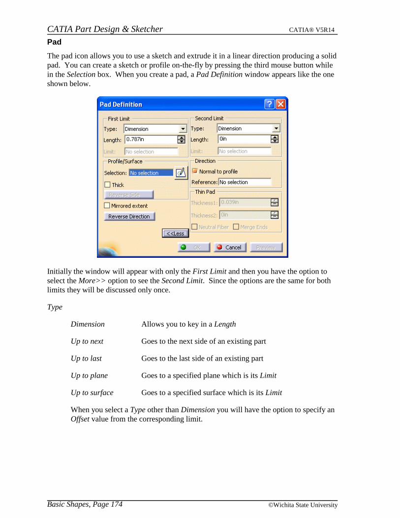
The pad icon allows you to use a sketch and extrude it in a linear direction producing a solidpad. You can create a sketch or profile on-the-fly by pressing the third mouse button whilein the Selection box. When you create a pad, a Pad Definition window appears like the oneshown below.
Initially the window will appear with only the First Limit and then you have the option toselect the More>> option to see the Second Limit. Since the options are the same for bothlimits they will be discussed only once.
Type
Dimension Allows you to key in a Length
Up to next Goes to the next side of an existing part
Up to last Goes to the last side of an existing part
Up to plane Goes to a specified plane which is its Limit
Up to surface Goes to a specified surface which is its Limit
When you select a Type other than Dimension you will have the option to specify anOffset value from the corresponding limit.
CATIA Part Design & Sketcher CATIA® V5R14
Basic Shapes, Page 175© Wichita State University
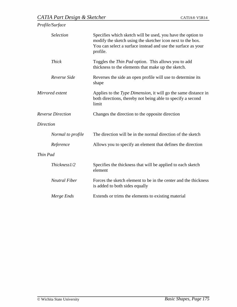
Profile/Surface
Selection Specifies which sketch will be used, you have the option tomodify the sketch using the sketcher icon next to the box.You can select a surface instead and use the surface as yourprofile.
Thick Toggles the Thin Pad option. This allows you to addthickness to the elements that make up the sketch.
Reverse Side Reverses the side an open profile will use to determine itsshape
Mirrored extent Applies to the Type Dimension, it will go the same distance inboth directions, thereby not being able to specify a secondlimit
Reverse Direction Changes the direction to the opposite direction
Direction
Normal to profile The direction will be in the normal direction of the sketch
Reference Allows you to specify an element that defines the direction
Thin Pad
Thickness1/2 Specifies the thickness that will be applied to each sketchelement
Neutral Fiber Forces the sketch element to be in the center and the thicknessis added to both sides equally
Merge Ends Extends or trims the elements to existing material
CATIA Part Design & Sketcher CATIA® V5R14
Basic Shapes, Page 176 ©Wichita State University
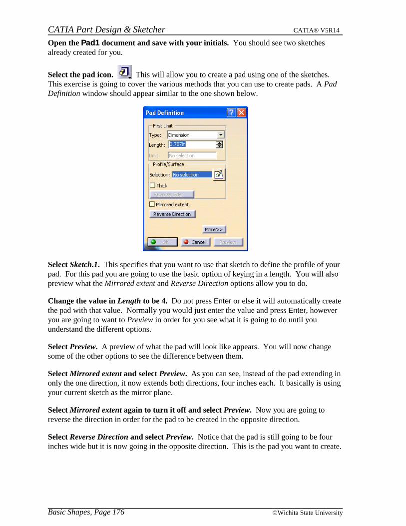
Open the Pad1 document and save with your initials. You should see two sketchesalready created for you.
Select the pad icon. This will allow you to create a pad using one of the sketches.This exercise is going to cover the various methods that you can use to create pads. A PadDefinition window should appear similar to the one shown below.
Select Sketch.1. This specifies that you want to use that sketch to define the profile of yourpad. For this pad you are going to use the basic option of keying in a length. You will alsopreview what the Mirrored extent and Reverse Direction options allow you to do.
Change the value in Length to be 4. Do not press Enter or else it will automatically createthe pad with that value. Normally you would just enter the value and press Enter, howeveryou are going to want to Preview in order for you see what it is going to do until youunderstand the different options.
Select Preview. A preview of what the pad will look like appears. You will now changesome of the other options to see the difference between them.
Select Mirrored extent and select Preview. As you can see, instead of the pad extending inonly the one direction, it now extends both directions, four inches each. It basically is usingyour current sketch as the mirror plane.
Select Mirrored extent again to turn it off and select Preview. Now you are going toreverse the direction in order for the pad to be created in the opposite direction.
Select Reverse Direction and select Preview. Notice that the pad is still going to be fourinches wide but it is now going in the opposite direction. This is the pad you want to create.
CATIA Part Design & Sketcher CATIA® V5R14
Basic Shapes, Page 177© Wichita State University
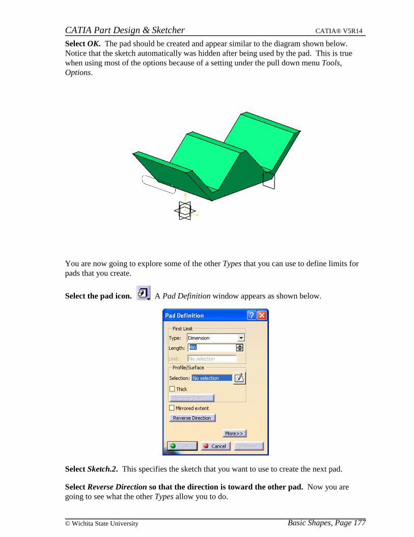
Select OK. The pad should be created and appear similar to the diagram shown below.Notice that the sketch automatically was hidden after being used by the pad. This is truewhen using most of the options because of a setting under the pull down menu Tools,Options.
You are now going to explore some of the other Types that you can use to define limits forpads that you create.
Select the pad icon. A Pad Definition window appears as shown below.
Select Sketch.2. This specifies the sketch that you want to use to create the next pad.
Select Reverse Direction so that the direction is toward the other pad. Now you aregoing to see what the other Types allow you to do.
CATIA Part Design & Sketcher CATIA® V5R14
Basic Shapes, Page 178 ©Wichita State University
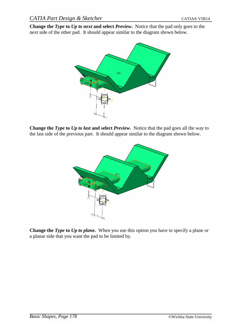
Change the Type to Up to next and select Preview. Notice that the pad only goes to thenext side of the other pad. It should appear similar to the diagram shown below.
Change the Type to Up to last and select Preview. Notice that the pad goes all the way tothe last side of the previous part. It should appear similar to the diagram shown below.
Change the Type to Up to plane. When you use this option you have to specify a plane ora planar side that you want the pad to be limited by.
CATIA Part Design & Sketcher CATIA® V5R14
Basic Shapes, Page 179© Wichita State University
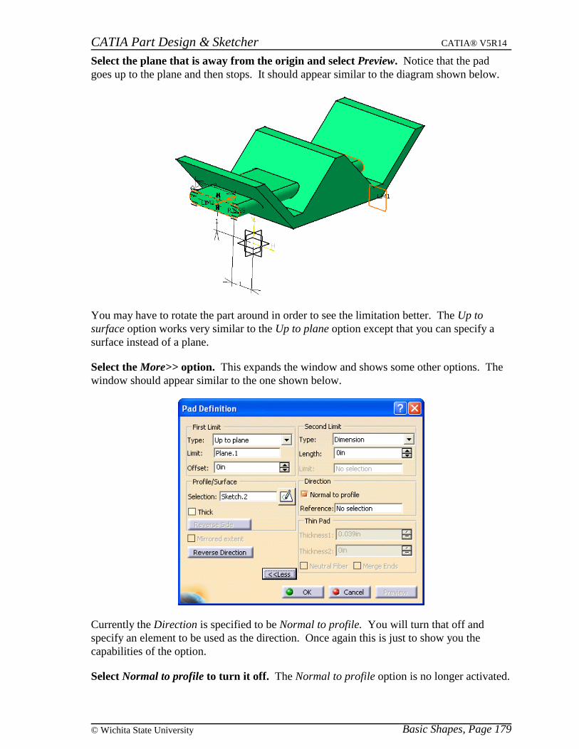
Select the plane that is away from the origin and select Preview. Notice that the padgoes up to the plane and then stops. It should appear similar to the diagram shown below.
You may have to rotate the part around in order to see the limitation better. The Up tosurface option works very similar to the Up to plane option except that you can specify asurface instead of a plane.
Select the More>> option. This expands the window and shows some other options. Thewindow should appear similar to the one shown below.
Currently the Direction is specified to be Normal to profile. You will turn that off andspecify an element to be used as the direction. Once again this is just to show you thecapabilities of the option.
Select Normal to profile to turn it off. The Normal to profile option is no longer activated.
CATIA Part Design & Sketcher CATIA® V5R14
Basic Shapes, Page 180 ©Wichita State University
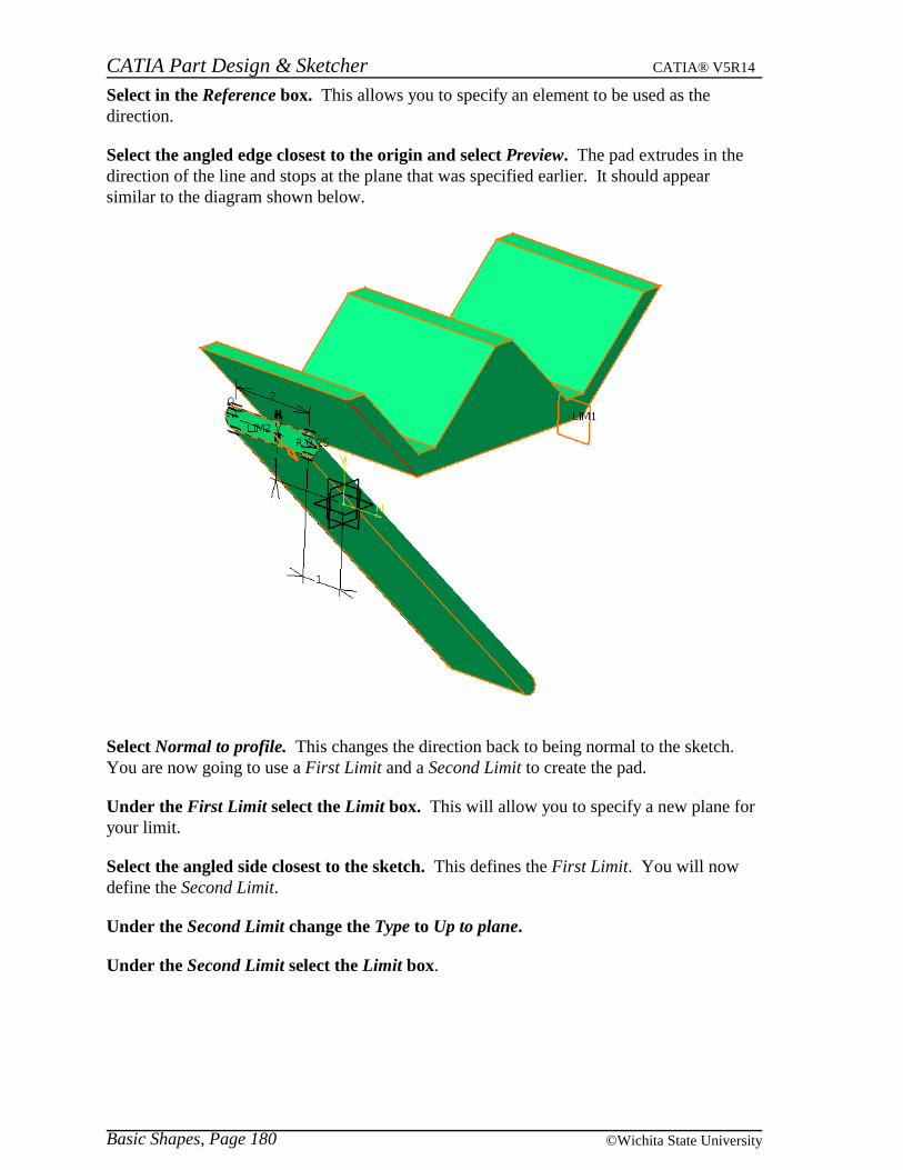
Select in the Reference box. This allows you to specify an element to be used as thedirection.
Select the angled edge closest to the origin and select Preview. The pad extrudes in thedirection of the line and stops at the plane that was specified earlier. It should appearsimilar to the diagram shown below.
Select Normal to profile. This changes the direction back to being normal to the sketch.You are now going to use a First Limit and a Second Limit to create the pad.
Under the First Limit select the Limit box. This will allow you to specify a new plane foryour limit.
Select the angled side closest to the sketch. This defines the First Limit. You will nowdefine the Second Limit.
Under the Second Limit change the Type to Up to plane.
Under the Second Limit select the Limit box.

CATIA Part Design & Sketcher CATIA® V5R14
Basic Shapes, Page 181© Wichita State University
Select the angled side farthest from the sketch and select Preview. This defines theSecond Limit and shows you a preview of your new pad. It should appear similar to thediagram shown below.
Select OK. The final part should look similar to the diagram shown below.
This exercise showed most of the options available when creating a pad. There are othershapes that have these same options and they work the same. Hopefully you have a goodunderstanding of what each option allows you to do.
Note: Open profiles (sketches) can be used to create pads or pockets as long as they willbe closed by the other faces of your existing part.
Save and close your document.
CATIA Part Design & Sketcher CATIA® V5R14
Basic Shapes, Page 182 ©Wichita State University
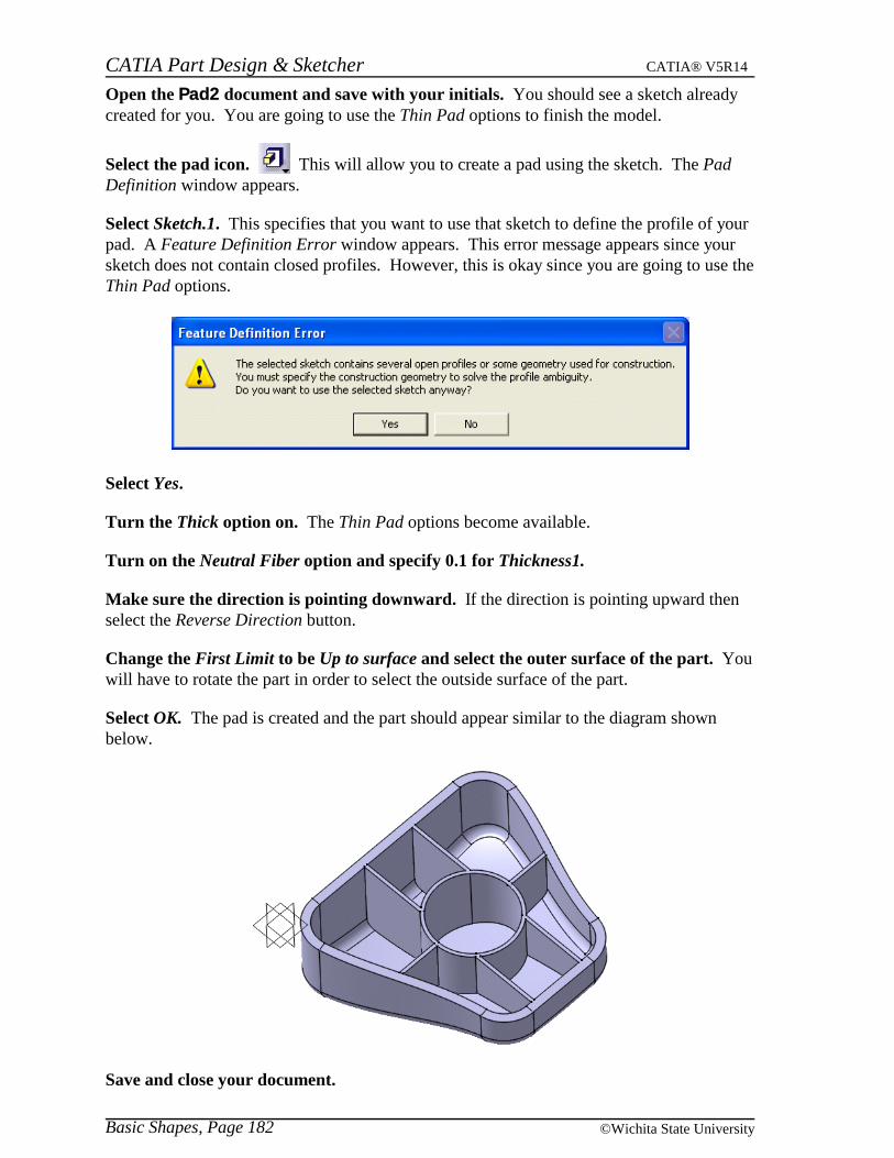
Open the Pad2 document and save with your initials. You should see a sketch alreadycreated for you. You are going to use the Thin Pad options to finish the model.
Select the pad icon. This will allow you to create a pad using the sketch. The PadDefinition window appears.
Select Sketch.1. This specifies that you want to use that sketch to define the profile of yourpad. A Feature Definition Error window appears. This error message appears since yoursketch does not contain closed profiles. However, this is okay since you are going to use theThin Pad options.
Select Yes.
Turn the Thick option on. The Thin Pad options become available.
Turn on the Neutral Fiber option and specify 0.1 for Thickness1.
Make sure the direction is pointing downward. If the direction is pointing upward thenselect the Reverse Direction button.
Change the First Limit to be Up to surface and select the outer surface of the part. Youwill have to rotate the part in order to select the outside surface of the part.
Select OK. The pad is created and the part should appear similar to the diagram shownbelow.
Save and close your document.
CATIA Part Design & Sketcher CATIA® V5R14
Basic Shapes, Page 183© Wichita State University
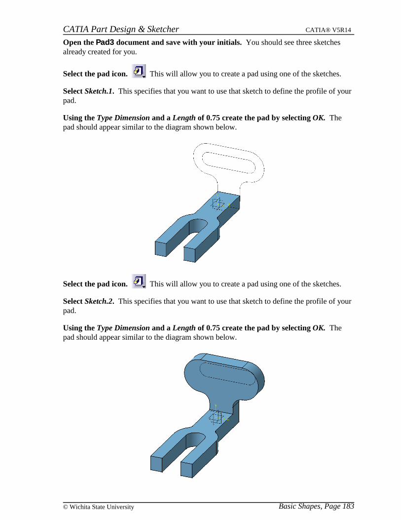
Open the Pad3 document and save with your initials. You should see three sketchesalready created for you.
Select the pad icon. This will allow you to create a pad using one of the sketches.
Select Sketch.1. This specifies that you want to use that sketch to define the profile of yourpad.
Using the Type Dimension and a Length of 0.75 create the pad by selecting OK. Thepad should appear similar to the diagram shown below.
Select the pad icon. This will allow you to create a pad using one of the sketches.
Select Sketch.2. This specifies that you want to use that sketch to define the profile of yourpad.
Using the Type Dimension and a Length of 0.75 create the pad by selecting OK. Thepad should appear similar to the diagram shown below.
CATIA Part Design & Sketcher CATIA® V5R14
Basic Shapes, Page 184 ©Wichita State University
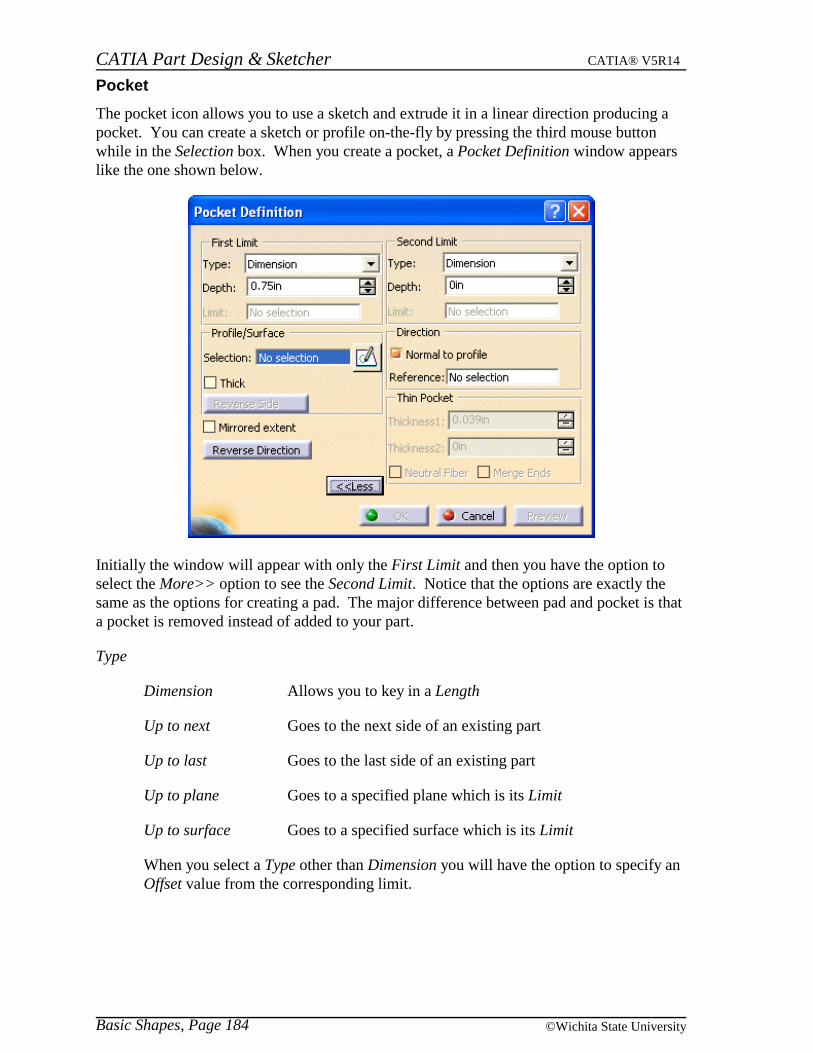
The pocket icon allows you to use a sketch and extrude it in a linear direction producing apocket. You can create a sketch or profile on-the-fly by pressing the third mouse buttonwhile in the Selection box. When you create a pocket, a Pocket Definition window appearslike the one shown below.
Initially the window will appear with only the First Limit and then you have the option toselect the More>> option to see the Second Limit. Notice that the options are exactly thesame as the options for creating a pad. The major difference between pad and pocket is thata pocket is removed instead of added to your part.
Type
Dimension Allows you to key in a Length
Up to next Goes to the next side of an existing part
Up to last Goes to the last side of an existing part
Up to plane Goes to a specified plane which is its Limit
Up to surface Goes to a specified surface which is its Limit
When you select a Type other than Dimension you will have the option to specify anOffset value from the corresponding limit.

CATIA Part Design & Sketcher CATIA® V5R14
Basic Shapes, Page 185© Wichita State University
Profile/Surface
Selection Specifies which sketch will be used, you have the option tomodify the sketch using the sketcher icon next to the box.You can select a surface instead and use the surface as yourprofile.
Thick Toggles the Thin Pad option. This allows you to addthickness to the elements that make up the sketch.
Reverse Side Reverses the side an open profile will use to determine itsshape
Mirrored extent Applies to the Type Dimension, it will go the same distance inboth directions, thereby not being able to specify a secondlimit
Reverse Direction Changes the direction to the opposite direction
Direction
Normal to profile The direction will be in the normal direction of the sketch
Reference Allows you to specify an element that defines the direction
Thin Pad
Thickness1/2 Specifies the thickness that will be applied to each sketchelement
Neutral Fiber Forces the sketch element to be in the center and the thicknessis added to both sides equally
Merge Ends Extends or trims the elements to existing material
CATIA Part Design & Sketcher CATIA® V5R14
Basic Shapes, Page 186 ©Wichita State University
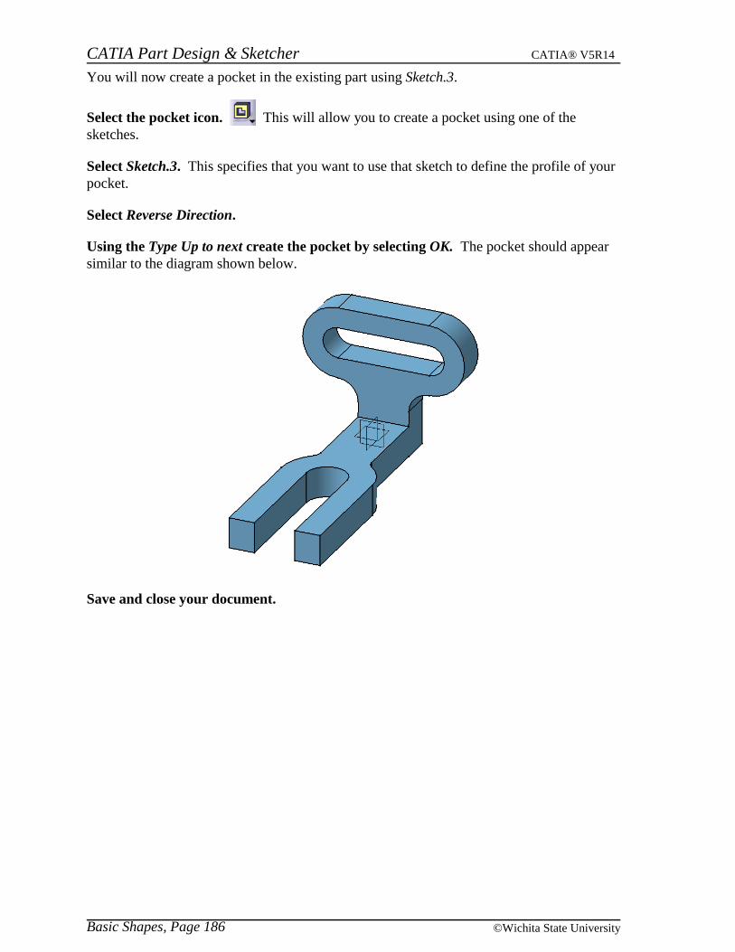
You will now create a pocket in the existing part using Sketch.3.
Select the pocket icon. This will allow you to create a pocket using one of thesketches.
Select Sketch.3. This specifies that you want to use that sketch to define the profile of yourpocket.
Select Reverse Direction.
Using the Type Up to next create the pocket by selecting OK. The pocket should appearsimilar to the diagram shown below.
Save and close your document.
CATIA Part Design & Sketcher CATIA® V5R14
Basic Shapes, Page 187© Wichita State University
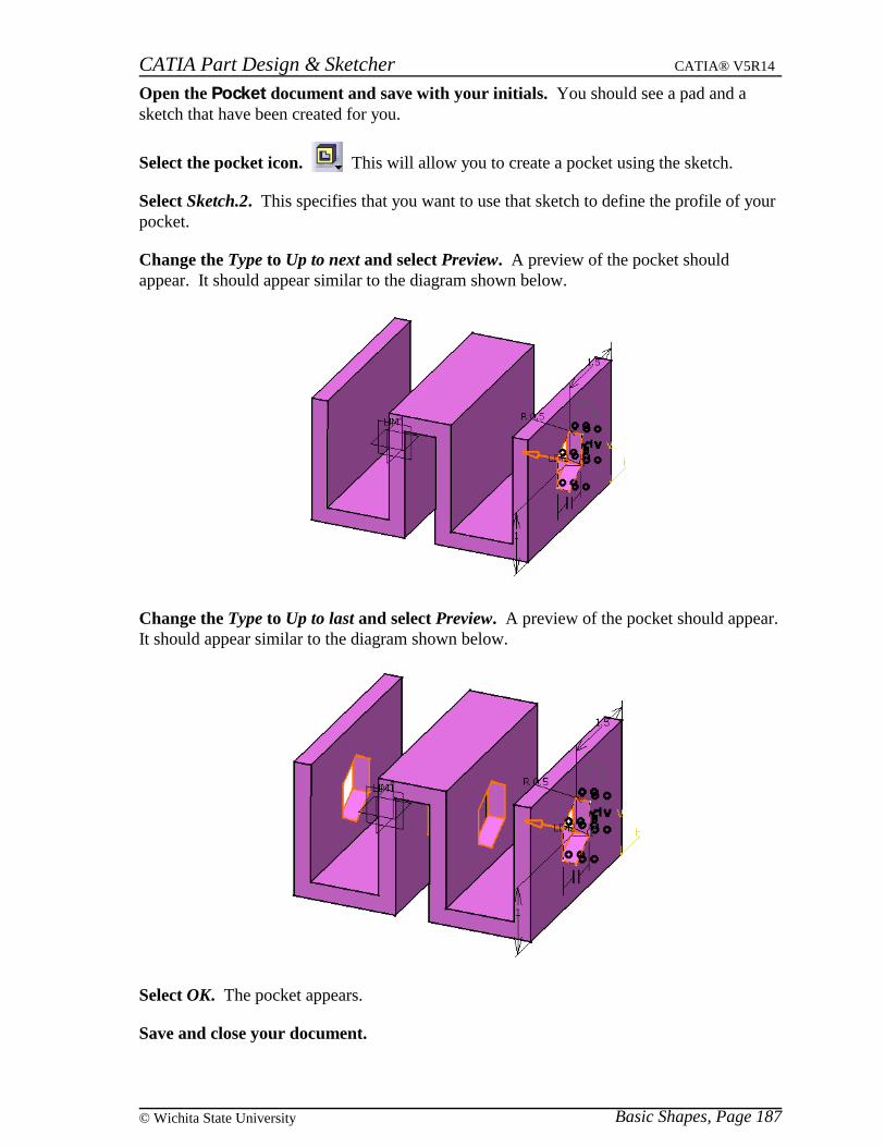
Open the Pocket document and save with your initials. You should see a pad and asketch that have been created for you.
Select the pocket icon. This will allow you to create a pocket using the sketch.
Select Sketch.2. This specifies that you want to use that sketch to define the profile of yourpocket.
Change the Type to Up to next and select Preview. A preview of the pocket shouldappear. It should appear similar to the diagram shown below.
Change the Type to Up to last and select Preview. A preview of the pocket should appear.It should appear similar to the diagram shown below.
Select OK. The pocket appears.
Save and close your document.
CATIA Part Design & Sketcher CATIA® V5R14
Basic Shapes, Page 188 ©Wichita State University
Multiple Profiles
You can create objects using a single profile of a sketch that contains multiple profiles.This allows you to create multiple profiles on the same sketch and then using pad or pocketyou can have each profile extrude a different distance as if they were separate sketches.When you do this each pad or pocket will reference the same sketch, just a different part ofthe sketch.
Open the Multiple profiles document and save with your initials. You should see asketch that has already been created for you.
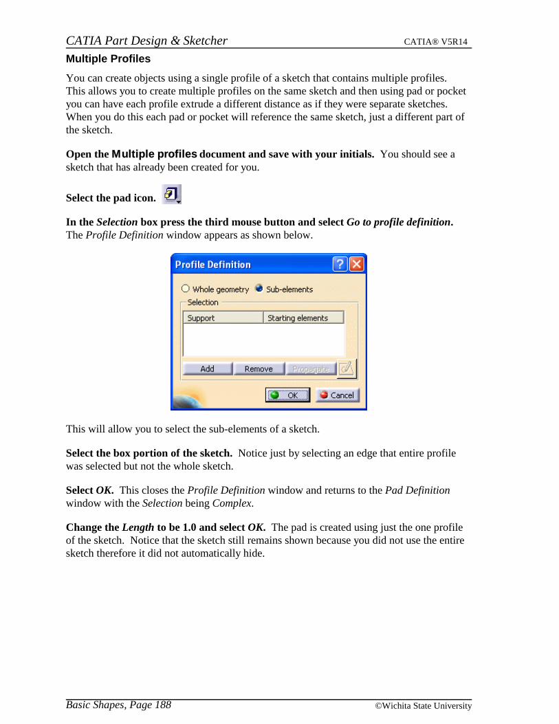
Select the pad icon.
In the Selection box press the third mouse button and select Go to profile definition.The Profile Definition window appears as shown below.
This will allow you to select the sub-elements of a sketch.
Select the box portion of the sketch. Notice just by selecting an edge that entire profilewas selected but not the whole sketch.
Select OK. This closes the Profile Definition window and returns to the Pad Definitionwindow with the Selection being Complex.
Change the Length to be 1.0 and select OK. The pad is created using just the one profileof the sketch. Notice that the sketch still remains shown because you did not use the entiresketch therefore it did not automatically hide.
CATIA Part Design & Sketcher CATIA® V5R14
Basic Shapes, Page 189© Wichita State University
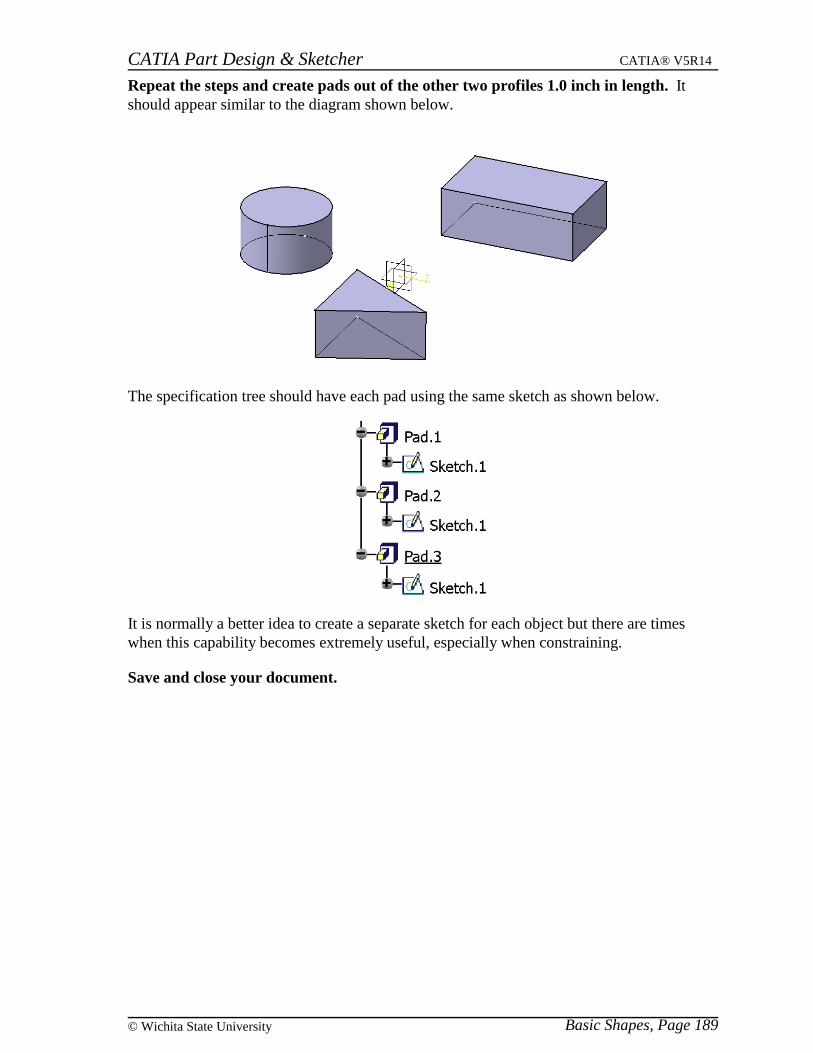
Repeat the steps and create pads out of the other two profiles 1.0 inch in length. Itshould appear similar to the diagram shown below.
The specification tree should have each pad using the same sketch as shown below.
It is normally a better idea to create a separate sketch for each object but there are timeswhen this capability becomes extremely useful, especially when constraining.
Save and close your document.
CATIA Part Design & Sketcher CATIA® V5R14
Basic Shapes, Page 190 ©Wichita State University
Multi-Pad and Multi-Pocket
There is another option to creating a pad or pocket with a sketch that contains multipleprofiles. Each profile can have its own distance but, instead of using a portion of a sketchfor each pocket or pad you can create one pad or pocket using all the different profiles of thesketch. These are referred to a multi-pads or multi-pockets. In this example you will becreating a multi-pocket but both options work very similarly.
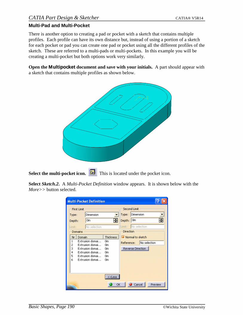
Open the Multipocket document and save with your initials. A part should appear witha sketch that contains multiple profiles as shown below.
Select the multi-pocket icon. This is located under the pocket icon.
Select Sketch.2. A Multi-Pocket Definition window appears. It is shown below with theMore>> button selected.
CATIA Part Design & Sketcher CATIA® V5R14
Basic Shapes, Page 191© Wichita State University
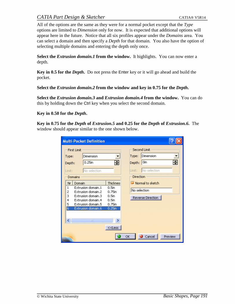
All of the options are the same as they were for a normal pocket except that the Typeoptions are limited to Dimension only for now. It is expected that additional options willappear here in the future. Notice that all six profiles appear under the Domains area. Youcan select a domain and then specify a Depth for that domain. You also have the option ofselecting multiple domains and entering the depth only once.
Select the Extrusion domain.1 from the window. It highlights. You can now enter adepth.
Key in 0.5 for the Depth. Do not press the Enter key or it will go ahead and build thepocket.
Select the Extrusion domain.2 from the window and key in 0.75 for the Depth.
Select the Extrusion domain.3 and Extrusion domain.4 from the window. You can dothis by holding down the Ctrl key when you select the second domain.
Key in 0.50 for the Depth.
Key in 0.75 for the Depth of Extrusion.5 and 0.25 for the Depth of Extrusion.6. Thewindow should appear similar to the one shown below.
CATIA Part Design & Sketcher CATIA® V5R14
Basic Shapes, Page 192 ©Wichita State University
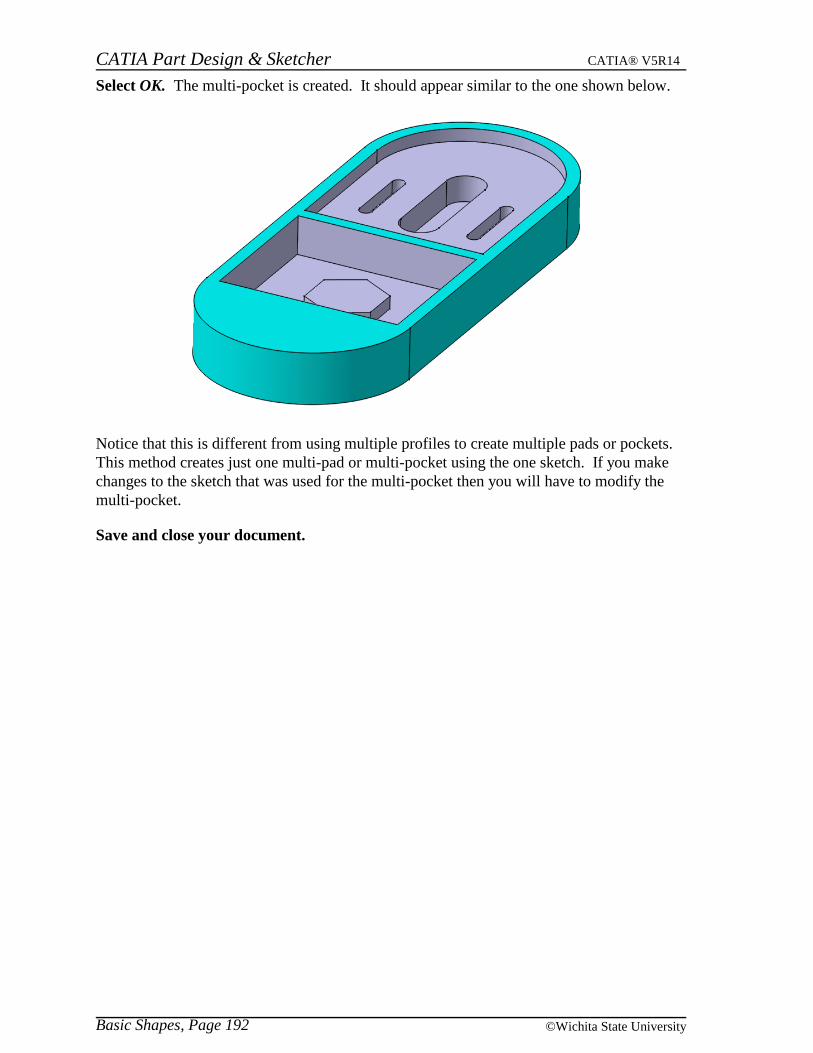
Select OK. The multi-pocket is created. It should appear similar to the one shown below.
Notice that this is different from using multiple profiles to create multiple pads or pockets.This method creates just one multi-pad or multi-pocket using the one sketch. If you makechanges to the sketch that was used for the multi-pocket then you will have to modify themulti-pocket.
Save and close your document.

.
Other available courses
CATIA V5 and ENOVIA• CATIA Basic Concepts• CATIA Part Design & Sketcher• CATIA Assembly Design• CATIA Drafting• CATIA Wireframe & Surfaces• CATIA Prismatic Machining • CATIA Surface Machining• CATIA Fitting Simulation & Kinematics• CATIA Functional Tolerancing & Annotation• CATIA Stress Analysis• ENOVIA DMU Viewer• ENOVIA LCA Basic Concepts• ENOVIA LCA Advanced Concepts• ENOVIA LCA Product Design
To enroll in any of the above courses, contact us at: (316) 978-3283toll-free at: 1-800-NIARWSU or email: [email protected]