Embed Size (px)
Citation preview
©2009 Bose CorporationReference Number 317302-SM Rev. 00
Service Manual
Panaray® MA12EX Modular Line ArrayLoudspeaker System
Electronic Copy Only
2
CAUTION: The Bose® Panaray MA12EX Modular Line Array Loudspeaker Systemcontains no user-serviceable parts. To prevent warranty infractions,
refer servicing to warranty service stations or factory service.
PROPRIETARY INFORMATION
THIS DOCUMENT CONTAINS PROPRIETARY INFORMATION OFBOSE CORPORATION WHICH IS BEING FURNISHED ONLY FORTHE PURPOSE OF SERVICING THE IDENTIFIED BOSE PRODUCTBY AN AUTHORIZED BOSE SERVICE CENTER OR OWNER OFTHE BOSE PRODUCT, AND SHALL NOT BE REPRODUCED ORUSED FOR ANY OTHER PURPOSE.
The Bose Panaray MA12EX Modular Line Array Loudspeaker System is covered by a 5-yeartransferable limited warranty.
Warranty
Contents
Warranty .............................................................................................................................................2Specifications ....................................................................................................................................3Product Description ..........................................................................................................................3Accessories Used with the MA12EX Loudspeaker System ..........................................................3Part List Notes ...................................................................................................................................3Packaging Part List, Panaray® MA12EX Loudspeaker System (see Figure 1) ............................4
Figure 1. Panaray MA12EX Loudspeaker Packaging View .............................................................4Packaging Part List, Panaray MA12EX Transformer Accessory (see Figure 2) ..........................5
Figure 2. Panaray MA12EX 70/100V Transformer Accessory Packing View ...................................5Main Part List, Panaray MA12EX Loudspeaker System (see Figure 3)........................................6
Figure 3. Panaray MA12EX Loudspeaker System Exploded View ..................................................7Main Part List, Panaray CVT-MA12EX Transformer Accessory (see Figure 4) ............................8
Figure 4. Panaray CVT-MA12EX 70/100V Transformer Accessory Exploded View.........................8Disassembly Procedures ........................................................................................................... 9-10MA12EX Loudspeaker ......................................................................................................................9CVT-MA12EX Transformer Accessory ...........................................................................................10Test Procedures .............................................................................................................................. 11
Figure 5. Panaray MA12EX Test Setup Diagram ........................................................................... 11Figure 6. Panaray MA12EX Loudspeaker Wiring Diagram ............................................................12
Service Manual Revision History...................................................................................................13
3
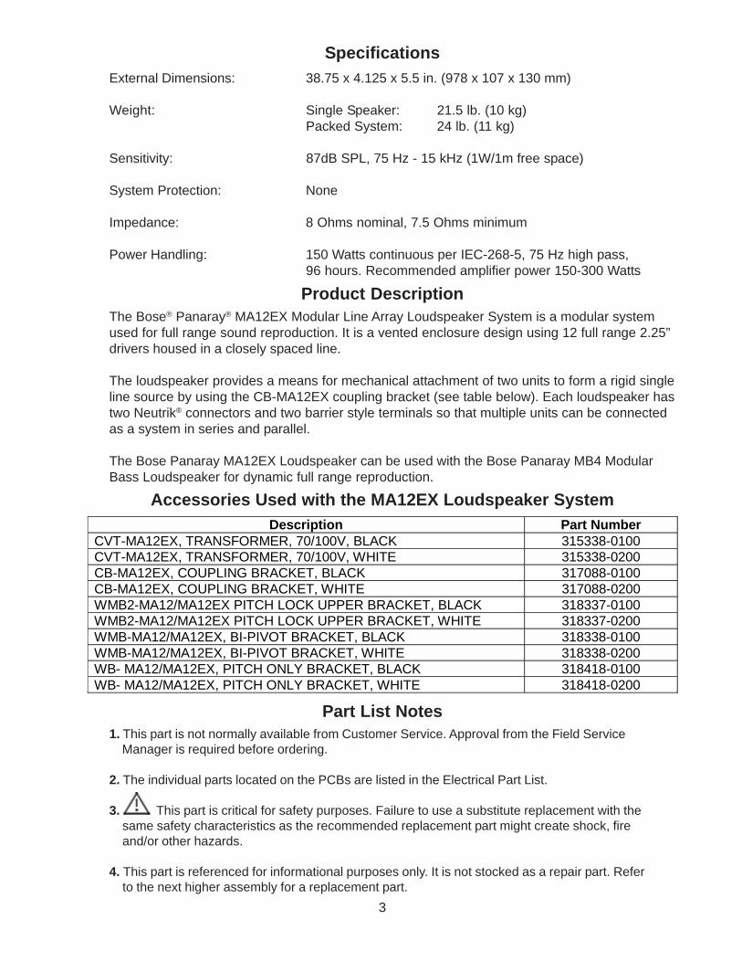
SpecificationsExternal Dimensions: 38.75 x 4.125 x 5.5 in. (978 x 107 x 130 mm)
Weight: Single Speaker: 21.5 lb. (10 kg)Packed System: 24 lb. (11 kg)
Sensitivity: 87dB SPL, 75 Hz - 15 kHz (1W/1m free space)
System Protection: None
Impedance: 8 Ohms nominal, 7.5 Ohms minimum
Power Handling: 150 Watts continuous per IEC-268-5, 75 Hz high pass,96 hours. Recommended amplifier power 150-300 Watts
The Bose® Panaray® MA12EX Modular Line Array Loudspeaker System is a modular systemused for full range sound reproduction. It is a vented enclosure design using 12 full range 2.25”drivers housed in a closely spaced line.
The loudspeaker provides a means for mechanical attachment of two units to form a rigid singleline source by using the CB-MA12EX coupling bracket (see table below). Each loudspeaker hastwo Neutrik® connectors and two barrier style terminals so that multiple units can be connectedas a system in series and parallel.
The Bose Panaray MA12EX Loudspeaker can be used with the Bose Panaray MB4 ModularBass Loudspeaker for dynamic full range reproduction.
Accessories Used with the MA12EX Loudspeaker System
Part List Notes1. This part is not normally available from Customer Service. Approval from the Field Service Manager is required before ordering.
2. The individual parts located on the PCBs are listed in the Electrical Part List.
3. This part is critical for safety purposes. Failure to use a substitute replacement with the same safety characteristics as the recommended replacement part might create shock, fire and/or other hazards.
4. This part is referenced for informational purposes only. It is not stocked as a repair part. Refer to the next higher assembly for a replacement part.
Description Part Number CVT-MA12EX, TRANSFORMER, 70/100V, BLACK 315338-0100 CVT-MA12EX, TRANSFORMER, 70/100V, WHITE 315338-0200 CB-MA12EX, COUPLING BRACKET, BLACK 317088-0100 CB-MA12EX, COUPLING BRACKET, WHITE 317088-0200 WMB2-MA12/MA12EX PITCH LOCK UPPER BRACKET, BLACK 318337-0100 WMB2-MA12/MA12EX PITCH LOCK UPPER BRACKET, WHITE 318337-0200 WMB-MA12/MA12EX, BI-PIVOT BRACKET, BLACK 318338-0100 WMB-MA12/MA12EX, BI-PIVOT BRACKET, WHITE 318338-0200 WB- MA12/MA12EX, PITCH ONLY BRACKET, BLACK 318418-0100 WB- MA12/MA12EX, PITCH ONLY BRACKET, WHITE 318418-0200
Product Description
4
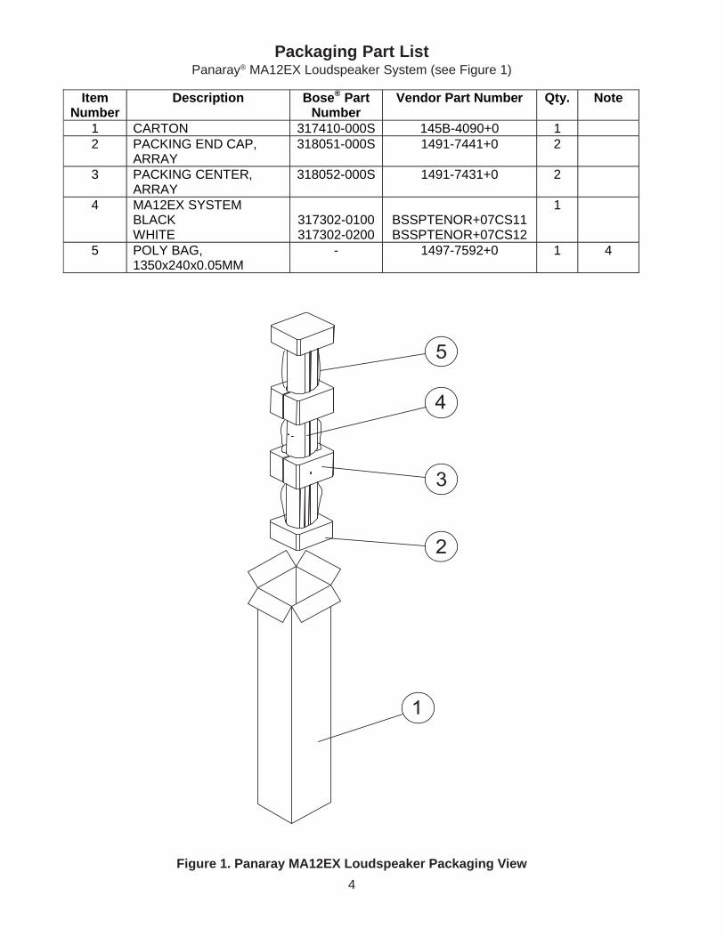
Figure 1. Panaray MA12EX Loudspeaker Packaging View
Packaging Part ListPanaray® MA12EX Loudspeaker System (see Figure 1)
1
2
3
4
5
Item Number
Description Bose® Part Number
Vendor Part Number Qty. Note
1 CARTON 317410-000S 145B-4090+0 1 2 PACKING END CAP,
ARRAY 318051-000S 1491-7441+0 2
3 PACKING CENTER, ARRAY
318052-000S 1491-7431+0 2
4 MA12EX SYSTEM BLACK WHITE
317302-0100 317302-0200
BSSPTENOR+07CS11 BSSPTENOR+07CS12
1
5 POLY BAG, 1350x240x0.05MM
- 1497-7592+0 1 4
5
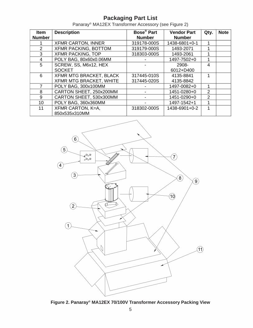
Packaging Part ListPanaray® MA12EX Transformer Accessory (see Figure 2)
Figure 2. Panaray® MA12EX 70/100V Transformer Accessory Packing View
6
5
4
3
2
1
7
89
10
11
Item Number
Description Bose® Part Number
Vendor Part Number
Qty. Note
1 XFMR CARTON, INNER 319178-000S 1438-6801+0-1 1 2 XFMR PACKING, BOTTOM 319179-000S 1493-2071 1 3 XFMR PACKING, TOP 318303-000S 1493-2061 1 4 POLY BAG, 80x60x0.06MM - 1497-7502+0 1 5 SCREW, SS, M6x12, HEX
SOCKET - 2908-
6012+D400 4
6 XFMR MTG BRACKET, BLACK 317445-010S 4135-8841 1 XFMR MTG BRACKET, WHITE 317445-020S 4135-8842
7 POLY BAG, 300x100MM - 1497-0082+0 1 8 CARTON SHEET, 250x200MM - 1451-0280+0 2 9 CARTON SHEET, 530x300MM - 1451-0290+0 2 10 POLY BAG, 360x360MM - 1497-1542+1 1 11 XFMR CARTON, K=A,
850x535x310MM 318302-000S 1438-6901+0-2 1
6
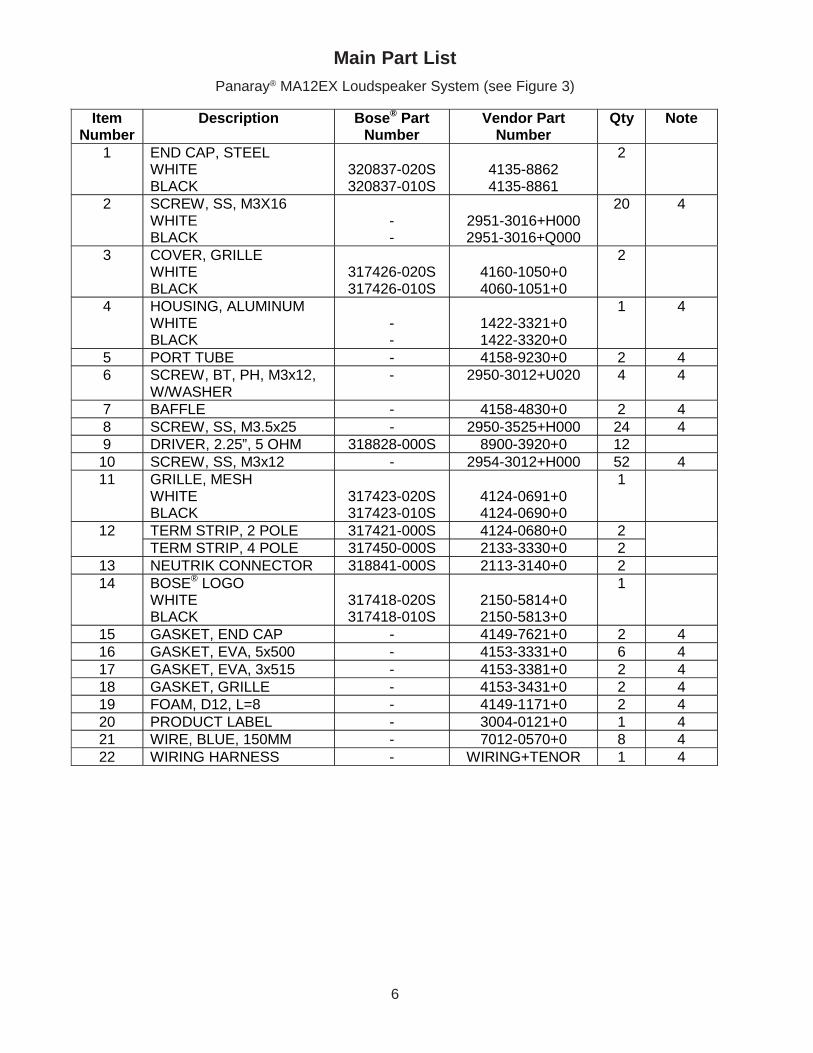
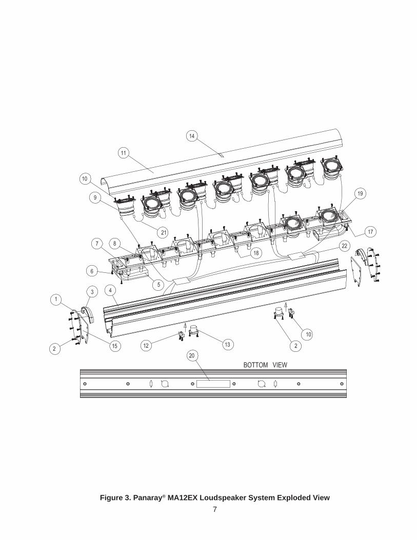
Main Part ListPanaray® MA12EX Loudspeaker System (see Figure 3)
Item Number
Description Bose® Part Number
Vendor Part Number
Qty Note
1 END CAP, STEEL WHITE BLACK
320837-020S 320837-010S
4135-8862 4135-8861
2
2 SCREW, SS, M3X16 WHITE BLACK
- -
2951-3016+H000 2951-3016+Q000
20 4
3 COVER, GRILLE WHITE BLACK
317426-020S 317426-010S
4160-1050+0 4060-1051+0
2
4 HOUSING, ALUMINUM WHITE BLACK
- -
1422-3321+0 1422-3320+0
1 4
5 PORT TUBE - 4158-9230+0 2 4 6 SCREW, BT, PH, M3x12,
W/WASHER - 2950-3012+U020 4 4
7 BAFFLE - 4158-4830+0 2 4 8 SCREW, SS, M3.5x25 - 2950-3525+H000 24 4 9 DRIVER, 2.25”, 5 OHM 318828-000S 8900-3920+0 12 10 SCREW, SS, M3x12 - 2954-3012+H000 52 4 11 GRILLE, MESH
WHITE BLACK
317423-020S 317423-010S
4124-0691+0 4124-0690+0
1
12 TERM STRIP, 2 POLE 317421-000S 4124-0680+0 2 TERM STRIP, 4 POLE 317450-000S 2133-3330+0 2
13 NEUTRIK CONNECTOR 318841-000S 2113-3140+0 2 14 BOSE® LOGO
WHITE BLACK
317418-020S 317418-010S
2150-5814+0 2150-5813+0
1
15 GASKET, END CAP - 4149-7621+0 2 4 16 GASKET, EVA, 5x500 - 4153-3331+0 6 4 17 GASKET, EVA, 3x515 - 4153-3381+0 2 4 18 GASKET, GRILLE - 4153-3431+0 2 4 19 FOAM, D12, L=8 - 4149-1171+0 2 4 20 PRODUCT LABEL - 3004-0121+0 1 4 21 WIRE, BLUE, 150MM - 7012-0570+0 8 4 22 WIRING HARNESS - WIRING+TENOR 1 4
7
Figure 3. Panaray® MA12EX Loudspeaker System Exploded View
8
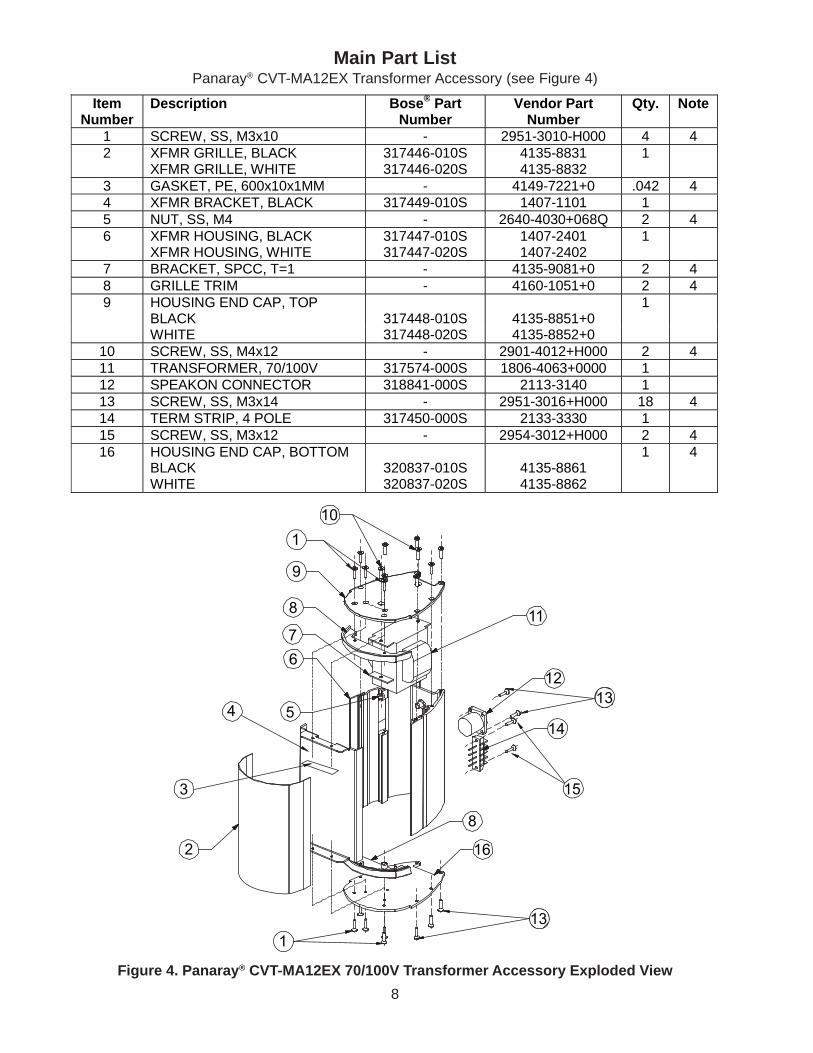
Main Part ListPanaray® CVT-MA12EX Transformer Accessory (see Figure 4)
Figure 4. Panaray® CVT-MA12EX 70/100V Transformer Accessory Exploded View
1
2
3
4 5
67
8
9
110
11
1213
14
15
8
16
13
Item Number
Description Bose® Part Number
Vendor Part Number
Qty. Note
1 SCREW, SS, M3x10 - 2951-3010-H000 4 4 2 XFMR GRILLE, BLACK 317446-010S 4135-8831 1 XFMR GRILLE, WHITE 317446-020S 4135-8832
3 GASKET, PE, 600x10x1MM - 4149-7221+0 .042 4 4 XFMR BRACKET, BLACK 317449-010S 1407-1101 1 5 NUT, SS, M4 - 2640-4030+068Q 2 4 6 XFMR HOUSING, BLACK 317447-010S 1407-2401 1 XFMR HOUSING, WHITE 317447-020S 1407-2402
7 BRACKET, SPCC, T=1 - 4135-9081+0 2 4 8 GRILLE TRIM - 4160-1051+0 2 4 9 HOUSING END CAP, TOP
BLACK
317448-010S
4135-8851+0 1
WHITE 317448-020S 4135-8852+0 10 SCREW, SS, M4x12 - 2901-4012+H000 2 4 11 TRANSFORMER, 70/100V 317574-000S 1806-4063+0000 1 12 SPEAKON CONNECTOR 318841-000S 2113-3140 1 13 SCREW, SS, M3x14 - 2951-3016+H000 18 4 14 TERM STRIP, 4 POLE 317450-000S 2133-3330 1 15 SCREW, SS, M3x12 - 2954-3012+H000 2 4 16 HOUSING END CAP, BOTTOM
BLACK
320837-010S
4135-8861 1 4
WHITE 320837-020S 4135-8862
9
Disassembly Procedures
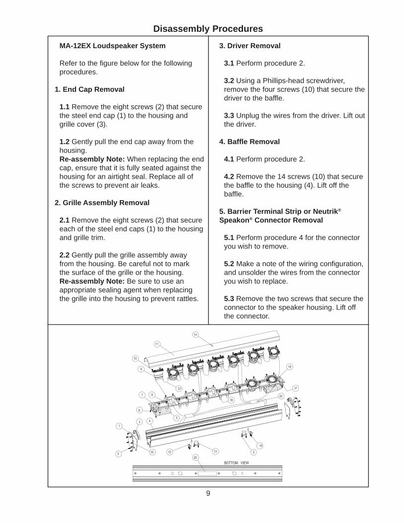
MA-12EX Loudspeaker System
Refer to the figure below for the followingprocedures.
1. End Cap Removal
1.1 Remove the eight screws (2) that securethe steel end cap (1) to the housing andgrille cover (3).
1.2 Gently pull the end cap away from thehousing.Re-assembly Note: When replacing the endcap, ensure that it is fully seated against thehousing for an airtight seal. Replace all ofthe screws to prevent air leaks.
2. Grille Assembly Removal
2.1 Remove the eight screws (2) that secureeach of the steel end caps (1) to the housingand grille trim.
2.2 Gently pull the grille assembly awayfrom the housing. Be careful not to markthe surface of the grille or the housing.Re-assembly Note: Be sure to use anappropriate sealing agent when replacingthe grille into the housing to prevent rattles.
3. Driver Removal
3.1 Perform procedure 2.
3.2 Using a Phillips-head screwdriver,remove the four screws (10) that secure thedriver to the baffle.
3.3 Unplug the wires from the driver. Lift outthe driver.
4. Baffle Removal
4.1 Perform procedure 2.
4.2 Remove the 14 screws (10) that securethe baffle to the housing (4). Lift off thebaffle.
5. Barrier Terminal Strip or Neutrik®
Speakon® Connector Removal
5.1 Perform procedure 4 for the connectoryou wish to remove.
5.2 Make a note of the wiring configuration,and unsolder the wires from the connectoryou wish to replace.
5.3 Remove the two screws that secure theconnector to the speaker housing. Lift offthe connector.
10
1
2
3
4 5
67
8
9
110
11
1213
14
15
8
16
13
Disassembly Procedures
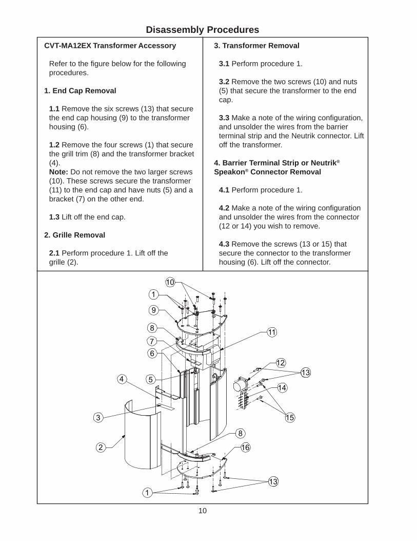
CVT-MA12EX Transformer Accessory
Refer to the figure below for the followingprocedures.
1. End Cap Removal
1.1 Remove the six screws (13) that securethe end cap housing (9) to the transformerhousing (6).
1.2 Remove the four screws (1) that securethe grill trim (8) and the transformer bracket(4).Note: Do not remove the two larger screws(10). These screws secure the transformer(11) to the end cap and have nuts (5) and abracket (7) on the other end.
1.3 Lift off the end cap.
2. Grille Removal
2.1 Perform procedure 1. Lift off thegrille (2).
3. Transformer Removal
3.1 Perform procedure 1.
3.2 Remove the two screws (10) and nuts(5) that secure the transformer to the endcap.
3.3 Make a note of the wiring configuration,and unsolder the wires from the barrierterminal strip and the Neutrik connector. Liftoff the transformer.
4. Barrier Terminal Strip or Neutrik®
Speakon® Connector Removal
4.1 Perform procedure 1.
4.2 Make a note of the wiring configurationand unsolder the wires from the connector(12 or 14) you wish to remove.
4.3 Remove the screws (13 or 15) thatsecure the connector to the transformerhousing (6). Lift off the connector.
11
Test Procedures
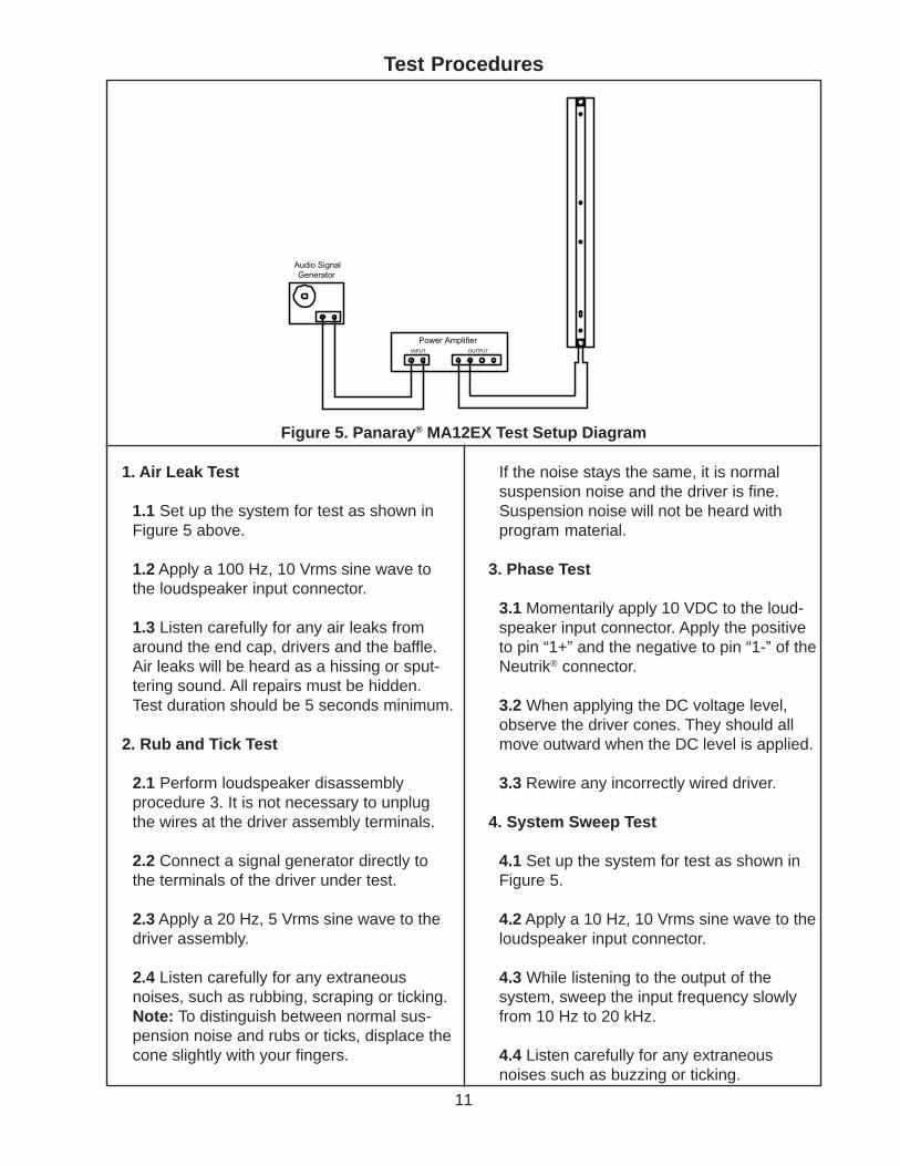
1. Air Leak Test
1.1 Set up the system for test as shown inFigure 5 above.
1.2 Apply a 100 Hz, 10 Vrms sine wave tothe loudspeaker input connector.
1.3 Listen carefully for any air leaks fromaround the end cap, drivers and the baffle.Air leaks will be heard as a hissing or sput-tering sound. All repairs must be hidden.Test duration should be 5 seconds minimum.
2. Rub and Tick Test
2.1 Perform loudspeaker disassemblyprocedure 3. It is not necessary to unplugthe wires at the driver assembly terminals.
2.2 Connect a signal generator directly tothe terminals of the driver under test.
2.3 Apply a 20 Hz, 5 Vrms sine wave to thedriver assembly.
2.4 Listen carefully for any extraneousnoises, such as rubbing, scraping or ticking.Note: To distinguish between normal sus-pension noise and rubs or ticks, displace thecone slightly with your fingers.
If the noise stays the same, it is normalsuspension noise and the driver is fine.Suspension noise will not be heard withprogram material.
3. Phase Test
3.1 Momentarily apply 10 VDC to the loud-speaker input connector. Apply the positiveto pin “1+” and the negative to pin “1-” of theNeutrik® connector.
3.2 When applying the DC voltage level,observe the driver cones. They should allmove outward when the DC level is applied.
3.3 Rewire any incorrectly wired driver.
4. System Sweep Test
4.1 Set up the system for test as shown inFigure 5.
4.2 Apply a 10 Hz, 10 Vrms sine wave to theloudspeaker input connector.
4.3 While listening to the output of thesystem, sweep the input frequency slowlyfrom 10 Hz to 20 kHz.
4.4 Listen carefully for any extraneousnoises such as buzzing or ticking.
Power AmplifierINPUT OUTPUT
Audio SignalGenerator
Figure 5. Panaray® MA12EX Test Setup Diagram
12
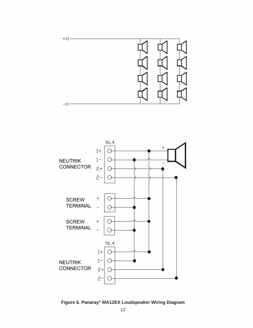
Figure 6. Panaray® MA12EX Loudspeaker Wiring Diagram
NEUTRIKCONNECTOR
SCREWTERMINAL
SCREWTERMINAL
NEUTRIKCONNECTOR
13
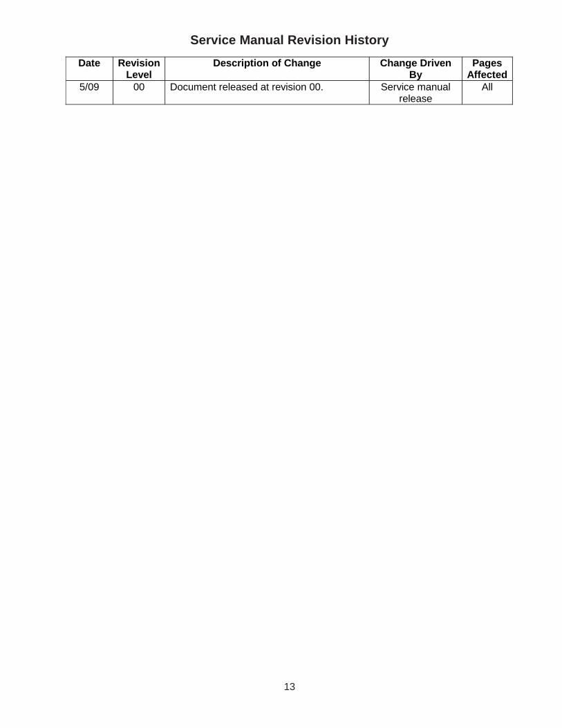
Service Manual Revision History
Date Revision Level
Description of Change Change Driven By
Pages Affected
5/09 00 Document released at revision 00. Service manual release
All
SPECIFICATIONS AND FEATURES SUBJECT TO CHANGE WITHOUT NOTICE
Bose CorporationThe MountainFramingham Massachusetts USA 01701
P/N: 317302-SM Rev. 00 5/2009 (P)http://serviceops.bose.com