Embed Size (px)
Citation preview

BIT102 Lab Name
Page 1 of 12
Packet Tracer Mini-Lab 08: Supplement Configuring 2 LANs/2 Routers using Config, CLI, & RIPv2
CAVEAT: THE LABS IN CC2-180 MAY NOT WORK ENTIRELY AS PLANNED. WE WILL BE UTILIZING BOTH A SERVER 2012 R2 HOST PC AND VIRTUAL MACHINES (VMs) ON THE HOST PC, IN WHICH CASE THERE MAY BE UNFORESEEN ISSUES. AS SUCH WE WILL LIKELY GET SOME UNEXPECTED ‘REAL WORLD’ TROUBLESHOOTING PRACTICE AND MAY EVEN HAVE TO “WING IT”
Mini-Lab 08 Objective
The lab provides further practice in a simulated environment using Cisco’s Packet Tracer application.
INSTRUCTIONS: You can use the Packet Tracer project (e.g., minilab05.pkt) created in Mini-Lab 5, which we are going to modify before starting this lab (we are going to remove the static routes in both routers, so the devices will no longer be able to ping across all the networks, then instead of using static routes we’ll use the RIP routing protocol).
Make a copy of that project and rename it to minilab08.pkt (or whatever naming convention you used previously).
If you do not have a copy of the previous project, then you will have to work through Mini-Lab 5 and save the project first before starting this lab (making sure to make a second copy of the completed lab then renaming that copy appropriately).

BIT102 Lab Name
Page 2 of 12
1. Open the copy of the project (e.g., copied/renamed minilab08.pkt) you created from the previous Mini-Lab 5 project (e.g., minilab05.pkt)
2. Click on PC1 and select the Desktop tab.
3. Select IP Configuration, and enter the following address information:
4. Click on PC2 and select the Desktop tab.
5. Select IP Configuration, and enter the following address information:

BIT102 Lab Name
Page 3 of 12
6. Click on PC3 and select the Desktop tab.
7. Select IP Configuration, and enter the following address information:
8. Click on PC4 and select the Desktop tab.
9. Select IP Configuration, and enter the following address information:

BIT102 Lab Name
Page 4 of 12
10. Click on Router 1 and select the Config tab.
11. Under ROUTING, select the Static bar.
12. In the Static Routes box, select 192.168.2.0/24 via Serial0/1/0, the click the Remove button.
13. The static route will be removed.

BIT102 Lab Name
Page 5 of 12
14. Select FastEthernet0/0 and enter the following address information
15. Select Serial0/1/0 and enter the following address information
16. Close the window, and click on Router 2 and select the Config tab.

BIT102 Lab Name
Page 6 of 12
17. Under ROUTING, select the Static bar.
18. In the Static Routes box, select 192.168.1.0/24 via Serial0/1/0, the click the Remove button.
19. The static route will be removed.
20. Select FastEthernet0/0 and enter the following address information
BIT102 Lab Name
Page 7 of 12
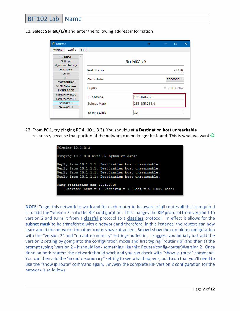
21. Select Serial0/1/0 and enter the following address information
22. From PC 1, try pinging PC 4 (10.1.3.3). You should get a Destination host unreachable response, because that portion of the network can no longer be found. This is what we want
NOTE: To get this network to work and for each router to be aware of all routes all that is required is to add the “version 2” into the RIP configuration. This changes the RIP protocol from version 1 to version 2 and turns it from a classful protocol to a classless protocol. In effect it allows for the subnet mask to be transferred with a network and therefore, in this instance, the routers can now learn about the networks the other routers have attached. Below I show the complete configuration with the “version 2” and “no auto-summary” settings added in. I suggest you initially just add the version 2 setting by going into the configuration mode and first typing “router rip” and then at the prompt typing “version 2 – it should look something like this: Router(config-router)#version 2. Once done on both routers the network should work and you can check with “show ip route” command. You can then add the “no auto-summary” setting to see what happens, but to do that you’ll need to use the “show ip route” command again. Anyway the complete RIP version 2 configuration for the network is as follows.

BIT102 Lab Name
Page 8 of 12
23. Close the windows, and click on Router 1 again and select the CLI tab; click in the CLI window and hit the Enter key to bring up the Router> prompt.
24. At the Router> prompt, type enable.
25. At the Router# prompt, type config t
26. At the Router(config)# prompt, type router rip
27. At the Router(config-router)# prompt, type version 2
28. At the Router(config-router)# prompt, type network 10.0.0.0, then Enter key, then network 192.168.2.0, then the Enter key again.
29. At the prompt, type exit to return to the previous prompt, then type exit again, then the Enter key.

BIT102 Lab Name
Page 9 of 12
30. If you want, you can see the running router configuration by typing show run and navigating down through the CLI window using Enter key
31. Close the window, and click on Router 2, then the CLI tab.
32. Click in the window and hit the Enter key to bring up the Router> prompt.
33. At the Router> prompt, type enable to bring up the Router# prompt, then type conf t to bring up the Router(config)# prompt.

BIT102 Lab Name
Page 10 of 12
34. At the Router(config)# prompt, type router rip
35. At the Router(config-router)# prompt, type version 2
36. At the Router(config-router)# prompt, type network 10.0.0.0, then Enter key, then network 192.168.2.0, then the Enter key again.
37. At the prompt, type exit to return to the previous prompt, then type exit again, then the Enter key.
BIT102 Lab Name
Page 11 of 12
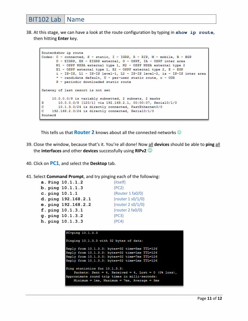
38. At this stage, we can have a look at the route configuration by typing in show ip route, then hitting Enter key.
This tells us that Router 2 knows about all the connected networks
39. Close the window, because that’s it. You’re all done! Now all devices should be able to ping all the interfaces and other devices successfully using RIPv2
40. Click on PC1, and select the Desktop tab.
41. Select Command Prompt, and try pinging each of the following: a. Ping 10.1.1.2 (itself) b. ping 10.1.1.3 (PC2) c. ping 10.1.1 (Router 1 fa0/0) d. ping 192.168.2.1 (router 1 s0/1/0) e. ping 192.168.2.2 (router 2 s0/1/0) f. ping 10.1.3.1 (router 2 fa0/0) g. ping 10.1.3.2 (PC3) h. ping 10.1.3.3 (PC4)
BIT102 Lab Name
Page 12 of 12
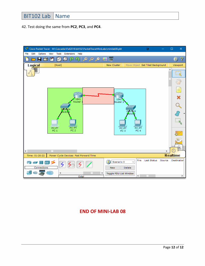
42. Test doing the same from PC2, PC3, and PC4.
END OF MINI-LAB 08