Embed Size (px)
Citation preview

PackagedElectromagneticClutches/Brakes
WARNERELECTRICCLUTCH/BRAKEPackagedElectromagneticClutches/Brakes
w w w . w a r n e r e l e c t r i c . c o m
Printed in USA
Warner Electric, Inc.449 Gardner Street • South Beloit, IL 61080815-389-3771 • Fax: 815-389-2582www.warnerelectric.com
P-1234 8/01****
Warner ElectricElectromagnetic Clutches and Brakes - USA
South Beloit, IL 61080815-389-3771
For application assistance:1-800-825-9050
Electromagnetic Clutches and Brakes - Europe
St Barthelemy d’Anjou, France+33 (0)2 41 21 24 24
For sales office:+33 (0)2 41 21 24 76
Precision Electric Coils andElectromagnetic Clutches and Brakes - USA
Columbia City, IN 46725260-244-6183
Inertia Dynamics Spring Set Brakes; Power On andWrap Spring Clutch/Brakes
Torrington, CT 06790860-482-4444
Matrix InternationalElectromagnetic Clutches and Brakes, Pressure Operated Clutches and Brakes
Brechin, Scotland+44 (0) 1356 602000
Warner LinearLinear Actuators and Guideways - USA
Belvidere, IL 61008815-547-1106
For application assistance:1-800-825-9050
Boston GearEnclosed and Open Gearing, Electrical and Mechanical P.T. Components, Precision Gearheads, Precision Couplings
Quincy, MA 02171617-328-3300
For customer service:1-888-999-9860
For application assistance:1-800-816-5608
Huco DynatorkPrecision Couplings and Air Motors
Hertford, England+44 (0) 1992 501900
Formsprag Clutch
Overrunning Clutches and Holdbacks
Warren, MI 48089586-758-5000
For application assistance:1-800-927-3262
Marland ClutchRoller Ramp and Sprag Type Overrunning Clutches and Backstops
Burr Ridge, IL 60527630-455-1752
Stieber Clutch Overrunning Clutches and Holdbacks
Heidelberg, Germany+49 (0)6221 30 47 0
Wichita Clutch and Industrial ClutchPneumatic and Oil ImmersedClutches and Brakes - USA
Wichita Falls, TX 76302940-723-3400
Pneumatic Clutches and Brakes - Europe
Bedford, England+44 (0)1234 350311
Twiflex LimitedCaliper Brakes and Thrusters
Twickenham, England+44 (0) 20 8894 1161
Ameridrives CouplingsGear Couplings, Mill Spindles,Universal Joints
Erie, PA 16512814-480-5000
Bibby TransmissionsDisc, Gear, Grid Couplings, Overload Clutches
Dewsbury, England+44 (0) 1924 460801
Nuttall Gear andDelroyd Worm GearWorm Gear and Helical Speed Reducers
Niagara Falls, NY 14302716-298-4100
Saftek FrictionNon-asbestos Brake and ClutchMaterials
Telford, England+44 (0) 1952 581122
Altra Industrial Motion -Asia Pacific and Africa
China 852 2615 9313
Taiwan 886 2 2577 8156
Singapore 65 487 4464
Thailand 66 2 322 0481
Australia 612 9894 0133
S. Africa 27 11 918 4270

Warner ElectricIndustrial Clutches and Brakes
Packaged NEMA C-faced
Electro Module (EM)
UniModule (UM)
Unimodule Ceramic (UM-C)
Enclosed UniModule (EUM)
Enclosed UniModule Washdown
Electrically Released Modules
Packaged Shaft & Foot Mounted
Electrically Released Brakes
Basic Clutches & Brakes
Wrap Spring Clutches & Brakes
Tension Clutches & Brakes
Turf & Garden Clutches & Brakes
Vehicular Clutches & Brakes
Controls for Clutches & Brakes
Tension Systems
Sensors & Switches
Accessories
Application Clutch / Brake Data Form
Product Warranty
Terms & Conditions
Web site Disclaimer
Check Outwarnerelectric.comwarnerelectric.com
Go to this interactive online resource when you want to explorethe unlimited potential of what you can do with Clutches,Brakes, Tensioning Control Systems, Sensors, Switches and other motioncontrol components. The site is dedicated to engineering needs,with many enhanced features and loads of rich, new content.
Within the Warner Electric Interactive eCATALOG, you can startyour search for basic equipment such as clutches or brakes,then quickly refine your search from hundreds of possibilitiesto a search that meets your specific power transmissionrequirements for NEMA, input/output configurations andother factors. You can also download specifications and PDFpages or submit a RFQ for any of your selections.
Find it fast at www.warnerelectric.com
warnerelectric.com now features our newinteractive eCATALOG making it faster and easier to find and spec the motioncontrol products you need.
OtherWarner Electric Clutch/Brake ProductsWarner Electric Clutch/Brake Products
Basic Design Clutches/Brakes• Electromagnetic clutches and brakes• Custom design with off-the-shelf components• Maximum mounting versatility• Wide range of sizes, torque ratings and configurations• Ideal for space restrictive applications
Catalog P-1264
Tension Control SystemsUp to 21,500 lb. ft. stopping torque• Complete system for unwind applications• Patented, new technology electric brakes• Sophisticated control systems• Load cell controls• Accurate, smooth, long lifeMagnetic Particle Clutches & BrakesTorque range 2 in. lb. to 240 in. lb.• For controlled starts and stops, tension
control, torque limiting and cyclingapplications
• High thermal ratings• Smooth, quiet frictionless operation
Catalog P-771
Overrunning ClutchesTorque loads to 700,000 lb. ft. (949200 Nm)• Overrunning, indexing and backstop-
ping applications• Instantaneous action, no backlash• More torque, less space• Full sprag complement with infinitely
changing wear parts
Catalog P-956
Warner Electric engineers, manufactures and markets, electromechanical components andsystems for controlling motion. Designed to help increase productivity, our products areincorporated into new equipment designs and are used to upgrade performance onmachines already in service. With an international organization of stocking distributors andsales centers, Warner Electric offers the most extensive network of its kind for locally avail-able products and professional, on-the-spot customer service.
Wrap Spring Clutches andClutch/Brakes• Accurate positioning with high torque-
to-size ratio• Long life, Maintenance free• Fast, repeatable performance• Pre-assembled, easy to install• Torque range from 25 lb.in. to
2,500 lb.in.• Over 25 sizes available
Catalog P-1310
Precision Tork• Fast, precise torque• Smooth, consistent torque to speed• No external control or power source
required• Long life, accurate• Versatile mounting: Easy to retrofit• Off-the-shelf availability
Catalog P-1316
ERD• Designed to keep load in position in
the event of power failure• Sizes from 3.3 in. to 9.9 in., 4 to
221 ft.lbs. of torque• Stops loads from speeds up to
3600 RPM• Quiet operation• Bi-directional stopping capability• Metric and inch standard bore sizes
Catalog P-1083
Sensors, Switches & SafetyTechnology ProductsFull line of Sensing, Switching andSafety Technology Products• Non Contact–Photoelectric,
Ultrasonic, Inductive, Capacitiveand Magnetic Sensors
• Contact–Limit Switches, Footswitches,Cable Pull Switches, and ConveyorBelt Alignment Switches
• Safety Switches–Safety InterlockSwitches (key and hinge styles),Solenoid Lock, Spring Lock, CablePull, Footswitch and Coded MagneticSafety Switches
Catalog P-1201A

Packaged Performance ProductsPackaged Performance ProductsContents
Warner Electric 800-234-3369 1
A Broad Range of Clutches,Brakes and Clutch/BrakeCombinationsWarner Electric packaged performanceproducts are electric clutches and brakes,assembled and aligned at the factory, tooffer maximum start-stop performancecombined with quick and easy installation.They are offered as clutches, brakes, andclutch/brake combinations in a wide rangeof sizes and torque ratings.
All packaged performance products havebeen designed to mate easily with industrystandard motors, reducers, and otherpower transmission components. Theycan be foot mounted, shaft mounted, orinstalled on C-face motors and reducers.Bolt-it-down, wire-it-up . . . they’re readyto go. Most packaged performanceproducts are recognized and/or listed byUnderwriters Laboratories and/or theCanadian Standards Association.
Service Parts Table of Contents,see page 167.
Part Number Index, see page 225.
Product Line
C-face Compatible Units . . . . . . . . . . . . . . . . . . . . . . . . . . . . . . . . . . . . . . . . . . . . . . 4
Shaft and Base Mounted Units . . . . . . . . . . . . . . . . . . . . . . . . . . . . . . . . . . . . . . . . . 5
Electrically Released Brakes . . . . . . . . . . . . . . . . . . . . . . . . . . . . . . . . . . . . . . . . . . . 6
C-face Compatible Units
Electro Modules
EM Series Modular Clutches, Brakes and Motor Brakes . . . . . . . . . . . . . . . . . . . . . . 8
UniModules
UM Series Clutch and Clutch/Brake Combinations . . . . . . . . . . . . . . . . . . . . . . . . . 22
UM-C Series Ceramic Faced Clutch/Brakes . . . . . . . . . . . . . . . . . . . . . . . . . . . . . . 32
Enclosed UniModules
EUM Series Clutch and Clutch/Brake Combinations . . . . . . . . . . . . . . . . . . . . . . . . 40
EUM-W Series Washdown Clutch/Brakes. . . . . . . . . . . . . . . . . . . . . . . . . . . . . . . . 40
Shaft and Base Mounted Units
Electro Clutches and Brakes
Features and Applications . . . . . . . . . . . . . . . . . . . . . . . . . . . . . . . . . . . . . . . . . . . . 51
EC Series Shaft Mounted Clutches . . . . . . . . . . . . . . . . . . . . . . . . . . . . . . . . . . . . . 52
EB Series Shaft Mounted Brakes . . . . . . . . . . . . . . . . . . . . . . . . . . . . . . . . . . . . . . 58Advanced Technology Clutches and Brakes
Features and Applications . . . . . . . . . . . . . . . . . . . . . . . . . . . . . . . . . . . . . . . . . . . . 64
ATC Series Clutches . . . . . . . . . . . . . . . . . . . . . . . . . . . . . . . . . . . . . . . . . . . . . . . . 68
ATB Series Brakes . . . . . . . . . . . . . . . . . . . . . . . . . . . . . . . . . . . . . . . . . . . . . . . . . 72
Packaged Stationary Field Clutches
Features and Applications . . . . . . . . . . . . . . . . . . . . . . . . . . . . . . . . . . . . . . . . . . . . 74
SFP Clutches . . . . . . . . . . . . . . . . . . . . . . . . . . . . . . . . . . . . . . . . . . . . . . . . . . . . . 75
Electro Pack
Features and Applications . . . . . . . . . . . . . . . . . . . . . . . . . . . . . . . . . . . . . . . . . . . . 76
EP Series Base Mounted Clutch/Brakes . . . . . . . . . . . . . . . . . . . . . . . . . . . . . . . . . 77
EP-C Series Ceramic Faced Base Mounted Clutch/Brakes. . . . . . . . . . . . . . . . . . . 82
Electrically Released Brakes
Spring-Set Brakes
Features and Applications . . . . . . . . . . . . . . . . . . . . . . . . . . . . . . . . . . . . . . . . . . . . 86
ERS Series Static Engaged Brakes . . . . . . . . . . . . . . . . . . . . . . . . . . . . . . . . . . . . . 88
NEMA C-face EM/ERS Spring-Set Brake Modules . . . . . . . . . . . . . . . . . . . . . . . . . 96
ERD Series Dual Purpose Engagement Brakes. . . . . . . . . . . . . . . . . . . . . . . . . . . 100
Permanent Magnet Brakes
Features and Applications . . . . . . . . . . . . . . . . . . . . . . . . . . . . . . . . . . . . . . . . . . . 106
FB Series Shaft Mounted Brakes . . . . . . . . . . . . . . . . . . . . . . . . . . . . . . . . . . . . . 106
ER Series Flange Mounted Brakes . . . . . . . . . . . . . . . . . . . . . . . . . . . . . . . . . . . . 110
Permanent Magnet NEMA C-face Modules
Features and Applications . . . . . . . . . . . . . . . . . . . . . . . . . . . . . . . . . . . . . . . . . . . 114
UM-FBC Series Clutch/Electrically Released Brakes . . . . . . . . . . . . . . . . . . . . . . . 117
EUM-FBB and EUM-MBFB Series Enclosed UniModules . . . . . . . . . . . . . . . . . . . 123
EM-FBB, EM-FBC and EM-MBFB Series Brake Modules . . . . . . . . . . . . . . . . . . . 130
Clutch/Brake Controls Table of Contents . . . . . . . . . . . . . . . . . . . . . . . . 141
Service Parts . . . . . . . . . . . . . . . . . . . . . . . . . . . . . . . . . . . . . . . . . . . . . . . . . . . . 167
©2004 Warner Electric, Inc.

Packaged Performance ProductsElectromagneticClutches and Brakes
2 Warner Electric 800-234-3369
Efficient magnet coildesign for high torque,
low power consumption
Simple, single discarmature provides high
heat dissipation, long life,and high cycle rate
capability
Non-asbestos frictionmaterial offers longlife, controlled wear
Multi-poled designmagnet for high force,
maximum torque
Patented Autogap®
automatically takes upwear Maintenance free,
no adjustments
The BasicsThe electric clutch and brake has beencalled the best thing that ever happened tothe electric motor. It’s simple, electricclutches and brakes do all the work,while permitting motors to run smoothly andcontinuously at their most efficient speed byconnecting/disconnecting the motor and theload. Fast starts and stops, easy controlinterface, remote pushbutton operation andsmooth acceleration and deceleration areoutstanding user benefits.
Packaged Products BenefitsAll Warner Electric packaged productsincorporate our Autogap mechanism thatautomatically adjusts for wear. Thiseliminates the need for maintenance, butmore importantly, it ensures the sameengagement time cycle after cycle after cyclethrough the whole life of the unit ensuringconsistent product manufacturing processes.
Warner Electric Packaged Products comepre-assembled, ready to install right out of thebox.
Warner Electric Packaged Products consist ofa single part number in most cases. Onepart number to inventory, one part number totrack in your engineering system.
Reliable Performanceq High cycle rates
q Smooth soft starts
q Cushioned stops
q Accurate positioning
q Indexing
q Jogging
q Reversing
q Speed changing

Packaged Performance ProductsElectromagnetic
Clutches and Brakes
Warner Electric 800-234-3369 3
ControllableElectric brakes and clutches are incrediblyeasy to control. The shift from positive,instantaneous engagement to soft,cushioned starts and stops is as simpleas turning a knob.
Control
Switchor sensor
Armature
Magnet
Voltage/Torque Curve3/3/00
Percent of Rated Current
Per
cen
t o
f R
ated
To
rqu
e
0% 100%
100%
Principle of OperationA key feature of Warner Electric brakesand clutches is the method of actuation.Like an electromagnet, they have twobasic parts. A magnetic field is generatedas soon as the current flows through themagnet coil. This draws the armature intodirect contact with the magnet. Thestrength of the magnetic field is directlyproportional to the amount of currentapplied. Full range torque control from 0 to100% is as simple as turning the knob ona light dimmer.
Fast and AccurateThe benefits of electric actuation combinedwith the use of small, low inertiacomponents is fast response, high cyclerates, and increased accuracy. While otherdevices are often sluggish and slow torespond, electric brakes and clutchesrespond instantly, resulting in higherproductivity and better consistency.
Easy to SelectMost of the time, all you need to know ismotor horsepower and the speed at thebrake or clutch location. Warner Electrictakes care of the rest. The performanceyou require is built in, and with the broadrange of products to choose from, youwon’t have to compromise with a clutch orbrake that’s a little too big or a little toosmall.
Maintenance FreeWarner Electric brakes and clutches areclean and quiet. They require nomaintenance. They never need lubrication,and they’re completely self adjusting forwear. No complicated air system or messyhydraulics. Warner Electric brakes andclutches are outstandingly trouble free.
Torque/Current Curve

4 Warner Electric 800-234-3369
Packaged Performance ProductsC-face Clutches and Clutch/Brake Assembles
UniModule®
One Piece Preassembled Clutchesand Clutch/Brakes
UM Series Page 22
C-face or Base Mounted Units
q 5 sizes
q 20 combinations
q 16 to 95 lb. ft. torque range
UniModule clutches and clutch/brakepackages offer the ultimate in installationconvenience.
Can be motor or reducer mounted, orused as a separate drive unit poweredfrom a prime mover.
Service Parts, see page 176.
UM-C Series Page 32
High Performance Version for HighCycle Rate Applications
q 3 sizes
q 6 combinations
q 16 to 95 lb. ft torque range
The UM-C units are UniModules withceramic faced components, specificallydesigned for long life, high energy, andhigh cycle rate applications.
EUM Series Page 40
Totally Enclosed Clutch and BrakePackages
q 5 sizes
q 3 combinations
q 16 to 95 lb. ft. torque range
Totally enclosed, rugged enclosurekeeps wear particles in andcontaminants out. Finned for rapid heatdissipation and long life.
Service Parts, see page 184.
EUM-W Series Page 40
Washdown Version
q 5 sizes
q 8 combinations
q 16 to 95 lb. ft. torque range
The washdown version of the EUM usesstainless steel shafting, USDA approvedcoating, corrosion resistant fastenersand special seals, and is BISSCcertified.
Service Parts, see page 184.
EM Series Page 8
Modular Components that areEasily Combined
q 5 sizes
q 16 clutch and brake modules
q 16 to 95 lb. ft. torque range
Individual modules may be used incombination to form clutches, brakes orclutch/brake packages.
Electro Modules can be bolted directlyto NEMA C-face motors or reducers, orbase mounted for stand alone operation.They offer clutch/brake convenience inan easy-to-install package requiring nolubrication or maintenance for life.
Service Parts, see page 169.
Enclosed UniModule®
Preassembled Units Offer Clean,Quiet Operation
Electro Module
Individual Clutch and BrakeModules

Packaged Performance Products
Warner Electric 800-234-3369 5
Packaged Performance ProductsShaft and Foot Mounted Units
Electro ClutchesElectro Brakes
Shaft MountedUnits
EC Series Clutches Page 52
Pre-Packaged Convenience
q 6 sizes
q 16 to 465 lb. ft. torque range
All the features of an electric clutch in aconvenient, pre-packaged assembly.Mounts on any through shaft orextended motor shaft. Easy-to-assemblewith standard sheaves, pulleys, gearsand sprockets. Packaged design.No assembly required. Long life.No maintenance.
Service Parts, see page 190.
EB Series Brakes Page 58
Torque Arm Mounting
q 6 sizes
q 16 to 465 lb. ft. torque range
Torque arm feature makes ElectroBrakes easy to mount on any motor orthrough shaft. Packaged design.No assembly required. Long life.No maintenance.
Service Parts, see page 196.
ATC Series Clutches Page 68ATB Series Brakes Page 72Replaceable Friction Faces
q 3 sizes
q 25 to 115 lb. ft. torque range
Rugged, heavy duty units designed forextra long life and efficient operation.Cast components for durability. Finnedarmatures for high heat dissipation.
Friction faces are designed to allow forreplacement without replacing valuable,non-wear components. Providessuperior wear life with reducedengagement noise.
Service Parts, see page 202.
SFP Series Clutches Page 75
q Pre-assembled SF – No assemblyrequired
q Ball bearing mounted field andarmature
q 70 inch pound and 270 inch poundsizes
q Bore sizes from 3/8" to 1/2" and1/2" to 1"
SFP clutches provide the simplicity andcost efficiency of the Basic SF design,but with a ball bearing mountedarmature hub.
Advanced TechnologyClutches and Brakes
Extra RuggedDesign
Electro PackClutch/Brakes
Foot MountedUnits
EP Series Page 77
Totally Enclosed Units
q 8 sizes
q 15 lb. to 1350 lb. ft. torque range
Electro Packs are rugged, pre-assembled clutch and brakecombinations in enclosed, foot mountedhousings.
Service Parts, see page 206.
EP-C Series Page 82
High Performance Version
q 2 sizes
q 15 and 70 lb. in. torque
Ceramic faced wear componentsprovide long life for high cycle rate use.Consistent torque and cycle repeatabilitywith smooth start/stop control.

6 Warner Electric 800-234-3369
Packaged Performance ProductsElectrically Released Brakes
Spring-Set Brakes
For Power-Off Static Holding andEmergency Stopping Applications
ERS Series Page 88
Static Engaged
q 5 sizes
q 1.5 to 100 lb. ft. holding torque
Designed for static holding. ERS modelsfeature multiple coil springs that forcearmature and friction faces together togenerate braking torque when power isoff. The Electromagnet counters thespring force to disengage the brakewhen power is applied.
Although this brake should be engagedonly when the shaft is a rest, it canoccasionally act as a dynamic brakingdevice to stop a rotating load in anemergency situation.
Spring Set Brake Module Page 96
q 7 to 100 lb. ft. holding torque
NEMA C-face version of the ERS Series
ERD Series Page 100
Dynamic Braking
q 8 sizes
q 4 to 221 lb. ft. holding torque
ERD units are electrically released, staticand dynamic engaged, spring-setbrakes for power-off load holdingapplications. These spring-set brakesautomatically stop and hold a load in theevent of a power failure or otheremergency stop situations. Fullydynamic friction material allows forrepeated braking cycles from full motorspeed with no torque fade. An optionalmanual release allows the brake to bereleased by hand.
FB Series Page 106
Shaft Mounted, Dynamic Braking
q 3 models
q 10.5 to 56 lb. ft. static torque
Permanent magnet brakes are designedto dynamically stop and hold a movingload and also for high cycle ratestopping. Electric power to the coilnullifies the attraction of the permanentmagnet, releasing the brake.
FB models are pre-assembled andfeature a torque arm for convenient shaftmounting.
Service Parts, see page 214.
ER Series Page 110
Flange Mounted, Dynamic Braking
q 5 models
q 10.5 to 400 lb. ft. static torque
The ER style brake offers a bulk headflange mounting system, the highesttorque rating offered by Warner Electricin the power released series, high cyclerate capability, and excellent life. Theyrequire some assembly.
Service Parts, see page 216.
Permanent Magnet Brakes
For Power-Off Dynamic Stoppingand Cycling Applications

Packaged Performance Products
Warner Electric 800-234-3369 7
Electrically Released Module Brakes
Permanent Magnet,Power-Off Brakes
C-face Brake Modules
UniModule Page 117
One Piece Packages UM-FBC (Clutch/Brakes)
q 4 sizes
q 7 combinations
q 10.5 to 56 lb. ft. static brake torque
UniModule pre-assembled clutch andelectrically released brake packages areavailable in both C-face and basemounted versions.
Unique design employs powerfulpermanent magnets for maximumtorque when power is removed from thebrake coil. A small amount of electricalpower applied to the brake coil nullifiesthe permanent magnets and the brakereleases. No springs to limit cycle rates.Never any adjustment. No lubrication.These brakes are recommended fordynamic cycling operations only.
Service Parts, see page 218.
Enclosed UniModule Page 123
Totally EnclosedEUM-FBB (Brake Modules)
q 4 sizes
q 6 to 32 lb. ft. static torque
Totally enclosed UniModule electricallyreleased brake packages keepcontaminants out and wear particles infor clean, quiet operation. Assembly,alignment, and preburnishing have beendone at the factory. Use for brake aloneapplications, mountings between a motorand a gear reducer. Select the torquerequired for the application. Higher torquebrakes stop loads faster. Lower torquemodels provide softer stopping to preventboxes on conveyors from tipping orskidding.
EUM-MBFB (Motor Brakes)
q 4 sizes
q 56C to 215C frame motors
UniModule motor brakes are used fordynamic stopping and holding of loadswhen power is removed from the motor.Typical applications include conveyors,process equipment, and lifting devices.Mounts to a double shafted C-facemotor.
Electro Module Page 130
Individual Module ComponentsEM-FBC (Clutch/Brakes)
q 3 sizes
q 10.5 to 56 lb. ft. torque range
Used in combination with an ElectroModule motor or input clutch module forclutch/brake applications. Electrical powerapplied to the brake coil nullifies thepermanent magnets’ force and the brakereleases. No springs to limit cycle rates.
EM-FBB (Brake Modules)
q 5 sizes
q 10.5 to 56 lb. ft. torque range
Use for brake alone applications.Mounts between a C-face motor andreducer. Recommended for dynamiccycling operations only.
EM-MBFB (Motor Brakes)
q 4 sizes
q 56C to 215C frame motors
Mounts to the back of a double shafted C-face motor. Never needs adjustmentor lubrication.

Electro Module EM Series
8 Warner Electric 800-234-3369
Individual Clutch or Brake ModuleCombine to Comprise a Clutch,Brake or Clutch/Brake Combination!
Electro Modules are individual clutch orbrake units which are assembled togetherto comprise a clutch, brake, orclutch/brake combination. ElectroModules can be bolted directly toa NEMA C-face motor orreducer or they can be basemounted for stand aloneoperation. Electro Modulesoffer the ultimate inclutch/brake convenience.They are easy and quickto install and require nolubrication or maintenancefor life.
Bolt-it-down and wire-it-up . . .it’s ready to go!
• Modular design flexibility
• 1/4 to 7-1/2 HP at 1800 RPM
• Outstanding controllability
• Fast cycling
• Smooth starts and stops
• Accurate
• Bidirectional
• Consistent performance
• Complete control capability
Selection FlexibilityClutch/Brake CombinationA wide range of module combinations foruse with motors, reducers and otherstandard power transmissioncomponents is available. The flexibility ofElectro Module enables you to pick theexact combination of function and design.
Power-On ApplicationsElectro Modules for power-onapplications are purchased as individualclutches and brakes to be assembled forC-face, flange, or base mountingapplications.
Power-Off (Electrically Released)ApplicationsElectrically released operation is theprimary feature of power-off ElectroModule brakes. They can be used asbrakes, motor brakes and in combinationwith clutches. See pages 114, 116 and123 for complete information.
SelectionThe correct size can be determined fromeasy-to-use selection charts based onNEMA frame sizes or horsepower andshaft speed. Examples show the right wayto order the Electro Module required.
ControlsWarner Electric controls assure that youget the maximum performance from yourElectro Module. See the Controls Sectionfor all the models.
Fan cooled for long life andconsistent performance
Rugged, precisioncast housing
Completelysealed coils
Clutch input
Patented Autogaps™
automaticallyadjust for wear
Finned design for maximumheat dissipation
Heavy duty bearings maintaintight concentricities andrunning efficiency
Brake output
NEMA C-facecompatible design
High torque, long lifefriction material

EM Series Electro Module
Warner Electric 800-234-3369 9
Modular Components
20/30-BBrake/Input Clutch–Base MountedStand alone units attach with pulleys,sprockets, etc. See page 20.
20/30-FBC-BElectrically Released Brake/InputClutch–Base MountedStand alone units attach with pulleys,sprockets, etc. See page 122.
20/30Brake/Input ClutchUse for clutch/brake applications. Featuresdual C-faces and shafts. Input fromparallel drive or coupling. Output toreducer. Basic components are field, rotor,2 armatures and power-on magnet. See page 20.
20/30-FBCElectrically Released Brake/InputClutchUse for clutch/electrically released brakeapplications. Basic components are field,rotor, 2 armatures and power-off magnet.See page 122.
10/20Motor Clutch/BrakeUse for clutch/brake applications. Hollowbore input. Shaft on output side. Basiccomponents are field, rotor, 2 armaturesand power-on magnet. See page 18.
10/20-FBCMotor Clutch/Electrically ReleasedBrakeUse for clutch/electrically released brakeapplications. Basic components are field,rotor, 2 armatures and power-off magnet.See page 135.
Clutch/Brake Combinations
30/40-BInput Clutch/Output Clutch–Base MountedBase mounting allows the clutch units tobe utilized as a separate drive unit. Attachwith pulleys, sprockets, etc. See page 21.
30/40Input Clutch/Output ClutchUse for clutch only applications. Featuresdual C-faces and shafts. Unit input fromparallel drive or coupling. Output toreducer. Basic components are field, rotorand armature. See page 21.
10/40Motor Clutch/Output ClutchUse for clutch only applications. Hashollow bore input for mounting directly toC-face motors. Shaft and C-face onoutput side of unit accommodatesreducer, parallel drive or coupling. Basiccomponents are field, rotor and armature.See page 19.
Clutch Combinations
20 BrakeBolts directly to C-face components. See page 15.
20-FBB Electrically Released BrakeUse for brake alone applications. Has onearmature. See page 134.
20-FBC Electrically Released BrakeUse in combination with a 10 MotorClutch or 30 Input Clutch module. Hasdual armatures. See page 135.
20MB Motor BrakeDoes not have a shaft. Has end cap. See page 15.
20MBFB Electrically Released Motor BrakeAutomatically engages when power goesoff. Requires no power to stop or hold aload. See page 136.
Clutch Modules
Brake Modules
10 Motor Clutch
Fan cooled for longlife and consistentperformance.
See page 14.
30 Input Clutch
Fan cooled. Sealed coils. Twin bearingmounted shaftmaintains tightconcentricities.
See page 16.
40 Output Clutch
Autogaps™ automatically adjust armaturefor wear. Does not have a coil –use in combination with a 10 MotorClutch or 30 Input Clutch module.
See page 17.
EM HP/Shaft Speed Chart11/15/99page 183
1/4
1/2
3/4
1
HP SHAFT SPEED AT CLUTCH (IN RPM)
Horsepower vs. Shaft Speed
100 200 300 400 500 600 700 800 900 1000 1100 1200 1500 1800 2000 2400 3000 3600
1-1/2
2
3
5
7-1/2
EM-50
EM-100 or EM-180
EM-210 or EM-215
Electro Module EM SeriesSelection
10 Warner Electric 800-234-3369
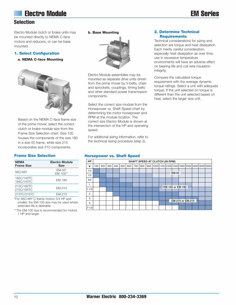
Electro Module clutch or brake units maybe mounted directly to NEMA C-facemotors and reducers, or can be basemounted.
Based on the NEMA C-face frame sizeof the prime mover, select the correctclutch or brake module size from theFrame Size Selection chart. Size 100houses the components of the size 180in a size 50 frame, while size 215incorporates size 210 components.
1. Select Configuration
a. NEMA C-face Mounting
2. Determine Technical Requirements
Technical considerations for sizing andselection are torque and heat dissipation.Each merits careful consideration,especially heat dissipation as over time,use in excessive temperatureenvironments will have an adverse effecton bearing life and coil wire insulationintegrity.
Compare the calculated torquerequirement with the average dynamictorque ratings. Select a unit with adequatetorque. If the unit selected on torque isdifferent than the unit selected based onheat, select the larger size unit.
Frame Size Selection
NEMA Electro ModuleFrame Size Size
56C/48YEM-50*
EM-100**
182C/143TCEM-180184C/145TC
213C/182TCEM-210215C/184TC
213TC/215TC EM-215
*For 56C/48Y C-frame motors 3/4 HP andsmaller, the EM-100 size may be used whereextended life is desirable.
**The EM-100 size is recommended for motors1 HP and larger.
b. Base Mounting
Electro Module assemblies may bemounted as separate drive units drivenfrom the prime mover by V-belts, chainand sprockets, couplings, timing beltsand other standard power transmissioncomponents.
Select the correct size module from theHorsepower vs. Shaft Speed chart bydetermining the motor horsepower andRPM at the module location. Thecorrect size Electro Module is shown atthe intersection of the HP and operatingspeed.
For additional sizing information, refer tothe technical sizing procedure (step 2).
Horsepower vs. Shaft Speed

EM Series Electro Module
Warner Electric 800-234-3369 11
0
6000
12000
18000
24000
30000
36000
0 3600900 1800 2700
Speed (RPM)
Hea
t D
issi
pat
ion
(ft.
lbs.
/min
.)
Size 210/215Maximum Speed 3600 RPM
250° F
200° F
0
3000
6000
9000
12000
15000
18000
0 3600900 1800 2700
Speed (RPM)
Hea
t D
issi
pat
ion
(ft.
lbs.
/min
.)
Size 100/180Maximum Speed 3600 RPM
250° F
200° F
0 36000
4000
8000
12000
2000
6000
10000
900 1800 2700
Speed (RPM)
Hea
t D
issi
pat
ion
(ft.
lbs.
/min
.)
Size 50Maximum Speed 3600 RPM
200° F
250° F
a. Heat Dissipation SizingFriction surfaces slip during the initialperiod of engagement and, as a result,heat is generated. The clutch/brakeselected must have a heat dissipationrating greater than the heat generatedby the application. Therefore, in highinertia or high cycle rate applications, itis necessary to check the heatdissipation carefully. Inertia, speed andcycle rate are the required parameters.
50% Current
16
Size 50Maximum Speed
3600 RPM Static Torque 16 lb.ft.
12
8
4
0
14
10
6
2
0 900 1800 2700 3600
100% Current
Dyn
amic
To
rque
(lb
.ft.
)
Speed Difference in RPM
32
Size 100/180Maximum Speed
3600 RPM Static Torque 30 lb.ft.
0
28
24
20
16
12
8
4
0
100% Current
50% Current
Dyn
amic
To
rque
(lb
.ft.
)
Speed Difference in RPM
900 1800 2700 3600
96
Size 210/215 Maximum Speed
3600 RPM Static Torque 95 lb.ft.
84
72
60
48
36
24
12
00
Dyn
amic
To
rque
(lb
.ft.
)
Speed Difference in RPM
900 1800 2700 3600
100% Current
50% Current
Heat dissipation requirement iscalculated as follows:
E = 1.7 x WR2 x (N/100)2 x F
where:
E = Heat (lb. ft./min.)
WR2 = Total reflected inertia at theclutch/brake shaft. Include theclutch/brake output inertia. (lb.ft.2)
N = Speed in revolutions per minute.(RPM)
F = Cycle rate in cycles per minute(CPM)
Compare the calculated heat generatedin the application to the unit ratingsusing the heat dissipation curves. Selectthe appropriate unit that has adequateheat dissipation ability.
b. Torque SizingFor most applications, the correct sizeclutch/brake can be selected from theHorsepower vs. Shaft Speed chart.
Determine the motor horsepower andthe RPM at the clutch/brake. Thecorrect size unit is shown at theintersection of horsepower and shaftspeed.
If the static torque requirements areknown, refer to the Specifications Tableto select a unit.
For some applications, the torquerequirement is determined by the timeallowed to accelerate and decelerate theload. (This time is generally specified inmilliseconds.) For these applications, itis necessary to determine the torquerequirement based on load inertia andthe time allowed for engagement.
The torque requirements are calculatedas follows:
T = (WR2 x N) / (308 x t)
where:
T = Average Dynamic Torque (lb. ft.)
WR2 = Total reflected inertia at theclutch/brake shaft. Include theclutch/brake output inertia. (lb. ft.2 )
N = Speed in revolutions per minute.(RPM)
t = Time allowed for the engagement(sec)
Heat Dissipation Curves
C-face Clutch/Power-on Brake Dynamic Torque Curves
0
6000
12000
18000
24000
30000
36000
0 3600900 1800 2700
Speed (RPM)
Hea
t D
issi
pat
ion
(ft.
lbs.
/min
.)
Size 210/215Maximum Speed 3600 RPM
250° F
200° F
0
3000
6000
9000
12000
15000
18000
0 3600900 1800 2700
Speed (RPM)
Hea
t D
issi
pat
ion
(ft.
lbs.
/min
.)
Size 100/180Maximum Speed 3600 RPM
250° F
200° F
0 36000
4000
8000
12000
2000
6000
10000
900 1800 2700
Speed (RPM)
Hea
t D
issi
pat
ion
(ft.
lbs.
/min
.)
Size 50Maximum Speed 3600 RPM
200° F
250° F
0
6000
12000
18000
24000
30000
36000
0 3600900 1800 2700
Speed (RPM)
Hea
t D
issi
pat
ion
(ft.
lbs.
/min
.)
Size 210/215Maximum Speed 3600 RPM
250° F
200° F
0
3000
6000
9000
12000
15000
18000
0 3600900 1800 2700
Speed (RPM)
Hea
t D
issi
pat
ion
(ft.
lbs.
/min
.)
Size 100/180Maximum Speed 3600 RPM
250° F
200° F
0 36000
4000
8000
12000
2000
6000
10000
900 1800 2700
Speed (RPM)
Hea
t D
issi
pat
ion
(ft.
lbs.
/min
.)
Size 50Maximum Speed 3600 RPM
200° F
250° F
50% Current
16
Size 50Maximum Speed
3600 RPM Static Torque 16 lb.ft.
12
8
4
0
14
10
6
2
0 900 1800 2700 3600
100% Current
Dyn
amic
To
rque
(lb
.ft.
)
Speed Difference in RPM
32
Size 100/180Maximum Speed
3600 RPM Static Torque 30 lb.ft.
0
28
24
20
16
12
8
4
0
100% Current
50% Current
Dyn
amic
To
rque
(lb
.ft.
)
Speed Difference in RPM
900 1800 2700 3600
96
Size 210/215 Maximum Speed
3600 RPM Static Torque 95 lb.ft.
84
72
60
48
36
24
12
00
Dyn
amic
To
rque
(lb
.ft.
)
Speed Difference in RPM
900 1800 2700 3600
100% Current
50% Current
50% Current
16
Size 50Maximum Speed
3600 RPM Static Torque 16 lb.ft.
12
8
4
0
14
10
6
2
0 900 1800 2700 3600
100% Current
Dyn
amic
To
rque
(lb
.ft.
)
Speed Difference in RPM
32
Size 100/180Maximum Speed
3600 RPM Static Torque 30 lb.ft.
0
28
24
20
16
12
8
4
0
100% Current
50% Current
Dyn
amic
To
rque
(lb
.ft.
)
Speed Difference in RPM
900 1800 2700 3600
96
Size 210/215 Maximum Speed
3600 RPM Static Torque 95 lb.ft.
84
72
60
48
36
24
12
00
Dyn
amic
To
rque
(lb
.ft.
)
Speed Difference in RPM
900 1800 2700 3600
100% Current
50% Current

Electro Module EM Series
12 Warner Electric 800-234-3369
Specifications
EM Size Static Torque lb. ft. Maximum RPM Voltage D.C.50 16 3600 6, 24, or 90
100 30 3600 6, 24, or 90
180 30 3600 6, 24, or 90
210 95 3600 6, 24, or 90
215 95 3600 90
3. AccessoriesWarner Electric Electro Modules can befitted with several accessories to extendtheir capacity and ease of mounting.
a. Conduit BoxNEMA 4 and UL listed, available instandard and washdown versions.
a. Mounting BracketsTwo styles of mounting brackets areavailable for simplified installation. The base mount is used with the 20/30and 30/40 configurations. A motormount is also available and providessturdy support for 10/20 and 10/40units and motor.
4. Select Control Warner Electric manufactures clutch/brakecontrols to meet several system functionsincluding:
• On/Off
• Torque adjust
• Over excitation
• Position loop
Many requirements beyond function canimpact control selection. See the ControlsSection on page 141 for completeinformation.

Example
EM-180 20 – 30 90 Volt
Input Clutch
Brake
Size
EM Series Electro Module
Warner Electric 800-234-3369 13
Ordering Information
Part Numbers
Description Model No. Voltage DC Part No.10 EM-50-10 6 5370-270-020Motor Clutch EM-50-10 24 5370-270-030Module EM-50-10 90 5370-270-015
EM-100-10 6 5370-270-045EM-100-10 24 5370-270-056EM-100-10 90 5370-270-046
EM-180-10 6 5370-270-021EM-180-10 24 5370-270-055EM-180-10 90 5370-270-017
EM-210-10 6 5371-270-011EM-210-10 24 5371-270-027EM-210-10 90 5371-270-009
20 EM-50-20 6 5370-169-043Brake EM-50-20 24 5370-169-045Module EM-50-20 90 5370-169-042
EM-100-20 6 5370-169-040EM-100-20 24 5370-169-072EM-100-20 90 5370-169-041
EM-180-20 6 5370-169-050EM-180-20 24 5370-169-071EM-180-20 90 5370-169-051
EM-210-20 6 5371-169-022EM-210-20 24 5371-169-034EM-210-20 90 5371-169-023
EM-215-20 90 5371-169-076
20MB EM-50-20MB 6 5370-169-047Motor EM-50-20MB 24 5370-169-062Brake EM-50-20MB 90 5370-169-048
EM-180-20MB 6 5370-169-053EM-180-20MB 24 5370-169-073EM-180-20MB 90 5370-169-054
EM-210-20MB 6 5371-169-025EM-210-20MB 24 5371-169-035EM-210-20MB 90 5371-169-026
30 EM-50-30 6 5370-270-019Input Clutch EM-50-30 24 5370-270-052Module EM-50-30 90 5370-270-016
EM-100-30 6 5370-270-047EM-100-30 24 5370-270-054EM-100-30 90 5370-270-048
EM-180-30 6 5370-270-049EM-180-30 24 5370-270-053EM-180-30 90 5370-270-050
EM-210-30 6 5371-270-023EM-210-30 24 5371-270-026EM-210-30 90 5371-270-024
40 EM-50-40 5370-536-008Output EM-100-40 5370-536-007Clutch EM-180-40 5370-536-009Module EM-210-40 5371-536-005
Accessories
Description EM Size Part No.
Conduit BoxEM series
5370-101-042All sizes
Base Mount Kit50/100 5370-101-004
for 2030, 3040180 5370-101-002
210/215 5371-101-001
Motor Mount Kit50/100 5370-101-010
for 20, 1020, 1040180 5370-101-012
210/215 5371-101-012
How to Order
Motor or Reducer MountedSimply combine the size number with the configuration of themodular combination from page 9.
Specify voltage and whether 20 brake module is power-on (20)or electrically released (20FBB). See chart for specific partnumbers. See pages 130-133 for electrically released models.Order optional conduit box if desired.
Base MountedSimply combine the size number with the configuration of themodular combination from page 9.
Specify voltage and whether 20 brake module is power-on (20)or electrically released (20FBB). See chart for specific partnumbers. Order optional conduit box if desired.
Example
EM-180 20 – 30 - B 90 Volt
Base
Input Clutch
Brake
Size
Select Appropriate Power Supply/Control. See the ControlsSection beginning on page 141.

Electro Module EM Series
14 Warner Electric 800-234-3369
Specifications
Model Size Voltage DC Static Torque lb. ft. Max. RPM Inertia–WR2 (lb.ft.2) Weight (lbs) NEMA Frame Size
50 6, 24, 90 16 3600 .020 3.4 56C/48Y*
100 6, 24, 90 30 3600 .046 5.1 56C/48Y**
180 6, 24, 90 30 3600 .046 5.1182C/143TC184C/145TC
210 6, 24, 90 95 3600 .188 9.1213C/182TC215C/184TC
All dimensions are nominal, unless otherwise noted.
Size A Pilot Dia. B Dia. C D Dia. E Max. F Max. AA BB Min. CC DD Key
50 4.500 .625 .813 6.750 .599 1.563 30° 36 45° 3/16 x 3/16
100 4.500 .625 .813 6.750 .599 1.563 30° 36 45° 3/16 x 3/16
180 4.500 .875 .813 6.750 .599 1.563 30° 36 45° 3/16 x 3/16
210 8.500 1.125 .703 9.250 .625 1.313 25° 36 45° 1/4 x 1/4
FE
A
B
CElectricalConnection
D
1/2" NPT
Typical End View
AA
BB
CC
DD
1/2" NPT
10 Motor Clutch Module
* For 56C/48Y Frame motors 3/4 HP and smaller the EM-100 sizemay be used where extended life is desirable.
** EM-100 size is recommended for motors 1 HP and larger.
For NEMA Standard frame sizes, see page 137.

EM Series Electro Module
Warner Electric 800-234-3369 15
20 Brake Module20MB Brake Module
All dimensions are nominal, unless otherwise noted.
Size A B C D E F G H I J K L BB DDMax. Max. Max. Dia. Dia. Keyway Min. Pilot Dia. Dia. AA Min. CC Key
3/8-16 UNC-2A 3/16 X50 5.188 3.125 .500 1.000 .156 Equally Spaced 6.688 .625 3/16 x 1.813 4.500 .625 30° 36 45° 3/16 x 3/16
(4) on 5.875 D. 1-3/8
3/8-16 UNC-2A 3/16 X100 5.188 3.125 .500 1.000 .156 Equally Spaced 6.688 .625 3/16 x 1.813 4.500 .625 30° 36 45° 3/16 x 3/16
(4) on 5.875 D. 1-3/8
3/8-16 UNC-2A 3/16 X180 5.266 3.125 .500 1.000 .156 Equally Spaced 6.688 .875 3/16 x 1.891 4.500 .875 30° 36 45° 3/16 x 3/16
(4) on 5.875 D. 1-3/8
1/2-16 UNC-2A 1/4 X210 7.578 4.609 .594 1.500 .313 Equally Spaced 9.344 1.125 1/4 x 2.500 8.500 1.125 25° 36 45° 1/4 x 1/4
(4) on 7.250 D. 2
1/2-16 UNC-2A 1/4 X215 8.078 4.609 .594 1.500 .313 Equally Spaced 9.344 1.375 1/4 x 3.000 8.500 1.375 25° 36 45° 5/16 x 5/16
(4) on 7.250 D. 2
Specifications
Model Size Voltage DC Static Torque lb. ft. Max. RPM Armatures Inertia–WR2 Arm. Hub Shaft Weight (lbs) NEMA Frame Size50 6, 24, 90 16 3600 .014 .002 .001 6.6 56C/48Y*
100 6, 24, 90 30 3600 .036 .003 .002 8.1 56C/48Y**
180 6, 24, 90 30 3600 .036 .003 .002 8.1182C/143TC184C/145TC
210 6, 24, 90 95 3600 .162 .021 .017 21.5213C/182TC215C/184TC
215 90 95 3600 .162 .021 .019 22 213TC/215TC***
Typical End View
AA
BB
CC
DD
1/2" NPT
SeeNote B
ElectricalConnection
See Note A
H
G
F
C D EB
A
J
L
I
K
Notes:A. Same overall dimensions apply to
Motor Brakes. 20MB Module doesnot have an output shaft.
B. Clutch armature only applies to EM-20.
* For 56C/48Y Frame motors 3/4 HP and smaller the EM-100 sizemay be used where extended life is desirable.
** EM-100 size is recommended for motors 1 HP and larger.
*** For 7-1/2 HP max.
For NEMA standard frame sizes, see page 137.

Electro Module EM Series
16 Warner Electric 800-234-3369
30 Input Clutch Module
All dimensions are nominal, unless otherwise noted.
Size A B C D E F G I AA BB CC DD`Max. Min. Pilot Dia. Dia. Max. H Dia. Min. Key
50 1.000 1.563/16 x
1.813 4.500 .625 4.328 2.266 6.688 30° 36 45° 3/16 x 3/163/16 x 1-3/8
100 1.000 1.563/16 x
1.813 4.500 .625 4.328 2.266 6.688 30° 36 45° 3/16 x 3/163/16 x 1-3/8
180 1.000 1.563/16 x
1.891 4.500 .875 4.391 2.266 6.688 30° 36 45° 3/16 x 3/163/16 x 1-3/8
210 1.500 .312 1/4 x 1/4 2.500 8.500 1.125 5.391 2.438 9.219 25° 36 45° 1/4 x 1/4
Specifications
Inertia–WR2
Model Size Voltage DC Static Torque lb. ft. Max. RPM Rotor Shaft Weight (lbs) NEMA Frame Size50 6, 24, 90 16 3600 .020 .001 6.4 56C/48Y*
100 6, 24, 90 30 3600 .046 .002 8.4 56C/48Y**
180 6, 24, 90 30 3600 .046 .002 8.4182C/143TC184C/145TC
210 6, 24, 90 95 3600 .188 .017 19.8213C/182TC215C/184TC
Typical End View
AA
BB
CC
DD
1/2" NPT
G
ABH
D
E
F
C
Electrical Connection
I
* For 56C/48Y Frame motors 3/4 HP and smaller the EM-100 sizemay be used where extended life is desirable.
** EM-100 size is recommended for motors 1 HP and larger.
For NEMA standard frame sizes, see page 137.

EM Series Electro Module
Warner Electric 800-234-3369 17
40 Output Clutch Module
Specifications
Inertia–WR2
Model Size Voltage DC Static Torque lb. ft. Max. RPM Armatures Arm. Hub Shaft Weight (lbs) NEMA Frame Size50 6, 24, 90 16 3600 .007 .002 .001 4.9 56C/48Y*
100 6, 24, 90 30 3600 .018 .003 .002 5.2 56C/48Y**
180 6, 24, 90 30 3600 .018 .003 .002 5.2182C/143TC184C/145TC
210 6, 24, 90 95 3600 .181 .021 .017 15.2213C/182TC215C/184TC
All dimensions are nominal, unless otherwise noted.
Size A B C D E F G H AA BB CC DDMax. Max. Dia. Min. Pilot Dia. Dia. Min. Key
50 5.188 3.125 .156 6.6873/16 x
1.813 4.500 .625 30° 36 45° 3/16 x 3/163/16 x 1-3/8
100 5.188 3.125 .156 6.6873/16 x
1.813 4.500 .625 30° 36 45° 3/16 x 3/163/16 x 1-3/8
180 5.266 3.125 .313 6.6873/16 x
1.891 4.500 .875 30° 36 45° 3/16 x 3/163/16 x 1-3/8
210 7.578 4.609 .313 9.3441/4 x
2.500 8.500 1.125 25° 36 45° 1/4 x 1/41/4 x 2
Typical End View
AA
BB
CC
DD
1/2" NPT
D
CB
A
F
H
GE
* For 56C/48Y Frame motors 3/4 HP and smaller the EM-100 sizemay be used where extended life is desirable.
** EM-100 size is recommended for motors 1 HP and larger.
For NEMA standard frame sizes, see page 137.

All dimensions are nominal, unless otherwise noted.
Size A B C D E I J K L M N O NEMA Frame Size
50 6.750 4.844 1.813 6.750 .625 6.688 3.500 6.844 2.000 6.000 .500 5.000 56C/48Y*
100 6.750 4.844 1.813 6.750 .625 6.688 3.500 6.844 2.000 6.000 .500 5.000 56C/48Y**
180 6.828 4.844 1.891 6.750 .875 6.688 4.500 7.844 3.000 6.625 .813 5.000182C/143TC184C/145TC
210 8.891 5.922 2.500 9.250 1.125 9.688 5.250 9.906 3.375 9.000 .625 7.750213C/182TC215C/184TC
Electro Module EM Series
18 Warner Electric 800-234-3369
EM-10/20 Clutch/Brake Combination
A
D
B
C
E
10Motor Clutch
Module
20Brake
Module
NEED REF.
* For 56C/48Y Frame motors 3/4 HP and smaller the EM-100 sizemay be used where extended life is desirable.
** EM-100 size is recommended for motors 1 HP and larger.
For NEMA standard frame sizes, see page 137.
D
C
H
F G
E
F
H
D
C
A
B
M
ON N
J
K
L
I
30Input Clutch
Module
20Brake
Module
Note: Mounting base is optional and is ordered separately.Motor Clutch (10) and Output Clutch (20) are ordered separately.
For use with 1020, 1040, 20, 20 FBB and 1020 FBC Combinations.
Size A B C D E F Part No.50/100 9.25 8.25 11.00 8.000 3.50 .797 x .406 5370-101-010
180 9.25 8.25 11.00 8.000 4.50 .797 x .406 5370-101-012/5370-101-047
210/215 11.50 10.50 12.00 9.000 5.25 .750 x .406 5371-101-012/5371-101-025
Motor Mount (M)
A
E
DC
B
F (4) slots

EM Series Electro Module
Warner Electric 800-234-3369 19
EM-10/40 Motor Clutch/Output Clutch Combination
A
D
B10
Motor ClutchModule
40Output Clutch
Module
C
E
NEED REF.
All dimensions are nominal, unless otherwise noted.
Size A B C D E I J K L M N O NEMA Frame Size
50 6.750 4.844 1.813 6.750 .625 6.688 3.500 6.844 2.000 6.000 .500 5.000 56C/48Y*
100 6.750 4.844 1.813 6.750 .625 6.688 3.500 6.844 2.000 6.000 .500 5.000 56C/48Y**
180 6.828 4.844 1.891 6.750 .875 6.688 4.500 7.844 3.000 6.625 .813 5.000182C/143TC184C/145TC
210 8.891 5.922 2.500 9.250 1.125 9.688 5.250 9.906 3.375 9.000 .625 7.750213C/182TC215C/184TC
* For 56C/48Y Frame motors 3/4 HP and smaller the EM-100 sizemay be used where extended life is desirable.
** EM-100 size is recommended for motors 1 HP and larger.
For NEMA standard frame sizes, see page 137.
D
C
H
F G
E
F
H
D
C
A
B
M
ON N
J
K
L
I
30Input Clutch
Module
20Brake
Module
Note: Mounting base is optional and is ordered separately.Motor Clutch (10) and Output Clutch (40) are orderedseparately.
For use with 1020, 1040, 20, 20 FBB and 1020 FBC Combinations.
Size A B C D E F Part No.50/100 9.25 8.25 11.00 8.000 3.50 .797 x .406 5370-101-010
180 9.25 8.25 11.00 8.000 4.50 .797 x .406 5370-101-012/5370-101-047
210/215 11.50 10.50 12.00 9.000 5.25 .750 x .406 5371-101-012/5371-101-025
Motor Mount (M)
A
E
DC
B
F (4) slots

Electro Module EM Series
20 Warner Electric 800-234-3369
EM-20/30 Brake/Input Clutch CombinationEM-20/30-B Brake/Input Clutch Combination – Base Mounted
All dimensions are nominal, unless otherwise noted.
Size A B C Min. D E F G H I J K L M N O
50 5.719 9.516 1.813 .625 5.672 .844 4.000 .344 6.688 3.500 6.844 2.000 6.000 .500 5.000
100 5.719 9.516 1.813 .625 5.672 .844 4.000 .344 6.688 3.500 6.844 2.000 6.000 .500 5.000
180 5.719 9.656 1.891 .875 5.672 .844 4.000 .344 6.688 4.500 7.844 3.000 6.625 .813 5.000
210 7.719 12.969 2.500 1.125 8.203 1.094 6.000 .438 9.688 5.250 9.906 3.375 9.000 .625 7.750
D
C
H
F G
E
F
H
D
C
A
B
M
ON N
J
K
L
I
30Input Clutch
Module
20Brake
Module
Note: Mounting base is optional and is ordered separately.Input Clutch (30) module and Brake Module (20) areordered separately.
For use with 2030 and 3040 units.
Size A B C D F E G Part No.50/100 6.000 5.000 5.672 4.000 .750 X .406 3.500 2.000 5370-101-004
180 6.625 5.000 5.672 4.000 .750 X .406 4.500 3.000 5370-101-002/5370-101-049
210/215 9.000 7.750 8.203 6.000 .750 X .531 5.250 3.385 5371-101-001/5371-101-026
Base (B)
B
D CA
G
F (4) Slots
E

EM Series Electro Module
Warner Electric 800-234-3369 21
EM-30/40 Input Clutch/Output Clutch CombinationEM-30/40 Input Clutch/Output Clutch Combination – Base Mounted
All dimensions are nominal, unless otherwise noted.
Size A B C Min. D E F G H I J K L M N O
50 5.719 9.516 1.813 .625 5.672 .844 4.000 .344 6.688 3.500 6.844 2.000 6.000 .500 5.000
100 5.719 9.516 1.813 .625 5.672 .844 4.000 .344 6.688 3.500 6.844 2.000 6.000 .500 5.000
180 5.719 9.656 1.891 .875 5.672 .844 4.000 .344 6.688 4.500 7.844 3.000 6.625 .813 5.000
210 7.719 12.969 2.500 1.125 8.203 1.094 6.000 .438 9.688 5.250 9.906 3.375 9.000 .625 7.750
B
A
D
C
F G
E
H HF
C
D
30Input Clutch
Module
40OutputClutch
M
ON N
J
K
L
I
Note: Mounting base is optional and is ordered separately.Input Clutch (30) module and Output Clutch (40) are orderedseparately.
For use with 2030 and 3040 units.
Size A B C D F E G Part No.50/100 6.000 5.000 5.672 4.000 .750 X .406 3.500 2.000 5370-101-004
180 6.625 5.000 5.672 4.000 .750 X .406 4.500 3.000 5370-101-002/5370-101-049
210/215 9.000 7.750 8.203 6.000 .750 X .531 5.250 3.385 5371-101-001/5371-101-026
Base (B)
UM-2030-C Mtg Kit
B
D CA
G
F (4) Slots
E

UniModule UM Series
22 Warner Electric 800-234-3369
UniModules offer the ultimate inClutch/Brake performance andconvenience. UniModules offerthe same performance as EM’swithout the assembly required.
Completely pre-assembled one-piece clutch and clutch/brakepackages in five sizes. Can bemotor or reducer mounted orused as a separate drive unitpowered by a prime mover.
Pre-assembled, pre-aligned,and pre-burnished at thefactory for rated torque directlyout-of-the-box.
Pre-assembled, C-face Clutches and Brakes
• Easy installation
• Available with standard power-on andelectrically released power-off brake units
• Fan cooled for high cycle rate operation
• Maintenance Free
• Available in 50, 100, 180, 210, and 215sizes. NEMA C-face design
• UL rated, CSA certified
• Can be applied with control fitted asstandard
• Bearing mounted clutch rotor easesassembly alignment
• Single access hole for all wires
Easy Installation
1. Slide UniModule on to motor shaft.
2. Position vent holes to bottom andinsert four capscrews.
3. Use Allen wrench to tighten rotorset screws.
High torque, long life,asbestos free friction material
Finned designfor maximumheat dissipation
Heavy duty bearingsmaintain tight concentricityand running efficiency
NEMA C-facecompatible design
Single conduit entrance
Autogaps®automaticallyadjust for wear
Bearing mounted rotor
Easy set screw access
Completely sealed coils
Fan cooled forlong life andconsistent performance
1.3.
2.

UM Series UniModule
Warner Electric 800-234-3369 23
UniModule Combinations
1040Motor Clutch/Output ClutchUse for clutch only applications. Hashollow bore input for mounting directly toC-face motors. Shaft and C-face on outputside of unit accommodates reducer,parallel drive or coupling. Motor Clutch isfan cooled for long life and consistentperformance. Basic components are field,rotor and armature. See page 29.
3040Input Clutch/Output ClutchUse for clutch only applications. Featuresdual C-faces and shafts. Unit input fromparallel drive or coupling. Output toreducer. Input Clutch is fan cooled and hassealed coils. Twin bearing mounted shaftmaintains tight concentricities. The OutputClutch utilizes Autogaps™ whichautomatically adjust armature for wear.Basic components are field, rotor andarmature. See page 31.
3040-BInput Clutch/Output Clutch – withAccessory Base MountingBase mounting allows the clutch unit to beutilized as a separate drive unit. Attachwith pulleys, sprockets, etc. See page 31.
1020Motor Clutch/BrakeUse for clutch/brake applications. Hashollow bore input for mounting directly to C-face motors. Brake shaft and C-face onoutput side accommodate a reducer,parallel drive or coupling. Basiccomponents: field, rotor, 2 armatures andpower-on magnet. See page 28.
1020-FBCMotor Clutch/Electrically ReleasedBrakeUse for clutch/power-off brakeapplications. Has clutch input and brakeon output side. Employs powerfulpermanent magnets for maximum torquewhen power is removed from the brakecoil. Basic components are field, rotor, 2armatures and power-off magnet. Seepage 119 for specifications.
2030Input Clutch/BrakeUse for clutch/brake applications. Featuresdual C-faces and shafts. Input from paralleldrive or coupling. Output to reducer. Basiccomponents are field, rotor, 2 armaturesand power-on magnet. See page 30.
2030-FBCInput Clutch/Electrically Released BrakeUse for clutch/power-off brakeapplications. Has shafts on input andoutput sides. When electrical power isapplied to the brake coil the brakereleases. Ideal for dynamic cyclingoperations. Basic components are field,rotor, 2 armatures and power-off magnet.See page 119 for specifications.
2030-BInput Clutch/Brake – withAccessory Base MountingBase mounting allows the clutch/brakeunits to be utilized as a separate drive unit.Attach with pulleys, sprockets, etc. See page 30.
2030-FBC-BInput Clutch/Electrically ReleasedBrake with Accessory BaseMountingSee page 130 for Electrically ReleasedBrake specifications.
Clutch/Brake Combinations
Clutch Combinations

UniModule UM Series
24 Warner Electric 800-234-3369
Selection
Frame Size Selection
NEMA Frame Size UniModule Size
56C/48Y UM-50*UM-100**
182C/143TC UM-180184C/145TC213C/182TC UM-210215C/184TC213TC/215TC UM-215
UniModule clutch, brake and clutch/brakeunits may be mounted directly to NEMAC-face motors and reducers, or can bebase mounted.
1. Select Configuration
a. NEMA C-face Mounting
To select the correct UniModulepackage, determine the NEMA framesize of your motor and/or reducer, andchoose the corresponding sizeUniModule from the Frame SizeSelection chart.
Size UM-100 modules utilize a 5/8"diameter shaft to fit 56C/48Y motorframes with components of UM-180units for higher torque and heatdissipation capacity than the UM-50.
UM-100 modules are available in 1020and 2030 clutch/brake and 1040 and3040 clutch configurations. For C-facemounting, select either a 1020clutch/brake or a 1040 clutchconfiguration. The 2030 and 3040configurations are for base mounting.
b. Base Mounting
* For 56C/48Y Frame motors 3/4 HP andsmaller the UM-100 size may be used whereextended life is desirable.
** UM-100 size is recommended for motors 1HP and larger.
UniModule assemblies may be mountedas separate drive units driven from theprime mover by V-belts, chain andsprockets, couplings, timing belts andother standard power transmissioncomponents.
Select the correct size module from theHorsepower vs. Shaft Speed chart bydetermining the motor horsepower andRPM at the module location. The correctsize UniModule is shown at theintersection of the HP and operatingspeed.
For additional sizing information, refer tothe technical sizing procedure (step 2).
UM HP/Shaft Speed Chart11/14/99page 10
SHAFT SPEED AT CLUTCH (IN RPM)
100 600 1000 1100 1200 1500 1800 2000 2400 3000 3600
1/4
1/2
3/4
1
1-1/2
2
3
5
7-1/2
HP
UM -50
UM -100 or UM -180
UM -210 0R UM -215
UM -215
Horsepower vs. Shaft Speed
200 300 400 500 700 800 900
Horsepower vs. Shaft Speed
2. Determine Technical Requirements
Technical considerations for sizing andselection are torque and heat dissipation.Each merits careful consideration,especially heat dissipation as over time,use in excessive temperatureenvironments will have an adverse effecton bearing life and coil wire insulationintegrity.
Compare the calculated torquerequirement with the average dynamictorque ratings. Select a unit with adequatetorque. If the unit selected on torque isdifferent than the unit selected based onheat, select the larger size unit.

UM Series UniModule
Warner Electric 800-234-3369 25
a. Heat Dissipation Sizing Friction surfaces slip during the initialperiod of engagement and, as a result,heat is generated. The clutch/brakeselected must have a heat dissipationrating greater than the heat generatedby the application. Therefore, in highinertia or high cycle rate applications, itis necessary to check the heatdissipation carefully. Inertia, speed andcycle rate are the required parameters.
Heat dissipation requirement iscalculated as follows:
E = 1.7 x WR2 x (N/100)2 x F
where:
E = Heat (lb. ft./min.)
WR2 = Total reflected inertia at theclutch/brake shaft. Include theclutch/brake output inertia. (lb.ft.2 )
N = Speed in revolutions per minute.(RPM)
F = Cycle rate in cycles per minute(CPM)
Compare the calculated heat generatedin the application to the unit ratingsusing the heat dissipation curves. Selectthe appropriate unit that has adequateheat dissipation ability.
0
6000
12000
18000
24000
30000
36000
0 3600900 1800 2700
Speed (RPM)
Hea
t D
issi
pat
ion
(ft.
lbs.
/min
.)
Size 210/215Maximum Speed 3600 RPM
250° F
200° F
0
3000
6000
9000
12000
15000
18000
0 3600900 1800 2700
Speed (RPM)
Hea
t D
issi
pat
ion
(ft.
lbs.
/min
.)
Size 100/180Maximum Speed 3600 RPM
250° F
200° F
0 36000
4000
8000
12000
2000
6000
10000
900 1800 2700
Speed (RPM)
Hea
t D
issi
pat
ion
(ft.
lbs.
/min
.)
Size 50Maximum Speed 3600 RPM
200° F
250° F
50% Current
16
Size 50Maximum Speed
3600 RPM Static Torque 16 lb.ft.
12
8
4
0
14
10
6
2
0 900 1800 2700 3600
100% Current
Dyn
amic
To
rque
(lb
.ft.
)
Speed Difference in RPM
32
Size 100/180Maximum Speed
3600 RPM Static Torque 30 lb.ft.
0
28
24
20
16
12
8
4
0
100% Current
50% Current
Dyn
amic
To
rque
(lb
.ft.
)
Speed Difference in RPM
900 1800 2700 3600
96
Size 210/215 Maximum Speed
3600 RPM Static Torque 95 lb.ft.
84
72
60
48
36
24
12
00
Dyn
amic
To
rque
(lb
.ft.
)
Speed Difference in RPM
900 1800 2700 3600
100% Current
50% Current
b. Torque SizingFor most applications, the correct sizeclutch/brake can be selected from theHorsepower vs. Shaft Speed chartlocated at the bottom of this page.Determine the motor horsepower andthe RPM at the clutch/brake. Thecorrect size unit is shown at theintersection of horsepower and shaftspeed.
If the static torque requirements areknown, refer to the technical ratingschart to select a unit.
For some applications, the torquerequirement is determined by the timeallowed to accelerate and decelerate theload. (This time is generally specified inmilliseconds.) For these applications, itis necessary to determine the torquerequirement based on load inertia andthe time allowed for engagement.
The torque requirements are calculatedas follows:
T = (WR2 x N) / (308 x t)
where:
T = Average Dynamic Torque (lb. ft.)
WR2 = Total reflected inertia at theclutch/brake shaft. Include theclutch/brake output inertia. (lb. ft.2 )
N = Speed in revolutions per minute.(RPM)
t = Time allowed for the engagement(sec)
Heat Dissipation Curves
C-face Clutch/Power-on Brake Dynamic Torque Curves
0
6000
12000
18000
24000
30000
36000
0 3600900 1800 2700
Speed (RPM)
Hea
t D
issi
pat
ion
(ft.
lbs.
/min
.)
Size 210/215Maximum Speed 3600 RPM
250° F
200° F
0
3000
6000
9000
12000
15000
18000
0 3600900 1800 2700
Speed (RPM)
Hea
t D
issi
pat
ion
(ft.
lbs.
/min
.)
Size 100/180Maximum Speed 3600 RPM
250° F
200° F
0 36000
4000
8000
12000
2000
6000
10000
900 1800 2700
Speed (RPM)
Hea
t D
issi
pat
ion
(ft.
lbs.
/min
.)
Size 50Maximum Speed 3600 RPM
200° F
250° F
0
6000
12000
18000
24000
30000
36000
0 3600900 1800 2700
Speed (RPM)
Hea
t D
issi
pat
ion
(ft.
lbs.
/min
.)
Size 210/215Maximum Speed 3600 RPM
250° F
200° F
0
3000
6000
9000
12000
15000
18000
0 3600900 1800 2700
Speed (RPM)
Hea
t D
issi
pat
ion
(ft.
lbs.
/min
.)
Size 100/180Maximum Speed 3600 RPM
250° F
200° F
0 36000
4000
8000
12000
2000
6000
10000
900 1800 2700
Speed (RPM)
Hea
t D
issi
pat
ion
(ft.
lbs.
/min
.)
Size 50Maximum Speed 3600 RPM
200° F
250° F
50% Current
16
Size 50Maximum Speed
3600 RPM Static Torque 16 lb.ft.
12
8
4
0
14
10
6
2
0 900 1800 2700 3600
100% Current
Dyn
amic
To
rque
(lb
.ft.
)
Speed Difference in RPM
32
Size 100/180Maximum Speed
3600 RPM Static Torque 30 lb.ft.
0
28
24
20
16
12
8
4
0
100% Current
50% Current
Dyn
amic
To
rque
(lb
.ft.
)
Speed Difference in RPM
900 1800 2700 3600
96
Size 210/215 Maximum Speed
3600 RPM Static Torque 95 lb.ft.
84
72
60
48
36
24
12
00
Dyn
amic
To
rque
(lb
.ft.
)
Speed Difference in RPM
900 1800 2700 3600
100% Current
50% Current
50% Current
16
Size 50Maximum Speed
3600 RPM Static Torque 16 lb.ft.
12
8
4
0
14
10
6
2
0 900 1800 2700 3600
100% Current
Dyn
amic
To
rque
(lb
.ft.
)
Speed Difference in RPM
32
Size 100/180Maximum Speed
3600 RPM Static Torque 30 lb.ft.
0
28
24
20
16
12
8
4
0
100% Current
50% Current
Dyn
amic
To
rque
(lb
.ft.
)
Speed Difference in RPM
900 1800 2700 3600
96
Size 210/215 Maximum Speed
3600 RPM Static Torque 95 lb.ft.
84
72
60
48
36
24
12
00
Dyn
amic
To
rque
(lb
.ft.
)
Speed Difference in RPM
900 1800 2700 3600
100% Current
50% Current

UniModule UM Series
26 Warner Electric 800-234-3369
Specifications
UM Size Static Torque lb. ft. Maximum RPM Voltage DC50 16 3600 6, 24, or 90
100 30 3600 6, 24, or 90
180 30 3600 6, 24, or 90
210 95 3600 6, 24, or 90
215 95 3600 6, 24, or 90
3. AccessoriesWarner Electric UniModules can be fittedwith several accessories to extend theircapacity and ease of mounting.
a. Conduit BoxNEMA 4 and UL listed, available instandard and washdown versions.
b. Mounting BracketsTwo styles of mounting brackets areavailable for simplified installation.The base mount is used with the 2030 and 3040 configurations. A motormount is also available and providessturdy support for 1020 and 1040 units and a motor.
4. Select ControlWarner Electric manufactures clutch/brakecontrols to meet several system functionsincluding:
• On/Off
• Torque adjust
• Over excitation
• Position loop
Many requirements beyond function canimpact control selection. See the ControlsSection on page 141 for completeinformation.

Part Numbers
Configuration Model No. Voltage D.C. Part No.1020 UM-50-1020 6 5370-273-016
UM-50-1020 24 5370-273-018UM-50-1020 90 5370-273-017UM-100-1020 6 5370-273-026UM-100-1020 24 5370-273-028UM-100-1020 90 5370-273-027
UM-180-1020 6 5370-273-006UM-180-1020 24 5370-273-008UM-180-1020 90 5370-273-007UM-210-1020 6 5371-273-002UM-210-1020 24 5371-273-004UM-210-1020 90 5371-273-003UM-215-1020 6 5371-273-076
Motor UM-215-1020 24 5371-273-077Clutch/Brake UM-215-1020 90 5371-273-078
UM-1020 w/Pre-installed controlUM50-1020 w/CBC-150-1 90 5370-9UM100-1020 w/CBC-150-1 90 5370-10UM180-1020 w/CBC-150-1 90 5370-273-122UM210-1020 w/CBC-150-1 90 5371-4UM215-1020 w/CBC-150-1 90 5371-273-090
1040 UM-50-1040 6 5370-271-004UM-50-1040 24 5370-271-006UM-50-1040 90 5370-271-005UM-100-1040 6 5370-271-024UM-100-1040 24 5370-271-026UM-100-1040 90 5370-271-025UM-180-1040 6 5370-271-014UM-180-1040 24 5370-271-016UM-180-1040 90 5370-271-015UM-210-1040 6 5371-271-002UM-210-1040 24 5371-271-004UM-210-1040 90 5371-271-003UM-215-1040 6 5371-271-026
Motor Clutch UM-215-1040 24 5371-271-027Output Clutch UM-215-1040 90 5371-271-028
2030 UM-50-2030 6 5370-273-021UM-50-2030 24 5370-273-023UM-50-2030 90 5370-273-022UM-100-2030 6 5370-273-031UM-100-2030 24 5370-273-033UM-100-2030 90 5370-273-032UM-180-2030 6 5370-273-011UM-180-2030 24 5370-273-013UM-180-2030 90 5370-273-012UM-210-2030 6 5371-273-007UM-210-2030 24 5371-273-009UM-210-2030 90 5371-273-008UM-215-2030 6 5371-273-043
Input UM-215-2030 24 5371-273-044Clutch/Brake UM-215-2030 90 5371-273-045
3040 UM-50-3040 6 5370-271-009UM-50-3040 24 5370-271-011UM-50-3040 90 5370-271-010UM-100-3040 6 5370-271-029UM-100-3040 24 5370-271-031UM-100-3040 90 5370-271-030UM-180-3040 6 5370-271-019UM-180-3040 24 5370-271-021UM-180-3040 90 5370-271-020UM-210-3040 6 5371-271-007UM-210-3040 24 5371-271-009UM-210-3040 90 5371-271-008UM-215-3040 6 5371-271-021
Input Clutch UM-215-3040 24 5371-271-022Output Clutch UM-215-3040 90 5371-271-023
UM Series UniModule
Warner Electric 800-234-3369 27
Ordering Information
Accessories
Description UM Size Part No.Conduit Box All sizes 5370-101-042
Base Mount Kit 50/100 5370-101-004for 2030, 3040 180 5370-101-002
210/215 5371-101-001
Motor Mount Kit 50/100 5370-101-010for 1020, 1040 180 5370-101-012
210/215 5371-101-012
How to Order
Motor or Reducer MountedSimply combine the size number with the configuration of therequired UniModule.
Specify voltage. See chart for specific part numbers. Power-offbrake UniModules are found on page 120. Order optionalconduit box if desired.
Base MountedSimply combine the size number with the configuration of therequired UniModule. Specify voltage. See chart for specificpart numbers. Power-off brake UniModules are found onpage 120. Order optional conduit box if desired.
Example
UM-180 1020 90 Volt
Brake
Motor Clutch
Size
Example
UM-180 2030-B 90 Volt
Base
Input Clutch
Brake
Size
Select Appropriate Power Supply/Control. See the ControlsSection beginning on page 141.

Size I J K L M N50 3.250 5.531 2.188 3.250 4.438 6.688
100 3.250 5.531 2.188 3.250 4.438 6.688
180 3.250 5.531 2.188 3.250 4.438 6.688
210 3.250 6.859 2.188 3.250 5.766 9.688
215 3.250 6.859 2.188 3.250 5.766 9.688
UniModule UM Series
28 Warner Electric 800-234-3369
UM-1020 Motor Clutch/Brake Combination
All dimensions are nominal, unless otherwise noted.
Size A B C D E F G H50 6.750 4.844 1.813 6.750 .625 .937 2.203 —
100 6.750 4.844 1.812 6.750 .625 .937 2.203 .104
180 6.828 4.844 1.812 6.750 .875 .937 2.203 —
210 8.891 5.922 2.500 9.250 1.125 .500 2.203 .500
215 9.391 5.922 3.000 9.250 1.375 .500 2.203 .500
1/2" ConduitHole Both
Ends
F
AG
C
E
B
OptionalConduitBox
M
L
K
J
N10
MotorClutch
20Brake
D
H
Specifications
Model Size Voltage DC Static Torque lb. ft. Max. RPM NEMA Frame Size50 6, 24, 90 16 3600 56C/48Y*
100 6, 24, 90 30 3600 56C/48Y**
180 6, 24, 90 30 3600182C/143TC184C/145TC
210 6, 24, 90 95 3600213C/182TC215C/184TC
215 6, 24, 90 95 3600 213TC/215TC
* For 56C/48Y Frame motors 3/4 HP and smaller the UM-100 sizemay be used where extended life is desirable.
** UM-100 size is recommended for motors 1 HP and larger.
For NEMA standard frame sizes, see page 137.
Note: Some 90 VDC units are available with pre-installedcontrols. On all other modules, conduit box is optional and isordered separately.

UM Series UniModule
Warner Electric 800-234-3369 29
UM-1040 Motor Clutch/Output Clutch Combination
All dimensions are nominal, unless otherwise noted.
Size A B C D E F G H50 6.750 4.844 1.813 6.750 .625 .937 2.203 —
100 6.750 4.844 1.812 6.750 .625 .937 2.203 .104
180 6.828 4.844 1.812 6.750 .875 .937 2.203 —
210 8.891 5.922 2.500 9.250 1.125 .500 2.203 .500
215 9.391 5.922 3.000 9.250 1.375 .500 2.203 .500
C
E
B
M
L
K
J
N10
MotorClutch
40OutputClutch
1/2" ConduitHole Both
Ends
F
AG
OptionalConduitBox
D
H
Size I J K L M N50 3.250 5.531 2.188 3.250 4.438 6.688
100 3.250 5.531 2.188 3.250 4.438 6.688
180 3.250 5.531 2.188 3.250 4.438 6.688
210 3.250 6.859 2.188 3.250 5.766 9.688
215 3.250 6.859 2.188 3.250 5.766 9.688
Specifications
Model Size Voltage DC Static Torque lb. ft. Max. RPM NEMA Frame Size50 6, 24, 90 16 3600 56C/48Y*
100 6, 24, 90 30 3600 56C/48Y**
180 6, 24, 90 30 3600182C/143TC184C/145TC
210 6, 24, 90 95 3600213C/182TC215C/184TC
215 6, 24, 90 95 3600 213TC/215TC
* For 56C/48Y Frame motors 3/4 HP and smaller the UM-100 sizemay be used where extended life is desirable.
** UM-100 size is recommended for motors 1 HP and larger.
For NEMA standard frame sizes, see page 137.
Note: Conduit box is optional and is ordered separately.

UniModule UM Series
30 Warner Electric 800-234-3369
UM-2030 Input Clutch/Brake CombinationUM-2030-B Input Clutch/Brake Combination – Base Mounted
All dimensions are nominal unless otherwise noted.
Size A B C Min. D E F G H I J K L M50 5.719 9.516 1.813 .625 5.672 .844 4.000 .344 6.688 3.500 6.844 2.000 6.000
100 5.719 9.516 1.890 .625 5.672 .844 4.000 .344 6.688 3.500 6.844 2.000 6.000
180 5.719 9.656 1.890 .875 5.672 .844 4.000 .344 6.688 4.500 7.844 3.000 6.625
210 7.719 12.969 2.500 1.125 8.203 1.094 6.000 .437 9.688 5.250 9.906 3.375 9.000
215 7.719 12.969 2.500 1.375 8.203 1.094 6.000 .437 9.688 5.250 9.906 3.375 9.000
Size N O P Q R S T U V50 .500 5.000 3.125 2.188 75° 5.531 4.438 1.125 2.203
100 .500 5.000 3.125 2.188 75° 5.531 4.438 1.125 2.203
180 .500 5.000 3.125 2.188 75° 5.531 4.438 1.125 2.203
210 .625 7.750 3.125 2.188 70° 6.859 5.766 1.625 2.203
215 .625 7.750 3.125 2.188 70° 6.859 5.766 1.625 2.203
C
D
HF G
EF
H
D
C
1/2" Conduit HoleBoth Ends
OptionalConduit
Box
U
AB
30Input Clutch
20Brake
V
L
N O
M
J
K
I
R
T
P
Q
S
1/2" ConduitHole BothEnds
N
Note: Mounting base and conduit box are optionaland are ordered separately.
Specifications
Model Size Voltage DC Static Torque lb. ft. Max. RPM50 6, 24, 90 16 3600
100 6, 24, 90 30 3600
180 6, 24, 90 30 3600
210 6, 24, 90 95 3600
215 6, 24, 90 95 3600
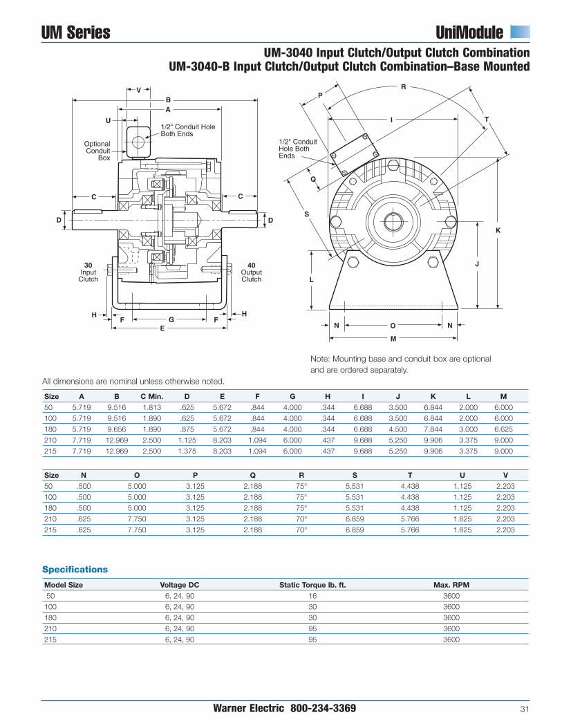
UM Series UniModule
Warner Electric 800-234-3369 31
UM-3040 Input Clutch/Output Clutch CombinationUM-3040-B Input Clutch/Output Clutch Combination–Base Mounted
Size N O P Q R S T U V50 .500 5.000 3.125 2.188 75° 5.531 4.438 1.125 2.203
100 .500 5.000 3.125 2.188 75° 5.531 4.438 1.125 2.203
180 .500 5.000 3.125 2.188 75° 5.531 4.438 1.125 2.203
210 .625 7.750 3.125 2.188 70° 6.859 5.766 1.625 2.203
215 .625 7.750 3.125 2.188 70° 6.859 5.766 1.625 2.203
All dimensions are nominal unless otherwise noted.
Size A B C Min. D E F G H I J K L M50 5.719 9.516 1.813 .625 5.672 .844 4.000 .344 6.688 3.500 6.844 2.000 6.000
100 5.719 9.516 1.890 .625 5.672 .844 4.000 .344 6.688 3.500 6.844 2.000 6.000
180 5.719 9.656 1.890 .875 5.672 .844 4.000 .344 6.688 4.500 7.844 3.000 6.625
210 7.719 12.969 2.500 1.125 8.203 1.094 6.000 .437 9.688 5.250 9.906 3.375 9.000
215 7.719 12.969 2.500 1.375 8.203 1.094 6.000 .437 9.688 5.250 9.906 3.375 9.000
C
D
HF G
E
H
D
C
1/2" Conduit HoleBoth Ends
OptionalConduit
Box
U
AB
30Input
Clutch
V
L
N O
M
J
K
I
R
T
P
Q
S
1/2" ConduitHole BothEnds
N
40OutputClutch
F
Note: Mounting base and conduit box are optionaland are ordered separately.
Specifications
Model Size Voltage DC Static Torque lb. ft. Max. RPM50 6, 24, 90 16 3600
100 6, 24, 90 30 3600
180 6, 24, 90 30 3600
210 6, 24, 90 95 3600
215 6, 24, 90 95 3600
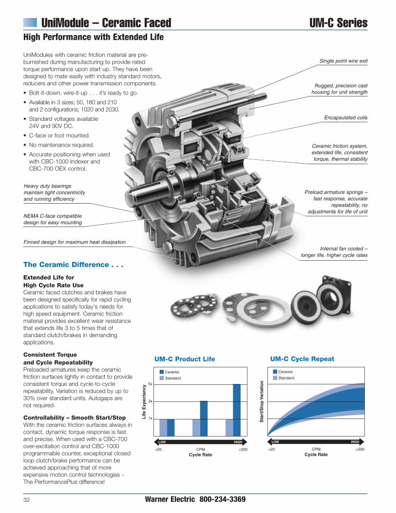
UniModule – Ceramic Faced UM-C Series
32 Warner Electric 800-234-3369
High Performance with Extended Life
UM-C Cycle Repeat Chart11/14/99page 28
Sta
rt/S
top
Var
iati
on
Cycle Rate
LOW
<20 CPM >200
Ceramic
Standard
HIGH
UM-C Product Life Chart11/14/99page 28
Ceramic
Standard
Lif
e E
xpec
tan
cy
5x
3x
1x
Cycle Rate
LOW
<20 CPM >200
HIGH
UniModules with ceramic friction material are pre-burnished during manufacturing to provide ratedtorque performance upon start up. They have beendesigned to mate easily with industry standard motors,reducers and other power transmission components.
• Bolt-it-down, wire-it-up . . . it’s ready to go.
• Available in 3 sizes; 50, 180 and 210and 2 configurations; 1020 and 2030.
• Standard voltages available 24V and 90V DC.
• C-face or foot mounted.
• No maintenance required.
• Accurate positioning when usedwith CBC-1000 Indexer andCBC-700 OEX control.
Rugged, precision casthousing for unit strength
Encapsulated coils
NEMA C-face compatible design for easy mounting
Heavy duty bearingsmaintain tight concentricityand running efficiency
Finned design for maximum heat dissipation
Preload armature springs –fast response, accurate
repeatability, noadjustments for life of unit
Single point wire exit
Ceramic friction system,extended life, consistenttorque, thermal stability
Internal fan cooled –longer life, higher cycle rates
The Ceramic Difference . . .
Extended Life for High Cycle Rate UseCeramic faced clutches and brakes havebeen designed specifically for rapid cyclingapplications to satisfy today's needs forhigh speed equipment. Ceramic frictionmaterial provides excellent wear resistancethat extends life 3 to 5 times that ofstandard clutch/brakes in demandingapplications.
Consistent Torque and Cycle RepeatabilityPreloaded armatures keep the ceramicfriction surfaces lightly in contact to provideconsistent torque and cycle-to-cyclerepeatability. Variation is reduced by up to30% over standard units. Autogaps are not required.
Controllability – Smooth Start/StopWith the ceramic friction surfaces always incontact, dynamic torque response is fastand precise. When used with a CBC-700over-excitation control and CBC-1000programmable counter, exceptional closedloop clutch/brake performance can beachieved approaching that of moreexpensive motion control technologies –The PerformancePlus difference!
UM-C Product Life UM-C Cycle Repeat
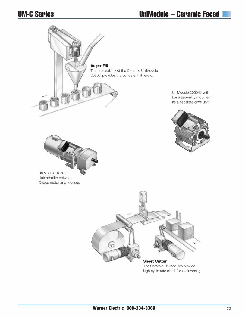
UM-C Series UniModule – Ceramic Faced
Warner Electric 800-234-3369 33
UniModule 1020-Cclutch/brake betweenC-face motor and reducer.
Auger FillThe repeatability of the Ceramic UniModule2030C provides the consistent fill levels.
Sheet CutterThe Ceramic UniModules providehigh cycle rate clutch/brake indexing.
UniModule 2030-C withbase assembly mountedas a separate drive unit.

Ceramic UniModule clutch/brake units maybe mounted directly to NEMA C-facemotors and reducers, or can be basemounted.
1. Determine MountingConfiguration
a. NEMA C-face Mounting (1020Configuration)
To select the correct Ceramic UniModulepackage, determine the NEMA framesize of your motor and/or reducer, andchoose the corresponding sizeUniModule from the Frame SizeSelection chart.
b. Base Mount (2030Configuration)
Ceramic UniModule assemblies may bemounted as separate drive units drivenfrom the prime mover by V-belts, chainand sprockets, couplings, timing beltsand other standard power transmissioncomponents.
Select the correct size module from theHorsepower vs. Shaft Speed chart bydetermining the motor horsepower andRPM at the module location. Thecorrect size UniModule is shown at theintersection of the HP and operatingspeed. For additional sizing information,refer to the technical sizing procedure(step 2).
UniModule – Ceramic Faced UM-C Series
34 Warner Electric 800-234-3369
Selection
Frame Size Selection
NEMA Frame Size UniModule Size56C/48Y UM-50-C182C/143TC UM-180-C184C/145TC213C/182TC UM-210-C215C/184TC
2. Determine Technical Requirements
Technical considerations for sizing andselection are torque and heatdissipation. Each merits carefulconsideration, especially heatdissipation as over time, use inexcessive temperature environments willhave an adverse effect on bearing lifeand coil wire insulation integrity.
Compare the calculated torquerequirement with the average dynamictorque ratings. Select a unit withadequate torque. If the unit selected ontorque is different than the unit selectedbased on heat, select the larger sizeunit.
Horsepower vs. Shaft Speed
UM-C HP/Shaft Speed Chart11/16/99page 30
1/4
1/2
3/4
1
1-1/2
2
3
5
7-1/2
HP SHAFT SPEED AT CLUTCH (IN RPM)
Horsepower vs. Shaft Speed
100 200 300 400 500 600 700 800 900 1000 1100 1200 1500 1800 2000 2400 3000 3600
10
UM-50-C
UM-180-C
UM-210-C
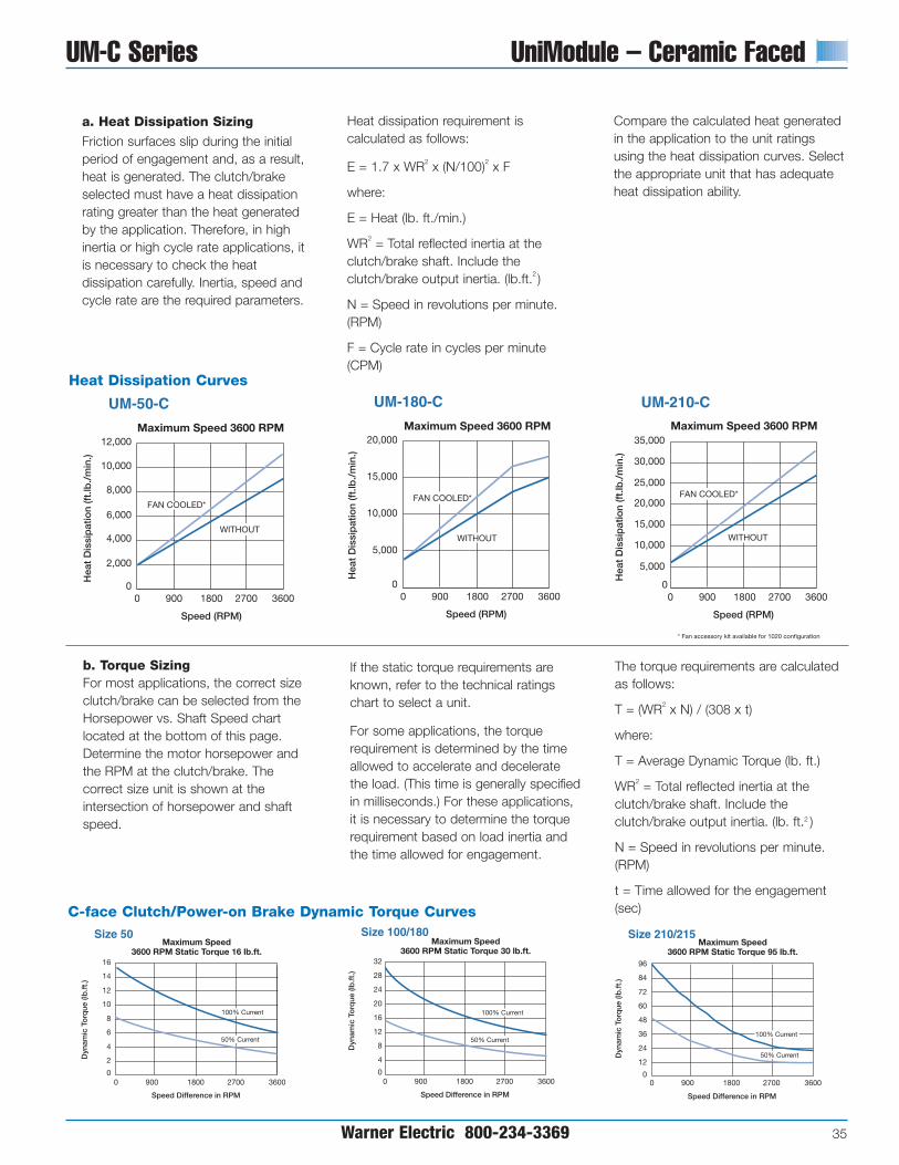
UM-C Series UniModule – Ceramic Faced
Warner Electric 800-234-3369 35
a. Heat Dissipation Sizing
Friction surfaces slip during the initialperiod of engagement and, as a result,heat is generated. The clutch/brakeselected must have a heat dissipationrating greater than the heat generatedby the application. Therefore, in highinertia or high cycle rate applications, itis necessary to check the heatdissipation carefully. Inertia, speed andcycle rate are the required parameters.
Heat dissipation requirement iscalculated as follows:
E = 1.7 x WR2 x (N/100)2 x F
where:
E = Heat (lb. ft./min.)
WR2 = Total reflected inertia at theclutch/brake shaft. Include theclutch/brake output inertia. (lb.ft.2 )
N = Speed in revolutions per minute.(RPM)
F = Cycle rate in cycles per minute(CPM)
Compare the calculated heat generatedin the application to the unit ratingsusing the heat dissipation curves. Selectthe appropriate unit that has adequateheat dissipation ability.
b. Torque SizingFor most applications, the correct sizeclutch/brake can be selected from theHorsepower vs. Shaft Speed chartlocated at the bottom of this page.Determine the motor horsepower andthe RPM at the clutch/brake. Thecorrect size unit is shown at theintersection of horsepower and shaftspeed.
If the static torque requirements areknown, refer to the technical ratingschart to select a unit.
For some applications, the torquerequirement is determined by the timeallowed to accelerate and deceleratethe load. (This time is generally specifiedin milliseconds.) For these applications,it is necessary to determine the torquerequirement based on load inertia andthe time allowed for engagement.
The torque requirements are calculatedas follows:
T = (WR2 x N) / (308 x t)
where:
T = Average Dynamic Torque (lb. ft.)
WR2 = Total reflected inertia at theclutch/brake shaft. Include theclutch/brake output inertia. (lb. ft.2 )
N = Speed in revolutions per minute.(RPM)
t = Time allowed for the engagement(sec)
900 1800 2700 36000
UM-210-C
Maximum Speed 3600 RPM
0
5,000
10,000
15,000
20,000
30,000
35,000
Speed (RPM)
Hea
t D
issi
pat
ion
(ft.
lb./
min
.)
FAN COOLED*
WITHOUT
900 1800 2700 36000
UM-180-C
Maximum Speed 3600 RPM
0
5,000
10,000
15,000
20,000
Speed (RPM)
Hea
t D
issi
pat
ion
(ft.
lb./
min
.)
FAN COOLED*
WITHOUT
900 1800 2700 36000
UM-50-C
Maximum Speed 3600 RPM
0
2,000
4,000
6,000
8,000
10,000
12,000
Speed (RPM)
Hea
t D
issi
pat
ion
(ft.
lb./
min
.)
FAN COOLED*
WITHOUT
25,000
* Fan accessory kit available for 1020 configuration
50% Current
16
Size 50Maximum Speed
3600 RPM Static Torque 16 lb.ft.
12
8
4
0
14
10
6
2
0 900 1800 2700 3600
100% Current
Dyn
amic
To
rque
(lb
.ft.
)
Speed Difference in RPM
32
Size 100/180Maximum Speed
3600 RPM Static Torque 30 lb.ft.
0
28
24
20
16
12
8
4
0
100% Current
50% Current
Dyn
amic
To
rque
(lb
.ft.
)
Speed Difference in RPM
900 1800 2700 3600
96
Size 210/215 Maximum Speed
3600 RPM Static Torque 95 lb.ft.
84
72
60
48
36
24
12
00
Dyn
amic
To
rque
(lb
.ft.
)
Speed Difference in RPM
900 1800 2700 3600
100% Current
50% Current
Heat Dissipation Curves
C-face Clutch/Power-on Brake Dynamic Torque Curves
50% Current
16
Size 50Maximum Speed
3600 RPM Static Torque 16 lb.ft.
12
8
4
0
14
10
6
2
0 900 1800 2700 3600
100% Current
Dyn
amic
To
rque
(lb
.ft.
)
Speed Difference in RPM
32
Size 100/180Maximum Speed
3600 RPM Static Torque 30 lb.ft.
0
28
24
20
16
12
8
4
0
100% Current
50% Current
Dyn
amic
To
rque
(lb
.ft.
)
Speed Difference in RPM
900 1800 2700 3600
96
Size 210/215 Maximum Speed
3600 RPM Static Torque 95 lb.ft.
84
72
60
48
36
24
12
00
Dyn
amic
To
rque
(lb
.ft.
)
Speed Difference in RPM
900 1800 2700 3600
100% Current
50% Current
50% Current
16
Size 50Maximum Speed
3600 RPM Static Torque 16 lb.ft.
12
8
4
0
14
10
6
2
0 900 1800 2700 3600
100% Current
Dyn
amic
To
rque
(lb
.ft.
)
Speed Difference in RPM
32
Size 100/180Maximum Speed
3600 RPM Static Torque 30 lb.ft.
0
28
24
20
16
12
8
4
0
100% Current
50% Current
Dyn
amic
To
rque
(lb
.ft.
)
Speed Difference in RPM
900 1800 2700 3600
96
Size 210/215 Maximum Speed
3600 RPM Static Torque 95 lb.ft.
84
72
60
48
36
24
12
00
Dyn
amic
To
rque
(lb
.ft.
)
Speed Difference in RPM
900 1800 2700 3600
100% Current
50% Current
900 1800 2700 36000
UM-210-C
Maximum Speed 3600 RPM
0
5,000
10,000
15,000
20,000
30,000
35,000
Speed (RPM)H
eat
Dis
sip
atio
n (f
t.lb
./m
in.)
FAN COOLED*
WITHOUT
900 1800 2700 36000
UM-180-C
Maximum Speed 3600 RPM
0
5,000
10,000
15,000
20,000
Speed (RPM)
Hea
t D
issi
pat
ion
(ft.
lb./
min
.)
FAN COOLED*
WITHOUT
900 1800 2700 36000
UM-50-C
Maximum Speed 3600 RPM
0
2,000
4,000
6,000
8,000
10,000
12,000
Speed (RPM)
Hea
t D
issi
pat
ion
(ft.
lb./
min
.)
FAN COOLED*
WITHOUT
25,000
* Fan accessory kit available for 1020 configuration
900 1800 2700 36000
UM-210-C
Maximum Speed 3600 RPM
0
5,000
10,000
15,000
20,000
30,000
35,000
Speed (RPM)H
eat
Dis
sip
atio
n (f
t.lb
./m
in.)
FAN COOLED*
WITHOUT
900 1800 2700 36000
UM-180-C
Maximum Speed 3600 RPM
0
5,000
10,000
15,000
20,000
Speed (RPM)
Hea
t D
issi
pat
ion
(ft.
lb./
min
.)
FAN COOLED*
WITHOUT
900 1800 2700 36000
UM-50-C
Maximum Speed 3600 RPM
0
2,000
4,000
6,000
8,000
10,000
12,000
Speed (RPM)
Hea
t D
issi
pat
ion
(ft.
lb./
min
.)
FAN COOLED*
WITHOUT
25,000
* Fan accessory kit available for 1020 configuration

UniModule – Ceramic Faced UM-C Series
36 Warner Electric 800-234-3369
Specifications
UniModule Size Shaft Dia. Static Torque lb. ft. Horsepower Max. RPM Voltage DC NEMA Frame SizeUM50-C 5/8" 16 1/4-3/4 3600 6, 24 and 90 56C/48Y
UM180-C 7/8" 30 1-2 3600 6, 24 and 90182C/143TC184C/145TC
UM210-C 1-1/8" 95 3-5 3600 6, 24 and 90213/182TC
215C/184TC
3. Select AccessoriesWarner Electric UniModules can be fittedwith several accessories to extend theircapacity and ease of mounting.
a. Conduit BoxNEMA 4 and UL listed.
b. Mounting BracketsTwo styles of mounting brackets areavailable for simplified installation. Thebase mount is used with the 2030configuration. A motor mount is alsoavailable and provides sturdy supportfor the 1020 and a motor.
c. Fan Kit (1020 only)Extends the thermal capacity of anysize UM. Mounts between motor andUM, includes shaft fan, guard andhardware.
4. Select ControlWarner Electric manufactures clutch/brakecontrols to meet several system functionsincluding:
• On/Off
• Torque adjust
• Overexcitation
• Position loop
Many requirements beyond function canimpact control selection. See the ControlsSection on page 141 for completeinformation.

UM-C Series UniModule – Ceramic Faced
Warner Electric 800-234-3369 37
Selection/Ordering Information
Part Numbers
Configuration Model No. Voltage Part NumberUM 50-1020-C 6 5370-273-077
24 5370-273-07890 5370-273-079
1020 UM 180-1020-C 6 5370-273-073(Motor Clutch/Brake) 24 5370-273-074
90 5370-273-075
UM 210-1020-C 6 5371-273-03524 5371-273-03690 5371-273-037
UM 50-2030-C 6 5370-273-08524 5370-273-08690 5370-273-087
2030 UM 180-2030-C 6 5370-273-081(Input Clutch/Brake) 24 5370-273-082
90 5370-273-083
UM 210-2030-C 6 5371-273-03924 5371-273-04090 5371-273-041
Accessories
Description UM-C Size Part Number
Conduit BoxAll sizes 5370-101-042
Conduit ControlCBC-150-1 (120 V) 6004-448-001CBC-150-2 (220 V) 6004-448-002
50 5370-101-055Fan Kits 1020 180 5370-101-054
210 5371-101-029
Base Mount Kits50 5370-101-004
for 1020-C180 5370-101-002210 5371-101-001
Motor Mount Kit50 5370-101-010
for 2030-C180 5370-101-012210 5371-101-012
How to Order
Motor or Reducer MountedSimply combine the size number with the configuration of the required UniModule.Specify voltage. See chart for specific part numbers. Order optional conduit box ifdesired.
Base MountedSimply combine the size number with the configuration of the required UniModule.Specify voltage. See chart for specific part numbers. Order optional conduit box ifdesired.
Example
UM-180 1020-C 90 Volt
Brake
Motor Clutch
Size
Example
UM-180 2030-B 90 Volt
Base
Input Clutch
Brake
Size

UniModule – Ceramic Faced UM-C SeriesUM-1020-C Motor Clutch/Brake Combination
38 Warner Electric 800-234-3369
All dimensions are nominal, unless otherwise noted.
Size A B C D E F G H I J K L M N
50 6.750 4.844 1.813 6.750 .625 .937 2.203 7.687 7.274 5.531 2.188 3.125 4.438 6.688
180 6.828 4.844 1.812 6.750 .875 .937 2.203 7.687 7.274 5.531 2.188 3.125 4.438 6.688
210 9.391* 6.422* 2.500 9.250 1.125 1.125* 2.203 10.187 9.297 6.859 2.188 3.125 6.766 9.688
*Dimension includes the .500 thick adapter. Required for C-face mounting to a motor.
M
L
K
J
N
F
AV
C
E
B
I
DH
H
1/2" ConduitHole BothEnds
OptionalConduitBoxOptional
Fan Kit
Specifications
UniModule Size Shaft Dia. Static Torque lb. ft. Horsepower Max. RPM Voltage DC NEMA Frame SizeUM50-C .625 16 1/4-3/4 3600 6, 24 and 90 56C/48Y
UM180-C .875 30 1-2 3600 6, 24 and 90182C/143TC184C/145TC
UM210-C 1.125 95 3-5 3600 6, 24 and 90213/182TC
215C/184TC
For NEMA Standard Frame size, see page 137.

All dimensions are nominal, unless otherwise noted.
Size A B C Min. D E F G H I J K50 5.719 9.516 1.813 .625 5.672 .844 4.000 .344 6.688 3.500 6.844
180 5.719 9.656 1.890 .875 5.672 .844 4.000 .344 6.688 4.500 7.844
210 7.719 12.969 2.500 1.125 8.203 1.094 6.000 .437 9.688 5.250 9.906
Warner Electric 800-234-3369 39
UM-C Series UniModule – Ceramic FacedUM-2030-C Brake/Input Clutch Combination
UM-2030-C-B Brake/Input Clutch Combination–Base Mounted
Size L M N O P Q R S T U V50 2.000 6.000 .500 5.000 3.125 2.188 75° 5.531 4.438 1.125 2.203
180 3.000 6.625 .500 5.000 3.125 2.188 75° 5.531 4.438 1.125 2.203
210 3.375 9.000 .625 7.750 3.125 2.188 70° 6.859 5.766 1.625 2.203
C
D
HF G
E
H
D
C
1/2" Conduit Hole Both Ends
OptionalConduit
Box
U
AB
2030 Modules with Base (B)V
F
L
N O
M
N
J
K
I
R
T
P
Q
S
1/2" Conduit HoleBoth Ends
Note: Mounting base is optional and must be ordered separately.
Specifications
UniModule Size Shaft Dia. Static Torque lb. ft. Horsepower Max. RPM Voltage DC NEMA Frame SizeUM50-C .625 16 1/4-3/4 3600 6, 24 and 90 56C/48Y
UM180-C .875 30 1-2 3600 6, 24 and 90182C/143TC184C/145TC
UM210-C 1.125 95 3-5 3600 6, 24 and 90213/182TC
215C/184TC
For NEMA standard frame sizes, see page 137.

Enclosed UniModule EUM/EUM-W Series
40 Warner Electric 800-234-3369
Contamination-Proof Design
Clean, quiet, operation. Nothing can getin, nothing can get out. Enclosed designeliminates damage to the workingcomponents. Prevents friction wearparticles from escaping.
One piece, C-face package completelyassembled and factory aligned. Mateseasily with standard motors and reducers.Foot mounted package also available.Easy-to-install and no maintenancerequired.
Bolt-it-down, wire-it-up. UniModule isready to go. Automatic adjustment forwear. Complete control capability.
Available with built-in power supply orused with separate controls for soft startsand stops . . . or for fast acting, accuratecycling.
• Factory burnished for out-of-box torque
• Superior heat transfer
• Dual endbell for easy repair
• Single point electrical connection
• Optional conduit box
• Optional integral control
Improved Hub Design/AutogapSystem• Improved for longer spline life
• Autogap functions over broadcurrent range
• New hub material
Two Versions
EUM Totally EnclosedEUM (black) units are totally enclosedto keep wear particles in and excludecontaminants and are suitable for mostindustrial applications.
EUM-W Washdown UnitEUM-W (white) units are ideal forapplications that require frequentwashing with high pressure spraysystems.
Optional CBC-150 control can bemounted in conduit box
Single pointelectrical connection
Encapsulated coils –3 coil voltages
Totally enclosed
Rugged, precisioncast housing
Patented Autogaps®
automatically adjustfor wear
Easy set screw access
NEMA C-facecompatible design

EUM/EUM-W Series Enclosed UniModule
Warner Electric 800-234-3369 41
EUM Series Clutch/Brakes and Clutch Combinations
EUM-W Series Clutch/BrakesWashdown Unit
Totally Enclosed VersionThe Enclosed UniModule (EUM)packages the hardworking componentsfrom EM and UM products into a totallyenclosed housing. This rugged housingkeeps wear particles in and contaminantsout and provides quiet operation. Pre-assembled and pre-aligned at the factory,and pre-burnished for rated torquedirectly out-of-box.
EUM (black) units are totally enclosed.They are suitable for most industrialapplications and tolerate infrequent, lightwashing. They have aluminum endbellsand a finned housing for rapid heatdissipation.
The washdown version of the EUM usesstainless steel shafting, USDA approvedcoating, corrosion resistant fasteners andspecial sealing accessories for use inwashdown applications.
EUM-W (white) units are ideal forapplications that require frequent washingwith high pressure spray systems. Theirsmooth exterior does not allow foodparticles, or other contaminants, to gettrapped and become host tobacteriological growth.
• Keeps contaminants out
• Keeps wear particles in
• Quiet operation
• Finned for heat dissipation
• UL listed when optional conduit boxis installed
• USDA approved coating
• Stainless steel shafting
• Sealing (gaskets and plugs)
• Smooth exterior – easy washdown
• Corrosion resistant hardware
• Sealed/shielded bearings
• Baffled ventilation system
• Designed for IP65 enclosurerequirements
• UL listed when conduit box isemployed
• BISSC Certified

Enclosed UniModule EUM/EUM-W Series
42 Warner Electric 800-234-3369
Applications and Mounting Configurations
Enclosed UniModule 2030 assembly basemounted for separate drive mounting.
Enclosed UniModule 1040 clutchunit mounted between a C-facemotor and reducer.
Sheet CutterThe EUM UniModules 1020 provide quiet,clean, high cycle rate clutch/brake indexing.
Food HandlingThe EUM-W UniModule 1020 has an USDAapproved coating which provides cleanlinessand safe use in food processing operations.
Auger FillerThe totally enclosed design of the EUM UniModule2030 keeps wear particles in and contaminants out.
Stacking OperationThe clean design and corrosion resistance of EUM-WUniModules 1020 make them ideal for washdownapplications.

b. Base Mounting (2030 Configuration)
Enclosed UniModule assemblies may bemounted as separate drive units drivenfrom the prime mover by V-belts, chainand sprockets, couplings, timing beltsand other standard power transmissioncomponents.
Select the correct size 2030 packagefrom the Horsepower vs. Shaft Speedchart by determining the motorhorsepower and RPM at the modulelocation. The correct size EUM is shownat the intersection of the HP andoperating speed. For additional sizinginformation, refer to the technical sizingprocedure (step 2).
EUM/EUM-W Series Enclosed UniModuleSelection
Warner Electric 800-234-3369 43
EUM/EUM-W - SelectionProcedureWarner Electric EUM clutch/brakemodules normally mount in either of twomethods: NEMA C-face mounting or basemounting.
a. NEMA C-face Mounting(1020 and 1040 Configurations)
Based on the NEMA C-face frame sizeof the prime mover, select thecorresponding clutch/brake packagesize from the Frame Size Selectionchart. Size 100 houses the componentsof the size 180 in a size 50 frame, whilesize 215 incorporates size 210components.
Select either a 1020 or a 1040 (EUMonly) configuration. The 1020 is aclutch/brake, while the 1040 is a clutchonly. The 2030 configuration is aclutch/brake for base mounting.
Horsepower vs. Shaft Speed
1. Select Configuration
EUM HP/SS Chart
SHAFT SPEED AT CLUTCH (IN RPM)100 200 300 400 500 600 700 800 900 1000 1100 1200 1500 1800 2000 2400 3000 3600
1/4
1/2
3/4
1
1-1/2
2
3
5
7-1/2
10
HP
EUM-50
EUM-100/180
EUM-210/215
Frame Size Selection
NEMA EUMFrame Size Size
56C/48YEUM-50*
EUM-100**
182C/143TCEUM-180184C/145TC
213C/182TCEUM-210215C/184TC
213TC/215TC EUM-215
*For 56C/48Y C-frame motors 3/4 HP andsmaller, the EUM-100 size may be usedwhere extended life is desirable.
**The EUM-100 size is recommended formotors 1 HP and larger.
2. Determine TechnicalRequirementsTechnical considerations for sizing andselection are torque and heat dissipation.Each merits careful consideration,especially heat dissipation as over time,use in excessive temperatureenvironments will have an adverse effecton bearing life and coil wire insulationintegrity.
Compare the calculated torquerequirement with the average dynamictorque ratings. Select a unit with adequatetorque. If the unit selected on torque isdifferent than the unit selected based onheat, select the larger size unit.
Two heat dissipation curves are shown. Afan kit accessory is available for use withthese units.

Enclosed UniModule EUM/EUM-W Series
44 Warner Electric 800-234-3369
a. Heat Dissipation Sizing
Friction surfaces slip during the initialperiod of engagement and, as a result,heat is generated. The clutch/brakeselected must have a heat dissipationrating greater than the heat generatedby the application. Therefore, in highinertia or high cycle rate applications, itis necessary to check the heatdissipation carefully. Inertia, speed andcycle rate are the required parameters.
Heat dissipation requirement iscalculated as follows:
E = 1.7 x WR2 x (N/100)2 x F
where:
E = Heat (lb. ft./min.)
WR2 = Total reflected inertia at theclutch/brake shaft. Include theclutch/brake output inertia. (lb.ft.2 )
N = Speed in revolutions per minute.(RPM)
F = Cycle rate in cycles per minute(CPM)
Compare the calculated heat generatedin the application to the unit ratingsusing the heat dissipation curves. Selectthe appropriate unit that has adequateheat dissipation ability.
b. Torque Sizing
For most applications, the correct sizeclutch/brake can be selected from theHorsepower vs. Shaft Speed chart(located at the bottom of this page).Determine the motor horsepower andthe RPM at the clutch/brake. Thecorrect size unit is shown at theintersection of horsepower and shaftspeed.
If the static torque requirements areknown, refer to the technical ratingschart to select a unit.
For some applications, the torquerequirement is determined by the timeallowed to accelerate and deceleratethe load. (This time is generally specifiedin milliseconds.) For these applications,it is necessary to determine the torquerequirement based on load inertia andthe time allowed for engagement.
The torque requirements are calculatedas follows:
T = (WR2 x N) / (308 x t)
where:
T = Average Dynamic Torque (lb. ft.)
WR2 = Total reflected inertia at theclutch/brake shaft. Include theclutch/brake output inertia. (lb. ft.2 )
N = Speed in revolutions per minute.(RPM)
t = Time allowed for the engagement(sec)
10000
EUM 50
8000
4000
6000
2000
0900 1800 2700 3600
Fan Cooled
Standard
Hea
t D
issi
pat
ion
(lb.f
t./m
in.)
Speed (RPM)
10000
EUM 100/180
8000
4000
6000
2000
0900 1800 2700 3600
Fan Cooled
Standard
Hea
t D
issi
pat
ion
(lb.f
t./m
in.)
Speed (RPM)
20000
EUM 210/215 (fan not available for 215)
16000
8000
12000
4000
0900 1800 2700 3600
Fan Cooled
Standard
Hea
t D
issi
pat
ion
(lb.f
t./m
in.)Speed (RPM)
16 32
EUM 50 EUM 100/180
96
EUM 210/215 Maximum Speed 3600 RPM
Static Torque 16 lb.ft.Maximum Speed 3600 RPM
Static Torque 30 lb.ft.Maximum Speed 3600 RPM
Static Torque 95 lb.ft.
Speed Difference in Hundreds of RPMSpeed Difference in Hundreds of RPM Speed Difference in Hundreds of RPM
0 8 16 24 32 40
12
8
4
0
28
24
20
16
12
8
4
0
84
72
60
48
36
24
12
00 8 16 24 32 400 8 16 24 32 40
100% Current
50% Current
100% Current
50% Current
100% Current
Dyn
amic
To
rque
(lb
.ft.
)
Dyn
amic
To
rque
(lb
.ft.
)
Dyn
amic
To
rque
(lb
.ft.
)
50% Current
Enclosed UniModule Heat Dissipation Curves
C-face Clutch/Power-on Brake Dynamic Torque Curves
10000
EUM 50
8000
4000
6000
2000
0900 1800 2700 3600
Fan Cooled
Standard
Hea
t D
issi
pat
ion
(lb.f
t./m
in.)
Speed (RPM)
10000
EUM 100/180
8000
4000
6000
2000
0900 1800 2700 3600
Fan Cooled
Standard
Hea
t D
issi
pat
ion
(lb.f
t./m
in.)
Speed (RPM)
20000
EUM 210/215 (fan not available for 215)
16000
8000
12000
4000
0900 1800 2700 3600
Fan Cooled
Standard
Hea
t D
issi
pat
ion
(lb.f
t./m
in.)
Speed (RPM)
10000
EUM 50
8000
4000
6000
2000
0900 1800 2700 3600
Fan Cooled
Standard
Hea
t D
issi
pat
ion
(lb.f
t./m
in.)
Speed (RPM)
10000
EUM 100/180
8000
4000
6000
2000
0900 1800 2700 3600
Fan Cooled
Standard
Hea
t D
issi
pat
ion
(lb.f
t./m
in.)
Speed (RPM)
20000
EUM 210/215 (fan not available for 215)
16000
8000
12000
4000
0900 1800 2700 3600
Fan Cooled
Standard
Hea
t D
issi
pat
ion
(lb.f
t./m
in.)
Speed (RPM)
16 32
EUM 50 EUM 100/180
96
EUM 210/215 Maximum Speed 3600 RPM
Static Torque 16 lb.ft.Maximum Speed 3600 RPM
Static Torque 30 lb.ft.Maximum Speed 3600 RPM
Static Torque 95 lb.ft.
Speed Difference in Hundreds of RPMSpeed Difference in Hundreds of RPM Speed Difference in Hundreds of RPM
0 8 16 24 32 40
12
8
4
0
28
24
20
16
12
8
4
0
84
72
60
48
36
24
12
00 8 16 24 32 400 8 16 24 32 40
100% Current
50% Current
100% Current
50% Current
100% Current
Dyn
amic
To
rque
(lb
.ft.
)
Dyn
amic
To
rque
(lb
.ft.
)
Dyn
amic
To
rque
(lb
.ft.
)
50% Current

EUM/EUM-W Series Enclosed UniModule
Warner Electric 800-234-3369 45
Specifications
UniModule ShaftHorsepower
Static Torque Cycles per Min. Max. Voltage NEMA Size Dia. lb. ft. @1750 RPM RPM DC Frame SizeEUM50 .625 1/4-3/4 16 125 3600 6, 24 or 90 56C/48Y
EUM100 1 30 90 3600 6, 24 or 90
EUM180 .625 1-2 30 90 3600 6, 24 or 90182C/143TC184C/145TC
EUM210 1.125 3-5 95 37 3600 6, 24 or 90213/182TC
215C/184TC
EUM215 1.375 7-1/2-10 95 37 3600 6, 24 or 90 213TC/215TC
3. Select Options
Warner Electric Enclosed UniModules canbe fitted with several accessories toextend their capacity and ease ofmounting.
a. Conduit BoxNEMA 4 and UL listed, available instandard and washdown versions.
b. Integral ControlThe CBC-150 dual channel control fitsinto the cover of the conduit box. It issuitable for AC side switching (triac orrelay) and includes high performancesuppression.
c. Fan Kit (1020 only)Extends the thermal capacity of anEUM. Mounts between motor andEUM, includes shaft, fan, guard andhardware. Available in standard blackcoating or food grade approved whitecoating.
d. Mounting BracketsTwo styles of mounting brackets areavailable for simplified installation. Thebase mount is used with the 2030configuration. A motor mount is alsoavailable and provides sturdy supportfor a 1020 or 1040 combination withmotor.
4. Select Control
Warner Electric manufactures clutch/brakecontrols to meet several system functionsincluding:
• On/Off
• Torque adjust
• Over excitation
• Position loop
Many requirements beyond function canimpact control selection. See the ControlsSection on page 141 for completeinformation.
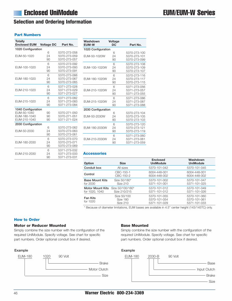
Enclosed UniModule EUM/EUM-W SeriesSelection and Ordering Information
46 Warner Electric 800-234-3369
Washdown VoltageEUM-W DC Part No.1020 Configuration
6 5370-273-100EUM-50-1020W 24 5370-273-101
90 5370-273-099
6 5370-273-108EUM-100-1020W 24 5370-273-109
90 5370-273-107
6 5370-273-116EUM-180-1020W 24 5370-273-117
90 5370-273-115
6 5371-273-056EUM-210-1020W 24 5371-273-057
90 5371-273-055
6 5371-273-086EUM-215-1020W 24 5371-273-087
90 5371-273-088
2030 Configuration6 5370-273-104
EUM-50-2030W 24 5370-273-10590 5370-273-103
6 5370-273-120EUM-180-2030W 24 5370-273-121
90 5370-273-119
6 5371-273-060EUM-210-2030W 24 5371-273-061
90 5371-273-059
Accessories
Enclosed WashdownOption Size UniModule UniModuleConduit box All sizes 5370-101-042 5370-101-045
ControlCBC-150-1 6004-448-001 6004-448-001CBC-150-2 6004-448-002 6004-448-002
Base Mount Kits Size 50/180* 5370-101-002 5370-101-047for 2030 Size 210 5371-101-001 5371-101-025
Motor Mount Kits Size 50/100/180* 5370-101-012 5370-101-049for 1020, 1040 Size 210/215 5371-101-012 5371-101-026
Fan KitsSize 50/100 5370-101-055 5370-101-060
for 1020Size 180 5370-101-054 5370-101-061Size 210 5371-101-029 5371-101-033
* Because of diameter limitations, EUM bases are available in 4.5” center height (143/145TC) only.
How to Order
Motor or Reducer MountedSimply combine the size number with the configuration of therequired UniModule. Specify voltage. See chart for specificpart numbers. Order optional conduit box if desired.
Base MountedSimply combine the size number with the configuration of therequired UniModule. Specify voltage. See chart for specificpart numbers. Order optional conduit box if desired.
Example
EUM-180 1020 90 Volt
Brake
Motor Clutch
Size
Example
EUM-180 2030-B 90 Volt
Base
Input Clutch
Brake
Size
Part Numbers
TotallyEnclosed EUM Voltage DC Part No.1020 Configuration
6 5370-273-058EUM-50-1020 24 5370-273-059
90 5370-273-057
6 5370-273-092EUM-100-1020 24 5370-273-093
90 5370-273-091
6 5370-273-066EUM-180-1020 24 5370-273-067
90 5370-273-065
6 5371-273-028EUM-210-1020 24 5371-273-029
90 5371-273-027
6 5371-273-082EUM-215-1020 24 5371-273-083
90 5371-273-084
1040 ConfigurationEUM-50-1040 90 5370-271-050EUM-180-1040 90 5370-271-051EUM-210-1040 90 5371-271-024
2030 Configuration6 5370-273-062
EUM-50-2030 24 5370-273-06390 5370-273-061
6 5370-273-070EUM-180-2030 24 5370-273-071
90 5370-273-069
6 5371-273-032EUM-210-2030 24 5371-273-033
90 5371-273-031

EUM/EUM-W Series Enclosed UniModuleEUM-1020 Clutch/Brake Combination
EUM-W-1020 Clutch/Brake Combination
Warner Electric 800-234-3369 47
Specifications
CPMUniModule Size Shaft Dia. Horsepower Static Torque lb. ft. @1750 RPM Max. RPM Voltage DC NEMA Frame SizeEUM50 .625 1/4-3/4 16 125 3600 6, 24 or 90 56C/48Y
EUM100 .625 1 30 90 3600 6, 24 or 90 56C/48Y
EUM180 .875 1-2 30 90 3600 6, 24 or 90182C/143TC184C/145TC
EUM210 1.125 3-5 95 37 3600 6, 24 or 90213/182TC
215C/184TC
EUM215 1.375 7-1/2 95 37 3600 6, 24 or 90 213TC/215TC
All dimensions are nominal, unless otherwise noted.
ESize A B C D EUM EUM-W F G H I50/100 6.750 4.844 1.813 .625 7.270 6.915 2.427 5.936 7.687 2.430
180 6.828 4.844 1.890 .875 7.270 6.915 2.427 5.936 7.687 2.430
210 8.891 5.922 2.500 1.125 10.000 10.00 3.053 7.146 10.187 3.375
215 9.391 5.922 3.000 1.375 10.000 10.00 3.053 7.146 10.187 3.375
For NEMA standard frame sizes, see page 137.
Note: Washdown Unimodules (EUM-W) do not have a finned housing.
AIF
2.203
OptionalFan Kit
OptionalConduit
Box
H
B10
Motor Clutch20
Brake
CMin.
D
G
2.188
3.125
E

Enclosed UniModule EUM/EUM-W SeriesEUM-1040 Clutch Combination
48 Warner Electric 800-234-3369
Specifications
CPMUniModule Size Shaft Dia. Horsepower Static Torque lb. ft. @1750 RPM Max. RPM Voltage DC NEMA Frame SizeEUM50 .625 1/4-3/4 16 125 3600 6, 24 or 90 56C/48Y
EUM100 .625 1 30 175 3600 6, 24 or 90 56C/48Y
EUM180 .875 1-2 30 175 3600 6, 24 or 90182C/143TC184C/145TC
EUM210 1.125 3-5 95 32 3600 6, 24 or 90213/182TC
215C/184TC
I A
2.203F
H
B
D
Cmin
OptionalConduit BoxOptional
Fan Kit 2.188
3.125
G
E
10MotorClutch
40OutputClutch
Note: Not available in Washdown version.
All dimensions are nominal, unless otherwise noted.
Size A B C D E F G H I50/100 6.750 4.844 1.813 .625 7.270 2.427 5.936 7.687 2.430
180 6.828 4.844 1.890 .875 7.270 2.427 5.936 7.687 2.430
210 8.891 5.922 2.500 1.125 10.000 3.053 7.146 10.187 3.375
For NEMA standard frame sizes, see page 137.

Specifications
CPMUniModule Size Shaft Dia. Horsepower Static Torque lb. ft. @1750 RPM Max. RPM Voltage DC NEMA Frame SizeEUM50 5/8" 1/4-3/4 16 125 3600 6, 24 or 90 56C/48Y
EUM100 5/8" 1 30 175 3600 6, 24 or 90 56C/48Y
EUM180 7/8" 1-2 30 175 3600 6, 24 or 90182C/143TC184C/145TC
EUM210 1-1/8" 3-5 95 32 3600 6, 24 or 90213/182TC
215C/184TC
EUM/EUM-W Series Enclosed UniModuleEUM-2030 Clutch/Brake
Combination–Base MountedEUM-W-2030 Clutch/Brake
Combination–Base Mounted
Warner Electric 800-234-3369 49
Note: Washdown Unimodules (EUM-W) do not have a finned housing.
OptionalConduit
Box
30Input Clutch
20Brake
2.203
2.188
3.125
OptionalBase Mount
AF
CMin.
D
B
D
CMin.
G
H
I
E
Note: Washdown UniModules (EUM-W) do not have a finned housing.
All dimensions are nominal, unless otherwise noted.
ESize A B C D EUM EUM-W F G H I50 9.516 5.672 1.813 .625 7.270 6.915 3.164 5.936 3.670 7.119
180 9.516 5.672 1.890 .875 7.270 6.915 3.164 5.936 4.484 8.119
210 12.969 8.260 2.500 1.125 10.000 10.00 4.514 7.146 5.234 10.234
For NEMA standard frame sizes, see page 137.

Module Options
50 Warner Electric 800-234-3369
For use with 2030 and 3040 units.
Size A B C D E F G Part No.50/100 6.000 5.000 5.672 4.000 3.500 .750 X .406 2.000 5370-101-004
180 6.625 5.000 5.672 4.000 4.500 .750 X .406 3.000 5370-101-002/5370-101-049
210/215 9.000 7.750 8.203 6.000 5.250 .750 X .531 3.385 5371-101-001/5371-101-026
Conduit Box
NEMA 4 and UL listed, available instandard and washdown versions.
For use with 1020, 1040, 20, 20 FBB and 1020 FBC Combinations.
Size A B C D E F Part No.50/100 9.25 8.25 11.00 8.000 3.50 .797 x .406 5370-101-010
180 9.25 8.25 11.00 8.000 4.50 .797 x .406 5370-101-012/5370-101-047
210/215 11.50 10.50 12.00 9.000 5.25 .750 x .406 5371-101-012/5371-101-025
(Optional)Motor Mount (M)
A
E
DC
B
F (4) slots
Base (B)
B
D CA
G
F (4) Slots
E
Mounting Brackets
Two styles of mounting brackets are available forsimplified installation. The base mount is used withthe 2030 configuration. A motor mount is alsoavailable and provides sturdy support for a 1020or 1040 combination with motor.
Warner Electric Enclosed UniModules can befitted with several accessories to extend theircapacity and ease of mounting.
Fan Kit (UM and EUM 1020 only)
Extends the thermal capacity of an EUM.Mounts between motor and EUM,includes shaft, fan, guard and hardware.Available in standard black coating or foodgrade approved white coating.
Integral Control
The CBC-150 dual channel control fitsinto the cover of the conduit box. It issuitable for AC side switching (triac orrelay) and includes high performancesuppression.

EC/EB Series Electro Clutches and Brakes
Warner Electric 800-234-3369 51
Shaft Mounted Clutches and Brakes
Shaft Mounted ClutchesEC SeriesAll the features of an electric clutch in aconvenient, preassembled package.Mounts on any through shaft or doubleshafted motor. Easy-to-assemble withstandard sheaves, pulleys, gears andsprockets.
Available in a wide range of bore sizes.Shaft extension makes pulley or sprocketinstallation easy.
Shaft Mounted BrakesEB SeriesElectro Brakes mount directly on a motoror through shaft for basic brakingfunctions.
Torque arm feature makes Electro Brakeseasy to install on any through shaft ordouble shaft motor.
Segmented and fluted armature discprovides maximum cooling of frictionsurfaces.
• Six sizes of clutches and brakes
• 16 lb. ft. to 465 lb. ft. torque range
• Preassembled. Factory aligned.
• Mounting flexibility
• Simple to install
Brushless DesignWarner Electric designed electromagneticcircuit eliminates brushes.
Heat DissipationSpecially designed segmented armaturedisc is segmented and fluted to providemaximum cooling of friction surfaces.Automatically adjusts for wear.
Motor mounted Electro Clutch used incombination with an Electro Brake on athrough shaft installation.
Electro Clutch/Segmented11/5/99page 74
Electro Clutch/Brushless

Electro Clutch EC SeriesShaft Mounted Clutches
52 Warner Electric 800-234-3369
Mounting flexibilityStandard Electro Clutchesare offered in a widevariety of bore sizes.
Packaged PerformanceThe engineering is built-in. Warner ElectricPackaged Performance products arefactory aligned and pre-assembled. Theyhave been designed to mate easily withindustry standard motors, reducers andother power transmission components.“Bolt-it-down and wire-it-up”. . . they’reready to go.
• Hubs mate to standard sheaves,sprockets, gears and pulleys
• Wide torque range from 16 to 465 lb. ft.
• Handle 1 to 20 HP at 1800 RPM
Simple installationEasy-to-install a pulley, sprocket,sheave or gear on the ElectroClutch shaft extension.
UL and CSA listedConduit box meets industry standards.
Typical Applications
Long life – no maintenanceSpecially designed armature discis segmented and fluted to providemaximum cooling of friction surfaces.Automatically adjusts to wear.
Reversing with Electro Clutches.
Electro Clutches used for speedchanging in a two speed drive.
No brushes to wear outWarner Electric designed eletcro-magnetic circuit eliminates brushes.

EC Series Electro ClutchSelection/Ordering Information
Warner Electric 800-234-3369 53
Selection Procedure
1. Determine the motor horsepower andr.p.m. at the clutch location.
2. Use the Horsepower vs. Shaft Speedchart to determine the right size ElectroClutch.
3. When ordering, specify bore size andvoltage.
4. To get maximum performance from yourElectro Clutch, use a Warner ElectricControl. See the Controls Section.
Note:Electro Clutches require extended lengthmotor shafts for motor mounting.
EC HP/Shaft Speed Chart
100
1/50
1/20
1/12
1/8
1/6
1/4
1/2
3/4
1
1-1/2
2
3
5
7-1/2
10
15
20
HP
Horsepower vs. Shaft Speed
SHAFT SPEED AT CLUTCH (IN RPM)1000
EC-375
EC-475
EC-650
EC-825
EC-1000
EC-1225
200 300 400 500 600 700 800 900 1100 1200 1500 1800 2000 2400 3000 3600 4000 4500 5000
Horsepower vs. Shaft Speed
Part Numbers
Model Bore VoltageSize Size DC Part No.
6 5180-271-0061/2" 24 5180-271-004
EC-37590 5180-271-0096 5180-271-002
5/8" 24 5180-271-00890 5180-271-005
6 5181-271-0045/8" 24 5181-271-008
90 5181-271-0076 5181-271-003
EC-475 3/4" 24 5181-271-00990 5181-271-0056 5181-271-002
7/8" 24 5181-271-01090 5181-271-006
6 5281-271-0041" 24 5281-271-018
90 5281-271-0076 5281-271-002
1-1/8" 24 5281-271-019
EC-65090 5281-271-0056 5281-271-009
1-1/4" 24 5281-271-02090 5281-271-0086 5281-271-003
1-3/8" 24 5281-271-01690 5281-271-006
6 5282-271-0021-1/8" 24 5282-271-008
90 5282-271-0116 5282-271-003
EC-825 1-1/4" 24 5282-271-00990 5282-271-0126 5282-271-004
1-3/8" 24 5282-271-01090 5282-271-013
6 5283-271-0021-3/8" 24 5283-271-010
90 5283-271-003
EC-1000 1-1/2"24 5283-271-01290 5283-271-0136 5283-271-004
1-5/8" 24 5283-271-01190 5283-271-005
6 5284-271-0081-5/8" 24 5284-271-013
90 5284-271-0106 5284-271-002
EC-1225 1-7/8" 24 5284-271-01490 5284-271-0036 5284-271-004
2-1/8" 24 5284-271-01590 5284-271-005
Note: Metric bores available in some sizes,consult factory.
Specifications
Electro Clutch Size Static Torque lb. ft. Max. RPM Voltage DC Total Wt. lbs.EC-375 16 5000 6, 24 or 90 4
EC-475 30 4500 6, 24 or 90 8
EC-650 95 3600 6, 24 or 90 18
EC-825 125 3600 6, 24 or 90 28
EC-1000 240 2000 6, 24 or 90 41
EC-1225 465 2000 6, 24 or 90 85

Electro Clutch EC SeriesEC-375, EC-475, EC-650
54 Warner Electric 800-234-3369
ON
M
L
CBA
S
R
PQ
D
E
FJ
GK
T IH
AA
CCBB
DD
Z
Y
X
RemovablePlug in Ends for
0.5" Conduit
U
V
FF BB
W
CC
EE
EE
EE
GG
HH
II
For Bore and KeywaySizes See Chart Below
Size N Max. O Max. P Q Max. R Min. S T U V Max. W X
375 2.484 4.984 .438 .609 3.000 1/4-20 UNC-2A 5/16 x 3/32 3.750 4.438 2.438 .313
475 3.219 6.266 .422 .658 3.641 1/4-20 UNC-2A 3/8 x 3/32 3.750 4.984 2.984 .313
650 3.547 7.141 .422 .722 4.359 1/4-20 UNC-2A 5/8 x 3/32 3.750 5.750 3.750 .313
Bore Sizes and KeywaysSize Bore Dia. Keyway
375.625 *3/16 x 1/16.500 1/8 x 1/16
.750 3/16 x 3/32475 .875 *3/16 x 1/16
.625 3/16 x 3/32
1.125 *1/4 x 1/8
6501.375 *5/16 x 3/321.000 1/4 x 1/81.250 1/4 x 1/8
*Key Furnished
Size Y Z AA BB CC DD EE Dia. FF GG HH Dia. II
375 .563 .750 5.000 .250 .500 .750 .563 .313 1.000.270
.828.260
475 .578 .750 5.000 .250 .500 .750 .563 .313 1.000.270
.828.260
650 .563 .750 10.000 .250 .500 5.750 .563 .313 1.000.270
.828.260
All dimensions are nominal, unless otherwise noted.
Size A Max. B Dia. C Min. D Dia. E Dia. F G H I J K Max. L M
375 4.078 3.125 .7505 1.3131.375
3.34410-24 UNC
.188 .375 .344 2.047 .781 1.5471.374 -3A x 5/15
475 5.172 4.000 1.0625 1.5631.625
3.9221/4-20 UNC
.281 .375 .578 2.359 .875 1.5471.624 -3A x 7/16
650 6.578 5.125 1.625 2.3752.5000
4.6251/4-20 UNC .
281 .188 .563 3.047 .953 1.5472.4985 -3A x 1/2
Specifications
Average Wt.–lbs. Inertia–WR2 (lb.ft.2 )Size Arm. & Carrier. Rotor Outer Sleeve Inner Sleeve Arm. & Carrier Rotor Outer Sleeve Inner SleeveEC-375 .60 .55 .49 .60 .010 .018 .001 .001EC-475 1.13 1.12 .78 1.22 .072 .033 .006 .002EC-650 2.3 2.5 1.6 2.37 .106 .202 .010 .013

EC Series Electro ClutchEC-825
Warner Electric 800-234-3369 55
Specifications
Inertia–WR2 (lb. ft2) Average Weight–lbs.Armature, Hub Rotor & Armature, Hub Rotor &
Model Size Voltage DC & Inner Sleeve Outer Sleeve Total Weight lbs. & Inner Sleeve Outer Sleeve6 .35 .87 28 6.0 18.5
EC-825 24 .35 .87 28 6.0 18.590 .35 .87 28 6.0 18.5
N
B
D
C
A
R
K
L
G I
H
J
E F
QPO
S
TRemovable plug inends for 1/2" conduit
X
W
V
U
Z AA
CC
DD
Y
45°
For Bore & Keyway Sizessee chart below
MMOO
LL
DDHH
KKJJ
BB
FF
GGEE
II
M
All dimensions are nominal, unless otherwise noted.Size A Max. B Dia. C D Min. E Dia. F Dia. G H I J
825 8.656 5.656 4.625 1.437 2.3752.5000
.2811/4-20 UNC
.188 .5632.4985 -3A x 3/8
Size K Max. L M N Max. O P Q Max. R* S T
825 3.047 5.219 1.547 8.000 5/16-18 UNC-2A 1.547 4.468 5/8 x 3/32 6.813 3.750
Bore Sizes and Keyways
Size Bore Dia. Keyway1.125 1/4 x 1/8
825 1.250 1/4 x 1/81.375 5/16 x 3/32
Size U V W X Y Z AA BB CC DD Dia.
825 5.063 .875 — .375 .750 16.625 17 .750 .375.330.321
Size EE FF GG Dia. HH II JJ KK LL MM NN OO
825 .438 .875 .313 .250 1.000 1.750 2.000 1.500 .750 .250.270.260
* Key supplied

Electro Clutch EC SeriesEC-1000, EC-1225
56 Warner Electric 800-234-3369
Specifications
Static Inertia–WR2 (lb. ft2) TotalModel Size Voltage DC Torque (lb. ft.) Max. Speed RPM Arm. & Hub Rotor Outer Sleeve Inner Sleeve Weight lbs.
6 240 lb. ft. 2000 .720 .894 .129 .036 41EC-1000 24 240 lb. ft. 2000 .720 .894 .129 .036 41
90 240 lb. ft. 2000 .720 .894 .129 .036 416 465 lb. ft. 2000 1.8 2.4 .129 .061 85
EC-1225 24 465 lb. ft. 2000 1.8 2.4 .129 .061 8590 465 lb. ft. 2000 1.8 2.4 .129 .061 85
A
D
C
B
P QO
E F
RH
JG
I
K
N
LM
For Bore and KeywaySizes See Chart Below
S
T
45°
W
AAZY
DD
CC
V
U
MM
OO
LL
NN
KKJJ
II
HH
BBGG
FFEE
RemovablePlug in Ends for0.5" Conduit
X
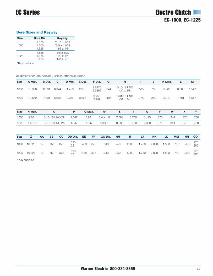
EC Series Electro ClutchEC-1000, EC-1225
EC Series Electro Clutch
Warner Electric 800-234-3369 57
All dimensions are nominal, unless otherwise noted.
Size A Max. B Dia. C D Min. E Dia. F Dia. G H I J K Max. L M
1000 10.328 6.531 6.344 1.750 2.8752.9375
.3445/16-18 UNC
.188 .750 3.969 6.000 1.5472.9365 -3A x 3/8
1225 12.672 7.531 6.969 2.234 3.6253.750 .
4065/81-16 UNC
.375 .859 5.219 7.781 1.5473.749 -3A x 3/4
Size Z AA BB CC DD Dia. EE FF GG Dia. HH II JJ KK LL MM NN OO
1000 16.625 17 .750 .375.330
.438 .875 .313 .250 1.000 1.750 2.000 1.500 .750 .250.270
.321 .260
1225 16.625 17 .750 .375.330
.438 .875 .313 .250 1.000 1.750 2.000 1.500 .750 .250.270
.321 .260
* Key supplied
Bore Sizes and Keyway
Size Bore Dia. Keyway1.375 *5/15 x 5/32
1000 1.500 *3/8 x 11/641.625 *3/8 x 1/8
1.625 *3/8 x 5/321225 1.875 *1/2 x 1/4
2.125 *1/2 x 3/16
*Key Furnished
Size N Max. O P Q Max. R* S T U V W X Y
1000 9.031 5/16-18 UNC-2A 1.547 5.281 3/4 x 1/8 7.688 3.750 6.125 .875 .344 .375 .750
1225 11.016 5/16-18 UNC-2A 1.547 7.047 7/8 x /8 8.688 3.750 7.000 .875 .344 .375 .750

Electro Brake EB SeriesShaft Mounted Brakes for Power-On Applications
58 Warner Electric 800-234-3369
An Electro Brake mounted on a throughshaft.
Selection Procedure
1. Determine the motor horsepower andr.p.m. at the brake location.
2. Use the Horsepower vs. Shaft Speedchart to determine the right size ElectroBrake.
3. When ordering, specify bore size andvoltage.
4. To get maximum performance from yourElectro Clutch, use a Warner ElectricControl. See the Controls Section.
Typical Application
Horsepower vs. Shaft Speed
EB HP/Shaft Speed Chart11/14/99page 86
1/121/81/61/41/31/23/41
1-1/2235
7-1/2101520253040506075
HP
Horsepower vs. Shaft Speed
SHAFT SPEED AT BRAKE (IN RPM)
EB-375
EB-475
EB-650EB-825
EB-1225
EB-1000
100 1000200 300 400 500 600 700 800 900 1100 1200 1500 1800 2000 2400 3000 3600 4000 4500 5000
Pre-engineered, pre-packaged brakesmount on motor or thru shafts. They havebeen designed to mate easily with industrystandard motors, reducers and otherpower transmission components. Bolt-it-down and wire-it-up . . . they’re ready to go.
• Wide torque range from 16 to 465 lb. ft.
• Handle 1 to 75 HP at 1800 RPM
• Adjustable torque arm
Mounting FlexibilityTorque arm allows mountinganywhere on shaft. Standardbushings cover a wide rangeof shaft sizes.
UL and CSA ListedConduit box meets industry standards.
Long Life,No Maintenance
Automatically adjusts forwear. Designed for
maximum heat dissipation.No lubrication necessary.
Packaged DesignNo assembly required.
Insert bushing for propershaft size, slide on shaft
and bolt down torque arm.

EB Series Electro BrakeOptions/Ordering Information
Warner Electric 800-234-3369 59
Optional Motor Shaft AdapterTen motor shaft adapters are available asan option for mounting Electro-Brakes onsingle shaft extension motors. For doubleshaft extension motors the adapter can beeliminated. A standard sheave, pulley, orsprocket, with either a tapered bushing orstraight bore, can be installed on the shaftadapter. The Electro Brake is mounted onthe end of the shaft adapter and thecomplete assembly fits onto the motorshaft and is secured with setscrews.Fitting the belts or chain and attaching thetorque arm completes the installation.
All dimensions are nominal unless otherwise noted.
DodgeKey Key Key Bushing
Model A Kwy. Part No. 1 B Kwy. Part No. 2 C Kwy. Part No. 3 Size D E F G H I
EB-375 5/83/16x
* 7/83/16x
590-0016 5/83/16x
590-0043 None4.391
2.391
21/4-20
1.1253/32 3/32 3/32 4.359 .359 UNC
EB-375 7/83/16x
* 1-1/41/4x
590-0022 5/83/16x
590-0043 None4.578
2-1/4.516
2-1/4 1.5003/32 1/8 3/32 4.742 .484
EB-475 1-1/81/4x
* 1-5/83/8x
590-0041 11/4x
**#1008 4.516
2-3/4.641
2-3/41/2-13
1.7501/8 3/16 1/8 1" 4.484 .609 UNC
EB-650 1-3/85/16x
* 21/2x
590-0042 1-3/85/16x
590-0044#1310 5.547
3-3/8.641
3-3/81/2-13
2.1255/32 1/4 5/32 1-3/8" 5.515 .609 UNC
EB-650 1-5/83/8x
* 2-1/41/2x
590-0042 1-3/85/16x
590-0044#1310 6.172
4.641
4 2.3753/16 1/4 5/32 1-3/8" 6.140 .609
EB-1000 1-5/83/8x
* 2-15/163/4x
590-0052 1-5/83/8x
**#1615 8.297
5-1/4 53/4-10
2.9373/16 7/16 7/32 1-5/8" 8.265 UNC
EB-1000 1-7/81/2x
* 2-15/163/4x
590-0052 1-5/83/8x
**#1615
2.9377/32 7/16 7/32 1-5/8"
EB-1000 2-1/81/2x
590-0062 2-15/163/4x
590-0069 1-5/83/8x
**#1615
2.9371/8 5/16 7/32 1-5/8"
EB-1225 2-1/81/2x
* 3-3/47/8x
590-0049 2-1/81/2x
590-0048#2517 10.672
7-1/4 6-7/87/8-9
3.7507/32 7/16 9/32 2-1/8" 10.640 UNC
EB-1225 2-3/85/8x
* 3-3/47/8x
590-0049 2-1/81/2x
590-0048#2517
3.7509/32 7/16 9/32 2-1/8"
* Standard Square Key Furnished with Motor.
** Special Key Furnished with Bushing.
Note: For adapter part numbers, see page 108.
Part Numbers
Model Bore VoltageSize Size DC Part No.
6 5380-170-0051/2" 24 5380-170-006
EB-37590 5380-170-0046 5380-170-003
5/8" 24 5380-170-00790 5380-170-002
6 5381-170-003EB-475 1/2" to 1" 24 5381-170-004
90 5381-170-002
6 5382-170-003EB-650 1/2" to 1-3/8" 24 5382-170-005
90 5382-170-002
Model Bore VoltageSize Size DC Part No.
6 5383-170-002EB-825 1/2" to 1-1/2" 24 5383-170-004
90 5383-170-005
6 5384-170-003EB-1000 1/2" to 1-5/8" 24 5384-170-005
90 5384-170-002
6 5385-170-003EB-1225 1/2" to 2-12" 24 5385-170-005
90 5385-170-002
Note: EB-375 also available in some metric bores.EB-475-1225 use bushings which are available in metric bores.
MotorAdapter
A
B
D
E
B C
G
A I
F
H(Threaded
Removal Hole)
2
3 1
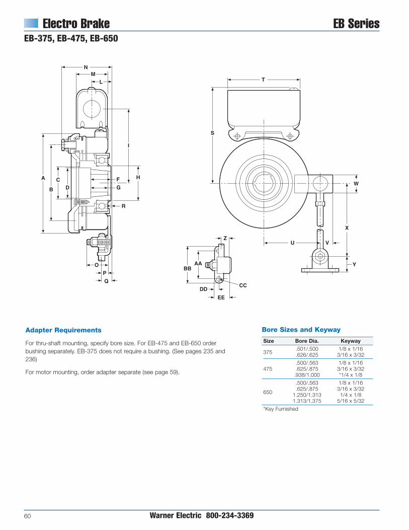
Electro Brake EB SeriesEB-375, EB-475, EB-650
60 Warner Electric 800-234-3369
Bore Sizes and Keyway
Size Bore Dia. Keyway
375.501/.500 1/8 x 1/16.626/.625 3/16 x 3/32
.500/.563 1/8 x 1/16475 .625/.875 3/16 x 3/32
.938/1.000 *1/4 x 1/8
.500/.563 1/8 x 1/16
650.625/.875 3/16 x 3/32
1.250/1.313 1/4 x 1/81.313/1.375 5/16 x 5/32
*Key Furnished
Adapter Requirements
For thru-shaft mounting, specify bore size. For EB-475 and EB-650 orderbushing separately. EB-375 does not require a bushing. (See pages 235 and236)
For motor mounting, order adapter separate (see page 59).
NM
L
I
HF
GDC
B
A
R
O
P
Q
AABB
DD
EE
Z
CC
Y
VU
X
W
S
T

EB Series Electro Brake
Warner Electric 800-234-3369 61
EB Series Electro BrakeEB-375, EB-475, EB-650
Specifications
Inertia–WR2 (lb. ft2)
Model Size Voltage DC Static Torque (lb. ft.) Max. Speed RPM Arm. & Carrier Hub Total Weight lbs.
EB-375 6, 24, 90 16 5000 .010 .001 4
EB-475 6, 24, 90 30 4500 .072 .006 7
EB-650 6, 24, 90 95 3600 .106 .010 11.3
All dimensions are nominal, unless otherwise noted.
Size A Max. B Dia. C Min. D Dia. E F G H Dia. I J K L M N Max. O
375 4.078 3.125 .7505 – .031 1.656 – 1.375 3.34410-32 UNF
.188 1.047 1.547 2.438 .844-3A x 1/4
475 5.172 4.000 1.663 1.594 – 1.000 1.000 1.781 3.875 – – .986 1.547 2.922 1.094
650 6.578 5.125 2.343 2.281 – 1.313 1.000 2.563 4.656 – – .986 1.547 3.109 1.031
Size P Q R S Max. T U V W X Y Z AA BB CC DD EE
375 .281 .625.094
4.453 3.750 2.453 .666 1.000 8.000 .635 .359 1.500 2.000.270
.250 .781Min. .260
475 .313 .531.125
4.984 3.750 3.093 .697 1.000 10.000 .635 .391 1.500 2.000.270
.250 .781Max. .260
650 .344 .641.203
5.766 3.750 4.063 .843 1.125 11.000 .635 .438 1.500 2.000.270
.250 .781Max. .260

Electro Brake EB Series
62 Warner Electric 800-234-3369
EB-825
Size A Max. B Max. C Dia. D E F G H I J Max. K L M825 8.656 4.625 2.625 .563 1.250 – 5.281 1.344 1.547 3.375 – – .344
Size N O P Max. Q R S T U V W X Y Z
825 1.031 .641 6.813 3.750 4.813 11.000 1.125 – 1.500 2.000 –.270
.781.260
Specifications
Inertia–WR2 (lb. ft2)Model Size Voltage DC Static Torque lb. ft. Max. Speed RPM Arm. & Hub Total Weight lbs.EB-825 6, 24, 90 125 3600 .459 20
RemovablePlug In Endsfor 1/2" Conduit
Q
P
R
T
S
J
I
H
G
A B C
M
O
N
ED
Z
WV
Y
R

EB Series Electro BrakeEB-1000, EB-1225
Warner Electric 800-234-3369 63
Adapter RequirementsFor thru-shaft mounting, specify bore size. Order bushing separately.
For motor mounting order adapter separate (see page 59).
Size A Max. B Max. C Dia. D E F G H I J Max. K L M1000 10.328 6.344 2.563 1.563 1.500 7.688 6.531 1.281 1.547 3.531 2.266 4.531 –
1225 12.672 6.969 3.391 .875 1.750 8.438 7.531 1.297 1.547 3.719 2.453 4.703 –
Size N O P Max. Q R S T U V W X Y Z
1000 – – 7.688 3.750 – 18.000 1.500 .750 .2375 3.375 1.438.413
–.404
1225 – – 8.688 3.750 – 18.000 1.500 .750 2.375 3.375 1.438.413
–.404
Specifications
Inertia–WR2 (lb. ft2)Model Size Voltage DC Static Torque lb. ft. Max. Speed RPM Arm. & Hub Hub Total Weight lbs.EB-1000 6, 24, 90 240 2000 .720 .129 35.5
EB-1225 6, 24, 90 465 2000 1.8 .129 52.5
RemovablePlug In Endsfor 1/2" Conduit
Q
P
R
T
S
U
V
W
YX
JI
H
G
CBA
KL
F
D
E

AT Clutches and Brakes ATC/ATB SeriesRugged, Durable, Heavy Duty Clutches and Brakes
64 Warner Electric 800-234-3369
Advanced TechnologyDesign Advantages
• Replaceable friction face
• Steel wear surface and cast ironhub/armature carrier
• Non-asbestos, split molded friction disc.
• Autogap™ provides automatic weartake-up for consistent engagement.
• Cast iron components–finned, cast ironarmature carriers
• Special coil design for high temperatureoperation.
• Sealed heavy duty bearings
• Rugged spline drive operation
• Easy to install
• Maintenance free
Warner Electric’s AT clutches and brakesare rugged and durable.
The ATC and ATB incorporate a moldedfriction material/pole assembly andreplaceable armature faces with a rugged,durable clutch and brake assembly.Uniquely designed for ease of applicationand low maintenance.
Besides providing the ultimate in long lifeand durability, the AT units are easilyrepairable and, for the first time, mountinga standard sheave, pulley or sprocket tothe clutch is a snap.
The AT Clutches and Brakes feature areplaceable friction face. The results arelong life, efficient operation, and minimaldown time. Service kits of pre-selectedparts enhance unit life.
ATC’s and ATB’s are completely assembledat the factory and have been specificallydesigned to match the torque ratings ofstandard motors, reducers, and otherpower transmission components. Easy-to-select and easy-to-install.
AT Clutches and Brakes are ideally suitedfor extremely rugged, heavy dutyapplication demands.
Options and Accessories
Warner Electric offers accessories andrepair kits for AT clutches and brakes,including:
• Clutch field restraining straps
• Brake torque arms
• Conduit boxes
• Clutch pulleys
• Service kits
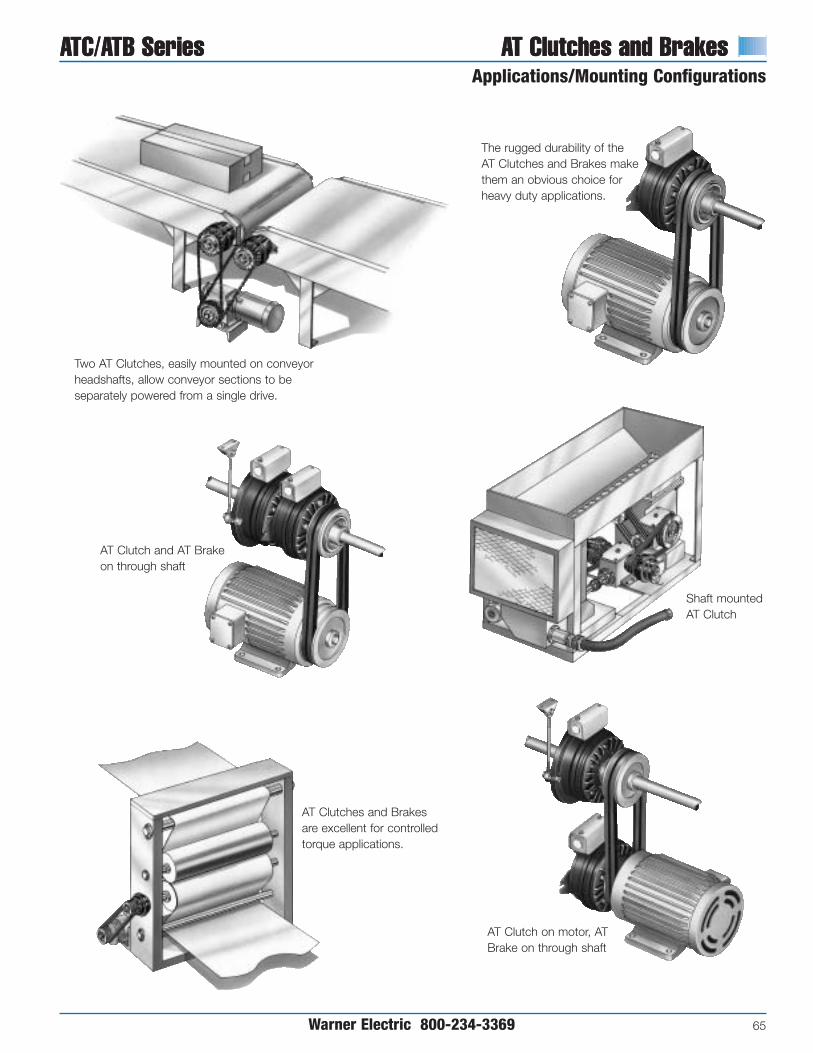
ATC/ATB Series AT Clutches and BrakesApplications/Mounting Configurations
ATC/ATB Series AT Clutches and Brakes
Warner Electric 800-234-3369 65
Two AT Clutches, easily mounted on conveyorheadshafts, allow conveyor sections to beseparately powered from a single drive.
AT Clutches and Brakesare excellent for controlledtorque applications.
Shaft mountedAT Clutch
AT Clutch on motor, ATBrake on through shaft
AT Clutch and AT Brakeon through shaft
The rugged durability of theAT Clutches and Brakes makethem an obvious choice forheavy duty applications.

AT Clutches and Brakes ATC/ATB SeriesPerformance Advantages
66 Warner Electric 800-234-3369
Principle of OperationEase of control is one of the mostoutstanding features of WarnerElectric brakes and clutches. Inoperation, a magnetic field isgenerated as soon as current flowsthrough the magnet coil. Themagnetic poles are molded into areplaceable disc with the frictionmaterial. The electromagnetic forcefrom the field or magnet passesthrough the poles to attract thearmature, clamping the twotogether tightly. Strength of themagnetic field is directly proportional to theamount of current applied. The full torquerange is completely controllable from 0 to100% simply by turning the knob on theappropriate Warner Electric control.
Replaceable Friction DiscsThe AT Electric Clutches and Brakesfeature a patented replaceable frictionface incorporating a unique combinationof electromagnetic poles and friction
material in a simplecomponent. Easilyvisible friction discindicates whenreplacement isnecessary–providing ahelpful maintenanceguide. The results arelong life, efficientoperation, andminimal down time.Rebuild kits of pre-selected partsenhance unit life.
The split friction disc and armature arereplaceable without unit disassembly inless than 5 minutes in most applications.
Autogap™ AlignmentProvides for automatic adjustment of theair gap between the wearing frictionsurfaces. Engagement times are consistentto maintain stopping and starting accuracyfor the entire life of the unit.
Technical ConsiderationsMost normal duty applications will usuallyrequire a selection based only onhorsepower and speed at the clutch orbrake location as indicated on pages 67,68 and 72. However, to insure the best
possible overall performance and the mostcost effective unit size selection, additionalfactors should be considered. The maincriteria are:
1. Horsepower
2. RPM
3. System inertia at the clutch or brake
4. Cycle rate and start/stop time
5. Static torque requirement, if any.
For instance, the HP and RPM sizingderived from the selection chart on page68, may be different than the size requiredby the system inertia and cycle rate. In thatcase, the proper size is the larger size unit.Additional application information makes avery accurate and exacting unit sizeselection possible. To achieve this, systeminertia and required cycle rate must beknown.
Cycle RateCycle rate capability is often an importantselection criteria. Cycle rate is usuallydefined as the number of times the clutchand/or brake is switched on and off in aminute or Cycles per Minute (CPM). Inorder to determine the correct size unit,both required cycle rate and reflectedinertia must be known. The inertia of theAT clutch/brake components has beenfactored into the charts, so these need notbe considered. To determine size from thecharts:
1. Estimate the size clutch or brake.
2. Read the chart for that size. Theintersection of the reflected inertia (lb.ft.2) and speed difference (RPM) lineswill indicate the maximum cycle rate forthat size unit.
3. Compare cycle rates. If the cycle raterequired falls within the units capability,proceed to step 4 below. If the requiredcycle rate is above the size selected,go to the next larger AT unit.
4. Verify selection. Compare the sizeselected in 2 and 3 above to theHorsepower/Speed simple selectionmade on page 68. If the size selectedis not the same, choose the largerselected by the two methods.
Easy sheavemountingOptional sheavesand pulleys available
AutogapsTM
automaticallyadjust for wear

ATC/ATB Series AT Clutches and BrakesPerformance Curves
Warner Electric 800-234-3369 67
Cycle Rate Capability Stop/Start Time Capability
0.1 0.2 0.3 0.5
Sp
eed
Dif
fere
nce
(R
PM
)
Inertia (lb. ft.2)
100
600
9001200
1800
3600
1 2 3 54 10 20 30 5040 100 300 500 1000 2000
0.1 0.2 0.3 0.5
Sp
eed
Dif
fere
nce
(R
PM
)
Inertia (lb. ft.2)
600
9001200
1800
3600
1 2 3 54 10 20 30 5040 100 300 500 1000 2000
0.1 0.2 0.3 0.5
Sp
eed
Dif
fere
nce
(R
PM
)
Inertia (lb. ft.2)
600
9001200
1800
3600
1 2 3 54 10 20 30 5040 100 300 500 1000 2000 0.1 0.2 0.3 0.5
Sp
eed
Dif
fere
nce
(R
PM
)
Inertia (lb. ft.2)
600
9001200
1800
3600
1 2 3 54 10 20 30 5040 100 300 500 1000 2000
0.1 0.2 0.3 0.5
Sp
eed
Dif
fere
nce
(R
PM
)
Inertia (lb. ft.2)
600
9001200
1800
3600
1 2 3 54 10 20 30 5040 100 300 500 1000 2000
0.1 0.2 0.3 0.5
Sp
eed
Dif
fere
nce
(R
PM
)
Inertia (lb. ft.2)
600
9001200
1800
3600
1 2 3 54 10 20 30 5040 100 300 500 1000 2000
100
100 100
100
100
ATC 25/ATB 25 ATC 25/ATB 25
ATC 55/ATB 55 ATC 55/ATB 55
ATC 115/ATB 115 ATC 115/ATB 115
60 CPM30 CPM
20 CPM10 CPM
5 CPM1 CPM
60 CPM30 CPM
20 CPM10 CPM
5 CPM1 CPM
60 CPM30 CPM
20 CPM10 CPM
5 CPM60 CPM
1 CPM
.25 Sec.
.5 Sec.
1 Sec.
5 Sec.
10 Sec.
.25 Sec.
.25 Sec.
.5 Sec.
1 Sec.
5 Sec.
10 Sec.
.5 Sec.
1 Sec.
5 Sec.
10 Sec.
Start/Stop TimesIn some applications, accelerating and/ordecelerating the load within a specific timeis a critical factor. In these start/stop timecharts, AT unit inertias have already beenfactored in, so only reflected inertia needbe considered. Selection for start/stoptimes can be made as follows:
1. Estimate the size clutch or brakerequired.
2. Read the chart for that size. Crossreference the speed difference (RPM)with the reflected inertia (lb. ft.2 ) to findthe maximum start/stop capability forthat size unit.
3. Compare start/stop times. If thestart/stop time is equal to or less thanthat required for that application, thecorrect size unit has been selected. Ifshorter start/stop times are required,repeat the procedure on the chart forthe next larger size unit.
4. Verify the selection. Compare the unitsize chosen in steps 1, 2, and 3 to theunit size chosen by the simpleHorsepower/Speed method on page68. If the sizes selected are notidentical, choose the larger selected bythe two methods.
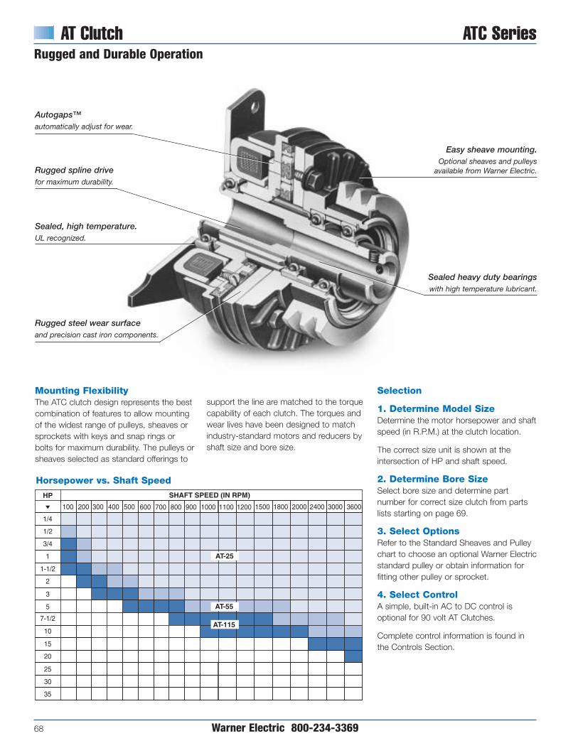
AT Clutch ATC SeriesRugged and Durable Operation
68 Warner Electric 800-234-3369
Clutch HP/SS Chart
AT-205
AT-305
1/4
1/2
3/4
1
1-1/2
2
3
5
7-1/2
10
15
20
25
30
35
HP
Horsepower vs. Shaft Speed
100 600 1000 1100 1200 1500 1800 2000 2400 3000 3600200 300 400 500 700 800 900
SHAFT SPEED (IN RPM)
AT-25
AT-55
AT-115
Mounting FlexibilityThe ATC clutch design represents the bestcombination of features to allow mountingof the widest range of pulleys, sheaves orsprockets with keys and snap rings orbolts for maximum durability. The pulleys orsheaves selected as standard offerings to
Selection
1. Determine Model SizeDetermine the motor horsepower and shaftspeed (in R.P.M.) at the clutch location.
The correct size unit is shown at theintersection of HP and shaft speed.
2. Determine Bore SizeSelect bore size and determine partnumber for correct size clutch from partslists starting on page 69.
3. Select OptionsRefer to the Standard Sheaves and Pulleychart to choose an optional Warner Electricstandard pulley or obtain information forfitting other pulley or sprocket.
4. Select ControlA simple, built-in AC to DC control isoptional for 90 volt AT Clutches.
Complete control information is found inthe Controls Section.
Horsepower vs. Shaft Speed
support the line are matched to the torquecapability of each clutch. The torques andwear lives have been designed to matchindustry-standard motors and reducers byshaft size and bore size.
Autogaps™automatically adjust for wear.
Rugged spline drivefor maximum durability.
Sealed, high temperature.UL recognized.
Rugged steel wear surfaceand precision cast iron components.
Sealed heavy duty bearingswith high temperature lubricant.
Easy sheave mounting.Optional sheaves and pulleys
available from Warner Electric.

ATC Series AT ClutchSelection/Ordering Information
Warner Electric 800-234-3369 69
Standard Sheaves and Pulleys
Sheave Clutch or No. Grooves Part Pitch DimensionsPulley Type Brake Size No. Teeth Number Diameter Width O.D.
25 26H100 689-0256 4.138" 1.312" 4.244"Timing Belt 55 30H100 689-0278 4.755" 1.312" 4.881"
115 40H150 689-0257 6.366" 1.812" 6.472"
25 1G3.60 689-0267 3.600" .750" 3.850"“A” Section 55 2G4.80 689-0308 4.800" 1.445" 5.050"
115 3G6.00 689-0271 6.000" 2.000" 6.250"
25 1G3.65 689-0259 3.600" .695" 3.650"“3V” Section 55 2G4.12 689-0315 4.070" 1.094" 4.120"
115 3G5.30 689-0263 5.250" 1.515" 5.300"
“B” Section 115 2G6.00 689-0275 6.000" 1.750" 6.350"
Optional Equipment
Part Numbers
Model Bore VoltageSize Size DC Part No.
6 5161-271-0021/2" 24 5161-271-010
90 5161-271-0036 5161-271-004
5/8" 24 5161-271-011
ATC-2590 5161-271-0056 5161-271-006
3/4" 24 5161-271-01290 5161-271-0076 5161-271-008
7/8" 24 5161-271-01390 5161-271-009
6 5162-271-0023/4" 24 5162-271-010
90 5162-271-0036 5162-271-004
7/8" 24 5162-271-011ATC-55 90 5162-271-005
6 5162-271-0061" 24 5162-271-012
90 5162-271-0076 5162-271-008
1-1/8" 24 5162-271-01390 5162-271-009
6 5163-271-0021-1/8" 24 5163-271-010
90 5163-271-0036 5163-271-004
1-1/4" 24 5163-271-011ATC-115 90 5163-271-005
6 5163-271-0061-3/8" 24 5163-271-012
90 5163-271-0076 5163-271-008
1-1/2" 24 5163-271-01390 5163-271-009
Minimum Size Sprockets for Pilot Mount
Clutch SizeChain Size 25 55 115
25 54T — —
35 35T 40T —
41/40 28T 30T 40T
50 22T 24T 30T
60 — 20T 24T
80 — — 20T
100 — — —
120 — — —
Bore size2.500/2.502/ 3.000/3.002/ 4.00/4.002/
(63.500/63.551) (76.200/76.251) (101.600/101.651)
Bolt Circle 3.000/(76.200) 3.500/(88.900) 4.750/(120.650)
No. Holes and Sizes (3) .281/[(3) 7.144] (4) .281/[(4) 7.144] (4) .344/[(4) 8.731]
Note: Spacer may be required to avoid chain interference with clutch.
Other Sheaves,Pulleys and SprocketsThe unique AT Clutch design permitsthe installation of any customerprovided sheave, pulley or sprocketthat can be bored out and key seatedto the Bore-to-Size dimensions shownon page 71.
SprocketsThe AT clutch design permits installationof customer supplied sprockets. Minimumsize sprocket requirements found in thechart below can be bored out and drilledto the dimensions in that chart.

AT Clutch ATC SeriesATC-25, ATC-55, ATC-115
70 Warner Electric 800-234-3369
Clearancefor 1/4" bolts
O
T
OptionalRestraining Strap
G N
H 7.50Typ
S
R
OptionalConduitBox
F 0.875
Wire Protectorincluded withClutch
Key and Retaining Ringincluded with Clutch
1.544
SeeDetailView
AC
M
L
KP
B
DJ
E
Q
WU
V90°
1/4-20 UNC thru.(2) Jackscrew Holeson X dia.Detail View
Bore-to-size Requirements
Bore-to-size datadrawing for pulley,sheaves, andsprockets. See Bore-to-size data on page 71.
Specifications
Model Size Voltage DC Unit Inertia*-WR2 (lb.ft.2) Max. RPM Weight (lbs.) Static Torque (lb.ft.) Dynamic Torque @ 1800 RPM6 .048 3600 8 25 12 lb. ft.
25 24 Clutch .048 3600 8 25 12 lb. ft.90 .048 3600 8 25 12 lb. ft.
6 .173 3600 18 55 20 lb. ft.55 24 Clutch .173 3600 18 55 20 lb. ft.
90 .173 3600 18 55 20 lb. ft.
6 .483 3600 28 115 30 lb. ft.115 24 Clutch .483 3600 28 115 30 lb. ft.
90 .483 3600 28 115 30 lb. ft.

ATC Series AT ClutchATC-25, ATC-55, ATC115
Warner Electric 800-234-3369 71
( ) denotes millimeters
A B C D E F G H J K L M TMax. Nom. Max.
Model Dia. Max. Nom. Dia. Max. Max. Max. Max. Dia. Max. Nom. Max. Nom.
253.60 4.39 2.375 1.080 4.748 3.767 3.282 5.11 4.822 1.68 1.003/.991 .715/.703 .375
(91.44) (111.51) (60.33) (27.43) (120.60) (95.68) (83.36) (129.79) (122.49) (42.67) (25.48/25.17) (18.16/17.86) (9.53)
553.95 4.935 2.925 1.40 5.182 3.767 4.032 5.11 6.275 1.817 1.113/1.101
–.375
(100.33) (125.35) (74.30) 35.56) (131.62) (95.682) (102.412) (129.792) (159.39) (46.152) (28.27/27.97) (9.53)
1155.254 5.977 3.102 1.86 6.089 3.767 4.246 10.11 7.906 2.467 1.539/1.523
–.375
(133.452) (151.822) (78.792) (47.242) (154.662) (95.682) (107.852) (256.792) (200.812) (62.662) (39.09/38.68) (9.53)
No. of N Max. Bolt O P Q R SModel Holes Thread Size Depth Circle Nom. Nom. Nom. Min. Min.
25 3 1/4-20 .500 3.00.500 .036 3.586 .752 .279(12.7) (0.91) (91.10) (19.08 (7.09)
55 4 1/4-20 .635 3.50.500 .081 4.156 .722 .265(12.7) (2.06) (105.56) (18.34) (6.73)
115 4 5/16-18 .830 4.75.500 .237 4.927 .504 .265(12.7) (6.02) (125.15) (12.80) (6.73)
Bore to Size Data
U V W XModel Bore Dia. Keyway Height Keyway Width Bolt Circle
252.502/2.500 2.601/2.591 .1905/.1855 3.00(63.55/63.50) (66.06/65.81) (4.84/4.79) (76.20)
553.002/3.000 3.099/3.089 .1905/.1885 3.50(76.25/76.20) (78.71/78.46) (4.84/4.79) (88.90)
1154.002/4.000 4.127/4.117 .378/.376 4.50
(101.65/101.60) (104.83/104.57) (9.60.9.55) (114.30)
Bore Size and Keyways
Size Unit Bore Key(in.) (mm)
.5025 12.761/8 Sq.
ATC-25.5005 12.71.6275 15.94
3/16 Sq..6255 15.89
ATC-25 .7525 19.113/16 Sq.ATC-55 .7505 19.06
ATC-25 .8775 22.293/16 Sq.ATC-55 .8755 22.24
ATC-551.0025 25.46
1/4 Sq.1.0005 25.41
ATC-55 1.1275 28.641/4 Sq.ATC-115 1.1255 28.59
1.2525 31.811/4 Sq.1.2505 31.76
ATC-1151.3775 34.99
5/16 Sq.1.3755 34.941.5025 38.16
3/8 Sq.1.5005 38.11

AT Brake ATB SeriesReplaceable Armature Faces AssureMinimum Downtime
72 Warner Electric 800-234-3369
Ordering InformationPart NumbersModel Bore VoltageSize Size DC Part No.
6 5191-170-0021/2” 24 5191-170-010
90 5191-170-0036 5191-170-004
5/8” 24 5191-170-011
ATB-2590 5191-170-0056 5191-170-006
3/4” 24 5191-170-01290 5191-170-0076 5191-170-008
7/8” 24 5191-170-01390 5191-170-009
6 5192-170-0023/4” 24 5192-170-010
90 5192-170-0036 5192-170-004
7/8” 24 5192-170-011
ATB-5590 5192-170-0056 5192-170-006
1” 24 5192-170-01290 5192-170-0076 5192-170-008
1-1/8” 24 5192-170-01390 5192-170-009
6 5193-170-0021-1/8” 24 5193-170-010
90 5193-170-0036 5193-170-004
1-1/4” 24 5193-170-011ATB-115 90 5193-170-005
6 5193-170-0061-3/8” 24 5193-170-012
90 5193-170-0076 5193-170-008
1-1/2” 24 5193-170-01390 5193-170-009
ATB Brakes are completely assembled atthe factory and have been specificallydesigned to match the torque ratings ofstandard motors, reducers, and otherpower transmission components. Theyfeature a replaceable friction face. whichhas been designed to provide superiorwear life with reduced engagment noiselevel wear and consistent torque capacity.Wear surfaces can, in many cases, bereplaced without removing the unit fromthe shaft.
Selection
1. Determine Model SizeDetermine the motor horsepower and shaftspeed (in R.P.M.) at the brake location.
The correct size unit is shown at theintersection of HP and shaft speed in thechart below.
2. Determine Bore SizeSelect bore size and determine partnumber for correct size brake from partslists starting on this page.
3. Select OptionsRefer to the Standard Sheaves and Pulleychart to choose an optional WarnerElectric standard pulley or obtaininformation for fitting other pulleys orsprockets.
AT Brake HP/SS Chart11/14/99page 108
AT-205
AT-305
1/4
1/2
3/4
1
1-1/2
2
3
5
7-1/2
10
15
20
25
30
35
HP
Horsepower vs. Shaft Speed
100 600 1000 1100 1200 1500 1800 2000 2400 3000 3600200 300 400 500 700 800 900
SHAFT SPEED (IN RPM)
AT-25
AT-55
AT-115
Horsepower vs. Shaft Speed
AutogapsTM automatically adjust forwear. Consistent engagement timesand repeatability for the life of the unit.
Rugged, two piece replaceable steelwear surface and precision cast ironcomponents. Superior wear life,torque capacity and magneticcharacterisitcs.
Two piece molded friction disc replaceablewithout disassembly of unit in mostapplications. Long life, low noise.
Rugged spline drivefor maximum durability.
Sealed heavy duty bearing withhigh temperature lubricantmaintain tight concentricitiesand running efficiency.
Sealed, high temperaturecoil with tough teflon leadwires for easy powerhookup. UL recognized.
Shaft mounted withtorque arm restraint.
4. Select ControlA simple, built-in AC to DC control isoptional for 90 volt AT Brakes.
Complete control information is found inthe Controls Section. Selection is byrequired function.

ATB Series AT BrakeATB-25, ATB-55, ATB-115
Warner Electric 800-234-3369 73
Service Parts
Bore Sizes and Keyways
Size Unit Bore Key.5025 12.76
1/8 Sq.ATB-25
.5005 12.71
.6275 15.943/16 Sq..6255 15.89
ATB-25 .7525 19.113/16 Sq.ATB-55 .7505 19.06
ATB-25 .8775 22.29 3/16 Sq.ATB-55 .8755 22.24
ATB-551.0025 25.46 1/4 Sq.1.0005 25.41
ATB-55 1.1275 28.64 1/4 Sq.ATB-115 1.1255 28.59
1.2525 31.811/4 Sq.1.2505 31.76
ATB-1151.3775 34.99
5/16 Sq.1.3755 34.941.5025 38.16
3/8 Sq.1.5005 38.11
A B C D E F G HMax. Min.
Model Dia. Max. Dia. Max. Nom. Max. Nom. Max.
254.822 2.843 .354 1.345 4.748 3.767 2.406 9.03
(122.48) (72.21) (8.99) (34.16) (120.60) (95.68) (61.11) (229.36)
556.271 3.224 .281 1.756 5.37 3.767 3.00 11.19
(159.28) (91.89) (7.14) (44.83) (136.40) (95.68) (76.20) (284.23)
1157.906 4.115 .687 2.150 6.278 3.767 3.781 11.19
(200.81) (104.52) (17.45) (54.61) (159.46) (95.68) (96.04) (284.23)
I J K L M N O PMax. Min.
Model Dia. Nom. Nom. Max. Nom. Min. Nom. Max.
255.760 1.544 1.500 .195 3.586 .280 .312 2.765
(146.30) (39.22) (38.10) (4.95) (91.08) (7.11) (7.92) (70.23)
557.375 1.544 1.50 .491 4.208 .375 .375 3.105
(187.33) (39.22) (38.10) (12.47) (106.88) (9.53) (9.53) (78.87)
1159.00 1.544 1.50 .463 5.116 .375 .375 3.955
(228.60) (39.22) (38.10) (11.76) (129.95) (9.53) (9.53) (100.46)
Wire Protectorincluded withBrake
OptionalConduit Box
F
G
H
B
A DP
LC
I
E
M
J
Wear Indicator
Friction Face
Armature
.875(22.25)
O
K
Clearancefor 1/4" bolts
OptionalTorque Arm
N
A-112
Specifications
Model Size Voltage DC Static Torque lb. ft. Max. RPM Weight lbs. Inertia–WR2 lb.-ft.2 Dynamic Torque @ 1800 RPM25 6, 24 or 90 25 3600 7 .038 12 lb. ft.
55 6, 24 or 90 55 3600 15 .126 20 lb. ft.
115 6, 24 or 90 115 3600 24 .383 30 lb. ft.
( ) denotes millimeters

Packaged Performance Products
74 Warner Electric 800-234-3369
Shaft Mounted Clutches
Warner Electric’s packaged stationaryfield clutches are factory assembled andburnished to deliver the maximum ratedtorque immediately. In addition, apackaged product assures that allengineering factors regarding the properalignment of components to one anotherhave been established at the factory.This allows the unit to be ‘slid on theshaft’ after being shipped to you. Theproper alignment of components iscritical to achieving maximum torqueand assuring long life.
Features
• No assembly required
• Burnished for ‘out-of-the box’ torque
• Anti-backlash armatures standard
• Ball bearing mounted field andarmature hub
• Two sizes available250 – 70 in.lb. static torque400 – 270 in.lb.static torque
• Standard bore sizes and voltages
No brushes to wear out
Besides saving valuable assembly andrun-in time, the SFP clutchesincorporate an original Warner Electricconcept. The concept of the stationaryfield eliminates the need for brushes.Brushes can be a high maintenanceitem in an electromagnetic clutchbecause of the mechanical friction seenat the collector ring. There is nomechanical friction with the stationaryfield design. In sum, all of the bestpossible features wrapped up into onecompact package - Warner Electric’sSFP.
SFP-250Three standard bore sizes: 3/8", 7/16", 1/2" *
Three standard voltages:6, 24 and 90 Volts DC
*Consult factory for 5/8” availability
SFP-400Five standard bore sizes:1/2", 5/8", 3/4", 7/8", 1"
Three standard voltages:6, 24 and 90 Volts DC
Applications
• Controlled, soft starts
• Speed variation
• Reversing
• Overload disconnect
• High cycling
Functions
• Packaging equipment
• Film readers
• Medical equipment
• Conveyors
• Sorting/feeding equipment
• Textile machinery

Packaged Performance Products
Warner Electric 800-234-3369 75
Specifications
Model Static Torque Max.RPM
SFP-250 70 in.lb. 7500SFP-400 270 in.lb. 5000
How to Order
1. Select the proper size from the chart(right).
2. Select the bore size and voltage.
3. Find the corresponding part numberfrom the table below.
4. Select a Warner Electric Control ifappropriate.
Tolerances
Model A Keyway Part Number
No. Bore B C 6V 24V 90V
.375” .0948 .421 5103-271-002 5103-271-006 5103-271-010
SFP-250.438” .126 .479 5103-271-003 5103-271-007 5103-271-011
.500” .126 .560 5103-271-004 5103-271-008 5103-271-012
.6255 .1885 .678 5103-271-005 5103-271-009 5103-271-013
.5005” .125 .560 5104-271-006 5104-271-016 5104-271-021
.6255” .1875 .709 5104-271-007 5104-271-017 5104-271-022
SFP-400 .7505” .1875 .837 5104-271-008 5104-271-018 5104-271-023
.8755” .1875 .964 5104-271-009 5104-271-019 5104-271-024
1.0005” .1875 1.090 5104-271-010 5104-271-020 5104-271-025
1/50
1/20
1/12
1/8
1/6
1/4
1/3
1/2
3/4
1
1-1/2
2
3
HP
100 600 1000 1100 1200 1500 1800 2000 2400 3000 3600 4000 4600 5000200 300 400 500 700 800 900
SHAFT SPEED AT CLUTCH (IN RPM)
250
400
SFP-250
SFP-400
+.002–.000B
+.010–.000C
+.002–.000A
3x #10-32UNF-2B
2x #10-32UNF-2BSet Screws
+.002–.000B
+.010–.000C
+.002–.000øA
ø2.000
Collar Required on .500and .625 Bores Only
.80
ø 1.498 ± .001
.17
1.64
2.79
.47
.06
ø.200 Max..50
.25R1 .563
1.75
.33 .24°
ø.635
ø2.645 Max.
Optional Conduit Box5200-101-010
3.75 (95.25) Nom.
4.69(119.13)
Max.
ø .192(4.88)Min.
R2 .312(58.72)Nom.
ø4.290 (108.97) Max.
45°
3x 1/4-20 UNC-2B.270 (6.86) Max. Full Thread
Equally Spaced onø3.500 (88.9)ø.014 (.36) M
1.55(39.37)Nom.
.955(24.26)Nom..060
(1.52)Nom.
.014(.35)Min.
1.00(25.4)Nom.
.525(13.3)Max.
2x 1/4-20Setscrew
2.998 ± .001(76.15 ± .025)
1.80(45.72)Nom.
3.070 (77.98) Max.
ø1.20(30.48)
Min.

Electro Pack EP SeriesBase Mounted Clutch/BrakeCombinations in a Rugged Housing
76 Warner Electric 800-234-3369
Electro Packs are rugged, pre-assembled clutchand brake combinations in an enclosed, footmounted housing.
They are factory aligned and pre-assembled andhave been designed to mate easily with industrystandard motors and reducers with v-belts, pulleys,chain and sprockets, in line couplings and timingbelt drives.
Features
• Bolt-it-down and wire-it-up . . . it’s ready to go!
• Maintenance free
• A wide torque range from 15 lb. in. to 1350 lb. ft.
Meets electrical codesUL Listed or CSA Certified.
Pre-packagedOver 20 majorcomponents havebeen pre-engineeredand pre-assembled ina typical Electro Pack.Ready-to-go, straightfrom the box.
Brake output shaft
Foot mountedBolt-it-down and wire-it-up. Allows forquick replacement/reduced downtime.
Maintenance freeNever needs lubrication.
Self-adjusting for wear ofclutch-brake friction faces.
Consistent performance.
Clutch input shaft
Heavy duty bearingsProperly aligned for
maximum performance.
Typical Application
A foot mounted Electro Pack combines witha motor in a parallel shaft drive application.

EP Series Electro PackSelection/Ordering Information
Warner Electric 800-234-3369 77
Part Numbers
Model VoltageNo. DC Part No.
6 5633-273-002EP-170 24 5633-273-003
90 5633-273-005
6 5130-273-031EP-250 24 5130-273-032
90 5130-273-034
6 5131-273-009EP-400 24 5131-273-010
90 5131-273-011
6 5230-273-003EP-500 24 5230-273-011
90 5230-273-002
6 5231-273-003EP-825 24 5231-273-004
90 5231-273-002
6 5232-273-003EP-1000 24 5232-273-005
90 5232-273-002
EP-15256 5234-273-00390 5234-273-00224 5234-273-017EP-1525HT90 5234-273-012
When ordering, specify size, voltage, and partnumbers.
Selection ProcedureDetermine the shaft speed at the ElectroPack location. The number listed at theintersection of horsepower and speed isthe size Electro Pack you require.
1/501/201/121/81/61/41/31/23/41
1-1/2235
7-1/210152025
Horsepower vs. Shaft Speed
HP
3040
100 1000200 300 400 500 600 700 800 900 1100 1200 1500 1800 2000 2400 3000 3600 4000 4500 5000
SHAFT SPEED AT CLUTCH (IN RPM)
EP-170
EP-250
EP-400
EP-500
EP-825
EP-1000
EP-1525
EP-1525HT
Horsepower vs. Shaft Speed
Specifications
Electro-Pack Size Horsepower @ 1800 RPM Static Torque Max. RPM Voltage DC
EP-170 1/8 15 lb. in. 10,000 6, 24 or 90
EP-250 1/2 70 lb. in. 7,500 6, 24 or 90
EP-400 1 270 lb. in. 4.500 6, 24 or 90
EP-500 2 50/40 lb. ft. 4,000 6, 24 or 90
EP-825 7-1/2 125 lb. ft. 3,600 6, 24 or 90
EP-1000 10 240 lb. ft. 3,000 6, 24 or 90
EP-1525 25 700 lb. ft. 1,800 6 or 90
EP-1525HT 401350 lb. ft. clutch
1,800 24, 90700 lb. ft. brake

Electro Pack EP SeriesEP-170, EP-250, EP-400
78 Warner Electric 800-234-3369
page 114
Output
A
B
C
D
H
E
G
F E
D
C
B
Input
Brake ClutchO
All dimensions are nominal, unless otherwise noted.
Size A B C Min. D E F G Max. H I J K L M N O3/32 x .3745 .250 Wide 1.662 1/2 14 NPT
170 3/64 .3735 .750 1.406 2.203 1.500 6.000 (4 slots) 3.437 1.652 .312 1.110 2.220 3.250 Conduit x 2Dia.
1/8 x .4995 .312 Wide 2.318 1/2 14 NPT250 1/16 .4985 1.250 2.468 3.312 2.250 8.968 (4 slots) 5.281 2.308 .375 1.625 3.250 4.250 Conduit x 2
Dia.
3/16 x .7495 .312 Wide 3.474 1/2 14 NPT400 3/16 x .7485 1.875 3.515 4.593 2.500 11.781 (4 slots) 6.937 3.464 .500 2.578 5.156 6.000 Conduit x 2
1-1/2
11/11/99page 115
MN
L
K
J
I
Specifications
Inertia*–WR2 (lb-in2)Model Size Voltage DC Static Torque lb. in. Output Input Max. RPM Weight lbs.
6 15 .031 .036 10,000 2.5EP-170 24 15 .031 .036 10,000 2.5
90 15 .031 .036 10,000 2.5
6 70 .331 .293 7,500 7.1EP-250 24 70 .331 .293 7,500 7.1
90 70 .331 .293 7,500 7.1
6 270 2.566 2.222 4,500 19.7EP-400 24 270 2.566 2.222 4,500 19.7
90 270 2.566 2.222 4,500 19.7

EP Series Electro PackEP-500
Warner Electric 800-234-3369 79
Brake Clutch
InputOutputA
D
C C
E F E
G
B
H
N
ML K
J
I
B
C
O
All dimensions are nominal, unless otherwise noted.
Size A B C D E F G H N ODia. Min. Max. Dia. Max. Dia. I J K L M Max.
3/16 x .8750 .406 4.004 1/2 NPT500 3/16 x .8745 2.218 3.796 4.234 7.000 15.515 (4 holes) 8.218 3.992 .500 2.937 5.875 8.734 Conduit x 2
1-3/4
Specifications
Model Size Voltage DC Unit Static Torque Inertia*–WR2 lb.ft.2 Max. RPM Weight lbs.
EP-500 6, 24 and 90Clutch 50 .039
4000 56Brake 40 .063

Electro Pack EP SeriesEP-825
80 Warner Electric 800-234-3369
B
C C
D
G
FE
N
M
L K
J
I
Output
A
Brake Clutch
Input
H
B
All dimensions are nominal, unless otherwise noted.
Size A B Dia. C Min. D Max. Dia. E F G Max. H I J K L M N Max.
8251/4 x 1.1250
2.875 5.000 5.734 8.500 20.031.406 Dia.
10.8125.254
.562 4.250 8.500 11.6091/4 x 2 1.1245 (4 holes) 5.252
Specifications EP-825
Model Voltage Static Inertia*–WR2 Max. WeightSize DC Unit Torque lb.ft.2 RPM lbs.
EP-825 6, 24 & 90Clutch 125 .651
3600 123Brake 125 .242
Output
Brake Clutch
Input
A
C
E F
H C
G
B D
N
I
J
KL
M
B
EP-1000
All dimensions are nominal, unless otherwise noted.
Size A B Dia. C Min. D Dia. E F G Max. H I J K L M N Max.1/2 x 1.875 .656 Dia. 6.255
1000 1/2 x 1.874 4.750 5.687 8.250 12.250 28.750 (4 holes) 12.500 6.241 .718 5.000 10.000 12.8753-3/4
Specifications EP-1000
Model Voltage Static Inertia*–WR2 (lb-ft2) Max. WeightSize DC Torque Output Side Input Side RPM lbs.
6 240 lb.ft. 1.45 1.01 3000 288EP-1000 24 240 lb.ft. 1.45 1.01 3000 288
90 240 lb.ft. 1.45 1.01 3000 288

EP Series Electro PackEP-1525, EP-1525HT
Warner Electric 800-234-3369 81
All dimensions are nominal, unless otherwise noted.
Size A B Dia. C Min. D Max. Dia. E F G Max. H I J K L M N Max.5/8 x 2.375 .796 Dia. 9.005
1525 5/8 x 2.374 5.750 7.500 8.468 16.500 33.500 (4 holes) 18.250 8.991 1.000 7.000 14.000 18.8754-1/4
5/8 x 2.375 .796 Dia. 9.0051525HT 5/8 x 2.374 5.750 7.500 8.468 16.500 33.500 (4 holes) 18.250 8.991 1.000 7.000 14.000 18.875
4-1/4
Specifications
Inertia*–WR2 lb.ft.2
Model Size Voltage DC Unit Static Torque lb.ft. Output Input Max. RPM Weight lbs.
EP-1525 6, 90Clutch 700
7.89 5.68 1800 655Brake 700
EP-1525HT 24, 90Clutch 1350
7.89 6.41 1800 656Brake 700
Output
Brake Clutch
Input
A
C
E F
H C
G
B D
N
I
J
KL
M
B

Electro Pack – Ceramic Faced EP-C SeriesPerformancePlus™ clutch/brakecombination in a foot mounted housing
82 Warner Electric 800-234-3369
PerformancePlus™ ElectroPacks use ceramicfriction systemtechnology. Thistechnology has beenin use for many years inspecialized applications. Throughthe development of advancedmanufacturing techniques, the improved performance of ceramic frictionmaterials are now available as standardproducts off the shelf.
PerformancePlus™ Electro Packs withceramic friction material are rugged, pre-assembled clutch and brake combinationsin base mounted housings. They havebeen designed to be installed in standardpower transmission systems with V-beltsand pulleys, chain and sprockets, in linecouplings, and timing belt drives.
When your application calls for a long lifeclutch/brake because of high cycle ratesor demanding consistency, choose thePerformancePlus solution.
• Bolt-it-down and wire-it-up . . . it’s ready to go!
• Available in two size; 170 and 250.Standard voltages are 24V and 90V DC.
• Maintenance free.
• Ideal for use with CBC 1000 indexersand CBC 700 OEX control.
PerformancePlus™ . . . the demandingapplication choice.
EP-C Cycle Repeat Chart11/14/99page 128
Sta
rt/S
top
Var
iati
on
Cycle Rate
LOW
<20 CPM >200
Ceramic
Standard
HIGH
EP-C Product Life Chart11/14/99page 128
Ceramic
Standard
Lif
e E
xpec
tan
cy
5x
3x
1x
Cycle Rate
LOW
<20 CPM >200
HIGH
Extended Life for HighCycle Rate Use
Ceramic faced clutches and brakes havebeen designed specifically for rapid cyclingapplications to satisfy today’s needs forhigh speed equipment. Ceramic frictionmaterial provides excellent wear resistancethat extends life 3 to 5 times that ofstandard clutch/brakes in demandingapplications.
Consistent Torqueand Cycle Repeatability
Preloaded armatures keep the ceramicfriction surfaces in light contact, providingconsistent torque and cycle-to-cyclerepeatability. Variation is reduced by up to30% over standard units.
Single point wire exit
Pre-packagedMajor components have beenpre-engineered and pre-assembled in a typical Electro Pack.Ready-to-go,straight from the box.
Foot mountedBolt-it-down, wire-it-up.
Heavy duty bearingsProperly aligned for
maximum performance.
Ceramic on ceramicfriction system
Longer life, andconsistent torque.
Preload armature springsFast response,
accurate repeatability,no adjustments for life of unit.
EP-C Product Life EP-C Cycle Repeat
<20 CPM >200Cycle Rate
<20 CPM >200Cycle Rate

EP-C Series Electro Pack – Ceramic FacedApplications/Selection
Warner Electric 800-234-3369 83
Horsepower vs. Shaft Speed
Typical ApplicationsControllabilitySmooth Start/StopWith the ceramic friction surfaces always incontact, dynamic torque response is fastand precise. When used with a CBC-700over-excitation control and CBC-1000programmable counter, exceptional closedloop clutch/brake performance can beachieved approaching that of moreexpensive motion control technologies –The PerformancePlus difference!
SelectionPerformancePlus Electro Packs are bestsuited for high energy applications wherelong life is a premium concern. The hardera ceramic friction surface is worked, themore wear life benefit is achieved. Forslower cycle rates, up to 75 cycles perminute, dependable standardclutch/brakes are still a good choice.
For high cycle rates and high energy use(generally more than 50 cycles/minute forEP-170’s and EP-250’s) PerformancePlusclutch/brakes are the choice.
Technical considerations for sizing andselection are torque and heat dissipation.Each merits careful consideration,especially heat dissipation. Overtemperature use will have an adverse effecton bearing life and coil wire insulationintegrity.
For proper sizing information, refer to theHorsepower vs. Shaft Speed chart, andthe technical sizing considerations below.When ordering, specify size, voltage, andpart number.
EP-C HP/Shaft Speed Chart11/14/99page 129
1/50
1/20
1/12
1/8
1/6
1/4
1/3
1/2
1
HP SHAFT SPEED AT CLUTCH (IN RPM)
Horsepower vs. Shaft Speed
100 200 300 400 500 600 700 800 900 1000 1100 1200 1500 1800 2000 2400 3000 3600 4000 4600 5000
EP-170-C
EP-250-C
Form, Fill and SealThe PerformancePlus™ Electro Packprovides high cycle rate indexing forpackaging and bagging operations.
Mail ProcessingThe PerformancePlus Electro Packprovides fast cycling and accuratestarting and stopping.

Electro Pack – Ceramic Faced EP-C SeriesSelection/Ordering Information
84 Warner Electric 800-234-3369
Heat Dissipation SizingFriction surfaces slip during the initialperiod of engagement and, as a result,heat is generated. The clutch/brakeselected must have a heat dissipationrating greater than the heat generated bythe application. Therefore, in high inertia orhigh cycle rate applications, it is necessaryto check the heat dissipation carefully.Inertia, speed and cycle rate are therequired parameters.
These curves show the heat dissipationcapability of the ceramic units.
Heat dissipation requirement is calculatedas follows:
E = 1.7 x WR2 x N x F100
where:E = Heat (lb.ft./min.)WR2 = Total reflected inertia at the
clutch/brake shaft. Include theclutch/brake output inertia. (lb.ft.2)
N = Speed in revolutions per minute.(RPM)
F = Cycle rate in cycles per minute.(CPM)
Compare the calculated heat generated inthe application to the unit ratings using theheat dissipation curves. Select theappropriate unit that has adequate heatdissipation ability.
Dynamic Torque SizingThese curves show the average dynamictorque during the slip period ofengagement. Find the dynamic torquevalue on the curve at the clutch/brakeinput speed.
For most applications, the correct sizeclutch/brake can be selected from thehorsepower/shaft speed selection chart.Determine the motor horsepower and theRPM at the clutch/brake. The correct sizeunit is shown at the intersection ofhorsepower and shaft speed.
If the static torque requirements areknown, refer to the technical ratings chartto select a unit.
Torque Ratings
Model Max. Static VoltageSize RPM Torque DC
EP-170-C 10,000 15 lb. in. 24 & 90
EP-250-C 7500 70 lb. in. 24 & 90
For some applications, the torquerequirement is determined by the timeallowed to accelerate and decelerate theload. (This time is generally specified inmilliseconds.) For these applications, it isnecessary to determine the torquerequirement based on load inertia and thetime allowed for engagement.
The torque requirements are calculated asfollows:T = WR2 x N
308 x twhere:T = Average Dynamic Torque (lb. ft.)
(For EP selection, multiply by 12 toconvert to units of lb. in.)
WR2 = Total reflected inertia at theclutch/brake shaft. Include theclutch/brake output inertia. (lb. ft.2)
N = Speed in revolutions per minute.(RPM)
t = Time allowed for the engagement(sec)
Compare the calculated torquerequirement with the average dynamictorque ratings. Select a unit with adequatetorque. If the unit selected on torque isdifferent than the unit selected based onheat, select the larger unit size.
Part Numbers
Model VoltageSize DC Part No.
EP-170-C24V P/N 5633-273-01890V P/N 5633-273-019
EP-250-C24V P/N 5130-273-05390V P/N 5130-273-054
EP-170-C Curve11/14/99page 130
0
Hea
t D
issi
pat
ion
(ft
. lb
./min
.)
Speed (RPM)
600
EP-170-CMaximum Speed 7500 rpm
700
800
900
1000
1100
1200
2000 4000 6000 8000 10000
EP-250-C Curve11/14/99page 130
0
Hea
t D
issi
pat
ion
(ft
. lb
./min
.)
Speed (RPM)
0
EP-250-CMaximum Speed 7500 rpm
1500 3000 4500 6000 7500
1000
2000
3000
4000
5000
6000
7000
8000
EP-170/250-C Dynamic Torque11/14/99page 130
0
Dyn
amic
To
rqu
e (l
b. i
n.)
Speed Difference in RPM
020 40 60 80 100
20
EP-170-C EP-250-CEP-170-C Maximum Speed 10000 rpmStatic Torque 15 lb. in.
EP-250-C Maximum Speed 7500 rpmStatic Torque 70 lb. in.
40
60
80
100
( )2
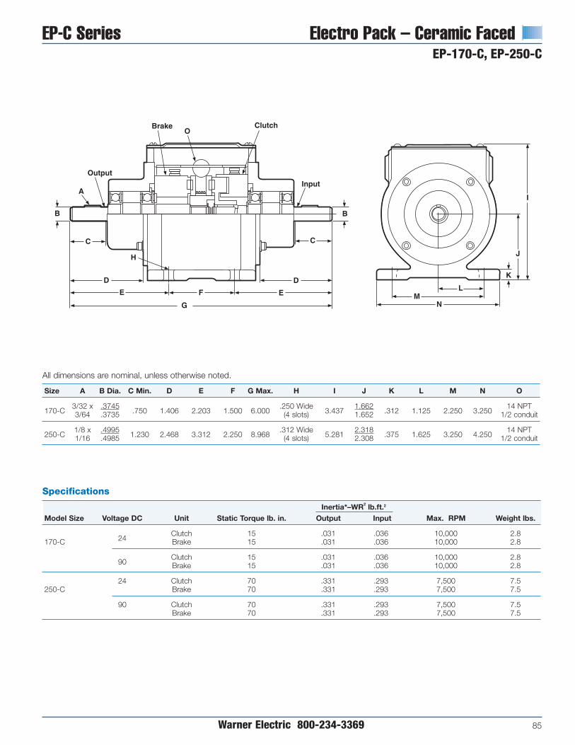
EP-C Series Electro Pack – Ceramic FacedEP-170-C, EP-250-C
Warner Electric 800-234-3369 85
All dimensions are nominal, unless otherwise noted.
Size A B Dia. C Min. D E F G Max. H I J K L M N O
170-C3/32 x .3745
.750 1.406 2.203 1.500 6.000.250 Wide
3.4371.662
.312 1.125 2.250 3.25014 NPT
3/64 .3735 (4 slots) 1.652 1/2 conduit
250-C1/8 x .4995
1.230 2.468 3.312 2.250 8.968.312 Wide
5.2812.318
.375 1.625 3.250 4.25014 NPT
1/16 .4985 (4 slots) 2.308 1/2 conduit
EP-170-C, 250-C Dim11/14/99page 131
MN
L
K
J
I
Output
A
B
C
D
H
E
G
F E
D
C
B
Input
Brake ClutchO
Specifications
Inertia*–WR2 lb.ft.2
Model Size Voltage DC Unit Static Torque lb. in. Output Input Max. RPM Weight lbs.
24Clutch 15 .031 .036 10,000 2.8
170-C Brake 15 .031 .036 10,000 2.8
90Clutch 15 .031 .036 10,000 2.8Brake 15 .031 .036 10,000 2.8
24 Clutch 70 .331 .293 7,500 7.5250-C Brake 70 .331 .293 7,500 7.5
90 Clutch 70 .331 .293 7,500 7.5Brake 70 .331 .293 7,500 7.5

Electrically Released Brakes Spring-SetSpring-Set Brakes for Static Holding andEmergency Stopping Applications
86 Warner Electric 800-234-3369
Statically engaged holding brakes areapplied where the rotating shaft needs tobe held after it has stopped and is ina static condition. Spring-set brakesautomatically stop and hold a load in theevent of power failure or other emergencystop situations. The spring clamping forceprovides holding torque until the brake iselectromagnetically released.
Although this brake should be engagedonly when the shaft is at rest, it canoccasionally act as a braking device on arotating shaft in an emergency situation.However, it is intended to be used forstatic applications.
This brake can be engaged when the shaftis at rest or when the shaft is in motion.
Machine ToolsERS Brakes are used on automatic tool changers tohold the load and maintain precise positioning accuracy.
ERD Typical ApplicationsThe Warner Electric line of ERDelectrically released, dynamic,spring-set brakes offers a high-performance, cost effectivesolution for power-off loadholding applications.
Hoist/WinchThe ERD with central torque adjustment can beused to consistency stop the rated load within afixed distance by dialing-in the proper torque levelon each production hoist. The addition of a manualrelease allows the load to be gradually and safelylowered to the ground in the event of power failure.
ERS SeriesStatic Engaged Brakes
ERD SeriesDual Purpose Engagement Brakes
ERS Typical ApplicationsThe Warner Electric ERS brakeis an ideal holding device inapplications where the motoris used to stop andaccurately positionthe load.

Spring-Set Electrically Released BrakesSpring Set Brakes
Warner Electric 800-234-3369 87
Overhead DoorThe ERD can be used in conjunction with a photo eye. In this application, whenever the lightbeam is broken, voltage to the brake is removed.The brake then applies and holds thedoor in position. Further, the manualrelease feature allows the operator toopen/close the door in the eventof a power failure.
Mobile EquipmentERS Brake, applied as a parking brake function onlift trucks, prevent rolling on slanted surfaceswithout the need for manual brake linkage orexpensive hydraulic brakes.
RoboticsERS Brakes can position and hold robotic equipment. Emergencybraking in the event of power loss can prevent damage to equipment.
Medical EquipmentERS brakes are used as parking brakes inwheelchairs and holding brakes in medicalapparatus such as mammography and catscan equipment.
Automated Material Handling SystemsERS Brakes hold rollers and lift mechanismsin place, and lock drive wheels in place.

Electrically Released Brakes ERS Series For Static Holding and Emergency Stopping
88 Warner Electric 800-234-3369
Magnet
Through holesStandard forflexible mounting.
Tapped holesStandard for
flexible mounting.
Friction discNon-asbestos frictionmaterial provides consistenttorque and long life.
Rugged spline driveFor high torque capabilitywith minimal backlash.No accurate axial hubpositioning required.
Class H magnet wireFor high temperature use.
Advanced corrosion protectionProvided for use in the toughest
industrial environments.
Large diameterThrough bore allows for drop-
through hub attachment.
End plate
Armature
TerminalsProvide easy electrical connections.
Packaged Performance
Warner Electric ERS Brakes are pre-assembled and burnished at the factory.The engineering is built-in. Each unit ischecked to ensure full rated torque rightout-of-the-box. Just secure the hub, boltdown the brake and wire it up. An optionalAC to DC control is available for use withall 90 volt units. Unique mounting featuresmake it easy to adapt the ERS Brake toalmost any application requirement.
ERS brakes are available in NEMA C-facemounted modules. Please consult factoryfor assistance.
Features• Designed for static holding operations
• Brake automatically engages whenpower is turned off
• Flexible mounting
• Electrically released – spring actuated
• Quick, quiet response for rapidengagement
• Compact, low profile design saves space
• Spline drive for high torque, minimalbacklash and long life
• Available in five sizes. Static torqueratings from 1.5 lb.ft. to 100 lb.ft.
• ERS-26 and ERS-42 UL approved.
Principle of Operation
ERS Brake torque is developed whensprings apply a clamping force betweenthe brake armature and the friction disc tothe end plate. Spring clamping forceprovides the holding torque of the brake.
To release the brake, electrical power isapplied to the magnet coil, generating amagnetic attractive force between thearmature and magnet. The magnetic forceovercomes the spring action, allowing thefriction disc to rotate freely.
“Electrically Released” brakes are sonamed because, when power is removed,the brake will stop and hold a load. Thisoccurs when power is lost eitherintentionally or unexpectedly due to amachine malfunction. When power is on,the brake electrically releases the load,allowing it to move freely.

ERS Series Electrically Released BrakesSelection
Warner Electric 800-234-3369 89
Step 1Holding TorqueSelect the size unit with torque capacityclosest to, but not less than, the holdingtorque required.
Brake Size Holding Torque Rating lb. ft.
ERS-26 1.5
ERS-42 7.0
ERS-49 15.0
ERS-57 34.0
ERS-68 100.0
1100
Brake Shaft Speed (RPM)
Lo
ad In
erti
a (l
b.f
t.2 )
ERS Selection Chart11/14/99page 137
200 400 600 1000 2000 3600
2
4
6
8
10
20
40
60
80
100ERS-68*
ERS-49,57
ERS-42
ERS-26
ERS-68* is only ratedup to 2000 RPM
Selection Procedure
ERS Brakes are available in five modelsfor an optimum size to match yourapplication requirements. Static torquecapabilities range from 1.5 lb.ft. to 100lb.ft.
The stopping function is an importantconsideration when deciding whichbrake to use. Will the brake be engagedand disengaged in a static condition(zero speed difference between thearmature disc and the friction disc)? Ifyes, the ERS Brake is the right choice.
Will the brake be normally engaged anddisengaged in a static condition withintermittent engagements dynamically?An emergency stop is a good example.If yes, the ERS Brake is the ideal choice.
Will the brake be subject to frequentdynamic braking action? If yes, then aWarner Electric ER, FB or ERD brakeshould be considered. The ERS Brake isnot the best choice for use as a highcycle rate dynamic brake.
Step 2System Inertia/Emergency StopIn an emergency stop (when power isinterrupted), the ERS Brake will engageand bring the load to a stop. To properlysize a brake for this application, load inertiamust be known. This is the total inertia ofall components which are to be brought toa stop. Adding the inertia of the ERS Brakeis not necessary; it has been included inthe selection chart.
With the load inertia and brake RPMknown, use the Emergency Stop SelectionChart to verify your brake selection. Simplylocate the intersection of your RPM andinertia and make sure you are not abovethe line for the brake you selected basedon Holding Torque (Step 1). If you areabove the line, select the brake designatedby the next higher line.
Emergency Stop Selection Chart
Sizing
Three factors are important for propersizing:
• Static holding torque requirement
• System inertia and brake RPM
• Stopping time
*ERS-68 is only rated up to 2000 RPM

Electrically Released Brakes ERS Series Selection
90 Warner Electric 800-234-3369
Step 3Stopping TimeIn some applications, it is desirable toknow how fast a brake will bring a load torest. The time to stop a load can bedetermined if the system inertia and brakeholding torque are known, according to thefollowing equation:
Where:
t = time to stop the load inseconds (sec.)
WR2 = system inertia at the brakelocation in pound-feet squared (lb.ft.2 )
N = speed of the brake shaft inrevolutions per minute (RPM)
T = rated brake holding torque inpound-feet (lb.ft.) See step 1,page 89.
Brake Apply/Release Time (Typical Values)
Brake Release Time Brake Apply Time (Seconds)(Seconds) Suppression Circuit A Suppression Circuit B
Model 24V 90V 24V 90V 24V 90V
ERS-26 0.03 0.03 0.04 0.04 0.01 0.01
ERS-42 0.05 0.06 0.10 0.10 0.01 0.02
ERS-49 0.07 0.08 0.15 0.15 0.02 0.02
ERS-57 0.11 0.11 0.15 0.15 0.02 0.02
ERS-68 0.16 0.20 0.20 0.20 0.03 0.03
Note: Release and Apply Times are armature engagement and release only.
t = WR2N308TERS Series Circuits
11/14/99page 138
Brake
Circuit A
1N4004
SwitchSignal
Brake
Circuit B
1N4004SwitchSignal
24V-1N536890V-1N5378
+ +
Actual stopping times depend onapplication variables, which include braketemperature, electrical suppression (seethe brake apply time data below),manufacturing tolerances, friction materialwear, etc. For this reason, specific stoptimes should be evaluated under actualapplication conditions.
If your application has special require-ments, please call us.
Step 4Select ControlConsult the Controls Section for controlproduct overview. The holding torque foran ERS is not adjustable. Therefore, anadjustable torque control is not required.

ERS Series Electrically Released BrakesArmatures/Hubs
Warner Electric 800-234-3369 91
ERS Extended Hub11/14/99page 139
ERS Mating Splined11/14/99page 139
Armature DrivesThe rugged splined drive provides flexibilityin selecting the most efficient method ofcoupling a load to the ERS Brake. Eachunit size has standard splined hubsavailable for common shaft sizes.
Recessed HubFor maximum spaceefficiency, mount hubon shaft, then mountbrake over hub.
Extended HubMount brake first, thenposition hub on shaft so hub is beyond the brake.
Mating SplinedMemberMachined spline on drive member matches armature spline tooperate brake.
Drive Hub/Spline and Interface Data
MatingA Key Set screw B C Set No. of Dia. Pressure
Model Bore (Not furnished) Orientation Nom. Nom. Screws Teeth Pitch Angle
.2525/ .2505 1/16 x 1/16 B
ERS-26 .3150/ .3130 1/16 x 1/16 B .600 .135 6-32 14 20/40 30°
.3775/ .3755 3/32 x 3/32 B
.3775/ .3755 3/32 x 3/32 A
.5025/ .5005 1/8 x 1/8 A
ERS-42 .6275/ .6255 3/16 x 3/16 A .700 .150 8-32 19 16/32 30°
.7525/ .7505 3/16 x 3/16 B
.3775/ .3755 3/32 x 3/32 A
.5025/ .5005 1/8 x 1/8 A
ERS-49 .6275/ .6255 3/16 x 3/16 A .800 .160 10-32 21 16/32 30°
.7525/ .7505 3/16 x 3/16 B
.8775/ .8755 3/16 x 3/16 B
.5025/ .5005 1/8 x 1/8 A
.6275/ .6255 3/16 x 3/16 A
ERS-57 .7525/ .7505 3/16 x 3/16 A .800 .190 1/4-20 15 10/20 30°
.8755/ .8755 3/16 x 3/16 B
1.0025/1.0005 1/4 x1/4 B
1.0025/1.0005 1/4 x 1/4 A
1.1275/1.1255 1/4 x 1/4 A
ERS-68 1.2525/1.2505 1/4 x 1/4 A .900 .190 1/4-20 22 10/20 30°
1.3775/1.3755 5/16 x 5/16 A
1.5025/1.5005 3/8 x 3/8 B
Note: Involute spline data per ANSI B92. 1a-1976, Class 5.
ERS Recessed Hub11/14/99page 139
Set Screw OrientationA
BacklashTotal unit backlash includes spline andarmature movement. It is typically lessthan one degree of rotation. Splinebacklash alone is typically 15 minutesof rotation or less.
ERS Screw Orientation11/14/99page 139
A
(2) Set Screws
A
C
B
Set Screw Orientation
B

Electrically Released Brakes ERS Series Mounting
92 Warner Electric 800-234-3369
Mounting OrientationERS Brakes are easily modified toaccommodate different mountingorientations. The brake can be mountedwith either face against the mountingsurface. The following mountings arepossible with the standard ERS brake.
Tapped HoleWorks well wherethrough boltmounting is im-practical.
Through BoltProvides rigidsupport. May bemounted on eitherside of brake.
Model A Nom. B Nom. C Holes D Nom.
ERS-26 4.000 .935 #4 .100
ERS-42 5.000 1.450 #6 .144
ERS-49 6.250 1.575 #8 .193
ERS-57 7.500 1.825 #10 .193
ERS-68 9.500 2.500 1/4 .224
Note: Holes for attaching flange to mounting surface to be provided by customer.
FlangeFlange mounting tobrake tapped holesfor most versatileattachment tomany differenthousings, motors,and frames.
Mounting Requirements1. Mounting surface to be perpendicular
to shaft with in .006" T.I.R.
2. Mounting holes to be within .015" trueposition to the shaft.
Optional Adapter Mounting Flange
ERS Through Belt11/15/99page 140
ERS Tapped Hole11/15/99page 140
ERS Flange11/15/99page 140
ERS Flange Dim11/15/99page 140
B
D
A
Exit forLead Wires
CDrilled andC’sunk holes
Bolt circlematchescorrespondingbrake

ERS Adapter Flange11/15/99page 141
ERS Series Electrically Released Brakes
Warner Electric 800-234-3369 93
Accessories
Adapter Flanges
Ordering Information
ERS Brake
Model Voltage Part Number
ERS-2624V 5158-170-01690V 5158-170-015
ERS-4224V 5151-170-00290V 5151-170-001
ERS-4924V 5155-170-00290V 5155-170-001
ERS-5724V 5153-170-00390V 5153-170-002
ERS-6824V 5154-170-00290V 5154-170-001
Splined Hub
Model Bore Dia. Part Number.250 5158-541-006
ERS-26 .312 5158-541-007.375 5158-541-008
.375 5151-541-002
ERS-42.500 5151-541-003.625 5151-541-004.750 5151-541-005
.375 5155-541-002
.500 5155-541-003ERS-49 .625 5155-541-004
.750 5155-541-005
.875 5155-541-006
.500 5153-541-004
.625 5153-541-005ERS-57 .750 5153-541-006
.875 5153-541-0071.000 5153-541-008
1.000 5154-541-0051.125 5154-541-006
ERS-68 1.250 5154-541-0071.375 5154-541-0081.500 5154-541-009
Special RequirementsERS Brake modifications such as metric bores, special voltages and low torqueunits are available. Consult factory.
ERS Conduit Box11/15/99page 141
ERS Controls11/15/99page 141
How to Order1. Verify that the brake is to be used in a
static holding/intermittent engagementapplication.
2. Choose the correct size ERS Brake fromthe selection procedure on pages 89-90.Select the correct brake part number forthe appropriate size and desiredoperating voltage.
3. Choose the splined hub part number forthe required bore diameter and unit size.
4. Select optional accessories, such as:adapter flange kit, AC to DC control andconduit box kit.
ControlsConduit Box
Model Part Number
Conduit Box 5154-101-001
Mounts toERS-49, 57 and 68 only
Model Part Number
CBC-100-1 6003-448-101
AC to DC Control
To be used with 90V ERS brakes
See the Controls Section on page 141 forcomplete information.
CBC-100-1 is 110 volt only
Ordering Information
Ordering the appropriate ERS brake foryour application is a simple, step-by-stepprocedure based on the intended func-tion, brake size, mounting configurationand operating voltage of the unit bestsuited for your needs, including anyoptional parts and accessories that youmay require. A Warner Electric salesrepresentative or distributor is alwayshappy to provide assistance.
Model Part Number
ERS-26 686-0182
ERS-42 686-0183
ERS-49 686-0184
ERS-57 686-0185
ERS-68 686-0186

Electrically Released Brakes ERS Series
94 Warner Electric 800-234-3369
ERS-26, ERS-42, ERS-49, ERS-57, ERS-68
ERS-26,42,49,57,68 Dim11/15/99page 142
C DA
0.875
E
G H
F
KJ
LOptional*
Conduit Box
45°
N(4) through holesequally spaced
P(4) tapped holesequally spaced
Q deep
MBolt Circle
Internal Involute Spline
0.328max.
B
*Available only for the ERS-49, 57, and 68 sizes

ERS Series Electrically Released BrakesERS-26, ERS-42, ERS-49, ERS-57, ERS-68
Warner Electric 800-234-3369 95
All dimensions are nominal, unless otherwise noted.
Model A Max. B Max. C D E F G
ERS-26 2.460 1.515 1.375 1.125 .860 1.250 —
ERS-42 3.520 1.595 2.000 1.600 1.375 1.255 —
ERS-49 4.270 1.767 2.600 1.750 1.500 1.332 3.625
ERS-57 5.020 1.937 3.240 2.100 1.750 1.503 4.000
ERS-68 6.520 2.030 4.504 2.800 2.425 1.565 4.750
Specifications
Power Current Resistance Inertia (lb.in.2) Weight (lbs.)Model Voltage DC (Watts) (Amperes) (Ohms) Static Torque (lb.ft.) Unit Hub Unit Hub
ERS-2624V 17.6 0.733 32.75
1.5 0.03 0.004 1.20 0.0690V 16.0 0.178 506.5
ERS-4224V 23.3 0.973 24.67
7 0.14 0.040 2.50 0.2090V 21.5 0.239 376.2
ERS-4924V 27.3 1.136 21.12
15 0.45 0.060 4.30 0.2590V 25.8 0.287 313.6
ERS-5724V 36.2 1.510 15.9
34 0.54 0.110 6.50 0.3890V 35.2 0.391 230.1
ERS-6824V 54.9 2.286 10.5
100 1.44 0.550 11.30 0.7590V 51.9 0.577 155.9
Model H J K L M Dia. N Dia. P Q
ERS-26 — — — — 2.125 .172/.164 4-40 .375
ERS-42 — — — — 3.125 .200/.190 6-32 .400
ERS-49 4.625 1.000 1.625 3.750 3.750 .228/.218 8-32 .400
ERS-57 5.000 1.170 1.625 3.750 4.500 .288/.278 10-24 .400
ERS-68 5.750 1.265 1.625 3.750 5.875 .413/.404 1/4-20 .500

Electrically Released Brakes Spring-Set Brake Modules SSBM Series- EM/ERS
96 Warner Electric 800-234-3369
Packaged Spring-Set BrakeModule for Holding Applications
The Spring-Set Brake Module is a NEMAC-face compatible unit designed toperform holding as well as occasionalemergency stopping functions, making itparticularly well-suited for motor brakeapplications. Because it is designed to bemounted on the front of a motor, it is anexcellent choice for retrofitting an existingmotor, or for use on custom designedmachinery.
Features
• NEMA C-face compatible mounting
• Performs holding functions withoccasional e-stops
• Completely assembled and preburnished at the factory
• Easy to install
• No adjustment required
• High torque, lead-free and asbestos-free friction material
Specifications
Holding Unit Unit
NEMA Torque Max Weight Inertia Voltage Power Current Resistance
Model Frame Size (ft-lbs) RPM (lbs) (lb-in2) (DC) (Watts) (Amperes) (Ohms) Part Number
EM-50/ERS-42 56C/48Y 7.0 3600 6.4 .29524 23.3 0.973 24.67 5370-170-122
90 21.5 0.239 376.2 5370-170-123
EM-50/ERS-49 56C/48Y 15.0 3600 8.2 .67324 27.3 1.136 21.12 5370-170-124
90 25.8 0.287 313.6 5370-170-125
EM-180/ERS-57182C/143TC
34.0 3600 10.4 .95524 36.2 1.510 15.90 5370-170-126
184C/145TC 90 35.2 0.391 230.1 5370-170-127
EM-210/ERS-68213C/182TC
100.0 2000 24.7 3.84224 54.9 2.286 10.50 5371-170-042
215C/184TC 90 51.9 0.577 155.9 5371-170-043
Principle of Operation
SSBM Brake torque is developed whensprings apply a clamping force betweenthe brake armature and the friciton disc tothe end plae. Spring clamping forceprovides the holding torque of the brake.
To release the brake, electical power isapplied to the magnet coil, generatinga magnetic attractive force betweenthe armature and magnet. Themagnetic force overcomes the springaction, allowing the friction disc torotate freely.
NEMA C-faceCompatible mounting
Class Hmagnet wire
Non-Asbestos FrictionMaterial provides consistenttorque and long life

Spring-Set Brakes Electrically Released BrakesSSBM Series-EM/ERS
Warner Electric 800-234-3369 97
Applications
The Warner Electric Spring-Set BrakeModule is an ideal holding device inapplications where the motor is used tostop and accurately position the load. TheSSBM brake will hold the load in thatposition until electrically realeased. TheSSBM is also a cost effective emergencystopping device in the event of powerfailure, machine malfunciton, or otheroccasional dynamic stopping.
Application examples include holdingrailroad crossing arms, basketballbackboards, robotic arms, and assemblieson vertical ball screws.
Selection
SSBM Series Brakes are available in fourmodels with static torque capabilitiesranging from 7.0 lb.ft. to 100 lb.ft.
The stopping function is an importantconsideration when deciding which braketo use. Will the brake be engaged anddisengaged in a static condition (zerospeed difference between the armaturedisc and the friction disc)? If yes, then theSSBM Brake is the right choice.
Will the brake be normally engaged anddisengaged in a static condition withintermittent engagements dynamically? Anemergency stop is a good example. If yes,then the SSBM Brake is the ideal choice.
Will the brake be subject to frequentdynamic braking action? If yes, then aWarner Electric EM-FBB, EUM-FBB, EM-MBFB, EUM-MBFB, EM-FBC or UM-FBCshould be considered because these arethe best choices for use as high cycle ratedynamic brakes in NEMA C-faceapplications.
3. System Inertia/Emergency Stop
In an emergency stop (when power isinterrupted), the SSBM will engage andbring the load to a stop. To properly size abrake for this application, load inertia mustbe known. This is the total inertia of allcomponents which are to be brought to astop. Adding the inertia of the SSBMBrake is not necessary as it has beenincluded in the selection chart.
With the load inertia and brake RPMknown, use the Emergency Stop SelectionChart to verify your brake selection.Simply locate the intersection of your RPMand inertia and make sure you are notabove the line for the brake you selectedbased on Holding Torque (Step 1). If youare above the line, select the brakedesigned by the next higher line.
Sizing
Four factors are important for propersizing:
• Motor frame size
• Static holding torque requirement
• System inertia and brake RPM
• Stop time
Be sure to consider each of these factorsas outlined below to effectively select themost appropriate brake for yourapplication.
1. NEMA C-face Mounting
Verify the brake is to be used in a staticholding/intermittent engagementapplication.
Based on the NEMA C-face frame size ofthe prime mover, select the correct brakemodule size from the Frame Size SelectionChart.
Frame Size Selection Chart
NEMA BrakeFrame Size Model
56C/48YEM-50/ERS-42EM-50/ERS-49
182C/143TCEM-180/ERS-57184C/145TC
213C/182TCEM-210/ERS-68215C/184TC
2. Holding Torque
Select the size unit with the torquecapacity closest to, but not less than, theholding torque required.
Holding Torque BrakeRating (ft.lb.) Model7.0 EM-50/ERS-42
15.0 EM-50/ERS-49
34.0 EM-180/ ERS-57
100.0 EM-210/ERS-68
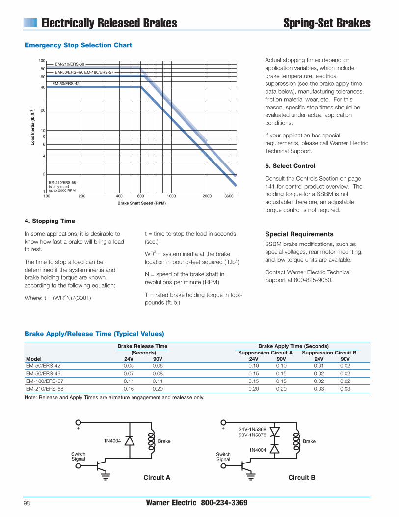
Electrically Released Brakes Spring-Set Brakes
98 Warner Electric 800-234-3369
Brake Apply/Release Time (Typical Values)
Brake Release Time Brake Apply Time (Seconds)(Seconds) Suppression Circuit A Suppression Circuit B
Model 24V 90V 24V 90V 24V 90VEM-50/ERS-42 0.05 0.06 0.10 0.10 0.01 0.02
EM-50/ERS-49 0.07 0.08 0.15 0.15 0.02 0.02
EM-180/ERS-57 0.11 0.11 0.15 0.15 0.02 0.02
EM-210/ERS-68 0.16 0.20 0.20 0.20 0.03 0.03
Note: Release and Apply Times are armature engagement and realease only.
Emergency Stop Selection Chart
4. Stopping Time
In some applications, it is desirable toknow how fast a brake will bring a loadto rest.
The time to stop a load can bedetermined if the system inertia andbrake holding torque are known,according to the following equation:
Where: t = (WR2N) /(308T)
t = time to stop the load in seconds(sec.)
WR2 = system inertia at the brakelocation in pound-feet squared (ft.lb2 )
N = speed of the brake shaft inrevolutions per minute (RPM)
T = rated brake holding torque in foot-pounds (ft.lb.)
Actual stopping times depend onapplication variables, which includebrake temperature, electricalsuppression (see the brake apply timedata below), manufacturing tolerances,friction material wear, etc. For thisreason, specific stop times should beevaluated under actual applicationconditions.
If your application has specialrequirements, please call Warner ElectricTechnical Support.
5. Select Control
Consult the Controls Section on page141 for control product overview. Theholding torque for a SSBM is notadjustable: therefore, an adjustabletorque control is not required.
Special Requirements
SSBM brake modifications, such asspecial voltages, rear motor mounting,and low torque units are available.
Contact Warner Electric TechnicalSupport at 800-825-9050.
ERS Series Circuits11/14/99page 138
Brake
Circuit A
1N4004
SwitchSignal
Brake
Circuit B
1N4004SwitchSignal
24V-1N536890V-1N5378
+ +
1100
Brake Shaft Speed (RPM)
Lo
ad In
erti
a (l
b.f
t.2 )
200 400 600 1000 2000 3600
2
4
6
8
10
20
40
60
80
100EM-210/ERS-68
EM-50/ERS-49, EM-180/ERS-57
EM-50/ERS-42
EM-210/ERS-68is only ratedup to 2000 RPM

All dimensions are nominal, unless otherwise noted.
A C E HModel Max B Max D Max F G Dia Key
(4) 3/8-16EM-50 5.232 3.125 .475 .937 .156 UNC 6.688 .625 3/16x3/16
on 5.875 Dia
(4) 3/8-16EM-180 5.292 3.125 .475 .937 .156 UNC 6.688 .875 3/16x3/16
on 5.875 Dia
(4) 1/2-13EM-210 7.579 4.609 .562 1.500 .315 UNC 9.344 1.125 1/4x1/4
on 7.250 Dia
Spring-Set Brakes Electrically Released Brakes
Warner Electric 800-234-3369 99
SSBM Series-EM/ERS
Model J K L M N P R S T U
4.500 .625EM-50 2.212 3/16x3/16 1.437 30° 36 45° 3.25 2.188
Pilot Dia Dia
4.500 .875EM-180 2.216 3/16x3/16 1.437 30° 36 45° 3.25 2.188
Pilot Dia Dia
8.500 1.125EM-210 3.002 1/4x1/4 2.125 25° 36 45° 3.25 2.188
Pilot Dia Diza

Electrically Released Brakes ERD Series Dynamic Braking With Reliable,Fast Response
100 Warner Electric 800-234-3369
The Warner Electric line of electricallyreleased, dynamic, spring-set brakes(ERD) offers a high-performance, costeffective solution for power-off loadholding applications.
These brakes are designed to safelykeep the load in position in the eventof a power or motor failure, whetherintentional or accidental. Anoptional manual release allowsthe operator to safely move theload even when no power isavailable.
By applying voltage to the ERD,an electromagnetic field iscreated which causes thearmature plate to pull-in againsthelical compression springs,thus releasing the brake.When power is removed,the springs force thearmature to compress thefriction carrier against themounting flange, thus stoppingand holding the load. Fullydynamic friction material on thecarrier allows for repeated brakingcycles from full motor speed with notorque fade.
Features
• Spring-set design holds the load inplace when voltage is removed from thebrake. Dynamic friction material can stoploads from motor speeds up to 3600 RPM.
• Few moving parts mean quiet operation
• Lead and asbestos free, dynamic frictionmaterial is suited for high cycle rates.
• Adjustable air gap for ease of service and long life in the field.
• Variety of voltages available.
• Simple DC control (or AC with availablerectifiers).
• Low power requirements for energysavings.
• Eight different sizes ranging from 3.3 inches to 9.9 inches in diameter.
• Torque capacities from 4 to 220 lb.ft.
• Bi-directional stopping capability.
Options
Manual ReleaseAllows the brake to be released by hand;ideal for lowering suspended loads.
Dust CoverShields the brake actuation system fromexternal dust and debris.
Splined Center HubSteel for wear resistance and
available in a variety of boresizes and keyways.
Compression SpringsUsed to provide balanced
armature plate loading.
Mounting FlangeEasily modified to suit unique bolt
patterns. In special cases, brakes maybe mounted directly to the motor
without the need for the flange.
Air GapFactory pre-set and easy to adjust
during field maintenance.
Continuous Duty CoilEpoxy-sealed; windings have ClassF insulation. Lead wires have stan-
dard Class B insulation rating.
Friction CarrierDouble friction surfaces for increased
torque in small package size.
Central Torque Adjustment(optional) Allows braking torque
adjustment down to 50% ofnominal rating; ideal for
controlling stopping distances.

ERD Series Electrically Released BrakesSelection
Warner Electric 800-234-3369 101
VAR 2Central ring nutadjusts torque• Up to 50%
torque reductionpossible
• Available in allsizes
Design VariationsTorque AdjustmentBrakes are factory set at the minimumtorque rating shown in theSpecifications chart.
Friction Disc CarriersReplaceable Friction carriers areavailable in two types:
• Metallic Standard on all brakes
• Thermoplastic can be used as anoption on sizes 5 and 10 brakes only
VAR 0Torque preset andconstant• No torque
adjustmentspossible
• Available in allsizes
VAR 1Four screw torqueadjustment • Up to 50% torque
reductionpossible
• Available in sizes5, 10, 20 and 35only
VAR 3Four screw torqueadjustment withprovision for tachometer
• Up to 50%torque reductionpossible
• Mounting holesfor tachometer
• Available in sizes5, 10, 20 and 35only
ERD Design Variations11/15/99page 145
Specifications
Holding Torque Max. Speed Rotating Inertia (lb. in.2) Current Draw (Amps) Resistance (Ohms) WeightSize lb. in. lb. ft. RPM Thermoplastic Metallic Disc 24 96 190 215 24 96 190 215 (lbs.)
ERD-5 45 3.75 3600 0.041 0.103 0.83 0.21 0.11 0.09 28.9 454 1775 2380 2
ERD-10 85 7.08 3600 0.137 0.321 1.03 0.26 0.13 0.12 23.4 372 1450 1813 4
ERD-20 175 14.58 3600 0.957 1.22 0.31 0.16 0.14 19.6 310 1209 1545 7
ERD-35 310 25.83 3600 2.529 1.61 0.41 0.21 0.18 14.9 233 912 1175 10
ERD-60 530 44.17 3000 7.415 1.94 0.577 0.293 12.4 166.2 648.1 14
ERD-100 890 74.17 3000 12.472 2.35 0.569 0.302 10.22 168.6 628.5 22
ERD-170 1500 125.00 3000 14.010 2.73 0.69 0.375 8.78 139.2 507.2 34
ERD-300 2650 220.83 3000 29.386 4.11 1.122 0.602 5.83 85.63 315.6 57
ERD Design Variations11/15/99page 145
ERD Design Variations11/15/99page 145
ERD Design Variations11/15/99page 145
Note: VAR 2 and VAR 0 are most common.

Electrically Released Brakes ERD Series Selection
102 Warner Electric 800-234-3369
ERD-5
ERD-10
ERD-20
ERD-35
ERD-60
ERD-100 ERD-170
ERD-300
1 10 100 1,000
1,000,000
100,000
10,000
1,000
100
Cycles per Hour
Fri
ctio
n W
ork
in J
ou
les
0 100 500 1000 1500 2000 2500 3000 3500
30
22.5
15
7.5
0
RPM
To
rqu
e in
lb
.ft.
ERD-5
ERD-10
ERD-20
ERD-35
0 100 500 1000 1500 2000 2500 3000
220
185
150
110
75
37
RPM
To
rqu
e in
lb
.ft.
ERD-60
ERD-170
ERD-300
ERD-100
Note: To convert Joules/min. to ft.lbs./min, multiply times .7376
Dynamic Torque
Energy Capacity
( )2
Proper ERD brake selection involvesdetermining,in order:
1. Static Holding TorqueThe ERD brake nominal holdingtorque should exceed the torque fromthe load by a minimum safety factorof 2.0
2. Dynamic TorqueThis is determined from the equation:
5250 PT = N
where:T = Dynamic Torque in lb.ft.N = Motor Speed in RPMP = Motor Horsepower
Once the dynamic torque has beencalculated, check the dynamic torquecurves (adjacent) at the requiredoperating speed to determine thesuitable brake.
3. Energy CapacityERD sizing by energy capacity is afunction of the cycling frequency(cycles per hour) and the single cycleenergy put into the brake asdetermined from the equation:
NE = 1.7 x WR2
100
where:E = Single Cycle Energy in lb.ft.WR2 = Load Inertia in lb.ft2
N = Speed in RPM
Applying the energy per cycle with thecycle rate to the energy curve, thebrake selection is verified.

ERD Series Electrically Released BrakesOrdering Information
Warner Electric 800-234-3369 103
0.721.58
0.951.07
1.82
ERD Connections11/15/99page 147
ERD Assembled Unit Dim11/15/99page 147
ThickFriction Plate
ManualRelease
DustCover
ElectricalConnection
Fully Assembled Unit
Connections
Rectifiers
AC Input DC Output Rectifier Part No.
240/220 V 96 V Half Wave ACG830A1P1
415/380 V 190 V Half Wave ACG830A1P1
240/220 V 190 V Full Wave ACG830A1P2
110 V 96 V Full Wave ACG830A1P2
Max. current = 1 AMP CG830 A1P1= 2 AMP CG830 A1P2
How to Order
Specify
1. ERD Series
2. Size: 5, 10, 20, 35, 60, 100, 170, or 300
3. Variation
0 – No torque adjustment1 – With torque adjusting screws2 – With central torque adjusting ring3 – With mounting holes for tachometer
4. Voltage
24 DC is standard
12, 96, 190, and 215 DCare modifications
5. Friction Carrier
Metallic carrier is standard
Thermoplastic carrier is available on sizes 5 and 10
6. Bore Size
ERD-5: 1/2" maxERD-10: 5/8" maxERD-20: 1" maxERD-35: 1-1/8" maxERD-60: 1-1/4" maxERD-100: 1-3/8" maxERD-170: 1-3/4" maxERD-300: 1-3/4" max
7. Mounting Flange
Thick Flange is standard
Thin Flange available up to size 35
8. Mounting Screws
Short Kit is standardLong Kit is available
9. Options
Dust Cover
Manual Release
Mounting Options
Flange Type Screw Kit Mounting Style
Thick Short Standard – Customer Mounting via Hole Pattern H
Thin Long Customer Mounting via Hole Pattern E
None Long Customer Mounting via Hole Pattern E
Typical brake unit (VAR 2) with options installed

Electrically Released Brakes ERD Series Dimensions–Brake Units
104 Warner Electric 800-234-3369
ERD Brake Unit Dim11/15/99page 148
L
KU
MND
E
A
S
YW
Z
VAR 1VAR 2 VAR 0 VAR 3
ERD Size A D Max. E K L Max. M +0.000/-0.008 N
5 3.307 0.5 2.835 1.378 1.575 0.709 0.071
10 4.016 0.625 3.543 1.614 1.831 0.787 0.098
20 5.000 1 4.409 1.870 2.165 0.787 0.138
35 5.787 1.125 5.197 2.146 2.559 0.984 0.118
60 6.378 1.25 5.709 2.520 2.933 1.181 0.118
100 7.402 1.375 6.693 2.795 3.209 1.181 0.118
170 8.465 1.75 7.717 3.268 3.780 1.378 0.177
300 9.921 1.75 9.055 3.819 4.528 1.575 0.197
ERD Size S U +/-0.002 W Y Z Bolt Pattern Variations Available
5 0.748 0.006 0.925 1.299 4xM4 0, 1, 2, 3
10 0.945 0.006 1.122 1.594 4xM5 0, 1, 2, 3
20 1.378 0.008 1.594 2.224 4xM5 0, 1, 2, 3
35 1.575 0.008 1.909 2.244 4xM5 0, 1, 2, 3
60 1.890 0.012 2.303 0, 2
100 2.047 0.012 2.500 0, 2
170 2.362 0.012 2.894 0, 2
300 2.874 0.012 3.484 0, 2
For service information, request manual P-229.

ERD Series Electrically Released BrakesDimensions–Accessories
Warner Electric 800-234-3369 105
ERD Friction Options11/15/99page 149
AA
BB
CC
DD
EE
Release Angle
ERD Friction Plate Dim11/15/99page 149
B
H
P
EC
h
J
e
f
E
FG
0.06
f
Friction Plates
f he Bolt Bolt
Bolt Clearance ClearanceERD Size B C E Pattern Holes F G H Holes J P
5 3.268 0.787 2.835 3xM4 3x0.177 1.654 3.425 1.181 3x0.177 0.079 0.236
10 3.937 1.181 3.543 3xM5 3x0.217 2.126 4.213 1.772 3x0.217 0.079 0.276
20 4.921 1.575 4.409 3xM6 3x0.256 2.362 5.217 2.205 3x0.256 0.118 0.354
35 5.709 1.772 5.197 3xM6 3x0.256 2.953 6.004 2.441 3x0.256 0.118 0.354
60 6.299 2.165 5.709 3xM8 3x0.335 3.346 6.732 2.913 3x0.335 0.118 0.433
100 7.283 2.559 6.693 3xM8 3x0.335 3.858 7.717 3.307 3x0.335 0.118 0.433
170 8.346 2.953 7.717 6xM8 6x0.335 3.937 6x0.335 0.118 0.433
300 9.843 3.543 9.055 6xM10 6x0.413 4.724 6x0.413 0.118 0.433
ERD Size AA BB CC DD EE Release Angle
5 3.86 2.09 0.67 3.46 3.46 10
10 4.21 2.44 0.71 4.17 4.17 8
20 5.08 2.99 0.98 5.20 5.20 7
35 5.47 3.39 0.87 5.98 5.98 7
60 6.75 4.09 1.61 6.06 6.54 7
100 7.74 4.72 1.73 7.01 7.36 7
170 9.57 5.51 2.09 7.99 8.78 10
300 12.44 6.38 2.36 9.33 10.33 10
Thin Friction Plate (Sizes 5 thru 35 only)
The thick mounting flange provides the proper material and mounting tolerances for thebrake. The thin mounting flange provides the proper material in applications where flatness,squareness and concentricity requirements are met on the machine already.
Dust Cover
Manual Release
Thick Friction Plate (Standard – all sizes)

Electrically Released Brakes Permanent MagnetPermanent Magnet Brakes
106 Warner Electric 800-234-3369
Packaged Convenience for Power Off Applications
FB Brake ondouble shaft motor.
FB Series permanent magnet brakes areoffered as off-the-shelf, pre-assembledpackages in three sizes. Packagedproducts are easy to install.
ER Series permanent magnet brakes allowcustomers added flexibility and largersizes. 825 and 1225 are available in bothstandard and heavy duty models.
Principle of OperationElectrically Released Brakes automaticallyengage when the power goes off. Reliablepermanent magnets provide a permanentholding force. Electrical power applied tothe coil nullifies the attraction of thepermanent magnet and the brake releases.No power is required to stop or hold a load.
Frequent cycling applications whichregularly engage the brake to stop amoving load call for FB or ER models.Frequent cycling keeps working surfacesburnished and operating at top efficiency.The convenience of power off brakingcombines with stopping capability in theevent of power failure to provide the idealbrake for many applications.
FB Series (Shaft Mounted)
ER Series (Flange Mounted)
Features
• Designed for dynamic stoppingoperations
• Brake automatically engages whenpower is turned off
• High cycle rate capability
• Never needs adjustment – automaticallycompensates for wear
• Mounting flexibility
• Powerful permanent magnets
• Segmented armature design provideshigh heat dissipation and long service life.
• Complete controllability for soft stops.
• UL, CSA listed
FB Magnetically Set,Electrically Released,Dynamic Engagement Brake
Packaged brake assembly complete withconduit box is ready to install.
This brake must be engaged while theshaft is in motion. Shaft speed should be100 RPM or greater when the brake isengaged. This style brake offers quick andeasy bearing mounting on the shaft, highcycle rate capability, and excellent life.
Long Life – High Cycle RatesSegmented armature provides high
heat dissipation and long service life. Capable of rapid cycling.
Mounting FlexibilityThe FB torque arm feature
permits mounting on any shaft.Wide range of shaft sizes.
High Torque Powerful permanent magnets.
Autogap®
Automatic wear adjust.
Electrically ReleasedBrake automatically
engages when power isturned off– releases
when power is applied.

FB Series Electrically Released BrakesSelection/Ordering Information
Warner Electric 800-234-3369 107
Storage ElevatorThese brakes will stop as well as keepa load in position until they areelectrically released. They are alsoused as emergency stopping devices.
FB HP/Shaft Speed Chart11/15/99page 156
1/12
1/8
1/6
1/4
1/3
1/2
3/4
1
1-1/2
HP SHAFT SPEED AT BRAKE (IN RPM)
Horsepower vs. Shaft Speed
100 200 300 400 500 600 700 800 900 1000 1100 1200 1500 1800 2000 2400 3000 3600 4000 4500
2
3
5
7-1/2
10
15
FB-375
FB-475
FB-650
Selection ProcedureFB (Shaft Mounted) Series brakes areavailable in three models to provide anoptimum size to match your applicationrequirements. Static torque capabilitiesrange from 10.5 lb.ft. to 56 lb.ft.
1. Verify that the brake will be cycledfrequently in normal operation.
2. Determine the horsepower and speedat the brake location.
3. The correct size Electrically ReleasedBrake is shown at the intersection ofthe HP and shaft speed on the chartbelow.
4. Available bore sizes are listed in thebore data chart. When ordering, specifyvoltage and bore size.
5. Five motor adapters are also availablefor mounting Electrically ReleasedBrakes on single shaft extensionmotors (see motor adapter bore sizechart on page 108). For double shaftextension motors, the adapter can beeliminated. Specify motor shaft size.
* For applications which require stopping below 100 RPM, consult factory.
How to Order1. Specify brake part number.
2. For FB-475 and FB-650, order bushingseparately. FB-375 does not require abushing.
3. For single shaft motor mounting, orderadapter separately (Item 2 below).Specify the following bore size for theFB brake. This is the bore size requiredfor mounting the electrically releasedbrake on the end of the motor adapter.
FB-375 5/8" bore
FB-475 1-1/8" bore
FB-650 1-3/8" bore
4. See the Controls Section for controls.FB Series brakes require a control witha potentiometer to vary brake channeloutput.
CBC-200, 300 or 500/550 arerecommended.
Electrically Released Brake Assemblies
Unit Size Bore Voltage DC Part NumberFB-375 1/2" 24 5390-170-024FB-375 1/2" 90 5390-170-021FB-375 5/8" 24 5390-170-023FB-375 5/8" 90 5390-170-022
FB-475 — 24 5391-170-012FB-475 — 90 5391-170-009
FB-650 — 24 5392-170-010FB-650 — 90 5392-170-007
Horsepower vs. Shaft Speed*
*
Specifications
StaticModel Voltage DC Torque (lb.ft.) Max. RPM Total Weight (lbs.)
FB-37524V
10.5 5000 4.590V
FB-47524V
21 4500 6.390V
FB-65024V
56 3600 13.290V
Typical Application

Electrically Released Brakes Permanent MagnetMotor and Shaft Adapaters
108 Warner Electric 800-234-3369
Motor A When using an adapterModel Shaft Usable B order the followingSize Size Length Dia. Adapter Dodge Bushing
375.625 2.000 .875 5380-101-005 *None.875 2.250 1.250 5380-101-004 *None
475 1.125 2.750 1.625 5381-101-003 #1008 1”
6501.375 3.000 2.000 5382-101-003 #1310 1.375”1.625 3.625 2.250 5382-101-002 #1310 1.375”
*Order FB-375 with 5/8” bore.
FB Motor Bore Sizes11/15/99page 157
B
MotorAdapter
A
FB Shaft AdapterShown below are dimensions andspecifications for the optional shaft adapteravailable for mounting FB Series brakes ona motor. A standard sheave, pulley, orsprocket, with either a tapered bushing orstraight bore, can be installed on the shaftadapter. The brake is mounted on the endof the shaft adapter and the completeassembly fits onto the motor shaft, securedwith setscrews. Fitting the belts or chainand torque arm completes the installation.
DodgeKey Key Bushing
Model A Kwy. B Kwy. Part No. C Kwy. Part No. Size D E F G H I
FB-375 5/83/16 x
7/83/16 x
590-0016 5/83/16 x
590-0043 None4.391
2.391
21/4-20
1.1253/32 3/32 3/32 4.359 .359 UNC
FB-375 7/83/16 x
1-1/41/4 x
590-0022 5/83/16 x
590-0043 None4.578
2-1/4.516
2-1/41/4-20
1.5003/32 1/8 3/32 4.742 .484 UNC
FB-475 1-1/81/4 x
1-5/83/8 x
590-0041 11/4 x
—#1008 4.516
2-3/4.641
2-3/41/2-13
1.7501/8 3/16 1/8 1" 4.484 .609 UNC
FB-650 1-3/85/16 x
21/2 x
590-0042 1-3/85/16 x
590-0044#1310 5.547
3-3/8.641
3-3/81/2-13
2.1255/32 1/4 5/32 1-3/8" 5.515 .609 UNC
FB-650 1-5/83/8 x
2-1/41/2 x
590-0042 1-3/85/16 x
590-0044#1310 6.172
4.641
41/2-13
2.3753/16 1/4 5/32 1-3/8" 6.140 .609 UNC
All dimensions are nominal unless otherwise noted.
Motor Adapter Bore Sizes
FB Shaft Adapter11/15/99page 157
D
E
B C
G
A I
F
H(Threaded
Removal Hole)

FB Series Electrically Released BrakesFB-375, FB-475, FB-650
Warner Electric 800-234-3369 109
FB-375, 475, 650 Dim11/15/99page 158
R
U
V
T
FF
DD
CC
EEGG
BB
AA
LK
W
J
H
GA B C D
E
F
Q
OP
NM S
All dimensions are nominal, unless otherwise noted
A B C D E G MSize Max. Dia Min. Dia. Min. F Dia. H J K L Max. N O P
375 4.078 3.125 .7505 — .031 1.906 1.375 3.359 .187 1.281 1.546 2.716 .843 .281 .531
475 5.171 4.000 1.663 1.593 — 1.875 1.781 3.875 — 1.218 1.546 3.390 1.093 .312 .531
650 6.578 5.125 2.343 2.281 — 2.250 2.562 4.800 — 1.550 1.546 3.765 1.031 .343 .640
Q S AASize Max. R Dia. T U V W Max. BB CC DD EE FF GG
375 — 2.000 1.500 .270.270
.781 .359 4.468 3.750 1.000 8.000 .666 .635 2.578.260
475 .281 2.000 1.500 .270.270
.781 .390 4.984 3.750 1.000 10.000 .697 .635 3.094.260
650 .359 2.000 1.500 .270.270
.781 .437 5.843 3.750 1.125 11.000 .843 .635 4.062.260
Bore Data (Key furnished)
Size Bore Dia. Keyway
FB-375.626/.625 3/16 x 3/32.501/.500 1/8 x 1/16
FB-475.500 – .562 1/8 x 1/16
Dodge #1008.625 – .875 3/16 x 3/32.937 – 1.000 1/4 x 1/8
.500 – .562 1/8 x 1/16FB-650 .625 – .875 3/16 x 3/32Dodge #1310 .937 – 1.250 1/4 x 1/8
1.312 – 1.375 5/16 x 5/32
Note: FB-375 has a straight bore. Bushing not required.Bushings also available in metric bores.

Electrically Released Brakes ER SeriesIdeal for Dynamic Braking Applications
110 Warner Electric 800-234-3369
ER HP/Shaft Speed Chart11/15/99page 160
1/12
1/8
1/6
1/4
1/3
1/2
3/4
1
1-1/2
HP SHAFT SPEED AT BRAKE (IN RPM)
Horsepower vs. Shaft Speed
100 200 300 400 500 600 700 800 900 1000 1100 1200 1500 1800 2000 2400 3000 3600 4000 4500
2
3
5
7-1/2
10
15
20
25
30
40
50
60
75
ER-375
ER-475
ER-650
ER-825
ER-1225
Flange Mounted Brakes
Horsepower vs. Shaft Speed
Powerful permanent magnets.
Never needs adjustment–automatically compensates for wear.
Brake automatically engageswhen power is turned off.
Pre-burnished to assure ratedtorque upon installation.
Segmented armature designprovides high heat dissipation
and long service life.
ER SeriesDynamic Engagement BrakesThis brake must be engaged while theshaft is in motion. Shaft speed should be100 RPM or greater when the brake isengaged. This style brake offers abulkhead flange mounting system, thehighest torque rating offered by WarnerElectric in the power released series, highcycle rate capability, and excellent life.
• Expands the electrically releasedproduct family with two larger sizes
• Designed for dynamic stoppingoperations
• High cycle rate capability
• Inside or outside mount options for 475or 650 sizes
• Normal or heavy duty options availablein larger sizes
Selection ProcedureER Series brakes are available in five sizes.Static torque ratings range from 10.5 lb.ft.to 400 lb.ft.
1. Verify that the brake will be cycledfrequently in normal operation.
2. Determine the horsepower and speedat the brake location.
3. The correct size ER Series brake isshown at the intersection of the HPand shaft speed.
4. When ordering, specify voltage andbore size. Available bore sizes arelisted in the specifications chart.
How to Order1. Specify model number
2. For thru-shaft mounting, specify boresize. For ER-475 and ER-650 orderbushing separately, ER-375 does notrequire a bushing.
3. Models ER-475 and ER-650: Specifyinside or outside mount. Models ER-825 and ER-1225: Specify normal orheavy duty.
4. See the Controls Section for controls.ER Series brakes require a controlwith a potentiometer to vary brakechannel output; CBC-200, 300 or500.550 (ER-825 only) or MCS-805-1 or -2 (ER-1225 only)are recommended.

Warner Electric 800-234-3369 111
ER Series Electrically Released Brakes
Bushing Part NumbersBushing Number
Shaft Keyway Warner Size Size Electric Browning1/2 1/8 x 1/16 180-00029/16 1/8 x 1/16 180-00035/8 3/16 x 3/32 180-000411/16 3/16 x 3/32 180-00053/4 3/16 x 3/32 180-000613/16 3/16 x 3/32 180-00077/8 3/16 x 3/32 180-000815/16 1/4 x 1/8 180-0009 H-11 1/4 x 1/8 180-00101-1/16 1/4 x 1/8 180-00111-1/8 1/4 x 1/8 180-00121-3/16 1/4 x 1/8 180-00131-1/4 1/4 x 1/8 180-00141-5/16 5/16 x 5/32 180-00151-3/8 5/16 x 5/32 180-0016
1-7/16 3/8 x 3/16 180-0017 H-21-1/2 3/8 x 3/16 180-0018
3/4 3/16 x 3/32 180-002613/16 3/16 x 3/32 180-00277/8 3/16 x 3/32 180-002815/16 1/4 x 1/8 180-00291 1/4 x 1/8 180-00301-1/16 1/4 x 1/8 180-00311-1/8 1/4 x 1/8 180-00321-3/16 1/4 x 1/8 180-00331-1/4 1/4 x 1/8 180-00341-5/16 5/16 x 5/32 180-0035 QI-11-3/8 5/16 x 5/32 180-00361-7/16 3/8 x 3/16 180-00371-1/2 3/8 x 3/16 180-00381-9/16 3/8 x 3/16 180-00391-5/8 3/8 x 3/16 180-00401-11/16 3/8 x 3/16 180-00411-3/4 3/8 x 3/16 180-00421-13/16 1/2 x 1/4 180-00431-7/8 1/2 x 1/4 180-00441-15/16 1/2 x 1/4 180-0045
2 1/2 x 1/4 180-00462-1/16 1/2 x 1/4 180-00472-1/8 1/2 x 1/4 180-0048 QI-22-3/16 1/2 x 1/4 180-00492-1/4 1/2 x 1/4 180-0050
Browning® is registered to Emerson Electric Co.Dodge and Browning bushings are also availablein metric bores.
Bushing NumberShaft Keyway Warner Size Size Electric Browning2-5/16 5/8 x 5/16 180-00512-3/8 5/8 x 5/16 180-00522-7/16 5/8 x 5/16 180-00532-1/2 5/8 x 5/16 180-0054 QI-22-9/16 5/8 x 5/16 180-00552-5/8 5/8 x 5/16 180-00562-11/16 5/8 x 5/16 180-0057
1/2 1/8 x 1/16 180-01319/16 1/8 x 1/16 180-01325/8 3/16 x 3/32 180-013311/16 3/16 x 3/32 180-01343/4 3/16 x 3/32 180-013513/16 3/16 x 3/32 180-01367/8 3/16 x 3/32 180-013715/16 1/4 x 1/8 180-01381 1/4 x 1/8 180-01391-1/16 1/4 x 1/8 180-0140 16151-1/8 1/4 x 1/8 180-01411-3/16 1/4 x 1/8 180-01421-1/4 1/4 x 1/8 180-01431-5/16 5/16 x 5/32 180-01441-3/8 5/16 x 5/32 180-01451-7/16 3/8 x 3/16 180-01461-1/2 3/8 x 3/16 180-01471-9/16 3/8 x 3/16 180-01481-5/8 3/8 x 3/16 180-0149
15/16 1/4 x 1/8 180-02621 1/4 x 1/8 180-02631-1/16 1/4 x 1/8 180-02641-1/8 1/4 x 1/8 180-02651-3/16 1/4 x 1/8 180-02661-1/4 1/4 x 1/8 180-02671-5/16 5/16 x 5/32 180-02681-3/8 5/16 x 5/32 180-0269 30301-7/16 3/8 x 3/16 180-02701-1/2 3/8 x 3/16 180-02711-9/16 3/8 x 3/16 180-02721-5/8 3/8 x 3/16 180-02731-11/16 3/8 x 3/16 180-02741-3/4 3/8 x 3/16 180-02751-13/16 1/2 x 1/4 180-02761-7/8 1/2 x 1/4 180-0277
Bushing NumberShaft Keyway Warner Size Size Electric Browning1-15/16 1/2 x 1/4 180-02782 1/2 x 1/4 180-02792-1/16 1/2 x 1/4 180-02802-1/8 1/2 x 1/4 180-02812-3/16 1/2 x 1/4 180-02822-1/4 1/2 x 1/4 180-02832-5/16 5/8 x 5/16 180-02842-3/8 5/8 x 5/16 180-02852-7/16 5/8 x 5/16 180-0286 30302-1/2 5/8 x 5/16 180-02872-9/16 5/8 x 5/16 180-02882-5/8 5/8 x 5/16 180-02892-11/16 5/8 x 5/16 180-02902-3/4 5/8 x 5/16 180-02912-13/16 3/4 x 3/8 180-02922-7/8 3/4 x 3/8 180-02932-15/16 3/4 x 3/8 180-02943 3/4 x 3/8 180-0295
1/2 1/8 x 1/16 180-04109/16 1/8 x 1/16 180-04115/8 3/16 x 3/32 180-041211/16 3/16 x 3/32 180-04133/4 3/16 x 3/32 180-0414 100813/16 3/16 x 3/32 180-04157/8 3/16 x 3/32 180-041615/16 1/4 x 1/16 180-04171 1/4 x 1/16 180-0418
1/2 1/8 x 1/16 180-04219/16 1/8 x 1/16 180-04225/8 3/16 x 3/32 180-042311/16 3/16 x 3/32 180-04243/4 3/16 x 3/32 180-042513/16 3/16 x 3/32 180-04267/8 3/16 x 3/32 180-042715/16 1/4 x 1/16 180-0428 13101 1/4 x 1/8 180-04291-1/16 1/4 x 1/8 180-04301-1/8 1/4 x 1/8 180-04311-3/16 1/4 x 1/8 180-04321-1/4 1/4 x 1/8 180-04331-5/16 15/16 x 5/32 180-04341-3/8 15/16 x 5/32 180-0435
Specifications
Inertia lb.ft.2 Weight lbs. TotalModel Bore Size Voltage DC Static Torque lb. ft. Max. RPM Drive Arm. & Carrier Hub Arm. & Carrier Hub Weight lbs.ER-375 .500" & .625" 90V 10.5 5000 – .010 .001 .60 .49 4.5
ER-475.500" to 1.000"
90V 21 4500 – .072 .006 1.13 6.3Dodge #1008
ER-650.500" to 1.375"
90V 56 3600 – .106 .020 2.3 1.6 13.2Dodge #1310
ER-825 .500" to 1.625"90V 125 3600
Pin .323 .043 4.783 1.857ND Dodge #1615 Spline .326 .006 5.263 .834
15.6
ER-825 .500" to 1.500"90V 125 3600
Pin .323 .043 4.783 1.857 15.6HD Browning #H-1 Spline .326 .006 5.263 .834
ER-1225 .937" to 3.00"35-75V 400 3000
Pin 1.667 .380 10.227 6.71660.3ND Dodge #3030 Spline 1.737 .077 13.317 3.582
ER-1225 .75" to 2.687"35-75V 400 3000
Pin 1.667 .380 10.227 6.71660.3HD Browning #Q-1 Spline 1.737 .077 13.317 3.582

Electrically Released Brakes ER SeriesER-375, ER-475, ER-650
112 Warner Electric 800-234-3369
X dia. (Y) holesequally spacedon Z dia.
Mounting holesare within 0.010of true position relative topilot diameter.
T
P
Removable plug in ends for1/2" conduit
Q
R
U dia. (V) holesequally spaced on W dia.
S
AA Pilot
M*N**
LC
H
AB AC
K
J*
F
G**
For Bore & Keyway sizes see chart below
E
D
A
B*
**Inside MountingOutside Mounting
Mounting RequirementsCustomer Shall Maintain:1. Squareness of brake mounting face
with armature hub shaft within .006T.I.R.
2. Concentricity of brake mounting pilotdiameter with armature hub shaft within.010 T.I.R.
Bore and Keyway Dimensions
Size Bore Dia. Keyway
375.501/.500 1/8 x 1/16.626/.625 3/16 x 3/32
.500 - .562 1/8 x 1/16475 .625 - .875 3/16 x 3/32
.937 - 1.000 1/4 x 1/8
.500 - .562 1/8 x 1/16
650.625 - .875 3/16 x 3/32
1.000 - 1.250 1/4 x 1/81.312 - 1.375 5/16 x 5/32
All dimensions are nominal, unless otherwise noted.
Size A Max. B Max. C Max. D E F Max. G H Max. J K L M N P
375 4.078 2.583 2.583 .032 1.410 .6005/16-18
— — 3.325 1.547 — — 3.750UNC-3A
475 5.172 3.195 3.274 .031 1.630 .4313/8-16
.390 8-32 3.875 1.547 1.354 1.236 3.750UNC-3A
650 6.578 3.525 3.525 .032 1.880 .5425/16-18
.5425/16-18
4.800 1.547 — — 3.750UNC-3A UNC-3A
Size Q Max. R S T Sq. U V W Dia. X Y Z Dia. AA Dia. AB AC
375 4.505 —5.625
—.350
3 5.000 — — — — 23/32 1-3/45.623 .341
475 5.000 45°6.500
5.000.419
4 5.875.208
8 2.3752.065
29/321-3/16 I.M.
6.498 .403 .201 2.062 1-1/16 O.M.
650 5.844 45°8.000
6.500.358
4 7.250.358
4 3.6882.822
1-1/32 1-3/87.998 .338 .338 2.820
3. If magnet mounting surface is amagnetic material, the magnet isto be insulated approximately 1/2" fromthat surface with a plate or spacers ofnon-magnetic material.
ER-375 available outside mounted only.

Warner Electric 800-234-3369 113
ER Series Electrically Released BrakesER-825, ER-1225
Removableplug in endsfor 1/2" conduit
Mounting holes are within 0.005 of true position relative to pilot diameter
VPilot Dia.
K
J
K
J
G
H
GI
H
S dia. (T) holesequally spaced on U dia.
DEC
AB
AB
D
E
PON
M
PON
L
R
Q
I
Mounting RequirementsCustomer Shall Maintain:1. Squareness of magnet mounting face
with armature shaft within .006 T.I.R.
2. Concentricity of magnet mountingpilot diameter with armature shaftwithin .010 T.I.R.
ER-825 and ER-1225Normal Duty (N.D.)
ER-825 and ER-1225Heavy Duty (H.D.)
ER-825 & ER-1225 Magnet View(Same for Pin Drive and Spline Drive)
3. If magnet mounting surface is a magnetic material, the magnet isto be insulated approximately 1/2"from that surface with a plate orspacers of non-magnetic material.
M N O P Q R S T U VSize When New Max. Max.
825 N.D. .093 .5622.080
4.359 3.7506.750
.358 6 4.250 3.503.338 3.501
825 H.D. — .5312.080
3.546 3.7506.750
.358 6 4.250 3.503.338 3.501
1225 N.D. .156 .5932.500
6.218 3.7508.796
.358 6 7.250 6.378.338 6.376
1225 H.D. — .5622.500
5.031 3.7508.796
.358 6 7.250 6.378.338 6.376
A B C D E G H I J K LSize Max. Dia. Max. Min. Min.
825 N.D. 8.656 4.625 — 1.593 1.500 5.625 .5315/16-18
1.687 1.546 —UNC-3A
825 H.D. 8.656 2.500 .156 1.250 1.765 5.625 .5315/16-18
1.687 1.546 .062UNC-3A
1225 N.D. 12.671 6.875 — 3.000 3.000 7.671 .5465/16-18
1.718 1.546 —UNC-3A
1225 H.D. 12.671 4.093 .234 2.500 2.171 7.671 .5465/16-18
1.718 1.546 .062UNC-3A
Bore and Keyway Dimensions
ER-825 Bore Dia. KeywayPin .500 - .562 1/8 x 1/16Drive .625 - .875 3/16 x 3/32
.937 - 1.250 1/4 x 1/81.312 - 1.375 5/16 x 5/321.437 - 1.500 3/8 x 3/161.562 - 1.625* 3/8 x 3/16
Spline .500 - .562 1/8 x 1/16Drive .375 - .625 3/16 x 3/32
.937 - 1.187 1/4 x 1/81.250* 1/4 x 1/8
1.312- 1.375* 5/16 x 5/321.437 - 1.500* 3/8 x 3/16
ER-1225Pin .937 - 1.250 1/4 x 1/8Drive 1.312 - 1.375 5/16 x 5/32
1.437 - 1.750 3/8 x 3/161.812- 2.250 1/2 x 1/42.312 - 2.750 5/8 x 5/162.187 - 3.000* 3/4 x 3/8
Spline .750 - .875 3/16 x 3/32Drive .937- 1.250 1/4 x 1/8
1.312 - 1.375 5/16 x 5/321.437 - 1.750 3/8 x 3/161.812 - 2.062 1/2 x 1/42.125 - 2.250* 1/2 x 1/42.312 - 2.687 5/8 x 5/16
*Key furnished

Electrically Released Brakes Permanent Magnet ModulesFor Dynamic Stopping and Cycling Applications
114 Warner Electric 800-234-3369
EM/EUM-FBB Features11/15/99page 166
Warner Electric’s modular design brakes and clutch/brake unitsoffer material handling system users a high performancealternative to spring-set brakes. These modular units providelong life, maintenance free operation, and consistentperformance with minimal downtime.
These brakes are offered in power-off types for double shaftmotors and for installation between C-face motor and reducer orother drive device. Powerful permanent magnets generatebraking torque. The brakes release when voltage is applied tothe coil, countering the force of the permanent magnets. Nopower is required to stop or hold a load. An optional integralconduit box provides simple wiring direct from the motor powerleads.
• Designed for dynamic stopping operations
• Brake automatically engages when power is turned off
• High cycle rate capability
• Never needs adjustment – automatically compensates forwear
• Powerful permanent magnets provide braking force
• Choice of open or enclosed brakes
• Prepackaged, preburnished UM version
Three C-face Compatible DesignsThe UM Series (UniModule Clutch/Brakes) are preassembledclutch/electrically released brake modules.
• The UM-1020-FBC brake/motor clutch combination is usedfor clutch/power-off brake applications. It mounts directly toC-face compatible components.
• The UM-2030-FBC brake/input clutch combination is used forclutch/power-off brake applications. It has shafts on both theinput and output sides for base mounting.
The EUM Series (Enclosed Motor Brakes) are totally enclosednon-vented units that keep wear particles in and contaminantsout.
• The EUM-FBB brake unit can be mounted between two C-face compatible components.
• The EUM-MBFB motor brake is mounted directly to the rearof a double-shafted motor.
The EM Series (Electro Module Brakes and Clutch/Brakes)are comprised of individual units that may bolt together to formvarious combinations:
• The EM-FBB brake module mounts between a C-face motorand a gear box or reducer.
• The EM-MBFB motor brake module is mounted to the rear ofa double-shafted motor.
• The EM-FBC brake module is used in combination with amotor clutch or input clutch unit to make a cluch/electricallyreleased brake or can be used alone as a brake only.
Brake Modules (FBB) – For mounting between a C-face motor and a gearbox or reducer
EM Series Shaft mounted, vented housing
EUM Series Shaft mounted, totally enclosednon-vented housing
Use for brake alone applications.
Features• Single armature for brake
alone applications
• Output shaft
• Permanent magnets
• UL listed and CSA certified
EM-FBBAvailable in 4 sizes
EUM-FBBAvailable in 4 sizes
EM-FBB Electro Modulebrake unit between amotor and a reducer.

Warner Electric 800-234-3369 115
Permanent Magnet Modules Electrically Released BrakesC-face Compatible Brakes
and Clutch/BrakesEM/EUM-MBFB Features
EM Series vented housing
EUM Series totally enclosednon-ventedhousing
Use as a motor brake on C-face type motors.
Motor Brake Modules (MBFB) – For mounting directlyto the rear of a double-shafted motor
EM Series Modular unit withC/B capability
UM Series Fully assembled C/Bcombination package
Clutch/Brake Modules (FBC) – Clutch/Fail-safebrake for mounting between a C-face motor and agearbox or reducer
Combine with a motor or input clutch for clutch/brakeapplications or use alone as a brake only.
Typical mounting of anMBFB module on theback of a C-face motor
UM-FBC UniModuleclutch/brake mounted
on a base
EM-FBC Electro Modulebrake unit combined with amotor clutch module
Features• Single armature design
• Complete torque control
• Precision cast housing
• Ceramic type permanentmagnets
EM-MBFBAvailable in 4 sizes
EUM-MBFBAvailable in 5 sizes
Features• Dual armature for
clutch/brake combination
• Output shaft
• Can be base mounted foruse as a separate drive unit.
EM-FBCAvailable in 3 sizes
UM-FBCAvailable in 4 sizecombinations

Electrically Released Brakes UM-FBC SeriesUniModule Clutch/Electrically ReleasedBrake Combination
116 Warner Electric 800-234-3369
Warner Electric offers the convenience ofpre-assembled UniModuleclutch/electrically released brake packages.Assembly, alignment, and pre-burnishinghave been done at the factory. Bolt it on,wire it up, and your clutch/electricallyreleased brake is ready to go. Available inboth C-face and base mounted versions.
Fan cooled for long life andconsistent performance.
NEMA C-facecompatible design
Single conduit entrance
Heavy duty bearingsmaintain tightconcentricity andrunning efficiency.
High torque, long life,asbestos-free friction material
Completely sealed coils
Easy set screw access
Bearing mounted rotor.
Autogaps®
automatically adjust for wear.
Finned design for maximum
heat dissipation.
Warner Electric’s unique design employspowerful permanent magnets formaximum torque when power is removedfrom the brake coil. A small amount ofelectrical power applied to the brake coilnullifies the permanent magnets and thebrake releases. No springs to limit cyclerates. Never any adjustments. No
lubrication. These brakes arerecommended for dynamic cyclingoperations only.

Warner Electric 800-234-3369 117
UM-FBC Series Electrically Released Brakes
Frame Size Selection and Technical Ratings Chart
Static Torque Static TorqueNEMA UniModule Brake Clutch Max. Voltage
Frame Size Size lb.ft. lb. RPM DC
56C/48YUM-50* 10.5 16
3600 24 or 90UM-100** 21 30
182C/143TCUM-180 21 30 3600 24 or 90184C/145TC
213C/182TCUM-210 56 95 3600 24 or 90215C/184TC
213TC/215TC UM-215 56 95 3600 24 or 90
*For 56C/48Y C-frame motors 3/4 HP and smaller, the UM-100 size may be used where extended life is desirable.
**The UM-100 size is recommended for motors 1 HP and larger.
UM-FBC HP/Shaft Speed Chart11/15/99page 169
1/4
1/2
3/4
1
HP SHAFT SPEED AT CLUTCH (IN RPM)
Horsepower vs. Shaft Speed
100 200 300 400 500 600 700 800 900 1000 1100 1200 1500 1800 2000 2400 3000 3600
1-1/2
2
3
5
7-1/2
UM-50
UM-100 or UM-180
UM-210 or UM-215
Horsepower vs. Shaft Speed
Selection
UniModule clutch/electrically releasedbrake units may be mounted directly toNEMA C-face motors and reducers, orcan be base mounted.
Verify the unit will be cycled frequently.
To select the correct UniModulepackage, determine the NEMA framesize of your motor and/or reducer, andchoose the corresponding sizeUniModule from the Frame SizeSelection chart. Verify torque ratings.
1. Select Configuration
a. NEMA C-face Mounting(1020 Configuration)
b. Base Mounting (2030 Configuration)
Verify the unit will be cycled frequently.
Select the correct size module from theHorsepower vs. Shaft Speed chartbydetermining the motor horsepower andRPM at the module location. Thecorrect size UniModule is shown at theintersection of the HP and operatingspeed. For additional sizing information,refer to the technical sizing procedure(step 2).
2. Determine Technical Requirements
Technical considerations for sizing andselection are torque and heat dissipation.Each merits careful consideration,especially heat dissipation as over time,use in excessive temperatureenvironments will have an adverse effecton bearing life and coil wire insulationintegrity.
Compare the calculated torquerequirement with the average dynamictorque ratings. Select a unit with adequatetorque. If the unit selected on torque isdifferent than the unit selected based onheat, select the larger size unit.

Electrically Released Brakes UM-FBC Series
118 Warner Electric 800-234-3369
a. Heat Dissipation SizingFriction surfaces slip during the initialperiod of engagement and, as a result,heat is generated. The clutch/brakeselected must have a heat dissipationrating greater than the heat generatedby the application. Therefore, in highinertia or high cycle rate applications, itis necessary to check the heatdissipation carefully. Inertia, speed andcycle rate are the required parameters.
Heat dissipation requirement iscalculated as follows:
E = 1.7 x WR2 x (N/100)2 x F
where:
E = Heat (lb. ft./min.)
WR2 = Total reflected inertia at theclutch/brake shaft. Include theclutch/brake output inertia. (lb.ft.2 )
N = Speed in revolutions per minute.(RPM)
F = Cycle rate in cycles per minute(CPM)
Compare the calculated heat generatedin the application to the unit ratingsusing the heat dissipation curves. Selectthe appropriate unit that has adequateheat dissipation ability.
0
6000
12000
18000
24000
30000
36000
0 3600900 1800 2700
Speed (RPM)
Hea
t D
issi
pat
ion
(ft.
lbs.
/min
.)
Size 210/215Maximum Speed 3600 RPM
250° F
200° F
0
3000
6000
9000
12000
15000
18000
0 3600900 1800 2700
Speed (RPM)
Hea
t D
issi
pat
ion
(ft.
lbs.
/min
.)
Size 100/180Maximum Speed 3600 RPM
250° F
200° F
0 36000
4000
8000
12000
2000
6000
10000
900 1800 2700
Speed (RPM)
Hea
t D
issi
pat
ion
(ft.
lbs.
/min
.)
Size 50Maximum Speed 3600 RPM
200° F
250° F
Heat Dissipation Curves
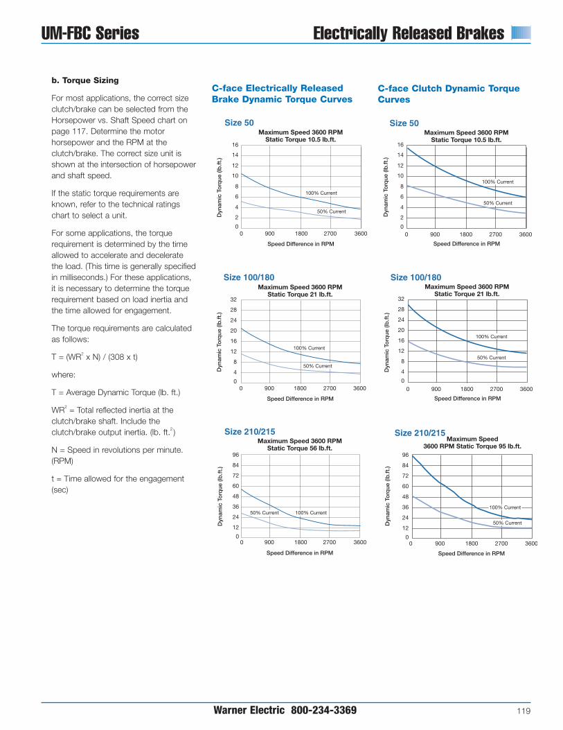
UM-FBC Series Electrically Released Brakes
Warner Electric 800-234-3369 119
b. Torque Sizing
For most applications, the correct sizeclutch/brake can be selected from theHorsepower vs. Shaft Speed chart onpage 117. Determine the motorhorsepower and the RPM at theclutch/brake. The correct size unit isshown at the intersection of horsepowerand shaft speed.
If the static torque requirements areknown, refer to the technical ratingschart to select a unit.
For some applications, the torquerequirement is determined by the timeallowed to accelerate and deceleratethe load. (This time is generally specifiedin milliseconds.) For these applications,it is necessary to determine the torquerequirement based on load inertia andthe time allowed for engagement.
The torque requirements are calculatedas follows:
T = (WR2 x N) / (308 x t)
where:
T = Average Dynamic Torque (lb. ft.)
WR2 = Total reflected inertia at theclutch/brake shaft. Include theclutch/brake output inertia. (lb. ft.2 )
N = Speed in revolutions per minute.(RPM)
t = Time allowed for the engagement(sec)
50% Current
16
32
Size 50
Size 100/180
96
Size 210/215
Maximum Speed 3600 RPM Static Torque 10.5 lb.ft.
Maximum Speed 3600 RPM Static Torque 21 lb.ft.
Maximum Speed 3600 RPM Static Torque 56 lb.ft.
0
12
8
4
0
28
24
20
16
12
8
4
0
84
72
60
48
36
24
12
0
14
10
6
2
0
0 900 1800 2700 3600
100% Current
50% Current
Dyn
amic
To
rque
(lb
.ft.
)D
ynam
ic T
orq
ue (l
b.f
t.)
Dyn
amic
To
rque
(lb
.ft.
)
Speed Difference in RPM
Speed Difference in RPM
Speed Difference in RPM
900 1800 2700 3600
900 1800 2700 3600
100% Current50% Current
100% Current
32
Size 100/180Maximum Speed 3600 RPM
Static Torque 21 lb.ft.
0
28
24
20
16
12
8
4
0
50% Current
Dyn
amic
To
rque
(lb
.ft.
)Speed Difference in RPM
900 1800 2700 3600
100% Current
50% Current
16
Size 50Maximum Speed 3600 RPM
Static Torque 10.5 lb.ft.
12
8
4
0
14
10
6
2
0 900 1800 2700 3600
100% Current
Dyn
amic
To
rque
(lb
.ft.
)
Speed Difference in RPM
96
Size 210/215 Maximum Speed
3600 RPM Static Torque 95 lb.ft.
84
72
60
48
36
24
12
00
Dyn
amic
To
rque
(lb
.ft.
)
Speed Difference in RPM
900 1800 2700 3600
100% Current
50% Current
C-face Electrically ReleasedBrake Dynamic Torque Curves
C-face Clutch Dynamic TorqueCurves
50% Current
16
32
Size 50
Size 100/180
96
Size 210/215
Maximum Speed 3600 RPM Static Torque 10.5 lb.ft.
Maximum Speed 3600 RPM Static Torque 21 lb.ft.
Maximum Speed 3600 RPM Static Torque 56 lb.ft.
0
12
8
4
0
28
24
20
16
12
8
4
0
84
72
60
48
36
24
12
0
14
10
6
2
0
0 900 1800 2700 3600
100% Current
50% Current
Dyn
amic
To
rque
(lb
.ft.
)D
ynam
ic T
orq
ue (l
b.f
t.)
Dyn
amic
To
rque
(lb
.ft.
)
Speed Difference in RPM
Speed Difference in RPM
Speed Difference in RPM
900 1800 2700 3600
900 1800 2700 3600
100% Current50% Current
100% Current
32
Size 100/180Maximum Speed 3600 RPM
Static Torque 21 lb.ft.
0
28
24
20
16
12
8
4
0
50% Current
Dyn
amic
To
rque
(lb
.ft.
)
Speed Difference in RPM
900 1800 2700 3600
100% Current
50% Current
16
Size 50Maximum Speed 3600 RPM
Static Torque 10.5 lb.ft.
12
8
4
0
14
10
6
2
0 900 1800 2700 3600
100% Current
Dyn
amic
To
rque
(lb
.ft.
)
Speed Difference in RPM
96
Size 210/215 Maximum Speed
3600 RPM Static Torque 95 lb.ft.
84
72
60
48
36
24
12
00
Dyn
amic
To
rque
(lb
.ft.
)
Speed Difference in RPM
900 1800 2700 3600
100% Current
50% Current
50% Current
16
32
Size 50
Size 100/180
96
Size 210/215
Maximum Speed 3600 RPM Static Torque 10.5 lb.ft.
Maximum Speed 3600 RPM Static Torque 21 lb.ft.
Maximum Speed 3600 RPM Static Torque 56 lb.ft.
0
12
8
4
0
28
24
20
16
12
8
4
0
84
72
60
48
36
24
12
0
14
10
6
2
0
0 900 1800 2700 3600
100% Current
50% Current
Dyn
amic
To
rque
(lb
.ft.
)D
ynam
ic T
orq
ue (l
b.f
t.)
Dyn
amic
To
rque
(lb
.ft.
)
Speed Difference in RPM
Speed Difference in RPM
Speed Difference in RPM
900 1800 2700 3600
900 1800 2700 3600
100% Current50% Current
100% Current
32
Size 100/180Maximum Speed 3600 RPM
Static Torque 21 lb.ft.
0
28
24
20
16
12
8
4
0
50% Current
Dyn
amic
To
rque
(lb
.ft.
)Speed Difference in RPM
900 1800 2700 3600
100% Current
50% Current
16
Size 50Maximum Speed 3600 RPM
Static Torque 10.5 lb.ft.
12
8
4
0
14
10
6
2
0 900 1800 2700 3600
100% Current
Dyn
amic
To
rque
(lb
.ft.
)
Speed Difference in RPM
96
Size 210/215 Maximum Speed
3600 RPM Static Torque 95 lb.ft.
84
72
60
48
36
24
12
00
Dyn
amic
To
rque
(lb
.ft.
)
Speed Difference in RPM
900 1800 2700 3600
100% Current
50% Current

Electrically Released Brakes UM-FBC Series
120 Warner Electric 800-234-3369
How to Order1. Specify model number and voltage
or the corresponding part number.
2. Specify conduit box, if desired. See the Controls Section.
3. Specify required control unit. See the Controls Section.
Ordering ExampleUM-50-1020FBC, 90V or 5370-273-036;5370-101-042 conduit box; CBC-300control.
UM Combination UM Model No. Voltage DC Part No.
UM-50-1020FBC 24 5370-273-037UM-50-1020FBC 90 5370-273-036UM-100-1020FBC 24 5370-273-153UM-100-1020FBC 90 5370-273-125
Motor Clutch/ UM-180-1020FBC 24 5370-273-047ER Brake UM-180-1020FBC 90 5370-273-046
UM-210-1020FBC 24 5371-273-013UM-210-1020FBC 90 5371-273-012UM-215-1020FBC 24 5371-273-099UM-215-1020FBC 90 5371-273-079
UM-50-2030FBC 24 5370-273-042UM-50-2030FBC 90 5370-273-041UM-100-2030FBC 24 5370-273-154
Input Clutch/ UM-100-2030FBC 90 5370-273-155ER Brake UM-180-2030FBC 24 5370-273-052
UM-180-2030FBC 90 5370-273-051UM-210-2030FBC 24 5371-273-018UM-210-2030FBC 90 5371-273-017UM-215-2030FBC 24 5371-273-100UM-215-2030FBC 90 5371-273-101
Accessories
Description UM Size Part No.
Conduit BoxUM series
5370-101-042All sizes
Base Mount Kit50/100 5370-101-036
for 2030 FBC180 5370-101-037
210/215 5371-101-039
Motor Mount Kit50/100 5370-101-010
for 1020 FBC180 5370-101-012
210/215 5371-101-012
Specifications (Max. Speed 3600 RPM)
Component Inertia–WR2 (lb. ft.2)1020 2030
Nominal Weight (lbs.) Armature Rotor w/Fan Output Input Rotor w/Fan NEMASize Voltage DC 1020 2030 (both) Hub Shaft and Hub Shaft Shaft and Hub Frame Size
5024
12 15 .018 .001 .001 .020 .001 .001 .020 56C/48Y90
10024
16 19 .046 .002 .002 .046 .002 .002 .046 56C/48Y90
18024
16 19 .046 .002 .002 .046 .002 .002 .046182C/143TC
90 184C/145TC
21024
36 47 .162 .016 .014 .190 .016 .015 .183213C/182TC
90 215C/184TC
21524
37 48 .162 .016 .016 .190 .017 .016 .183 213TC/215TC90
3. Select OptionsWarner Electric Enclosed UniModules canbe fitted with several accessories toextend their capacity and ease ofmounting.
4. Select ControlAll electrically released modules require acontrol with a potentiometer that will varybrake channel output. UM-FBC unitsrequire either a CBC-300 or a CBC500/550 control.

Warner Electric 800-234-3369 121
UM-FBC Series Electrically Released Brakes
All dimensions are nominal, unless otherwise noted.
Size A B C D E F G H J K L M N (Key)50 7.281 5.375 1.813 6.750 .625 .938 6.688 3.250 2.188 75° 5.531 4.438 3/16 x 3/16 x 1-1/4
100 7.281 5.375 1.813 6.750 .625 .938 6.688 3.250 2.188 75° 5.531 4.438 3/16 x 3/16 x 1-1/4
180 7.359 5.375 1.891 6.750 .875 .938 6.688 3.250 2.188 75° 5.531 4.438 3/16 x 3/16 x 1-1/4
210 9.688 7.031 2.500 9.250 1.125 .625 9.688 3.250 2.188 70° 6.869 5.766 1/4 x 1/4 x 2
215 10.568 7.44 3.125 9.25 1.375 1.2 9.688 3.250 2.188 70° 6.869 5.766 5/16 x 5/16 x 2
AV
C
L
J
G
N
M
HK
B
ED
F
OptionalConduit
Box
1/2" ConduitHole Both
Ends
1/2" Conduit HoleBoth Ends
20Brake
10MotorClutch
UM-1020 FBC Motor Clutch/Electrically Released Brake
Note: Conduit box is optional and is ordered separately.
For use with 1020, 1040, 20, 20 FBB and 1020 FBC Combinations.
Size A B C D E F Part No.50/100 9.25 8.25 11.00 8.000 3.50 .797 x .406 5370-101-010
180 9.25 8.25 11.00 8.000 4.50 .797 x .406 5370-101-012
210/215 11.50 10.50 12.00 9.000 5.25 .750 x .406 5371-101-012
Motor Mount (M)
A
E
DC
B
F (4) slots

Electrically Released Brakes UM-FBC Series
122 Warner Electric 800-234-3369
S
Q
I
O NN
M
TP
R
1/2" Conduit HoleBoth Ends
AB
U
EF
HG
D
CC
V
OptionalConduit
Box
1/2" ConduitHole Both
Ends
L
J
K
FH
20Brake
30Input Clutch
UM-2030 FBC Input Clutch/Electrically Released BrakeUM-2030 FBC-Input Clutch/Electrically Released Brake – Base Mounted
All dimensions are nominal, unless otherwise noted.
Size A B C Min. D E F G H I J K50 6.250 10.047 1.813 .625 6.219 1.109 4.000 .344 6.688 3.500 6.844
180 6.250 10.188 1.891 .875 6.219 1.109 4.000 .344 6.688 4.500 7.844
210 8.516 13.766 2.500 1.125 8.938 1.469 6.000 .438 9.688 5.250 9.906
Note: Mounting base and conduit box are optional and are orderedseparately.
Size L M N O P Q R S T U V50 2.000 6.000 .500 5.000 3.250 2.188 75° 5.531 4.438 1.125 2.203
180 3.000 6.625 .813 5.000 3.250 2.188 75° 5.531 4.438 1.125 2.203
210 3.375 9.000 .625 7.750 3.250 2.188 70° 6.859 5.766 1.625 2.203
For use with 2030 FBC units.
Size A B C D E F G Part No.50/100 6.000 5.000 6.219 4.000 .750 X .406 3.500 2.000 5370-101-036
180 6.625 5.000 6.219 4.000 .750 X .406 4.500 3.000 5370-101-037
210 9.000 7.750 8.938 6.000 .750 X .531 5.250 3.375 5371-101-019
Base (B)
B
D CA
G
E (4) Slots
F
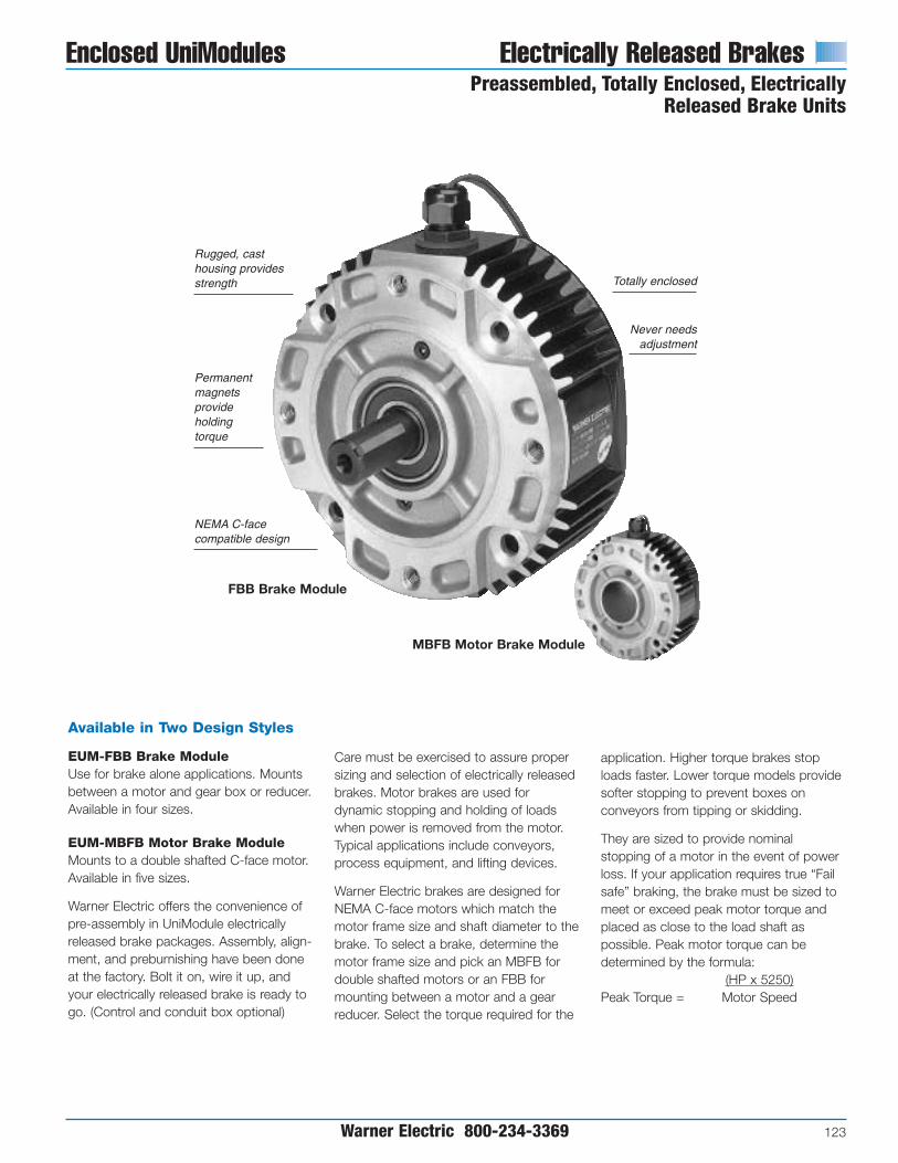
Warner Electric 800-234-3369 123
Enclosed UniModules Electrically Released BrakesPreassembled, Totally Enclosed, Electrically
Released Brake Units
Available in Two Design Styles
EUM-FBB Brake ModuleUse for brake alone applications. Mountsbetween a motor and gear box or reducer.Available in four sizes.
EUM-MBFB Motor Brake ModuleMounts to a double shafted C-face motor.Available in five sizes.
Warner Electric offers the convenience ofpre-assembly in UniModule electricallyreleased brake packages. Assembly, align-ment, and preburnishing have been doneat the factory. Bolt it on, wire it up, andyour electrically released brake is ready togo. (Control and conduit box optional)
MBFB Motor Brake Module
FBB Brake Module
Permanentmagnetsprovideholdingtorque
Rugged, casthousing providesstrength
NEMA C-facecompatible design
Totally enclosed
Never needsadjustment
Care must be exercised to assure propersizing and selection of electrically releasedbrakes. Motor brakes are used fordynamic stopping and holding of loadswhen power is removed from the motor.Typical applications include conveyors,process equipment, and lifting devices.
Warner Electric brakes are designed forNEMA C-face motors which match themotor frame size and shaft diameter to thebrake. To select a brake, determine themotor frame size and pick an MBFB fordouble shafted motors or an FBB formounting between a motor and a gearreducer. Select the torque required for the
application. Higher torque brakes stoploads faster. Lower torque models providesofter stopping to prevent boxes onconveyors from tipping or skidding.
They are sized to provide nominalstopping of a motor in the event of powerloss. If your application requires true “Failsafe” braking, the brake must be sized tomeet or exceed peak motor torque andplaced as close to the load shaft aspossible. Peak motor torque can bedetermined by the formula:
(HP x 5250)Peak Torque = Motor Speed

Electrically Released Brakes Enclosed UniModulesEUM-FBB, EUM-MBFB Selection
124 Warner Electric 800-234-3369
EUM-MBFB Frame Size Selection
NEMA EUM Bolt Hole Motor ShaftFrame Size Brake Size Mounting Circle Dia.
56C/48YEUM-50* 5.875 0.625
EUM-100**
182C/143TCEUM-180 5.875 0.875184C/145TC
213C/182TC EUM-210-7/8 7.25 0.875215C/184TC EUM-210 7.25 1.125
*For 56C/48Y C-frame motors 3/4 HP and smaller, the EUM-100 size may be used where extendedlife is desirable.
**The EUM-100 size is recommended for motors 1 HP and larger.
EUM-FBB Frame Size Selection
NEMA EUMFrame Size Size
56C/48YEUM-50*
EUM-100**
182C/143TCEUM-180184C/145TC
213C/182TCEUM-210215C/184TC
213TC/215TC EUM-215
*For 56C/48Y C-frame motors 3/4 HP andsmaller, the EUM-100 size may be usedwhere extended life is desirable.
**The EUM-100 size is recommended formotors 1 HP and larger.
Horsepower vs. Shaft Speed
Warner Electric Electrically ReleasedEnclosed UniModules are available in twostyles. The EUM-FBB Brake Module isused in brake only applications andmounts between a C-face motor and agear box or reducer. The EUM-MBFBMotor Brake Module mounts to the backof a double shafted motor.
Note: Care must be exercised whenselecting a brake to ensure it is sizedproperly for your application.
Verify that the brake will be cycledfrequently.
Determine the NEMA C-face frame sizeof your motor and/or reducer, andchoose the corresponding sizeEnclosed UniModule from the FrameSize Selection chart.
Size EUM-100 modules utilize a 5/8"diameter shaft to fit 56C/48Y motorframes with components of EUM-180units for higher torque and heatdissipation capacity than the EUM-50.
1. Select Configuration
a. FBB for NEMA C-face Mounting Between a Motor and Reducer
b. MBFB for NEMA C-face Mounting on the Back of a Double Shafted Motor
Verify that the brake will be cycledfrequently.
Determine the NEMA C-face frame sizeof your motor and/or reducer, andchoose the corresponding sizeEnclosed UniModule MBFB from theFrame Size Selection chart, and verifythat the motor shaft diameter andmounting bolt circle are the same for thebrake and the motor.
Size EUM-100 modules utilize a 5/8"diameter shaft to fit 56C/48Y motorframes with components of EUM-180units for higher torque and heatdissipation capacity than the EUM-50.
2. Determine Technical Requirements
Technical considerations for sizing andselection are torque and heat dissipation.Each merits careful consideration,especially heat dissipation as over time,use in excessive temperatureenvironments will have an adverse effecton bearing life and coil wire insulationintegrity.
Compare the calculated torquerequirement with the average dynamictorque ratings. Select a unit with adequatetorque. If the unit selected on torque isdifferent than the unit selected based onheat, select the larger size unit.
EUM HP/SS Chart
SHAFT SPEED AT CLUTCH (IN RPM)100 200 300 400 500 600 700 800 900 1000 1100 1200 1500 1800 2000 2400 3000 3600
1/4
1/2
3/4
1
1-1/2
2
3
5
7-1/2
10
HP
EUM-50
EUM-100/180
EUM-210/215

Warner Electric 800-234-3369 125
Enclosed UniModules Electrically Released Brakes
a. Heat Dissipation SizingFriction surfaces slip during the initialperiod of engagement and, as a result,heat is generated. The clutch/brakeselected must have a heat dissipationrating greater than the heat generatedby the application. Therefore, in highinertia or high cycle rate applications, itis necessary to check the heatdissipation carefully. Inertia, speed andcycle rate are the required parameters.
Heat dissipation requirement iscalculated as follows:
E = 1.7 x WR2 x (N/100)2 x F
where:
E = Heat (lb. ft./min.)
WR2 = Total reflected inertia at theclutch/brake shaft. Include theclutch/brake output inertia. (lb.ft.2 )
N = Speed in revolutions per minute.(RPM)
F = Cycle rate in cycles per minute(CPM)
Compare the calculated heat generatedin the application to the unit ratingsusing the heat dissipation curves. Selectthe appropriate unit that has adequateheat dissipation ability.
b. Torque Sizing
For most applications, the correct sizeclutch/brake can be selected from theHorsepower vs. Shaft Speed chart.Determine the motor horsepower andthe RPM at the clutch/brake. Thecorrect size unit is shown at theintersection of horsepower and shaftspeed.
If the static torque requirements areknown, refer to the technical ratingschart to select a unit.
For some applications, the torquerequirement is determined by the timeallowed to accelerate and deceleratethe load. (This time is generally specifiedin milliseconds.) For these applications,it is necessary to determine the torquerequirement based on load inertia andthe time allowed for engagement.
The torque requirements are calculatedas follows:
T = (WR2 x N) / (308 x t)
where:
T = Average Dynamic Torque (lb. ft.)
WR2 = Total reflected inertia at theclutch/brake shaft. Include theclutch/brake output inertia. (lb. ft.2 )
N = Speed in revolutions per minute.(RPM)
t = Time allowed for the engagement(sec)
10000
EUM 50
8000
4000
6000
2000
0900 1800 2700 3600
Fan Cooled
Standard
Hea
t D
issi
pat
ion
(lb.f
t./m
in.)
Speed (RPM)
10000
EUM 100/180
8000
4000
6000
2000
0900 1800 2700 3600
Fan Cooled
Standard
Hea
t D
issi
pat
ion
(lb.f
t./m
in.)
Speed (RPM)
20000
EUM 210/215 (fan not available for 215)
16000
8000
12000
4000
0900 1800 2700 3600
Fan Cooled
Standard
Hea
t D
issi
pat
ion
(lb.f
t./m
in.)
Speed (RPM)
10000
EUM 50
8000
4000
6000
2000
0900 1800 2700 3600
Fan Cooled
Standard
Hea
t D
issi
pat
ion
(lb.f
t./m
in.)
Speed (RPM)
10000
EUM 100/180
8000
4000
6000
2000
0900 1800 2700 3600
Fan Cooled
Standard
Hea
t D
issi
pat
ion
(lb.f
t./m
in.)
Speed (RPM)
20000
EUM 210/215 (fan not available for 215)
16000
8000
12000
4000
0900 1800 2700 3600
Fan Cooled
Standard
Hea
t D
issi
pat
ion
(lb.f
t./m
in.)
Speed (RPM)
Heat Dissipation Curves
50% Current
16 32
Size 50 Size 100/180
96
Size 210/215 Maximum Speed 3600 RPM
Static Torque 10.5 lb.ft.Maximum Speed 3600 RPM
Static Torque 21 lb.ft.Maximum Speed 3600 RPM
Static Torque 56 lb.ft.
0
12
8
4
0
28
24
20
16
12
8
4
0
84
72
60
48
36
24
12
0
14
10
6
2
00 900 1800 2700 3600
100% Current
50% Current
Dyn
amic
To
rque
(lb
.ft.
)
Dyn
amic
To
rque
(lb
.ft.
)
Dyn
amic
To
rque
(lb
.ft.
)
Speed Difference in RPM Speed Difference in RPM Speed Difference in RPM
900 1800 2700 3600 900 1800 2700 3600
100% Current50% Current
100% Current
C-face Electrically Released Brakes Dynamic Torque Curves
50% Current
16 32
Size 50 Size 100/180
96
Size 210/215 Maximum Speed 3600 RPM
Static Torque 10.5 lb.ft.Maximum Speed 3600 RPM
Static Torque 21 lb.ft.Maximum Speed 3600 RPM
Static Torque 56 lb.ft.
0
12
8
4
0
28
24
20
16
12
8
4
0
84
72
60
48
36
24
12
0
14
10
6
2
00 900 1800 2700 3600
100% Current
50% Current
Dyn
amic
To
rque
(lb
.ft.
)
Dyn
amic
To
rque
(lb
.ft.
)
Dyn
amic
To
rque
(lb
.ft.
)
Speed Difference in RPM Speed Difference in RPM Speed Difference in RPM
900 1800 2700 3600 900 1800 2700 3600
100% Current50% Current
100% Current
50% Current
16 32
Size 50 Size 100/180
96
Size 210/215 Maximum Speed 3600 RPM
Static Torque 10.5 lb.ft.Maximum Speed 3600 RPM
Static Torque 21 lb.ft.Maximum Speed 3600 RPM
Static Torque 56 lb.ft.
0
12
8
4
0
28
24
20
16
12
8
4
0
84
72
60
48
36
24
12
0
14
10
6
2
00 900 1800 2700 3600
100% Current
50% Current
Dyn
amic
To
rque
(lb
.ft.
)
Dyn
amic
To
rque
(lb
.ft.
)
Dyn
amic
To
rque
(lb
.ft.
)
Speed Difference in RPM Speed Difference in RPM Speed Difference in RPM
900 1800 2700 3600 900 1800 2700 3600
100% Current50% Current
100% Current

Electrically Released Brakes Enclosed UniModulesPreassembled, Totally Enclosed, ElectricallyReleased Brake Units
126 Warner Electric 800-234-3369
Specifications
Component Inertia –WR2 (lb.ft.2)FBB MBFB
Static Max. Total Armature Hub Shaft NEMASize Voltage DC Torque (lb.ft.) Speed (RPM) Weight (lbs.) (lb.ft.2) Hub Shaft Spliced Input Frame Size50 90 6 3600 8.6 .009 .001 .0005 .001 .0003 56C/48Y
100 90 12 3600 10.5 .023 .002 .002 .002 .002 56C/48Y
180 90 12 3600 10.5 .023 .002 .002 .002 .002182C/143TC184C/145TC
210 90 32 3600 27 .081 .016 .016 .016 .007213C/182TC215C/184TC
3. Select OptionsWarner Electric Enclosed UniModules canbe fitted with several accessories toextend their capacity and ease ofmounting.
4. Select ControlAll electrically released modules require acontrol with a potentiometer that will varybrake channel output. For FBB and MBFBbrake modules, the CBC-160, CBC-200,CBC-300, or CBC-500/550 isrecommended. The FBC units requireeither a CBC-300 or a CBC 500/550control.

Accessories
Description FBB Size Part No.
Conduit BoxFBB series
5370-101-042All sizes
Motor Mount Kit 50/100/180 5370-101-012for 20 FBB 210/215 5371-101-012
EUM Description EUM Model No. Static Torque (lb.ft.) Part No.
EUM-50-20FBB-6 6 5370-169-983
EUM-50-20FBB-10 10.5 5370-169-986
EUM-100-20FBB-12 12 5370-169-989
EUM-100-20FBB-21 21 5370-169-992FBB EUM-180-20FBB-12 12 5370-169-995Brake Module
EUM-180-20FBB-21 21 5370-169-998(90VDC)
EUM-210-20FBB-32 32 5371-169-078
EUM-210-20FBB-56 56 5371-169-082
EUM-215-20FBB-32 32 5371-169-086
EUM-215-20FBB-56 56 5371-169-090
EUM-50-20MBFB-6 6 5370-169-965EUM-50-20MBFB-10 10.5 5370-169-968
EUM-100-20MBFB-12 12 5370-169-971
MBFB EUM-100-20MBFB-21 21 5370-169-974
Motor Brake Module EUM-180-20MBFB-12 12 5370-169-977(90VDC) EUM-180-20MBFB-21 21 5370-169-980
EUM-210-7/8-20MBFB-32 32 5371-169-064EUM-210-7/8-20MBFB-56 56 5371-169-068EUM-210-20MBFB-32 32 5371-169-056EUM-210-20MBFB-56 56 5371-169-060
Warner Electric 800-234-3369 127
Enclosed UniModules Electrically Released BrakesSelection/Ordering Information
How to Order1. Specify model number and voltage
or the corresponding part number.
2. Specify conduit box, if desired. See the Controls Section.
3. Specify required control unit. See the Controls Section.
Selection Procedure
Note: Care must be exercised whenselecting the proper brake size for yourapplication.
The selection charts list NEMA motorframe sizes, motor shaft diameters, andthe matching FBB or MBFB brakes. To select a brake:
1. Determine the motor NEMA C-faceframe size.
2. Select brake configurationa. FBB to mount between a NEMA
C-face motor and a gear reducer.b. MBFB to mount on double
shafted NEMA C-face motors.
3. Select the brake model from thecharts by the torque required – highertorque for faster stopping, lowertorque for longer, “soft” stopping.
Note: Size 100 brakes are typically usedon motors with a rating of 1 HP or greater.
4. Important: Verify that the motor shaftdiameter and mounting bolt circledimensions are the same for the brakeselected and the motor.
Control SelectionAn optional conduit box enclosure isavailable. All electrically released unitsrequire a control with a potentiometer tovary brake channel output. For FBB andMBFB brake modules, control modelsCBC-160, CBC-200, CBC-300, or CBC-500/550 are recommended. (See ControlsSection.)
Frame Size
FBB MBFBNEMA Bolt Hole Motor to Motor Brake
EUM Size Frame Size Mounting Circle Reducer Shaft Dia. Shaft Dia.EUM-50 56C 5 7/8 5/8 5/8
EUM-100 56C 5 7/8 5/8 5/8
143TCEUM-180145TC
5 7/8 7/8 7/8
213TCEUM-210-7/8215TC
7 1/4 N/A 7/8
182TCEUM-210184TC
7 1/4 1 1/8 1 1/8
213TCEUM-215215TC
7 1/4 1 3/8 N/A
Ordering ExampleEUM-50-20FBB-6, 90V or 5370-169-983;5370-101-042 conduit box; CBC-160-2control.

Electrically Released Brakes
128 Warner Electric 800-234-3369
EUM-FBB Series
B
R
S
P
T
N
OptionalConduit Box
F
A
D
K
E
H M
J
G
L
C
1/2" conduit holeboth ends
EUM-FBB Brake Module
All dimensions are nominal, unless otherwise noted.
Size A Max. B C Max. D E Max. F G Dia. H Dia.3/8-16 UNC-2A
50 5.188 3.125 .500 1.000 .156 (4) Equally Spaced 6.688 .625on 5.875 Dia.
3/8-16 UNC-2A100 5.266 3.125 .500 1.000 .156 (4) Equally Spaced 6.688 .625
on 5.875 Dia.
3/8-16 UNC-2A180 5.266 3.125 .500 1.000 .156 (4) Equally Spaced 6.688 .875
on 5.875 Dia.
1/2-13 UNC-2A210 7.578 4.609 .594 1.500 .313 (4) Equally Spaced 9.344 1.125
on 7.250 Dia.
1/2-13 UNC-2A215 7.578 4.609 .594 1.500 .313 (4) Equally Spaced 9.344 1.375
on 7.250 Dia.
Size J Key K Min. L Pilot Dia. M Dia. N P R S Integral Key T
50 3/16 x 3/16 x 1-1/4 1.813 4.500 .625 30° 2.188 45° 3/16 x 3/16 3.125
100 .3/16 x 3/16 x 1-1/4 1.891 4.500 .625 30° 2.188 45° 3/16 x 3/16 3.125
180 3/16 x 3/16 x 1-1/4 1.891 4.500 .875 30° 2.188 45° 3/16 x 3/16 3.125
210 1/4 x 1/4 x 2 2.500 8.500 1.125 25° 2.188 45° 1/4 x 1/4 3.125
215 5/16 x 5/16 x 2 2.500 8.500 1.375 25° 2.188 45° 5/16 x 5/16 3.125

Warner Electric 800-234-3369 129
EUM-MBFB Series Electrically Released Brakes
AE B C
D
J
I
K
OptionalConduit Box
H
F
G
1/2" conduit holeboth ends
EUM-MBFB Motor Brake Module
All dimensions are nominal, unless otherwise noted.
HMax.
Size A B C Max. D E Max. F G Dia. Dia. Length Integral Key I J K50 3.125 1.000 .156 .219 .300 3/8-16 UNC-2A 6.688 .625 2.094 3/16 x 3/16 30° 2.188 3.125
100 3.125 1.000 .156 .219 .300 3/8-16 UNC-2A 6.688 .625 2.094 3/16 x 3/16 30° 2.188 3.125
180 3.125 1.000 .156 .219 .500 3/8-16 UNC-2A 6.688 .875 2.063 3/16 x 3/16 30° 2.188 3.125
210-7/8" 4.609 1.500 .313 .250 .594 1/2-13 UNC-2A 9.344 .875 2.766 3/16 x 3/16 30° 2.188 3.125
210 4.609 1.500 .313 .250 .594 1/2-13 UNC-2A 9.344 1.125 2.766 1/4 x 1/4 30° 2.188 3.125

Electrically Released Brakes Electro Modules
130 Warner Electric 800-234-3369
Electro Module, Electrically Released Brakesand Clutch/Brake Units for DynamicStopping and Cycling Applications
NEMA C-facecompatible design
UL Listed and CSA Certified
Brake automaticallyengages when power fails.
Never needsadjustment; automaticallycompensates for wear.
Holding torque provided bypowerful ceramic type
permanent magnets.
Complete torque control for soft starts and stops or
instantaneous engagement.
Rugged precision cast housing
MBFB Motor Brake Module
Shaft Mounted UnitsFBB Brake ModuleFBC Brake Module for use with a clutch
Warner Electric’s unique design employspowerful permanent magnets for maximumtorque when power is removed from thebrake coil. A small amount of electricalpower applied to the brake coil nullifies thepermanent magnets’ force and the brakereleases. No springs to limit cycle rates.Never nay adjustment. No lubrication.These brakes are recommended fordynamic cycling operations only.
Available in Three Design Styles
EM-FBB Brake ModuleUse for brake alone applications. Mountsbetween a C-face motor and a gear box or reducer. Available in five sizes.
EM-MBFB Motor Brake ModuleMounts to the back of a double shaftedmotor. Available in four sizes.
EM-FBC Brake Module for use witha ClutchCombine with a motor or input clutch forclutch/brake applications. Three sizes areavailable.
Specifications
Component Inertia –WR2 (lb.ft.2)
Static Torque (lb.ft.) Max. Total Armature NEMASize Voltage DC Brake Clutch Speed (RPM) Weight (lbs.) FBB/MBFB FBC Hub Shaft Frame Size
EM-5024
10.5 16 3600 8.6 .0071 .014 .003 .001 56C/48Y90
EM-100 90 21 — 3600 10.5 .018 — .004 .002 56C/48Y
EM-18024
21 30 3600 10.5 .018 .036 .004 .002182C/143TC
90 184C/145TC
EM-21024
56 95 3600 27 .081 .162 .027 .017213C/182TC
90 215C/184TC

c. For FBC Modular Units, BaseMounting
Verify that brake will be cycledfrequently, and will be used with aninput clutch (EM-30) for base mounting.
Select the correct size module from theHorsepower vs. Shaft Speed chart (atthe bottom of this page) by determiningthe motor horsepower and RPM at themodule location. The correct size EM isshown at the intersection of the HP andoperating speed. For additional sizinginformation, refer to the technical sizingprocedure (step 2).
Warner Electric 800-234-3369 131
Electro Modules Electrically Released Brakes
Horsepower vs. Shaft Speed
EM HP/Shaft Speed Chart11/15/99page 183
1/4
1/2
3/4
1
HP SHAFT SPEED AT CLUTCH (IN RPM)
Horsepower vs. Shaft Speed
100 200 300 400 500 600 700 800 900 1000 1100 1200 1500 1800 2000 2400 3000 3600
1-1/2
2
3
5
7-1/2
EM-50
EM-100 or EM-180
EM-210 or EM-215
FBB AND MBFB Frame SizeSelection
NEMA EMFrame Size Size
56C/48YEM-50*
EM-100**
182C/143TCEM-180184C/145TC
213C/182TCEM-210215C/184TC
213TC/215TC EM-215
*For 56C/48Y C-frame motors 3/4 HP andsmaller, the EM-100 size may be used whereextended life is desirable.
**The EM-100 size is recommended for motors1 HP and larger.
FBC Frame Size Selection
NEMA EMFrame Size Size
56C/48YEM-50*
EM-100**
182C/143TCEM-180184C/145TC
213C/182TCEM-210215C/184TC
For torque ratings, refer to the “Specifications”chart. Note that separate torque ratings arelisted for the clutch and brake segments of themodule.
* For 56C/48Y C-frame motors 3/4 HP andsmaller, the EM-100 size may be used whereextended life is desirable.
** The EM-100 size is recommended for motors1 HP and larger.
EM-FBB, EM-FBC, EM-MBFB Selection
Warner Electric Electrically ReleasedElectro Modules are available in threestyles. The EM-FBB Brake Module is usedin brake only applications and mountsbetween a C-face motor and a gear boxor reducer. The EM-MBFB Motor BrakeModule mounts to the back of a doubleshafted motor. The EM-FBC Brake Moduleis combined with a motor clutch (EM-10)or an input clutch (EM-30) forclutch/electrically released brakeapplications.
Note: Care must be exercised whenselecting a brake to ensure it is sizedproperly for your application.
Verify that the brake will be cycledfrequently.
Determine the NEMA C-face frame sizeof your motor and/or reducer, andchoose the corresponding size ElectroModule from the Frame Size Selectionchart.
1. Select Configuration
a. For FBB and MBFB ModulesNEMA C-face Mounting
Size EM-100 modules utilize a 5/8"diameter shaft to fit 56C/48Y motorframes with components of EM-180units for higher torque and heatdissipation capacity than the EM-50
Select Brake Configuration: use an EM-FBB for mounting between a motor anda reducer; or an EM-MBFB for mountingon the rear of a double shafted motor.NOTE: When selecting an MBFB,ensure the shaft dimensions on the rearof the motor are compatible with theEM-MBFB unit selected.
b. For FBC Modular Units, NEMAC-face Mounting
Verify that brake will be cycledfrequently, and will be used with a motormounted clutch (EM-10) for C-facemounting.
Determine the NEMA C-face frame sizeof your motor and/or reducer, andchoose the corresponding size ElectroModule from the Frame Size Selectionchart.

Electrically Released Brakes Electro Modules
132 Warner Electric 800-234-3369
2. Determine TechnicalRequirementsTechnical considerations for sizing andselection are torque and heat dissipation.Each merits careful consideration,especially heat dissipation as over time,use in excessive temperatureenvironments will have an adverse effecton bearing life and coil wire insulationintegrity.
Compare the calculated torquerequirement with the average dynamictorque ratings. Select a unit with adequatetorque. If the unit selected on torque isdifferent than the unit selected based onheat, select the larger size unit.
a. Heat Dissipation SizingFriction surfaces slip during the initialperiod of engagement and, as a result,heat is generated. The clutch/brakeselected must have a heat dissipationrating greater than the heat generatedby the application. Therefore, in highinertia or high cycle rate applications, itis necessary to check the heatdissipation carefully. Inertia, speed andcycle rate are the required parameters.
Heat dissipation requirement iscalculated as follows:
E = 1.7 x WR2 x (N/100)2 x F
where:
E = Heat (lb. ft./min.)
WR2 = Total reflected inertia at theclutch/brake shaft. Include theclutch/brake output inertia. (lb.ft.2 )
N = Speed in revolutions per minute.(RPM)
F = Cycle rate in cycles per minute(CPM)
Compare the calculated heat generatedin the application to the unit ratingsusing the heat dissipation curves. Selectthe appropriate unit that has adequateheat dissipation ability.
b. Torque Sizing
For most applications, the correct sizeclutch/brake can be selected from theHorsepower vs. Shaft Speed chart onpage 131. Determine the motorhorsepower and the RPM at theclutch/brake. The correct size unit isshown at the intersection of horsepowerand shaft speed.
If the static torque requirements areknown, refer to the technical ratingschart to select a unit.
For some applications, the torquerequirement is determined by the timeallowed to accelerate and decelerate theload. (This time is generally specified inmilliseconds.) For these applications, it isnecessary to determine the torquerequirement based on load inertia andthe time allowed for engagement.
The torque requirements are calculatedas follows:
T = (WR2 x N) / (308 x t)
where:
T = Average Dynamic Torque (lb. ft.)
WR2 = Total reflected inertia at theclutch/brake shaft. Include theclutch/brake output inertia. (lb. ft.2 )
N = Speed in revolutions per minute.(RPM)
t = Time allowed for the engagement(sec)
0
6000
12000
18000
24000
30000
36000
0 3600900 1800 2700
Speed (RPM)
Hea
t D
issi
pat
ion
(ft.
lbs.
/min
.)
Size 210/215Maximum Speed 3600 RPM
250° F
200° F
0
3000
6000
9000
12000
15000
18000
0 3600900 1800 2700
Speed (RPM)
Hea
t D
issi
pat
ion
(ft.
lbs.
/min
.)
Size 100/180Maximum Speed 3600 RPM
250° F
200° F
0 36000
4000
8000
12000
2000
6000
10000
900 1800 2700
Speed (RPM)
Hea
t D
issi
pat
ion
(ft.
lbs.
/min
.)
Size 50Maximum Speed 3600 RPM
200° F
250° F
Heat Dissipation Curves
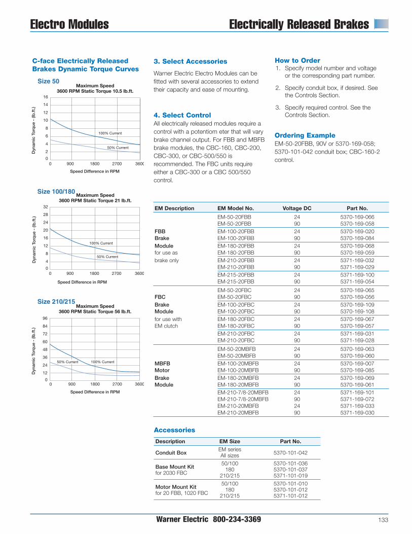
Warner Electric 800-234-3369 133
Electro Modules Electrically Released Brakes
50% Current
16
32
Size 50
Size 100/180
96
Size 210/215
Maximum Speed3600 RPM Static Torque 10.5 lb.ft.
Maximum Speed3600 RPM Static Torque 21 lb.ft.
Maximum Speed3600 RPM Static Torque 56 lb.ft.
0
12
8
4
0
28
24
20
16
12
8
4
0
84
72
60
48
36
24
12
0
14
10
6
2
0
0 900 1800 2700 3600
100% Current
50% Current
Dyn
amic
To
rque
- (l
b.f
t.)
Dyn
amic
To
rque
- (l
b.f
t.)
Dyn
amic
To
rque
- (l
b.f
t.)
Speed Difference in RPM
Speed Difference in RPM
Speed Difference in RPM
900 1800 2700 3600
900 1800 2700 3600
100% Current50% Current
100% Current
3. Select Accessories
Warner Electric Electro Modules can befitted with several accessories to extendtheir capacity and ease of mounting.
4. Select ControlAll electrically released modules require acontrol with a potentiom eter that will varybrake channel output. For FBB and MBFBbrake modules, the CBC-160, CBC-200,CBC-300, or CBC-500/550 isrecommended. The FBC units requireeither a CBC-300 or a CBC 500/550control.
EM Description EM Model No. Voltage DC Part No.
EM-50-20FBB 24 5370-169-066EM-50-20FBB 90 5370-169-058
FBB EM-100-20FBB 24 5370-169-020Brake EM-100-20FBB 90 5370-169-084Module EM-180-20FBB 24 5370-169-068for use as EM-180-20FBB 90 5370-169-059brake only EM-210-20FBB 24 5371-169-032
EM-210-20FBB 90 5371-169-029EM-215-20FBB 24 5371-169-100EM-215-20FBB 90 5371-169-054
EM-50-20FBC 24 5370-169-065FBC EM-50-20FBC 90 5370-169-056Brake EM-100-20FBC 24 5370-169-109Module EM-100-20FBC 90 5370-169-108for use with EM-180-20FBC 24 5370-169-067EM clutch EM-180-20FBC 90 5370-169-057
EM-210-20FBC 24 5371-169-031EM-210-20FBC 90 5371-169-028
EM-50-20MBFB 24 5370-169-063EM-50-20MBFB 90 5370-169-060
MBFB EM-100-20MBFB 24 5370-169-007Motor EM-100-20MBFB 90 5370-169-085Brake EM-180-20MBFB 24 5370-169-069Module EM-180-20MBFB 90 5370-169-061
EM-210-7/8-20MBFB 24 5371-169-101EM-210-7/8-20MBFB 90 5371-169-072EM-210-20MBFB 24 5371-169-033EM-210-20MBFB 90 5371-169-030
How to Order1. Specify model number and voltage
or the corresponding part number.
2. Specify conduit box, if desired. Seethe Controls Section.
3. Specify required control. See theControls Section.
Ordering ExampleEM-50-20FBB, 90V or 5370-169-058;5370-101-042 conduit box; CBC-160-2control.
Accessories
Description EM Size Part No.
Conduit BoxEM series
5370-101-042All sizes
Base Mount Kit50/100 5370-101-036
for 2030 FBC180 5370-101-037
210/215 5371-101-019
Motor Mount Kit50/100 5370-101-010
for 20 FBB, 1020 FBC180 5370-101-012
210/215 5371-101-012
C-face Electrically ReleasedBrakes Dynamic Torque Curves

Electrically Released Brakes EM-FBB Series
134 Warner Electric 800-234-3369
EM-FBB Brake Module Dim11/15/99page 184
B
A
C D
K
J
F
E
H M
LG
R
S
P
N 1/2" NPT
EM-20 FBB Brake Module
All dimensions are nominal, unless otherwise noted.
Size A Max. B C Max. D E Max. F G Dia. H Dia. J K Min. L Pilot Dia. M Dia. N P Min. R S Key
3/8-16 UNC-2A 3/16 x50/100 5.188 3.125 .500 1.000 .156 (4) Equally Spaced 6.688 .625 3/16 x 1.813 4.500 .625 30° 36 45° 3/16 x 3/16
on 5.875 Dia. 1-3/8
3/8-16 UNC-2A 3/16 x180 5.266 3.125 .500 1.000 .156 (4) Equally Spaced 6.688 .875 3/16 x 1.891 4.500 .875 30° 36 45° 3/16 x 3/16
on 5.875 Dia. 1-3/8
1/2-13 UNC-2A 1/4 x210 7.578 4.609 .594 1.500 .313 (4) Equally Spaced 9.344 1.125 1/4 x 2.500 8.500 1.125 25° 36 45° 1/4 x 1/4
on 7.250 Dia. 2
1/2-13 UNC-2A 5/16 x215 7.578 4.609 .594 1.500 .313 (4) Equally Spaced 9.344 1.375 5/16 x 2.500 8.500 1.375 25° 36 45° 5/16 x 5/16
on 7.250 Dia. 2

Warner Electric 800-234-3369 135
EM-FBC Series Electrically Released Brakes
B
ElectricalConnection
A
C D
K
J
F
E
N Mountingaccessoryplate
H M
LG
R
S
Q
P 1/2" NPT
EM-20FBC Brake Module foruse with a Clutch
All dimensions are nominal, unless otherwise noted.
Size A Max. B C Max. D E Max. F G Dia. H Dia. J K Min. L Pilot Dia. M Dia. N Max. P Q Min. R S Key
3/8-16 UNC-2A 3/16 x 3/16 x 50/100 5.188 3.125 .500 1.000 .156 (4) Equally Spaced 6.688 .625 3/16 x 1.813 4.500 .625 .531 30° 36 45° 3/16
on 5.875 Dia. 1-3/8
3/8-16 UNC-2A 3/16 x 3/16 x 180 5.266 3.125 .500 1.000 .156 (4) Equally Spaced 6.688 .875 3/16 x 1.891 4.500 .875 .531 30° 36 45° 3/16
on 5.875 Dia. 1-3/8
1/2-13 UNC-2A 1/4 x 1/4 x 210 7.578 4.609 .594 1.500 .313 (4) Equally Spaced 9.344 1.125 1/4 x 2.500 8.500 1.125 .797 25° 36 45° 1/4
on 7.250 Dia. 2

Electrically Released Brakes EM-MBFB Series
136 Warner Electric 800-234-3369
A
B C
D
E
F
H
G
J I
1/2" NPT
EM-20 MBFB Motor Brake Module
All dimensions are nominal, unless otherwise noted.
H
Size A B C Max. D E Max. F G Dia. Diameter Max. Length Required Key Size I J Min.
50/100 3.125 1.000 .156 .219 .300 3/8-16 UNC-2A 6.688 .625 2.094 3/16 x 3/16 30° 36
180 3.125 1.000 .156 .219 .500 3/8-16 UNC-2A 6.688 .875 2.063 3/16 x 3/16 30° 36
210-7/8" 4.609 1.500 .313 .250 .594 1/2-13 UNC-2A 9.344 .875 2.766 3/16 x 3/16 30° 36
210 4.609 1.500 .313 .250 .594 1/2-13 UNC-2A 9.344 1.125 2.766 1/4 x 1/4 30° 36

Specifications
AH AJ AK BB BF ES R S T UShaft Mtg. Bolt Mtg. Flange Pilot Mtg. Bolt Keyway Depth Over Keyway Mtg. Bolt Shaft
Module Size Length Center Dia. Pilot Dia. Depth Size, Qty. Length Keyway Width Ref. Dia.
50 2.06 5.875 4.500 5/323/8-16 UNC
1-1/4 .517 3/16 45° .6254 @ 90°
100 2.06 5.875 4.500 5/323/8-16 UNC
1-1/4 .517 3/16 45° .6254 @ 90°
180 2.04 5.875 4.500 5/323/8-16 UNC
1-1/4 .771 3/16 45° .875
4 @ 90°
210 2.56 7.250 8.500 5/161/2-13 UNC
2 .986 1/4 45° 1.1254 @ 90°
215 3.12 7.250 8.500 5/161/2-13 UNC
2 1.201 5/16 45° 1.3754 @ 90°
Note: Warner Electric Modules are designed to comply with the NEMA framestandards for mounting. Reference to each particular frame size is given in theindividual selection tables for each type of Warner Electric module.
NEMA Frame Standards Ordering Information
Warner Electric 800-234-3369 137
S
RAH
ESAJ
AK
BFBB
U
T
BF

Electrical Data/Coil Ratings
138 Warner Electric 800-234-3369
EC/EB-375 EC EBVoltage – DC 90 24 6 90 24 6
Resistance @ 20° C – Ohms 453.5 29.3 2.10 446.8 29.3 1.96
Current – Amperes .198 .82 2.85 .201 .82 3.07
Watts 17 20 17 18 20 18
Coil Build-up – milliseconds 62 60 59 50 60 52
Coil Decay – milliseconds 13 14 15 8 14 10
EC/EB-475 EC EBVoltage – DC 90 24 6 90 24 6
Resistance @ 20° C – Ohms 368.9 37.8 2.32 443.1 28.8 2.05
Current – Amperes .244 .64 2.58 .203 .88 2.93
Watts 22 15 16 18 21 18
Coil Build-up – milliseconds 92 91 90 80 75 70
Coil Decay – milliseconds 18 17 16 8 9 9
EC/EB-650 EC EBVoltage – DC 90 24 6 90 24 6
Resistance @ 20° C – Ohms 225 17.7 1.16 257.2 18.3 1.24
Current – Amperes .4 1.36 5.19 .35 1.3 4.84
Watts 36 33 31 32 31 29
Coil Build-up – milliseconds 120 115 110 112 108 105
Coil Decay – milliseconds 20 20 20 12 13 14
FB/ER-375, 475, 650 FB-375 FB-475 FB-650Voltage – DC 90 24 90 24 90 24
Resistance @ 20° C – Ohms 446 29 310 22 235 16
Current – Amperes .201 .822 .300 1.09 .380 1.426
Watts 18 19 27 26 34 34
Coil Build-up – milliseconds 40 40 80 80 90 90
Coil Decay – milliseconds 5 10 8 10 10 10
ER-825, 1225 ER-825 ER-1225Voltage – DC 90 35-75
Resistance @ 20° C – Ohms 304 235
Current – Amperes .29 .383
Watts 26 35
Coil Build-up – milliseconds 400 700
Coil Decay – milliseconds 20 20
EC/EB-825 EC EBVoltage – DC 90 24 6 90 24 6
Resistance @ 20° C – Ohms 221 20.9 1.098 223.3 20.4 1.27
Current – Amperes .407 1.15 5.464 .4 1.18 4.74
Watts 37 28 33 36 28 28
Coil Build-up – milliseconds 225 200 180 170 170 170
Coil Decay – milliseconds 130 122 115 80 75 70
EC/EB-1000 EC EBVoltage – DC 90 24 6 90 24 6
Resistance @ 20° C – Ohms 248.7 19.7 1.23 248.7 19.7 1.23
Current – Amperes .36 1.22 4.87 .36 1.22 4.87
Watts 33 29 29 33 29 29
Coil Build-up – milliseconds 250 235 220 235 220 205
Coil Decay – milliseconds 70 75 80 70 75 80
EC/EB-1225 EC EBVoltage – DC 90 24 6 90 24 6
Resistance @ 20° C – Ohms 207.3 15.1 1.04 261.7 22.3 1.33
Current – Amperes .43 1.59 5.79 .34 1.08 4.5
Watts 39 38 35 31 26 27
Coil Build-up – milliseconds 500 490 480 460 445 435
Coil Decay – milliseconds 220 230 240 190 160 140
ATC, ATTC, ATB, ATTB-25 ATC ATBVoltage – DC 6 24 90 6 24 90
Resistance @ 20° C – Ohms 1.37 20.2 290 1.37 20.2 290
Current – Amperes 4.38 1.19 .31 4.38 1.19 .31
Watts 26.3 28.6 27.9 26.3 28.6 27.9
Coil Build-up – milliseconds 145 145 145 145 145 145
Coil Decay – milliseconds 8 8 8 9 9 9
ATC, ATTC, ATB, ATTB-55 ATC ATBVoltage – DC 6 24 90 6 24 90
Resistance @ 20° C – Ohms 1.21 19.6 230 1.21 19.6 230
Current – Amperes 4.96 1.22 .39 4.96 1.22 .39
Watts 29.8 29.3 35.2 29.8 29.3 35.2
Coil Build-up – milliseconds 200 200 200 210 210 210
Coil Decay – milliseconds 20 20 20 35 35 35
ATC, ATTC, ATB, ATTB-115 ATC ATBVoltage – DC 6 24 90 6 24 90
Resistance @ 20° C – Ohms 1.02 16.5 182 1.02 16.5 182
Current – Amperes 5.91 1.46 .50 5.91 1.46 .50
Watts 35.4 35 44.6 35.4 35 44.6
Coil Build-up – milliseconds 145 145 145 150 150 150
Coil Decay – milliseconds 40 40 40 45 45 45

Electrical Data Coil Ratings
Warner Electric 800-234-3369 139
UM/EM/UMFB/EMFBUM/EM UMFB/EMFB
Clutch Brake Clutch Brake Clutch Brake Brake
90 90 24 24 6 6 90
Voltage – DC EM-50 452 452 31.8 31.8 1.86 1.86 446
Resistance EM-100 392 392 26.7 26.7 1.80 1.80 310
(ohms) EM-180 392 392 26.7 26.7 1.80 1.80 310
EM-210/215 248 248 17.9 17.9 1.22 1.22 205
EM-50 .199 .199 .755 .755 3.23 3.23 .210
AmperesEM-100 .230 .230 .896 .896 3.30 3.30 .300
EM-180 .230 .230 .896 .896 3.30 3.30 .300
EM-210/215 .363 .363 1.34 1.34 4.90 4.90 .380
EM-50 18 18 18 18 19 19 18
WattsEM-100 21 21 21.5 21.5 20 20 27
EM-180 21 21 21.5 21.5 20 20 27
EM-210/215 33 33 32 32 30 30 34
EM-50 52 53 52 53 52 53 40
Build-up EM-100 72 75 72 75 72 70 80
(millisecond) EM-180 72 75 72 75 72 70 80
EM-210/215 120 100 120 100 110 100 90
EM-50 6.2 5.0 6.2 5.0 6.5 5.0 5
Decay EM-100 12 10 12 10 12 10 8
(millisecond) EM-180 12 10 12 10 12 10 8
EM-210/215 20 10 20 10 20 10 10
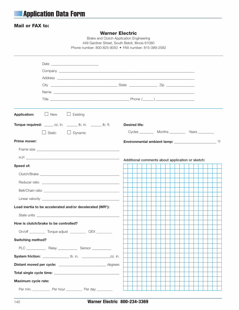
Application Data Form
140 Warner Electric 800-234-3369
Mail or FAX to:
Warner ElectricBrake and Clutch Application Engineering
449 Gardner Street, South Beloit, Illinois 61080Phone number: 800-825-9050 • FAX number: 815-389-2582
Date ___________________________
Company _____________________________________________________________________________
Address ______________________________________________________________________________
City ______________________________________ State ________________ Zip ________________
Name ________________________________________________________________________________
Title _____________________________________________ Phone ( ______ ) ______________________
Desired life:
Cycles ________ Months _________ Years _________
Environmental ambient temp: ________________________ °F
Additional comments about application or sketch:
Application: New Existing
Torque required: _____ oz. in. ______ lb. in. ______ lb. ft.
Static Dynamic
Prime mover:
Frame size _______________________________________________
H.P. _____________________________________________________
Speed of:
Clutch/Brake _____________________________________________
Reducer ratio ____________________________________________
Belt/Chain ratio ___________________________________________
Linear velocity ____________________________________________
Load inertia to be accelerated and/or decelerated (WR2 ):
State units _______________________________________________
How is clutch/brake to be controlled?
On/off _________ Torque adjust _________ OEX _________
Switching method?
PLC ___________ Relay ___________ Sensor ___________
System friction: _______________ lb. in. ________________oz. in.
Distant moved per cycle: ___________________________ degrees
Total single cycle time: _____________________________________
Maximum cycle rate:
Per min. __________ Per hour _________ Per day _________

Clutch and Brake Controls
Warner Electric 800-234-3369 141
Clutch and Brake Controls . . . . . . . . . . . . . . . . . . . . . . . . . 142
On-Off Controls
CBC-100 . . . . . . . . . . . . . . . . . . . . . . . . . . . . . . . . . . . . . . . . . . 144
CBC-150 . . . . . . . . . . . . . . . . . . . . . . . . . . . . . . . . . . . . . . . . . . 144
CBC-160 . . . . . . . . . . . . . . . . . . . . . . . . . . . . . . . . . . . . . . . . . . 145
CBC-801 . . . . . . . . . . . . . . . . . . . . . . . . . . . . . . . . . . . . . . . . . . 146
CBC-802 . . . . . . . . . . . . . . . . . . . . . . . . . . . . . . . . . . . . . . . . . . 147
CBC-400 . . . . . . . . . . . . . . . . . . . . . . . . . . . . . . . . . . . . . . . . . . 148
CBC-450 . . . . . . . . . . . . . . . . . . . . . . . . . . . . . . . . . . . . . . . . . . 149
Adjustable Torque Controls
MCS-103-1 . . . . . . . . . . . . . . . . . . . . . . . . . . . . . . . . . . . . . . . . 150
MCS-805-1 . . . . . . . . . . . . . . . . . . . . . . . . . . . . . . . . . . . . . . . . 151
MCS-805-2 . . . . . . . . . . . . . . . . . . . . . . . . . . . . . . . . . . . . . . . . 151
CBC-200 . . . . . . . . . . . . . . . . . . . . . . . . . . . . . . . . . . . . . . . . . . 152
CBC-300 . . . . . . . . . . . . . . . . . . . . . . . . . . . . . . . . . . . . . . . . . . 152
CBC-500 . . . . . . . . . . . . . . . . . . . . . . . . . . . . . . . . . . . . . . . . . . 153
CBC-550 . . . . . . . . . . . . . . . . . . . . . . . . . . . . . . . . . . . . . . . . . . 154
CBC-1825R. . . . . . . . . . . . . . . . . . . . . . . . . . . . . . . . . . . . . . . . 156
Overexcitation Controls
CBC-700 . . . . . . . . . . . . . . . . . . . . . . . . . . . . . . . . . . . . . . . . . . 158
CBC-750 . . . . . . . . . . . . . . . . . . . . . . . . . . . . . . . . . . . . . . . . . . 160
Closed Loop Position Control
CBC-1000 . . . . . . . . . . . . . . . . . . . . . . . . . . . . . . . . . . . . . . . . . 162
Appendix . . . . . . . . . . . . . . . . . . . . . . . . . . . . . . . . . . . . . . . . . 164
Questions & Answers . . . . . . . . . . . . . . . . . . . . . . . . . . . . . 165
Warner Electric’s electronic controls aredesigned to provide simple setup andmaximum performance when used withelectric clutches and brakes. Our controlsoffer a range of functions from on-off totorque control to over-excitation.
SelectionMany parameters beyond function canimpact control selection. Warner Electricproduces a variety of control options tosuit numerous application requirements.Control selection parameters include:
• Mounting Location – Panel or conduitbox mounting
• Switching – Relay switching of A.C. orD.C. lines or solid state switching
• Output Voltage – Controls are availablefor 6, 24 and 90 VDC clutch/brake coils
• Input Voltage – Controls with inputpower transformers are available forconnection to high voltage mains.
If your application requires somethingspecial, please call us. We will be happyto provide solutions.
Contents

ControlType
On-OffConduit BoxMount
On-Off Octal Socket Mount
On-OffPanel Mount
AdjustableTorque
Adjustable Accel-Decel
Overexcitation
Position Loop
Clutch and Brake Controls
142 Warner Electric 800-234-3369
Functions
On-Off (Basic start-stop)Many applications are controlled by energizingthe clutches and brakes with their rated D.C.voltages. Warner Electric controls are availablewith various mounting, input voltage andswitching options.
Adjustable Torque
(Soft start-stop)The torque transmitted by a clutch or brake isproportional to the coil current. Warner Electricoffers several products that provide torquecontrol for smooth and repeatable starts andstops.
Adjustable Accel-Decel
(Soft start-stop with full torque)Warner Electric offers a control that allows foradjustment of the acceleration and decelerationtime ramps to achieve a repeatable soft start orstop while still allowing for full torque.
Overexcitation
(Rapid cycling)The clutch/brake speed of response can beincreased for improved accuracy and perfor-mance through overexcitation, which is theapplication of a short high voltage pulse toprovide nearly instantaneous torque.
Position Loop
(Programmable cycling)Warner Electric’s CBC-1000 position loop controlsystem offers servo system performance withelectric clutch/brake economy in high accuracyindexing applications. The unique error correctioncapability of the CBC-1000 to achieve repeat-ability and accuracy makes this an ideal controlfor many applications.

Clutch and Brake Controls
Warner Electric 800-234-3369 143
Torque A.C. D.C. Customer Supplied Model No. of Control Input Output Over- Switching Page
Number Channels Channels Voltages Voltages Excitation Options Description Number
CBC-100-1 1 No 120 90 No Relay A.C. Single channel control toCBC-100-2 1 No 220/240 mount inside standard 144
conduit box
CBC-150-1 2 No 120 90 No Relay A.C. Dual channel control CBC-150-2 2 No 220/240 for clutch/brake to 144
mount inside module conduit box
CBC-160-1 120 Single channel control with CBC-160-2 1 1 220/240 90 No Relay A.C. torque adjust for module 145
electrically released brakes
CBC-801-1 2 No 120 90 No Relay D.C. Dual channel control for CBC-801-2 2 220/240 2 clutches and/or brakes 146
CBC-802 2 No 120 90 No Transistor or Dual channel control with Relay D.C. transistor switching 147
CBC-400-90 2 No 120 90 No Dual channel control for CBC-400-24 2 No 24-30 24 No Transistor or use with 2 clutches 148-CBC-450-90 2 No 120/220/240/380/480 90 No Relay D.C. and/or brakes; 149CBC-450-24 2 No 120/220/240/380/480 24 No Emergency stop input
and AUX power supply
MCS-103-1 2 1 120 90 No Relay D.C. Dual channel controlwith torque adjust 150for one channel
MCS-805-1 1 1 120/240 35-75 No Relay D.C. Single adjustable channel control 151MCS-805-2 for use with ER-1225 brake.
CBC-200 2 1 120 90 No Transistor or Dual channel control with Relay D.C. one adjustable current 152
and one fixed voltage
CBC-300 2 2 120 90 No Transistor or Dual channel adjustable 152Relay D.C. current control
CBC-500-90 2 2 120 90 No Dual channel control for two CBC-500-24 2 2 24-30 24 No Transistor or clutches and/or brakes with 153-CBC-550-90 2 2 120/220/240/380/480 90 No Relay D.C. two torque adjust channels; 155CBC-550-24 2 2 120/220/240/380/480 24 No Emergency stop input
CBC-1825-R 2 2 120 90 No Transistor or Dual channel adjustable Relay D.C. time ramp with short 156
circuit protection
CBC-700-90 2 No 120 90 Yes Transistor or Dual channel compact CBC-700-24 2 24–28 24 Relay D.C. overexcitation control for 158
24 or 90 volt clutches and brakes
CBC-750-6-24-90 2 2 120/220/240 6,24,90 Yes Transistor, Dual channel full function Relay D.C. or overexcitation control; 160
Triac A.C. provides input/output logic, torque adjustable currentand remote inputs
CBC-1000 2 N.A. 120/230 N.A. N.A. N.A. Error correction control to be used with one of 162the above
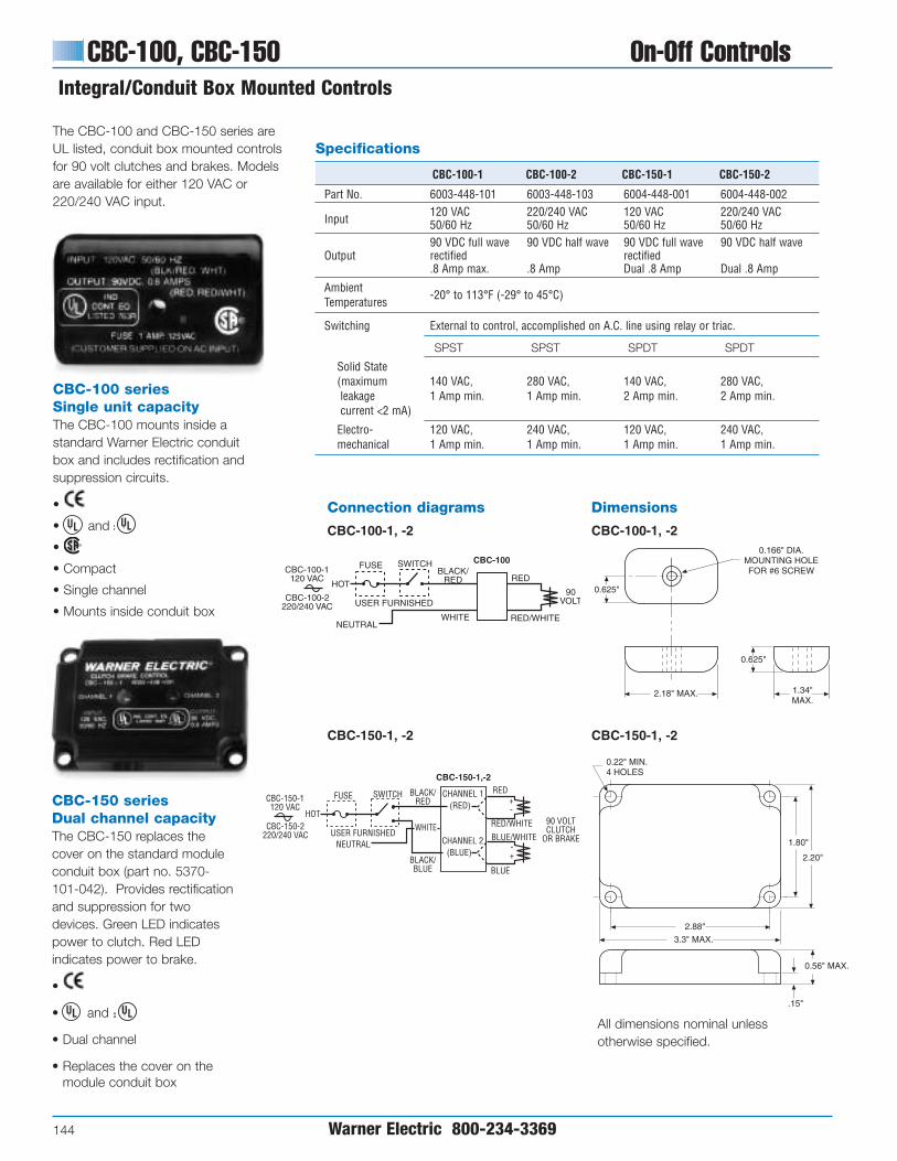
CBC-100, CBC-150 On-Off Controls
144 Warner Electric 800-234-3369
Integral/Conduit Box Mounted Controls
Specifications
CBC-100-1 CBC-100-2 CBC-150-1 CBC-150-2
Part No. 6003-448-101 6003-448-103 6004-448-001 6004-448-002
Input120 VAC 220/240 VAC 120 VAC 220/240 VAC50/60 Hz 50/60 Hz 50/60 Hz 50/60 Hz90 VDC full wave 90 VDC half wave 90 VDC full wave 90 VDC half wave
Output rectified rectified.8 Amp max. .8 Amp Dual .8 Amp Dual .8 Amp
AmbientTemperatures
-20° to 113°F (-29° to 45°C)
Switching External to control, accomplished on A.C. line using relay or triac.
SPST SPST SPDT SPDT
Solid State(maximum 140 VAC, 280 VAC, 140 VAC, 280 VAC, leakage 1 Amp min. 1 Amp min. 2 Amp min. 2 Amp min.current <2 mA)
Electro- 120 VAC, 240 VAC, 120 VAC, 240 VAC, mechanical 1 Amp min. 1 Amp min. 1 Amp min. 1 Amp min.
Connection diagrams
CBC-100-1, -2
CBC-150-1, -2
Dimensions
CBC-100-1, -2
CBC-150-1, -2
All dimensions nominal unlessotherwise specified.
The CBC-100 and CBC-150 series areUL listed, conduit box mounted controlsfor 90 volt clutches and brakes. Modelsare available for either 120 VAC or220/240 VAC input.
FUSE SWITCHBLACK/
REDHOT
CBC-100-1120 VAC
CBC-100-2220/240 VAC
NEUTRAL
USER FURNISHED
WHITE
CBC-100
RED
RED/WHITE
90VOLT
2.18" MAX. 1.34"MAX.
0.625"
0.166" DIA.MOUNTING HOLEFOR #6 SCREW
0.625"
CBC-150-1120 VAC
CBC-150-2220/240 VAC
HOT
FUSE SWITCH BLACK/RED
CBC-150-1,-2RED
NEUTRALUSER FURNISHED
WHITE RED/WHITE
BLACK/BLUE
CHANNEL 1
(BLUE)
BLUE/WHITE
BLUE
CHANNEL 2
(RED)
90 VOLTCLUTCH
OR BRAKE
+-
-+
2.88"
3.3" MAX.
1.80"
2.20"
0.22" MIN.4 HOLES
0.56" MAX.
.15"
CBC-150 series Dual channel capacityThe CBC-150 replaces thecover on the standard moduleconduit box (part no. 5370-101-042). Provides rectificationand suppression for twodevices. Green LED indicatespower to clutch. Red LEDindicates power to brake.
•
• and
• Dual channel
• Replaces the cover on themodule conduit box
CBC-100 seriesSingle unit capacityThe CBC-100 mounts inside astandard Warner Electric conduitbox and includes rectification andsuppression circuits.
•
• and
•
• Compact
• Single channel
• Mounts inside conduit box

On-Off Controls CBC-160
Warner Electric 800-234-3369 145
0.56"
.15"
2.2"
1.8"
0.22" , 4 HOLES
2.88"
3.30"
Integral/Electrically Released Motor Brake Controls
Connection Diagram
Dimensions
All dimensions nominal unless otherwise specified.
•
•
CBC-160-1
90 VDCBRAKE
+
-0 100
50RED
RED/WHITE
460 VAC
•
•
CBC-160-2
230 VAC 90 VDCBRAKE
+
-0 100
50
230 VAC
•
•
CBC-160-2
230 VAC90 VDCBRAKE
+
-0 100
50
460 VAC
•
•
CBC-160-2
230 VAC 90 VDCBRAKE
+
-0 100
50
230 VAC
RED
RED/WHITE
BLACK/RED
WHITE
(MOTOR TERMINALS)
RED
RED/WHITE
•
•
CBC-160-2BLACK/RED
WHITE
230 VAC 90 VDCBRAKE
(MOTOR TERMINALS)
+
-0 100
50T7 T8 T9
T1 T2 T3
T4 T5 T6
T7 T8 T9
T1 T2 T3
T4 T5 T6
T7 T8 T9
T1 T2 T3
T4 T5 T6
T7 T8 T9
T1 T2 T3
T4 T5 T6
RED
RED/WHITE
BLACK/RED
WHITE
(MOTOR TERMINALS)
RED
RED/WHITE
BLACK/RED
WHITE
(MOTOR TERMINALS)
FUSE SWITCHBLACK/
REDHOT120 VAC
NEUTRAL
USER FURNISHED
WHITE
WYE Connected Motor
DELTA Connected Motor
Specifications
CBC-160-1 CBC-160-2
Part No. 6013-448-001 6013-448-002
Input 120 VAC, 50/60 Hz 220/240 VAC, 60 Hz, 1 Phase, 100 VA max.
Status IndicatorRed LED indicates
—power to the brake
OutputSingle Channel, 30-100 VDC half-wave rectified nominal,0.8 Amps maximum
AmbientTemperatures
0° to 122°F (-18° to 50°C)
SwitchingAccomplished through motor starter or on A.C. line using relay or triac
CBC-160
The CBC-160 series clutch/brake controls provide a single 90 VDCadjustable output for use with any clutch/brake unit. The adjustable output will provide consistent and repeatable release for Warner Electric’s 90 VDC permanent magnet electrically released brakes. The CBC-160 mounts as the cover on the standardmodule conduit box (part number: 5370-101-042).
The 160-1 accommodates 120 volts A.C.motors.
•
•
• Adjustable 30-100 VDC
• LED indicator
• 120 volt A.C. input
The power to the 160-2 control can comefrom either a 230 volt or 460 volt A.C.motor. Customer-provided switching is ac-complished through the motor starter onthe A.C. input. This allows convenientretrofit of spring-set style motor brakes andinexpensive installation of new applications.
•
•
• Adjustable 30-100 VDC
• Power from motor
• Easy retrofit
• 230/460 motors

CBC-801 On-Off Controls
146 Warner Electric 800-234-3369
6 5 4 3
7 8 1 2
NEUTRAL
90 V CLUTCH
OCTAL SOCKET120 VAC50/60 Hz
HOT
STOP
START
90 V BRAKE
SWITCH
USER FURNISHED
6 5 4 3
7 8 1 2
NEUTRAL
90 V CLUTCH
OCTAL SOCKET120 VAC50/60 Hz
HOT
90 V BRAKE
SWITCHUSER FURNISHED
+
+
–
–
1.718" ± .031"
1.968" ± .031" SQ.
2.437" ± .062"
STD. OCTAL KEYED PLUG
1.57"(39.9)
2.39"(60.7)
.70"(17.8)
2.40"(61)
.71"(18)
1.57"(39.9)
OCTAL SOCKET
DIN RAIL MOUNT SOCKET
Plug-in Octal Socket Power Supplies
The CBC-801 is a basic on-off powersupply that provides full voltage to a 90volt clutch or brake and is activated by anexternal switch. This type of power supplyis sufficient for many clutch/brakeapplications.
CBC-801 series Multi-unit capacityThe CBC-801 is a plug-in power supplywhich is used with an octal socket. Thewiring connections are made at thesocket. The CBC-801 will operate twounits separately—or simultaneously. Octalsocket is purchased separately. Specifications
CBC-801-1 CBC-801-2
Part No. 6001-448-004 6001-448-006
Input Voltage 120 VAC, 50/60 Hz 220/240 VAC, 50/60 Hz
Output 90 VDC, 1.25 A max.
Circuit Protection Fused 1.6 Amp, 250 V fast-blo
Ambient Temperature
-23° to 116°F (-31° to 47°C)
Max. CycleRate
Limited by the clutch or brake, variable with application
Single pole, double throwSwitching Minimum contact rating: 10 Amp, 28 VDC resistive or 10 Amp, 120 VAC
inductive
Status IndicatorRed LED indicates brake is energized, Green LED indicates clutch isenergized
Two versions of octal socket are available:Mounting 6001-101-001 foot mount
6001-101-002 DIN rail mount
•
•
•
• For basic on-off operation
• Wiring connections made at octalsocket
• Arc suppression circuitry extendsswitch life
• Fused for overload protection
• LED output indicators
• DIN rail mountable
Dimensions
Connection Diagram
All dimensions nominal unless otherwise specified.
Connection diagram for operating clutch/brakeseparately.
Connection diagram for operating clutch/brake simultaneously.

On-Off Controls CBC-802
Warner Electric 800-234-3369 147
Plug-in Octal Socket Power Supplies
CBC-802PLC compatibleThe CBC-802 is a power supply withsolid state circuits for load switching.A brake and clutch may be operatedseparately—or, two brakes or twoclutches, one unit on at a time. The CBC-802 mounts on an octal socket(purchased separately), and the wiringconnections are made at the socketterminals. Octal socket sold separately,refer to mounting specifications for part number.
•
• Plug-in power supply with solid stateswitching circuits—increases switchservice life
• Adjustable time delay for controllingclutch/brake overlap
• Internally fused for overload protection
• DIN rail mountable
• LED output indicators
Specifications
CBC-802
Part No. 6002-448-001
Input 120 VAC, 50/60 Hz
Output 90 VDC, 0.5 A max.
Status Indicator Red LED indicates brake energized. Green LED indicates clutch energized.
Circuit Protection Fused 0.5 Amps, 250 V
Ambient Temperature
-20° to 113°F (-29° to 45°C)
Leakage Current 500 uA max. for solid state switches
Max. Cycle Rate Limited by the clutch or brake, variable with application
Momentary contact, maintained contact, or solid state open collector logicSwitching Minimum contact rating 20 VDC resistive, 0.01 Amps
Minimum input pulse—1 millisecond
AdjustmentsExternally adjusted potentiometer sets overlap between clutch and brake from 0 to 130 MS.
Mounting:Two versions of octal socket are available:6001-101-001 foot mount6001-101-002 DIN rail mount
Dimensions
Connection Diagram
3.562"
3.75"
.062"
STD. OCTAL KEYED PLUG
1.437"
1.57"(39.9)
2.39"(60.7)
.70"(17.8)
2.40"(61)
.71"(18)
1.57"(39.9)
OCTAL SOCKET
DIN RAIL MOUNT SOCKET
NEUTRAL
OCTAL SOCKET
120 VAC50/60 Hz
HOT
SWITCHUSER FURNISHED
ST
OP
5 3
7 8 1 2
90 V BRAKE
90 V CLUTCH
46
All dimensions nominal unless otherwise specified.

CBC-400 On-Off Controls
148 Warner Electric 800-234-3369
Panel Mounted ControlCBC-400 seriesDual channel controlsThe CBC-400 series is a basic on-offcontrol which supplies 24 or 90 VDC for electric clutch/brake operation. They offer optically isolated switching inputs for start, stop, and emergencystop (E-stop). These controls can be setup to operate the two outputs alternately(single) or simultaneously (dual). Refer tothe Appendix for additional setup andswitching information.
•
• 24 or 90 Volt DC output
• Auxiliary 12V supply
• Fast coil suppression
• Single or dual channel operation
• Optically isolated input switching
Specifications
CBC-400-90 CBC-400-24
Part No. 6006-448-003 6006-448-002
Input Voltage 120 VAC 24-30 VAC
Output Voltage 90 VDC 24 VDC
Output Current1 Amp/Channel 5 Amps/Channel2 Amps Total 5 Amps Total
AuxiliarySupply
12 VDC 250 mA
CircuitProtection
Fused 2.5 Amp, 250 V fast-blo Fused 6.3 Amp, 250 V fast-blo
AmbientTemperature
+32° to 122°F (0° to 50°C)
Status Indicators Red LED indicates channel is energized.
Adjustments Jumper for single or dual operation. See appendix for explanation.
Inputs3 Optically isolated, 10-30 VDC, 3-9 mA for Channel 1, Channel 2 and Channel 2 override (applies full voltage to channel 1 output).
Enclosure (Optional)
Dimensions
Connection Diagram
CBC-400WARNER ELECTRIC
POWER/OUTPUT
N/C• • •Single
1
2
3
4
5
6
7
8
NEUTRAL CBC-400-90120 VAC
HOT CBC-400-2424-30 VAC
8
7
6
5
4
3
2
1
Dual
(CHANNEL 2 LED) (CHANNEL 1 LED)
CHANNEL 2(CLUTCH OR BRAKE)
CHANNEL 1(CLUTCH OR BRAKE)
J1
+
-
+
-CHANNEL 1
INPUT(10-30 VDC)
CHANNEL 2INPUT
(10-30 VDC)
AUXILIARYSUPPLY+12 VDC,250 mA
CHANNEL 2OVERRIDE(10-30 VDC)
+
–
+
–
+
–
+
–
SWITCHING
1.75"
0.90"
6.00".20"
3.90"
1.15"
1.25"
1.40"
6.40"
.10" R
All dimensions nominal unless otherwise specified.
• Lift off hinge
• Quick-release latches
• Conforms to NEMA Type 13
• European Standard IEC 529, IP65
Part No. 6042-101-004
Size8"H x 6"W x 4"D(203.2 x 152.4 x 101.6 mm)

On-Off Controls CBC-450
Warner Electric 800-234-3369 149
Specifications
CBC-450-90 CBC-450-24
Part No. 6006-448-006 6006-448-005
Input Voltage 120/220/240/380/480 VAC
Output Voltage 90 VDC 24 VDC
Output Current1 Amp/Channel 4 Amps/Channel1.2 Amps Total 4 Amps Total
AuxiliarySupply
12 VDC 250 mA
CircuitProtection
Fused 1.5 Amp Fused 5 Amp
AmbientTemperature
+32° to 122°F (0° to 50°C)
Status Indicators Red LED indicates channel is energized.
Adjustments Jumper for single or dual operation. See appendix for explanation.
Inputs3 Optically isolated, 10-30 VDC, 3-9 mA for Channel 1, Channel 2 and Channel 2 override (E-stop).
Dimensions
Connection Diagram
CBC-450WARNER ELECTRIC
AC INPUT
CHANNEL 1INPUT
(10-30 VDC)
CHANNEL 2INPUT
(10-30 VDC)
AUXILIARYSUPPLY12 VDC,250 mA
CHANNEL 2OVERRIDE(10-30 VDC)
1
2
3
4
5
6
480VAC380VAC240VAC220VAC120VAC
0 VAC
+
-
+
-
+
-
+
-
1
2
3
4
5
6
7
8
+
-
+
-
8
7
6
5
4
3
2
1
OUTPUTSWITCHING
CONNECT NEUTRALTO TERMINAL 6 AND HOTTO CORRESPONDINGAC INPUT VOLTAGE.
CHANNEL 2(CLUTCH OR BRAKE)
CHANNEL 1(CLUTCH OR BRAKE)
N/C (DO NOT USE)
(CHANNEL 2 LED) (CHANNEL 1 LED)
• • •Single Dual
J1
Enclosure (Optional)
4.60"
2.85"
3.50"
4.72"
4.50"
4.08"3.90"
CBC-450 series Dual channel control with transformer for variable input voltage
The CBC-450 series is a basic on-offcontrol which supplies 24 or 90 VDCfor electric clutch/brake operation. Theyoffer optically isolated switching inputsfor start, stop, and emergency stop (E-stop). These controls can be set up tooperate the two outputs, alternately(single) or simultaneously (dual). Referto the Appendix for additional setupand switching information. The CBC-450 series has a power transformerwhich will operate with a 120, 220,240, 380 or 480 VAC input.
•
• 24 or 90 Volt DC output
• Auxiliary 12V supply
Panel Mounted Control
• Fast coil suppression
• Single or dual channel operation
• Optically isolated switching
• Lift off hinge
• Quick-release latches
• Conforms to NEMA Type 13
• European Standard IEC 529, IP65
Part No. 6006-101-007
Size6"H x 6"W x 6"D(152.4 x 152.4 x 152.4 mm)
All dimensions nominal unless otherwise specified.

150 Warner Electric 800-234-3369
2.75"
4.38"
.56" 5.50"
6.63"
2.75"
.19" DIA.MTG. HOLES (4)
.50"
1.00"
.50" CONDUIT SIZEBOTH SIDES
3.00"
.69"
1
2
3
4
5
6
7
+
-K1K2
120 VAC50/60 Hz
+90V
ADJ. OUTPUT
RHEOSTAT1000Ω50W
6010-101-002(not included)
120 VAC50/60 Hz
1
2
3
4
5
6
7
+90V
+ADJ.VOLTAGE
TORQUE CONTROL
SWITCH
(USER FURNISHED)
(NEUT)
(HOT)
STOP
START
90 VOLT UNIT
90 VOLT UNIT
+ CLUTCH
+ BRAKE
1
2
3
4
5
6
7
+90V
ADJ.VOLTAGE
CLUTCH
ELECTRICALLYRELEASED BRAKE
SWITCH
120 VAC50/60 Hz
(USER FURNISHED)
(NEUT)
(HOT)
Energize K1,Brake releasedEnergize K1 & K2,Softstop BrakeFull Brake On as shown
ELECTRICALLYRELEASEDBRAKE
Specifications
MCS-103-1
Part No. 6010-448-002
Input 120 VAC, 50/60 Hz
1.25 AmpOutput 90 V full wave rectified for one unit and adjustable from
0-90 volts full wave rectified for second unit
Circuit Protection Fused 1.5 Amp, 250 V
Ambient Temperature
-20° to 113°F (-29° to 45°C)
Maximum Cycle Rate Limited by the clutch or brake and will vary with application.
Mounting Mounting centers 5-1/2" wide, 3" high. Knockouts for 1/2" conduit
External Switches Double pole, double throw maintained contact. Minimum contact(User furnished) rating: 10 Amp, 28 VDC resistive or 10 Amp, 120 VAC inductive.
Contact ratings given will operate all Warner Electric brake and clutchunits. However, switches with ratings less than those given may beused with fractional horsepower units provided the rating is equal to orgreater than the coil current.
Adjustable Torque Control
The MCS-103-1 is an enclosed controlcomplete with a cover and mountingprovisions. A brake and clutch may beoperated separately with this control –or up to four units, two at a time. Theexternal wiring is connected to theterminal strip located behind the cover.
•
•
• Can be used with electrically released brakes
Dimensions
Connection Diagrams
All dimensions nominal unless otherwise specified.
Soft Stop for Electrically Released Brake
Normal Clutch/Brake Operation(One unit on at a time)
Clutch/Electrically Released Brake Operation
(Both units on at a time)
• Torque control for one 90 VDC clutch or brake
• Operates up to four units, twoon at a time
• Easy-to-install. Compact. 120 VAC input
• Convenient terminal stripbehind an easy-to-removecover
MCS-103-1 Adjustable Torque Controls
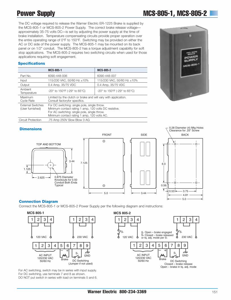
Power Supply MCS-805-1, MCS-805-2
Warner Electric 800-234-3369 151
Connection DiagramConnect the MCS-805-1 or MCS-805-2 Power Supply per the following diagram and instructions:
The DC voltage required to release the Warner Electric ER-1225 Brake is supplied bythe MCS-805-1 or MCS-805-2 Power Supply. The correct brake release voltage—approximately 35-75 volts DC—is set by adjusting the power supply at the time ofbrake installation. Temperature compensating circuits provide proper operation overthe entire operating range of 0°F to 150°F. Switching may be provided on either theAC or DC side of the power supply. The MCS-805-1 may be mounted on its backpanel or on 1/2" conduit. The MCS-805-2 has a torque adjustment capability for softstop applications. The MCS-805-2 requires two switching circuits when used for thoseapplications requiring soft engagement.
MCS 805-1
1 2 3 4
1 2 3 4 5 6 7 8 9
1 2 3 4
120 VAC
MCS 805-2
1 2 3 4
1 2 3 4 5 6 7 8 9
1 2 3 4
120 VAC
AC INPUT120/230 VAC
50/60 Hz
230 VAC 230 VAC
– +
Brake DC Switching(Jumper if not used)
S1
S1 S1
S2
GND AC INPUT120/230 VAC
50/60 Hz
– +
BrakeDC Switching
Closed – brake releaseOpen – brake in tq. adj. mode
S1
GND
S1Open – brake engagedClosed – brake released
or tq. adj. mode per S1
0.28 Diameter (4) Mtg HolesClearance for .25" Screw
BACK
0.875 Diameter Knockouts for 0.50 Conduit Both Ends Typical
TOP AND BOTTOM
3.44
2.625
1.125
FRONT
7.125
5.0
SIDE
3.44
0.56
6.0
4.81
5.0
3.750.53
Dimensions
Specifications
MCS-805-1 MCS-805-2
Part No. 6090-448-006 6090-448-007
Input 115/230 VAC, 50/60 Hz ±10% 115/230 VAC, 50/60 Hz ±10%
Output 0.4 Amp, 35/75 VDC 0.4 Amp, 35/75 VDC
Ambient Temperature
-20° to 150°F (-29° to 65°C) -20° to 150°F (-29° to 65°C)
Maximum Limited by the clutch or brake and will vary with application. Cycle Rate Consult factoryfor specifics.
External Switches For DC switching: single pole, single throw. (User furnished) Minimum contact rating 1 amp, 120 volts DC resistive.
For AC switching: single pole, single throw. Minimum contact rating 1 amp, 120 volts AC.
Circuit Protection .75 Amp 250V Slow Blow 3 AG
For AC switching, switch may be in series with input supply.For DC switching, use terminals 7 and 8 as shown.DO NOT put switch in series with load on terminals 5 and 6.

CBC-200, CBC-300 Adjustable Torque Controls
152 Warner Electric 800-234-3369
1 2 3 4 5 6 7 8 9TB1
120VAC
50/60 Hz
G
H
NOR
G
H
N
CBC-300 ISADJUSTABLE BOTH
CHANNELS.
CBC-200 IS FIXEDVOLTAGE CHANNEL 2
1-1/2 A
CH-1 CH-2
+ - + -
SW1 SW2 ADJUSTABLEVOLTAGE CHANNEL 1
.750" ± .020"(19.1 ± .508)
1.345" ± .020"(34.2 ± .508)
1.750" ±.010"(44.5 ± .254)
2.063"(52.4)NOM.
6.500"(165.1)NOM.
1.183"(46.1)NOM.
2.500"(63.5)NOM. 1.095"
(27.8)REF.
2.250" ± .010"(57.2 ± .254)
5.187" ±
.020"
(131.7 ± .508)
4.460"(113.3)NOM.
.180" (.46) DIA.MTG. HOLE
.620"(15.7)REF.
Specifications
CBC-200 CBC-300
Part No. 6011-448-001 6021-448-001
Input Power 120 VAC +10% -15%, 50/60 Hz, single phase, 215 VA max.
OutputPulse-width modulated full wave rectified D.C. Constant current, switch selectable ranges, 0-90 volt
Ambient +32°F to +113°F (0°C to 45°C) with plastic cover installedTemperature +32°F to +150°F (0°C to 66°C) with plastic cover removed
Internal line to line short circuit protectionCircuitOptional customer supplied fusing on A.C. line, 1.5 Amps, 250 VAC. ProtectionFast-acting fuse recommended
Current Adjust(via front panel Single adjustable channel Dual adjustable channelspotentiometers)
“POWER”—green LED indicates A.C. power is applied to the Status control. “SHORT”—red LED indicates a short circuit condition exists on one indicatorsor both outputs.
Set DIP switches SW1 and SW2 to suit the current draw of the connected
Internalconnected clutch/brake coil:
AdjustmentsSwitch Range 1 2 3 4 5Max CurrentDraw (mA) 60 175 245 305 533
Mechanical or electromechanical—customer supplied:External 1 Amp, 125 V minimum ratingSwitching Solid-state, NPN isolated transistor—customer supplied:
2 Amp, J250 V minimum rating. Maximum off state leakage current <1 mA
Dimensions
Connection Diagram
The CBC-200 and CBC-300 Controlsprovide single/dual torque control whenconnected to any of Warner Electric’s90 volt clutches and brakes.
Common features
• and
• Current monitored output maintainsconsistent torque regardless ofvariation in coil temperature.
• Switch selection tunes control toexactly match power requirementsand operating characteristics of eachclutch or brake.
• Individual torque adjust allows presetmaximum torque tailored to applica-tion requirements.
• Short circuit protection, line to line.
• Torque limiting protects machinecomponents from damage.
• Can be used with electrically releasedbrakes.
CBC-200Dual channel/Single channeltorque adjustThe CBC-200 is a dual channel controlwith one adjustable current and one fixed voltage.
CBC-300Dual channel/Dual channeltorque adjustThe CBC-300 has two adjustable current channels.
Single or Dual Channel Adjustable Torque Control

Adjustable Torque Controls CBC-500
Warner Electric 800-234-3369 153
CHANNEL 2 OVERRIDE INPUT(10-30 VDC)
CBC-500WARNER ELECTRIC
POWER/OUTPUT
CHANNEL 1 INPUT(10-30 VDC)
CHANNEL 2 INPUT(10-30 VDC)
AUXILIARYSUPPLY
12 VDC, 250 mA
SWITCHING
+
-
+
-
+
-
+
-
1
2
3
4
5
6
7
8
CHANNEL 2(CLUTCH ORBRAKE)
8
7
6
5
4
3
2
1
CHANNEL 1(CLUTCH ORBRAKE)
+
-
+
-
N/C (DO NOT USE)
CBC-500-90120 VAC
CBC-500-2424-30 VAC
DualSingle
(CHANNEL 2 LED) (CHANNEL 1 LED)
J2J1
(CHANNEL 1ADJUST)
(CHANNEL 2ADJUST)
FREQUENCYADJUST
• • • •
• • • •1.75"
0.90"
6.00"0.20"
3.90"
1.15"1.40"
6.40"
Panel MountedCBC-500 seriesDual torque adjustable power suppliesThe CBC-500 series is a dual channel adjustable voltage control with opticallyisolated input switching for 24 and 90volt electric clutches and brakes. Thesecontrols can be set up to energize thetwo outputs alternately (single) or simulta-neously (dual). Refer to the Appendix foradditional setup and switching information.
•
• Dual adjustable channels
• Optically isolated input switching
• Single or dual channel operation
• Auxiliary 12V supply
• Can be used with electrically released brakes
• Lift off hinge
• Quick-release latches
• Conforms to NEMA Type 13
• European Standard IEC 529, IP65
Part No. 6042-101-004
Size8"H x 6"W x 4"D(203.2 x 152.4 x 101.6 mm)
Connection Diagram
Dimensions
Enclosure (Optional)
All dimensions nominal unless otherwise specified.
Specifications
CBC-500-90 CBC-500-24
Part No. 6024-448-003 6024-448-002
Input Voltage 120 VAC 24-30 VAC
Output Voltage 0-90 VDC 0-24 VDC
Output Current1 Amp/Channel 5 Amps/Channel2 Amps Total 5 Amps Total
AuxiliarySupply
12 VDC 250 mA 12 VDC 250 mA
Circuit Fused FusedProtection 2.5 Amp, 250 V Fast-blo 6.3 Amp, 250 V Fast-blo
Ambient Temperature
+32° to 122°F (0° to 50°C)
StatusIndicators
Red LED indicates channel is energized.
Two potentiometers for voltage adjustment of channel 1 and channel 2 output
Adjustmentsfrom 0 to full rated voltage. Frequency adjustment from 60 to 400 Hz to reduce clutch/brake “Hum” associated with machine frequencies. Jumper for single or dual operation. See appendix for explanation.
Inputs:3 Optically coupled, 10-30 VDC, 3-9 mA for Channel 1, Channel 2 and Channel 2 override (applies full voltage to channel 1 output)

CBC-550 Adjustable Torque Controls
154 Warner Electric 800-234-3369
Panel Mounted
Specifications
CBC-550-90 CBC-550-24
Part No. 6024-448-006 6024-448-005
Input Voltage 120/220/240/380/480 VAC
Output Voltage 0-90 VDC 0-24 VDC
Output Current1 Amp/Channel 4 Amps/Channel1.2 Amps Total 4 Amps Total
AuxiliarySupply
12 VDC 250 mA 12 VDC 250 mA
Circuit Fused FusedProtection 1.5 Amp, 250 V fast-blo 5 Amp, 250 V fast-blo
Ambient Temperature
+32° to 122°F (0° to 50°C)
StatusIndicators
Red LED indicates channel is energized.
Two potentiometers for voltage adjustment of channel 1 and channel 2 output
Adjustmentsfrom 0 to full rated voltage. Frequency adjustment from 60 to 400 Hz to reduce clutch/brake “Hum” associated with machine frequencies. Jumper for single or dual operation. See appendix for explanation.
Inputs3 Optically coupled, 10-30 VDC, 3-9 mA for Channel 1, Channel 2 and Channel 2 override (applies full voltage to channel 1 output)
Enclosure (Optional)
• Lift off hinge
• Quick-release latches
• Conforms to NEMA Type 13
• European Standard IEC 529, IP65
Part No. 6006-101-007
Size6"H x 6"W x 6"D(152.4 x 152.4 x 152.4 mm)
CBC-550 series Dual adjustable with power transformer
The CBC-550 series is a dual channel ad-justable voltage control with opticallycoupled switching for 24 and 90 volt electricclutches and brakes. These controls can beset up to energize the two outputs alter-nately (single) or simultaneously (dual). Referto the Appendix for additional setup andswitching information.
The CBC-550 series has a powertransformer which will operate with a 120,220, 240, 380, or 480 VAC input.
•
• Dual adjustable channels
• Optically isolated input switching
• Single or dual channel operation
• Can be used with electrically released brakes

Adjustable Torque Controls CBC-550
Warner Electric 800-234-3369 155
CBC-550WARNER ELECTRIC
AC INPUT
CHANNEL 1INPUT
(10-30 VDC)
CHANNEL 2INPUT
(10-30 VDC)
AUXILIARYSUPPLY12 VDC,250 mA
CHANNEL 2OVERRIDE(10-30 VDC)
1
2
3
4
5
6
480VAC
380VAC
240VAC
220VAC
120VAC
0 VAC
+
-
+
-
+
-
+
-
1
2
3
4
5
6
7
8
+
-
+
-
8
7
6
5
4
3
2
1
OUTPUTSWITCHING
CONNECT NEUTRALTO TERMINAL 6 AND HOTTO CORRESPONDINGAC INPUT VOLTAGE.
CHANNEL 2(CLUTCH OR BRAKE)
CHANNEL 1(CLUTCH OR BRAKE)
N/C (DO NOT USE)
Dual
Single
(CHANNEL 2 LED) (CHANNEL 1 LED)
J2
J1
(CHANNEL 1ADJUST)
(CHANNEL 2ADJUST)
FREQUENCYADJUST
• • • •
• • • •
4.60"
2.85"
3.50"
4.72"4.50"
4.08"3.90"
Dimensions
Connection Diagram
Panel Mounted
All dimensions nominal unless otherwise specified.

CBC-1825R Adjustable Torque Controls
156 Warner Electric 800-234-3369
Initial PulseAdjustment
Ramp TimeAdjustment
Hold LevelAdjustment
TorqueAdjustment
Time
Cur
rent
Specifications
CBC-1825R
Part No. 1825-448-001
Input Voltage 120 VAC, 50/60 Hz, 100 VA maximum
Output CurrentCurrent driven PWM, compatible with 90 VDC clutch/brake(switch selectable current output)
Auxiliary Supply 12 VDC 250 mA
Circuit ProtectionInput Fused 1.5 Amp, 250 V fast-bloclutch and brake outputs are short circuit protected
Status IndicatorsClutch and brake LEDs indicate output is energizedShort circuit LED indicates a fault
Ambient Temperature 0° to 122°F (-18° to 50°C)
Contact rating: 15 mA @ 15 V, open collector NPN 2mA Switching maximum allowable leakage current and 2 V maximum
saturation voltage
Panel Mounted
Set-up
CBC-1825R seriesThe CBC-1825R is designed to provide consistent and repeatableacceleration and deceleration when used with Warner Electric 90VDC clutches and brakes. Current to each channel is introducedalong an adjustable time ramp and monitored continuously.Adjustments include initial pull-in pulse, hold level, maximumtorque, and ramp time. LEDs are provided on the circuit board toindicate power is applied to the clutch or brake unit.
Note: It is recommended that the auto-gap springs be removed from theclutch and brake for successful accel-decel application.
All dimensions nominal unlessotherwise specified.

Adjustable Torque Controls CBC-1825R
Warner Electric 800-234-3369 157
CLUTCHSWITCH
+12 VDC
HOLD LEVEL SET-UP SWITCH(Up: Normal, Down: Set-Up)
CLUTCH LED
BRAKE LED
SHORT CIRCUIT LED
OPEN:CLUTCHCLOSEDBRAKE
BRAKE
CLUTCH
120 VAC
SELECT
OUTPUTINHIBIT
COMMON
4
3
2
17
6
5
4
3
2
1
CLUTCHINITIALPULSE
CLUTCHRAMPTIME
CLUTCHHOLD
LEVELCLUTCHTORQUEADJUSTBRAKERAMPTIME
BRAKEHOLD
LEVELBRAKE
TORQUEADJUSTBRAKEINITIALPULSE
FUSE
FRONT VIEW
BACK VIEWTOP VIEW
4.25"(108)
5.00"(127)
6.50"(165)
5.00"(127)
5.00"(127)
0.31" TYP.(7.9)
0.15"R TYP.(3.8)
0.25"(6.4)
4.50"(114)
0.75"(19)
Panel Mounted
Connection Diagram
Dimensions

158 Warner Electric 800-234-3369
General Purpose OEX Control
Specifications
CBC-700-90 CBC-700-24
Part No. 6042-448-003 6042-448-002
Input 120 VAC, 50/60 Hz 24-28 VAC, 50/60 Hz
Output VoltagesSteady State 90 VDC 24 VDCOverexcitation 340 VDC 105 VDC
Output Current(Per channel .5 Amps 3.5 Ampsalternately)
OEX Pulse Adjustable through logic board dip switchesDuration (see service manual)
Inputs Two-optically isolated (10-30 VDC)
AmbientTemperature 0°F to 140°F (-18°C to +60°C)Range
Maximum OffState Leakage
<2 mA (inputs)
CircuitProtection
2.5A Slo-Blo (5 x 20 mm) 5A Slo-Blo (5 x 20 mm)
Auxiliary Supply 12 VDC, 250 mA maximum
Enclosure (Optional)
• Lift off hinge
• Quick-release latches
• Conforms to NEMA Type 13
• European Standard IEC 529, IP65
Part No. 6042-101-004
Size8"H x 6"W x 4"D(203.2 x 152.4 x 101.6 mm)
CBC-700 seriesSimple, compact, high performance OEXcontrol for either 90 or 24 VDC clutchesand brakes. OEX spike duration and anti-overlap times delay are adjustable.Two optically isolated inputs.
• • High performance• Switch selectable OEX duration• Force decay suppression with
adjustable anti-overlap time delay• Compact, flexible mounting• Models for 24 or 90 volt clutches
and brakes• Cycle rate limited by clutch/brake
CBC-700 Overexcitation Controls

Overexcitation Controls CBC-700
Warner Electric 800-234-3369 159
1
2
3
4
5
6
7
8
9
10
11
120 VAC50/60 Hz
SW
BK
CL
CR
CR, SW user furnished switchoptions for use with control.
normally open relay contact normally open push button switch
NOTE:
CRSW
TYPICAL 3 WIRESWITCHING
CONFIGURATION
HOT
NEUTRAL
+
–
+
–
+
–
AUXILIARYSUPPLY
(+12V)
BRAKE INPUT(10-30VDC)
CLUTCH INPUT(10-30VDC)
5.00" (12.70)
3.25"(82.5)
4.65"(118.1)
.95" (24.1)
.50" (12.7)
.125" (3.2)RTYP.
.50" (12.7)
General Purpose OEX Control
Dimensions
Connection Diagram
All dimensions nominal unless otherwise specified.

CBC-750 Overexcitation Controls
160 Warner Electric 800-234-3369
Rapid Acceleration/Deceleration
Specifications
CBC-750-6 CBC-750-24 CBC-750-90
Part No. 6041-448-001 6041-448-002 6041-448-003
Input Power 120/220/240 VAC, ±10%, 50/60 Hz, 350 VA (switch selectable)
Opto-isolated 10-30 VDC @ 10-35 mA nominal sinking or sourcing, or Control Inputs 24 VAC (50/60Hz) @ 22 mA nominal, or
120 VAC (50/60 Hz) @ 20 mA nominal
Clutch/brake OutputSteady State OutputCurrent controlled .910 to 4.34 A max. .227 to 1.175 A max. .060-.310 A max.Current Rise Time Dependent on clutch/brake sizeCurrent Fall Time Depending on clutch/brake sizeOverexcitation Voltage 75 VDC nom. 240 VDC nom. 450 VDC nom.Overexcitation Time Automatic adjustment by control feedbackAnti-overlap Time Automatic adjustment by control feedback
Power Supply Output 12 VDC, ±0.6 VDC, 250 mA max.
Auxiliary Indicator Opto-isolated NPN transistorsOutputs 24 VDC maximum, 20 mA max., reverse polarity protected
Circuit Protection Internal short circuit protection on each output channel.
FusingAC Input Line 2 Amp, 250 V Slo-BloOEX Supply 10 Amp, 32 V Slo-Blo 5 Amp, 250 V Slo-Blo 1 Amp, 250 V Slo-Blo
•
• High performance OEX control
• Constant current output capability
• Models for 6, 24, and 90 V clutches and brakes
• Outputs short circuit protected.
• AC/DC optically isolated inputs
• Transformer isolationRemote torque potentiometer capability
• Input/Output inhibit functions
• Switch selectable OEX function
• Automatic CH1/CH2 anit-overlapfeature
• Heavy duty suppression circuits
• Selectable output current ranges
• Remote status indicators inputs and outputs
CBC-750 seriesDual channel, current basedOEX with switching logicWarner Electric’s CBC-750 series ofConstant Current OverexcitationClutch/Brake Controls are solid-stateelectronic controls designed to increasethe cycle rate capabilities and accuraciesof electromagnetic clutches and brakes.The controls accomplish this by sending amomentary high voltage overexcitationspike to the clutch and/or brake magneticcoil to build a high density magnetic fluxfield almost instantaneously. By usingoverexcitation, the response time isreduced as dramatically as performanceis increased. For example, the currentbuild up time of a 5 inch, 6 volt magnet isreduced from 84 milliseconds to 2milliseconds.
The CBC-750 user selects either 120,220 or 240 VAC operation at the time ofinstallation. Models for 6 volt, 24 volt, or90 volt clutches and brakes are available.
LED indicators on the faceplate of eachcontrol tell the user the status of inputsignals, output activation and any auxiliaryinputs. A reset switch resets the outputshould a short be detected. Remotetorque adjust potentiometer inputs arealso provided. Appropriate current rangefor each size clutch or brake is selectedby a dip switch. Constant current foreach level is assured by the control’sdesign.
• Maintains torque at preset levelsregardless of temperature variations
• Automatically controls OEX pulseduration for optimum response withoutoverheating coils
• Automatically prevents clutch and brake“overlap”
• Configurable as an analog followercontrol through remote top input
• Integral switching logic through auxiliary,inhibit and override inputs
Shown with optional
cover, part number
6041-101-004

Overexcitation Controls CBC-750
Warner Electric 800-234-3369 161
1
2
3
4
5
6
7
120/220/240 VAC50/60 Hz
CHANNEL 1(CLUTCH OR BRAKE)
CHANNEL 2(CLUTCH OR BRAKE)
CR
Minimum Connection Diagram using DC inputs.
1
2
3
4
5
6
7
TB1COMMONCONNECTIONS
TB2
10-30 VDC CONNECTION
1
2
3
4
5
6
7
8
TB5Q
1
2
3
4
5
6
7
TB6
Q, CR user furnished switchoptions for use with control.
NPN transistor normally open relay contact
NOTE:
QCR
AUXILIARYSUPPLY12 VDC
CHANNEL1OPTIONALREMOTETORQUEPOTENTIOMETER
CHANNEL 2OPTIONALREMOTETORQUEPOTENTIOMETER
+
-
SW8
SW6
SW10
SW3 SW11
SW5
SW2
SW4
SW7
SW5Channel 1 OEXenable ( ) / disable ( )
SW2Channel 1 local ( )or remote ( )torque adjust
SW4Channel 2 local ( )or remote ( )torque adjust
SW11Auxiliary input selectorChannel 1 ( )Channel 2 ( )
SW6Channel 2 OEXenable ( )disable ( )
SW10Channel 1 input invert ( ) ( )
SW3Level/pulse selector level ( )pulse ( )
SW8Channel 2 current range selector(settings in diagram below)
SW7Channel 1 current range selector(settings in diagram below)
All switches are in the down ( ) position from factory
Channel 1Torque Adjust(0-Full Voltage)
Channel 2Torque Adjust(0-Full Voltage)
5.69" (144.53)
14.01" (355.85)
13.00" (330.20)
11.50" (292.10)
7.50"(190.50)
9.56"(242.82)
9.77"(244.16)
4.78"(121.41)
10.75"(273.05)
3.09"(78.49)
1.12" (28.45) DIA.
1.25" (31.75)
2.69"(68.33)
.88" (22.35) DIA.CONDUIT ENTRANCE (3)
3.16"(80.26)
3.00"(76.20)
.218" (5.54) DIA.MTG. HOLES (4)
Rapid Acceleration/Deceleration
Dimensions
Connection Diagram
Setup SwitchesSW1: AC Voltage selection switch on
terminal board inside control unit
Max. Current Output
(SW7 & SW8 settings)
NominalVoltage 1 2 3 4 5
6 0.910 2.35 3.183 3.760 4.34024 0.227 0.641 0.881 0.940 1.175
90 0.060 0.176 0.256 0.282 0.310
Seven optically isolated inputs accept 10-30V A.C./D.C. (TB2) or 120 VAC (TB3),configured through set-up switches
1. Channel 2 Input
2. Channel 2 Input Inhibit(disregards channel 2 input signal)
3. Auxiliary Input
4. Channel 1 Input
5. Channel 1 Input Inhibit(disregards channel 1 input signal)
6. Output Inhibit(deactivates both output channels)
7. Channel 2 Override(applies full voltage to channel 1output)
All dimensions nominal unless otherwise specified.

CBC-1000 Closed Loop Position Control
162 Warner Electric 800-234-3369
CBC-1000Position-loop control with errorcorrection compensationWarner Electric’s CBC-1000 is a closed-loop positioning control with errorcompensation designed for industrialclutch/brake applications. The positionloop is closed through encoder feedbackwhich generates pulses proportional toload motion. The CBC-1000 uses thisfeedback to determine the optimumbrake actuation point. The control can beprogrammed to operate in one of twodistinct modes: absolute or incremental.The CBC-1000 includes eight solid statecontrol outputs, a batch counter and aserial communications interface.
The CBC-1000 system consists of fourkey elements: the CBC-1000, aclutch/brake, a clutch/brake control, andan encoder. Nearly any electricclutch/brake size and configuration canbe used. The clutch/brake control shouldhave solid-state compatibility. Simple on-off, soft start/stop, and overexcitationcontrols may all be utilized based on thedesired velocity profile.
System Accuracy
Specifications
Part No. 6060-448-001
Input Power 100 to 130 VAC, 50/60 Hz, 20VA (200 to 260 VAC selectable)
Auxiliary Supply 12 VDC @ 175 mA Used for powering encoder, etc.
Main CounterRange 6 DecadesReset Input External and front panelCount Rate (20 kHz external input frequency)
Batch CounterRange 6 DecadesReset Through front panel only
Signal A and B InputsInput Frequency D.C., 20 kHz quadrature max.Input High Level 3.25 VDC min.Input Low Level 1.75 VDC max.
Control InputsInput Frequency D.C. to 20 Hz max. each inputInput Type Single ended, current sinkingInput Logic Both Edge and Level sensitive as defined by input useInput High Level 10 VDC min. to 20 VDC max.Input Low Level 0 VDC min. to 2 VDC max.Input Current 2.5 mA steady state
DisplayDecades 7 Decade, 0.6" red LEDDecimal Point User programmable
Range: xxx.xxx to xxxxxx
Program Security Program LOCK of lines 1 - 33
Control OutputsType 8 Solid State 100 mA sink max., 24 VDC max.
Serial InterfaceType RS-422A/485 compatibleBaud Rate Selectable: 300, 600, 1200, 2400Parity Selectable: None, Odd, EvenData ASCII
Diagnostics Nine Self-Test Diagnostics
MechanicalEnclosure Aluminum extrusion with molded VALOX bezel.Weight 2.5 lbs.
EnvironmentalOperating Temp. 0° to +50°C (32° to 122°F)Storage Temp. -18° to 85°C (0° to 186°F)Ambient Humidity 90% and noncondensing
Accessories
Description Part Number
Encoder Cable (Accessory) 6060-101-001100 PPR Encoder w/10' cable 6060-101-010250 PPR Encoder w/10' cable 6060-101-025600 PPR Encoder w/10' cable 6060-101-0601200 PPR Encoder w/10' cable 6060-101-1202500 PPR Encoder w/10' cable 6060-101-2505000 PPR Encoder w/10' cable 6060-101-500
(PPR–Pulse Per Revolution)
Serial Interface Module
Performs the necessary voltage levelconversions to interface the RS-422A/485output of the CBC-1000 to RS-232Cequipment.
Part Number: 6060-101-232

OperationSuccessful operation will require knowledge of the following definitions and theirrelationships to the timing diagram.
Function Key Definitions
Count The actual move distance, in pulses or scaled into engineering units (inches, feet,rotations, degrees, etc.) displayed dynamically.
Move The desired move distance in pulses or scaled into engineering units. This isPresent the value the opooerator enters to selecet a new move distance.
Early A distance prior to Move Preset at which the early warning output is activated. Warning Expressed as pulses or engineering units, this output can be used to accomplish
a soft brake (slow down), energize valves, etc.
Batch A cumulative batch counter that can be dynamically displayed to show thenumber of operations, cycles, etc. When this counter reaches the valueprogrammed by the Batch Preset (key 7) the Batch Complete Output isactivated. The batch counter can be manually or automatically reset.
Batch A programmable batch counteractivates the batch complete output when the Preset value programmed has been reached by the batch (key 6)
Braking The actual distance required to stop. This value is dynamically updated toDistance determine the brake actuation point. Factory default is 25 pulses or engineering
units which is only used for the first cycle after power-up. After the first cycle thjeCBC-1000 will tune to the particular brake being utilized. The amount of cyclesneeded for tuning depends on how far the true braking distance value is from thedefault of 25.
Closed Loop Position Control CBC-1000
Warner Electric 800-234-3369 163
CBC-1000 Application Procedure
1COUNT
2MOV PST
3E.W.
6BATCH
7BCH PST
8BRK DIS
Timing Diagram
Inputs:(Active Low)
Outputs:(Momentary)(Edge Triggered)
Start
Stop
Velocity(Speed)
Time(Count)
BrakingDistance
Brake OnPoint
Early WarningPoint
StartPoint
Start
Early Warning
Brake On
Zero Speed
Zero Speed + Delay Time 1
Zero Speed + Delay Time 2
Auxiliary Start
Batch Complete 10
10
10
10 Delay Time 1
Delay Time 2
10
10
10
10
10
10
1. Select the proper clutch/brake• Determine torque and inertia
requirements
• Calculate heat dissipation for requiredcycle rate
• For best accuracy, mountclutch/brake directly on nip or driveshaft; avoid backlash
2. Select quadrature encoder• Select encoder PPR for desired
system resolution (i.e. inches/pulse,degrees/pulse, etc.)
• Determine input frequency; do notexceed 20,000 pulses/sec.
• Mount encoder directly to nip or driveshaft for best accuracy
3. Select clutch/brake power supply• Use CBC-700 overexcitation control
for best accuracy
• Use CBC-500/550 for soft startingand/or stopping
• Brake autogap may have to beremoved for best accuracy
4. Plan system logic (switchingrequirements)• Use absolute mode for indexing
applications such as conveyors andturntables or cutoff applicationswhere close registration is required
• Use incremental mode for cutoffapplications
• Determine switching and relaysrequired for machine operation
5. Select serial interface moduleif applicable.
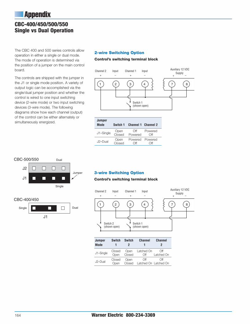
Appendix
164 Warner Electric 800-234-3369
CBC-400/450/500/550 Single vs Dual Operation
3-wire Switching Option
Control’s switching terminal block
Jumper Switch Switch Channel ChannelMode 1 2 1 2
J1–SingleClosed Open Latched On OffOpen Closed Off Latched On
J2–DualClosed Open Off OffOpen Closed Latched On Latched On
2-wire Switching Option
Control’s switching terminal block
Jumper Mode Switch 1 Channel 1 Channel 2
J1–SingleOpen Off Powered
Closed Powered Off
J2–DualOpen Powered Powered
Closed Off Off
The CBC 400 and 500 series controls allowoperation in either a single or dual mode.The mode of operation is determined viathe position of a jumper on the main controlboard.
The controls are shipped with the jumper inthe J1 or single mode position. A variety ofoutput logic can be accomplished via thesingle/dual jumper position and whether thecontrol is wired to one input switchingdevice (2-wire mode) or two input switchingdevices (3-wire mode). The followingdiagrams show how each channel (output)of the control can be either alternately or simultaneously energized.
J2
J1
Dual
Jumper
Single
J1
DualSingle
CBC-400/450
CBC-500/550
Channel 2 Input Channel 1 Input + – + –
Switch 1(shown open)
Auxiliary 12 VDCSupply
+ –
1 2 3 4 7 8
Channel 2 Input Channel 1 Input + – + –
Switch 1(shown open)
Switch 2(shown open)
Auxiliary 12 VDCSupply
+ –
1 2 3 4 7 8

Questions and Answers
Warner Electric 800-234-3369 165
1. What transformers can be used with controlsrequiring 24-30 VAC input?
Part Manufacturer Number Primary Secondary
Abbott 6B 12-160 115 VAC 24V @ 6 amps
Quality 6-K-119VBR 115/230 VAC 24V @ 8 amps
Signal 24-6 115 VAC 24V @ 6 amps
Signal DP24-6 115/230 VAC 24V @ 6 amps
Triad F-260-U 115 VAC 24V @ 6 amps
2. When a single clutch or brake is used with a CBC-200 and no switch is used, a jumper wireis required across terminals 5 & 6 to get outputat terminals 4 & 5.
3. What is the difference between a MCS-801 and a CBC-801-1 or between a MCS-103 and a MCS-103-1?
There is no performance difference between the MCS-103 and MCS-103-1. There is no performancedifference between the MCS-801 and CBC-801-1. TheCBC-801-1 is roughly 1/4” shorter than the MCS-801. Theunits wire and work exactly the same.
4. Which power supplies can be used with the SF 1525HT and SFC 1525HT coil?
The SF and SFC 1525 High Torque clutch coils require .794amps of current to provide full rated torque. The followingpower supplies and controls will provide the needed power.
CBC-100 .8 amps CBC-450 1 ampCBC-150 .8 amps MCS-103-1 1.25 ampsCBC-801 1.25 amps CBC-500 1 ampCBC-400 1 amp CBC-550 1 amp
5. Can I use a CBC-160 with a variable frequencydrive and AC motor?
No. As the voltage to the drive is varied, the output to theelectrically released brake would also vary. This would causethe brake to re-engage when it should be released.
6. Which power supplies offer a 12 VDC power sourcethat could be used to power auxiliary switch inputssuch as inductive or photoelectric sensors?
CBC-400, CBC-450, CBC-500, CBC-550, CBC-700, CBC-750
7. Is the CBC-1000 a stand-alone control?
No. The CBC-1000 provides closed loop feedback for aclutch/brake system. A common system will consist of fourcomponents:
• a Warner Electric brake and clutch• a Warner Electric power supply• an Encoder• a CBC-1000 position control
The application criteria will determine which clutch/brake andwhich control will be appropriate selections.
8. Which of the controls would allow for the independent operation of two clutches or two brakes?
Four controls allow for completely independent operation oftwo clutches or brakes. That is, that a clutch and brake canboth be on at once, both off at once, or one on and one off.These controls are:
CBC-801-1 and CBC-801-2, MCS-103-1,CBC-200, CBC-300
The CBC-400/450 and CBC-500/550 allow for operation ofboth channels on at once, both channels off at once orcycling between channel one and two. However, in the both-on/both-off mode, you cannot also do independent singlechannel operation.
9. Are there any controls that can be used to controlthe torque of a 90 volt clutch or brake via an analog signal input?
Not currently. However, the TCS-200 and TCS-200-1 bothprovide signal following capabilities for use with units with 24volt coils. These units can follow a 0–10 volt or 4–24 mainput signal.
10. Which controls can be used with electricallyreleased brakes?
The CBC-160-1 and CBC-160-2 are designed specifically touse with the conduit box of EM and EUM electricallyreleased brake designs. The CBC-160-1 and CBC-160-2can also be used with ER and FB brake designs.
The MCS-103-1, CBC-200, CBC-300 and CBC-500/550can all be used with ER, FB as well as UM-FBC, EM andEUM-FBB and EM and EUM-MBFB designs.
The MCS 805-1 and MCS 805-2 are for use only with theER 1225 brakes. The ERS series brakes can be used withthe CBC-100 or CBC-801 power supplies.
coil
jumper wire
4 5 6

Ordering Information
166 Warner Electric 800-234-3369
Model Part Number PageCBC-100-1 ..................................................................6003-448-101 ....................144CBC-100-2 ..................................................................6003-448-103 ....................144MCS-103-1 ..................................................................6010-448-002 ....................150CBC-150-1 ..................................................................6004-448-001 ....................144CBC-150-2 ..................................................................6004-448-002 ....................144CBC-160-1 ..................................................................6013-448-001 ....................145CBC-160-2 ..................................................................6013-448-002 ....................145CBC-200 ......................................................................6011-448-001 ....................152CBC-300 ......................................................................6021-448-001 ....................152CBC-400-24 ................................................................6006-448-002 ....................148CBC-400-90 ................................................................6006-448-003 ....................148CBC-450-24 ................................................................6006-448-005 ....................149CBC-450-90 ................................................................6006-448-006 ....................149CBC-500-24 ................................................................6024-448-002 ....................153CBC-500-90 ................................................................6024-448-003 ....................153CBC-550-24 ................................................................6024-448-005 ....................154CBC-550-90 ................................................................6024-448-006 ....................154CBC-1825R ..................................................................1825-448-001 ....................156CBC-700-24 ................................................................6042-448-002 ....................158 CBC-700-90 ................................................................6042-448-003 ....................158CBC-750-6 ..................................................................6041-448-001 ....................160CBC-750-24 ................................................................6041-448-002 ....................160CBC-750-90 ................................................................6041-448-003 ....................160CBC-801-1 ..................................................................6001-448-004 ....................146CBC-801-2 ..................................................................6001-448-006 ....................146Octal Socket, Foot Mount ............................................6001-101-001 ..............146,147Octal Socket, DIN Rail Mount........................................6001-101-002 ..............146,147CBC-802 ......................................................................6002-448-001 ....................147CBC-1000 ....................................................................6060-448-001 ....................162Serial Interface Module..................................................6060-101-232 ....................162Encoders: Cable (Accessory) ........................................6090-101-001 ....................162
100 PPR ......................................................6060-101-010 ....................162250 PPR ......................................................6060-101-025 ....................162600 PPR ......................................................6060-101-060 ....................1621200 PPR ....................................................6060-101-120 ....................1622500PPR ....................................................6060-101-250 ....................1625000PPR ....................................................6060-101-500 ....................162
Optional Enclosure: CBC-400, CBC-500, CBC-700 ....6042-101-004......148, 153,158Optional Enclosure CBC-450, CBC-550 ......................6006-101-007 ............149, 154MCS-805-1 ..................................................................6090-448-006 ....................151MCS-805-2 ..................................................................6090-448-007 ....................151

Service Parts
Warner Electric 800-234-3369 167
Packaged Performance Products Service PartsContents
C-face Compatible Units
Electro Modules
EM Series Modular Clutches, Brakes and Motor Brakes . . . . . . . . . . . . . . . . . . . . 169
UniModules
UM Series Clutch and Clutch/Brake Combinations . . . . . . . . . . . . . . . . . . . . . . . . 176
UM-C Series Ceramic Faced Clutch/Brakes . . . . . . . . . . . . . . . . . . . . . . . . . . . . . N/A
Enclosed UniModules
EUM Series Clutch and Clutch/Brake Combinations . . . . . . . . . . . . . . . . . . . . . . . 184
EUM-W Series Washdown Clutch/Brakes. . . . . . . . . . . . . . . . . . . . . . . . . . . . . . . 184
Shaft and Base Mounted Units
Electro Clutches and Brakes
EC Series Shaft Mounted Clutches . . . . . . . . . . . . . . . . . . . . . . . . . . . . . . . . . . . . 190
EB Series Shaft Mounted Brakes . . . . . . . . . . . . . . . . . . . . . . . . . . . . . . . . . . . . . 196Advanced Technology Clutches and Brakes
ATC Series Clutches . . . . . . . . . . . . . . . . . . . . . . . . . . . . . . . . . . . . . . . . . . . . . . . 202
ATB Series Brakes . . . . . . . . . . . . . . . . . . . . . . . . . . . . . . . . . . . . . . . . . . . . . . . . 204
Packaged Stationary Field Clutches
SFP Clutches . . . . . . . . . . . . . . . . . . . . . . . . . . . . . . . . . . . . . . . . . . . . . . . . . . . . N/A
Electro Pack
EP Series Base Mounted Clutch/Brakes . . . . . . . . . . . . . . . . . . . . . . . . . . . . . . . . 206
EP-C Series Ceramic Faced Base Mounted Clutch/Brakes. . . . . . . . . . . . . . . . . . N/A
Electrically Released Brakes
Spring-Set Brakes
ERS Series Static Engaged Brakes . . . . . . . . . . . . . . . . . . . . . . . . . . . . . . . . . . . . N/A
ERD Series Dual Purpose Engagement Brakes. . . . . . . . . . . . . . . . . . . . . . . . . . . N/A
Permanent Magnet Brakes
FB Series Shaft Mounted Brakes . . . . . . . . . . . . . . . . . . . . . . . . . . . . . . . . . . . . . 214
ER Series Flange Mounted Brakes . . . . . . . . . . . . . . . . . . . . . . . . . . . . . . . . . . . . 216
EMUM-FBC Series Clutch/Electrically Released Brakes . . . . . . . . . . . . . . . . . . . . . . . 218
EM-FBB, EM-FBC, EM-MBFB Series Brake Modules . . . . . . . . . . . . . . . . . . . . . . 222
Bushing Part Numbers . . . . . . . . . . . . . . . . . . . . . . . . . . . . . . . . . . . . . . . . . . . 235
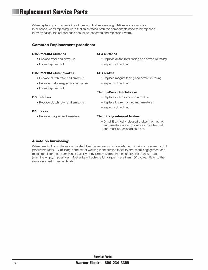
Replacement Service Parts
Service Parts
168 Warner Electric 800-234-3369
When replacing components in clutches and brakes several guidelines are appropriate.In all cases, when replacing worn friction surfaces both the components need to be replaced.In many cases, the splined hubs should be inspected and replaced if worn.
A note on burnishing:
When new friction surfaces are installed it will be necessary to burnish the unit prior to returning to fullproduction rates. Burnishing is the act of wearing in the friction faces to ensure full engagement andtherefore full torque. Burnishing is achieved by simply cycling the unit under less than full load(machine empty, if possible). Most units will achieve full torque in less than 100 cycles. Refer to theservice manual for more details.
Common Replacement practices:
EM/UM/EUM clutches
• Replace rotor and armature
• Inspect splined hub
EM/UM/EUM clutch/brakes
• Replace clutch rotor and armature
• Replace brake magnet and armature
• Inspect splined hub
EC clutches
• Replace clutch rotor and armature
EB brakes
• Replace magnet and armature
ATC clutches
• Replace clutch rotor facing and armature facing
• Inspect splined hub
ATB brakes
• Replace magnet facing and armature facing
• Inspect splined hub
Electro-Pack clutch/brake
• Replace clutch rotor and armature
• Replace brake magnet and armature
• Inspect splined hub
Electrically released brakes
• On all Electrically released brakes the magnetand armature are only sold as a matched setand must be replaced as a set.

EM Series Electro Module
Warner Electric 800-234-3369 169
Service Parts
10 Motor Clutch Module
Component Parts
EM-50 EM-100 EM-180 EM-210Item Description Part No. Qty. Part No. Qty. Part No. Qty. Part No. Qty.1* Rotor Assembly w/fan & hub 5370-751-010 1 5370-751-013 1 5370-751-007 1 5371-751-005 1
Field 1 1 1 16 volt 5370-451-011 5370-451-021 5370-451-021 5371-451-010224 volt 5370-451-014 5370-451-024 5370-451-024 5371-451-01390 volt 5370-451-012 5370-451-022 5370-451-022 5371-451-011
3 Setscrew 797-0471 4
4 Adapter 104-0096 1
Mounting Accessory 5370-101-028 1 5370-101-013 1 5370-101-013 1 5371-101-008 15-1 Capscrew 797-0293 4 797-0293 4 797-0293 4 797-1078 4
5 5-2 Lockwasher 950-0128 4 950-0128 4 950-0128 4 950-0101 45-3 Capscrew 797-1075 45-4 Lockwasher 950-0032 4
*Shipped AssembledRefer to Service Manual P-213.These units meet the standards of UL 508 and are listed under guide card #NMTR2, file #59164. These units are CSA certified under file #LR11543.
1
1
EM-50Only
5
5-35-4
5-15-2
4
3
2
Note: As of June, 2000 all rotors are manufactured as a singlepiece design. The rotor assembly part number remains thesame and now includes the hub and set screws.

Service Parts
Electro Module EM Series
170 Warner Electric 800-234-3369
20 Brake Module
page 65
14-41
54
32
1
6a
7
6b
8
14-3
9
14
10
11
13
15
12
14-214-2

EM Series Electro Module
Warner Electric 800-234-3369 171
Service Parts
20 Brake Module
Component Parts
EM-50 EM-100 EM-180 EM-210 EM-215Item Description Part No. Qty. Part No. Qty. Part No. Qty. Part No. Qty. Part No. Qty.1 Armature 5370-111-011 2 5370-111-013 2 5370-111-013 2 5371-111-005 2 5371-111-005 1
2 Armature Hub 540-1638 1 540-1684 1 540-1642 1 540-0741 1 540-2039 1
3 Retaining Ring 748-0445 1 748-0676 1 748-0676 1
4 Lockwasher 950-0372 6 950-0372 6
5 Capscrew 797-0081 6 797-008 6
6a Retaining Ring 748-0113 1 748-0101 1 748-0101 1 748-0112 1 748-0112 16b Retaining Ring 748-0113 1 748-2002 1
7 Ball Bearing 166-0149 1 166-0101 1 166-0101 1 166-0142 1 166-0142 1
Magnet 1 1 1 1
86 Volt 5370-631-008 5370-631-002 5370-631-002 5371-631-00224 Volt 5370-631-010 5370-631-005 5370-631-005 5371-631-00590 Volt 5370-631-007 5370-631-003 5370-631-003 5371-631-003 5371-631-003 1
9 Housing 535-0130 1 535-0132 1 535-0132 1 535-0033 1 535-0033 1
10 Setscrew 797-0471 4 797-0471 4 797-0471 4 797-0471 4 797-0471 4
11 Shaft 798-0045 1 798-0127 1 798-0086 1 798-0050 1 798-0268 1
12 Key - Output 590-0029 1 590-0029 1 590-0029 1 590-0019 1 590-0124 1
13 Ball Bearing 166-0155 1 166-0143 1 166-0143 1 166-0144 1 166-0144 1
Mounting Accessory 5370-101-017 1 5370-101-017 1 5370-101-023 1 5371-101-007 1 5371-101-007 114-1 Capscrew 797-0353 4 797-0353 4 797-0353 4 797-1081 4 797-1081 4
14 14-2 Washer 950-0354 4 950-0354 4 950-0354 4 950-0033 4 950-0033 414-3 Spacer 807-0218 114-4 Collar 266-0002 1 266-0003 1 266-0003 1
15 Key 590-0043 1 590-0084 1 590-0084 1
Key Accessory - Input 5370-101-072 1 5370-101-072 1 5370-101-072 1 5371-101-043 1 5371-101-044 1
Refer to Service Manual P-213.These units meet the standards of UL 508 and are listed under guide card #NMTR2, file #59164. These units are CSA certified under file #LR11543.

Service Parts
Electro Module EM Series
172 Warner Electric 800-234-3369
EM-50-20MB, EM-180-20MB, EM-210-20MB
67
810
1214
915
1311
5
19-3
19-1
17
19-2
16
18
19-4
3
12
3
4
Spacer used only if module interferes with motor housing.
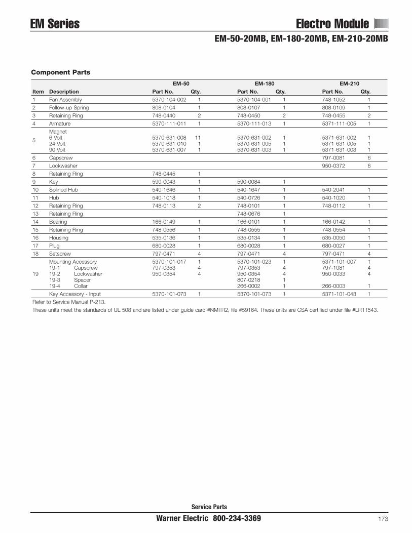
EM Series Electro Module
Warner Electric 800-234-3369 173
Service Parts
Component Parts
EM-50 EM-180 EM-210Item Description Part No. Qty. Part No. Qty. Part No. Qty.1 Fan Assembly 5370-104-002 1 5370-104-001 1 748-1052 1
2 Follow-up Spring 808-0104 1 808-0107 1 808-0109 1
3 Retaining Ring 748-0440 2 748-0450 2 748-0455 2
4 Armature 5370-111-011 1 5370-111-013 1 5371-111-005 1
Magnet6 Volt 5370-631-008 11 5370-631-002 1 5371-631-002 1524 Volt 5370-631-010 1 5370-631-005 1 5371-631-005 190 Volt 5370-631-007 1 5370-631-003 1 5371-631-003 1
6 Capscrew 797-0081 6
7 Lockwasher 950-0372 6
8 Retaining Ring 748-0445 1
9 Key 590-0043 1 590-0084 1
10 Splined Hub 540-1646 1 540-1647 1 540-2041 1
11 Hub 540-1018 1 540-0726 1 540-1020 1
12 Retaining Ring 748-0113 2 748-0101 1 748-0112 1
13 Retaining Ring 748-0676 1
14 Bearing 166-0149 1 166-0101 1 166-0142 1
15 Retaining Ring 748-0556 1 748-0555 1 748-0554 1
16 Housing 535-0136 1 535-0134 1 535-0050 1
17 Plug 680-0028 1 680-0028 1 680-0027 1
18 Setscrew 797-0471 4 797-0471 4 797-0471 4
Mounting Accessory 5370-101-017 1 5370-101-023 1 5371-101-007 119-1 Capscrew 797-0353 4 797-0353 4 797-1081 4
19 19-2 Lockwasher 950-0354 4 950-0354 4 950-0033 419-3 Spacer 807-0218 119-4 Collar 266-0002 1 266-0003 1
Key Accessory - Input 5370-101-073 1 5370-101-073 1 5371-101-043 1
Refer to Service Manual P-213.
These units meet the standards of UL 508 and are listed under guide card #NMTR2, file #59164. These units are CSA certified under file #LR11543.
EM-50-20MB, EM-180-20MB, EM-210-20MB

Service Parts
Electro Module EM Series
174 Warner Electric 800-234-3369
30 Input Clutch Module
Component Parts
EM-50 EM-100 EM-180 EM-210Item Description Part No. Qty. Part No. Qty. Part No. Qty. Part No. Qty.1 Rotor Assembly w/fan 5370-751-006 1 5370-751-009 1 5370-751-009 1 5371-751-007 1
2 Capscrew 797-1039 4 797-1214 5 797-1214 5 797-0083 6
3 Lockwasher 950-0436 4 950-0436 5 950-0436 5 950-0372 6
4 Spacer 807-0062 1 807-0062 1 807-0061 1
Field (with housing EM-50-30 only) 1 1 1 1
56 volt 5370-451-072 5370-451-007 5370-451-007 5371-451-00224 volt 5370-451-074 5370-451-005 5370-451-005 5371-451-00590 volt 5370-451-073 5370-451-008 5370-451-008 5371-451-003
6a Retaining Ring 748-0113 1 748-0101 1 748-0101 1 748-0112 16b Retaining Ring 748-0113 1
7 Ball Bearing 166-0149 1 166-0101 1 166-0101 1 166-0142 1
8 Retaining Ring 748-0017 1
9 Housing 535-0164 1 535-0164 1 535-0129 1
10 Setscrew 797-0471 4 797-0471 4 797-0471 4 797-0471 4
11 Shaft 798-0047 1 798-0129 1 798-0124 1 798-0123 1
12 Ball Bearing 166-0155 1 166-0143 1 166-0143 1 166-0144 1
Mounting Accessory 5371-101-010 113 13-1 Capscrew 797-1075 4
13-2 Lockwasher 950-0032 4
14 Key 590-0029 1 590-0029 1 590-0029 1 590-0019 1
Refer to Service Manual P-213.These units meet the standards of UL 508 and are listed under guide card #NMTR2, file #59164. These units are CSA certified under file #LR11543.
14
5
6a7
6b
8
9 13-213-1
13
12
1411
10
32
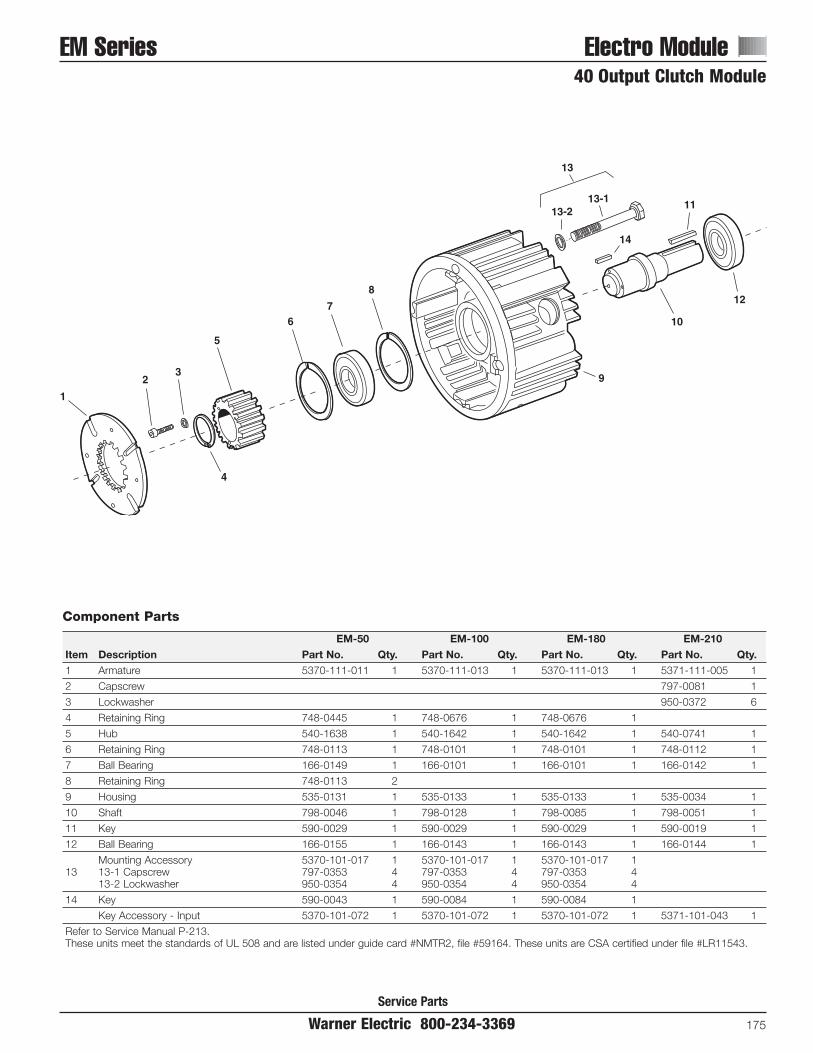
EM Series Electro Module
Warner Electric 800-234-3369 175
Service Parts
40 Output Clutch Module
Component Parts
EM-50 EM-100 EM-180 EM-210Item Description Part No. Qty. Part No. Qty. Part No. Qty. Part No. Qty.1 Armature 5370-111-011 1 5370-111-013 1 5370-111-013 1 5371-111-005 1
2 Capscrew 797-0081 1
3 Lockwasher 950-0372 6
4 Retaining Ring 748-0445 1 748-0676 1 748-0676 1
5 Hub 540-1638 1 540-1642 1 540-1642 1 540-0741 1
6 Retaining Ring 748-0113 1 748-0101 1 748-0101 1 748-0112 1
7 Ball Bearing 166-0149 1 166-0101 1 166-0101 1 166-0142 1
8 Retaining Ring 748-0113 2
9 Housing 535-0131 1 535-0133 1 535-0133 1 535-0034 1
10 Shaft 798-0046 1 798-0128 1 798-0085 1 798-0051 1
11 Key 590-0029 1 590-0029 1 590-0029 1 590-0019 1
12 Ball Bearing 166-0155 1 166-0143 1 166-0143 1 166-0144 1
Mounting Accessory 5370-101-017 1 5370-101-017 1 5370-101-017 113 13-1 Capscrew 797-0353 4 797-0353 4 797-0353 4
13-2 Lockwasher 950-0354 4 950-0354 4 950-0354 4
14 Key 590-0043 1 590-0084 1 590-0084 1
Key Accessory - Input 5370-101-072 1 5370-101-072 1 5370-101-072 1 5371-101-043 1
Refer to Service Manual P-213.These units meet the standards of UL 508 and are listed under guide card #NMTR2, file #59164. These units are CSA certified under file #LR11543.
1
23
5
4
13
13-213-1
14
10
12
11
9
8
76

Service Parts
UniModule UM Series
176 Warner Electric 800-234-3369
UM-1020 Clutch/Brake CombinationUM-1020 Combo Exploded10/21/99page 14
24
23
16
13
9
6a7
6b
8
1
3
14-3
1
10
14-2
14-1
12
11
15
10
45
2
17
20
1918
14-514-4

Service Parts
UM Series UniModule
Warner Electric 800-234-3369 177
UM-1020 Clutch/Brake Combination
Component Parts
UM-50 UM-100 UM-180 UM-210 UM-215Item Description Part No. Qty. Part No. Qty. Part No. Qty. Part No. Qty. Part No. Qty.1 Armature Assembly 5370-111-011 2 5370-111-013 2 5370-111-013 2 5371-111-005 2 5371-111-005 22 Armature Hub 540-1638 1 540-1642 1 540-1642 1 540-0741 1 540-0741 1
3 Retaining Ring 748-0445 1 748-0676 1 748-0676 1
4 Lockwasher 950-0372 6 950-0372 6
5 Capscrew 797-0081 6 797-0081 6
6a Retaining Ring 748-0113 1 748-0101 1 748-0101 1 748-0112 1 748-0112 1
6b Retaining Ring 748-0113 1
7 Ball Bearing 166-0149 1 166-0101 1 166-0101 1 166-0142 1 166-0142 1
Magnet 1 1 1 1 1
86 volt 5370-631-008 5370-631-002 5370-631-002 5371-631-002 5371-631-00224 volt 5370-631-010 5370-631-005 5370-631-005 5371-631-005 5371-631-00590 volt 5370-631-007 5370-631-003 5370-631-003 5371-631-003 5371-631-003
9 Housing 535-0165 1 535-0162 1 535-0162 1 535-0163 1 535-0163 1
10 Setscrew 797-0471 4 797-0471 4 797-0471 4 797-0471 4 797-0471 4
11 Shaft 798-0046 1 798-0128 1 798-0085 1 798-0051 1 798-0254 1
12 Key 590-0029 1 590-0029 1 590-0029 1 590-0019 1 590-0124 1
13 Ball Bearing 166-0155 1 166-0143 1 166-0143 1 166-0144 1 166-0144 1
Mounting Accessory 5370-101-040 1 5370-101-040 1 5370-101-040 1 5371-101-020 1 5371-101-020 114-1 Capscrew 797-1378 4 797-1378 4 797-1378 4 797-1440 4 797-1440 4
1414-2 Washer 950-0354 4 950-0354 4 950-0354 4 950-0111 4 950-0111 414-3 Adapter 807-0218 1 104-0321 1 104-0321 114-4 Capscrew 797-1442 4 797-1442 414-5 Washer 950-0101 4 950-0101 4
15 Key 590-0043 1 590-0084 1 590-0084 1
16Rotor Assembly 5370-751-019 1 5370-751-022 1 5370-751-017 1 5371-751-012 1 5371-751-031 1(with fan and hub)
Field (with housing) 1 1 1 1 1
176 volt 5370-451-062 5370-451-057 5370-451-057 5371-451-027 5371-451-02724 volt 5370-451-064 5370-451-059 5370-451-059 5371-451-029 5371-451-02990 volt 5370-451-063 5370-451-058 5370-451-058 5371-451-028 5371-451-028
18 Retaining Ring 748-0101 1 748-0101 1 748-0101 1 748-0558 1 748-0558 1
19 Bearing 166-0150 1 166-0101 1 166-0101 1 166-0168 1 166-0168 1
20 Retaining Ring 748-0018 1 748-0001 1 748-0001 1 748-0067 1 748-0067 1
23 Conduit Box (Optional) 5370-101-042 1 5370-101-042 1 5370-101-042 1 5370-101-042 1 5370-101-042 1
24 Set Screw 797-1098 2 797-0069 2 797-0069 2 797-1098 2 797-1098 2
Key 5370-101-072 1 5370-101-072 1 5370-101-072 1 5371-101-043 1 5371-101-044 1
Refer to Service Manual P-213.These units meet the standards of UL 508 and are listed under guide card #NMTR 2, file #59164. These units are CSA certified under file #LR11543.
Note: As of June, 2000 all rotors are manufactured as a single piece design. The rotor assembly part number remains the same and now includesthe hub and set screws.

UniModule UM Series
Service Parts
178 Warner Electric 800-234-3369
UM-1040 Clutch CombinationUM-1040 Combo Exploded11/1/99page 18
21-3
1918
21-121-2
17
14
13
1-1
1
23
53
41
20
15
12
118
2
21-421-5
109
22
16

UM Series UniModule
Service Parts
Warner Electric 800-234-3369 179
UM-1040 Clutch Combination
Component Parts
UM-50 UM-100 UM-180 UM-210 UM-215Item Description Part No. Qty. Part No. Qty. Part No. Qty. Part No. Qty. Part No. Qty.
1Rotor Assembly 5370-751-019 1 5370-751-022 1 5370-751-017 1 5371-751-012 1 5371-751-031 1(with fan and hub)
Field (with housing) 1 1 1 1 1
26 volt 5370-451-062 5370-451-057 5370-451-057 5371-451-027 5371-451-02724 volt 5370-451-064 5370-451-059 5370-451-059 5371-451-029 5371-451-02990 volt 5370-451-063 5370-451-058 5370-451-058 5371-451-028 5371-451-028
3 Retaining Ring 748-0101 1 748-0101 1 748-0101 1 748-0558 1 748-0558 1
4 Bearing 166-0150 1 166-0101 1 166-0101 1 166-0168 1 166-0168 1
5 Retaining Ring 748-0018 1 748-0001 1 748-0001 1 748-0067 1 748-0067 1
8 Armature Assembly 5370-111-011 1 5370-111-013 1 5370-111-013 1 5371-111-005 1 5371-111-005 1
9 Capscrew 797-0081 6 797-0081 6
10 Lockwasher 950-0372 6 950-0372 6
11 Retaining Ring 748-0445 1 748-0676 1 748-0676 1
12 Hub 540-1638 1 540-1642 1 540-1642 1 540-0741 1 540-0741 1
13 Retaining Ring 748-0113 1 748-0101 1 748-0101 1 748-0112 1 748-0112 1
14 Ball Bearing 166-0149 1 166-0101 1 166-0101 1 166-0142 1 166-0142 1
15 Retaining Ring 748-0113 1
16 Housing 535-0167 1 535-0168 1 535-0168 1 535-0169 1 535-0169 1
17 Shaft 798-0046 1 798-0128 1 798-0085 1 798-0051 1 798-0254 1
18 Key 590-0029 1 590-0029 1 590-0029 1 590-0019 1 590-0124 1
19 Ball Bearing 166-0155 1 166-0143 1 166-0143 1 166-0144 1 166-0144 1
20 Key 590-0043 1 590-0084 1 590-0084 1
Mounting Accessory 5370-101-040 1 5370-101-040 1 5370-101-040 1 5371-101-020 1 5371-101-020 121-1 Capscrew 797-1378 4 797-1378 4 797-1378 4 797-1440 4 797-1440 4
2121-2 Lockwasher 950-0354 4 950-0354 4 950-0354 4 950-0111 4 950-0111 421-3 Adapter 807-0218 1 104-0321 1 104-0321 121-4 Capscrew 797-1442 4 797-1442 421-5 Lockwasher 950-0101 4 950-0101 4
22Conduit Box 5370-101-042 1 5370-101-042 1 5370-101-042 1 5370-101-042 1 5370-101-042 1(Optional)
23 Set Screw 797-1098 2 797-0069 2 797-0069 2 797-1098 2 797-1098 2
Key 5370-101-072 1 5370-101-072 1 5370-101-072 1 5371-101-043 1 5371-101-044 1
Refer to Service Manual P-213.These units meet the standards of UL 508 and are listed under guide card #NMTR 2, file #59164. These units are CSA certified under file #LR11543.
Note: As of June, 2000 all rotors are manufactured as a single piece design. The rotor assembly part number remains the same and now includesthe hub and set screws.

UniModule UM Series
Service Parts
180 Warner Electric 800-234-3369
UM-2030 Clutch/Brake CombinationUM-2030 Combo Exploded11/1/99Page 22
15
19
23
2022
21
24
31
29
3028
231
5
64
78
9
11
10
1413
12
25
27
26
32
18
1617

UM Series UniModule
Service Parts
Warner Electric 800-234-3369 181
UM-2030 Clutch/Brake Combination
Component Parts
UM-50 UM-100 UM-180 UM-210 UM-215Item Description Part No. Qty. Part No. Qty. Part No. Qty. Part No. Qty. Part No. Qty.1 Rotor Assembly w/fan 5370-751-006 1 5370-751-009 1 5370-751-009 1 5371-751-007 1 5371-751-007 1
2 Capscrew 797-1294 4 797-1214 5 797-1214 5 797-0083 6 797-0083 6
3 Lockwasher 950-0436 4 950-0436 5 950-0436 5 950-0372 6 950-0372 6
4 Spacer 807-0062 1 807-0062 1 807-0061 1 807-0061 1
Field (with housing UM-50-2030 only) 1 1 1 1 1
56 volt 5370-451-072 5370-451-007 5370-451-007 5371-451-002 5371-451-00224 volt 5370-451-074 5370-451-005 5370-451-005 5371-451-005 5371-451-00590 volt 5370-451-073 5370-451-008 5370-451-008 5371-451-003 5371-451-003
6 Retaining Ring 748-0113 1 748-0101 1 748-0101 1 748-0112 1 748-0112 1
7 Ball Bearing 166-0149 1 166-0101 1 166-0101 1 166-0142 1 166-0142 1
8 Retaining Ring 748-0113 1
9 Retaining Ring 748-0017 1
10 Housing 535-0164 1 535-0164 1 535-0129 1 535-0129 1
11 Setscrew 797-0471 4 797-0471 4 797-0471 4 797-0471 4
12 Shaft 798-0047 1 798-0129 1 798-0124 1 798-0123 1 798-0255 1
13 Bearing 166-0155 1 166-0143 1 166-0143 1 166-0144 1 166-0144 1
14 Key 590-0029 1 590-0029 1 590-0029 1 590-0019 1 590-0124 1
15 Armature Assembly 5370-111-011 2 5370-111-013 2 5370-111-013 2 5371-111-005 2 5371-111-005 2
16 Armature Hub 540-1638 1 540-1642 1 540-1642 1 540-0741 1 540-0741 1
17 Retaining Ring 748-0445 1 748-0676 1 748-0676 1
18 Lockwasher 950-0372 6 950-0372 6
19 Capscrew 797-0081 6 797-0081 6
20 Retaining Ring 748-0113 1 748-0101 1 748-0101 1 748-0112 1 748-0112 1
21 Retaining Ring 748-0113 1
22 Ball Bearing 166-0149 1 166-0101 1 166-0101 1 166-0142 1 166-0142 1
Magnet 1 1 1 1 1
236 volt 5370-631-008 5370-631-002 5370-631-002 5371-631-002 5371-631-00224 volt 5370-631-010 5370-631-005 5370-631-005 5371-631-005 5371-631-00590 volt 5370-631-007 5370-631-003 5370-631-003 5371-631-003 5371-631-003
24 Housing 535-0165 1 535-0162 1 535-0162 1 535-0163 1 535-0163 1
25 Setscrew 797-0471 4 797-0471 4 797-0471 4 797-0471 4 797-0471 4
26 Shaft 798-0046 1 798-0128 1 798-0085 1 798-0051 1 798-0251 1
27 Key 590-0029 1 590-0029 1 590-0029 1 590-0019 1 590-0124 1
28 Ball Bearing 166-0155 1 166-0143 1 166-0143 1 166-0144 1 166-0144 1
29 Key 590-0043 1 590-0084 1 590-0084 1
30 Capscrew 797-0353 4 797-0353 4 797-0353 4 797-1075 4 797-1075 4
31 Lockwasher 950-0354 4 950-0354 4 950-0354 4 950-0032 4 950-0032 4
32 Conduit Box (Optional) 5370-101-042 1 5370-101-042 1 5370-101-042 1 5370-101-042 1 5370-101-042 1
Refer to Service Manual P-213.These units meet the standards of UL 508 and are listed under guide card #NMTR2, file #59164. These units are CSA certified under file #LR11543.

UniModule UM Series
Service Parts
182 Warner Electric 800-234-3369
UM-3040 Clutch Combination–Base Mounted
46
5
1 3 2
2829
22
26
27
23
25
24
2120
16
17
19
15
18
30
13
14
12
11
98
710
UM-3040 Combo Exploded11/1/99Page 26

UM Series UniModule
Service Parts
Warner Electric 800-234-3369 183
UM-3040 Clutch Combination–Base Mounted
Component Parts
UM-50 UM-100 UM-180 UM-210 UM-215Item Description Part No. Qty. Part No. Qty. Part No. Qty. Part No. Qty. Part No. Qty.1 Rotor Assembly w/fan 5370-751-006 1 5370-751-009 1 5370-751-009 1 5371-751-007 1 5371-751-007 1
2 Capscrew 797-1294 4 797-1214 5 797-1214 5 797-0083 6 797-0083 6
3 Lockwasher 950-0436 4 950-0436 5 950-0436 5 950-0372 6 950-0372 6
4 Spacer 807-0062 1 807-0062 1 807-0061 1 807-0061 1
Field (with housing UM-50-3040 only) 1 1 1 1 1
56 volt 5370-451-072 5370-451-007 5370-451-007 5371-451-002 5371-451-00224 volt 5370-451-074 5370-451-005 5370-451-005 5371-451-005 5371-451-00590 volt 5370-451-073 5370-451-008 5370-451-008 5371-451-003 5371-451-003
6 Retaining Ring 748-0113 1 748-0101 1 748-0101 1 748-0112 1 748-0112 1
7 Ball Bearing 166-0149 1 166-0101 1 166-0101 1 166-0142 1 166-0142 1
8 Retaining Ring 748-0113 1
9 Retaining Ring 748-0017 1
10 Housing 535-0164 1 535-0164 4 535-0129 1 535-0129 1
11 Setscrew 797-0471 4 797-0471 4 797-0471 4 797-0471 4
12 Shaft 798-0047 1 798-0129 1 798-0124 1 798-0123 1 798-0255 1
13 Bearing 166-0155 1 166-0143 1 166-0143 1 166-0144 1 166-0144 1
14 Key 590-0029 1 590-0029 1 590-0029 1 590-0019 1 590-0124 1
15 Armature Assembly 5370-111-011 1 5370-111-013 1 5370-111-013 1 5371-111-005 1 5371-111-005 1
16 Capscrew 797-0081 6 797-0081 6
17 Lockwasher 950-0372 6 950-0372 6
18 Retaining Ring 748-0445 1 748-0676 1 748-0676 1
19 Hub 540-1638 1 540-1642 1 540-1642 1 540-0741 1 540-0741 1
20 Retaining Ring 748-0113 1 748-0101 1 748-0101 1 748-0112 1 748-0112 1
21 Ball Bearing 166-0149 1 166-0101 1 166-0101 1 166-0142 1 166-0142 1
22 Retaining Ring 748-0113 1
23 Housing 535-0167 1 535-0168 1 535-0168 1 535-0169 1 535-0169 1
24 Shaft 798-0046 1 798-0128 1 798-0085 1 798-0051 1 798-0251 1
25 Key 590-0029 1 590-0029 1 590-0029 1 590-0019 1 590-0124 1
26 Ball Bearing 166-0155 1 166-0143 1 166-0143 1 166-0144 1 166-0144 1
27 Key 590-0043 1 590-0084 1 590-0084 1
28 Capscrew 797-0353 4 797-0353 4 797-0353 4 797-1075 4 797-1075 4
29 Lockwasher 950-0354 4 950-0354 4 950-0354 4 950-0032 4 950-0032 4
30 Conduit Box (Optional) 5370-101-042 1 5370-101-042 1 5370-101-042 1 5370-101-042 1 5370-101-042 1
Refer to Service Manual P-213.These units meet the standards of UL 508 and are listed under guide card #NMTR2, file #59164. These units are CSA certified under file #LR11543.

Enclosed UniModule EUM/EUM-W Series
184 Warner Electric 800-234-3369Service Parts
EUM-1020 Clutch/Brake CombinationEUM-W-1020 Clutch/Brake Combination
EUM-1020 Exploded
10 1817
17a 11a
Optional
1515W
11
19
Optional
2121W
4
23
5
14
2020W22
13
21
7a6
13
13a
9
8
9a
2a
1616W
16a7b
26W
26W
14W
EUM-W Modification
Spare Parts
1212W

Service Parts
EUM/EUM-W Series Enclosed UniModule
Warner Electric 800-234-3369 185
EUM-1020 Clutch/Brake CombinationEUM-W-1020 Clutch/Brake Combination
Component Parts
EUM-50 EUM-100 EUM-180 EUM-210 EUM-215Item Description Part No. Qty. Part No. Qty. Part No. Qty. Part No. Qty. Part No. Qty.1 Armature Assembly 5370-111-011 2 5370-111-013 2 5370-111-013 2 5371-111-005 2 5371-111-005 2
2 Armature Hub 540-1638 1 540-1642 1 540-1642 1 540-0741 1 540-0741 1
2a Key 590-0043 1 590-0084 1 590-0084 1
3 Retaining Ring 748-0445 1 748-0676 1 748-0676 1
4 Lockwasher 950-0121 6 950-0121 6
5 Capscrew 797-0081 6 797-0081 6
6 Retaining Ring 748-0113 2 748-0101 1 748-0101 1 748-0112 1 748-0112 1
7a Ball Bearing 166-0149 1 166-0101 1 166-0101 1 166-0142 1 166-0142 1
7b Ball Bearing 166-0155 1 166-0143 1 166-0143 1 166-0144 1 166-0144 1
8 Endbell/Brake 456-1014 1 456-1019 1 456-1019 1 456-1017 1 456-1017 1
Brake Magnet
96 volt 5370-631-037 5370-631-002 5370-631-002 5371-631-002 5371-631-00224 volt 5370-631-038 5370-631-005 5370-631-005 5371-631-005 5371-631-00590 volt 5370-631-036 5370-631-003 5370-631-003 5371-631-003 5371-631-003
9a Set Screws 797-0471 4 797-0471 4 797-0471 4 797-0471 4 797-0471 4
Clutch Field/Endbell Assembly6 volt 5370-451-077 1 5370-451-086 1 5370-451-086 1 5371-451-033 1 5371-451-033 11024 volt 5370-451-078 1 5370-451-087 1 5370-451-087 1 5371-451-034 1 5371-451-034 190 volt 5370-451-076 1 5370-451-085 1 5370-451-085 1 5371-451-032 1 5371-451-032 1
11 Rotor/Hub Assembly 5370-751-023 1 5370-751-035 1 5370-751-024 1 5371-751-014 1 5371-751-033 1
11a Set Screws 797-1098 2 797-0069 2 797-0069 2 797-1098 2 797-1098 2
12 Mounting Accessory Kit 5370-101-040 1 5370-101-040 1 5370-101-040 1 5371-101-024 1 5371-101-024 1
13 Cover Plate 686-1055 1 686-1055 1 686-1055 1 686-1055 1 686-1055 1
13a Cover Plate Screws 797-0575 4 797-0575 4 797-0575 4 797-0575 4 797-0575 4
14 Center Housing 535-0176 1 535-0176 1 535-0176 1 535-0177 1 535-0177 1
15 Conduit Box (optional) 5370-101-042 1 5370-101-042 1 5370-101-042 1 5370-101-042 1 5370-101-042 1
16 Shaft 798-0046 1 798-0128 1 798-0085 1 798-0051 1 798-0254 1
16a Key 590-0029 1 590-0029 1 590-0029 1 590-0019 1 590-0124 1
17 Retaining Ring 748-0101 2 748-0101 1 748-0101 1 748-0558 1 748-0558 1
17a Ball Bearing 166-0150 1 166-0300 1 166-0300 1 166-0168 1 166-0168 1
18 Retaining Ring 748-0018 1 748-0018 1 748-0018 1 748-0067 1 748-0067 1
19 Assembly Bolts 797-1433 2 797-1433 2 797-1433 2 797-1438 2 797-1438 2
20 Connector 280-0038 1 280-0038 1 280-0038 1 280-0038 1 280-0038 1
21 Accessory Fan (optional) 5370-101-055 1 5370-101-055 1 5370-101-054 1 5371-101-029 1 N/A
22 Washer 950-0441 1 950-0441 1 950-0441 1 950-0441 1 950-0441 1
23 Insulator 572-0327 1 572-0327 1 572-0327 1 572-0327 1 572-0327 1
EUM-W Unique Parts12W Washdown Mounting Kit 5370-101-052 1 5370-101-052 1 5370-101-052 1 5371-101-028 1 5371-101-028 1
14W Center Housing for Washdown 535-0181 1 535-0181 1 535-0181 1 535-0182 1 535-0182 1
15W Conduit Box Kit 5370-101-045 1 5370-101-045 1 5370-101-045 1 5370-101-045 1 5370-101-045 1
16W Shaft 798-0263 1 798-0265 1 798-0262 1 798-0259 1 798-0267 1
20W Conduit Connector 280-0058 1 280-0058 1 280-0058 1 280-0058 1 280-0058 1
21W Fan Kit (optional) 5370-101-060 1 5370-101-060 1 5370-101-061 1 5371-101-033 1 N/A
26W Gasket/Seal Repair Kit 5370-101-058 1 5370-101-058 1 5370-101-058 1 5371-101-032 1 5371-101-032 1
Key 5370-101-072 1 5370-101-072 1 5370-101-072 1 5371-101-043 1 5371-101-044 1
Refer to Service Manual P-213.These units meet the standards of UL 508 and are listed under guide card #NMTR 2, file #59164. These units are CSA certified under file #LR11543.
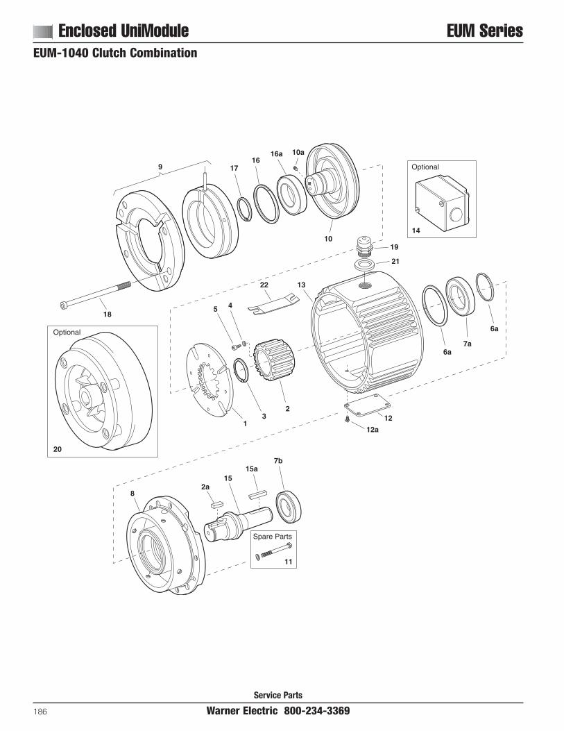
Service Parts
Enclosed UniModule EUM Series
186 Warner Electric 800-234-3369
EUM-1040 Clutch CombinationEUM-1040 Combo Exploded11/2/99page 52
Optional
14
9 1716
16a
10
10a
18
19
21
6a7a
6aOptional
20
5 4
22 13
13
212
12a
82a
1515a
7b
Spare Parts
11
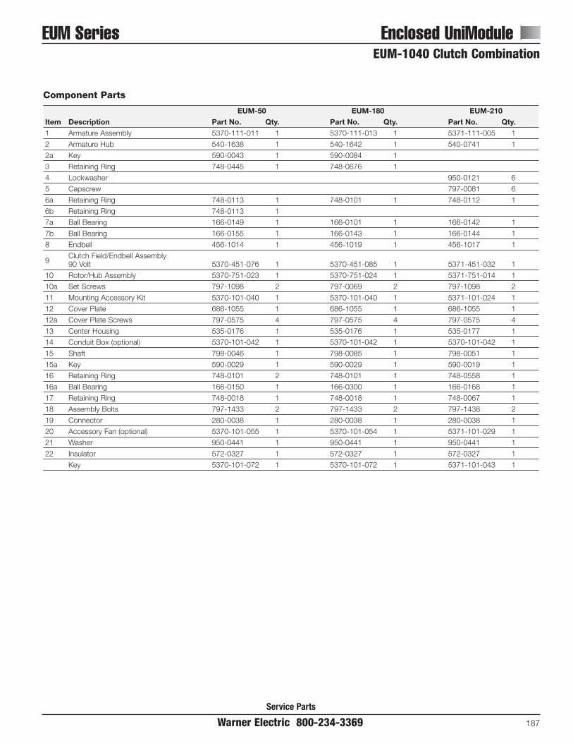
Service Parts
EUM Series Enclosed UniModule
Warner Electric 800-234-3369 187
EUM-1040 Clutch Combination
Component Parts
EUM-50 EUM-180 EUM-210Item Description Part No. Qty. Part No. Qty. Part No. Qty.1 Armature Assembly 5370-111-011 1 5370-111-013 1 5371-111-005 1
2 Armature Hub 540-1638 1 540-1642 1 540-0741 1
2a Key 590-0043 1 590-0084 1
3 Retaining Ring 748-0445 1 748-0676 1
4 Lockwasher 950-0121 6
5 Capscrew 797-0081 6
6a Retaining Ring 748-0113 1 748-0101 1 748-0112 1
6b Retaining Ring 748-0113 1
7a Ball Bearing 166-0149 1 166-0101 1 166-0142 1
7b Ball Bearing 166-0155 1 166-0143 1 166-0144 1
8 Endbell 456-1014 1 456-1019 1 456-1017 1
9Clutch Field/Endbell Assembly90 Volt 5370-451-076 1 5370-451-085 1 5371-451-032 1
10 Rotor/Hub Assembly 5370-751-023 1 5370-751-024 1 5371-751-014 1
10a Set Screws 797-1098 2 797-0069 2 797-1098 2
11 Mounting Accessory Kit 5370-101-040 1 5370-101-040 1 5371-101-024 1
12 Cover Plate 686-1055 1 686-1055 1 686-1055 1
12a Cover Plate Screws 797-0575 4 797-0575 4 797-0575 4
13 Center Housing 535-0176 1 535-0176 1 535-0177 1
14 Conduit Box (optional) 5370-101-042 1 5370-101-042 1 5370-101-042 1
15 Shaft 798-0046 1 798-0085 1 798-0051 1
15a Key 590-0029 1 590-0029 1 590-0019 1
16 Retaining Ring 748-0101 2 748-0101 1 748-0558 1
16a Ball Bearing 166-0150 1 166-0300 1 166-0168 1
17 Retaining Ring 748-0018 1 748-0018 1 748-0067 1
18 Assembly Bolts 797-1433 2 797-1433 2 797-1438 2
19 Connector 280-0038 1 280-0038 1 280-0038 1
20 Accessory Fan (optional) 5370-101-055 1 5370-101-054 1 5371-101-029 1
21 Washer 950-0441 1 950-0441 1 950-0441 1
22 Insulator 572-0327 1 572-0327 1 572-0327 1
Key 5370-101-072 1 5370-101-072 1 5371-101-043 1

Service Parts
Enclosed UniModule EUM/EUM-W Series
188 Warner Electric 800-234-3369
EUM-2030 Exploded11/8/99page 56
22
16a
1212W
10 18
2117
2311a11b
1515W
Optional
19
9a
11
8
9
9a
6b
76a
25
2020W
14
26
5 4
13
21
1313a
1616W
2a
16a24 Spare
Parts
(6)
(8)
(2)
27W
EUM-W Modification
28W
28W
14W
10a
EUM-2030 Clutch/Brake CombinationEUM-W-2030 Clutch/Brake Combination

Service Parts
EUM/EUM-W Series Enclosed UniModule
Warner Electric 800-234-3369 189
EUM-2030 Clutch/Brake CombinationEUM-W-2030 Clutch/Brake Combination
Component Parts
EUM-50 EUM-180 EUM-210Item Description Part No. Qty. Part No. Qty. Part No. Qty.1 Armature Assembly 5370-111-011 2 5370-111-013 2 5371-111-005 2
2 Armature Hub 540-1638 1 540-1642 1 540-0741 1
2a Key 590-0043 1 590-0084 1
3 Retaining Ring 748-0445 1 748-0676 1
4 Lockwasher 950-0121 6
5 Capscrew 797-0081 6
6a Retaining Ring 748-0113 2 748-0101 1 748-0112 1
6b Retaining Ring 748-2002 1
7 Ball Bearing 166-0149 1 166-0101 1 166-0142 1
8 Endbell/Brake 456-1014 1 456-1019 1 456-1017 1
Brake Magnet
96 volt 5370-631-037 1 5370-631-002 1 5371-631-002 124 volt 5370-631-038 1 5370-631-005 1 5371-631-005 190 volt 5370-631-036 1 5370-631-003 1 5371-631-003 1
9a Set Screws 797-0471 4 797-0471 4 797-0471 8
Field (with Endbell EUM-50 and EUM-180)
106 volt 5370-451-082 1 5370-451-090 1 5371-451-002 124 volt 5370-451-083 1 5370-451-091 1 5371-451-005 190 volt 5370-451-081 1 5370-451-089 1 5371-451-003 1
10a Endbell (EUM-210 only) 456-1018 1
11 Rotor 5370-751-033 1 5370-751-034 1 5371-751-006 1
11a Screw 797-1294 4 797-1214 5 797-0081 6
11b Washer 950-0102 4 950-0102 5 950-0121 6
12 Shaft/Clutch 798-0047 1 798-0124 1 798-0123 1
13 Cover Plate 686-1055 1 686-1055 1 686-1055 1
13a Screws 797-0575 4 797-0575 4 797-0575 4
14 Center Housing 535-0176 1 535-0176 1 535-0177 1
15 Conduit Box (optional) 5370-101-042 1 5370-101-042 1 5370-101-042 1
16 Shaft/Brake 798-0046 1 798-0085 1 798-0051 1
16a Key 590-0029 2 590-0029 2 590-0019 2
17 Retaining Ring 748-0113 2 748-0101 1 748-0112 1
18 Retaining Ring 748-0017 1 748-0202 1
19 Assembly Bolts 797-1477 2 797-1477 2 797-1476 2
20 Connector 280-0038 1 280-0038 1 280-0038 1
21 Bearing 166-0149 1 166-0101 1 166-0142 1
22 Bearing 166-0155 1 166-0143 1 166-0144 1
23 Spacer 807-0062 1 807-0061 1
24 Bearing 166-0155 1 166-0143 1 166-0144 1
25 Washer 950-0441 1 950-0441 1 950-0441 1
26 Insulator 572-0327 1 572-0327 1 572-0327 1
EUM-W Unique Parts12W Shaft/Clutch 798-0264 1 798-0261 1 798-0260 1
14W Center Housing for Washdown 535-0181 1 535-0181 1 535-0182 1
15W Conduit Box Kit (optional) 5370-101-045 1 5370-101-045 1 5370-101-045 1
16W Shaft/Brake 798-0263 1 798-0262 1 798-0259 1
20W Conduit Connector 280-0058 1 280-0058 1 280-0058 1
27W Washdown Mounting Kit 5370-101-051 1 5370-101-051 1 5371-101-027 1
28W Gasket/Seal Repair Kit 5370-101-058 1 5370-101-058 1 5371-101-032 1
Refer to Service Manual P-213.These units meet the standards of UL 508 and are listed under guide card #NMTR 2, file #59164. These units are CSA certified under file #LR11543.

Service Parts
Electro Clutch EC Series
190 Warner Electric 800-234-3369
page 78
17
A
78
917
1110
11
1213
14A
18
15 16
14-1
6
543
17
1-4
1-21-1
1-3
1
1-5
2
Static Max. Inertia–WR2 (lb. ft2) TotalModel Voltage Torque Speed Armature Outer Inner WeightSize DC (lb. ft.) RPM & Carrier Rotor Sleeve Sleeve lbs.
6 16 lb. ft. 5000 .010 .018 .001 .001 4EC-375 24 16 lb. ft. 5000 .010 .018 .001 .001 4
90 16 lb. ft. 5000 .010 .018 .001 .001 4
6 30 lb. ft. 4500 .072 .033 .006 .002 8EC-475 24 30 lb. ft. 4500 .072 .033 .006 .002 8
90 30 lb. ft. 4500 .072 .033 .006 .002 8
6 95 lb. ft. 3600 .106 .202 .010 .013 18EC-650 24 95 lb. ft. 3600 .106 .202 .010 .013 18
90 95 lb. ft. 3600 .106 .202 .010 .013 18
For information on Coil Data see page 138.
Electrical and Mechanical Data
EC-375, EC-475, EC-650

Service Parts
EC Series Electro Clutch
Warner Electric 800-234-3369 191
EC-375, EC-475, EC-650
Component Parts
EC-375 EC-475 EC-650Item Description Part No. Qty. Part No. Qty. Part No. Qty.
Armature & Carrier Assembly 5380-101-006 1 5181-101-003 1 5281-101-003 11-1 Capscrew 797-1214 3 797-1214 3 797-0086 3
11-2 Lockwasher 950-0102 3 950-0102 3 950-0102 31-3 Autogap Accessory 5180-101-011 3 5181-101-010 4 5181-101-010 41-4 Carrier 5380-295-002 1 5181-295-002 1 5281-295-002 11-5 Armature 5180-111-002 1 5181-111-002 1 5281-111-002 1
Inner Sleeve 1 1 11/2" Bore 803-00545/8" Bore 803-0055 803-00443/4" Bore 803-0042
2 7/8” Bore 803-00431" Bore 803-00471-1/8" Bore 803-00491-1/4" Bore 803-00481-3/8" Bore 803-0050
3 Screw 797-1050 6 797-1039 4 797-0083 4
4 Lockwasher 950-0105 6 950-0102 4 950-0103 4
5 Retainer Plate 748-0391 1 748-0393 1 748-0389 1
6 Rotor 5180-751-001 1 5181-751-001 1 5281-751-001 1
7 Ball Bearing 166-0149 1 166-0109 1 166-0110 1
8 Retainer ring 748-0017 1 748-0023 1 748-0002 1
9 Outer Sleeve 5180-104-001 1 5181-014-001 1 5281-104-001 1
10 Sleeve Bearing 166-0177 1 166-0179 1 166-0178 1
11 Oil Seal 795-0027 2 795-0028 2 795-0026 2
12 Retainer Ring 748-0101 1 748-0102 1 748-0104 1
13 Ball Bearing 166-0150 1 166-0110 1 166-0104 1
Field 1 1 16 volt 5180-451-002 5181-451-002 5281-451-002
14 24 volt 5180-451-004 5181-451-004 5281-451-00490 volt 5180-451-005 5181-451-005 5281-451-00514-1 Terminal Accessory 5103-101-002 1 5103-101-002 1 5311-101-001 1
15 Retainer Ring 748-0018 1 748-0002 1 748-0004 1
16 Set Collar 266-0011 1 266-0012 1 266-0010 1
Accessory, W/Keys 1 1 11/2" Bore 5180-101-0015/8" Bore 5180-101-001 5181-101-0013/4" Bore 5181-101-001
17 7/8" Bore 5181-101-0021" Bore 5281-101-0011-1/8" Bore 5281-101-0011-1/4" Bore 5281-101-0011-3/8" Bore 5281-101-002
18 Conduit Box 5200-101-010 1 5200-101-010 1 5200-101-010 1
These units when used with the correct Warner Electric conduit box, meets the standards of UL508 and are listed under guide care #NMTR, file#59164. These units are CSA Certified under file #LR11543.Refer to Service Manual P-210.

Service Parts
Electro Clutch EC Series
192 Warner Electric 800-234-3369
EC-825
page 81
1
1c
1b
1a
32
13
12
13
20
17
19
14
16
18
4
56
7 9
810
11 20
15

Service Parts
EC Series Electro Clutch
Warner Electric 800-234-3369 193
EC-825
Component Parts
EC-825Item Description Part No. Qty.
Armature Assembly 5282-111-002 1
11a Hub 540-1298 11b Autogap Accessory 5201-101-068 31c Armature 5282-111-001 1
2 Capscrew 797-0081 4
3 Lockwasher 950-0103 4
Inner Sleeve 11-1/8” Bore 803-006941-1/4” Bore 803-00701-3/8” Bore 803-0071
5 Capscrew 797-0086 4
6 Lockwasher 950-0103 4
7 Rotor Assembly 5282-751-001 1
8 Ball Bearing 166-0110 1
9 Retainer Ring 748-0102 1
10 Retainer Ring 748-0002 1
11 Rotor Adapter 5282-105-002 1
EC-825Item Description Part No. Qty.12 Roller Bearing 166-0178 1
13 Oil Seal 795-0026 2
14 Retainer Ring 748-0104 1
15 Ball Bearing 166-0104 1
16 Retainer Ring 748-0004 1
Field
176 volt 5282-451-00224 volt 5282-451-00490 volt 5282-451-005
18 Set Collar 266-0010 1
19 Conduit Box 5200-101-012 1
20 Mounting Accessory with Keys 5282-101-001 1
Refer to Service Manual P-210.
These units when used with the correct Warner Electric conduit box,meets the standards of UL508 and are listed under guide care #NMTR,file #59164. These units are CSA Certified under file #LR11543.

Service Parts
Electro Clutch EC Series
194 Warner Electric 800-234-3369
EC-1000, EC-1225
EC-1000, 1225 Exploded11/5/99page 84
1
1-1 1-2
1-4
21
1112
1413
21
15
1617
18
20
1922
34
2
5
67
8
21
10
9 10
1-3
1-5

Service Parts
EC Series Electro Clutch
Warner Electric 800-234-3369 195
EC-1000, EC-1225
Component Parts
EC-1000 EC-1225Item Description Part No. Qty. Part No. Qty.
Armature & Carrier Assembly 5283-111-001 1 5284-111-001 11-1 Capscrew 797-1163 6 797-1163 8
11-2 Lockwasher 950-0111 6 950-0111 81-3 Autogap Accessory 5201-101-008 3 5201-101-008 41-4 Hub 540-1338 1 540-1340 11-5 Armature 5302-111-013 1 5385-111-003 1
Inner Sleeve 1 13/8" Bore 803-00271-1/2" Bore 803-0166
2 1-5/8" Bore 803-00281-5/8" Bore 803-00781-7/8" Bore 803-00302-1/8" Bore 803-0031
3 Capscrew 797-0083 8 797-0416 8
4 Lockwasher 950-0103 8 950-0106 8
5 Rotor Assembly 5283-101-002 1 5284-101-006 1
6 Ball Bearing 166-0168 1 166-0170 1
7 Retainer Ring 748-0067 1 748-0503 1
8 Outer Sleeve 803-0025 1 803-0032 1
9 Roller Bearing 166-0180 1 166-0181 1
10 Oil Seal 795-0029 2 795-0033 2
11 Adapter Ring 748-0480 1 748-0466 1
12 Ball Bearing 166-0163 1 166-0163 1
13 Retainer Ring 748-0502 1 748-0502 1
14 Retainer Ring 748-0114 1 748-0114 1
Field 1 1
156 volt 5283-451-002 5284-451-00224 volt 5283-451-010 5284-451-01090 volt 5283-451-003 5284-451-003
16 Lockwasher 950-0355 6 950-0359 6
17 Capscrew 797-0083 6 797-0416 6
18 Set Collar 266-0015 1 266-0016 1
19 Set Screw 797-0468 2 797-0130 2
20 Terminal Accessory 5311-101-001 1 5311-101-001 1
Mounting Accessory with Keys 1 11-3/8" Bore 5283-101-0051-1/2" Bore 5283-101-009211-5/8" Bore 5283-101-006 5284-101-0071-7/8" Bore 5284-101-0012-1/8" Bore 5284-101-002
22 Conduit Box 5200-101-011 1 5200-101-011 1
Refer to Service Manual P-210.These units when used with the correct Warner Electric conduit box, meets the standards of UL508 and are listed under guide care #NMTR, file#59164. These units are CSA Certified under file #LR11543.

Service Parts
Electro Brake EB Series
196 Warner Electric 800-234-3369
EB-375, EB-475, EB-650
EB-375, 475, 650 Exploded11/7/99page 90
1-11-2
1-4
1-3
1
911
10
4
3
1-5
2
3
56
7
14Optional
12
8
15
13
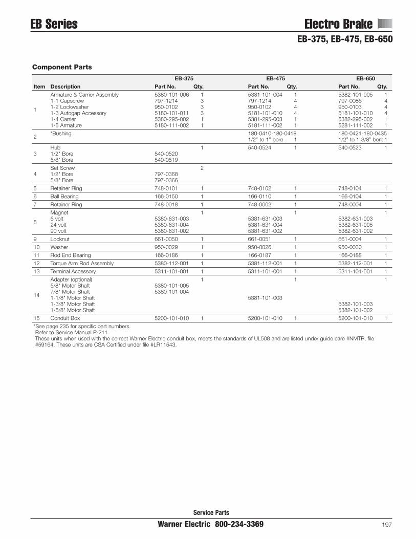
Service Parts
EB Series Electro Brake
Warner Electric 800-234-3369 197
EB-375, EB-475, EB-650
Component Parts
EB-375 EB-475 EB-650Item Description Part No. Qty. Part No. Qty. Part No. Qty.
Armature & Carrier Assembly 5380-101-006 1 5381-101-004 1 5382-101-005 11-1 Capscrew 797-1214 3 797-1214 4 797-0086 41-2 Lockwasher 950-0102 3 950-0102 4 950-0103 411-3 Autogap Accessory 5180-101-011 3 5181-101-010 4 5181-101-010 41-4 Carrier 5380-295-002 1 5381-295-003 1 5382-295-002 11-5 Armature 5180-111-002 1 5181-111-002 1 5281-111-002 1
2*Bushing 180-0410-180-0418 180-0421-180-0435
1/2” to 1” bore 1 1/2” to 1-3/8” bore 1
Hub 1 540-0524 1 540-0523 13 1/2" Bore 540-0520
5/8" Bore 540-0519
Set Screw 24 1/2" Bore 797-0368
5/8" Bore 797-0366
5 Retainer Ring 748-0101 1 748-0102 1 748-0104 1
6 Ball Bearing 166-0150 1 166-0110 1 166-0104 1
7 Retainer Ring 748-0018 1 748-0002 1 748-0004 1
Magnet 1 1 1
86 volt 5380-631-003 5381-631-003 5382-631-00324 volt 5380-631-004 5381-631-004 5382-631-00590 volt 5380-631-002 5381-631-002 5382-631-002
9 Locknut 661-0050 1 661-0051 1 661-0004 1
10 Washer 950-0029 1 950-0026 1 950-0030 1
11 Rod End Bearing 166-0186 1 166-0187 1 166-0188 1
12 Torque Arm Rod Assembly 5380-112-001 1 5381-112-001 1 5382-112-001 1
13 Terminal Accessory 5311-101-001 1 5311-101-001 1 5311-101-001 1
Adapter (optional) 1 1 15/8" Motor Shaft 5380-101-005
147/8" Motor Shaft 5380-101-0041-1/8" Motor Shaft 5381-101-0031-3/8" Motor Shaft 5382-101-0031-5/8" Motor Shaft 5382-101-002
15 Conduit Box 5200-101-010 1 5200-101-010 1 5200-101-010 1
*See page 235 for specific part numbers.Refer to Service Manual P-211.These units when used with the correct Warner Electric conduit box, meets the standards of UL508 and are listed under guide care #NMTR, file#59164. These units are CSA Certified under file #LR11543.
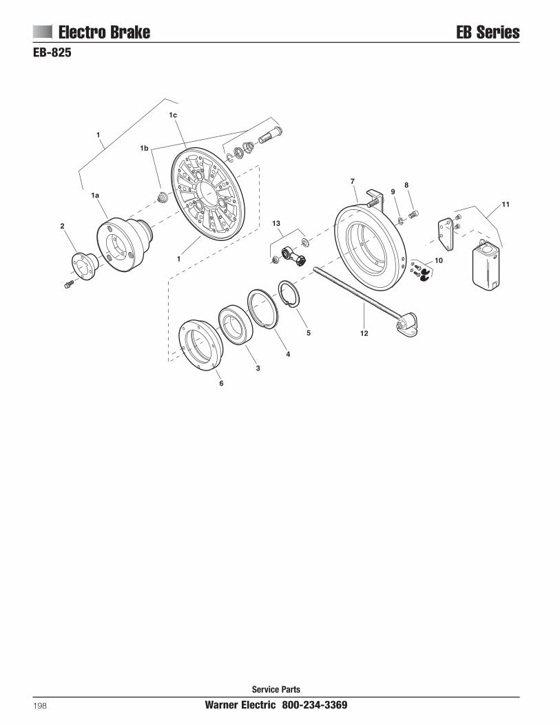
Service Parts
Electro Brake EB Series
198 Warner Electric 800-234-3369
EB-825
1
1c
1b
2
1a
1
13
6
3
4
5 12
79
8
10
11

EB Series Electro BrakeEB-825
Warner Electric 800-234-3369 199
Service Parts
Component Parts
EB-825Item Description Part No. Qty.
Armature Assembly 5383-111-001 1
11a Hub 540-1299 11b Autogap Assembly 5201-101-008 31c Armature 5282-111-001 1
2*Bushing 180-0002 to 180-0018
1/2" to 1-1/2" Bore 1
3 Ball Bearing 166-0168 1
4 Retainer Ring 748-0120 1
5 Retainer Ring 748-0584 1
6 Adapter Ring 748-0631 1
EB-825Item Description Part No. Qty.
Magnet Assembly 1
76 volt 5383-631-00224 volt 5383-631-00490 volt 5383-631-005
8 Capscrew 797-0079 6
9 Lockwasher 950-0372 6
10 Terminal Accessory 5311-101-001 1
11 Conduit Box 5200-101-011 1
12 Torque Arm Rod Assembly 5382-112-001 1
13 Rod End Assembly 5382-101-007 1
*See page 235 for specific part numbers.Refer to Service Manual P-211.These units when used with the correct Warner Electric conduit box, meets the standards of UL508 and are listed under guide care #NMTR, file #59164.

Service Parts
Electro Brake EB Series
200 Warner Electric 800-234-3369
EB-1000, EB-1225EB-100, 1225 Exploded11/10/99page 96
14
Optional
1-1 1-2
1-4
1-52
3
1-3
1
13-4 13-3
8
12-1
74
5 6
12-312-2
12
12-1
12-312-2
12-4
11
15
910
13-1
13-2
12-212-3
12-5
13

Service Parts
EB Series Electro Brake
Warner Electric 800-234-3369 201
EB-1000, EB-1225
Component Parts
EB-1000 EB-1225Item Description Part No. Qty. Part No. Qty.
Armature & Carrier Assembly 5384-111-003 1 5385-111-004 11-1 Capscrew 797-1163 6 797-1163 8
11-2 Lockwasher 950-0111 6 950-0111 81-3 Autogap Accessory 5201-101-008 3 5201-101-008 41-4 Hub 540-1339 1 540-1341 11-5 Armature 5302-111-013 1 5385-111-003 1
2*Bushing 180-0131-180-0149 180-0185-180-0217
1/2" to 1-5/8" bore 1 1/2" to 2-1/2" bore 1
3 Hub 540-0579 1 540-0578 1
4 Ball Bearing 166-0164 1 166-0163 1
5 Retainer Ring 748-0116 1 748-0114 1
6 Retiner Ring 748-0501 1 748-0074 1
7 Adapter Ring 748-0467 1 748-0465 1
Magnet Assembly 1 1
86 volt 5384-631-002 5385-631-00224 volt 5384-631-009 5385-631-00990 volt 5384-631-003 5385-631-003
9 Capscrew 797-0416 6 797-0416 6
10 Lockwasher 950-0106 6 950-0106 6
11 Terminal Accessory 5311-101-001 1 5311-101-001 1
Torque Arm Rod Assembly 5385-757-001 1 5385-757-001 112-1 Ball Joint 585-0001 2 585-0001 2
1212-2 Jam Nut 661-0012 3 661-0012 312-3 Lockwasher 950-0114 3 950-0114 312-4 Threaded Rod 756-0030 1 756-0030 112-5 Bracket 174-0073 1 174-0073 1
Torque Arm Mounting Accessory 5385-101-001 1 5385-101-001 113-1 Capscrew 797-0293 2 797-0293 2
13 13-2 Lockwasher 950-0354 2 950-0354 213-3 Jam Nut 661-0012 1 661-0012 113-4 Lockwasher 950-0114 1 950-0114 1
Adapter (optional) 1 11-5/8" Motor Shaft 5384-101-008
14 1-7/8" Motor Shaft 5384-101-0072-1/8" Motor Shaft 5384-101-010 5385-101-0082-3/8" Motor Shaft 5385-101-007
15 Conduit Box 5200-101-011 1 5200-101-011 1
*See page 235 for specific part numbers.Refer to Service Manual P-211.These units when used with the correct Warner Electric conduit box, meets the standards of UL508 and are listed under guide care #NMTR, file#59164. These units are CSA Certified under file #LR11543.

AT Clutch ATC Series
Service Parts
202 Warner Electric 800-234-3369
ATC-25, ATC-55, ATC-115
ATC-25, 55, 115 Exploded
2
3
9
12
14
15
13
11
16
7-1
6
10
8-1
8
Optional
Optional
5
4
7-37-2
7-2
7-37-4
1
8-2
8-48-3
8-5

ATC Series AT Clutch
Service Parts
Warner Electric 800-234-3369 203
ATC-25, ATC-55, ATC-115Component Parts
ATC-25 ATC-55 ATC-115Item Description Part No. Qty. Part No. Qty. Part No. Qty.1 Armature Hub 540-0907 1 540-0852 1 540-0863 12 Retaining Ring 748-0732 1 748-0726 1 748-0737 13 Retaining Ring 748-0731 1 748-0728 1 748-0736 14 Bearing 166-0278 2 166-0277 2 166-0279 25 Spacer 807-0119 1 807-1061 1 807-1063 1
Splined Hub 1 1 11/2" Bore 540-09105/8" Bore 540-09113/4" Bore 540-0912 540-1501
6 7/8" Bore 540-0913 540-15021" Bore 540-15031-1/8" Bore 540-1504 540-08571-1/4" Bore 540-08581-3/8" Bore 540-08591-1/2" Bore 540-0860
*7-1 Armature 110-0220 1 110-0218 1 110-0223 1*7-2 Screw 797-1519 4 797-1462 6 797-1463 6*7-3 Lockwasher 950-0436 4 950-0355 6 950-0355 6*7-4 Flatwasher 950-0023 2 950-0023 2*8 Rotor 5161-751-001 1 5162-751-001 1 5163-751-001 18-1 Facing Assembly 5161-445-003 1 5162-445-003 1 5163-445-003 18-2 Retainer Plate 686-0108 18-3 Detent Ring 748-2031 1 748-2038 1 748-2020 18-4 Wave Spring 808-0404 1 808-0401 1 808-0384 28-5 Machine Screw 797-1389 8 797-1389 8 797-1389 8*9 Bearing 166-0283 1 166-0284 1 166-0279 1
Field Assembly 1 1 1
106 volts DC 5161-451-002 5162-451-002 5163-451-00290 volts DC 5161-451-003 5162-451-003 5163-451-00324 volts DC 5161-451-004 5162-451-004 5163-451-004
*11 Retainer Ring 748-0018 1 748-0727 1 748-0737 112 Adapter 104-0300 213 Screw 797-1396 414 Lockwasher 950-0102 4Optional Accessory Items15 Conduit box 100-1 5162-101-002 1 5162-101-002 1 5162-101-002 116 Restraining Arm Assembly 5162-101-004 1 5162-101-004 1 5163-101-004 1Kit Items
* Clutch Rebuild Kit 5161-101-011 1 5162-101-011 1 5163-101-011 1(includes items 7-1, 7-2, 7-3, 7-4, 8, 9, 11)Note: In some versions of this product, item 8 consists of a one (1) piece rotor.Friction Face Replacement Kit 5161-101-007 5162-101-007 5163-101-007For Clutches with Replaceable Friction Face Only
Mounting Accessory Kits (not shown)1 1/2” Bore - 3/4” Bore 5161-101-0011-1 Ring Retainer Ext. 748-0734 11-2 Wire Retainer 742-0027 11-3 Key 590-0104 11-4 Setscrew 797-1393 21 7/8’ Bore 5161-101-0021-1 Ring Retainer Ext. 748-0734 11-2 Wire Retainer 742-0027 11-3 Key 590-0104 11-4 Collar and Setscrew 266-0031 11 3/4’ Bore - 1” Bore 5162-101-0011-1 Ring Retainer Ext. 748-0725 11-2 Wire Retainer 742-0026 11-3 Key 590-0103 11-4 Setscrew 797-1386 21 1-1/8’ Bore 5162-101-0101-1 Ring Retainer Ext. 748-0725 11-2 Wire Retainer 742-0026 11-3 Key 590-0103 11-4 Setscrew 797-1077 21-5 Collar 266-0032 11 All bore sizes 5163-101-0011-1 Ring Retainer Ext. 748-0738 11-2 Wire Retainer 742-0026 11-3 Key 590-0105 11-4 Setscrew 797-1395

AT Brake ATB Series
Service Parts
204 Warner Electric 800-234-3369
ATB-25, ATB-55, ATB-115
Electrical and Mechanical Data
Model Voltage Resistance Current Coil Build Up Coil Decay Inertia*–WR2 Max. WeightSize DC Unit (Ohms) (Amps) Watts (MMS) (MMS) (lb.ft.2) RPM lbs.
6 1.37 4.38 26.3 145 9 .048 3600 825 24 Brake 20.2 1.19 28.6 145 9 .048 3600 8
90 290 .31 27.9 145 9 .048 3600 8
6 1.21 4.96 29.8 210 35 .173 3600 1855 24 Brake 19.6 1.22 29.3 210 35 .173 3600 18
90 230 .39 35.2 210 35 .173 3600 18
6 1.02 5.91 35.4 150 45 .483 3600 28115 24 Brake 16.5 1.46 35 150 45 .483 3600 28
90 182 .50 44.6 150 45 .483 3600 28
page 110
17(Optional)
16(Optional)
2
1
3
4
5
7-47-5
7-47-5
7-6
6
7-1 7-3
7-2
8
9
10
11
1213
14
15

ATB Series AT Brake
Service Parts
Warner Electric 800-234-3369 205
ATB-25, ATB-55, ATB-115
Component Parts
ATB-25 ATB-55 ATB-115Item Description Part No. Qty. Part No. Qty. Part No. Qty.†1 Retainer 748-0018 1 748-0727 1 748-0737 1
†2 Screw 797-0321 3 797-0321 4 797-0321 4
3 Plate 686-0166 1 686-0162 1 686-0171 1
†4 Wave Spring 808-0404 1 808-0401 1 808-0384 2
†5 Detent Ring 748-2031 1 748-2038 1 748-2020 1
6 Armature Hub 540-0908 1 540-0851 1 540-0864 1
*†7-1 Armature 110-0220 1 110-0218 1 110-0223 1
*†7-2 Facing Assembly 5161-445-003 1 5162-445-003 1 5163-445-003 1
*†7-3 Screw 797-1389 6 797-1389 8 797-1389 8
*†7-4 Screw 797-1519 4 797-1462 6 797-1463 6
*†7-5 Lockwasher 950-0436 4 950-0355 4 950-0355 6
*†7-6 Flatwasher 950-0023 2 950-0023 2
Magnet Assembly 1 1 1
86 volts DC 5191-631-002 5192-631-002 5193-631-00224 volts DC 5191-631-004 5192-631-004 5193-631-00490 volts DC 5191-631-003 5192-631-003 5193-631-003
†9 Setscrew 797-1393 2 797-1386 2 797-1395 2
Splined Hub 1 1 11/2" Bore 540-09015/8" Bore 540-09023/4" Bore 540-0903 540-1512
107/8" Bore 540-0904 540-15131" Bore 540-15141-1/8" Bore 540-1515 540-08661-1/4" Bore 540-08671-3/8" Bore 540-0868 11-1/2" Bore 540-0869 1
†11 Ball Bearing 166-0283 1 166-0277 1 166-0279 1
†12 Retainer Ring 748-0018 1 748-0276 1 748-0737 1
13 Shim 801-1035 1 801-1034 1 801-1036 1
14 Backplate 686-0167 1 686-0163 1 686-0172 1
†15 Screw 797-1392 4 797-0437 3 797-0447 3
Optional Accessory Items16 Conduit box 5162-101-002 1 5162-101-002 1 5162-101-002 1
17 Torque Arm 5191-101-001 1 5192-101-001 1 5193-101-001 1
Kit Items
*18Friction Face Replacement Kit 5161-101-007 1 5162-101-007 1 5163-101-007 1(includes items 7-1, 7-2, 7-3, 7-4, 7-5, 7-6)
†19Brake Rebuild Kit 5191-101-006 1 5192-101-006 1 5193-101-006 1(includes items, 1, 2, 4, 5, 7-1, 7-2, 7-3, 7-4, 7-5, 7-6, 9, 11, 12, 15)
Refer to Service Manual P-218.

Service Parts
Electro Pack EP Series
206 Warner Electric 800-234-3369
EP-170, 250, 400 Exploded11/12/99page 116
6
7
12
16
13
99a
1514
18 8
17
7-1
20
23
21
3
9
11
9a13
1415
16
12
1-1
17108
22
19
25
26
1
2
11
11 244
2
5
13a
EP-170, EP-250, EP-400

Service Parts
EP Series Electro Pack
Warner Electric 800-234-3369 207
EP-170, EP-250, EP-400
Component Parts
EP-170 EP-250 EP-400Item Description Part No. Qty. Part No. Qty. Part No. Qty.
Magnet Assembly 1 1 1
16 volt 5375-631-003 5319-631-002 5115-631-00224 volt 5375-631-005 5319-631-003 5115-631-00390 volt 5375-631-007 5319-631-005 5115-631-004
1-1 Terminal Accessory † 5103-101-002 1 5103-101-002 1
2 Armature Assembly with Autogap 110-0111 2 5130-111-008 2 5131-111-001 2
3 Housing 535-0079 1 535-0082 1 535-0083 1
4 Armature Spacer 807-1021 1
5 Splined Armature Hub 540-1250 1 540-1635 1 540-2034 1
6 Rotor Assembly 5603-751-029 1 5103-751-010 1 5104-751-034 1
Field Assembly 1 1 1
76 volt 5603-451-047 5103-451-002 5104-451-03224 volt 5603-451-049 5103-451-004 5104-451-03390 volt 5603-451-051 5103-451-007 5104-451-034
7-1 Terminal Accessory † 5103-101-002 1 5103-101-002 1
8 Ball Bearing 166-0112 2 166-0114 2 166-0116 2
9 Key 590-0095 2 590-0014 2
9a Key 590-0016 2
10 Shaft, Brake 798-0136 1 798-0133 1 798-0131 1
11 Retainer Ring 748-0346 2 748-0347 2 748-0348 2
12 Retainer Ring 748-0042 2 748-0024 2 748-0022 2
13 Key 590-0089 2 590-0088 2 590-0087 1
13a Key 590-0106 1
14 Capscrew 797-1219 8 797-1219 8 797-1220 8
15 Lockwasher 950-0351 8 950-0351 8 950-0355 8
16 Bearing Housing 535-0080 2 535-0081 2 535-0084 2
17 Ball Bearing, with Retainer 166-0111 2 166-0113 2 166-0115 2
18 Shaft, Clutch 798-0135 1 798-0134 1 798-0132 1
19 Cover Plate 686-1017 1 686-1018 1 686-1019 1
20 Screw 797-0015 4 797-0015 4 797-0015 4
21 Dust Plug 680-0037 2 680-0037 2 680-0037 2
22 Gasket 495-0003 1 495-0004 1 495-0005 1
23 Insulator 572-0573 1 572-0572 1 572-0574 1
24 Vertical Mfg. Spring Kit Optional 5603-101-001 1 5103-101-006 1 5104-101-005 1
25 Ground Screw 1 797-1245 1 797-1245 1
26 Terminal 1 900-0116 1 900-0016 1
†Lead wires used on EP-170.These units meet the standards of UL508 and are listed under guide card #NMTR, file #59164. These units are CSA certified under file #LR11543.
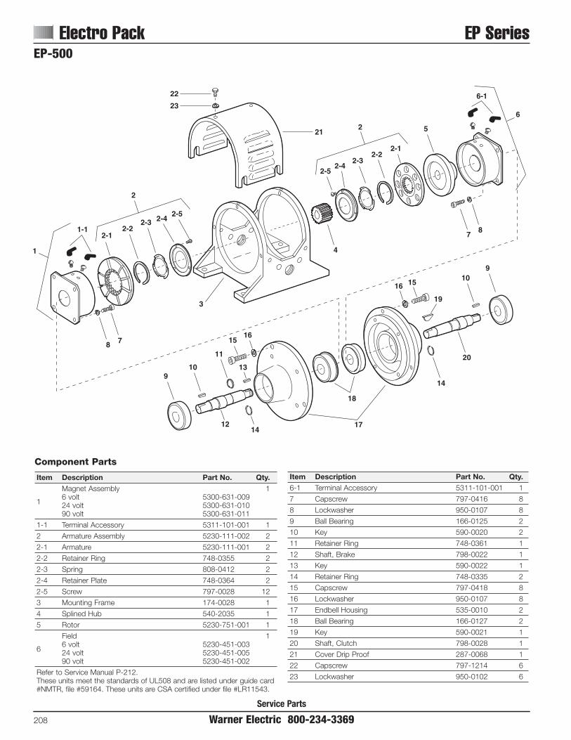
Service Parts
Electro Pack EP Series
208 Warner Electric 800-234-3369
8 7
2-12-2
22
2-42-5
1-1
23
21
20
2-52-4
2-32-2
2-1
2
2
6-1
6
14
1412
910
11
1516
13
18
17
16 15
19
109
4
3
2-3
1
78
5
EP-500
Component Parts
Item Description Part No. Qty.Magnet Assembly 1
16 volt 5300-631-00924 volt 5300-631-01090 volt 5300-631-011
1-1 Terminal Accessory 5311-101-001 1
2 Armature Assembly 5230-111-002 2
2-1 Armature 5230-111-001 2
2-2 Retainer Ring 748-0355 2
2-3 Spring 808-0412 2
2-4 Retainer Plate 748-0364 2
2-5 Screw 797-0028 12
3 Mounting Frame 174-0028 1
4 Splined Hub 540-2035 1
5 Rotor 5230-751-001 1
Field 1
66 volt 5230-451-00324 volt 5230-451-00590 volt 5230-451-002
Refer to Service Manual P-212.These units meet the standards of UL508 and are listed under guide card#NMTR, file #59164. These units are CSA certified under file #LR11543.
Item Description Part No. Qty.6-1 Terminal Accessory 5311-101-001 1
7 Capscrew 797-0416 8
8 Lockwasher 950-0107 8
9 Ball Bearing 166-0125 2
10 Key 590-0020 2
11 Retainer Ring 748-0361 1
12 Shaft, Brake 798-0022 1
13 Key 590-0022 1
14 Retainer Ring 748-0335 2
15 Capscrew 797-0418 8
16 Lockwasher 950-0107 8
17 Endbell Housing 535-0010 2
18 Ball Bearing 166-0127 2
19 Key 590-0021 1
20 Shaft, Clutch 798-0028 1
21 Cover Drip Proof 287-0068 1
22 Capscrew 797-1214 6
23 Lockwasher 950-0102 6

EP Series Electro Pack
Warner Electric 800-234-3369 209
1-1 2-3
1
2728
26
1514
1312
16
19
20 21
23
22
21 20
25 1615
14
12
13
1724
17
2-42-2
11
2-5
4
5-1
5-25-5
5-3
5-4
5-66
7
8
10 11
9
2-1
2
3
5
18
EP-825
Component Parts
Item Description Part No. Qty.Magnet Assembly 1
16 volt 5311-631-00224 volt 5311-631-00390 volt 5311-631-004
2 Armature Assembly & Splined Adapter 5321-111-001 1
2-1 Screw 797-0272 3
2-2 Autogap Accessory 5321-101-006 1
2-3 Splined Adapter 104-0008 1
2-4 Armature 5321-111-022 1
2-5 Locknut 661-0004 3
3 Frame 174-0019 1
4 Splined Hub 540-0320 1
5 Armature & Splined Adapter 5201-111-001 1
5-1 Locknut 661-0004 3
5-2 Splined Adapter 104-0008 1
5-3 Autogap Accessory 5321-101-006 1
5-4 Spacer 748-0333 3
5-5 Armature 5321-111-022 1
5-6 Screw 797-0341 3
6 Bushing, 1-1/4" Bore 180-0113 1
7 Rotor Hub 540-0013 1
8 Rotor 5201-751-003 1
Field 1
96 volt 5201-451-00624 volt 5201-451-00890 volt 5201-451-010
Item Description Part No. Qty.10 Mounting Accessory 5201-101-007 1
11 Mounting Accessory 5321-101-001 2
12 Screw 797-1008 8
13 Oil Seal 795-0023 2
14 Retainer Plate 686-0031 2
15 Ball Bearing 166-0126 2
16 Retainer Ring 748-0336 2
17 Key 590-0019 3
18 Shaft, Brake 798-0019 1
19 Retainer Ring 748-0335 1
20 Capscrew 797-0351 8
21 Lockwasher 950-0354 8
22 Endbell Housing 535-0005 2
23 Ball Bearing 166-0125 2
24 Key 590-0018 1
25 Shaft, Clutch 798-0020 1
26 Cover, Drip Proof 287-0069 1
27 Capscrew 797-1214 6
28 Lockwasher 540-0102 6
Refer to Service Manual P-212.These units meet the standards of UL508 and are listed under guide card#NMTR, file #59164. These units are CSA certified under file #LR11543.

Service Parts
Electro Pack EP Series
210 Warner Electric 800-234-3369
EP-1000
11/19/99page 123
4
6
5
14
13
15
9-3
8
16
2-3 2-42-2
3
12
11
9-1 10
9-49-69-2
7
2-5
2-1
1-3
1-2
1-1
1
9-5
18 17
1920
2122
23
2526
29
28
27
3022
21
20
19 18
17
232526 29
24
2
9

EP Series Electro PackEP-1000
Warner Electric 800-234-3369 211
Service Parts
Component Parts
Item Description Part No. Qty.Magnet Assembly 1
16 volt 5312-631-00424 volt 5312-631-00590 volt 5312-631-006
1-1 Wire Assembly 5232-954-003 1
1-2 Wire Assembly 5232-954-004 1
1-3 Terminal Accessory 5311-101-001 1
2 Armature & Splined Adapter 5322-111-002 1
2-1 Button Head Screw 797-0272 1
2-2 Autocap Accessory 5322-101-004 1
2-3 Splined Arm, Adapter 104-0009 1
2-4 Armature 5322-111-036 1
2-5 Locknut 661-0004 3
3 Frame 174-0043 1
4 Dust Cover 287-0052 1
5 Button Head Screw 797-1175 8
6 Lockwasher 950-0103 8
7 Splined Armature Hub 540-0061 1
8 Bushing, 1-7/8" Bore 180-0177 1
9 Armature & Splined Adapter 5202-111-001 1
9-1 Locknut 661-0004 3
9-2 Splined Armature Adapter 104-0009 1
9-3 Autogap Accessory 5322-101-004 1
9-4 Spacer 748-0333 3
9-5 Armature 5322-111-036 1
Item Description Part No. Qty.9-6 Cap Screw 797-0341 3
10 Bushing, 2" Bore 180-0179 1
11 Rotor Hub 540-0315 1
12 Rotor 5202-751-003 1
Field Assembly 1
136 volt 5202-451-00424 volt 5202-451-00690 volt 5202-451-007
14 Mounting Accessory 5321-101-001 1
15 Mounting Accessory 5201-101-007 1
16 Mounting Accessory 5321-101-001 1
17 Oil Seal 795-0024 2
18 Button Head Screw 797-1008 8
19 Retainer Plate 686-0047 2
20 Retainer Ring – External 748-0504 2
21 Ball Bearing 166-0130 2
22 Retainer Ring – Internal 748-0375 2
23 Key 590-0024 2
24 Shaft, Brake 798-0026 1
25 Cap Screw 797-0361 8
26 Lockwasher 950-0362 8
27 Bearing Housing 535-0012 2
28 Ball Bearing 166-0131 2
29 Key 590-0025 2
30 Shaft, Clutch 798-0025 1
Refer to Service Manual P-212.These units meet the standards of UL508 and are listed under guide card #NMTR, file #59164. These units are CSA certified under file #LR11543.
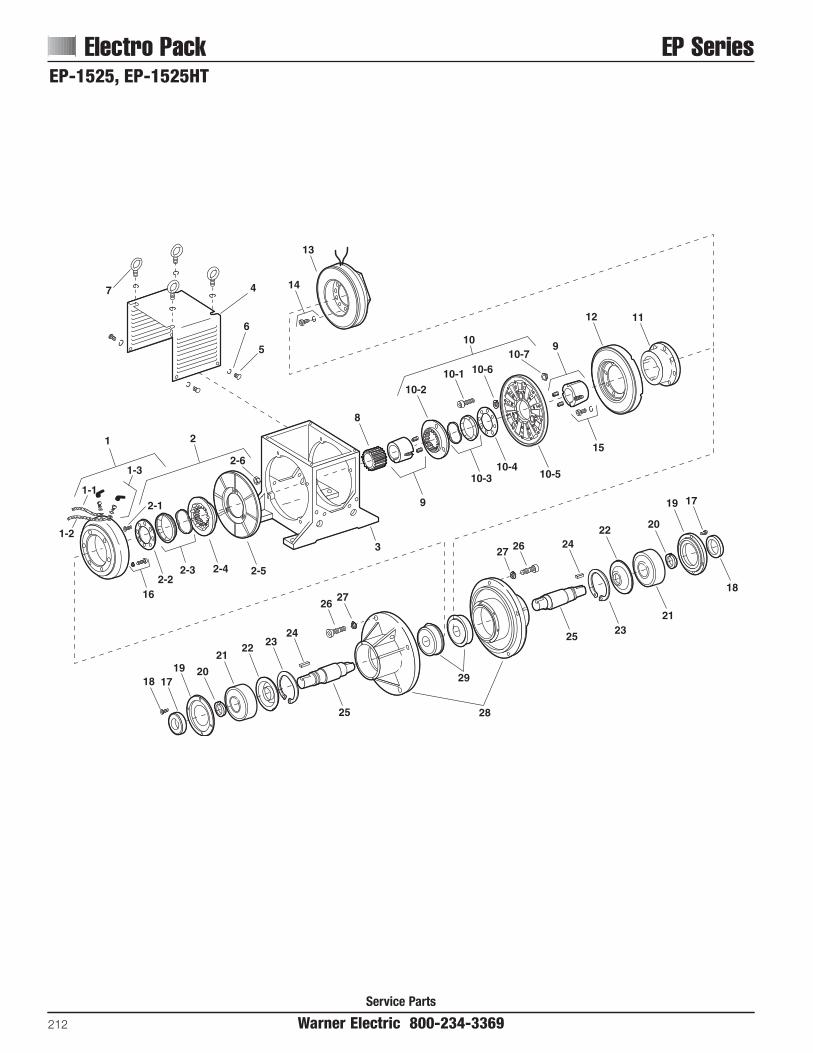
Service Parts
Electro Pack EP Series
212 Warner Electric 800-234-3369
EP-1525, EP-1525HTEP-1525 Exploded11/19/99page 126
4
6
5
15
10-3
9
16
2-4 2-5
3
1112
10-79
10-610-110-2
8
2-6
2-1
1-3
1-2
1-1
1
10-5
1819 20
2122
24
2627
29
28
2523
21
20
19 17
18
242627
25
14
13
7
2-22-3
10-4
17
23
22
2
10
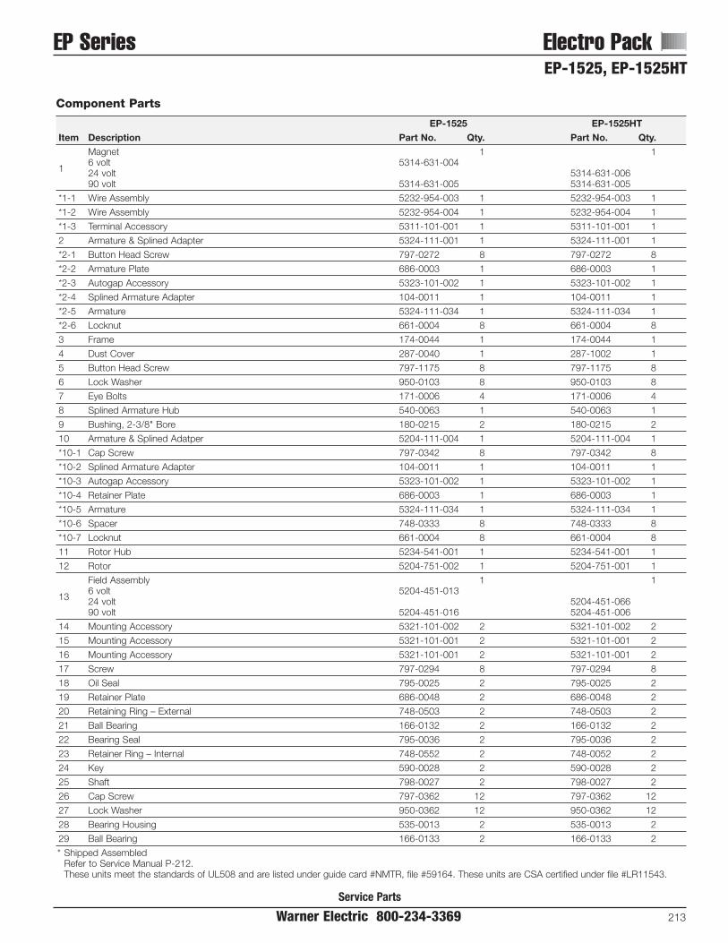
Service Parts
EP Series Electro Pack
Warner Electric 800-234-3369 213
EP-1525, EP-1525HT
Component Parts
EP-1525 EP-1525HTItem Description Part No. Qty. Part No. Qty.
Magnet 1 1
16 volt 5314-631-00424 volt 5314-631-00690 volt 5314-631-005 5314-631-005
*1-1 Wire Assembly 5232-954-003 1 5232-954-003 1
*1-2 Wire Assembly 5232-954-004 1 5232-954-004 1
*1-3 Terminal Accessory 5311-101-001 1 5311-101-001 1
2 Armature & Splined Adapter 5324-111-001 1 5324-111-001 1
*2-1 Button Head Screw 797-0272 8 797-0272 8
*2-2 Armature Plate 686-0003 1 686-0003 1
*2-3 Autogap Accessory 5323-101-002 1 5323-101-002 1
*2-4 Splined Armature Adapter 104-0011 1 104-0011 1
*2-5 Armature 5324-111-034 1 5324-111-034 1
*2-6 Locknut 661-0004 8 661-0004 8
3 Frame 174-0044 1 174-0044 1
4 Dust Cover 287-0040 1 287-1002 1
5 Button Head Screw 797-1175 8 797-1175 8
6 Lock Washer 950-0103 8 950-0103 8
7 Eye Bolts 171-0006 4 171-0006 4
8 Splined Armature Hub 540-0063 1 540-0063 1
9 Bushing, 2-3/8" Bore 180-0215 2 180-0215 2
10 Armature & Splined Adatper 5204-111-004 1 5204-111-004 1
*10-1 Cap Screw 797-0342 8 797-0342 8
*10-2 Splined Armature Adapter 104-0011 1 104-0011 1
*10-3 Autogap Accessory 5323-101-002 1 5323-101-002 1
*10-4 Retainer Plate 686-0003 1 686-0003 1
*10-5 Armature 5324-111-034 1 5324-111-034 1
*10-6 Spacer 748-0333 8 748-0333 8
*10-7 Locknut 661-0004 8 661-0004 8
11 Rotor Hub 5234-541-001 1 5234-541-001 1
12 Rotor 5204-751-002 1 5204-751-001 1
Field Assembly 1 1
136 volt 5204-451-01324 volt 5204-451-06690 volt 5204-451-016 5204-451-006
14 Mounting Accessory 5321-101-002 2 5321-101-002 2
15 Mounting Accessory 5321-101-001 2 5321-101-001 2
16 Mounting Accessory 5321-101-001 2 5321-101-001 2
17 Screw 797-0294 8 797-0294 8
18 Oil Seal 795-0025 2 795-0025 2
19 Retainer Plate 686-0048 2 686-0048 2
20 Retaining Ring – External 748-0503 2 748-0503 2
21 Ball Bearing 166-0132 2 166-0132 2
22 Bearing Seal 795-0036 2 795-0036 2
23 Retainer Ring – Internal 748-0552 2 748-0052 2
24 Key 590-0028 2 590-0028 2
25 Shaft 798-0027 2 798-0027 2
26 Cap Screw 797-0362 12 797-0362 12
27 Lock Washer 950-0362 12 950-0362 12
28 Bearing Housing 535-0013 2 535-0013 2
29 Ball Bearing 166-0133 2 166-0133 2
* Shipped AssembledRefer to Service Manual P-212.These units meet the standards of UL508 and are listed under guide card #NMTR, file #59164. These units are CSA certified under file #LR11543.

Service Parts
Electrically Released Brakes Permanent Magnet
214 Warner Electric 800-234-3369
6
1
2
34
5
7
8
9
FB-375, FB-475, FB-650

Service Parts
FB Series Electrically Released Brakes
Warner Electric 800-234-3369 215
FB-375 FB-475 FB-650Item Description Part Number Qty Part Number Qty Part Number QtyOptional Parts
1*Bushing N/A 180-0410 1/2" bore 180-0421 1/2" bore
to 180-0418 1" bore 1 to 180-0435 1-3/8" bore 1
Adapter (optional) 1 1 15/8" motor shaft 5380-101-005
27/8" motor shaft 5380-101-0041-1/8" motor shaft 5381-101-0031-3/8" motor shaft 5382-101-0031-5/8" motor shaft 5382-101-002
Service Parts
3 Retainer ring 748-0101 1 748-0102 1 748-0104 1
4 Ball bearing 166-0150 1 166-0110 1 166-0104 1
5 Retainer ring 748-0018 1 748-0002 1 748-0004 1
6 Torque arm mount assembly 5380-101-007 1 5381-101-006 1 5382-101-007 1
7 Torque arm rod assembly 5380-112-001 1 5381-112-001 1 5382-112-001 1
8 Terminal accessory 5311-101-001 1 5311-101-001 1 5311-101-001 1
9 Conduit Box 5200-101-010 1 5200-101-010 1 5200-101-010 1
*See page 235 for specific part numbers.These units, when used with the correct Warner Electric conduit box, meet the standards of UL508 and are listed under guide card #NMTR2, file#59164 and are CSA certified under file #LR11543.Magnet and armature are not field replaceable.
FB-375, FB-475, FB-650

Service Parts
Electrically Released Brakes ER Series
216 Warner Electric 800-234-3369
Inside Mounted1 2
4
4
3A-2
3A
3B
3B-2
3A-1, 3B-1
3A, 3B
5
5
Outside Mounted
ER-375, ER-475, ER-650
Component Parts
ER-375 ER-475 ER-650Item Description Part Number Qty Part Number Qty Part Number Qty
1†Bushing 180-0410-0418 1 180-0421-0435 1
(1/2" to 1" Bore) (1/2" to 1-3/8" Bore)
Hub 540-0849 1 540-0848 12 1/2" Bore 540-0846 1
5/8" Bore 540-0847 1
3AMagnet and Armature (Inside Mounted, 90 Volt)Sold only in matched pairs* 5255-5 1 5256-6 1
3A-1 Autogap Accessory 5391-101-003 4 5392-101-003 4
3A-2 Terminal Accessory 5103-101-002 1 5103-101-002 1
3BMagnet and Armature (Outside Mounted, 90 Volt)Sold only in matched pairs* 5254-1 1 5255-6 1 5256-7 1
3B-1 Autogap Accessory 5390-101-002 3 5391-101-003 4 5392-101-003 1
3B-2 Terminal Accessory 5103-101-002 1 5103-101-002 1 5103-101-002 1
Mounting Accessory4 Inside Mount 5255-101-001 1 5256-101-003 1
Outside Mount 5254-101-002 1 5255-101-002 1 5256-101-003 1
5 Conduit Box 5200-101-010 1 5200-101-010 1 5200-101-010 1
† See page 235 for specific part numbers.* Magnets and armatures sold only in pre-burnished sets to assure rated torque available upon installation.
These units, when used with the correct Warner Electric conduit box, meet the standards of UL508 and are listed under guide card #NMTR2, file #59164 and are CSA certified under file #LR11543.

Warner Electric 800-234-3369 217
ER Series Electrically Released Brakes
Service Parts
Component Parts
ER-825 ER-825 ER-1225 ER-1225Normal Duty Heavy Duty Normal Duty Heavy Duty
Item Description Part Number Qty. Part Number Qty. Part Number Qty. Part Number Qty.†Bushing 180-0137-180-0149 180-0008-180-0018 180-0262-180-0295 180-0026-180-0057
1 7/8" to1-5/8" Bore 1 7/8" to 1-1/2" Bore 1 15/16" to 3" Bore 1 3/4" to 2-11/16" Bore 1
2 Armature Hub 540-0394 1 540-0015 1
3 Splined Hub 540-0057 1 540-0064 1
4 Retainer Ring 748-0006 1 748-0005 1
5 Mounting Accessory, I.M. 5321-101-001 1 5321-101-001 1 5321-101-001 1 5321-101-001 1
6 & 7Magnet (I.M., 90 volt) and Armaturesold only in matched pairs* 5250-30 1 5250-25 1 5252-9 1 5252-4 1
6-1 Terminal Accessory 5311-101-001 1 5311-101-001 1 5311-101-001 1 5311-101-001 1
8 Autogap Accessory 5201-101-008 3 5201-101-008 4
9 Conduit Box 5200-101-010 1 5200-101-010 1 5200-101-010 1 5200-101-010 1
† See page 235 for specific part numbers.* Magnets and armatures sold only in pre-burnished sets to assure rated torque available upon installation.
These units, when used with the correct Warner Electric conduit box, meet the standards of UL508 and are listed under guide card #NMTR2, file #59164 and are CSA certified under file #LR11543.
1
1
2
34
7
7
8
6
6-1
5
9
ER-825, ER-1225
Heavy Duty
Normal Duty

Service Parts
Electrically Released Brakes UM-FBC Series
218 Warner Electric 800-234-3369
UM-1020 FBC Motor Clutch/Electrically Released Brake
2
17
16
14b
25-5
25-325-4
2
7
65
11-1
118
26
3
4
1514a
9
2125-1
20
19
23
22
25-2
24
18
13
12
10
UM-1020 FBC Exploded11/2/99page 172
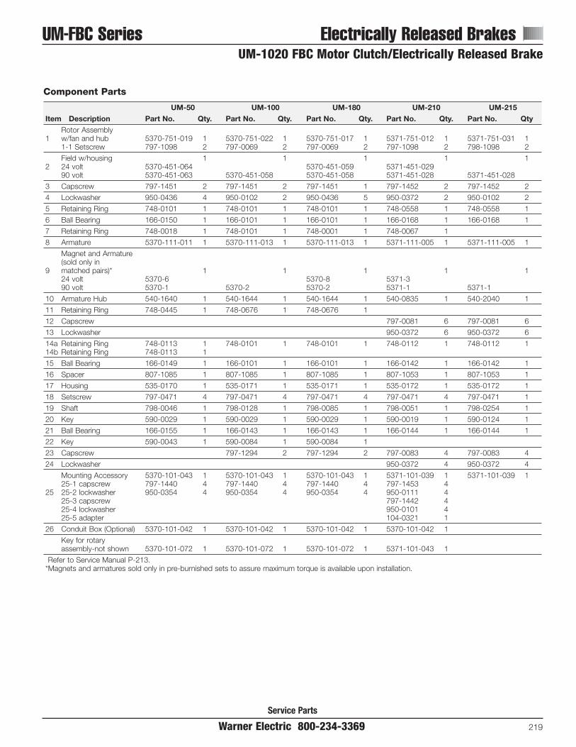
Warner Electric 800-234-3369 219
UM-FBC Series Electrically Released Brakes
Service Parts
UM-1020 FBC Motor Clutch/Electrically Released Brake
Component Parts
UM-50 UM-100 UM-180 UM-210 UM-215Item Description Part No. Qty. Part No. Qty. Part No. Qty. Part No. Qty. Part No. Qty
Rotor Assembly 1 w/fan and hub 5370-751-019 1 5370-751-022 1 5370-751-017 1 5371-751-012 1 5371-751-031 1
1-1 Setscrew 797-1098 2 797-0069 2 797-0069 2 797-1098 2 798-1098 2
Field w/housing 1 1 1 1 12 24 volt 5370-451-064 5370-451-059 5371-451-029
90 volt 5370-451-063 5370-451-058 5370-451-058 5371-451-028 5371-451-028
3 Capscrew 797-1451 2 797-1451 2 797-1451 1 797-1452 2 797-1452 2
4 Lockwasher 950-0436 4 950-0102 2 950-0436 5 950-0372 2 950-0102 2
5 Retaining Ring 748-0101 1 748-0101 1 748-0101 1 748-0558 1 748-0558 1
6 Ball Bearing 166-0150 1 166-0101 1 166-0101 1 166-0168 1 166-0168 1
7 Retaining Ring 748-0018 1 748-0101 1 748-0001 1 748-0067 1
8 Armature 5370-111-011 1 5370-111-013 1 5370-111-013 1 5371-111-005 1 5371-111-005 1
Magnet and Armature(sold only in
9 matched pairs)* 1 1 1 1 124 volt 5370-6 5370-8 5371-390 volt 5370-1 5370-2 5370-2 5371-1 5371-1
10 Armature Hub 540-1640 1 540-1644 1 540-1644 1 540-0835 1 540-2040 1
11 Retaining Ring 748-0445 1 748-0676 1 748-0676 1
12 Capscrew 797-0081 6 797-0081 6
13 Lockwasher 950-0372 6 950-0372 6
14a Retaining Ring 748-0113 1 748-0101 1 748-0101 1 748-0112 1 748-0112 114b Retaining Ring 748-0113 1
15 Ball Bearing 166-0149 1 166-0101 1 166-0101 1 166-0142 1 166-0142 1
16 Spacer 807-1085 1 807-1085 1 807-1085 1 807-1053 1 807-1053 1
17 Housing 535-0170 1 535-0171 1 535-0171 1 535-0172 1 535-0172 1
18 Setscrew 797-0471 4 797-0471 4 797-0471 4 797-0471 4 797-0471 1
19 Shaft 798-0046 1 798-0128 1 798-0085 1 798-0051 1 798-0254 1
20 Key 590-0029 1 590-0029 1 590-0029 1 590-0019 1 590-0124 1
21 Ball Bearing 166-0155 1 166-0143 1 166-0143 1 166-0144 1 166-0144 1
22 Key 590-0043 1 590-0084 1 590-0084 1
23 Capscrew 797-1294 2 797-1294 2 797-0083 4 797-0083 4
24 Lockwasher 950-0372 4 950-0372 4
Mounting Accessory 5370-101-043 1 5370-101-043 1 5370-101-043 1 5371-101-039 1 5371-101-039 125-1 capscrew 797-1440 4 797-1440 4 797-1440 4 797-1453 4
25 25-2 lockwasher 950-0354 4 950-0354 4 950-0354 4 950-0111 425-3 capscrew 797-1442 425-4 lockwasher 950-0101 425-5 adapter 104-0321 1
26 Conduit Box (Optional) 5370-101-042 1 5370-101-042 1 5370-101-042 1 5370-101-042 1
Key for rotary assembly-not shown 5370-101-072 1 5370-101-072 1 5370-101-072 1 5371-101-043 1
Refer to Service Manual P-213.*Magnets and armatures sold only in pre-burnished sets to assure maximum torque is available upon installation.

Service Parts
Electrically Released Brakes UM-FBC Series
220 Warner Electric 800-234-3369
UM-2030FBC Input Clutch/Electrically Released Brake
UM-2030 FBC Exploded11/2/99page 174
23
20
19
1815
24 3130
3332
27
29
2628
25
23
1
5
98
76
4
11
10
34
14
12
13 16
17
21b22
21a
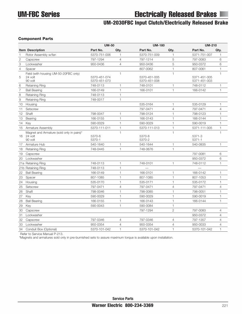
Warner Electric 800-234-3369 221
UM-FBC Series Electrically Released Brakes
Service Parts
UM-2030FBC Input Clutch/Electrically Released Brake
Component Parts
UM-50 UM-180 UM-210Item Description Part No. Qty. Part No. Qty. Part No. Qty.1 Rotor Assembly w/fan 5370-751-006 1 5370-751-009 1 5371-751-007 1
2 Capscrew 797-1294 4 797-1214 5 797-0083 6
3 Lockwasher 950-0436 4 950-0436 5 950-0372 6
4 Spacer 807-0062 1 807-0061 1
Field (with housing UM-50-20FBC only) 1 1 15 24 volt 5370-451-074 5370-451-005 5371-451-005
90 volt 5370-451-073 5370-451-008 5371-451-003
6 Retaining Ring 748-0113 1 748-0101 1 748-0112 1
7 Ball Bearing 166-0149 1 166-0101 1 166-0142 1
8 Retaining Ring 748-0113 1
9 Retaining Ring 748-0017 1
10 Housing 535-0164 1 535-0129 1
11 Setscrew 797-0471 4 797-0471 4
12 Shaft 798-0047 1 798-0124 1 798-0123 1
13 Bearing 166-0155 1 166-0143 1 166-0144 1
14 Key 590-0029 1 590-0029 1 590-0019 1
15 Armature Assembly 5370-111-011 1 5370-111-013 1 5371-111-005 1
Magnet and Armature (sold only in pairs)* 1 1 116 24 volt 5370-6 5370-8 5371-3
90 volt 5370-1 5370-2 5371-1
17 Armature Hub 540-1640 1 540-1644 1 540-0835 1
18 Retaining Ring 748-0445 1 748-0676 1
19 Capscrew 797-0081 6
20 Lockwasher 950-0372 6
21a Retaining Ring 748-0113 1 748-0101 1 748-0112 1
21b Retaining Ring 748-0113 1 — —
22 Ball Bearing 166-0149 1 166-0101 1 166-0142 1
23 Spacer 807-1085 1 807-1085 1 807-1053 1
24 Housing 535-0170 1 535-0171 1 535-0172 1
25 Setscrew 797-0471 4 797-0471 4 797-0471 4
26 Shaft 798-0046 1 798-0085 1 798-0051 1
27 Key 590-0029 1 590-0029 1 590-0019 1
28 Ball Bearing 166-0155 1 166-0143 1 166-0144 1
29 Key 590-0043 1 590-0084 1
30 Capscrew 797-1294 2 797-0083 4
31 Lockwasher 950-0372 4
32 Capscrew 797-0346 4 797-0346 4 797-1357 4
33 Lockwasher 950-0354 4 950-0354 4 950-0033 4
34 Conduit Box (Optional) 5370-101-042 1 5370-101-042 1 5370-101-042 1
Refer to Service Manual P-213.*Magnets and armatures sold only in pre-burnished sets to assure maximum torque is available upon installation.

Electrically Released Brakes EM-FBB SeriesEM-20FBB Brake Module
222 Warner Electric 800-234-3369Service Parts
Component Parts
EM-50 EM-100 EM-180 EM-210Item Description Part No. Qty. Part No. Qty. Part No. Qty. Part No. Qty.
Magnet and Armature
1 & 2(sold only in matched pairs)* 1 1 1 124 volt 5370-6 5370-8 5370-8 5371-390 volt 5370-1 5370-2 5370-2 5371-1
3 Armature Hub 540-1638 1 540-1677 1 540-1642 1 540-0741 1
4 Retaining Ring 758-0445 1 748-0676 1 748-0676 1 748-0112 1
5 Lockwasher 950-0372 6
6 Capscrew 797-0081 6
7 Retaining Ring 748-0113 2 748-0101 1 748-0101 1
8 Bearing 166-0149 1 166-0101 1 166-0101 1 166-0142 1
9 Housing 535-0130 1 535-0148 1 535-0148 1 535-0144 1
10 Setscrew 797-0471 4 797-0471 4 797-0471 4 797-0471 4
11 Shaft 5370-798-001 1 5370-798-005 1 5370-798-002 1 5371-798-001 1
12 Key 590-0029 1 590-0029 1 590-0029 1 590-0019 1
13 Bearing 166-0155 1 166-0143 1 166-0143 1 166-0144 1
14 Mounting Accessory 5370-101-017 1 5370-101-017 1 5370-101-017 1 5371-101-007 1
15 Key 590-0043 1 590-0084 1 590-0084 1
16 Capscrew 797-1214 2 797-1214 2 797-0083 2
17 Lockwasher 950-0372 2
Refer to Service Manual P-213.*Magnets and armatures sold only in pre-burnished sets to assure maximum torque is available upon installation.
65
43
7
2 1
8 7
9 10
11
14
12 13
171615

Warner Electric 800-234-3369 223
EM-MBFB Series Electrically Released Brakes
Service Parts
EM-20 MBFB Motor Brake Module
Component Parts
EM-50 EM-100 EM-180 EM-210Item Description Part No. Qty. Part No. Qty. Part No. Qty. Part No. Qty.
Magnet and Armature
1 & 2(sold only in matched pairs)* 1 1 1 124 volt 5370-6 5370-8 5370-8 5371-390 volt 5370-1 5370-2 5370-2 5371-1
3 Capscrew 797-0081 6
4 Lockwasher 950-0372 6
5 Retaining Ring 748-0445 1
6 Key 590-0043 1 590-0084 1 590-0084 1
7 Splined Hub 540-1638 1 540-1677 1 540-1642 1 540-0741 1
8 Hub 5370-541-002 1 5370-541-004 1 5370-541-003 1 5371-541-001 1
9 Retaining Ring 748-0013 2 748-0101 1 748-0101 1 748-0112 1
10 Retaining Ring 748-0676 1 748-0676 1
11 Bearing 166-0149 1 166-0101 1 166-0101 1 166-142 1
12 Housing 535-0136 1 535-0150 1 535-0150 1 535-0149 1
13 Plug 680-0028 1 680-0028 1 680-0028 1 680-0027 1
14 Setscrew 797-0471 4 797-0471 4 797-0471 4 797-0471 4
15 Mounting Accessory 5370-101-017 1 5370-101-017 1 5370-101-023 1 5371-101-007 1
16 Magnet mounting Screw 797-1214 2 797-1214 2 797-0083 2
17 Lockwasher 950-0372 2
Refer to Service Manual P-213.*Magnets and armatures sold only in pre-burnished sets to assure maximum torque is available upon installation.
34
5
7
2
1 911
108
12
14
1317
16
15
6
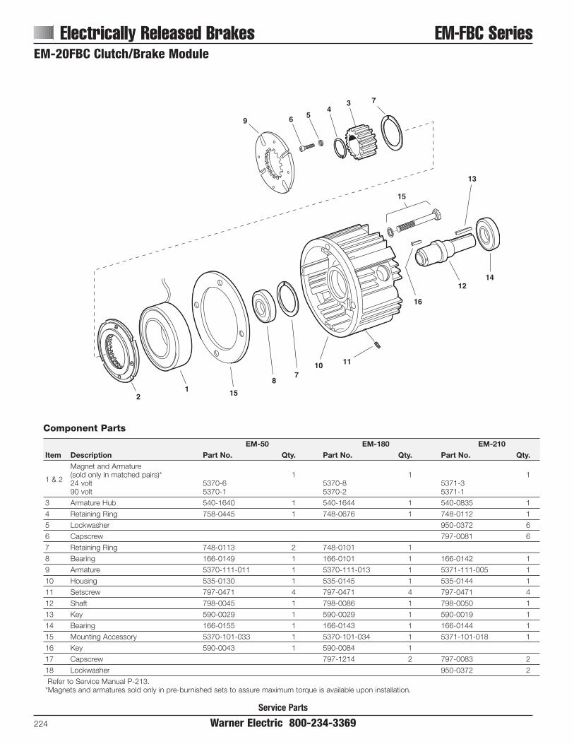
Electrically Released Brakes EM-FBC SeriesEM-20FBC Clutch/Brake Module
224 Warner Electric 800-234-3369
Component Parts
EM-50 EM-180 EM-210Item Description Part No. Qty. Part No. Qty. Part No. Qty.
Magnet and Armature
1 & 2(sold only in matched pairs)* 1 1 124 volt 5370-6 5370-8 5371-390 volt 5370-1 5370-2 5371-1
3 Armature Hub 540-1640 1 540-1644 1 540-0835 1
4 Retaining Ring 758-0445 1 748-0676 1 748-0112 1
5 Lockwasher 950-0372 6
6 Capscrew 797-0081 6
7 Retaining Ring 748-0113 2 748-0101 1
8 Bearing 166-0149 1 166-0101 1 166-0142 1
9 Armature 5370-111-011 1 5370-111-013 1 5371-111-005 1
10 Housing 535-0130 1 535-0145 1 535-0144 1
11 Setscrew 797-0471 4 797-0471 4 797-0471 4
12 Shaft 798-0045 1 798-0086 1 798-0050 1
13 Key 590-0029 1 590-0029 1 590-0019 1
14 Bearing 166-0155 1 166-0143 1 166-0144 1
15 Mounting Accessory 5370-101-033 1 5370-101-034 1 5371-101-018 1
16 Key 590-0043 1 590-0084 1
17 Capscrew 797-1214 2 797-0083 2
18 Lockwasher 950-0372 2
Refer to Service Manual P-213.*Magnets and armatures sold only in pre-burnished sets to assure maximum torque is available upon installation.
21 15
87
10 11
16
1214
13
15
9 6 54
3 7
Service Parts
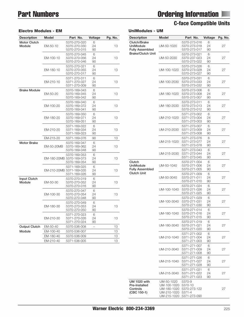
Warner Electric 800-234-3369 225
Part Numbers Ordering Information
UniModules - UM
Description Model Part No. Voltage Pg. No.Clutch/Brake 5370-273-016 6UniModule UM-50-1020 5370-273-018 24 27Fully Assembled 5370-273-017 90Brake/Clutch Unit 5370-273-021 6
UM-50-2030 5370-237-023 24 275370-273-022 90
5370-273-026 6UM-100-1020 5370-273-028 24 27
5370-273-027 90
5370-273-031 6UM-100-2030 5370-273-033 24 27
5370-273-032 90
5370-273-006 6UM-180-1020 5370-273-008 24 27
5370-273-007 90
5370-273-011 6UM-180-2030 5370-273-013 24 27
5370-273-012 90
5371-273-002 6UM-210-1020 5371-273-004 24 27
5371-273-003 90
5371-273-007 6UM-210-2030 5371-273-009 24 27
5371-273-008 90
5371-273-076 6UM-215-1020 5371-273-077 24 27
5371-273-078 90
5371-273-043 6UM-215-2030 5371-273-044 24 27
5371-273-045 90
Clutch 5370-271-004 6UniModule UM-50-1040 5370-271-006 24 27Fully Assembled 5370-271-005 90Clutch Unit 5370-271-009 6
UM-50-3040 5370-271-011 24 275370-271-010 90
5370-271-024 6UM-100-1040 5370-271-026 24 27
5370-271-025 90
5370-271-029 6UM-100-3040 5370-271-031 24 27
5370-271-030 90
5370-271-014 6UM-180-1040 5370-271-016 24 27
5370-271-015 90
5370-271-019 6UM-180-3040 5370-271-021 24 27
5370-271-020 90
5371-271-002 6UM-210-1040 5371-271-004 24 27
5371-271-003 90
5371-271-007 6UM-210-3040 5371-271-009 24 27
5371-271-008 90
5371-271-026 6UM-215-1040 5371-271-027 24 27
5371-271-028 90
5371-271-021 6UM-215-3040 5371-271-022 24 27
5371-271-023 90
UM 1020 with UM-50-1020 5370-9Pre-Installed UM-100-1020 5370-10Controls UM-180-1020 5370-273-122 27(CBC 150-1) UM-210-1020 5371-4
UM-215-1020 5371-273-090
Electro Modules - EM
Description Model Part No. Voltage Pg. No.Motor Clutch 5370-270-020 6Module EM-50-10 5370-270-030 24 13
5370-270-015 90
5370-270-045 6EM-100-10 5370-270-056 24 13
5370-270-046 90
5370-270-021 6EM-180-10 5370-270-055 24 13
5370-270-017 90
5371-270-011 6EM-210-10 5371-270-027 24 13
5371-270-009 90
Brake Module 5370-169-043 6EM-50-20 5370-169-045 24 13
5370-169-042 90
5370-169-040 6EM-100-20 5370-169-072 24 13
5370-169-041 90
5370-169-050 6EM-180-20 5370-169-071 24 13
5370-169-051 90
5371-169-022 6EM-210-20 5371-169-034 24 13
5371-169-023 90
EM-215-20 5371-169-076 90 13
Motor Brake 5370-169-047 6EM-50-20MB 5370-169-062 24 13
5370-169-048 90
5370-169-053 6EM-180-20MB 5370-169-073 24 13
5370-169-054 90
5371-169-025 6EM-210-20MB 5371-169-035 24 13
5371-169-026 90
Input Clutch 5370-270-019 6Module EM-50-30 5370-270-052 24 13
5370-270-016 90
5370-270-047 6EM-100-30 5370-270-054 24 13
5370-270-048 90
5370-270-049 6EM-180-30 5370-270-053 24 13
5370-270-050 90
5371-270-023 6EM-210-30 5371-270-026 24 13
5371-270-024 90
Output Clutch EM-50-40 5370-536-008 – 13
Module EM-100-40 5370-536-007 13
EM-180-40 5370-536-009 13
EM-210-40 5371-536-005 13
C-face Compatible Units

Accessories for EM, UM, UM-C and EUMDescription Model Part No. Voltage Pg. No.Conduit Box All Sizes 5370-101-042 13
Controls CBC-150-1 6004-448-001 110 VAC 37, 128
CBC-150-2 6004-448-002 220 VAC 37, 128
Base Mount EM/UM-50/100 5370-101-004 — 27, 37Kits EM/UM-180 5370-101-002 27, 37, 50 for 2030 and 3040 EUM-50/100/180 5370-101-012 124
EM/EUM/UM-2105371-101-001 27, 37EM/EUM/UM-215
Motor Mount EM/UM-50/100 5370-101-010 — 27Kits EM/UM-180
5370-101-012 27for 20, 1020, 1040 EUM-50/100/180
EM/EUM/UM-2105371-101-012 27EM/EUM/UM-215
Fan Kits EUM-50/1005370-101-055 37, 46for 1020 UM-50-C
EUM-1805370-101-054 37, 46UM-180-C
EUM-2105371-101-029 37, 46UM-210-C
Enclosed UniModules – Washdown Models – EUM-W
Description Model Part No. Voltage Pg. No.C-face Mount 5370-273-100 6
EUM-50-1020W 5370-273-101 24 465370-273-099 90
5370-273-108 6EUM-100-1020W 5370-273-109 24 46
5370-273-107 90
5370-273-116 6EUM-180-1020W 5370-273-117 24 46
5370-273-115 90
5371-273-056 6EUM-210-1020W 5371-273-057 24 46
5371-273-055 90
5371-273-086 6EUM-215-1020W 5371-273-087 24 46
5371-273-088 90
Base/Foot Mount 5370-273-104 6EUM-50-2030W 5370-273-105 24 46
5370-273-103 90
5370-273-120 6EUM-180-2030W 5370-273-121 24 46
5370-273-119 90
5371-273-060 6EUM-210-2030W 5371-273-061 24 46
5371-273-059 90
Accessories for EUM-WConduitBox All Sizes 5370-101-047 46
Controls CBC-150-1 6004-448-001 110 VAC 46
All Sizes CBC-150-2 6004-448-002 220 VAC 46
Base EUM-50W/180W 5370-101-047 46
Mount EUM-210W 5371-101-025 46
Motor EUM-50WMount EUM-100W 5370-101-049 46
EUM-180W
EUM-210W5371-101-026 46EUM-215W
Fan Kits EUM-50W/100W 5370-101-060 46
EUM-180W 5370-101-061 46
EUM-210W 5371-101-033 46
226 Warner Electric 800-234-3369
Ordering Information Part Numbers
UniModules – Ceramic Faced – UM-CDescription Model Part No. Voltage Pg. No.C-face Mount 5370-273-077 6
UM-50-1020-C 5370-273-078 24 375370-273-079 90
5370-273-073 6UM-180-1020-C 5370-273-074 24 37
5370-273-075 90
5371-273-035 6UM-210-1020-C 5371-273-036 24 37
5371-273-037 90
Base/Foot Mount 5370-273-085 6UM-50-2030-C 5370-273-086 24 37
5370-273-087 90
5370-273-081 6UM-180-2030-C 5370-273-082 24 37
5370-273-083 90
5371-273-039 6UM-210-2030-C 5371-273-040 24 37
5371-273-041 90
Enclosed UniModules – EUMDescription Model Part No. Voltage Pg. No.C-face Mount 5370-273-058 6
EUM-50-1020 5370-273-059 24 465370-273-057 90
EUM-50-1040 5370-271-050 90 46
5370-273-092 6EUM-100-1020 5370-273-093 24 46
5370-273-091 90
5370-273-066 6EUM-180-1020 5370-273-067 24 46
5370-273-065 90
EUM-180-1040 5370-271-051 90 46
5371-273-028 6EUM-210-1020 5371-273-029 24 46
5371-273-027 90
EUM-210-1040 5371-271-024 90 46
5371-273-082 6EUM-215-1020 5371-273-083 24 46
5371-273-084 90
Base/Foot Mount 5370-273-062 6EUM-50-2030 5370-273-063 24 46
5370-273-061 90
5370-273-070 6EUM-180-2030 5370-273-071 24 46
5370-273-069 90
5371-273-032 6EUM-210-2030 5371-273-033 24 46
5371-273-031 90
C-face Compatible Units

Adapters for Electro Brakes
Adapter No. Part Number Pg. No.
375-3/8 5380-101-005 108
375-7/8 5380-101-004 108
475-1-1/8 5381-101-003 108
650-1-3/8 5382-101-003 108
650-1-5/8 5382-101-002 108
1000-1-5/8 5384-101-008 60
1000-1-7/8 5384-101-007 60
1000-2-1/8 5384-101-010 60
1225-2-1/8 5385-101-008 60
1225-2-3/8 5383-101-007 60
Warner Electric 800-234-3369 227
Part Numbers Ordering InformationShaft Mounted Units
Electro Clutches - EC
Description Model Part No. Voltage Pg. No.EC-375 5180-271-006 6
EC-375-1/2 5180-271-004 24 535180-271-009 90
5180-271-002 6EC-375-5/8 5180-271-008 24 53
5180-271-005 90
EC-475 5181-271-004 6EC-475-5/8 5181-271-008 24 53
5181-271-007 90
5181-271-003 6EC-475-3/4 5181-271-009 24 53
5181-271-005 90
5181-271-002 6EC-475-7/8 5181-271-010 24 53
5181-271-006 90
EC-650 5281-271-004 6EC-650-1 5281-271-018 24 53
5281-271-007 90
5281-271-002 6EC-650-1-1/8 5281-271-019 24 53
5281-271-005 90
5281-271-009 6EC-650-1-1/4 5281-271-020 24 53
5281-271-008 90
5281-271-003 6EC-650-1-3/8 5281-271-016 24 53
5281-271-006 90
EC-825 5282-271-002 6EC-825-1-1/8 5282-271-008 24 53
5282-271-011 90
5282-271-003 6EC-825-1-1/4 5282-271-009 24 53
5282-271-012 90
5282-271-004 6EC-825-1-3/8 5282-271-010 24 53
5282-271-013 90
EC-1000 5283-271-002 6EC-1000-1-3/8 5283-271-010 24 53
5283-271-003 90
EC-1000-1-1/25283-271-012 24
535283-271-013 90
5283-271-004 6EC-1000-1-5/8 5283-271-011 24 53
5283-271-005 90
EC-1225 5284-271-008 6EC-1225-1-5/8 5284-271-013 24 53
5284-271-010 90
5284-271-002 6EC-1225-1-7/8 5284-271-014 24 53
5284-271-003 90
5284-271-004 6EC-1225-2-1/8 5284-271-015 24 53
5284-271-005 90
Electro Brakes - EB
Description Model Part No. Voltage Pg. No.EB-375 5380-170-005 6
EB-375-1/2 5380-170-006 24 595380-170-004 90
5380-170-003 6EB-375-5/8 5380-170-007 24 59
5380-170-002 90
EB-475 5381-170-003 6EB-475 5381-170-004 24 59
5381-170-002 90
EB-650 5382-170-003 6EB-650 5382-170-005 24 59
5382-170-002 90
EB-825 5383-170-002 6EB-825 5383-170-004 24 59
5383-170-005 90
EB-1000 5384-170-003 6EB-1000 5384-170-005 24 59
5384-170-002 90
EB-1225 5385-170-003 6EB-1225 5385-170-005 24 59
5385-170-002 90
Bushings for Electro Brakes
Bushing No. Part Number Pg. No.
1008Specify Bore Size
111180-0410 to 180-0418
1310Specify Bore Size
111180-0421 to 180-0435
H-1, H-2Specify Bore Size
111180-0002 to 180-0018
1615Specify Bore Size
111180-0131 to 180-0149
2517Specify Bore Size
111180-0185 to 180-0217

228 Warner Electric 800-234-3369
Ordering Information Part NumbersShaft Mounted UnitsAT Clutches - ATC
Description Model Part No. Voltage Pg. No.
ATC-25 5161-271-002 6ATC-25-1/2 5161-271-010 24 69
5161-271-003 90
5161-271-004 6ATC-25-5/8 5161-271-011 24 69
5161-271-005 90
5161-271-006 6ATC-25-3/4 5161-271-012 24 69
5161-271-007 90
5161-271-008 6ATC-25-7/8 5161-271-013 24 69
5161-271-009 90
ATC-55 5162-271-002 6ATC-55-3/4 5162-271-010 24 69
5162-271-003 90
5162-271-004 6ATC-55-7/8 5162-271-011 24 69
5162-271-005 90
5162-271-006 6ATC-55-1 5162-271-012 24 69
5162-271-007 90
5162-271-008 6ATC-55-1-1/8 5162-271-013 24 69
5162-271-009 90
ATC-115 5163-271-002 6ATC-115-1-1/8 5163-271-010 24 69
5163-271-003 90
5163-271-004 6ATC-115-1-1/4 5163-271-011 24 69
5163-271-005 90
5163-271-006 6ATC-115-1-3/8 5163-271-012 24 69
5163-271-007 90
5163-271-008 6ATC-115-1-1/2 5163-271-013 24 69
5163-271-009 90
Stationary Field Clutches - SFP
Description Model Part No. Voltage Pg. No.
SFP-250 5103-271-002 6SFP-250-3/8 5103-271-006 24 75
5103-271-010 90
5103-271-003 6SFP-250-7/16 5103-271-007 24 75
5103-271-011 90
5103-271-004 6SFP-250-1/2 5103-271-009 24 75
5103-271-012 90
5103-271-005 6SFP-250-5/8 5103-271-008 24 75
5103-271-013 90
AT Brakes - ATB
Description Model Part No. Voltage Pg. No.
ATB-25 5191-170-002 6ATB-25-1/2 5191-170-010 24 72
5191-170-003 90
5191-170-004 6ATB-25-5/8 5191-170-011 24 72
5191-170-005 90
5191-170-006 6ATB-25-3/4 5191-170-012 24 72
5191-170-007 90
5191-170-008 6ATB-25-7/8 5191-170-013 24 72
5191-170-009 90
ATB-55 5192-170-002 6ATB-55-3/4 5192-170-010 24 72
5192-170-003 90
5192-170-004 6ATB-55-7/8 5192-170-011 24 72
5192-170-005 90
5192-170-006 6ATB-55-1 5192-170-012 24 72
5192-170-007 90
5192-170-008 6ATB-55-1-1/8 5192-170-013 24 72
5192-170-009 90
ATB-115 5193-170-002 6ATB-115-1-1/8 5193-170-010 24 72
5193-170-003 90
5193-170-004 6ATB-115-1-1/4 5193-170-011 24 72
5193-170-005 90
5193-170-006 6ATB-115-1-3/8 5193-170-012 24 72
5193-170-007 90
5193-170-008 6ATB-115-1-1/2 5193-170-013 24 72
5193-170-009 90
Description Model Part No. Voltage Pg. No.
SFP-400 5104-271-006 6SFP-400-1/2 5104-271-016 24 75
5104-271-021 90
5104-271-007 6SFP-400-5/8 5104-271-017 24 75
5104-271-022 90
5104-271-008 6SFP-400-3/4 5104-271-018 24 75
5104-271-023 90
5104-271-009 6SFP-400-7/8 5104-271-019 24 75
5104-271-024 90
5104-271-010 6SFP-400-1 5104-271-020 24 75
5104-271-025 90

Warner Electric 800-234-3369 229
Part Numbers Ordering InformationSpring-Set Electrically Released Brakes
Electro Pack - EP
Model Part No. Voltage Pg. No.
5633-273-002 6EP-170 5633-273-003 24 77
5633-273-005 90
5130-273-031 6EP-250 5130-273-032 24 77
5130-273-034 90
5131-273-009 6EP-400 5131-273-010 24 77
5131-273-011 90
5230-273-003 6EP-500 5230-273-011 24 77
5230-273-002 90
5231-273-003 6EP-825 5231-273-004 24 77
5231-273-002 90
5232-273-003 6EP-1000 5232-273-005 24 77
5232-273-002 90
EP-15255234-273-003 6
775234-273-002 90
EP-1525HT5234-273-017 24
775234-273-012 90
Electro Pack – Ceramic Faced - EP-C
Model Part No. Voltage Pg. No.
EP-170-C5633-273-018 24
845633-273-019 90
EP-250-C5130-273-053 24
845130-273-054 90
ERS Splined Hubs - ERS
Model Bore Size Part No. Pg. No.ERS-26 .250 5158-541-006 93
.312 5158-541-007 93
.375 5158-541-008 93
ERS-42 .375 5151-541-002 93
.500 5151-541-003 93
.625 5151-541-004 93
.750 5151-541-005 93
ERS-49 .375 5155-541-002 93
.500 5155-541-003 93
.625 5155-541-004 93
.750 5155-541-005 93
.875 5155-541-006 93
ERS-57 .500 5153-541-004 93
.625 5153-541-005 93
.750 5153-541-006 93
.875 5153-541-007 93
1.000 5153-541-008 93
ERS-68 1.000 5154-541-005 93
1.125 5154-541-006 93
1.250 5154-541-007 93
1.375 5154-541-008 93
1.500 5154-541-009 93
Conduit Box 5154-101-001 93
Spring-Set Brakes (Static Holding) - ERS
Description Model Part No. Voltage Pg. No.ERS
ERS-265158-170-016 24
935158-170-015 90
ERS-425151-170-002 24
935151-170-001 90
ERS-495155-170-002 24
935155-170-001 90
ERS-575153-170-003 24
935153-170-002 90
ERS-685154-170-002 24
935154-170-001 90
ERS Mounting Flanges (Optional)
Model Part No. Pg. No.
ERS-26 686-0182 93
ERS-42 686-0183 93
ERS-49 686-0184 93
ERS-57 686-0185 93
ERS-68 686-0186 93
Spring-Set Brakes - ERD
Model Part No. Pg. No.
ERD 5 100
ERD 10 100
ERD 20 100
ERD 35 100
ERD 60 100
ERD 100 100
ERD 170 100
ERD 300 100
ERD Rectifiers ACG830A1P1 103
ACG830A1P2 103
EM/ERS Spring-Set Brake Modules
Model Part No. Voltage Pg. No.
EM-50/ERS-425370-170-122 24
965370-170-123 90
EM-50/ERS-495370-170-124 24
965370-170-125 90
EM-180/ERS-575370-170-126 24
965370-170-127 90
EM-210/ERS-685371-170-042 24
965371-170-043 90
Base Mounted Units

Accessories for UM-FBC, EUM-FBB/MBFB, andEM-FBB/FBC/MBFBDescription Model Part No. Voltage Pg. No.Conduit Box All Sizes 5370-101-042 109
Controls CBC-160-1 6013-448-001 110 VAC 129All Sizes CBC-160-2 6013-448-002 220 VAC 129
Base Mount UM-50/100 5370-101-036 — 122Kits UM-180 5370-101-037 1222030 (FB only)
UM-210 5371-101-019 122
Motor Mount EM/UM-50/100 5370-101-010 — 37, 121Kits EM/UM-180
5370-101-01237, 121
for 20FBB and EUM-50/100/1801020FBC
EM/EUM/UM-2105371-101-012
37, 121EM/EUM/UM-215
230 Warner Electric 800-234-3369
Ordering Information Part NumbersElectrically Released Brakes-PermanentMagnet
Electro Modules
Description Model Part No. Voltage Pg. No.
Brake ModuleEM-50-20FBB
5370-169-066 24133
5370-169-058 90
EM-100-20FBB5370-169-020 24
1335370-169-084 90
EM-180-20FBB5370-169-068 24
1335370-169-059 90
EM-210-20FBB5371-169-032 24
1335371-169-029 90
EM-215-20FBB5371-169-100 24
1335371-169-054 90
EM-50-20FBC5370-169-065 24
1335370-169-056 90
EM-100-20FBC5370-169-109 24
1335370-169-108 90
EM-180-20FBC5370-169-067 24
1335370-169-057 90
EM-210-20FBC5371-169-031 24
1335371-169-028 90
Motor BrakeEM-50-20MBFB
5370-169-063 24133
5370-169-060 90
EM-100-20MBFB5370-169-007 24
1335370-169-085 90
EM-180-20MBFB5370-169-069 24
1335370-169-061 90
EM-210-7/8-20MBFB5371-169-101 24
1335371-169-072 90
EM-210-20MBFB5371-169-033 24
1335371-169-030 90
Permanent Magnet Brakes (Dynamic Cycling)
Description Model Part No. Voltage Pg. No.FB
FB-375-1/25390-170-021 90
1075390-170-024 24
FB-375-5/85390-170-022 90
1075390-170-023 24
FB-4755391-170-009 90
1075391-170-012 24
FB-6505392-170-007 90
1075392-170-010 24
ER ER-375 Drawing I-25766 90 111
ER-475 Drawing I-25755 90 111
ER-650 Drawing I-25767 90 111
ER-825 (N.D.) Drawing I-25577 90 111
ER-825 (H.D.) Drawing I-25578 90 111
ER-1225 (N.D.) Drawing I-25619 36-75 111
ER-1225 (H.D.) Drawing I-25620 35-75 111
Shaft Mounted, Flange Mounted and C-face Compatible Units
UniModules - UM-FBC
Description Model Part No. Voltage Pg. No.
Clutch/BrakeUM-50-1020FBC
5370-273-037 24120
UniModules 5370-273-036 90
UM-100-1020FBC5370-273-153 24
1205370-273-125 90
UM-180-1020FBC5370-273-047 24
1205370-273-046 90
UM-210-1020FBC5371-273-013 24
1205371-273-012 90
UM-215-1020FBC5370-273-099 24
1205371-273-079 90
UM-50-2030FBC5370-273-042 24
1205370-273-041 90
UM-100-2030FBC5370-273-154 24
1205370-273-155 90
UM-180-2030FBC5370-273-052 24
1205370-273-051 90
UM-210-2030FBC5371-273-018 24
1205371-273-017 90
UM-215-2030FBC5371-273-100 24
1205371-273-101 90
Enclosed UniModules
Description Model Part No. Voltage Pg. No.
Brake EUM-50-20FBB-6 5370-169-983 90 127Module EUM-50-20FBB-10 5370-169-986 90 127
EUM-100-20FBB-12 5370-169-989 90 127
EUM-100-20-FBB-21 5370-169-992 90 127
EUM-180-20FBB-12 5370-169-995 90 127
EUM-180-20FBB-21 5370-169-998 90 127
EUM-210-20FBB-32 5371-169-078 90 127
EUM-210-20FBB-56 5371-169-082 90 127
EUM-215-20FBB-32 5371-169-086 90 127
EUM-215-20FBB-56 5371-169-090 90 127
Motor EUM-50-20MBFB-6 5370-169-965 90 127Brake EUM-50-20MBFB-10 5370-169-968 90 127
EUM-100-20MBFB-12 5370-169-971 90 127
EUM-100-20MBFB-21 5370-169-974 90 127
EUM-180-20MBFB-12 5370-169-977 90 127
EUM-180-20MBFB-21 5370-169-980 90 127
EUM-210-7/8-20MBFB-32 5371-169-064 90 127
EUM-210-7/8-20MBFB-56 5371-169-068 90 127
EUM-210-20MBFB-32 5371-169-056 90 127
EUM-210-20MBFB-56 5371-169-060 90 127

Page Model Number Part Number Service Parts Page75 SFP 250 5103-271-00275 SFP 250 5103-271-00375 SFP 250 5103-271-00475 SFP 250 5103-271-00575 SFP 250 5103-271-00675 SFP 250 5103-271-00775 SFP 250 5103-271-00875 SFP 250 5103-271-00975 SFP 250 5103-271-01075 SFP 250 5103-271-01175 SFP 250 5103-271-01275 SFP 250 5103-271-01375 SFP 400 5104-271-00675 SFP 400 5104-271-00775 SFP 400 5104-271-00875 SFP 400 5104-271-00975 SFP 400 5104-271-01075 SFP 400 5104-271-01675 SFP 400 5104-271-01775 SFP 400 5104-271-01875 SFP 400 5104-271-01975 SFP 400 5104-271-02075 SFP 400 5104-271-02175 SFP 400 5104-271-02275 SFP 400 5104-271-02375 SFP 400 5104-271-02475 SFP 400 5104-271-02577 EP250 5130-273-031 20677 EP250 5130-273-032 20677 EP250 5130-273-034 20684 EP 250C 5130-273-05384 EP 250C 5130-273-05477 EP400 5131-273-009 20677 EP400 5131-273-010 20677 EP400 5131-273-011 20693 ERS 42 5151-170-00193 ERS 42 5151-170-00293 ERS 42 5151-541-00293 ERS 42 5151-541-00393 ERS 42 5151-541-00493 ERS 42 5151-541-00593 ERS 57 5153-170-00293 ERS 57 5153-170-00393 ERS 57 5153-541-00493 ERS 57 5153-541-00593 ERS 57 5153-541-00693 ERS 57 5153-541-00793 ERS 57 5153-541-00893 ERS 68 5154-170-00193 ERS 68 5154-170-00293 ERS 68 5154-541-00593 ERS 68 5154-541-00693 ERS 68 5154-541-00793 ERS 68 5154-541-00893 ERS 68 5154-541-00993 ERS 49 5155-170-00193 ERS 49 5155-170-00293 ERS 49 5155-541-00293 ERS 49 5155-541-00393 ERS 49 5155-541-00493 ERS 49 5155-541-00593 ERS 49 5155-541-00693 ERS 26 5158-170-01593 ERS 26 5158-170-016
Page Model Number Part Number Service Parts Page93 ERS 26 5158-541-00693 ERS 26 5158-541-00793 ERS 26 5158-541-00869 ATC25 5161-271-002 20269 ATC25 5161-271-003 20269 ATC25 5161-271-004 20269 ATC25 5161-271-005 20269 ATC25 5161-271-006 20269 ATC25 5161-271-007 20269 ATC25 5161-271-008 20269 ATC25 5161-271-009 20269 ATC25 5161-271-010 20269 ATC25 5161-271-011 20269 ATC25 5161-271-012 20269 ATC25 5161-271-013 20269 ATC55 5162-271-002 20269 ATC55 5162-271-003 20269 ATC55 5162-271-004 20269 ATC55 5162-271-005 20269 ATC55 5162-271-006 20269 ATC55 5162-271-007 20269 ATC55 5162-271-008 20269 ATC55 5162-271-009 20269 ATC55 5162-271-010 20269 ATC55 5162-271-011 20269 ATC55 5162-271-012 20269 ATC55 5162-271-013 20269 ATC115 5163-271-002 20269 ATC115 5163-271-003 20269 ATC115 5163-271-004 20269 ATC115 5163-271-005 20269 ATC115 5163-271-006 20269 ATC115 5163-271-007 20269 ATC115 5163-271-008 20269 ATC115 5163-271-009 20269 ATC115 5163-271-010 20269 ATC115 5163-271-011 20269 ATC115 5163-271-012 20269 ATC115 5163-271-013 20253 EC375 5180-271-002 19053 EC375 5180-271-004 19053 EC375 5180-271-005 19053 EC375 5180-271-006 19053 EC375 5180-271-008 19053 EC375 5180-271-009 19053 EC475 5181-271-002 19053 EC475 5181-271-003 19053 EC475 5181-271-004 19053 EC475 5181-271-005 19053 EC475 5181-271-006 19053 EC475 5181-271-007 19053 EC475 5181-271-008 19053 EC475 5181-271-009 19053 EC475 5181-271-010 19072 ATB25 5191-170-002 20472 ATB25 5191-170-003 20472 ATB25 5191-170-004 20472 ATB25 5191-170-005 20472 ATB25 5191-170-006 20472 ATB25 5191-170-007 20472 ATB25 5191-170-008 20472 ATB25 5191-170-009 20472 ATB25 5191-170-010 20472 ATB25 5191-170-011 204
Service Parts
Index
Warner Electric 800-234-3369 231
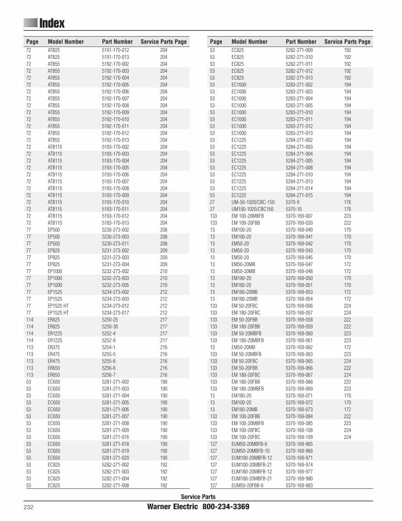
Service Parts
232 Warner Electric 800-234-3369
IndexPage Model Number Part Number Service Parts Page53 EC825 5282-271-009 19253 EC825 5282-271-010 19253 EC825 5282-271-011 19253 EC825 5282-271-012 19253 EC825 5282-271-013 19253 EC1000 5283-271-002 19453 EC1000 5283-271-003 19453 EC1000 5283-271-004 19453 EC1000 5283-271-005 19453 EC1000 5283-271-010 19453 EC1000 5283-271-011 19453 EC1000 5283-271-012 19453 EC1000 5283-271-013 19453 EC1225 5284-271-002 19453 EC1225 5284-271-003 19453 EC1225 5284-271-004 19453 EC1225 5284-271-005 19453 EC1225 5284-271-008 19453 EC1225 5284-271-010 19453 EC1225 5284-271-013 19453 EC1225 5284-271-014 19453 EC1225 5284-271-015 19427 UM-50-1020/CBC-150 5370-9 17627 UM100-1020/CBC150 5370-10 176133 EM 100-20MBFB 5370-169-007 223133 EM 100-20FBB 5370-169-020 22213 EM100-20 5370-169-040 17013 EM100-20 5370-169-041 17013 EM50-20 5370-169-042 17013 EM50-20 5370-169-043 17013 EM50-20 5370-169-045 17013 EM50-20MB 5370-169-047 17213 EM50-20MB 5370-169-048 17213 EM180-20 5370-169-050 17013 EM180-20 5370-169-051 17013 EM180-20MB 5370-169-053 17213 EM180-20MB 5370-169-054 172133 EM 50-20FBC 5370-169-056 224133 EM 180-20FBC 5370-169-057 224133 EM 50-20FBB 5370-169-058 222133 EM 180-20FBB 5370-169-059 222133 EM 50-20MBFB 5370-169-060 223133 EM 180-20MBFB 5370-169-061 22313 EM50-20MB 5370-169-062 172133 EM 50-20MBFB 5370-169-063 223133 EM 50-20FBC 5370-169-065 224133 EM 50-20FBB 5370-169-066 222133 EM 180-20FBC 5370-169-067 224133 EM 180-20FBB 5370-169-068 222133 EM 180-20MBFB 5370-169-069 22313 EM180-20 5370-169-071 17013 EM100-20 5370-169-072 17013 EM180-20MB 5370-169-073 172133 EM 100-20FBB 5370-169-084 222133 EM 100-20MBFB 5370-169-085 223133 EM 100-20FBC 5370-169-108 224133 EM 100-20FBC 5370-169-109 224127 EUM50-20MBFB-6 5370-169-965127 EUM50-20MBFB-10 5370-169-968127 EUM100-20MBFB-12 5370-169-971127 EUM100-20MBFB-21 5370-169-974127 EUM180-20MBFB-12 5370-169-977127 EUM180-20MBFB-21 5370-169-980127 EUM50-20FBB-6 5370-169-983
Page Model Number Part Number Service Parts Page72 ATB25 5191-170-012 20472 ATB25 5191-170-013 20472 ATB55 5192-170-002 20472 ATB55 5192-170-003 20472 ATB55 5192-170-004 20472 ATB55 5192-170-005 20472 ATB55 5192-170-006 20472 ATB55 5192-170-007 20472 ATB55 5192-170-008 20472 ATB55 5192-170-009 20472 ATB55 5192-170-010 20472 ATB55 5192-170-011 20472 ATB55 5192-170-012 20472 ATB55 5192-170-013 20472 ATB115 5193-170-002 20472 ATB115 5193-170-003 20472 ATB115 5193-170-004 20472 ATB115 5193-170-005 20472 ATB115 5193-170-006 20472 ATB115 5193-170-007 20472 ATB115 5193-170-008 20472 ATB115 5193-170-009 20472 ATB115 5193-170-010 20472 ATB115 5193-170-011 20472 ATB115 5193-170-012 20472 ATB115 5193-170-013 20477 EP500 5230-273-002 20877 EP500 5230-273-003 20877 EP500 5230-273-011 20877 EP825 5231-273-002 20977 EP825 5231-273-003 20977 EP825 5231-273-004 20977 EP1000 5232-273-002 21077 EP1000 5232-273-003 21077 EP1000 5232-273-005 21077 EP1525 5234-273-002 21277 EP1525 5234-273-003 21277 EP1525 HT 5234-273-012 21277 EP1525 HT 5234-273-017 212114 ER825 5250-25 217114 ER825 5250-30 217114 ER1225 5252-4 217114 ER1225 5252-9 217113 ER375 5254-1 216113 ER475 5255-5 216113 ER475 5255-6 216113 ER650 5256-6 216113 ER650 5256-7 21653 EC650 5281-271-002 19053 EC650 5281-271-003 19053 EC650 5281-271-004 19053 EC650 5281-271-005 19053 EC650 5281-271-006 19053 EC650 5281-271-007 19053 EC650 5281-271-008 19053 EC650 5281-271-009 19053 EC650 5281-271-016 19053 EC650 5281-271-018 19053 EC650 5281-271-019 19053 EC650 5281-271-020 19053 EC825 5282-271-002 19253 EC825 5282-271-003 19253 EC825 5282-271-004 19253 EC825 5282-271-008 192

Page Model Number Part Number Service Parts Page27 UM 100-2030 5370-273-031 18027 UM 100-2030 5370-273-032 18027 UM 100-2030 5370-273-033 180120 UM 50-1020FBC 5370-273-036 218120 UM 50-1020FBC 5370-273-037 218120 UM 50-2030FBC 5370-273-041 220120 UM 50-2030FBC 5370-273-042 220120 UM 180-1020FBC 5370-273-046 218120 UM 180-1020FBC 5370-273-047 218120 UM 180-2030FBC 5370-273-051 220120 UM 180-2030FBC 5370-273-052 22046 EUM 50-1020 5370-273-057 18446 EUM 50-1020 5370-273-058 18446 EUM 50-1020 5370-273-059 18446 EUM 50-2030 5370-273-061 18846 EUM 50-2030 5370-273-062 18846 EUM 50-2030 5370-273-063 18846 EUM180-1020 5370-273-065 18446 EUM180-1020 5370-273-066 18446 EUM180-1020 5370-273-067 18446 EUM180-2030 5370-273-069 18846 EUM180-2030 5370-273-070 18846 EUM180-2030 5370-273-071 18837 UM 180-1020C 5370-273-07337 UM 180-1020C 5370-273-07437 UM 180-1020C 5370-273-07537 UM 50-1020C 5370-273-07737 UM 50-1020C 5370-273-07837 UM 50-1020C 5370-273-07937 UM 180-2030C 5370-273-08137 UM 180-2030C 5370-273-08237 UM 180-2030C 5370-273-08337 UM 50-2030C 5370-273-08537 UM 50-2030C 5370-273-08637 UM 50-2030C 5370-273-08746 EUM100-1020 5370-273-091 18446 EUM100-1020 5370-273-092 18446 EUM100-1020 5370-273-093 18446 EUM 50-1020W 5370-273-099 18446 EUM 50-1020W 5370-273-100 18446 EUM 50-1020W 5370-273-101 18446 EUM 50-2030W 5370-273-103 18846 EUM 50-2030W 5370-273-104 18846 EUM 50-2030W 5370-273-105 18846 EUM100-1020W 5370-273-107 18446 EUM100-1020W 5370-273-108 18446 EUM100-1020W 5370-273-109 18446 EUM180-1020W 5370-273-115 18446 EUM180-1020W 5370-273-116 18446 EUM180-1020W 5370-273-117 18446 EUM180-2030W 5370-273-119 18846 EUM180-2030W 5370-273-120 18846 EUM180-2030W 5370-273-121 18827 UM 180-1020/CBC150 5370-273-122 176120 UM 100-1020FBC 5370-273-125 218120 UM 100-1020FBC 5370-273-153 218120 UM 100-2030FBC 5370-273-154 218120 UM 100-2030FBC 5370-273-155 21813 EM100-40 5370-536-007 17513 EM 50-40 5370-536-008 17513 EM180-40 5370-536-009 17527 UM 50-1020/CBC150 5370-9 17613 EM 210-20 5371-169-022 17013 EM 210-20 5371-169-023 170
Page Model Number Part Number Service Parts Page127 EUM50-20FBB-10 5370-169-986127 EUM100-20FBB-12 5370-169-989127 EUM-100-20FBB-21 5370-169-992127 EUM180-20FBB-12 5370-169-995127 EUM180-20FBB-21 5370-169-99896 EM 50/ERS-42 5370-170-12296 EM 50/ERS-42 5370-170-12396 EM 50/ERS-49 5370-170-12496 EM 50/ERS-49 5370-170-12596 EM 180/ERS-57 5370-170-12696 EM 180/ERS-57 5370-170-12713 EM50-10 5370-270-015 16913 EM50-30 5370-270-016 17413 EM180-10 5370-270-017 16913 EM50-30 5370-270-019 17413 EM50-10 5370-270-020 16913 EM180-10 5370-270-021 16913 EM50-10 5370-270-030 16913 EM100-10 5370-270-045 16913 EM100-10 5370-270-046 16913 EM100-30 5370-270-047 17413 EM100-30 5370-270-048 17413 EM180-30 5370-270-049 17413 EM180-30 5370-270-050 17413 EM 50-30 5370-270-052 17413 EM180-30 5370-270-053 17413 EM100-30 5370-270-054 17413 EM180-10 5370-270-055 16913 EM100-10 5370-270-056 16927 UM 50-1040 5370-271-004 17827 UM 50-1040 5370-271-005 17827 UM 50-1040 5370-271-006 17827 UM 50-3040 5370-271-009 18227 UM 50-3040 5370-271-010 18227 UM 50-3040 5370-271-011 18227 UM180-1040 5370-271-014 17827 UM180-1040 5370-271-015 17827 UM180-1040 5370-271-016 17827 UM180-3040 5370-271-019 18227 UM180-3040 5370-271-020 18227 UM180-3040 5370-271-021 18227 UM100-1040 5370-271-024 17827 UM100-1040 5370-271-025 17827 UM100-1040 5370-271-026 17827 UM100-3040 5370-271-029 18227 UM100-3040 5370-271-030 18227 UM100-3040 5370-271-031 18246 EUM 50-1040 5370-271-050 18646 EUM180-1040 5370-271-051 18627 UM 180-1020 5370-273-006 17627 UM 180-1020 5370-273-007 17627 UM 180-1020 5370-273-008 17627 UM 180-2030 5370-273-011 18027 UM 180-2030 5370-273-012 18027 UM 180-2030 5370-273-013 18027 UM 50-1020 5370-273-016 17627 UM 50-1020 5370-273-017 17627 UM 50-1020 5370-273-018 17627 UM 50-2030 5370-273-021 18027 UM 50-2030 5370-273-022 18027 UM 50-2030 5370-273-023 18027 UM 100-1020 5370-273-026 17627 UM 100-1020 5370-273-027 17627 UM 100-1020 5370-273-028 176
Index
Warner Electric 800-234-3369 233
Service Parts

Packaged Products
234 Warner Electric 800-234-3369
Service Parts
Page Model Number Part Number Service Parts Page37 UM 210-2030C 5371-273-04037 UM 210-2030C 5371-273-04127 UM215-2030 5371-273-043 18027 UM215-2030 5371-273-044 18027 UM215-2030 5371-273-045 18046 EUM210-1020W 5371-273-055 18446 EUM210-1020W 5371-273-056 18446 EUM210-1020W 5371-273-057 18446 EUM210-2030W 5371-273-059 18846 EUM210-2030W 5371-273-060 18846 EUM210-2030W 5371-273-061 18827 UM215-1020 5371-273-076 17627 UM215-1020 5371-273-077 17627 UM215-1020 5371-273-078 176120 UM215-1020FBC 5371-273-07946 EUM215-1020 5371-273-082 18446 EUM215-1020 5371-273-083 18446 EUM215-1020 5371-273-084 18446 EUM215-1020W 5371-273-086 18446 EUM215-1020W 5371-273-087 18446 EUM215-1020W 5371-273-088 18427 UM215-1020/CBC150 5371-273-090 176120 UM 215-2030FBC 5371-273-100 218120 UM 215-2030FBC 5371-273-101 21827 UM210-1020/CBC150 5371-4 17613 EM210-40 5371-536-005 17546 EUM210-1020W 5371-273-055 18459 EB375 5380-170-002 19659 EB375 5380-170-003 19659 EB375 5380-170-004 19659 EB375 5380-170-005 19659 EB375 5380-170-006 19659 EB375 5380-170-007 19659 EB475 5381-170-002 19659 EB475 5381-170-003 19659 EB475 5381-170-004 19659 EB650 5382-170-002 19659 EB650 5382-170-003 19659 EB650 5382-170-005 19659 EB825 5383-170-002 19859 EB825 5383-170-004 19859 EB825 5383-170-005 19859 EB1000 5384-170-002 20059 EB1000 5384-170-003 20059 EB1000 5384-170-005 20059 EB1225 5385-170-002 20059 EB1225 5385-170-003 20059 EB1225 5385-170-005 200107 FB375 5390-170-021 214107 FB375 5390-170-022 214107 FB375 5390-170-023 214107 FB375 5390-170-024 214107 FB475 5391-170-009 214107 FB475 5391-170-012 214107 FB650 5392-170-007 214107 FB650 5392-170-010 21477 EP170 5633-273-002 20677 EP170 5633-273-003 20677 EP170 5633-273-005 20684 EP 170C 5633-273-01884 EP 170C 5633-273-019
Page Model Number Part Number Service Parts Page13 EM 210-20MB 5371-169-025 17213 EM 210-20MB 5371-169-026 172133 EM 210-20FBC 5371-169-028 224133 EM 210-20FBB 5371-169-029 222133 EM 210-20MBFB 5371-169-030 223133 EM 210-20FBC 5371-169-031 224133 EM 210-20FBB 5371-169-032 222133 EM 210-20MBFB 5371-169-033 22313 EM 210-20 5371-169-034 17013 EM 210-20MB 5371-169-035 172133 EM 215-20FBB 5371-169-054 222127 EUM 210-20MBFB-32 5371-169-056127 EUM 210-20MBFB-56 5371-169-060127 EUM 210-7/8-20MBFB-32 5371-169-064127 EUM 210-7/8-20MBFB-56 5371-169-068133 EM 210-7/8-20MBFB 5371-169-072 22313 EM 215-20 5371-169-076 170127 EUM 210-20FBB-32 5371-169-078127 EUM 210-20FBB-56 5371-169-082127 EUM 215-20FBB-32 5371-169-086127 EUM 215-20FBB-56 5371-169-090133 EM 215-20FBB 5371-169-100 222133 EM 210-7/8-20MBFB 5371-169-101 22396 EM 210/ERS-68 5371-170-04296 EM 210/ERS-68 5371-170-04313 EM 210-10 5371-270-009 16913 EM 210-10 5371-270-011 16913 EM 210-30 5371-270-023 17413 EM 210-30 5371-270-024 17413 EM 210-30 5371-270-026 17413 EM 210-10 5371-270-027 16927 UM 210-1040 5371-271-002 17827 UM 210-1040 5371-271-003 17827 UM 210-1040 5371-271-004 17827 UM210-3040 5371-271-007 18227 UM210-3040 5371-271-008 18227 UM210-3040 5371-271-009 18227 UM215-3040 5371-271-021 18227 UM215-3040 5371-271-022 18227 UM215-3040 5371-271-023 18246 EUM210-1040 5371-271-024 18627 UM215-1040 5371-271-026 17827 UM215-1040 5371-271-027 17827 UM215-1040 5371-271-028 17827 UM210-1020 5371-273-002 17627 UM210-1020 5371-273-003 17627 UM210-1020 5371-273-004 17627 UM210-2030 5371-273-007 18027 UM210-2030 5371-273-008 18027 UM210-2030 5371-273-009 180120 UM210-1020FBC 5371-273-012 218120 UM210-1020FBC 5371-273-013 218120 UM210-2030FBC 5371-273-017 220120 UM210-2030FBC 5371-273-018 22046 EUM210-1020 5371-273-027 18446 EUM210-1020 5371-273-028 18446 EUM210-1020 5371-273-029 18446 EUM210-2030 5371-273-031 18846 EUM210-2030 5371-273-032 18846 EUM210-2030 5371-273-033 18837 UM 210-1020C 5371-273-03537 UM 210-1020C 5371-273-03637 UM 210-1020C 5371-273-03737 UM 210-2030C 5371-273-039
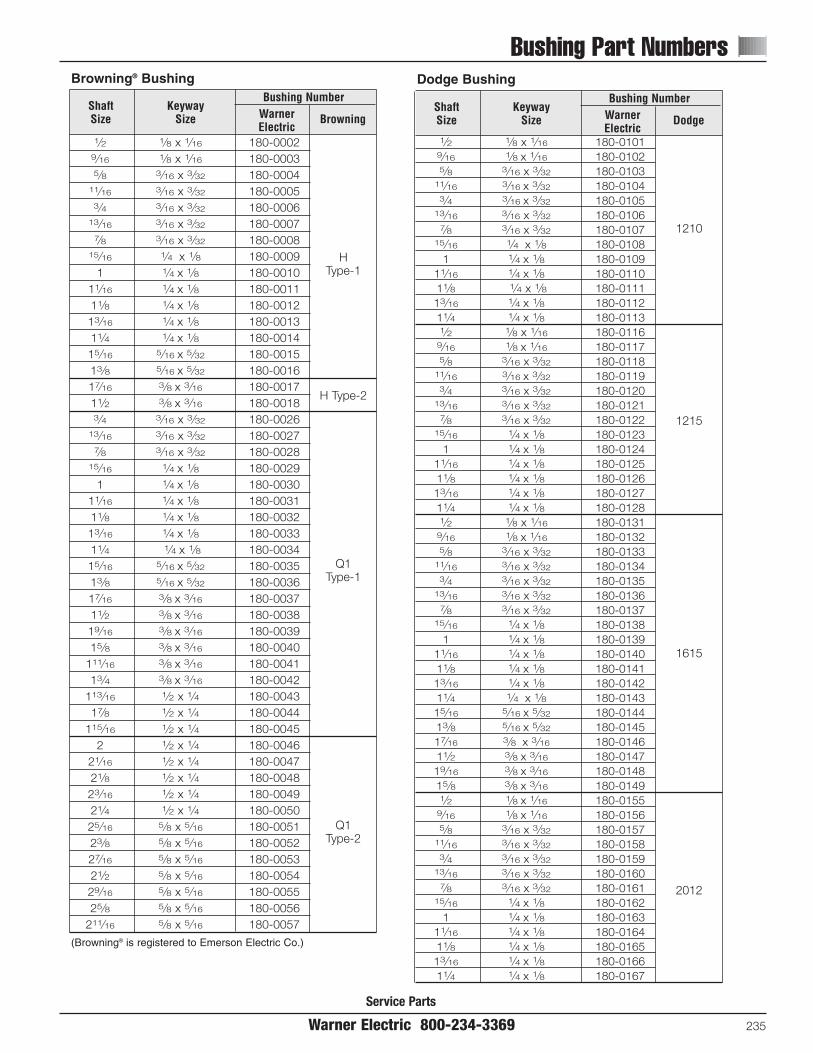
Bushing Part Numbers
Warner Electric 800-234-3369 235
Service Parts
1⁄2 1⁄8 x 1⁄16 180-00029⁄16 1⁄8 x 1⁄16 180-00035⁄8 3⁄16 x 3⁄32 180-0004
11⁄16 3⁄16 x 3⁄32 180-00053⁄4 3⁄16 x 3⁄32 180-0006
13⁄16 3⁄16 x 3⁄32 180-00077⁄8 3⁄16 x 3⁄32 180-0008
15⁄16 1⁄4 x 1⁄8 180-00091 1⁄4 x 1⁄8 180-0010
11⁄16 1⁄4 x 1⁄8 180-001111⁄8 1⁄4 x 1⁄8 180-001213⁄16 1⁄4 x 1⁄8 180-001311⁄4 1⁄4 x 1⁄8 180-001415⁄16 5⁄16 x 5⁄32 180-001513⁄8 5⁄16 x 5⁄32 180-001617⁄16 3⁄8 x 3⁄16 180-001711⁄2 3⁄8 x 3⁄16 180-00183⁄4 3⁄16 x 3⁄32 180-0026
13⁄16 3⁄16 x 3⁄32 180-00277⁄8 3⁄16 x 3⁄32 180-0028
15⁄16 1⁄4 x 1⁄8 180-00291 1⁄4 x 1⁄8 180-0030
11⁄16 1⁄4 x 1⁄8 180-003111⁄8 1⁄4 x 1⁄8 180-003213⁄16 1⁄4 x 1⁄8 180-003311⁄4 1⁄4 x 1⁄8 180-003415⁄16 5⁄16 x 5⁄32 180-003513⁄8 5⁄16 x 5⁄32 180-003617⁄16 3⁄8 x 3⁄16 180-003711⁄2 3⁄8 x 3⁄16 180-003819⁄16 3⁄8 x 3⁄16 180-003915⁄8 3⁄8 x 3⁄16 180-0040
111⁄16 3⁄8 x 3⁄16 180-004113⁄4 3⁄8 x 3⁄16 180-0042
113⁄16 1⁄2 x 1⁄4 180-004317⁄8 1⁄2 x 1⁄4 180-0044
115⁄16 1⁄2 x 1⁄4 180-0045 2 1⁄2 x 1⁄4 180-0046
21⁄16 1⁄2 x 1⁄4 180-004721⁄8 1⁄2 x 1⁄4 180-004823⁄16 1⁄2 x 1⁄4 180-004921⁄4 1⁄2 x 1⁄4 180-005025⁄16 5⁄8 x 5⁄16 180-005123⁄8 5⁄8 x 5⁄16 180-005227⁄16 5⁄8 x 5⁄16 180-005321⁄2 5⁄8 x 5⁄16 180-005429⁄16 5⁄8 x 5⁄16 180-005525⁄8 5⁄8 x 5⁄16 180-0056
211⁄16 5⁄8 x 5⁄16 180-0057
Shaft Size
KeywaySize
Bushing NumberWarnerElectric
Browning
H Type-1
H Type-2
Q1Type-1
Q1 Type-2
1⁄2 1⁄8 x 1⁄16 180-01019⁄16 1⁄8 x 1⁄16 180-01025⁄8 3⁄16 x 3⁄32 180-0103
11⁄16 3⁄16 x 3⁄32 180-01043⁄4 3⁄16 x 3⁄32 180-0105
13⁄16 3⁄16 x 3⁄32 180-01067⁄8 3⁄16 x 3⁄32 180-0107
15⁄16 1⁄4 x 1⁄8 180-01081 1⁄4 x 1⁄8 180-0109
11⁄16 1⁄4 x 1⁄8 180-011011⁄8 1⁄4 x 1⁄8 180-011113⁄16 1⁄4 x 1⁄8 180-011211⁄4 1⁄4 x 1⁄8 180-01131⁄2 1⁄8 x 1⁄16 180-0116
9⁄16 1⁄8 x 1⁄16 180-01175⁄8 3⁄16 x 3⁄32 180-0118
11⁄16 3⁄16 x 3⁄32 180-01193⁄4 3⁄16 x 3⁄32 180-0120
13⁄16 3⁄16 x 3⁄32 180-01217⁄8 3⁄16 x 3⁄32 180-0122
15⁄16 1⁄4 x 1⁄8 180-01231 1⁄4 x 1⁄8 180-0124
11⁄16 1⁄4 x 1⁄8 180-012511⁄8 1⁄4 x 1⁄8 180-012613⁄16 1⁄4 x 1⁄8 180-012711⁄4 1⁄4 x 1⁄8 180-01281⁄2 1⁄8 x 1⁄16 180-0131
9⁄16 1⁄8 x 1⁄16 180-01325⁄8 3⁄16 x 3⁄32 180-0133
11⁄16 3⁄16 x 3⁄32 180-01343⁄4 3⁄16 x 3⁄32 180-0135
13⁄16 3⁄16 x 3⁄32 180-01367⁄8 3⁄16 x 3⁄32 180-0137
15⁄16 1⁄4 x 1⁄8 180-01381 1⁄4 x 1⁄8 180-0139
11⁄16 1⁄4 x 1⁄8 180-014011⁄8 1⁄4 x 1⁄8 180-014113⁄16 1⁄4 x 1⁄8 180-014211⁄4 1⁄4 x 1⁄8 180-014315⁄16 5⁄16 x 5⁄32 180-014413⁄8 5⁄16 x 5⁄32 180-014517⁄16 3⁄8 x 3⁄16 180-014611⁄2 3⁄8 x 3⁄16 180-014719⁄16 3⁄8 x 3⁄16 180-014815⁄8 3⁄8 x 3⁄16 180-01491⁄2 1⁄8 x 1⁄16 180-0155
9⁄16 1⁄8 x 1⁄16 180-01565⁄8 3⁄16 x 3⁄32 180-0157
11⁄16 3⁄16 x 3⁄32 180-01583⁄4 3⁄16 x 3⁄32 180-0159
13⁄16 3⁄16 x 3⁄32 180-01607⁄8 3⁄16 x 3⁄32 180-0161
15⁄16 1⁄4 x 1⁄8 180-01621 1⁄4 x 1⁄8 180-0163
11⁄16 1⁄4 x 1⁄8 180-016411⁄8 1⁄4 x 1⁄8 180-016513⁄16 1⁄4 x 1⁄8 180-016611⁄4 1⁄4 x 1⁄8 180-0167
Shaft Size
KeywaySize
Bushing NumberWarnerElectric
Dodge
1210
1215
1615
2012
Dodge BushingBrowning® Bushing
(Browning® is registered to Emerson Electric Co.)

Bushing Part Numbers
236 Warner Electric 800-234-3369Service Parts
15⁄16 5⁄16 x 5⁄32 180-016813⁄8 5⁄16 x 5⁄32 180-016917⁄16 3⁄8 x 3⁄16 180-017011⁄2 3⁄8 x 3⁄16 180-017119⁄16 3⁄8 x 3⁄16 180-017215⁄8 3⁄8 x 3⁄16 180-0173
111⁄16 3⁄8 x 3⁄16 180-017413⁄4 3⁄8 x 3⁄16 180-0175
113⁄16 1⁄2 x 1⁄4 180-017617⁄8 1⁄2 x 1⁄4 180-0177
115⁄16 1⁄2 x 1⁄4 180-01782 1⁄2 x 1⁄4 180-0179
1⁄2 1⁄8 x 1⁄16 180-01859⁄16 1⁄8 x 1⁄16 180-01865⁄8 3⁄16 x 3⁄32 180-0187
11⁄16 3⁄16 x 3⁄32 180-01883⁄4 3⁄16 x 3⁄32 180-0189
13⁄16 3⁄16 x 3⁄32 180-01907⁄8 3⁄16 x 3⁄32 180-0191
15⁄16 1⁄4 x 1⁄8 180-01921 1⁄4 x 1⁄8 180-0193
11⁄16 1⁄4 x 1⁄8 180-019411⁄8 1⁄4 x 1⁄8 180-019513⁄16 1⁄4 x 1⁄8 180-019611⁄4 1⁄4 x 1⁄8 180-019715⁄16 5⁄16 x 5⁄32 180-019813⁄8 5⁄16 x 5⁄32 180-019917⁄16 3⁄8 x 3⁄16 180-020011⁄2 3⁄8 x 3⁄16 180-020119⁄16 3⁄8 x 3⁄16 180-020215⁄8 3⁄8 x 3⁄16 180-0203
111⁄16 3⁄8 x 3⁄16 180-020413⁄4 3⁄8 x 3⁄16 180-0205
113⁄16 1⁄2 x 1⁄4 180-020617⁄8 1⁄2 x 1⁄4 180-0207
115⁄16 1⁄2 x 1⁄4 180-02082 1⁄2 x 1⁄4 180-0209
21⁄16 1⁄2 x 1⁄4 180-021021⁄8 1⁄2 x 1⁄4 180-021123⁄16 1⁄2 x 1⁄4 180-021221⁄4 1⁄2 x 1⁄4 180-021325⁄16 5⁄8 x 5⁄16 180-021423⁄8 5⁄8 x 5⁄16 180-021527⁄16 5⁄8 x 5⁄16 180-021621⁄2 5⁄8 x 5⁄16 180-021715⁄16 1⁄4 x 1⁄8 180-0223
1 1⁄4 x 1⁄8 180-022411⁄16 1⁄4 x 1⁄8 180-022511⁄8 1⁄4 x 1⁄8 180-022613⁄16 1⁄4 x 1⁄8 180-022711⁄4 1⁄4 x 1⁄8 180-022815⁄16 5⁄16 x 5⁄32 180-022913⁄8 5⁄16 x 5⁄32 180-023017⁄16 3⁄8 x 3⁄16 180-023111⁄2 3⁄8 x 3⁄16 180-023219⁄16 3⁄8 x 3⁄16 180-023315⁄8 3⁄8 x 3⁄16 180-0234
Shaft Size
KeywaySize
Bushing NumberWarnerElectric
Dodge
2012
2517
3020
111⁄16 3⁄8 x 3⁄16 180-023513⁄4 3⁄8 x 3⁄16 180-0236
113⁄16 1⁄2 x 1⁄4 180-023717⁄8 1⁄2 x 1⁄4 180-0238
115⁄16 1⁄2 x 1⁄4 180-02392 1⁄2 x 1⁄4 180-0240
21⁄16 1⁄2 x 1⁄4 180-024121⁄8 1⁄2 x 1⁄4 180-024223⁄16 1⁄2 x 1⁄4 180-024321⁄4 1⁄2 x 1⁄4 180-024425⁄16 5⁄8 x 5⁄16 180-024523⁄8 5⁄8 x 5⁄16 180-024627⁄16 5⁄8 x 5⁄16 180-024721⁄2 5⁄8 x 5⁄16 180-024829⁄16 5⁄8 x 5⁄16 180-024925⁄8 5⁄8 x 5⁄16 180-0250
211⁄16 5⁄8 x 5⁄16 180-025123⁄4 5⁄8 x 5⁄16 180-0252
213⁄16 3⁄4 x 3⁄8 180-025327⁄8 3⁄4 x 3⁄8 180-0254
215⁄16 3⁄4 x 3⁄8 180-02553 3⁄4 x 3⁄8 180-0256
15⁄16 1⁄4 x 1⁄8 180-02621 1⁄4 x 1⁄8 180-0263
11⁄16 1⁄4 x 1⁄8 180-026411⁄8 1⁄4 x 1⁄8 180-026513⁄16 1⁄4 x 1⁄8 180-026611⁄4 1⁄4 x 1⁄8 180-026715⁄16 5⁄16 x 5⁄32 180-026813⁄8 5⁄16 x 5⁄32 180-026917⁄16 3⁄8 x 3⁄16 180-027011⁄2 3⁄8 x 3⁄16 180-027119⁄16 3⁄8 x 3⁄16 180-027215⁄8 3⁄8 x 3⁄16 180-0273
111⁄16 3⁄8 x 3⁄16 180-027413⁄4 3⁄8 x 3⁄16 180-0275
113⁄16 1⁄2 x 1⁄4 180-027617⁄8 1⁄2 x 1⁄4 180-0277
115⁄16 1⁄2 x 1⁄4 180-02782 1⁄2 x 1⁄4 180-0279
21⁄16 1⁄2 x 1⁄4 180-028021⁄8 1⁄2 x 1⁄4 180-028123⁄16 1⁄2 x 1⁄4 180-028221⁄4 1⁄2 x 1⁄4 180-0283
215⁄16 5⁄8 x 5⁄16 180-028423⁄8 5⁄8 x 5⁄16 180-028527⁄16 5⁄8 x 5⁄16 180-028621⁄2 5⁄8 x 5⁄16 180-028729⁄16 5⁄8 x 5⁄16 180-028825⁄8 5⁄8 x 5⁄16 180-0289
211⁄16 5⁄8 x 5⁄16 180-029023⁄4 5⁄8 x 5⁄16 180-0291
213⁄16 3⁄4 x 3⁄8 180-029227⁄8 3⁄4 x 3⁄8 180-0293
215⁄16 3⁄4 x 3⁄8 180-02943 3⁄4 x 3⁄8 180-0295
Shaft Size
KeywaySize
Bushing NumberWarnerElectric
Dodge
3020
3030
1⁄2 1⁄8 x 1⁄16 180-03269⁄16 1⁄8 x 1⁄16 180-03275⁄8 3⁄16 x 3⁄32 180-0328
11⁄16 3⁄16 x 3⁄32 180-03293⁄4 3⁄16 x 3⁄32 180-0330
13⁄16 3⁄16 x 3⁄32 180-03317⁄8 3⁄16 x 3⁄32 180-0332
15⁄16 1⁄4 x 1⁄8 180-03331 1⁄4 x 1⁄8 180-0334
11⁄16 1⁄4 x 1⁄8 180-033511⁄8 1⁄4 x 1⁄8 180-033613⁄16 1⁄4 x 1⁄8 180-033711⁄4 1⁄4 x 1⁄8 180-033815⁄16 5⁄16 x 5⁄32 180-033913⁄8 5⁄16 x 5⁄32 180-034017⁄16 3⁄8 x 3⁄16 180-034111⁄2 3⁄8 x 3⁄16 180-034219⁄16 3⁄8 x 3⁄16 180-034315⁄8 3⁄8 x 3⁄16 180-03441⁄2 1⁄8 x 1⁄16 180-0410
9⁄16 1⁄8 x 1⁄16 180-04115⁄8 3⁄16 x 3⁄32 180-0412
11⁄16 3⁄16 x 3⁄32 180-04133⁄4 3⁄16 x 3⁄32 180-04143⁄16 3⁄16 x 3⁄32 180-04157⁄8 3⁄16 x 3⁄32 180-0416
15⁄16 1⁄4 x 1⁄8 180-04171 1⁄4 x 1⁄8 180-0418
1⁄2 1⁄8 x 1⁄16 180-04219⁄16 1⁄8 x 1⁄16 180-04225⁄8 3⁄16 x 3⁄32 180-0423
11⁄16 3⁄16 x 3⁄32 180-04243⁄4 3⁄16 x 3⁄32 180-0425
13⁄16 3⁄16 x 3⁄32 180-04267⁄8 3⁄16 x 3⁄32 180-0427
15⁄16 1⁄4 x 1⁄16 180-04281 1⁄4 x 1⁄8 180-0429
11⁄16 1⁄4 x 1⁄8 180-043011⁄8 1⁄4 x 1⁄8 180-043113⁄16 1⁄4 x 1⁄8 180-043211⁄4 1⁄4 x 1⁄8 180-043315⁄16 5⁄16 x 5⁄32 180-043413⁄8 5⁄16 x 5⁄32 180-0435
Shaft Size
KeywaySize
Bushing NumberWarnerElectric
Dodge
1610
1008
1310

Warner ElectricIndustrial Clutches and Brakes
Packaged NEMA C-faced
Electro Module (EM)
UniModule (UM)
Unimodule Ceramic (UM-C)
Enclosed UniModule (EUM)
Enclosed UniModule Washdown
Electrically Released Modules
Packaged Shaft & Foot Mounted
Electrically Released Brakes
Basic Clutches & Brakes
Wrap Spring Clutches & Brakes
Tension Clutches & Brakes
Turf & Garden Clutches & Brakes
Vehicular Clutches & Brakes
Controls for Clutches & Brakes
Tension Systems
Sensors & Switches
Accessories
Application Clutch / Brake Data Form
Product Warranty
Terms & Conditions
Web site Disclaimer
Check Outwarnerelectric.comwarnerelectric.com
Go to this interactive online resource when you want to explorethe unlimited potential of what you can do with Clutches,Brakes, Tensioning Control Systems, Sensors, Switches and other motioncontrol components. The site is dedicated to engineering needs,with many enhanced features and loads of rich, new content.
Within the Warner Electric Interactive eCATALOG, you can startyour search for basic equipment such as clutches or brakes,then quickly refine your search from hundreds of possibilitiesto a search that meets your specific power transmissionrequirements for NEMA, input/output configurations andother factors. You can also download specifications and PDFpages or submit a RFQ for any of your selections.
Find it fast at www.warnerelectric.com
warnerelectric.com now features our newinteractive eCATALOG making it faster and easier to find and spec the motioncontrol products you need.
OtherWarner Electric Clutch/Brake ProductsWarner Electric Clutch/Brake Products
Basic Design Clutches/Brakes• Electromagnetic clutches and brakes• Custom design with off-the-shelf components• Maximum mounting versatility• Wide range of sizes, torque ratings and configurations• Ideal for space restrictive applications
Catalog P-1264
Tension Control SystemsUp to 21,500 lb. ft. stopping torque• Complete system for unwind applications• Patented, new technology electric brakes• Sophisticated control systems• Load cell controls• Accurate, smooth, long lifeMagnetic Particle Clutches & BrakesTorque range 2 in. lb. to 240 in. lb.• For controlled starts and stops, tension
control, torque limiting and cyclingapplications
• High thermal ratings• Smooth, quiet frictionless operation
Catalog P-771
Overrunning ClutchesTorque loads to 700,000 lb. ft. (949200 Nm)• Overrunning, indexing and backstop-
ping applications• Instantaneous action, no backlash• More torque, less space• Full sprag complement with infinitely
changing wear parts
Catalog P-956
Warner Electric engineers, manufactures and markets, electromechanical components andsystems for controlling motion. Designed to help increase productivity, our products areincorporated into new equipment designs and are used to upgrade performance onmachines already in service. With an international organization of stocking distributors andsales centers, Warner Electric offers the most extensive network of its kind for locally avail-able products and professional, on-the-spot customer service.
Wrap Spring Clutches andClutch/Brakes• Accurate positioning with high torque-
to-size ratio• Long life, Maintenance free• Fast, repeatable performance• Pre-assembled, easy to install• Torque range from 25 lb.in. to
2,500 lb.in.• Over 25 sizes available
Catalog P-1310
Precision Tork• Fast, precise torque• Smooth, consistent torque to speed• No external control or power source
required• Long life, accurate• Versatile mounting: Easy to retrofit• Off-the-shelf availability
Catalog P-1316
ERD• Designed to keep load in position in
the event of power failure• Sizes from 3.3 in. to 9.9 in., 4 to
221 ft.lbs. of torque• Stops loads from speeds up to
3600 RPM• Quiet operation• Bi-directional stopping capability• Metric and inch standard bore sizes
Catalog P-1083
Sensors, Switches & SafetyTechnology ProductsFull line of Sensing, Switching andSafety Technology Products• Non Contact–Photoelectric,
Ultrasonic, Inductive, Capacitiveand Magnetic Sensors
• Contact–Limit Switches, Footswitches,Cable Pull Switches, and ConveyorBelt Alignment Switches
• Safety Switches–Safety InterlockSwitches (key and hinge styles),Solenoid Lock, Spring Lock, CablePull, Footswitch and Coded MagneticSafety Switches
Catalog P-1201A

PackagedElectromagneticClutches/Brakes
WARNERELECTRICCLUTCH/BRAKEPackagedElectromagneticClutches/Brakes
w w w . w a r n e r e l e c t r i c . c o m
Printed in USA
Warner Electric, Inc.449 Gardner Street • South Beloit, IL 61080815-389-3771 • Fax: 815-389-2582www.warnerelectric.com
P-1234 8/01****
Warner ElectricElectromagnetic Clutches and Brakes - USA
South Beloit, IL 61080815-389-3771
For application assistance:1-800-825-9050
Electromagnetic Clutches and Brakes - Europe
St Barthelemy d’Anjou, France+33 (0)2 41 21 24 24
For sales office:+33 (0)2 41 21 24 76
Precision Electric Coils andElectromagnetic Clutches and Brakes - USA
Columbia City, IN 46725260-244-6183
Inertia Dynamics Spring Set Brakes; Power On andWrap Spring Clutch/Brakes
Torrington, CT 06790860-482-4444
Matrix InternationalElectromagnetic Clutches and Brakes, Pressure Operated Clutches and Brakes
Brechin, Scotland+44 (0) 1356 602000
Warner LinearLinear Actuators and Guideways - USA
Belvidere, IL 61008815-547-1106
For application assistance:1-800-825-9050
Boston GearEnclosed and Open Gearing, Electrical and Mechanical P.T. Components, Precision Gearheads, Precision Couplings
Quincy, MA 02171617-328-3300
For customer service:1-888-999-9860
For application assistance:1-800-816-5608
Huco DynatorkPrecision Couplings and Air Motors
Hertford, England+44 (0) 1992 501900
Formsprag Clutch
Overrunning Clutches and Holdbacks
Warren, MI 48089586-758-5000
For application assistance:1-800-927-3262
Marland ClutchRoller Ramp and Sprag Type Overrunning Clutches and Backstops
Burr Ridge, IL 60527630-455-1752
Stieber Clutch Overrunning Clutches and Holdbacks
Heidelberg, Germany+49 (0)6221 30 47 0
Wichita Clutch and Industrial ClutchPneumatic and Oil ImmersedClutches and Brakes - USA
Wichita Falls, TX 76302940-723-3400
Pneumatic Clutches and Brakes - Europe
Bedford, England+44 (0)1234 350311
Twiflex LimitedCaliper Brakes and Thrusters
Twickenham, England+44 (0) 20 8894 1161
Ameridrives CouplingsGear Couplings, Mill Spindles,Universal Joints
Erie, PA 16512814-480-5000
Bibby TransmissionsDisc, Gear, Grid Couplings, Overload Clutches
Dewsbury, England+44 (0) 1924 460801
Nuttall Gear andDelroyd Worm GearWorm Gear and Helical Speed Reducers
Niagara Falls, NY 14302716-298-4100
Saftek FrictionNon-asbestos Brake and ClutchMaterials
Telford, England+44 (0) 1952 581122
Altra Industrial Motion -Asia Pacific and Africa
China 852 2615 9313
Taiwan 886 2 2577 8156
Singapore 65 487 4464
Thailand 66 2 322 0481
Australia 612 9894 0133
S. Africa 27 11 918 4270