Embed Size (px)
Citation preview

OPERATIONS MANUAL
Revision #0 (12/11/06)
MODEL: P54K-K2B-K4BRIDE-ON
VIBRATORY ROLLER(KUBOTA DIESEL ENGINE)
THIS MANUAL MUST ACCOMPANY THE EQUIPMENT AT ALL TIMES.
To find the latest revision of thispublication, visit our website at:
www.multiquip.com
Diesel engine exhaust and some of
P54 K/K2B/K4B 2
Foreword: Practically-oriented development and design and many years of experience in the construction of vibratory trench rollers are your guarantee of a machine complying with the highest standard of quality and reliability. This operating and maintenance manual encompasses:
• Safety regulations • Maintenance instructions • A machine description • Troubleshooting table • Operating instructions Use of this operating manual will
• simplify the process of familiarization with your machine. • prevent malfunctions due to operating errors. Correct observation of the operating instructions will • increase reliability in on-site operation, • enhance the service life of the machine, • reduce repair costs and downtimes. Rammax GmbH accepts no liability for machine function
• in the event of incorrect handling or operation not in compliance with the prescribed mode of operation and procedures,
• where the machine is used for purposes other than its designated use (see designated purpose, section 3.1) or for fields of application other than those listed (Section 2.1). No warranty claims may be asserted in the case of
• Operating errors • Insufficient maintenance and/or • Use of incorrect fuels and operating materials
Remark : - These instructions were written for the use of machine operators and maintenance
staff on the building site. - The operating and maintenance instructions must always be kept within easy reach of the machine - Machine operation is only admissible after proper instruction and in observance of this manual. - The safety regulations outlined on pages 13 - 20, Section 3.0 must be observed under all circumstances. The directives of the German Civil
Engineering Professional Association "Safety Regulations for the operation of road rollers and compaction machinery" and the valid accident prevention regulations must be observed. For your own safety, and in order not to impair the functional characteristics of the machine, exclusively Rammax spare parts must be used (Section 2.2 Modifications to the machine). The catalogue of spare parts and the operating instructions are also available in all languages from your Rammax dealer on specification of the machine number. The warranty and liability conditions contained in the General Terms and Conditions of Rammax are not extended or replaced by the information contained above or below. Rammax GmbH Metzingen

P54 K/K2B/K4B 3
Foreword : On transfer of the machine, please complete: ...................................................................... Machine model (Fig. 3) ...................................................................... Serial number (Fig. 1) ...................................................................... Engine type ...................................................................... Engine number (Fig. 2)
Note : On machine acceptance, you will receive instruction in the operation and maintenance of the machine by one of our staff or by an authorized dealer. It is vital that you pay particular attention to the instructions relating to safety aspects and hazards which can arise at the machine.
Fig. 1
Fig. 2
Fig. 3

P54 K/K2B/K4B 4
Contents :
1.0 Specifications 6
1.1 Main dimensions 6 1.2 Noise and vibration specifications 9 2.0 Description : 10
2.1 Fields of application 10 2.2 Modifications to the machine 10 3.0 Safety Regulations 11
3.1 Use in accordance with the designated purpose 12 3.2 Machine operation 12 3.3 Safety remarks in the operating and maintenance instructions 12 3.4 Safety signs applied to the machine 13 3.5 Loading the machine for transport 13 3.6 Towing the machine 13 3.7 Checking the rollover bar (ROPS) 13 3.8 Starting the machine 14 3.8.1 Before starting 14 3.8.2 Starting 14 3.8.3 Jump starting with jump leads 14 3.8.4 Starting in enclosed areas 14 3.9 Driving the machine 15 3.9.1 Persons in the hazard area 15 3.9.2 Driving 15 3.9.3 Negotiating uphill and downhill slopes 15 3.9.4 Driving in traffic 15 3.9.5 Checking the effects of vibration 16 3.9.6 Parking the machine 16 3.9.7 Parking on uphill and downhill slopes 16 3.10 Refuelling 16 3.11 Maintenance work 17 3.11.1 Work at the hydraulic line 17 3.11.2 Changing hydraulic hose lines 17 3.11.3 Work on the engine 18 3.11.4 Work on the electrical system 18 3.11.5 Work on the battery 18 3.11.6 Work at the fuel system 18 3.11.7 Cleaning work 18 3.11.8 After completing maintenance work 18 3.12 Repairs 18 4.0 Display and operating elements 19
4.1 Description of the display and operating elements 21 5.0 Control system 22
5.1 Pre-commissioning checks 22 5.2 Commissioning 24 5.3 Start procedure 24 5.4 Starting the engine 25 5.5 Starting with jump leads 25 5.6 Driving operation 26

P54 5 K/K2B/K4B
Contents : 5.7 Vibration 26 5.8 Operating the pusher blade 26 5.9 Switching off the machine 27 6.0 Setting the driver's seat 27 7.0 Loading and transport 28 8.0 Maintenance 30
8.1 General remarks on maintenance and maintenance work 30 8.2 Running in regulations 30 8.3 Maintenance plan 31 8.4 Checking the oil level in the engine 32 8.5 Checking the hydraulic oil level / hydraulic filter insert 32 8.6 Checking the fuel supply 33 8.7 Exchanging the fuel filter 33 8.8 Battery 34 8.9 Tightening the screws 34 8.10 Checking / cleaning / exchanging the air filter 35 8.11 Exchanging the engine oil 36 8.12 Exchanging the hydraulic oil 36 8.12.1 Hydraulic system 36 8.12.2 Hydraulic oil change 37 8.13 Extraction filter / line filter 37 8.14 Adjusting the stripper 38 8.15 Radiator 38 8.16 Changing the tyres 39 9.0 Tightening torque for screws with standard metric thread 39 10.0 Troubleshooting table 41
P54
6
K
/K2B
/K4B
Spec
ifica
tions
:
1.0
Spe
cific
atio
ns
1.1
Mai
n di
men
sion
s __
____
____
____
____
____
____
____
____
____
____
____
____
____
____
____
____
____
____
____
____
____
____
____
____
____
____
____
____
____
____
____
____
____
____
____
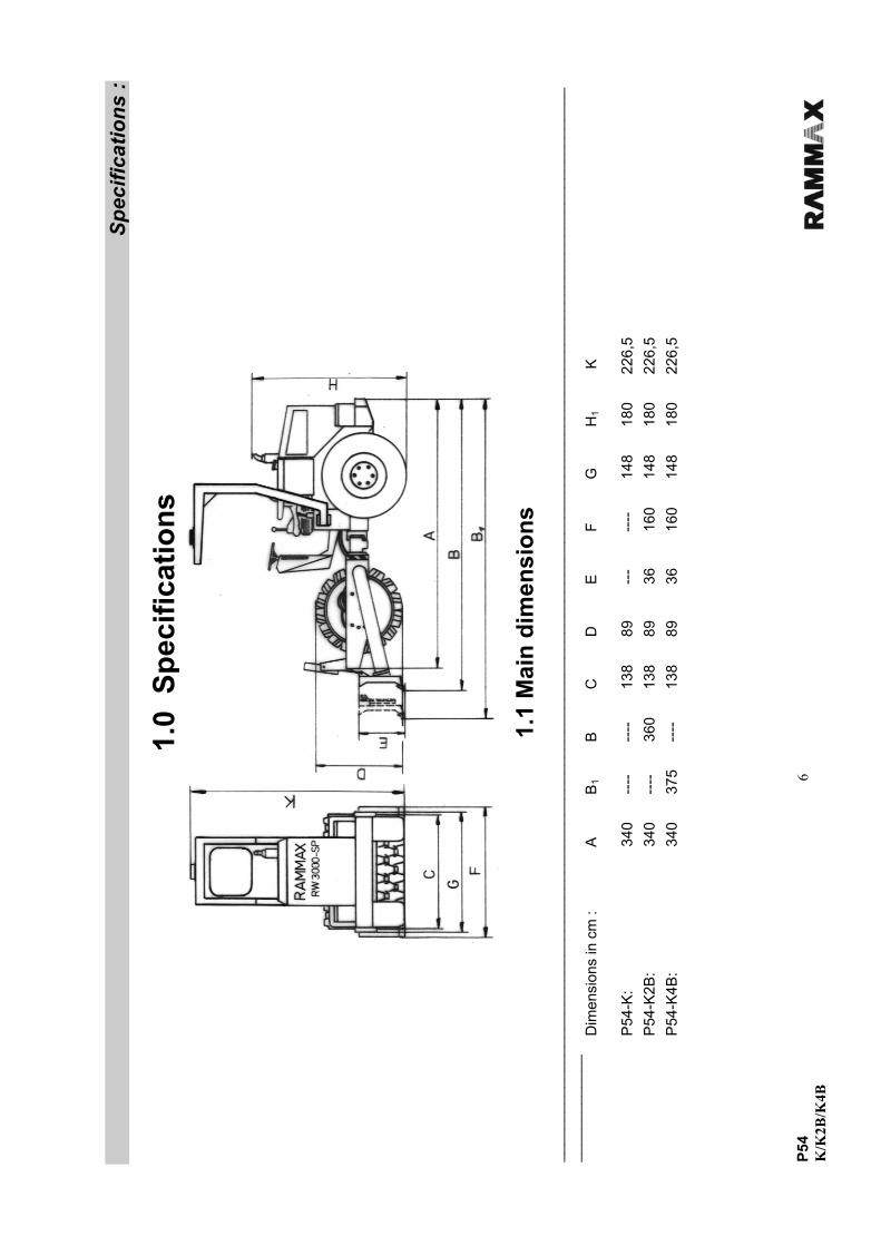
_ D
imen
sion
s in
cm
:
A
B1
B
C
D
E
F G
H
1 K
P
54-K
:
34
0 --
--
----
13
8 89
--
- --
--
148
180
226,
5
P
54-K
2B:
340
----
36
0 13
8 89
36
16
0 14
8 18
0 22
6,5
P54
-K4B
:
34
0 37
5 --
--
138
89
36
160
148
180
226,
5

P54 7 K/K2B/K4B
Specifications : Weights : P54 K P54 K2B P54 K4B
Intrinsic weight : 3100 kg 3300 kg 3400 kg Operational weight : 3340 kg 3560 kg 3640 kg Central axle load : 1500 kg 3100 kg 1650 kg Axle load front/back : 1600/1400 kg 1800/1400 kg 1900/1400 kg Driving characteristics :
Driving speed Forward/reverse : With vibration : 0 - 4 kph 0 - 4 kph 0 - 4 kph Without vibration : 0 - 4 kph 0 - 4 kph 0 - 4 kph Maximum climbing ability :
With vibration : 45 % 45 % 45 % Without vibration : 45 % 45 % 45 % Max. admissible incline 45 % 45 % 45 % Drive system/power unit:
Engine manufacturer : Kubota Kubota Kubota Type : V-1903 V-1903 V-1903 Cooling : water cooling water cooling water cooling No. of cylinders : 4 4 4 Output : 27 kW (38 hp) 27 kW (38 hp) 27 KW (38 hp) Speed : 2930 rpm 2930 rpm 2930 rpm
Battery : 12V 45Ah 12V 45Ah 12V 45Ah Drive mode : hydrostatic hydrostatic hydrostatic Driven axles : front/rear front/rear front/rear Electrical equipment : 12 V 12 V 12 V Brakes :
Service brake : hydrostatic hydrostatic hydrostatic Parking brake : mechanical mechanical mechanical Steering :
Steering mode : articulation articulation articulation Steering actuation : hydrostatic hydrostatic hydrostatic Steering angle : ± 35° ± 35° ± 35° Suspension angle : ± 15° ± 15° ± 15° Vibration system :
Drive mode : hydrostatic hydrostatic hydrostatic Frequency 41 Hz 41 Hz 41 Hz Amplitude 1.7 mm 1.7 mm 1.7 mm Centrifugal force : 87 kN (8500 kp) 87 kN (8500 kp) 87 kN (8500 kp)
P54 8 K/K2B/K4B
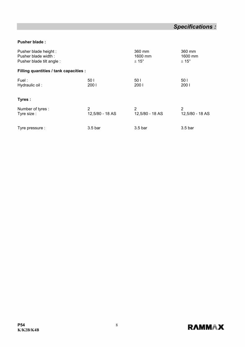
Specifications : Pusher blade : Pusher blade height : 360 mm 360 mm Pusher blade width : 1600 mm 1600 mm Pusher blade tilt angle : ± 15° ± 15° Filling quantities / tank capacities : Fuel : 50 l 50 l 50 l Hydraulic oil : 200 l 200 l 200 l Tyres : Number of tyres : 2 2 2 Tyre size : 12,5/80 - 18 AS 12,5/80 - 18 AS 12,5/80 - 18 AS Tyre pressure : 3.5 bar 3.5 bar 3.5 bar

P54 9 K/K2B/K4B
Specifications :
1.2 Noise and vibration specifications
The noise and vibration specifications listed below in accordance with the EC Machine Directive in the draft (92/68/EEC) were determined under operating conditions typical for the machinery in question with vibration over a specified travel surface. In operational application, deviating values may result depending on the prevailing operating conditions. Noise specification The noise emission specification stipulated in accordance with Annex 1, Section 1.7.4.f of the EC Machine Directive is as follows - Sound pressure level at the operator position : LpA = 91.5 dB(A) - Sound power level : LWA = 106.7 dB(A) These noise emission values were determined in accordance with ISO 6081 for the sound pressure level (LpA) and ISO 3744, DIN 45635, for the sound power level (LWA). Vibration specification The vibration specifications stipulated in accordance with Annex 1, Section 2.2 / 3.6.3. a of the EC Machine Directive are as follows : Subject to modifications
Rammax P54

P54 10 K/K2B/K4B
Description:
2.0 Description Description : Many years of experience, continuous further development and the latest technological innovations in the construction of vibratory trench rollers have culminated in one of the highest-performance machines of the P54 series. All the models of the P54 series are characterized by a high degree of operating convenience, a hard-wearing compact design and outstanding reliability in operation. The RAMMAX P54 is a self-propelling, centre-pivot steered vibratory roller which can be optionally equipped with a sheeps foot facing or a pusher blade. The P54 can also be equipped with a tilt device which permits an even subsoil to be created with the pusher blade even on inclined surfaces. For all machine models of the P54 series, operation of the pusher blade is performed using a single-hand lever. Travel drive, vibration, steering and braking operations are hydraulically powered. The facing and wheels are independently driven and infinitely variable using two control pumps. Travel drive is actuated by two pedals. This drive system permits an outstanding climbing ability (depending on soil conditions 45%) _____________________________________________________________________________________ 2.1 Fields of application :
Vibratory roller P54 is designed especially for levelling and compaction work. The fields of application for this modern vibratory roller include wet conditions, clay soils encountered in canal building, pipelaying work, road substructure work and backfill work. _____________________________________________________________________________________ 2.2 Modifications to the machine :
For reasons of safety, users are prohibited from making their own modifications or conversions to the machine. This machine must only be equipped using original spare parts designed for use with the machine and in compliance with the requirements of the manufacturer. The installation or utilization of special equipment or special parts can impair driving safety. The manufacturer is exonerated of any liability for damage caused as a result of the use of non-original parts or special equipment. _____________________________________________________________________________________

P54
11
K/K
2B/K
4B
3.0
Safe
ty re
gula
tions
12P54 K/K2B/K4B
Safety remarks : 3.1 Use in accordance with the designated purpose :
Vibratory roller P54 is constructed in accordance with the state of the art and with accepted rules of operating safety. However, its use can still give rise to hazardous situations which constitute a danger to life and limb for the operator or for third parties or which can lead to impairment of the machine or damage to other property if • it is used for any other than its designated purpose • it is modified or conversion work carried out by unqualified persons • the safety remarks are not observed • it is not operated or maintained by suitably qualified personnel. The P54 must only be operated when in a technically flawless condition and in accordance with its designated purpose with sufficient awareness of safety aspects and potential hazards and in strict observance of the operating instructions. In particular malfunctions which could detract from the safety of the equipment must be remedied without delay. When operating the roller, adherence to the valid accident prevention regulations and the generally accepted rules of safety, as well as country-specific regulations is assumed. The point "Fields of application" (Section 2.1) outlines the designated purpose for which the P54 is exclusively intended. Any other or further reaching use is deemed to be not in accordance with the designated purpose. The manufacturer/supplier accepts no liability for any damage arising as a result of such incorrect use. All risk arising rests solely with the user. _____________________________________________________________________________________ 3.2 Machine operation : Only suitably qualified and designated persons who have received the appropriate training, and who are over 18 may drive and operate the machine. Fields of responsibility during operation must be clearly defined and adhered to. All persons entrusted with operation, maintenance or repair of the machine must read and adhere to the safety regulations. Where appropriate, this must be confirmed by the user's company by means of a signature by the person or persons concerned. Persons acting under the influence of drugs, medicines or alcohol may not operate, maintain or repair the machine. Maintenance and repair call for special knowledge and may only be performed by suitably trained and qualified personnel. _____________________________________________________________________________________ 3.3 Safety remarks in the operating and maintenance instructions:
Danger This warning sign is an indication of possible danger of personal injury.
Note : This warning sign is an indication of possible impairment to the machine or parts of the equipment. Remark : These parts of the instructions provide technical information intended
to ensure optimum economy and efficient use of the machine.
13P54 K/K2B/K4B
Safety remarks : 3.4 Safety signs applied to the machine : Keep all safety plates and labels in good legible order and ensure their observance.
Damaged and illegible safety plates and labels must be renewed without delay.
Spares of all plates and labels are available, see the spare parts list. 3.5 Loading the machine for transport: - Only use stable loading ramps with sufficient load-bearing capacity. The ramp incline must not be any steeper than the specified climbing ability (see Specifications) of the machine. - Safeguard the machine against tilting or slipping. - Safeguard the machine on transport vehicles against rolling, slipping and tipping over. - When suspended, the machine may only be permitted a minimal rocking motion. The following situations represent a danger to life and limb:
• Walking or standing under suspended loads. • Remaining within the driving area of the machine while it is being guided into position and loaded. 3.6 Towing the machine : Always use a tow rod for all towing operations !
The maximum towing speed of 1 kph must not be exceeded. Never tow the machine further than 200 mm.
When mechanically releasing the disk brake, safeguard the machine against unintentional rolling away. 3.7 Checking the rollover bar (ROPS) The machine frame must not be damaged, distorted or demonstrate any cracks in the area of the ROPS roof fixture.
Neither must the ROPS roof itself demonstrate any hairline cracks, rusting or open breakages.
Marked vibrations or rattling of the ROPS roof is an indication of inadequate fixture. All screw connections must be tightened in accordance with the stipulated values (note tightening torque levels). All fastening screws must be free of damage, bends or deformations.
No supplementary parts may be welded or screwed on without the agreement of the manufacturer, as this can impair the strength and represent a safety hazard for the machine operator. The drilling of holes or flame cutting of recesses are not admissible in the area of the ROPS roof, as these can also impair strength.
14P54 K/K2B/K4B
Safety remarks : 3.8 Starting the machine : 3.8.1 Before starting - Familiarize yourself with the equipment, the operating and control elements and the functional characteristics of the machine in the respective field of application.
- Use personal safety gear (safety helmet, safety shoes, ear protection etc.). Before starting, check whether
• there are persons or impediments located next to or under the machine • the machine is free of oily and flammable materials • all handles, steps and platforms are free of grease, oil, fuels, dirt, snow and ice • the machine demonstrates any obvious defects • all protective gear is firmly in place • brakes, steering and operating elements are working • the driver's seat is correctly set - Never start the machine if any instruments, pilot lamps or control organs are defective. - Do not tie any loose objects onto the machine. - When climbing onto the machine, only use the provided stairs, steps and handles.
Danger - In the case of machines with ROPS roof (rollover bar), safety belts must always be worn ! 3.8.2 Starting : Only ever start up and operate the machine from the driver's seat.
For starting, all operating levers must be in the "Neutral position"
After starting, check all display and operating elements. 3.8.3 Jump starting with jump leads :
Note : The machine is equipped with a 12-Volt system! Connect the plus to the plus terminal and the minus to the minus terminal (earth cable). Connect the earth cable last and disconnect first! Incorrect connection will result in serious damage to the machine's electrical system.
15P54 K/K2B/K4B
Safety remarks : 3.9 Driving the machine :
3.9.1 Persons in the hazard area
Each time before starting work, also after interruptions, check whether there are persons or obstacles positioned in the hazard area, particularly when reversing. If required, give a warning signal. Stop work immediately if persons fail to leave the hazard area despite warning. When the engine is running, never enter the articulation range of the machine. Danger of crushing! 3.9.2 Driving :
- In emergency situations and in case of danger, stop the machine immediately. Only resume operation when the danger which caused the stop has been remedied. - The machine may not be used to transport persons. - In case of unusual noises and generation of smoke, ascertain the cause and have the problem remedied. - The machine may only be operated from the driver's seat. - Do not adjust the driver's seat while driving - During driving operation, do not climb onto or off the machine. If the machine has touched a live electrical cable : - Do not leave the driver's seat - Warn bystanders against approaching or touching the machine - If possible, travel out of the danger area - Arrange for the current to be disconnected 3.9.3 Negotiating uphill and downhill slopes :
- Do not drive up or down slopes steeper than the maximum climbing ability of the machine. - On slopes, always drive directly upwards or downwards and proceed with caution. Before approaching, select a lower gear. - Damp and loose substrates substantially reduce the machine's grip on sloping surfaces and inclines. Increased risk of accidents! 3.9.4 Driving in traffic :
- Adjust your speed to the work conditions. - Always give way to loaded transport vehicles. - Keep your distance from edges and embankments.
16P54 K/K2B/K4B
Safety remarks : 3.9.5 Checking the effects of vibration :
During compaction work with vibration, check the effect on adjacent buildings and buried pipelines (gas, water, sewage, electrical). If necessary, compaction work may have to be discontinued. Never use vibration on hard substrates (concrete or frozen earth), as this will damage the bearings! 3.9.6 Parking the machine : Wherever possible, park the machine on a firm, even surface. Before leaving the machine :
• Straighten up the articulated joint in order to simplify mounting and descending • Switch off the engine and pull out the ignition key. • Move the shift lever to neutral.
Parked machines which could represent an obstruction must be safeguarded by clearly identifiable measures. Never jump off the machine, but use the provided handles, steps and stairs. 3.9.7 Parking on slopes and inclines :
Safeguard the machine against rolling away. To do this use metal chocks in front of and behind the facings.
3.9.8 Starting in enclosed areas :
Exhaust fumes are lethal ! When starting the engine in enclosed areas, ensure that sufficient ventilation is provided. 3.10 Refuelling :
• Never breathe in fuel fumes. • Only refuel when the engine is switched off.
• Never refuel in enclosed areas. • No naked flames, no smoking.
• Do not spill fuel, mop up any splashes of fuel, do not allow to seep into the ground.
• Mixtures of diesel fuel and petrol (never Super petrol) should only be combined in the tank itself. First fill in the necessary quantity of petrol, then top up with diesel fuel. Petrol diesel fuel mixes are equally inflammable as petrol.
17P54 K/K2B/K4B
Safety remarks :
3.11 Maintenance work :
- Maintenance work may only be performed by suitably qualified and trained personnel.
- Keep unauthorized persons away from the machine.
- Never carry out maintenance work on a driving machine or with the engine running.
- Park the machine on a firm, even surface.
- Take the key out of the ignition.
- Safeguard the articulated joint with the transport safeguard. 3.11.1 Work on the hydraulic line :
Before performing any work on hydraulic systems, they must be depressurized. Hydraulic oil emerging under pressure can penetrate the skin and cause serious injury. In case of injury due to oil emerging at high pressure, immediately consult a doctor as serious infections can result.
When performing setting work at the hydraulic system, do not tread in front of or behind the facings.
Do not adjust the pressure relief valve.
Drain off the hydraulic oil at operating temperature – danger of scalding!
Collect up emerging hydraulic oil and dispose of in an environmentally responsible manner.
Never attempt to start the engine when the hydraulic oil has been drained.
After the completion of all work (with the system still depressurized!), check the seal of all connections and screw joints. 3.11.2 Exchanging hydraulic hose lines :
Hose lines must never be swapped or exchanged.
Subject hydraulic hose lines to regular visual inspections.
The immediate exchange of hydraulic hose lines is essential in the following cases :
• Damage of the outer ply through to the inlay (e.g. abrasion, cuts) • Brittleness of the outer ply (crack formation in the hose material). • Deformation in pressureless or pressurized condition which does not correspond with the original shape of the hydraulic hose line. • Deformation on bending, e.g. crushing points, kinks, separation of plies, formation of blisters. • Leaks. • Incorrectly executed installation. • Migration of the hydraulic hose from the fitting. • Corrosion of the fitting which impairs functional characteristics and strength. • Damage or deformation of the fitting which impairs functional characteristics, strength or the hose to hose connection
Only original RAMMAX spare hydraulic hose lines offer the security of using the correct hose type (pressure stage) in the right situation.

18P54 K/K2B/K4B
Safety remarks : 3.11.3 Work at the engine: Drain off the engine oil at operating temperature – Danger of scalding!
Wipe away any spilt oil, collect emerging oil and dispose of in an environmentally responsible manner.
Keep used filters and other oil-soiled materials in a separate, specially marked container and dispose of in an environmentally responsible manner. 3.11.4 Work on the electrical system : • Before performing work on the electrical system, disconnect the battery and cover with isolating material. • Do not use fuses with a higher amperage or repair fuses. Fire hazard! 3.11.5 Work on the battery : • When carrying out work at the battery, never smoke or expose to a naked flame. • Do not allow acid to contact hands or clothing. In case of injury due to acid spillage, rinse with clear water and consult a doctor. • Never place any tools on the battery. • Dispose of old batteries in compliance with regulations. 3.11.6 Work at the fuel system : No naked flames, no smoking, do not spill fuel. Collect emerging fuel, do not allow to seep into the ground and dispose of in an environmentally friendly manner. 3.11.7 Cleaning work : • Never carry out cleaning work with the engine running. • Never use petrol or other easily flammable materials for cleaning. • When cleaning using a steam jet cleaning device, cover all electrical parts and the insulating material or do not expose to direct water or steam jet. • Do not hold the cleaning jet in the sound absorber. 3.11.8 After completing maintenance work : - All protective devices must be replaced after cleaning and maintenance work. - Carry out performance checks. 3.12 Repairs : If the machine is defective, hang a warning sign on the machine.
Repairs may only be performed by qualified and specially commissioned personnel. Exhaust gas is lethal! When starting the engine in enclosed areas, ensure that sufficient ventilation is provided!
19P54 K/K2B/K4B
Display and operating elements :
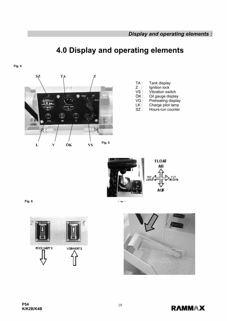
4.0 Display and operating elements
TA : Tank display Z : Ignition lock VS : Vibration switch ÖK : Oil gauge display VG : Preheating display LK : Charge pilot lamp SZ : Hours-run counter
Fig. 4
Fig. 5
Fig. 6
Fig. 7
L V ÖK VS
SZ TA Z
20P54 K/K2B/K4B
Display and operating elements :
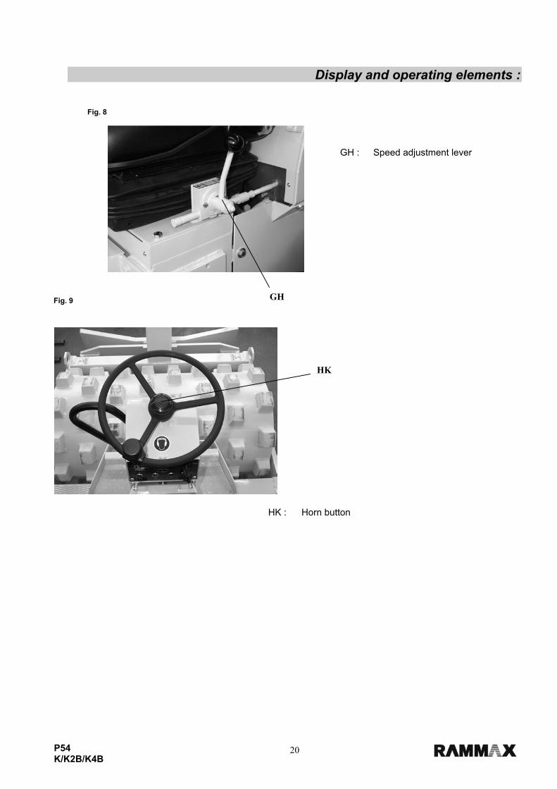
GH : Speed adjustment lever
HK : Horn button
Fig. 8
Fig. 9 GH
HK
21P54 K/K2B/K4B
Description of the display and operating elements :
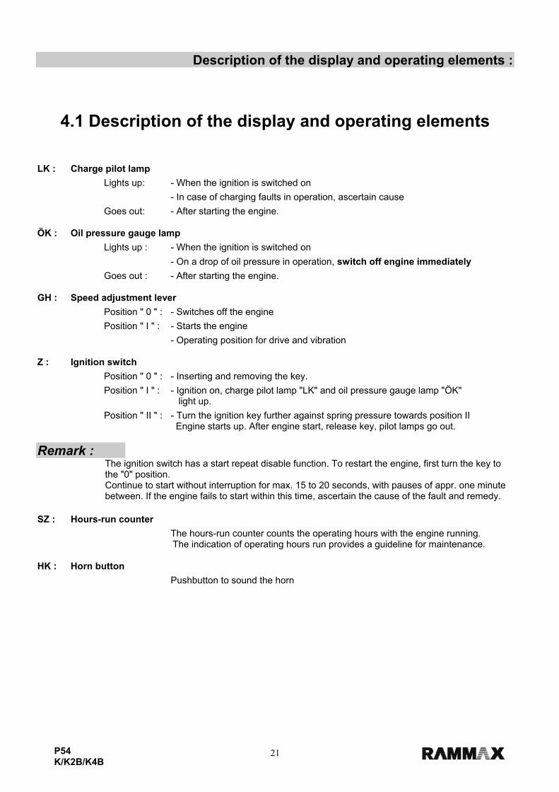
4.1 Description of the display and operating elements LK : Charge pilot lamp
Lights up: - When the ignition is switched on
- In case of charging faults in operation, ascertain cause
Goes out: - After starting the engine. ÖK : Oil pressure gauge lamp
Lights up : - When the ignition is switched on
- On a drop of oil pressure in operation, switch off engine immediately
Goes out : - After starting the engine. GH : Speed adjustment lever
Position " 0 " : - Switches off the engine
Position " I " : - Starts the engine
- Operating position for drive and vibration Z : Ignition switch
Position " 0 " : - Inserting and removing the key.
Position " I " : - Ignition on, charge pilot lamp "LK" and oil pressure gauge lamp "ÖK" light up.
Position " II " : - Turn the ignition key further against spring pressure towards position II Engine starts up. After engine start, release key, pilot lamps go out. Remark :
The ignition switch has a start repeat disable function. To restart the engine, first turn the key to the "0" position. Continue to start without interruption for max. 15 to 20 seconds, with pauses of appr. one minute between. If the engine fails to start within this time, ascertain the cause of the fault and remedy.
SZ : Hours-run counter
The hours-run counter counts the operating hours with the engine running. The indication of operating hours run provides a guideline for maintenance.
HK : Horn button
Pushbutton to sound the horn
22P54 K/K2B/K4B
Operation :
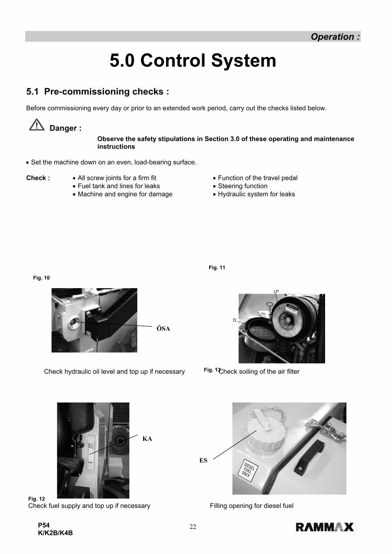
5.0 Control System 5.1 Pre-commissioning checks : Before commissioning every day or prior to an extended work period, carry out the checks listed below.
Danger :
Observe the safety stipulations in Section 3.0 of these operating and maintenance instructions
• Set the machine down on an even, load-bearing surface. Check : • All screw joints for a firm fit • Function of the travel pedal • Fuel tank and lines for leaks • Steering function • Machine and engine for damage • Hydraulic system for leaks
Fig. 10 Check hydraulic oil level and top up if necessary Check soiling of the air filter
Fig. 11
Fig. 13
Fig. 12 Check fuel supply and top up if necessary Filling opening for diesel fuel
KA
ES
ÖSA
23P54 K/K2B/K4B
Operation :
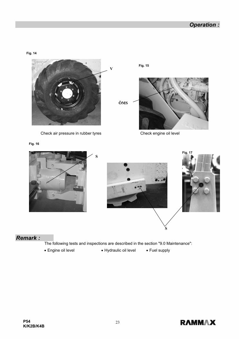
Remark : The following tests and inspections are described in the section "9.0 Maintenance":
• Engine oil level • Hydraulic oil level • Fuel supply
Fig. 14 Check air pressure in rubber tyres Check engine oil level
Fig. 15
Fig. 17
Fig. 16
V
ÖMS
S
S
24P54 K/K2B/K4B
Operation : 5.2 Commissioning
Note :
• Desist from any method of operation which could pose a safety hazard or impair the static stability of the machine. • Never travel on sloping surfaces transversely, but always directly upwards or downwards. • The machine may only be started from the driver's seat • When leaving the driver's seat, the machine must always be safeguarded against unintentional rolling away or unauthorized use.
Danger : Before driving, check whether persons are located in the driving area.
It is prohibited for persons to remain in the articulation area of the roller when the engine is running.
Damp and loose substrates substantially reduce the machine's grip on sloping surface and inclines.
When driving up slopes and inclines, the speed must be adjusted in line with the terrain.
The properties of the soil and the effects of weather can impair the climbing ability of the machine.
Never attempt to negotiate slopes which are steeper than the machine's climbing ability.
Always give way to loaded transport vehicles. _______________________________________________________________________________________________
5.3 Start procedure :
Note :
Should you not yet have familiarized yourself with the operating and display elements of this machine, it is essential for you to read through the preceding section "Operating and display elements" and to become familiar with its contents. All display and operating elements are described here in detail. When operating this machine, the safety remarks and the respective safety regulations described in section 3.0 must be observed without fail.
______________________________________________________________________________________
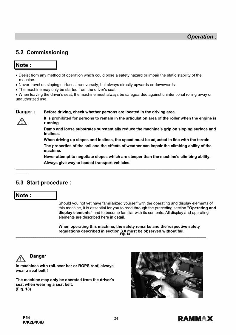
Danger In machines with roll-over bar or ROPS roof, always wear a seat belt ! The machine may only be operated from the driver's seat when wearing a seat belt. (Fig. 18)
Fig. 18
25P54 K/K2B/K4B
Operation : 5.4 Starting the engine : 1. Move the gas lever to the "Start" position (Fig. 8, Page 20). 2. Move the control lever for the pusher blade to the neutral position (Page 19, Fig. 5). 3. Turn the ignition switch "Z" to the "I" position (Page 19, Fig. 4). 4. Turn the vibration switch "VS" to the central position (Page 19, Fig. 4) 5. The pedals must not be actuated during engine start-up. (Page 19, Fig. 7) The oil gauge pilot lamp "ÖK" and charge pilot lamp "LK" light up When starting the engine, the start instructions of the engine manufacturer must be observed. • Turn the ignition switch to the "II" position. The engine starts.
• Immediately let go of the ignition key once the engine is running.
Note : The starter must never be actuated while the engine is already running! This could lead to serious damage to the starter and the starter ring gear
Remark : Before starting work, allow the engine to warm up briefly in idle operation. ______________________________________________________________________________________ 5.5 Starting with jump leads :
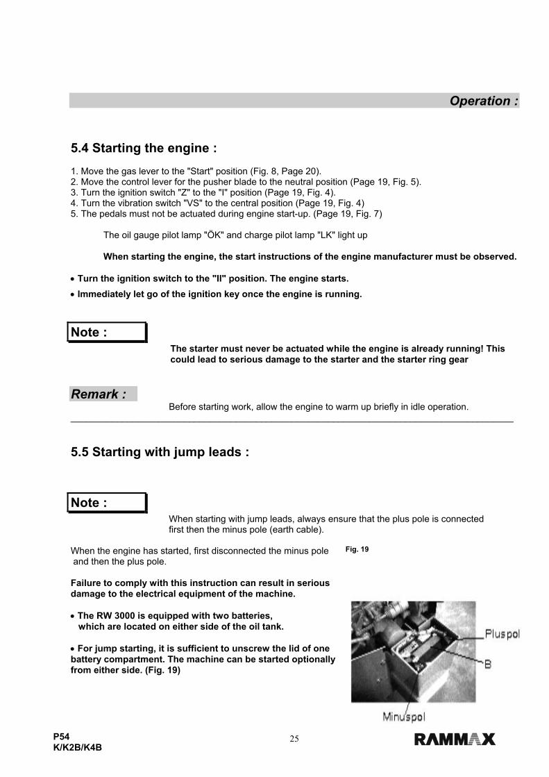
Note : When starting with jump leads, always ensure that the plus pole is connected
first then the minus pole (earth cable). When the engine has started, first disconnected the minus pole and then the plus pole. Failure to comply with this instruction can result in serious damage to the electrical equipment of the machine. • The RW 3000 is equipped with two batteries, which are located on either side of the oil tank. • For jump starting, it is sufficient to unscrew the lid of one battery compartment. The machine can be started optionally from either side. (Fig. 19)
Fig. 19
26P54 K/K2B/K4B
Operation : 5.6 Driving operation : The machine is set in motion by actuation of the drive pedals.
When actuating the left-hand drive pedal, the machine travels in reverse, when actuating the right-hand drive pedal, the machine travels forwards.
The speed can be steplessly adjusted depending on pedal deflection. (Fig. 6, 7) _______________________________________________________________________________________________ 5.7 Vibration : Machine vibration is switched on using the rocker switch "VS". (Fig. 4, Page 20) Remark : • Machines which are equipped with a pusher blade can only perform
compaction work with the blade in the raised position
• Simultaneous levelling and compaction is not possible.
Important : • All compaction work may only be performed at maximum engine speed!
Danger : During compaction work near buildings or structures, check the effects
on neighbouring structures and if necessary discontinue the work. ______________________________________________________________________________________ 5.8 Actuation of the pusher blade : The pusher blade is actuated using control lever (Fig. 5, Page 19). 1. Control lever back : Lift pusher blade 2. Control lever forward : Lower pusher blade 3. Control lever left : Pusher blade turns to the left (tilt device) 4. Control lever right : Pusher blade turns to the right (tilt device)
5. Control lever to position "FLOAT" : Pusher blade float position (during reverse travel to smooth the terrain) Remark :
The pusher blade must be rested on the floor every time before switching off the engine.
Danger : Persons may not be transported on the pusher blade
Movement of other vehicles with the aid of the pusher blade is prohibited.
27P54 K/K2B/K4B
Operation : 5.9 Switching off the machine 1. Move the gas lever to the "Stop" position. (Fig. 8, Page 20) 2. Before switching off, allow the engine to run for a brief period at idle speed to equalize
the temperature. 3. Switch the ignition key to the "0" position. (Engine - Stop) (Fig. 4, Page 19)
Note :
Before switching off the engine, align the machine straight in order to permit simpler mounting and descent. After switching off the machine, pull out the ignition key. The cover over the instruments must be closed in order to protect the machine from damage or vandalism.
The pusher blade must be lowered to the ground before switching off the engine.
When switching off the machine on slopes, always safeguard using chocks. ______________________________________________________________________________________ 6.0 Setting the driver's seat :
Danger : It is strictly prohibited to set the driver's seat while driving. Danger of accidents!
In the case of machines with rollover bar or ROPS roof, always wear your seat belt before starting the machine.
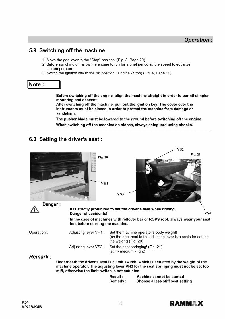
Operation : Adjusting lever VH1 : Set the machine operator's body weight!
(on the right next to the adjusting lever is a scale for setting the weight) (Fig. 20)
Adjusting lever VS2 : Set the seat springing! (Fig. 21) (stiff - medium - light) Remark :
Underneath the driver's seat is a limit switch, which is actuated by the weight of the machine operator. The adjusting lever VH2 for the seat springing must not be set too stiff, otherwise the limit switch is not actuated.
Result : Machine cannot be started Remedy : Choose a less stiff seat setting
Fig. 21Fig. 20
VH1
VS2
VS3
VS4
28P54 K/K2B/K4B
Operation : Adjusting lever VS3 : Setting the tilt of the backrest by turning the adjusting knob.
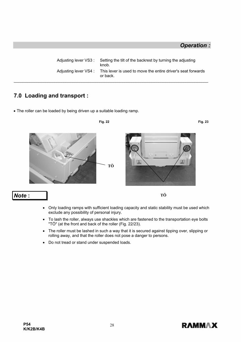
Adjusting lever VS4 : This lever is used to move the entire driver's seat forwards or back. ______________________________________________________________________________________ 7.0 Loading and transport : • The roller can be loaded by being driven up a suitable loading ramp.
Note :
• Only loading ramps with sufficient loading capacity and static stability must be used which exclude any possibility of personal injury.
• To lash the roller, always use shackles which are fastened to the transportation eye bolts "TÖ" (at the front and back of the roller (Fig. 22/23).
• The roller must be lashed in such a way that it is secured against tipping over, slipping or rolling away, and that the roller does not pose a danger to persons.
• Do not tread or stand under suspended loads.
Fig. 22 Fig. 23
TÖ
TÖ
29P54 K/K2B/K4B
Operation :
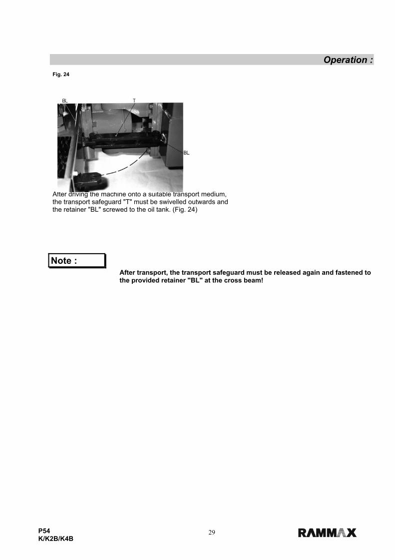
Note : After transport, the transport safeguard must be released again and fastened to the provided retainer "BL" at the cross beam!
Fig. 24 After driving the machine onto a suitable transport medium, the transport safeguard "T" must be swivelled outwards and the retainer "BL" screwed to the oil tank. (Fig. 24)

30P54 K/K2B/K4B
Maintenance :
8.0 Maintenance 8.1 General remarks on maintenance and maintenance work : Steps must be taken to ensure that all safety regulations are adhered to in the execution of maintenance work! Careful machine maintenance guarantees far greater functional reliability and increases the life of all important components. The necessary input is minimal in relation to the faults and problems which can occur as a result of failure to perform maintenance work. • The engine and machine must be thoroughly cleaned before performing any maintenance work. • Maintenance work may only be performed when the engine is at a standstill. • When working with the hydraulic system, this must first be depressurized. • Before working on the electrical system, detach the battery, cover it and protect with insulating material. • Check the electrical equipment of the machine at regular intervals. Defects such as loose connections or melted cables must be remedied immediately and replaced by new ones. • Only carry out maintenance and repair work when the machine is positioned on an even surface capable of bearing loads and safeguarded against rolling away. • Adhere to the prescribed maintenance and inspection procedures in the operating instructions, including instructions in the exchange of parts. This work may only be performed by specialized personnel. • Oil and fuels must not be permitted to seep into the ground or sewage system during maintenance work. These must be collected using suitable means and disposed of in an environmentally responsible manner. Remarks on the hydraulic system: Avoid dirt or other contaminants entering the hydraulic system. Even the smallest dirt particles in the hydraulic pipework can lead to tremendous impairment to hydraulic units and so to costly repairs. • Should it be discovered during the daily check of the hydraulic oil level that the oil level is sinking, the complete hydraulic pipework must be checked immediately for leaks.
• Leaks must be repaired immediately. If necessary, inform the responsible after-sales service.
• If possible fill the hydraulic system with filling aggregate.
• Clean screw joints, the filling cap and its surroundings before removal to prevent the ingress of dirt particles.
• Do not leave the tank cap open unnecessarily to prevent foreign bodies entering the system. 8.2 Running in regulations : Maintenance after 25 hours of operation: • Check all screw connections and tighten if necessary. • Check hydraulic hoses and the complete hydraulic oil system for leaks. • Exchange the fuel filter. (Fig. 18, Section 10.7)) • Engine : See maintenance instructions Kubota D-1703!
31P54 K/K2B/K4B
Maintenance :
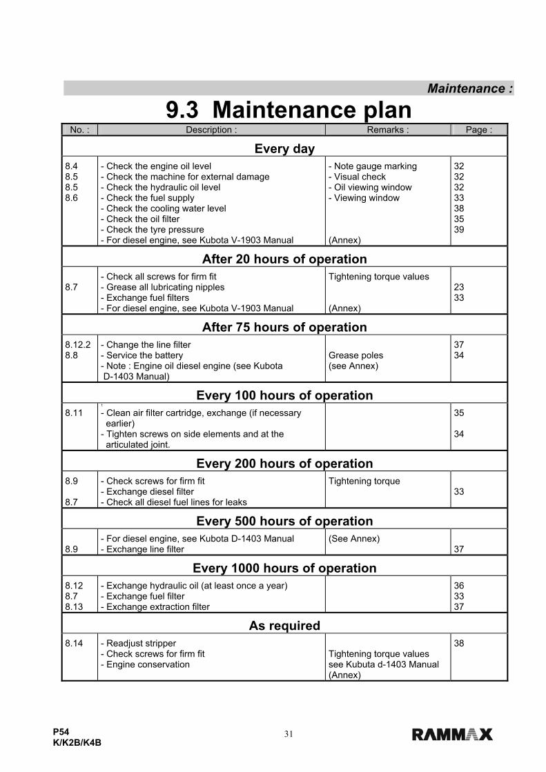
9.3 Maintenance plan No. : Description : Remarks : Page :
Every day
8.4 8.5 8.5 8.6
- Check the engine oil level - Check the machine for external damage - Check the hydraulic oil level - Check the fuel supply - Check the cooling water level - Check the oil filter - Check the tyre pressure - For diesel engine, see Kubota V-1903 Manual
- Note gauge marking - Visual check - Oil viewing window - Viewing window (Annex)
32 32 32 33 38 35 39
After 20 hours of operation
8.7
- Check all screws for firm fit - Grease all lubricating nipples - Exchange fuel filters - For diesel engine, see Kubota V-1903 Manual
Tightening torque values (Annex)
23 33
After 75 hours of operation
8.12.2 8.8
- Change the line filter - Service the battery - Note : Engine oil diesel engine (see Kubota D-1403 Manual)
Grease poles (see Annex)
37 34
Every 100 hours of operation
8.11 1
- Clean air filter cartridge, exchange (if necessary earlier) - Tighten screws on side elements and at the articulated joint.
35 34
Every 200 hours of operation
8.9 8.7
- Check screws for firm fit - Exchange diesel filter - Check all diesel fuel lines for leaks
Tightening torque
33
Every 500 hours of operation
8.9
- For diesel engine, see Kubota D-1403 Manual - Exchange line filter
(See Annex)
37
Every 1000 hours of operation
8.12 8.7 8.13
- Exchange hydraulic oil (at least once a year) - Exchange fuel filter - Exchange extraction filter
36 33 37
As required
8.14
- Readjust stripper - Check screws for firm fit - Engine conservation
Tightening torque values see Kubuta d-1403 Manual (Annex)
38
32P54 K/K2B/K4B
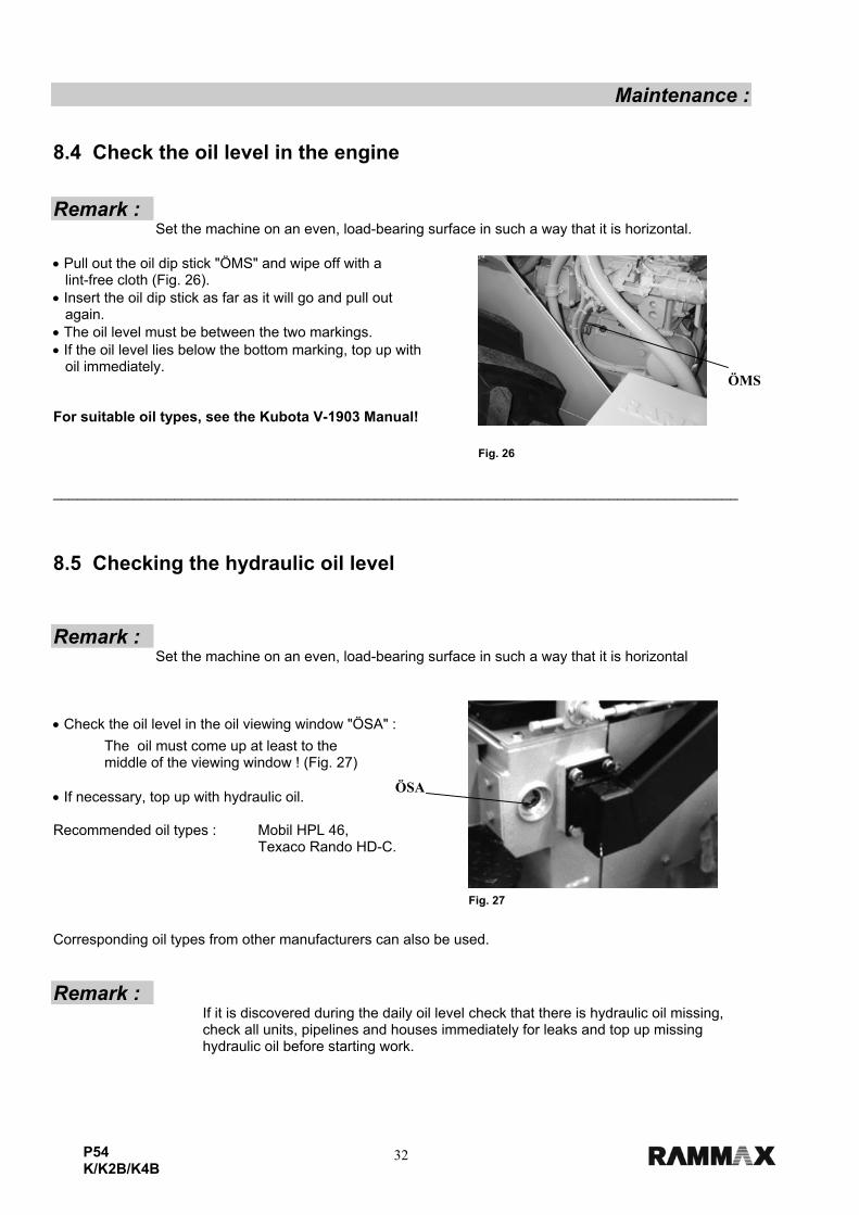
Maintenance : 8.4 Check the oil level in the engine Remark : Set the machine on an even, load-bearing surface in such a way that it is horizontal. • Pull out the oil dip stick "ÖMS" and wipe off with a lint-free cloth (Fig. 26). • Insert the oil dip stick as far as it will go and pull out again. • The oil level must be between the two markings. • If the oil level lies below the bottom marking, top up with oil immediately. For suitable oil types, see the Kubota V-1903 Manual!
_____________________________________________________________________________________ 8.5 Checking the hydraulic oil level Remark : Set the machine on an even, load-bearing surface in such a way that it is horizontal • Check the oil level in the oil viewing window "ÖSA" :
The oil must come up at least to the middle of the viewing window ! (Fig. 27) • If necessary, top up with hydraulic oil. Recommended oil types : Mobil HPL 46, Texaco Rando HD-C.
Corresponding oil types from other manufacturers can also be used. Remark :
If it is discovered during the daily oil level check that there is hydraulic oil missing, check all units, pipelines and houses immediately for leaks and top up missing hydraulic oil before starting work.
Fig. 26
Fig. 27
ÖMS
ÖSA
33P54 K/K2B/K4B
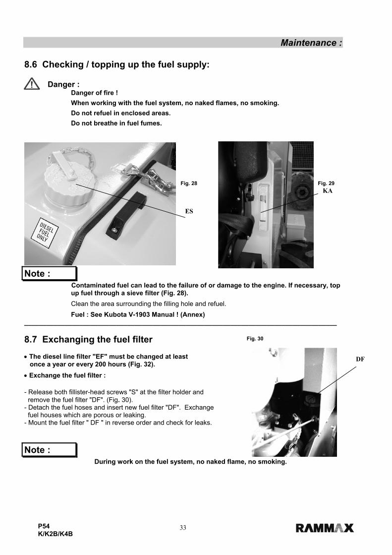
Maintenance : 8.6 Checking / topping up the fuel supply:
Danger : Danger of fire !
When working with the fuel system, no naked flames, no smoking.
Do not refuel in enclosed areas.
Do not breathe in fuel fumes.
Note : Contaminated fuel can lead to the failure of or damage to the engine. If necessary, top up fuel through a sieve filter (Fig. 28).
Clean the area surrounding the filling hole and refuel.
Fuel : See Kubota V-1903 Manual ! (Annex) _____________________________________________________________________________________ 8.7 Exchanging the fuel filter • The diesel line filter "EF" must be changed at least once a year or every 200 hours (Fig. 32).
• Exchange the fuel filter :
- Release both fillister-head screws "S" at the filter holder and remove the fuel filter "DF". (Fig. 30). - Detach the fuel hoses and insert new fuel filter "DF". Exchange fuel houses which are porous or leaking. - Mount the fuel filter " DF " in reverse order and check for leaks.
Note : During work on the fuel system, no naked flame, no smoking.
Fig. 29Fig. 28
Fig. 30
ES
KA
DF
34P54 K/K2B/K4B
Maintenance : - The fuel system is self-venting.
Note : Collect any emerging fuel and dispose of in an environmentally responsible manner using a fuel filter !
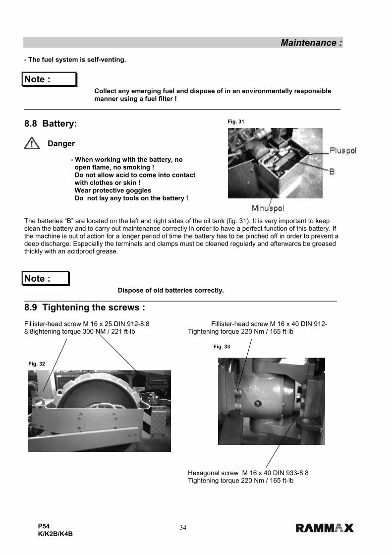
______________________________________________________________________________________ 8.8 Battery:
Danger - When working with the battery, no open flame, no smoking ! Do not allow acid to come into contact
with clothes or skin ! Wear protective goggles Do not lay any tools on the battery ! The batteries “B” are located on the left and right sides of the oil tank (fig. 31). It is very important to keep clean the battery and to carry out maintenance correctly in order to have a perfect function of this battery. If the machine is out of action for a longer period of time the battery has to be pinched off in order to prevent a deep discharge. Especially the terminals and clamps must be cleaned regularly and afterwards be greased thickly with an acidproof grease.
Note : Dispose of old batteries correctly. _____________________________________________________________________________________ 8.9 Tightening the screws : Fillister-head screw M 16 x 25 DIN 912-8.8 Fillister-head screw M 16 x 40 DIN 912-8.8ightening torque 300 NM / 221 ft-lb Tightening torque 220 Nm / 165 ft-lb
Hexagonal screw M 16 x 40 DIN 933-8.8 Tightening torque 220 Nm / 165 ft-lb
Fig. 31
Fig. 33
Fig. 32

35P54 K/K2B/K4B
Maintenance : 8.10 Cleaning/checking/exchanging/ the air filter Exchange the air filter cartridge : • Release the sealing cap " D " from the air filter housing and remove air filter cartridge "LP". • After inserting the cleaned or new filter cartridge, mount the sealing cap "D". (Fig. 34)
Note:
Never use petrol or hot fluid to clean the filter cartridge !!!
After cleaning, the filter cartridge must be examined using a lamp for damage.
Filter cartridges which are damaged at the seal or at the cartridge itself must be exchanged without fail.
The filter cartridge of the air filter must be exchanged after being cleaned three times or after a year at the latest.
If the filter cartridge is contaminated with sooty deposits, cleaning is not possible. Use a new cartridge.
Each completed cleaning process of the filter cartridge must be documented on the lid of the cartridge.
Insufficient cleaning and handling of the filter cartridge can lead to serious damage to the engine!!! Dry cleaning :
Danger Danger to the eyes! Wear protective clothing (protective goggles, gloves)
• Blow through the filter cartridge using dry compressed air (max. 5 bar) from the inside to the outside. Wet cleaning : Clean the filter cartridge by waving backwards and forwards in lukewarm water using a standard commercially available mild detergent. Then rinse well in cold water, spin and leave to dry well. _____________________________________________________________________________________
Fig.34
36P54 K/K2B/K4B
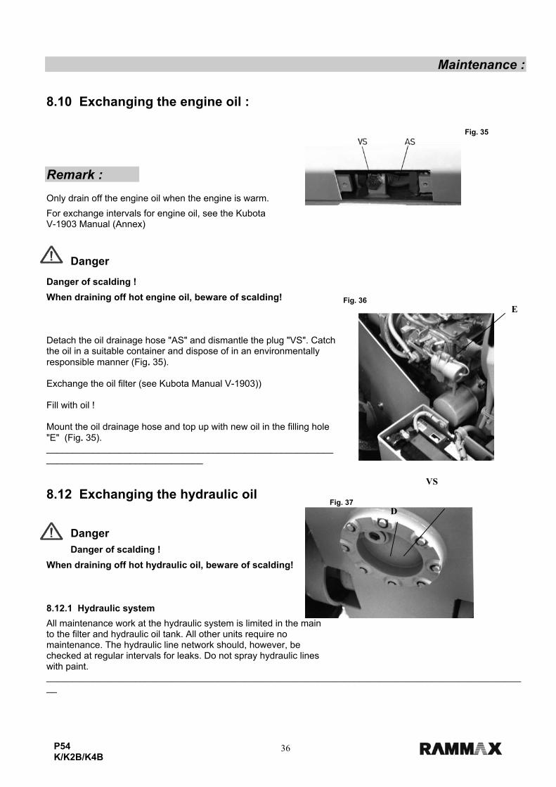
Maintenance : 8.10 Exchanging the engine oil :
Remark : Only drain off the engine oil when the engine is warm.
For exchange intervals for engine oil, see the Kubota V-1903 Manual (Annex)
Danger
Danger of scalding !
When draining off hot engine oil, beware of scalding! Detach the oil drainage hose "AS" and dismantle the plug "VS". Catch the oil in a suitable container and dispose of in an environmentally responsible manner (Fig. 35). Exchange the oil filter (see Kubota Manual V-1903)) Fill with oil ! Mount the oil drainage hose and top up with new oil in the filling hole "E" (Fig. 35). _____________________________________________________________________________________ 8.12 Exchanging the hydraulic oil
Danger
Danger of scalding !
When draining off hot hydraulic oil, beware of scalding! 8.12.1 Hydraulic system
All maintenance work at the hydraulic system is limited in the main to the filter and hydraulic oil tank. All other units require no maintenance. The hydraulic line network should, however, be checked at regular intervals for leaks. Do not spray hydraulic lines with paint. _____________________________________________________________________________________________
Fig. 35
Fig. 36
Fig. 37
D
VS
E
37P54 K/K2B/K4B
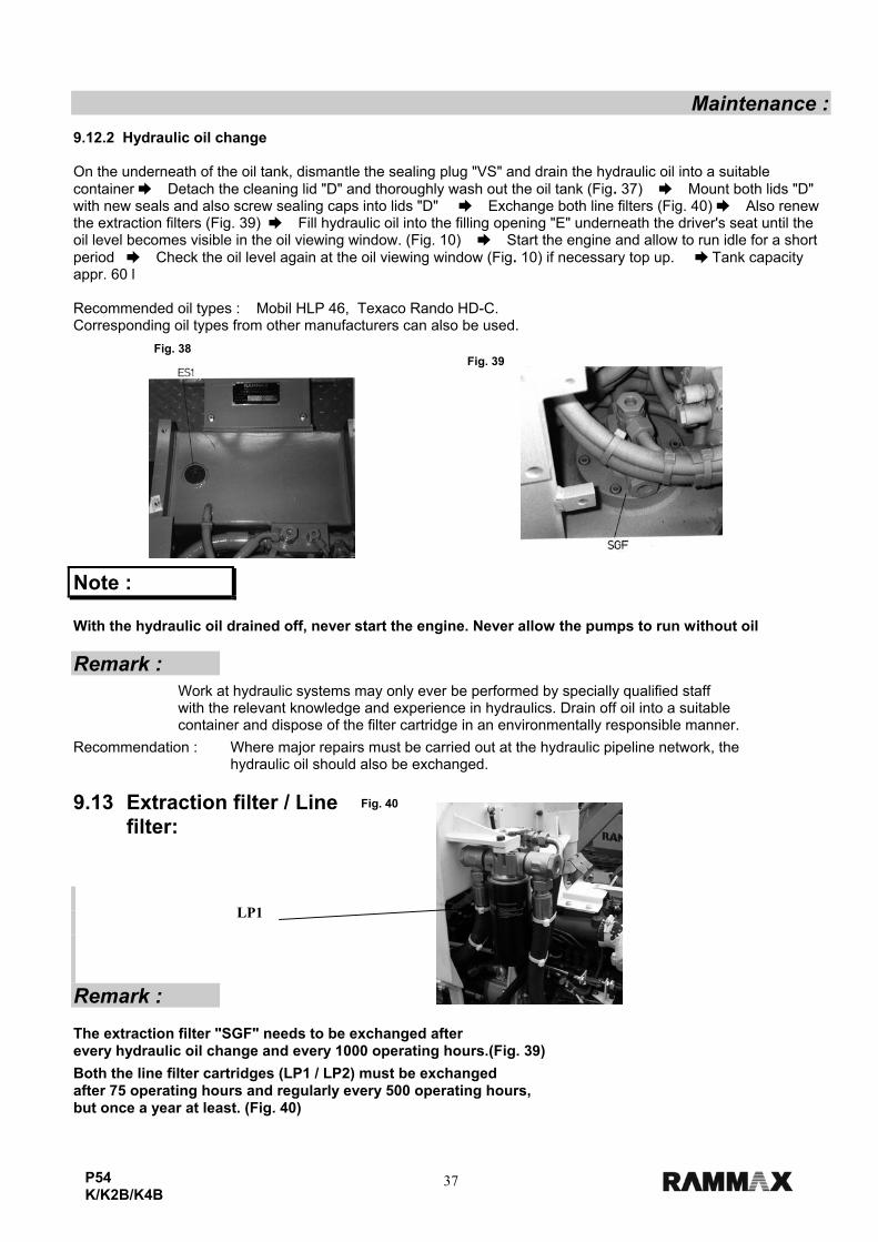
Maintenance : 9.12.2 Hydraulic oil change On the underneath of the oil tank, dismantle the sealing plug "VS" and drain the hydraulic oil into a suitable container Detach the cleaning lid "D" and thoroughly wash out the oil tank (Fig. 37) Mount both lids "D" with new seals and also screw sealing caps into lids "D" Exchange both line filters (Fig. 40) Also renew the extraction filters (Fig. 39) Fill hydraulic oil into the filling opening "E" underneath the driver's seat until the oil level becomes visible in the oil viewing window. (Fig. 10) Start the engine and allow to run idle for a short period Check the oil level again at the oil viewing window (Fig. 10) if necessary top up. Tank capacity appr. 60 l Recommended oil types : Mobil HLP 46, Texaco Rando HD-C. Corresponding oil types from other manufacturers can also be used.
Note : With the hydraulic oil drained off, never start the engine. Never allow the pumps to run without oil Remark :
Work at hydraulic systems may only ever be performed by specially qualified staff with the relevant knowledge and experience in hydraulics. Drain off oil into a suitable
container and dispose of the filter cartridge in an environmentally responsible manner.
Recommendation : Where major repairs must be carried out at the hydraulic pipeline network, the hydraulic oil should also be exchanged.
9.13 Extraction filter / Line
filter: Remark : The extraction filter "SGF" needs to be exchanged after every hydraulic oil change and every 1000 operating hours.(Fig. 39)
Both the line filter cartridges (LP1 / LP2) must be exchanged after 75 operating hours and regularly every 500 operating hours, but once a year at least. (Fig. 40)
Fig. 38 Fig. 39
Fig. 40
LP1
38P54 K/K2B/K4B
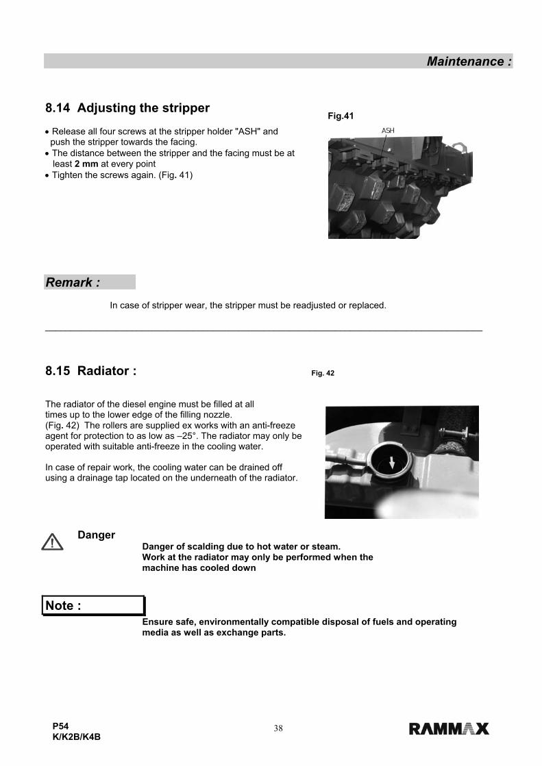
Maintenance : 8.14 Adjusting the stripper • Release all four screws at the stripper holder "ASH" and push the stripper towards the facing. • The distance between the stripper and the facing must be at least 2 mm at every point • Tighten the screws again. (Fig. 41) Remark : In case of stripper wear, the stripper must be readjusted or replaced. ______________________________________________________________________________________ 8.15 Radiator : The radiator of the diesel engine must be filled at all times up to the lower edge of the filling nozzle. (Fig. 42) The rollers are supplied ex works with an anti-freeze agent for protection to as low as –25°. The radiator may only be operated with suitable anti-freeze in the cooling water. In case of repair work, the cooling water can be drained off using a drainage tap located on the underneath of the radiator.
Danger Danger of scalding due to hot water or steam. Work at the radiator may only be performed when the
machine has cooled down
Note : Ensure safe, environmentally compatible disposal of fuels and operating
media as well as exchange parts.
Fig.41
Fig. 42
39P54 K/K2B/K4B
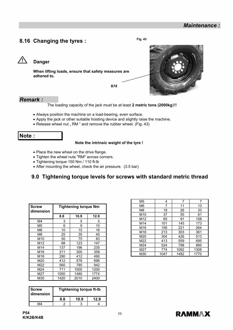
Maintenance : 8.16 Changing the tyres :
Danger
When lifting loads, ensure that safety measures are adhered to.
Remark : The loading capacity of the jack must be at least 2 metric tons (2000kg)!!! • Always position the machine on a load-bearing, even surface. • Apply the jack or other suitable hoisting device and slightly raise the machine. • Release wheel nut „ RM “ and remove the rubber wheel. (Fig. 43)
Note : Note the intrinsic weight of the tyre ! • Place the new wheel on the drive flange. • Tighten the wheel nuts "RM" across corners. • Tightening torque 150 Nm / 110 ft-lb • After mounting the wheel, check the air pressure. (3.5 bar)
9.0 Tightening torque levels for screws with standard metric thread
Screw dimension
Tightening torque Nm
8.8 10.9 12.9 M4 3 5 5 M5 6 9 10 M6 10 15 18 M8 25 35 45 M10 50 75 83 M12 88 123 147 M14 137 196 235 M16 211 300 358 M18 290 412 490 M20 412 578 696 M22 560 785 942 M24 711 1000 1200 M27 1050 1480 1774 M30 1420 2010 2400
Screw dimension
Tightening torque ft-lb
8.8 10.9 12.9 M4 2 3 4
M5 4 7 7 M6 7 11 13 M8 18 26 33 M10 37 55 61 M12 65 91 108 M14 101 145 173 M16 156 221 264 M18 213 303 361 M20 304 426 513 M22 413 559 695 M24 524 798 885 M27 774 1092 1308 M30 1047 1482 1770
Fig. 43
RM

P54 40 K/K2B/K4B
Maintenance : Strength classes for screws with untreated, unlubricated surface. The screw quality designation is indicated on the screw heads. 8.8 = 8G ; 10.9 = 10K ; 12.9 = 12K The values result in 90% utilization of the screw yield strength, with a coefficient of abrasion of µ total = 0.14. Adherence to the tightening torque levels is checked using a torque wrench. When using lubricant MoSo2, the specified tightening torque levels do not apply.
Remark : Self-locking nuts must be renewed after dismantling !

P54 41 K/K2B/K4B
Troubleshooting table :
10.0 Troubleshooting table
Fault : Possible cause : Remedy : Vibration does not work ! Pusher blade not in uppermost
position. - Move pusher blade to uppermost position
Engine running, machine does not move !
Insufficient hydraulic oil in the tank. Pedal valve defective
- Check hydraulic oil level - Check the hydraulic system for leaks - Check the pedal valve function
Engine does not start up ! No contact for limit switch under driver's seat.
- Check seat setting Page 27 Section 6.0

OPERATIONS MANUAL
Your Local Dealer is:
HERE'S HOW TO GET HELPPLEASE HAVE THE MODEL AND SERIAL
NUMBER ON-HAND WHEN CALLING
© COPYRIGHT 2006, MULTIQUIP INC.
Multiquip Inc, the MQ logo and the Rammax logo are registered trademarks of Multiquip Inc. and may not be used, reproduced, or altered without written permission. Allother trademarks are the property of their respective owners and used with permission.
This manual MUST accompany the equipment at all times. This manual is considered a permanent part of the equipment and should remain with the unit if resold.
The information and specifications included in this publication were in effect at the time of approval for printing. Illustrations are based on the P54K-K2B-K4B Ride-OnVibratory Roller. Illustrations, descriptions, references and technical data contained in this manual are for guidance only and may not be considered as binding. MultiquipInc. reserves the right to discontinue or change specifications, design or the information published in this publication at any time without notice and without incurring anyobligations.
UNITED STATESMultiquip Corporate Office MQ Parts Department18910 Wilmington Ave. Tel. (800) 421-1244 800-427-1244 Fax: 800-672-7877Carson, CA 90746 Fax (800) 537-3927 310-537-3700 Fax: 310-637-3284Contact: [email protected] Parts Warranty Department800-306-2926 Fax: 800-672-7877 800-421-1244, Ext. 279 Fax: 310-537-1173310-537-3700 Fax: 310-637-3284 310-537-3700, Ext. 279Service Department Technial Assistance800-421-1244 Fax: 310-537-4259 800-478-1244 Fax: 310-631-5032310-537-3700
MEXICO UNITED KINGDOMMQ Cipsa Multiquip (UK) Limited Head OfficeCarr. Fed. Mexico-Puebla KM 126.5 Tel: (52) 222-225-9900 Hanover Mill, Fitzroy Street, Tel: 0161 339 2223Momoxpan, Cholula, Puebla 72760 Mexico Fax: (52) 222-285-0420 Ashton-under-Lyne, Fax: 0161 339 3226Contact: [email protected] Lancashire OL7 0TL
Contact: [email protected]
CANADA BRAZILMultiquip Multiquip4110 Industriel Boul. Tel: (450) 625-2244 Av. Evandro Lins e Silva, 840 - grupo 505 Tel: 011-55-21-3433-9055Laval, Quebec, Canada H7L 6V3 Fax: (450) 625-8664 Barra de Tijuca - Rio de Janeiro Fax: 011-55-21-3433-9055Contact: [email protected] Contact: [email protected], [email protected]


![C-20140225 DP6 presentatie K2B TU Noord.ppt ... … · Title: Microsoft PowerPoint - C-20140225 DP6 _presentatie K2B TU Noord.ppt [Compatibiliteitsmodus] Author: jmo](https://img.dokumen.tips/doc/110x75/6037217bdc81e740a7002db9/c-20140225-dp6-presentatie-k2b-tu-noordppt-title-microsoft-powerpoint-.jpg)


![K4B FINAL - 50135095k muhammad shofiulloh [autosaved]](https://img.dokumen.tips/doc/110x75/5876bfe51a28ab6d5a8b4a5b/k4b-final-50135095k-muhammad-shofiulloh-autosaved-58bc4625d94ba.jpg)