Embed Size (px)
Citation preview
Filter Banks – IIMulti-Rate Signal Processing
Dr. Yogananda Isukapalli
2
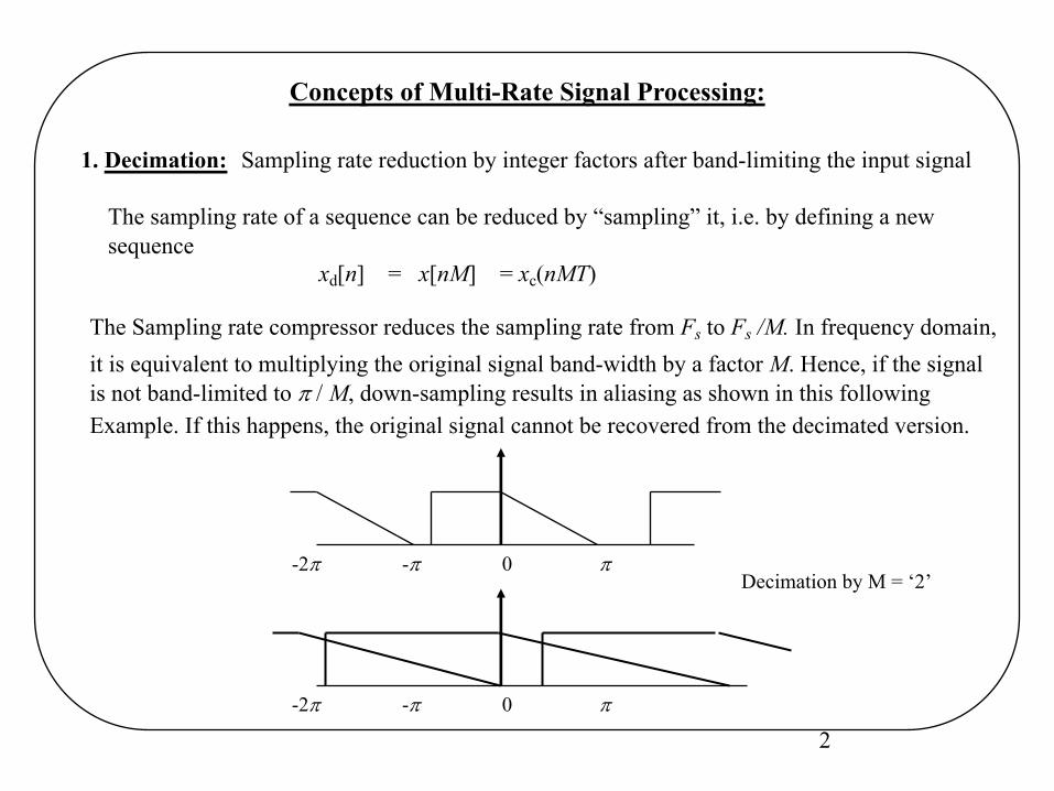
Concepts of Multi-Rate Signal Processing:
1. Decimation: Sampling rate reduction by integer factors after band-limiting the input signal
The sampling rate of a sequence can be reduced by “sampling” it, i.e. by defining a new sequence
xd[n] = x[nM] = xc(nMT)
The Sampling rate compressor reduces the sampling rate from Fs to Fs /M. In frequency domain,it is equivalent to multiplying the original signal band-width by a factor M. Hence, if the signal is not band-limited to p / M, down-sampling results in aliasing as shown in this following Example. If this happens, the original signal cannot be recovered from the decimated version.
-2p -p 0 p
-2p -p 0 p
Decimation by M = ‘2’
3
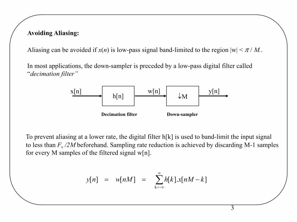
Avoiding Aliasing:
Aliasing can be avoided if x(n) is low-pass signal band-limited to the region |w| < p / M..
In most applications, the down-sampler is preceded by a low-pass digital filter called“decimation filter”
¯Mx[n]
h[n]w[n] y[n]
Decimation filter Down-sampler
To prevent aliasing at a lower rate, the digital filter h[k] is used to band-limit the input signal to less than Fs /2M beforehand. Sampling rate reduction is achieved by discarding M-1 samples for every M samples of the filtered signal w[n].
å¥
¥=
-==-k
][].[ ][ ][ knMxkhnMwny
4
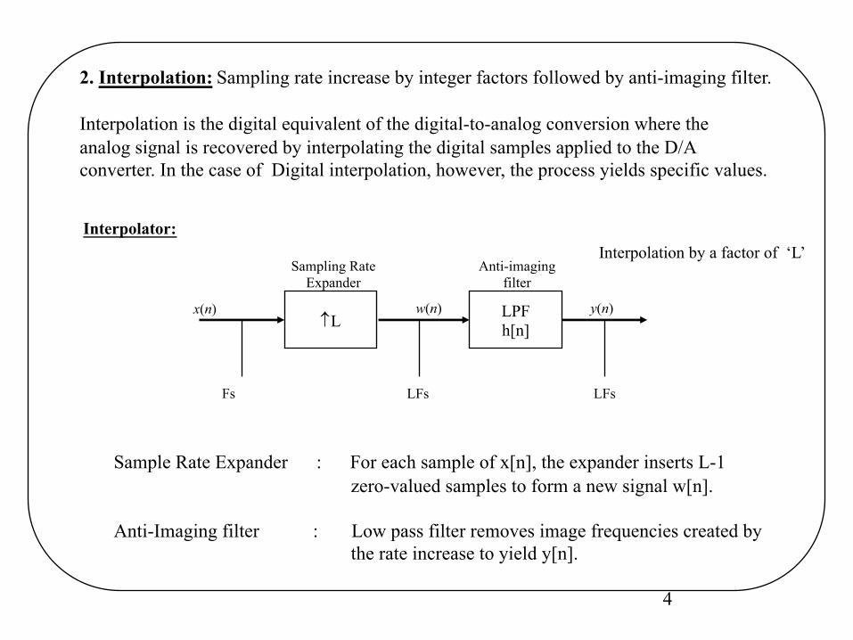
2. Interpolation: Sampling rate increase by integer factors followed by anti-imaging filter.
Interpolation is the digital equivalent of the digital-to-analog conversion where the analog signal is recovered by interpolating the digital samples applied to the D/A converter. In the case of Digital interpolation, however, the process yields specific values.
Interpolator:
LPFh[n]
x(n)L
w(n)
LFs
y(n)
Fs LFs
Sampling RateExpander
Anti-imagingfilter
Sample Rate Expander : For each sample of x[n], the expander inserts L-1 zero-valued samples to form a new signal w[n].
Anti-Imaging filter : Low pass filter removes image frequencies created by the rate increase to yield y[n].
Interpolation by a factor of ‘L’
5
å¥
¥=
-=-k
][].[ ][ knwkhny
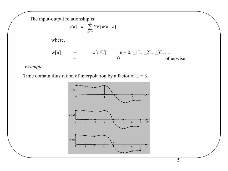
The input-output relationship is:
where,
w[n] = x[n/L] n = 0, +1L, +2L, +3L,….= 0 otherwise.
Time domain illustration of interpolation by a factor of L = 3.
Example:
6
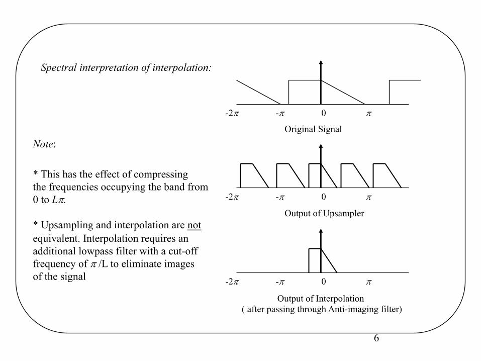
Spectral interpretation of interpolation:
Note:
* This has the effect of compressingthe frequencies occupying the band from 0 to Lp.
* Upsampling and interpolation are notequivalent. Interpolation requires anadditional lowpass filter with a cut-offfrequency of p /L to eliminate imagesof the signal
-2p -p 0 p
Output of Upsampler
-2p -p 0 p
Output of Interpolation ( after passing through Anti-imaging filter)
-2p -p 0 p
Original Signal
7
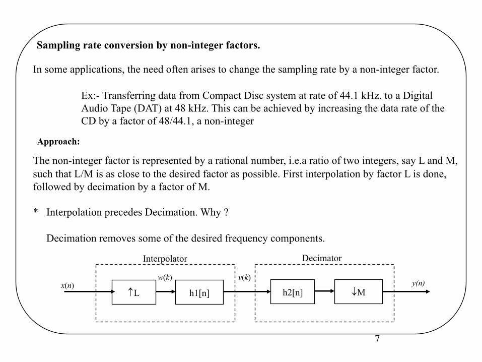
Sampling rate conversion by non-integer factors.
In some applications, the need often arises to change the sampling rate by a non-integer factor.
Ex:- Transferring data from Compact Disc system at rate of 44.1 kHz. to a Digital Audio Tape (DAT) at 48 kHz. This can be achieved by increasing the data rate of the CD by a factor of 48/44.1, a non-integer
Approach:
The non-integer factor is represented by a rational number, i.e.a ratio of two integers, say L and M, such that L/M is as close to the desired factor as possible. First interpolation by factor L is done,followed by decimation by a factor of M.
* Interpolation precedes Decimation. Why ?
Decimation removes some of the desired frequency components.
h1[n]x(n)
Ly(n)
¯Mh2[n]
Interpolator Decimator
w(k) v(k)
8
h1[n]x(n)
Ly(n)
¯M
w(k)
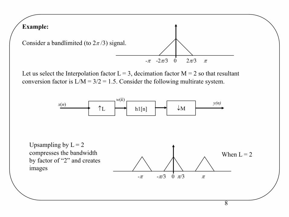
Example:
-p -2p/3 0 2p/3 p
Consider a bandlimited (to 2p /3) signal.
-p -p/3 0 p/3 p
When L = 2Upsampling by L = 2compresses the bandwidthby factor of “2” and createsimages
Let us select the Interpolation factor L = 3, decimation factor M = 2 so that resultant conversion factor is L/M = 3/2 = 1.5. Consider the following multirate system.
9
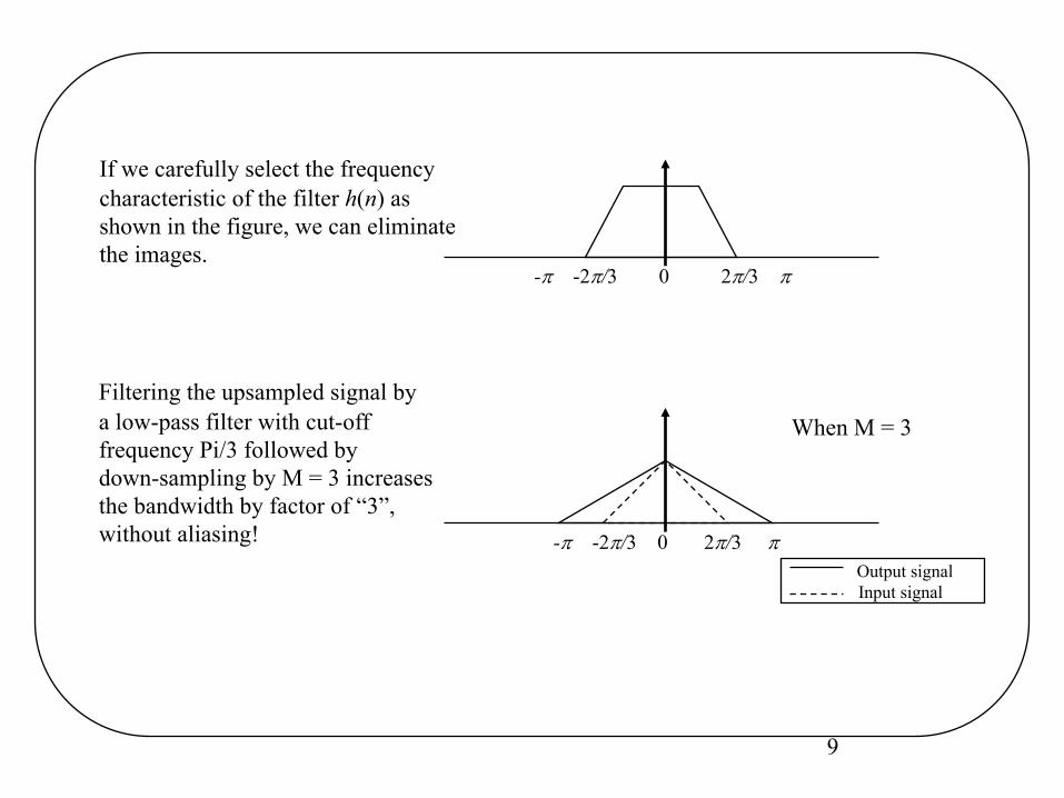
Filtering the upsampled signal bya low-pass filter with cut-off frequency Pi/3 followed by down-sampling by M = 3 increasesthe bandwidth by factor of “3”,without aliasing!
-p -2p/3 0 2p/3 p
If we carefully select the frequencycharacteristic of the filter h(n) asshown in the figure, we can eliminatethe images.
When M = 3
-p -2p/3 0 2p/3 pOutput signalInput signal
10
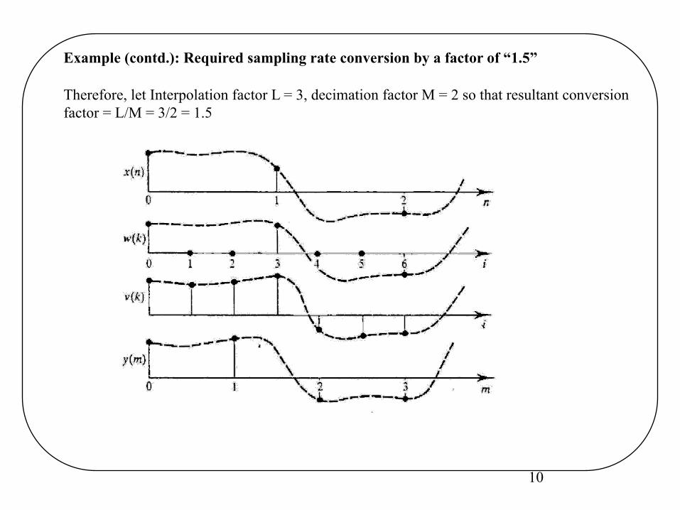
Example (contd.): Required sampling rate conversion by a factor of “1.5”
Therefore, let Interpolation factor L = 3, decimation factor M = 2 so that resultant conversion factor = L/M = 3/2 = 1.5
11
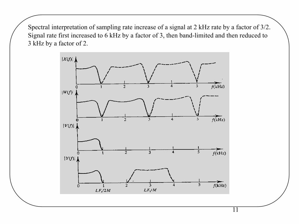
Spectral interpretation of sampling rate increase of a signal at 2 kHz rate by a factor of 3/2. Signal rate first increased to 6 kHz by a factor of 3, then band-limited and then reduced to 3 kHz by a factor of 2.
12
Examples
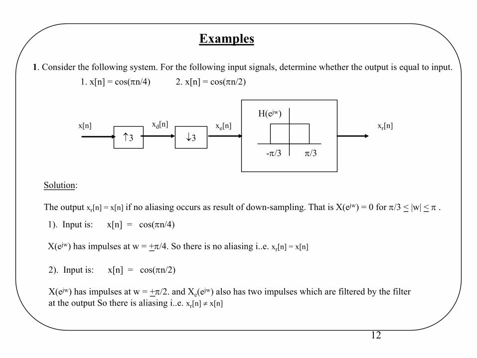
1. Consider the following system. For the following input signals, determine whether the output is equal to input.1. x[n] = cos(pn/4) 2. x[n] = cos(pn/2)
x[n]
¯33
-p/3 p/3
H(ejw)xr[n]xd[n] xe[n]
1). Input is: x[n] = cos(pn/4)
X(ejw) has impulses at w = +p/4. So there is no aliasing i..e. xr[n] = x[n]
Solution:
The output xr[n] = x[n] if no aliasing occurs as result of down-sampling. That is X(ejw) = 0 for p/3 < |w| < p .
2). Input is: x[n] = cos(pn/2)
X(ejw) has impulses at w = +p/2. and Xe(ejw) also has two impulses which are filtered by the filter at the output So there is aliasing i..e. xr[n] ¹ x[n]
13
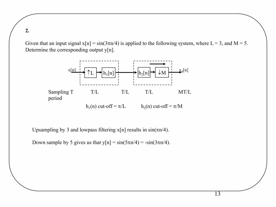
2.
Given that an input signal x[n] = sin(3pn/4) is applied to the following system, where L = 3, and M = 5.Determine the corresponding output y[n].
Upsampling by 3 and lowpass filtering x[n] results in sin(pn/4).
Down sample by 5 gives us that y[n] = sin(5pn/4) = -sin(3pn/4).
h1[n]x[n]L xd[n] ¯Mh2[n]
Sampling T T/L T/L T/L MT/Lperiod
h1(n) cut-off = p/L h2(n) cut-off = p/M
14
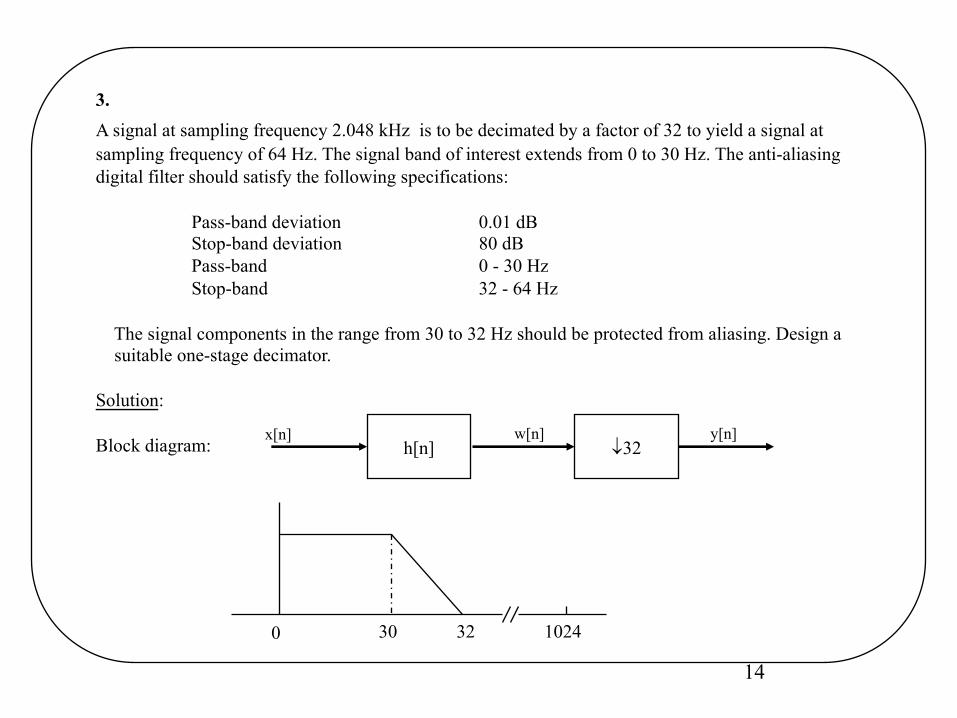
3.A signal at sampling frequency 2.048 kHz is to be decimated by a factor of 32 to yield a signal atsampling frequency of 64 Hz. The signal band of interest extends from 0 to 30 Hz. The anti-aliasingdigital filter should satisfy the following specifications:
Pass-band deviation 0.01 dBStop-band deviation 80 dBPass-band 0 - 30 HzStop-band 32 - 64 Hz
The signal components in the range from 30 to 32 Hz should be protected from aliasing. Design a suitable one-stage decimator.
Solution:
Block diagram: ¯32x[n]
h[n]w[n] y[n]
0 3230 1024
15
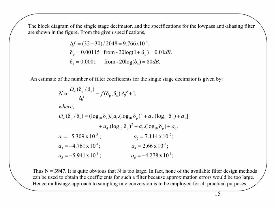
The block diagram of the single stage decimator, and the specifications for the lowpass anti-aliasing filterare shown in the figure. From the given specifications,
.80)20log(δ- from 0001.0δ
.01.0)δ 20log(1- from 00115.0δ.x10766.92048/)3032(
ss
pp
-4
dBdB
f
==
=+==-=D
An estimate of the number of filter coefficients for the single stage decimator is given by:
;10 x 278.4 ; 10 x 941.5
;10 x 66.2 ;10 x 761.4
;10 x 114.7 ; 10 x 309.5
.)δ.(log)δ.(log
])δ.(log)δ.(log).[δ(log)δ/δ(,
,1).δ,δ()δ/δ(
1-6
1-5
3-4
1-3
2-2
3-1
6p1052
p104
3p1022
p101s10sp
spsp
-=-=
=-=
==
+++
++=
+D-D
»
¥
¥
aaaaaa
aaa
aaaDwhere
fff
DN
Thus N = 3947. It is quite obvious that N is too large. In fact, none of the available filter design methodscan be used to obtain the coefficients for such a filter because approximation errors would be too large.Hence multistage approach to sampling rate conversion is to be employed for all practical purposes.
16
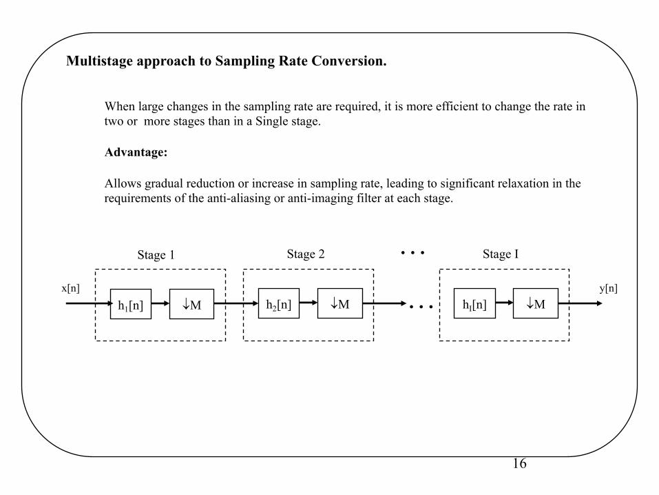
Multistage approach to Sampling Rate Conversion.
When large changes in the sampling rate are required, it is more efficient to change the rate intwo or more stages than in a Single stage.
Advantage:
Allows gradual reduction or increase in sampling rate, leading to significant relaxation in the requirements of the anti-aliasing or anti-imaging filter at each stage.
x[n]
¯Mh1[n] ¯Mh2[n] ¯MhI[n]…
Stage 1 Stage IStage 2 …y[n]
17
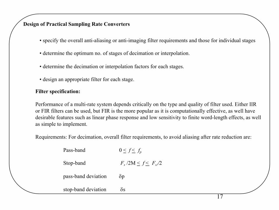
Design of Practical Sampling Rate Converters
• specify the overall anti-aliasing or anti-imaging filter requirements and those for individual stages
• determine the optimum no. of stages of decimation or interpolation.
• determine the decimation or interpolation factors for each stages.
• design an appropriate filter for each stage.
Filter specification:
Performance of a multi-rate system depends critically on the type and quality of filter used. Either IIRor FIR filters can be used, but FIR is the more popular as it is computationally effective, as well have desirable features such as linear phase response and low sensitivity to finite word-length effects, as wellas simple to implement.
Requirements: For decimation, overall filter requirements, to avoid aliasing after rate reduction are:
Pass-band 0 < f < fp
Stop-band Fs /2M < f < Fs//2
pass-band deviation dp
stop-band deviation ds
18
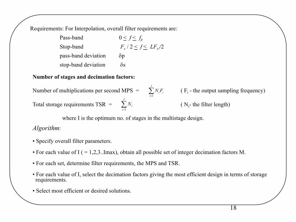
Requirements: For Interpolation, overall filter requirements are:
Pass-band 0 < f < fp
Stop-band Fs / 2 < f < LFs//2pass-band deviation dp
stop-band deviation ds
Number of stages and decimation factors:
Number of multiplications per second MPS = ( Fi - the output sampling frequency)
Total storage requirements TSR = ( Ni- the filter length)
where I is the optimum no. of stages in the multistage design.
å=
I
iiiFN
1
å=
I
iiN
1
Algorithm:
• Specify overall filter parameters.
• For each value of I ( = 1,2,3..Imax), obtain all possible set of integer decimation factors M.
• For each set, determine filter requirements, the MPS and TSR.
• For each value of I, select the decimation factors giving the most efficient design in terms of storagerequirements.
• Select most efficient or desired solutions.
19
Application ExampleAudio Engineering:
Digital Audio Engineering is an area that has been benefited significantly from MultirateTechniques.
• In A/D conversion process, High quality digital data is obtained from analog data by combining multirate processing with delta modulation techniques
• Simplified the D/A conversion process
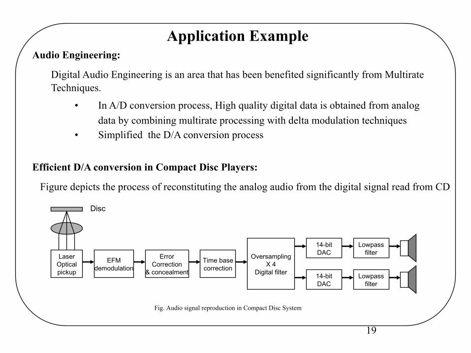
Efficient D/A conversion in Compact Disc Players:
Figure depicts the process of reconstituting the analog audio from the digital signal read from CD
LaserOpticalpickup
EFMdemodulation
ErrorCorrection
& concealment
Time basecorrection
OversamplingX 4
Digital filter
14-bitDAC
14-bitDAC
Lowpassfilter
Lowpassfilter
Fig. Audio signal reproduction in Compact Disc System
Disc
20
After decoding, the digital signals are in 16-bit words representing the acoustic informationat a 44.1 kHz sampling rate which are needed to be converted into analog.
• If the digital codes are directly converted into analog, it causes overloading on the player’s amplifier and set up intermodulation distortion, also needs analog filterswith tight specification (sharp transition from passband to stopband, and high attenuation in stop band).
Use of Multirate processing:
To avoid problems with analog filters, multirate filtering is employed.
Achieved by first increasing, by interpolation, the sampling rate of data by 4 to 176 kHz(4 x 44.1 = 176.4 kHz) before it can be applied to the DAC. The effects of this are:
• In time domain, the image frequencies are pushed to higher frequencies, making itit easier to filter them out, using a relatively simple lowpass filter
• Also, reduces the noise as the noise is spread over a wider bandwidth.
21
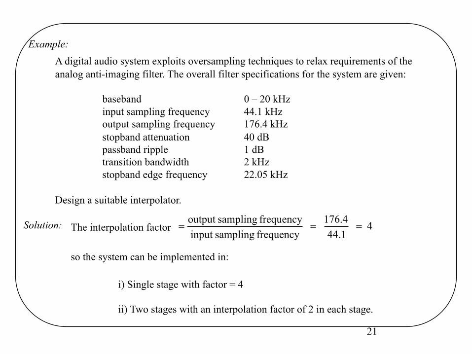
A digital audio system exploits oversampling techniques to relax requirements of the analog anti-imaging filter. The overall filter specifications for the system are given:
baseband 0 – 20 kHzinput sampling frequency 44.1 kHzoutput sampling frequency 176.4 kHzstopband attenuation 40 dBpassband ripple 1 dBtransition bandwidth 2 kHzstopband edge frequency 22.05 kHz
Design a suitable interpolator.
Solution:
Example:
The interpolation factor
so the system can be implemented in:
i) Single stage with factor = 4
ii) Two stages with an interpolation factor of 2 in each stage.
4 44.1
176.4
frequency samplinginput frequency samplingoutput
===
22
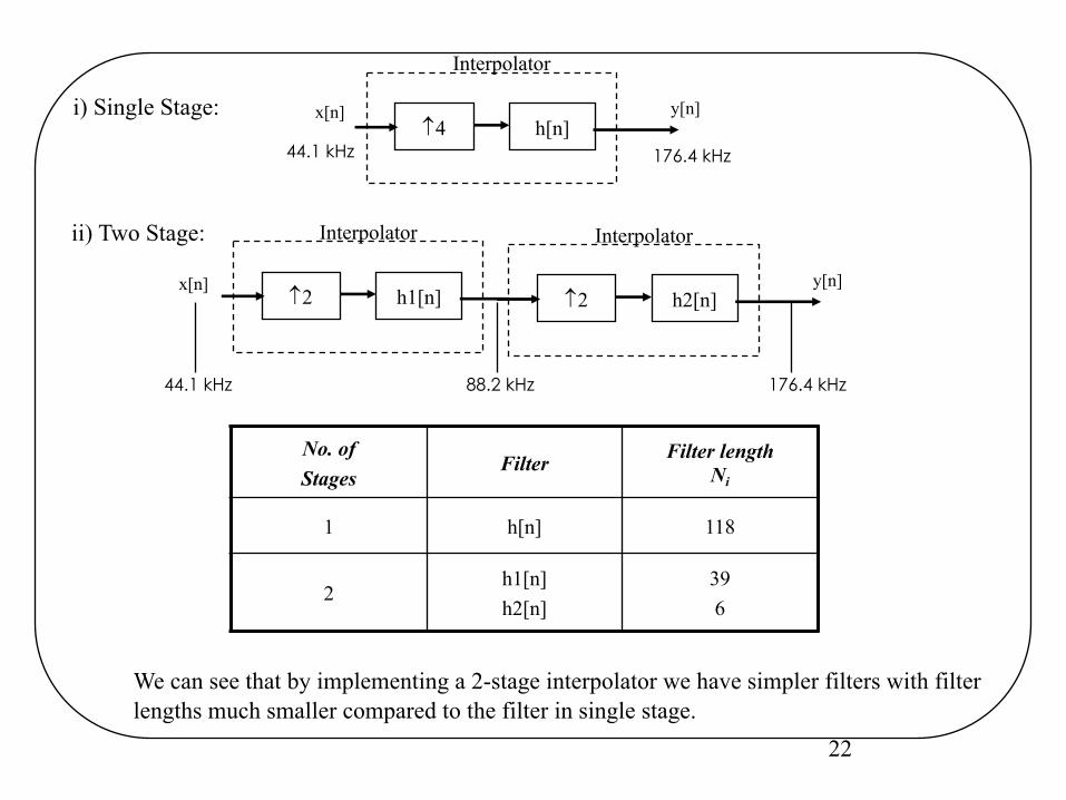
h1[n]2
Interpolator
x[n] y[n]h2[n]2
Interpolator
y[n]h[n]4
Interpolator
x[n]
44.1 kHz 176.4 kHz
44.1 kHz 88.2 kHz 176.4 kHz
We can see that by implementing a 2-stage interpolator we have simpler filters with filterlengths much smaller compared to the filter in single stage.
i) Single Stage:
ii) Two Stage:
No. ofStages
Filter Filter lengthNi
1 h[n] 118
2h1[n]h2[n]
396