Embed Size (px)
Citation preview

OWNER’S MANUAL
ZTU and ZTU PanE-Z Reach Container Tilters
Southworth Products CorpP.O. Box 1380/ Portland, ME 04104-1380
Telephone: 207-878-0700 Fax: 207-797-4734
Model #
Serial #
Placed In Service
June 2015

2 ZTU SERIES — EZ REACH OWNER’S MANUAL
ZTU EZ REACH
Please note: This manual was current at the time of printing.To obtain the latest, most updated version, please contact
Southworth’s Customer Service Department or go to our website: www.SouthworthProducts.com, under Parts & Service
you will find a complete list of currentowner’s manuals to print.

Owner’s Manual SOUTHWORTH
ZTU SERIES — EZ REACH OWNER’S MANUAL 3
ContentsINTRODUCTION ............................................................................................................4RESPONSIBILITY OF OWNERS AND USERS ..............................................................5SAFETY ..........................................................................................................................6INSTALLATION INSTRUCTIONS ..................................................................................6 Preparation ........................................................................................................6 Positioning the Lift .............................................................................................6 Hydraulic Connections .......................................................................................7 Hydraulic Oil Specifications ................................................................................7 Electrical Connections ........................................................................................8 Testing ...............................................................................................................8OPERATING INSTRUCTIONS .......................................................................................9 Safety Alert Symbols and Signal Words .............................................................9 Labels and Precautionary Markings .................................................................10 Operating Procedure ........................................................................................ 11MAINTENANCE ...........................................................................................................13 Hazards ...........................................................................................................13 Routine Periodic Maintenance .........................................................................13 Repacking Cylinders .........................................................................................14 Troubleshooting Check List .............................................................................14ORDERING REPLACEMENT PARTS...........................................................................152 YEAR WARRANTY ....................................................................................................20
List of FiguresFig. 1 Installing the Unit ............................................................................... 7Fig. 2 Pinch Points ....................................................................................... 8Fig. 3 Safety Markings ............................................................................... 10Fig. 4 Push the Load Back ......................................................................... 10Fig. 5 Correct Load Center Ranges ............................................................11Fig. 6 Center the Load ................................................................................11Fig. 7 Don’t Overfill the Container .............................................................. 12Fig. 8 Hydraulic Pump................................................................................ 16Fig. 9 Down Valve ...................................................................................... 16Fig. 10 Electrical Diagram ............................................................................ 17Fig. 11 Hydraulic Diagram ........................................................................... 17Fig. 12 Parts Identification - Side View (ZTU-2, ZTU-4) .............................. 18Fig. 13 Parts Identification - Front View (ZTU-2, ZTU-4, ZTU-2 Pan) .......... 19Fig. 14 Parts Identification - Front View (ZTU-4 Pan) .................................. 19

4 ZTU SERIES — EZ REACH OWNER’S MANUAL
ZTU EZ REACH
IntroductionThe Southworth ZTU and ZTU-Pan E-Z Reach Container Tilters are designed to position parts containers at a convenient working height. This allows work-ers to reach the parts without bending or stretching. Both types feature floor-height roll-on designs. This allows containers to be placed directly on the tilter in a single step, using a fork truck or hand pallet truck. The ZTU models have two separate lifting arms and are designed to lift loads which are delivered by a pallet jack. On the ZTU-Pan units, the two arms are connected by a pan which may be lowered to floor level. This allows a load to be tilted while it is still on the pallet. The two types are identified on the front cover. Two models of each type are available for maximum load capacities of 2,000 lbs and 4,000 lbs. Using a pushbutton control the operator can position the load at any angle between 0° and 85°.
This manual contains instructions on the safe and proper installation, use, and maintenance of a ZTU-or ZTU-Pan series tilter. Be sure that this manual is available to the people who install, use, or service the E-Z Reach unit. Be sure that all personnel read this manual before they install, use or service the unit.
EZ-Reach units may be used in a wide variety of industrial settings. The instructions in this manual are not necessarily all-inclusive, as Southworth cannot anticipate all conceivable or unique situations. In the interest of safety, please read this whole manual carefully. Please understand the material in this manual before you install, use, or service the E-Z Reach unit. If you have any questions about any of the instructions in this manual, please contact Southworth Products Corporation.
Southworth’s product warranty is shown on the rear cover of this manual. This instruction manual is not intended to be or to create any other warranty, express or implied, including any implied warranty of merchantability or fitness for a particular purpose, all of which are hereby expressly excluded. As set forth more specifically in the product warranty, Southworth’s obligation under that warranty is limited to the repair or replacement of defective components, which shall be the buyer’s sole remedy, and Southworth shall not be liable for any loss, injury, or damage to persons or property, nor for any direct, indirect, or consequential damage of any kind resulting from the EZ-Reach Container Tilter.

Owner’s Manual SOUTHWORTH
ZTU SERIES — EZ REACH OWNER’S MANUAL 5
Responsibility of Owners and Users
Inspection and MaintenanceThe device shall be inspected and maintained in proper working order in accordance with Southworth’s owner’s manual.
Removal from ServiceAny device not in safe operating condition such as, but not limited to, excessive leakage, missing rollers, pins, or fasteners, any bent or cracked structural members, cut or frayed electric, hydraulic, or pneumatic lines, damaged or malfunctioning controls or safety de-vices, etc. shall be removed from service until it is repaired to the original manufacturer’s standards.
DeflectionIt is the responsibility of the user/purchaser to advise the manufacturer where deflection may be critical to the application.
RepairsAll repairs shall be made by qualified personnel in conformance with Southworth’s instruc-tions.
OperatorsOnly trained personnel and authorized personnel shall be permitted to operate the lift.
Before OperationBefore using the device, the operator shall have:
• Read and/or had explained, and understood, the manufacturer’s operating instruc-tions and safety rules.
• Inspected the device for proper operation and condition. Any suspect item shall be carefully examined and a determination made by a qualified person as to whether it constitutes a hazard. All items not in conformance with Southworth’s specification shall be corrected before further use of the equipment.
During OperationThe device shall only be used in accordance with this owner’s manual.
• Do not overload.• Ensure that all safety devices are operational and in place.
Modifications or AlterationsModifications or alterations to any Southworth industrial positioning equipment shall be made only with written permission from Southworth.

6 ZTU SERIES — EZ REACH OWNER’S MANUAL
ZTU EZ REACH
Installation InstructionsPreparation1. Before you start to use the unit, check for local codes and ordinances which may apply. It is your re-sponsibility to obtain any necessary permits.2. Read all of these installation instructions carefully. Be sure to read and understand all of the warnings.3. The unit should only be used indoors, or it should be protected from the weather.
WARNING!• Protect the unit from rain or moisture. If the electrical parts in the power unit get wet, workers may be hurt by electrical shock. The electrical parts may fail if they are wet.
SafetyThe safety of all persons installing, using, servicing, or working near the EZ-Reach unit is of paramount concern to Southworth. The EZ-Reach unit is a powerful machine with moving parts, and is capable of causing personal injury if proper precautions are not taken.
Therefore, throughout this manual, Southworth has identified certain hazards which may oc-cur in the use of the EZ-Reach unit, and provided appropriate instructions or precautions which should be taken to avoid these hazards. In some cases, Southworth has also pointed out the consequences which may occur if Southworth’s instructions or precautions are not followed. Southworth uses the following system of identifying the severity of the hazards as-sociated with its products:
DANGER – Immediate hazard which will result in severe personal injury or death.
WARNING – Hazard or unsafe practice that could result in severe personal injury or death.
CAUTION – Hazard or unsafe practice that could result in minor personal injury or property damage.
Please read and follow this instruction manual, including all safety instructions and precautions, carefully and completely.
CAUTION!• This unit has an electric motor that can create sparks. Don’t use the unit in an area where flammable gases may be present.
4. You will need these tools to install the unit:• A crane or lift truck that can lift the unit safely.• Shims and lag bolts.• A masonry drill and bit to drill the holes for the lag bolts.• Wrenches to fit the lag bolts.
POSITIONING THE UNIT1. Remove the shipping material and unskid the unit. You will need a crane or lift truck that can lift the unit safely.

Owner’s Manual SOUTHWORTH
ZTU SERIES — EZ REACH OWNER’S MANUAL 7
CAUTION!Do not try to move the lift by supporting the tilt platform. One end of the tilt platform is free.
On the front of this manual, write down the model num-ber, serial number, and date the unit is placed in service. You can find the model number and serial number on the nameplate.
WARNING!If the unit is mounted on an unstable sur-face, it may tip over when it is in use. You may be hurt, and the unit and load may be damaged.
Changing the Hydraulic FluidThe procedure depends on the type of unit you have. In order to change the fluid, lower the tilt platform com-pletely and unplug the power cord. Remove the rear cover on the unit.ZTU-2 (2,000 capacity unit) - 120V AC unit: The tank is located below the motor and pump. The tank is nor-mally filled through the vent plug (connected to the clear plastic vent line). Since it is very hard to reach this plug from the rear of the unit, and the tilt platform is stopped in the lowered position, it is easiest to remove the tank. Disconnect the hydraulic hose which runs to the bottom of the pump. Undo the connection just below the pump. Disconnect the upper end of the clear plastic
vent line. Finally, unbolt the tank and remove it. Remove the vent plug. Pour out the old fluid and add fresh fluid. Use a dipstick to check the oil level. This should be 1/2’’ to 3/4’’ (13 to 19 mm) below the top of the tank. Add oil as necessary. Replace the tank and reconnect the hoses.ZTU-4 (4,000 capacity unit) - 120V AC unit: The tank is located in the left-hand support leg of the unit (when viewed from the rear). See Fig. 14. To drain the tank, loosen the fitting at the bottom of the leg. Remove the filler cap, and check the level with a dipstick. The oil should be 1/2’’ to 3/4’’ (13 to 19 mm) below the top of the tank. Add oil as necessary.
Table 1 – Hydraulic Oil Specifications
If the lift will be used at normal ambient temperatures, Southworth supplies the unit with CONOCO 32 oil. This may be replaced by any other good quality oil with 150 SSU at 100° F and rust and oxidation inhibitors and anti-wear properties. If the lift will be used at ambient temperatures below 0°F, use aircraft hydraulic oil. Use Type 15 aircraft hydraulic oil.
The following are equivalent to CONOCO 32: TYPE .......................MANUFACTURER DTE 24 ....................EXXON/MOBILNUTO H32 ...............EXXON/MOBILAMOCO AW32 ........CHEVRON (AMOCO CO.)CITGO AW32 ............CITGO
CAUTION! It is very important to keep the hydraulic oil free of dirt, dust, metal chips, water, and other contamination. Most of the problems with hydraulic systems are caused by contamination in the oil.

8 ZTU SERIES — EZ REACH OWNER’S MANUAL
ZTU EZ REACH
ELECTRICAL CONNECTIONS1. The unit has a power cord which is 10’ long (305 cm). At each location where you want to use the unit, be sure a three-prong outlet is available. Each circuit should have a 20 amp dedicated circuit breaker or fuse.
DANGER!The unit uses a power supply of 115 volts AC. This voltage can kill you. Don’t work with the electrical parts unless you are a qualified electrician.
WARNING!To avoid fire danger, be sure to provide a circuit breaker or fuse.
2. The foot switch assembly is attached to the unit by a 3’ cable (91 cm). Position the control box in a convenient location near the unit.3. Check the level of the hydraulic fluid in the tank. In order to check the level, lower the unit completely and unplug the power cord. Remove the rear cover on the unit. The tank is located below the motor and pump. The tank is normally filled through the vent plug (connected to the clear plastic vent line). To check the level, remove the vent plug. Use a dipstick to check the oil level. The oil should be 1/2’’ to 3/4’’ (13 to 19 mm) below the top of the tank. Add oil as necessary.
Fig. 2. Pinch Points
Testing1. Clear the area around the unit, and warn others to stay away from the unit. Remove any loose wires, lumber, or other materials which might get in the way of the unit as it raises or lowers.2. Operate the unit through its full range of travel. The unit should rise smoothly with a quiet humming sound, and lower smoothly and quietly. Raise and lower the unit a few times to check the clearances around the tilt platform.
WARNING!As the tilt platform moves up and down, “pinch points” are created at the places shown in Fig. 2. If you are standing too close to the unit when it is moving, your arm or leg may be caught in the moving parts, and you may be hurt. Stay away from the pinch points when the unit is moving.
3. If the unit is lowering too quickly or too slowly, you can change the “down speed” by adjusting the flow control.

Owner’s Manual SOUTHWORTH
ZTU SERIES — EZ REACH OWNER’S MANUAL 9
If you want the tilt platform to lower more slowly, turn the control clockwise up to 1/4 turn at a time. If you want the tilt platform to lower more quickly, turn the control counterclockwise up to 1/4 turn. Don’t move the control more than 1/4 turn at a time.4. Test the unit with the rated load. If the unit does not rise, and you hear a loud squealing noise, the pressure relief valve is operating. Contact Southworth for instructions.
WARNING!Don’t continue to use the unit if this happens – the pump will overheat very quickly, and may be permanently damaged. Do not try to adjust the relief valve. If you change the setting on the relief valve, you may overwork the unit. This can cause the unit to fail suddenly, and you may be hurt.
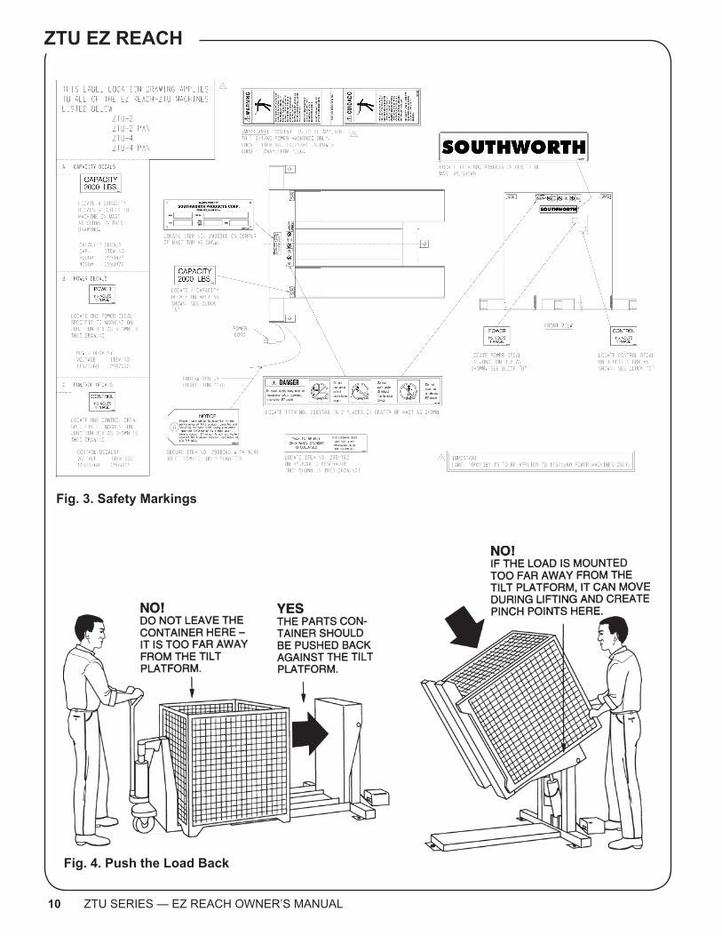
5. Clean up any spilled hydraulic fluid. Spilled hydraulic oil is slippery, and may present a fire hazard. If you clean up any spilled fluid, you will be able to tell right away if the unit begins to leak.6. Figure 3 shows the safety labels on this unit. Check to be sure all of the labels are in place.
SAFETY ALERT SYMBOLS AND SIGNAL WORDSThe safety of all persons operating, maintaining, repairing, or in the vicinity of this equipment is of paramount concern. This is a powerful machine with moving parts, and is capable of causing personal injury if proper precautions are not taken. Therefore, throughout this manual, certain hazards have been identified which may occur in the use of the machine, and there are appropriate instructions or precautions which should be taken to avoid these hazards. In some cases, there are consequences which may occur if instructions or precautions are not followed. Below are the symbols and signal words along with their definitions referenced from ANSI Z535.4 - Product Safety Signs and Labels.
Safety Alert SymbolsThese are the safety alert symbols.. They are used to alert you to potential physical injury hazards. Obey all safety messages that follow this symbol to avoid possible injury or death.
For use with DANGER signal word(Red Background)
For use with WARNING signal word(Orange Background)
For use with CAUTION signal word(Yellow Background)
Signal WordsThe meaning of different signal words as defined by ANSI Standard Z535.4 indicates the relative seriousness of the hazardous situation.
DANGER indicates a hazardous situation which, if not avoided, will result in death or serious injury.
WARNING indicates a hazardous situation which, if not avoided, could result in death or serious injury.
CAUTION, used with the safety alert symbol, indicates a hazardous situation which, if not avoided, could result in minor or moderate injury.
NOTICE is used to address practices not related to per-sonal injury.
(Red Background)
(Orange Background)
(Yellow Background)
(Blue Background)
SAFETYINSTRUCTIONS
SAFETY INSTRUCTIONS (or equivalent) signs indicate safety-related instructions or procedures.
(Green Background)
10 ZTU SERIES — EZ REACH OWNER’S MANUAL
ZTU EZ REACH
Fig. 4. Push the Load Back
Fig. 3. Safety Markings

Owner’s Manual SOUTHWORTH
ZTU SERIES — EZ REACH OWNER’S MANUAL 11
For ZTU models, the load center may be up to 20’’ from the tilt platform. For ZTU-Pan models, the load center may be up to 24’’ from the platform. When lifting, always keep the load center as close as possible to the tilt platform. When either kind of unit is lifting the type of load for which it was designed, the unit will be able to lift the full rated load. If a unit is used for a different type of load, with a different center of load, it may not be able to lift the rated load safely. If you plan to begin lifting a different type of load, consult the factory for details.
WARNING!Don’t try to lift a load that exceeds the maxi-mum rating. Only lift a load if the center of load is within the allowable range. If you do not follow these rules, the unit may fail suddenly. Someone may be hurt, and the unit and load may be damaged.
3. The load should be balanced in the side-to-side direction. Whenever possible, place the load in the center of the tilting platform, as shown in Fig. 6. If the load is off-center on the pallet, place the heaviest part of the load near the back of the tilt platform – never near the front!4. Sometimes the unit may be used to lift parts which can roll. If possible, stack the parts in the parts container so they cannot roll. Do not overfill the lifting container. See Fig. 7. If the container is too full, some of the parts may roll out of the front of the container.
Center of load
2193.1
20"
17"
Operating ProcedureLoading the unit1. Before operating the unit, please read and under-stand this entire section.
DANGER!This unit uses a power supply of 115 Volts AC. This voltage can kill you. Don’t work with the electrical parts unless you are a qualified electrician!
2. Load the unit correctly.Before lifting, be sure the lifting container is pushed against the tilting platform, as shown in Fig. 4. If you do not do this, the container may slide down and create dangerous “pinch points.”Be sure that the load weighs no more than the maximum rated for the unit. The maximum rated load is listed on the tilt platform. Remember that the lifting container may weigh 75 lbs. or more. Push the load back against the tilt platform.
WARNING!The tilt platform should always be pushed against the load. If the load is placed far out on the lifting arms, the unit may not be able to lift the full rated load safely. See Fig. 5.
Fig. 5. Correct Load Center Ranges
ZTU Models - Load center may be up to 20’’ from the tilt platform ZTU-2 Max. load 2,000 lb. ZTU-4 Max. load 4,000 lb.ZTU Pan Models - Load center may be up to 24’’ from the tilt platform ZTU-2 Pan Max. load 2,000 lb. ZTU-4 Pan Max. load 4,000 lb.
ZTU20’’ or less;
ZTU-Pan 24’’ or less
Fig. 6. Center the Load

12 ZTU SERIES — EZ REACH OWNER’S MANUAL
ZTU EZ REACH
WARNING!Don’t overfill the lifting container. As the unit lifts, some of the parts may roll out of the front of the container. The falling parts may hurt you or damage the unit.
Raising the Tilt Platform1. Before raising the tilt platform, be sure all workers are clear of the unit.
WARNING!As the tilt platform moves up and down, “pinch points” are created as shown in Fig. 2. Stay away from these pinch points! Part of your body or clothing may become caught, and you may be hurt. Do not put your hands or feet under the tilt platform. Do not stand or sit on the tilt platform.
2. Before lifting, be sure the parts container is pushed up against the tilt platform, as shown in Fig. 4. Be sure the load is balanced side-to-side, as shown in Fig. 6.3. Plug in the AC cord. Be sure the cord cannot be-come caught in the moving parts as the platform raises.
WARNING!Be sure that the electrical power cord will not be pinched by the unit as it raises or
lowers. If you allow the cord to be pinched, it may be broken. This can create a shock hazard. To avoid this problem, always check the position of the cord before you start to raise or lower the unit.
5. Operate the unit. Press and hold the Up button to raise the tilt platform, and Down to lower it. If the unit does not operate right away, unplug the power cord and call a qualified maintenance worker.
WARNING!This power unit contains a hydraulic pump that is capable of developing excessive pressure. A pressure relief valve is used to set the pressure at a desired level. Tamper-ing with, adjusting, modifying or removing the relief valve is extremely dangerous and is not recommended. Only a trained hydraulics technician, using a calibrated hy-draulic pressure gauge to assure the proper pressure setting is achieved, should make adjustments to the relief valve.
Moving the Unit1. Before moving the unit, always lower the tilt plat-form. You should do this even if the unit is not loaded.
WARNING!If you try to move the unit while the tilt platform is raised, the unit may be unstable. You may be hurt, and the lift or load may be damaged.
2. Unplug the power cord. Place the end over the top of the unit, so the cord does not drag.
CAUTION!As you move the unit, do not allow the power cord to drag on the floor. The cord may catch on something and stop the unit suddenly.
3. Before moving, release the floor lock.4. Always roll the unit across a stable, solid surface.
WARNING!If the floor is not stable or solid, the unit may tilt over. You may be hurt, and the unit or load may be damaged.
Fig. 7. Don’t Overfill the Container
Owner’s Manual SOUTHWORTH
ZTU SERIES — EZ REACH OWNER’S MANUAL 13
Maintenance andTroubleshootingAll servicing should be done by qualified personnel. Qualified personnel should be able to read and under-stand wiring and hydraulic diagrams. They should be able to troubleshoot live electrical circuits safely and in accordance with accepted practice. For safety’s sake, if in doubt, please contact your dealer or Southworth Products Corporation Customer Service Department at (800) 743-1000 or (207) 878-0700.Before servicing the unit, please read and understand all of this section and the section entitled “Operating Instructions.”
HazardsThere are several hazards you should be aware of as you service the unit:
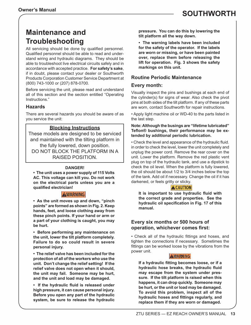
pressure. You can do this by lowering the tilt platform all the way down.• The warning labels have been included for the safety of the operator. If the labels are worn or missing, or have been painted over, replace them before releasing the lift for operation. Fig. 3 shows the safety markings on this unit.
Routine Periodic MaintenanceEvery month:Visually inspect the pins and bushings at each end of the cylinder(s) for signs of wear. Also check the pivot pins at both sides of the tilt platform. If any of these parts are worn, contact Southworth for repair instructions.• Apply light machine oil or WD-40 to the parts listed in the last step.Note: Although the busings are “lifetime lubricated” Teflon® bushings, their performance may be ex-tended by additional periodic lubrication.• Check the level and appearance of the hydraulic fluid. in order to check the level, lower the unit completely and unplug the power cord. Remove the rear cover on the unit. Lower the platform. Remove the red plastic vent plug on top of the hydraulic tank, and use a dipstick to check the oil level. When the platform is fully lowered, the oil should be about 1/2 to 3/4 inches below the top of the tank. Add oil if necessary. Change the oil if it has darkened, or feels gritty or sticky.
CAUTION!It is important to use hydraulic fluid with the correct grade and properties. See the hydraulic oil specification in Fig. 17 of this manual.
Every six months or 500 hours ofoperation, whichever comes first:• Check all of the hydraulic fittings and hoses, and tighten the connections if necessary. Sometimes the fittings can be worked loose by the vibrations from the power unit.
WARNING!If a hydraulic fitting becomes loose, or if a hydraulic hose breaks, the hydraulic fluid may escape from the system under pres-sure. If the tilt platform is raised when this happens, it can drop quickly. Someone may be hurt, or the unit or load may be damaged. To avoid this problem, inspect all of the hydraulic hoses and fittings regularly, and replace them if they are worn or damaged.
Blocking InstructionsThese models are designed to be serviced and maintained with the tilting platform in
the fully lowered, down position. DO NOT BLOCK THE PLATFORM IN A
RAISED POSITION.
DANGER!• The unit uses a power supply of 115 Volts AC. This voltage can kill you. Do not work on the electrical parts unless you are a qualified electrician!
WARNINGS!• As the unit moves up and down, “pinch points” are formed as shown in Fig. 2. Keep hands, feet, and loose clothing away from these pinch points. If your hand or arm or a part of your clothing is caught, you may be hurt.• Before performing any maintenance on the unit, lower the tilt platform completely. Failure to do so could result in severe personal injury.• The relief valve has been included for the protection of all of the workers who use the unit. Don’t change the relief setting! If the relief valve does not open when it should, the unit may fail. Someone may be hurt, and the unit and load may be damaged.• If the hydraulic fluid is released under high pressure, it can cause personal injury. Before you open any part of the hydraulic system, be sure to release the hydraulic

14 ZTU SERIES — EZ REACH OWNER’S MANUAL
ZTU EZ REACH
Repacking the CylinderThe lift in the EZ-Reach unit may use several differ-ent types of cylinders. To order a repacking kit and to receive instructions, please call the Southworth Parts Department at (800) 743-1000 or (207) 878-0700. When ordering, specify the model number and serial number of the unit.
• The clear plastic vent line(s) and the cylinder rod(s) should be free of hydraulic fluid. If you find much fluid in either place, the cylinder seals may be leaking. (It is also possible the tank may be overfilled.) If the worn parts must be replaced, see the section on “Repacking the Cylinder(s).• Disassemble the down valve as shown in Fig. 9. Blow the valve plunger clean with compressed air. Reas-semble the valve and reinstall it.• Drain and discard the hydraulic fluid. The suction filter is in the tank, at the point where the suction line runs out to the pump. Unscrew the hydraulic line, then remove the filter. Blow the filter clean with compressed air. Reinstall the filter in the tank and reassemble the hydraulic line.• Refill the tank with new hydraulic fluid.
CAUTION!If you continue to use fluid after it has “worn out,” the moving parts in the system will wear more quickly.
• Be sure all of the warning labels are in position and legible. The warning labels are intended to protect your workers. If the labels are missing, or if they have been painted over, replace them.
Problem Possible Cause Check ThisTilt Platform will not raise
Battery may need charging Battery volt levelIs the charger putting out 12 volts?Check that 12 volts is being reached at the motor & motor relayIs the charger operating properly?
Load is too heavy Verify the load weightUnit is low on oil Inside the tank, make sure the oil is full to the elbow in the
filler pipe.Tank vent may be plugged. Look to see that the solid plug is not in place of the vent
plug.Suction filter may be clogged. Remove and clean the suction filter.Down valve coil may be ener-gized
Remove the down valve and ensure it is not being ener-gized when the up button is pushed. Check wiring to the down valve.
Unit elevates but will not hold a load
Down valve coil may be ener-gized.
Remove the down valve and ensure it is not being ener-gized when the up button is pushed. Check wiring to the down valve.Ensure debris is not holding the down valve plunger open.
Cylinder may be leaking Check the vent line for signs of oilUnit fails to lower Down valve coil may not be
energizedMake sure the coil is energized when the down button is pushed.Ensure the down valve itself is shifting and allowing oil to go back to the tank (do not remove this under pressure)Check that nothing is binding causing the unit not to lower.
If the steps listed above do not solve the problem, please call the Southworth Products Corp. Customer Service Department at (207) 878-0700.
Troubleshooting

Owner’s Manual SOUTHWORTH
ZTU SERIES — EZ REACH OWNER’S MANUAL 15
TroubleshootingAll servicing should be done by qualified personnel. Qualified personnel should be able to read and understand wiring and hydraulic diagrams. They should be able to troubleshoot live electrical circuits safely and in accordance with accepted practice. For safety’s sake, if in doubt, please contact South-worth Products Corporation at (207) 878-0700.Before servicing the unit, read and understand this entire section and the section entitled “Operating Instructions.”
WARNING!Before performing any maintenance on this unit, lower the tilt platform completely.
CAUTION!If the platform will not raise, do not continue to hold the Up button for more than 2 or 3 seconds. You may damage the pump.
WARNING!Don’t change the setting of the relief valve. If you do change the setting, this may cause a hydraulic part to fail. The tilt platform may drop suddenly. Someone may be hurt, and the unit and load may be damaged. The hydraulic parts in the lift are designed to handle a certain amount of pressure. The relief valve is set to relieve this pressure before it becomes too great. The relief valve has been included for the protection of all of the workers who use the unit.
Ordering Replacement Parts Southworth has carefully chosen the components in your lift to be the best available for the purpose. Replacement parts should be identical to the original equipment. Southworth will not be responsible for equipment failures resulting from the use of incorrect replacement parts or from unauthorized modifications of the machine. Southworth will gladly supply you with replacement parts for your Southworth lift. Key parts are identified in Figures 8 through 15. With your order, please include the model number and the serial number of the lift. You can find these numbers on the name plate, which is located on the crossbar at the base of the cylinder(s). When you are ordering parts for a cylinder, also include the cylinder number. This is stamped on the base of the cylinder housing.
To order replacement parts, please call the Parts Department.Parts are shipped subject to the following terms:
• FOB factory • Returns only with the approval of our parts department.
• Payment net 30 days (except parts covered by warranty). • Freight collect (except parts covered by warranty).
• The warranty for repair parts is 30 days from date of shipment.
Parts replaced under warranty are on a “charge-credit” basis. We will invoice you when we ship the replacement part, then credit you when you return the worn or damaged part, and we verify that it is covered by our warranty. Labor is not covered under warranty for Parts orders.
Parts Department Southworth Products Corp.
Telephone 207) 878-0700 or (800) 743-1000 FAX : (207) 797-4734
[email protected] www.SouthworthProducts.com

16 ZTU SERIES — EZ REACH OWNER’S MANUAL
ZTU EZ REACH
Fig. 9 Down Valve
Valve plunger
Nut
Valve solenoid
Fig. 8 Hydraulic Pump
Pre 8/22/2012 Post 8/22/2012
Owner’s Manual SOUTHWORTH
ZTU SERIES — EZ REACH OWNER’S MANUAL 17
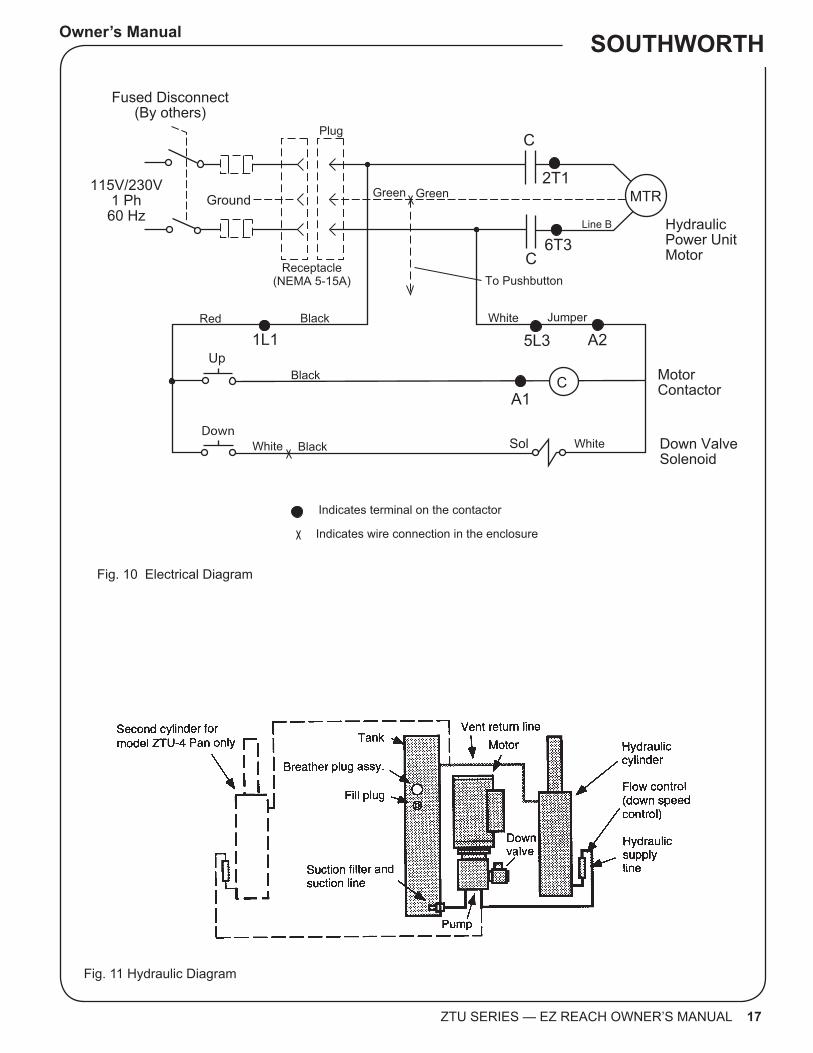
Fig. 10 Electrical Diagram
Fig. 11 Hydraulic Diagram
Ground115V/230V
1 Ph60 Hz
1L1
2T1
6T3
MTR
Hydraulic Power UnitMotor
MotorContactor
Down ValveSolenoid
C
Sol
Up
Down
A1
Fused Disconnect(By others)
C
Line B
GreenGreen
Plug
Receptacle(NEMA 5-15A) To Pushbutton
5L3 A2
White
Black
Black
BlackRed
White
White Jumper
C
Indicates terminal on the contactor
Indicates wire connection in the enclosure J130

18 ZTU SERIES — EZ REACH OWNER’S MANUAL
ZTU EZ REACH
Fig. 12. Parts Identification - Side ViewModels ZTU-2, ZTU-4

Owner’s Manual SOUTHWORTH
ZTU SERIES — EZ REACH OWNER’S MANUAL 19
Fig. 13. Parts Identification - Base of unit (viewed from front) Models ZTU-2, ZTU-4, ZTU-2 Pan
Fig. 14. Parts Identification - Base of unit (viewed from front) Models ZTU-4 Pan

20 ZTU SERIES — EZ REACH OWNER’S MANUAL
ZTU EZ REACH
Southworth Products Corp warrants this product to be free from defects in material or workmanship for a period of 2 years of single shift usage from date of shipment, providing claim is made in writing within that time period. This warranty shall not cover modified designs for special applications, failure or defective operation caused by misuse, misapplication, negligence or accident, exceeding recommended capacities, failure to perform required maintenance or altering or repairing, unless alteration is authorized by Southworth Products Corp. Except as set forth herein, there are no other warranties, express or implied, including the warranties of merchantability and fitness for a particular purpose, all of which are hereby excluded.
Southworth Products Corp makes no warranty or representation with respect to the compliance of any product with state or local safety or product standard codes, and any failure to comply with such codes shall not be considered a defect of material or workmanship under this warranty. Southworth Products Corp shall not be liable for any direct or consequential damages arising out of such noncompliance.
Southworth Products Corp’s obligation under this warranty is limited to the replacement or repair of defective components at its factory or another loca-tion at Southworth Products Corp’s discretion. The Southworth Warranty is for product sold with in North America. For products shipped outside of North America the warranty will be for replacement of defective parts only. Labor is not included. This is buyer’s sole remedy. Except as stated herein, Southworth Products Corp will not be liable for any loss, injury or damage to persons or property, nor for direct, indirect, or consequential damage of any kind, resulting from failure or defective operation of said product.
This warranty may be altered only in writing by Southworth Products Corp, Portland, Maine.
SOUTHWORTH PRODUCTS CORPP.O. Box 1380, Portland, ME 04104-1380Telephone: (800) 743-1000 • (207) 878-0700Fax: (207) 797-4734www.SouthworthProducts.com
2 YEAR WARRANTY

For more information, contact Southworth Products Telephone (800) 743-1000 Fax (207) 797-4734
Email: [email protected]
Southworth is the world class supplier of products designed to improve productivity and enhance safety. Our staff has over 400 years of engineering experience. If one of our standard products does not meet your needs, our engineers can custom design equipment specifically suited to your material handling application. Spring PalletPal Load Leveler Lift with Flush Mount Turntable Portable Container Tilters
Roll on Level Loaders Portable Lifts Floor to Mezzanine Lifts Stack‐n‐Go Powered Stacker
Pallet Rotators
Dock Lifts
Floor Height LiftsRoll‐E