Embed Size (px)
Citation preview
1
LISTED AND TESTED BASED ON UL 1081
FOR USE WITH SWIMMING POOLS AND SPAS
Owner’s Manual for “P” Series Variable Speed Pumps
IMPORTANT SAFETY INSTRUCTIONS
READ AND FOLLOW ALL INSTRUCTIONS
Table of Contents SECTION 1 - SAFETY INSTRUCTIONS........................................................ .......................................................... 2
SECTION 2 - INSTALLATION.................................................................................................................................... 3
SECTION 3 - MAINTENANCE ..................................................................................................................................14
SECTION 4 - RESTART INSTRUCTIONS .............................................................................................................. 17
SECTION 5 - TROUBLESHOOTING........................................................................................................................18
SECTION 6 - TECHNICAL DATA ............................................................................................................................19
This manual contains important information about the installation, operation and safe use of this product. This information should be given to the owner/operator of this equipment.
RISK OF ELECTRICAL SHOCK OR ELECTROCUTION This pool pump must be installed by a licensed or certified electrician or a qualified pool installer in accordance with the latest edition of the National Electrical Code, NFPA 70 (“NEC”) and/or all applicable local and state codes and ordinances. Installations in Canada must be in accordance with the latest edition of CSA C22.1 - the Canadian Electric Code, part 1 (“CEC”).
Improper installation could cause an electrical hazard which may result in death or serious injury to pool users, installers, or others due to electrical shock, and/or property damage. Always disconnect power to the pool pump at the circuit breaker before servicing the pump. Failure to do so could result in death or serious injury to pool users, installers or others. To reduce the risk of injury, do not permit children to use this product unless they are closely supervised at all times.
.
Fluidra USA, LLC 8525 Mallory Road Jacksonville, FL 32220 Phone (904) 378-0999 Fax (904) 378-0488
SAVE THESE INSTRUCTIONS
WARNING: Before installing this product, read and follow all warning notices and instructions accompanying this pump. Failure to follow safety warnings and instructions can result in severe injury, death, or property damage. Call (904) 378-0999 for additional free copies of these instructions.
CAUTION: This pump is for use with permanently installed pools and may also be used with hot tubs and spas if so marked. Do not use with storable pools, do not install within an outer enclosure or beneath the skirt of a hot tub or spa unless so marked
2
GENERAL
The Viron “P” Series Pool Pumps feature a unique variable-speed permanent magnet DC motor combined with an energy efficient pump wet end. When installed and plumbed correctly, the Viron “P” series pumps will significantly reduce operating costs, lower noise levels and reduce greenhouse emissions. The Viron “P” Series Pool Pump range are available in a variety of models, with the following factory set speeds (High, Medium and Low) which offer approximate flow rates: of 35 GPM up to 145 GPM @ 27 FT Each speed can be easily changed to suit your pool size, filter, plumbing and application. The Viron “P” Series pumps must be installed by a qualified pool professional.
FEATURES - Continuous duty rated motor - Precision reinforced molded high head impeller, giving extra performance - Single piece molded body for added strength and longer life - Rapid priming diffuser quickly corrects loss of water flow - Quick and easy disassembly for servicing - Large capacity basket with easily removed ramp on lid - Ability to adjust factory pre-set speeds for optimum water flow and maximum energy savings for your pool and its
equipment.
SECTION 1. SAFETY INSTRUCTIONS
GENERAL When you receive the pump, check the carton for damage. Open the carton and check the pump for concealed damage, such as cracks, dents, or a bent base. If you find damage, contact the shipper or the distributor where the pump was purchased.
The pump must be placed on a solid foundation that will not vibrate and AstralPool recommends bolting the pump to the foundation and providing adequate drainage should any leaks develop.
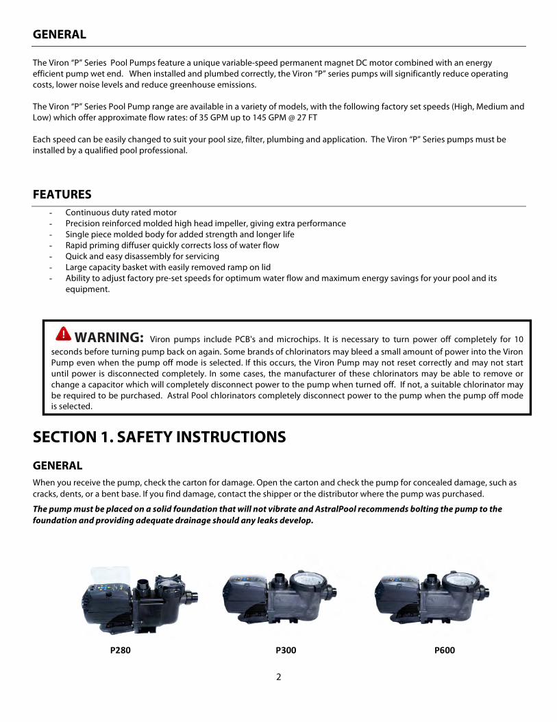
P280 P300 P600
WARNING: Viron pumps include PCB's and microchips. It is necessary to turn power off completely for 10 seconds before turning pump back on again. Some brands of chlorinators may bleed a small amount of power into the Viron Pump even when the pump off mode is selected. If this occurs, the Viron Pump may not reset correctly and may not start until power is disconnected completely. In some cases, the manufacturer of these chlorinators may be able to remove or change a capacitor which will completely disconnect power to the pump when turned off. If not, a suitable chlorinator may be required to be purchased. Astral Pool chlorinators completely disconnect power to the pump when the pump off mode is selected.
3
ELECTRICAL All electrical work must be performed by a licensed electrician and conform to all national, state, and local codes. When installing and using this electrical equipment, basic safety precautions should always be followed, including the following:
The correct voltage and frequency as specified on the pump data plate is necessary for proper performance and long motor life. Make sure that the wiring specification meets or exceeds the motor requirements (230v or 115v), see the following for
recommendations.
1. When in doubt, use a heavier gauge (larger diameter) wire which helps the motor to run cooler and more efficiently. 2. Make sure all electrical connections are clean and tight. 3. Cut wires to the appropriate length so they don’t overlap or touch when connected to the terminal board, and
insulate all connections carefully to prevent grounding or short circuits. 4. Permanently ground the motor using the green ground terminal located on the inside of the motor canopy, under
access plate. 5. Use the correct wire size and type specified by National Electrical Code, “NEC” (or Canadian Electric Code, “CEC”, for
Canada). Make sure the ground wire is connected to an electrical service ground. 6. Electrically bond the motor to the pool structure in accordance with the National Electrical Code (or Canadian Electric
Code for Canada). Use a solid No. 8 AWG or larger copper conductor. 7. Additionally, run a wire from the external bonding point to the pool bonding structure following the NEC/CEC. 8. Connect the pump to a permanent/dedicated circuit. Make sure no other lights or appliances are on the same circuit.
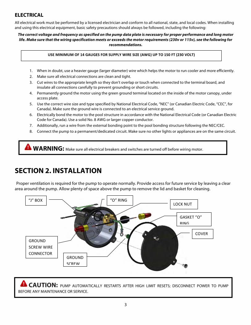
SECTION 2. INSTALLATION Proper ventilation is required for the pump to operate normally. Provide access for future service by leaving a clear area around the pump. Allow plenty of space above the pump to remove the lid and basket for cleaning.
WARNING: Make sure all electrical breakers and switches are turned off before wiring motor.
CAUTION: PUMP AUTOMATICALLY RESTARTS AFTER HIGH LIMIT RESETS; DISCONNECT POWER TO PUMP BEFORE ANY MAINTENANCE OR SERVICE.
USE MINIMUM OF 14 GAUGES FOR SUPPLY WIRE SIZE (AWG) UP TO 150 FT (230 VOLT)
GASKET “O” RING
COVER
“O” RING
GROUND SCREW
LOCK NUT “J” BOX
GROUND SCREW WIRE CONNECTOR
4
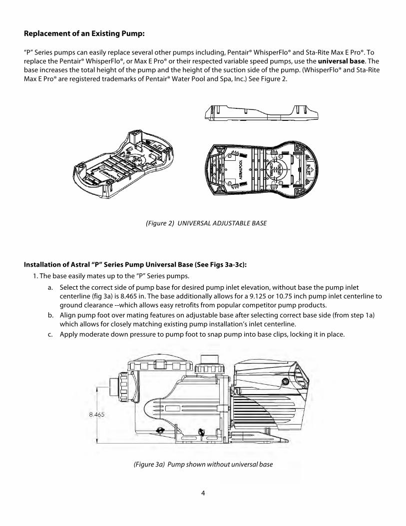
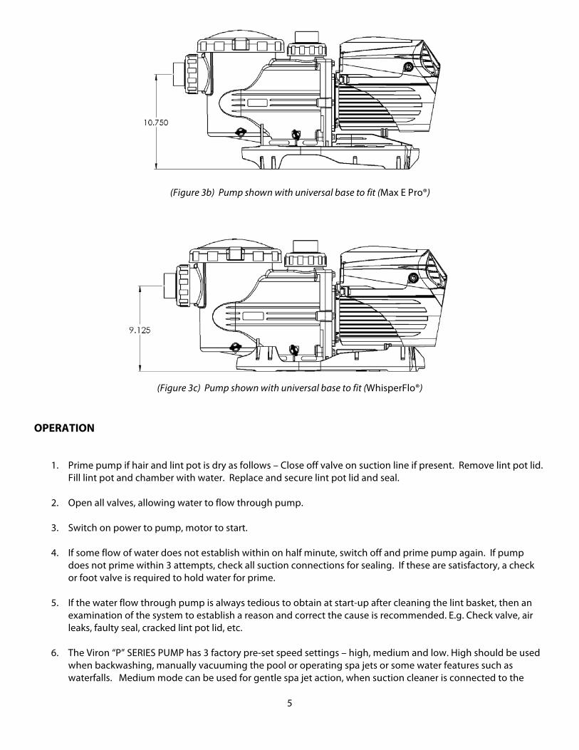
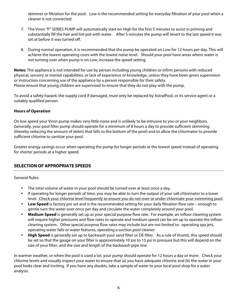
Replacement of an Existing Pump: “P” Series pumps can easily replace several other pumps including, Pentair® WhisperFlo® and Sta-Rite Max E Pro®. To replace the Pentair® WhisperFlo®, or Max E Pro® or their respected variable speed pumps, use the universal base. The base increases the total height of the pump and the height of the suction side of the pump. (WhisperFlo® and Sta-Rite Max E Pro® are registered trademarks of Pentair® Water Pool and Spa, Inc.) See Figure 2.
Installation of Astral “P” Series Pump Universal Base (See Figs 3a-3c):
1. The base easily mates up to the “P” Series pumps.
a. Select the correct side of pump base for desired pump inlet elevation, without base the pump inlet centerline (fig 3a) is 8.465 in. The base additionally allows for a 9.125 or 10.75 inch pump inlet centerline to ground clearance --which allows easy retrofits from popular competitor pump products.
b. Align pump foot over mating features on adjustable base after selecting correct base side (from step 1a) which allows for closely matching existing pump installation’s inlet centerline.
c. Apply moderate down pressure to pump foot to snap pump into base clips, locking it in place.
(Figure 3a) Pump shown without universal base
(Figure 2) UNIVERSAL ADJUSTABLE BASE
5
(Figure 3c) Pump shown with universal base to fit (WhisperFlo®) OPERATION
1. Prime pump if hair and lint pot is dry as follows – Close off valve on suction line if present. Remove lint pot lid. Fill lint pot and chamber with water. Replace and secure lint pot lid and seal.
2. Open all valves, allowing water to flow through pump.
3. Switch on power to pump, motor to start.
4. If some flow of water does not establish within on half minute, switch off and prime pump again. If pump
does not prime within 3 attempts, check all suction connections for sealing. If these are satisfactory, a check or foot valve is required to hold water for prime.
5. If the water flow through pump is always tedious to obtain at start-up after cleaning the lint basket, then an
examination of the system to establish a reason and correct the cause is recommended. E.g. Check valve, air leaks, faulty seal, cracked lint pot lid, etc.
6. The Viron “P” SERIES PUMP has 3 factory pre-set speed settings – high, medium and low. High should be used
when backwashing, manually vacuuming the pool or operating spa jets or some water features such as waterfalls. Medium mode can be used for gentle spa jet action, when suction cleaner is connected to the
(Figure 3b) Pump shown with universal base to fit (Max E Pro®)
6
skimmer or filtration for the pool. Low is the recommended setting for everyday filtration of your pool when a cleaner is not connected.
7. The Viron “P” SERIES PUMP will automatically start on High for the first 5 minutes to assist in priming and
substantially fill the hair and lint pot with water. After 5 minutes the pump will revert to the last speed it was set at before it was turned off.
8. During normal operation, it is recommended that the pump be operated on Low for 12 hours per day. This will
achieve the lowest operating costs with the lowest noise level. Should your pool have areas where water is not turning over when pump is on Low, increase the speed setting.
Notes: The appliance is not intended for use by person including young children or infirm persons with reduced physical, sensory or mental capabilities, or lack of experience or knowledge, unless they have been given supervision or instruction concerning use of the appliance by a person responsible for their safety. Please ensure that young children are supervised to ensure that they do not play with the pump. To avoid a safety hazard, the supply cord if damaged, must only be replaced by AstralPool, or its service agent or a suitably qualified person. Hours of Operation On low speed your Viron pump makes very little noise and is unlikely to be intrusive to you or your neighbors. Generally, your pool filter pump should operate for a minimum of 8 hours a day to provide sufficient skimming (thereby reducing the amount of debris that falls to the bottom of the pool) and to allow the chlorinator to provide sufficient chlorine to sanitize your pool. Greater energy savings occur when operating the pump for longer periods at the lowest speed instead of operating for shorter periods at a higher speed.
SELECTION OF APPROPRIATE SPEEDS
General Rules:
• The total volume of water in your pool should be turned over at least once a day. • If operating for longer periods of time, you may be able to turn the output of your salt chlorinator to a lower
level. Check your chlorine level frequently to ensure you do not over or under chlorinate your swimming pool. • Low Speed is factory pre set and is the recommended setting for your daily filtration flow rate – enough to
gentle turn the water over once per day and circulate the water completely around your pool. • Medium Speed is generally set up as your special purpose flow rate. For example, an infloor cleaning system
will require higher pressures and flow rates to operate and medium speed can be set up to operate the infloor cleaning system. Other special purpose flow rates may include but are not limited to: operating spa jets, operating water falls or water features, operating a suction pool cleaner.
• High Speed is generally set up to backwash your sand filter or DE filter. As a rule of thumb, this speed should be set so that the gauge on your filter is approximately 10 psi to 15 psi in pressure but this will depend on the size of your filter, and the size and length of the backwash pipe line.
In warmer weather, or when the pool is used a lot, your pump should operate for 12 hours a day or more. Check your chlorine levels and visually inspect your water to ensure that (a) you have adequate chlorine and (b) the water in your pool looks clear and inviting. If you have any doubts, take a sample of water to your local pool shop for a water analysis.
7
Some Tips: The P280 and P300 will provide more than 2000 gallons per hour depending on piping, valves, filter size and other equipment installed on your pool, Low speed will use approximately 10% of the power consumption that high speed will use. Therefore, operating the pump 8 hours per day will provide a 18,000 gallons pool one complete turn over. The P600 pump will provide around 9500 Gallons per hour on high speed, depending on pipe work and the Factory preset low speed at 1125 RPM will provide around 3200 Gallons per minute. This is sufficient to turn a 25000 Gallons pool over once per day. As a guide, low speed should achieve a visible skimming of the surface of the pool through your skimmer box. When connected to an AstralPool compatible salt chlorinator, Viron Connect Touch Screen Control System, we recommend that for one hour a day the filtration period is operated on at least medium speed to achieve full circulation and good surface skimmer of the pool. The balance of the filtration cycle can then be set on low speed. However, should your pool water develop cloudiness or your pool surface exhibit algae growth you may need to increase the low speed of your pump to ensure adequate circulation of water and chlorine to all parts of your pool. It is important to check your chlorine levels, pH and other parameters to ensure your water quality is correct before adjusting the speed of your pump. We recommend these checks are carried out by your professional pool shop or service technician.
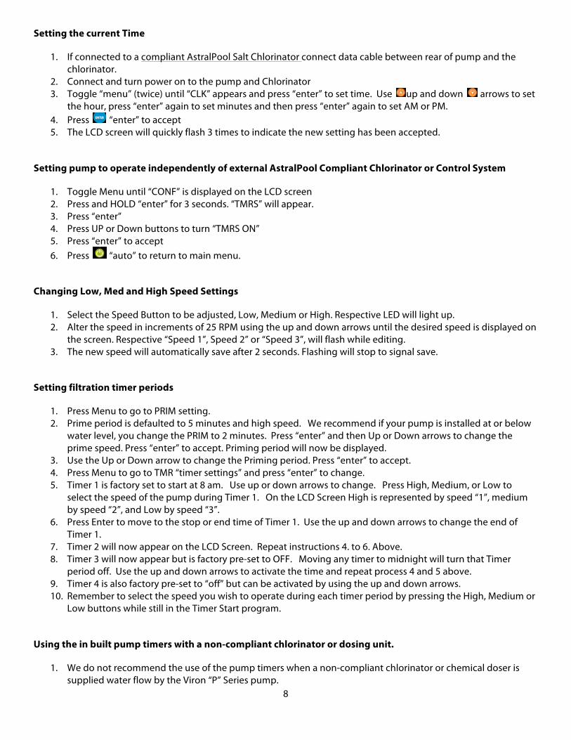
OPERATION OF CONTROL PANEL – VIRON P280, P300 AND P600
The Viron P280, P300 and P600 incorporates an LCD backlit screen with the following features:
Built-in time clock:
• Programmable for up to four timer periods each day • Timer periods can be disused and 1, 2, 3, or 4 periods selected • Different speed (low, medium, high) for each timer period • Displays actual RPM of motor and low, medium and high speed can be adjusted to suit
your pool • Time clock and timer periods can be disabled if connected to an external time clock • Can be programmed by a compatible AstralPool remote control or chlorinator to
operate at different speeds during different times of the day • Enables the priming (start up) speed to be adjustable and the time of the start up speed
to be changed from 2 minutes up to 120 minutes
OPERATION OF CONTROL PANEL – VIRON P280, P300 AND P600
Using the built-in timer to operate pump with an AstralPool Chlorinator unit
Factory Default Setting
1. The inbuilt timers are activated and will control the time the pump operates 2. Connectivity to AstralPool compliant Salt Chlorinators, or Viron Connect remote Controls is turned “off” 3. Use the “auto” button to turn the pump on or off. When in on position, the pump will remain off until the
next timer period unless pressed again to manually on. If pump is turned to manually on, it will continue to operate indefinitely. If in the “Off” position (visible on the LCD), the pump will remain indefinitely off. For timer operation, ensure the “auto” button is pressed so that the LCD screen displays “auto”.
0000
0000
8
Setting the current Time
1. If connected to a compliant AstralPool Salt Chlorinator connect data cable between rear of pump and the chlorinator.
2. Connect and turn power on to the pump and Chlorinator 3. Toggle “menu” (twice) until “CLK” appears and press “enter” to set time. Use up and down arrows to set
the hour, press “enter” again to set minutes and then press “enter” again to set AM or PM. 4. Press “enter” to accept 5. The LCD screen will quickly flash 3 times to indicate the new setting has been accepted.
Setting pump to operate independently of external AstralPool Compliant Chlorinator or Control System
1. Toggle Menu until “CONF” is displayed on the LCD screen 2. Press and HOLD “enter” for 3 seconds. “TMRS” will appear. 3. Press “enter” 4. Press UP or Down buttons to turn “TMRS ON” 5. Press “enter” to accept 6. Press “auto” to return to main menu.
Changing Low, Med and High Speed Settings
1. Select the Speed Button to be adjusted, Low, Medium or High. Respective LED will light up. 2. Alter the speed in increments of 25 RPM using the up and down arrows until the desired speed is displayed on
the screen. Respective “Speed 1”, Speed 2” or “Speed 3”, will flash while editing. 3. The new speed will automatically save after 2 seconds. Flashing will stop to signal save.
Setting filtration timer periods
1. Press Menu to go to PRIM setting. 2. Prime period is defaulted to 5 minutes and high speed. We recommend if your pump is installed at or below
water level, you change the PRIM to 2 minutes. Press “enter” and then Up or Down arrows to change the prime speed. Press “enter” to accept. Priming period will now be displayed.
3. Use the Up or Down arrow to change the Priming period. Press “enter” to accept. 4. Press Menu to go to TMR “timer settings” and press “enter” to change. 5. Timer 1 is factory set to start at 8 am. Use up or down arrows to change. Press High, Medium, or Low to
select the speed of the pump during Timer 1. On the LCD Screen High is represented by speed “1”, medium by speed “2”, and Low by speed “3”.
6. Press Enter to move to the stop or end time of Timer 1. Use the up and down arrows to change the end of Timer 1.
7. Timer 2 will now appear on the LCD Screen. Repeat instructions 4. to 6. Above. 8. Timer 3 will now appear but is factory pre-set to OFF. Moving any timer to midnight will turn that Timer
period off. Use the up and down arrows to activate the time and repeat process 4 and 5 above. 9. Timer 4 is also factory pre-set to “off” but can be activated by using the up and down arrows. 10. Remember to select the speed you wish to operate during each timer period by pressing the High, Medium or
Low buttons while still in the Timer Start program.
Using the in built pump timers with a non-compliant chlorinator or dosing unit.
1. We do not recommend the use of the pump timers when a non-compliant chlorinator or chemical doser is supplied water flow by the Viron “P” Series pump.
9
2. In this case, the pump operating hours should be controlled by the chlorinator time clock and the pump plugged into the chlorinator. This is a safety measure provided for by most chlorinator manufacturers.
3. However, it is important to deactivate the inbuilt pump timers. 4. Toggle Menu until “CONF” is displayed on the LCD screen 5. Press and HOLD “enter” for 3 seconds 6. Toggle Menu until “TMR” appears. 7. Press UP or Down buttons to turn “TMR OFF” 8. Press “enter” to accept 9. Press “auto” to return to main menu. 10. When cycling through the Menu button TMR will no longer appear 11. You will no longer be able to automatically have the speed of the pump changed during different times of the
day. 12. However, if you wish for a period where the pump operates at a high speed, for example to circulate the water
vigorously for a part of the daily filtration, you can use the PRIMING setting to do so.
Using the PRIMING program to circulate the water at a higher flow rate for part of the daily filtration cycle.
1. Toggle Menu to go to PRIM setting. 2. Prime period is defaulted to 5 minutes and high speed. Use the up and down arrows to change the Priming
period up to 120 minutes. Use the High, medium, or low buttons to select the speed you wish the pump to operate for during the Priming period. In this case, we recommend the High Speed button be selected.
3. Press “Auto” to exit the programming.
Using Pump with AstralPool compliant external control AstralPool manufactures Salt Chlorinators, or the Viron Connect Touch Screen Control system which can control both the operating times of the all Viron “P” Series Pump pumps (P280, P300 and P600) PLUS the speed the pump operates at during each timer period.
For the P600 you must enable the communication port and disable the Pump in built timers.
1. Toggle Menu until CONF (configure) appears. Hold enter for 3 seconds. 2. Toggle Menu until “TMR” appears. 3. Press UP or Down buttons to turn “TMR OFF”. Remember, you are now using the external control to set the
pump operating hours, so the pump timer must be turned off. 4. Press “enter” to accept 5. Toggle menu until SYS (system) appears. Press the up or down button and turn to “ON”. The Viron P600
“P” Series Pump will accept the start, end and pump speed instructions from the AstralPool compliant control chlorinator Rolachem dosing controller or Viron Connect Touch Screen Control.
6. Press “auto” to return to main menu. 7. The time will still be visible on the LCD display however, the timer function in the menu setting will no longer
appear. Toggling the menu button will now only display PRIM (priming program), CLK (clock setting) and CONF (Configuration menu).
8. Refer to your AstralPool compliant Chlorinator, RolaChem Dosing Control or Viron Connect Touch Screen Control manual for details of programming the pump speed and operating hours.
10
Fault Codes
Fault Code (displayed on screen)
Meaning
HI T Over Temperature
HI A Over Current
Lo V* Under Input Voltage
BSUC Motor is Stuck
*Please note: It is normal for the “Lo V” fault code to display briefly on start up.
Data cable connector:
If a compatible AstralPool VX Salt Chlorinator, Viron Salt Chlorinator or Viron Connect Touch Screen, is connected with the AstralPool communication cable, the speed of the pump and operating hours can be controlled by these devices.
The Viron P280, P300 and P600 Pump must have its inbuilt timer deactivated if the pump operating times and speeds are to be operated by the compatible AstralPool Salt Chlorinator or Viron Connect remote touch screen. Remove 2 philips head screens from rear of pump and the data port cover is removed by hand. Plug RJ12 6 wire flat cable purchased from AstralPool into rear of pump and reassemble. To achieve a proper seal, press the flat cable under the guide tabs (detailed view A). Slide data port cover back on by aligning the tabs with the slots and the flat cable with the recess (detailed view B).
11
REMOTE CONTROL OF SPEEDS AND TIMER FUNCTIONS
Viron P280, P300 and P600 pump stand alone • 4 built in timer periods in pump • 3 programmable speed settings • Low, medium or high speed can be selected in each timer period • Priming period can be selected from 2 to 120 minutes • Prime RPM can be selected from 1425 to 3540 RPM (on P280 and P300 pumps, the max prime speed is 3075 RPM)
All model Viron “P” Series pumps and compatible VX Timer model chlorinator or Viron Salt Chlorinator • Timer periods set up in chlorinator • Low, medium or high speed can be selected for each timer period • Data cable connecting pump to chlorinator via comms interface module • P600 Pump to be set up with timer periods deactivated
POWER INPUT
230v power 24v comms data
12
SPEED SELECTION EXAMPLES FOR VIRON P280, P300 AND P600
Function Speed Vacuuming Pool or Spa Medium Speed (high speed may collapse vacuum hose) Operating Spa Jets Medium or High Speed Operating Waterfall or Water Feature Medium Speed or High Speed, depending on effect
required Cleaning up pool with Cloudy Water Up to 24 hours on High Speed General Filtration Low Speed (8 hours in winter, 8 to 12 hours in summer) Single Pump Infloor Cleaning System Medium Speed for 3 hours per day and low speed for 5 or 6
hours per day Compatible Pressure Cleaner 2 or 3 hours per day on high speed, 5 or 6 hours per day on
low speed
230v power 24v data
POWER SUPPLY TRANSFORMER
All model Viron “P” Series pumps, VX S (non timer) model chlorinator and Viron Connect Remote Control System
• Timer periods set up in controller • 3 programmable speed settings on pump • Select low, medium or high speed during each timer period • Data cables connecting pump/chlorinator/controller • P280, P300 and P600 Pump to be set up with timer periods deactivated • Pump speed can be changed from pump or controller
230v power 24v data
POWER INPUT
13
USE WITH SUCTION CLEANERS
When connecting a suction cleaner to the Viron “P” SERIES PUMP, pump it essential that full prime is achieved on the pump prior to connecting the cleaner hose. During operation at low speeds, the Viron "P" SERIES PUMP may only operate with partial prime in the hair and lint pot chamber.
To operate a suction cleaner on your pump:
1. Choose the speed button (low, medium or high) on which the pump will operate when the suction cleaner is connected. 2. Allow pump to operate for a minimum of 2 minutes to allow a full prime to be achieved. 3. Connect cleaner plate and hose to skimmer/wall suction only after all air has been purged from the top of the hair and
lint pot of your Viron Pump. 4. Adjust speed (with increase or decrease buttons) at which the cleaner will travel to all areas of the pool. Factory set
medium speed will usually operate all suction cleaner types in most pools. If using the Low Speed setting, it will usually be necessary to increase the low speed to ensure the suction cleaner operates reliably.
5. When cleaner is no longer required, disconnect and remove hose/cleaner plate from system. Select the lowest filtration speed that keeps your pool clean.
6. If replacing or selecting a new cleaner, AstralPool recommends a robotic cleaner which operates independently from the filter pump and allows the pump to operate at a speed which offers the maximum energy (and cost) savings.
USE WITH ASTRALPOOL GAS HEATERS
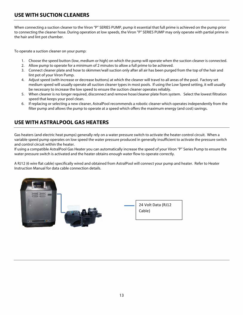
Gas heaters (and electric heat pumps) generally rely on a water pressure switch to activate the heater control circuit. When a variable speed pump operates on low speed the water pressure produced in generally insufficient to activate the pressure switch and control circuit within the heater. If using a compatible AstralPool Gas Heater you can automatically increase the speed of your Viron “P” Series Pump to ensure the water pressure switch is activated and the heater obtains enough water flow to operate correctly. A RJ12 (6 wire flat cable) specifically wired and obtained from AstralPool will connect your pump and heater. Refer to Heater Instruction Manual for data cable connection details.
24 Volt Data (RJ12 Cable)
14
SECTION 3. MAINTENANCE THIS FILTER OPERATES UNDER HIGH PRESSURE When any part of the circulating system (e.g., lock ring, pump, filter, valves, etc.) is serviced, air can enter the system and become pressurized. Pressurized air can cause the lid to blow off which can result in severe injury, death or property damage. To avoid this potential hazard, follow these instructions carefully.
WARNING DO NOT open the strainer pot if pump fails to prime, or if pump has been operating without water in the strainer pot. Pumps operated in these circumstances may experience a buildup of vapor pressure and may contain scalding hot water. Opening the pump may cause serious personal injury. In order to avoid the possibility of personal injury, make sure the suction and discharge valves are open and strainer pot temperature is cool to touch, then open with extreme caution.
CAUTION: To prevent damage to the pump and filter and for proper operation of the system, clean pump strainer and skimmer baskets regularly.
15
THE PUMP STRAINER BASKET The Pump Strainer Basket, sometimes referred as the “hair and lint pot,” is the unit in front of the volute. Inside the chamber is the basket which must be kept clean of leaves and debris at all times. View the basket through the ‘See Through Lid’ to inspect for leaves. Regardless of the length of time between filter cleaning, it is most important to visually inspect the hair and lint pot basket at least once a week. A dirty basket will reduce the efficiency of the filter and heater and also put an abnormal stress on the pump motor which could result in a costly repair bill. PUMP STRAINER BASKET CLEANING PROCEDURE
1. Turn the power “OFF” at the house circuit breaker. 2. Turn off motor. 3. Relieve pressure in the system by allowing the water to cool. 4. Gently tap the clamp in a counter-clockwise direction to remove the clamp and lid. 5. Put the debris from the basket into the trash and rinse out the basket. If the basket is cracked, it should be
replaced. 6. Replace the basket and fill the pump pot and volute up to the inlet port with water. 7. Clean the cover, cover O-ring, and sealing surface of the pump pot. Grease the O-ring with Teflon or silicone
grease. NEVER USE PETROLEUM BASED GREASE AS THEY DEGRADE THE O-RINGS. 8. Reinstall the lid by placing the clamp and the lid on the pot; see Exploded View (pg 12) for reference. Make
sure the lid O-ring is properly placed. Seat the clamp and lid then turn clockwise until the handles are perpendicular to the inlet/outlet ports.
9. Turn the power “ON” at the house circuit breaker. Reset the pool timer clock to the correct time. 10. Open the High Flow manual air relief valve on top of the filter. 11. Start the pump, while standing clear from the filter 12. Bleed air from the filter until a steady stream of water comes out. Close the High Flow manual air relief valve.
WINTERIZING
1. If the air temperature drops below 35° F., the water in the pump can freeze and cause damage. Freeze damage is not warrantable.
2. To prevent freeze damage follow the procedures listed below: a. Shut off electrical power for the pump at the house circuit breaker. b. Drain the water out of the pump case by removing the two thumb-twist drain plugs from the case.
Store the plugs in the pump basket to prevent losing them. c. Cover the motor to protect it from severe rain, snow and ice.
CARE OF THE ELECTRIC MOTOR
1. Protect motor from excess heat a. Shade the motor from the sun b. Any enclosure must be well ventilated to prevent overheating c. Provide ample cross ventilation
2. Protect motor from excess dirt and debris a. Protect from any foreign matter or splashing water b. Do not store (or spill) pool chemicals near the motor c. Avoid sweeping or stirring up dust near the motor while it is operating d. If a motor has been damaged by dirt it voids the motor warranty
16
3. Protect motor against excess moisture a. Protect from splashing pool water b. Protect from the weather c. Protect from lawn sprinklers d. If a motor has become wet - let it dry before operating Do not allow the pump to operate if it has been flooded e. If a motor has been damaged by water it voids the motor warranty
NOTE: DO NOT wrap motor with plastic or other airtight materials. The motor may be covered during a storm, or for winter storage, etc., but never when operating, or expecting operation. NOTE: When replacing the motor, be certain that the motor support is correctly positioned to support the size of motor being installed.
PUMP DISASSEMBLY
1. All moving parts are located in the rear sub-assembly of this pump. Tools required: a. 3/16 inch Allen head wrench. b. 1/2 inch open end wrench. c. 1/2 inch open end wrench or socket. d. Flat blade screwdriver or ¼ inch nut driver to remove motor cap. e. Phillips screwdriver
2. To remove and repair the motor sub-assembly perform the following procedures. a. Turn off the pump circuit breaker at the main panel. b. Drain the pump by removing the drain plugs. c. Remove the 6 bolts that hold the main pump body (strainer pot/volute) to the rear sub-assembly. d. GENTLY pull the two pump halves apart, removing the rear sub-assembly. e. Use a Phillips head screwdriver to loosen the two holding screws located on the diffuser. f. Place a flat head screwdriver through the hole located at the center of the plastic fan cowl and hold
the shaft secure with the groove at the end of the shaft. g. Hold the impeller securely in place and remove the impeller lock screw by using a 3/16 inch Allen
head wrench. The screw is a left-handed thread and loosens in a clockwise direction. h. To unscrew the impeller from the shaft, twist the impeller counter-clock wise. i. Remove the four bolts from the seal plate to the motor, using a 1/2 inch wrench. j. If replacing the mechanical seal set, see Sect. B. “Pump Reassembly/Seal Replacement” on next page.
PUMP REASSEMBLY AND SEAL REPLACEMENT
1. When installing the replacement shaft seal, use a light density soap and water to seal the seal. Press the seal into the seal plate with your thumbs and wipe off the ceramic and carbon faces with a clean cloth, and ensure the seal is fully seated. See Figure 4.
WARNING DO NOT open the strainer pot if pump fails to prime, or if pump has been operating without water in the strainer pot. Pumps operated in these circumstances may experience a buildup of vapor pressure and may contain scalding hot water. Opening the pump may cause serious personal injury. In order to avoid the possibility of personal injury, make sure the suction and discharge valves are open and strainer pot temperature is cool to touch, then open with extreme caution.
17
2. Before installing the ceramic section of the seal into the impeller, be sure the impeller is clean. Use a light density soap and water to seal the seal. Press the seal into the impeller with your thumbs and wipe off the ceramic and carbon faces with a clean cloth.
3. Remount the seal plate to the motor by installing bolts in an X pattern while tightening them. 4. Clean the motor shaft thread and the impeller insert, then screw the impeller onto the motor shaft. 5. Screw in the impeller lock screw (counter-clockwise and tighten while holding the motor shaft with flat head
screwdriver). 6. Remount the diffuser onto the seal plate. Make sure the plastic pins and holding screw inserts are aligned. 7. Grease (with a non petroleum-based grease) the diffuser O-ring and seal plate gasket using silicon grease.
NEVER USE PETROLEUM BASED GREASE AS IT DEGRADES O-RINGS AND SEALS.
8. Grease (with a non petroleum-based grease) the bolt threads. Assemble the motor sub-assembly to the strainer pot pump body by using the two through bolts for proper alignment. Do not tighten the through bolts until all 6 bolts are in place and finger tightened first. When tightening, alternate torqueing of bolts using an X-pattern to maintain even tightening.
9. Fill the pump with water.
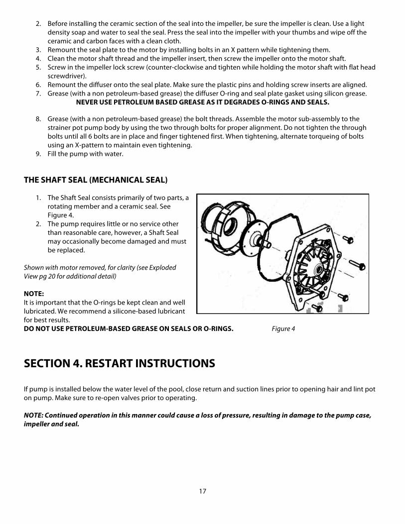
THE SHAFT SEAL (MECHANICAL SEAL)
1. The Shaft Seal consists primarily of two parts, a rotating member and a ceramic seal. See Figure 4.
2. The pump requires little or no service other than reasonable care, however, a Shaft Seal may occasionally become damaged and must be replaced.
Shown with motor removed, for clarity (see Exploded View pg 20 for additional detail) NOTE: It is important that the O-rings be kept clean and well lubricated. We recommend a silicone-based lubricant for best results. DO NOT USE PETROLEUM-BASED GREASE ON SEALS OR O-RINGS. Figure 4
SECTION 4. RESTART INSTRUCTIONS If pump is installed below the water level of the pool, close return and suction lines prior to opening hair and lint pot on pump. Make sure to re-open valves prior to operating. NOTE: Continued operation in this manner could cause a loss of pressure, resulting in damage to the pump case, impeller and seal.
18
PRIMING THE PUMP NOTE: The pump strainer pot must be filled with water before the pump is initially started. Follow these steps to prime the pump:
1. Remove the pump lid. 2. Fill the pump strainer pot with water. 3. Reassemble the pump cover and plastic clamp onto the strainer pot. The pump is now ready to prime. 4. Open the air release valve on the filter, and stand clear of the filter. 5. Turn on the switch or time clock. 6. When water comes out of the air release valve of the filter, close the valve. The system should now be free of
air and recirculating water to and from the pool.
SECTION 5. TROUBLESHOOTING
FAILURE TO PUMP Pump will not prime - too much air. Remedy:
1. Check suction piping and valve glands on any suction gate valves 2. Secure lid on pump strainer pot and make sure lid gasket is in place 3. Check water level to make sure skimmer is not drawing air
Pump will not prime - not enough water. Remedy:
1. Make sure suction lines, pump strainer, and pump volute are full of water 2. Make sure valve on suction line is working and open, (some systems do not have valves) 3. Check water level to make sure water is available through skimmer
Pump strainer clogged. Remedy:
1. Clean pump strainer pot Pump strainer gasket defective. Remedy:
1. Replace gasket REDUCED CAPACITY AND/OR HEAD Air pockets or leaks in suction line. Remedy:
1. See item “Pump will not prime - too much air” of this section, above Clogged impeller. Remedy:
1. Disassemble per SECTION III “Pump Disassembly” 2. Clean debris from impeller. If debris cannot be removed, complete the following steps:
a. Remove left hand thread anti-spin bolt and O-ring b. Remove, clean and reinstall impeller
3. Reassemble per SECTION III “Pump Reassembly” Pump strainer clogged. Remedy:
1. Clean suction trap
19
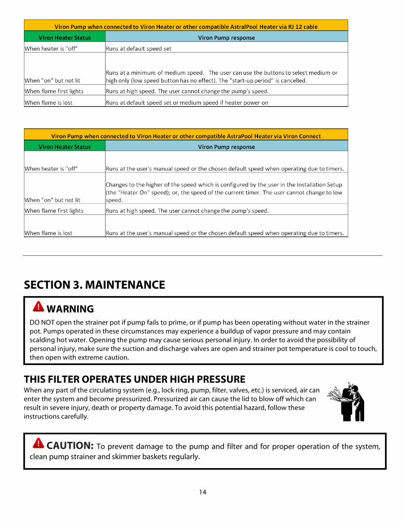
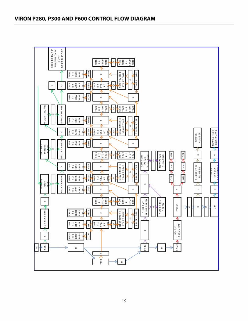
VIRON P280, P300 AND P600 CONTROL FLOW DIAGRAM
M CLK
EE
EE
M
M
TIME
R 1
LOW
SPEE D
TIME
R 1
MED
SPEE D
TIME
R 1
HIGH
SPEE D
TIME
R 2
LOW
SPEE D
TIME
R 2
MED
SPEE D
TIME
R 2
HIGH
SPEE D
TIME
R 3
LOW
SPEE D
TIME
R 3
MED
SPEE D
TIME
R 3
HIGH
SPEE D
TIME
R 4
LOW
SPEE D
TIME
R 4
MED
SPEE D
TIME
R 4
HIGH
SPEE D
LOW
MED
HIGH
LOW
MED
HIGH
LOW
MED
HIGH
LOW
MED
HIGH
TMR
E
TIME
R 1
STA
RT
TIME
E
TIME
R 1
STOP
TIME
E
TIME
R 2
STA
RT
TIME
E
TIME
R 2
STOP
TIME
E
TIME
R 3
STA
RT
TIME
E
TIME
R 3
STOP
TIME
E
TIME
R 4
STA
RT
TIME
E
TIME
R 4
STOP
TIME
<><>
<><>
<><>
<><>
M
PRIM M
OFF
<>ON
CONF
E
ON
<>OFF
E<>
E<>
CURREN
T PR
IME SP
EED
NEW
PRIM
ESP
EED
<>
NEW
PRIM
EDURATION
CURREN
T PR
IME
DURATION
E
CURREN
T ID
NUMBER
NEW
SCREE
NBRIGHT
NES
S
NEW
IDNUMBER
E
CURREN
T TIME
PROMPT
HO
UR
FLA
SH
HOUR CHA
NGES
<>
<>
HOLD
E3 SE
CONDS
DIMMIDM
TMRS
CURREN
T SC
REE
NBRIGHT
NES
S
PROMPT
MINUTE
FL
ASH
MINUTE
CHA
NGES
<>
NEW
TIM
ER 4
START TIME
NEW
TIM
ER 3
START TIME
NEW
TIM
ER 1
START TIME
TIMER
4 OFF
<>
TIMER
3 OFF
<>
TIMER
2 OFF
<>
TIMER
1 OFF
<>
NEW
TIM
ER 1
START TIME
PROMPT
AM/PM
<>
AM/PM CHA
NGES
EGOES
TO TMR IF
TU
RNED
ON IN
CONF
OR PRIM
IF NOT
EE
E
NEW
TIME
R 1
STOP
TIME
NEW
TIME
R 4
STOP
TIME
NEW
TIME
R 3
STOP
TIME
NEW
TIME
R 2
STOP
TIME
20
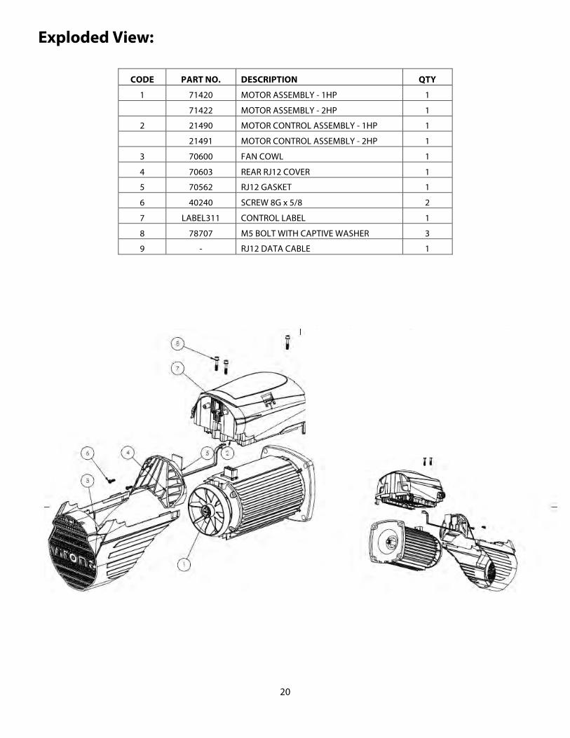
Exploded View:
CODE PART NO. DESCRIPTION QTY
1 71420 MOTOR ASSEMBLY - 1HP 1
71422 MOTOR ASSEMBLY - 2HP 1
2 21490 MOTOR CONTROL ASSEMBLY - 1HP 1
21491 MOTOR CONTROL ASSEMBLY - 2HP 1
3 70600 FAN COWL 1
4 70603 REAR RJ12 COVER 1
5 70562 RJ12 GASKET 1
6 40240 SCREW 8G x 5/8 2
7 LABEL311 CONTROL LABEL 1
8 78707 M5 BOLT WITH CAPTIVE WASHER 3
9 - RJ12 DATA CABLE 1
21
CODE PART NO. DESCRIPTION QTY
1 71420 MOTOR ASSEMBLY - 1HP 1
71422 MOTOR ASSEMBLY - 2HP 1
2 21490 MOTOR CONTROL ASSEMBLY - 1HP 1
21491 MOTOR CONTROL ASSEMBLY - 2HP 1
3 70600 FAN COWL 1
4 70603 REAR RJ12 COVER 1
5 70562 RJ12 GASKET 1
6 40240 SCREW 8G x 5/8 2
7 LABEL311 CONTROL LABEL 1
8 78707 M5 BOLT WITH CAPTIVE WASHER 3
9 - RJ12 DATA CABLE 1

22
REPLACEMENT PARTS:
Code Part No. Description Qty 1 53977-78736 BX Volute 1
53976-78735 CTX Volute 1 2 53977-78106 BX Pump Lid O-ring 1
53976-70006 CTX Pump Lid O-ring 1 3 53977-40086 BX Pump Clear Lid 1
53976-40087 CTX Pump Clear Lid 1 4 53977-40068 BX Pump Lid Collar 1
53976-40088 CTX Pump Lid Collar 1 5 53977-950925 BX 2” Union Tail 2
53977-950924 BX 1.5” Union Tail 2 53976-950920 CTX Union Tail (2”) 2 53976-950918 CTX Union Tail (1.5”) 2
6 53977-950926 BX Union Lock Nut 2 53976-950919 CTX Union Lock Nut 2
7 53976-78737 CTX/BX Seal Plate 1 8 53976-70003 CTX Union O-ring 2
53976-78104 BX Union O-ring 2 10 53976-4008101 BX ( 0.75HP) CTX (1.0HP) Impeller 1
53976-4008102 BX ( 1.0HP) CTX (1.5HP) Impeller 1 53976-4008103 BX ( 1.5HP) CTX (2.0HP) Impeller 1 53976-4008104 BX ( 2.0HP) CTX (2.5HP) Impeller 1 53976-4008105 Impeller 3.0HP 1
11 53976-78720 Diffuser 0.5HP - 2.5HP 1 53976-78721 Diffuser 3.0HP 1
13 53977-40066 BX Pump Basket 1 53976-40065 CTX Pump Basket 1
14 53976-78104 Diffuser O-ring 1 15 53976-4005002 CTX/BX Molded Motor Foot 1 16 53976-40056 CTX/BX Motor Foot Rubber Mount 1 17 53976-40111 5/16” UNC bolt HEX SS 6 and 4 18 53976-70004 CTX/BX Seal Plate O-ring 1 19 Drain Plug 2 20 Option 3” adapter 2 21 Optional Universal Base 1 22 53976-40110 3/8” UNC bolt HEX SS 4
Not Shown 53976-75508 Mechanical Seal 3/4” 1 Not Shown 53976-40165 Screw self-tap SS 2 Not Shown 53976-40112 CTX 5/16-2.25” UNC HEX SS 2
23
WARRANTY
AstralPool manufactures its products with the highest standards of workmanship, using the best materials available through state of the art processes. AstralPool warrants its products as follows:
LIMITED WARRANTY: ASTRALPOOL WARRANTS ITS PRODUCTS TO BE FREE FROM DEFECTS IN MATERIAL AND/OR WORKMANSHIP FOR A PERIOD OF ONE (1) YEAR (PARTS ONLY) FROM THE ORIGINAL DATE OF PURCHASE OR INSTALLATION. SPECIFIC PRODUCT WARRANTIES (FROM DATE OF INSTALLATION):
PRODUCT LIMITED
WARRANTY EXCEPTIONS
P-280 Variable Speed Pump 2 year Excludes Motor Bearings/O Rings-Gaskets/Seals
Viron P-300 Variable Speed Pump 2 year Excludes Motor Bearings / O Rings-Gaskets / Seals -*(1) System
Warranty 3 year
Viron P-600 Variable Speed Pump 2 year Excludes Motor Bearings / O Rings-Gaskets / Seals -*(1) System
Warranty 3 year
* (1) - Viron Builder Extended System Warranty - Must install a minimum of two Viron products- includes 1 year in field labor
Exceptions that could result in denial of a warranty claim:
Damage caused by careless handling, improper repackaging, or shipping. Damage due to misapplication, misuse, abuse or failure to operate equipment as specified in the owner’s
manual. Damage caused by failure to install products as specified in the owner’s manual. Damage due to unauthorized product modifications or failure to use AstralPool original replacement parts. Damage caused by negligence, or failure to properly maintain products as specified in the owners manual. Damage caused by failure to maintain water chemistry in conformity with the standards of the swimming pool
industry for any length of time. Damage caused by water freezing inside the product. Accidental damage, fire, acts of God, or other circumstances outside the control of AstralPool.
WARRANTY OBLIGATIONS OF ASTRALPOOL Should a defect in workmanship and/or material in any item covered by this warranty become evident during the term of the warranty, then upon the consumer following the procedures set forth below, AstralPool will, at its option, repair or replace such item or part at its own cost and expense. AstralPool is not, however, responsible under this warranty for any cost of shipping or transportation of the equipment or parts thereof to or from the Technical Service Department. Also, AstralPool is not liable for any loss of time, inconvenience, incidental expenses such as telephone calls, labor or material charges incurred in connection with the removal or replacement of the equipment, or any other incidental or consequential damages.
24
LISTED AND TESTED BASED ON UL 1081
FOR USE WITH SWIMMING POOLS AND SPAS
This warranty is void if the product is repaired or altered in any way by any persons, agents or representatives other than those authorized by AstralPool. Expendables including, but not limited to refrigerant, recovery of refrigerant, or transportation for components are not covered under this limited warranty. Reasonable vehicle trip and evaluation charges may be assessed by the service representative. AstralPool, at its sole discretion, reserves the right to provide a replacement product or part, of equal value, in lieu of repair. Some states do not allow the exclusion or limitation of incidental or consequential damages, so the above limitation or exclusion may not apply to you. Except as stated in this section, AstralPool, its subsidiaries and affiliates make no warranties, express, implied or statutory, as to any matter whatsoever. In particular, any and all warranties of merchantability or fitness for a particular purpose and noninfringement of third party rights are expressly excluded. PROCEDURE FOR OBTAINING RETURN GOODS AUTHORIZATION In order to obtain the benefits of this warranty, the consumer who made the original retail purchase must contact the AstralPool Technical Service Department as soon as possible after discovery of the defect, but in no event later than the expiration date of the warranty period provided in this warranty. Upon receipt of this communication, AstralPool will promptly notify the customer of the address to which the defective item may be shipped. The customer shall then ship the item, freight prepaid by customer, to the address indicated, together with a “RETURN GOODS AUTHORIZATION” form obtained from Technical Service and a brief description of the problems encountered. Unauthorized returns will not be accepted. Freight must be prepaid by customer. WARRANTIES OR REPRESENTATIONS BY OTHERS No dealer or other person has any authority to make any warranties or representation concerning AstralPool or its products. Accordingly, AstralPool is not responsible for any such warranties or representations. SOLE WARRANTY Supersedes all previous publications.
Fluidra USA, LLC. 8525 Mallory Road Jacksonville, FL 32220 Phone (904) 378-0999 Fax (904) 378-0488