Embed Size (px)
Citation preview

OWNER’S MANUALFOR
DRY VACUUM PUMPSMODELS:
20142032 / 20422034 / 20442037 / 2047
Gardner Denver Welch Vacuum Technology5621 W. Howard StreetNiles, IL 60714Phone: (847) 676-8800 Fax: (847) 677-8606 (Technical Support) E-Mail: [email protected] Part No. 642779Web-Page: www.welchvacuum.com Printed in USA
Agency:
WARNINGBe sure to properly identify intake and exhaust
before using the pump. See Section 2.15
CAUTIONDo not pump liquids with the pump. Pumpingliquids will cause the pump to stop working.
INSTRUCTIONWARNING AND CAUTION
PLEASE READ BEFORE OPERATION
While reading your manual, please pay close attention to areas labeled: WARNING AND CAUTION.
The description of each is found below.
WARNINGWarnings are given where failure to observe instruction could result
in injury or death to people.
CAUTIONCautions are found where failure to observe the instruction could result
in damage to the equipment, associated equipment and process.
These units conform to the SI International system of units of measurement.
The following symbols (with recommendation of IEC1010 ) of warning will be found on the pump.
Caution - refer to accompanying documents
Caution - risk of electrical shock
Caution - hot surface
WARNINGMotor includes a self resetting thermal cutout and the pump could
restart without actuation under fault condition.
2
TABLE OF CONTENTS Section Page
Section 01 - Safety Information 1.10 Caution: to prevent injury 4 1.20 Caution: to reduce risk of electrical shock 4 1.30 Warning: to reduce risk of electricution 5 1.40 Warning:toreduceriskofexplosionorfire 5
Section 02 - Installation 2.10 Enviromental conditions 6 2.11 Introduction 6 2.12 Unpacking 6 2.13 Pump mounting 6 2.14 Pump location 6 2.15 Discharge provisions 7 2.16 Electrical power 8 2.17 Advanced Vapor Management (AVM) 8 2.18 Traps 8 2.19 The care of a liquid trap 9 2.20 The care of a cold trap 9
Section 03 - Operation 3.10 Starting a Welch DRY Vacuum Pump 10 3.11 Cleanliness 10 3.12 Leak detection 10 3.13 Operating pressure range 10 3.14 The effects of unwanted vapor 10 3.15 Shutdown procedure 10
Section 04 - Maitenance 4.10 General maintenance 11 4.11 Diaphragm removal 11 4.12 Installation of new diaphragm 11
Section 05 - Application 5.10 Operation as a replacement for aspirators 12 5.20 Cross reference Welch DRY Pump to Water Aspirator 12
Section 06 - Specifications 6.10 SpecificationChart 13
Section 07 - Specifications Warranty 14
Section 08 - Drawings 8.10 Dimensional drawing 15 8.20 Exploded view and kit for 2034, 2037 & 2044 16 8.30 Exploded view and kit for 2014, 2032, 2042 & 2047 17
3
4
Section 1: SAFETY INFORMATION
1.10 Caution: To Prevent Injury...1.11 Never operate this product if it has a damaged cord or plug. If it is not working properly, has been dropped, damaged or has fallen into water, please return the product to a Welch service center for examination and repair.
1.12 Keep the cord away from heated surfaces.All electrical products generate heat. To avoid serious burns never touch unit during or immediately after operation.
1.13 Never block any air openings or place it on a soft surface where the openings may be blocked. To ensure proper ventilation, keep unit a minimum of one inch from any wall or obstruction. The air openings are for ventilation of the motor inside the housing.
1.14 Models 2014, 2032, 2034, 2037, 2042, 2044 and 2047 are thermally protected and can automatically restart when the protector resets. Always disconnect power source before servicing.
1.15 Neverdroporinsertfingersoranyotherobjectintoanyopenings.
1.16 Do not operate this product where oxygen is being administered.
1.17 Wear safety glasses and goggles when operating this product.
1.18 Use only in well ventilated areas. The motor on all pumps are totally enclosed fan cooled
1.19 Be sure to properly identify intake and discharge before using pump. See Section 2.5.
Models 2014, 2032, 2034, 2037, 2042, 2044 and 2047 have one exhaust port on the pump. See Section 2.15.
1.20 Caution: To Reduce Risk Of Electrical Shock...1.21 Do not disassemble. Disassembly or attempted repairs if accomplished incorrectly can create electricalshockhazard.Referservicingtoqualifiedserviceagenciesonly.
1.22 Unit is supplied with a three pronged plug. Be sure to connect pump to a properly grounded outlet only.
WARNINGDo not operate the pumps in an atmosphere containing
flammable or explosive gases/vapors.
WARNINGRemove plug from Exhaust Port before using.
5
1.30 Warning: To Reduce Risk of Electrocution...1.31 Do not use this product in or near area where it can fall or be pulled into water or other liquids.
1.32 Do not reach for this product if it has fallen into liquid. Unplug immediately.
1.33 Never operate this product outdoors in the rain or in a wet area.
1.40 Danger: To Reduce Risk of Explosion or Fire...1.41 Do not use this pump in or near explosive atmospheres or where aerosol (spray) products are being used.
1.42 Donotusethisproductnearflames.
WARNINGFailure to observe the above safety precautions could result in
Severe bodily injury, including death in some cases.
6
Section 2: INSTALLATION
2.10 Environmental Conditions The Pump is rated for indoor use only. Maximum altitude 2000 meters. Operating temperature range 10oC to 40oC. Maximum relative humidity of 80% for temperatures up to 31oC decreasing to 50% at 40oC. Rated for +/-10% of supply voltage. Pollution Degree 2, Installation Category II.
2.11 Introduction This manual has been compiled not only for the care and maintenance of the Welch Dryfast Vacuum pump now in your possession, but as a helpful reference and guide to prevent many problems which can occur if used improperly.
2.12 Unpacking Carefully remove the Dryfast Vacuum pump from the shipping case. Preserve all paperwork for future reference.Ifdamagehasoccurredfromshipmentaclaimmustbefiledwiththecarrierimmediately; preserve the shipping carton for inspection by the carrier. If you are required to communicate with yourdealerorWelchVacuumbesuretoincludeyourordernumbersforquickidentification. Do not return the pump to the factory without obtaining returned goods authorization. *See “Service & Support” on www.welchvacuum.com.
2.13 Pump Mounting Rubber feet are attached to the pump casing.
2.14 Pump Location
The Dryfast Vacuum pump should be located preferably in a clean, dry and well ventilated area. Please be sure not to block the ventilation ports located on the motor housing. The pump should be placed where the surrounding temperature remains between 10oC and 40oC (50oF and 104oF). Always check to insure the location chosen is protected from direct or indirect moisture contact. The pump should belocatedascloselytoitssysteminordertoutilizeitmostefficiently.
WARNINGDon’t operate this pump in an atmosphere
containing flammable or explosive gas.
WARNINGThe motor is thermally protected and will automatically restart
unexpectedly when the overload device resets.
7
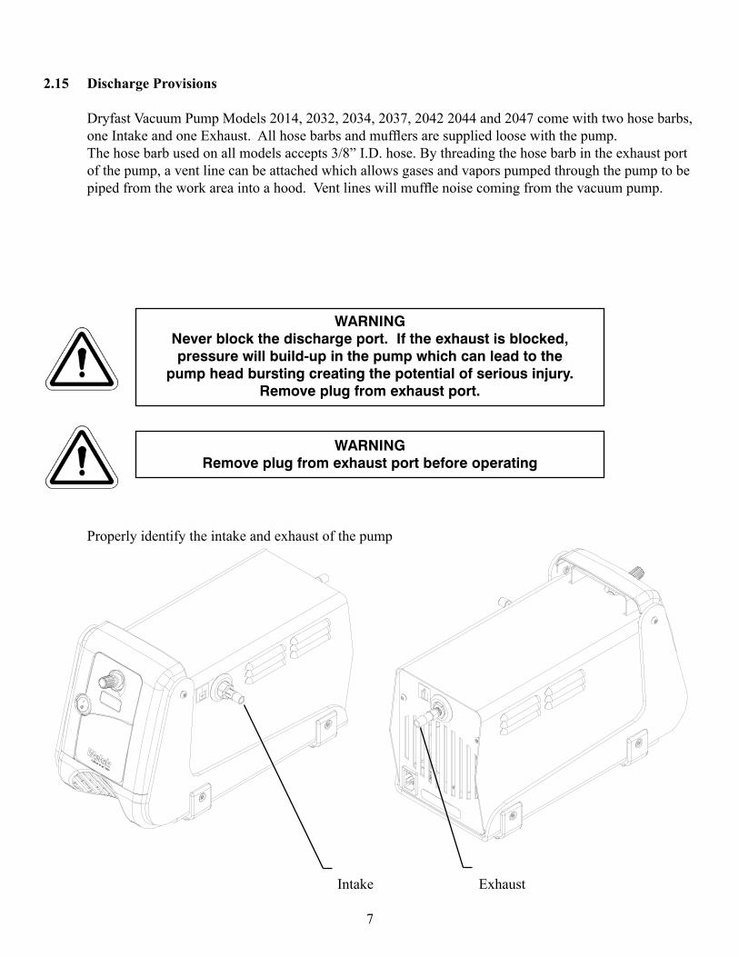
2.15 Discharge Provisions Dryfast Vacuum Pump Models 2014, 2032, 2034, 2037, 2042 2044 and 2047 come with two hose barbs, oneIntakeandoneExhaust.Allhosebarbsandmufflersaresuppliedloosewiththepump. The hose barb used on all models accepts 3/8” I.D. hose. By threading the hose barb in the exhaust port of the pump, a vent line can be attached which allows gases and vapors pumped through the pump to be pipedfromtheworkareaintoahood.Ventlineswillmufflenoisecomingfromthevacuumpump.
Properly identify the intake and exhaust of the pump
Intake Exhaust
WARNINGNever block the discharge port. If the exhaust is blocked, pressure will build-up in the pump which can lead to the
pump head bursting creating the potential of serious injury. Remove plug from exhaust port.
WARNINGRemove plug from exhaust port before operating
2.16 Electrical Power 2.161 Power Source Review Review the power source and the motor rating to be sure they agree in voltage, phase and frequency. Serious damage may occur to the motor if it is connected to an improper voltage. All Welch pumps must be grounded. Grounding reduces the risk of electric shock in the event of an electrical short circuit. The plug must be plugged into an outlet properly grounded. Consult your local electrical codes if you have doubts. IdentificationSymbols:
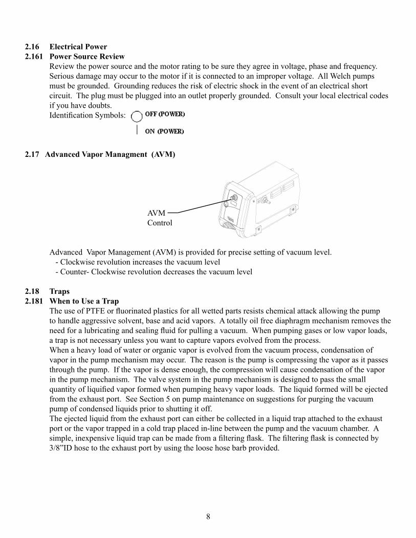
2.17 Advanced Vapor Managment (AVM)
AVM Control
Advanced Vapor Management (AVM) is provided for precise setting of vacuum level. - Clockwise revolution increases the vacuum level - Counter- Clockwise revolution decreases the vacuum level
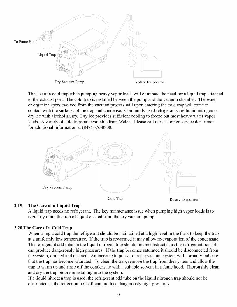
2.18 Traps2.181 When to Use a Trap TheuseofPTFEorfluorinatedplasticsforallwettedpartsresistschemicalattackallowingthepump to handle aggressive solvent, base and acid vapors. A totally oil free diaphragm mechanism removes the needforalubricatingandsealingfluidforpullingavacuum.Whenpumpinggasesorlowvaporloads, a trap is not necessary unless you want to capture vapors evolved from the process. When a heavy load of water or organic vapor is evolved from the vacuum process, condensation of vapor in the pump mechanism may occur. The reason is the pump is compressing the vapor as it passes through the pump. If the vapor is dense enough, the compression will cause condensation of the vapor in the pump mechanism. The valve system in the pump mechanism is designed to pass the small quantityofliquifiedvaporformedwhenpumpingheavyvaporloads.Theliquidformedwillbeejected from the exhaust port. See Section 5 on pump maintenance on suggestions for purging the vacuum pump of condensed liquids prior to shutting it off. The ejected liquid from the exhaust port can either be collected in a liquid trap attached to the exhaust port or the vapor trapped in a cold trap placed in-line between the pump and the vacuum chamber. A simple,inexpensiveliquidtrapcanbemadefromafilteringflask.Thefilteringflaskisconnectedby 3/8”ID hose to the exhaust port by using the loose hose barb provided.
8
9
The use of a cold trap when pumping heavy vapor loads will eliminate the need for a liquid trap attached to the exhaust port. The cold trap is installed between the pump and the vacuum chamber. The water or organic vapors evolved from the vacuum process will upon entering the cold trap will come in contact with the surfaces of the trap and condense. Commonly used refrigerants are liquid nitrogen or dryicewithalcoholslurry.Dryiceprovidessufficientcoolingtofreezeoutmostheavywatervapor loads. A variety of cold traps are available from Welch. Please call our customer service department. for additional information at (847) 676-8800.
2.19 The Care of a Liquid Trap A liquid trap needs no refrigerant. The key maintenance issue when pumping high vapor loads is to regularly drain the trap of liquid ejected from the dry vacuum pump.
2.20 The Care of a Cold Trap Whenusingacoldtraptherefrigerantshouldbemaintainedatahighlevelintheflasktokeepthetrap at a uniformly low temperature. If the trap is rewarmed it may allow re-evaporation of the condensate. The refrigerant add tube on the liquid nitrogen trap should not be obstructed as the refrigerant boil-off can produce dangerously high pressures. If the trap becomes saturated it should be disconnected from the system, drained and cleaned. An increase in pressure in the vacuum system will normally indicate that the trap has become saturated. To clean the trap, remove the trap from the system and allow the trap to warm up and rinse off the condensate with a suitable solvent in a fume hood. Thoroughly clean and dry the trap before reinstalling into the system. If a liquid nitrogen trap is used, the refrigerant add tube on the liquid nitrogen trap should not be obstructedastherefigerantboil-offcanproducedangerouslyhighpressures.
Dry Vacuum Pump
Dry Vacuum Pump
Liquid Trap
Cold Trap
Rotary Evaporator
Rotary Evaporator
To Fume Hood
10
Section 3: OPERATION
3.10 Starting a Welch Dry Vacuum Pump Before attaching the pump to a system it is well to familiarize yourself with the function and action of the pressure vacuum pump which you have acquired. Review the power requirements as described in Section 2.6. Welch recommends running the pump for a few minutes to warm it up before use. The warm-up improves the pumps ability to pass water and organic vapor. A warm pump will handle more vapor without liquifying it than a cold pump.
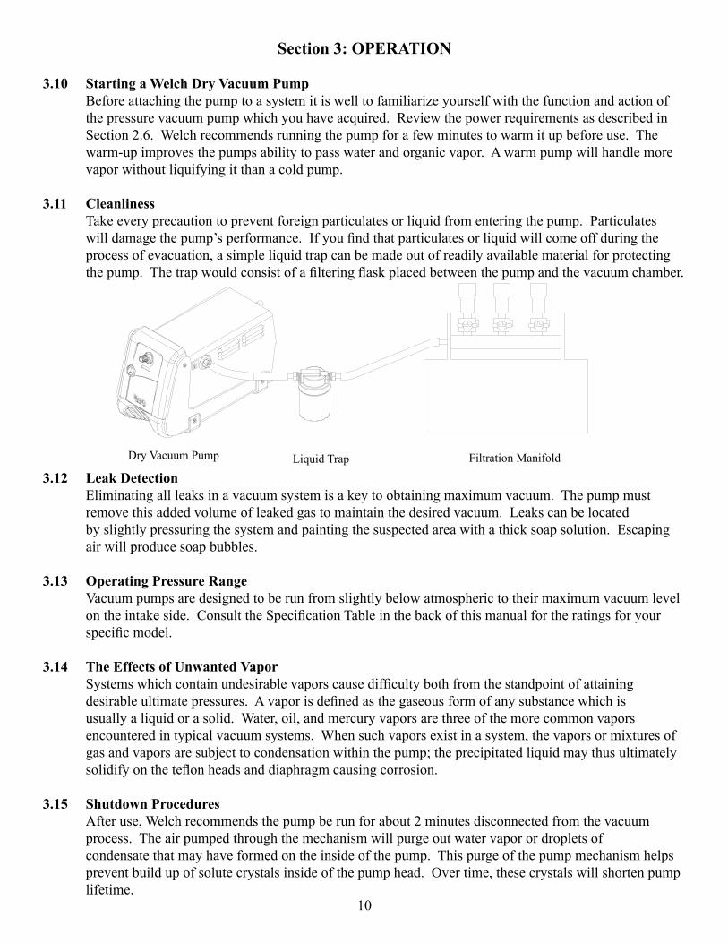
3.11 Cleanliness Take every precaution to prevent foreign particulates or liquid from entering the pump. Particulates willdamagethepump’sperformance.Ifyoufindthatparticulatesorliquidwillcomeoffduringthe process of evacuation, a simple liquid trap can be made out of readily available material for protecting thepump.Thetrapwouldconsistofafilteringflaskplacedbetweenthepumpandthevacuumchamber.
3.12 Leak Detection Eliminating all leaks in a vacuum system is a key to obtaining maximum vacuum. The pump must remove this added volume of leaked gas to maintain the desired vacuum. Leaks can be located by slightly pressuring the system and painting the suspected area with a thick soap solution. Escaping air will produce soap bubbles.
3.13 Operating Pressure Range Vacuum pumps are designed to be run from slightly below atmospheric to their maximum vacuum level ontheintakeside.ConsulttheSpecificationTableinthebackofthismanualfortheratingsforyour specificmodel.
3.14 The Effects of Unwanted Vapor Systemswhichcontainundesirablevaporscausedifficultybothfromthestandpointofattaining desirableultimatepressures.Avaporisdefinedasthegaseousformofanysubstancewhichis usually a liquid or a solid. Water, oil, and mercury vapors are three of the more common vapors encountered in typical vacuum systems. When such vapors exist in a system, the vapors or mixtures of gasandvaporsaresubjecttocondensationwithinthepump;theprecipitatedliquidmaythusultimately solidifyontheteflonheadsanddiaphragmcausingcorrosion.
3.15 Shutdown Procedures After use, Welch recommends the pump be run for about 2 minutes disconnected from the vacuum process. The air pumped through the mechanism will purge out water vapor or droplets of condensate that may have formed on the inside of the pump. This purge of the pump mechanism helps prevent build up of solute crystals inside of the pump head. Over time, these crystals will shorten pump lifetime.
Liquid Trap Filtration ManifoldDry Vacuum Pump
11
Section 4: MAINTENANCE
4.10 General Maintenance Welch Dryfast Vacuum units are 100% oil-free. The pump employs a diaphragm with an uninterrupted Teflon®coating.Allbearingsaresealedandpermanentlylubricated.Lubricationshouldnotbe attempted. The units are built for duty operation just like a water aspirator, but with the quietness, performance and durability of a diaphragm.
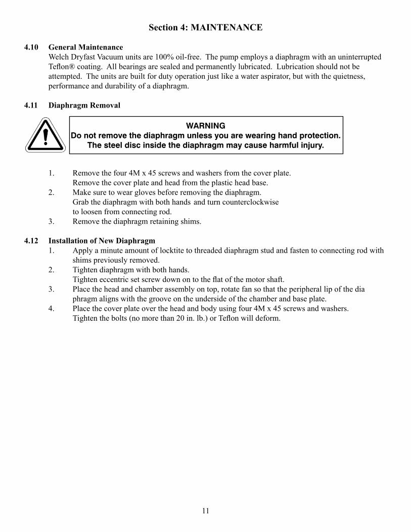
4.11 Diaphragm Removal
1. Remove the four 4M x 45 screws and washers from the cover plate. Remove the cover plate and head from the plastic head base. 2. Make sure to wear gloves before removing the diaphragm. Grab the diaphragm with both hands and turn counterclockwise to loosen from connecting rod. 3. Remove the diaphragm retaining shims.
4.12 Installation of New Diaphragm 1. Apply a minute amount of locktite to threaded diaphragm stud and fasten to connecting rod with shims previously removed. 2. Tighten diaphragm with both hands. Tighteneccentricsetscrewdownontotheflatofthemotorshaft. 3. Place the head and chamber assembly on top, rotate fan so that the peripheral lip of the dia phragm aligns with the groove on the underside of the chamber and base plate. 4. Place the cover plate over the head and body using four 4M x 45 screws and washers. Tightenthebolts(nomorethan20in.lb.)orTeflonwilldeform.
WARNINGDo not remove the diaphragm unless you are wearing hand protection.
The steel disc inside the diaphragm may cause harmful injury.
Section 5: APPLICATION
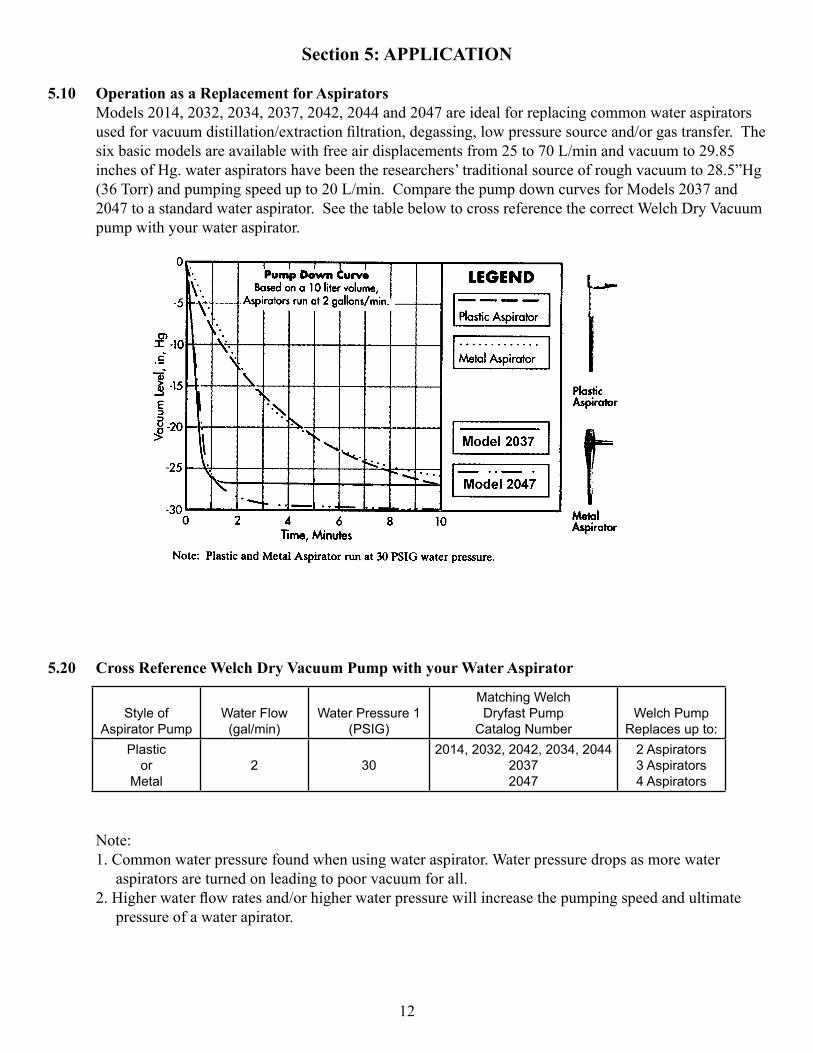
5.10 Operation as a Replacement for Aspirators Models 2014, 2032, 2034, 2037, 2042, 2044 and 2047 are ideal for replacing common water aspirators usedforvacuumdistillation/extractionfiltration,degassing,lowpressuresourceand/orgastransfer.The six basic models are available with free air displacements from 25 to 70 L/min and vacuum to 29.85 inches of Hg. water aspirators have been the researchers’ traditional source of rough vacuum to 28.5”Hg (36 Torr) and pumping speed up to 20 L/min. Compare the pump down curves for Models 2037 and 2047 to a standard water aspirator. See the table below to cross reference the correct Welch Dry Vacuum pump with your water aspirator.
5.20 Cross Reference Welch Dry Vacuum Pump with your Water Aspirator
Note: 1. Common water pressure found when using water aspirator. Water pressure drops as more water aspirators are turned on leading to poor vacuum for all. 2.Higherwaterflowratesand/orhigherwaterpressurewillincreasethepumpingspeedandultimate pressure of a water apirator.
12
Style of Aspirator Pump
Water Flow (gal/min)
Water Pressure 1(PSIG)
Matching Welch Dryfast Pump
Catalog NumberWelch Pump
Replaces up to:Plastic
orMetal
2 302014, 2032, 2042, 2034, 2044
20372047
2 Aspirators3 Aspirators4 Aspirators
13
Section 6: SPECIFICATION
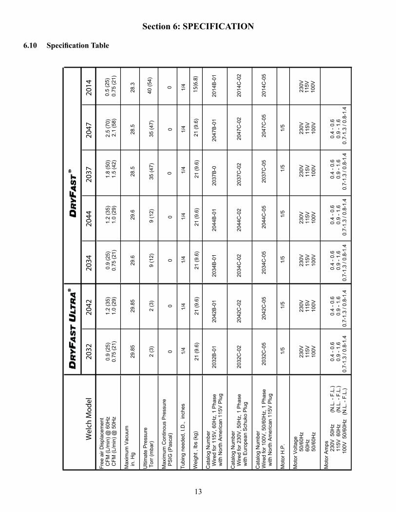
6.10 Specification Table
Wel
ch M
odel
2032
2042
2034
2044
2037
2047
2
014
Free
air
Dis
plac
emen
t C
FM (L
/min
) @ 6
0Hz
0.9
(25)
1.
2 (3
5)
0.9
(25)
1.
2 (3
5)
1.8
(50)
2.
5 (7
0)
CFM
(L/m
in) @
50H
z 0.
75 (2
1)1.
0 (2
9)
0.
75 (2
1)1.
0 (2
9)
1.5
(42)
2.
1 (5
8)
Max
imum
Vac
uum
i
n. H
g 29
.85
29.8
5 29
.6
29.6
28
.5
28.5
Ulti
mat
e P
ress
ure
Tor
r (m
bar)
2
(3)
2 (3
) 9
(12)
9
(12)
35
(47)
35
(47)
Max
imum
Con
tinou
s P
ress
ure
PS
IG (P
asca
l) 0
0 0
0 0
0
Tubi
ng n
eede
d, I.
D.,
inch
es
1/4
1/4
1/4
1/4
1/4
Wei
ght ,
lbs
(kg)
21
(9.6
) 21
(9.6
) 21
(9.6
) 21
(9.6
) 21
(9.6
) 21
(9.6
)
Cat
alog
Num
ber
Wire
d fo
r 115
V, 6
0Hz,
1 P
hase
20
32B
-01
2042
B-0
120
34B
-01
2044
B-0
120
37B
-0
2047
B-0
1
2
014B
-01
with
Nor
th A
mer
ican
115
V P
lug
Cat
alog
Num
ber
Wire
d fo
r 230
V, 5
0Hz,
1 P
hase
20
32C
-02
2042
C-0
220
34C
-02
2044
C-0
220
37C
-02
2047
C-0
2
2
014C
-02
with
Eur
opea
n S
chuk
o P
lug
Cat
alog
Num
ber
Wire
d fo
r 100
V, 5
0/60
Hz,
1 P
hase
2032
C-0
520
42C
-05
2034
C-0
520
44C
-05
2037
C-0
520
47C
-05
2
014C
-05
with
Nor
th A
mer
ican
115
V P
lug
Mot
or H
.P.
1/5
1/5
1/5
1/5
1/5
1/5
Mot
or V
olta
ge
50/6
0Hz
230V
23
0V
230V
23
0V
230V
23
0V
60H
z 11
5V
115V
11
5V
115V
11
5V
115V
50
/60H
z 10
0V
100V
10
0V
100V
10
0V
100V
Mot
or A
mps
23
0V 5
0Hz
(N.L
. - F
.L.)
0.4
- 0.6
0.
4 - 0
.6
0.4
- 0.6
0.
4 - 0
.6
0.4
- 0.6
0.
4 - 0
.6
115V
60H
z
(N
.L. -
F.L
.)0.
9 - 1
.6
0.9
- 1.6
0.
9 - 1
.6
0.9
- 1.6
0.
9 - 1
.6
0.9
- 1.6
10
0V 5
0/60
Hz
(N
.L. -
F.L
.)0.
7-1.
3 / 0
.8-1
.40.
7-1.
3 / 0
.8-1
.40.
7-1.
3 / 0
.8-1
.40.
7-1.
3 / 0
.8-1
.40.
7-1.
3 / 0
.8-1
.40
.7-1
.3 /
0.8-
1.4
1/4
0.5
(25)
0.75
(21)
28.3
40 (5
4)
0 1/4
230V
11
5V
100V
15(6
.8)
14
Section 7: WARRANTY
UNPACKING Inspectthepumpcarefully.Ifanydamagehasoccurred,fileclaimwiththecarrierimmediately. Save the shipping container for carrier to inspect.
OPERATING PUMP Refer to the enclosed Instruction/Operation Manual for all information to properly operate and maintain the pump.
WARRANTY This Welch Vacuum product is warranted to be free from defects in material and workmanship. The liability of Gardner Denver Welch Vacuum Technology, Inc. under this warranty is limited to servicing, adjusting, repairing or replacing any unit or component part which in the judgment of Gardner Denver Welch Vacuum Technology, Inc. has not been misused, abused or altered in any way causing impaired performance or rendering it inoperative. No other warranties are expressed or implied. The method of executing this warranty: servicing, adjusting, repairing or replacing shall be at the discretion of Gardner Denver Welch Vacuum Technology, Inc. Vacuum pumps that have been used for any period, however short, will be repaired under this warranty rather than replaced.
The warranty is effective for one year from the date of original purchase when:
1. The warranty card has been completed and returned. 2. The product is returned to the factory or other designated service centers, freight prepaid. 3. The product in our judgment is defective through no action or fault of the user.
If the product has become defective through misuse, abuse, or alteration, repairs will be billed regardless of the age of the product. In this event, an estimate of the repair costs will be submitted and authorization of these charges will be required before the product is repaired and returned.
Toobtainareturnauthorizationnumber,pleasefillintheon-linerequestformonwww/welchvacuum.com.Products without a return authorization number will be refused by our receiving department. Before shipping, properly pack the pump, insure it against loss or damage, and on the outside of the pump packaging and the packing slip write in the return authorization number. Pumps damaged due to improper packaging are the cus-tomer’s responsibility.
15
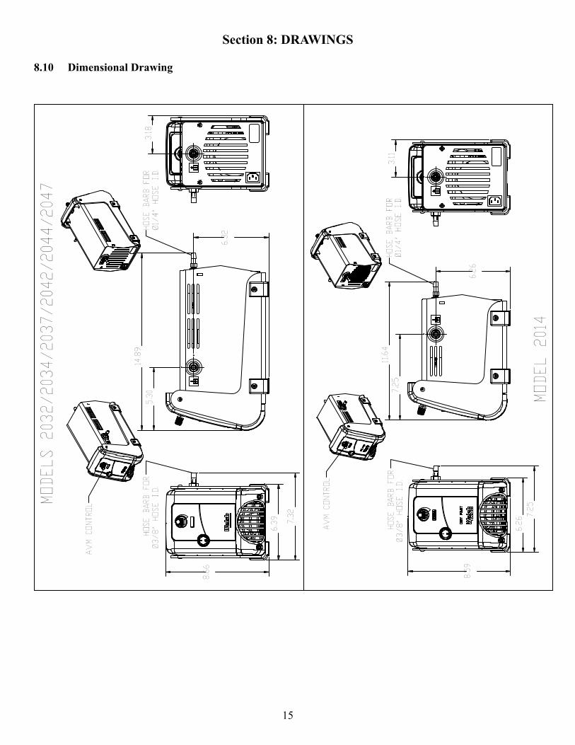
Section 8: DRAWINGS
8.10 Dimensional Drawing
7.25
6.26
8.59
7.25
11.64
3.11
6.26
6.39 7.32
8.66
5.30
14.89
3.18
6.32
MODELS 2032/2034/2037/2042/2044/2047
MODEL 2014
HOSE BARB FOR
Ø3/8" HOSE I.D.
HOSE BARB FOR
Ø1/4" HOSE I.D.
AVM CONTROL
HOSE BARB FOR
Ø3/8" HOSE I.D.
HOSE BARB FOR
Ø1/4" HOSE I.D.
AVM CONTROL
16
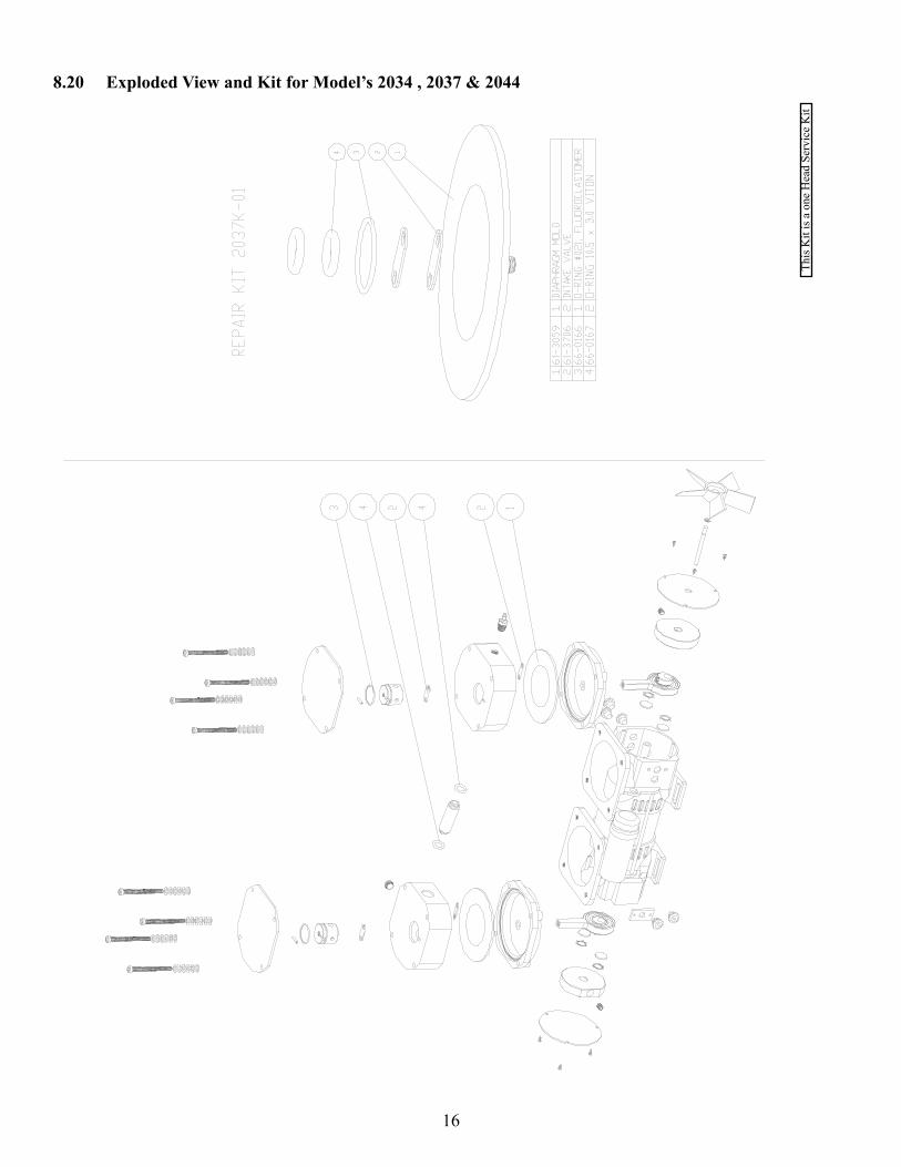
8.20 Exploded View and Kit for Model’s 2034 , 2037 & 2044
This
Kit
is a
one
Hea
d Se
rvic
e K
it
17
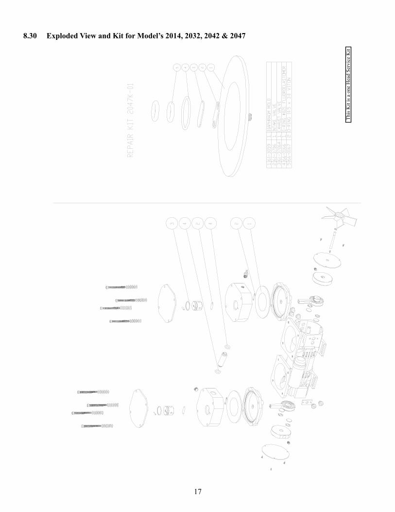
8.30 Exploded View and Kit for Model’s 2014, 2032, 2042 & 2047
This
Kit
is a
one
Hea
d Se
rvic
e K
it

Gardner Denver Thomas Inc.Welch Vacuum Technology
Vacuum Pump Repair Facility 5621 W. Howard Street Niles, IL 60714 Phone: (847) 676-8800 Fax: (847) 677-8606 (Technical Support)
Copyright© 1997-2007 Gardner Denver Welch Vacuum Technology
Welch is registered trademarks of Gardner Denver