Embed Size (px)
Citation preview

G5 Controller ModelsPL800, PL1600, PL4800
Owner’s Manual
PGMPROGRAM
NEXT
BACK
UP
PRESS TO STARTMANUAL PROGRAM
DOWN
ENGLISH
ESPAÑOL
LANGUAGE
SYSTEM OFF
ADVANCEDMENU
RUN
MANUAL PROGRAM
MULTIMETER
VALVE LOCATOR
SENSOR OPERATION
RUN AND SOAK CYCLES
CURRENT TIME / DATE
PROGRAM START TIMES
ZONE RUN TIMES
DAYS TO WATER
OMIT TIMES / DAYS
MONTHLY % ADJUST
MANUAL ZONE
MANUAL TEST
ON RAIN/FREEZESENSOR
OFF

i
Congratulations! The ProLine® controller performs timed watering and is ready for options like rain and freeze sensors, ATTENTION INSTALLER: PLEASE READ BEFORE INSTALLING AND SAVE THIS MANUAL FOR SYSTEM OWNER. INSTALLATION INSTRUCTIONS FOR EACH MODEL IS INCLUDED SEPARATELY.This controller is not intended for use by young children or the infirm without supervision. Young children should be supervised to insure they do not play with this appliance.If the supply cord is damaged it must be replaced by the manufacturer, an authorized service agent or a similarly qualified person in order to avoid a hazard. U.S. Patent No. 7,406,363TRADEMARKS: Weathermatic®
ProLine®®
Help Desk
Introduction
www.dramm.com
Online: dramm.com
Email: [email protected] Telephone: 920/684.0227
Smart Solutions for the Professional
Dramm is proud to work with Weathermatic to bring the ProLineto the horticultural market.

ii
420GLS Rain Sensor for All ProLine® Models
SLM2 2-Zone Module for PL800 only
SLM4 4-Zone Module for PL1600 only
SLM12 12-Zone Modulefor PL4800 only
RFS5Wireless rain/freeze sensor
inch
1/23/41/4 1/8
ProLine Accessories
SL-AIRCARD, SL-AIRCARDFLOW Web-based control from PC, tablet, smartphone. Flow management option

iii
1.0 Getting Acquainted With Your ProLine® Controller. . 1 1.1 Getting Acquainted With Your ProLine® Control Panel. . . . . . . . . . . . . . . . . . . . . . . . 1 1.2 Programming . . . . . . . . . . . . . . . . . . . . . . . . . . . . . . . 3
2.0 Programming . . . . . . . . . . . . . . . . . . . . . . . . . . . . . . . . . . . 3 2.1 Current Time/Date . . . . . . . . . . . . . . . . . . . . . . . . . . . 3 2.2 Program Start Times . . . . . . . . . . . . . . . . . . . . . . . . . 4 2.3 Zone Run Times . . . . . . . . . . . . . . . . . . . . . . . . . . . . . 4 2.4 Days to Water . . . . . . . . . . . . . . . . . . . . . . . . . . . . . . . 5 2.5 Omit Times/Days/Dates . . . . . . . . . . . . . . . . . . . . . . 5 2.6 Seasonal % Adjust . . . . . . . . . . . . . . . . . . . . . . . . . . . 6
3.0 Manual Start Functions . . . . . . . . . . . . . . . . . . . . . . . . . . 6 3.1 Manual Zone . . . . . . . . . . . . . . . . . . . . . . . . . . . . . . . . 6 3.2 Manual Test . . . . . . . . . . . . . . . . . . . . . . . . . . . . . . . . . 6 3.3 Manual Program . . . . . . . . . . . . . . . . . . . . . . . . . . . . . 7
4.0 System Diagnostics and Eco Features . . . . . . . . . . . . 7 4.1 Multimeter . . . . . . . . . . . . . . . . . . . . . . . . . . . . . . . . . . 7 4.2 Valve Locator . . . . . . . . . . . . . . . . . . . . . . . . . . . . . . . 8 4.3 Sensor Operation . . . . . . . . . . . . . . . . . . . . . . . . . . . . 8 4.4 Run and Soak Cycles . . . . . . . . . . . . . . . . . . . . . . . . . 9
5.0 Advanced Menu . . . . . . . . . . . . . . . . . . . . . . . . . . . . . . . . 10 5.1 FAULTS. . . . . . . . . . . . . . . . . . . . . . . . . . . . . . . . . . . . . 11 5.2 OPEN CIRCUIT FAULT . . . . . . . . . . . . . . . . . . . . . . . . 11 5.3 LANGUAGE . . . . . . . . . . . . . . . . . . . . . . . . . . . . . . . . 12 5.4 UNITS . . . . . . . . . . . . . . . . . . . . . . . . . . . . . . . . . . . . . 12 5.5 DEFAULT . . . . . . . . . . . . . . . . . . . . . . . . . . . . . . . . . . 12 5.6 GROW-IN . . . . . . . . . . . . . . . . . . . . . . . . . . . . . . . . . . 12
5.7 ABOUT . . . . . . . . . . . . . . . . . . . . . . . . . . . . . . . . . . . . 12 5.7.1 MODEL . . . . . . . . . . . . . . . . . . . . . . . . . . . . . . . . . . .12 5.7.2 VERSION. . . . . . . . . . . . . . . . . . . . . . . . . . . . . . . . . .13 5.7.3 BUILD. . . . . . . . . . . . . . . . . . . . . . . . . . . . . . . . . . . . .13 5.7.4 SER NUM. . . . . . . . . . . . . . . . . . . . . . . . . . . . . . . . . .13 5.7.5 HW VERSION . . . . . . . . . . . . . . . . . . . . . . . . . . . . . .13 5.7.6 NUM ZONES . . . . . . . . . . . . . . . . . . . . . . . . . . . . . . .13 5.7.7 EEPROM . . . . . . . . . . . . . . . . . . . . . . . . . . . . . . . . . .13 5.7.8 SLHUB VER. . . . . . . . . . . . . . . . . . . . . . . . . . . . . . . .13 5.7.9 SLHUB BLD. . . . . . . . . . . . . . . . . . . . . . . . . . . . . . . .13 5.7.10 SLAC B VER . . . . . . . . . . . . . . . . . . . . . . . . . . . . . . .13 5.7.11 SLAC B BLD . . . . . . . . . . . . . . . . . . . . . . . . . . . . . . .13 5.7.12 Z96 TYPE . . . . . . . . . . . . . . . . . . . . . . . . . . . . . . . . .13 5.7.13 Z96 VERS . . . . . . . . . . . . . . . . . . . . . . . . . . . . . . . . .13 5.8 MODBUS . . . . . . . . . . . . . . . . . . . . . . . . . . . . . . . . . . 13 5.8.1 SHORT ADD . . . . . . . . . . . . . . . . . . . . . . . . . . . . . . .13 5.9 CLR ALL. . . . . . . . . . . . . . . . . . . . . . . . . . . . . . . . . . . 13 5.10 CLR PGM . . . . . . . . . . . . . . . . . . . . . . . . . . . . . . . . . . 14 5.11 CON PGM. . . . . . . . . . . . . . . . . . . . . . . . . . . . . . . . . . 14 5.12 NC/NO MV. . . . . . . . . . . . . . . . . . . . . . . . . . . . . . . . . 14 5.13 MV/ZONE. . . . . . . . . . . . . . . . . . . . . . . . . . . . . . . . . . 14 5.14 MV/ZN DLY . . . . . . . . . . . . . . . . . . . . . . . . . . . . . . . . 14 5.15 MV2 ZONE . . . . . . . . . . . . . . . . . . . . . . . . . . . . . . . . . 14 5.16 ZN/ZN DLY . . . . . . . . . . . . . . . . . . . . . . . . . . . . . . . . 14 5.17 NUM START . . . . . . . . . . . . . . . . . . . . . . . . . . . . . . . . 15 5.18 DS TIME . . . . . . . . . . . . . . . . . . . . . . . . . . . . . . . . . . . 15 5.18.1 DST ON/OFF . . . . . . . . . . . . . . . . . . . . . . . . . . . . .15 5.18.2 DS SETUP . . . . . . . . . . . . . . . . . . . . . . . . . . . . . . . .15
Table of Contents

ivTable of Contents 5.19 RUN/SOAK. . . . . . . . . . . . . . . . . . . . . . . . . . . . . . . 15 5.20 SENSOR . . . . . . . . . . . . . . . . . . . . . . . . . . . . . . . . . 15 5.21 FLOW . . . . . . . . . . . . . . . . . . . . . . . . . . . . . . . . . . . 16 5.21.1 HIGH PK. . . . . . . . . . . . . . . . . . . . . . . . . . . . . . . . . .16 5.21.2 CLR FLOW . . . . . . . . . . . . . . . . . . . . . . . . . . . . . . .16 5.21.3 SETTINGS . . . . . . . . . . . . . . . . . . . . . . . . . . . . . . . .16 5.21.4 TOT FLOW . . . . . . . . . . . . . . . . . . . . . . . . . . . . . . .16 5.21.5 LOW PK. . . . . . . . . . . . . . . . . . . . . . . . . . . . . . . . . .16 5.22 SLW. . . . . . . . . . . . . . . . . . . . . . . . . . . . . . . . . . . . 17 5.22.1 RAIN. . . . . . . . . . . . . . . . . . . . . . . . . . . . . . . . . . . . .17 5.22.2 FREEZE . . . . . . . . . . . . . . . . . . . . . . . . . . . . . . . . . .17 5.22.3 DELAY . . . . . . . . . . . . . . . . . . . . . . . . . . . . . . . . . . .17 5.23 RAIN DLY . . . . . . . . . . . . . . . . . . . . . . . . . . . . . . . 17 5.24 SKIP CUR . . . . . . . . . . . . . . . . . . . . . . . . . . . . . . . 17 5.25 REVIEW . . . . . . . . . . . . . . . . . . . . . . . . . . . . . . . . 17 5.25.1 SLW . . . . . . . . . . . . . . . . . . . . . . . . . . . . . . . . . . . . .17 5.25.2 TOTL RUN. . . . . . . . . . . . . . . . . . . . . . . . . . . . . . . .17 5.25.3 CLR TOTL . . . . . . . . . . . . . . . . . . . . . . . . . . . . . . . .17
6.0 Troubleshooting . . . . . . . . . . . . . . . . . . . . . . . . . . . . . . . 18 6.1 Total Reset Procedure For The ProLine® Controller . . . . . . . . . . . . . . . . . . 18 6.2 Watering Cycle Pause Functions . . . . . . . . . . . . . . 18 6.3 Troubleshooting Guide . . . . . . . . . . . . . . . . . . . . . . 19

1
1.0 Getting Acquainted With Your ProLine® Controller 1.1 Getting Acquainted With Your ProLine® Control PanelThe ProLine® Controller LCD Display provides the following information when the controller is set to RUN, SYSTEM OFF, or when there is no active watering operation underway (display with program in IDLE mode):Time of DayBattery Strength: ProLine® Controllers use a Real Time Clock/Calendar instead of a backup battery to maintain correct time during a power outage. For the PL1600 and PL4800, the display will show a blank battery icon in the display until/unless a battery is installed in the controller. Battery usage is only necessary for programming when the control panel is removed.Next Watering Day or Days: The display will show the watering days in the current week for Program A. To view watering days for Program B, C or D just press the PGM button. Fault Indicator: Appears ONLY when a fault is detected. Turn dial to Advanced Menu and press NEXT button to view faults. Once you turn the dial to Advanced Menu, the fault indicator will stop flashing but will continue to appear on the screen until the fault is removed or user clears fault in Advanced Menu. If fault is cleared in Advanced Menu, it will appear again the next time the program runs if the problem is not corrected.No AC: Appears when there is no AC supply to the controller.
PGMPROGRAM
NEXT
BACK
UP
PRESS TO STARTMANUAL PROGRAM
DOWN
ENGLISH
ESPAÑOL
LANGUAGE
SYSTEM OFF
ADVANCEDMENU
RUN
MANUAL PROGRAM
MULTIMETER
VALVE LOCATOR
SENSOR OPERATION
RUN AND SOAK CYCLES
CURRENT TIME / DATE
PROGRAM START TIMES
ZONE RUN TIMES
DAYS TO WATER
OMIT TIMES / DAYS
MONTHLY % ADJUST
MANUAL ZONE
MANUAL TEST
ON RAIN/FREEZESENSOR
OFF
PGM SUN MON TUE WED
FAULT NO AC
ABCD
THU FRI SAT
1.0 Getting acquainted with your ProLine® Controller

2
PGM Button: The ProLine® controller has 4 watering programs (A, B, C, and D). This is like having 4 controllers in one. You can assign zones to any program you like or more than one program Display will alternately show both programs while the concurrent schedule is running. Program D is normally used for micro irrigation with low flow and long run times. Sprinkler zones should be assigned to A, B, or C.START MANUAL PROGRAM Button:Press to initiate a watering operation when the programming dial is set to the RUN position. The ProLine® controller will run Program A. Or, you can push the PGM button before you push the START MANUAL PROGRAM button to select the program you want to run. You can use the NEXT button to advance to other zones in a program that you have started. Run Manual Program will override any omits or delays.Display with Program Running: When a program is running, the screen will display: program that is operating; zone number that is operating; and run time remaining. If the controller is in PAUSE mode it is waiting for a programmed delay in the controller to expire (run/soak, master valve delay, zone to zone delay, omit time). The reason for the pause will be shown on the display.Display with Dial In SYSTEM OFF Position: When the ProLine® controller dial is in the SYSTEM OFF position, the processor and clock continue to operate and all program values are
retained in the non-volatile memory. In the SYSTEM OFF position no automatic watering will occur. If you move the dial to any position other than RUN or SYSTEM OFF, and there is no control panel activity for 30 minutes; the controller will return to the RUN mode, and the display screen will show the idle default screen or will return to a program in progress that was interrupted.Note: If a station is running, the dial must remain in SYSTEM OFF until the displays returns to the time of day.LANGUAGE Button: Press the language button to change the language of the controller’s menus. By default, the controller is in English. Pressing the Language Button once will change the controller’s language to Spanish (Español) and the LED will reflect this change. Pressing the language button again will change the language to Italian (Italiano), Portuguese (Português), or German (Deutsche) respectively. When the language is set to any language besides English or Spanish, the Language LED will not be illuminated.
Note: No watering will take place when the SENSOR LED is RED. This indicates a Rain, Freeze or other type sensor has tripped, and programs are prevented from running. The display will show
which event has triggered the sensor. A program in operation will also pause if you turn the dial to any position other than RUN or SYSTEM OFF. The program in operation will resume when you return the dial to RUN or if there is no programming activity for 30 minutes.
1.0 Getting acquainted with your ProLine® Controller
NEXT
BACK
UP
DOWN
PGMPROGRAM
NEXT
BACK
UP
DOWN
PGMPROGRAM PRESS TO START
MANUAL PROGRAM
PGMPROGRAM
NEXT
BACK
UP
PRESS TO STARTMANUAL PROGRAM
DOWN
ON RAIN/FREEZESENSING
OFF
PGMPROGRAM
NEXT
BACK
UP
PRESS TO STARTMANUAL PROGRAM
DOWN
ON RAIN/FREEZESENSING
OFF
ENGLISH
ESPAÑOL
LANGUAGE
NEXT
BACK
UP
PRESS TO STARTMANUAL PROGRAM
DOWN
NEXT
BACK
UP
PRESS TO STARTMANUAL PROGRAM
DOWN
PGMPROGRAM

3
RAIN/FREEZE SENSING Button: Used to activate or bypass optional sensors for rain, freeze, or wind. If these sensors are connected to your ProLine® controller, they will override watering operations if the ON LED is illuminated. If you wish to deactivate the sensors, press the RAIN/FREEZE SENSING button to light the green OFF LED while the controller is in RUN mode. For example, if you wish to water after fertilizing and your rain sensor is still pausing the watering program, simply press the RAIN/FREEZE SENSOR Button. If the OFF LED is on, the sensors will not pause your system operation. Note: If you have zones you want to omit from sensor shutdown, see Section 5.3 “Sensor Operation” later in this manual.
1.2 ProgrammingUsing the Programming ButtonsA FLASHING DISPLAY indicates that user choices are available. The UP and DOWN buttons are used to scroll through numeric values or to make a choice of menu options. NEXT and BACK Buttons: When watering zones are being programmed, the left side of the display will indicate the zone number. The NEXT and BACK buttons are used to scroll through the zones. If the flashing display indicates a menu selection rather than a numeric value, the NEXT button will open the menu for further programming. The BACK button will exit the menu and cause the chosen value to be saved in memory.
RAPID ADVANCE: While programming, holding down the UP or DOWN arrow button will cause the flashing display value to rapidly advance. Rapid advance can also be used with the NEXT and BACK buttons to rapidly advance through zones.MENUS WITHIN MENUS: In cases where there are menus within menus, each press of the BACK button will return to the next higher menu until the top level menu of the dial position is reached.A VALUE CHANGE will be entered in memory any time you (1) move to a different menu or (2) move the programming dial to a different position.
2.0 Programming
2.1 Current Time/DateUse UP and DOWN arrow buttons to change the flashing value for the hour. Scrolling past 12 will automatically change AM/PM. Remember holding down the UP or DOWN arrow button will rapidly advance through the flashing menu. (Note: For international users, if controller is powered by 230VAC, 50 Hz AC, the display will show the time in the 24-hour time format rather than AM/PM.) Use NEXT button to flash minutes. Use UP and DOWN arrow buttons to set minutes. Push NEXT to access calendar setting. Use UP and DOWN arrow buttons to set month/day/year. (Note: For international users, the display will read day/month/year.) Your ProLine® controller has a 100-year calendar, so when you have entered the correct date, the ProLine® controller will automatically display the correct day of the week. Your ProLine® controller will automatically adjust for leap years and USA daylight savings time. See DS TIME, in Advanced Menu to to turn the feature on/off and change the DST schedule.
2.0 Programming
RUNSYSTEM OFFMANUAL ZONE
MANUAL TEST
MANUAL PROGRAM
MULTIMETER
VALVE LOCATOR
SENSOR OPERATION
RUN AND SOAK CYCLESADVANCED
MENU
SEASONAL % ADJUST
OMIT TIMES / DAYS
DAYS TO WATER
ZONE RUN TIMES
PROGRAM START TIMES
RUNSYSTEM OFFMANUAL ZONE
MANUAL TEST
MANUAL PROGRAM
MULTIMETER
VALVE LOCATOR
SENSOR OPERATION
RUN AND SOAK CYCLESADVANCED
MENU
SEASONAL % ADJUST
OMIT TIMES / DAYS
DAYS TO WATER
ZONE RUN TIMES
PROGRAM START TIMES
CURRENT TIME / DATE
Note: The RAIN/FREEZE SENSING button can be used to bypass rain and freeze sensors.
ENGLISH
ESPAÑOL
LANGUAGE
PGMPROGRAM
NEXT
BACK
UP
PRESS TO STARTMANUAL PROGRAM
DOWN
ENGLISH
ESPAÑOL
LANGUAGE
PGMPROGRAM
NEXT
BACK
UP
PRESS TO STARTMANUAL PROGRAM
DOWN
ON RAIN/FREEZESENSING
OFF

4
2.2 Program Start TimesSet Start Time for each program to be used (A, B, C and D). If more than one program start time is desired, refer to NUM STRT, in Advanced Menu. The program will start at the time you designate and will water all zones with set Zone Run Times for that program.
For most watering programs set only Start Time #1. The #1 Time will water all zones with Zone Run Times set in that program in consecutive order. Extra start times will re-run all zones. Extra start times may be used for new planting grow-in or other special local conditions. Unused start times must be set in the OFF position. To set a start time at OFF, press on either arrow button until you reach the OFF postion located at midnight.
When setting program start times, check the program icon in the display to see whether you are working in A, B, C or D. Use PGM button to move between programs. Use NEXT and BACK buttons to move between start times. Use up and down arrow buttons to set each start time desired. Start times are selectable in 10-minute increments.Note: Be sure you select the AM/PM time as desired by scrolling past 12. (For international users, the display will show the 24-hour time format instead of AM/PM.)
2.3 Zone Run TimesYour ProLine® controller will display remaining hours, minutes and seconds when a zone is watering. However, in this position you are only required to set minutes (or hours and minutes) for each zone as desired for operation time. Seconds are not selectable.Use NEXT and BACK buttons to select zone for run time setting. All zones are selectable from 1 minute to 9 hours and 55 minutes. Run times of OFF to 59 minutes are selectable in one minute increments. Run times of 1 hour to 9 hours 55 minutes are selectable in 5-minute increments. Use UP or DOWN arrow buttons to set flashing time values for each zone. If a zone is not to be used, set it to OFF.Push PGM button to assign zone time in one or more programs. Caution: If an unused zone is turned on and activates a pump start relay, the pump may overheat or cause a pipe to burst. To prevent operating a pump with no flow (dead heading), make sure all unused zones are set to OFF.
2.0 Programming
RUNSYSTEM OFF
CURRENT TIME / DATE
MANUAL ZONE
MANUAL TEST
MANUAL PROGRAM
MULTIMETER
VALVE LOCATOR
SENSOR OPERATION
RUN AND SOAK CYCLESADVANCED
MENU
SEASONAL % ADJUST
OMIT TIMES / DAYS
DAYS TO WATER
ZONE RUN TIMES
RUNSYSTEM OFF
CURRENT TIME / DATE
MANUAL ZONE
MANUAL TEST
MANUAL PROGRAM
MULTIMETER
VALVE LOCATOR
SENSOR OPERATION
RUN AND SOAK CYCLESADVANCED
MENU
SEASONAL % ADJUST
OMIT TIMES / DAYS
DAYS TO WATER
ZONE RUN TIMES
PROGRAM START TIMES
RUNSYSTEM OFF
CURRENT TIME / DATE
PROGRAM START TIMES
MANUAL ZONE
MANUAL TEST
MANUAL PROGRAM
MULTIMETER
VALVE LOCATOR
SENSOR OPERATION
RUN AND SOAK CYCLESADVANCED
MENU
SEASONAL % ADJUST
OMIT TIMES / DAYS
DAYS TO WATER
RUNSYSTEM OFF
CURRENT TIME / DATE
PROGRAM START TIMES
MANUAL ZONE
MANUAL TEST
MANUAL PROGRAM
MULTIMETER
VALVE LOCATOR
SENSOR OPERATION
RUN AND SOAK CYCLESADVANCED
MENU
SEASONAL % ADJUST
OMIT TIMES / DAYS
DAYS TO WATER
ZONE RUN TIMES
Note: If display shows “0 ZONES,” this indicates no SLM4 modules are currently installed or have ever been installed under AC power with the control panel firmly closed.
Note: Run/Soak feature can reduce the need to set multiple start times for the purpose of preventing runoff. Using the combination of multiple start times and Run/Soak cycles can
lead to extended watering windows since Run/Soak cycles are applied to each start time. See Run/Soak, Section 5.4.

5
2.4 Days to WaterIn this dial position you can select DAYS, INTERVAL, or ODD/EVEN schedule. Use UP and DOWN arrow buttons to select which type of schedule you want in your ProLine® controller. Remember to check the Program (PGM) selection showing in the display. You can select a different watering schedule for each program if you wish. If you select DAYS, then use the NEXT button to step through each day of the week and the UP and DOWN arrow buttons to select ON or OFF status for each day. Days selected to water will be displayed at the top of the display.If you select an INTERVAL schedule, push NEXT button. The flashing number indicates the day interval for watering. ProLine® contAroller will allow an interval of 1 (every day) to 30 (water once every 30 days). After you have selected the interval you want, push NEXT to set the day you want the interval schedule to start on. Use UP and DOWN arrow buttons to select start day at top of display.If you select ODD/EVEN day scheduling, push NEXT button and then use UP or DOWN arrow buttons to select watering on ODD or EVEN days. Under the EVEN setting, the controller will only water on even days of the month (2nd, 4th,6th, etc.). Under the ODD setting, the controller will only water on the odd days of the month (1st, 3rd,5th, etc.). If you are using an ODD schedule, the ProLine® controller will not water on the 31st day of a month and February 29th of a leap year to prevent two consecutive watering days (31st and 1st or 29th and 1st). When the display shows the ODD or EVEN option you would like, rotate the dial to any position to save the setting.
2.5 Omit Times/Days/Dates (Optional)The omit settings are used to set a watering blackout period. For example, if you live in a municipality that restricts outdoor watering between 10:00 am and 6:00 pm, you can blackout that time period. If a watering program in progress is paused for a blackout period, the display will read OMITTIME. The watering cycle will automatically resume at the end of the blackout period. Use the UP or DOWN arrow buttons to select OMIT:TIME, OMIT:DAYS, and OMIT:DATES. You may choose any or all of these omit options.If you want a watering blackout for the same period each day, select OMIT:TIME. Then push NEXT. A forward (>) arrow indicates the beginning time for the blackout. Use UP and DOWN arrow buttons to set beginning time. Then push NEXT. A reverse arrow (<) indicates the end time for the blackout. Use UP and DOWN arrow buttons to set ending time. The OMIT:TIME function will pause any active watering program until the blackout period has expired. Scrolling the beginning time (forward arrow) between 12:00 am and 11:50 pm causes NONE SET to appear and clears the omit time.If you want to omit a specific day or days each week from watering schedules, select OMIT:DAYS with the UP and DOWN arrow buttons. Then push NEXT. Display will show a day of the week with Omit or Allow flashing. Use UP and DOWN arrow buttons to select Omit or Allow. Use NEXT or BACK to scroll between days of the week. Omitted days will not be visible at the top of the display. Any running user program will be stopped at midnight in order to honor omit days or dates. Programs scheduled to start on an omit day will be skipped.If you want to omit specific dates during the year, select OMIT: DATES. Then push NEXT. Enter the month and date. Push NEXT to
2.0 Programming
RUNSYSTEM OFF
CURRENT TIME / DATE
PROGRAM START TIMES
ZONE RUN TIMES
DAYS TO WATER
MANUAL ZONE
MANUAL TEST
MANUAL PROGRAM
MULTIMETER
VALVE LOCATOR
SENSOR OPERATION
RUN AND SOAK CYCLESADVANCED
MENU
SEASONAL % ADJUST
RUNSYSTEM OFF
CURRENT TIME / DATE
PROGRAM START TIMES
ZONE RUN TIMES
DAYS TO WATER
MANUAL ZONE
MANUAL TEST
MANUAL PROGRAM
MULTIMETER
VALVE LOCATOR
SENSOR OPERATION
RUN AND SOAK CYCLESADVANCED
MENU
SEASONAL % ADJUST
OMIT TIMES / DAYS
RUNSYSTEM OFF
CURRENT TIME / DATE
PROGRAM START TIMES
ZONE RUN TIMES
MANUAL ZONE
MANUAL TEST
MANUAL PROGRAM
MULTIMETER
VALVE LOCATOR
SENSOR OPERATION
RUN AND SOAK CYCLESADVANCED
MENU
SEASONAL % ADJUST
OMIT TIMES / DAYS
RUNSYSTEM OFF
CURRENT TIME / DATE
PROGRAM START TIMES
ZONE RUN TIMES
MANUAL ZONE
MANUAL TEST
MANUAL PROGRAM
MULTIMETER
VALVE LOCATOR
SENSOR OPERATION
RUN AND SOAK CYCLESADVANCED
MENU
SEASONAL % ADJUST
OMIT TIMES / DAYS
DAYS TO WATER
6
enter up to 15 dates. Scrolling the month value between 12 and 1 causes mm/dd to appear and clears the omitted date. Any running user program will be stopped at midnight in order to honor omit days or dates. NOTE: The controller can still manually run zones during an omitted period.
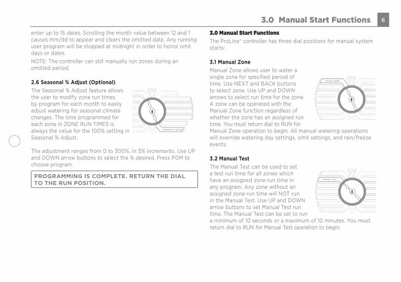
2.6 Seasonal % Adjust (Optional)The Seasonal % Adjust feature allows the user to modify zone run times by program for each month to easily adjust watering for seasonal climate changes. The time programmed for each zone in ZONE RUN TIMES is always the value for the 100% setting in Seasonal % Adjust. The adjustment ranges from 0 to 300%, in 5% increments. Use UP and DOWN arrow buttons to select the % desired. Press PGM to choose program.
PROGRAMMING IS COMPLETE. RETURN THE DIAL TO THE RUN POSITION.
3.0 Manual Start FunctionsThe ProLine® controller has three dial positions for manual system starts:
3.1 Manual ZoneManual Zone allows user to water a single zone for specified period of time. Use NEXT and BACK buttons to select zone. Use UP and DOWN arrows to select run time for the zone. A zone can be operated with the Manual Zone function regardless of whether the zone has an assigned run time. You must return dial to RUN for Manual Zone operation to begin. All manual watering operations will override watering day settings, omit settings, and rain/freeze events.
3.2 Manual TestThe Manual Test can be used to set a test run time for all zones which have an assigned zone run time in any program. Any zone without an assigned zone run time will NOT run in the Manual Test. Use UP and DOWN arrow buttons to set Manual Test run time. The Manual Test can be set to run a minimum of 10 seconds or a maximum of 10 minutes. You must return dial to RUN for Manual Test operation to begin.
3.0 Manual Start Functions
RUNSYSTEM OFF
CURRENT TIME / DATE
PROGRAM START TIMES
ZONE RUN TIMES
DAYS TO WATER
OMIT TIMES / DAYS
MANUAL ZONE
MANUAL TEST
MANUAL PROGRAM
MULTIMETER
VALVE LOCATOR
SENSOR OPERATION
RUN AND SOAK CYCLESADVANCED
MENU
RUNSYSTEM OFF
CURRENT TIME / DATE
PROGRAM START TIMES
ZONE RUN TIMES
DAYS TO WATER
OMIT TIMES / DAYS
MANUAL ZONE
MANUAL TEST
MANUAL PROGRAM
MULTIMETER
VALVE LOCATOR
SENSOR OPERATION
RUN AND SOAK CYCLESADVANCED
MENU
SEASONAL % ADJUST
SYSTEM OFF
ADVANCEDMENU
RUN
MANUAL PROGRAM
MULTIMETER
VALVE LOCATOR
SENSOR OPERATION
RUN AND SOAK CYCLES
CURRENT TIME / DATE
PROGRAM START TIMES
ZONE RUN TIMES
DAYS TO WATER
OMIT TIMES / DAYS
SEASONAL % ADJUST
MANUAL TEST
SYSTEM OFF
ADVANCEDMENU
RUN
MANUAL PROGRAM
MULTIMETER
VALVE LOCATOR
SENSOR OPERATION
RUN AND SOAK CYCLES
CURRENT TIME / DATE
PROGRAM START TIMES
ZONE RUN TIMES
DAYS TO WATER
OMIT TIMES / DAYS
SEASONAL % ADJUST
MANUAL TEST
MANUAL ZONE
SYSTEM OFF
ADVANCEDMENU
RUN
MANUAL PROGRAM
MULTIMETER
VALVE LOCATOR
SENSOR OPERATION
RUN AND SOAK CYCLES
CURRENT TIME / DATE
PROGRAM START TIMES
ZONE RUN TIMES
DAYS TO WATER
OMIT TIMES / DAYS
SEASONAL % ADJUST
MANUAL ZONE SYSTEM OFF
ADVANCEDMENU
RUN
MANUAL PROGRAM
MULTIMETER
VALVE LOCATOR
SENSOR OPERATION
RUN AND SOAK CYCLES
CURRENT TIME / DATE
PROGRAM START TIMES
ZONE RUN TIMES
DAYS TO WATER
OMIT TIMES / DAYS
SEASONAL % ADJUST
MANUAL ZONE
MANUAL TEST

7
Manual Test will detect open circuits (less than 30 mA draw) on any used zone or a short on any output (master valve or zone). If the display indicates FAULT while running a Manual Test, refer to Advanced Menu to identify the FAULT.
3.3 Manual Program Manual Program allows you to start any program set up in the controller; A, B, C or D. Zones will run for the time set at Zone Run Times for the selected program.• Turn dial to Manual Program. OFF
will appear in the screen. • Use UP and DOWN arrows to select
the program you want to run (PROG A, B, C or D)
• Return dial to RUN. Program will commence watering. At the end of the manual watering cycle, the controller will return to automatic RUN mode.
1 amp = 1,000 milliamps
0.250 A 250 mA
0.500 A 500 mA
0.750 A 750 mA
1.000 A 1,000 mA
4.0 System Diagnostics and Eco FeaturesYour ProLine® controller has both System Diagnostic and Eco Friendly dial positions:
4.1 MultimeterOutputsTurn dial to Multimeter position. Outputs will appear on the screen. Push the NEXT button to check the amperage output for the MV (master valve) and each numbered zone. Typical range is .150 to .350 Amps. Anything less than .03 Amps is considered an open circuit for that zone. If an Open or Short fault message appears during this testing, the fault indication is identifying the electrical problem (short circuit or open circuit) with the zone. Note: If you have more than one valve on a zone, the ProLine® controller will measure total current for the combined valves.BatteryTo check the battery voltage level (applies to PL1600 & PL4800 only), turn dial to Multimeter. Outputs will appear on the screen. Push the Adjust Value up arrow button one time. Battery will appear on the screen. Push the Next button once to read battery voltage status. A minimum of 7.5V is required to operate the screen. ProLine® controllers use a Real Time Calendar Clock instead of a backup battery to maintain correct time during a power outage. A battery is only necessary for viewing the screen and programming when the panel is removed from the housing.
4.0 System Diagnostics and Eco Features
SYSTEM OFF
ADVANCEDMENU
RUN
MULTIMETER
VALVE LOCATOR
SENSOR OPERATION
RUN AND SOAK CYCLES
CURRENT TIME / DATE
PROGRAM START TIMES
ZONE RUN TIMES
DAYS TO WATER
OMIT TIMES / DAYS
SEASONAL % ADJUST
MANUAL ZONE
MANUAL TEST
SYSTEM OFF
ADVANCEDMENU
RUN
MULTIMETER
VALVE LOCATOR
SENSOR OPERATION
RUN AND SOAK CYCLES
CURRENT TIME / DATE
PROGRAM START TIMES
ZONE RUN TIMES
DAYS TO WATER
OMIT TIMES / DAYS
SEASONAL % ADJUST
MANUAL ZONE
MANUAL TEST
MANUAL PROGRAM
RUNSYSTEM OFF
VALVE LOCATOR
SENSOR OPERATION
RUN AND SOAK CYCLES
CURRENT TIME / DATE
PROGRAM START TIMES
ZONE RUN TIMES
DAYS TO WATER
OMIT TIMES / DAYS
SEASONAL % ADJUSTADVANCED
MENU
MANUAL ZONE
MANUAL TEST
MANUAL PROGRAM
RUNSYSTEM OFF
VALVE LOCATOR
SENSOR OPERATION
RUN AND SOAK CYCLES
CURRENT TIME / DATE
PROGRAM START TIMES
ZONE RUN TIMES
DAYS TO WATER
OMIT TIMES / DAYS
SEASONAL % ADJUSTADVANCED
MENU
MANUAL ZONE
MANUAL TEST
MANUAL PROGRAM
MULTIMETER

8
24V PowerTo check transformer voltage, turn dial to Multimeter. Outputs will appear in the screen. Press Adjust Value up arrow button until you get 24V Power. Push Next button once to read output voltage for the transformer. Normal reading is 24 to 30 volts AC.
4.2 Valve LocatorThis patented feature will rapidly cycle power to a solenoid valve to create a “chatter” for a selected valve as a convenient method of locating buried valves. Use NEXT button to scroll to the valve you want to “chatter”. You will need to turn off the main water valve for the Valve Locator feature to work properly.Note: As many valves are located underground, the sound may be dampened. If this is the case, you will need to listen carefully for the valve “chatter”.
4.3 Sensor OperationSensorThe Sensor Operation function is used to omit selected zones from sensor shutdown during rain or freeze conditions. Factory default is all zones included for sensor shutdown. If you have zones like potted plants under cover, you may wish to omit those zones from sensor shutdown. Turn dial to Sensor Operation. Push NEXT button to view SENSOR and NEXT again to view first zone. Use up or down Adjust Value buttons to select sensor ON or OFF for the zone. OFF means the zone WILL WATER during sensor shutdown.RFSProLine® controllers can utilize the RFS Sensor for Rain and Freeze Shutdown. This means that you can take advantage of differentiating between Rain and Freeze events, unlike standard sensors on the market. Another powerful feature is the ability to extend a Rain shutdown event beyond the short time the Rain sensor is actually wet, saving even more water.Press the NEXT button at SLW to display DELAY. Press NEXT again to display the number of hours the controller will suspend irrigation after the Rain sensor has dried out. The factory default is 48 hours.RAIN and FREEZE selections work the same as SENSOR described above, however allow you to differentiate between rain and freeze events. For example, you may want your potted plants to irrigate during rain but not during a freeze.
4.0 System Diagnostic and Eco Features
Note: In order for the locator feature to work, you will need to turn off the system water pressure at the manual cut-off valve or water meter. Pressure must be off while attempting
to “chatter” a valve. The ProLine® controller will automatically sequence "chatter" to each valve including the master valve(s).
RUNSYSTEM OFF
SENSOR OPERATION
RUN AND SOAK CYCLES
CURRENT TIME / DATE
PROGRAM START TIMES
ZONE RUN TIMES
DAYS TO WATER
OMIT TIMES / DAYS
SEASONAL % ADJUSTADVANCED
MENU
MANUAL ZONE
MANUAL TEST
MANUAL PROGRAM
MULTIMETER
RUNSYSTEM OFF
SENSOR OPERATION
RUN AND SOAK CYCLES
CURRENT TIME / DATE
PROGRAM START TIMES
ZONE RUN TIMES
DAYS TO WATER
OMIT TIMES / DAYS
SEASONAL % ADJUSTADVANCED
MENU
MANUAL ZONE
MANUAL TEST
MANUAL PROGRAM
MULTIMETER
VALVE LOCATOR
RUNSYSTEM OFF
RUN AND SOAK CYCLES
CURRENT TIME / DATE
PROGRAM START TIMES
ZONE RUN TIMES
DAYS TO WATER
OMIT TIMES / DAYS
SEASONAL % ADJUSTADVANCED
MENU
MANUAL ZONE
MANUAL TEST
MANUAL PROGRAM
MULTIMETER
VALVE LOCATOR
RUNSYSTEM OFF
RUN AND SOAK CYCLES
CURRENT TIME / DATE
PROGRAM START TIMES
ZONE RUN TIMES
DAYS TO WATER
OMIT TIMES / DAYS
SEASONAL % ADJUSTADVANCED
MENU
MANUAL ZONE
MANUAL TEST
MANUAL PROGRAM
MULTIMETER
VALVE LOCATOR
SENSOR OPERATION

9
4.4 Run and Soak CyclesThe Run and Soak Cycles setting allows you to set a variable run and pause time for each program. Run/Soak cycles are used to break up long run times which can often cause wasteful runoff. This feature is especially useful in areas that have slopes or dense soil. Turn dial to Run and Soak Cycles. Use PGM button to select the program you want. Press the NEXT button when the display reads RUN to set the run time. Use the UP and DOWN buttons to enter the amount of time you would like system to run before pausing. If you are unsure of how long the system should run before pausing use the Manual Program feature to run the program until the soil becomes saturated and run off begins forming. Selectable times for RUN range from OFF to 30 minutes, adjustable in 1 minute increments. The default for the controller is OFF. Once you have entered in the run time desired, press the BACK button. The value flashing will be saved. After the RUN time has been configured, press the UP or DOWN button so that the display reads SOAK. Press the NEXT button to alter the SOAK time. Use the UP and DOWN buttons to adjust the soak time. Selectable times for soaking range from OFF to 2 hours, adjustable in 1 minute increments. A good rule of thumb for setting the soak time is twice the run time. The default setting for SOAK is OFF.Note: Adjusting the Run and Soak Cycles setting will increase the total amount of elapsed time before a program is complete. For example, a zone run time is programmed to run for 15 minutes and set to Run/Soak cycle is set to run for 5 minutes and soak for 10 minutes. The system will irrigate for 5 minutes and then pause for 10 three times so that the system was irrigating for a total of 15 minutes. However, the total time elapsed will be 45 minutes, due to the 3, 10-minute pauses (30 minutes) required.
4.0 System Diagnostic and Eco Features
10
5.0 Advanced Menu
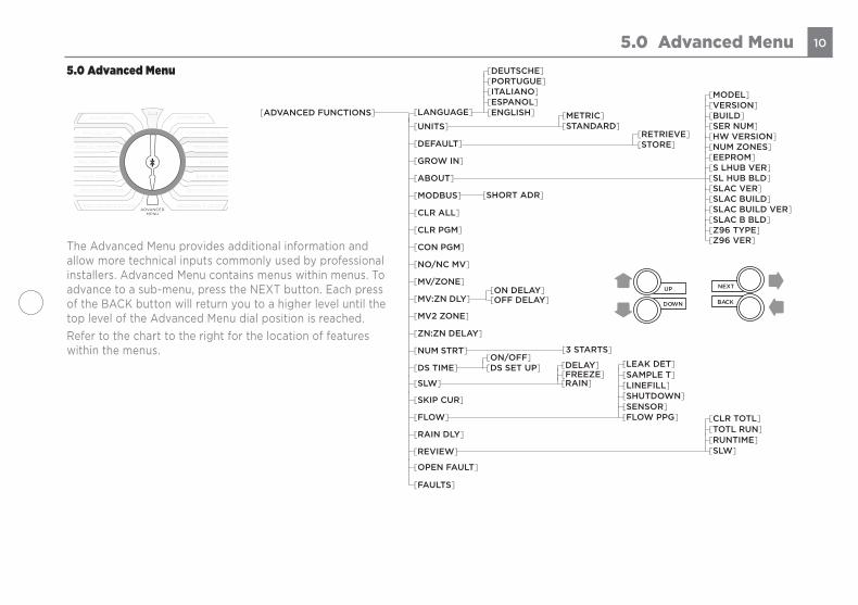
The Advanced Menu provides additional information and allow more technical inputs commonly used by professional installers. Advanced Menu contains menus within menus. To advance to a sub-menu, press the NEXT button. Each press of the BACK button will return you to a higher level until the top level of the Advanced Menu dial position is reached.Refer to the chart to the right for the location of features within the menus.
5.0 Advanced Menu
RUNSYSTEM OFF
CURRENT TIME / DATE
PROGRAM START TIMES
ZONE RUN TIMES
DAYS TO WATER
OMIT TIMES / DAYS
SEASONAL % ADJUST
MANUAL ZONE
MANUAL TEST
MANUAL PROGRAM
MULTIMETER
VALVE LOCATOR
SENSOR OPERATION
RUN AND SOAK CYCLES
RUNSYSTEM OFF
CURRENT TIME / DATE
PROGRAM START TIMES
ZONE RUN TIMES
DAYS TO WATER
OMIT TIMES / DAYS
SEASONAL % ADJUST
MANUAL ZONE
MANUAL TEST
MANUAL PROGRAM
MULTIMETER
VALVE LOCATOR
SENSOR OPERATION
RUN AND SOAK CYCLESADVANCED
MENU
[ADVANCED FUNCTIONS]
[UNITS]
[DEFAULT]
[GROW IN]
[ABOUT]
[MODBUS]
[CLR ALL]
[CLR PGM]
[CON PGM]
[NO/NC MV]
[MV/ZONE]
[MV:ZN DLY]
[MV2 ZONE]
[NUM STRT]
[DS TIME]
[FLOW]
[SLW]
[RAIN DLY]
[SKIP CUR]
[3 STARTS]
[METRIC][STANDARD]
[ZN:ZN DELAY]
[ON DELAY][OFF DELAY]
[SHORT ADR]
[RETRIEVE][STORE]
[DEUTSCHE][PORTUGUE][ITALIANO][ESPANOL][ENGLISH]
[VERSION][BUILD][SER NUM]
[MODEL]
[Z96 VER]
[HW VERSION][NUM ZONES][EEPROM][S LHUB VER][SL HUB BLD][SLAC VER][SLAC BUILD][SLAC BUILD VER][SLAC B BLD][Z96 TYPE]
[SAMPLE T][LINEFILL][SHUTDOWN]
[LEAK DET]
[FLOW PPG]
[FREEZE][DELAY]
[RAIN]
[ON/OFF][DS SET UP]
[REVIEW]
[CLR TOTL][TOTL RUN][RUNTIME][SLW]
UP
DOWN
NEXT
BACK
[LANGUAGE]
[SENSOR]
[FAULTS]
[OPEN FAULT]
11
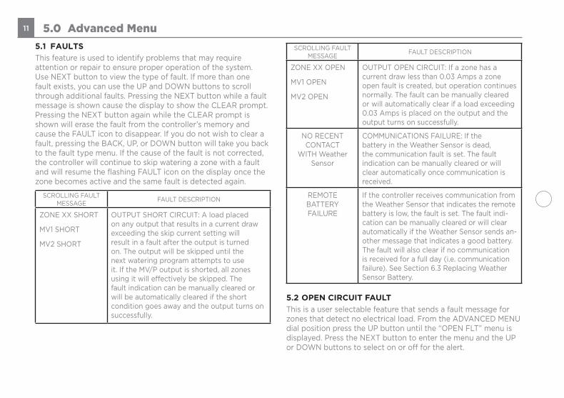
5.1 FAULTSThis feature is used to identify problems that may require attention or repair to ensure proper operation of the system. Use NEXT button to view the type of fault. If more than one fault exists, you can use the UP and DOWN buttons to scroll through additional faults. Pressing the NEXT button while a fault message is shown cause the display to show the CLEAR prompt. Pressing the NEXT button again while the CLEAR prompt is shown will erase the fault from the controller’s memory and cause the FAULT icon to disappear. If you do not wish to clear a fault, pressing the BACK, UP, or DOWN button will take you back to the fault type menu. If the cause of the fault is not corrected, the controller will continue to skip watering a zone with a fault and will resume the flashing FAULT icon on the display once the zone becomes active and the same fault is detected again.
SCROLLING FAULT MESSAGE FAULT DESCRIPTION
ZONE XX SHORT
MV1 SHORT
MV2 SHORT
OUTPUT SHORT CIRCUIT: A load placed on any output that results in a current draw exceeding the skip current setting will result in a fault after the output is turned on. The output will be skipped until the next watering program attempts to use it. If the MV/P output is shorted, all zones using it will effectively be skipped. The fault indication can be manually cleared or will be automatically cleared if the short condition goes away and the output turns on successfully.
SCROLLING FAULT MESSAGE FAULT DESCRIPTION
ZONE XX OPEN
MV1 OPEN
MV2 OPEN
OUTPUT OPEN CIRCUIT: If a zone has a current draw less than 0.03 Amps a zone open fault is created, but operation continues normally. The fault can be manually cleared or will automatically clear if a load exceeding 0.03 Amps is placed on the output and the output turns on successfully.
NO RECENTCONTACT
WITH Weather Sensor
COMMUNICATIONS FAILURE: If the battery in the Weather Sensor is dead, the communication fault is set. The fault indication can be manually cleared or will clear automatically once communication is received.
REMOTE BATTERY FAILURE
If the controller receives communication from the Weather Sensor that indicates the remote battery is low, the fault is set. The fault indi-cation can be manually cleared or will clear automatically if the Weather Sensor sends an-other message that indicates a good battery. The fault will also clear if no communication is received for a full day (i.e. communication failure). See Section 6.3 Replacing Weather Sensor Battery.
5.2 OPEN CIRCUIT FAULTThis is a user selectable feature that sends a fault message for zones that detect no electrical load. From the ADVANCED MENU dial position press the UP button until the “OPEN FLT” menu is displayed. Press the NEXT button to enter the menu and the UP or DOWN buttons to select on or off for the alert.
5.0 Advanced Menu

12
5.3 LANGUAGEIn addition to being able to change the controller’s menu languages by using the LANGUAGE button, they can be set in this menu. The language options in this menu are the same as those provided by the LANGUAGE button. The available languages are English, Spanish (Español), Italian (Italiano), Portuguese (Português), or German (Deutsche). Press the BACK button when the display reads your desired selection.
5.4 UNITS This setting allows for you to choose either STANDARD (Unit-ed States customary units) or METRIC. Press the BACK button when the display reads your desired selection.
5.5 DEFAULTThis is an optional function that allows the user to store a program that can be retrieved later if it is inadvertently deleted or changed. Once the controller has been programmed, go to Advanced Menu and select DEFAULT. Press NEXT and STORE will appear on the display. Pressing NEXT one more time will show the CONFIRM prompt; press NEXT to proceed or BACK to exit the prompt. Pressing NEXT at the CONFIRM prompt will cause the display to read COMPLETE to show that you have successfully stored the program. Press the BACK button any time after the display shows COMPLETE to return to the advanced menu.If the controller has had the operating program changed and you want to return to the stored program, go to DEFAULT, press NEXT and then of the arrow buttons. The display will show RETRIEVE. Pressing NEXT one more time will show the CONFIRM prompt; press NEXT to proceed or BACK to exit the prompt. Pressing NEXT at the CONFIRM prompt will cause the display to read COMPLETE to show that you have successfully
restored the program default program to the operating program. Press the BACK button any time after the display shows COMPLETE to return to the advanced menu.
5.6 GROW-INGrow In allows you to set up a new landscape grow-in water-ing program that will automatically expire after a set number of days that you select. At the end of your selected grow-in period, the controller will automatically retrieve your long-term watering program to avoid the necessity of having to return to the controller. Step 1: Set up your long-term watering program.Step 2: Go to Advanced Menu and select DEFAULT. Press NEXT and STORE will appear on the display. Press the NEXT button and the screen will display CONFIRM, press the NEXT button once more and within a few seconds the display will read COMPLETE to confirm that you have successfully stored your program.Step 3: Set up your temporary Grow-In program.Step 4: Go to Advanced Menu and select GROW IN. Press NEXT once to view default days for grow in. Use Adjust Value buttons to select 1 to 99 days for the grow in period. At the end of your grow in, the controller will automatically retrieve the DEFAULT program stored in Step 2. Return dial to Run.
5.7 ABOUTProvides information on software version in the ProLine® controller.
5.7.1 MODELDisplays the model name of the controller.
5.0 Advanced Menu

13
5.7.2 VERSIONDisplays current version of the controller’s software.
5.7.3 BUILDDisplays current build version of the controller.
5.7.4 SER NUMDisplays the controller’s serial number.
5.7.5 HW VERSIONDisplays the hardware version of the controller.
5.7.6 NUM ZONESDisplays the maximum number of zones that can be created.
5.7.7 EEPROMDisplays the amount of EEPROM available in bytes.
5.7.8 SLHUB VERDisplays the version of the RFS weather sensor. NI is show if this is not installed.
5.7.9 SLHUB BLDDisplays the build version of the RFS weather sensor. NI is show if this is not installed.
5.7.10 SLAC B VERDisplays the version of the aircard. NI is show if this is not installed.
5.7.11 SLAC B BLDDisplays the build version of the aircard. NI is show if this is not installed.
5.7.12 Z96 TYPEDisplays the decoder manager type if SmartWire equipped.5.7.13 Z96 VERSThe display reads Z96 VERS here.
5.8 MODBUS
5.8.1 SHORT ADDThis displays a static address along with a user programmable address to integrate with third party software.
5.9 CLR ALLThis feature is similar to CLR PGM except that it clears all user programmed data for all four programs and returns most Advanced Menu changes to factory defaults. Turn the dial to Advanced Menu and use and use the UP button to navigate to CLR ALL. Press the NEXT button and the screen will display CONFIRM. Press the NEXT button once more and the display will show CLEARING when finished to confirm that all programs have been cleared.
5.0 Advanced Menu

14
5.10 CLR PGMThis feature allows the user to clear all programmed values specific to a selected program. All zone run times and daily start times will be set to OFF; watering days will default to Days of the Week (all on); Season % will equal 100% for all months and Run/Soak will be OFF. Omit times/days are not reset when clearing a program. Turn the dial to Advanced Menu and use the UP button to navigate to CLR PGM. Press the NEXT button and the display will read CONFIRM. Use the PGM button to select the program (A, B, C or D) to be cleared. Press the NEXT button and when the selected program has been cleared from the panel the display will read COMPLETE. Repeat these steps to clear each individual program to be reset.
5.11 CON PGMSelect the ability to run 1, 2,3, or all 4 programs simultaneously. Default is two simultaneous programs. Programs will prioritize with the order of priority being: A, B, C, D.
5.12 NC/NO MVEnter this menu to select between normally open or normally closed master valves for MV1 and MV2.
5.13 MV/ZONEThis feature allows you to select which master valve(s) to be assigned for each zone operation. The default is MV1. The other options are MV2, BOTH, OFF.Caution: If an unused zone is turned on and activates a pump start relay, the pump may overheat or cause a pipe to burst. To prevent operating a pump with no flow (dead heading), make sure all unused zones are set to OFF.
5.14 MV/ZN DLY This function allows the user to set a delay time between the opening of the master valve and the opening of the first zone valve as well as a delay between the closing of the last zone valve and the closing of the master valve.Use the NEXT button to enter menu. Select setting for the ON Delay or OFF Delay by pressing NEXT. Use UP and DOWN buttons to select delay time. Use arrow buttons to set ON Delay time from 0 seconds to 1 minute in 1 second increments. OFF Delay can be set from 0 seconds to 3 minutes in 1 second increments.
5.15 MV2 ZONEA second master valve circuit can be enabled in this menu by designating a zone valve to be MV2
5.7.5.16 ZN/ZN DLYThis function allows user to set delay times between zone starts for use in systems with slow closing valves or pump systems that are operating near maximum flow or have slow well recovery. UseUP and DOWN buttons to change value. Adjustable in one-minute increments from 0 (the controller default setting) to 30 minutes; adjustable in 10 minute increments from 30 minutes to 3 hours.
Note: The Master Valve/Pump Start circuit will operate 2 seconds prior to program operation and 5 seconds after program completion.
This On/Off time delay aids zone valve operation and prevents unnecessary cycling of the pump.
5.0 Advanced Menu

15
5.17 NUM STARTThis feature allows you to select the number of Watering Program Start Times that you want to appear at Program Start Times on the dial. The default number of start times shown is 3. To select 1 to 8 start times, go to Advanced Functions, NUM STRT. Press Next to view the default of 3 start times. Scroll the UP/DOWN buttons to select 1 to 8 start times to be visible on the dial. Return the dial to Run.
5.18 DS TIMEYour SmartLine® controller can automatically adjust the time for daylight saving time (DST). The factory default setting is OFF and has been preset for the current USA schedule. To turn DST adjust ON, press the next button at DS TIME, the NEXT button at ON/OFF then select ON.The DS Time feature can be customized to match any international DST schedule. Press the NEXT button at DS TIME in advanced functions. Select DS SETUP and press the NEXT button again. You will be prompted to enter the START schedule (time of day is moved ahead 1 hour per START schedule), and the STOP schedule (time of day is moved back 1 hour per STOP schedule). DST start and stop are formatted with the the Week (first, second, third, last), the Day (Sun-Sat) and the Month (Jan-Dec). All DS Time adjustments are made at 2 am. To return the DS Time schedule back to the USA factory default, use the US DEFLT option.
5.18.1 DST ON/OFFIf you would like for your controller to automatically set the time of day on the occurrence of Daylight Saving Time, make sure it is turned on in this menu
5.18.2 DS SETUPYour controller is programmed with the a default of starting Daylight Saving Time starting on the second Sunday in March and ending on the first Sunday in November. If you would like to adjust these settings, you may do so in this menu.
5.19 RUN/SOAKThe purpose of Run/Soak is to break up long run times that often cause wasteful runoff. The Run/Soak is programmable for each program if you are using the BASIC watering mode. Note: If you are using SMART, these inputs are not used since the Run/Soak period is automatically calculated.Turn the dial to Advanced Menu and use the UP button to navigate to RUN/SOAK. Press the NEXT button and the screen will display RUN, now press the PGM button to select the program you wish to set the RUN feature. After the program has been selected, press the NEXT button and then using the UP or the DOWN button adjust the RUN value. **NOTE: the RUN time can be set from OFF to 30 minutes (SmartLine®TM controller default is OFF). Once completed, press the BACK button and the screen will again display RUN, now press the UP or the DOWN button and the screen will display SOAK. Press the NEXT button to enter the SOAK feature and then using the UP or the DOWN button adjust the SOAK value. **Note: the SOAK time can be set f from OFF to 2 hours in one-minute increments. Repeat these steps for adjusting multiple programs within the panel.
5.20 SENSORSensor is an ON/OFF toggle to override the SEN terminals rain/freeze functions on selected zones. Factory default is ON.
5.0 Advanced Menu

16
5.21 FLOW
NOTE: Flow menus require the addition of a SmartLink AirCard with FLOW capabilities.
5.21.1 HIGH PKShows the highest flow value for each individual zone, can scroll through each zone for a 7-day history.
5.21.2 CLR FLOWClears All flow data from the controller.5.21.3 SETTINGSAllows the user to set Flow parameters. 5.21.3.1 FLOW PPG
A settable value that lets the controller know how many . .pulses to expect per gallon.
5.21.3.2 SENSORLets the user select a custom sensor or one of our preset flow sensor types.
5.21.3.3 SHUTDOWNAllows the user to select if the controller should shut down operation per zone or by system.
5.21.3.4 LINEFILLThe time it takes for the system to purge air and completely fill the piping with water.
5.21.3.5 SAMPLE T How often the controller reads flow pulses from the Aircard. 5.21.3.6 LEAK DET
A settable value that determines when the controller will produce a Leak Detect fault.
5.21.3.7 LOW LMTThe lowest flow value the controller can sense without producing a fault.
5.21.3.8 HIGH LMTThe highest flow value the controller can sense without producing a fault.
5.21.4 TOT FLOWShows the daily total flow for each zone. Can scroll through each zone for a 7-day history.
5.21.5 LOW PKShows the lowest flow value for each individual zone, can scroll through each zone for a 7-day history.
5.22 SLW
5.22.1 RAINThe rain selection is on/off toggle to override the SLW sensor feature for selected zones. Factory default is ON for all zones.
5.22.2 FREEZEThe freeze selection is on/off toggle to override the SLW freeze sensor feature for selected zones. Factory default is ON for all zones.
5.22.3 DELAYThis feature allows the user to adjust the factory set 48 hour watering delay that will occur after a rain event shutdown if you are using an SLW Weather Sensor for SMART Watering. To eliminate the delay or to reduce or increase the factory default hours, turn the dial to Advanced Menu and use an arrow button to select SLW DLY. Press the NEXT button and 48 hours will show in the display. Use the UP and DOWN buttons to eliminate
5.0 Advanced Menu

17
the delay or to select a different number of hours (0–99 hours). Note: The SLW DLY begins after the SLW rain sensor has reset following a rain event. Accumulation of new water deficits will not begin until after the SLW DLY has cleared.
5.23 RAIN DLYThe rain delay feature allows user to globally suspend watering operations for all programs for a selected number of days.Use UP or DOWN buttons to select 1 to 14 days for watering suspension. The watering blackout will automatically be cleared from the SmartLine® controller after the assigned days have expired and watering will resume at the next available start time. SMART watering deficits will reset at zero and will not resume accumulation until the delay has ended.
5.24 SKIP CUR You can increase the skip circuit threshold here. Some acces-sory, like pump start relays, In rush currents exceed the factory setting of 1.0 Amp for SL800 and 1.5A for all other controllers.
5.25 REVIEWTurn dial to Advanced Menu. Push NEXT button to access review functions. Use UP/DOWN buttons to select review functions you wish to view.
5.25.1 SLW 5.25.2.1 LASTCOM
This feature records time elapsed since last successful communication between the weather station and control panel.
5.25.2.2 BATTERYCheck the battery status in your wireless weather station here.
5.25.2 TOTL RUNTOTL RUN is the total run time for each zone since the date shown (default date in the SmartLine® controller is January 1, 2000 shown as 01/01/00). You can review TOTL RUN for either the BASIC or SMART modes. After you select TOTL RUN with the UP button, use NEXT to view the date when TOTL RUN accumulation began. Use NEXT again to view the total run times for each zone.You can use the NEXT and BACK buttons to move through the zones. After you go through all the zone positions, use the NEXT button one more time to take you back to the TOTL RUN screen.
5.25.4 CLR TOTL3CLR TOTL is used to clear and reset the total run time for each zone shown in the TOTL RUN menu.From the CLR TOTL menu, press NEXT and the display will show KEEP. If you want to clear the TOTL RUN time and reset the accumulation date, press either the UP or DOWN button to display CLEAR. With CLEAR showing in the display, either press NEXT or BACK or turn the dial to complete the clearing and resetting. This feature will stop accumulations on a zone after 255 hours of cumulative zone run time.
5.0 Advanced Menu

185.0 Advanced Menu
6.0 Troubleshooting6.1 Total Reset Procedure For The ProLine® controllerA total reset will clear all programming data in the ProLine® controller. All settings will return to factory defaults. For all ProLine® models except PL800:• Turn dial to Advanced Menu.• While pressing the UP arrow button, use an open paper clip or
ballpoint pen to push in the Reset switch located on the back of the operating panel. Release the reset button while continuing to press and hold the UP arrow button.
• Once the display shows CLEARING, release the UP arrow button.• Reprogram ProLine® controller.For the PL800:• Unplug the power supply on the side of the PL800.• Turn dial to Advanced Menu.• While continually holding down on the UP arrow button, reapply
the power connection to the PL800.• The display will read “CLEARING” to verify that the Reset is
complete. Re-enter your controller settings.
6.2 Watering Cycle Pause FunctionsProLine® controllers will “pause” watering cycles in response to certain sensor readings or program settings in the controller. Pauses are a normal function of the controller. If a watering pause occurs, the reason will be shown on the controller’s display. The table below provides a more detailed description of each message.
LANGUAGELED Color
SENSOR LED Color
Display Message Reason
Red Controller dial is set to OFF
Green Red RAIN Rain sensor disks are wet (SLW Only)
Green Red FREEZE Temperature is 37 degrees F or colder (SLW Only)
Green Red SENS Sensor tripped at the SEN terminals
Green Orange RAIN DLY
Irrigation cancelled for additional hours in SLW DLY (SLW Only)
Orange Green Omit-Time
Cycle paused for omit hours set
Orange Green SOAK Zone waiting for soak time out
Orange Green ZONE DLY
Waiting for next zone valve to open
Orange Green PAUSE Waiting for MVP to turn on or off

19 6.0 Troubleshooting6.3 Troubleshooting Guide
Problem Causes Solutions
No Display No power to controller Check power wiring, breaker, and be sure control panel is firmly closed.
No 24V power from transformer
Blown fuse
Replace transformer. Likely power surge damage
Replace fuse with factory replacement. Do Not use a higher value fuse.
Controller Replacement Fuse Part#
PL800-Transformer 120VAC/60Hz 175-091SA
PL800 - Fuse, 1 Amp, Slo-Blo VEF-020SA
PL1600-Series Transformer 120V 170-085SA
PL1600-SL1600 Fuse, 1 Amp, Slo-Blo VEF-032
FAULT icon on display
Shorted or open condition on a zone(s)
Check solenoid(s) and wiring (turn dial to Advanced Menu for fault information in Sec 6.1)
Shorted MV/P Check solenoid(s) and wiring
Display shows zone is running but no sprinklers are operating
Water supply to system is shut OFF
Turn on water supply to system
Valve failure Verify valve operation
Open or disconnected wire Run MANUAL TEST as shown. Verify FAULT icon is shown display. Turn dial to Advanced Menu to determine location of fault
Controller keeps repeating a watering cycle
Extra start times are set at the Program Start Times position on the dial.
Turn dial to Program Start Times. Use NEXT button to view all start times. Hold down on either Arrow button to change the start times or to advance to the OFF position. Each Program will start and run all zones assigned to that program in consecutive order. For most installations, only one start time is needed and the rest should be set to OFF. See Program Start Times, for more information.
Display shows 0 ZONES
Defective module Replace module in zone 1-4 position

206.0 Troubleshooting
Problem Causes Solutions
ProLine® controller does not turn on zone when expected
Sensor jumper is removed and no sensor is connected (Sensor LED is red)
Install jumper wire between SEN terminalsSelect BYPASS mode if desired
Sensor wires have been cut (Sensor LED is red)
Repair wires
Zone comes on at unexpected time
Program daily start times not set properly or multiple start times set. Check Program Start Times
Stacked program has commenced normal operation
Modify settings (such as concurrent program start times, zone run times) to prevent stacking if undesirable
Time of day or date not set properly
Review/set time of day and date
Watering days or omit days/dates not set properly
Review/set watering days or omit days/dates
Run/Soak feature has extended watering window
Normal operation to allow water infiltration and prevent runoff
Controller does not operate zone for expected run time
Pause for Run/Soak in progress. This is normal operation to allow water infiltration and prevent runoff
Module not installed Install module
No initial AC power-up of controller
Connect AC power and close control panel

21 6.0 Troubleshooting
Problem Causes Solutions
ProLine® controller does not turn on zone when expected
Zone set to OFF Set zone run time
Dial set to SYSTEM OFF Position Turn dial to RUN
No zone run time set; no daily start time set
Program zone run time and daily start time
Omit times/days are activated Verify omit times/days
Rain or freeze sensor has stopped watering (Sensor LED is red
Replace sensor if faultySelect BYPASS mode if desiredReset start time to later in the day to avoid early morning freezing temperatures.

www.weathermatic.com
Pro
gra
m A
Pro
gra
m B
Pro
gra
m C
Pro
gra
m D
Wat
erin
g D
ays
Wat
erin
g D
ays
Wat
erin
g D
ays
Wat
erin
g D
ays
Day
s o
f W
eek
Day
s o
f W
eek
Day
s o
f W
eek
Day
s o
f W
eek
SM
TW
TF
SS
MT
WT
FS
SM
TW
TF
SS
MT
WT
FS
O
dd
Eve
n
Od
d
Eve
n
Od
d
Eve
n
Od
d
Eve
n
Inte
rval
(Ev
ery
____
day
sIn
terv
al (
Ever
y __
__ d
ays
Inte
rval
(Ev
ery
____
day
sIn
terv
al (
Ever
y __
__ d
ays
Pro
gra
m S
tart
Tim
esP
rog
ram
Sta
rt T
imes
Pro
gra
m S
tart
Tim
esP
rog
ram
Sta
rt T
imes
15
15
15
15
26
26
26
26
37
37
37
37
48
48
48
48
Om
it D
ays/
Dat
e/Ti
mes
Day
s:D
ates
:
Tim
es:
Fro
m >
To<

Basic W
atering S
chedule
Zo
neLo
cation
Pro
gram
AP
rog
ram B
Pro
gram
CP
rog
ram D
Zo
ne Run Tim
eZ
one R
un Time
Zo
ne Run Tim
eZ
one R
un Time
123456789101112131415161718192021
222324
Seaso
nal % A
djust
PG
MJan
FebM
arA
pr
May
JunJul
Aug
Sept
Oct
Nov
Dec
A%
%%
%%
%%
%%
%%
%
B%
%%
%%
%%
%%
%%
%
C%
%%
%%
%%
%%
%%
%
D%
%%
%%
%%
%%
%%
%

www.weathermatic.com
Bas
ic W
ater
ing
Sch
edul
eZ
one
Loca
tio
nP
rog
ram
AP
rog
ram
BP
rog
ram
CP
rog
ram
DZ
one
Run
Tim
eZ
one
Run
Tim
eZ
one
Run
Tim
eZ
one
Run
Tim
e
25 26 27 28 29 30 31 32 33 34 35 36 37 38 39 40 41
42
43
44
45
46
47
48


www.weathermatic.com

www.weathermatic.com
ADG51_revA