Embed Size (px)
Citation preview

Overview of Headphones
Rytis StasiunasAalto Universtiy
Electronics engineering, Bachelor
1 Introduction
As Cambridge dictionary defines - Headphones are a device with a part to covereach ear through which you can listen to music, radio broadcasts, etc. withoutother people hearing. Even though the first early ancestors of headphones wereused by telephone operators and were not used for any music related applications,nowadays headphones became a crucial part of the music industry.While headphones function the same way as speakers, the produced output is far toodifferent. While speakers are supposed to generate a powerful sound signal for it tobe audible, headphones only require to generate a weak enough signal which needs toreach the eardrum which is only a few millimeters away. Therefore components usedin headphones are much smaller and most of the time more precise than speakercomponents. Small distance and isolation are the two main contributors to theloudness of the sound even when the signal is relatively weak in comparison toregular speakers. Most headphones even support the full 20 hertz to 20,000 Hzfrequency range. However, not all of them can produce a proper low frequencysignal since it requires to move a large amount of air.The report submitted by Grand View Research, Inc. states that the global earphonesand headphones market is expected to reach 17.55 billion USD by 2022, whichshows, that the demand for new products, better quality and reliability is constantlyincreasing.This paper reviews the overall history headphones, specifies the types of headphonesand their transducers and shows how an isodynamic headphone can be designedand simulated using equivalent electrical components. The simulation results arediscussed and are used to show to importance of proper simulations and parameterchoice.
1

2 History of Headphones
It is rather difficult to determine when the first headphones were developed, becausethere was no strict difference between a speaker near your ear and a single earpiece.It is believed that the first headphones were born in the 1880s, which were a singleearpiece that rested on the user’s shoulder and weighed over 10 pounds. However, asmentioned before, with this weigh it is more likely that this earpiece can be definedas a boombox on your shoulder rather than a headphone.In 1910 US Government bureau, Radio Division received a letter from NathanielBaldwin. The writer, Mr. Baldwin stated that he was sending a pair of telephones,which he had patented, and requested that they be tested [2]. He wrote that theyhad a resistance of about 2,000 ohms, which he understood was standard for Navyheadsets [2]. As stated in the book, this was the beginning of low weight, adequatequality headphones with stable impedance. With the help of the Wireless SpecialtyApparatus Co. these headphones were manufactured not only for the US Navy, butalso for the civilian market.The first dynamic headphones that hit the market were Beyerdynamic DT-48. Theyare demonstrated in Fig. 1.
Figure 1: The historical Beyerdynamic DT 48.https://beyerdynamic.com
This was an important milestone in the history of headphones since even now, dy-namic headphones are the most popular type on the market. Another mentionworthy creation were Koss SP-3, the first stereo headphones which were released in1958. Due to this product Fig. 2 Koss dominated the industry for a few decades.
1979 was the year, when Sony showed that the headphones can and had to portable.This year is the release of Sony Walkman series were MDR-3L2 headphones wereincluded.
2

Figure 2: SP/3 The World’s First Koss Stereophonehttps://www.koss.com/history
The 80’s and 90’s brought a bunch of solutions from earbuds and in-ear headphonesto neckband headphones which lost their popularity quite fast while in-ear head-phones and earbuds are one of the most popular types nowadays. At the beginningof a new century, Bose presented their QuietComfort line which came with activenoise-cancelling technology. Even though the concept itself was not new to theworld, although not too many products were available on the market.One of the biggest game changers in the music universe was the release of iPod. Since2001 it became common to people with a white cord running from their pocket totheir ears. From the release up to today over 300 million iPods have been sold andobviously the same amount of earbuds as well. Throughout the time after differentdesigns and types flooded the market and nowadays users can choose from a varietyof different headphones with different price ranges, quality and additional featureswhich shows, that even this invention comes from the past, the relevance of it stayson and increases over-time.
3 Headphone types
Nowadays headphones can come in many sizes and shapes to best fit the userspreferred experiences. Their appearance affects the balance between portability andfidelity. In general, headphone can be divided into four different types:
3.1 Circum-aural headphones
Over-ear headphones, full size headphones or circum-aural headphones have elipsoidor circular earpads that encompass the ear. Usually considered the best headphonesfor sound quality. Circumaural headphones are characterized by a relatively largecoupling volume in excess of 30 cubic centimeters, and an inner diameter of the
3
cushions of at least 55 mm [1]. Due to complete surrounding of the ear, theseheadphones can be designed to passively attenuate as much outer noise as possible.The main drawback comes from their size, which may result in them being heavyand uncomfortable to the user. Usually their used by drummers or in the recordingstudios.
3.2 Supra-aural headphones
On-ear or supra-aural headphones are similar in design to over-ear models, thoughthe cushions sit on the outer ear rather than enclosing the ears. Generally, over-earmodels deliver adequate sound quality, but with less bass response compared toover-ear models. Even though this type weighs less than over-ear they can still leadto user discomfort due to pressure on the ear itself.Both supra-aural and circum-aural headphones can be closed-back, semi-open oropen-back. The open-back headphones gives a more natural, ambient sound whileclosed-back headphones produce a stronger bass response and better attenuatesambient noise.
3.3 Earphones/earbuds
Earphones are very small headphones that are directly fitted on the outer ear. Thedifference between IEMs (In-ear monitors) are that they are only facing ear canal,but are not inserted into it. Even though earphones may be considered as thecheapest type of headphones, they are usually not too comfortable and provideclose to no audio isolation. They are the most common types of headphones to befound included with MP3 players or other music devices and phones.
3.4 Intra-aural headphones
In-ear headphones/monitors are small headphones that are directly inserted in earcanal. Most models include silicone or foam tips in multiple sizes which gives asecure fit and proper ambient noise isolation. Due to fully blocking the ear canal,they are considered the best noise-cancelling headphones. IEMs can be consideredas better quality in-ear headphones. Usually they come with multiple drivers andare used by audio engineers, audiophiles and musicians.
4

4 Types of Transducers
While headphone types are an important aspect for the listener and overall head-phone experience, the main part of the headphone is its transducer. Transducersjob is to convert the electrical signal into a sound wave that the ear can understand.Transducers use several technologies which includes manipulation of magnetic, elec-tric or magneto-electric fields to create a sound wave. Even though the first head-phones used only a single type of a transducer to achieve its goal, nowadays multipletypes of transducers can be used to achieve even better results, however, badly de-signed quad-driver headphones can sound far worse than a single driver headphones.Currently there are quite a few types of transducers on the market and even moreare developed, most of them can be defined as those, mentioned below:
4.1 Dynamic transducers
Dynamic or moving-coil transducers are the most common transducers on the mar-ket due to its low manufacturing price. The transducer consists of three parts: amagnetic element which creates a static magnetic field, a voice coil and a diaphragmwhich is attached to the voice coil. When a current runs through the voice coil itcreates a magnetic field which may be opposite or the same in direction to the sta-tionary magnetic field. Due to varying magnetic field of the coil the coil itself getsattracted or repelled by the magnet which causes the coil and the diaphragm tovibrate. The vibrating diaphragm displaces the air around it, creating sound waves.Obviously, the larger the air displacement, the higher the volume. Because of that,dynamic headphones are great at creating the bass response and transducers arepopularly used in multiple driver headphones to handle the lower frequency sounds.The down-side of the transducer is its non-linearity at high volumes, however thiscan be mitigated by properly designing the transducer and using it in its linearregion.
4.2 Balanced armature transducers
Balanced armature is a sound transducer primarily designed to reduce the stress onthe diaphragm and increase the overall electric efficiency. It consists of a miniaturearmature inside a coil surrounded by two magnets. The basic mechanism of thistransducer is present in Fig. 3.
When current flows through the coil, it magnetizes the armature which pivots to-wards one or the other magnet. This pivoting movement causes the movement of thediaphragm which produces the sound. The term ”balanced” comes from the fact,that when no force is applied to the armature it stays at the exactly same distancefrom both magnets, hence it is balanced. The common practice is to use this typeof transducers for certain frequency range to achieve better overall response. As
5

Figure 3: Mechanism of a balanced armature transducer [1]
mentioned above, balanced armature transducers are commonly used with dynamictransducer since they commonly lack proper bass response. The advantages of thistype of transducers are more detailed sound and better treble performance thandynamic transducers, however, they lose in manufacturing price and complexity aswell as bass response.
4.3 Electrostatic transducer
While other types of transducers use electromagnetic properties to create sound, asthe name implies, this type of transducer uses static electricity as its main propertyto produce mechanical waves. Transducer consists of a thin electrically chargeddiaphragm which is suspended between two perforated electrodes Fig. 4.
Figure 4: Electrostatic transducer diagram [1]
When an electrical signal is applied to the electrodes it creates an electric field whichattracts the diaphragm to one of the plates. The constant change in the electricfield vibrates the diaphragm which moves the air through the perforated gaps whichresults in a sound wave. The diaphragm is manufactured as light and as flexible aspossible. As mentioned in [4] the wavefront is nearly plane at all frequencies so thatsmall changes of position or distance make little difference to the sound pressure.
6

Additionally, the frequency response of this type of transducer usually extends abovethe audio frequency limit which results in lower distortion throughout full audiorange and more accurate response at higher frequencies which is usually absent atdynamic drivers. The electrostatic principle has inherent advantages which makepossible the construction of loudspeakers with lower coloration, better transientresponse, lower non-linearity distortion, and radiation characteristics more suitablyrelated to room acoustics, than can be achieved using other techniques [1]. However,the manufacturing complexity for this type of transducer reflects on the higherprice of the headphones, furthermore, the headphones are usually pretty large andbulky, since the driver itself is usually made quite large to deliver proper sound.Furthermore, electrostatic drivers require special amplifiers, since voltages up to1kV are required to deflect the membrane. Even though some may think, that thistype of transducer should be unsafe to the user due to high voltages, it is not actuallycorrect, since the isolation and the low amount of current needed for this transducermakes it as safe as possible for usage. All in all, electrostatic transducers may beseen as the best type of transducers for a high-end headphone set, however due toits high price and bulkiness they are not the most preferable pick.
4.4 Planar magnetic transducers
Planar magnetic transducer or also known as orthodynamic (Yamaha) transducer isbased on a similar principle as a dynamic transducer, but instead of the moving-coilthat is affected by magnetic field change the full diaphragm is affected to producesound. In design it is somewhat similar to electrostatic transducers, the diaphragmcontains an embedded wire pattern and is located between two or more permanentmagnets. The current running through the pattern creates a magnetic field whichreacts with the magnetic field of the permanent magnets which induces vibrationsand hence - sound. Since the whole diaphragm has to be evenly vibrated, largermagnets are needed to create the best response Fig. 5.
For this reason, this technology is relatively large in size, compared to moving-coil transducers and also quite expensive. However, this type of transducer createsa high quality sound with close to no distortion and a good transient response.Additionally, bass response is excellent, due to the combination of the large thindiaphragm and strong electromagnetic force leading to the ability to displace alarge amount of air and creating proper low frequency sound wave. Nevertheless,great sound reproduction comes with a few drawbacks. Thin diaphragm has ahigher manufacturing price, also two large magnets are required as well which makesheadphones with this type of transducer relatively heavy and not popular to beused in portable applications, additionally, most transducers require an additionalamplifier due to its high impedance.
7

Figure 5: Planar magnetic transducer (Audeze planar driver unit)
5 Electrical analogies for headphone modeling
In the previous chapters the physical appearance and the type of transducers werediscussed, but the main question comes - how is it possible to model such a com-plicated electromechanical system. According to [1] headphones comprise of mainlythese building blocks:
5.1 Cavities
Cavities are modelled as a single capacitor connected in parallel to the system andadditonally one of the nodes is always grounded. Cavity is defined by its volumeand the formula presented in the Fig. 6 defines the capacitance.
5.2 Acoustical bottlenecks - holes and slits
Due to simple manufacturing, porous elements like holes and slits are used for res-onance damping in headphones. However, when simulating holes or slits, the fre-quency dependency comes as a factor and it changes values L and R even thoughin their electrical counterparts, these values are usually frequency independent andonly the impedance of the inductance changes with the frequency. As seen fromFig. 6, L value changes at the frequency crossover point and when the frequency isbigger than f0 R becomes fully frequency dependent at different frequencies and notonly in a single range. This makes the simulations a bit more complex and varioussolutions have been proposed to simplify the system which will not be discussed inthis paper.
8
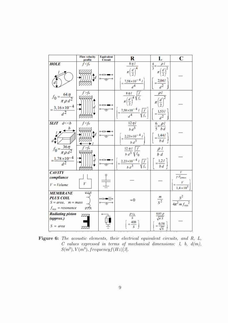
Figure 6: The acoustic elements, their electrical equivalent circuits, and R, L,C values expressed in terms of mechanical dimensions: l, b, d(m),S(m2), V (m3), frequencyf(Hz)[3].
9

5.3 Membranes
Mebrane is usually represented as a series connection of RLC components. Theseacoustic parameters are related to the mechanical ones Rmech, Mms, Cms [1]. Oneof the most reliable ways to obtain these parameters for a moving-coil transducer isto use Thiele-Small procedure. From Fig. 6 we can see that R is normally negligiblein this case except for some special cases, where it is deliberately cultivated usingsandwich membranes with adhesive between [1].
5.4 Radiation impedances
Due to the fact, that most headphones cannot be entirely closed, radiating com-ponents appear due to openings or leaks. These are represented in the first ap-proximation by a parallel combination of R and L connected to ground, which isrigorously true only for a spherical zero-order source [1]. At high frequencies thereal component R predominates and represents the radiation energy loss. Similarlyto holes and slits, this component can be used for resonance damping as well. Atlow frequencies the radiation impedance becomes reactive and is equivalent to amass loading [1]. In most approximations due to low radiation given circuit can bereplaced as a short circuit due to its negligible effect.
6 Isodynamic headphone circuit simulation
For example purposes a simple schematic of an isodynamic headphone was chosen.The purpose of these simulations is to show how the frequency response may shiftwhen some parameters, which resemble a certain characteristic, are changed. Theschematic design and simulations were made using LTspice XVII software. Theelements in Fig. 7 define: Rr and Lr - radiation impedance, Lm and Cm - membrane,C0 - dominant acoustic compliance of the air, R0 and L0 - leak impedance, Rh -porous resistance, C1 - cavity compliance. Note, that the schematic does not includetransduction element, since only the frequency response is simulated and not an SPL(Sound pressure level).
Note, that the given schematic with lumped elements represents a proper frequencyresponse up to 5kHz. Due to the inhomogenity of the sound field, the responseat higher frequencies is not accurate. However, these simulations are useful todemonstrate the main features of certain blocks and how they interconnect. Theresults of the simulations are presented in Fig. 8.
The first curve (green) shows how a frequency response would look like without theradiation resistance and when no porous resistance is present (headphone with noholes or slits). A really high resonance peak displays an electrical equivalence ofa high quality resonator. This peak can only be seen with perfect induction and
10

Figure 7: The schematic of an isodynamic headphone.Example taken from [1]
capacitance elements (no parasitic properties), however, this is highly unrealistic andgives improper results. The second curve (blue) shows how the frequency responsechanges when a normal radiation impedance is present. Due to radiation losses,the quality of the resonant circuit is smaller and the resonant peak is wider andlower. This presents a more realistic case of a headphone frequency response andpresents the importance of a proper and full modelling. The third curve (red)represents the frequency response of the original circuit that is presented in Fig. 7.The lowered resonance peak compared to the second simulation shows how a simplehole in the headphones can be used to modify the frequency response to achievedesired results. And the fourth curve (yellow) represents how an increased membranestiffness affects the lower frequencies if other parameters would remain the same.This shows, that even a small change while manufacturing certain headphones caneasily transform the designed frequency response and add unwanted attenuation oradditional frequency response changes which are usually highly unwanted.
7 Conclusions
In this paper, the history of headphones was presented while showing significantchanges that affected the way headphones are perceived now. The most commontypes of headphones and transducers were presented, which shows that no singlesolution is best in terms of listeners perspective. Additionally, a simple overviewof how headphones are modelled was presented with an example which shows, howcertain parameters affect the full response and how simplifying the simulation circuitcan give a very different and unrealistic result than it was expected. As mentionedin the introduction, this only an overview of how headphone modelling is done andeven here it can be seen, that the complexity of this topic is quite significant andrequires proper analysis and research to fully understand it.
11

Figure 8: Simulation of the schematic with changed parametersGreen - Rr=Rh=0, Blue - Rh=0, Red - original, Yellow - Cm=0.025uF
References
[1] Borwick, J. Loudspeaker and Headphone Handbook. Focal Press, 2001.
[2] Howeth, L. S. History of Communications-Electronics in the United StatesNavy. 1963.
[3] Poldy, C. Headphone fundamentals. In Audio Engineering Society Conference:UK 23rd Conference: Music Everywhere (2006).
[4] Wilson, J. P. High-quality electrostatic headphones. Wireless world (1968).
12