Embed Size (px)
Citation preview

Fujita LaboratoryTokyo Institute of Technology
Tokyo Institute of Technology
Vision-Based Cooperative Control(progress report)
FL08_09_1
Naoto Kobayashi
2Fujita LaboratoryTokyo Institute of Technology
Tokyo Institute of Technology
Outline
IntroductionVision-based Cooperative Control• Problem Formulation• Analysis• Simulation• Experiment
Conclusion / Future Works
3Fujita LaboratoryTokyo Institute of Technology
Tokyo Institute of Technology
Introduction
Cooperative Control• Cooperative control is a distributed control strategy that achieves specified tasks in multi-agent systems. • It’s been motivated by interests in group behavior of animals, formation control of multi-vehicle systems and so on. • It is hoped to be applied to sensor networks, robot networks and many other multi-agents systems.
School of Fishhttp://www.yunphoto.net/
Automated Highway Systemhttp://www.its.go.jp/ITS/ 4
Fujita LaboratoryTokyo Institute of Technology
Tokyo Institute of Technology
Introduction
Cooperative Control• Consensus Problem
: to reach an agreement regarding a certain quantity of interest that depends on the state of all agents.
• Flocking Problem : to make all of agents’ speeds be the same.
• Coverage Problem• Formation Control Problem
:• Pose Synchronization
: to make all of the agents’ positions and attitudes be the same.
Pose synchronization
in particular I address ...leader following problem of pose synchronization
5Fujita LaboratoryTokyo Institute of Technology
Tokyo Institute of Technology
Introduction Vision-based Cooperative Control
Mounted camera configuration
- Each agent can have its own “eyes”. autonomous agents system
Mounted camera (local camera) configuration
Visual Observer [4]- Visual observer that is proposed in [4] can estimate relative positions and attitudes between camera and target objects. Visual feedback system
with visual observer
We have to get necessary information (neighbor’s relative positions and attitudes) from camera images to achieve pose synchronization.
6Fujita LaboratoryTokyo Institute of Technology
Tokyo Institute of Technology
Introduction Last Seminar(FL08_01_1)
This Seminar (FL08_09_1)
• Experiments (bird’s eye camera configuration)• Simulations towards experiments(mounted camera configuration)
• Simulations (mounted camera configuration - leader following -)• Experiments (mounted camera configuration - leader following -)• Convergence analysis (for easier problem)
7Fujita LaboratoryTokyo Institute of Technology
Tokyo Institute of Technology
IntroductionVision-based Cooperative Control• Problem Formulation• Analysis• Simulation• Experiment
Conclusion / Future Works
Outline
8Fujita LaboratoryTokyo Institute of Technology
Tokyo Institute of Technology
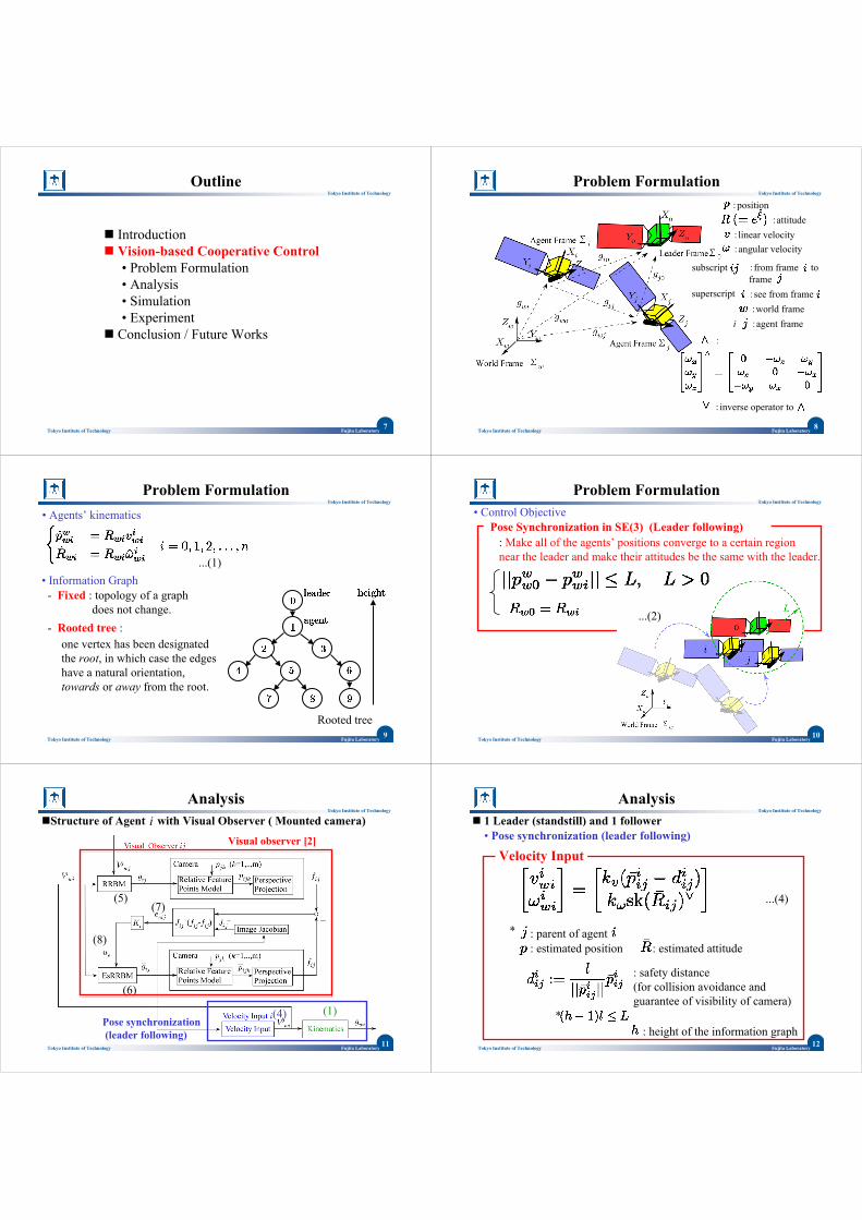
Problem Formulation
:linear velocity
:position:attitude
:angular velocity
i
subscript :from frame to frame
superscript :see from frame
:agent frame:world frame
:
:inverse operator to
9Fujita LaboratoryTokyo Institute of Technology
Tokyo Institute of Technology
Problem Formulation• Agents’ kinematics
...(1)• Information Graph- Fixed : topology of a graph
does not change. - Rooted tree :
Rooted tree
one vertex has been designated the root, in which case the edges have a natural orientation, towards or away from the root.
10Fujita LaboratoryTokyo Institute of Technology
Tokyo Institute of Technology
Problem Formulation• Control Objective
: Make all of the agents’ positions converge to a certain region near the leader and make their attitudes be the same with the leader.
Pose Synchronization in SE(3) (Leader following)
...(2)
11Fujita LaboratoryTokyo Institute of Technology
Tokyo Institute of Technology
Pose synchronization(leader following)
AnalysisiStructure of Agent with Visual Observer ( Mounted camera)
(1)(4)
(5)
(6)
(7)
(8)
Visual observer [2]
12Fujita LaboratoryTokyo Institute of Technology
Tokyo Institute of Technology
1 Leader (standstill) and 1 follower
...(4)
: estimated position : estimated attitude
: safety distance(for collision avoidance and guarantee of visibility of camera)
*
Velocity Input
*
Analysis
: height of the information graph
: parent of agent
• Pose synchronization (leader following)
13Fujita LaboratoryTokyo Institute of Technology
Tokyo Institute of Technology
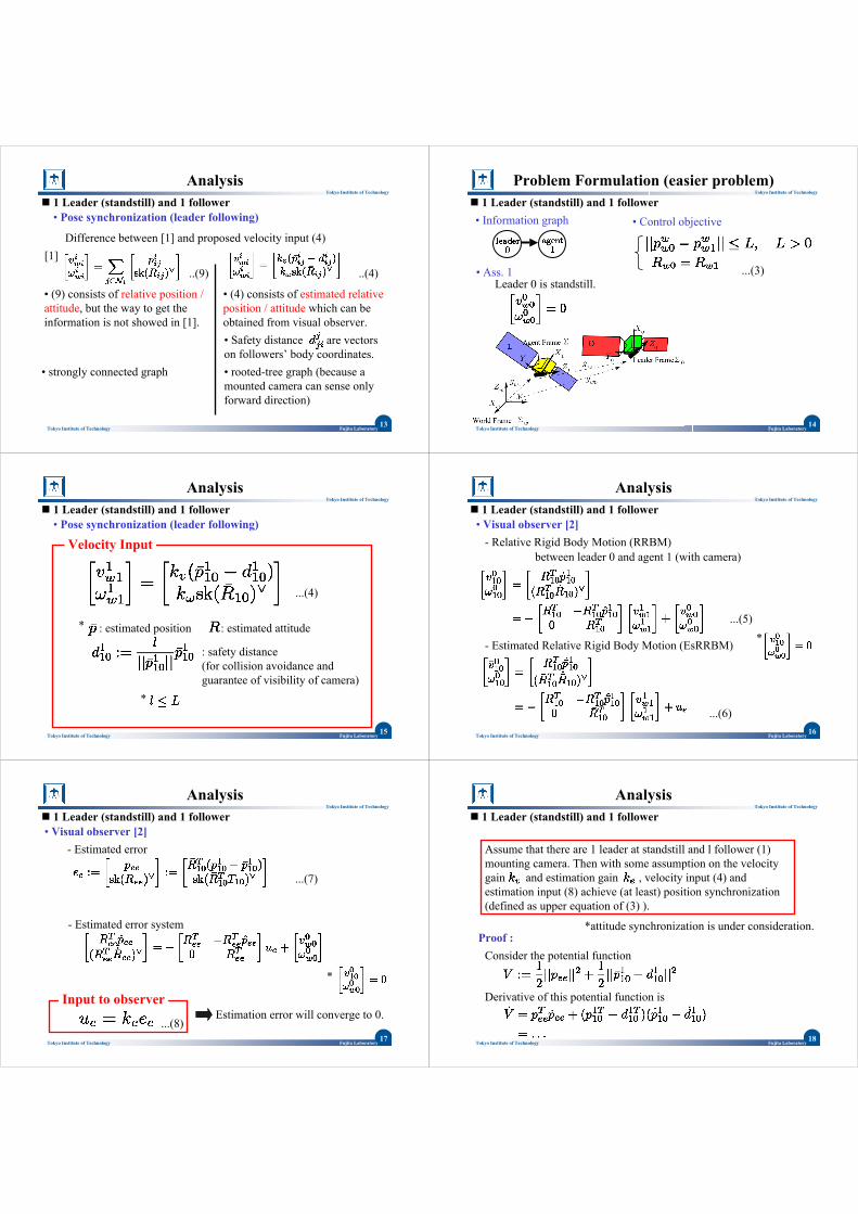
1 Leader (standstill) and 1 follower• Pose synchronization (leader following)
Difference between [1] and proposed velocity input (4)
Analysis
• (4) consists of estimated relative position / attitude which can be obtained from visual observer.
..(9)[1]
..(4)
• (9) consists of relative position / attitude, but the way to get the information is not showed in [1].
• Safety distance are vectors on followers’ body coordinates. • rooted-tree graph (because a mounted camera can sense only forward direction)
• strongly connected graph
14Fujita LaboratoryTokyo Institute of Technology
Tokyo Institute of Technology
Problem Formulation (easier problem)1 Leader (standstill) and 1 follower
• Ass. 1Leader 0 is standstill.
• Information graph • Control objective
...(3)
15Fujita LaboratoryTokyo Institute of Technology
Tokyo Institute of Technology
1 Leader (standstill) and 1 follower
...(4)
: estimated position : estimated attitude
: safety distance(for collision avoidance and guarantee of visibility of camera)
*
Velocity Input
*
Analysis
• Pose synchronization (leader following)
16Fujita LaboratoryTokyo Institute of Technology
Tokyo Institute of Technology
1 Leader (standstill) and 1 follower• Visual observer [2]
- Relative Rigid Body Motion (RRBM)
...(5)
- Estimated Relative Rigid Body Motion (EsRRBM)
between leader 0 and agent 1 (with camera)
...(6)
*
Analysis
17Fujita LaboratoryTokyo Institute of Technology
Tokyo Institute of Technology
1 Leader (standstill) and 1 follower• Visual observer [2]
- Estimated error
...(7)
- Estimated error system
*
Input to observerEstimation error will converge to 0.
Analysis
...(8)18
Fujita LaboratoryTokyo Institute of Technology
Tokyo Institute of Technology
1 Leader (standstill) and 1 follower
Analysis
Assume that there are 1 leader at standstill and l follower (1) mounting camera. Then with some assumption on the velocity gain and estimation gain , velocity input (4) and estimation input (8) achieve (at least) position synchronization(defined as upper equation of (3) ).
*attitude synchronization is under consideration. Proof :
Consider the potential function
Derivative of this potential function is
19Fujita LaboratoryTokyo Institute of Technology
Tokyo Institute of Technology
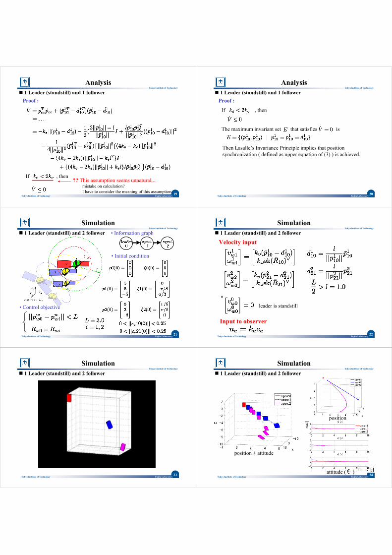
1 Leader (standstill) and 1 follower
Analysis
Proof :
If , then ?? This assumption seems unnatural...
mistake on calculation? I have to consider the meaning of this assumption. 20
Fujita LaboratoryTokyo Institute of Technology
Tokyo Institute of Technology
1 Leader (standstill) and 1 follower
Analysis
Proof :
If , then
The maximum invariant set that satisfies is
Then Lasalle’s Invariance Principle implies that position synchronization ( defined as upper equation of (3) ) is achieved.
21Fujita LaboratoryTokyo Institute of Technology
Tokyo Institute of Technology
Simulation1 Leader (standstill) and 2 follower
• Control objective
• Information graph
• Initial condition
22Fujita LaboratoryTokyo Institute of Technology
Tokyo Institute of Technology
Simulation1 Leader (standstill) and 2 follower
Velocity input
Input to observer
*leader is standstill
23Fujita LaboratoryTokyo Institute of Technology
Tokyo Institute of Technology
Simulation1 Leader (standstill) and 2 follower
24Fujita LaboratoryTokyo Institute of Technology
Tokyo Institute of Technology
Simulation1 Leader (standstill) and 2 follower
position + attitude
position
attitude ( )
25Fujita LaboratoryTokyo Institute of Technology
Tokyo Institute of Technology
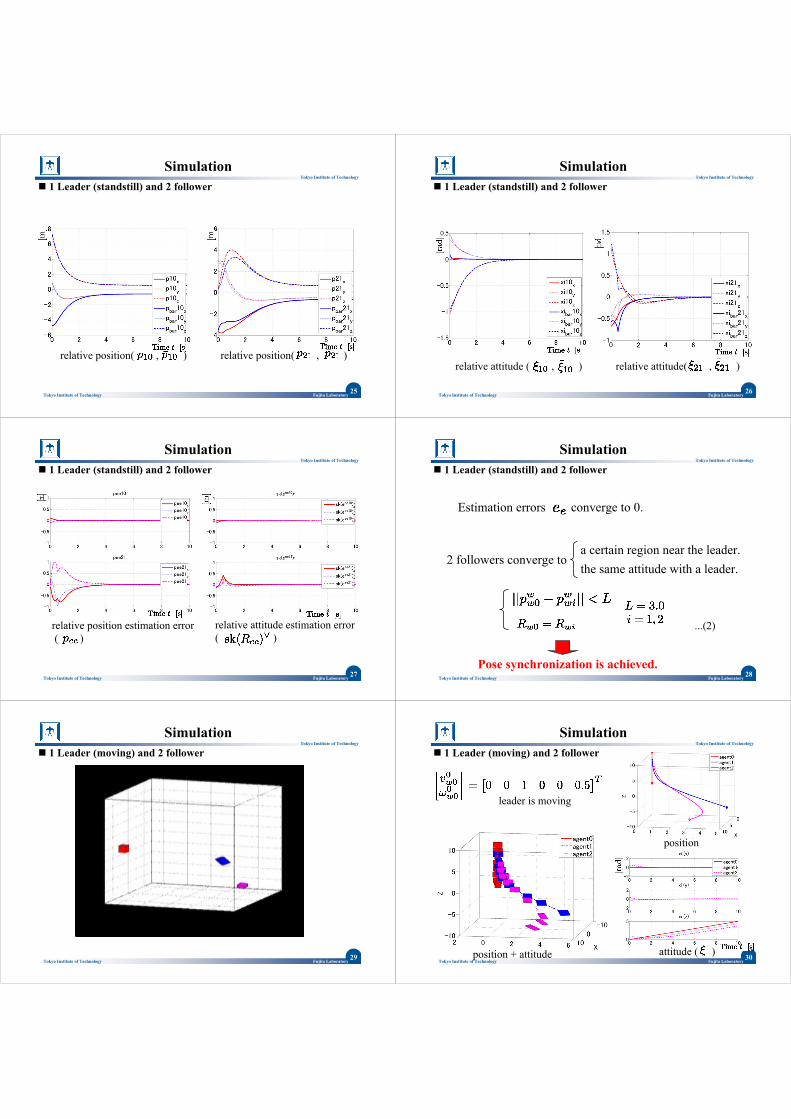
Simulation1 Leader (standstill) and 2 follower
relative position( , ) relative position( , )
26Fujita LaboratoryTokyo Institute of Technology
Tokyo Institute of Technology
Simulation1 Leader (standstill) and 2 follower
relative attitude ( , ) relative attitude( , )
27Fujita LaboratoryTokyo Institute of Technology
Tokyo Institute of Technology
Simulation1 Leader (standstill) and 2 follower
relative position estimation error( )
relative attitude estimation error ( )
28Fujita LaboratoryTokyo Institute of Technology
Tokyo Institute of Technology
Simulation1 Leader (standstill) and 2 follower
Estimation errors converge to 0.
2 followers converge to the same attitude with a leader. a certain region near the leader.
Pose synchronization is achieved.
...(2)
29Fujita LaboratoryTokyo Institute of Technology
Tokyo Institute of Technology
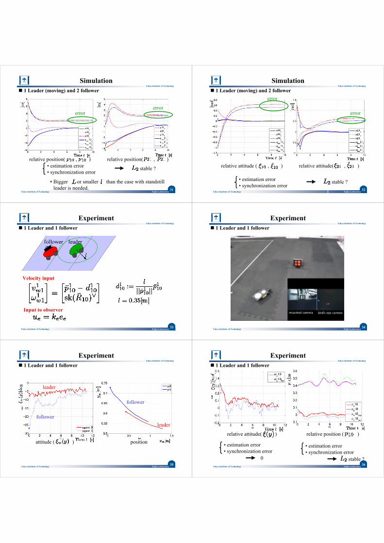
Simulation1 Leader (moving) and 2 follower
30Fujita LaboratoryTokyo Institute of Technology
Tokyo Institute of Technology
Simulation1 Leader (moving) and 2 follower
position + attitude
position
attitude ( )
leader is moving
31Fujita LaboratoryTokyo Institute of Technology
Tokyo Institute of Technology
Simulation1 Leader (moving) and 2 follower
relative position( , ) relative position( , )
errorerror
• estimation error• synchronization error
stable ?
Bigger or smaller than the case with standstill leader is needed.
*32
Fujita LaboratoryTokyo Institute of Technology
Tokyo Institute of Technology
Simulation1 Leader (moving) and 2 follower
relative attitude ( , ) relative attitude( , )
error
error
• estimation error• synchronization error
stable ?
33Fujita LaboratoryTokyo Institute of Technology
Tokyo Institute of Technology
Experiment1 Leader and 1 follower
Velocity input
Input to observer
34Fujita LaboratoryTokyo Institute of Technology
Tokyo Institute of Technology
1 Leader and 1 follower
Experiment
35Fujita LaboratoryTokyo Institute of Technology
Tokyo Institute of Technology
1 Leader and 1 follower
attitude ( ) position
leader
follower
leader
follower
Experiment
36Fujita LaboratoryTokyo Institute of Technology
Tokyo Institute of Technology
1 Leader and 1 follower
relative position ( )relative attitude( )
Experiment
• estimation error• synchronization error
stable ?
• estimation error• synchronization error
0
37Fujita LaboratoryTokyo Institute of Technology
Tokyo Institute of Technology
1 Leader and 1 follower
Pose synchronization is achieved.
Experiment
A follower converge to the same attitude with a leader. a certain region near the leader.
...(2)
Generally, bigger or smaller than the case with standstill leader is needed.
*
38Fujita LaboratoryTokyo Institute of Technology
Tokyo Institute of Technology
IntroductionVision-based Cooperative Control• Problem Formulation• Analysis• Simulation• Experiment
Conclusion / Future Works
Outline
39Fujita LaboratoryTokyo Institute of Technology
Tokyo Institute of Technology
Conclusion / Future Works
Conclusion• Problem formulation ( vision-based leader following of pose synchronization) •Convergence analysis (for easier problem) • Simulations• Experiments (1 leader and 1 follower)
Future Works
• Convergence analysis (moving leader, multi-follower)• Experiments ( 1 leader and 2 follower )
40Fujita LaboratoryTokyo Institute of Technology
Tokyo Institute of Technology
References
[1]Y. Igarashi, T. Hatanaka and M. Fujita, Output Synchronization in SE(3) -Passivity-based Approach- ,Proc. of the 36th SICE Symposium on Control Theory, 35/38, 2007.
[2]R. O. Saber, J. A. Fax and T. M. Murray, Consensus and Cooperation in Networked Multi-Agent Systems, Proc. of the IEEE, 95-1, 215/233, 2007.
[3]N. Moshtagh and A. Jadbabaie, Distributed Geodesic Control Laws for Flocking ofNonholonomic Agents, IEEE Trans. on Automatic Control, 52-4, 681/686, 2007.
[4] M. Fujita, H. Kawai and M. W. Spong, Passivity-based Dynamic Visual Feedback Control for Three Dimensional Target Tracking:Stability and L2-gain Performance Analysis, IEEE Trans. on Control Systems Technology, vol. 15, no. 1, 40/52, 2007.