Embed Size (px)
Citation preview

Outline of the Mirai
Key Specifications
The Mirai is a fuel cell vehicle (FCV) which uses hydrogen as energy to generate electricity and power the vehicle. Fuel cell systemThe hydrogen that powers the Mirai, hydrogen, can be produced from various types of primary sources, making it a promising alternative to current energy sources. The Toyota Fuel Cell System (TFCS) combines proprietary fuel cell technology that includes the Toyota FC Stack and high-pressure hydrogen tanks with the hybrid technology. The TFCS has high energy efficiency compared with conventional internal combustion engines, along with superior environmental performance highlighted by zero emissions of CO2 and other pollutants during vehicle operation. The hydrogen tanks can be refuelled in approximately three minutes *1, and with an ample cruising range, the system promises convenience on par with gasoline engine vehicles.
The Mirai’s valueThe Mirai offers the kind of exceptional value drivers would expect from a next-generation car: distinctive exterior design, excellent acceleration performance and unmatched quietness thanks to motor propulsion at all speeds, in addition to enhanced driving pleasure due to a low center of gravity bringing greater handling stability.
*1 Toyota measurement under SAEJ2601 standards (ambient temperature: 20 °C; hydrogen tank pressure when fueled: 10 MPa). Fueling time varies with hydrogen fueling pressure and ambient temperature.
VehicleCruising range
Approx. 550 km Estimated, according to NEDC Cycle
Maximum speed 178 km/h
Fuel cell stack
Volume power density 3.1 kW/L (world top level *2)
Maximum output 114 kW (155 DIN hp)
High-pressure hydrogen tank
Number of tanks 2
Nominal working pressure 70 MPa (700 bar)
Tank storage density *3 5.7 wt% (world top level *2)
MotorMaximum output 113 kW (154 DIN hp)
Maximum torque 335 Nm
*2 November 2014, Toyota data
*3 Hydrogen storage mass per tank weight
Driving performance Dimensions / seating capacityLength 4,890 mm
Width 1,815 mm
Height 1,535 mm
Curb weight 1,850 kg
Wheelbase 2,780 mm
Track (front / rear) 1,535 mm / 1,545 mm
Minimum ground clearance 130 mm
Interior dimensions
Length 2,040 mm
Width 1,465 mm
Height 1,185 mm
Seating capacity 4
Width 1,815 mm
Length 4,890 mm
Wheelbase 2,780 mm
Height 1,535 mm
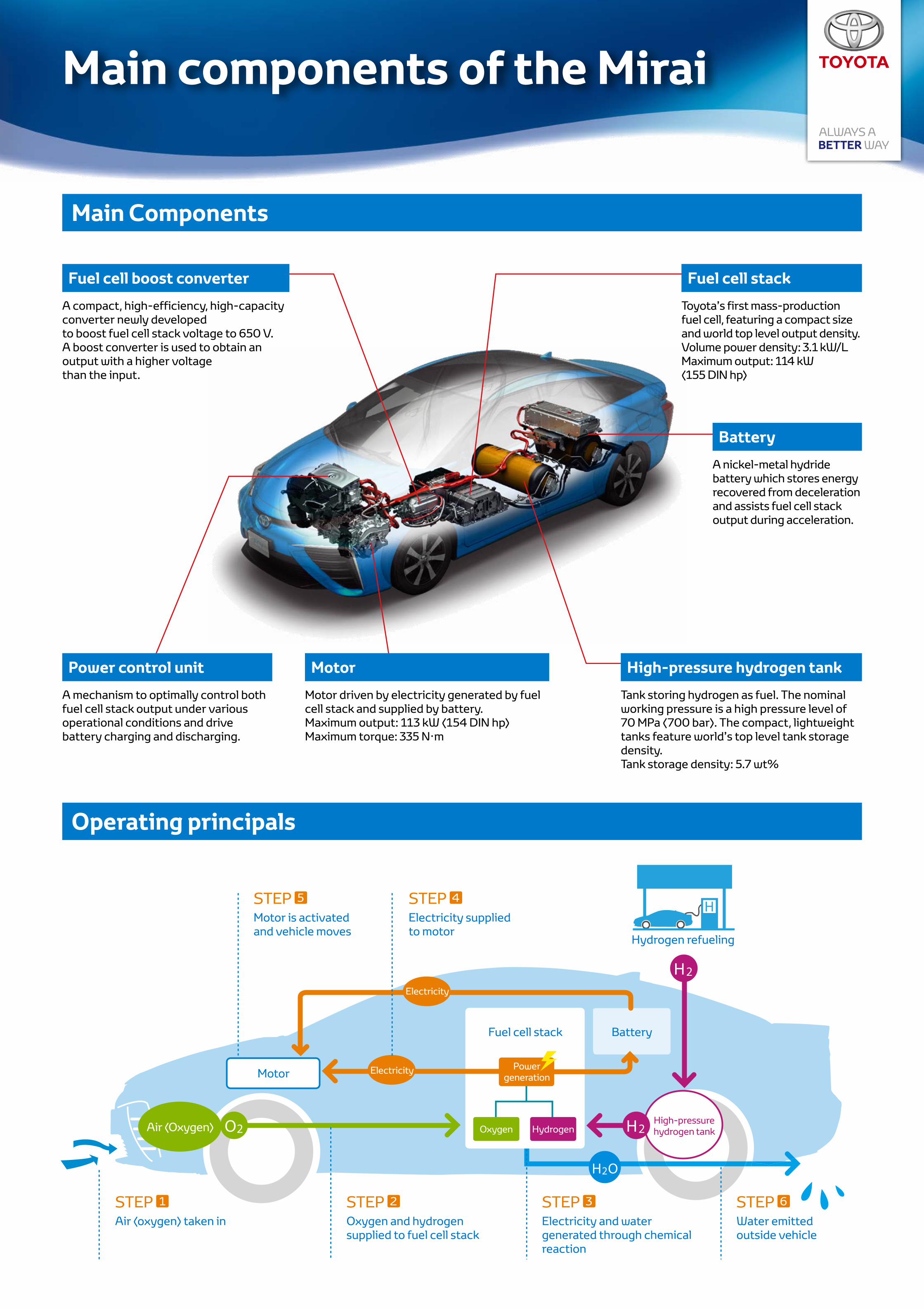
Main components of the Mirai
Main Components
Operating principals
Fuel cell boost converter Fuel cell stack
Battery
Motor High-pressure hydrogen tankPower control unit
A mechanism to optimally control both fuel cell stack output under various operational conditions and drive battery charging and discharging.
Motor is activated and vehicle moves
Air (oxygen) taken in Oxygen and hydrogen supplied to fuel cell stack
Water emitted outside vehicle
Electricity and water generated through chemical reaction
Electricity supplied to motor
Hydrogen refueling
STEP 5
STEP 1 STEP 2 STEP 6STEP 3
STEP 4
A compact, high-efficiency, high-capacity converter newly developedto boost fuel cell stack voltage to 650 V. A boost converter is used to obtain an output with a higher voltagethan the input.
Toyota’s first mass-production fuel cell, featuring a compact size and world top level output density.Volume power density: 3.1 kW/LMaximum output: 114 kW (155 DIN hp)
A nickel-metal hydride battery which stores energy recovered from deceleration and assists fuel cell stack output during acceleration.
Motor driven by electricity generated by fuel cell stack and supplied by battery.Maximum output: 113 kW (154 DIN hp)Maximum torque: 335 N·m
Tank storing hydrogen as fuel. The nominal working pressure is a high pressure level of 70 MPa (700 bar). The compact, lightweight tanks feature world’s top level tank storage density.Tank storage density: 5.7 wt%
Motor
Fuel cell stack Battery
Electricity
Electricity
Air (Oxygen)
Power generation
Oxygen HydrogenHigh-pressure hydrogen tank

Driving performance of the Mirai
Superior drive-start acceleration performance
An unprecedented drive feel born from motor-based driving
Toyota Fuel Cell System (TFCS) achieves driving pleasure
The Mirai offers far more than superior environmental performance. From the start of driving, the Mirai features a smooth and gliding feel, which promises exceptional driving pleasure, combining a high level of cornering performance through winding roads with superior acceleration and quiet operation.
Superior acceleration offers drive-start acceleration (from 0 to 100 km/h) of 9.6 seconds and passing acceleration of 3.0 seconds (from 40 to 70 km/h)
Acceleration performance comparison (Toyota measurements) Conversation articulation comparison (Toyota measurements)
The highly sound-insulating body and motor propulsion at all speeds deliver outstanding quietness
Outstanding quiet drive
Drive-start acceleration 0–100 km/h (seconds)
Pass
ing
acce
lera
tion
40
–70
km
/h (s
econ
ds)
Battery
Low center of gravity Aerodynamics
High-level cornering performance
Contributes to superior handling stability and quietness
Since the vehicle does not emit heated gases, the floor can be fully covered. Air resistance is reduced to boost fuel efficiency.
The design of the clearance lamps contributes to the aerodynamics. Aero-stabilizing fins are positioned next to the rear combination
lamps. This improves straight-driving stability.
Fuel cell stack, high-pressure hydrogen tanks and other power unit components are placed under vehicle floor.
The lower center of gravity raises handling stability and produces a comfortable driving experience by reducing changes in vehicle position.
The front-rear weight balance is adjusted to produce a midship feel despite the front wheel drive design.
Fuel cell stack High-pressure hydrogen tankFull underbody covering Clearance lamps
designed to streamline airflow
Aero-stabilizing fins
5
4
3
10 12 14
n HV1n HV2
MIRAI
n FCV (Toyota FCHV-adv)
Goodn EV
MIRAI
n HV1
n EVn FCV
(Toyota FCHV-adv)
n HV2
Good
2006 2008 2010 2012 2014
120
km
/h A
I (%
)
80
70

Power performance of cold start capability
Issues concerning FCVs cold start capability
Improving cold start capability
Example of evaluation in an extremely cold region
Maintaining good power generation from a fuel cell requires water. In environments below the freezing point, however, excess water freezes, impeding the supply of air (oxygen) and hydrogen and causing a decrease in power generation performance.
We made it possible to start the vehicle at –30 °C and to achieve output at levels satisfactory for practical use immediately after starting. Improved power generating performance immediately after starting below the freezing point • Higher cell flow channel and electrode performance (exclusion of generated water and air (oxygen) diffusion
were improved to achieve excellent power generating performance even below the freezing point) • Establishment of intra-cell water volume control technology (the volume of water is measured and controlled
at a volume suitable for power generating performance below the freezing point) Improved warming-up performance • Lower thermal capacity as a result of higher fuel cell stack output density • Establishment of fuel cell rapid warm-up control technology (heat generated by the fuel cell is controlled to
drastically reduce warm-up time)
Yellowknife, Canada evaluation (2014)Evaluation of fuel cell stack output performance immediately after starting after parking the vehicle outdoors overnight (17 hours)
Evaluations were performed in extremely cold regions including Yellowknife, Canada; Rovaniemi, Finland; and Shibetsu, Japan, confirming suitability for these environments.
Vehicle parking conditions 100% output 70 seconds after starting
–20 °C
–30 °C
Vehicle stopped
Am
bien
t tem
pera
ture
(°C
)
Parked for 17 hours
0:00 12:00 0:00 12:00
00
20
40
60
80
100
20 40 60 80 100
Start
Start 60% output 35 seconds after starting
Fuel cell stack output (%)
Elapsed time after starting (seconds)
100%
100%
60%
0
–10
–20
–30
–40
Elapsed time after starting (seconds)0
0
20
40
60
80
100
20 40 60 80 100
Accelerator position (% open)

Fuel cell stack assembly
The fuel cell stack assembly comprises the fuel cell stack, auxiliary components (hydrogen circulating pump, etc.) and fuel cell boost converter. Integrating these components achieves a smaller, lighter, and less expensive fuel cell stack assembly.
Fuel cell stack assembly structure and main specifications
Toyota FC stack
Auxiliary components
Fuel cell boost converterMaximum output voltage: 650 VNumber of phases: 4 phases
*1 November 2014; Toyota dataHydrogen circulating pump, etc.
Type: Polymer electrolyte fuel cellMaximum output: 114 kW (155 DIN hp)Volume power density: 3.1 kW/L (world top level *1)Humidification system: Internal circulation system (humidifier-less; world-first *1)

Toyota FC Stack
Breakthroughs in fuel cell technology have led to the creation of a smaller, lighter new fuel cell stack with enhanced performance.The new stack has a volume power density of 3.1 kW/L – among the world top level *3 –, and can now be mounted underneath the floor of a sedan.
New fuel cell stack with increased output density (enhanced performance, more compact sized)
Volume power density 3.1 kW/L
New fuel cell stack (Mirai)Titanium3D fine-mesh flow field (cathode, world-first*3)
2008 model *1
Stainless steel, straight channel
2002 model *2
Molded carbon, straight channel
2008 model *1 fuel cell stack
1.4 kW/L(Maximum output: 90 kW / volume: 64 L; weight: 108 kg)
Constant pressure fastening
200 cells × dual-line stacking = 400 cells
Spring
*1 2008 model: Toyota FCHV-adv *2 2002 model: Toyota FCHV *3 November 2014, Toyota data
3.1 kW/L(Maximum output: 114 kW / volume: 37 L; weight: 56 kg)
New fuel cell stack (Mirai)
2.2 times better volume power density
Mass power density (kW/kg)
Vol
ume
pow
er d
ensi
ty (k
W/L
)
World top level *3
0
0.5
0.5 1.0 1.5 2.0 2.5
1.0
1.5
2.0
2.5
3.0
3.5
Constant dimension fastening
Single-line stacking
370 cells
2008 model *1 fuel cell stack New fuel cell stack (Mirai)
Maximum output 90 kW 114 kW (155 DIN hp)
Volume power density / Mass power density 1.4 kW/L / 0.83 kW/kg 3.1 kW/L (World top level *3) / 2.0 kW/kg
Volume / Weight 64 L / 108 kg 37 L / 56 kg (Cell + fastener)
Cell Number of cells in one stack 400 cells (dual-line stacking) 370 cells (single-line stacking)
Thickness 1.68 mm 1.34 mm
Weight 166 g 102 g
Flow channel Straight channel 3D fine-mesh flow field (cathode, world-first *3)
Mounting position Motor room (SUV) Under floor (Sedan)

Cell
Higher performance of new cells
To increase the power generating performance of the cells, it is important to enhance the water exclusion of produced water and promote the diffusion of air (oxygen).The new cells achieve a high current density by enhancing both the uniformity of generation in cell surfaces and electrode responsiveness with innovative flow channel structures and electrodes.
Generated water is quickly drawn out through hydrophilic 3D fine-mesh flow field (world-first*2), preventing obstruction of the flow of air (oxygen) by accumulated water.
Turbulent flows, resulting from the narrowness of the flow channel rib width, promote the diffusion of oxygen to the catalyst layer.
Flow channel rib width is large meaning the generated water tends to be retained, impeding the diffusion of air (oxygen) to the catalyst layer and reducing power generation performance.
Gas diffusion layer: Lower density and thinner base material
Gas diffusion performance more than doubled
Electrolyte membrane: Thinner by one-third
Proton conductivity increased by 3 times
Catalyst layer: Highly reactive Pt/Co alloy catalyst
Activity increased by 1.8 times
Current density (A/cm2)
Cel
l vol
tage
(V)
*1 2008 model: Toyota FCHV-adv *2 November 2014, Toyota data
World top level*2
2008 model cell *1
Narrow flow channel rib width
Wid
e flo
w c
hann
el ri
b w
idth
Air
(Oxy
gen)
Air (Oxygen)
HydrogenWorld-first *2
Water exclusion
Diffusibility
Hydrogen
Water produced from electric power generation tended to block the flow channels, impeding the flow of air (oxygen)
Innovations to cell flow channels (Cathode)Flow channels: Using 3D fine-mesh flow field (world-first *2) simultaneously improves water exclusion and air (oxygen) diffusion, achieving uniform generation in cell surfaces.3D fine-mesh flow field: A flow channel with a three-dimensional fine mesh structure
Electrode innovationsThe electrolyte membrane was made thinner, the diffusion performance of the gas diffusion layer was increased, and the catalyst was hyper-activated to greatly enhance electrode responsiveness.
New cell (Mirai) 2008 model cell *1
Current density 2.4 times higher
New cell

Internal circulation system – Humidifier-less
The new fuel cell stack performs self-humidification by circulating water produced from power generation within the cells, eliminating the need for external humidification. This makes it possible to eliminate the humidifier (world-first *1), making the system smaller and lighter.
Internal circulation system – Humidifier-lessThe system self-humidifies by circulating water (water vapor) produced from power generation within the cells in order to maintain the proton conductivity performance of the electrolyte membrane.
High-pressure hydrogen tank
High-pressure hydrogen tank
Pressure controller
Pressure controller
Hydrogen circulating pump
Hydrogen circulating pump
Hydrogen inlet
Hydrogen inlet
Promotes back-diffusion of generated water
Electrolyte membrane
Electrolyte membrane
Less back-diffusion of generated water
Low volume of circulated hydrogen, and low supply
volume of water vapor from the anode upstream to
downstream Only water vapor is retrieved from the emitted air, and this is used to humidify
the supplied air.
Air outlet
Air outlet
Air inlet (dry)
Air inlet (wet)
Air compressor
Air compressor
Humidifier
*1 November 2014, Toyota data
Earlier systems used a humidifier
Exte
rnal
circ
ulat
ion
Proton
Proton
Increases coolant water volume in upstream air and suppresses temperature increase and also
suppresses evapotranspiration of generated water.
Air and hydrogen flow in opposite directions, humidifying upstream
air flow, which tends to dry out
Increased water vapor supply from the anode upstream to
downstream
Hydrogen outlet
Hydrogen outlet
Thinner electrolyte membrane World-first *1
Increased hydrogen circulation volume
Humidification from anode
Suppression of evapotranspiration
Inte
rnal
ci
rcul
atio
n System simplified by eliminating humidifier
Size reduction: –15 LWeight reduction: –13 kg
External circulating humidifier (previous system)The system humidifies the supplied air (oxygen) using a humidifier to maintain the proton conductivity of the electrolyte membrane.

Fuel cell boost converter
By developing a high-capacity fuel cell boost converter, it was possible to increase the voltage of the motor, reduce the number of fuel cell stack cells, and reduce the size and weight of the system.Also, innovations to the voltage-boost control and case structure provide exceptionally quiet operation.In addition, the new system can be used with existing hybrid units, enhancing reliability and greatly reducing costs.
Fuel cell boost converter
Fuel cell
MIRAI 2008 model *1
Fuel cell
Motor Motor
*1 2008 model: Toyota FCHV-adv
650 V 250 V
Specially developed for the FCV
Use of existing hybrid units
Main specifications of fuel cell boost converter
Maximum output voltage 650 V
Volume 13 L
Number of phases 4
Cooling method Water-cooled
Fuel cell stack
Newly developed
Fuel cell stack
Newly developed
Fuel cell boost
converter
Battery
Existing units used
Power control unit
Existing units used
Power control unit
Newly developed
Motor
Newly developed
Battery
Existing units used
Motor
Existing units used

High-pressure hydrogen tank
Nominal working pressure 70 MPa (700 bar)
Tank storage density 5.7 wt% (world top level *2)
Tank internal volume
122.4 L (front tank: 60.0 L, rear tank: 62.4 L)
Hydrogen storage mass Approx. 5.0 kg
In-house development of high-pressure hydrogen tank since 2000
*1 Hydrogen storage mass per tank weight
Lighter weight achieved through innovations of carbon fiber reinforced plastic layer structure
Tank storage density of 5.7 wt% achieved, a world top level *2 Innovations to the plastic liner configuration and efficient layering pattern resulted in a reduction of approximately 40% in the amount of carbon fiber used
Cylindrical section
Cylindrical section
Plastic liner (seals in hydrogen)
Plastic liner
Conventional technology New technology
*2 November 2014, Toyota data
Carbon fiber-reinforced plastic layer (ensures pressure resistance)
Glass fiber-reinforced plastic layer (protects surface)
High-pressure hydrogen tank
Boundary section
Boundary section
Dome section
Dome section
Low angle helical winding
High angle helical winding
Hoop windingBoss
Tank storage density *1
Hydrogen refueling
World top level *2
In response to new fueling standards *3 (the same in Japan, the US, and Europe), fueling time of approximately 3 minutes *4 has been achieved*3 (Refueling devices) ISO 17268: Gaseous Hydrogen Land Vehicle Refueling Connection Devices
(Refueling methods) SAE J2601: Fueling Protocols for Light Duty Gaseous Hydrogen Surface Vehicles (Communications fueling) SAE J2799: 70 MPa Compressed Hydrogen Surface Vehicle Fueling Connection Device and Optional Vehicle to Station Communications
*4 Toyota measurement under SAEJ2601 standards (ambient temperature: 20 °C; hydrogen tank pressure when fueled: 10 MPa). Fueling time varies with hydrogen fueling pressure and ambient temperature.
Pressure
sensorTank
informationInfrared ray transmitter
High-pressure hydrogen tank
Temperature sensor
Nozzle
Hydrogen station 2008 model (Toyota FCHV-adv)
Refueling time
Refueling time of
approx. 3 minutes *4
New model (MIRAI)
Vehicle
Hydrogen
Communications functions given to
nozzle and fuel filler