Embed Size (px)
Citation preview
1
Outage Performance of a Multiuser Distributed
Antenna System in Underwater Acoustic Channels
Zhaohui Wang†, Shengli Zhou†, Zhengdao Wang‡, Josko Catipovic§ and Peter Willett†
† Dept. of Electrical and Computer Engineering, University of Connecticut, Storrs, CT 06269, USA‡ Dept. of Electrical and Computer Engineering, Iowa State University, Ames, IA 50011, USA
§ Naval Undersea Warfare Center, Newport, RI 02841, USA
Abstract—The distributed antenna system (DAS) has beenknown for providing a large coverage and throughput in terres-trial radio environments. In this work, we investigate the benefitsof DAS relative to the centralized antenna system (CAS) in un-derwater acoustic (UWA) environments. In particular, we analyzethe outage performance in the wideband uplink transmissions.Based on theoretical derivation and numerical results, we showthat at a medium transmission SNR regime, DAS outperformsCAS in both single-user and multiuser systems. To address the co-channel interference in the multiuser DAS, we suggest a multicellstructure, which is shown having a lower outage error floorrelative to the structure which takes the operation area as asingle cell.
Index Terms—Distributed antenna system, underwater acous-tic channels, outage performance
I. INTRODUCTION
The last decade has witnessed significant progress in under-
water acoustic (UWA) communications, with typical advance-
ments for both single-carrier and multicarrier techniques in
e.g. [1]–[5]. As the point-to-point communication gradually
becomes mature, interests start growing on the underwater
acoustic networking.
Out of a myriad of network architectures, the distributed
antenna system (DAS), which was originally proposed for the
indoor wireless communications in 1980s [6], draws consider-
able attention in the wireless research community. Relative to
the centralized antenna system (CAS), DAS which is formed
by multiple distributed antenna element (DAE), provides a
larger coverage and a higher throughput for the network with
nomadic users [6]–[9].
In terms of the sytem outage performance, primary works
on DAS in terrestrial radio environments can be found in
[10]–[12]. Assuming a Rayleigh-lognormal flat fading channel,
the outage performance of a single-cell single-use DAS is
numerically studied in [10], which shows that the optimal
performance can be achieved with fully distributed antennas.
Using random matrix theory, a closed-form expression of the
uplink outage probability in the distributed multi-input multi-
output (MIMO) maximum-ratio-combining (MRC) system is
derived in [11], with an assumption that the number of transmit
antennas is no less than that of receive antennas. In [12],
the downlink outage probability is derived for DAS in both
This work by Z.-H. Wang and S. Zhou was supported by the ONR grantN00014-09-1-0704 (PECASE) and the NSF grant ECCS-1128581.
A network anchored at sea bottom A data collection network
surfaceAUV
bottom
gateway
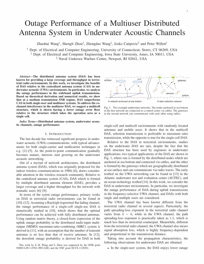
sensors
Fig. 1. Two example underwater networks. The nodes anchored at sea bottomin the first network are connected to a control center via cables. The gatewaysin the second network can communicate with each other using radios.
single-cell and multicell environments with randomly located
antennas and mobile users. It shows that in the multicell
DAS, selection transmission is preferable to maximum ratio
transmission, while the opposite is true for the single-cell DAS.
Relative to the DAS in terrestrial environments, studies
on the underwater DAS are rare, despite the fact that the
DAS structure has been used by engineers in underwater
applications; two typical applications of the DAS are shown in
Fig. 1, where one is formed by the distributed nodes which are
anchored at sea bottom and connected via cables, and the other
is formed by the gateways which are geographically distributed
at sea surface and can communicate via radio waves. The early
testbed on the UWA networking can be found in [13] in the
Atlantic underwater test and evaluation center (AUTEC), and
an ocean technology testbed [14]. In this work, we consider the
DAS in underwater environments. In particular, we investigate
the outage performance of DAS during uplink transmissions
in the frequency-selective UWA channel, and DASs with both
single and multiple users are considered.
The UWA channel has been known different from the
terrestrial radio channel in several aspects. Particularly, the
path spreading-loss exponent in the terrestrial radio channel
varies from 3 ∼ 6, while in the UWA channel, the path
spreading-loss exponent is practically taken as 1.5, which is
much less than its terrestrial counterpart. Meanwhile, different
from the terrestrial radio channel, the UWA channel also incurs
signal absorption loss, which is highly frequency-dependent
and proportional to the transmission distance.
Taking into account the propagation characteristics, the
following observations for underwater DAS are obtained.
• In the single-user system, the DAS enjoys lower outage
2
probabilities than CAS in the moderate transmission SNR
region, and the superiority of DAS over CAS increases
as the signal frequency increases;
• In the multiuser DAS, a multicell based uplink transmis-
sion yields better outage performance than the single-cell
based uplink transmission.
The rest of the paper is organized as follows. A system
model for the multiuser underwater DAS is developed in
Section II. The outage probabilities of the single-user DAS and
multiuser DAS are derived in Sections III and IV, respectively.
Conclusions are drawn in Section V.
II. SYSTEM MODEL FOR MULTIUSER UNDERWATER DAS
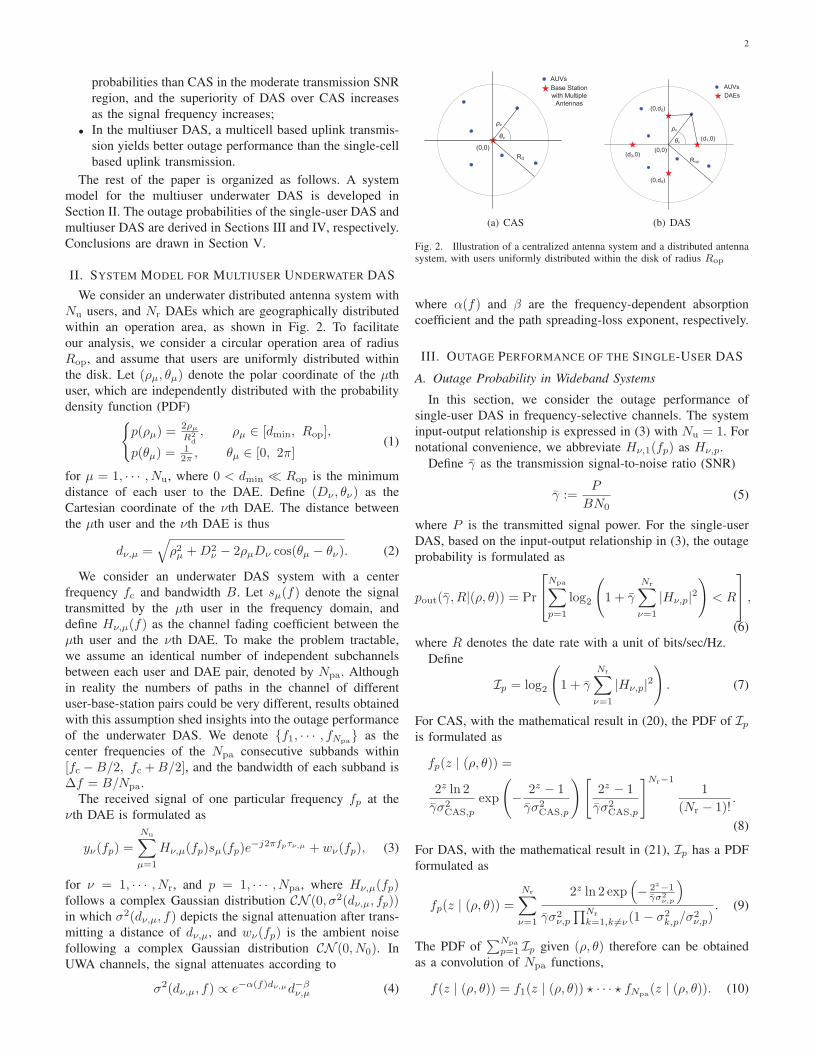
We consider an underwater distributed antenna system with
Nu users, and Nr DAEs which are geographically distributed
within an operation area, as shown in Fig. 2. To facilitate
our analysis, we consider a circular operation area of radius
Rop, and assume that users are uniformly distributed within
the disk. Let (ρµ, θµ) denote the polar coordinate of the µth
user, which are independently distributed with the probability
density function (PDF){
p(ρµ) =2ρµ
R2d
, ρµ ∈ [dmin, Rop],
p(θµ) =12π , θµ ∈ [0, 2π]
(1)
for µ = 1, · · · , Nu, where 0 < dmin ≪ Rop is the minimum
distance of each user to the DAE. Define (Dν , θν) as the
Cartesian coordinate of the νth DAE. The distance between
the µth user and the νth DAE is thus
dν,µ =√
ρ2µ +D2ν − 2ρµDν cos(θµ − θν). (2)
We consider an underwater DAS system with a center
frequency fc and bandwidth B. Let sµ(f) denote the signal
transmitted by the µth user in the frequency domain, and
define Hν,µ(f) as the channel fading coefficient between the
µth user and the νth DAE. To make the problem tractable,
we assume an identical number of independent subchannels
between each user and DAE pair, denoted by Npa. Although
in reality the numbers of paths in the channel of different
user-base-station pairs could be very different, results obtained
with this assumption shed insights into the outage performance
of the underwater DAS. We denote {f1, · · · , fNpa} as the
center frequencies of the Npa consecutive subbands within
[fc −B/2, fc +B/2], and the bandwidth of each subband is
∆f = B/Npa.
The received signal of one particular frequency fp at the
νth DAE is formulated as
yν(fp) =
Nu∑
µ=1
Hν,µ(fp)sµ(fp)e−j2πfpτν,µ + wν(fp), (3)
for ν = 1, · · · , Nr, and p = 1, · · · , Npa, where Hν,µ(fp)follows a complex Gaussian distribution CN (0, σ2(dν,µ, fp))in which σ2(dν,µ, f) depicts the signal attenuation after trans-
mitting a distance of dν,µ, and wν(fp) is the ambient noise
following a complex Gaussian distribution CN (0, N0). In
UWA channels, the signal attenuates according to
σ2(dν,µ, f) ∝ e−α(f)dν,µd−βν,µ (4)
Rd
!
"!
AUVs
Base Station
with Multiple
Antennas
(0,0)
(a) CAS
Rop
!
"!(d1,0)
(0,d2)
(0,d4)
(d3,0)
AUVs
DAEs
(0,0)
(b) DAS
Fig. 2. Illustration of a centralized antenna system and a distributed antennasystem, with users uniformly distributed within the disk of radius Rop
where α(f) and β are the frequency-dependent absorption
coefficient and the path spreading-loss exponent, respectively.
III. OUTAGE PERFORMANCE OF THE SINGLE-USER DAS
A. Outage Probability in Wideband Systems
In this section, we consider the outage performance of
single-user DAS in frequency-selective channels. The system
input-output relationship is expressed in (3) with Nu = 1. For
notational convenience, we abbreviate Hν,1(fp) as Hν,p.
Define γ̄ as the transmission signal-to-noise ratio (SNR)
γ̄ :=P
BN0(5)
where P is the transmitted signal power. For the single-user
DAS, based on the input-output relationship in (3), the outage
probability is formulated as
pout(γ̄, R|(ρ, θ)) = Pr
Npa∑
p=1
log2
(
1 + γ̄
Nr∑
ν=1
|Hν,p|2
)
< R
,
(6)
where R denotes the date rate with a unit of bits/sec/Hz.
Define
Ip = log2
(
1 + γ̄
Nr∑
ν=1
|Hν,p|2
)
. (7)
For CAS, with the mathematical result in (20), the PDF of Ipis formulated as
fp(z | (ρ, θ)) =
2z ln 2
γ̄σ2CAS,p
exp
(
−2z − 1
γ̄σ2CAS,p
)[
2z − 1
γ̄σ2CAS,p
]Nr−11
(Nr − 1)!.
(8)
For DAS, with the mathematical result in (21), Ip has a PDF
formulated as
fp(z | (ρ, θ)) =Nr∑
ν=1
2z ln 2 exp(
− 2z−1γ̄σ2
ν,p
)
γ̄σ2ν,p
∏Nr
k=1,k 6=ν(1− σ2k,p/σ
2ν,p)
. (9)
The PDF of∑Npa
p=1 Ip given (ρ, θ) therefore can be obtained
as a convolution of Npa functions,
f(z | (ρ, θ)) = f1(z | (ρ, θ)) ⋆ · · · ⋆ fNpa(z | (ρ, θ)). (10)
3
−4 −2 0 2 4−4
−3
−2
−1
0
1
2
3
4
Rop
[km]
Rop
[km
]
DAE 1DAE 2DAE 3DAE 4
(a) Nr = 4
−4 −2 0 2 4−4
−3
−2
−1
0
1
2
3
4
Rop
[km]
Rop
[km
]
(b) Nr = 7
Fig. 3. Deployment of DAEs to minimize the average squared Euclideandistance from each point in a circular operation area to its nearest DAE.
The sum rate∑Npa
p=1 Ip thus follows a compound distribution
f(z) =
∫
ρ
∫
θ
f(z | (ρ, θ))p(ρ)p(θ)dρdθ. (11)
The overall outage probability can be obtained as
pout(γ̄, R) =
∫ R
0
f(z)dz. (12)
B. Numerical Results
In the single-cell single-user DAS, we employ the Lloyd’s
algorithm for DAE deployment, in which the optimal locations
of DAEs are determined by minimizing the average squared
Euclidean distance of each point in the operation area to
its nearest DAE. As an example, Fig. 3 shows the DAE
deployment strategies obtained from the Lloyd’s algorithm for
a circular operation area with different number of DAEs.
Based on (11) and (12), we next perform a semi-theoretical
calculation of the single-user outage probability in both nar-
rowband and wideband systems. We take the spreading loss
exponent as 1.5 and set dmin = 100 meters throughout the
paper.
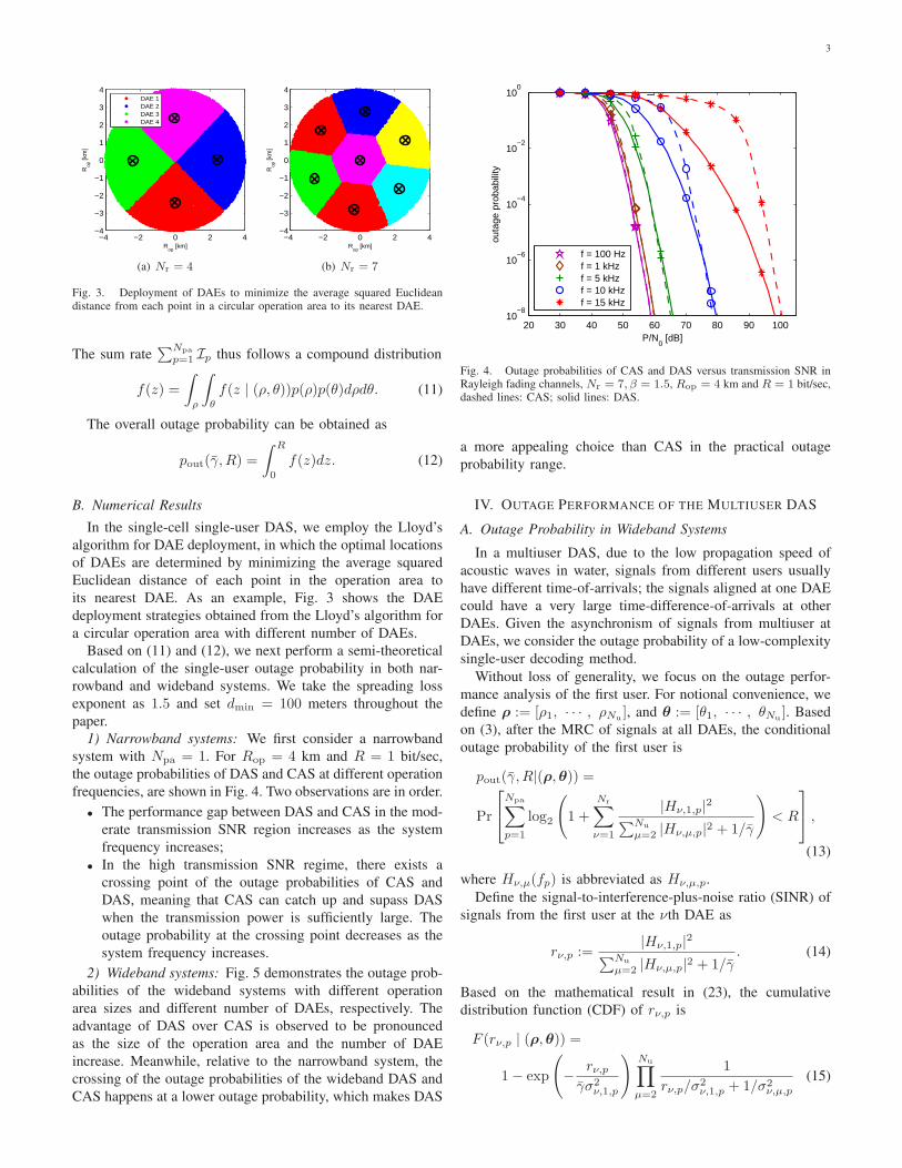
1) Narrowband systems: We first consider a narrowband
system with Npa = 1. For Rop = 4 km and R = 1 bit/sec,
the outage probabilities of DAS and CAS at different operation
frequencies, are shown in Fig. 4. Two observations are in order.
• The performance gap between DAS and CAS in the mod-
erate transmission SNR region increases as the system
frequency increases;
• In the high transmission SNR regime, there exists a
crossing point of the outage probabilities of CAS and
DAS, meaning that CAS can catch up and supass DAS
when the transmission power is sufficiently large. The
outage probability at the crossing point decreases as the
system frequency increases.
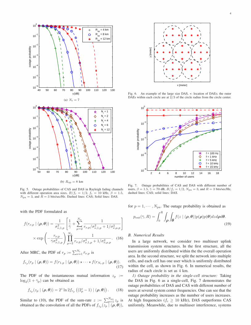
2) Wideband systems: Fig. 5 demonstrates the outage prob-
abilities of the wideband systems with different operation
area sizes and different number of DAEs, respectively. The
advantage of DAS over CAS is observed to be pronounced
as the size of the operation area and the number of DAE
increase. Meanwhile, relative to the narrowband system, the
crossing of the outage probabilities of the wideband DAS and
CAS happens at a lower outage probability, which makes DAS
20 30 40 50 60 70 80 90 10010
−8
10−6
10−4
10−2
100
P/N0 [dB]
outa
ge p
roba
bilit
y
f = 100 Hzf = 1 kHzf = 5 kHzf = 10 kHzf = 15 kHz
Fig. 4. Outage probabilities of CAS and DAS versus transmission SNR inRayleigh fading channels, Nr = 7, β = 1.5, Rop = 4 km and R = 1 bit/sec,dashed lines: CAS; solid lines: DAS.
a more appealing choice than CAS in the practical outage
probability range.
IV. OUTAGE PERFORMANCE OF THE MULTIUSER DAS
A. Outage Probability in Wideband Systems
In a multiuser DAS, due to the low propagation speed of
acoustic waves in water, signals from different users usually
have different time-of-arrivals; the signals aligned at one DAE
could have a very large time-difference-of-arrivals at other
DAEs. Given the asynchronism of signals from multiuser at
DAEs, we consider the outage probability of a low-complexity
single-user decoding method.
Without loss of generality, we focus on the outage perfor-
mance analysis of the first user. For notional convenience, we
define ρ := [ρ1, · · · , ρNu], and θ := [θ1, · · · , θNu
]. Based
on (3), after the MRC of signals at all DAEs, the conditional
outage probability of the first user is
pout(γ̄, R|(ρ,θ)) =
Pr
Npa∑
p=1
log2
(
1 +
Nr∑
ν=1
|Hν,1,p|2
∑Nu
µ=2 |Hν,µ,p|2 + 1/γ̄
)
< R
,
(13)
where Hν,µ(fp) is abbreviated as Hν,µ,p.
Define the signal-to-interference-plus-noise ratio (SINR) of
signals from the first user at the νth DAE as
rν,p :=|Hν,1,p|
2
∑Nu
µ=2 |Hν,µ,p|2 + 1/γ̄. (14)
Based on the mathematical result in (23), the cumulative
distribution function (CDF) of rν,p is
F (rν,p | (ρ,θ)) =
1− exp
(
−rν,p
γ̄σ2ν,1,p
)
Nu∏
µ=2
1
rν,p/σ2ν,1,p + 1/σ2
ν,µ,p
(15)
4
40 50 60 70 80 90 100 110 120 13010
−6
10−5
10−4
10−3
10−2
10−1
100
γ [dB]
outa
ge p
roba
bilit
y
R
op = 4 km
Rop
= 8 km
Rop
= 12 km
(a) Nr = 7
50 60 70 80 90 100 110 120 13010
−6
10−5
10−4
10−3
10−2
10−1
100
γ [dB]
outa
ge p
roba
bilit
y
N
r = 1
Nr = 2
Nr = 4
Nr = 6
Nr = 12
(b) Rop = 8 km
Fig. 5. Outage probabilities of CAS and DAS in Rayleigh fading channelswith different operation area sizes, B/fc = 1/2, fc = 10 kHz, β = 1.5,Npa = 3, and R = 3 bits/sec/Hz. Dashed lines: CAS; Solid lines: DAS.
with the PDF formulated as
f(rν,p | (ρ,θ)) =1
σ2ν,1,p
[
1
γ̄+
Nu∑
µ=2
1
rν,p/σ2ν,1,p + 1/σ2
ν,µ,p
]
× exp
(
−rν,p
γ̄σ2ν,1,p
)
Nu∏
µ=2
1
rν,p/σ2ν,1,p + 1/σ2
ν,µ,p
. (16)
After MRC, the PDF of rp :=∑Nr
ν=1 r̄ν,p is
frp(rp | (ρ,θ)) = f(r1,p | (ρ,θ)) ⋆ · · · ⋆ f(rNr,p | (ρ,θ)).(17)
The PDF of the instantaneous mutual information zp :=log2(1 + γ̄p) can be obtained as
fzp(zp | (ρ,θ)) = 2z ln 2frp(
(2zp − 1) | (ρ,θ))
. (18)
Similar to (10), the PDF of the sum-rate z :=∑Npa
p=1 zp is
obtained as the convolution of all the PDFs of fzp(zp | (ρ,θ)),
x [meter]
y [m
eter
]
Fig. 6. An example of the large size DAS, ∗: location of DAEs; the outerDAEs within each circle are at 2/3 of the circle radius from the circle center.
2 4 6 8 10 12 14 16 1810
−8
10−6
10−4
10−2
100
number of users
outa
ge p
roba
bilit
y
f = 100 Hzf = 1 kHzf = 5 kHzf = 10 kHzf = 15 kHz
Fig. 7. Outage probabilities of CAS and DAS with different number ofusers, β = 1.5, γ̄ = 70 dB, B/fc = 1/2, Npa = 3, and R = 3 bits/sec/Hz,dashed lines: CAS; solid lines: DAS.
for p = 1, · · · , Npa. The outage probability is obtained as
pout(γ̄, R) =
∫ R
0
∫
ρ
∫
θf(z | (ρ,θ))p(ρ)p(θ)dzdρdθ.
(19)
B. Numerical Results
In a large network, we consider two multiuser uplink
transmission system structures. In the first structure, all the
users are uniformly distributed within the the overall operation
area. In the second structure, we split the network into multiple
cells, and each cell has one user which is uniformly distributed
within the cell, as shown in Fig. 6. In numerical results, the
radius of each circle is set as 4 km.
1) Outage probability in the single-cell structure: Taking
the DAS in Fig. 6 as a single-cell, Fig. 7 demonstrates the
outage probabilities of DAS and CAS with different number of
users at several system center frequencies. One can see that the
outage probability increases as the number of users increases.
At high frequencies (fc ≥ 10 kHz), DAS outperforms CAS
uniformly. Meanwhile, due to multiuser interference, systems
5
40 50 60 70 80 90 100
10−8
10−6
10−4
10−2
100
γ [dB]
outa
ge p
roba
bilit
y
f = 5 kHzf = 10 kHzf = 15 kHz
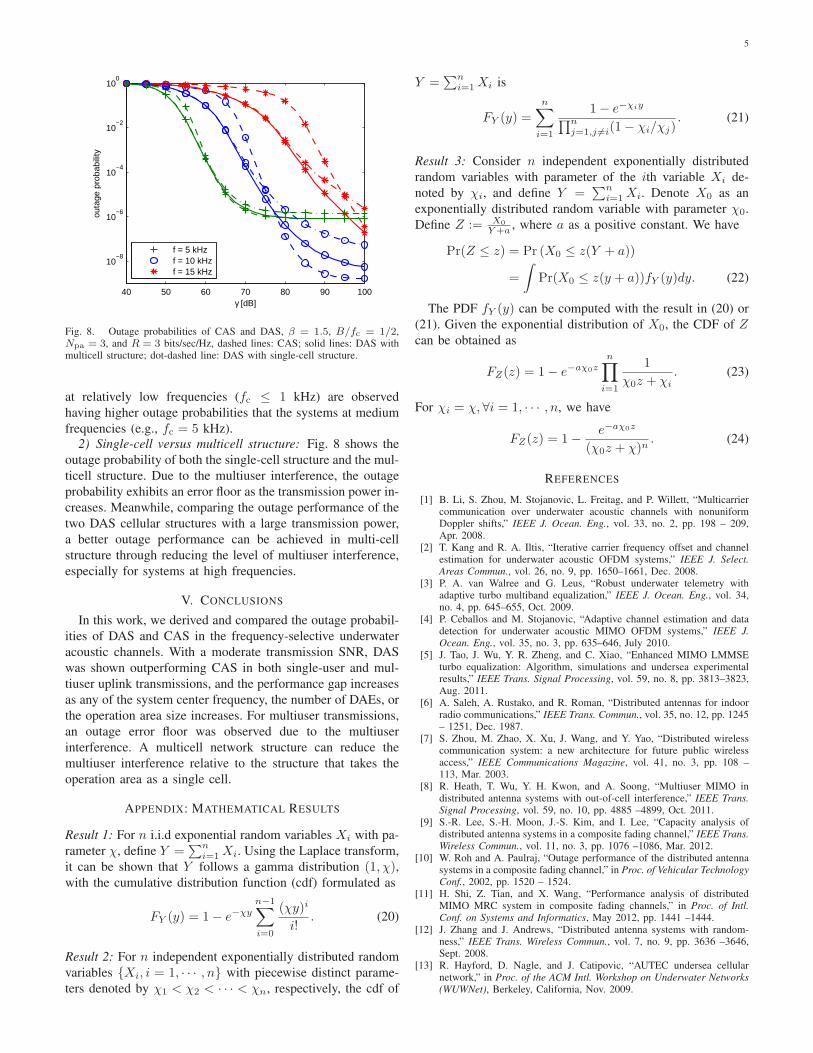
Fig. 8. Outage probabilities of CAS and DAS, β = 1.5, B/fc = 1/2,Npa = 3, and R = 3 bits/sec/Hz, dashed lines: CAS; solid lines: DAS withmulticell structure; dot-dashed line: DAS with single-cell structure.
at relatively low frequencies (fc ≤ 1 kHz) are observed
having higher outage probabilities that the systems at medium
frequencies (e.g., fc = 5 kHz).
2) Single-cell versus multicell structure: Fig. 8 shows the
outage probability of both the single-cell structure and the mul-
ticell structure. Due to the multiuser interference, the outage
probability exhibits an error floor as the transmission power in-
creases. Meanwhile, comparing the outage performance of the
two DAS cellular structures with a large transmission power,
a better outage performance can be achieved in multi-cell
structure through reducing the level of multiuser interference,
especially for systems at high frequencies.
V. CONCLUSIONS
In this work, we derived and compared the outage probabil-
ities of DAS and CAS in the frequency-selective underwater
acoustic channels. With a moderate transmission SNR, DAS
was shown outperforming CAS in both single-user and mul-
tiuser uplink transmissions, and the performance gap increases
as any of the system center frequency, the number of DAEs, or
the operation area size increases. For multiuser transmissions,
an outage error floor was observed due to the multiuser
interference. A multicell network structure can reduce the
multiuser interference relative to the structure that takes the
operation area as a single cell.
APPENDIX: MATHEMATICAL RESULTS
Result 1: For n i.i.d exponential random variables Xi with pa-
rameter χ, define Y =∑n
i=1 Xi. Using the Laplace transform,
it can be shown that Y follows a gamma distribution (1, χ),with the cumulative distribution function (cdf) formulated as
FY (y) = 1− e−χy
n−1∑
i=0
(χy)i
i!. (20)
Result 2: For n independent exponentially distributed random
variables {Xi, i = 1, · · · , n} with piecewise distinct parame-
ters denoted by χ1 < χ2 < · · · < χn, respectively, the cdf of
Y =∑n
i=1 Xi is
FY (y) =n∑
i=1
1− e−χiy
∏nj=1,j 6=i(1− χi/χj)
. (21)
Result 3: Consider n independent exponentially distributed
random variables with parameter of the ith variable Xi de-
noted by χi, and define Y =∑n
i=1 Xi. Denote X0 as an
exponentially distributed random variable with parameter χ0.
Define Z := X0
Y+a, where a as a positive constant. We have
Pr(Z ≤ z) = Pr (X0 ≤ z(Y + a))
=
∫
Pr(X0 ≤ z(y + a))fY (y)dy. (22)
The PDF fY (y) can be computed with the result in (20) or
(21). Given the exponential distribution of X0, the CDF of Zcan be obtained as
FZ(z) = 1− e−aχ0z
n∏
i=1
1
χ0z + χi
. (23)
For χi = χ, ∀i = 1, · · · , n, we have
FZ(z) = 1−e−aχ0z
(χ0z + χ)n. (24)
REFERENCES
[1] B. Li, S. Zhou, M. Stojanovic, L. Freitag, and P. Willett, “Multicarriercommunication over underwater acoustic channels with nonuniformDoppler shifts,” IEEE J. Ocean. Eng., vol. 33, no. 2, pp. 198 – 209,Apr. 2008.
[2] T. Kang and R. A. Iltis, “Iterative carrier frequency offset and channelestimation for underwater acoustic OFDM systems,” IEEE J. Select.
Areas Commun., vol. 26, no. 9, pp. 1650–1661, Dec. 2008.[3] P. A. van Walree and G. Leus, “Robust underwater telemetry with
adaptive turbo multiband equalization,” IEEE J. Ocean. Eng., vol. 34,no. 4, pp. 645–655, Oct. 2009.
[4] P. Ceballos and M. Stojanovic, “Adaptive channel estimation and datadetection for underwater acoustic MIMO OFDM systems,” IEEE J.
Ocean. Eng., vol. 35, no. 3, pp. 635–646, July 2010.[5] J. Tao, J. Wu, Y. R. Zheng, and C. Xiao, “Enhanced MIMO LMMSE
turbo equalization: Algorithm, simulations and undersea experimentalresults,” IEEE Trans. Signal Processing, vol. 59, no. 8, pp. 3813–3823,Aug. 2011.
[6] A. Saleh, A. Rustako, and R. Roman, “Distributed antennas for indoorradio communications,” IEEE Trans. Commun., vol. 35, no. 12, pp. 1245– 1251, Dec. 1987.
[7] S. Zhou, M. Zhao, X. Xu, J. Wang, and Y. Yao, “Distributed wirelesscommunication system: a new architecture for future public wirelessaccess,” IEEE Communications Magazine, vol. 41, no. 3, pp. 108 –113, Mar. 2003.
[8] R. Heath, T. Wu, Y. H. Kwon, and A. Soong, “Multiuser MIMO indistributed antenna systems with out-of-cell interference,” IEEE Trans.
Signal Processing, vol. 59, no. 10, pp. 4885 –4899, Oct. 2011.[9] S.-R. Lee, S.-H. Moon, J.-S. Kim, and I. Lee, “Capacity analysis of
distributed antenna systems in a composite fading channel,” IEEE Trans.
Wireless Commun., vol. 11, no. 3, pp. 1076 –1086, Mar. 2012.[10] W. Roh and A. Paulraj, “Outage performance of the distributed antenna
systems in a composite fading channel,” in Proc. of Vehicular Technology
Conf., 2002, pp. 1520 – 1524.[11] H. Shi, Z. Tian, and X. Wang, “Performance analysis of distributed
MIMO MRC system in composite fading channels,” in Proc. of Intl.
Conf. on Systems and Informatics, May 2012, pp. 1441 –1444.[12] J. Zhang and J. Andrews, “Distributed antenna systems with random-
ness,” IEEE Trans. Wireless Commun., vol. 7, no. 9, pp. 3636 –3646,Sept. 2008.
[13] R. Hayford, D. Nagle, and J. Catipovic, “AUTEC undersea cellularnetwork,” in Proc. of the ACM Intl. Workshop on Underwater Networks
(WUWNet), Berkeley, California, Nov. 2009.
6
[14] A. Proctor, J. Kennedy, E. Gamroth, C. Bradley, and D. Gamroth, “Theocean technology test bed - From concept to operation,” in Proc. of
MTS/IEEE OCEANS Conf., Sept. 2010.


![Nonlinear Multi-Antenna Detection Methods · multiuser detection designed for code-division multiple-access (CDMA) [16]–[20]. In fact, it has been observed even in linearly separable](https://img.dokumen.tips/doc/110x75/603db2432ffb6326e07b3a30/nonlinear-multi-antenna-detection-methods-multiuser-detection-designed-for-code-division.jpg)