Embed Size (px)
Citation preview
1
Out-of-Plane Magnetic Actuators with Electroplated Permalloy
for Fluid Dynamics Control
Chang Liu, Thomas Tsao+, Gwo-Bin Lee**, Jeremy T.S. Leu*, Yong W. Yi, Yu-Chong Tai+,
& Chih-Ming Ho*
Micro Actuators, Sensors, and Systems (MASS) Group,University of Illinois at Urbana-Champaign
Urbana, IL 618011
+Electrical Engineering, California Institute of Technology, Pasadena, CA 9125
*Mechanical, Aerospace and Nuclear Engineering, University of California at Los AngelesLos Angeles, CA 90024
** Engineering Science, National Cheng Kung University, Tainan, Taiwan, Republic of China,
Keywords: magnetic actuation, Permalloy, fluid control.
1 Address of the corresponding author: Chang Liu, 313 Microelectronics Laboratory, 208 North WrightStreet, Urbana, IL 61801, USA. Phone: 217-333-4051. Email: [email protected].
2
ABSTRACT
We have developed millimeter-scaled magnetic actuators capable of achieving large out-
of-plane displacement and large forces using surface micromachining techniques in
conjunction with electroplating of Permalloy (Ni80Fe20). Each actuator consists of a
Permalloy piece attached to flexural cantilever beams, which are 400-µm long and 100-
µm wide. Experiments show that, under a 6x10⁴-A/m external magnetic field, an
actuator with the volume of the magnetic piece being 1 mm % 1 mm % 5 µm can reach a
65o angular displacement and exert a 87-µN force in the direction perpendicular to the
substrate. We also discuss one potential application of controlling macroscopic fluidic
mechanical systems using micromachined actuators. Results on using developed
actuators to achieve rolling motion in a macro-scaled delta-wing airfoil are presented.
3
I. INTRODUCTION
Technologies for developing micromachined actuators have been advanced significantly in the
past two decades. However, to achieve large output force (on the order of tens of µN) and
long actuation range (100 µm and above) in micro electromechanical systems (MEMS)
still poses many challenges. The electrostatic actuation, which is widely used in MEMS
actuators, can not always satisfy the desired range of force and displacement
simultaneously under the constraints of practical micro systems. Other actuation
methods, such as ones based on bi-metallic thermal actuation or shape memory alloy
materials, are capable of producing the required displacement and force; however, their
actuation capabilities are limited by the required temperature.
Micro fabricated actuators are being increasingly used for fluid-control purposes. For
these applications, a large force is required in order to allow efficient interaction with the
fluid and to generate desired control effects. Magnetic actuation is potentially capable of
realizing both large force and large displacement in an energy-efficient manner [1-3].
Wagner et al. [4] manually attached miniature permanent-magnet pieces on
microfabricated suspensions and utilized integrated in-plane coils on the same chip to
generate an external magnetic field. Liu et al. developed an integrated coil-type magnetic
actuator capable of achieving out-of-plane rotational displacement on the order of several
hundred micrometers and magnetic forces with magnitude in the 10's of µN range [5].
However, coil-type actuators typically require large biasing current (typically 50 mA)
which, when coupled with a large number of turns in the coil, can translate into rather
4
significant ohmic-heating. Judy et al. demonstrated in-plane motion of a suspended
polycrystalline silicon structure with an electroplated magnetic piece [6]. The actuator
was driven by an external magnetic field and large deflection angle (over 180o) has been
demonstrated. In addition, Miller et al. [7] and Judy et al. [8] have both developed
individually addressable magnetic actuators. Moreover, complex electromagnetic sub-
systems, including a planar electromagnet [2] and magnetic micromotors [3], have also
been realized in the past.
II. FLUID DYNAMICAL APPLICATIONS
Micromachined actuators have traditionally been used to control objects with similar or
smaller dimensions or mass. Examples of these applications include micro fluidic
devices, micro assembly [9] and mirrors for optical beam steering. As a novel objective
of our current project, we plan to demonstrate that a collection of micro-machined
actuators can control macro-scale objects, provided that a proper controlling mechanism
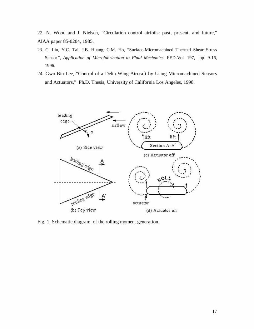
exists [10]. The macro object is a delta-wing airfoil, which is one of the fundamental
configurations for generating lift forces [11, 12]. Though the sizes of micro actuators are
much smaller compared with that of the delta-wing, there exists a known fluid
mechanism that allows micro-scale actuation to have an amplified, macroscopic effects
(Fig. 1).
When laminar air flow impinges on the two leading edges of the wing at a certain angle-
of-attack (Fig. 1a&b), two counter-rotating leading-edge vortices separate from the
5
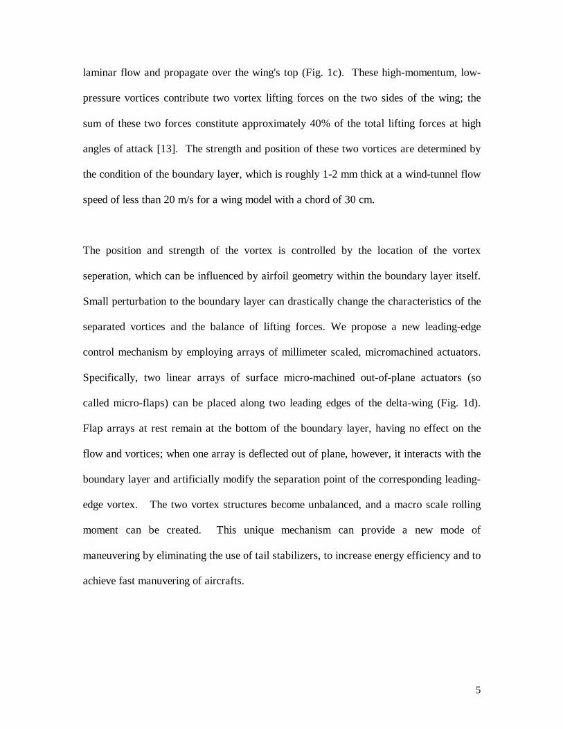
laminar flow and propagate over the wing's top (Fig. 1c). These high-momentum, low-
pressure vortices contribute two vortex lifting forces on the two sides of the wing; the
sum of these two forces constitute approximately 40% of the total lifting forces at high
angles of attack [13]. The strength and position of these two vortices are determined by
the condition of the boundary layer, which is roughly 1-2 mm thick at a wind-tunnel flow
speed of less than 20 m/s for a wing model with a chord of 30 cm.
The position and strength of the vortex is controlled by the location of the vortex
seperation, which can be influenced by airfoil geometry within the boundary layer itself.
Small perturbation to the boundary layer can drastically change the characteristics of the
separated vortices and the balance of lifting forces. We propose a new leading-edge
control mechanism by employing arrays of millimeter scaled, micromachined actuators.
Specifically, two linear arrays of surface micro-machined out-of-plane actuators (so
called micro-flaps) can be placed along two leading edges of the delta-wing (Fig. 1d).
Flap arrays at rest remain at the bottom of the boundary layer, having no effect on the
flow and vortices; when one array is deflected out of plane, however, it interacts with the
boundary layer and artificially modify the separation point of the corresponding leading-
edge vortex. The two vortex structures become unbalanced, and a macro scale rolling
moment can be created. This unique mechanism can provide a new mode of
maneuvering by eliminating the use of tail stabilizers, to increase energy efficiency and to
achieve fast manuvering of aircrafts.

6
In this study, micromachined actuators are required to deflect 1 to 2 mm out-of-plane
(comparable with the thickness of boundary layers), and withstand large aerodynamic
loading on the order of several hundred µN. Microactuators can potentially sustain high
fluid loading because they reside in boundary layers, in which the flow velocity and
momentum is lowered compared with the free stream. These offer much higher
mechanical response speed compared with macroscopic mechanical elements.
III. ACTUATOR DESIGN
Figure 2 illustrates the schematic diagram of a micromachined magnetic actuator, which
consists of a suspended magnetic piece. Its length, width, and thickness are designated as
L, W, and T, respectively. The magnetic piece is supported by two cantilever beams, with
their length, width, and thickness being l, w, and t, respectively. The bending
displacement of the actuator due to its own gravitational weight is negligibly small.
The analysis of displacement as a function of the applied magnetic field is presented in
the following. Since the regime of large angular displacement is the focus of our design,
the Permalloy is modeled as a permanent magnet with the magnitude of its magnitization
vector being equal to the saturation magnetization, Ms. It should be noted, however, that
under low magnetic field and angular displacement, the magnetization is not a constant
but changes according to the applied magnetic field strength. Discussion of this topic can
be found in [8].
7
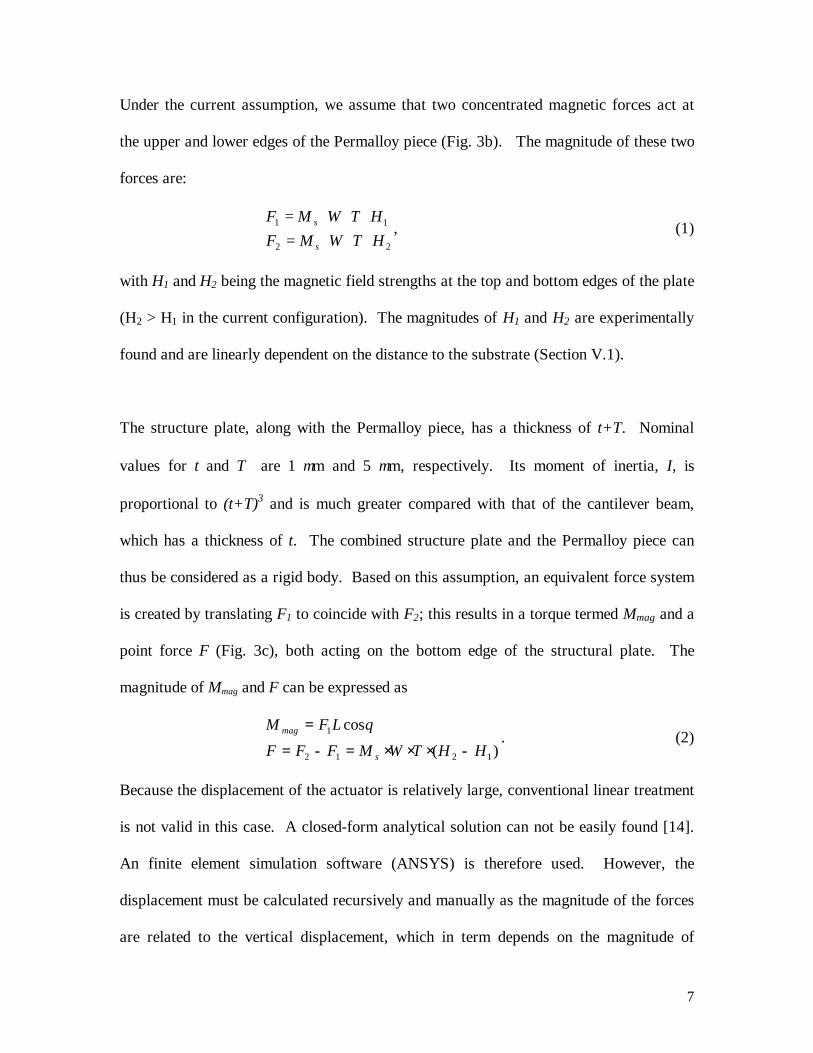
Under the current assumption, we assume that two concentrated magnetic forces act at
the upper and lower edges of the Permalloy piece (Fig. 3b). The magnitude of these two
forces are:
22
11
HTWMFHTWMF
s
s
⋅⋅⋅=⋅⋅⋅=
, (1)
with H1 and H2 being the magnetic field strengths at the top and bottom edges of the plate
(H2 > H1 in the current configuration). The magnitudes of H1 and H2 are experimentally
found and are linearly dependent on the distance to the substrate (Section V.1).
The structure plate, along with the Permalloy piece, has a thickness of t+T. Nominal
values for t and T are 1 µm and 5 µm, respectively. Its moment of inertia, I, is
proportional to (t+T)3 and is much greater compared with that of the cantilever beam,
which has a thickness of t. The combined structure plate and the Permalloy piece can
thus be considered as a rigid body. Based on this assumption, an equivalent force system
is created by translating F1 to coincide with F2; this results in a torque termed Mmag and a
point force F (Fig. 3c), both acting on the bottom edge of the structural plate. The
magnitude of Mmag and F can be expressed as
)(
cos
1212
1
HHTWMFFF
LFM
s
mag
−⋅⋅⋅=−== θ
. (2)
Because the displacement of the actuator is relatively large, conventional linear treatment
is not valid in this case. A closed-form analytical solution can not be easily found [14].
An finite element simulation software (ANSYS) is therefore used. However, the
displacement must be calculated recursively and manually as the magnitude of the forces
are related to the vertical displacement, which in term depends on the magnitude of
8
forces. The calculation process is inefficient. We are therefore motivated to find a
simplified analytical solution.
Using the ANSYS finite element simulation, we have found that it is a good
approximation to treat the displacements due to the moment and the force independantly
and add these results to calculate the actuator bending under the combined force and
momentum. This assumption is valid when the force is relatively small. It significantly
simplifies the analysis.
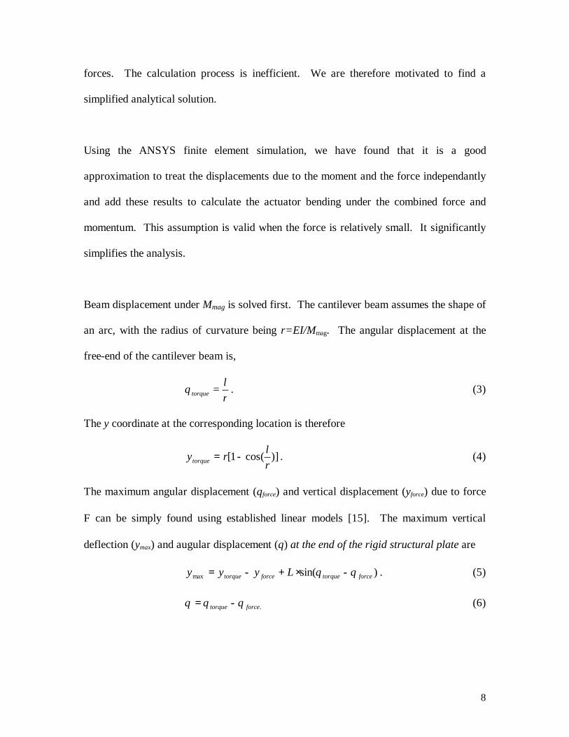
Beam displacement under Mmag is solved first. The cantilever beam assumes the shape of
an arc, with the radius of curvature being r=EI/Mmag. The angular displacement at the
free-end of the cantilever beam is,
rl
torque =θ . (3)
The y coordinate at the corresponding location is therefore
)]cos(1[rlrytorque −= . (4)
The maximum angular displacement (θforce) and vertical displacement (yforce) due to force
F can be simply found using established linear models [15]. The maximum vertical
deflection (ymax) and augular displacement (θ) at the end of the rigid structural plate are
)sin(max forcetorqueforcetorque Lyyy θθ −⋅+−= . (5)
.forcetorque θθθ −= (6)
9
We have designed the area of the Permalloy piece to be 1 by 1 mm2. The supporting
cantilever beams are 400-µm long and 100-µm wide, with the nominal thickness being 1
µm.
IV. FABRICATION PROCESS
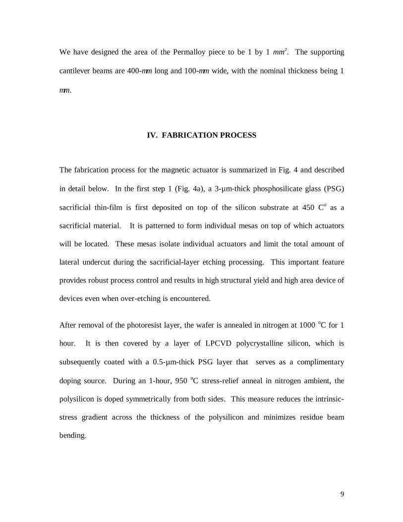
The fabrication process for the magnetic actuator is summarized in Fig. 4 and described
in detail below. In the first step 1 (Fig. 4a), a 3-µm-thick phosphosilicate glass (PSG)
sacrificial thin-film is first deposited on top of the silicon substrate at 450 Co as a
sacrificial material. It is patterned to form individual mesas on top of which actuators
will be located. These mesas isolate individual actuators and limit the total amount of
lateral undercut during the sacrificial-layer etching processing. This important feature
provides robust process control and results in high structural yield and high area device of
devices even when over-etching is encountered.
After removal of the photoresist layer, the wafer is annealed in nitrogen at 1000 oC for 1
hour. It is then covered by a layer of LPCVD polycrystalline silicon, which is
subsequently coated with a 0.5-µm-thick PSG layer that serves as a complimentary
doping source. During an 1-hour, 950 oC stress-relief anneal in nitrogen ambient, the
polysilicon is doped symmetrically from both sides. This measure reduces the intrinsic-
stress gradient across the thickness of the polysilicon and minimizes residue beam
bending.
10
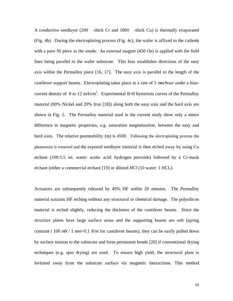
A conductive seedlayer (200 å-thick Cr and 1800 å-thick Cu) is thermally evaporated
(Fig. 4b). During the electroplating process (Fig. 4c), the wafer is affixed to the cathode
with a pure Ni piece as the anode. An external magnet (450 Oe) is applied with the field
lines being parallel to the wafer substrate. This bias establishes directions of the easy
axis within the Permalloy piece [16, 17]. The easy axis is parallel to the length of the
cantilever support beams. Electroplating takes place at a rate of 5 µm/hour under a bias-
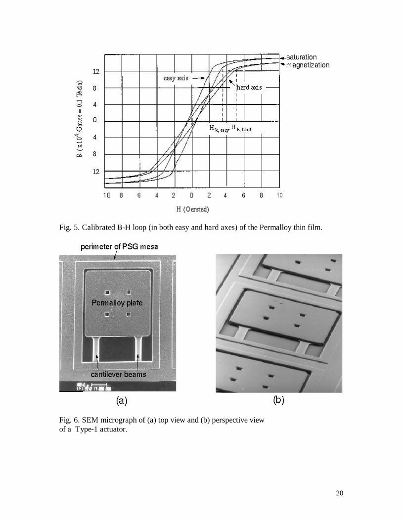
current density of 8 to 12 mA/cm2. Experimental B-H hysteresis curves of the Permalloy
material (80% Nickel and 20% Iron [18]) along both the easy axis and the hard axis are
shown in Fig. 5. The Permalloy material used in the current study show only a minor
difference in magnetic properties, e.g. saturation magnetization, between the easy and
hard axes. The relative peameability (µr) is 4500. Following the electroplating process the
photoresist is removed and the exposed seedlayer material is then etched away by using Cu
etchant (100:5:5 wt. water: acetic acid: hydrogen peroxide) followed by a Cr-mask
etchant (either a commercial etchant [19] or diluted HCl (10 water: 1 HCL).
Actuators are subsequently released by 49% HF within 20 minutes. The Permalloy
material sustains HF etching without any structural or chemical damage. The polysilicon
material is etched slightly, reducing the thickness of the cantilever beams. Since the
structure plates have large surface areas and the supporting beams are soft (spring
constant i100 µN / 1 mm=0.1 N/m for cantilever beams), they can be easily pulled down
by surface tension to the substrate and form permanent bonds [20] if conventional drying
techniques (e.g. spin drying) are used. To ensure high yield, the structural plate is
levitated away from the substrate surface via magnetic interactions. This method

11
effectively prevents the actuators from coming into contact with the substrate, therefore
guaranteeing that 100% yield is routinely achieved. Shown in Fig. 6 are top and
perspective views of fabricated actuators.
V. RESULTS AND DISCUSSIONS
V.1. Actuator Calibration in Still Air
We used an electromagnet to provide an uniform external magnetic field. The variation
of H with respect to the distance, d, to the substrate plane, is calibrated experimentally
using a Gauss meter (Edmund Scientific Inc.). In a region near the surface of the core, H
decreases linearly with increasing spacing d, according to the following expression,
),1(0 dHH ⋅−= α (7)
where H0 is the strength of the magnetic field at the surface of the substrate, α is a scaling
constant (α=0.0267 as determined by calibration).
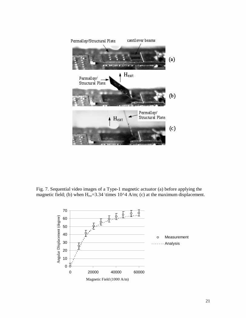
Figure 7 contains a sequence of video images of an actuator at the resting and the
activated positions. Fig. 8 shows the measured magnitude of angular displacements
together with the results obtained by analysis. The magnetization of the material is 1.5 T
as determined by the measurement (Fig. 5). Due to small but finite etching of polysilicon
by the HF solutions, the thickness of the cantilever beams is 9700 Å.instead of 1 µm.

12
We have demonstrated that the beams can be bent by more than 180o without failure. In
pure bending mode, the support cantilever beams may be fractured when the maximum
normal strain (near the surface at its fixed end) exceeds the fracture strain of the beam
material. For polysilicon, fracture strain equals 3103.9 −× according to an early report by
Tai et al. [21].
V.2. Fluid Dynamic Control
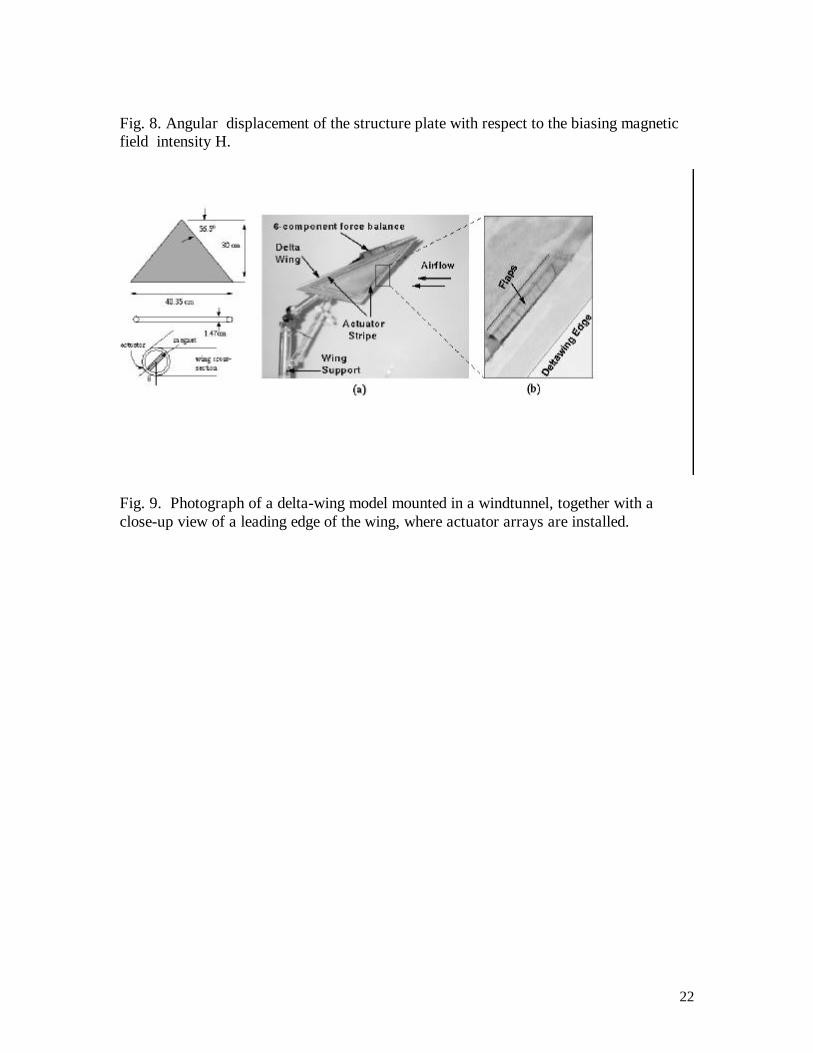
A scaled aluminum delta-wing airfoil (Fig. 9) has a span of 40.35 cm and a sweep angle
of 56.5o. It is mounted on a 6-component transducer that records moments and forces in
three axes. The magnetic biasing is provided by a rotational magnetic bar embedded
within the leading edges of the delta wing and powered by a miniature stepping motor.
The location of the actuators is indicated by the angle β which is zero at the lower surface
and 180o at the upper surface of the wing.
It was found that the region close to flow separation is very sensitive to small
perturbation [22]. The innovation of this study is applying micro actuators to manipulate
the thin boundary layer near the leading edges of a delta wing, and consequently, alter the
flow separation location. We used a micromachined shear-stress sensor [23] to measure
the separation point along the leading edges of the delta wing.
Initially, time-averaged measurement of the rolling moment Mroll was taken with the flaps
kept on for at least four minutes. The resulting Mroll at different wind-tunnel flow speed

13
is normalized with respect to the vortex lift moment, Mvl. Since only a single vortex is
controlled, the resulting Mroll at different wind-tunnel flow speed is normalized with
respect to the moment produced by a single vortex, Mvl. Here, Mvl is the product of the
vortex-lift force on one of the leading edges multiplied by the distance from the
centerline to the centroid of the half wing. The rolling moment is measured as a function
of β for various angles of attack α (α=20°, 25°, 30°, and 35°). The free-stream velocity
is also varied from 10 to 35 m/s. Approximately 15 % torque was achieved at an angle of
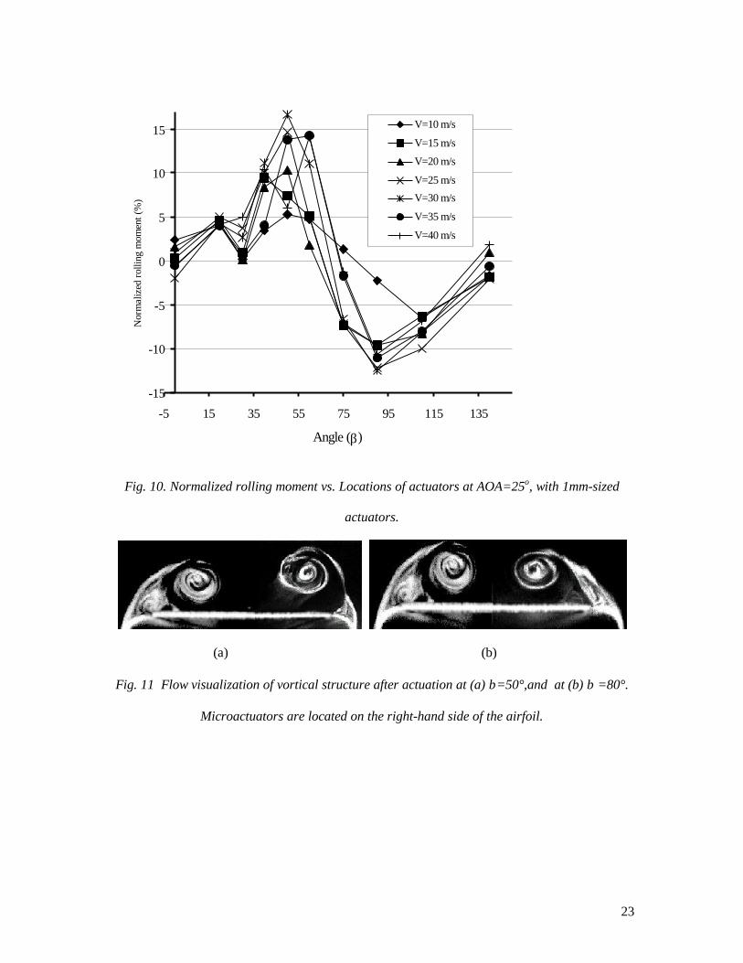
attack of 25o (Fig. 10). At α = 25o, a negative torque can be as large as -12% at β=80o.
The interaction between micro actuators and vortices can be seen from flow visualization
experiments [24] . Figure 11 (a) shows the vortex structure with an array of actuators
located at β=50° on the right-hand side of the wing. Also shown on the left-hand side in
Fig. 11 (a) is a picture of a single vortex without any actuator for comparison. It is clearly
noticeable that vortex structure has been distorted by the presence of the micro actuators.
Since the location of the micro actuators is ahead of the separation point, the flow could
separate earlier due to the higher pressure gradient caused by the presence of the micro
actuator. It was observed that the core of the vortex has been moved outboard. A positive
rolling moment could be generated by these unbalanced vortices.
At β>60o, the rolling moment becomes negative in all cases. Fig. 11 (b) is the flow
visualization picture of the vortex with a linear array of actuators located at β=80°. It was
found that the core of the vortex had shifted inboard and the direction of the shear layer
shedding from the leading edge had been suppressed. The possible mechanism for the
14
phenomena is as follows: the flap actuator moves away from the surface and reduces the
local curvature locally such that the adverse pressure gradient is reduced. As a result, the
separation is delayed and the vortex moves inboard. A negative rolling moment could be
generated by these unbalanced vortices accordingly. The negative rolling moment can be
employed in conjunction with the positive-working rolling moment generated on an
opposite leading edge. We have observed the sum of individual incremental torque
equals the value obtained by the simultaneous actuation along both leading edges; it
indicates that modifications of the vortices on both sides of a wing by the actuators seem
to be independent.
VI. CONCLUSIONS
Surface micro-machined out-of-plane Permalloy actuator arrays have been developed for
controlling the rolling moment of a tail-less delta wing. The actuator consists of a
millimeter sized electroplated Permalloy plate with supporting poly-silicon beams and is
driven by an external magnetic field. Large angular deflections (over 600) and vertical
deflections (on the order of 1-2 mm) have been demonstrated. The magnetic forces and
flow loading involved in the flap operation is on the order of hundred's of µN. Linear
arrays of such flaps are positioned near the leading edges of a delta wing; wind-tunnel
tests confirm that a rolling moment on the wing can be generated by the flap actuation.
These magnetic actuators can have a number of applications, including fluid mechanics
applications that are illustrated in this paper. Others include optical light modulators and
micro robotics assembly systems.
15
VII. ACKNOWLEDGEMENT
This work is supported by the Defense Advanced Research Program Agency. The
authors thank the many help and discussions from colleagues, including Drs. Steve Tung,
Weilong Tang, Raanan Miller, Fukang Jiang and Jin-Biao Huang, who were members of
the URI/DARPA team.
VIII. REFERENCES
1. I.J. Busch-Vishniac, “The case for magnetic actuators,” Sensors and Actuators, A 33,
pp. 207-220, 1992.
2. C.H. Ahn and M.G. Allen, “A fully integrated surface micromachined magnetic
microactuator with a multilevel meander magnetic core,” Journal of MEMS,Vol. 2(1),
pp. 15-22, 1993.
3. H. Guckel. T.R. Christenson, K.J. Skrobis, T.S. Jung, J. Klein, K.V. Hartojo and I.
Widjaja, “A first functional current excited planar rotational magnetic micromotor,”
1993 IEEE Workshop on Micro Electro Mechanical-Systems, pp. 7-11, 1993.
4. B. Wagner, W. Benecke, G. Engelmann and J. Simon, “Micro actuators with moving
magnets for linear, torsional or multi-axial motion,” Sensors and Actuators, A(32), pp.
598-603, 1992.
5. C. Liu, T. Tsao, Y.C. Tai and C.M. Ho, “Surface micromachined magnetic actuators,”
Technical Digest, 1994 IEEE Workshop on Micro-Electro-Mechanical-Systems, pp.
57-62, 1994.
6. J.W. Judy, R.S. Muller and H.H. Zappe, “Magnetic microactuation of polysilicon
flexure structures,” Journal of MEMS, Vol. 4, No. 4, pp. 162-169, 1995.
7. R. A. Miller, Y.C. Tai, G. Xu, J. Bartha and F. Lin, “An electromagnetic MEMS 2x2
fiber optic bypass switch,” 1997 International Conference on Solid-state sensors and
actuators, Chicago, IL, Vol. 1, pp. 89-92, 1997.
16
8. J. Judy and R.S. Muller, “Magnetically Actuated, addressable microstructures,”
Journal of MEMS, Vol. 6, No. 3, p. 257, 1997.
9. C. Liu, T.R. Tsao, Y.C. Tai, W. Liu, P. Will and C.M. Ho, "A micromachined
permalloy magnetic actuator array for micro robotics assembly systems,” 1995
International Conference on Solid-state sensors and actuators, Stockholm, Sweden,
Vol. 1, pp. 328-331, 1995.
10. C.M. Ho. and Y.C. Tai, 1996, “MEMS and Its Applications for Flow Control”, Journal of
Fluid Engineering, Sep. 1996.
11. W. Gu, O. Robinson, D. Rockwell, “Control of vortices on a deltawing by leading
edge injection,” AIAA Journal, Vol. 31, No. 7, pp. 1177-1186, 1993.
12. K. Rinoie, “Experiments on a 60-degree deltawing with vortex flaps and vortex
plates,” Aeronautical Journal, Vol. 97 (961), pp. 33-38, 1993.
13. M. Lee and C.M. Ho, “Lift Force of Delta Wings”, Applied Mechanics Reviews, Vol.
43, pp. 209-221, 1996.
14. R. Frisch-Fay, Flexible bars, Butterworths, London, 1962.
15. W.C. Young, Roark's Formulas for Stress and Strain, 6th Ed., McGraw-Hill, 1989.
16. M. Takahashi, "Induced magnetic anisotropy of evaporated films formed in a
magnetic field,” Journal of Applied Physics, Supplement to Vol. 33, No. 3, pp. 1101-
1106, 1962.
17. S. Abel, H. Freimuth, H. Lehr and H. Mensinger, “Defined crystal orientation of
Nickel by controlled microelectroplatings,” J. Micromechanics and
Microengineering, Vol. 4, pp. 47-54, 1994.
18. V. Temesvary, S. Wu, W.H. Hsieh, Y.C. Tai and D.K. Miu, “Design, fabrication and testing
of micromachined electromagnetic microactuators for rigid disk drives,” IEEE Journal of
MEMS, Vol. 4, No.1, pp. 18-27, 1995.
19. R.L. Alley, G.J. Cuan, R.T. Howe, K. Komvopoulos, “ The effect of release-etch processing
on surface microstructure stiction,” Proceedings, IEEE Solid-State sensor and Actuator
Workshop, Hilton Head, SC, USA, pp. 202-207, 1992.
20. Cr mask etchant, Transene Co., USA.
21. Y.C. Tai, R. S. Muller, “Fracture strain of LPCVD polysilicon,” Technical Digest,
IEEE Solid-State Sensors and Actuators Workshop, Hilton Head Island, SC, USA,
pp. 88-91, 1988.
17
22. N. Wood and J. Nielsen, "Circulation control airfoils: past, present, and future,"
AIAA paper 85-0204, 1985.
23. C. Liu, Y.C. Tai, J.B. Huang, C.M. Ho, “Surface-Micromachined Thermal Shear Stress
Sensor”, Application of Microfabrication to Fluid Mechanics, FED-Vol. 197, pp. 9-16,
1996.
24. Gwo-Bin Lee, “Control of a Delta-Wing Aircraft by Using Micromachined Sensors
and Actuators,” Ph.D. Thesis, University of California Los Angeles, 1998.
Fig. 1. Schematic diagram of the rolling moment generation.

18
Fig. 2. Schematic of a Permalloy magnetic actuator with two cantilever-beam supports.(a) Top view and (b) cross-sectional view.

19
Fig. 3. Schematic illustration of the mechanism of magnetic actuator biased using anexternal electromagnet. (a) Rest position of the actuator when the external magneticfield, Hext, equals 0; (b) out-of-plane actuation when Hext, <>0 is provided by an externalelectromagnet; (c) a simplified force system (containing Mmag and F) acting at the free-ends of the cantilever beams.
Fig. 4. Major fabrication steps of a Permalloy magnetic actuator.
20
Fig. 5. Calibrated B-H loop (in both easy and hard axes) of the Permalloy thin film.
Fig. 6. SEM micrograph of (a) top view and (b) perspective viewof a Type-1 actuator.
21
Fig. 7. Sequential video images of a Type-1 magnetic actuator (a) before applying themagnetic field; (b) when Hext=3.34 \times 10^4 A/m; (c) at the maximum displacement.
0
10
20
30
40
50
60
70
0 20000 40000 60000
Magnetic Field (1000 A/m)
Ang
ular
Dis
plac
emen
t (de
gree
)
Measurement
Analysis
22
Fig. 8. Angular displacement of the structure plate with respect to the biasing magneticfield intensity H.
Fig. 9. Photograph of a delta-wing model mounted in a windtunnel, together with aclose-up view of a leading edge of the wing, where actuator arrays are installed.
23
-15
-10
-5
0
5
10
15
-5 15 35 55 75 95 115 135
Angle (β)
Nor
mal
ized
rolli
ng m
omen
t (%
)V=10 m/s
V=15 m/s
V=20 m/s
V=25 m/s
V=30 m/s
V=35 m/s
V=40 m/s
Fig. 10. Normalized rolling moment vs. Locations of actuators at AOA=25o, with 1mm-sized
actuators.
(a) (b)
Fig. 11 Flow visualization of vortical structure after actuation at (a) β=50°,and at (b) β =80°.
Microactuators are located on the right-hand side of the airfoil.