Embed Size (px)
Citation preview
OS3 Fiber Day
Fiber to the Home technologyMay 21, 2014 / Erik Radius
GlasOperator / Vodafone
Contents (more or less)
• Optical fiber
– Inner workings
– Fiber types
– Transmitter, receiver
• Transmission
– Link budget calculations
• Optical networks
– Core, Metro, Access
• Architectures
• Access network scenarios
Why do we use light signals in networking?
3
let’s explain this with some
conductor physics
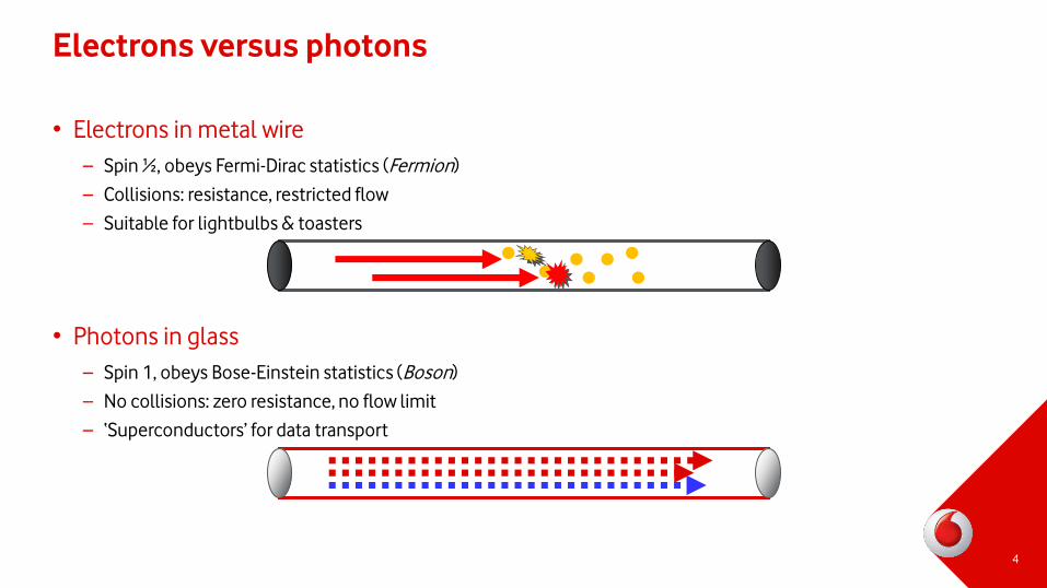
Electrons versus photons
• Electrons in metal wire
– Spin ½, obeys Fermi-Dirac statistics (Fermion)
– Collisions: resistance, restricted flow
– Suitable for lightbulbs & toasters
• Photons in glass
– Spin 1, obeys Bose-Einstein statistics (Boson)
– No collisions: zero resistance, no flow limit
– ‘Superconductors’ for data transport
4
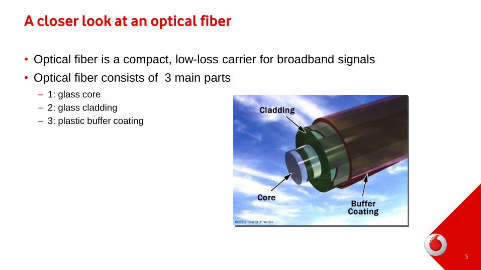
A closer look at an optical fiber
• Optical fiber is a compact, low-loss carrier for broadband signals
• Optical fiber consists of 3 main parts
– 1: glass core
– 2: glass cladding
– 3: plastic buffer coating
5
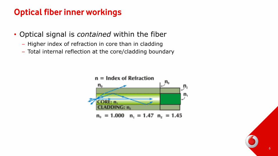
Optical fiber inner workings
• Optical signal is contained within the fiber
– Higher index of refraction in core than in cladding
– Total internal reflection at the core/cladding boundary
6
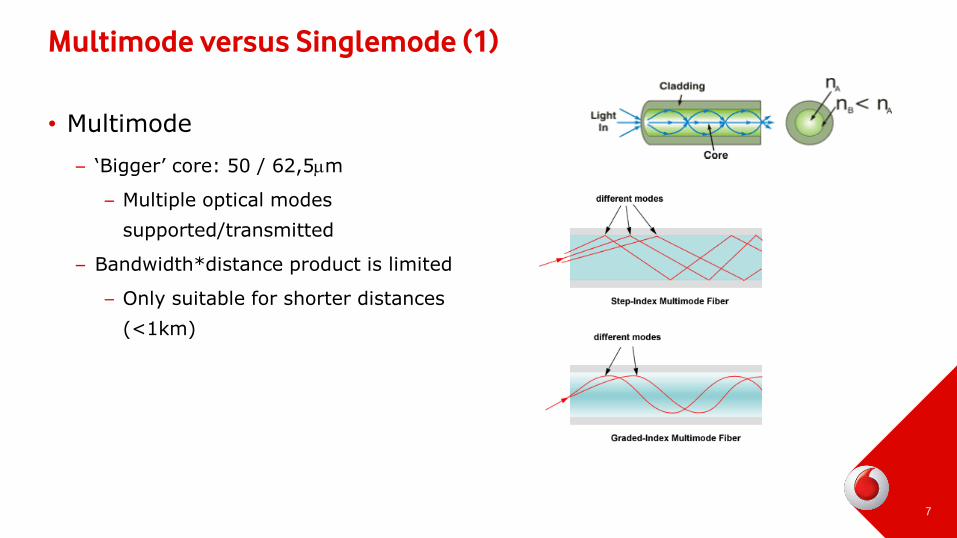
Multimode versus Singlemode (1)
• Multimode
– ‘Bigger’ core: 50 / 62,5mm
– Multiple optical modes
supported/transmitted
– Bandwidth*distance product is limited
– Only suitable for shorter distances
(<1km)
7
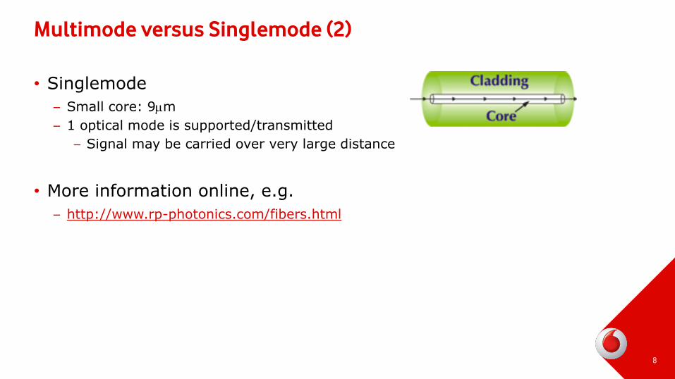
Multimode versus Singlemode (2)
• Singlemode
– Small core: 9mm
– 1 optical mode is supported/transmitted
– Signal may be carried over very large distance
• More information online, e.g.
– http://www.rp-photonics.com/fibers.html
8
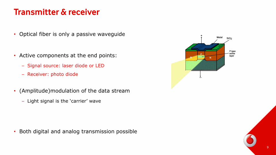
Transmitter & receiver
• Optical fiber is only a passive waveguide
• Active components at the end points:
– Signal source: laser diode or LED
– Receiver: photo diode
• (Amplitude)modulation of the data stream
– Light signal is the ‘carrier’ wave
• Both digital and analog transmission possible
9
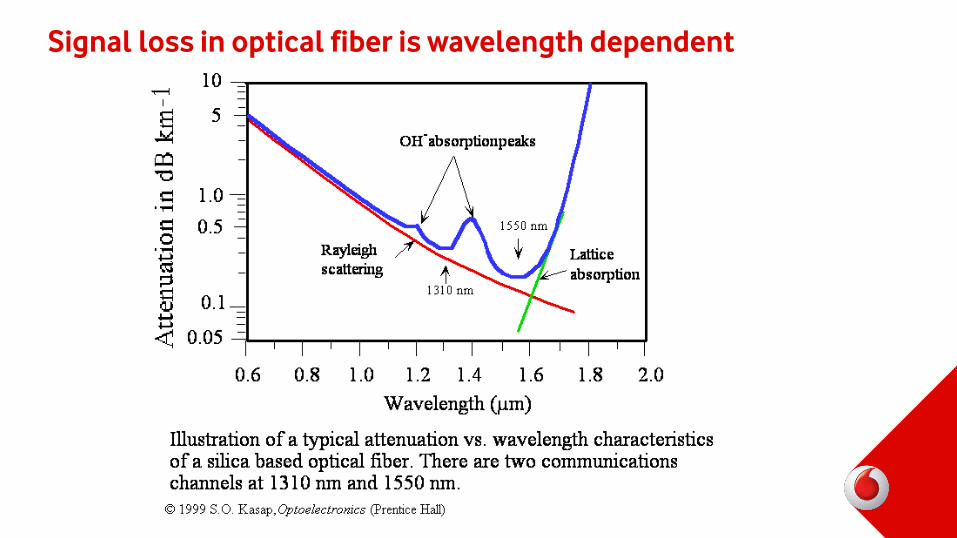
Signal loss in optical fiber is wavelength dependent
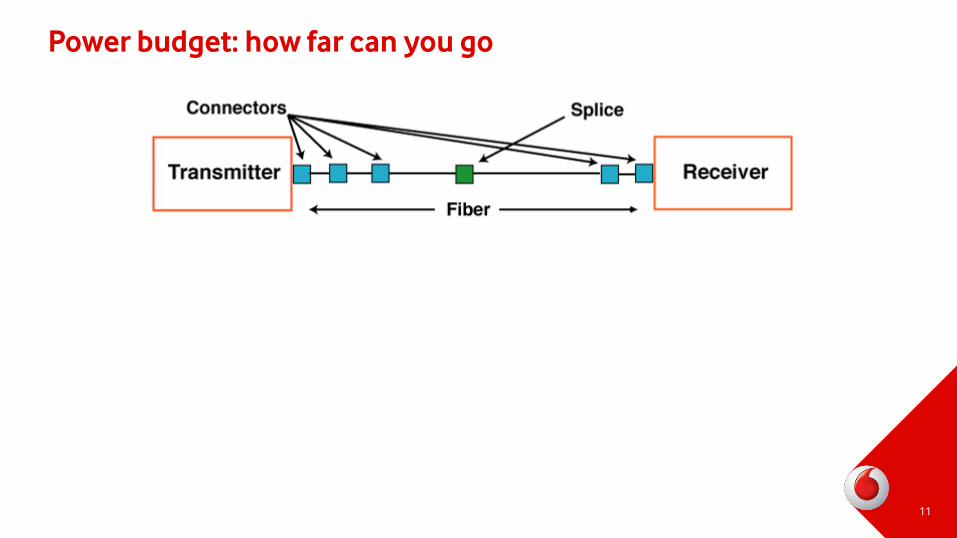
Power budget: how far can you go
11

Optical power budget
• Fiber link design: what is involved
– Fiber type (single mode? multi mode?)
– Fiber length (km)
– Licht source: output power (dBm)
– Detector: receiver sensitivity (dBm)
– Elements in the link that cause additional signal loss
• Fiber link budget or optical power budget
– The amount of light available to make a fiber optic connection
– Provides the maximum distance with the available optics
– Take a minimum of 3dB safety margin into account
13

Optical power budget: case #1
• Laser power: -7 dBm
• Fiber attenuation: 0,4 dB per kilometer
• Fiber length: 20 km
• Receiver sensitivity: -29 dBm
• Splice loss: 0,1 dB (max.)
• Connector loss: 0,5 dB (max.)
• # of connectors: 2
• # of splices: 4
Calculate Link Budget: laser power – receiver sensitivity
Calculate Margin: laser power – receiver sensitivity – [link losses]
14
Transmitter Receiverfiber
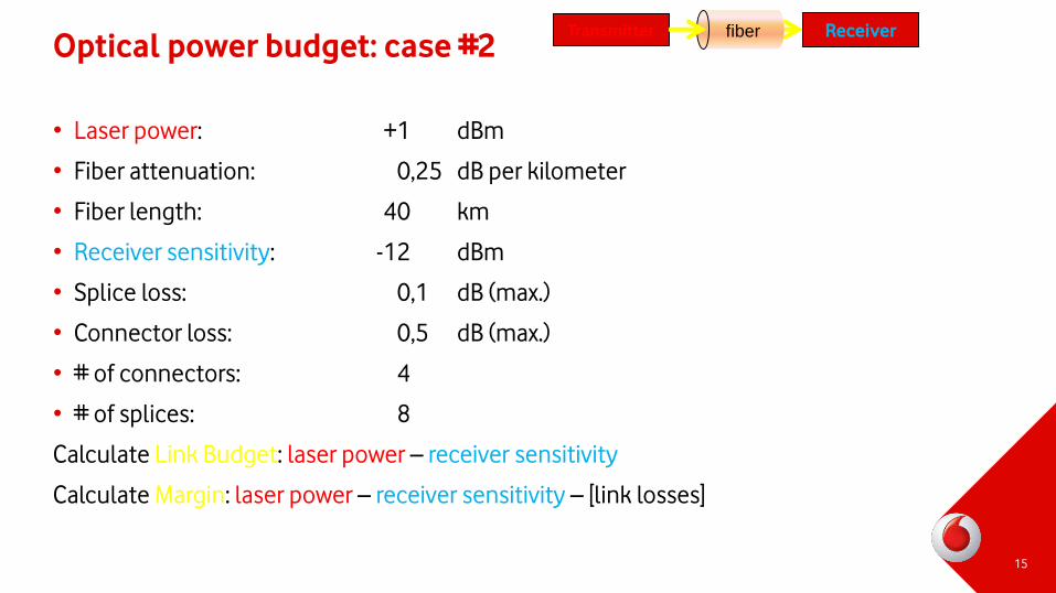
Optical power budget: case #2
• Laser power: +1 dBm
• Fiber attenuation: 0,25 dB per kilometer
• Fiber length: 40 km
• Receiver sensitivity: -12 dBm
• Splice loss: 0,1 dB (max.)
• Connector loss: 0,5 dB (max.)
• # of connectors: 4
• # of splices: 8
Calculate Link Budget: laser power – receiver sensitivity
Calculate Margin: laser power – receiver sensitivity – [link losses]
15
Transmitter Receiverfiber
Pros and cons of optical fiber
• Question for you all... Give me
– 3 advantages of optical fiber over metallic wiring
... and ...
– 3 disadvantages
16
Fiber networks
• Transport network layers
– Core (+ international) network
– Metro(politan) network
– Access network
• Access network for telecom/cableTV: partial fiber
– Telecom
– Optical fiber up to central office
– Copper connection into the home (xDSL)
– Cable TV
– Optical fiber up to street cabinet
– coax connection into the home
17
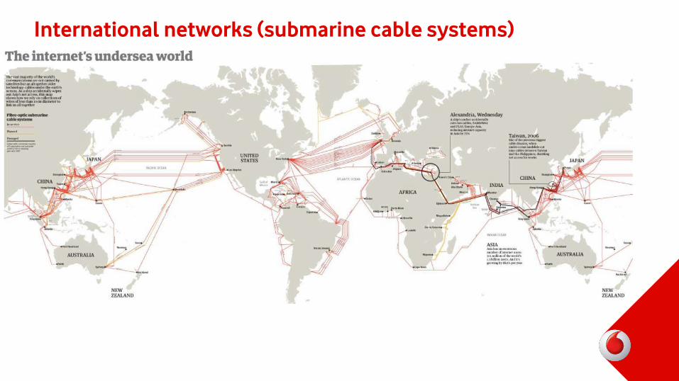
International networks (submarine cable systems)
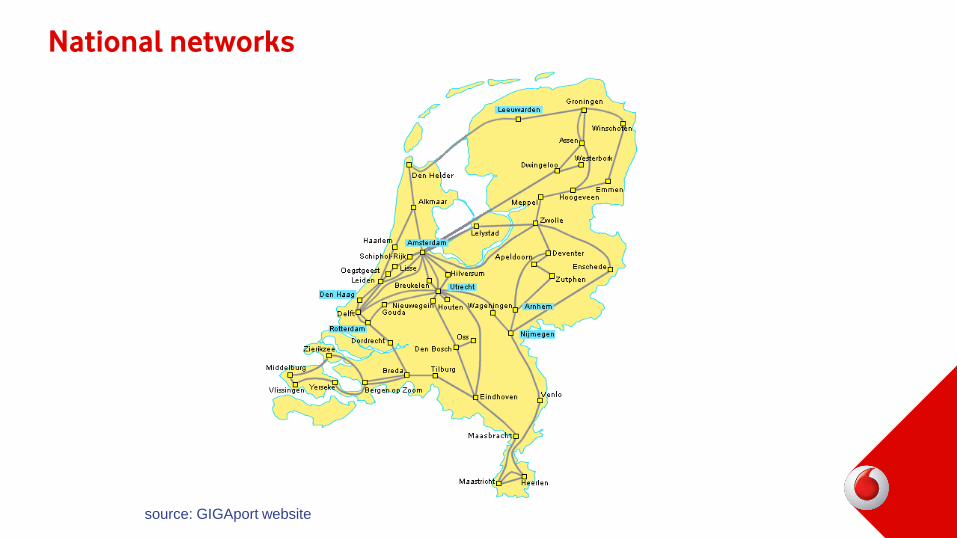
National networks
source: GIGAport website
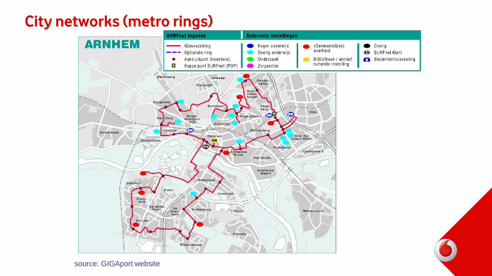
City networks (metro rings)
source: GIGAport website
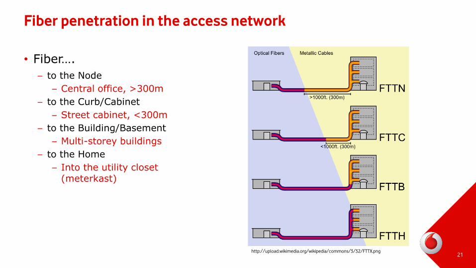
Fiber penetration in the access network
• Fiber….
– to the Node
– Central office, >300m
– to the Curb/Cabinet
– Street cabinet, <300m
– to the Building/Basement
– Multi-storey buildings
– to the Home
– Into the utility closet (meterkast)
21http://upload.wikimedia.org/wikipedia/commons/3/32/FTTX.png
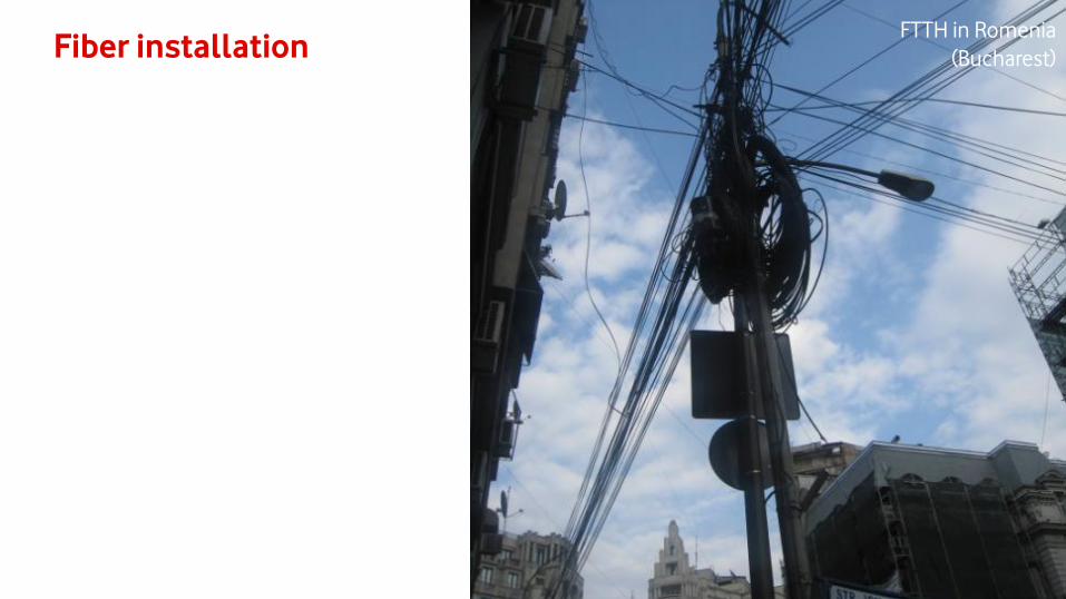
FTTH cabling concept
• Access network branches off multiple times between centraloffice and the home
• Installed: underground or above ground (!)
22
23
Fiber installationFTTH in Romenia
(Bucharest)
Underground installation
• Several underground deployment methods available
• 1: modular tubes; insert fiber as needed (blown fiber)
• 2: fiber inside rugged cable (buried fiber)
24
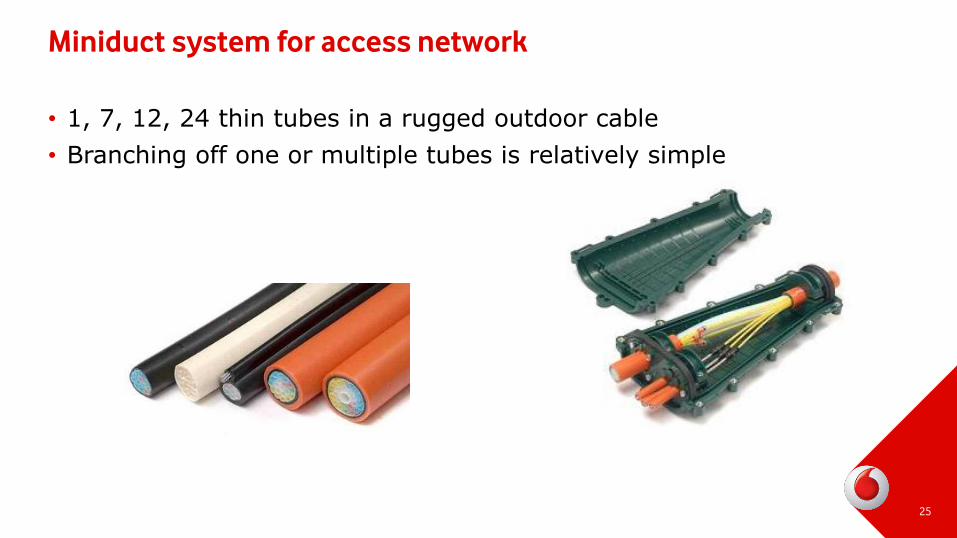
Miniduct system for access network
• 1, 7, 12, 24 thin tubes in a rugged outdoor cable
• Branching off one or multiple tubes is relatively simple
25
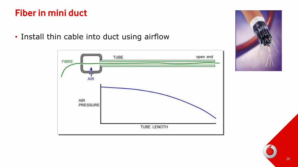
Fiber in mini duct
• Install thin cable into duct using airflow
26
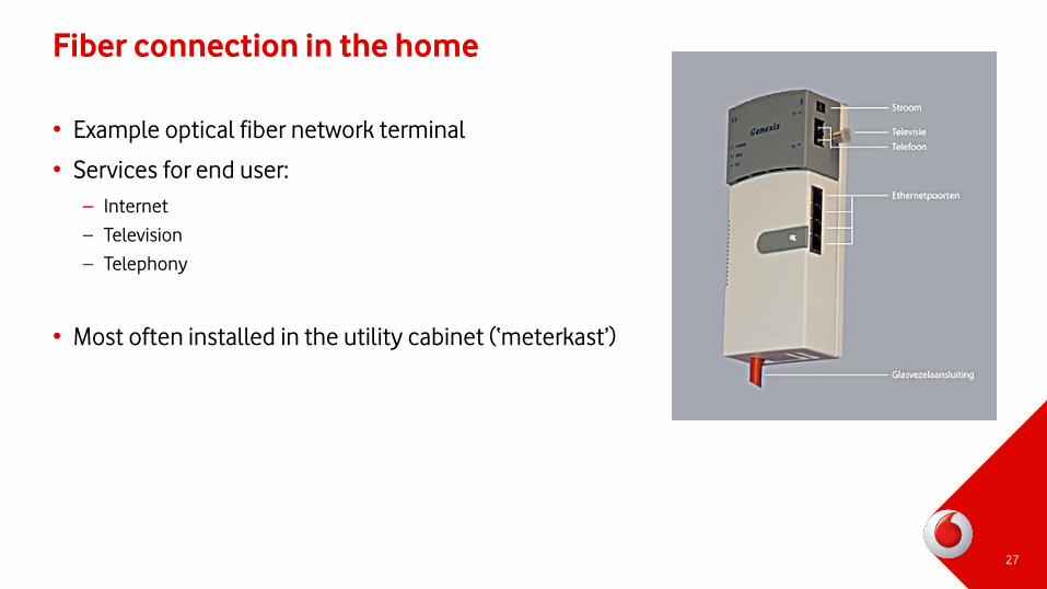
Fiber connection in the home
• Example optical fiber network terminal
• Services for end user:
– Internet
– Television
– Telephony
• Most often installed in the utility cabinet (‘meterkast’)
27
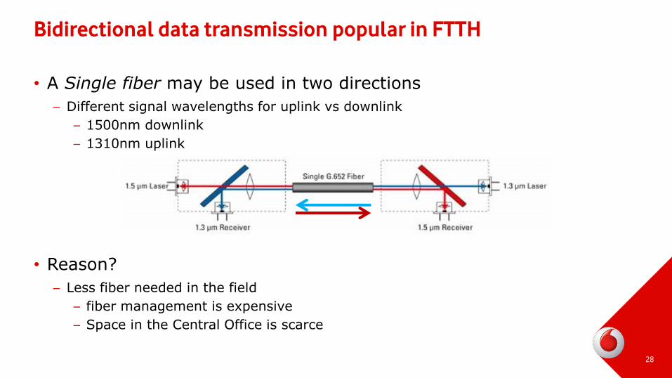
Bidirectional data transmission popular in FTTH
• A Single fiber may be used in two directions
– Different signal wavelengths for uplink vs downlink
– 1500nm downlink
– 1310nm uplink
• Reason?
– Less fiber needed in the field
– fiber management is expensive
– Space in the Central Office is scarce
28
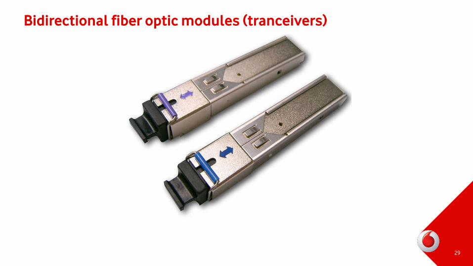
Bidirectional fiber optic modules (tranceivers)
29
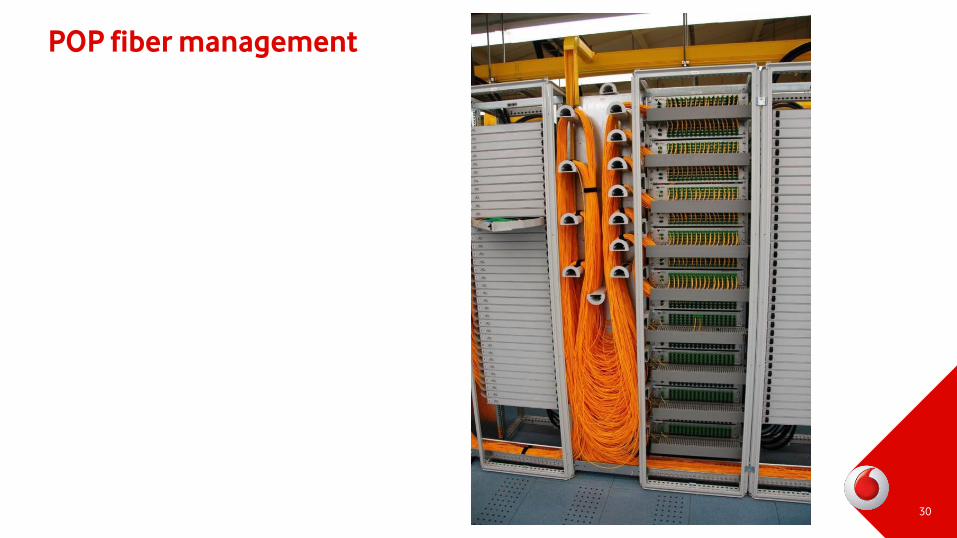
POP fiber management
30
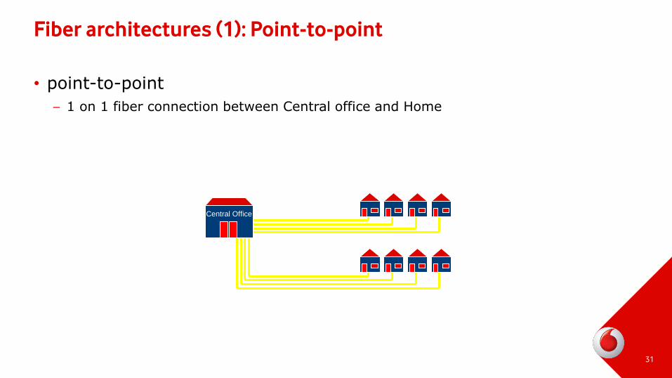
Fiber architectures (1): Point-to-point
• point-to-point
– 1 on 1 fiber connection between Central office and Home
31
Central Office
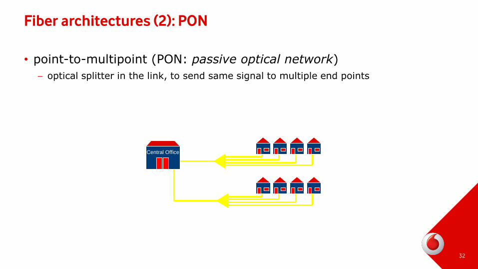
Fiber architectures (2): PON
• point-to-multipoint (PON: passive optical network)
– optical splitter in the link, to send same signal to multiple end points
32
Central Office
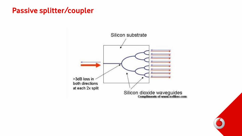
Passive splitter/coupler
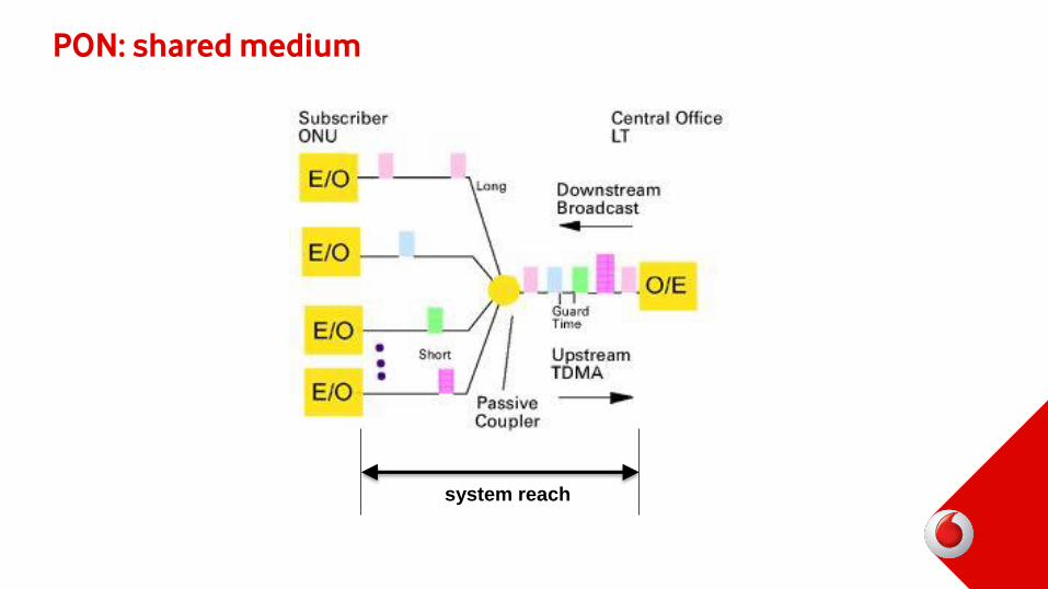
PON: shared medium
system reach
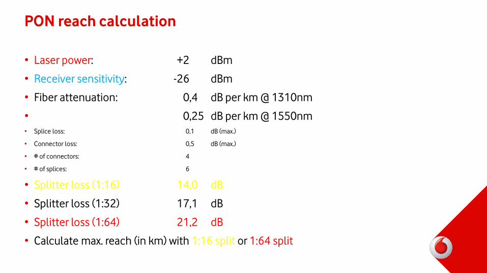
PON reach calculation
• Laser power: +2 dBm
• Receiver sensitivity: -26 dBm
• Fiber attenuation: 0,4 dB per km @ 1310nm
• 0,25 dB per km @ 1550nm
• Splice loss: 0,1 dB (max.)
• Connector loss: 0,5 dB (max.)
• # of connectors: 4
• # of splices: 6
• Splitter loss (1:16) 14,0 dB
• Splitter loss (1:32) 17,1 dB
• Splitter loss (1:64) 21,2 dB
• Calculate max. reach (in km) with 1:16 split or 1:64 split
PON versus Point-to-Point: who uses which?
• PON popular with telcos
– USA
– Japan
– Australia
– ‘closed business/network model’
• Point-to-point mostly popular in Europe
– Scandinavia
– Netherlands, France, etc
– ‘open network model’

![Optische netwerken - SNE/OS3 Homepage [OS3 Website] · · 2009-04-03Optische netwerken SNE opleiding - 19 maart 2009 Roeland Nuijts, ... optical fiber transmission systems were](https://img.dokumen.tips/doc/110x75/5af335217f8b9a8c3090c88e/optische-netwerken-sneos3-homepage-os3-website-netwerken-sne-opleiding-19.jpg)


![Jaap van Ginkel - SNE/OS3 Homepage [OS3 Website] · Jaap van Ginkel. Crypto Hash Function ... Cyclic Redundancy Check (CRC) ... Stream cipher based on one-time pad](https://img.dokumen.tips/doc/110x75/5b0c7d5f7f8b9abc0a8c47b4/jaap-van-ginkel-sneos3-homepage-os3-website-van-ginkel-crypto-hash-function.jpg)