Embed Size (px)
Citation preview

GOVERNMENT OF ORISSA
WORKS DEPARTMENT
ORISSA STATE ROAD PROJECT
FINAL DETAILED ENGINEERING REPORT FOR PHASE-I ROADS
DESIGN REPORT OF CULVERTS (BHAWANIPATNA TO KHARIAR)
������������������������������������������������������������������������
Engineers Group Ltd. Jaipur E-12, Moji Colony, Malviya Nagar , Jaipur, Raj. �+ 91-141-2520899, Telefax +91-141-2521348 E-mail : [email protected] URL : www.cegindia.com

Consulting Engineers Group Ltd., Jaipur Culvert Design Report
INDEX
Sl.No.
Title
Pages
1.
Introduction
1-6
2.
Design of Return Wall
i. 2.0m Height
ii. 3.0m Height
iii. 4.0m Height
iv. 5.0m Height
v. 6.0m Height
vi. 7.0m Height
1-5
1-5
1-5
1-5
1-5
1-5

CEG.Ltd., Jaipur Culvert Design Report
Consultancy Services for Feasibility Study and Detailed Project Preparation for Proposed Orissa State Road Project
INTRODUCTION

Consulting Engineers Group Ltd., Jaipur Culvert Design Report
INTRODUCTION
The culverts have been categorized on the basis of detailed inventory and condition survey, hydrological study, horizontal & vertical profile of highway. The following criterion has been taken while deciding the culverts :
i. The width of culvert shall be 12.0m ii. NP-3/NP-4 pipe culverts in good condition and hydrologically adequate shall be
retained iii. Slab culverts structurally in good condition and hydrologically adequate having width
less than 10.0m shall be widened as per approved alignment. iv. All arch type culverts shall be reconstructed. v. All new pipe culverts shall have minimum dia. of 1.0m and box culverts of minimum
span 2.0m and height 1.5m. vi. RR stone masonry culverts shall be reconstructed.
vii. Additional culverts as per site investigation has been identified and included in this report.
On the basis of above, all culverts lies in the following category :
i. Single Pipe Culverts of 1.0m dia
ii. Double Pipe Culverts of 1.0m dia iii. Extension of Pipe Culverts with existing pipe dia iv. Single Cell box Culverts upto span of 6.0m v. Widening of Slab Culverts
On the basis of above, all culverts in this stretch lies the following category
Summary of Proposed Culverts Type of Culvert Nos. Culverts Retained Culverts Widened Pipe extension 4 Slab widening Nil Culverts Replaced New Single Pipe 33 New Double Pipe 13 New Single Box of 1/22/0 11 New Single Box of 1/23/0 24 New Single Box of 1/33/0 4 New Single Box of 1/34/0 11 New Single Box of 1/43/0 2 New Single Box of 1/44/0 2 New Single Box of 1/45/0 4 New Single Box of 1/63/0 2 New Single Box of 1/64/0 1 Additional Culverts proposed

Consulting Engineers Group Ltd., Jaipur Culvert Design Report
Type of Culvert Nos. Single Pipe 1 Double Pipe 3 Single Cell Box of 1/22/0 3 Single Cell Box of 1/23/0 2 Total 120
The drawings of Pipe Culverts for height of fill from 0.6 to 4.0m has been taken from SP-13.For Box Culverts with different clear heights MOST Standard Drawings has been taken.
Bed levels, Formation levels, Super-elevation/Camber has been taken from highway plan & profile drawings and data has been analysed by using Microsoft Excel Sheet.
In Box Culverts, the retaining wall is kept along the road instead of splayed Wing Wall mentioned in MOST Drawings. These Walls has been designed by using Microsoft Excel Sheet for the height varying from 2.0 to 6.0m.
Reference codes: IRC – 6 – 2000 IRC – 21 – 2000 IRC – 78 – 2000
Proposed Culverts
S. No.
Location/ Chainage
Design Chainage
Existing Span
Arrangement
Type of Existing Culvert
Proposed Span
Arrangement
Type of Proposed Culvert
Remarks
1 3/450 3683 1 x 1.0 Slab 2 x 1.0 Pipe Reconstruction due to poor condition
2 4/100 4112 1 x 0.6 Pipe 1 x 1.0 Pipe
Replaced due to insufficient vent, to be used for Environmental purpose
3 5/450 5494 1 x 0.6 Pipe 1 x 1.0 Pipe Replaced due to insufficient vent
4 5/650 5691 1 x 1.2 Stone Slab 1/34/0 RCC Box Stone slab culvert, to be replaced
5 5/800 5800 - - 1/22/0 RCC Box Additional structure
6 6/550 6533 2 x 1.0 Pipe 1/34/0 RCC Box Replaced due to poor conditon
7 6/900 6935 1 x 2.4 Slab 1/45/0 RCC Box Replaced due to raise in road level
8 7/015 7030 1 x 0.6 Pipe 1 x 1.0 Pipe Replaced due to insufficient vent
9 7/800 7815 1 x 0.3 Stone Slab 1/22/0 RCC Box Stone slab culvert, to be replaced
10 9/450 9474 1 x 0.9 Slab 1/34/0 RCC Box Replaced due to poor condition
11 10/100 10109 1 x 0.6 Pipe 1/23/0 RCC Box Replaced due to insufficient vent
12 10/150 10147 2 x 1.0 Pipe 1/23/0 RCC Box Replaced due to poor condition

Consulting Engineers Group Ltd., Jaipur Culvert Design Report
S. No.
Location/ Chainage
Design Chainage
Existing Span
Arrangement
Type of Existing Culvert
Proposed Span
Arrangement
Type of Proposed Culvert
Remarks
13 10/700 10698 1 x 0.6 Pipe 1 x 1.0 Pipe Replaced due to insufficient vent
14 10/750 10744 1 x 1.9 Slab 1/34/0 RCC Box Reconstruction due to poor condition
15 11/650 11700 - - 1 x 1.0 Pipe Additional structure
16 12/600 12599 1 x 0.6 Pipe 1 x 1.0 Pipe Replaced due to insufficient vent
17 12/700 12687 1 x 1.8 Slab 1/23/0 RCC Box Replaced due to raise in road level
18 12/750 12746 1 x 0.6 Pipe 1 x 1.0 Pipe Replaced due to insufficient vent
19 12/800 12826 1 x 0.6 Pipe 1 x 1.0 Pipe Replaced due to insufficient vent
20 13/300 13341 1 x 1.0 Pipe - - To be widened
21 14/050 14055 1 x 0.9 Slab 1/22/0 RCC Box Replaced due to raise in road level
22 14/400 14372 2 x 0.9 Vented Causeway 1/23/0 RCC Box Vented causeway, to be
replaced
23 14/800 14799 3 x 1.0 Pipe 1/22/0 RCC Box Reconstruction due to poor condition
24 15/005 14990 1 x 0.6 Pipe 1 x 1.0 Pipe Replaced due to insufficient vent
25 15/250 15191 1 x 0.9 Vented Causeway 1 x 1.0 Pipe Vented causeway, to be
replaced
26 15/600 15574 1 x 0.6 Pipe 1/22/0 RCC Box Replaced due to insufficient vent
27 15/850 15830 2 x 0.9 Vented Causeway 1/45/0 RCC Box Vented causeway, to be
replaced
28 16/050 16002 1 x 0.6 Pipe 2 x 1.0 Pipe Replaced due to insufficient vent
29 17/500 17509 3 x 0.9 Vented Causeway 1/45/0 RCC Box Vented causeway, to be
replaced
30 18/100 18047 2 x 0.9 Vented Causeway 2 x 1.0 Pipe Vented causeway to be
replaced
31 18/850 18831 1 x 3.0 Arch 1/34/0 RCC Box Arch culvert to be replaced, to be used for Environmental purpose
32 19/700 19661 1 x 0.75 Pipe 1 x 1.0 Pipe Replaced due to insufficient vent
33 20/150 20112 5 x 1.0 Pipe 1/43/0 RCC Box Replaced due to insufficient vent
34 20/400 20337 5 x 1.0 Pipe 1/43/0 RCC Box Replaced due to insufficient vent
35 21/650 21607 2 x 0.9 Vented Causeway 2 x 1.0 Pipe Vented causeway, to be
replaced
36 22/150 22135 2 x 0.9 Vented Causeway 1/23/0 RCC Box
Vented causeway to be replaced, to be used for Environmental purpose
37 22/350 22380 2 x 0.9 Vented Causeway 2 x 1.0 Pipe Vented causeway to be
replaced
38 23/100 23061 2 x 0.9 Vented Causeway 1/23/0 RCC Box Vented causeway to be
replaced
39 23/250 23200 1 x 1.0 Pipe 1 x 1.0 Pipe Replaced due to raise in road level

Consulting Engineers Group Ltd., Jaipur Culvert Design Report
S. No.
Location/ Chainage
Design Chainage
Existing Span
Arrangement
Type of Existing Culvert
Proposed Span
Arrangement
Type of Proposed Culvert
Remarks
40 23/350 23321 2 x 0.9 Vented Causeway 1/34/0 RCC Box Vented causeway to be
replaced
41 23/650 23538 2 x 0.9 Vented Causeway 2 x 1.0 Pipe Vented causeway to be
replaced
42 24/100 24062 1 x 0.6 Pipe 1 x 1.0 Pipe Replaced due to insufficient vent
43 24/450 24402 3 x 1.2 Pipe - - To be widened
44 24/550 24513 3 x 0.9 Vented Causeway 2 x 1.0 Pipe Vented causeway to be
replaced
45 25/750 25723 2 x 0.9 Vented Causeway 2 x 1.0 Pipe Vented causeway to be
replaced
46 26/750 26695 2 x 0.9 Vented Causeway 2 x 1.0 Pipe Vented causeway to be
replaced
47 27/100 27045 1 x 0.6 Pipe 1 x 1.0 Pipe Reconstruction due to poor condition
48 27/250 27175 1 x 0.6 Pipe 1 x 1.0 Pipe Replaced due to insufficient vent
49 30/850 30830 1 x 1.5 Slab 1/23/0 RCC Box Reconstruction due to poor condition
50 31/250 31300 1 x 1.5 Slab 1/23/0 RCC Box Reconstruction due to poor condition
51 32/050 32044 1 x 1.5 Slab 1/23/0 RCC Box Replaced due to raise in road level
52 33/200 33238 1 x 3.0 Slab 1/23/0 RCC Box Replaced due to raise in road level
53 33/800 33800 - - 1/23/0 RCC Box Additional structure
54 34/700 34732 1 x 1.5 Slab 2 x 1.0 Pipe Replaced due to Submergence
55 35/985 36050 - - 1/22/0 RCC Box Additional structure
56 36/900 36961 1 x 1.5 Slab 1/33/0 RCC Box Replaced due to Submergence
57 37/100 37214 1 x 1.5 Slab 1/34/0 RCC Box Replaced due to Submergence
58 37/400 37563 1 x 1.5 Slab 1/23/0 RCC Box Replaced due to Submergence
59 38/400 38383 1 x 1.5 Slab 1/23/0 RCC Box Replaced due to Submergence
60 39/100 39150 - - 2 x 1.0 Pipe Additional structure
61 40/100 40089 1 x 1.5 Slab 1/23/0 RCC Box Replaced due to Submergence
62 40/950 41037 1 x 1.5 Slab 1/22/0 RCC Box Replaced due to raise in road level
63 41/300 41409 1 x 1.5 Slab 1/23/0 RCC Box Reconstruction due to poor condition
64 41/700 41789 1 x 1.5 Slab 1/45/0 RCC Box Replaced due to raise in road level
65 42/200 42320 1 x 1.5 Slab 1/34/0 RCC Box Replaced due to raise in road level
66 42/550 42635 1 x 0.45 Pipe 1 x 1.0 Pipe Reconstruction due to poor condition
67 43/100 43159 1 x 3.0 Slab 1/33/0 RCC Box Reconstruction due to poor condition

Consulting Engineers Group Ltd., Jaipur Culvert Design Report
S. No.
Location/ Chainage
Design Chainage
Existing Span
Arrangement
Type of Existing Culvert
Proposed Span
Arrangement
Type of Proposed Culvert
Remarks
68 44/150 44261 1 x 1.5 Slab 1/22/0 RCC Box Replaced due to raise in road level
69 44/850 44954 1 x 3.0 Slab 1/34/0 RCC Box Reconstruction due to poor condition
70 45/150 45296 1 x 0.6 Pipe 1 x 1.0 Pipe Replaced due to insufficient vent
71 45/600 45711 1 x 0.6 Pipe 1/23/0 RCC Box Reconstruction due to poor condition
72 45/850 46047 1 x 4.5 Slab 1/63/0 RCC Box Replaced due to raise in road level
73 46/200 46325 - - 2 x 1.0 Pipe Additional structure
74 46/350 46514 1 x 1.5 Slab 1/22/0 RCC Box Replaced due to raise in road level
75 47/050 47165 1 x 1.5 Slab 1/22/0 RCC Box Replaced due to raise in road level
76 47/200 47322 1 x 1.5 Slab 1 x 1.0 Pipe Reconstruction due to poor condition
77 49/600 49726 1 x 1.5 Slab 1/23/0 RCC Box Replaced due to raise in road level
78 50/150 50287 1 x 1.5 Slab 1/44/0 RCC Box Replaced due to raise in road level
79 50/300 50499 1 x 1.5 Slab 1/23/0 RCC Box Reconstruction due to poor condition
80 51/025 51174 1 x 0.6 Pipe 1 x 1.0 Pipe Replaced due to insufficient vent
81 51/250 51409 1 x 0.9 Pipe 2 x 1.0 Pipe Replaced due to insufficient vent
82 51/400 51580 1 x 0.9 Pipe 2 x 1.0 Pipe Replaced due to insufficient vent
83 51/600 51760 2 x 0.9 Pipe 1/34/0 RCC Box Replaced due to raise in road level
84 51/900 52068 1 x 0.6 Pipe 1 x 1.0 Pipe Reconstruction due to poor condition
85 52/100 52296 1 x 0.6 Pipe 2 x 1.0 Pipe Reconstruction due to poor condition
86 52/250 52424 1 x 0.9 Pipe 1 x 1.0 Pipe Reconstruction due to poor condition
87 52/700 52844 4 x 0.9 Pipe - - To be widened
88 53/500 53679 1 x 0.9 Pipe 1 x 1.0 Pipe Replaced due to insufficient vent
89 53/950 54148 1 x 1.4 Slab 1/23/0 RCC Box Replaced due to raise in road level
90 54/350 54606 1 x 1.3 Slab 1/44/0 RCC Box
Replaced due to raise in road level, to be used for Environmental purpose
91 55/250 55420 1 x 1.5 Slab 1 x 1.0 Pipe Replaced due to Submergence
92 56/100 56270 1 x 5.0 Slab 1/64/0 RCC Box Reconstruction due to poor condition
93 56/200 56390 - - 1/22/0 RCC Box Additional structure
94 56/400 56587 1 x 0.9 Pipe - - To be widened

Consulting Engineers Group Ltd., Jaipur Culvert Design Report
S. No.
Location/ Chainage
Design Chainage
Existing Span
Arrangement
Type of Existing Culvert
Proposed Span
Arrangement
Type of Proposed Culvert
Remarks
95 56/950 57150 - - 2 x 1.0 Pipe Additional structure
96 57/150 57321 1 x 0.9 Pipe 1 x 1.0 Pipe Reconstruction due to poor condition
97 57/500 57360 1 x 0.6 Pipe 1 x 1.0 Pipe Replaced due to insufficient vent
98 57/900 57664 1 x 0.45 Skew Pipe 1 x 1.0 Pipe Reconstruction due to poor condition
99 59/850 59625 1 x 0.45 Pipe 1 x 1.0 Pipe Reconstruction due to poor condition
100 60/100 59915 1 x 3.0 Slab 1/33/0 RCC Box Replaced due to raise in road level
101 60/750 60567 1 x 1.5 Slab 1/34/0 RCC Box Replaced due to raise in road level
102 61/550 61373 1 x 1.5 Slab 1/23/0 RCC Box Reconstruction due to poor condition
103 62/250 62100 1 x 3.0 Slab 1/33/0 RCC Box Reconstruction due to poor condition
104 62/900 62962 1 x 0.6 Pipe 1 x 1.0 Pipe Replaced due to insufficient vent
105 63/200 63300 1 x 1.5 Slab 1/23/0 RCC Box Replaced due to raise in road level
106 63/550 63298 1 x 6.2 Slab 1/63/0 RCC Box Reconstruction due to poor condition
107 63/900 63700 1 x 1.5 Slab 1 x 1.0 Pipe Replaced due to raise in road level
108 64/600 64622 1 x 0.6 Pipe 1 x 1.0 Pipe Replaced due to insufficient vent
109 64/825 64891 1 x 0.6 Pipe 1 x 1.0 Pipe
Replaced due to insufficient vent, to be used for Environmental purpose
110 65/100 65122 1 x 0.6 Pipe 1 x 1.0 Pipe Replaced due to insufficient vent
111 65/350 65430 1 x 1.5 Slab 1 x 1.0 Pipe Replaced due to raise in road level
112 65/675 65624 1 x 1.5 Slab 1/23/0 RCC Box Reconstruction due to poor condition
113 65/900 66027 1 x 1.5 Slab 1/22/0 RCC Box Reconstruction due to poor condition
114 66/200 66161 1 x 0.9 Pipe 1/23/0 RCC Box Replaced due to insufficient vent
115 66/430 66500 - - 1/23/0 RCC Box Additional structure
116 67/300 67100 1 x 0.6 Pipe 1/22/0 RCC Box Replaced due to raise in road level
117 67/550 67325 1 x 0.9 Pipe 1 x 1.0 Pipe Replaced due to insufficient vent
118 67/850 67620 1 x 0.9 Pipe 1/23/0 RCC Box
Replaced due to raise in road level, to be used for Environmental purpose
119 68/200 68010 1 x 0.6 Pipe 1/23/0 RCC Box Replaced due to insufficient vent
120 68/700 68445 1 x 1.5 Slab 1/22/0 RCC Box Replaced due to raise in road level

CEG.Ltd., Jaipur Culvert Design Report
Consultancy Services for Feasibility Study and Detailed Project Preparation for Proposed Orissa State Road Project
DESIGN OF RETURN WALL

Consulting Engineers Group Ltd., Jaipur_________________________________________________________________________________
Culvert Design Report_________________________________________________________
Top of Earth fill
Top level of wall
0.30
1.700
Earth Fill
2.000
Ground level
Heel Toe0.300 0.300 0.300
1.300 0.300 0.4002.000
Stra
ight
por
tion
of s
tem
=
9
13
2
3
4 6
5711 14
1
8
10
12
9
13
2
3
4 6
5711 14
1
8
10
12

Consulting Engineers Group Ltd., Jaipur_________________________________________________________________________________
Culvert Design Report_________________________________________________________
DESIGN OF RETAINING WALL FOR 2.000 m HEIGHTDESIGN DATA:Top level of retaining wall = 2.000 mGround level = 1.000 mFounding Level = 0.000 m
Total Height from top of wall to founding level = 2.000 m
Density of earth = 1.8 t/m3
Density of concrete = 2.4 t/m3
Clear cover to Reinforcement = 0.05 mClear cover to Reinforcement for foundations = 0.075 mGrade of concrete = 20Allowable stress in steel = 20380Safe bearing capacity = 20 t/m2
Safety factor against overturning = 2.0 Safety factor against sliding = 1.5Depth of L.L.Surcharge = 1.2 mL.L.Surcharge on wall = 0 t/m^2ActiveEarthPressureFor Grade of concrete = M 20 & HYSD reinf. with Fe 415Lever arm factor j = 0.916Moment of resistance factor Q = 78.54
DIMENSIONS :Length of Base of Retaining wall = 2.000 mSection modulus = 0.667 m3
Length of Toe = 0.400 mLength of Heel = 1.300 mThickness of Stem at base = 0.300 mThickness of straight portion of stem = 0.300 mHt. of straight portion of stem = 1.700 mMinimum thickness of Toe slab = 0.300 mThickness of Toe slab at junction with stem = 0.300 mMinimum thickness of heel slab = 0.300 mThickness of heel slab at junction with stem = 0.300 mAngle of inclined stem with vertical = 0.000Ht.of inclined potion of stem to base of footing = 0.300 mHt.of inclined potion of stem to top of footing = 0.000 mCalculation of Earth pressure coefficients =Angle of internal friction of soil φ = 30 deg = 0.524 radAngle of wall friction δ = 20 deg = 0.349 radAngle of incli . of soil at back i = 0 deg = 0.000 radAngle of incli . of stem at back α = 90 deg = 1.571 radCoefficient of active earth pressure ka = 0.297
Coefficient of horz.active earth pressure Kah = 0.279

Consulting Engineers Group Ltd., Jaipur_________________________________________________________________________________
Culvert Design Report_________________________________________________________
Calculation of Forces & moments due to Vertical Forces
S.No. Description Area Factor width Depth Density WeightC.G. from Toe
Moment about
toe1 1.0 0.300 1.7 2.4 1.224 0.550 0.6732 0.5 0.000 0 2.4 0.000 0.700 0.0003 0.5 1.300 0 2.4 0.000 1.133 0.0004 1.0 1.300 0.3 2.4 0.936 1.350 1.2645 0.5 0.400 0 2.4 0.000 0.267 0.0006 1.0 0.400 0.3 2.4 0.288 0.200 0.0587 Wt.of intmdt.portion 1.0 0.300 0.3 2.4 0.216 0.550 0.1198 1.0 1.300 1.7 1.8 3.978 1.35 5.3709 0.5 0.000 0 1.8 0.000 0.700 0.00010 1.0 1.300 0 1.8 0.000 1.350 0.00011 0.5 1.300 0 1.8 0.000 1.567 0.00012 0.0 1.300 0.65 1.8 0.000 1.567 0.00013 0.0 0.4 0.7 1.8 0.000 0.200 0.00014 0.0 0.4 0 1.8 0.000 0.133 0.00015 L.L.Surcharge 0.0 1.3 1.2 1.8 0.000 1.350 0.000
Total forces = 6.642 7.48Total Vertical load = 6.64 Total Restoring moment = 7.48
Horz. components of Earth Pressure
S.No.Area
factorPressure
kahγh HeightHorz. Force
C.G. from Toe
Moment about
toe1 0.5 1.006 2 1.006 0.840 0.842 1 0.603 2 1.207 1.000 1.21
Total forces = 2.213 2.05
2.05 tm Total vertical load V = 6.642 t7.48 tm Total Horz. Force = 2.213 t
3.65 OK > 2Check for sliding : Coefficient of base friction = 0.500Total vertical force = 6.642 tResisting force = 3.32 tF.O.S 1.501 OK > 1.5
1.127 m0.127 m
Moment about c/l raft = 0.842 t-mNet moment about base Mn = 1.210 t-mCalculation of Base Pressure Base pressure due to vertical load V/A = 3.32 Pressure at toe = 5.14 t/m2
Base pressure due to moment Mn/Z = 1.815 Pressure at heel= 1.51 t/m2
Wt. of soil above heel slab
Active Earth Pressure
Horz. Press due to
Wt of stem
Wt of heel slab
Wt of toe slab
Total overturning moment Mo =
Eccentricity of loads w.r.t. c/l raft =
Wt. of soil above toe slab
Factor of safety against overturning Mr/Mo =
C.G. of loads from toe = Mr/V =
Total restoring moment Mr =
L.L.Surcharge

Consulting Engineers Group Ltd., Jaipur_________________________________________________________________________________
Culvert Design Report_________________________________________________________
CALCULATION OF DESIGN PRESSURES1-1 2-2 3-3 4-4 5-5
5.136 4.410 3.866 1.506 4.7420.720 0.720 3.780 3.780 0.7204.416 3.690 0.086 -2.274 4.022
** Positive net pressure means upward pressure & negative net pressure means downward pressure
4 3 2 5 1 d
Heel Toe
1.300 0.400
Point of zero press. from stem = 0.00 mPoint of zero press. from end of heel = 1.30 m
2.000 4 3 2 5 1DESIGN OF TOE SLAB
Bending Moment at face of stem = 0.33 t-mEffective depth required = 0.065 m
= 0.217 > reqd 0.065Area of Reinforcement reqd.at bottom = 0.82 cm2 HENCE SAFE
= 0.77 tBending moment at sec 5-5 = 0.07 t-mNet shear force at sec 5-5=S-Ms*tanβ/d1 = 0.77 t
Depth of slab at section 5-5 = 0.300Effective depth d1
=0.215 m
Nominal Shear stress = 2.57 t/m2
Permissible shear strsss is calculated as per cl.304.7.1.3 of IRC:21-2000100As/bd = 0.038 %Therefore Permissible shear strsss = 18.36 t/m2 HENCE SAFEDESIGN OF HEEL SLAB
1.26 t-mEffective depth required = 0.127 m
0.215 mReinforcement reqd.at top = 3.13 cm2
1.42 tBending moment at face Ms = 1.26 t-mNet shear force =S-Ms*tanβ/d1 = 1.42 tNominal Shear stress = 6.62 t/m2
Permissible shear strsss is calculated as per cl.304.7.1.3 of IRC:21-2000100As/bd = 0.146 %Therefore Permissible shear stress = 18.36 t/m2 HENCE SAFE
Reinforcement calculation
Effective depth of slab at face of stem =
Shear force at face of stem S =
Effective depth provided at face of stem
Shear force at distance d from stem Shear check:
Shear check:
Bending Moment at face of stem =
SectionUpward pressureDownward PressureNet pressure

Consulting Engineers Group Ltd., Jaipur_________________________________________________________________________________
Culvert Design Report_________________________________________________________
DESIGN OF STEM BASESection A
Height of Base of stem from top of earth fill = 1.7 mHeight of Base of stem below straight portion = 5.6E-17 m
S.No.Area
factorPressure ka.g.h Height
Horz. Force
C.G. from base
Moment about base
1 0.5 0.855 1.7 0.727 0.714 0.52
2 1 0.603 1.7 1.026 0.850 0.87
Total = 1.75 1.39Total Horizontal Force 1.75 tTotal Moment about base 1.39 tmDesign bending moment 1.39 t-mEffective depth required 0.133 mThickness of stem at base 0.300 mEffective depth provided 0.238 > 0.133 HENCE SAFEArea of steel reqd. 3.14 cm2
Shear check: Shear force at base of stem 1.75 tBending moment at base 1.39 t-mNet shear force 1.75 tNominal Shear stress 7.38 t/m2
Permissible shear stress is calculated as per cl.304.7.1.3 of IRC:21-2000= 0.15 %
ActiveEarthPressure 18.40 t/m2 HENCE SAFE
L.L.Surcharge
100As/bd
Horz. Press due to
ActiveEarthPressure

Consulting Engineers Group Ltd., Jaipur______________________________________________________________________
Culvert Design Report__________________________________________________________________
Top of Earth fill
Top level of wall
0.30
2.400
Earth Fill
3.000
Ground level
Heel 0.300 Toe0.300 0.300
1.750 0.300 0.6002.650
Str
aigh
t por
tion
of s
tem
=
9
13
2
3
4 6
5711 14
1
8
10
12

Consulting Engineers Group Ltd., Jaipur______________________________________________________________________
Culvert Design Report__________________________________________________________________
DESIGN OF RETAINING WALL FOR 3.000 m HEIGHTDESIGN DATA:Top level of retaining wall = 3.000 mGround level = 1.000 mFounding Level = 0.000 m
Total Height from top of wall to founding level = 3.000 m
Density of earth = 1.8 t/m3
Density of concrete = 2.4 t/m3
Clear cover to Reinforcement = 0.05 mClear cover to Reinforcement for foundations = 0.075 mGrade of concrete = 25Allowable stress in steel = 20380Safe bearing capacity = 20 t/m2
Safety factor against overturning = 2.0
Safety factor against sliding = 1.5Depth of L.L.Surcharge = 1.2 mL.L.Surcharge on wall = 0 t/m^2DESIGN CONSTANTS:For Grade of concrete = M 20 & HYSD reinf. with Fe 415Lever arm factor j = 0.902Moment of resistance factor Q = 111.996DIMENSIONS :Length of Base of Retaining wall = 2.650 mSection modulus = 1.170 m3
Length of Toe = 0.600 mLength of Heel = 1.750 mThickness of Stem at base = 0.300 mThickness of straight portion of stem = 0.300 mHt. of straight portion of stem = 2.400 mMinimum thickness of Toe slab = 0.300 mThickness of Toe slab at junction with stem = 0.300 mMinimum thickness of heel slab = 0.300 mThickness of heel slab at junction with stem = 0.300 mAngle of inclined stem with vertical = 0.000Ht.of inclined potion of stem to base of footing = 0.600 mHt.of inclined potion of stem to top of footing = 0.300 mCalculation of Earth pressure coefficients =Angle of internal friction of soil φ = 30 deg = 0.5236 radAngle of wall friction δ = 20 deg = 0.3491 rad
Angle of incli . of soil at back i = 0 deg = 0.0000 radAngle of incli . of stem at back α = 90 deg = 1.570796 radCoefficient of active earth pressure ka = 0.297
Coefficient of horz.active earth pressure Kah = 0.279

Consulting Engineers Group Ltd., Jaipur______________________________________________________________________
Culvert Design Report__________________________________________________________________
Calculation of Forces & moments due to Vertical Forces
S.No. DescriptionArea
Factorwidth Depth Density Weight
C.G. from Toe
Moment about
toe1 1.0 0.300 2.7 2.4 1.944 0.750 1.4582 0.5 0.000 0.3 2.4 0.000 0.900 0.0003 0.5 1.750 0 2.4 0.000 1.483 0.0004 1.0 1.750 0.3 2.4 1.260 1.775 2.2375 0.5 0.600 0 2.4 0.000 0.400 0.0006 1.0 0.600 0.3 2.4 0.432 0.300 0.1307 Wt.of intmdt.portion 1.0 0.300 0.3 2.4 0.216 0.750 0.1628 1.0 1.750 2.4 1.8 7.560 1.775 13.4199 0.5 0.000 0.3 1.8 0.000 0.900 0.00010 1.0 1.750 0.3 1.8 0.945 1.775 1.67711 0.5 1.750 0 1.8 0.000 2.067 0.00012 0.0 1.750 0.875 1.8 0.000 2.067 0.00013 0.0 0.6 0.7 1.8 0.000 0.300 0.00014 0.0 0.6 0 1.8 0.000 0.200 0.00015 L.L.Surcharge 0.0 1.75 1.2 1.8 0.000 1.775 0.000
Total forces = 12.357 19.08Total Vertical load = 12.36 Total Restoring moment = 19.08
Horz. components of Earth Pressure
S.No. Horz. Press due to Area
factorPressure
kahγh Height Horz. ForceC.G. from Toe
Moment about
toe1 0.5 1.509 3 2.263 1.260 2.852 1 0.603 3 1.810 1.500 2.72
Total forces = 4.073 5.57
5.57 tm Total vertical load V = 12.357 t19.08 tm Total Horz. Force = 4.073 t
3.43 OK > 2Check for sliding : Coefficient of base friction = 0.500Total vertical force = 12.357 tResisting force = 6.18 tF.O.S 1.52 OK > 1.5
1.544 m0.219 m
Moment about c/l raft = 2.709 t-mNet moment about base Mn = 2.858 t-mCalculation of Base Pressure Base pressure due to vertical load V/A = 4.66 Pressure at toe = 7.10 t/m2
Base pressure due to moment Mn/Z = 2.441 Pressure at heel= 2.22 t/m2
Total overturning moment Mo =
Eccentricity of loads w.r.t. c/l raft =
Wt. of soil above toe slab
Factor of safety against overturning Mr/Mo =
C.G. of loads from toe = Mr/V =
Total restoring moment Mr =
L.L.Surcharge
Wt. of soil above heel slab
Active Earth Pressure
Wt of stem
Wt of heel slab
Wt of toe slab

Consulting Engineers Group Ltd., Jaipur______________________________________________________________________
Culvert Design Report__________________________________________________________________
CALCULATION OF DESIGN PRESSURES1-1 2-2 3-3 4-4 5-5
7.104 5.999 5.446 2.222 6.7050.720 0.720 5.580 5.580 0.7206.384 5.279 -0.134 -3.358 5.985
** Positive net pressure means upward pressure & negative net pressure means downward pressure
4 3 2 5 1 d
Heel Toe
1.750 0.600
2.650 4 3 2 5 1DESIGN OF TOE SLAB
Bending Moment at face of stem = 1.08 t-mEffective depth required = 0.098 m
= 0.217 > reqd 0.098Area of Reinforcement reqd.at bottom = 2.71 cm2 HENCE SAFE
= 2.37 tBending moment at sec 5-5 = 0.46 t-mNet shear force at sec 5-5=S-Ms*tanβ/d1 = 2.37 tDepth of slab at section 5-5 = 0.300 Effective depth d1 = 0.215 mNominal Shear stress = 7.90 t/m2
Permissible shear strsss is calculated as per cl.304.7.1.3 of IRC:21-2000100As/bd = 0.126 %Therefore Permissible shear strsss = 18.36 t/m2 HENCE SAFEDESIGN OF HEEL SLAB
3.50 t-mEffective depth required = 0.177 m
0.215 mReinforcement reqd.at top = 8.85 cm2
3.06 tBending moment at face Ms = 3.50 t-mNet shear force =S-Ms*tanβ/d1 = 3.06 tNominal Shear stress = 14.21 t/m2
Permissible shear strsss is calculated as per cl.304.7.1.3 of IRC:21-2000100As/bd = 0.412 %Therefore Permissible shear strsss = 27.71 t/m2 HENCE SAFE
SectionUpward pressureDownward PressureNet pressure
Reinforcement calculation
Effective depth of slab at face of stem =
Shear force at face of stem S =
Effective depth provided at face of stem
Shear force at distance d from stem Shear check:
Shear check:
Bending Moment at face of stem =

Consulting Engineers Group Ltd., Jaipur______________________________________________________________________
Culvert Design Report__________________________________________________________________
DESIGN OF STEM BASESection A
Height of Base of stem from top of earth fill = 2.7 mHeight of Base of stem below straight portion = 0.3 m
S.No.Area
factorPressure
ka.g.h HeightHorz. Force
C.G. from base
Moment about base
1 0.5 1.358 2.7 1.833 1.134 2.08
2 1 0.603 2.7 1.629 1.350 2.20
Total = 3.46 4.28Total Horizontal Force 3.46 tTotal Moment about base 4.28 tmDesign bending moment 4.28 t-mEffective depth required 0.195 mThickness of stem at base 0.300 mEffective depth provided 0.238 > 0.195 HENCE SAFEArea of steel reqd. 9.80 cm2
Shear force at base of stem 3.46 tBending moment at base 4.28 t-mNet shear force 3.46 tNominal Shear stress 14.58 t/m2
Permissible shear strsss is calculated as per cl.304.7.1.3 of IRC:21-2000= 0.41 %
Therefore Permissible shear strsss 27.75 t/m2 HENCE SAFE
Horz. Press due to
Active Earth Pressure
Shear check:
100As/bd
L.L.Surcharge

Consulting Engineers Group Ltd., Jaipur___________________________________________________________________________
Culvert Design Report____________________________________________________
Top of Earth fill
Top level of wall
0.30
2.400
Earth Fill
4.000
Ground level
Heel 0.450 Toe0.300 0.300
2.040 0.410 0.7003.150
Str
aigh
t por
tion
of s
tem
=
9
13
2
3
4 6
5711 14
1
8
10
12

Consulting Engineers Group Ltd., Jaipur___________________________________________________________________________
Culvert Design Report____________________________________________________
DESIGN OF RETAINING WALL FOR 4.000 m HEIGHTDESIGN DATA:Top level of retaining wall = 4.000 mGround level = 1.500 mFounding Level = 0.000 m
Total Height from top of wall to founding level = 4.000 m
Density of earth = 1.8 t/m3
Density of concrete = 2.4 t/m3
Clear cover to Reinforcement = 0.05 mClear cover to Reinforcement for foundations = 0.075 mGrade of concrete = 20Allowable stress in steel = 20380Safe bearing capacity = 20 t/m2
Safety factor against overturning = 2.0
Safety factor against sliding = 1.5Depth of L.L.Surcharge = 1.2 mL.L.Surcharge on wall = 0 t/m^2DESIGN CONSTANTS:For Grade of concrete = M 20 & HYSD reinf. with Fe 415Lever arm factor j = 0.916Moment of resistance factor Q = 78.54DIMENSIONS :Length of Base of Retaining wall = 3.150 mSection modulus = 1.654 m3
Length of Toe = 0.700 mLength of Heel = 2.040 mThickness of Stem at base = 0.410 mThickness of straight portion of stem = 0.300 mHt. of straight portion of stem = 2.400 mMinimum thickness of Toe slab = 0.300 mThickness of Toe slab at junction with stem = 0.450 mMinimum thickness of heel slab = 0.300 mThickness of heel slab at junction with stem = 0.450 mAngle of inclined stem with vertical = 0.096Ht.of inclined potion of stem to base of footing = 1.600 mHt.of inclined potion of stem to top of footing = 1.150 mCalculation of Earth pressure coefficients =Angle of internal friction of soil φ = 30 deg = 0.524 radAngle of wall friction δ = 20 deg = 0.349 rad
Angle of incli . of soil at back i = 0 deg = 0.000 radAngle of incli . of stem at back α = 90 deg = 1.57080 radCoefficient of active earth pressure ka = 0.297
Coefficient of horz.active earth pressure Kah = 0.279

Consulting Engineers Group Ltd., Jaipur___________________________________________________________________________
Culvert Design Report____________________________________________________
Calculation of Forces & moments due to Vertical Forces
S.No.
DescriptionArea
Factorwidth Depth Density Weight
C.G. from Toe
Moment about
toe1 1.0 0.300 3.55 2.4 2.556 0.850 2.1732 0.5 0.110 1.15 2.4 0.152 1.037 0.1573 0.5 2.040 0.15 2.4 0.367 1.790 0.6574 1.0 2.040 0.3 2.4 1.469 2.130 3.1295 0.5 0.700 0.15 2.4 0.126 0.467 0.0596 1.0 0.700 0.3 2.4 0.504 0.350 0.1767 Wt.of intmdt.portion 1.0 0.410 0.45 2.4 0.443 0.905 0.4018 1.0 2.150 2.4 1.8 9.288 2.075 19.2739 0.5 0.110 1.15 1.8 0.114 1.073 0.12210 1.0 2.040 1.15 1.8 4.223 2.130 8.99511 0.5 2.040 0.15 1.8 0.275 2.470 0.68012 0.0 2.150 1.075 1.8 0.000 2.434 0.00013 0.0 0.7 1.1 1.8 0.000 0.350 0.00014 0.0 0.7 0.15 1.8 0.000 0.233 0.00015 L.L.Surcharge 0.0 2.15 1.2 1.8 0.000 2.075 0.000
Total forces = 19.517 35.82Total Vertical load = 19.52 Total Restoring moment = 35.82
Horz. components of Earth Pressure
S.No.
Horz. Press due to Area
factorPressure
kahγh Height Horz. ForceC.G. from Toe
Moment about
toe1 0.5 2.012 4 4.023 1.680 6.762 1 0.603 4 2.414 2.000 4.83
Total forces = 6.437 11.59
11.59 tm Total vertical load V = 19.517 t35.82 tm Total Horz. Force = 6.437 t
3.09 OK > 2Check for sliding : Coefficient of base friction = 0.500Total vertical force = 19.517 tResisting force = 9.76 tF.O.S 1.52 OK > 1.5
1.835 m0.260 m
Moment about c/l raft = 5.083 t-mNet moment about base Mn = 6.504 t-mCalculation of Base Pressure Base pressure due to vertical load V/A = 6.20 Pressure at toe = 10.13 t/m2
Base pressure due to moment Mn/Z = 3.933 Pressure at heel= 2.26 t/m2
Wt. of soil above heel slab
Active Earth Pressure
Wt of stem
Wt of heel slab
Wt of toe slab
Total overturning moment Mo =
Eccentricity of loads w.r.t. c/l raft =
Wt. of soil above toe slab
Factor of safety against overturning Mr/Mo =
C.G. of loads from toe = Mr/V =
Total restoring moment Mr =
L.L.Surcharge

Consulting Engineers Group Ltd., Jaipur___________________________________________________________________________
Culvert Design Report____________________________________________________
CALCULATION OF DESIGN PRESSURES1-1 2-2 3-3 4-4 5-5
10.129 8.381 7.357 2.263 9.2120.720 1.080 7.470 7.380 0.8919.409 7.301 -0.113 -5.117 8.321
** Positive net pressure means upward pressure & negative net pressure means downward pressure
4 3 2 5 1 d
Heel Toe
2.040 0.700
3.150 4 3 2 5 1DESIGN OF TOE SLAB
Bending Moment at face of stem = 2.13 t-mEffective depth required = 0.165 m
= 0.367 > reqd 0.165Area of Reinforcement reqd.at bottom = 3.11 cm2 HENCE SAFE
= 2.95 tBending moment at sec 5-5 = 0.50 t-mNet shear force at sec 5-5=S-Ms*tanβ/d1 = 2.58 tDepth of slab at section 5-5 = 0.371 Effective depth d1 = 0.286 mNominal Shear stress = 6.94 t/m2
Permissible shear strsss is calculated as per cl.304.7.1.3 of IRC:21-2000100As/bd = 0.109 %Therefore Permissible shear strsss = 18.36 t/m2 HENCE SAFEDESIGN OF HEEL SLAB
7.18 t-mEffective depth required = 0.302 m
0.365 mReinforcement reqd.at top = 10.53 cm2
5.33 tBending moment at face Ms = 7.18 t-mNet shear force =S-Ms*tanβ/d1 = 3.89 tNominal Shear stress = 10.65 t/m2
Permissible shear strsss is calculated as per cl.304.7.1.3 of IRC:21-2000100As/bd = 0.289 %Therefore Permissible shear strsss = 23.70 t/m2 HENCE SAFEFOR CURTAILMENTShear Force at distance from stem = 123.873Bending Moment at distance 2.000 m from face of stem = 0.00Effective depth required = 0.007 mEffective depth provided = 0.220 > reqd 0.007
Curtailment Length = 2.220Area of Reinforcement reqd.at bottom = 0.01 cm2
Reinforcement calculation
Effective depth of slab at face of stem =
Shear force at face of stem S =
Effective depth provided at face of stem
Shear force at distance d from stem Shear check:
Shear check:
Bending Moment at face of stem =
SectionUpward pressureDownward PressureNet pressure

Consulting Engineers Group Ltd., Jaipur___________________________________________________________________________
Culvert Design Report____________________________________________________
DESIGN OF STEM BASESection A
Height of Base of stem from top of earth fill = 3.55 mHeight of Base of stem below straight portion = 1.15 m
S.No.Area
factorPressure
ka.g.h HeightHorz. Force
C.G. from base
Moment about base
1 0.5 1.785 3.55 3.169 1.491 4.72
2 1 0.603 3.55 2.142 1.775 3.80
Total = 5.31 8.53Total Horizontal Force 5.31 tTotal Moment about base 8.53 tmDesign bending moment 8.53 t-mEffective depth required 0.330 mThickness of stem at base 0.410 mEffective depth provided 0.348 > 0.330 HENCE SAFEArea of steel reqd. 13.14 cm2
Shear force at base of stem 5.31 tBending moment at base 8.53 t-mNet shear force 2.96 tNominal Shear stress 8.53 t/m2
Permissible shear strsss is calculated as per cl.304.7.1.3 of IRC:21-2000= 0.38 %
Therefore Permissible shear strsss 26.63 t/m2 HENCE SAFE
L.L.Surcharge
Shear check:
100As/bd
Horz. Press due to
ActiveEarthPressure

Consulting Engineerts Group Ltd., Jaipur________________________________________________________________________
Culvert Design Report______________________________________________________
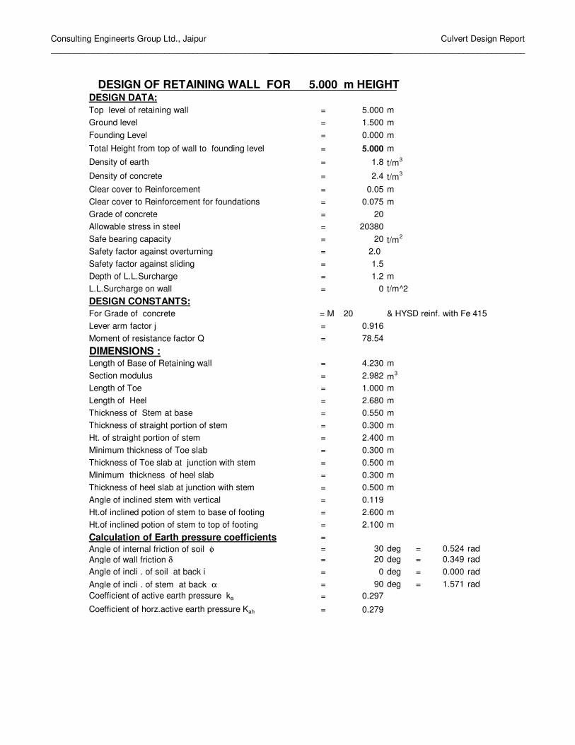
Top of Earth fill
Top level of wall
0.30
2.400
Earth Fill
5.000
Ground level
Heel 0.500 Toe0.300 0.300
2.680 0.550 1.0004.230
Str
aigh
t por
tion
of s
tem
=
9
13
2
3
4 6
5711 14
1
8
10
12
Consulting Engineerts Group Ltd., Jaipur________________________________________________________________________
Culvert Design Report______________________________________________________
DESIGN OF RETAINING WALL FOR 5.000 m HEIGHTDESIGN DATA:Top level of retaining wall = 5.000 mGround level = 1.500 mFounding Level = 0.000 m
Total Height from top of wall to founding level = 5.000 m
Density of earth = 1.8 t/m3
Density of concrete = 2.4 t/m3
Clear cover to Reinforcement = 0.05 mClear cover to Reinforcement for foundations = 0.075 mGrade of concrete = 20Allowable stress in steel = 20380Safe bearing capacity = 20 t/m2
Safety factor against overturning = 2.0 Safety factor against sliding = 1.5Depth of L.L.Surcharge = 1.2 mL.L.Surcharge on wall = 0 t/m^2DESIGN CONSTANTS:For Grade of concrete = M 20 & HYSD reinf. with Fe 415Lever arm factor j = 0.916Moment of resistance factor Q = 78.54
DIMENSIONS :Length of Base of Retaining wall = 4.230 mSection modulus = 2.982 m3
Length of Toe = 1.000 mLength of Heel = 2.680 mThickness of Stem at base = 0.550 mThickness of straight portion of stem = 0.300 mHt. of straight portion of stem = 2.400 mMinimum thickness of Toe slab = 0.300 mThickness of Toe slab at junction with stem = 0.500 mMinimum thickness of heel slab = 0.300 mThickness of heel slab at junction with stem = 0.500 mAngle of inclined stem with vertical = 0.119Ht.of inclined potion of stem to base of footing = 2.600 mHt.of inclined potion of stem to top of footing = 2.100 mCalculation of Earth pressure coefficients =Angle of internal friction of soil φ = 30 deg = 0.524 radAngle of wall friction δ = 20 deg = 0.349 radAngle of incli . of soil at back i = 0 deg = 0.000 radAngle of incli . of stem at back α = 90 deg = 1.571 radCoefficient of active earth pressure ka = 0.297
Coefficient of horz.active earth pressure Kah = 0.279

Consulting Engineerts Group Ltd., Jaipur________________________________________________________________________
Culvert Design Report______________________________________________________
Calculation of Forces & moments due to Vertical Forces
S.No. DescriptionArea
Factorwidth Depth Density Weight
C.G. from Toe
Moment about
toe1 1.0 0.300 4.5 2.4 3.240 1.150 3.7262 0.5 0.250 2.1 2.4 0.630 1.383 0.8713 0.5 2.680 0.2 2.4 0.643 2.443 1.5724 1.0 2.680 0.3 2.4 1.930 2.890 5.5775 0.5 1.000 0.2 2.4 0.240 0.667 0.1606 1.0 1.000 0.3 2.4 0.720 0.500 0.3607 Wt.of intmdt.portion 1.0 0.550 0.5 2.4 0.660 1.275 0.8428 1.0 2.930 2.4 1.8 12.658 2.765 34.9989 0.5 0.250 2.1 1.8 0.473 1.467 0.69310 1.0 2.680 2.1 1.8 10.130 2.890 29.27711 0.5 2.680 0.2 1.8 0.482 3.337 1.61012 0.0 2.930 1.465 1.8 0.000 3.254 0.00013 0.0 1 1.0 1.8 0.000 0.500 0.00014 0.0 1 0.2 1.8 0.000 0.333 0.00015 L.L.Surcharge 0.0 2.93 1.2 1.8 0.000 2.765 0.000
Total forces = 31.806 79.68Total Vertical load = 31.81 Total Restoring moment = 79.68
Horz. components of Earth Pressure
S.No. Horz. Press due to Area
factorPressure
kahγh Height Horz. ForceC.G.
from Toe
Moment about
toe1 0.5 2.514 5 6.286 2.100 13.202 1 0.603 5 3.017 2.500 7.54
Total forces = 9.303 20.74
20.74 tm Total vertical load V = 31.806 t79.68 tm Total Horz. Force = 9.303 t
3.84 OK > 2Check for sliding : Coefficient of base friction = 0.500Total vertical force = 31.806 tResisting force = 15.90 tF.O.S 1.71 OK > 1.5
2.505 m0.390 m
Moment about c/l raft = 12.416 t-mNet moment about base Mn = 8.328 t-mCalculation of Base Pressure Base pressure due to vertical load V/A = 7.52 Pressure at toe = 10.31 t/m2
Base pressure due to moment Mn/Z = 2.793 Pressure at heel= 4.73 t/m2
Total overturning moment Mo =
Eccentricity of loads w.r.t. c/l raft =
Wt. of soil above toe slab
Factor of safety against overturning Mr/Mo =
C.G. of loads from toe = Mr/V =
Total restoring moment Mr =
L.L.Surcharge
Wt. of soil above heel slab
Active Earth Pressure
Wt of stem
Wt of heel slab
Wt of toe slab

Consulting Engineerts Group Ltd., Jaipur________________________________________________________________________
Culvert Design Report______________________________________________________
CALCULATION OF DESIGN PRESSURES1-1 2-2 3-3 4-4 5-5
10.312 8.991 8.265 4.726 9.7610.720 1.200 9.300 9.180 1.0009.592 7.791 -1.035 -4.454 8.761
** Positive net pressure means upward pressure & negative net pressure means downward pressure
4 3 2 5 1 d
Heel Toe
2.680 1.000
4.230 4 3 2 5 1DESIGN OF TOE SLAB
Bending Moment at face of stem = 4.50 t-mEffective depth required = 0.239 m
= 0.417 > reqd 0.239Area of Reinforcement reqd.at bottom = 5.78 cm2 HENCE SAFE
= 5.35 tBending moment at sec 5-5 = 1.58 t-mNet shear force at sec 5-5=S-Ms*tanβ/d1 = 4.40 tDepth of slab at section 5-5 = 0.417 Effective depth d1 = 0.332 mNominal Shear stress = 10.55 t/m2
Permissible shear strsss is calculated as per cl.304.7.1.3 of IRC:21-2000100As/bd = 0.174 %Therefore Permissible shear strsss = 19.35 t/m2 HENCE SAFEDESIGN OF HEEL SLAB
11.90 t-mEffective depth required = 0.389 m
0.415 mReinforcement reqd.at top = 15.36 cm2
7.35 tBending moment at face Ms = 11.90 t-mNet shear force =S-Ms*tanβ/d1 = 5.21 tNominal Shear stress = 12.57 t/m2
Permissible shear strsss is calculated as per cl.304.7.1.3 of IRC:21-2000100As/bd = 0.370 %Therefore Permissible shear strsss = 26.36 t/m2 HENCE SAFEFOR CURTAILMENTShear Force at distance from stem = 2.259Bending Moment at distance 1.500 m from face of stem = 2.27Effective depth required = 0.170 mEffective depth provided = 0.305 > reqd 0.170
Curtailment Length = 1.805Area of Reinforcement reqd.at bottom = 3.99 cm2
SectionUpward pressureDownward PressureNet pressure
Reinforcement calculation
Effective depth of slab at face of stem =
Shear force at face of stem S =
Effective depth provided at face of stem
Shear force at distance d from stem Shear check:
Shear check:
Bending Moment at face of stem =

Consulting Engineerts Group Ltd., Jaipur________________________________________________________________________
Culvert Design Report______________________________________________________
DESIGN OF STEM BASESection A
Height of Base of stem from top of earth fill = 4.5 mHeight of Base of stem below straight portion = 2.1 m
S.No.Area
factorPressure
ka.g.h HeightHorz. Force
C.G. from base
Moment about base
1 0.5 2.263 4.5 5.092 1.890 9.62
2 1 0.603 4.5 2.716 2.250 6.11
Total = 7.81 15.73Total Horizontal Force 7.81 tTotal Moment about base 15.73 tmDesign bending moment 15.73 t-mEffective depth required 0.448 mThickness of stem at base 0.550 mEffective depth provided 0.488 > 0.448 HENCE SAFEArea of steel reqd. 17.29 cm2
Shear force at base of stem 7.81 tBending moment at base 15.73 t-mNet shear force 3.97 tNominal Shear stress 8.13 t/m2
Permissible shear strsss is calculated as per cl.304.7.1.3 of IRC:21-2000= 0.35 %
Therefore Permissible shear strsss 25.86 t/m2 HENCE SAFE
Horz. Press due to
ActiveEarthPressure
Shear check:
100As/bd
L.L.Surcharge

Consulting Engineers Group Ltd., Jaipur_______________________________________________________________
Culvert Design Report_______________________________________________________
Top of Earth fill
Top level of wall
0.30
2.400
Earth Fill
6.000
Ground level
Heel 0.600 Toe0.300 0.300
3.06 0.700 1.1754.935
Str
aigh
t por
tion
of s
tem
=
9
13
2
3
4 6
5711 14
1
8
10
12

Consulting Engineers Group Ltd., Jaipur_______________________________________________________________
Culvert Design Report_______________________________________________________
DESIGN OF RETAINING WALL FOR 6.000 m HEIGHTDESIGN DATA:Top level of retaining wall = 6.000 mGround level = 2.000 mFounding Level = 0.000 m
Total Height from top of wall to founding level = 6.000 m
Density of earth = 1.8 t/m3
Density of concrete = 2.4 t/m3
Clear cover to Reinforcement = 0.05 mClear cover to Reinforcement for foundations = 0.075 mGrade of concrete = 20Allowable stress in steel = 20380Safe bearing capacity = 20 t/m2
Safety factor against overturning = 2.0 Safety factor against sliding = 1.5Depth of L.L.Surcharge = 1.2 mL.L.Surcharge on wall = 0 t/m^2DESIGN CONSTANTS:For Grade of concrete = M 20 & HYSD reinf. with Fe 415Lever arm factor j = 0.916Moment of resistance factor Q = 78.54
DIMENSIONS :Length of Base of Retaining wall = 4.935 mSection modulus = 4.059 m3
Length of Toe = 1.175 mLength of Heel = 3.060 mThickness of Stem at base = 0.700 mThickness of straight portion of stem = 0.300 mHt. of straight portion of stem = 2.400 mMinimum thickness of Toe slab = 0.300 mThickness of Toe slab at junction with stem = 0.600 mMinimum thickness of heel slab = 0.300 mThickness of heel slab at junction with stem = 0.600 mAngle of inclined stem with vertical = 0.133Ht.of inclined potion of stem to base of footing = 3.600 mHt.of inclined potion of stem to top of footing = 3.000 mCalculation of Earth pressure coefficients =Angle of internal friction of soil φ = 30 deg = 0.524 radAngle of wall friction δ = 20 deg = 0.349 radAngle of incli . of soil at back i = 0 deg = 0.000 radAngle of incli . of stem at back α = 90 deg = 1.571 radCoefficient of active earth pressure ka = 0.297
Coefficient of horz.active earth pressure Kah = 0.279

Consulting Engineers Group Ltd., Jaipur_______________________________________________________________
Culvert Design Report_______________________________________________________
Calculation of Forces & moments due to Vertical Forces
S.No. DescriptionArea
Factorwidth Depth Density Weight
C.G. from Toe
Moment about
toe1 1.0 0.300 5.4 2.4 3.888 1.325 5.1522 0.5 0.400 3 2.4 1.440 1.608 2.3163 0.5 3.060 0.3 2.4 1.102 2.895 3.1894 1.0 3.060 0.3 2.4 2.203 3.405 7.5025 0.5 1.175 0.3 2.4 0.423 0.783 0.3316 1.0 1.175 0.3 2.4 0.846 0.588 0.4977 Wt.of intmdt.portion 1.0 0.700 0.6 2.4 1.008 1.525 1.5378 1.0 3.460 2.4 1.8 14.947 3.205 47.9069 0.5 0.400 3 1.8 1.080 1.742 1.88110 1.0 3.060 3 1.8 16.524 3.405 56.26411 0.5 3.060 0.3 1.8 0.826 3.915 3.23512 0.0 3.460 1.73 1.8 0.000 3.783 0.00013 0.0 1.175 1.4 1.8 0.000 0.588 0.00014 0.0 1.175 0.3 1.8 0.000 0.392 0.00015 L.L.Surcharge 0.0 3.46 1.2 1.8 0.000 3.205 0.000
Total forces = 44.287 129.81Total Vertical load = 44.29 Total Restoring moment = 129.81
Horz. components of Earth Pressure
S.No.Area
factorPressure
kahγh Height Horz. ForceC.G. from Toe
Moment about
toe1 0.5 3.017 6 9.052 2.520 22.812 1 0.603 6 3.621 3.000 10.86
Total forces = 12.673 33.67
33.67 tm Total vertical load V = 44.287 t129.81 tm Total Horz. Force = 12.673 t
3.85 OK > 2Check for sliding : Coefficient of base friction = 0.500Total vertical force = 44.287 tResisting force = 22.14 tF.O.S 1.75 OK > 1.5
2.931 m0.464 m
Moment about c/l raft = 20.531 t-mNet moment about base Mn = 13.142 t-mCalculation of Base Pressure Base pressure due to vertical load V/A = 8.97 Pressure at toe = 12.21 t/m2
Base pressure due to moment Mn/Z = 3.238 Pressure at heel= 5.74 t/m2
Total overturning moment Mo =
Eccentricity of loads w.r.t. c/l raft =
Wt. of soil above toe slab
Factor of safety against overturning Mr/Mo =
C.G. of loads from toe = Mr/V =
Total restoring moment Mr =
L.L.Surcharge
Wt. of soil above heel slab
Active Earth Pressure
Horz. Press due to
Wt of stem
Wt of heel slab
Wt of toe slab

Consulting Engineers Group Ltd., Jaipur_______________________________________________________________
Culvert Design Report_______________________________________________________
CALCULATION OF DESIGN PRESSURES1-1 2-2 3-3 4-4 5-5
12.212 10.670 9.752 5.736 11.5310.720 1.440 11.160 10.980 1.122
11.492 9.230 -1.408 -5.244 10.409
** Positive net pressure means upward pressure & negative net pressure means downward pressure
4 3 2 5 1 d
Heel Toe
3.060 1.175
4.935 4 3 2 5 1DESIGN OF TOE SLAB
Bending Moment at face of stem = 7.41 t-mEffective depth required = 0.307 m
= 0.519 > reqd 0.307Area of Reinforcement reqd.at bottom = 7.65 cm2 HENCE SAFE
= 7.18 tBending moment at sec 5-5 = 2.40 t-mNet shear force at sec 5-5=S-Ms*tanβ/d1 = 5.58 tDepth of slab at section 5-5 = 0.467 Effective depth d1 = 0.382 mNominal Shear stress = 11.95 t/m2
Permissible shear strsss is calculated as per cl.304.7.1.3 of IRC:21-2000100As/bd = 0.200 %Therefore Permissible shear strsss = 20.40 t/m2 HENCE SAFEDESIGN OF HEEL SLAB
18.56 t-mEffective depth required = 0.486 m
0.517 m Reinforcement reqd.at top = 19.24 cm2
10.18 tBending moment at face Ms = 18.56 t-mNet shear force =S-Ms*tanβ/d1 = 6.66 tNominal Shear stress = 12.88 t/m2
Permissible shear strsss is calculated as per cl.304.7.1.3 of IRC:21-2000100As/bd = 0.372 %Therefore Permissible shear strsss = 26.42 t/m2 HENCE SAFEFOR CURTAILMENTShear Force at distance from stem = 2.991Bending Moment at distance 2.000 m from face of stem = 2.17Effective depth required = 0.166 mEffective depth provided = 0.321 > reqd 0.166
Curtailment Length = 2.321Area of Reinforcement reqd.at bottom = 3.62 cm2
SectionUpward pressureDownward PressureNet pressure
Reinforcement calculation
Effective depth of slab at face of stem =
Shear force at face of stem S =
Effective depth provided at face of stem
Shear force at distance d from stem Shear check:
Shear check:
Bending Moment at face of stem =

Consulting Engineers Group Ltd., Jaipur_______________________________________________________________
Culvert Design Report_______________________________________________________
DESIGN OF STEM BASESection A
Height of Base of stem from top of earth fill = 5.4 mHeight of Base of stem below straight portion = 3 m
S.No.Area
factorPressure
ka.g.h HeightHorz. Force
C.G. from base
Moment about base
1 0.5 2.716 5.4 7.332 2.268 16.63
2 1 0.603 5.4 3.259 2.700 8.80
Total = 10.59 25.43Total Horizontal Force 10.59 tTotal Moment about base 25.43 tmDesign bending moment 25.43 t-mEffective depth required 0.569 mThickness of stem at base 0.700 mEffective depth provided 0.640 > 0.569 HENCE SAFEArea of steel reqd. 21.28 cm2
Shear force at base of stem 10.59 tBending moment at base 25.43 t-mNet shear force 5.29 tNominal Shear stress 8.27 t/m2
Permissible shear strsss is calculated as per cl.304.7.1.3 of IRC:21-2000= 0.33 %
Therefore Permissible shear strsss 25.13 t/m2 HENCE SAFE
L.L.Surcharge
Horz. Press due to
ActiveEarthPressure
Shear check:
100As/bd

Consulting Engineers Group Ltd., Jaipur_______________________________________________________________
Culvert Design Report_______________________________________________________
Top of Earth fill
Top level of wall
0.30
2.400
Earth Fill
7.000
Ground level
Heel 0.625 Toe0.300 0.300
3.10 0.800 1.2005.100
Str
aigh
t por
tion
of s
tem
=
9
13
2
3
4 6
5711 14
1
8
10
12

Consulting Engineers Group Ltd., Jaipur_______________________________________________________________
Culvert Design Report_______________________________________________________
DESIGN OF RETAINING WALL FOR 7.000 m HEIGHTDESIGN DATA:Top level of retaining wall = 7.000 mGround level = 2.000 mFounding Level = 0.000 m
Total Height from top of wall to founding level = 7.000 m
Density of earth = 1.8 t/m3
Density of concrete = 2.4 t/m3
Clear cover to Reinforcement = 0.05 mClear cover to Reinforcement for foundations = 0.075 mGrade of concrete = 20Allowable stress in steel = 20380Safe bearing capacity = 20 t/m2
Safety factor against overturning = 2.0 Safety factor against sliding = 1.5Depth of L.L.Surcharge = 1.2 mL.L.Surcharge on wall = 0 t/m^2DESIGN CONSTANTS:For Grade of concrete = M 20 & HYSD reinf. with Fe 415Lever arm factor j = 0.916Moment of resistance factor Q = 78.54
DIMENSIONS :Length of Base of Retaining wall = 5.100 mSection modulus = 4.335 m3
Length of Toe = 1.200 mLength of Heel = 3.100 mThickness of Stem at base = 0.800 mThickness of straight portion of stem = 0.300 mHt. of straight portion of stem = 2.400 mMinimum thickness of Toe slab = 0.300 mThickness of Toe slab at junction with stem = 0.625 mMinimum thickness of heel slab = 0.300 mThickness of heel slab at junction with stem = 0.625 mAngle of inclined stem with vertical = 0.126Ht.of inclined potion of stem to base of footing = 4.600 mHt.of inclined potion of stem to top of footing = 3.975 mCalculation of Earth pressure coefficients =Angle of internal friction of soil φ = 30 deg = 0.524 radAngle of wall friction δ = 20 deg = 0.349 radAngle of incli . of soil at back i = 0 deg = 0.000 radAngle of incli . of stem at back α = 90 deg = 1.571 radCoefficient of active earth pressure ka = 0.297
Coefficient of horz.active earth pressure Kah = 0.279

Consulting Engineers Group Ltd., Jaipur_______________________________________________________________
Culvert Design Report_______________________________________________________
Calculation of Forces & moments due to Vertical Forces
S.No. DescriptionArea
Factorwidth Depth Density Weight
C.G. from Toe
Moment about
toe1 1.0 0.300 6.375 2.4 4.590 1.350 6.1972 0.5 0.500 3.975 2.4 2.385 1.667 3.9753 0.5 3.100 0.325 2.4 1.209 3.033 3.6674 1.0 3.100 0.3 2.4 2.232 3.550 7.9245 0.5 1.200 0.325 2.4 0.468 0.800 0.3746 1.0 1.200 0.3 2.4 0.864 0.600 0.5187 Wt.of intmdt.portion 1.0 0.800 0.625 2.4 1.200 1.600 1.9208 1.0 3.600 2.4 1.8 15.552 3.3 51.3229 0.5 0.500 3.975 1.8 1.789 1.833 3.27910 1.0 3.100 3.975 1.8 22.181 3.550 78.74111 0.5 3.100 0.325 1.8 0.907 4.067 3.68812 0.0 3.600 1.8 1.8 0.000 3.901 0.00013 0.0 1.2 1.4 1.8 0.000 0.600 0.00014 0.0 1.2 0.325 1.8 0.000 0.400 0.00015 L.L.Surcharge 0.0 3.6 1.2 1.8 0.000 3.300 0.000
Total forces = 53.376 161.60Total Vertical load = 53.38 Total Restoring moment = 161.60
Horz. components of Earth Pressure
S.No.Area
factorPressure
kahγh Height Horz. ForceC.G. from Toe
Moment about
toe1 0.5 3.520 7 12.321 2.940 36.222 1 0.603 7 4.224 3.500 14.78
Total forces = 16.545 51.01
51.01 tm Total vertical load V = 53.376 t161.60 tm Total Horz. Force = 16.545 t
3.17 OK > 2Check for sliding : Coefficient of base friction = 0.500Total vertical force = 53.376 tResisting force = 26.69 tF.O.S 1.61 OK > 1.5
3.028 m0.478 m
Moment about c/l raft = 25.496 t-mNet moment about base Mn = 25.512 t-mCalculation of Base Pressure Base pressure due to vertical load V/A = 10.47 Pressure at toe = 16.35 t/m2
Base pressure due to moment Mn/Z = 5.885 Pressure at heel= 4.58 t/m2
Total overturning moment Mo =
Eccentricity of loads w.r.t. c/l raft =
Wt. of soil above toe slab
Factor of safety against overturning Mr/Mo =
C.G. of loads from toe = Mr/V =
Total restoring moment Mr =
L.L.Surcharge
Wt. of soil above heel slab
Active Earth Pressure
Horz. Press due to
Wt of stem
Wt of heel slab
Wt of toe slab

Consulting Engineers Group Ltd., Jaipur_______________________________________________________________
Culvert Design Report_______________________________________________________
CALCULATION OF DESIGN PRESSURES1-1 2-2 3-3 4-4 5-5
16.351 13.582 11.735 4.581 15.0960.720 1.500 12.975 12.780 1.146
15.631 12.082 -1.240 -8.199 13.949
** Positive net pressure means upward pressure & negative net pressure means downward pressure
4 3 2 5 1 d
Heel Toe
3.100 1.200
5.100 4 3 2 5 1DESIGN OF TOE SLAB
Bending Moment at face of stem = 10.40 t-mEffective depth required = 0.364 m
= 0.544 > reqd 0.364Area of Reinforcement reqd.at bottom = 10.24 cm2 HENCE SAFE
= 9.70 tBending moment at sec 5-5 = 3.24 t-mNet shear force at sec 5-5=S-Ms*tanβ/d1 = 7.47 tDepth of slab at section 5-5 = 0.478 Effective depth d1 = 0.393 mNominal Shear stress = 15.63 t/m2
Permissible shear strsss is calculated as per cl.304.7.1.3 of IRC:21-2000100As/bd = 0.261 %Therefore Permissible shear strsss = 22.79 t/m2 HENCE SAFEDESIGN OF HEEL SLAB
28.25 t-mEffective depth required = 0.600 m
0.542 m Reinforcement reqd.at top = 27.92 cm2
14.63 tBending moment at face Ms = 28.25 t-mNet shear force =S-Ms*tanβ/d1 = 9.17 tNominal Shear stress = 16.91 t/m2
Permissible shear strsss is calculated as per cl.304.7.1.3 of IRC:21-2000100As/bd = 0.515 %Therefore Permissible shear strsss = 30.91 t/m2 HENCE SAFEFOR CURTAILMENTShear Force at distance from stem = 5.204Bending Moment at distance 2.000 m from face of stem = 3.96Effective depth required = 0.225 mEffective depth provided = 0.332 > reqd 0.225
Curtailment Length = 2.332Area of Reinforcement reqd.at bottom = 6.39 cm2
SectionUpward pressureDownward PressureNet pressure
Reinforcement calculation
Effective depth of slab at face of stem =
Shear force at face of stem S =
Effective depth provided at face of stem
Shear force at distance d from stem Shear check:
Shear check:
Bending Moment at face of stem =

Consulting Engineers Group Ltd., Jaipur_______________________________________________________________
Culvert Design Report_______________________________________________________
DESIGN OF STEM BASESection A
Height of Base of stem from top of earth fill = 6.375 mHeight of Base of stem below straight portion = 3.975 m
S.No.Area
factorPressure
ka.g.h HeightHorz. Force
C.G. from base
Moment about base
1 0.5 3.206 6.375 10.219 2.678 27.36
2 1 0.603 6.375 3.847 3.188 12.26
Total = 14.07 39.62Total Horizontal Force 14.07 tTotal Moment about base 39.62 tmDesign bending moment 39.62 t-mEffective depth required 0.710 mThickness of stem at base 0.800 mEffective depth provided 0.740 > 0.710 HENCE SAFEArea of steel reqd. 28.68 cm2
Shear force at base of stem 14.07 tBending moment at base 39.62 t-mNet shear force 7.33 tNominal Shear stress 9.91 t/m2
Permissible shear strsss is calculated as per cl.304.7.1.3 of IRC:21-2000= 0.39 %
Therefore Permissible shear strsss 26.93 t/m2 HENCE SAFE
L.L.Surcharge
Horz. Press due to
ActiveEarthPressure
Shear check:
100As/bd