Embed Size (px)
Citation preview
Original Instructions
Installation, Operation & Maintenance ManualSentry CPS SamplerCorrosion Sampler
S-SW-IOM-00252-16 8-16
2 Sentry Equipment Corp
Do not install, maintain, or operate this equipment without reading, understanding, and following the appropriate Sentry Equipment Corp instructions. Otherwise, injury, damage, or both may result.
Copyright
© 2016 by Sentry Equipment Corp. All rights reserved. All product and company names are property of their respective owners. This document contains proprietary information. No part of this document may be photocopied or reproduced without the prior written consent of Sentry Equipment Corp.
Limit of Liability
Sentry Equipment Corp, its employees, agents, and the authors and contributors to this document specifi cally disclaim all liabilities and warranties, express or implied (including warranties of merchantability and fi tness for a particular purpose), for the accuracy, currency, completeness, and/or reliability of the information contained herein and/or for the fi tness for any particular use and/or for the performance of any material and/or equipment selected in whole or part with the user of/or in reliance upon information contained herein. Selection of materials and/or equipment is at the sole risk of the user of this publication.
Note
The information contained in this document is subject to change without notice.
Table of Contents
Safety Information . . . . . . . . . . . . . . . . . . . . . . . . . 3
General Safety Precautions . . . . . . . . . . . . . . . . . 4
General Description . . . . . . . . . . . . . . . . . . . . . . . . 5
Installation . . . . . . . . . . . . . . . . . . . . . . . . . . . . . . . . . 10
Operation . . . . . . . . . . . . . . . . . . . . . . . . . . . . . . . . . . 12
Maintenance . . . . . . . . . . . . . . . . . . . . . . . . . . . . . . . 14
Consumables . . . . . . . . . . . . . . . . . . . . . . . . . . . . . . 19
Spare Parts . . . . . . . . . . . . . . . . . . . . . . . . . . . . . . . . . 20
Standard Warranty . . . . . . . . . . . . . . . . . . . . . . . . . 21
Customer Support . . . . . . . . . . . . . . . . . . . . . . . . . . 22
Sentry CPS Sampler 3
Safety InformationPlease read the entire manual before attempting to unpack, set up, or operate this product. Pay careful attention to all Warnings, Cautions, and Notes. Failure to do so could result in serious personal injury and/or equipment damage.
Use of Hazard Information
If multiple hazards exist, the signal word corresponding to the greatest hazard shall be used.
Defi nitions
DANGER indicates a hazardous situation which, if not avoided, will result in death or serious injury .
WARNING indicates a hazardous situation which, if not avoided, could result in death or serious injury .
CAUTION, used with the safety alert symbol, indicates a hazardous situation which, if not avoided, could result in minor or moderate injury .
NOTICE is used to address practices not related to personal injury .
 NOTEInformation that requires special emphasis .
 TIPAlternate techniques or clarifying information.
SHALL: This word is understood to be mandatory.
SHOULD: This word is understood to be advisory.
4 Sentry Equipment Corp
General Safety Precautions
Product Selection, Installation, and Use
Improper selection, installation, or use can cause personal injury or property damage . It is solely the responsibility of users, through their own analysis and testing, to select products suitable for their specifi c application requirements, ensure they are properly maintained, and limit their use to their intended purpose .
Follow proper local, state, and federal regulations for proper installation and operational requirements .
Always use caution and common sense when working with any chemical . Read the product label and Material Safety Data Sheets (MSDS) carefully and follow the instructions exactly .
Potential Equipment Hazards
Hot surfaces! This equipment may have very hot surfaces . If an operator contacts a hot surface, injury may occur . Use protective clothing to prevent injury . If other equipment comes in contact with a hot surface, damage to the equipment may occur . Ensure the area around this equipment is kept clear to prevent this damage from occurring .
High pressures! This equipment may contain fl uids at very high pressures . Prior to installing, removing, or maintaining this equipment, ensure that the equipment is isolated from all connecting piping, the equipment is depressurized, the contents have been drained, and the equipment is cool .
Sentry CPS Sampler 5
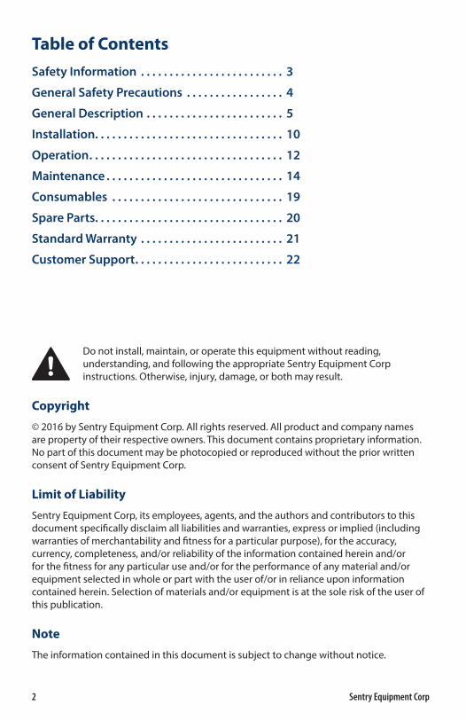
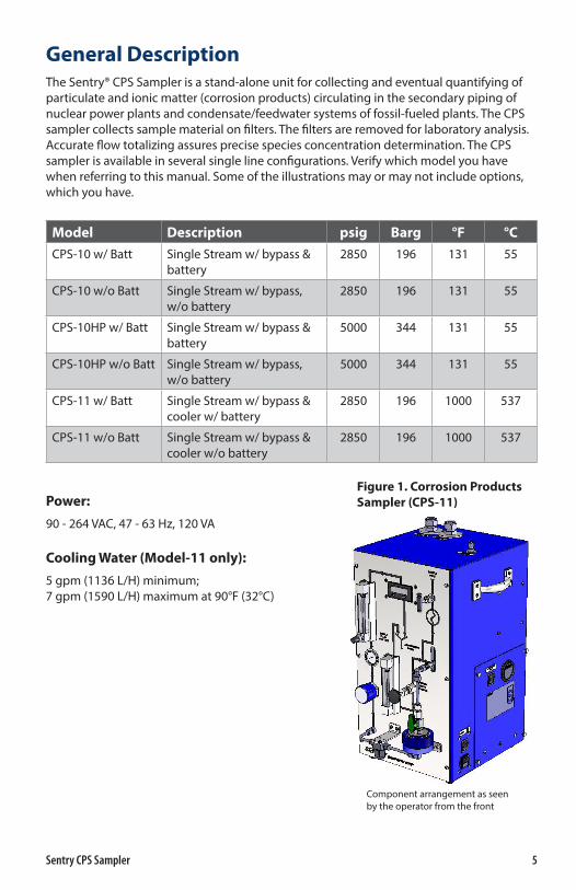
General DescriptionThe Sentry® CPS Sampler is a stand-alone unit for collecting and eventual quantifying of particulate and ionic matter (corrosion products) circulating in the secondary piping of nuclear power plants and condensate/feedwater systems of fossil-fueled plants. The CPS sampler collects sample material on filters. The filters are removed for laboratory analysis. Accurate flow totalizing assures precise species concentration determination. The CPS sampler is available in several single line configurations. Verify which model you have when referring to this manual. Some of the illustrations may or may not include options, which you have.
Model Description psig Barg °F °C
CPS-10 w/ Batt Single Stream w/ bypass & battery
2850 196 131 55
CPS-10 w/o Batt Single Stream w/ bypass, w/o battery
2850 196 131 55
CPS-10HP w/ Batt Single Stream w/ bypass & battery
5000 344 131 55
CPS-10HP w/o Batt Single Stream w/ bypass, w/o battery
5000 344 131 55
CPS-11 w/ Batt Single Stream w/ bypass & cooler w/ battery
2850 196 1000 537
CPS-11 w/o Batt Single Stream w/ bypass & cooler w/o battery
2850 196 1000 537
Power:
90 - 264 VAC, 47 - 63 Hz, 120 VA
Cooling Water (Model-11 only):
5 gpm (1136 L/H) minimum; 7 gpm (1590 L/H) maximum at 90°F (32°C)
Component arrangement as seen by the operator from the front
Figure 1. Corrosion Products Sampler (CPS-11)
6 Sentry Equipment Corp
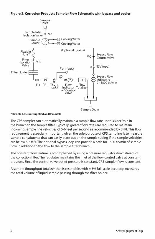
Figure 2. Corrosion Products Sampler Flow Schematic with bypass and cooler
Sample Drain
Cooling WaterCooling Water
V-1Sample Inlet
Isolation ValveSampleCooler
SampleInlet
(Optional Bypass)
V-2
V-3
Bypass FlowControl Valve
TSV (opt.)
Bypass FlowIndicators0 - 1800 cc/min
RV-1 (opt.)
F-1 PR-1 TSV-1(opt.)
FlowIndicator
w/ ControlValve
FlowTotalizer
FlexibleHose*
FilterIsolation
Valve
Filter Holder
*Flexible hose not supplied on HP models
The CPS sampler can automatically maintain a sample flow rate up to 330 cc/min in the branch to the sample filter. Typically, greater flow rates are required to maintain incoming sample line velocities of 5-6 feet per second as recommended by EPRI. This flow requirement is especially important, given the sole purpose of CPS sampling is to measure sample constituents that can easily plate out on the sample tubing if the sample velocities are below 5-6 ft/s. The optional bypass loop can provide a path for 1500 cc/min of sample flow in addition to the flow to the sample filter branch.
The constant flow feature is accomplished by using a pressure regulator downstream of the collection filter. The regulator maintains the inlet of the flow control valve at constant pressure. Since the control valve outlet pressure is constant, CPS sampler flow is constant.
A sample throughput totalizer that is resettable, with ± 3% full-scale accuracy, measures the total volume of liquid sample passing through the filter holder.
Sentry CPS Sampler 7
Standard Filter Holder
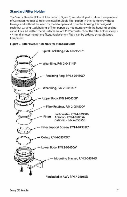
The Sentry Standard Filter Holder (refer to Figure 3) was developed to allow the operators of Corrosion Product Samplers to install multiple filter papers in their samplers without leakage and without the need for tools to open and close the housing. It is designed such that varying stack heights of filter papers do not interfere with the housing’s sealing capabilities. All wetted metal surfaces are of T316SS construction. The filter holder accepts 47 mm diameter membrane filters. Replacement filters can be ordered through Sentry Equipment.
Figure 3. Filter Holder Assembly for Standard Units
8 Sentry Equipment Corp
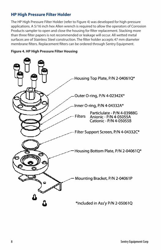
HP High Pressure Filter Holder
The HP High Pressure Filter Holder (refer to Figure 4) was developed for high-pressure applications. A 5/16 inch hex Allen wrench is required to allow the operators of Corrosion Products sampler to open and close the housing for filter replacement. Stacking more than three filter papers is not recommended or leakage will occur. All wetted metal surfaces are of Stainless Steel construction. The filter holder accepts 47 mm diameter membrane filters. Replacement filters can be ordered through Sentry Equipment.
Figure 4. HP High Pressure Filter Housing
Sentry CPS Sampler 9
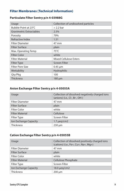
Filter Membranes (Technical Information)
Particulate Filter Sentry p/n 4-03988G
Usage Collection of undissolved particlesBubble Point at 23°C > 2.2 barGravimetric Extractables 2.5%Porosity 79%Refractive Index 1.51Filter Diameter 47 mmFilter Surface plainMax. Operating Temp 75°CFilter Color whiteFilter Material Mixed Cellulose EstersFilter Type Screen FilterFilter Pore Size 0.45 μmWettability HydrophilicQty/Pkg 100Thickness 180 μm
Anion Exchange Filter Sentry p/n 4-05055A
Usage Collection of dissolved negatively charged ions (anions) (i.e., Cl-, Br-, OH-)
Filter Diameter 47 mmFilter Surface plainFilter Color whiteFilter Material Cellulose Filter Type Screen FilterIon Exchange Capacity 1.7 μeq/cm2Thickness 230 μm
Cation Exchange Filter Sentry p/n 4-05055B
Usage Collection of dissolved positively charged ions (cations) (i.e., Fe+, Cu+, Na+, Mg+)
Filter Diameter 47 mmFilter Surface plainFilter Color whiteFilter Material Cellulose PhosphateFilter Type Screen FilterIon Exchange Capacity 18.0 μeq/cm2Thickness 200 μm
10 Sentry Equipment Corp
Liquid Totalizer
The liquid totalizer is a Pelton-type microturbine meter designed for low flow rates in water systems.
The totalizer can display flow rate, total volume and is resettable by the customer. The instrument has an accuracy of ±3.0% of its full scale value, which is 500 cc/min.
Installation
Lifting hazard . Use proper lifting techniques when handling this equipment .
The CPS sampler is designed to be portable to allow for sampling in numerous locations. Select a location that provides adequate support, operator accessibility, close proximity to the sample being analyzed, access to cooling water (if required) and access to a gravity drain. Samples in excess of 131°F/55°C will require cooling. It is highly recommended that the CPS sampler be installed in a high-pressure portion of the sample line to ensure the sample flow rate meets the EPRI guidelines for representative sampling.
Standard Customer Connections
� Sample Inlet: 1/4” Compression fitting
� Sample Outlet/Drain: 3/4” O.D. Tube Stub (SS) (See note below)
� Cooling Water Inlet/Outlet (if installed): 3/4” Compression fittings
 NOTESince the liquid effluent is at atmospheric pressure, the method of connection can be either soft (using hose clamps provided by others) or rigid tubing .
Filter Replacement - Standard Filter Housing (Refer to Figure 3)
Verify that the pressure regulator is fully closed (turned fully counterclockwise), the bypass flow control valve is fully closed, the sample inlet valve is fully closed and the filter inlet isolation valve is fully closed.
Open the collection filter housing and remove the filter retainer and any filter papers. The filter housing is opened by unscrewing the blue anodized retaining ring and removing the upper body. No tools are necessary.
Re-install the upper body and retaining ring and hand tighten only. Because the seal is made around the circumference of the housing and not the face, it is not necessary to use extreme force to close the filter holder. When the filter holder is properly assembled and tightened, the bottom edge of the retaining ring will be flush with the bottom of the lower housing.
Sentry CPS Sampler 11
Filter Replacement - HP High Pressure Filter Housing (Refer to Figure 4)
Verify that the pressure regulator is fully closed (turned fully counterclockwise), the bypass flow control valve is fully closed, the sample inlet valve is fully closed and the filter inlet isolation valve is fully closed.
Open the collection filter housing and remove the filter papers. The filter housing is opened by removing the six cap screws with a 5/16 inch hex Allen wrench.
Re-install the housing top plate. Place the six cap screws in their original locations and give each bolt a few turns, first one, then the one opposite, working around the housing in a star pattern. Try not to tighten adjacent bolts consecutively. Tighten with a 5/16 inch hex Allen wrench. Because the seal is made around the housing face, it is recommended to tighten the bolts using the opposite star pattern method. When the filter holder is properly assembled and tightened, it will not leak.
Establish cooling water flow to the sample cooler (if required).
Assure that cooling water is flowing before establishing sample flow .
Open all fluid sample supply valves. Open the inlet isolation valve. Open the filter inlet isolation valve and adjust both the pressure regulator and sample flow control valve to simultaneously give 14 psig on the downstream pressure gauge and near 75 cc/min on the flow indicator.
The system should be primed with liquid and flow started gradually . This will prevent trapped air or gas from being forced through the sensor at a high velocity that may damage the flow totalizer . If the flow through the unit exceeds 120% of the maximum rate (full scale), the flow totalizer may be damaged .
12 Sentry Equipment Corp
Operation
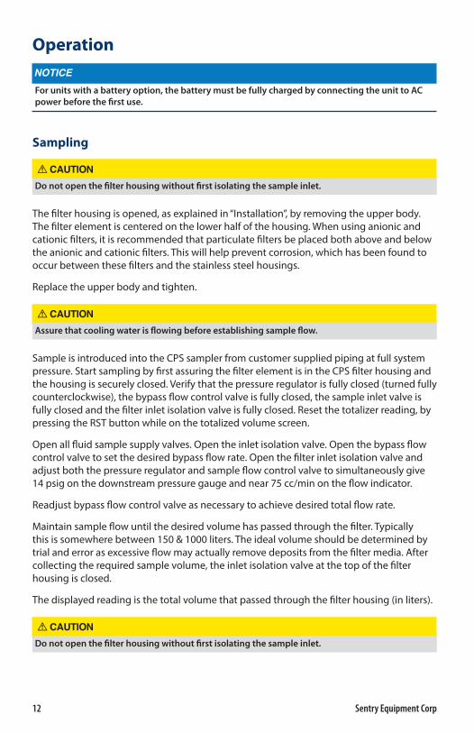
For units with a battery option, the battery must be fully charged by connecting the unit to AC power before the first use .
Sampling
Do not open the filter housing without first isolating the sample inlet .
The filter housing is opened, as explained in “Installation”, by removing the upper body. The filter element is centered on the lower half of the housing. When using anionic and cationic filters, it is recommended that particulate filters be placed both above and below the anionic and cationic filters. This will help prevent corrosion, which has been found to occur between these filters and the stainless steel housings.
Replace the upper body and tighten.
Assure that cooling water is flowing before establishing sample flow .
Sample is introduced into the CPS sampler from customer supplied piping at full system pressure. Start sampling by first assuring the filter element is in the CPS filter housing and the housing is securely closed. Verify that the pressure regulator is fully closed (turned fully counterclockwise), the bypass flow control valve is fully closed, the sample inlet valve is fully closed and the filter inlet isolation valve is fully closed. Reset the totalizer reading, by pressing the RST button while on the totalized volume screen.
Open all fluid sample supply valves. Open the inlet isolation valve. Open the bypass flow control valve to set the desired bypass flow rate. Open the filter inlet isolation valve and adjust both the pressure regulator and sample flow control valve to simultaneously give 14 psig on the downstream pressure gauge and near 75 cc/min on the flow indicator.
Readjust bypass flow control valve as necessary to achieve desired total flow rate.
Maintain sample flow until the desired volume has passed through the filter. Typically this is somewhere between 150 & 1000 liters. The ideal volume should be determined by trial and error as excessive flow may actually remove deposits from the filter media. After collecting the required sample volume, the inlet isolation valve at the top of the filter housing is closed.
The displayed reading is the total volume that passed through the filter housing (in liters).
Do not open the filter housing without first isolating the sample inlet .
Sentry CPS Sampler 13
The filter housing should be disassembled as shown in Figure 3 or Figure 4 and the sample filter assembly transported to the chemistry department for subsequent chemical and radioisotope analysis. The sample filter assembly should be bagged based on contamination levels and plant rules.
The Corrosion Products Sampler can be provided with two (2) optional Thermal Shut Off Valves (TSV-1). The TSV is a device designed to shut off sample flow to components down stream from the TSV if a thermal excursion (high temperature) occurs in the sample. The TSV is equipped with an indicating reset button. When the valve is in the tripped mode (closed), the red indicating band on the reset button is visible. If the valve is received in the tripped position it must be reset to allow sample flow. This is accomplished by pushing in the reset button until it latches. In conditions where ambient temperatures are above the valve trip point, it will be necessary to hold the reset button in until cooled sample allows the valve to latch.
If the TSV trips during sampling operations, isolate the analyzers on the line or lines affected. Correct the problem causing the excessive sample temperature and reset the TSV. It may be necessary to hold the reset button in momentarily until all high temperature sample is flushed from the system. After the TSV is reset, reinitialize sample flow to the analyzers.
Display
The display has two screens; the Total Volume screen and the Flow Rate screen. Pressing the T/R button will toggle between the two screens. An R on the left side of the screen indicates the Flow Rate screen. The Totalized Volume is displayed in liters. Pressing the RST button while the Totalized Volume is displayed will reset the Totalized Volume. Contact Sentry Equipment for instructions if you do not want the totalized volume operator resettable.
 NOTEDo not introduce instrument air into the totalizer . Keep the amount of air entering the totalizer to a minimum . Minimizing air entering the totalizer will minimize totalizer error .
14 Sentry Equipment Corp
MaintenanceThe CPS sampler requires little maintenance. Flushing with filtered demineralized water after each use can minimize problems. The filter holder, pressure regulator and flow indicator require some occasional inspection and maintenance. If the CPS sampler is not being used during freezing temperatures, it is recommended that the unit be drained to prevent damage.
Do not flow any gas through the flow meter . Do not blow unit dry with compressed air . This may damage the micro-turbine assembly . Do not exceed the pressure and temperature ranges for the unit .
Battery Maintenance
For units with a battery option, the battery voltage level can be checked by pressing the Battery Condition Test button. The meter will display the current condition of the battery charge. To prevent damage to the battery, the unit must be connected to AC power to recharge the battery when the meter reads 3 bars or less.
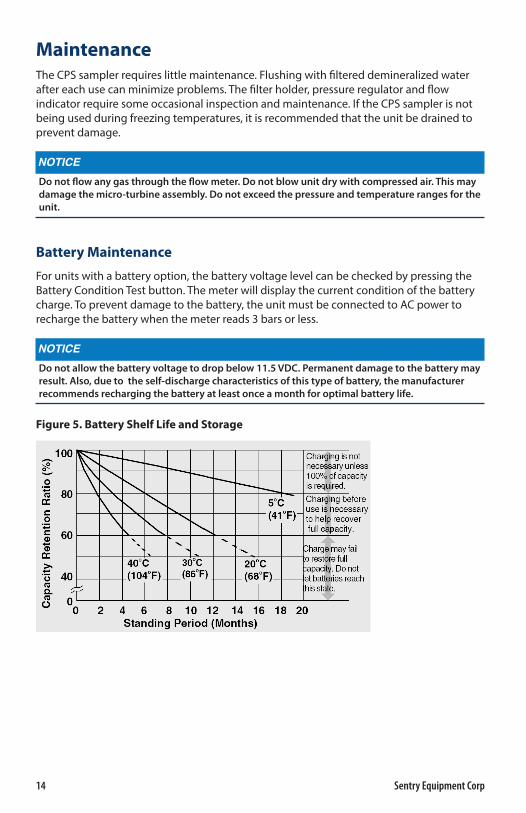
Do not allow the battery voltage to drop below 11 .5 VDC . Permanent damage to the battery may result . Also, due to the self-discharge characteristics of this type of battery, the manufacturer recommends recharging the battery at least once a month for optimal battery life .
Figure 5. Battery Shelf Life and Storage
Sentry CPS Sampler 15
Procedure to Verify CPS Flow Meter Calibration
1. Set flow rate of CPS sampler near 75 cc/min. Use the display to set flow rate. Flow Rate and Totalized Volume screens can be toggled by pressing the T/R button. An R on the left hand side of the screen indicates the Flow Rate screen.
2. Verify flow rate using the 250 cc graduated cylinder and stopwatch. Ensure there is no air in the sample line.
3. Confirm the displayed flow rate on the CPS sampler matches the graduated cylinder measurement within ± 3%.
 NOTEAveraging flow rate over an extended period of time will reduce the significance of human errors .
4. Use the 4000 cc graduated cylinder and reset the displayed total volume. Pressing the RST button resets the Total Volume. Fill graduated cylinder to 2000 cc. Maintain a flow rate near 75 cc/min. Ensure there is no air in the sample line.
5. When displayed total volume reaches 2000 cc, stop flow through CPS sampler and read value on graduated cylinder.
6. Verify the displayed total volume is within ± 4% or ± 80 cc of 2000 cc. If values are not within the stated range, repeat test.
7. If values exceed 16%, it is probable that damage to the sensor has occurred. If values are between 4% and 16%, recalibration is necessary.
Recalibrating Flow Meter
 NOTEIt is necessary to document programmed values prior to reprogramming the totalizer . Failure to do so will result in incorrect scaling and error in totalized volume . The factory calibrated values are located on the flow sensor unit .
If the totalizer/display stated value is within 16% of the actual value and a recalibration is desired, the totalizer and flow rate multipliers can be adjusted for a more accurate reading. Follow the procedure below. Ensure there is no entrapped air in the sample line. Entrapped air will cause excess error in the totalizer reading. If the totalizer/display stated value is not within 16% of the actual value, it is probable that the flow sensor has been damaged and will require replacement.
1. Disconnect power from the unit. Verify the display screen is on.
2. Place unit into calibration mode. On some models, using the meter calibration switch located on the CPS sampler will do this. Otherwise, remove the cover from the Flow Totalizer display enclosure, and then connect the female push-on disconnect (located at terminal 5 on the Flow Totalizer display) to the male push-on disconnect (located at TB1-1 in the electrical enclosure).
16 Sentry Equipment Corp
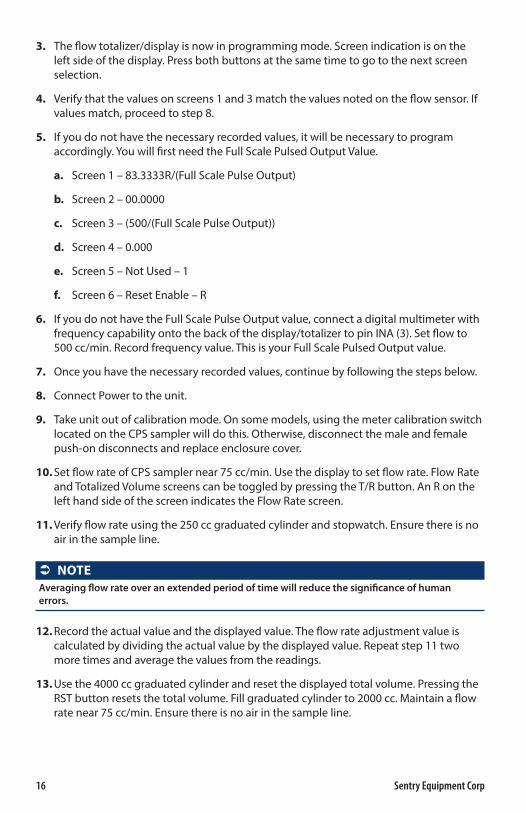
3. The flow totalizer/display is now in programming mode. Screen indication is on the left side of the display. Press both buttons at the same time to go to the next screen selection.
4. Verify that the values on screens 1 and 3 match the values noted on the flow sensor. If values match, proceed to step 8.
5. If you do not have the necessary recorded values, it will be necessary to program accordingly. You will first need the Full Scale Pulsed Output Value.
a. Screen 1 – 83.3333R/(Full Scale Pulse Output)
b. Screen 2 – 00.0000
c. Screen 3 – (500/(Full Scale Pulse Output))
d. Screen 4 – 0.000
e. Screen 5 – Not Used – 1
f. Screen 6 – Reset Enable – R
6. If you do not have the Full Scale Pulse Output value, connect a digital multimeter with frequency capability onto the back of the display/totalizer to pin INA (3). Set flow to 500 cc/min. Record frequency value. This is your Full Scale Pulsed Output value.
7. Once you have the necessary recorded values, continue by following the steps below.
8. Connect Power to the unit.
9. Take unit out of calibration mode. On some models, using the meter calibration switch located on the CPS sampler will do this. Otherwise, disconnect the male and female push-on disconnects and replace enclosure cover.
10. Set flow rate of CPS sampler near 75 cc/min. Use the display to set flow rate. Flow Rate and Totalized Volume screens can be toggled by pressing the T/R button. An R on the left hand side of the screen indicates the Flow Rate screen.
11. Verify flow rate using the 250 cc graduated cylinder and stopwatch. Ensure there is no air in the sample line.
 NOTEAveraging flow rate over an extended period of time will reduce the significance of human errors .
12. Record the actual value and the displayed value. The flow rate adjustment value is calculated by dividing the actual value by the displayed value. Repeat step 11 two more times and average the values from the readings.
13. Use the 4000 cc graduated cylinder and reset the displayed total volume. Pressing the RST button resets the total volume. Fill graduated cylinder to 2000 cc. Maintain a flow rate near 75 cc/min. Ensure there is no air in the sample line.
Sentry CPS Sampler 17
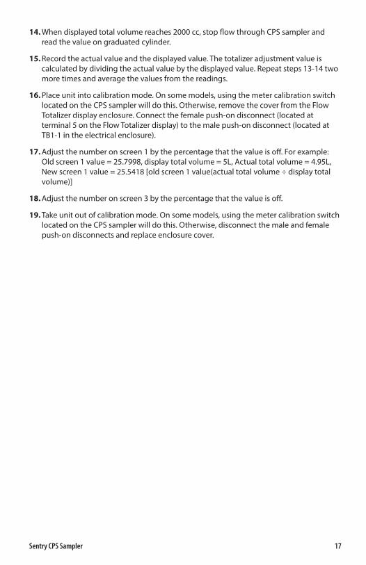
14. When displayed total volume reaches 2000 cc, stop flow through CPS sampler and read the value on graduated cylinder.
15. Record the actual value and the displayed value. The totalizer adjustment value is calculated by dividing the actual value by the displayed value. Repeat steps 13-14 two more times and average the values from the readings.
16. Place unit into calibration mode. On some models, using the meter calibration switch located on the CPS sampler will do this. Otherwise, remove the cover from the Flow Totalizer display enclosure. Connect the female push-on disconnect (located at terminal 5 on the Flow Totalizer display) to the male push-on disconnect (located at TB1-1 in the electrical enclosure).
17. Adjust the number on screen 1 by the percentage that the value is off. For example: Old screen 1 value = 25.7998, display total volume = 5L, Actual total volume = 4.95L, New screen 1 value = 25.5418 [old screen 1 value(actual total volume ÷ display total volume)]
18. Adjust the number on screen 3 by the percentage that the value is off.
19. Take unit out of calibration mode. On some models, using the meter calibration switch located on the CPS sampler will do this. Otherwise, disconnect the male and female push-on disconnects and replace enclosure cover.
18 Sentry Equipment Corp
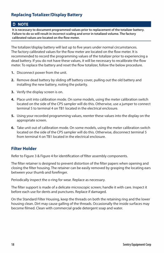
Replacing Totalizer/Display Battery
 NOTEIt is necessary to document programmed values prior to replacement of the totalizer battery . Failure to do so will result in incorrect scaling and error in totalized volume . The factory calibrated values are located on the flow meter .
The totalizer/display battery will last up to five years under normal circumstances. The factory calibrated values for the flow meter are located on the flow meter. It is recommended to record the programming values of the totalizer prior to experiencing a dead battery. If you do not have these values, it will be necessary to recalibrate the flow meter. To replace the battery and reset the flow totalizer, follow the below procedure.
1. Disconnect power from the unit.
2. Remove dead battery by sliding off battery cover, pulling out the old battery and installing the new battery, noting the polarity.
3. Verify the display screen is on.
4. Place unit into calibration mode. On some models, using the meter calibration switch located on the side of the CPS sampler will do this. Otherwise, use a jumper to connect terminal 5 to terminal 4 on TB1 located in the electrical enclosure.
5. Using your recorded programming values, reenter these values into the display on the appropriate screen.
6. Take unit out of calibration mode. On some models, using the meter calibration switch located on the side of the CPS sampler will do this. Otherwise, disconnect terminal 5 from terminal 4 on TB1 located in the electrical enclosure.
Filter Holder
Refer to Figure 3 & Figure 4 for identification of filter assembly components.
The filter retainer is designed to prevent distortion of the filter papers when opening and closing the filter housing. The retainer can be easily removed by grasping the locating ears between your thumb and forefinger.
Periodically inspect the o-ring for wear. Replace as necessary.
The filter support is made of a delicate microscopic screen; handle it with care. Inspect it before each use for dents and punctures. Replace if damaged.
On the Standard Filter Housing, keep the threads on both the retaining ring and the lower housing clean. Dirt may cause galling of the threads. Occasionally the inside surfaces may become filmed. Clean with commercial grade detergent soap and water.
Sentry CPS Sampler 19
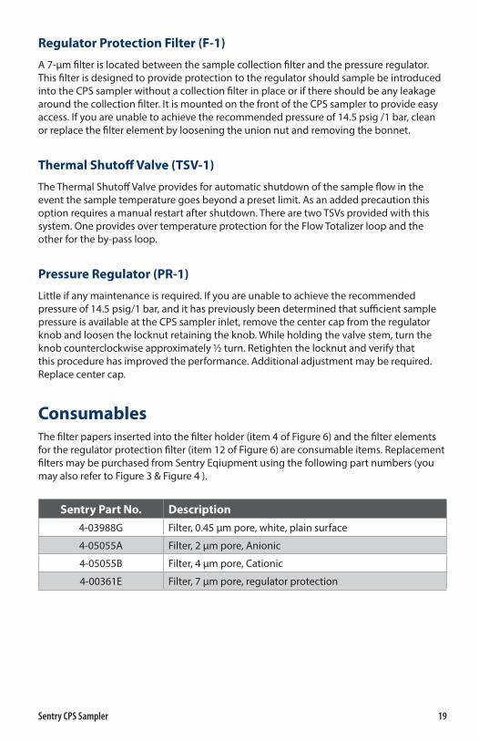
Regulator Protection Filter (F-1)
A 7-µm filter is located between the sample collection filter and the pressure regulator. This filter is designed to provide protection to the regulator should sample be introduced into the CPS sampler without a collection filter in place or if there should be any leakage around the collection filter. It is mounted on the front of the CPS sampler to provide easy access. If you are unable to achieve the recommended pressure of 14.5 psig /1 bar, clean or replace the filter element by loosening the union nut and removing the bonnet.
Thermal Shutoff Valve (TSV-1)
The Thermal Shutoff Valve provides for automatic shutdown of the sample flow in the event the sample temperature goes beyond a preset limit. As an added precaution this option requires a manual restart after shutdown. There are two TSVs provided with this system. One provides over temperature protection for the Flow Totalizer loop and the other for the by-pass loop.
Pressure Regulator (PR-1)
Little if any maintenance is required. If you are unable to achieve the recommended pressure of 14.5 psig/1 bar, and it has previously been determined that sufficient sample pressure is available at the CPS sampler inlet, remove the center cap from the regulator knob and loosen the locknut retaining the knob. While holding the valve stem, turn the knob counterclockwise approximately ½ turn. Retighten the locknut and verify that this procedure has improved the performance. Additional adjustment may be required. Replace center cap.
ConsumablesThe filter papers inserted into the filter holder (item 4 of Figure 6) and the filter elements for the regulator protection filter (item 12 of Figure 6) are consumable items. Replacement filters may be purchased from Sentry Eqiupment using the following part numbers (you may also refer to Figure 3 & Figure 4 ).
Sentry Part No. Description
4-03988G Filter, 0.45 µm pore, white, plain surface
4-05055A Filter, 2 µm pore, Anionic
4-05055B Filter, 4 µm pore, Cationic
4-00361E Filter, 7 µm pore, regulator protection
20 Sentry Equipment Corp
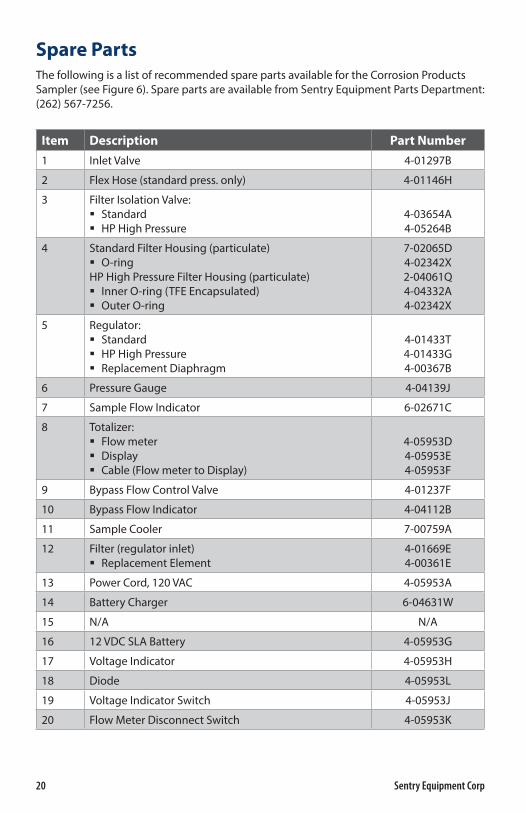
Spare PartsThe following is a list of recommended spare parts available for the Corrosion Products Sampler (see Figure 6). Spare parts are available from Sentry Equipment Parts Department: (262) 567-7256.
Item Description Part Number
1 Inlet Valve 4-01297B
2 Flex Hose (standard press. only) 4-01146H
3 Filter Isolation Valve: � Standard � HP High Pressure
4-03654A4-05264B
4 Standard Filter Housing (particulate) � O-ring
HP High Pressure Filter Housing (particulate) � Inner O-ring (TFE Encapsulated) � Outer O-ring
7-02065D4-02342X2-04061Q4-04332A4-02342X
5 Regulator: � Standard � HP High Pressure � Replacement Diaphragm
4-01433T4-01433G4-00367B
6 Pressure Gauge 4-04139J
7 Sample Flow Indicator 6-02671C
8 Totalizer: � Flow meter � Display � Cable (Flow meter to Display)
4-05953D4-05953E4-05953F
9 Bypass Flow Control Valve 4-01237F
10 Bypass Flow Indicator 4-04112B
11 Sample Cooler 7-00759A
12 Filter (regulator inlet) � Replacement Element
4-01669E4-00361E
13 Power Cord, 120 VAC 4-05953A
14 Battery Charger 6-04631W
15 N/A N/A
16 12 VDC SLA Battery 4-05953G
17 Voltage Indicator 4-05953H
18 Diode 4-05953L
19 Voltage Indicator Switch 4-05953J
20 Flow Meter Disconnect Switch 4-05953K
Sentry CPS Sampler 21
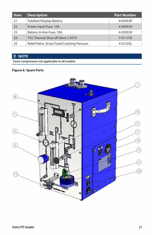
Item Description Part Number
21 Totalizer/Display Battery 4-05953P
22 Power Input Fuse, 10A 4-05953V
23 Battery In-line Fuse, 10A 4-05953X
24 TSV, Thermal Shut off Valve (120°F) 7-01137E
25 Relief Valve, 30 psi Fixed Cracking Pressure 4-01233L
 NOTESome components not applicable to all models .
Figure 6. Spare Parts

22 Sentry Equipment Corp
Standard WarrantySentry Equipment Corp (“Seller”) warrants products manufactured by it and supplied hereunder (“Products”) to be free from defects in workmanship and, to the extent materials are selected by Seller, to be free from defects in materials, in each case for a period as defi ned in the table below:
Brand Product Line Warranty PeriodSentry® � Steam & Water Sampling Products and Systems
� Solid & Powder Sampling Products and Systems � Gas Sampling Products and Systems � Liquid & Slurry Sampling Products and Systems � Pipeline Integrity Products
Eighteen months from date of shipment or twelve months from startup (whichever occurs fi rst)
Waters Equipment
Steam & Water Sampling Products and Systems Twelve months from date of shipment
To view the full warranty, go to www.sentry-equip.com/warranty.
Sentry CPS Sampler 23
Customer SupportWith proven sampling expertise since 1924, Sentry products and services provide business operations the critical insights to optimize process control and product quality. We deliver true representative sampling and analysis techniques to customers around the globe, empowering them to accurately monitor and measure processes for improved production effi ciency, output, and safety. Standing behind our commitments, we are determined to tackle any application, anywhere.
We know that running an effi cient operation isn’t easy. It requires thorough, careful analysis of controlled, real-time data achieved through reliable, accurate, and repeatable process monitoring and measuring. By eff ectively conditioning, sampling, and measuring gas, liquid, slurry, powder, solids, steam, or water within their production environments, our customers obtain the critical insights they need to control and optimize their processes.
Yet, controlling your processes also means reliable customer support throughout the life cycle of your equipment.
� Customer Service—General information, warranty claims, order management.
� Installation Service—For systems that require specialized expertise upon installation.
� Technical Support—Troubleshooting, training, and technical manuals.
� Field Service & Retrofi ts—When a problem needs immediate attention.
� Replacements Parts & Consumables—Order your replacement parts and consumables.
� Sentry ProShield Services—Select from four ProShield Guardian service plans providing diff erent levels of support to protect your large system investments with regularly scheduled maintenance.
To learn more, go to www.sentry-equip.com/support.

sentry-equip.com966 Blue Ribbon Circle North, Oconomowoc, WI 53066 U.S.A. | +1-262-567-7256 | [email protected]
Serving customers in more than 50 countries across six continents worldwide.