Embed Size (px)
Citation preview

Comitale National Inc.1683 B Winchester Road, Bensalem, PA 19020Phone: 215-244-9650Fax: 215-244-9679Email: [email protected]
Original Equipment Manufacturer ofCustom Packaged Terminal Air Conditioners andNational H.V.A.C. Parts Distributor
Inspection
Immediately upon receipt of equipment, inspect each carton for shipping damage. Before acceptingdelivery, make notations of damage on all copies of Bills of Lading and have all copies countersignedby delivering carrier.
File a claim with the carrier for any damage.
Installations/Disclaimer
When installing Comitale National, Inc. "Tru-Fit"TM Replacement Chassis, existing wall sleeves, exist-ing front panels, gasketing and insulation must be checked and/or replaced.
Comitale National, Inc. is not responsible for the existing design, execution and performance of theinstallation method or any of the accessory items used during installation such as: seals, caulking,weather proofing, supporting structures, attachment means, wall sleeves, front panels, louvers andframes supplied by others or existing.
Comitale National Inc.2
CNI
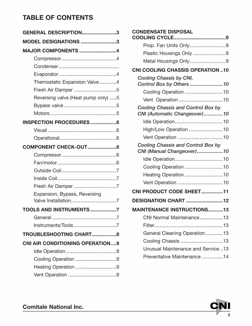
TABLE OF CONTENTS
GENERAL DESCRIPTION.........................3
MODEL DESIGNATIONS ..........................3
MAJOR COMPONENTS ...........................4
Compressor........................................4
Condenser ............................................
Evaporator ..........................................4
Themostatic Expansion Valve ............4
Fresh Air Damper ...............................5
Reversing valve (Heat pump only) .....5
Bypass valve ......................................5
Motors ................................................5
INSPECTION PROCEDURES...................6
Visual ..................................................6
Operational .........................................6
COMPONENT CHECK-OUT.....................6
Compressor........................................6
Fan/motor...........................................6
Outside Coil........................................7
Inside Coil...........................................7
Fresh Air Damper ...............................7
Expansion, Bypass, ReversingValve Installation.................................7
TOOLS AND INSTRUMENTS ...................7
General ...............................................7
Instruments/Tools ...............................7
TROUBLESHOOTING CHART..................8
CNI AIR CONDITIONING OPERATION....9
Idle Operation.....................................9
Cooling Operation ..............................9
Heating Operation ..............................9
Vent Operation ...................................9
CONDENSATE DISPOSAL COOLING CYCLE......................................9
Prop. Fan Units Only ..........................9
Plastic Housings Only ........................9
Metal Housings Only ..........................9
CNI COOLING CHASSIS OPERATION ..10
Cooling Chassis by CNI, Control Box by Others ........................10
Cooling Operation ............................10
Vent Operation ................................10
Cooling Chassis and Control Box by CNI (Automatic Changeover)..............10
Idle Operation...................................10
High/Low Operation .........................10
Vent Operation .................................10
Cooling Chassis and Control Box by CNI (Manual Changeover)...................10
Idle Operation...................................10
Cooling Operation ............................10
Heating Operation ............................10
Vent Operation .................................10
CNI PRODUCT CODE SHEET................11
DESIGNATION CHART ...........................12
MAINTENANCE INSTRUCTIONS...........13
CNI Normal Maintenance.................13
Filter..................................................13
General Cleaning Operation.............13
Cooling Chassis ...............................13
Unusual Maintenance and Service ..13
Preventative Maintenance................14

Comitale National Inc.3
CNI
GENERAL DESCRIPTIONCNI Cooling/Heat Pump chassis assembly is a hermetically sealed, closed circuit refrigerationsystem that may be installed or removed fromthe wall sleeve simply by sliding in or out of the cabinet and making or breaking plug-in connections.
Within the available models of units, there arevarious chassis assemblies that range in coolingcapacity from 7,000 BTUH to l8,000 BTUH.Assemblies are available for 115V/208V/230V, or277V single-phase, 60 Hertz operation.
The chassis assembly is a heavy duty, slide-inassembly with base pan, condensate disposal
MODEL DESIGNATIONSIn some models, the chassis identification label is attached to the front of the chassis. In othermodels, an identification label is attached to thecontrol box.
CNICOOLING CHASSISModel no. CCC0C094-D10AS208/230 volts 1 phase 60HzMin operating volts 197CHASSIS AMPS:FAN: 1.4/1.4 FLACOOLING: 6.0/5.6 FLA 23.8 LRAHEATING: FLA XXX LRA REFRIGERANT-22 33.75 ozsTEST PRESSURE 150 lo side 300 hi side USE TIME DELAY FUSE MAX AMPSSERIAL NO. 0210-0001W.O. NO. 13060
CNICOOLING CHASSISModel no. CMR0C094-000AS208/230 volts 1 phase 60HzMin operating volts 197CHASSIS AMPS:FAN: 1.5/1.7 FLACOOLING: 6.5/6.1 FLA 23.8 LRAREFRIGERANT-22 33.75 ozsTEST PRESSURE 150 lo side 300 hi side SERIAL NO. 0210-0001W.O. NO. 13060
CNIHEATPUMP CHASSISModel no. CCC0H094-E10AS208/230 volts 1 phase 60HzMin operating volts 197CHASSIS AMPS:FAN: 1.4/1.4 FLACOOLING: 6.0/5.6 FLA 23.8 LRAHEATING: 5.4/5.0 FLA 23.8 LRA aux heat FLA REFRIGERANT-22 33.75 ozsTEST PRESSURE 300 lo side 300 hi side USE TIME DELAY FUSE MAX AMPSSERIAL NO. 0210-0001W.O. NO. 13060
CNIHEATPUMP CHASSISModel no. CMR0H094-E10AS208/230 volts 1 phase 60HzMin operating volts 197CHASSIS AMPS:FAN: 1.5/1.7 FLACOOLING: 6.5/6.1 FLA 23.8 LRAHEATING: 5.9/5.5 FLA 23.8 LRA REFRIGERANT-22 23.375 ozsTEST PRESSURE 300 lo side 300 hi side USE TIME DELAY FUSE MAX AMPSSERIAL NO. 0210-0001W.O. NO. 13060
system, hermetically sealed refrigerant circuitand fresh air damper with filter.
In the cooling mode the condensate disposalsystem provides fast and 100% effectiveremoval of condensate under all cooling operat-ing conditions. Condensate from the cooling coilis drained from the drain pan into a tube in thecondenser air stream where it is atomized andevaporated as it passes across the hot con-denser coil
Chassis is fully insulated and is furnished with aquick disconnect plug to connect to power.
The identification label identifies the unit modelnumber, voltage phase, full load amperes, typeof refrigerant, and other pertinent data.
Refer to Page 11and 12 for model codes andapplications.
Comitale National Inc.4
CNI
MAJOR COMPONENTSCompressorChassis refrigerant compressor is a direct-connected motor compressor assemblyenclosed within a steel housing and designed topump low pressure refrigerant gas to a higherpressure.
This compressor is of the low pressure shell orhousing type. This means that the compressorhousing interior is subjected to suction pressurecreated by the stroke of the piston. This point isemphasized in order to stress the hazard ofintroducing high pressure gas into the compres-sor shell at pressures above 150 PSIG.
The motor within the compressor housing isdesigned to operate within a refrigerant gasatmosphere. It is of the Permanent SplitCapacitor type (PSC). A run capacitor is in serieswith the start winding. Both run capacitor andstart winding remain in the circuit during startand after the motor is up to speed. No startcapacitor or relay is necessary.
CondenserCondensers for all models are constructed ofcopper tubes expanded into aluminum fins. Endplates are of 0.050 aluminum. Coils are either 2or 4 rows deep and vary in length according tocapacity requirements.
EvaporatorEvaporators for all models are constructed ofcopper tubes expanded into aluminum fins. Endplates are of 0.050 aluminum. Coils are either 23, or 4 rows deep and vary in length accordingto capacity requirements.
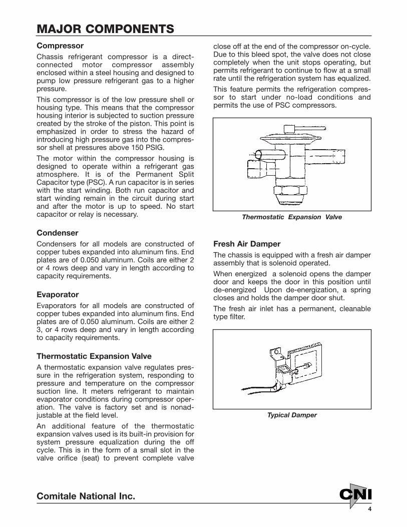
Thermostatic Expansion ValveA thermostatic expansion valve regulates pres-sure in the refrigeration system, responding topressure and temperature on the compressorsuction line. It meters refrigerant to maintainevaporator conditions during compressor oper-ation. The valve is factory set and is nonad-justable at the field level.
An additional feature of the thermostatic expansion valves used is its built-in provision forsystem pressure equalization during the offcycle. This is in the form of a small slot in thevalve orifice (seat) to prevent complete valve
close off at the end of the compressor on-cycle.Due to this bleed spot, the valve does not closecompletely when the unit stops operating, butpermits refrigerant to continue to flow at a smallrate until the refrigeration system has equalized.
This feature permits the refrigeration compres-sor to start under no-load conditions and permits the use of PSC compressors.
Thermostatic Expansion Valve
Fresh Air DamperThe chassis is equipped with a fresh air damperassembly that is solenoid operated.
When energized a solenoid opens the damperdoor and keeps the door in this position until de-energized Upon de-energization, a springcloses and holds the damper door shut.
The fresh air inlet has a permanent, cleanabletype filter.
Typical Damper

Comitale National Inc.5
CNI
Reversing Valve (Heat pump only)Heating Cycle
With the 4 way solenoid reversing valve de-ener-gized the system is on the heating cycle with thedischarge and suction gases flowing thru thereversing valve ports making the indoor coil thecondenser and the outdoor coil the evaporator.
Cooling Cycle
When the 4 way solenoid reversing valve is ener-gized the system changes over to the coolingcycle with the discharge and suction gasesfIowing thru the reversing valve ports making theoutdoor coil the condenser and the indoor coilthe evaporator.
Reversing valve (Heat pump only)
Bypass ValveThis valve will bypass hot discharge gas into theinside coil if the inside coil pressure falls below apre-set pressure.This valve oper-ates only in theair conditioningmode to preventinside coil freezeup during lightload conditions.This valve is non-adjustable at thefield level.
MotorsRugged PSC motors of the single and/or doubleshaft design are used in all refrigeration chassis.
Single Shaft (Typical)
Double Shaft (Typical)
MAJOR COMPONENTS Continued
Bypass Valve

Comitale National Inc.6
CNI
Visuala. Check all wires for signs of wear chafing or
breaks.
b. Check electrical connections to be sure theyare secure.
c. Fan motor and compressor capacitors mustbe mounted securely, have tight connectionsand not be blown out as far as a visualinspection can determine.
d. Remove compressor terminal box cover andcheck connections to all terminals to makesure they are all intact and secure.
Operationala. Check supply voltage against unit nameplate.
b. Install and electrically connect the chassis tothe proper power.
c. Operate chassis to determine the exactnature of the defect.
1. If unit apparently operates satisfactorily -refer to component check out section andperform cleaning and lubrication proce-dures. Return unit to operation.
2. If unit fails to operate, or operates improp-erly, it will be necessary to refer to the"Troubleshooting" section to check outcomponents individually.
INSPECTION PROCEDURES
COMPONENT CHECK-OUT
CompressorRun Capacitors
1. Disconnect the run capacitor from the sys-tem wiring.
2. Using a capacitor checker, connect thecapacitor to the checker and check capacitorper instructions supplied with instrument.
3. Connect an ohmmeter between the capaci-tor case and both capacitor terminals (one ata time). Continuity indicates a groundedcapacitor. Replace capacitor.
Motor Windings
1. Disconnect all leads to the compressormotor terminals.
2. Identify Start (S), Common (C), and Run (R)terminals of compressor.
3. Using an ohmmeter, check continuity acrossthe following terminals combinations:
a. "C" to "S" - If no continuity, Start windingis open. If zero ohms, Start winding is
shorted.
b. "C" to "R" - If no continuity, Run winding is open. If zero ohms, Run winding isshorted.
c. "C" to shell of compressor - If continuity,motor is grounded. if zero ohms, motor isshorted.
Run Test (Compressor in cooling chassis)
1. Apply power to start the compressor.
2. Observe amperage draw. If excessive orsame as locked rotor rating as shown oncompressor serial plate, compressor must bereplaced.
3. Determine if compressor sound level is nor-mal or excessive. If compressor sound levelis abnormal, compressor must be replaced.
4. If compressor will not run, it is stuck andmust be replaced.
Mounting
1. Inspect the compressor mounts to be surethey are free to move and rubber parts havenot deteriorated.
2. Inspect studs for breaks or damage.
Fan/Motora. Apply power to fan motor through its run
capacitor. If motor fails to run, check:
1. Power wiring for open circuit.
2. Continuity of fan motor windings with ohmmeter.
3. Motor wire for loose or bent connectors.
4. Running capacitor with capacitor checker.

Comitale National Inc.7
CNI
b. Check amperage draw of fan motor againstvalue listed on nameplate. If amperage isexcessive, replace motor.
c. Check orientation of fan motor. Air openingsof motor must be facing down to preventwater from remaining in motor. Oilers mustbe facing up to prevent oil from running out.
d. Check tightness of fan motor capacitor strap.
e. Observe blower wheel to see that it issecurely fastened to motor shaft and rotatesfreely within the scroll without rubbing orbinding.
f. Oil motor with a few drops of oil in each oiler.
Outside Coila. Wash outside coil with a mild soap and water
solution, using a soft brush. Flush clean.
b. Straighten fins with fin comb
c. Inspect coils for damage, repair damagedareas or replace coil.
d. Clean and flush drain pan located under out-side coil.
Inside Coila. Wash inside coil with a mild soap and water
solution, using a soft brush. Flush clean.
b. Straighten fins with fin comb.
c. Inspect coils for damage, repair damagedareas or replace coil.
Fresh air dampera. Disconnect damper assembly linkage and
the vent solenoid.
b. Clean and lubricate damper linkage, using alight grease.
c. Manually open damper door one inch Ifwhen released the door does not close, doorspring must be replaced.
d. Check damper to make sure that the weath-er seal is secure.
e. Reconnect damper assembly linkage andenergize and de-energize the assembly withthe Vent Switch.
f. If damper door does not open, solenoidreplacement is required.
g. Inspect and clean or replace fresh air filter.
Expansion, Bypass, Reversing ValveInstallationa. Recover system refrigerant.
b. Un-braze valve from system tubing. Purgesystem with dry nitrogen during the un-braz-ing operation.
c. Wrap the body of the new valve with a wet ragduring the operation.
GeneralIn addition to general mechanics and refrigera-tion tools, there are some required instrumentswhich are necessary to perform the test andrepair procedures outlined in this manual.
1. Shop voltage requirements:
115V, single phase, 60 Hertz
208V, single phase, 60 Hertz
230V, single phase, 60 Hertz
277V, single phase, 60 Hertz
TOOLS AND INSTRUMENTS
Instruments/Tools1. Temperature recorder
2. Ohmmeter
3. Volt meter
4. Capacitor tester
5. Fin comb
COMPONENT CHECK-OUT Continued
d. Remove drain tube and thoroughly flush draintube. Dry drain tube and inspect for breaks ordeterioration. Replace, if necessary.
e. Clean and flush drain pan located underinside coil.
Comitale National Inc.8
CNI
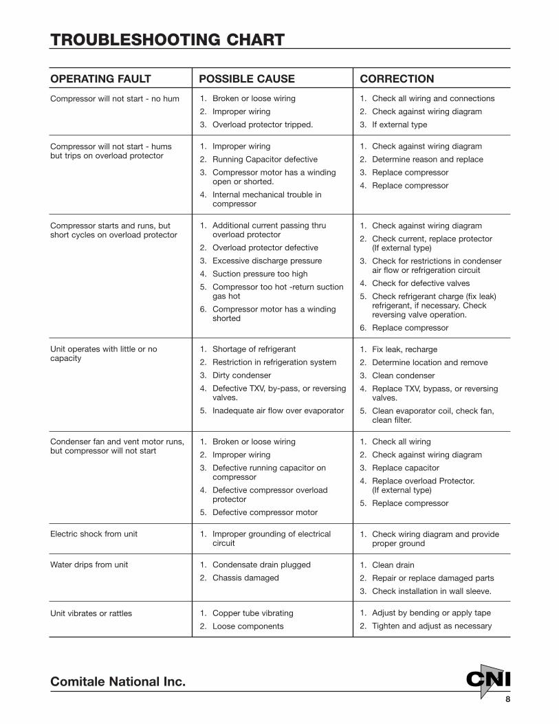
TROUBLESHOOTING CHART
OPERATING FAULT
Compressor will not start - no hum
Compressor will not start - humsbut trips on overload protector
Compressor starts and runs, butshort cycles on overload protector
Unit operates with little or no capacity
Condenser fan and vent motor runs,but compressor will not start
Electric shock from unit
Water drips from unit
Unit vibrates or rattles
POSSIBLE CAUSE
1. Broken or loose wiring
2. Improper wiring
3. Overload protector tripped.
1. Improper wiring
2. Running Capacitor defective
3. Compressor motor has a windingopen or shorted.
4. Internal mechanical trouble in compressor
1. Additional current passing thruoverload protector
2. Overload protector defective
3. Excessive discharge pressure
4. Suction pressure too high
5. Compressor too hot -return suctiongas hot
6. Compressor motor has a windingshorted
1. Shortage of refrigerant
2. Restriction in refrigeration system
3. Dirty condenser
4. Defective TXV, by-pass, or reversingvalves.
5. Inadequate air flow over evaporator
1. Broken or loose wiring
2. Improper wiring
3. Defective running capacitor oncompressor
4. Defective compressor overloadprotector
5. Defective compressor motor
1. Improper grounding of electrical circuit
1. Condensate drain plugged
2. Chassis damaged
1. Copper tube vibrating
2. Loose components
CORRECTION
1. Check all wiring and connections
2. Check against wiring diagram
3. If external type
1. Check against wiring diagram
2. Determine reason and replace
3. Replace compressor
4. Replace compressor
1. Check against wiring diagram
2. Check current, replace protector(If external type)
3. Check for restrictions in condenserair flow or refrigeration circuit
4. Check for defective valves
5. Check refrigerant charge (fix leak)refrigerant, if necessary. Checkreversing valve operation.
6. Replace compressor
1. Fix leak, recharge
2. Determine location and remove
3. Clean condenser
4. Replace TXV, bypass, or reversingvalves.
5. Clean evaporator coil, check fan,clean filter.
1. Check all wiring
2. Check against wiring diagram
3. Replace capacitor
4. Replace overload Protector. (If external type)
5. Replace compressor
1. Check wiring diagram and provideproper ground
1. Clean drain
2. Repair or replace damaged parts
3. Check installation in wall sleeve.
1. Adjust by bending or apply tape
2. Tighten and adjust as necessary

Comitale National Inc.9
CNI
CNI AIR CONDITIONING OPERATIONIdle OperationDepressing, the idle button terminates all func-tions except for compressor off-cycle heat.
Cooling OperationDepress cool button. This energizes the revers-ing valve.
Select Hi-Lo fan speed.
Set room thermostat to satisfy desired roomtemperature
Air conditioner will bring room to desired tem-perature and continue to cycle compressor uponroom thermostat demand.
Heating OperationDepress heat button.
Select Hi-Lo fan speed.
Set room thermostat to satisfy desired roomtemperature.
Compressor in heating mode will bring room todesired temperature and continue to cycle com-pressor upon room thermostat demand.
Metal HousingsThe condensate from the inside coil is thrown uponto the hot outside coil and is re-evaporated bymeans of slit in the fan housing that draws waterfrom the base pan and discharges it into the out-side fan air stream.
If the compressor heating, mode does not satis-fy heating load, the second stage of auxiliaryheat will be automatically engaged when theroom temperature falls approximately 3 degreesbelow room thermostat setting.
When outside air temperature falls belowapproximately 35 degrees F, the compressor willbe automatically locked out. The locking out ofthe compressor will automatically switch roomthermostat control to first stage auxiliary heat.This stage of auxiliary heat will cycle on and offbased on room thermostat demand.
When outside air temperature rises back toapproximately 45 degrees F the compressorheat pump cycle resumes operation.
Vent OperationWith the vent switch in the on position, the ventdamper opens and outdoor air is directed thruthe unit into the room after selecting Hi-Lo fanspeed.
The vent damper closes automatically wheneither the vent switch is turned off or the idlebutton is depressed.
CONDENSATE DISPOSAL COOLING CYCLE

Comitale National Inc.10
CNI
CNI COOLING CHASSIS OPERATIONCOOLING CHASSIS BY CNI, CONTROL BOX BY OTHERS
Cooling OperationUpon call for cooling from the existing controlbox the compressor and outside fan motor willbe energized and cool air will be supplied to theconditioned space for as long as the control boxcontinues to call for cooling.
Vent OperationUpon call for ventilation from the existing controlbox, the vent damper will open to introduce out-side air to the conditioned space. Separate out-side motor units. Depending on control boxwiring, the outside fan may run.
(AUTOMATIC CHANGEOVER)
Idle OperationDepressing idle bottom terminates all functionsof the unit.
High/Low OperationDepressing the high or low button selects theindoor fan speed and energizes the system forheating or cooling, depending on room thermo-stat set point versus room temperature.
Vent OperationCombination Inside/Outside Motor
With the vent switch in the on position, the ventwill open to introduce outside air to the condi-tioned space as long as the Hi or Lo buttons aredepressed.
COOLING CHASSIS AND CONTROLBOX BY CNI
(MANUAL CHANGEOVER)
Idle OperationDepressing the idle button terminates all func-tions of the unit.
Cooling OperationDepress cool button to activate the coolingmode and select either hi or lo fan speed. Thecompressor will operate upon demand of theroom thermostat.
Heating OperationDepress heat button to activate the heatingmode and select either hi or lo fan speed. Theheating section (electric or hydronic) will operateupon demand of the room thermostat.
Vent OperationCombination Inside/Outside Motor
With the vent switch in the on position the ventwill open to introduce outside air to the condi-tioned space as long as the heat or cool buttonsare depressed.
Vent OperationSeparate Motor
Operation is the same as above except that theoutside motor will also be energized with thevent switch.
COOLING CHASSIS AND CONTROLBOX BY CNI
Comitale National, Inc.
Comitale National Inc.11
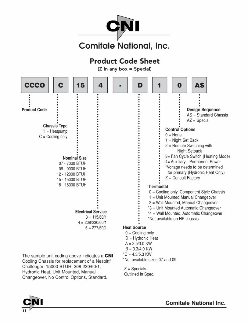
CNI
CNI
Product Code
Chassis TypeH = Heatpump
C = Cooling only
Nominal Size07 - 7000 BTUH09 - 9000 BTUH
12 - 12000 BTUH15 - 15000 BTUH18 - 18000 BTUH
Electrical Service3 = 115/60/1
4 = 208/230/60/15 = 277/60/1
Design SequenceAS = Standard ChassisAZ = Special
Control Options0 = None1 = Night Set Back2 = Remote Switching with
Night Setback3= Fan Cycle Switch (Heating Mode)4= Auxiliary - Permanent Power *Voltage needs to be determined
for primary (Hydronic Heat Only)Z = Consult Factory
Thermostat0 = Cooling only, Component Style Chassis1 = Unit Mounted Manual Changeover2 = Wall Mounted, Manual Changeover
*3 = Unit Mounted Automatic Changeover*4 = Wall Mounted, Automatic Changeover*Not available on HP chassis
Heat Source0 = Cooling onlyD = Hydronic HeatA = 2.5/3.0 KWB = 3.3/4.0 KW
*C = 4.3/5.3 KW*Not available sizes 07 and 09
Z = SpecialsOutlined in Spec.
The sample unit coding above indicates a CNICooling Chassis for replacement of a Nesbitt®
Challenger; 15000 BTUH, 208-230/60/1,Hydronic Heat, Unit Mounted, ManualChangeover, No Control Options, Standard.
Product Code Sheet(Z in any box = Special)
CCCO C 15 4 - D 1 0 AS
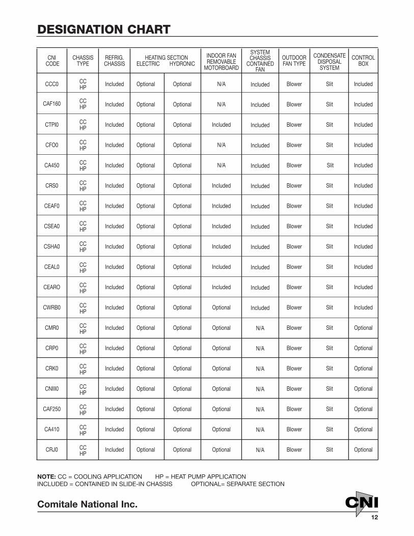
CNICODE
CCC0
CAF160
CTPI0
CFO0
CA450
CRS0
CEAF0
CSEA0
CSHA0
CEAL0
CEARO
CWRB0
CMR0
CRP0
CRK0
CNIII0
CAF250
CA410
CRJ0
CHASSISTYPE
CCHP
CCHP
CCHP
CCHP
CCHP
CCHP
CCHP
CCHP
CCHP
CCHP
CCHP
CCHP
CCHP
CCHP
CCHP
CCHP
CCHP
CCHP
CCHP
REFRIG.CHASSIS
Included
Included
Included
Included
Included
Included
Included
Included
Included
Included
Included
Included
Included
Included
Included
Included
Included
Included
Included
HEATING SECTIONELECTRIC HYDRONIC
Optional Optional
Optional Optional
Optional Optional
Optional Optional
Optional Optional
Optional Optional
Optional Optional
Optional Optional
Optional Optional
Optional Optional
Optional Optional
Optional Optional
Optional Optional
Optional Optional
Optional Optional
Optional Optional
Optional Optional
Optional Optional
Optional Optional
INDOOR FANREMOVABLE
MOTORBOARD
N/A
N/A
Included
N/A
N/A
Included
Included
Included
Included
Included
Included
Optional
Optional
Optional
Optional
Optional
Optional
Optional
Optional
SYSTEMCHASSIS
CONTAINED FAN
Included
Included
Included
Included
Included
Included
Included
Included
Included
Included
Included
Included
N/A
N/A
N/A
N/A
N/A
N/A
N/A
OUTDOORFAN TYPE
Blower
Blower
Blower
Blower
Blower
Blower
Blower
Blower
Blower
Blower
Blower
Blower
Blower
Blower
Blower
Blower
Blower
Blower
Blower
CONDENSATEDISPOSALSYSTEM
Slit
Slit
Slit
Slit
Slit
Slit
Slit
Slit
Slit
Slit
Slit
Slit
Slit
Slit
Slit
Slit
Slit
Slit
Slit
CONTROLBOX
Included
Included
Included
Included
Included
Included
Included
Included
Included
Included
Included
Included
Optional
Optional
Optional
Optional
Optional
Optional
Optional
NOTE: CC = COOLING APPLICATION HP = HEAT PUMP APPLICATION INCLUDED = CONTAINED IN SLIDE-IN CHASSIS OPTIONAL= SEPARATE SECTION
Comitale National Inc.12
CNI
DESIGNATION CHART
13
CNI
MAINTENANCE INSTRUCTIONSCNI Normal MaintenanceThis is a simple procedure and should be per-formed on a scheduled basis by normal mainte-nance personnel.
FilterClean or replace air filter regularly (Every sixmonths or as required)
Filter change or clean with soap and water.
*Important Do not run unit without filter.
General Cleaning Operation(Once a year or as required)
Should be performed on a regular basis of oncea year. Frequency depends on local atmospher-ic conditions and application. Complete clean-ing should not exceed three years.
1. Remove chassis from wall sleeve.
2. Short out all capacitors, then disconnectcapacitor wires.
3. Chassis should be taken to work area to per-form clean-up operations. (See instructionsfollowing step No. 10)
4. Vacuum and thoroughly clean piping com-partments, inside of cabinet and wall sleeve.
5. Inspect wiring for tight connections in electri-cal compartments.
6. Inspect pipes for leaks.
7. Clean outdoor grille with water and milddetergent, using soft brush.
8. Clean bottom of wall sleeve.
9. Replace or repair insulation and rubber sealson cooling chassis and room cabinet whererequired (with same type).
Cooling Chassis10. Remove condenser unit top cover from cool-
ing chassis.
11. Every three years or 12,000 running hourslubricate the bearing of the condenser andevaporator motor with SAE-20 or commer-cial grade electric motor oil. Use approxi-mately 1 teaspoon oil. DO NOT OVERFILL!
12. Wash evaporator and condenser coils withevap power “C" coil cleaner.
13. Remove drain tube and flush both sides.
14. Clean and flush drain pan at both ends.
15. Dry all parts of equipment thoroughly.
16. Replace metal panels and tighten screws.
17. When reconnecting capacitor follow diagramon chassis.
18. If damper is furnished, clean and lightlygrease linkage.
19. Test-run cooling chassis before returningunit.
*Important: Do not stop or start unit on cool-ing more than once within 3 minute cycle.
Unusual Maintenance and ServiceUnusual maintenance is required when equip-ment does not function properly. If electricalservice is performed, turn power off at unit andsource, which is located at buildings centralcontrol panel. This type of maintenance whichincludes refrigeration service, should only beperformed by factory authorized service agen-cies or trained refrigeration mechanics.
First, check the following before calling:
1. Check switches and fuses or circuit breakerto make sure power is on.
2. Make sure all plugs are properly seated.
3. See nameplate for required voltage to unitand check voltage at source.
4. Be sure filter is clean.
5. Check proper control sequence and opera-tion procedure.
Comitale National Inc.

Comitale National Inc.14
CNI
Preventative MaintenanceA scheduled and properly executed maintenance program will minimize and possibly prevent specialmaintenance. It is not unusual for the C.N.I. "Tru-Fit" to have component replacement rate of less thanone percent to facilitate maintenance and insure that each unit will be available for operation, maintaina small stock of replacement components.
For example: Based on 100 units, stock the following:
• One complete cooling chassis per unit size.
• One evaporator and condenser motor and fan assembly per unit size.
• 100 pcs. Replacement filters - depending on usage.
• 10 pcs. Cleanable filters - depending on usage.

Comitale National, Inc.1683 B Winchester Road • Bensalem, PA 19020
215-244-9650 • FAX 215-244-9679 email:[email protected] Equipment Manufacturer of Custom Package Terminal Air Conditioners and National H.V.A.C. Parts Distributor.