Embed Size (px)
Citation preview
To ensure that the steelmaking shop and other shops at the factory of the Mechel Company have adequate supplies
of carburizer, the department that recycles sludge from sintering operations has organized a section to make this material.
The main piece of machinery used in the section is a rotary dryer, and the raw material is coke fines (<10 mm) obtained after
coke has been screened.
The process of making the carburizer involves drying coke fines with a moisture content of 15–40%, which yields
a material with a moisture content no greater than 1.5% and a carbon content of at least 78%.
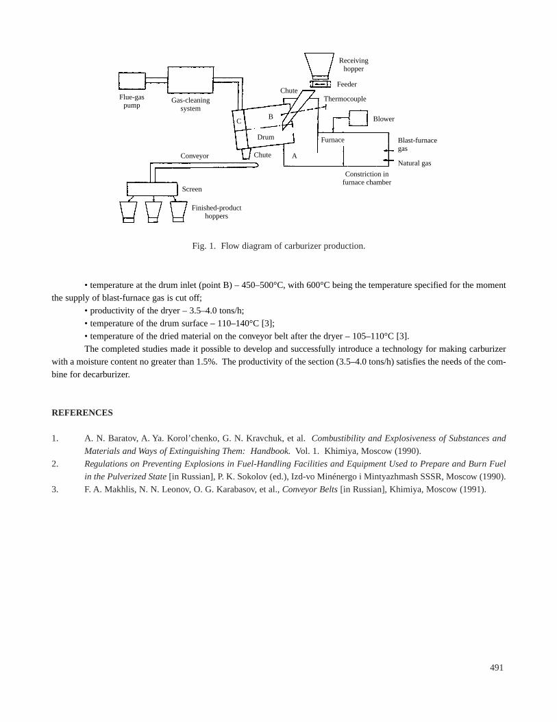
Figure 1 presents a flow diagram of the process. The furnace is equipped with two burners which use blast-furnace
gas and two continuously operating ignition chambers which use natural gas. The length of the body of the drum of the dryer
is 16,000 mm, the angle of inclination is 2°, and the speed of rotation is 2 min–1. The rear part of the drum includes vane-type
heat exchangers, beginning with seven rows of 18 vanes each. The dried material is separated into three fractions: 0–2, 2–8,
and 8–10 mm.
Test dryings of coke fines showed that the temperature of the heat-transfer agent ahead of the drum (point A in
Fig. 1) – which ranges up to 400°C – was too low; the moisture content of the dried material fluctuated widely – from 1.6
to 7.4%, with an average of 3.4%. The temperature at point A remained nearly constant, regardless of the amount of raw
material in the drum. The temperature of the outlet of the drum (point C) – which determines the quality of the drying –
ranged from 90 to 145°C. Under these conditions, the temperature of the dried material after the drum was within the range
60–70°C.
To improve heat exchange between the coke fines and the heat-transfer agent, we installed additional vane heat
exchangers along the entire length of the drum. This modification reduced the moisture content of the dried material by
roughly 30%.
The results of the tests showed a need for the following measures: conduct the drying process so that the temper-
ature at point C is controlled automatically; move the thermocouple from point A to point B, its function having been
changed from one of control to one of monitoring and protection; cut off the supply of blast-furnace gas when the temper-
ature at point B reaches 600°C [2]. Implementation of these changes made it possible to keep the fluctuations of the tem-
perature at point C to ±10°C.
A blower was installed to provide additional air in order to equalize the temperature along the drum during the peri-
od between emptying and filling of the hopper and to increase the volume of heat-transfer agent in the furnace.
During initial tests, we devised a safe drying technology which ensures that the quality specified for the carburizer
will be consistently achieved:
• temperature at the outlet of the drum at point C – 200±10°C;
• discharge of natural gas – 2400–3200 m3/h;
Metallurgist, Vol. 45, Nos. 11–12, 2001
ORGANIZING THE PRODUCTION OF A CARBURIZER
AT THE CHELYABINSK METALLURGICAL COMBINE
A. V. Vereshchagin, S. V. Dvoryashin,V. E. Korolev, I. V. Zueva,and S. V. Sheveleva
UDC 669.18.62
Open Joint-Stock Company Mechel. Translated from Metallurg, No. 12, p. 40, December, 2001.
0026-0894/01/1112-0490$25.00 ©2001 Plenum Publishing Corporation490
• temperature at the drum inlet (point B) – 450–500°C, with 600°C being the temperature specified for the moment
the supply of blast-furnace gas is cut off;
• productivity of the dryer – 3.5–4.0 tons/h;
• temperature of the drum surface – 110–140°C [3];
• temperature of the dried material on the conveyor belt after the dryer – 105–110°C [3].
The completed studies made it possible to develop and successfully introduce a technology for making carburizer
with a moisture content no greater than 1.5%. The productivity of the section (3.5–4.0 tons/h) satisfies the needs of the com-
bine for decarburizer.
REFERENCES
1. A. N. Baratov, A. Ya. Korol’chenko, G. N. Kravchuk, et al. Combustibility and Explosiveness of Substances and
Materials and Ways of Extinguishing Them: Handbook.Vol. 1. Khimiya,Moscow (1990).
2. Regulations on Preventing Explosions in Fuel-Handling Facilities and Equipment Used to Prepare and Burn Fuel
in the Pulverized State [in Russian],P. K. Sokolov (ed.), Izd-vo Minénergo i Mintyazhmash SSSR,Moscow (1990).
3. F. A. Makhlis,N. N. Leonov, O. G. Karabasov, et al.,Conveyor Belts[in Russian],Khimiya,Moscow (1991).
491
Flue-gaspump
Gas-cleaningsystem
Chute
Chute
Receivinghopper
Feeder
Thermocouple
Blower
Furnace Blast-furnacegas
Natural gas
Constriction infurnace chamber
Drum
Conveyor
Screen
Finished-producthoppers
CB
A
Fig. 1. Flow diagram of carburizer production.