Embed Size (px)
Citation preview

®ORBIT
®ORBIT Technical Reference Datafor Valves and Actuators
P R O C E S S V A L V E S

P R O C E S S V A L V E S
CT-ORB-TEC/REF/207/07 NP-2M 1®
ORBIT
P R O C E S S V A L V E S
TABLE OF CONTENTS
ORBIT TECHNICAL REFERENCE DATA FOR VALVES AND ACTUATORS
Standard Features 2
Ordering Information 3
The ORBIT Principal 4
One Piece Stem, Enclosed Bonnet Valves Details and Materials 6
Two Piece Stem, Enclosed Bonnet Valves Details and Materials 8
One Piece Stem, O.S. & Y. Bonnet Valves Details and Materials 10
Two Piece Stem, O.S. & Y. Bonnet Valves Details and Materials 12
End Flange Bolting Dimensions 14
Seat and Stem Packing Selection 16
Markings 17
Pressure Testing and Pressure Drop Formulas 18
Actuator Figure Numbers 19
TRADEMARK INFORMATION 21
ADDITIONAL ORBIT INFORMATION
The Company and it’s Products
Dimensional Data, Valves and Actuators
Automated Valve Packages
Standard Instrumentation Packages
Installation and Maintenance
Parts List and Ordering Instructions
P R O C E S S V A L V E S
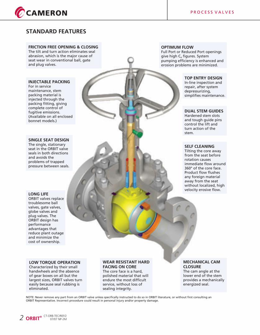
MECHANICAL CAM CLOSUREThe cam angle at the lower end of the stem provides a mechanically energized seal.
LONG LIFEORBIT valves replace troublesome ball valves, gate valves, globe valves and plug valves. The ORBIT design has performance advantages that reduce plant outage and minimize the cost of ownership.
SINGLE SEAT DESIGNThe single, stationary seat in the ORBIT valve seals in both directions and avoids the problems of trapped pressure between seals.
OPTIMUM FLOWFull Port or Reduced Port openings give high C figures. System V
pumping efficiency is enhanced and erosion problems are minimized.
FRICTION FREE OPENING & CLOSINGThe tilt and turn action eliminates seal abrasion, which is the major cause of seat wear in conventional ball, gate and plug valves.
DUAL STEM GUIDESHardened stem slots and tough guide pins control the lift and turn action of the stem.
TOP ENTRY DESIGNIn-line inspection and repair, after system depressurizing, simplifies maintenance.
WEAR RESISTANT HARD FACING ON COREThe core face is a hard, polished material that will endure the most difficult service, without loss of sealing integrity.
SELF CLEANINGTilting the core away from the seat before rotation causes immediate flow around 360° of the core face. Product flow flushes any foreign material away from the seat without localized, high velocity erosive flow.
INJECTABLE PACKINGFor in service maintenance, stem packing material is injected through the packing fitting, giving complete control of fugitive emissions.(Available on all enclosed bonnet models.)
2
NOTE: Never remove any part from an ORBIT valve unless specifically instructed to do so in ORBIT literature, or without first consulting anORBIT Representative. Incorrect procedure could result in personal injury and/or property damage.
LOW TORQUE OPERATIONCharacterized by their small handwheels and the absence of gear boxes on all but the largest sizes, ORBIT valves turn easily because seal rubbing is eliminated.
CT-ORB-TEC/REF/207/07 NP-2M
®ORBIT
STANDARD FEATURES
3®ORBIT
P R O C E S S V A L V E S
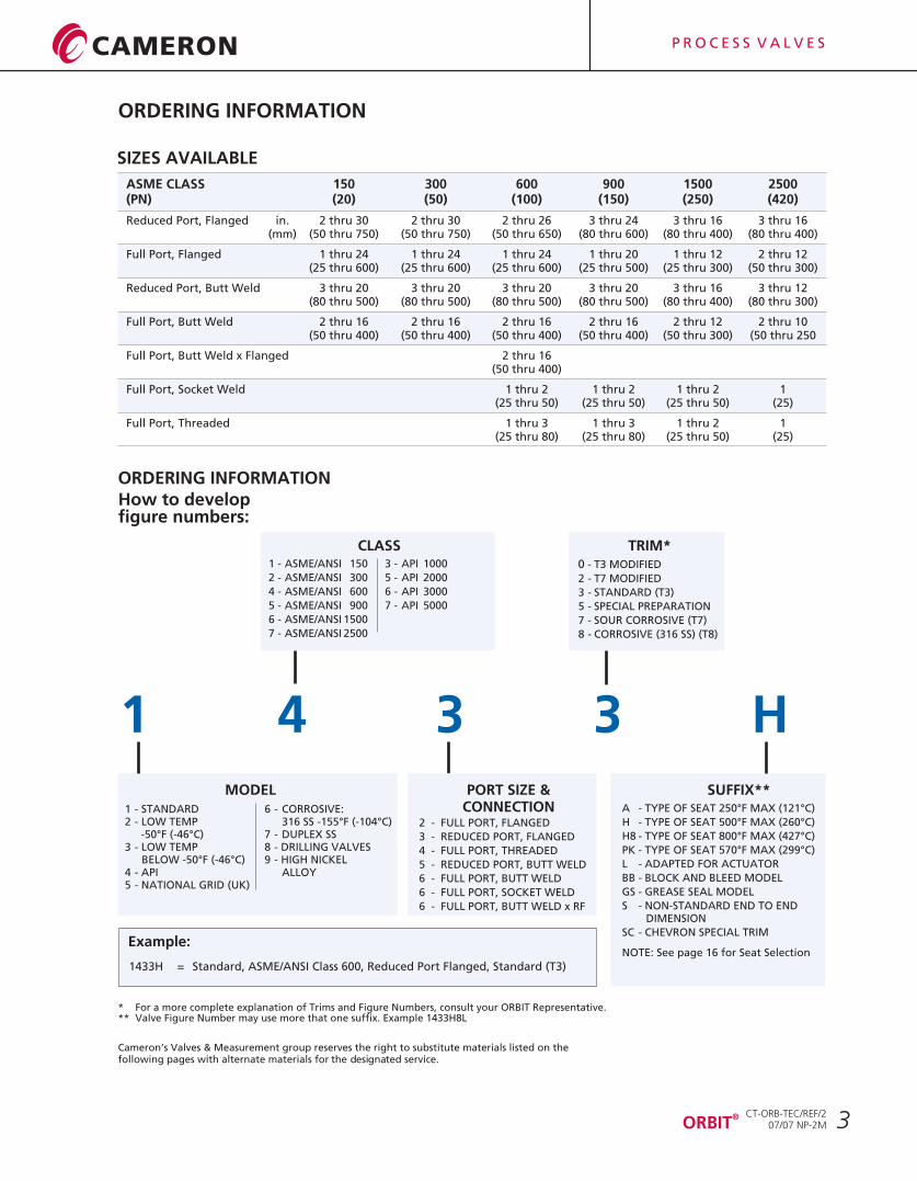
ORDERING INFORMATION
1433H = Standard, ASME/ANSI Class 600, Reduced Port Flanged, Standard (T3)
1 4 3 3 H
How to developfigure numbers:
Example:
* For a more complete explanation of Trims and Figure Numbers, consult your ORBIT Representative.** Valve Figure Number may use more that one suffix. Example 1433H8L
Cameron’s Valves & Measurement group reserves the right to substitute materials listed on the following pages with alternate materials for the designated service.
ORDERING INFORMATION
1 - STANDARD2 - LOW TEMP
-50°F (-46°C)3 - LOW TEMP
BELOW -50°F (-46°C)4 - API5 - NATIONAL GRID (UK)
1 - ASME/ANSI 150
2 - ASME/ANSI 300
4 - ASME/ANSI 600
5 - ASME/ANSI 900
6 - ASME/ANSI 1500
7 - ASME/ANSI 2500
0 - T3 MODIFIED
2 - T7 MODIFIED
3 - STANDARD (T3)
5 - SPECIAL PREPARATION
7 - SOUR CORROSIVE (T7)
8 - CORROSIVE (316 SS) (T8)
ASME CLASS 150 300 600 900 1500 2500(PN) (20) (50) (100) (150) (250) (420)
Reduced Port, Flanged in. 2 thru 30 2 thru 30 2 thru 26 3 thru 24 3 thru 16 3 thru 16(mm) (50 thru 750) (50 thru 750) (50 thru 650) (80 thru 600) (80 thru 400) (80 thru 400)
Full Port, Flanged 1 thru 24 1 thru 24 1 thru 24 1 thru 20 1 thru 12 2 thru 12(25 thru 600) (25 thru 600) (25 thru 600) (25 thru 500) (25 thru 300) (50 thru 300)
Reduced Port, Butt Weld 3 thru 20 3 thru 20 3 thru 20 3 thru 20 3 thru 16 3 thru 12(80 thru 500) (80 thru 500) (80 thru 500) (80 thru 500) (80 thru 400) (80 thru 300)
Full Port, Butt Weld 2 thru 16 2 thru 16 2 thru 16 2 thru 16 2 thru 12 2 thru 10(50 thru 400) (50 thru 400) (50 thru 400) (50 thru 400) (50 thru 300) (50 thru 250
Full Port, Butt Weld x Flanged 2 thru 16(50 thru 400)
Full Port, Socket Weld 1 thru 2 1 thru 2 1 thru 2 1(25 thru 50) (25 thru 50) (25 thru 50) (25)
Full Port, Threaded 1 thru 3 1 thru 3 1 thru 2 1(25 thru 80) (25 thru 80) (25 thru 50) (25)
TRIM*
MODEL
CLASS
SUFFIX**A - TYPE OF SEAT 250°F MAX (121°C)
H - TYPE OF SEAT 500°F MAX (260°C)
H8 - TYPE OF SEAT 800°F MAX (427°C)
PK - TYPE OF SEAT 570°F MAX (299°C)
L - ADAPTED FOR ACTUATOR
BB - BLOCK AND BLEED MODEL
GS - GREASE SEAL MODEL
S - NON-STANDARD END TO END DIMENSION
SC - CHEVRON SPECIAL TRIM
NOTE: See page 16 for Seat Selection
6 - CORROSIVE:316 SS -155°F (-104°C)
7 - DUPLEX SS8 - DRILLING VALVES9 - HIGH NICKEL
ALLOY
3 - API 1000
5 - API 2000
6 - API 3000
7 - API 5000
PORT SIZE &CONNECTION
2 - FULL PORT, FLANGED
3 - REDUCED PORT, FLANGED
4 - FULL PORT, THREADED
5 - REDUCED PORT, BUTT WELD
6 - FULL PORT, BUTT WELD
6 - FULL PORT, SOCKET WELD
6 - FULL PORT, BUTT WELD x RF
SIZES AVAILABLE
CT-ORB-TEC/REF/207/07 NP-2M

P R O C E S S V A L V E S
THE ORBIT PRINCIPAL
1 In the closed position, the core (yellow) is tightly pressed against the seat (orange) by the mechanical camming action of the stem (bronze).
2 As the handwheel is turned counter-clockwise and the stem lifts upwards, an angled, flat surface on the lower end of the stem causes the core to tilt away from the seat.
3 As the stem continues to rise, the interaction of stem guides in the precision spiral grooves of the stem causes the core to begin its friction free rotation.
In the full open position, the stem has been raised to its limit and the core is positioned for straight through flow.
4
4 ®ORBIT
OPENING SEQUENCE
CT-ORB-TEC/REF/207/07 NP-2M

P R O C E S S V A L V E S
THE ORBIT PRINCIPAL
5
5 To close the valve, the handwheel is turned in a clockwise direction. The stem begins to lower and the core begins to rotate.
6 Continued turning of the handwheel causes the precision spiral grooves in the stem to act against the stem guides, rotating the stem and core 90 degrees.
7 Nearing the end of the closing cycle, the core has rotated a full 90 degrees without touching the seat.
Final turns of the handwheel cause an angled flat surface on the lower stem to mechanically wedge the core tightly against the seat.
8
®ORBIT
CLOSING SEQUENCE
CT-ORB-TEC/REF/207/07 NP-2M
P R O C E S S V A L V E S
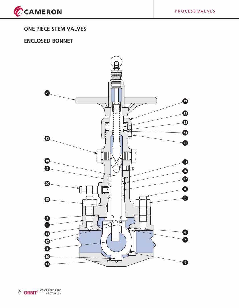
ONE PIECE STEM VALVES
6
11
12
13
14
10
9
8
7
6
5
4
3
2
1
25
26
24
23
22
21
20
19
18
17
16
15
®ORBIT
ENCLOSED BONNET
CT-ORB-TEC/REF/207/07 NP-2M
P R O C E S S V A L V E S
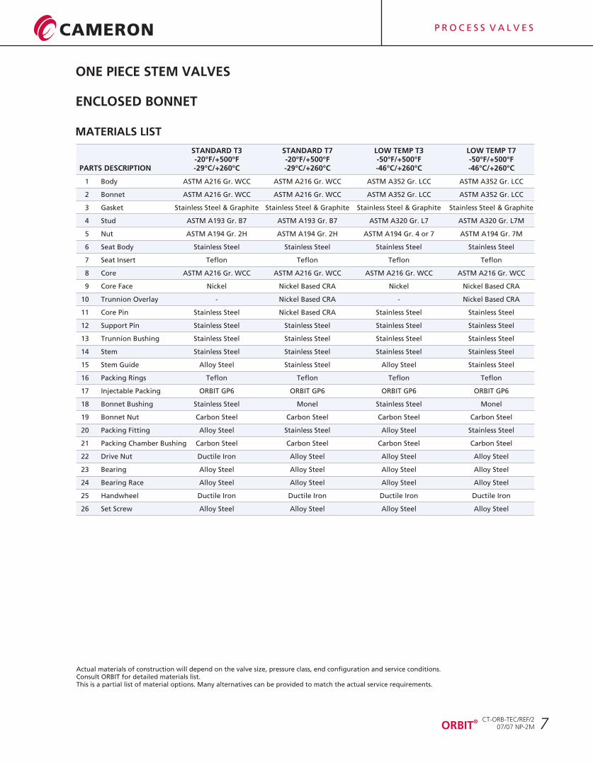
ONE PIECE STEM VALVES
Actual materials of construction will depend on the valve size, pressure class, end configuration and service conditions. Consult ORBIT for detailed materials list.This is a partial list of material options. Many alternatives can be provided to match the actual service requirements.
7
STANDARD T3 STANDARD T7 LOW TEMP T3 LOW TEMP T7-20°F/+500°F -20°F/+500°F -50°F/+500°F -50°F/+500°F
PARTS DESCRIPTION -29°C/+260°C -29°C/+260°C -46°C/+260°C -46°C/+260°C
1 Body ASTM A216 Gr. WCC ASTM A216 Gr. WCC ASTM A352 Gr. LCC ASTM A352 Gr. LCC
2 Bonnet ASTM A216 Gr. WCC ASTM A216 Gr. WCC ASTM A352 Gr. LCC ASTM A352 Gr. LCC
3 Gasket Stainless Steel & Graphite Stainless Steel & Graphite Stainless Steel & Graphite Stainless Steel & Graphite
4 Stud ASTM A193 Gr. B7 ASTM A193 Gr. B7 ASTM A320 Gr. L7 ASTM A320 Gr. L7M
5 Nut ASTM A194 Gr. 2H ASTM A194 Gr. 2H ASTM A194 Gr. 4 or 7 ASTM A194 Gr. 7M
6 Seat Body Stainless Steel Stainless Steel Stainless Steel Stainless Steel
7 Seat Insert Teflon Teflon Teflon Teflon
8 Core ASTM A216 Gr. WCC ASTM A216 Gr. WCC ASTM A216 Gr. WCC ASTM A216 Gr. WCC
9 Core Face Nickel Nickel Based CRA Nickel Nickel Based CRA
10 Trunnion Overlay - Nickel Based CRA - Nickel Based CRA
11 Core Pin Stainless Steel Nickel Based CRA Stainless Steel Stainless Steel
12 Support Pin Stainless Steel Stainless Steel Stainless Steel Stainless Steel
13 Trunnion Bushing Stainless Steel Stainless Steel Stainless Steel Stainless Steel
14 Stem Stainless Steel Stainless Steel Stainless Steel Stainless Steel
15 Stem Guide Alloy Steel Stainless Steel Alloy Steel Stainless Steel
16 Packing Rings Teflon Teflon Teflon Teflon
17 Injectable Packing ORBIT GP6 ORBIT GP6 ORBIT GP6 ORBIT GP6
18 Bonnet Bushing Stainless Steel Monel Stainless Steel Monel
19 Bonnet Nut Carbon Steel Carbon Steel Carbon Steel Carbon Steel
20 Packing Fitting Alloy Steel Stainless Steel Alloy Steel Stainless Steel
21 Packing Chamber Bushing Carbon Steel Carbon Steel Carbon Steel Carbon Steel
22 Drive Nut Ductile Iron Alloy Steel Alloy Steel Alloy Steel
23 Bearing Alloy Steel Alloy Steel Alloy Steel Alloy Steel
24 Bearing Race Alloy Steel Alloy Steel Alloy Steel Alloy Steel
25 Handwheel Ductile Iron Ductile Iron Ductile Iron Ductile Iron
26 Set Screw Alloy Steel Alloy Steel Alloy Steel Alloy Steel
MATERIALS LIST
®ORBIT
ENCLOSED BONNET
CT-ORB-TEC/REF/207/07 NP-2M

P R O C E S S V A L V E S
TWO PIECE STEM VALVES
ENCLOSED BONNET
8
11
12
13
14
109
8
7
6
5
4
3
2
1
25
26
24
23
29
21
20
19
18
17
16
15
27
28
®ORBIT
30
22
CT-ORB-TEC/REF/207/07 NP-2M
P R O C E S S V A L V E S
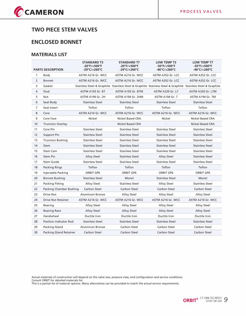
TWO PIECE STEM VALVES
ENCLOSED BONNET
Actual materials of construction will depend on the valve size, pressure class, end configuration and service conditions. Consult ORBIT for detailed materials list.This is a partial list of material options. Many alternatives can be provided to match the actual service requirements.
9
-20°F/+500°F -20°F/+500°F -50°F/+500°F -50°F/+500°F PARTS DESCRIPTION -29°C/+260°C -29°C/+260°C -46°C/+260°C -46°C/+260°C
1 Body ASTM A216 Gr. WCC ASTM A216 Gr. WCC ASTM A352 Gr. LCC ASTM A352 Gr. LCC
2 Bonnet ASTM A216 Gr. WCC ASTM A216 Gr. WCC ASTM A352 Gr. LCC ASTM A352 Gr. LCC
3 Gasket Stainless Steel & Graphite Stainless Steel & Graphite Stainless Steel & Graphite Stainless Steel & Graphite
4 Stud ASTM A193 Gr. B7 ASTM A193 Gr. B7M ASTM A320 Gr. L7 ASTM A320 Gr. L7M
5 Nut ASTM A194 Gr. 2H ASTM A194 Gr. 2HM ASTM A194 Gr. 7 ASTM A194 Gr. 7M
6 Seat Body Stainless Steel Stainless Steel Stainless Steel Stainless Steel
7 Seat Insert Teflon Teflon Teflon Teflon
8 Core ASTM A216 Gr. WCC ASTM A216 Gr. WCC ASTM A216 Gr. WCC ASTM A216 Gr. WCC
9 Core Face Nickel Nickel Based CRA Nickel Nickel Based CRA
10 Trunnion Overlay - Nickel Based CRA - Nickel Based CRA
11 Core Pin Stainless Steel Stainless Steel Stainless Steel Stainless Steel
12 Support Pin Stainless Steel Stainless Steel Stainless Steel Stainless Steel
13 Trunnion Bushing Stainless Steel Stainless Steel Stainless Steel Stainless Steel
14 Stem Stainless Steel Stainless Steel Stainless Steel Stainless Steel
15 Stem Cam Stainless Steel Stainless Steel Stainless Steel Stainless Steel
16 Stem Pin Alloy Steel Stainless Steel Alloy Steel Stainless Steel
17 Stem Guide Stainless Steel Stainless Steel Stainless Steel Stainless Steel
18 Packing Rings Teflon Teflon Teflon Teflon
19 Injectable Packing ORBIT GP6 ORBIT GP6 ORBIT GP6 ORBIT GP6
20 Bonnet Bushing Stainless Steel Monel Stainless Steel Monel
21 Packing Fitting Alloy Steel Stainless Steel Alloy Steel Stainless Steel
22 Packing Chamber Bushing Carbon Steel Carbon Steel Carbon Steel Carbon Steel
23 Drive Nut Aluminum Bronze Alloy Steel Alloy Steel Alloy Steel
24 Drive Nut Retainer ASTM A216 Gr. WCC ASTM A216 Gr. WCC ASTM A216 Gr. WCC ASTM A216 Gr. WCC
25 Bearing Alloy Steel Alloy Steel Alloy Steel Alloy Steel
26 Bearing Race Alloy Steel Alloy Steel Alloy Steel Alloy Steel
27 Handwheel Ductile Iron Ductile Iron Ductile Iron Ductile Iron
28 Position Indicator Rod Stainless Steel Stainless Steel Stainless Steel Stainless Steel
29 Packing Gland Aluminum Bronze Carbon Steel Carbon Steel Carbon Steel
30 Packing Gland Retainer Carbon Steel Carbon Steel Carbon Steel Carbon Steel
STANDARD T3 STANDARD T7 LOW TEMP T3 LOW TEMP T7
MATERIALS LIST
®ORBIT
CT-ORB-TEC/REF/207/07 NP-2M
P R O C E S S V A L V E S
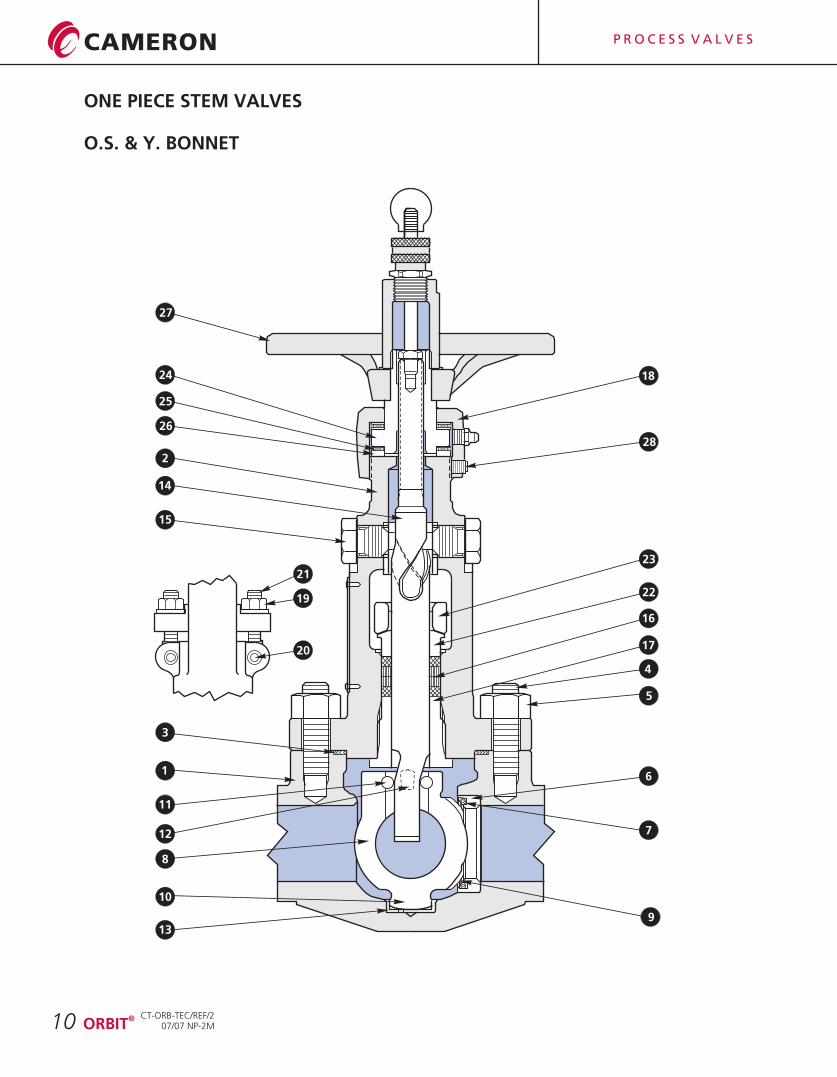
ONE PIECE STEM VALVES
O.S. & Y. BONNET
10 ®ORBIT
CT-ORB-TEC/REF/207/07 NP-2M
11
12
13
14
10
9
8
7
6
5
4
3
2
1
25
26
24
23
22
18
17
16
15
27
28
20
21
19
P R O C E S S V A L V E S
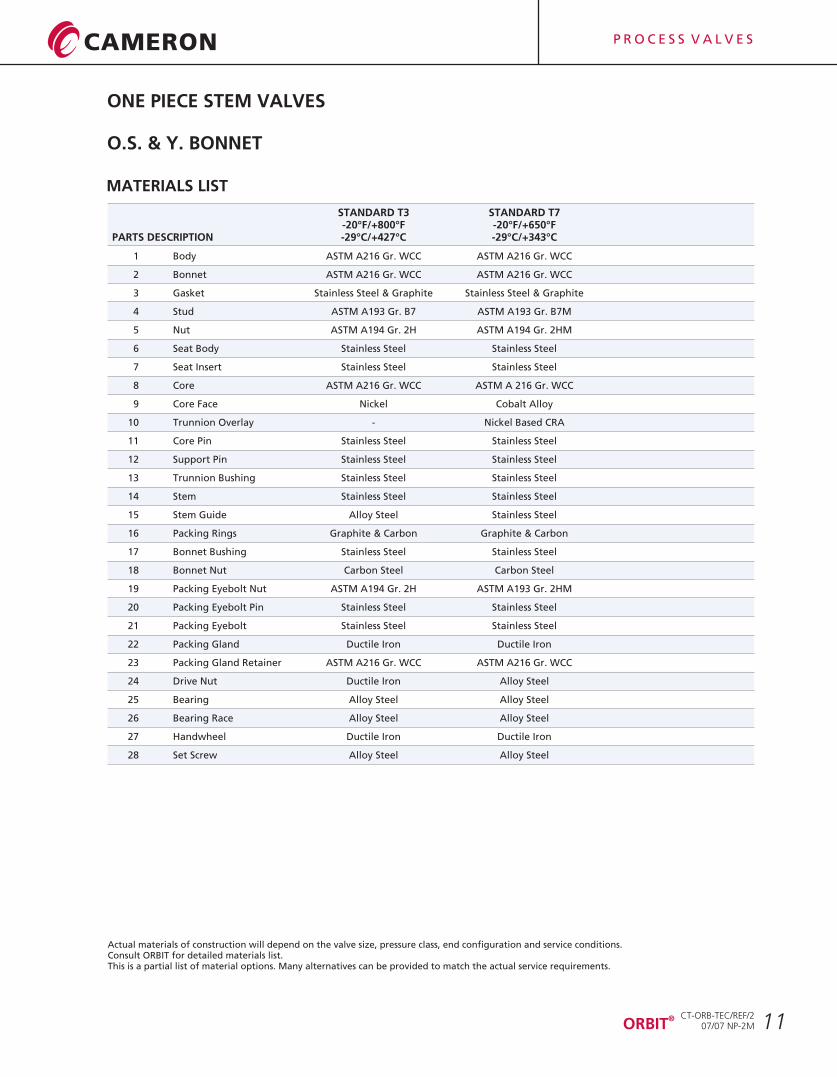
ONE PIECE STEM VALVES
O.S. & Y. BONNET
Actual materials of construction will depend on the valve size, pressure class, end configuration and service conditions. Consult ORBIT for detailed materials list.This is a partial list of material options. Many alternatives can be provided to match the actual service requirements.
STANDARD T3 STANDARD T7-20°F/+800°F -20°F/+650°F
PARTS DESCRIPTION -29°C/+427°C -29°C/+343°C
1 Body ASTM A216 Gr. WCC ASTM A216 Gr. WCC
2 Bonnet ASTM A216 Gr. WCC ASTM A216 Gr. WCC
3 Gasket Stainless Steel & Graphite Stainless Steel & Graphite
4 Stud ASTM A193 Gr. B7 ASTM A193 Gr. B7M
5 Nut ASTM A194 Gr. 2H ASTM A194 Gr. 2HM
6 Seat Body Stainless Steel Stainless Steel
7 Seat Insert Stainless Steel Stainless Steel
8 Core ASTM A216 Gr. WCC ASTM A 216 Gr. WCC
9 Core Face Nickel Cobalt Alloy
10 Trunnion Overlay - Nickel Based CRA
11 Core Pin Stainless Steel Stainless Steel
12 Support Pin Stainless Steel Stainless Steel
13 Trunnion Bushing Stainless Steel Stainless Steel
14 Stem Stainless Steel Stainless Steel
15 Stem Guide Alloy Steel Stainless Steel
16 Packing Rings Graphite & Carbon Graphite & Carbon
17 Bonnet Bushing Stainless Steel Stainless Steel
18 Bonnet Nut Carbon Steel Carbon Steel
19 Packing Eyebolt Nut ASTM A194 Gr. 2H ASTM A193 Gr. 2HM
20 Packing Eyebolt Pin Stainless Steel Stainless Steel
21 Packing Eyebolt Stainless Steel Stainless Steel
22 Packing Gland Ductile Iron Ductile Iron
23 Packing Gland Retainer ASTM A216 Gr. WCC ASTM A216 Gr. WCC
24 Drive Nut Ductile Iron Alloy Steel
25 Bearing Alloy Steel Alloy Steel
26 Bearing Race Alloy Steel Alloy Steel
27 Handwheel Ductile Iron Ductile Iron
28 Set Screw Alloy Steel Alloy Steel
MATERIALS LIST
11®ORBIT
CT-ORB-TEC/REF/207/07 NP-2M

P R O C E S S V A L V E S
TWO PIECE STEM VALVES
O.S. & Y. BONNET
12
11
12
13
14
109
8
7
6
5
4
3
2
1
29
26
24
23
22
21
20
19
18
17
16
15
27
28
30
31
25
33
32
®ORBIT
CT-ORB-TEC/REF/207/07 NP-2M
P R O C E S S V A L V E S
TWO PIECE STEM VALVES
O.S. & Y. BONNET
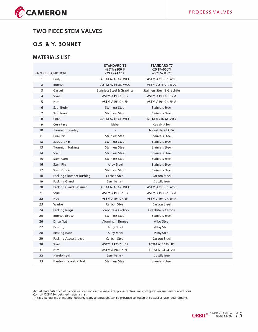
Actual materials of construction will depend on the valve size, pressure class, end configuration and service conditions. Consult ORBIT for detailed materials list.This is a partial list of material options. Many alternatives can be provided to match the actual service requirements.
13®ORBIT
STANDARD T3 STANDARD T7-20°F/+800°F -20°F/+650°F
PARTS DESCRIPTION -29°C/+427°C -29°C/+343°C
1 Body ASTM A216 Gr. WCC ASTM A216 Gr. WCC
2 Bonnet ASTM A216 Gr. WCC ASTM A216 Gr. WCC
3 Gasket Stainless Steel & Graphite Stainless Steel & Graphite
4 Stud ASTM A193 Gr. B7 ASTM A193 Gr. B7M
5 Nut ASTM A194 Gr. 2H ASTM A194 Gr. 2HM
6 Seat Body Stainless Steel Stainless Steel
7 Seat Insert Stainless Steel Stainless Steel
8 Core ASTM A216 Gr. WCC ASTM A 216 Gr. WCC
9 Core Face Nickel Cobalt Alloy
10 Trunnion Overlay - Nickel Based CRA
11 Core Pin Stainless Steel Stainless Steel
12 Support Pin Stainless Steel Stainless Steel
13 Trunnion Bushing Stainless Steel Stainless Steel
14 Stem Stainless Steel Stainless Steel
15 Stem Cam Stainless Steel Stainless Steel
16 Stem Pin Alloy Steel Stainless Steel
17 Stem Guide Stainless Steel Stainless Steel
18 Packing Chamber Bushing Carbon Steel Carbon Steel
19 Packing Gland Ductile Iron Ductile Iron
20 Packing Gland Retainer ASTM A216 Gr. WCC ASTM A216 Gr. WCC
21 Stud ASTM A193 Gr. B7 ASTM A193 Gr. B7M
22 Nut ASTM A194 Gr. 2H ASTM A194 Gr. 2HM
23 Washer Carbon Steel Carbon Steel
24 Packing Rings Graphite & Carbon Graphite & Carbon
25 Bonnet Sleeve Stainless Steel Stainless Steel
26 Drive Nut Aluminum Bronze Alloy Steel
27 Bearing Alloy Steel Alloy Steel
28 Bearing Race Alloy Steel Alloy Steel
29 Packing Access Sleeve Carbon Steel Carbon Steel
30 Stud ASTM A193 Gr. B7 ASTM A193 Gr. B7
31 Nut ASTM A194 Gr. 2H ASTM A194 Gr. 2H
32 Handwheel Ductile Iron Ductile Iron
33 Position Indicator Rod Stainless Steel Stainless Steel
MATERIALS LIST
CT-ORB-TEC/REF/207/07 NP-2M
P R O C E S S V A L V E S
END FLANGE BOLTING DIMENSIONS
14
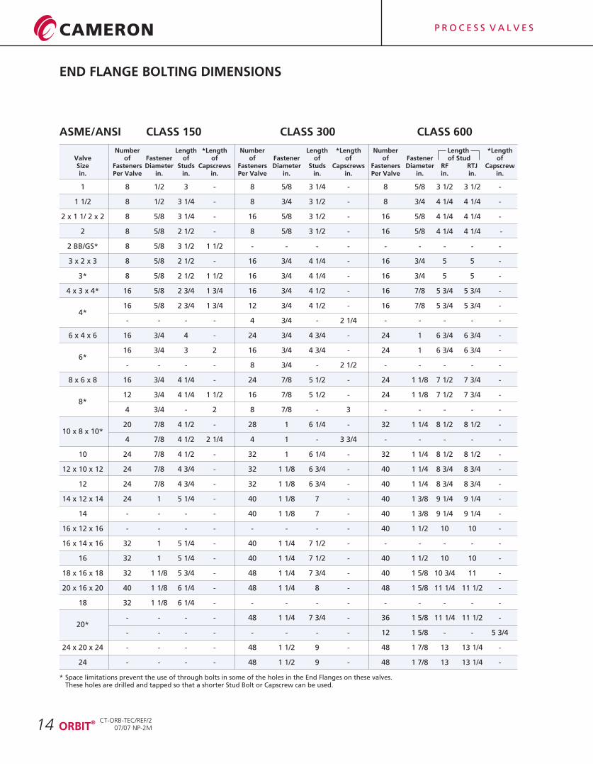
ASME/ANSI CLASS 150 CLASS 300 CLASS 600
* Space limitations prevent the use of through bolts in some of the holes in the End Flanges on these valves.These holes are drilled and tapped so that a shorter Stud Bolt or Capscrew can be used.
®ORBIT
CT-ORB-TEC/REF/207/07 NP-2M
*LengthValve of Fastener of of of Fastener of of of Fastener of Stud ofSize Fasteners Diameter Studs Capscrews Fasteners Diameter Studs Capscrews Fasteners Diameter RF RTJ Capscrewin. Per Valve in. in. in. Per Valve in. in. in. Per Valve in. in. in. in.
1 8 1/2 3 - 8 5/8 3 1/4 - 8 5/8 3 1/2 3 1/2 -
1 1/2 8 1/2 3 1/4 - 8 3/4 3 1/2 - 8 3/4 4 1/4 4 1/4 -
2 x 1 1/ 2 x 2 8 5/8 3 1/4 - 16 5/8 3 1/2 - 16 5/8 4 1/4 4 1/4 -
2 8 5/8 2 1/2 - 8 5/8 3 1/2 - 16 5/8 4 1/4 4 1/4 -
2 BB/GS* 8 5/8 3 1/2 1 1/2 - - - - - - - - -
3 x 2 x 3 8 5/8 2 1/2 - 16 3/4 4 1/4 - 16 3/4 5 5 -
3* 8 5/8 2 1/2 1 1/2 16 3/4 4 1/4 - 16 3/4 5 5 -
4 x 3 x 4* 16 5/8 2 3/4 1 3/4 16 3/4 4 1/2 - 16 7/8 5 3/4 5 3/4 -
16 5/8 2 3/4 1 3/4 12 3/4 4 1/2 - 16 7/8 5 3/4 5 3/4 -4*
- - - - 4 3/4 - 2 1/4 - - - - -
6 x 4 x 6 16 3/4 4 - 24 3/4 4 3/4 - 24 1 6 3/4 6 3/4 -
16 3/4 3 2 16 3/4 4 3/4 - 24 1 6 3/4 6 3/4 -6*
- - - - 8 3/4 - 2 1/2 - - - - -
8 x 6 x 8 16 3/4 4 1/4 - 24 7/8 5 1/2 - 24 1 1/8 7 1/2 7 3/4 -
12 3/4 4 1/4 1 1/2 16 7/8 5 1/2 - 24 1 1/8 7 1/2 7 3/4 -8*
4 3/4 - 2 8 7/8 - 3 - - - - -
20 7/8 4 1/2 - 28 1 6 1/4 - 32 1 1/4 8 1/2 8 1/2 -10 x 8 x 10*
4 7/8 4 1/2 2 1/4 4 1 - 3 3/4 - - - - -
10 24 7/8 4 1/2 - 32 1 6 1/4 - 32 1 1/4 8 1/2 8 1/2 -
12 x 10 x 12 24 7/8 4 3/4 - 32 1 1/8 6 3/4 - 40 1 1/4 8 3/4 8 3/4 -
12 24 7/8 4 3/4 - 32 1 1/8 6 3/4 - 40 1 1/4 8 3/4 8 3/4 -
14 x 12 x 14 24 1 5 1/4 - 40 1 1/8 7 - 40 1 3/8 9 1/4 9 1/4 -
14 - - - - 40 1 1/8 7 - 40 1 3/8 9 1/4 9 1/4 -
16 x 12 x 16 - - - - - - - - 40 1 1/2 10 10 -
16 x 14 x 16 32 1 5 1/4 - 40 1 1/4 7 1/2 - - - - - -
16 32 1 5 1/4 - 40 1 1/4 7 1/2 - 40 1 1/2 10 10 -
18 x 16 x 18 32 1 1/8 5 3/4 - 48 1 1/4 7 3/4 - 40 1 5/8 10 3/4 11 -
20 x 16 x 20 40 1 1/8 6 1/4 - 48 1 1/4 8 - 48 1 5/8 11 1/4 11 1/2 -
18 32 1 1/8 6 1/4 - - - - - - - - - -
- - - - 48 1 1/4 7 3/4 - 36 1 5/8 11 1/4 11 1/2 -20*
- - - - - - - - 12 1 5/8 - - 5 3/4
24 x 20 x 24 - - - - 48 1 1/2 9 - 48 1 7/8 13 13 1/4 -
24 - - - - 48 1 1/2 9 - 48 1 7/8 13 13 1/4 -
Number Length *Length Number Length *Length Number Length
P R O C E S S V A L V E S
END FLANGE BOLTING DIMENSIONS
15
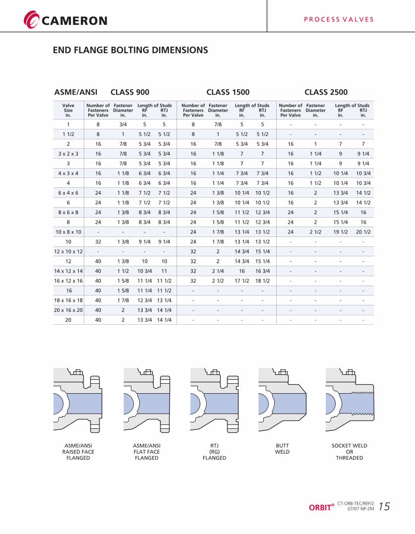
ASME/ANSIRAISED FACE
FLANGED
ASME/ANSIFLAT FACEFLANGED
RTJ(RG)
FLANGED
BUTTWELD
SOCKET WELDOR
THREADED
Valve Number of Fastener Length of Studs Number of Fastener Length of Studs Number of Fastener Length of StudsSize Fasteners Diameter RF RTJ Fasteners Diameter RF RTJ Fasteners Diameter RF RTJin. Per Valve in. in. in. Per Valve in. in. in. Per Valve in. in. in.
1 8 3/4 5 5 8 7/8 5 5 - - - -
1 1/2 8 1 5 1/2 5 1/2 8 1 5 1/2 5 1/2 - - - -
2 16 7/8 5 3/4 5 3/4 16 7/8 5 3/4 5 3/4 16 1 7 7
3 x 2 x 3 16 7/8 5 3/4 5 3/4 16 1 1/8 7 7 16 1 1/4 9 9 1/4
3 16 7/8 5 3/4 5 3/4 16 1 1/8 7 7 16 1 1/4 9 9 1/4
4 x 3 x 4 16 1 1/8 6 3/4 6 3/4 16 1 1/4 7 3/4 7 3/4 16 1 1/2 10 1/4 10 3/4
4 16 1 1/8 6 3/4 6 3/4 16 1 1/4 7 3/4 7 3/4 16 1 1/2 10 1/4 10 3/4
6 x 4 x 6 24 1 1/8 7 1/2 7 1/2 24 1 3/8 10 1/4 10 1/2 16 2 13 3/4 14 1/2
6 24 1 1/8 7 1/2 7 1/2 24 1 3/8 10 1/4 10 1/2 16 2 13 3/4 14 1/2
8 x 6 x 8 24 1 3/8 8 3/4 8 3/4 24 1 5/8 11 1/2 12 3/4 24 2 15 1/4 16
8 24 1 3/8 8 3/4 8 3/4 24 1 5/8 11 1/2 12 3/4 24 2 15 1/4 16
10 x 8 x 10 - - - - 24 1 7/8 13 1/4 13 1/2 24 2 1/2 19 1/2 20 1/2
10 32 1 3/8 9 1/4 9 1/4 24 1 7/8 13 1/4 13 1/2 - - - -
12 x 10 x 12 - - - - 32 2 14 3/4 15 1/4 - - - -
12 40 1 3/8 10 10 32 2 14 3/4 15 1/4 - - - -
14 x 12 x 14 40 1 1/2 10 3/4 11 32 2 1/4 16 16 3/4 - - - -
16 x 12 x 16 40 1 5/8 11 1/4 11 1/2 32 2 1/2 17 1/2 18 1/2 - - - -
16 40 1 5/8 11 1/4 11 1/2 - - - - - - - -
18 x 16 x 18 40 1 7/8 12 3/4 13 1/4 - - - - - - - -
20 x 16 x 20 40 2 13 3/4 14 1/4 - - - - - - - -
20 40 2 13 3/4 14 1/4 - - - - - - - -
ASME/ANSI CLASS 900 CLASS 1500 CLASS 2500
®ORBIT
CT-ORB-TEC/REF/207/07 NP-2M
P R O C E S S V A L V E S
SEAT AND STEM PACKING SELECTION
16
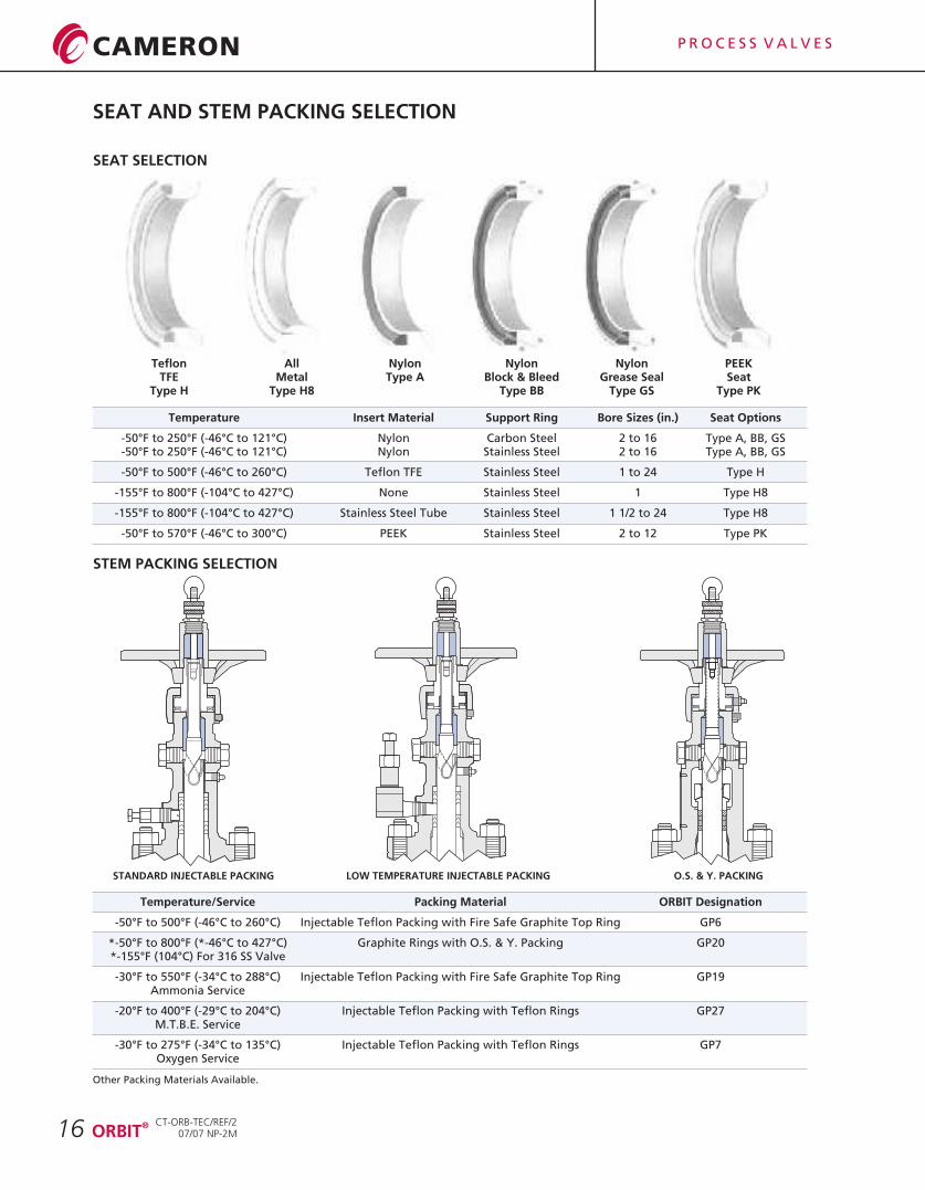
Temperature Insert Material Support Ring Bore Sizes (in.) Seat Options
Nylon Carbon Steel 2 to 16 Type A, BB, GS-50°F to 250°F (-46°C to 121°C) Nylon Stainless Steel 2 to 16 Type A, BB, GS
-50°F to 500°F (-46°C to 260°C) Teflon TFE Stainless Steel 1 to 24 Type H
-155°F to 800°F (-104°C to 427°C) None Stainless Steel 1 Type H8
-155°F to 800°F (-104°C to 427°C) Stainless Steel Tube Stainless Steel 1 1/2 to 24 Type H8
-50°F to 570°F (-46°C to 300°C) PEEK Stainless Steel 2 to 12 Type PK
-50°F to 250°F (-46°C to 121°C)
Temperature/Service Packing Material ORBIT Designation
-50°F to 500°F Injectable Teflon Packing with Fire Safe Graphite Top Ring GP6
*-50°F to 800°F (*-46°C to 427°C) Graphite Rings with O.S. & Y. Packing GP20*-155°F (104°C) For 316 SS Valve
-30°F to 550°F (-34°C to 288°C) Injectable Teflon Packing with Fire Safe Graphite Top Ring GP19Ammonia Service
-20°F to 400°F (-29°C to 204°C) Injectable Teflon Packing with Teflon Rings GP27M.T.B.E. Service
-30°F to 275°F (-34°C to 135°C) Injectable Teflon Packing with Teflon Rings GP7Oxygen Service
Other Packing Materials Available.
(-46°C to 260°C)
SEAT SELECTION
STANDARD INJECTABLE PACKING LOW TEMPERATURE INJECTABLE PACKING O.S. & Y. PACKING
TeflonTFE
Type H
STEM PACKING SELECTION
AllMetal
Type H8
NylonType A
NylonBlock & Bleed
Type BB
NylonGrease Seal
Type GS
PEEKSeat
Type PK
®ORBIT
CT-ORB-TEC/REF/207/07 NP-2M
P R O C E S S V A L V E S
17
NAMEPLATE MARKINGS FOR VALVE TRIM
AS Alloy Steel
®15-6 Carpenter 450 Stainless Steel
660 A-638 (Grade 660)
®HF-C Hardfacing Hastelloy C and C-276
®C-276 Hastelloy C-276
®MP35N Latrobe
®CO-U Cobalt-Based-Ultimet
®NICU Monel
NI Nickel
®COCR Stellite
17-4 17-4PH Stainless Steel
CR13 410 Stainless Steel (13% Chrome)
®718 Inconel 718
316 Stainless Steel
NYL Nylon
®PEEK Poly-Ether-Ether-Ketone
®TEF Teflon
NAMEPLATE MARKINGS FOR STEM PACKING
GP-6 General Service
GP-7 Oxygen Service
GP-19 Ammonia Service
GP-27 MTBE Service
GP-20 Graphite O.S. & Y. Service
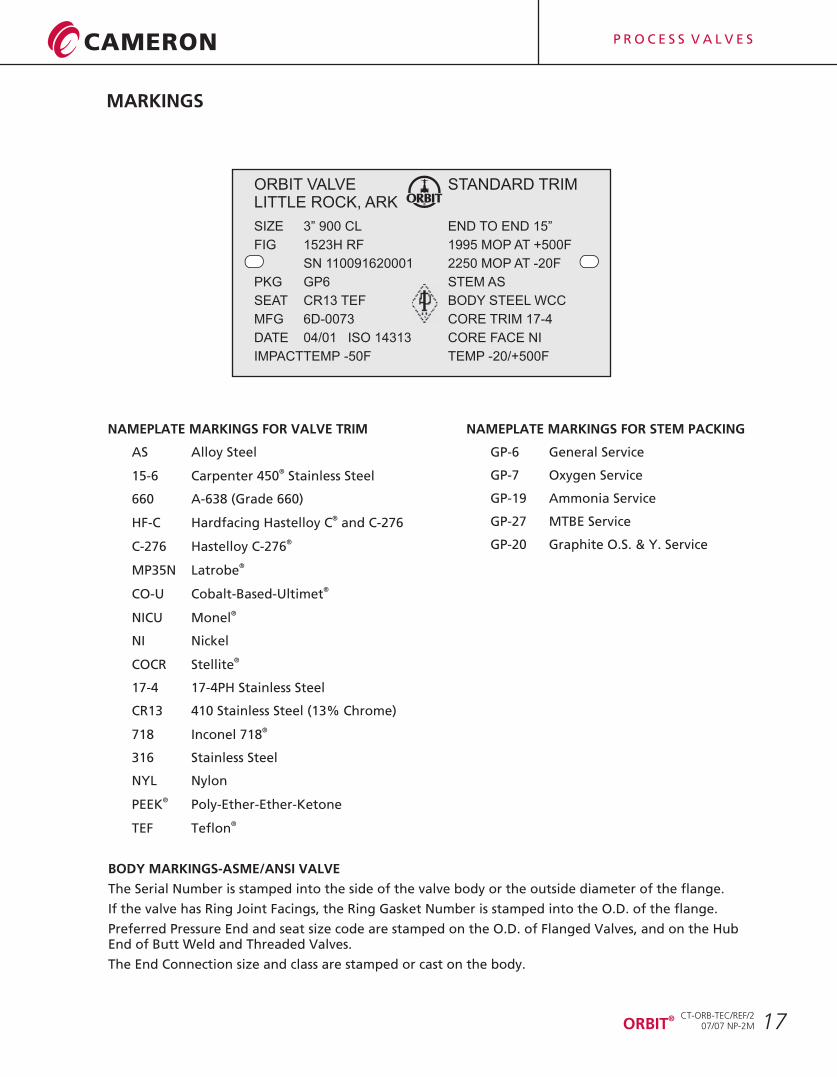
BODY MARKINGS-ASME/ANSI VALVE
The Serial Number is stamped into the side of the valve body or the outside diameter of the flange.
If the valve has Ring Joint Facings, the Ring Gasket Number is stamped into the O.D. of the flange.
Preferred Pressure End and seat size code are stamped on the O.D. of Flanged Valves, and on the Hub End of Butt Weld and Threaded Valves.
The End Connection size and class are stamped or cast on the body.
ORBIT VALVE STANDARD TRIMLITTLE ROCK, ARK
SIZE 3” 900 CL END TO END 15”
FIG 1523H RF 1995 MOP AT +500F
SN 110091620001 2250 MOP AT -20F
PKG GP6 STEM AS
SEAT CR13 TEF BODY STEEL WCC
MFG 6D-0073 CORE TRIM 17-4
DATE 04/01 ISO 14313 CORE FACE NI
IMPACTTEMP -50F TEMP -20/+500F
®ORBIT
MARKINGS
CT-ORB-TEC/REF/207/07 NP-2M
P R O C E S S V A L V E S
PRESSURE TESTING AND PRESSURE DROP FORMULAS
18
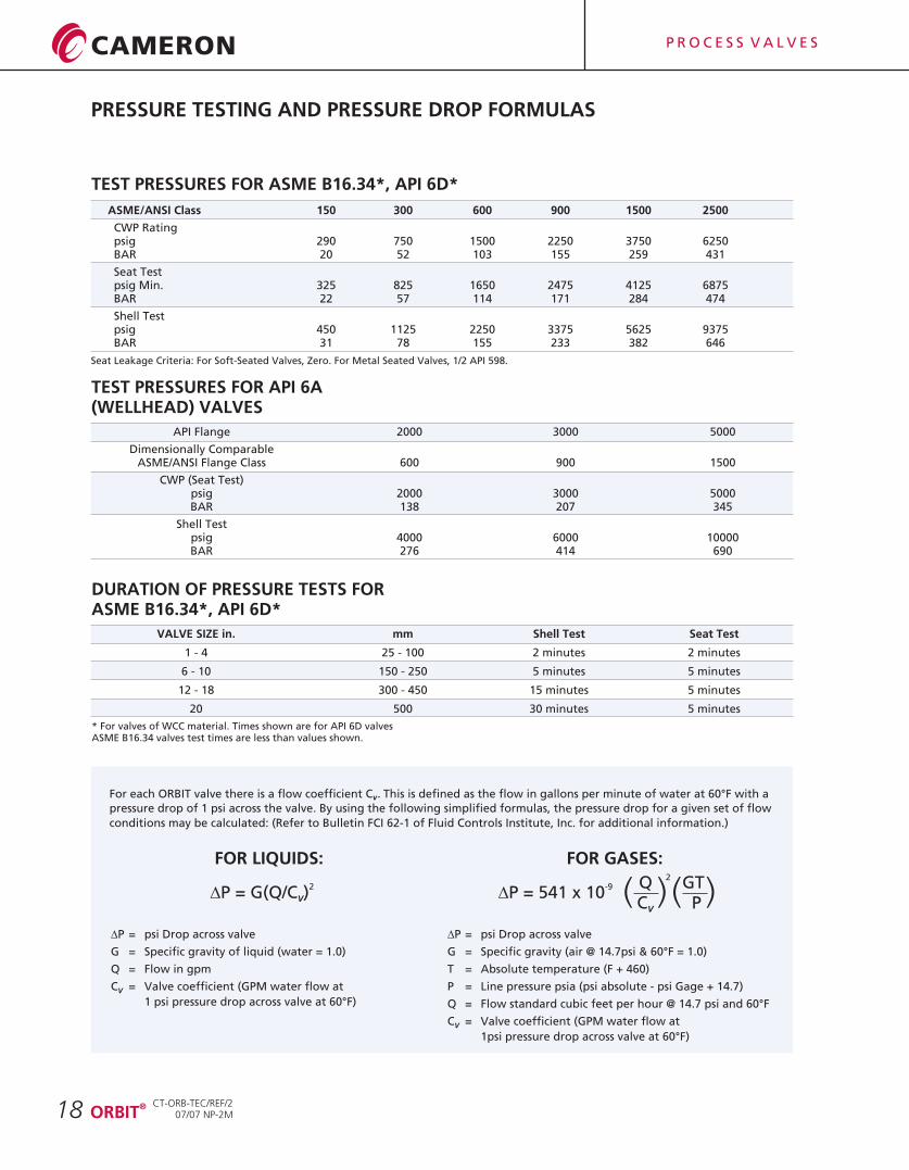
TEST PRESSURES FOR ASME B16.34*, API 6D*
ASME/ANSI Class 150 300 600 900 1500 2500
CWP Ratingpsig 290 750 1500 2250 3750 6250BAR 20 52 103 155 259 431
Seat Testpsig Min. 325 825 1650 2475 4125 6875BAR 22 57 114 171 284 474
Shell Testpsig 450 1125 2250 3375 5625 9375BAR 31 78 155 233 382 646
TEST PRESSURES FOR API 6A (WELLHEAD) VALVES
API Flange 2000 3000 5000
Dimensionally ComparableASME/ANSI Flange Class 600 900 1500
CWP (Seat Test)psig 2000 3000 5000BAR 138 207 345
Shell Testpsig 4000 6000 10000BAR 276 414 690
DURATION OF PRESSURE TESTS FORASME B16.34*, API 6D*
VALVE SIZE in. mm Shell Test Seat Test
1 - 4 25 - 100 2 minutes 2 minutes
6 - 10 150 - 250 5 minutes 5 minutes
12 - 18 300 - 450 15 minutes 5 minutes
20 500 30 minutes 5 minutes
* For valves of WCC material. Times shown are for API 6D valvesASME B16.34 valves test times are less than values shown.
For each ORBIT valve there is a flow coefficient C . This is defined as the flow in gallons per minute of water at 60°F with a V
pressure drop of 1 psi across the valve. By using the following simplified formulas, the pressure drop for a given set of flow
conditions may be calculated: (Refer to Bulletin FCI 62-1 of Fluid Controls Institute, Inc. for additional information.)
FOR LIQUIDS: FOR GASES:
DP = psi Drop across valve
G = Specific gravity of liquid (water = 1.0)
Q = Flow in gpm
C = Valve coefficient (GPM water flow at V
1 psi pressure drop across valve at 60°F)
DP = psi Drop across valve
G = Specific gravity (air @ 14.7psi & 60°F = 1.0)
T = Absolute temperature (F + 460)
P = Line pressure psia (psi absolute - psi Gage + 14.7)
Q = Flow standard cubic feet per hour @ 14.7 psi and 60°F
C = Valve coefficient (GPM water flow at V
1psi pressure drop across valve at 60°F)
2DP = G(Q/C )V
-9DP = 541 x 10 ( )Q
CV
2
( )GTP
Seat Leakage Criteria: For Soft-Seated Valves, Zero. For Metal Seated Valves, 1/2 API 598.
®ORBIT
CT-ORB-TEC/REF/207/07 NP-2M
P R O C E S S V A L V E S
ACTUATOR FIGURE NUMBERS
19
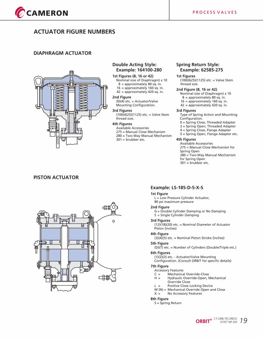
DIAPHRAGM ACTUATOR
PISTON ACTUATOR
Double Acting Style:Example: 164100-280
1st Figures (8, 16 or 42)Nominal size of Diaphragm) x 10
8 = approximately 80 sq. in.16 = approximately 160 sq. in.42 = approximately 420 sq. in.
2nd Figure(0)(4) etc. = Actuator/Valve Mounting Configuration.
3rd Figures(100)(625)(1125) etc. = Valve Stem thread size.
4th FiguresAvailable Accessories275 = Manual Close Mechanism280 = Two-Way Manual Mechanism301 = Snubber etc.
Spring Return Style:Example: 62585-275
1st Figures(thread size.
2nd Figure (8, 16 or 42)Nominal size of Diaphragm) x 10
8 = approximately 80 sq. in.16 = approximately 160 sq. in.42 = approximately 420 sq. in.
3rd FiguresType of Spring Action and Mounting Configuration.0 = Spring Close, Threaded Adapter3 = Spring Open, Threaded Adapter4 = Spring Close, Flange Adapter5 = Spring Open, Flange Adapter etc.
4th FiguresAvailable Accessories275 = Manual Close Mechanism for Spring Open280 = Two-Way Manual Mechanism for Spring Open301 = Snubber etc.
100)(625)(1125) etc. = Valve Stem
Example: LS-185-D-5-X-S
1st FigureL = Low Pressure Cylinder Actuator, 80 psi maximum pressure
2nd FigureG = Double Cylinder Damping or No DampingS = Single Cylinder Damping
3rd Figures(12)(18)(20) etc. = Nominal Diameter of Actuator Piston (inches)
4th Figure(3)(4)(5) etc. = Nominal Piston Stroke (inches)
5th Figure(D)(T) etc. = Number of Cylinders (Double/Triple etc.)
6th Figures(1)(2)(3) etc. - Actuator/Valve Mounting Configuration. (Consult ORBIT for specific details)
7th FigureAccessory FeaturesC = Mechanical Override-CloseH = Hydraulic Override-Open, Mechanical Override CloseL = Positive Close Locking DeviceM (N) = Mechanical Override Open and CloseX = No Accessory Features
8th FigureS = Spring Return
®ORBIT
CT-ORB-TEC/REF/207/07 NP-2M

P R O C E S S V A L V E S
ACTUATOR FIGURE NUMBERS
20
Valve Double Spring SpringSize Acting Close Open Acting Close Open Acting Close Openin. Actuator Actuator Actuator Actuator Actuator Actuator Actuator Actuator Actuator
1 84625 62584 62588 84625 62584 62588 84625 62584 62588
1 1/2 84625 62584 62588 84625 62584 62588 84625 62584 62588
2 84625 62584 62588 84625 62584 62588 84625 62584 62588
3 84100 100164 100165 84100 100164 100165 164100 100164 100165
4 84100 100164 100165 84100 100164 100165 164100 100167 100165
6 164100 100167 100167 164100 100167 * 164100 123424 *
8 164100 123424 * 164100 123424 * 424125-301 LS-185-D-25-X-S *
10 424125-301 125424 * 424125-301 LS-185-D-25-X-S * LS-185-D-5 LS-205-D-5-X-S *
12 LS-185-D-5 LS-185-D-5-X-S * LS-185-D-5 LS-205-D-5-X-S * LS-205-D-6 LS-205-D-6-X-S *
14 - - - LS-185-D-5 LS-205-D-X-S * LS-267-D-19 LS-267-D-19-X-S *
16 LS-207-D-19 LS-267-D-X-S * LS-207-D-19 LS-267-D-19-X-S * LS-267-D-19 LS-267-D-19-X-S *
18 LS-267-D-19 - - - - - - - -
20 - - - LS-2611-T-29 - - LS-2611-T-29 - -
24 - - - LS-4214-D-33 - - LS-4214-D-33 - -
Double Spring Spring Double Spring Spring
ASME/ANSI CLASS 150 CLASS 300 CLASS 600
These are typical selections of Actuators for Soft Seated Valves with standard T3 Trim and pipeline pressure from the preferred End. The correct choice of Actuator will depend on pressure direction, temperature, flow conditions, Valve Trim and Valve End Connections.
Consult ORBIT for specific Actuator/Valve combination that is most suitable for the intended service.
ELECTRIC ACTUATORS - Cameron’s Valves & Measurement group supplies Electric Actuated Valve Packages using many of the commercially available power actuators built by other companies.
The Electric Actuator is selected, mounted, adjusted and tested by ORBIT so that field performance of the entire valve assembly can be assured.
*Consult Factory
Valve Double Spring SpringSize Acting Close Open Acting Close Open Acting Close Openin. Actuator Actuator Actuator Actuator Actuator Actuator Actuator Actuator Actuator
1 1/2 164100 100164 * 164100 100164 * - - -
1 3/4 - - - - - - 164100 100164 *
2 164100 100164 100165 164100 100164 100165 - - -
3 164100 100164 100165 164100 100167 * 164101 120424 *
4 164100 100167 * 164100 121424 * 424125-301 125424 *
6 424125-301 LS-185-D-25-X-S * LS-185-D-5 LS-205-D-5-X-S * LS-185-D-5 LS-205-D-5-X-S *
8 LS-185-D-15 LS-205-D-15-X-S * LS-208-D-31 * * LS-269-D-32 * *
10 LS-205-D-16 LS-205-D-16-X-S * LS-269-D-32 * * - - -
12 LS-267-D-19 LS-267-D-19-X-S * LS-2611-T-29 * * - - -
16 LS-2611-T-29 - - - - - - - -
Double Spring Spring Double Spring Spring
1 84625 62584 62588 84625 62584 62588 84625 62584 62588
ASME/ANSI CLASS 900 CLASS 1500 CLASS 2500
*Consult Factory
®ORBIT
CT-ORB-TEC/REF/207/07 NP-2M
P R O C E S S V A L V E S
TRADEMARK INFORMATION
21®ORBIT
®ORBIT is a registered trademark which is owned by Cameron.
This document contains references to registered trademarks or product designations,
which are not owned by Cameron.
Trademark Owner
CARPENTER 450 Carpenter Technology Corp.
HASTELLOY Haynes International, Inc.
INCONEL INCO Nickel Sales, Inc.
LATROBE Timkin Latrobe Steel
MONEL INCO Alloys International, Inc.
PEEK Victrex PLC Corp United Kingdom
STELLITE Stoody Deloro Stellite, Inc.
TEFLON E.I. DuPont De Nemours & Company
ULTIMET Haynes International, Inc.
VITON E.I. DuPont De Nemours & Company
CT-ORB-TEC/REF/207/07 NP-2M

P R O C E S S V A L V E S
Printed in Canada 07/07-NP-2M CT-ORB-TEC/REF/2
For the most current contact and location information go to: www.c-a-m.com
VALVES & MEASUREMENT3250 Briarpark Drive, Suite 300Houston, Texas 77042USA Toll Free 800 323 9160