Embed Size (px)
Citation preview
Optotrak CertusMarker Strober Guide
Revision 2August 2005
IMPORTANTPlease read this entire documentbefore using the Marker Strober

Copyright 2005 Northern Digital Inc. All Rights Reserved.
p Printed in Canada.
Part number: IL-1070074
Revision Status
Revision Number Date DescriptionRevision 2 31/08/05 Removed ToolBench reference. General
update

Disclaimer of Warranties and Limitation of Liability
Published by: Northern Digital Inc.103 Randall Dr.Waterloo, Ontario, Canada N2V 1C5Telephone: +1 (519) 884-5142Toll Free: +1 (877) 634 634 0Global: ++ (800) 634 634 00Facsimile: +1 (519) 884-5184Website: www.ndigital.com
Copyright 2005, Northern Digital Inc.All rights reserved. No part of this document may be reproduced, transcribed, trans-mitted, distributed, modified, merged, translated into any language or used in any form by any means - graphic, electronic, or mechanical, including but not limited to photocopying, recording, taping or information storage and retrieval systems - without the prior written consent of Northern Digital Inc. Certain copying of the software included herein is unlawful. Refer to your software license agreement for information respecting permitted copying.
Disclaimer of Warranties and Limitation of Liabilities
Northern Digital Inc. has taken due care in preparing this document and the programs and data on the electronic media accompanying this document including research, development, and testing.This document describes the state of Northern Digital Inc.’s knowledge respecting the subject matter herein at the time of its publication, and may not reflect its state of knowledge at all times in the future. Northern Digital Inc. has carefully reviewed this document for technical accuracy. If errors are suspected, the user should consult with Northern Digital Inc. prior to proceeding. Northern Digital Inc. makes no expressed or implied warranty of any kind with regard to this document or the programs and data on the electronic media accompanying this document. Northern Digital Inc. makes no representation, condition or warranty to the user or any other party with respect to the adequacy of this document for any particular pur-pose or with respect to its adequacy to produce a particular result. The user’s right to recover damages caused by fault or negligence on the part of Northern Digital Inc. shall be limited to the amount paid by the user to Northern Digital Inc. for the provi-sion of this document. In no event shall Northern Digital Inc. be liable for special, col-
Optotrak Certus Marker Strober Guide - Revision 2

lateral, incidental, direct, indirect or consequential damages, losses, costs, charges, claims, demands, or claim for lost profits, data, fees or expenses of any nature or kind.Product names listed are trademarks of their respective manufacturers. Company names listed are trademarks or trade names of their respective companies.
Optotrak Certus Marker Strober Guide - Revision 2
Table of Contents
Table of Contents
Read Me First! . . . . . . . . . . . . . . . . . . . . . . . . . . . . . . . . . . . . . . . . . . . . . . iii
Warnings . . . . . . . . . . . . . . . . . . . . . . . . . . . . . . . . . . . . . . . . . . . . . . . iiiCautions . . . . . . . . . . . . . . . . . . . . . . . . . . . . . . . . . . . . . . . . . . . . . . . . iiiContact Information . . . . . . . . . . . . . . . . . . . . . . . . . . . . . . . . . . . . . . . ivUpdates. . . . . . . . . . . . . . . . . . . . . . . . . . . . . . . . . . . . . . . . . . . . . . . . . iv
1 Introduction . . . . . . . . . . . . . . . . . . . . . . . . . . . . . . . . . . . . . . . . . . . . . 1
1.1 Related Accessories . . . . . . . . . . . . . . . . . . . . . . . . . . . . . . . . . . . . 1
2 Strober Capabilities. . . . . . . . . . . . . . . . . . . . . . . . . . . . . . . . . . . . . . . 2
2.1 LED and Switch Support . . . . . . . . . . . . . . . . . . . . . . . . . . . . . . . . 2 2.2 Communications . . . . . . . . . . . . . . . . . . . . . . . . . . . . . . . . . . . . . . 2 2.3 Compatibility . . . . . . . . . . . . . . . . . . . . . . . . . . . . . . . . . . . . . . . . . 2 2.4 Convenience. . . . . . . . . . . . . . . . . . . . . . . . . . . . . . . . . . . . . . . . . . 3 2.5 Software Configuration . . . . . . . . . . . . . . . . . . . . . . . . . . . . . . . . . 3
3 Connecting the Strober to the System Control Unit . . . . . . . . . . . . 4
3.1 Strober Port Connections . . . . . . . . . . . . . . . . . . . . . . . . . . . . . . . . 5 3.2 Strober Status LED . . . . . . . . . . . . . . . . . . . . . . . . . . . . . . . . . . . . 5 3.3 Marker Port Connectors . . . . . . . . . . . . . . . . . . . . . . . . . . . . . . . . . 6 3.4 Strober Activation Order . . . . . . . . . . . . . . . . . . . . . . . . . . . . . . . . 6 3.5 Strober Extension Cable. . . . . . . . . . . . . . . . . . . . . . . . . . . . . . . . . 7 3.6 Connecting Markers to the Strober . . . . . . . . . . . . . . . . . . . . . . . . 8
4 Using the Swivel Clip . . . . . . . . . . . . . . . . . . . . . . . . . . . . . . . . . . . . . 9
4.1 Fastening the Tab to the Strober . . . . . . . . . . . . . . . . . . . . . . . . . . 9 4.2 Clip Orientation . . . . . . . . . . . . . . . . . . . . . . . . . . . . . . . . . . . . . . 10
Optotrak Certus Marker Strober Guide - Revision 2 i
Table of Contents
4.3 Removing the Strober from the Swivel Clip . . . . . . . . . . . . . . . .11
5 Wiring Markers and Switches . . . . . . . . . . . . . . . . . . . . . . . . . . . . . .12
5.1 Wiring Markers Into an RJH Connector . . . . . . . . . . . . . . . . . . .12 5.2 Wiring Switches . . . . . . . . . . . . . . . . . . . . . . . . . . . . . . . . . . . . . .16
6 Abbreviations and Acronyms . . . . . . . . . . . . . . . . . . . . . . . . . . . . . .18
7 Equipment Symbols. . . . . . . . . . . . . . . . . . . . . . . . . . . . . . . . . . . . . .19
ii Optotrak Certus Marker Strober Guide - Revision 2
Read Me First!
Read Me First!Read this section before continuing with the rest of the guide.
Warnings
In all NDI documentation, warnings are marked by this symbol. Follow the information in the accompanying paragraph to avoid personal injury.
1. An e-type strober must be connected to an e-type port on the e-type System Control Unit to maintain Type BF isolation. Check that the colours of both connectors match. The keying for the different types of connectors is unique to prevent using an s-type strober in and e-type port.
2. The s-type marker strober is not suitable for patient applied parts.
3. To maintain type BF isolation, all components between the e-type ports on an e-type System Control Unit and the patient must meet or exceed the certifications and approvals of the Optotrak Certus System. Serious personal injusry could result if the appropriate type of isolation is not maintained.
Cautions
Caution! In all NDI documentation, cautions are marked with the word "Caution!". Follow the information in the accompanying paragraph to avoid damage to equipment.
Do not plug telephone or other telecommunications devices into the marker port connectors. Telecommunications devices could be damaged by the marker strober.
Warning!
Optotrak Certus Marker Strober Guide - Revision 2 iii

Read Me First!
Contact InformationIf you have any questions regarding the content of this guide or the operation of this product, please contact us:
UpdatesNDI is committed to continuous improvements in the quality and versatility of its software and hardware. To obtain the best results with your NDI system, check the NDI Partner Site regularly for update information:
http://support.ndigital.com
iv Optotrak Certus Marker Strober Guide - Revision 2
Introduction
Optotrak Certus Marker Strober Guide - Revision 2 1
1 IntroductionThis guide contains information for both the e-type and s-type versions of the marker strober. To use this strober, you must be familiar with the Optotrak Certus System. Please see the “Optotrak Certus User Guide” for additional information about the Optotrak Certus System, including instructions on how to clean markers. Information on designing rigid bodies is included in the “Optotrak Certus Rigid Body and Tool Design Guide”.
E-type marker strobers will only connect to e-type Optotrak Certus System Control Units. S-type marker strobers can connect to s-type Optotrak Certus System Control Units and the s-type port on e-type Optotrak Certus System Control Units.
This strober can be used with switches and markers that you wire yourself. Wiring the switches requires you to have a basic knowledge of electronics and good wiring practices.
1.1 Related AccessoriesOther accessories that are available for the Optotrak Certus System include:
• axon strober, which has a DB25 connector that can be used for either markers, rigid bodies or tools
• tool strober, which has four, 10 pin, tool ports that accommodate tools with SROM files
• 3020 strober adapter, which allows Optotrak 3020 strobers to be used with the Optotrak Certus System
• markers with twisted pair cable and RJH connectors
• markers with twisted pair cable
• marker connector kit, which includes RJH plugs and a crimping tool
Strober Capabilities
2 Strober CapabilitiesThe marker strober is designed to allow up to 24 markers to be wired in groups of two, each group of two markers connecting into 1 of 12 RJH connectors.
Three strobers (marker, tool and axon), the strober extension cable, and the System Control Unit are available in both s-type and e-type configurations. The e-type components are intended for applications that require type BF isolation. The e-type System Control Unit includes two e-type strober ports and a single s-type strober port. All of the strober ports on the s-type System Control Unit are s-type.
2.1 LED and Switch SupportThe marker strober has a visible strober status LED and supports two optional, external switches connected directly to the strober through a headphone jack connection. The external switches are intended for feedback from the user to the application software. The signal returned from these switches is not fast enough to be considered real time, and cannot be used to synchronize the Optotrak Certus System with external devices.
2.2 CommunicationsThe strober receives marker activation information from the Optotrak Certus System and sends status information back to the system. The strober powers the markers in the order specified by software running on the host computer.
2.3 CompatibilityMarker strobers can be used simultaneously with other strobers, as well as the 3020 strober adapter. 3020 strober adapters, marker strobers and axon strobers can be mixed within a daisy chain; 3020 strober adapters must always be located at the end of the chain.
2 Optotrak Certus Marker Strober Guide - Revision 2
Strober Capabilities
2.4 ConvenienceThe RJH connectors provide maximum flexibility for changing marker configurations.
A swivel clip, which allows the strober to be attached to objects and rotate, is included with the strober. This facilitates fastening the strober to the subject.
2.5 Software ConfigurationUsing either NDI application software or the routines described in the device handle section of the Application Programmer’s Interface, you can set the:
• number of markers to be activated
• name of the strober
• order in which markers will be activated
• behaviour of the system in response to a change in the status of the switches
• information about a rigid body that includes the marker(s) being controlled by the strober
• marker voltage and frequency
Optotrak Certus Marker Strober Guide - Revision 2 3
Connecting the Strober to the System Control Unit
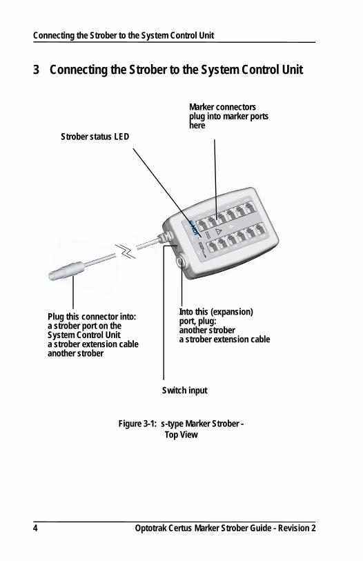
3 Connecting the Strober to the System Control Unit
Figure 3-1: s-type Marker Strober - Top View
Plug this connector into:a strober port on the System Control Unita strober extension cableanother strober
Into this (expansion) port, plug:another strobera strober extension cable
Switch input
Strober status LED
Marker connectors plug into marker ports here
4 Optotrak Certus Marker Strober Guide - Revision 2
Connecting the Strober to the System Control Unit
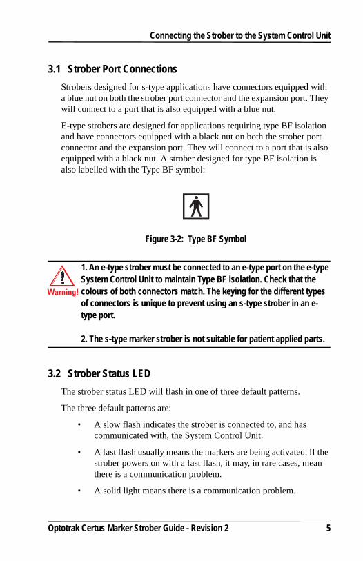
3.1 Strober Port ConnectionsStrobers designed for s-type applications have connectors equipped with a blue nut on both the strober port connector and the expansion port. They will connect to a port that is also equipped with a blue nut.
E-type strobers are designed for applications requiring type BF isolation and have connectors equipped with a black nut on both the strober port connector and the expansion port. They will connect to a port that is also equipped with a black nut. A strober designed for type BF isolation is also labelled with the Type BF symbol:
Figure 3-2: Type BF Symbol
1. An e-type strober must be connected to an e-type port on the e-type System Control Unit to maintain Type BF isolation. Check that the colours of both connectors match. The keying for the different types of connectors is unique to prevent using an s-type strober in an e-type port.
2. The s-type marker strober is not suitable for patient applied parts.
3.2 Strober Status LEDThe strober status LED will flash in one of three default patterns.
The three default patterns are:
• A slow flash indicates the strober is connected to, and has communicated with, the System Control Unit.
• A fast flash usually means the markers are being activated. If the strober powers on with a fast flash, it may, in rare cases, mean there is a communication problem.
• A solid light means there is a communication problem.
Warning!
Optotrak Certus Marker Strober Guide - Revision 2 5
Connecting the Strober to the System Control Unit
Note: More detailed technical descriptions of the Optotrak Certus System components are included in the “Optotrak Certus User Guide”.
3.3 Marker Port Connectors
Caution! Do not plug telephone or other telecommunications devices into the marker port connectors. Telecommunications devices could be damaged by the marker strober.
3.4 Strober Activation OrderThe order in which strobers and tools are activated is determined by the strober port to which they are connected. All the strobers which are connected to strober port 1 are activated before the strobers on port 2, which are activated before the strobers on port 3.
Tools and tool strobers are activated so that the tools connected to a tool strober are activated directly after the tool strober itself, and before the next strober in the chain. The tools are also activated in order ie a tool plugged into port [1] of a tool strober is activated before a tool plugged into port [2]. See Figure 3-3 on page 7, where the strobers and tools are numbered I to VIII.
While the strober activation order is fixed, the activation order of markers on each strober can be set in either the NDI application software or in the Application Programmer’s Interface.
6 Optotrak Certus Marker Strober Guide - Revision 2

Connecting the Strober to the System Control Unit
Figure 3-3: Strober and Tool Activation Order
3.5 Strober Extension CableThe strober extension cable can be used to increase the distance between:
• the strober and the System Control Unit
• two strobers
The distance from the strober to the System Control Unit should be as short as possible as the amount of power available to the markers decreases with both the length of the cable and the number of connectors.
Both s-type and e-type strober extension cables are available. Check that the colours of all connectors match each other. The keying for the different types of connectors is also unique to prevent using an s-type strober extension cable in an e-type port.
1 2 3
I
II
III
IV
VI
V
VIII
VII
System Control Unit
Strobers and Tools
Optotrak Certus Marker Strober Guide - Revision 2 7

Connecting the Strober to the System Control Unit
To maintain type BF isolation, all components between the e-type ports on an e-type System Control Unit and the patient must meet or exceed the certifications and approvals of the Optotrak Certus System. Serious personal injury could result if the appropriate type of isolation is not maintained.
3.6 Connecting Markers to the StroberThe markers are connected to an RJH connector through a twisted pair cable, of up to 3 m:
Figure 3-4: Markers with RJH Connector
Each marker connector can accommodate either one or two markers.
Marker and connector lifetimes will be maximized if you hold the connector when connecting and disconnecting the markers - not the wires.
The marker port number is shown beside each marker port.
Marker connectors do not have to be plugged into the marker ports sequentially. For example, marker connectors could be plugged into marker ports 1-2, 7-8, 15-16, and 21-22. In the application software, the marker activation order can be set, in any order, to activate either all markers or a subset of markers. This includes activating one marker only, when two markers are wired into a single connector.
3 m max
Side view
Warning!
8 Optotrak Certus Marker Strober Guide - Revision 2
Using the Swivel Clip
4 Using the Swivel ClipThe swivel clip consists of:
• a clip, which attaches to items such as a belt, collar or shoe.
• a tab, which is permanently fastened to the strober and can be quickly disconnected from the clip.
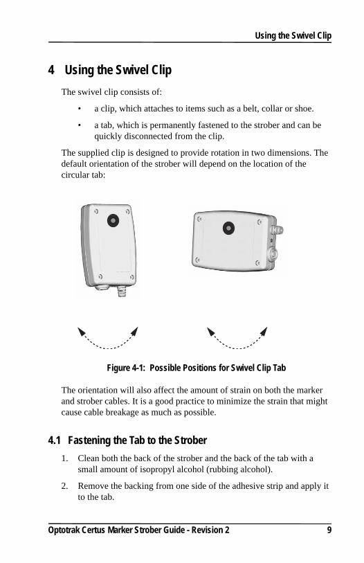
The supplied clip is designed to provide rotation in two dimensions. The default orientation of the strober will depend on the location of the circular tab:
Figure 4-1: Possible Positions for Swivel Clip Tab
The orientation will also affect the amount of strain on both the marker and strober cables. It is a good practice to minimize the strain that might cause cable breakage as much as possible.
4.1 Fastening the Tab to the Strober1. Clean both the back of the strober and the back of the tab with a
small amount of isopropyl alcohol (rubbing alcohol).
2. Remove the backing from one side of the adhesive strip and apply it to the tab.
Optotrak Certus Marker Strober Guide - Revision 2 9
Using the Swivel Clip
3. Remove the backing from the other side of the adhesive strip and press the tab firmly onto the back of the strober in the preferred location.
4. If possible, do not use the tab for 24 hours to allow the adhesive to set firmly.
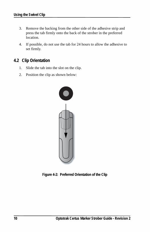
4.2 Clip Orientation 1. Slide the tab into the slot on the clip.
2. Position the clip as shown below:
Figure 4-2: Preferred Orientation of the Clip
10 Optotrak Certus Marker Strober Guide - Revision 2
Using the Swivel Clip
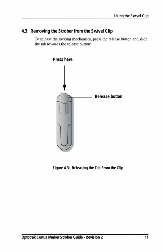
4.3 Removing the Strober from the Swivel ClipTo release the locking mechanism, press the release button and slide the tab towards the release button:
Figure 4-3: Releasing the Tab From the Clip
Press here
Release button
Optotrak Certus Marker Strober Guide - Revision 2 11
Wiring Markers and Switches
5 Wiring Markers and SwitchesMarkers purchased with twisted pair cables, but no connectors, will need to be connected to an RJH connector before they can be used with the marker strober.
Optional switches are provided by the user. These are wired to a 2.5 mm headphone jack, also supplied by the user. You must have a basic knowledge of electronics and good wiring practices to wire the headphone jack.
5.1 Wiring Markers Into an RJH ConnectorMarkers can be wired into a connector either singly or as a pair. You will need:
• markers, each connected to a twisted pair cable, available from NDI
• RJH connectors, available from NDI or an electronics shop
• crimping tool for RJH connectors, available from NDI or an electronics shop
• the connectors and crimping tool are available from NDI as a connector kit
1. Untwist about 50 mm of the twisted pair cable attached to a marker.
2. When connecting a pair of markers to the RJH connector, arrange the individual wires so that the copper and tinned wires are arranged as:
12 Optotrak Certus Marker Strober Guide - Revision 2

Wiring Markers and Switches
Figure 5-1: Marker Wire Arrangement
If only one marker (two wires) is being attached to the RJH connector, the copper wire should be on the inside. See “Inserting Wire into an RJH Connector” on page 14.
3. Smooth the wires so they lie flat and straight.
4. Holding the wires about 10 mm from the end, trim the wires even with either scissors or wire cutters.
Note Do not strip the wires or the connection will not work.
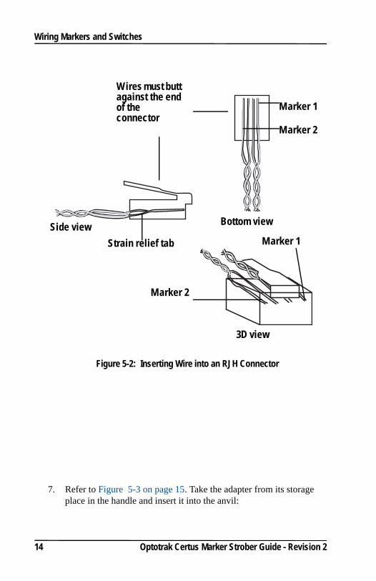
5. Insert the end of the wires into the RJH connector until the end of the wire reaches the far end of the connector:
6. Insert the strain relief tab into the back of the connector (where the wires were entered) so that it rests underneath the wires. This holds the wires up so they lie flat.
Copper wires
Tinned wires
Optotrak Certus Marker Strober Guide - Revision 2 13
Wiring Markers and Switches
Figure 5-2: Inserting Wire into an RJH Connector
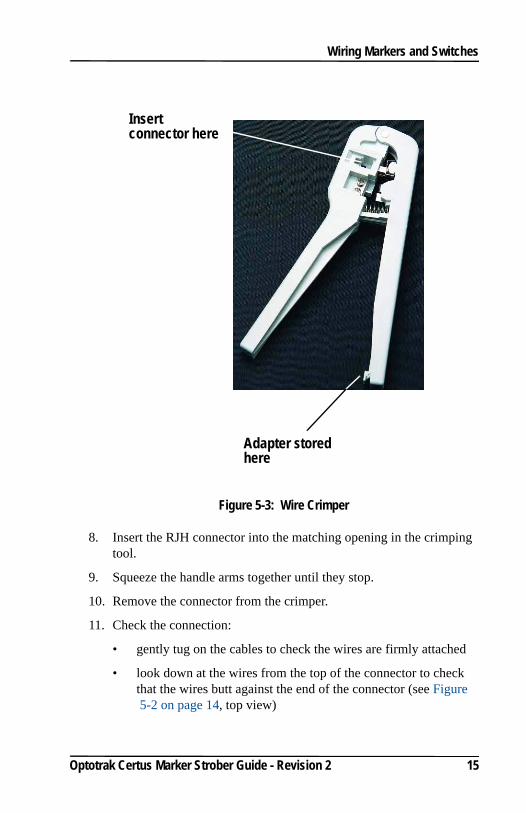
7. Refer to Figure 5-3 on page 15. Take the adapter from its storage place in the handle and insert it into the anvil:
Bottom viewSide view
Wires must butt against the end of the connector
Marker 1
Marker 2
Strain relief tab
3D view
Marker 1
Marker 2
14 Optotrak Certus Marker Strober Guide - Revision 2
Wiring Markers and Switches
Figure 5-3: Wire Crimper
8. Insert the RJH connector into the matching opening in the crimping tool.
9. Squeeze the handle arms together until they stop.
10. Remove the connector from the crimper.
11. Check the connection:
• gently tug on the cables to check the wires are firmly attached
• look down at the wires from the top of the connector to check that the wires butt against the end of the connector (see Figure 5-2 on page 14, top view)
Adapter stored here
Insert connector here
Optotrak Certus Marker Strober Guide - Revision 2 15
Wiring Markers and Switches
• if the wires do not butt against the end of the connector, cut off the connector and repeat, using a new connector
5.2 Wiring Switches
Note If the marker strober will be used with NDI application software, it is important that the external switches have a “normally open” contact configuration.
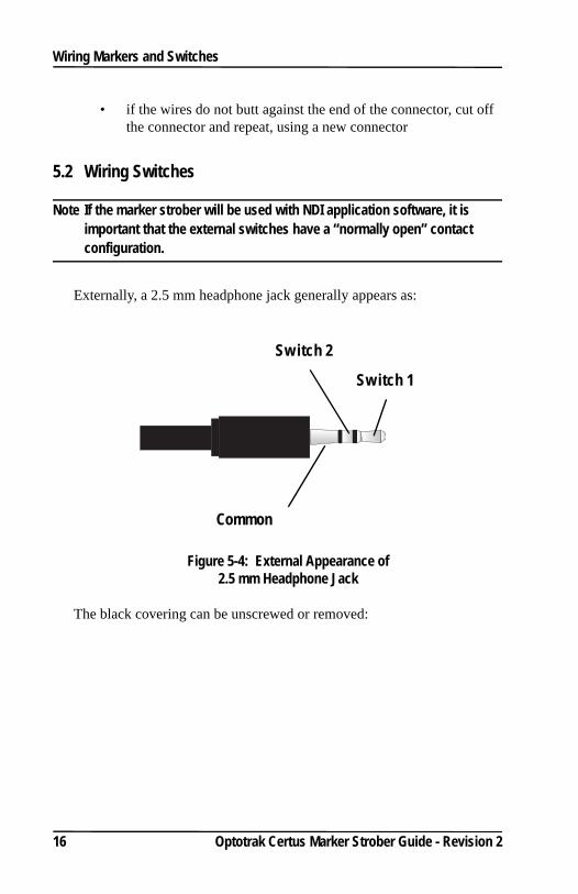
Externally, a 2.5 mm headphone jack generally appears as:
Figure 5-4: External Appearance of 2.5 mm Headphone Jack
The black covering can be unscrewed or removed:
Common
Switch 1
Switch 2
16 Optotrak Certus Marker Strober Guide - Revision 2
Wiring Markers and Switches
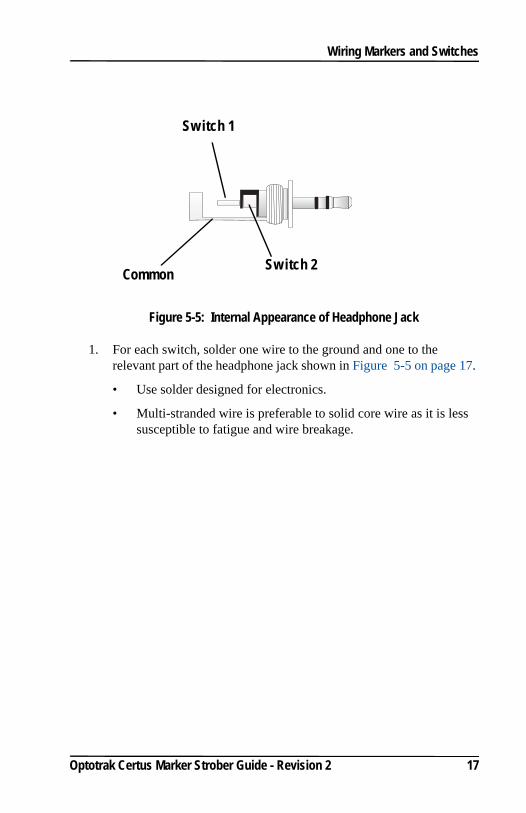
Figure 5-5: Internal Appearance of Headphone Jack
1. For each switch, solder one wire to the ground and one to the relevant part of the headphone jack shown in Figure 5-5 on page 17.
• Use solder designed for electronics.
• Multi-stranded wire is preferable to solid core wire as it is less susceptible to fatigue and wire breakage.
Common Switch 2
Switch 1
Optotrak Certus Marker Strober Guide - Revision 2 17

Abbreviations and Acronyms
18 Optotrak Certus Marker Strober Guide - Revision 2
6 Abbreviations and Acronyms
Abbreviation/Acronym Meaning
BF Patient Isolation (non cardiac)
LED Light Emitting Diode
NDI Northern Digital Inc.
SROM Serial Read Only Memory
Equipment Symbols
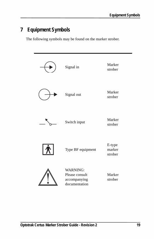
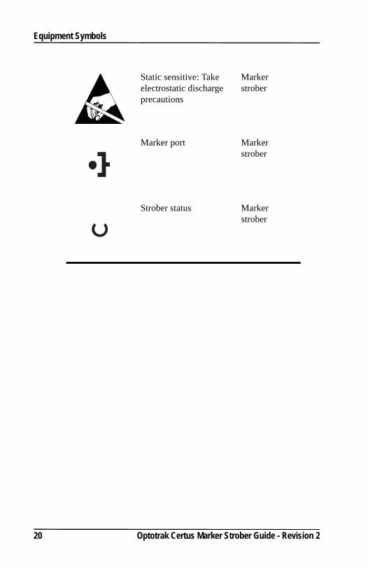
7 Equipment SymbolsThe following symbols may be found on the marker strober.
Signal in Marker strober
Signal out Marker strober
Switch input Marker strober
Type BF equipmentE-type marker strober
WARNING: Please consult accompanying documentation
Marker strober
Optotrak Certus Marker Strober Guide - Revision 2 19
Equipment Symbols
Static sensitive: Take electrostatic discharge precautions
Marker strober
Marker port Marker strober
Strober status Marker strober
20 Optotrak Certus Marker Strober Guide - Revision 2
Index
Optotrak Certus Marker Strober Guide - Revision 2 21
Index
Aactivation order 6Application Programmer’s Interface
3
Hheadphone jack
appearance 16
Mmarker activation
number of 3order of 3
markersnumber to activate 3
Rrigid body
configuring 3
Sstrober activation order 6strober name 3strober status LED 4switches
connecting 16setting number and behaviour
3swivel clip
fastening the tab 9orientation 10removing the strober 11
Ttool activation order 7type BF isolation 5, 8
Wwiring
inserting wire into RJH 14needed equipment 12RJH connector 12switches 16