Embed Size (px)
Citation preview

1. Workpiece Catcher Page 1
Page 4
--
8
.
8
OPTIONAL EQUIPMENT
OPERATING INSTRUCTIONS
2. SwartConveyor
3. Bar Feed Page5
8
8

WORKPIECE CATCHER
-The Workpiece Catcher consists of an air operated catcher arm and a recovery traymounted in the main sliding door.It is sequenced by the 'M' codes M33, M34 and M35.
M33 = Catcher retLirrito Park from Catch Position.
M34 = Catcher to Catch Position.
M35 = Catcher to Eject Position (deposits component into door tray)and return to Park Position.
Programming the Workpiece Catcher
Bring parting blade to Start
N210 G01, X20, FO.15; Part half way or moreN220 G97, S600; Slows spindle to prevent work flting in wrong direction.N230 M34; Work catcher to collect position.N250 GOO,X50.; Rapid clear of work.N260 GOO,X580. Z200 ;N270 M35; Work catcher to eject postion, pause
and return to park position.N280 GOOX580. Z200 ;N290 M99;
Page 1
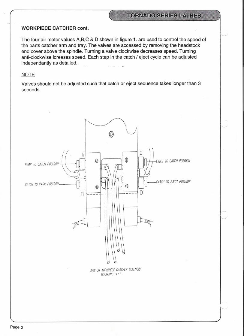
WORKPIECE CATCHER cont.
Th-efour air meter values A,B,C & D shown in figure 1. are used to control the speed ofthe parts catcher arm and tray. The valves are accessed by removing the headstockend cover above the spindle. Turning a valve clockwise decreases speed. Turninganti-clockwise icreases speed. Each step in the catch / eject cycle can be adjustedindependantly as detailed.
NOTE
-
Valves should not be adjusted such that catch or eject sequence takes longer than 3seconds.
PARK TO CA TCH POSITION
CATCH TO PARK PosmON
Page 2
A
B
@
@
@
WEW ON WORKPIECE CA TCHER SOLENOID
MUIJNIIN(; J 'lA 11.
cEJECT TO CA TCH PosmON
CATCH TO EJECT PosmON
D

WORKPIECE CATCHER cont.
In a collision state or if parts catcher fails to finish its sequence within 3 seconds for anyreason, an alarm of 'CATCHER FAULT' No. 1036 appears on screen and the machinestops.
Pressing 'RESET' returnstbe.workpiece catcl1erto its park position and clears thealarm.
Ensure path is unobstructed for catcher arm and tray.Repeat catcher sequence.
If the alarm persists, check the following:-
1. Catch or eject sequence is taking longer than 3 seconds.Adjust air meter valves as necessary.
2. Ensure air supply is present to machine.
3. Check operation of pneumatic cylinder reed switches.
4. Check operation of solenoids & electrical connections.
Page 3

SWARF CONVEYOR (OPTIONAL)
The conveyor is easy to operate having only three controls sited on the conveyor cover.
The buttons are as follows :-
A) Forward
When depressed this gives normal operation modeand the conveyor starts to conveyout of the machine. For safety the conveyor motor is interlocked with the main sliding9-uard and therefore the...g.!!a~d n~~ds to be lock~d befo!~_the QQ.nveyoLc..aO_oPeJ:ate
B) Reverse Jog[) :3 c>o. t. =..i.
This is used to reverse the direction of the conveyor, but will only operate whilst thepushbutton is held in.
C) Stop
This switches off the conveyor.
1--./
1"---,,
".,--........./ '\.
/ \I \I I\ /\ /" ./---
FORWARD REVERSE
Page 4

CLC HYDRAFEED BAR FEED
-Introduction
This section explains the commissioning and operation of the Hydrafeed hydraulic type barfeeder with the Tornado. It should be read in conjunction with the user manual supplied withthe bar feeder. -
Performing and Testing the Electrical Connection to the Lathe
Refer to the electrical schematic diagram, (Drawing No. C1-077-001)
1. If these are not fitted already, install the 24 pole socket and circuit breaker assemblyin the lathe electrical cabinet according to the figure. (See Drawing No. C1-076-002at the end of this section).
2. Plug the 24 pin plug on the bar feeder cable into the socket at the bottom of the righthand wall of the electrical cabinet. Makesure the two hinged clamps are applied to theplug.
3. Prove the continuity of inputs and outputs as follows:-
i. 3 phase to bar feederOn the Hydrafeed, switch on the main isolator and on the control panel, selectMANUAL and pushthe RETRACTbutton. Confirm that the hydraulic pump runs.
If not:
check the circuit breaker, Q9, on the left hand wall of the lathe electrical cabinet.The black button should be depressed to switch the circuit breaker on.
Similarly, check the circuit breaker, A1, in the Hydrafeed electrical cabinet.
If these two are correct, the continuity of the 3 phase connections to the pumpmotor requires checking.
ii. Inputs from bar feederFirstly, configure the lathe software for the Hydrafeed:
Set the CNC Diagnostics D301.0 = 1Set the CNC Diagnostics D301.1 = 0Set the CNC Diagnostics D301.2 = 0 }
Leave all other bits of thisDiagnostic asthe factory setting.
BAR READY input - Diagnostic X6.3Select AUTO on the bar feeder and confirm that the indicators Nos.1 and 6illuminate. Confirm CNC diagnostics X6.3 = 1
If not, continuity of wire No. 228 from bar feeder terminal 7 to plug X17, pin 9, onthe lathe main pcb requires tracing.
Page 5

.10fo - I- .a /is: cJ!r£t,d'VI,c 1A;./' rtJ! &! " ~? /' IJ;)/} ~v ( " ,
~rn ~ /V HARTlNGi' cc XI MAINTFRMINAlS 24 PIN CONNFCTDRft: I XI IN Uo1HF ON Uo1HF. I!I: - - 1 1
~ ,+ 29. t 1- ~(R)2 + JO '2 1 'S\
!.U - +"!I 50 OR60 Hz101o. J &, -JI (J) 1 ~
(T)
~; - ..~a 1---1-. - 1
~r OPTIONSUB-ASSEMBLY r+- + -PE _(SHf!:!.4 J - ~FF[fER
~~::o g A826-1706A -= -Ir' ~ l KtTAGE
Q.O" I II' -
- .- I -EJ.IER~ STOP I t24V/~"" 97 (2J)~ 1> (2J)R£UY /" "'VIEMDVEliNK 1-- -I- - - .~ - - - - -k:- "5J - - (24)~_- -'- 1 (24)
-L ~4 (A) I 9--1 --av -r \ : II I
BARREOUESTL- \"/ 415 (10)1 . I~ (
~ ~-------' Ir ~ ~,...J.-. Rt
(2~f 11p. (IS)'-- - - - - j (4) 'T' FEED1I I I1 '
SS :? 24(AR) I- ,-:a ~ I I~ +24 (C) I I
10 L ,:::J I II!\ ~ r r
~i (5F +24C (13)1- . 1 (6)~~ I~:::s
!t
I
a~ I I~~ X6.1
=q46) 214 (17)
~2 BAREND [' -
~~::j X6.J (9' 228 I~i:~ BAR READY / (15) -C5~~~ ~ I I kC'd
~~~ 24 (CR) 11 I p'" .9£'1;""
~ ~/ I" I:).: I tAa.. .g f
~~ ;-'
~~ 1 . I
~ I V L' " (t'e . I:x! I I
N co II
~ I!::! 0 I I-.D Q 1
~ z PCB. AJ IN I ATI-IE I1 I1
1
lA TI-IEElECTRICALCABINETOr/KZ) I~
I ~ ~I ~ :I
ill,r 0.-~ ':raonx:Q.
!5t\) 0. Q... -\1\ Q
+ (J)
+(7)IIIIIII1
IIIIIIL B~~ FmJ[R
., ------- --
w >
N
BAR fEED£R
-DEJ/ERGENCYS1DP
~~--: _1£00-R0-.. I AUTrJ~ ~ D£TECT
Cl
')
o
--

CLC HYDRAFEED BAR FEED cont.
-END OF BAR input - diagnostic X6.1Select MAN on the bar feeder, depress the FORWARD button and wait forindicator No. 2 to illuminate. Confirm CNC diagnostic X6.1 = 1 as long asindicator No. 2 is on.
If not, continuiti6f wire No. 214ftofn bar feeder terminal 3 to plug X17, pin 6, onthe lathe main pcb requires tracing.
iii. FEED REQUEST output from lathe - Diagnostic Y50.5Confirm the setting of Diagnostic D301 as above.Select AUTO onthe bar feeder andconfirm Indicators 1and 6 are illuminated butnot Indicator 2, (End of bar).
In MDI mode, programme:
M90 (bar mode on)INPUTCYCLE START
.
M86 (bar feed request on)INPUTCYCLE START
Confirm that Diagnostic Y50.5 = 1 (Bar feed output)
Confirm that the bar feeder pump starts running; end of bar should shortly occurand switch the pump into reverse.
If the pump fails to start trace the continuity of :
wire No. 415 from bar feeder terminal 5 to plug X20, pin i-;wire No. 416 from bar feeder terminal 4 to plug X20, pin 2;on the lathe main pcb.
This completes the connection and test procedure.
When testing is over, programme:
M87 (bar feed request off)INPUTCYCLE .START
Page 7

CLC HYDRAFEED BAR FEED cont.'---
Operation of the Lathe with the HydrafeedTO SWITCH THE CNC BAR FEED MODE ON AND OFFThe bar feed mode of operation is available only if Diagnostic No. 301 has been set asabove.
To switch bar feed mode on command the'M- code M90 in either MDI or AUTO mode. Thiscommand is retained by the CNC while the,electrical supply:,is off so if bar feed mode isalways required, switch it on in MDI Mode and then leave it permanently set.
If use of the lathe regularly changes from bar feed use to non bar feed use, it may be moreconvenient to include an M90 command at the head of any part programme written for feeduse. At the end of the programme, include the M-code, M91, to switch the bar feed modeoff again.
Bar feed mode enables the response to the End of Bar signal from the bar feeder and thetwo additional M - codes:
'--"'-- ,
M86 Request Feed OnM87 Request feed Off
M86 must be command at the head of any programme using the Hydrafeed in orderto switchon the hydraulic pump in the bar feeder.
END OF BARUpon receipt ofthis signal from the barfeederthe CNC enters the CYCLE HOLD state. (Seethe Section, Operator's Control Panel Functions, inthe Operating Instructions) At the sametime, the message, END OF BAR, appears on the CRT screen.
If the optional flashing beacon is fitted, this illuminates also.
As described in the Hydrafeed user manual, the bar feeder pumpautomatically reverses fora preset time to retract the push rod.Select JOG MODE on the CNC and load new bar as per the Hydrafeed user manual.
The message on the CNC screen can be cancelled by the MESSAGE RESET button.Select AUTO MODE and start the programme again.
ProblemsBAR FEEDER NOT READY -messageIf this message appears, first confirm that the Hydrafeed is readywith its selector switch inthe AUTO position and with the indicators 1 and 6 illuminated.
If the above are correct, the input BAR READY is disconnected. The continuity of wire No.228 from bar feeder terminal 7 to plug X17, pin 9, on the lathe main pcb requires tracing.
BAR FEEDER PUMP NOT RUNNINGCheck if the circuit breaker, 09, in the lathe or A1 in the bar feeder has tripped and resetas appropriate. IfA1trips repeatedly with or without 09 tripping, there is a fault in the pumpor its motor. If 09 trips repeatedly, but not A1,there is a fault in the connection of the motorsupply wiring between the lathe and the bar feeder.
Page 8

CLC FEEDMASTER BAR FEED
-'ntroduction
This section explains the commissioning and operation of the Feedmaster pneumatic typebar feeder with the Tornado. It should be read in conjunction with the user manual suppliedwith the bar feeder.
Performing and Testing the Electrical Connection to the Lathe
Refer to the electrical schematic diagram, (Drawing No. C1-078-001)
1. If this is not fitted already, install the 24 pole socket assembly in the lathe electricalcabinet according to the figure. (See Drawing No. C1-076-002 at the end of thissection).Plug the 24 pin plug on the bar feeder cable into the socket at the bottom of the righthand wall of the electrical cabinet. Makesure the two hingedclamps are applied to theplug.
2.
3. Prove the continuity of inputs and outputs as follows:-
i. Input from bar feederFirstly, configure the lathe software for the Feedmaster:
Set the CNC Diagnostics 0301.0 = 0
}Leave all other bits of this
Set the CNC Diagnostics D301.1 = 1 Diagnosticas the factory setting.Set the CNC Diagnostics D301.2 = 0
END OF BAR input - Diagnostic X6.1With no air supplyconnectedto the bar feeder,confirmCNC diagnosticsX6.1 = 1
...--
If not, continuity of wire No. 214 from barfeederterminal3to plug X17, pin 6, onthe lathe main pcb requires tracing.
ii. FEED REQUEST output from lathe - Diagnostic Y50.5Confirm the setting of Diagnostic 0301 as above.
Follow the instructions in the Feedmaster manual to set the bar feeder ready tofeed bar with the bar positionedthrough an open collet. Position a bar stop a fewmillimetres clear of the bar end.
Close the lathe guard and in MOl Mode programme:
M90 (bar mode on)INPUTCYLCE START
Page 9

0)
cq t.. ~~ 0c:. ()-I>. -t.. zc:.1.11 0:... 0c:. ~. Cl)<01.11
I"'l o CD() »
()=rCl)nAa.
1 1------------I II I
-I II I
I 1 1
t ~~ - (SHELLi-- - - - - -+ 71 1 1 -
l I I 11 I I 1
EMER~~:frSTOP 1 +24V. 97 (23) 1 ~- - - - - ~(8)RELAY I
) REMOVE LINK I I --DI 4 91 I " (9). -,
r=r 1 ./ (24); ~ .
-L +24 (A) A3-X20 1 1
OV , I 1 1
(3) L +24 (7) I 1 (6)--=: c-- - - --
1
1
(10) 1 V~ >._-
1 I1 I
(16)t-~ 1I
I1
1
1
1
(13) I V
4~1
(17)1 'if~---
I(15) I V(-
I1
1
1
1
1
I
1
I
II
LATHEELECTRICALCABINET(MK2) I~
~
o
N
MAIN TERMINALS
-)(1--IN LA THE
BAR FEEDERCONTROLVOLTAGE
BAR FEEDEREMERGENCYSTOP
U1
1
1
-K16 (1) 1~-I1
(2) I~-I1
1
IA3-X17
1
(5) 1
--<-I1
(6) I
~:24 (CR) I
III
PCB.A3 IN LATHE I~ J
0)Y50.5BAR REQUESTFEED
415
'0'FEEDSOLENOID
416
---L
24 (AR)
+24 (C)
L (10)
(1)
+24C
EOB
MANUALCOLLETENABLE
co
214
~ (3)
~ (12)I1
I1
III1
I1
1
L BA,:!EEDER- - - - - - - -
X6.1BAR ENDX6.3BAR READY
228ID
~N

CLC FEEDMASTER BAR FEED cont.
M86 (bar feed request on)INPUTCYCLE START
Confirm that the-bar feeder.feeds the bar up~othe stop.
If not, confirm that the REQUEST FEED output, Diagnostic Y50.5, = 1.
If this = 0, check ~hatthe END OF BAR input, X6.1, = O.
If this = 1, check the set up of the bar feeder to remove the End of Bar state.
If Y50.5 = 1, trace the continuity of :
wire No. 415 from bar feeder terminal 5 to plug X20, pin 1;wire No. 416 from bar feeder terminal 4 to pluQ.X20,pin 2;on the lathe main pcb.
This completes the connection and test procedure.
When testing is over, programme:
M8? (bar feed request off)INPUTCYCLE START
Operation of the Lathe with the Feedmaster
TO SWITCH THE CNC BAR FEED MODE ON AND OFFThe bar feed mode of operation is available only if Diagnostic No. 301 has been set asabove.
,',",. To'switch bar feed mode on commandtheM '"code M90 in either MOl or AUTO mode. Thiscommand is retained by the CNC while the electrical supply is off so if bar feed mode isalways required, switch it on in MOl Mode and then leave it permanently set.
If use of the lathe regularly from bar feed useto non barfeed use, it may be more convenientto include an M90 command at the head of any part programmewritten for feed use. At theend of the programme, include the M -code, M91, to switch the bar feed mode off again.
Bar feed mode enables the response to the End of Bar signal from the bar feeder and thetwo additional M - codes:
M86 Request Feed OnM8? Request feed Off
M86 must be command at the head of any programme using the Feedmaster in order toswitch on the air supply in the bar feeder.
Page 11

CLC FEEDMASTER BAR FEED cont.
END OF BARUpon receipt of this signal from the barfeederthe CNC enters the CYCLE HOLD state. (Seethe Section, Operator's Control Panel Functions, in the Operating Instructions) At the sametime, the message, END OF BAR, appears on the CRT screen.
If the optional flashing beacon-is fitted, this.illuminates also.
As described in the Feedmaster user manual, the bar feeder main ON/OFF valveautomatically switches off and pressure in the feed tube is exhausted.
Select JOG MODE on the CNC and load new bar as per the Feedmaster user manual.
The message on the CNC screen can be cancelled by the MESSAGE RESET button.Select AUTO MODE and start the programme again.
ProblemsBAR FEEDER NOT RUNNING
i. Check the air pressure to the bar feeder.
ii Check the electrical connections between the bar feeder and the lathe as in thecommissioning instructions above.
CLC MULTIFEED BAR FEED
Introduction
This section explains the commissioning and operation of the Multifeed magazinepneumatic type bar feeder with the Tornado. It should be read in conjunction with the usermanual supplied with the bar feeder.
ADDITIONAL BLOCK SKIPThe interface operation and part programme technique described below require theinstallation in the CNC of the Fanuc software option:
OPTIONAL BLOCK SKIP ADDITIONFANUC PART No. A02B - 0098 - J869
Refer to 600 Lathes Service Department for further information.
Performing and Testing the Electrical Connection to the Lathe
Refer to the electrical schematic diagram, (Drawing No. C1-072-003)
1. If these are not fitted already, install the 24 pole socket and circuit breaker assemblyin the lathe electrical cabinet according to the figure. (See Drawing No. C1-076-002at the end of this section).
Page 12

2. Plug the 24 pin plug on the bar feeder cable into the socket at the bottom of the righthand wall of the electrical cabinet. Makesure the two hingedclamps are applied to theplug.-
3. In the bar feeder electrical control cabinet, check the transformer primary voltagesetting and change this to 415v if necessary.
4. Prove the continuity of inputs and outputs as follows:-
i. 2 supply phase to bar feederOn the Multifeed, switch on the main isolator and on the control panel, confirmthat the red Power ON indicator is illuminated.
If not:
Check the circuit breaker,Q9, on the left handwall of the lathe electrical cabinet.The black button should be depressed to switch the circuit breaker on.
If this is correct, the continuity of the 2 phase connections from the lathe to thetransformer in the bar feeder require checking.
ii. Inputs from the bar feederFirstly, configure the lathe software for the Multifeed:
Set the CNC Diagnostics D301.0 = 0
} Leave all other bits of this
Set the CNC Diagnostics D301.1 = 0 Diagnosticasthe factory setting.Set the CNC Diagnostics D301.2 = 1
BAR READY input - Diagnostic X6.3With reference to the manualsupplied with the Multifeed, arrange the bar feederwith bar in the channel and the magazine, close the safety guard and selectAUTO.
In the bar feeder electrical cabinet, observe the red indicators on the programmable. logic controllerand identifythat designated"Y12".Confirmthat this is illuminated.On the lathe, confirm CNC Diagnostic X6.3 = 1.
If not, continuity of wire No. 228 from bar feeder terminal 15 to plug X17, pin 9,on the lathe main pcb requires tracing.
END OF BAR input - Diagnostic X6.1Set up the bar feeder as above for BAR READY but slide the END OF BAR sensorback such that it is clear of the end of the bar. Close the guard and select AUTO onthe bar feeder.
Observe that the bar feeder indicator, "Y13" is illuminated. On the lathe, confirm thatDiagnostic X6.1 = 1.
Page 13

U1
HART/NG
24 PIN CONNECTORON LA THE
I
29 (1) F- ~30 (2) F- cpm
X ~ WI - I1
I --- l ., I :
OPT/ON SUB-ASSEMBL Y + - --<->-_PE - (SHELL4-- - - - - -I. -AB26-1706A -f I T I r 1
J I I 1-I I II I I
~ 97 (23)1 1 (23)")REMOVELINK ~-- - - --&v 91 (24)1f------
III
(4) t 1 (4)1
(5) f-- - - - --1> (5)I II I
(6) I
?i(B) 1
I
III
(9) ~
IIII
(11)bIIII
(13)b1
(15) I~-1
(17)1~-1
(19) I~- J(14) 1~- I
212 (12) I- C-I II II I
PCB.AJ INLATHE I I~ I
LA THE ELECTRICAL CABINET (MK2) I~
J:
------09 - - - - - I-,-
Ea2.5-4A I
-rl II I
x-"":'I
XlI
1 ~-
2~3~
('):rCl)(')A
0.-
,LA THE I +24V
EMERGENCYSTOP I-RELAY L.
Ir- - --\.--- II II I
OV I A3-X17
(1) t~ (2) ':I1
=A3-X20
Q(8) I,
Y50.2
BAR -K18 IRELOAD :~._C~-b
II
(10) I
Y50.0 L PBARFEED ~ (9) !.ENABLE .~'
I(6) I
Y50.3 L PCOLLET ~9 (5) !.OPEN .~-
I=A3-XI7
I
+24C I~- I(9) IX6.3
BAR READYX6.1BAR END
X6.2BAR RELOADFINISHEDX6.0BAR FAULT
X16.7BAR PUSHER
-
c~-(3) I
J(7) I.
-
o (') CD
MAIN TERMINALSXl IN LA THE
I
ISOLATOR
.-rI
=f'~ .
TERMINALS ON
BARFEEDER
..400V
BAR FEEDERCONTROLVOLTAGE
0BAR FEEDEREMERGENCYSTOP
95(J1
96 BAR FEEDER- CONTROLCIRCUIT
413M-CODE
BAR FEEDER INPU TSUPPL Y VOLTAGE
417 (9) AUTOENABLE
co411 (11) COLLET
OPEN
OV
<.0
+24C (13)
~~~~~IIII
l~~~D~ - - - - - - --
~
N
228 BARFEEDREADY
214END OF BAR o
213M-FIN
210ALARM
PUSHER MOVEMENTSENSOR(OPT/ONAL)

CLC MUL TIFEED BAR FEED cont.
-If not, continuity of wire No. 214 from bar feeder terminal 17 to plug X17,pin 6,on the lathe main pcb requires tracing.
BAR RELOAD FINISH input - Diagnostic X6.2As it is not possiole to set up theJ5arfeeder to transmit this signal other thanduring full automatic operation, its correct connection can be confirmed only bythe use of an electrical continuity checking instrument. Proceed as follows:
switch off the lathe main isolator.
remove the 24 pole plug from the bar feeder cabinet.
"'""'''''''''''.",., '..;'" . ,,,,,,,,,,,.,..in.the.lathe cabinet, locate;.and,remove,the-plugffiarked-"X17";this is the 15 pin,"'''''''''''''''':'.'O..type'' plug in the bottom'left'quadrantof1he-main pcb:
confirm continuity between pin 12 of this plug and pin 19 of the 24 pole plugat the bar feeder end. Investigate and correct any lack of continuity.
replace the plugs and switch the lathe on again.
BAR FAULT input - Diagnostic X6.0Remove all material from the bar feeder to produce an alarm condition.
In the bar feeder electrical cabinet, observe the red indicators on theprogrammable logic controller and identify that designated "Y11". Confirm thatthis is illuminated.On the lathe, confirm CNC Diagnostic X6.0 = 1.
If not, continuity of wire No. 210 from bar feeder terminal 14 to plug X17, pin 3,on the lathe main pcb requires tracing.
iv) Outputs from the CNC
COLLET OPEN output from lathe - Diagnostic Y50.3With reference to the manual supplied with the Multifeed, arrange the bar feederwith bar in the channel and the magazine, close the safety guard and selectAUTO. On the lathe,confirmthat the BAR FAULTinput, Diagnostic X6.0 = 0 andthat the BAR READY input, Diagnostic X6.3 = 1.
Confirm the setting of Diagnostic D301 as above.
Page15

CLC MULTIFEED BAR FEED cont.
Write the following test programme and execute this in CNC AUTO MODE:
M90;M78;M02;
(bar mode on)(open chuck)
Confirm that Diagnostic YSO.3= 1 (Collet Open output)
Inthe barfeederelectricalcabinet,observethe red indicatorson theprorammablelogic controller and identify that designated "X17". Confirm that this isilluminated.
If not, continuity of wire No. 411 from bar feeder terminal 11 to plug X20, pin S,on the lathe main pcb requires tracing. I
"" "
BAR RELOAD output - Diagnostic YSO.2Write the following test programme and execute this in CNC AUTO MODE:
M90;M78;M80M02;
(bar mode on)(open chuck)(bar reload)
Confirm that Diagnostic YSO.2= 1 (Bar reload output)
In the bar feeder electrical cabinet, observe the red indicators on theprogrammable logic controller and identify that designated "XO".Confirm thatthis is illuminated.
If not, continuity of wire No.413 from bar feeder terminal 8 to plug X20, pin 7, onthe lathe main pcb requires tracing.
Taking the CNC out of AUTO MODE cancels this signal.
BARFEEDENABLEoutput- DiagnosticYSO.OSet the barfeed such that it is not transmitting fault status; ie. has material in themagazine, and CNC Diagnostic X6.0 is thus = O.
Close the lathe guard and in MOl MODE command
M90 bar mode on
Confirm that diagnostic YSO.O= 1 (Barfeed Enable)
Page 16

CLC MULTIFEED cont.
-In the bar feeder electrical cabinet, observe the red indicators on theprogrammable logic controller and identify that designated "X16". Confirm thatthis is illuminated.
If not, continuity of wire No. 417 from bar feeder terminal 9 to plug X20, pin 9,on the lathe maifipcb requites tracing.
Taking the CNC out of MDI MODE cancels this signal.
This completes the connection and test procedure.
OPERATION OF THE LATHE WITH THE MULTIFEED
TO SWITCH THE CNC BAR FEED MODE ON AND OFFThe bar feed mode of operation is available only if Diagnostic No. 301 has been set asabove. It enables the part of the lathe system which communicates with the bar feeder anddeals with the bar reload sequence as described below.
To switch bar feed mode on, command the M-code M90 in either MDI or AUTO Mode. Thiscommand is retained by the CNC while the electrical supply is off so if bar feed mode isalways required, switch it on in MDI Mode and then leave it permanently set.
If use of the lathe regularly changes from bar feed use to non bar feed use, it may be moreconvenient to include an M90 command at the head of any part programme written for barfeed use. At the end of the programme, include the M-code, M91, to switch bar feed modeoff again.
The lathe and bar feeder combination can be considered to run in one of two modes.
a) "Normal" mode during which machining takes placealternating with the pushing of barthrough the collet.
b) "Bar reload" mode. The magazine recognizes that the end of bar has been reachedand signals the CNC via the END OF BAR signal.
During the NORMAL mode, the CNC will be running a part program which includes colletopen and close commands. These are usedto command the bar feeder to push bar throughthe open collet via the "BAR FEED START/COLLETOPEN" output signal.
The part program will also include blocks which must begin with a BLOCK DELETE-2character thus, "/2". These blocks command the loadingof new bar from the bar magazine.The BLOCK DELETE-2 character is used to determine whether or not these blocks areexecuted.
The occurrence of the END OF BAR input switches off the BLOCK DELETE-2 condition.These blocks are thus obeyed and loading of a new bar proceeds.
Page 17

OPERATION OF THE LATHE WITH THE MUL TIFEED cont.
Details of typjcal blocks required to reload a new bar are as in the sample part programbelow. In this example all these blocks are written as a SUB-ROUTINE which is calledby a block preceded by the "/2" character.
The M80 code which is used to command the reload switches the BLOCK DELETE-2condition on again so that the-reload blocks.-areJgnoreduntil the next occurrence ofEND OF BAR.
The whole sequence is demonstrated in the sample program. At the side of this areshown the conditions of all the signals described above.
This sample program has no practical machining application.
Page 18

.
continued
l- - --- -- -- - -- -- - -
PROGRAMME EXAMPLE - BEFORE END OF BAR OCCURS.INPUT TO L.ATHE OUTPUT TO BAR
BFRDYS BFDALS ENDBAR BFMCFS AUTBAR BFSTRT BFMR
00001 ; ( Main programme nesting to magazine new bar programme ( 9001 ) ) 1 0 0 0 1 0 0
G10 PO Z-123.456 ( Set workshift to Known data) 1 0 0 0 1 0 0
G92 82000 ( Max Speed) 1 0 0 0 1 0 0
M51 ( Barfeed continuous cycle) 1 0 0 0 1 0 0
M98 P9006 ( Toolchange position) 1 0 0 0 1 0 0
T0100; 1 0 0 0 1 0 0
GO G40 G95 G96 8150 X28 Z-10 T0101 M4; 1 0 0 0 1 0 0
M8; 1 0 0 0 1 0 0
M34; ( PartCatch) 1 0 0 0 1 0 0
G1 X-2 F.08 ( Partoff ) 1 0 0 0 1 0 0
GOX28 1 0 0 0 1 I 0 0
M98 P9006 ( Toolchange position) 1 0 0 0 1 0 0
M35; ( Part discharge) 1 0 0 0 1 0 0
T0102 ( Tool offset for Bar stop) 1 0 0 0 1 0 0
/2 M98 P90001; ( Special block delete/2 for next bar length) 1 0 0 0 1 0 0
GOXOZ3 1 0 0 0 1 0 0
G1 G94 Z-9 F2000 ( Position stop to bar end) 1 0 0 0 1 , 0 0I
N100 M78 ( Return point from magazine sub-routine) 1 0 0 0 1 . 1 0
G4X3 1 0 0 0 1 1 0
ZO.5 (Zero position+ stock) 1 0 0 0 1 1 0
M79 1 0 0 0 1 0 0
M98 P9006 1 0 0 0 1 0 0
T0200 1 0 0 0 1 0 0
NORMAL RUNNING MACHINING PROGRAMME 1 0 0 0 1 0 0
: 11 1 0 0 0 1 0 011 1 0 0 0 1 0 011 1 0 0 0 1 0 0
.11 1 0 0 0 1 0 0
.11 1 0 0 0 1 0 0
.11 1 0 0 0 1 0 0,11 1 0 0 0 1 0 0,
M98 P9006 ( Finaltoolchangepositionto endprogramme) 1 0 0 0 1 0 0
/M52 ( End continuous cycle with block delete disabled) 1 0 0 0 1 0 0
M30 1 0 0 0 1 0 0
% 1 0 0 0 1 0 0

.
( ]
SIGNAL STATES
( ( Jntinued
PROGRAMME EXAMPLE END OF BAR OCCURS.INPUT TO LATHE OUTPUTTO BAR-
BFRDYS BFDALS ENDBAR BFMCFS AUTBAR BFSTRT BFMR00001 ; ( Main programme nesting to magazine new bar programme (9001 ) ) 1 0 0 0 1 0 0G10 PO Z-123.456 ( Set workshift to Known data) 1 0 0 0 1 0 0G9252000 ( Max Speed) 1 0 0 0 1 0 0M51 ( Barfeed continuous cycle) 1 0 0 0 1 0 0M98 P9006 ( Toolchange position) 1 0 0 0 1 0 0T0100; 1 0 0 0 1 0 0GO G40 G95 G96 5150 X28 Z-10 T0101 M4; 1 0 0 0 1 0 0M8; 1 0 0 0 1 0 0M34; ( PartCatch) 1 0 0 0 1 0 0G1 X-2 F.08 ( Partoff ) 1 0 0 0 1 0 0GOX28 1 0 0 0 1 ! 0 0M98 P9006 ( Toolchange position) 1 0 0 0 1 0 0M35; ( Part discharge) 1 0 0 0 1 0 0T0102 ( Tool offset for Bar stop) 1 0 0 0 1 0 0/2 M98 P90001; ( Special block delete/2 for next bar length) 1 0 0 0 1 0 0GO XO Z3 1 0 0 0 1 . 0 0,G1 G94 Z-9 F2000 ( Positionstopto barend) 1 0 0 0 1 0 0N100 M78 ( Return point from magazine sub-routine) 1 0 0 0 1 I 1 0G4X3 1 0 0 0 1 1 0ZO.5 ( Zero position + stock) 1 0 1 0 1 1 0M79 1 0 1 0 1 0 0M98 P9006 1 0 1 0 1 0 0T0200 1 0 1 0 1 0 0
NORMAL RUNNING MACHINING PROGRAMME 1 0 1 0 1 0 0" 1 0 1 0 1 0 0" 1 0 1 0 1 0 0," 1 0 1 0 1 0 0,"
1 0 1 0 1 0 0,"
1 0 1 0 1 0 0,"
1 0 1 0 1 0 0,"
1 0 1 0 1 0 0,M98 P9006 ( Finaltoolchangepositionto endprogramme) 1 0 1 0 1 0 0/M52 ( End continuous cycle with block delete disabled) 1 0 1 0 1 0 0M30 1 0 1 0 1 0 0% 1 0 1 0 1 0 0

.
continued
, ,
PROGRAMME EXAMPLEINPUT TO LATHE OUTPUTTO BAR- FOLLOWING END OF BAR
BFRDYS BFDALS ENDBAR BFMCFS AUTBAR BFSTRT BFMR00001 ; ( Main programme nesting to magazine new bar programme ( 9001 ) ) 1 0 1 0 1 0 0G10 PO Z-123.456 ( Set workshift to Known data) 1 0 1 0 1 0 0G9282000 ( Max Speed) 1 0 1 0 1 0 0M51 ( Barfeed continuous cycle) 1 0 1 0 1 0 0M98 P9006 ( Toolchange position) 1 0 1 0 1 0 0T0100; 1 0 1 0 1 0 0GO G40 G95 G96 8150 X28 Z-10 T0101 M4; 1 0 1 0 1 0 0M8; 1 0 1 0 1 0 0M34; ( PartCatch) 1 0 1 0 1 0 0G1 X-2 F.08 ( Partoff ) 1 0 1 0 1 0 0GOX28 1 0 1 0 1 ; 0 0M98 P9006 ( Toolchange position) 1 0 1 0 1 0 0M35; ( Partdischarge) 1 0 1 0 1 0 0T0102 ( Tool offset for Bar stop) 1 0 1 0 1 0 0/2 M98 P90001; ( Special block delete/2 for next bar length)GO XO Z3
G1 G94 Z-9 F2000 ( Positionstopto barend)N100 M78 ( Return point from magazine sub-routine) 1 0 0 0 1 . 1 0G4X3 1 0 0 0 1 1 0ZO.5 ( Zero position + stock) 1 0 0 0 1 1 0M79 1 0 0 0 1 0 0M98 P9006 1 0 0 0 1 0 0T0200 1 0 0 0 1 0 0. NORMAL RUNNING MACHINING PROGRAMME 1 0 0 0 1 0 0
11 1 0 0 0 1 0 011 1 0 0 0 1 0 011 1 0 0 0 1 0 0.11 1 0 0 0 1 0 0,11
1 0 0 0 1 0 0,11
1 0 0 0 1 0 0,11
1 0 0 0 1 0 0.
M98 P9006 ( Finaltoolchangepositionto endprogramme) 1 0 0 0 1 0 0/M52 ( End continuous cycle with block delete disabled) 1 0 0 0 1 0 0M30 1 0 0 0 1 0 0% 1 0 0 0 1 0 0

.
SIGNAL STATES
( ( (
PROGRAMME EXAMPLE - SUB PROGRAMMESINPUT TO LATHE OUTPUT TO BAR
BFRDYS BFDALS ENDBAR BFMCFS AUTBAR BFSTRT BFMR09001 ( MagazineEjecVReloadProgramme)M79 1 0 1 0 1 0 0GOU300 W200 1 0 1 0 1 0 0M78 1 0 1 0 1 1 0M80 1 0 1 1 1 1 1G4X2 1 0 1 0 1 1 0XOZ3 1 0 1 0 1 1 0G1 G94 Z-9 F2000 . 1 0 1 0 1 1 0M80 1 0 0 1 1 1 1G4 X15 1 0 0 0 1 1 0M99 P100 1 0 0 0 1 1 1 0
General Toolchange Subroutine :- .I
09006 ( Toolchange Position) 1 0 0 0 1. 0 0
M9; 1 0 0 0 1 0 0GO G40 X400 W200 TO; 1 0 0 0 1 0 0M99 1 0 0 0 1 0 0% 1 0 0 0 1 0 0

OPERATION OF THE LATHE WITH THE MULTIFEED cont.
- PROBLEMS
BAR FEEDER NOT READY messageIf this message appears, first check that the Multifeed is in a read state; Le.. in AUTOwith bar in the channel and the magazine.--. ~ . - .
If the bar feeder appears to be alright, a check on the correct transmission and receipt ofthe BAR FEEDER READY signal will have to be performed as described in the sectionabove on testing the electrical connection to the lathe.
BARFEED ALARM - Alarm No. 1038The Multifeed has transmitted a fault status signal to the lathe. The primary cause of this
.:.;isthe, exhaustion of bar stock in the magazine;,.ltmay also be caused by obstruction of the. forwardmovementofthe InsertPusheror of the retractmovementof the MainPusheror
some obstruction in the new bar loading area.
FAILS TO JUMP TO BAR RELOAD SUB-ROUTINEThis sub-routine jump is triggered by the receipt of the END OF BAR signal from theMultifeed. Firstly, confirm its correct transmission by the bar feeder and receipt by the latheas described in the above electrical connection section, under END OF BAR input.
If this signal is being received, confirm that the Fanuc Optional Block Skip Addition has beeninstalled as described at the beginning of this section and that the part programme includesthe Block Skip character, "/2", in the sub-routine jump command as described in theoperation instructions above.
Further, if the part programme does not follow the outline example given above, ensurethat there is at least one block of part programme between the chuck open command andthe sub routine jump block starting with the "/2" command.
Otherwise, if the END OF BAR signal is received during bar feeding subsequent to thechuck open command, it will be too late for it to switch off Block Delete 2. The "/2" com-mand will thus still be active and the sub routine jump will be ignored.
A "dummy" End of Block character is sufficient, thus:
M78,
/2 M98 P90001
MAGAZINE FAILS TO RELOADReload on the Multifeed is triggered bythe receiptofthe BAR RELOADsignal from the lathe.Firstly, confirm its correct transmission by the lathe and receipt by the bar feeder asdescribed in the above electrical connection section, under BAR RELOAD output.
As explained in the operation instructions above, ensure that the part programme isarranged such that upon receipt of an END OF BAR signal, an M80 command (bar reload)is executed. It is this which causes the transmission of the BAR RELOAD output.
Page23

Heckmond"ike,2
B
c
)
E
F'
c
HAll DIMENSIONS
600 LATHES LIMITED
IN
E
CABLE 1
CABLE2F
XJJCh.k'd e 15.11.95
NTSDrown R. PRIES T Scale
CABLEJ FinishHeatTreotm't
c
Material
CastinQ No
MilLIMETRES 85308 Lt.TORNADOBAR FEED INT
CONNECTIONDETAILSGenerally Drawn ToTitle
.. 6'00-Yorkshire, England.
3 s
HThis drowill9 II confidential and reproductionor communication of ItI contentl in wholeor port Is "",,,Ibited without written authorityof 600 lothel Ltd.
~
Cl-076-002Port No....,.-5 A3
3 4 5 6 7 8
-$ )---E3-DO NOT SCALE - f IN DOUBT ASK BREAK ALLS ) CORNERS(0.5 X 450mox) Cl-076. 102
PoriNo.AI 155.\lod. Modification Issue No. Dole
, N£W DRAWING 22.15 /5.11. 95
CABLE 3
FROt.C TO UARKER COLOUR TERU'N TERltN
X17/1 X33/4. . 95 BROv.tl SOLDER STRIP
XI7/2 X33/5 96 PURPLE SOLDER STRIP
XI7/3 X33/14 210 RED SOLDER STRIP
X17/5 X33/13 +24C BlUE SOLDER STRIP
X17/6 X33/17 214 GREEN SOLDER STRIP
X17/7 X33/12 212 YEL SOLDER STRIP
X17/9 X33/15 228 Yt1iITE SOLDER STRIP
X17/12 X33/19 213 , BlACK SOLDER STRIP
Xl7/O.JJ1' SCREEN - - SOLDERSTRIP
CABLEIFROU TO UARKER TERU'N TER....N
XI/29 X33/1 29 STRIP STRIP
XI/JO X33/2 JO STRIP STRIP
XI/31 X33/3 31 STRIP STRIP
XljPE X3J/SHEU - STRIP STRIP
XI/91 X33/24 91 STRIP STRIP
XI/97 X33/23 97 STRIP STRIP
CABLE 2
FROU TO . UARKER JERU'N TERI.i'N
X20/1 X33/10 415 STRIP STRIP
X20/2 X33/16 416 STRIP STRIP
X20/3 .X33/7 +24" STRIP STRIP
X20/5 X33/11 411 STRIP STRIP
X20/6 X20/8 - STRIP STRIP
X20/7 X33/8 413 STRIP STRIP
X20/8 X20/10- STRIP STRIP.
X20/9 X33/9 417 STRIP STRIP
X20/10 X33/6 418 STRIP STRIP
I I I I
..
I 18
-. .
ol. ...
I- lQm". j I
11 11
c
01I [[],
111111 I I I I I ID
II LXJJ