Embed Size (px)
Citation preview

OPTIMIZING THE OPERATING CONDITIONS OF GOLD ELUTION AND
ELECTROWINNING FOR TAU LEKOA STREAM AT KOPANANG GOLD
PLANT
Alfred Lodi Lunga
A research report submitted to the School of Chemical and Metallurgical Engineering, University of the Witwatersrand, Johannesburg, in partial fulfillment of the requirements for the degree of Master of Science in Engineering
Johannesburg, 2006

2
DECLARATION
I declare that this research report is my own work. It is being submitted for the Degree
of Master of Science in Engineering at the University of the Witwatersrand,
Johannesburg. It has not been submitted before for any degree at any other university.
…………………………… 14th day of December 2006

3
ABSTRACT The final gold product of Tau Lekoa mine has a low fineness. This is caused by high concentration
of bases metals in the reefs. Some of these base metals together with gold are leached with cyanide
and are loaded into carbon. If not adequately controlled, they may elute with gold and contaminate
the final product in the electrowinning process.
Based on the understanding of the kinetics of the elution, four parameters, namely temperature, flow
rate, free caustic soda concentration and cyanide strength, were evaluated first for the elution
process. Experimental runs on the plant scale did prove that the first three parameters are the
predominant parameters that maintain base metals in the carbon during the elution and therefore
assist in the improvement of the fineness of the final product. Recommendations were made to
change the operating conditions and the fineness of the gold did improve from 80% to 84 %.
In addition, a thermodynamic model that took to consideration the competition of gold and nickel
was developed for the electrowinning process. This model showed that the deposition of gold and
nickel during the electrowinning was dependant of their concentrations and temperature.
The single pass efficiencies and the deposition rates were also tracked during the experimental.
Based on the finding on the reduction of electrowinning time, the fineness of the final product was
improved from 84% to 85%.
As the refining cost depends on the fineness of gold, the improved fineness means that the gold
content in the bullion is increased and the impurities are decreased, therefore, the refining cost will
decrease as lower penalty costs are charged for the treatment of the bullion with high fineness.
The recommendations of the changes have been implemented permanently and these did show
permanent improvement of the fineness.
.

4
ACKNOWLEDGEMENTS I would like to thank Anglogold Ashanti (Pty) for the financial and logistic support for the
completion of this mini research project. I would like to thank Professor Bryson, my supervisor, for
his guidance and advice.
Especial thanks to Nicole, my wife, to Steven, Jonathan and Abigail, my kids, for the sacrifice they
have endured whenever I was busy with this work.
5
CONTENTS LIST OF FIGURES…………………………………………………….……………7 LIST OF TABLES……………………………………………………………………8 CHAPTER 1 INTRODUCTION…………………………………………………….9 1.1 Background………………………………………………………………………...9
1.2 Problems description……………………………………………………….. ……..9
1.3 Tau Lekoa Elution and Electrowinning process description ……………… ……10
1.4 Zadra process description………………………………………………….. ……12
1.5 Project aims……………………………………………………………………….13
1.6 Organization of the research report..………………………………………………13
CHAPTER 2 LITERATURE REVIEW……………………………………………15 2.1 The chemistry of elution…………………………………………………………15
2.2 The kinetics of gold elution………………………………………………………18
2.3 The electrowinning reactions of gold………………………….…………………19
2.4 The kinetics of gold electrowinning………………………………..…………….20
2.5 Previous work…….………………………………………………………….…...22
CHAPTER 3 EXPERIMENTAL...……………………………………………….…23
3.1 Current operating conditions and equipment sizes of the elution….……….…….23
3.2 Current operating conditions and equipment sizes of the electrowinning………..24
3.3 Samples collections and analysis…………………………………………….........24
3.4 Parameters changed…………………………………………………..…………...25
CHAPTER 4 RESULTS…………………………..……………….……..…………...25
CHAPTER 5 DISCUSSIONS…………………………….….…..…….……………...27
5.1 Influence of temperature……………………………..……………………………27
5.2 Influence of flow rate………………………………..………………………….....27
5.3 Influence of pH……………………………………..………………………..........28
5.4 Influence of cyanide addition in the elution………..…….……………………….28

6CHAPTER 6 MODELLING THE CATHODIC REACTIONS AND EXTRACTION
RATE EVALUATION.............….………………………………..….29
6.1 Cathodic reactions……………………….……………………………………….29
6.2 Single pass analysis and rate deposition…….……………………………………31
CHAPTER 7 CHANGES IN THE OPERATIONS………………………………..34
CONCLUSION……………………………….………………………………………35
REFERENCES……………………………………………………………………….37
APPENDIX…………………………………………………………………………...39
1. Thermodynamics of gold electrowinning…………………………...……………...39
2. Derivation for cathode reactions model…………………………………..………...41
3. Derivation for kinetic model……………………………………………………….42
4. Determination of model parameters………………………………………………..44
5. Data for single pass rate and deposition rate for normal plant practice……………45
6. Data for single pass rate and deposition rate for improved plant practice:
reduction of elution and electrowinning time…………………..………………….46
7. Tables analyzing elements during elution the experiment.………………………..47
7LIST OF FIGURES Figure 1 Elution circuit…………………………………………………………..……….10
Figure 2 Electrowinning circuit…………………………………………………………..11
Figure 3 Zadra elution process……………………………………………………………12
Figure 4 Relation between temperature and elution efficiency…………………………...16
Figure 5 Kinetically and mass transport controlled process………………………………21
Figure 6 Elution and electrowinning circuits with samples points………………………..23
Figure 7 Single pass efficiency and extraction rate……………………………………….31
Figure 8 Single pass efficiency and extraction rate……………………………………….31
Figure 9 Single pass efficiency and deposition rate with extended time………………….32
Figure 10 Single pass efficiency and deposition rate with extended time………………...32
Figure 11 Single pass efficiency and deposition rate with reduced time………………….33

8LIST OF TABLES Table 1 Equilibrium potential of various metals cyanide ions………………………………20
Table 2 Summary of results at different elution flows…………………………………...….25
Table 3 Summary of results with constant flow at reduced caustic concentration……….…26
Table 4 Summary of results with constant flow whilst varying the pH………………….….26
Table 5 Summary of results with constant flow whilst varying the free cyanide strength…..26
Table 6 Equilibriums potential for metals cyanides…………...…………………………….29
Table 7 Optimum operating conditions…………….………………………………………..34

9CHAPTER 1 INTRODUCTION 1.1 Background Tau Lekoa Mine is wholly owned by Anglogold Ashanti and is situated on the Vaal River, North
West Province. The mine produces around 450 kg of gold a month. The ores from the mine are
treated in a separate stream at Kopanang Gold Plant.
The Kopanang Gold Plant is a modern plant that uses mill-leach-CIP- electrowinning processes. The
gold from the electrowinning process is smelted centrally in another plant situated 5 km away from
Kopanang. The quality of the final bullion is affected by the presence of base metals. This project
focuses on the assessment of the existing operating parameters particularly with regards to elution
and electrowinning processes and recommends changes in order to improve the fineness of the
product.
1.2 Problems The reefs from Tau Lekoa underground mines contain low grade gold (2-3 g/t) and they are
characterized by the presence of base metals like nickel, copper, zinc and cobalt. Although the
concentrations of these base metals are very low, they have a negative impact on the downstream
operations.
In order to obtain the required throughput of the plant during the mill stage, more steel balls are
added. The steel consumption is 1 kg per ton of ore. This causes the iron content to increase in the
circuit and get deposited with other base metals in the final product if the elution and electrowinning
processes are not well controlled.
The base metals tend to leach out in cyanide and are loaded on the carbon. Adsorbed base metals in
the CIP can be stripped together with gold in the elution process. Depending on their concentration
in the pregnant solution, cathodic deposition occurs.
Base metals that have not been stripped during the elution will build up in the carbon and will
affect the gold loading in the CIP process.
The continuous decrease of gold content in the stream and the variability of flow rate and
temperature affect the elution and electrowinning processes. Low-grade eluate tends to be
problematic for electrowinning as the impurities tend to “compete “with the gold for deposition
current.

101.3 Tau Lekoa Elution and Electrowinning process description
1.3.1 Elution Circuit
Figure 1 shows a flow sheet of the elution circuit. The elution column operates with a 2-2.5% NaOH
solution with a temperature range of 120oC-135oC. The gold is stripped from the carbon into the
solution. An elution will start when there is 6 ton of loaded carbon in the measuring vessel.
The caustic solution that returns from the electrowinning circuit is pumped into the eluant tanks.
This solution is sent through a primary heat exchanger where the heat from the exiting solution of
the column is used to preheat the entering solution. It is then sent through a steam heater which
raises the temperature to the required range.
The caustic solution is circulated through the elution column. Eluant enters at the bottom and eluate
leaves at the top through the outlet. This pregnant solution goes to the electrowinning where it passes
through the cells. The eluant is pumped to the eluant tanks and from there it is circulated back to the
elution columns.
The process is slow with a residence time of 17-20 hours for satisfactory elution.
2nd heat exchanger
1st heat exchangerElution column
Measuring vessel
Screen
Flash Tank
Eluant Tank
Kiln feed bin
Electrowinning
Adsorption
Electrowinning
Boilers
NaOH top up
2nd heat exchanger
1st heat exchangerElution column
Measuring vessel
Screen
Flash Tank
Eluant Tank
Kiln feed bin
Electrowinning
Adsorption
Electrowinning
Boilers
NaOH top up
Figure 1 Elution circuit

111.3.2 Electrowinning
The electrowinning circuit is shown in Figure 2. The pregnant solution flows from the flash tank to
the electrowinning cells. A current is passed through the cells from a set of rectifiers. The gold is
attracted to the cathodes and electroplates onto it. The cathodes are called baskets and consist of
stainless steel mesh to increase the surface area exposed to the plating process. These baskets are
removed once the plating is done and washed with water under high pressure. The particulate
concentrate is passed to a filter press where it is collected and weighed. Final product is the
concentrate which is stored in bins, which are sealed and dispatched, to the central smelt-house. The
gold barren solution is pumped to the eluant tanks for the next elution.
Elution column 1,2,3
Eluant tank 1,2,3
Rectifier 1,2 Rectifier 3,4Rectifier 5,6
Elution column 1,2,3
Eluant tank 1,2,3
Rectifier 1,2 Rectifier 3,4Rectifier 5,6
Figure 2 Electrowinning circuit
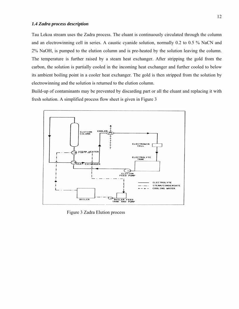
121.4 Zadra process description Tau Lekoa stream uses the Zadra process. The eluant is continuously circulated through the column
and an electrowinning cell in series. A caustic cyanide solution, normally 0.2 to 0.5 % NaCN and
2% NaOH, is pumped to the elution column and is pre-heated by the solution leaving the column.
The temperature is further raised by a steam heat exchanger. After stripping the gold from the
carbon, the solution is partially cooled in the incoming heat exchanger and further cooled to below
its ambient boiling point in a cooler heat exchanger. The gold is then stripped from the solution by
electrowinning and the solution is returned to the elution column.
Build-up of contaminants may be prevented by discarding part or all the eluant and replacing it with
fresh solution. A simplified process flow sheet is given in Figure 3
Figure 3 Zadra Elution process

131.5 Project Aims The specific objectives of the project are to:
• Understand the kinetics of the elution and electrowinning circuits and the impact of different
base metal elements specifically nickel.
• Establish the operating conditions that will improve the fineness of the gold bullion, therefore
reduce its refining cost as it will contain fewer impurities.
• Modeling the gold cathodic reactions and establishment of the operating conditions that will
improve the quality of the final gold product.
1.6 Organization of the research report The first chapter describes the Tau-Lekoa Mines, which is part of Anglogold Ashanti. It introduces
the problems that cause the fineness of final bullion to be low. The quality of gold is contaminated
by base metals that are coming from the ores. This chapter concludes with the description of the
elution and electrowinning processes at the Kopanang Plant. The description of the Zadra process
and the aims of the project are also given in the chapter.
The second chapter reviews the literature on the kinetics and thermodynamics of elution and
electrowinning of gold. It shows how the base metals, if not controlled properly, can affect the final
product. A summary of previous work done is also given.
The third chapter provides the current operating conditions of the elution and electrowinning
circuits. It gives the lists of samples points, the analysis done from Anglogold Laboratory and Rand
Refineries. The results of the test work while varying different parameters are also summarized.
The fourth chapter provides the observations and results of the experimental run at plant scale
followed by the fifth chapter where discussions regarding the results are done. Chapter six will try to
model the cathodic reactions and evaluate the single pass efficiency and the deposition rate during
the electrowinning. Chapter seven will summarized the best operating conditions based on the results
of previous chapters.
A conclusion section will sum up the findings that will allow the plant to operate at optimum
conditions in order to improve the fineness of gold.

14The appendix will summarized the thermodynamics of electrowinning, the detailed development of
models as well as the constants used for the models, data for single pass analysis and deposition rate,
actual plant values regarding the fineness and the analysis of different elements during the test work.

15CHAPTER 2 LITERATURE REVIEW 2.1 The chemistry and factors affecting elution Activated carbon is used to adsorb gold that is leached by cyanide solution. The gold is then stripped
from this loaded carbon by means of elution to form a concentrated eluate which is then processed
for gold recovery by electrowinning. Essentially elution is the reverse of the adsorption process.
Some of the base metals that are contained in the ores are also leached with cyanide and loaded on
the carbon in the CIP process.
Some of the factors that influence the elution are: temperature, flow rate, gold in the eluant, free
NaOH. The washing of loaded carbon with a diluted acid prior to the elution and the decomposition
of cyanide during elution are known to affect the rate of elution under certain condition. The elution
is a slow process that requires from 8 to 96 hours for completion at elevated temperature. This is
primarily due to slow down diffusion of aurocyanide ion within the micropores of the relatively
large particles of activated carbon.
The adsorption-desorption equilibria of gold cyanide on carbon have been described by linear
isotherms (Adams 1986).
The study work of Adams (1990) showed that the adsorption process is thermodynamically
reversible. Therefore the chemical and physical aspects that boost elution will inhibit adsorption and
vice versa.
To understand the mechanism of elution, it is pertinent to understand the favorable conditions for
adsorption and then the reasons why conditions for elution are targeted will become more obvious.
The exact mechanism of gold adsorption is a highly debatable issue. However, it is generally
accepted that the adsorption of (metal) ions from the leach solution by the carbon does not involve
any slow reactions. The slow steps are associated with mass transport in the solution and solid
phases. It is speculated that the rate of elution will be affected by the same processes (Van Deventer
et al, 1993).
Gold adsorption occurs as a result of the formation of the metal cyanoaurate anion as given by
Adams(1989):
Mn+(aq) + nAu (CN)-
(aq) = M(n+) [Au(CN)-2]n(ads)
Mn+ = K+, Na+, Ca2+
The degree of gold adsorption on carbon is strongly dependant on the nature and concentration of the
alkaline metal cation present in the adsorption medium. Monovalent alkaline metal gold complexes

16are less strongly adsorbed than divalent alkali metal gold complexes and thus logically the
monovalent complex would be easier to elute from carbon. Thus, the preferred species for the
aurocyanide complex before elution takes place would be Na+ or K+ forms (Van der Merwe et al,
1991).
The presence of calcium carbonate has only a passivating effect on the rate of adsorption and does
not effect the equilibrium capacity of the carbon to adsorb gold, thus suggesting that this passivation
effect is purely physical (Van Deventer et al, 1993).
Adsorption is strongly dependant on the pH value of the adsorption medium, the amount of gold
adsorbed in the pH range 4 to 7 being almost twice the amount that is adsorbed in the pH range 8 to
12. It should be noted that carbon’s selectivity for gold appears to increases with increase in pH and
free cyanide concentration. This is probably because at high pH (>10) most other metal cations have
precipitated as metal hydroxides.
Creating the opposite physical conditions needed for adsorption is almost the ideal condition for
eluting the gold from the carbon. Van Deventer et al (1993) summarize the most important
parameters that influence the rate of elution, in order of importance they are as follows: temperature,
the concentration of cyanide and caustic and the ionic strength of the eluant or strip solution, water
quality and acid treatment. Steyn (2003) however recognized there is a plateau on the relationship
between the temperature and elution efficiency, and he provided the curve as given below
8 0
8 5
9 0
9 5
1 0 0
9 5 1 0 0 1 0 5 1 1 0 1 1 5 1 2 0 1 2 5 1 3 0E l u t i o n T e m p e r a t u r e
% S
tripp
ing
Effic
ienc
y
Figure 4 Relation between temperature and elution efficiency

17While temperature plays perhaps the most significant role in gold elution, the parameters affecting
this are interrelated to some extent, thus making their evaluation and definition somewhat complex.
The adsorption of gold onto activated carbon is an exothermic reaction and an increase in
temperature will shift the equilibrium in favor of desorption. High temperature necessitates also the
presence of cyanide to prevent the formation of AuCN, which is difficult to desorb (Stanley, 1987).
If calcium dicyanoaurate is present, it is converted to less strongly adsorbed sodium aurocyanate due
to the high concentration of sodium in the eluant.
Ca [Au (CN)2]2 + 2 Na + = Ca 2+ + 2 NaAu (CN)2
At reduced temperature and low concentrations of gold (to achieve low levels of eluted carbon
grades) and calcium ions in the fresh strip solution, the ion further dissociates to:
NaAu (CN)2 = Na + + Au(CN)-
In his thesis, Banini (1993) confirms that gold is adsorbed as Au (CN)-2 ion pair. He continues by
stating that for elution to be favored, it demands that the solution have a low concentration of
spectator ions like K+, Na+ and Ca2+, hence low ionic strength.
The deleterious effect of free cyanide on the adsorption of the aurocyanide complex is believed to be
related to competitive non-specific adsorption and this effect becomes more pronounced if the
temperatures are increased. Hence, a high free cyanide is often used to drive the desorption of gold
from the carbon reaction. It is also thought that cyanide is necessary for faster elution rates and that
it promotes more “complete” elution of gold from carbon (Van Deventer et al, 1993).
Increasing the concentration of cyanide or caustic to too high level will start to have deleterious
effects on the elution rate. The high ionic strength of the eluant will start to counteract the positive
benefits of these reagents, as well as lead to wastage of the reagents and production inefficiencies.
It is reported by Adams (1989) that cold acid washing results in the limited formation of an AuCN
type species, the reactions being considerably more marked when hot washing is employed. From
gold elution point of view, the AuCN formed is very difficult to elute. Van Deventer et al (1993)
have shown that after the acid washing steps, only 50% of the loaded gold on the carbon can be
desorbed by regional water. To convert the AuCN formed into a state that is amenable to elution,
presoaking is employed. Presoaking converts the AuCN to Au (CN)-2 which is easily eluted with
good regional water.
Apart from the removal of calcium, zinc and nickel which influence gold elution, acid washing has
an effect on the adsorption process. Without acid washing poor adsorption may be encountered.
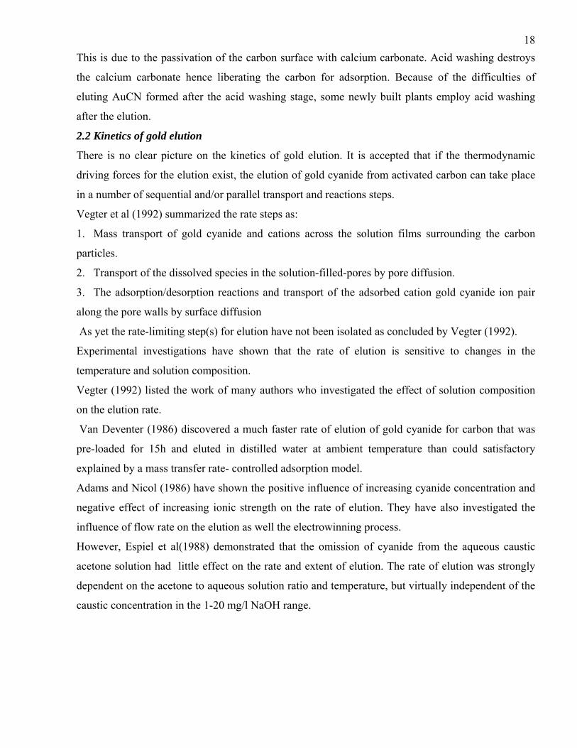
18This is due to the passivation of the carbon surface with calcium carbonate. Acid washing destroys
the calcium carbonate hence liberating the carbon for adsorption. Because of the difficulties of
eluting AuCN formed after the acid washing stage, some newly built plants employ acid washing
after the elution.
2.2 Kinetics of gold elution
There is no clear picture on the kinetics of gold elution. It is accepted that if the thermodynamic
driving forces for the elution exist, the elution of gold cyanide from activated carbon can take place
in a number of sequential and/or parallel transport and reactions steps.
Vegter et al (1992) summarized the rate steps as:
1. Mass transport of gold cyanide and cations across the solution films surrounding the carbon
particles.
2. Transport of the dissolved species in the solution-filled-pores by pore diffusion.
3. The adsorption/desorption reactions and transport of the adsorbed cation gold cyanide ion pair
along the pore walls by surface diffusion
As yet the rate-limiting step(s) for elution have not been isolated as concluded by Vegter (1992).
Experimental investigations have shown that the rate of elution is sensitive to changes in the
temperature and solution composition.
Vegter (1992) listed the work of many authors who investigated the effect of solution composition
on the elution rate.
Van Deventer (1986) discovered a much faster rate of elution of gold cyanide for carbon that was
pre-loaded for 15h and eluted in distilled water at ambient temperature than could satisfactory
explained by a mass transfer rate- controlled adsorption model.
Adams and Nicol (1986) have shown the positive influence of increasing cyanide concentration and
negative effect of increasing ionic strength on the rate of elution. They have also investigated the
influence of flow rate on the elution as well the electrowinning process.
However, Espiel et al(1988) demonstrated that the omission of cyanide from the aqueous caustic
acetone solution had little effect on the rate and extent of elution. The rate of elution was strongly
dependent on the acetone to aqueous solution ratio and temperature, but virtually independent of the
caustic concentration in the 1-20 mg/l NaOH range.

192.3 Electrochemical reactions of gold electrowinning The following electrochemical reactions are of relevance during the gold electrowinning process as
described by Barbosa et al (2001):
Au(CN)-2 + e- = Au + 2CN- (1)
E = -0.6 + 0.059*log [Au (CN) 2] – 0.118 log [CN-]
O2 + 2H2O + 4 e- = 4 OH- (2)
2 H2O + 2e- = H2 + 2OH- (3)
E = -0.4 – 0.059 log [OH-]
2 H2O = 4 H+ + O2 + 4 e- (4)
E = -0.83 – 0.059 log [OH-]
2OH- + CN- = CNO- + H2O + 2 e- (5)
E = -0.97-0.0295log [CN-] + 0.0295 log [CNO-]- 0.059 log [OH-]
Where E represents the electrode potential required for the reaction to occur and the squares
brackets, the species activities in solution.
The gold, which is present in the solution in the form of aurodicyanide [Au (CN)2-], is reduced to
metallic gold, according to the equation (1).
Reaction (2), representing oxygen reduction in alkaline solutions, is one of the main cathodic
reactions competing with gold deposition and consumes a significant fraction of the available current
flowing to the cathode, as the electrolyte is likely to be saturated with oxygen due to the oxygen
evolution occurring at the anode.
Reaction (3) represents the hydrogen evolution that commences at a potential of -1.2 V (SCE). The
evolution of hydrogen is under kinetic control at all potentials within the bed and therefore consumes
a high proportion of the cathodic current.
The major anodic reaction is the oxidation of water to oxygen as described by reaction (4),
accompanied by the kinetically slower oxidation of cyanide to cyanate as given by reaction (5)
Cyanide can also be oxidized in bulk solution by dissolved oxygen.
Other metals like silver, copper, nickel and iron will also from complexes with cyanide.
The relevance of some of these metals will be studied in this project.

20Steyn (2003) provides the equilibrium potentials for the reduction of various metals cyanide ions as
given in Table 1
Reactions N Eaq, (V) (SHE)
Pb(CN)42- Pb + 2e-
2 -0.38
Ag(CN)2- Ag + e-
1 -0.45
Au(CN)2- Au + e-
1 -0.63
Cu(CN)32- Cu + e-
1 -0.75
Fe (CN)64- Fe +2e-
2 -0.99
Ni (CN)42- Ni + 2e-
2 -1.07
Table 1: Equilibrium potentials for metal cyanides From Table 1, it is evident that lead and silver will thermodynamically plate out preferentially to
gold since the reduction potentials of these metal-cyanide complexes are more positive than that of
the reduction of the aurodicyanide ion.
Note that thermodynamics only gives an indication of the species that will be most stable but, it does
not state anything about the kinetics or the rate of the reactions. It may therefore be possible that
although a specie can be thermodynamically stable under certain conditions, it may be kinetically
unfavorable to achieve this stability due to very slow reaction rates which will lead to impractical
retentions times. Therefore a study of the kinetic appears important.
2.4 The kinetics of gold electrowinning The rate determining steps of the electrowinning reaction is characterized the rate at which gold is
deposited onto the cathode surface. The reaction is either kinetically controlled or mass transport
controlled.
The kinetically controlled reaction implies that the rate of reaction of reduction of aurocyanide to
solid gold at the cathode surface is slower than the rate of the diffusion of aurodicyanide ions across
the boundary layer to the cathode surface.
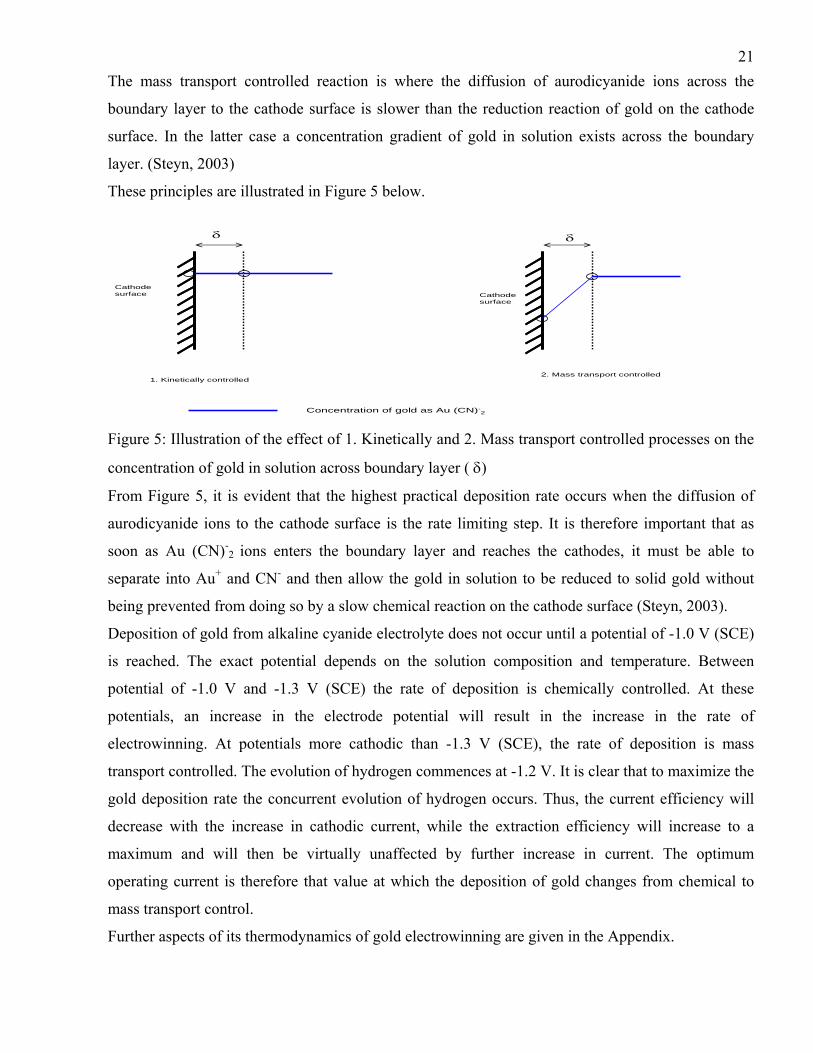
21The mass transport controlled reaction is where the diffusion of aurodicyanide ions across the
boundary layer to the cathode surface is slower than the reduction reaction of gold on the cathode
surface. In the latter case a concentration gradient of gold in solution exists across the boundary
layer. (Steyn, 2003)
These principles are illustrated in Figure 5 below.
δ δ
Cathode surface Cathode
surface
1. Kinetically controlled2. Mass transport controlled
Concentration of gold as Au (CN)-2
Figure 5: Illustration of the effect of 1. Kinetically and 2. Mass transport controlled processes on the
concentration of gold in solution across boundary layer ( δ)
From Figure 5, it is evident that the highest practical deposition rate occurs when the diffusion of
aurodicyanide ions to the cathode surface is the rate limiting step. It is therefore important that as
soon as Au (CN)-2 ions enters the boundary layer and reaches the cathodes, it must be able to
separate into Au+ and CN- and then allow the gold in solution to be reduced to solid gold without
being prevented from doing so by a slow chemical reaction on the cathode surface (Steyn, 2003).
Deposition of gold from alkaline cyanide electrolyte does not occur until a potential of -1.0 V (SCE)
is reached. The exact potential depends on the solution composition and temperature. Between
potential of -1.0 V and -1.3 V (SCE) the rate of deposition is chemically controlled. At these
potentials, an increase in the electrode potential will result in the increase in the rate of
electrowinning. At potentials more cathodic than -1.3 V (SCE), the rate of deposition is mass
transport controlled. The evolution of hydrogen commences at -1.2 V. It is clear that to maximize the
gold deposition rate the concurrent evolution of hydrogen occurs. Thus, the current efficiency will
decrease with the increase in cathodic current, while the extraction efficiency will increase to a
maximum and will then be virtually unaffected by further increase in current. The optimum
operating current is therefore that value at which the deposition of gold changes from chemical to
mass transport control.
Further aspects of its thermodynamics of gold electrowinning are given in the Appendix.
222.5 Previous work on the effects of base metals Not as much has been written on the impact of base metals on elution and electrowinning.
Fisher and Labrooy (1997) have assessed the impact of nickel in leach, electrowinning and elution.
They discuss the competitive adsorption of gold and nickel cyanides onto activated carbon and
investigate the changes in solution parameters that may improve gold adsorption and/ or inhibit
nickel adsorption. In addition, they discuss the selective removal of nickel from carbon by acid
washing, prior to gold elution by means of different physical and chemical conditions. They also
recommend a change in the cyanide content in the eluate to keep the nickel out of solution during
electrowinning.
23CHAPTER 3 EXPERIMENTAL 3.1. Current operating conditions and equipment sizes of the elution
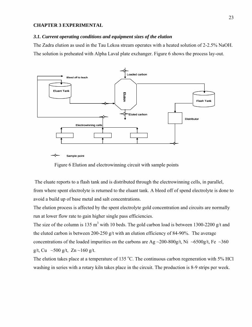
The Zadra elution as used in the Tau Lekoa stream operates with a heated solution of 2-2.5% NaOH.
The solution is preheated with Alpha Laval plate exchanger. Figure 6 shows the process lay-out.
Bleed off to leach
Elution
Flash Tank
Distributor
Eluant Tank
Electrowinning cells
Loaded carbon
Eluted carbon
Sample point
Bleed off to leach
Elution
Flash Tank
Distributor
Eluant Tank
Electrowinning cells
Loaded carbon
Eluted carbon
Sample point
Figure 6 Elution and electrowinning circuit with sample points
The eluate reports to a flash tank and is distributed through the electrowinning cells, in parallel,
from where spent electrolyte is returned to the eluant tank. A bleed off of spend electrolyte is done to
avoid a build up of base metal and salt concentrations.
The elution process is affected by the spent electrolyte gold concentration and circuits are normally
run at lower flow rate to gain higher single pass efficiencies.
The size of the column is 135 m3 with 10 beds. The gold carbon load is between 1300-2200 g/t and
the eluted carbon is between 200-250 g/t with an elution efficiency of 84-90%. The average
concentrations of the loaded impurities on the carbons are Ag ~200-800g/t, Ni ~6500g/t, Fe ~360
g/t, Cu ~500 g/t, Zn ~160 g/t.
The elution takes place at a temperature of 135 oC. The continuous carbon regeneration with 5% HCl
washing in series with a rotary kiln takes place in the circuit. The production is 8-9 strips per week.

243.2 Current operating conditions and equipment sizes of the electrowinning
The electrowinning cells are continuously supplied with electrolyte, except when there is a strip. The
flow sheet is given in Figure 6.
The circuit possesses 6 electrowinning cells in series and each cell contains 8 cathodes and 9 anodes.
They are contained within a rubber-lined stainless steel box. The applied potential difference is 10 V
and the applied current varies between 600-620 A. The electrowinning circuit operates for 48 hour
and the temperature of the eluate entering the circuit is controlled at 80-85 oC. The average
electrowinning production is between 0.6 to 1 kg per cathode.
3.3. Sample collection and analysis
Samples were collected in the plant at the elution columns at specific points as indicated by star(*)
and the final bullion is be sampled at Rand Refineries. The initial test work was run from May 2006
up to August 2006. The last test work was run in November 2006 for the electrowinning section.
The samples for loaded carbon, eluted carbon, eluate and eluate solutions were collected during the
experiments. The analyses of base metals, silver and gold were done in the solution samples (eluate
and eluant) and the same analyses were done for the solids samples (loaded and eluted carbons).
The above analyses were done whilst varying the elution flow, temperature and caustic soda
strength.
Operational data like the inlet and outlet elution temperatures and pH as well the free caustic
strength were recorded. The elution time was kept constant at 18 hour during the experiment.
All samples were analyzed in the Vaal River Laboratory, Anglogold. Gold bullion sampling and
analysis was done at Rand Refineries, Johannesburg.
3.3 Parameters changed
Three elution flows rate were tested at 25, 30 and 35 m3/ h , the elution temperatures as well the
strength of the free NaOH were also changed during the tests. The operating conditions as described
above were recorded and the elution efficiency of different elements were calculated whilst the
fineness of gold was evaluated. The results of the experiment are given in the next chapter.

25CHAPTER 4 RESULTS
From the experiments run on the plant scale, four major findings could be highlighted:
o Excellent finenesses are achieved in the temperature range of 120-125 ºC
o Nickel content in the loaded and eluted carbon are high
o Zinc and Cobalt did not elute during the elution
o Change in cyanide strength did not improve the fineness of gold
The Appendix 7 summarizes the data collected in the plant as well as the fineness of gold in the
bullion
Three different flows were tested during the elution and elution efficiencies were calculated for gold,
silver and the impurities. Table 2 summarizes those results are given below.
o Copper had a high elution rate
o Poor finenesses were achieved when the elution of Ni and Cu took place at 25 m3/ h
o Silver elution efficiency was related to the flow
o Cobalt and Zinc do not elute
o The flow of 35 m3/ h showed low elution efficiency of gold but the flow 25 m3/ h showed poor
fineness of gold and better elution efficiency
o Best flow was 30 m3/ h with regard to elution efficiency and fineness of gold
Elution flow (m3/h) 25 30 35Average Au elution efficiency (%) 85 84 70Average Ag elution efficiency (%) 81 78 68Average Ni elution efficiency (%) 27 11 12Average Cu elution efficiency (%) 90 90 82Average Zn elution efficiency (%) 0 1 0Average Co elution efficiency (%) 0 0 0Fineness 73 80 76 Table 2 Elution efficiencies at different flow rates
As the temperature reaches a plateau around 120-125 ºC regarding the elution efficiency as given on
page 16, it was decided to run the experiment in this range of temperature and utilize the flow of 30
m3/ h and vary the free NaOH concentration.
The results achieved are summarized in Table 3. While comparing these results with Table 2, the
following observations were made:
o Improvement of fineness of gold by 3%
o Improvement of elution efficiency of gold by 1.5%

26o Improvement of elution efficiency of silver by 3%
o Decrease in elution efficiency of nickel and copper
Elution flow (m3/h) 30Temperature (ºC) 120-125Average Au elution efficiency (%) 87Average Ag elution efficiency (%) 82Average Ni elution efficiency (%) 5Average Cu elution efficiency (%) 72Fineness 84 Table 3 Elution efficiency with reduced NaOH
The concentration of free caustic could not be reduced below 1.5 % as the current did become
unstable and fluctuated severely below 600 A. The resulting deposition of gold was poor.
Another test was run at a flow rate of 30 m3/ h and temperature range of 120-125 ºC whilst the pH
was varying. The results are summarized in Table 4 and the following observations can be made:
o Low fineness are achieved at high pH
o Elution efficiency for copper and nickel increased
pH 11..12 12…13 >13Average Au elution efficiency (%) 85 84 70Average Ag elution efficiency (%) 81 78 68Average Ni elution efficiency (%) 8 9 23Average Cu elution efficiency (%) 80 82 90Fineness 80 84 81 Table 4 Elution efficiency whilst varying the pH
The last test was run by varying the cyanide strength whilst keeping the pH, the temperature and
flow rate constant at the best operating conditions. The results are summarized in Table 5. It was
observed that the fineness of gold did not improved when comparing the results with Table 3. Free cyanide (%) 0.05 0.70 0.10Average Au elution efficiency (%) 85 84 85Average Ag elution efficiency (%) 82 83 81Average Ni elution efficiency (%) 11 9 10Average Cu elution efficiency (%) 80 79 77Fineness 84 83 84
Table 5 Elution efficiency whilst varying the free cyanide
The discussions regarding the observations and results are given in the next chapter.

27CHAPTER 5 DISCUSSION ON THE ELUTION SECTION 5.1. Influence of temperature Temperature is probably the variable that has the greatest effect on the elution rate. As was
previously stated, the adsorption and elution rates are both adversely affected by the variation of
temperature.
The test run showed that the best elution was achieved when the temperature was between 120 - 125oC.
This finding is confirmed by the graph supplied by Steyn (2003) where he showed the effect of
temperature on stripping efficiency. This result confirmed the fact that the elution is an endothermic
process i.e. an increase in temperature will benefit the process. The increase of temperature has to be
limited as it can favor the formation AuCN. As it is known, AuCN can slow down the elution. This is seen
when the temperature reaches 130oC when no increase in the efficiency will be expected, as showed by
Figure 3. It can also be said that an increase in temperature above 125oC is a waste of energy.
5.2 Influence of flow rate Adams and Nicol (1986) stated that the overall rate of elution is influenced by the flow rate and they
have developed a model that links the elution efficiency to the flow rate.
However, Van Deventer et al (1993) reported that elution efficiency is independent of the flow rate
in the range 1 to 5 bed volumes (BV) per hour if the length to diameter ratio is 10 or more.
At Kopanang, this parameter is above 10, which means that the flow rate will have an impact on the
elution efficiency. From the test work, it has been confirmed that the flow rate has an impact on the
efficiency of elution and the quality of the final product.
High flow rate (35m3/h) showed low elution efficiency although the fineness was better compared to
low flow rate (25m3/h). It has also been observed that low fineness was achieved when the flow was
reduced to 25 m3/h as the elution of nickel and copper was very high. The effect of flow rate is
probably related to the fact that channeling of the strip solution takes place through the carbon bed.
Obviously, down flow column, as applied in the plant is more susceptible to channeling of the
elution solutions and hence the effect of flows rate appear to be more critical.
The flow rate of 30 m3/h seems to give reasonable results in terms of elution efficiencies and gold
fineness as summarized in Table 2.

28The low flow rate (25 m3/h) provides more residence time is achieved in the column, therefore more
elution of gold and base metals, especially copper and nickel will take place. Although the elution
efficiency is improved, the increase in base metal affects the fineness of the final gold.
The high flow rate (35 m3/h) during elution can assist with more elutions per cycle with an adverse
effect on the stripping efficiency. A high flow rate limits the elution of base metals but will provide
low elution efficiency as the residence time in the column is reduced.
The high flow rate appears to short circuit the columns and therefore the elution appears to be not
completed.
The observation that comes from experience is that the elution is a more diffusion controlled
mechanism. This was confirmed by Deventer et al (1993). However, high flow rate had a negative
impact on the overall efficiency of the electrowinning process as predicted by Adams and Nicol
(1986)
5.3 Influence of pH The reduction of pH seems to improve the elution of gold. This was probably enhanced by the fact
that the test work was run in the temperature range of 120 - 125oC. It appears that the base metals
did have a low (poor) elution rate at lower pH. This is observed in Table 3. It appears that the low
caustic strength had the effect of keeping the base metals in the carbon. Although the gold fineness
did improve, it is expected that the downstream process (electrowinning) is affected as it requires
high pH to favor gold deposition as given by the Pourbaix diagram in Figure 4.
5.4 Influence of cyanide in elution Another test was run in late August 2006, the main change being the addition of cyanide in the
elution circuit. This test was run by keeping the optimum condition as found in the previous test
work i.e. the temperature range of 120-125 ° C in the elution with a pH close to 11-12 and the flow
rate of 30 m3/ h. It was observed that there is no improvement in the fineness of the final gold by
comparing the fineness. This is in contradiction to the recommendation given by Fisher and Labrooy
(1997). The result seems to be disappointing.
29CHAPTER 6 MODELLING THE CATHODIC REACTIONS AND EXTRACTION RATE
6.1 Cathodic reactions
The feed solution contains mainly gold and silver in solution. This is contaminated by impurities
such nickel, copper and iron that have been eluted. Depending on the operating conditions and their
concentration, these impurities usually co-deposit with the gold and silver in the electrowinning
stage. Therefore it is important to formulate a model containing a set of reactions which includes the
deposition of gold and silver while minimizing the co-deposition of base metals. This model will
derive from the Nernst Equations as basis.
The following reactions, as provided in Chapter 2, are expected to takes place on the cathode:
Au(CN)-2 + e- = Au + 2CN- (1)
2 H2O + 2e- = H2 + 2OH- (2)
O2 + 2H2O + 4 e- = 4 OH- (3)
Mn+ + ne- = M (s) Mn+ : Ni, Cu, Fe (4)
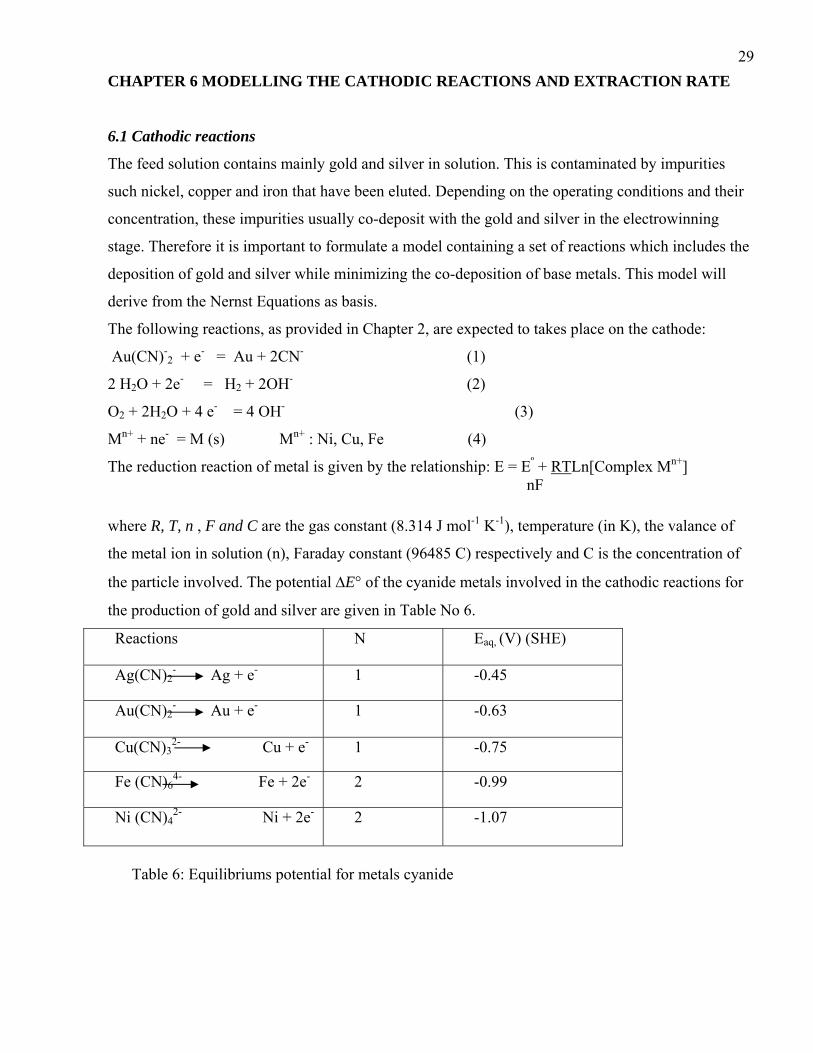
The reduction reaction of metal is given by the relationship: E = Eº + RTLn[Complex Mn+] nF
where R, T, n , F and C are the gas constant (8.314 J mol-1 K-1), temperature (in K), the valance of
the metal ion in solution (n), Faraday constant (96485 C) respectively and C is the concentration of
the particle involved. The potential ΔE° of the cyanide metals involved in the cathodic reactions for
the production of gold and silver are given in Table No 6.
Reactions N Eaq, (V) (SHE)
Ag(CN)2- Ag + e- 1 -0.45
Au(CN)2- Au + e- 1 -0.63
Cu(CN)32- Cu + e- 1 -0.75
Fe (CN)64- Fe + 2e- 2 -0.99
Ni (CN)42- Ni + 2e- 2 -1.07
Table 6: Equilibriums potential for metals cyanide
30Hydrogen evolution starts at a potential of E= 0 and the metal deposition will start at a potential
E= - 0.45 V for silver, E = - 0.63V for gold, E = -0.75 V for copper, E = -0.99 V for iron and E = -
1.07 V for nickel
The Nersnt equation for each metal involved in the cathodic reactions is:
E Ag = E 0Ag + RTLn [Ag(CN)2
-] (1) F E Au = E 0
Au + RTLn [Au(CN)2-] (2)
F E Cu = E 0
Cu + RTLn [Cu(CN)32-] (3)
F E Fe = E 0
Fe + RTLn [Fe (CN)64-] (4)
2F E Ni = E 0
Ni + RTLn [ Ni (CN)42-] (5)
2F By replacing the value of E° of each metal in the equations given above and the multiplying out
different constants with F = 96500, R= 8.314 J mol-1 K-1 , the potentials of the cyanide metals for the
deposition of the metals will be known. The model for the deposition of gold preferentially to nickel
will be given by the equation as E Au > E Ni:
10233 > (Ln [ Ni (CN)42-] - 2 Ln [Au(CN)2
-] ) (6)
T
This relation is limited to the temperature above 75ºC, as any temperature below that will affect the
kinetics of gold deposition.
The derivation model is given in the appendix.
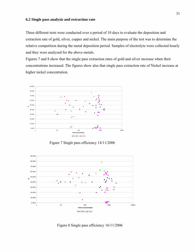
316.2 Single pass analysis and extraction rate
Three different tests were conducted over a period of 10 days to evaluate the deposition and
extraction rate of gold, silver, copper and nickel. The main purpose of the test was to determine the
relative competition during the metal deposition period. Samples of electrolyte were collected hourly
and they were analyzed for the above metals.
Figures 7 and 8 show that the single pass extraction rates of gold and silver increase when their
concentrations increased. The figures show also that single pass extraction rate of Nickel increase at
higher nickel concentration.
0.00%
10.00% 20.00% 30.00% 40.00% 50.00% 60.00% 70.00% 80.00% 90.00%
1 10 100 1000 10000
Feed concentration
%
Au Ni Ag Cu Figure 7 Single pass efficiency 14/11/2006
0.00% 10.00% 20.00% 30.00% 40.00% 50.00% 60.00% 70.00% 80.00% 90.00%
1 10 100 1000 10000 Feed concentration
%
Au Ni Ag Cu
Figure 8 Single pass efficiency 16/11/2006

32Figures 9 and 10 also show their also the extraction rates. These depend on the reduction potential,
where silver has the higher deposition rate than any other metals tracked. Whenever silver is
depleted from solution, gold and copper start depositing in preference to nickel. The nickel
deposition rate starts increasing when silver and copper are depleted in the solution, therefore gold
will start competing with nickel for deposition. This is the confirmation of the model described by
the relation (6) that proves that the deposition of metals depends on their concentration in the
solution. This indicates that the way to solve contamination of the final product is to reduce the
electrowinning time as the nickel deposition rate increases whenever the gold deposition rate
decreases.
0.00%
10.00% 20.00% 30.00% 40.00% 50.00% 60.00% 70.00% 80.00% 90.00%
0 2 4 6 8 10 12 14 16 18
Hour
%
Au Ag Cu Ni Figure 9 Single pass efficiency versus time 14/11/2006
0.00% 10.00% 20.00% 30.00% 40.00% 50.00% 60.00% 70.00% 80.00% 90.00%
0 2 4 6 8 10 12 14 16 18Hour
%
Au Ag Cu Ni Figure 10 Single pass efficiency versus time 16/11/2006

33A special test was run with the elution and electrowinning time reduced from 18hours per cycle to
15 hours per cycle to address the preferential deposition of nickel after the depletion of gold.
This has resulted in an increase of gold fineness from 83.8 % to 85.2%. This reduction of
electrowinning time was adopted on the plant. The single pass efficiency versus time is plotted in
Figure 10.
This Figure shows clearly that the nickel deposition rate was much faster after 8 hours of
electrowinning. This is because of the depletion of silver and copper and the decrease in the
concentration of gold. This is the confirmation of the model given early on in Chapter 6.1.
0.00% 10.00% 20.00% 30.00% 40.00% 50.00% 60.00% 70.00% 80.00% 90.00%
0 2 4 6 8 10 12 14Hour
%
Au Ag Cu Ni Figure 11 Single pass efficiency with short time 27/11/2006

34CHAPTER 7 CHANGES TO THE OPERATING CONDITIONS
7.1 Elution
The experiments run, at plant level, did show that the fineness of gold depend on three parameters.
These parameters are the temperature, the flow rate of the elution, the pH (or the free caustic soda
strength). Although literature advises that an increase in cyanide concentration in the eluate improve
the fineness, the current test work did not show any substantial improvement in the quality of the
final gold when this was tried.
The fineness of gold during the test work increased from 80% to 84 % by operating the plant in the
range of optimum conditions. These optimum operation conditions favor the elution of gold and at
the same time create the conditions that minimize the elution of base metals.
These conditions are summarized in Table 7 below
Temperature (ºC) 120-125Elution flow (m3/h) 30pH 12…13Electrowinning time (Hour) 15 Table 7 Optimum operating conditions
It is also important to note that the operating condition as recommended by Fisher and Labrooy
(1997) did not show the expected results during the plant test work. This might due to the fact the
electrowinning process was not run at the recommended pH. This could be interesting to explore in
the future. The change that is required to run this successfully would be to add cyanide and caustic
after the elution. This will allow to increase the cyanide strength and run the electrowinning at the
recommended pH of 13.
7.2 Electrowinning
The extraction rate during the electrowinning was also monitored and it was found that the
deposition rate of nickel started taking place after 9-10 hours. This was justified as the concentration
of copper and silver were depleted in the electrolyte and the concentration of gold was reduced,
therefore it was suggested to reduce the electrowinning cycle time from 18hours to 15 hours, this did
show an improvement of the fineness by 1 %, bringing the total improvement in the fineness from
80% to 85%.
The benefice of the higher fineness is the reduction of the refining costs as it is reduced due to fewer
impurities that have to be reduced.

35CONCLUSION
This project focused on the elution and electrowinning sections as the base metals contained in the
reefs were leached, loaded and eluted during the leach, the CIP and elution stages. The same base
metals end up in the final gold during the electrowinning process.
Prior to starting the experimental phase, the main focus was to understand the kinetics of the gold
elution and electrowinning processes.
Four parameters were critically evaluated in the elution process namely, the flow rate, the
temperature and the pH (or free caustic soda concentration) and the cyanide concentration. Three of
the four parameters had an impact on the elution process but the most significant ones were the
temperature and the pH.
It was found that running the elution at a temperature of 135 º C did not improve the elution as the
best average temperature range was found to 120 ºC - 125 ºC. Any increase of temperature favors the
formation of AuCN, which is known to slow down the elution efficiency.
The reduction of free caustic from the range of 2-2.5% to 1.5-1.9% also assisted in the improvement
of the fineness as the low caustic strength had an effect of keeping the base metal on the carbon,
especially nickel.
Therefore two parameters were reduced in a range that would favor the elution of gold only and
restrict the elution of the nickel.
The increase of flow rate (35 m3/h) resulted in the deterioration of elution efficiency of gold and
other base metals compared to when flow rate is 30 m3/h. This is due to the shortage of residence
time in the column.
The reduction of flow rate to 25 m3/h did improve the stripping efficiency but this has resulted in the
deterioration of the fineness as more gold and base metals were stripped. The flow rate of 30 m3/h
appears to be the best flow rate for the elution as the elution efficiency and the fineness of gold were
excellent compared to the other two flow rates.
However, some authors like Kar (1995) claims the increase in cyanide concentration improve the
elution efficiencies, but this was found not to be the case in this study.
From these parameters, a new elution operating strategy was implemented. This resulted in the
improvement of the fineness from 80 % to 84 %. It appears clearly that the combination of
temperature range and free caustic concentration are the predominant factors that maintain base
metals on the carbon and assist in the improvement of the fineness.
36On the electrowinning section, a model related to the thermodynamics was formulated. This model
showed clearly that the fineness of gold depends on the concentrations of gold and nickel and on
temperature.
The single pass efficiency and the extraction rate were tracked in the electrowinning. It was found
that during the deposition of gold on the cathode, silver and copper were depleted first and whenever
the concentrations of these metals were reduced in the solution, nickel started to deposit therefore
affecting the quality of the product. The deposition of nickel was time dependant as after 9-10 hours,
its extraction rate increased drastically and the one for gold decreased. It was therefore decided to
reduce the electrowinning time from 18 hours to 15 hours. This resulted in the improvement of the
fineness from 84 % to 85 %.
The advantage of the increased fineness is the reduction of the refining costs as the final bullion does
have lesser impurities. This is due to the relationship between the fineness and the refining costs.

37 REFERENCES Adams, M.D and Nicol, M.J. (1986) The kinetic of the elution of gold from activated carbon. C.E.
Fivaz and R.P. King (Editors), Gold 100, Proceeding, SAIMM, Johannesburg, pp111-121
Adams, M. (1989) Chemistry of the CIP process, PhD Thesis, Wits University, Johannesburg.
Adams, M.D (1990) Kinetics of elution of gold from activated carbons by Zadra methods, Trans
Institution of Mining & Metallurgy, IMM, Vol. 99, pp. C71-79
Banini, G.A., (1993) Modeling of the elution process, Msc thesis, Wits University, Johannesburg.
Barbosa, LAD, Sobral, LGS, Dutra, AJB (2001) Gold electrowinning from diluted cyanide
liquors: Performance evaluation of different reaction systems, Centre for mineral technology-Rio de
Janeiro, Federal University of Rio de Janeiro, RJ, Brazil
Fisher MJ and Labrooy SR (1997) The effect of nickel on gold recovery during adsorption and
elution, World gold conference
Kar, Jugal (1995) Effect of caustic and cyanide level on nickel reduction in stripping circuit,
Randol gold forum, Perth, Australia
Paul, R.L, Filmer, A.O, Nicol, M.J (1983) The recovery of gold from concentrated aurocyanide
solutions. Council for Mineral technology (Mintek), Ranburg, South Africa
Stanley, G. The extractive metallurgy of gold in South Africa, Volume 2, SAIMM monograph series
M7.
Steyn, J. (2003) – Electrowinning optimization, Internal report, Anglogold Ashanti
Van Deventer, JSJ and Van der Merwe, P.F. (1993) Factors influencing the elution of gold from
activated carbon, Department of Metallurgical engineering, University of Stellenbosh, South Africa
Van der Merwe, P.F. (1991), Fundamentals of the elution of gold cyanide from activated carbon,
PhD, University of Stellenbosh

38Vegter, N.M, Van Vuuren C.P.J and Botha A.J (1993) The kinetics of elution of gold cyanide
from activated carbon. Hydrometallurgy: Fundamental, Technology and innovation, TMS, Society
for mining, metallurgy and exploration, Inc, Colorado

39APPENDIX
1. Thermodynamics of gold electrowinning
It is important, from electrowinning point of view, to know which species will be stable at specific
potentials and pH values. Pourbaix introduced the E-pH or Pourbaix diagram on which the dominant
species for a system are indicated as a function of the potential, pH and the ion activity. A typical
Pourbaix diagram for the Au/CN/H2O system is shown in Figure a
Pourbaix Diagram Au/CN/ H2O
The two parallel dotted lines indicate the O2/ H2O line (top dotted line) and H2O/ H2 line (bottom
dotted line). The slope of these line is -0.06 V per pH value implying that the electrode potential for
the reduction of water is 0 at a pH 0 of whereas this value changes to -0.78 V at a pH of 13. The
water or aqueous stability region exists between these two lines which, from Figure 1, indicates that
gold will be in solution as Au (CN)-2
In general, pH values above 13 are used in some Electrowinning cells to minimize corrosion of the
anodes caused by the localized drop in pH due to the reduction of water taking place at the anodes
which produces H+ ions. To plate gold it will be necessary to lower the potential of the cathode to
below that indicated by the lines separating the Au and Au (CN)-2 stability fields.
From Figure 11, it can be seen that when operating at pH values of 13 and conditions as specificied,
a potential more negative than -0.5 V (SHE) need to be applied in order to plate gold.
This can be done as follow:
40In order to plate gold the reduction of aurodicyanide to solid gold needs to occur as discussed in the
half-reaction below: Au (CN)-2 + e- = Au + 2CN-
For electrochemical reaction to take place the resultant electrode potential needs to be positive in
order to obtain a negative Gibbs free energy value.
A negative ΔG value indicates the electrochemical reaction can occur
ΔG= -nFE, where E is the overall reaction potential, F is the Faraday constant and n is the number of
electron transferred.
It is therefore necessary to apply a potential more negative than -0.5 V to acquire a positive overall
potential as explained below:
E resultant = E reduction - E applied = -0.5-(0.6) = 0.1 V
In this case an over potential of 0.1 V was applied.
The size and location of predominance regions is dependant on the concentrations of the different
species involved. Consequently, the electrode potential needed for the plating of a metal will depend
on the cyanide concentration, the concentration of the metal in the solution and the level to which it
must be removed. This can be determined from the Pourbaix diagrams or by using the Nernst
equation: E = E° - (0.059/n)*log (1/[M+]), where n is the number electrons transferred and [M+] is
the concentration of the metal in solution.
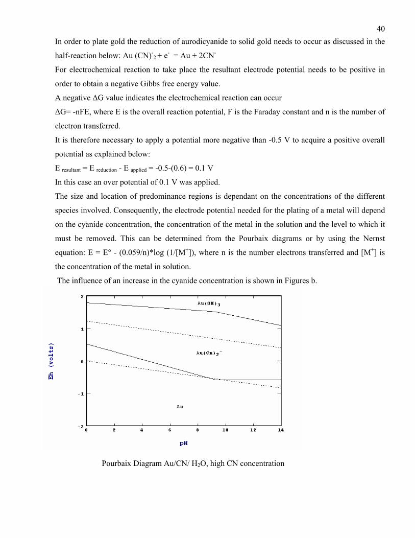
The influence of an increase in the cyanide concentration is shown in Figures b.
Pourbaix Diagram Au/CN/ H2O, high CN concentration
41When comparing Figures 11 and 12, it becomes evident that the increase in the free cyanide
concentration adversely affects the electrowinning process by changing the reduction potential of Au
(CN)-2 to solid gold to more negative values. Typically a potential more negative than -0.65 V needs
to be applied when the cyanide concentration is changed to 0.5 % whereas -0.56 V is required for 0.1
% cyanide.
2. Derivation for the cathodic reaction model
E Ag = -0.45+ 0.000086T Ln [Ag(CN)2-]
E Au = -0.63 + 0.000086T Ln [Au(CN)2
-] E Cu = -0.75 + 0.000086T Ln [Cu(CN)3
2-] E Fe = -0.77 + 0.000043T Ln [Fe (CN)6
4-] E Ni = -1.07+ 0.000043T Ln [ Ni (CN)4
2-]
The silver will be the first to be deposited at any temperature. The impurity copper will start co-
depositing when E Au will be equal or less than E Cu. This will be the same for other impurities.
Due the fact that the concentration of copper and iron are very low in the eluate, it will be advisable
to avoid the nickel to co-depose with other elements. This will be done if the model provides the
following relation: E Au > E Ni
E Au = -0.63 + 0.000086T Ln [Au(CN)2- ] > E Ni = -1.07+ 0.000043TLn [ Ni (CN)4
2- ]
0.44 > 0.000043T (Ln[Ni (CN)42- ] - 2Ln[Au(CN)2
- ] )
10233 > (Ln [ Ni (CN)42-] - 2 Ln [Au(CN)2
-] ) (1)
T
Relation (1) describes the model that co-relates the concentration of nickel and gold and the
temperature of the eluate in the electrowinning. This relation is limited to temperature above 75ºC,
as any temperature below that will affect the kinetics of gold deposition

423. Derivation for kinetic model
This model will correlate the rate of deposition of different species during the electrowinning
process. The following assumptions as made by Paul et al (1983) are:
• There is a plug flow in the cell i.e. that the back-mixing of solution does not occur.
• The cathode material is of uniform porosity and tortuosity
• The deposition rate of electroactive species within the bed is controlled by mass-transport to the
cathode
• There is a steady-state flow in the cell
Paul et al (1983) postulated that the concentration, Ct , of electroactive species at any time, t, after
the start of a multiple-pass electrowinning operations follows the relationship:
Ct = Co exp (-QRt/V) (2)
Where Co is the concentration in time t=0, E is the single pass extraction, t, the time and V is the
volume of the cell.
Stanley (1987) affirmed that the recovery of any species by electrodeposition is measured in terms of
the extraction efficiency E and this is correlated to the concentrations of species by the relations: R =
(Co- Ct)/ Ct (3) where Co and Ct are the concentrations of electroactives species entering and
leaving the electrowinning cells respectively
By replacing the E from (13) to (12), and re-arranging all terms of the relationship, one obtains
Ln Ct + hCtt = Ln Co – Qt/V (4) with h = Q/ Co
After the establishment of the model that correlate the concentration of species at any time t in the
cell, one has to establish the model that correlate the deposition rate during the electrowinning.
Figure No 7 shows the sketch of the process:
C 1 =C 2 …………………………………………………………. C 7 =C8
Q, Cin t C 1 C 2 C 2 C3 C4 C5 C6
R 1 R 2 R8
Q, Cout
Steel wool electrowinning cell
The mass balance of each species entering the cell will go through n = 8 cathodes in the cells with a
constant flow rate Q and Rn the deposition rate for the specific cathode.

43Cin Q = R1 + C1 Q (5)
C1 Q = R2 + C2 Q (6)
C2 Q = R3 + C3 Q (7)
C3 Q = R4 + C4 Q (8)
C4 Q = R5 + C5 Q (9)
C5 Q = R6 + C6 Q (10)
C6 Q = R7 + C7 Q (11)
C7 Q = R8 + Cout Q (12)
By replacing equation (12) in equation (11), one correlates the inlet and outlet in the cathode No8.
By keep on doing the same replacement, one will find the following relations:
C7 Q = R8 + Cout Q (13) C6 Q = R7 + R8 + Cout Q (14) C5 Q = R6 + R7 + R8 + Cout Q (15) C4 Q = R5 + R6 + R7 + R8 + Cout Q (16) C3 Q = R4 + R5 + R6 + R7 + R8 + Cout Q (17) C2 Q = R3 + R4 + R5 + R6 + R7 + R8 + Cout Q (18)
C1 Q = R2 + R3 + R4 + R5 + R6 + R7 + R8 + Cout Q (19)
Cin Q = R1 + R2 + R3 + R4 + R5 + R6 + R7 + R8 + Cout Q (20)
Assuming the Rn = R, relation (20) will be
Cin Q = nR + Cout Q (21)
Stanley (1987) emphasized that the deposition rate R is given by the R = kLACnt (22) where kL is the
mass-transfer coefficient, Ct is the concentration and A is the electrode area of each cathode.
By introducing (22) to (21) and re-arranging the terms, the relationship will become:
Cnt = ( Cin - Cout )*Q / n kLA (33)

44
Both relations (14) and (33) describe the kinetic model of each species of the electrolyte that enter
the cell and provide their concentration and mass- transfer coefficient at any given time.
It is also evident that the increase of the deposition rate depends only on the electrode area.
4 Determination of model parameters
4.1 Flow rate and volume
The flow rate in the electrowinning varies between 25-35 m3/ h, this is equivalent to 6.9- 8.3 l/h and
the cell volume is 1.2 m3.
Barbosa et al (2001) studied the performance evaluation of different reaction systems and have
establish the mass transport coefficient (kL) for gold deposition on a steel wool electrode to be
56*10-6 ms-1
4.2 Calculation of the steel wool area A
The density of the steel wool is ρsteel= 7000 kg/m3 and the radium of the section wire is r = 140 μm.
ρ = m/ π*L*r
m/L = 7000*3.14*(0.00014)2
= 0.000431 m/kg
This equates to (0.000431 kg/m)-1 = 2320 m/kg
With 3 kg of steel wool per cathode, this is equivalent to 2320*3= 6960 m of steel wool wire per
cathode.
The steel wool area A is given by 2*π*L*r = 2*3.14*6960*o.00014 = 6.12 m2

455 Data for single pass rate and deposition rate for normal plant practice
1st test 14/11/2006Au Feed Au Out Ag Feed Ag out Cu Feed Cu Out Ni Feed Ni out Au Ag Cu Ni
1 hour 320 150 389 89 42 41 450 450 53.13% 77.14% 2.38% 0.00%2 hour 450 230 500 161 47 45 550 540 48.89% 67.78% 4.26% 1.82%3 hour 675 250 611 239 46 35 620 615 62.96% 60.91% 23.91% 0.81%4 hour 980 530 200 83 56 42 700 690 45.92% 58.33% 25.00% 1.43%5 hour 1560 910 167 89 38 19 750 730 41.67% 46.67% 50.00% 2.67%6 hour 1490 910 44 28 34 14 990 980 38.93% 37.50% 58.82% 1.01%7 hour 1380 810 11 8 28 11 760 720 41.30% 30.00% 60.71% 5.26%8 hour 1100 540 24 11 870 570 50.91% 54.17% 34.48%9 hour 900 430 22 7 780 510 52.22% 68.18% 34.62%10 hour 630 320 15 5 630 350 49.21% 66.67% 44.44%11 hour 540 360 8 5 870 360 33.33% 37.50% 58.62%12 hour 210 135 910 375 35.71% 58.79%13 hour 110 65 860 320 40.91% 62.79%14 hour 75 30 760 550 60.00% 27.63%15 hour 55 30 810 360 45.45% 55.56%16 hour 25 15 850 250 40.00% 70.59%17 hour 10 7 830 275 30.00% 66.87%
2nd test 16/11/2006Au Feed Au out Ag Feed Ag out Cu Feed Cu Out Ni Feed Ni out Au Ag Cu Ni
1 hour 300 240 494 106 80 75 825 825 20.00% 78.57% 6.25% 0.00%2 hour 450 310 412 153 63 51 790 790 31.11% 62.86% 19.05% 0.00%3 hour 920 430 647 247 76 46 820 810 53.26% 61.82% 39.47% 1.22%4 hour 1345 780 424 153 56 29 970 950 42.01% 63.89% 48.21% 2.06%5 hour 2010 1250 288 124 32 17 850 830 37.81% 57.14% 46.88% 2.35%6 hour 1650 1150 153 73 27 11 720 710 30.30% 52.31% 59.26% 1.39%7 hour 1590 1190 106 65 45 19 690 550 25.16% 38.89% 57.78% 20.29%8 hour 1300 700 41 27 22 10 840 600 46.15% 34.29% 54.55% 28.57%9 hour 1035 550 15 9 910 690 46.86% 40.00% 24.18%10 hour 790 450 8 5 760 450 43.04% 37.50% 40.79%11 hour 710 430 7 4 870 350 39.44% 42.86% 59.77%12 hour 515 390 760 570 24.27% 25.00%13 hour 410 290 870 450 29.27% 48.28%14 hour 200 120 780 350 40.00% 55.13%15 hour 150 70 630 290 53.33% 53.97%16 hour 80 35 650 360 56.25% 44.62%17 hour 25 15 750 320 40.00% 57.33%
10 6 730 310 40.00% 57.53%

46
3rd test 27/11/2006Au Feed Au out Ag Feed Ag out Cu Feed Cu Out Ni Feed Ni out Au Ag Cu Ni
1 hour 550 220 450 120 82 76 620 615 60.00% 73.33% 7.32% 0.81%2 hour 1000 600 380 130 66 52 750 750 40.00% 65.79% 21.21% 0.00%3 hour 1284 940 500 230 77 38 780 760 26.79% 54.00% 50.65% 2.56%4 hour 1350 1160 260 110 52 21 810 800 14.07% 57.69% 59.62% 1.23%5 hour 1600 1270 130 75 36 15 810 740 20.63% 42.31% 58.33% 8.64%6 hour 1340 1040 70 44 22 11 930 870 22.39% 37.14% 50.00% 6.45%7 hour 850 580 20 14 15 8 790 710 31.76% 30.00% 46.67% 10.13%8 hour 750 310 8 3 940 720 58.67% 62.50% 23.40%9 hour 640 230 850 350 64.06% 58.82%10 hou 890 210 53.48% 76.40%11 hou 830 350 73.08% 57.83%12 hou 730 360 67.65% 50.68%13 hou 750 310 70.00% 58.67%14 hou 810 280 58.75% 65.43%15 hou 850 300 62.00% 64.71%
6. Data for single pass rate and deposition rate for improved plant practice: Reduction of
elution time and electrowinning
r 460 214r 390 105r 340 110r 160 48r 80 33r 50 19
47
on (g/t) 850 897 670 780 1060 923 910 910 2150Eluted Carbon (g/t) 150 120 98 150 104 90 115 185 180 140 180 156 178 300 300 270Elution efficiency (%) 82.4 81.8 89.1 83.0 84.5 88.5 76.5 82.5 85.0 84.8 81.2 82.9 80.4 88.0 86.0 91.6
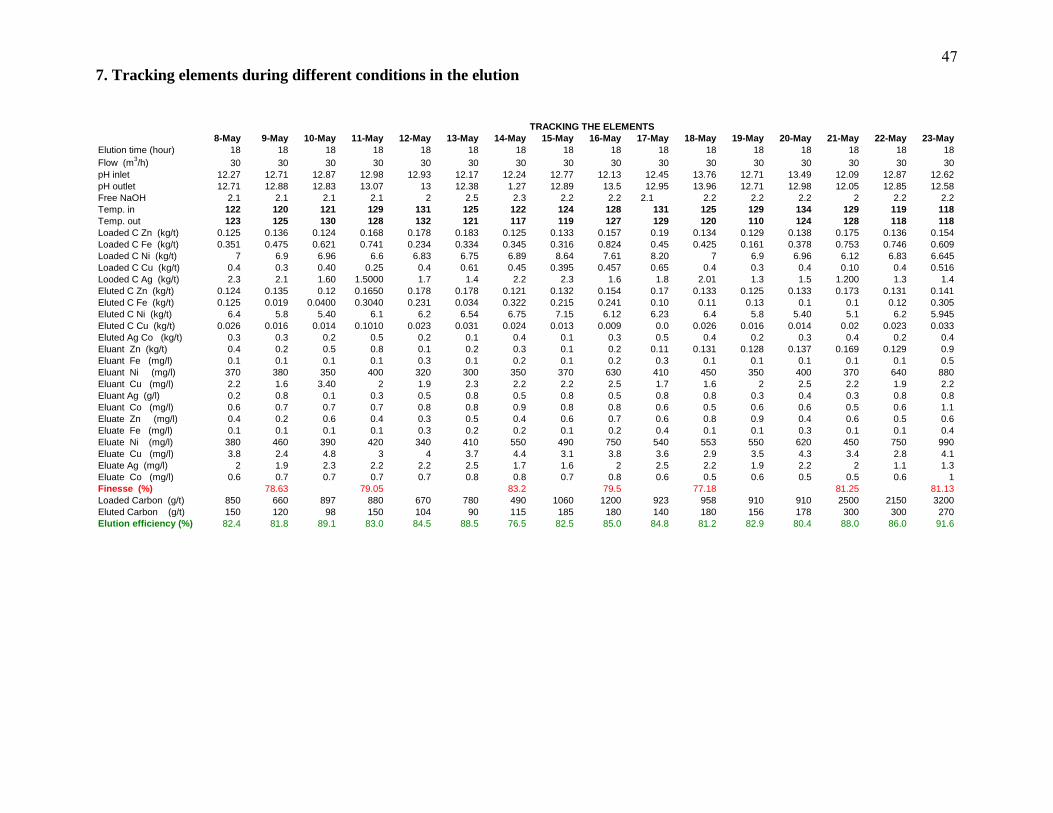
7. Tracking elements during different conditions in the elution
TRACKING THE ELEMENTS8-May 9-May 10-May 11-May 12-May 13-May 14-May 15-May 16-May 17-May 18-May 19-May 20-May 21-May 22-May 23-May
Elution time (hour) 18 18 18 18 18 18 18 18 18 18 18 18 18 18 18 18Flow (m3/h) 30 30 30 30 30 30 30 30 30 30 30 30 30 30 30 30pH inlet 12.27 12.71 12.87 12.98 12.93 12.17 12.24 12.77 12.13 12.45 13.76 12.71 13.49 12.09 12.87 12.62pH outlet 12.71 12.88 12.83 13.07 13 12.38 1.27 12.89 13.5 12.95 13.96 12.71 12.98 12.05 12.85 12.58Free NaOH 2.1 2.1 2.1 2.1 2 2.5 2.3 2.2 2.2 2.1 2.2 2.2 2.2 2 2.2 2.2Temp. in 122 120 121 129 131 125 122 124 128 131 125 129 134 129 119 118Temp. out 123 125 130 128 132 121 117 119 127 129 120 110 124 128 118 118Loaded C Zn (kg/t) 0.125 0.136 0.124 0.168 0.178 0.183 0.125 0.133 0.157 0.19 0.134 0.129 0.138 0.175 0.136 0.154Loaded C Fe (kg/t) 0.351 0.475 0.621 0.741 0.234 0.334 0.345 0.316 0.824 0.45 0.425 0.161 0.378 0.753 0.746 0.609Loaded C Ni (kg/t) 7 6.9 6.96 6.6 6.83 6.75 6.89 8.64 7.61 8.20 7 6.9 6.96 6.12 6.83 6.645Loaded C Cu (kg/t) 0.4 0.3 0.40 0.25 0.4 0.61 0.45 0.395 0.457 0.65 0.4 0.3 0.4 0.10 0.4 0.516Looded C Ag (kg/t) 2.3 2.1 1.60 1.5000 1.7 1.4 2.2 2.3 1.6 1.8 2.01 1.3 1.5 1.200 1.3 1.4Eluted C Zn (kg/t) 0.124 0.135 0.12 0.1650 0.178 0.178 0.121 0.132 0.154 0.17 0.133 0.125 0.133 0.173 0.131 0.141Eluted C Fe (kg/t) 0.125 0.019 0.0400 0.3040 0.231 0.034 0.322 0.215 0.241 0.10 0.11 0.13 0.1 0.1 0.12 0.305Eluted C Ni (kg/t) 6.4 5.8 5.40 6.1 6.2 6.54 6.75 7.15 6.12 6.23 6.4 5.8 5.40 5.1 6.2 5.945Eluted C Cu (kg/t) 0.026 0.016 0.014 0.1010 0.023 0.031 0.024 0.013 0.009 0.0 0.026 0.016 0.014 0.02 0.023 0.033Eluted Ag Co (kg/t) 0.3 0.3 0.2 0.5 0.2 0.1 0.4 0.1 0.3 0.5 0.4 0.2 0.3 0.4 0.2 0.4Eluant Zn (kg/t) 0.4 0.2 0.5 0.8 0.1 0.2 0.3 0.1 0.2 0.11 0.131 0.128 0.137 0.169 0.129 0.9Eluant Fe (mg/l) 0.1 0.1 0.1 0.1 0.3 0.1 0.2 0.1 0.2 0.3 0.1 0.1 0.1 0.1 0.1 0.5Eluant Ni (mg/l) 370 380 350 400 320 300 350 370 630 410 450 350 400 370 640 880Eluant Cu (mg/l) 2.2 1.6 3.40 2 1.9 2.3 2.2 2.2 2.5 1.7 1.6 2 2.5 2.2 1.9 2.2Eluant Ag (g/l) 0.2 0.8 0.1 0.3 0.5 0.8 0.5 0.8 0.5 0.8 0.8 0.3 0.4 0.3 0.8 0.8Eluant Co (mg/l) 0.6 0.7 0.7 0.7 0.8 0.8 0.9 0.8 0.8 0.6 0.5 0.6 0.6 0.5 0.6 1.1Eluate Zn (mg/l) 0.4 0.2 0.6 0.4 0.3 0.5 0.4 0.6 0.7 0.6 0.8 0.9 0.4 0.6 0.5 0.6Eluate Fe (mg/l) 0.1 0.1 0.1 0.1 0.3 0.2 0.2 0.1 0.2 0.4 0.1 0.1 0.3 0.1 0.1 0.4Eluate Ni (mg/l) 380 460 390 420 340 410 550 490 750 540 553 550 620 450 750 990Eluate Cu (mg/l) 3.8 2.4 4.8 3 4 3.7 4.4 3.1 3.8 3.6 2.9 3.5 4.3 3.4 2.8 4.1Eluate Ag (mg/l) 2 1.9 2.3 2.2 2.2 2.5 1.7 1.6 2 2.5 2.2 1.9 2.2 2 1.1 1.3Eluate Co (mg/l) 0.6 0.7 0.7 0.7 0.7 0.8 0.8 0.7 0.8 0.6 0.5 0.6 0.5 0.5 0.6 1Finesse (%) 78.63 79.05 83.2 79.5 77.18 81.25 81.13Loaded Carb 660 880 490 1200 958 2500 3200
48
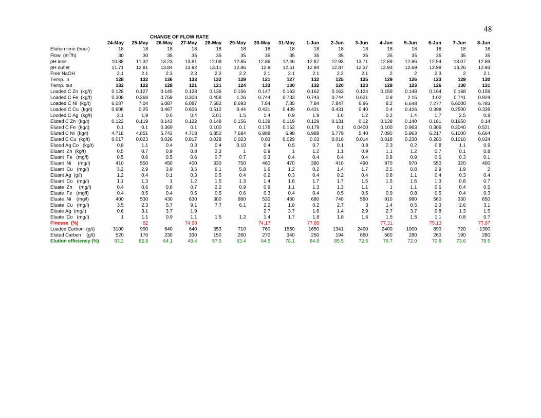
on (g/t) 3100 640 353 710 1550 1341 2400 1000 720Eluted Carbon (g/t) 520 170 230 330 150 260 270 340 250 194 660 560 280 260 190 280Elution efficiency (%) 83.2 82.8 64.1 48.4 57.5 63.4 64.5 78.1 84.8 85.5 72.5 76.7 72.0 70.8 73.6 78.5
CHANGE OF FLOW RATE24-May 25-May 26-May 27-May 28-May 29-May 30-May 31-May 1-Jun 2-Jun 3-Jun 4-Jun 5-Jun 6-Jun 7-Jun 8-Jun
Elution time (hour) 18 18 18 18 18 18 18 18 18 18 18 18 18 18 18 18Flow (m3/h) 30 30 35 35 35 35 35 35 35 35 35 35 35 35 35 35pH inlet 10.88 11.32 13.23 13.81 12.08 12.85 12.86 12.46 12.87 12.93 13.71 12.89 12.86 12.94 13.07 12.89pH outlet 11.71 12.81 13.84 13.92 13.11 12.86 12.8 12.51 12.94 12.87 12.37 12.93 12.69 12.98 13.26 12.93Free NaOH 2.1 2.1 2.3 2.3 2.2 2.2 2.1 2.1 2.1 2.2 2.1 2 2 2.3 2 2.1Temp. in 128 132 136 133 132 129 121 127 132 125 135 129 126 123 129 130Temp. out 132 122 128 121 121 124 133 130 132 120 123 128 123 126 130 131Loaded C Zn (kg/t) 0.128 0.127 0.145 0.128 0.136 0.156 0.147 0.163 0.162 0.163 0.124 0.159 0.148 0.164 0.168 0.159Loaded C Fe (kg/t) 0.308 0.268 0.759 0.308 0.458 1.26 0.744 0.733 0.743 0.744 0.621 0.9 2.15 1.02 0.741 0.924Loaded C Ni (kg/t) 6.087 7.04 6.087 6.087 7.582 8.693 7.84 7.85 7.84 7.847 6.96 8.2 6.648 7.277 6.6000 6.783Loaded C Cu (kg/t) 0.606 0.25 0.467 0.606 0.512 0.44 0.431 0.439 0.431 0.431 0.40 0.4 0.426 0.398 0.2500 0.339Looded C Ag (kg/t) 2.1 1.9 0.6 0.4 2.01 1.5 1.4 0.9 1.9 1.6 1.2 0.2 1.4 1.7 2.5 0.8Eluted C Zn (kg/t) 0.122 0.119 0.143 0.122 0.148 0.156 0.139 0.119 0.129 0.131 0.12 0.138 0.140 0.161 0.1650 0.14Eluted C Fe (kg/t) 0.1 0.1 0.369 0.1 0.100 0.1 0.178 0.152 0.179 0.1 0.0400 0.100 0.963 0.306 0.3040 0.521Eluted C Ni (kg/t) 4.718 4.851 5.742 4.718 6.852 7.684 6.988 6.98 6.988 5.779 5.40 7.095 5.963 6.217 6.1000 6.664Eluted C Cu (kg/t) 0.017 0.023 0.026 0.017 0.028 0.023 0.03 0.029 0.03 0.016 0.014 0.018 0.230 0.280 0.1010 0.024Eluted Ag Co (kg/t) 0.8 1.1 0.4 0.3 0.4 0.10 0.4 0.5 0.7 0.1 0.8 2.3 0.2 0.8 1.1 0.9Eluant Zn (kg/t) 0.5 0.7 0.9 0.8 2.3 1 0.9 1 1.2 1.1 0.9 1.1 1.2 0.7 0.1 0.8Eluant Fe (mg/l) 0.5 0.6 0.5 0.6 0.7 0.7 0.3 0.4 0.4 0.4 0.4 0.8 0.9 0.6 0.3 0.1Eluant Ni (mg/l) 410 550 450 400 330 750 460 470 380 410 490 970 970 550 320 400Eluant Cu (mg/l) 3.2 2.9 3.9 3.5 6.1 5.8 1.6 1.2 0.2 1.4 1.7 2.5 0.8 2.9 1.9 2Eluant Ag (g/l) 1.2 0.4 0.1 0.3 0.5 0.4 0.2 0.3 0.4 0.2 0.4 0.8 1.1 0.4 0.3 0.4Eluant Co (mg/l) 1.1 1.3 1 1.2 1.5 1.3 1.4 1.6 1.7 1.7 1.5 1.5 1.6 1.3 0.8 0.7Eluate Zn (mg/l) 0.4 0.6 0.8 0.7 2.2 0.9 0.9 1.1 1.3 1.3 1.1 1 1.1 0.6 0.4 0.5Eluate Fe (mg/l) 0.4 0.5 0.4 0.5 0.5 0.6 0.3 0.4 0.4 0.5 0.5 0.9 0.8 0.5 0.4 0.3Eluate Ni (mg/l) 400 530 430 630 300 980 530 430 680 740 560 910 980 560 330 650Eluate Cu (mg/l) 3.5 2.3 5.7 9.1 7.7 6.1 2.2 1.8 0.2 2.7 3 1.4 0.5 2.3 2.6 3.1Eluate Ag (mg/l) 0.6 3.1 3.7 1.9 2.7 3.7 1.6 1.4 2.9 2.7 3.7 0.8 1.3 1.5Eluate Co (mg/l) 1 1.1 0.9 1.1 1.5 1.2 1.4 1.7 1.8 1.8 1.6 1.5 1.5 1.1 0.8 0.7Finesse (%) 82 74.98 74.17 77.88 77.31 75.13 77.87Loaded Carb 990 640 760 1650 2400 890 1300

49
o n ( g / t ) 6 8 0 1 1 0 0 9 1 0 7 1 0 1 0 0 0 9 8 0 9 8 0 9 6 0 8 5 0 8 9 0E lu t e d C a r b o n ( g / t ) 1 8 0 3 5 0 3 3 0 2 4 0 4 5 0 3 4 0 2 8 0 2 4 0 3 8 0 3 8 0 1 9 0 2 5 0 8 0 1 5 0 1 2 0 1 7 0E l u t i o n e f f i c i e n c y ( % ) 7 3 . 5 6 8 . 2 7 0 . 0 7 3 . 6 7 0 . 0 5 2 . 1 8 1 . 9 7 6 . 0 6 1 . 2 6 1 . 2 8 0 . 6 8 2 . 4 9 1 . 7 8 4 . 2 8 5 . 9 8 0 . 9
C H A N G E O F F L O W R9 - J u n 1 0 - J u n 1 1 - J u n 1 2 - J u n 1 3 - J u n 1 4 - J u n 1 5 - J u n 1 6 - J u n 1 7 - J u n 1 8 - J u n 1 9 - J u n 2 0 - J u n 2 1 - J u n 2 2 - J u n 2 3 - J u n 2 4 - J u n
E lu t io n t im e ( h o u r ) 1 8 1 8 1 8 1 8 1 8 1 8 1 8 1 8 1 8 1 8 1 8 1 8 1 8 1 8 1 8 1 8F lo w ( m 3 / h ) 3 5 3 5 3 5 3 5 3 5 3 5 3 5 3 5 3 5 3 5 2 5 2 5 2 5 2 5 2 5 2 5p H in le t 1 2 . 8 6 1 2 . 4 8 1 2 . 4 8 1 2 . 6 3 1 2 . 8 7 1 3 . 1 2 1 2 . 8 8 1 2 . 8 9 1 2 . 9 6 1 2 . 8 6 1 2 . 5 4 1 2 . 9 8 1 3 . 0 1 1 2 . 4 8 1 2 . 3 1 2 . 4 1p H o u t le t 1 2 . 8 3 1 2 . 4 8 1 2 . 4 1 2 . 8 4 1 2 . 8 9 1 2 . 0 5 1 2 . 8 2 1 2 . 8 7 1 2 . 9 2 1 2 . 7 9 1 2 . 5 1 1 2 . 9 7 1 2 . 8 1 1 2 . 4 3 1 2 . 3 8 1 2 . 3 6F r e e N a O H 2 2 . 2 2 . 2 2 . 1 2 . 1 2 . 2 2 . 1 2 2 . 1 2 . 2 2 . 2 2 . 1 2 . 2 2 . 1 1 . 8 2 . 2T e m p . in 1 2 0 1 2 5 1 2 0 1 2 9 1 2 6 1 3 3 1 3 0 1 2 8 1 2 8 1 2 3 1 2 8 1 2 8 1 2 9 1 1 0 1 0 4 1 0 0T e m p . o u t 1 2 1 1 2 8 1 2 2 1 2 9 1 2 4 1 2 9 1 2 9 1 2 6 1 2 6 1 2 2 1 2 7 1 2 4 1 2 3 1 1 6 1 1 5 1 2 6L o a d e d C Z n ( k g / t ) 0 . 1 6 1 0 . 1 3 6 0 . 1 8 0 . 1 4 1 0 . 1 3 7 0 . 1 4 2 0 . 1 3 9 0 . 1 4 0 . 1 2 4 0 . 1 4 9 0 . 1 7 4 0 . 1 3 4 0 . 1 6 4 0 . 2 6 1 0 . 1 8 3 0 . 1 7 8L o a d e d C F e ( k g / t ) 0 . 9 1 3 0 . 4 7 5 0 . 6 0 6 1 . 6 4 7 0 . 8 4 1 0 . 8 4 5 1 . 6 5 1 . 8 5 0 . 6 2 1 1 . 8 9 0 . 4 4 6 0 . 5 2 6 1 . 1 3 3 0 . 6 6 8 0 . 8 2 3 0 . 2 3 4L o a d e d C N i ( k g / t ) 7 . 4 9 9 6 . 9 7 . 7 3 9 6 . 8 8 6 . 9 6 9 6 . 6 5 6 7 . 5 4 9 6 . 1 8 5 6 . 9 6 7 . 5 5 8 7 . 3 8 2 6 . 3 1 1 7 . 3 2 6 . 9 8 1 7 . 1 6 2 6 . 8 3L o a d e d C C u ( k g / t ) 0 . 1 9 2 0 . 3 0 . 3 2 7 0 . 2 6 3 0 . 3 1 6 0 . 2 5 0 . 3 5 0 . 3 0 8 0 . 4 0 0 . 4 6 2 0 . 3 5 9 0 . 4 6 2 0 . 4 7 2 0 . 4 8 6 0 . 5 2 5 0 . 5 4 1L o o d e d C A g ( k g / t ) 2 . 9 1 . 9 2 1 . 3 1 . 3 1 1 . 2 1 . 5 1 . 3 1 . 4 1 . 6 1 . 7 1 . 7 1 . 5 1 . 5 1 . 6E lu t e d C Z n ( k g / t ) 0 . 1 6 1 0 . 1 3 5 0 . 1 6 0 . 1 4 0 . 1 3 6 0 . 1 3 0 . 1 2 9 0 . 1 1 1 0 . 1 2 0 . 1 2 9 0 . 1 6 3 0 . 1 2 9 0 . 1 2 8 0 . 1 3 6 0 . 1 3 7 0 . 1 7 8E lu t e d C F e ( k g / t ) 0 . 1 0 0 0 . 0 1 9 0 . 5 0 8 0 . 9 8 2 0 . 8 3 9 0 . 4 6 9 1 . 4 5 0 . 6 8 7 0 . 0 4 0 . 6 0 2 0 . 4 4 6 0 . 4 2 3 0 . 4 1 1 0 . 4 0 8 0 . 5 5 3 0 . 2 3 1E lu t e d C N i ( k g / t ) 6 . 2 9 5 5 . 8 6 . 7 1 6 . 2 7 6 5 . 6 9 6 6 . 2 5 7 . 1 2 8 6 . 1 1 9 5 . 4 0 6 . 3 7 4 . 8 9 5 4 . 1 8 4 5 . 7 1 6 4 . 6 1 9 5 . 4 7 2 5 . 2E lu t e d C C u ( k g / t ) 0 . 0 2 6 0 . 0 1 6 0 . 0 2 1 0 . 0 2 1 0 . 0 5 2 0 . 0 6 0 . 3 3 0 . 0 2 9 0 . 0 1 4 0 . 0 2 5 0 . 0 2 3 0 . 2 2 0 . 0 3 0 . 0 3 1 0 . 0 9 6 0 . 0 2 3E lu t e d A g C o ( k g / t ) 0 . 9 0 . 4 0 . 1 0 . 5 0 . 1 0 . 2 0 . 4 0 . 3 0 . 3 0 . 2 0 . 5 0 . 2 0 . 1 0 . 4 0 . 1 0 . 3E lu a n t Z n ( k g / t ) 2 . 3 0 . 2 0 . 8 1 . 1 0 . 9 0 . 9 0 . 4 0 . 1 0 . 5 0 . 3 0 . 4 0 . 2 0 . 5 0 . 8 0 . 1 0 . 8E lu a n t F e ( m g / l ) 6 9 0 0 . 1 0 . 1 0 . 7 0 . 4 0 . 3 2 . 3 1 . 2 0 . 1 1 . 4 1 . 6 1 . 1 1 . 3 1 . 6 1 . 1 0 . 1E lu a n t N i ( m g / l ) 3 . 1 3 8 0 4 0 0 5 5 0 4 9 0 4 6 0 6 9 0 2 8 0 3 5 0 2 9 0 3 6 0 5 1 0 3 8 0 5 2 0 3 8 0 4 0 0E lu a n t C u ( m g / l ) 1 . 3 4 . 6 2 0 . 6 1 . 7 1 . 6 1 . 3 1 . 9 3 . 4 0 0 . 6 0 . 7 3 . 1 2 . 1 3 . 7 3 . 1 2E lu a n t A g ( g / l ) 0 . 5 0 . 6 0 . 8 0 . 7 0 . 7 0 . 6 0 . 8 1 . 5 1 . 3 0 . 8 0 . 6 0 . 7 0 . 1 0 . 5 0 . 1 0 . 2E lu a n t C o ( m g / l ) 0 . 4 0 . 7 0 . 7 2 . 9 1 . 5 1 . 4 0 . 4 0 . 6 0 . 7 0 . 6 0 . 7 0 . 5 0 . 6 0 . 8 0 . 7 0 . 7E lu a t e Z n ( m g / l ) 2 . 3 0 . 2 0 . 4 1 . 3 1 . 1 0 . 9 2 . 3 0 . 1 0 . 6 0 . 3 0 . 3 0 . 2 0 . 5 0 . 2 0 . 1 0 . 4E lu a t e F e ( m g / l ) 7 6 0 0 . 1 0 . 1 0 . 6 0 . 4 0 . 3 2 . 3 1 . 2 0 . 1 1 . 4 1 . 5 0 . 9 1 . 2 1 . 6 1 . 4 0 . 1E lu a t e N i ( m g / l ) 3 . 8 4 8 0 4 2 0 5 7 0 5 1 0 5 6 0 7 6 0 3 9 0 3 9 0 3 4 0 6 9 0 9 5 0 8 2 0 9 7 0 8 5 0 7 2 0E lu a t e C u ( m g / l ) 0 . 8 0 . 1 3 2 . 1 3 2 . 2 0 . 8 4 . 8 2 . 8 1 . 2 1 . 1 4 . 2 3 . 4 5 . 4 3 . 1 3E lu a t e A g ( m g / l ) 1 . 6 1 . 3 1 . 2 1 . 4 2 . 2 2 . 3 1 . 6 1 . 8 2 . 0 1 1 . 3 1 . 5 1 . 2 2 . 7 2 . 9 2 . 0 0 3 . 7E lu a t e C o ( m g / l ) 0 . 6 0 . 4 0 . 7 2 . 3 1 . 6 1 . 4 0 . 6 0 . 7 0 . 6 0 . 7 0 . 5 0 . 7 0 . 8 0 . 7F i n e s s e ( % ) 7 8 . 8 7 7 4 . 2 4 7 5 . 6 4 7 5 . 3 9 7 0 . 7 7 7 3 . 9 7L o a d e d C a r b 1 1 0 0 1 5 0 0 1 5 5 0 9 8 0 1 4 2 0 9 5 0

50Cleaned No2 Eluant tank
26-Jun 27-Jun 28-Jun 29-Jun 30-Jun 1-Jul 2-Jul 3-Jul 4-Jul 5-Jul 6-Jul 7-Jul 8-Jul 9-Jul 10-Jul 11-JulElution time (hour) 18 18 18 18 18 18 18 18 18 18 18 18 18 18 18 18Flow (m3/h) 25 25 25 35 35 30 30 30 30 30 30 30 30 30 30 30pH inlet 12.87 12.54 12.14 12.39 12.93 12.68 12.1 13.52 13.45 12.86 12.93 12.41 12.46 12.94 12.99 12.95pH outlet 12.83 12.56 11.99 12.36 13 12.5 12.2 13.05 13.32 12.69 12.89 12.45 12.4 12.89 12.96 12.89Free NaOH 2.1 2.1 2.1 2.2 2 2 2 2.1 2.4 2.1 2 2.1 2 2.2 2.1 2.1Temp. in 121 100 112 114 131 120 128 127 129 130 131 116 129 131 130 131Temp. out 130 132 126 127 132 126 127 128 128 131 128 124 126 130 131 129Loaded C Zn (kg/t) 0.151 0.123 0.139 0.156 0.668 0.178 0.724 0.888 0.139 0.161 0.18 0.139 0.134 0.149 0.123 0.668Loaded C Fe (kg/t) 0.825 0.205 6.939 1.26 1.246 0.234 11.89 0.301 1.65 0.913 0.606 1.65 0.526 0.768 0.205 1.246Loaded C Ni (kg/t) 6.991 6.703 6.612 8.693 5.63 6.83 7.033 5.474 7.549 7.499 7.739 7.549 6.311 7.28 6.703 5.63Loaded C Cu (kg/t) 0.439 0.435 0.554 0.45 0.037 0.4 0.414 0.061 0.35 0.192 0.327 0.35 0.462 0.624 0.435 0.037Looded C Ag (kg/t) 1.2 1.4 2.2 2.3 1.6 1.8 2.01 1.3 1.5 1.200 1.3 1.4 2.1 1.9 0.6 0.4Eluted C Zn (kg/t) 0.124 0.121 0.135 0.156 0.122 0.178 0.142 0.13 0.129 0.161 0.16 0.129 0.129 0.139 0.121 0.122Eluted C Fe (kg/t) 0.329 0.169 3.112 0.1 1.102 0.231 6.821 0.086 1.45 0.100 0.508 1.45 0.423 0.526 0.169 1.102Eluted C Ni (kg/t) 5.144 4.919 4.262 7.684 3.292 6.2 4.568 3.126 7.128 6.295 6.71 7.128 4.184 5.398 4.919 3.292Eluted C Cu (kg/t) 0.019 0.024 0.022 0.021 0.025 0.023 0.061 0.016 0.33 0.026 0.021 0.33 0.22 0.038 0.024 0.025Eluted Ag Co (kg/t) 0.4 0.2 0.3 0.4 0.2 0.2 0.6 0.4 0.3 0.3 0.4 0.5 0.7 0.2 0.1 0.4Eluant Zn (kg/t) 0.1 0.5 0.4 0.8 0.3 0.8 0.8 0.3 0.5 0.3 0.4 0.1 0.3 0.1 0.5 0.8Eluant Fe (mg/l) 0.3 2.2 2.3 1.6 0.8 0.1 1.6 0.8 0.1 1.4 1.6 0.2 0.8 1 2.2 1.6Eluant Ni (mg/l) 320 860 590 520 600 400 520 600 350 290 360 500 600 600 860 520Eluant Cu (mg/l) 1.9 0.6 2.1 2.7 2.9 2.00 3.7 2.9 3.40 0.6 0.7 2.5 2.9 3.7 0.6 2.7Eluant Ag (g/l) 0.3 0.3 0.2 2 0.6 2.7 0.6 0.2 0.8 0.1 0.3 0.5 0.8 0.5 0.8 0.5Eluant Co (mg/l) 0.8 1.5 1.3 0.8 0.6 0.7 0.8 0.6 0.7 0.6 0.7 0.6 0.6 0.7 1.5 0.8Eluate Zn (mg/l) 0.3 0.5 0.4 0.2 0.3 0.4 0.2 0.3 0.6 0.3 0.3 0.3 0.3 0.3 0.5 0.2Eluate Fe (mg/l) 0.3 2.4 2.3 1.6 1.2 0.1 1.6 1.2 1.3 1.3 1.4 0.4 1.2 1.7 2.4 1.6Eluate Ni (mg/l) 840 910 760 570 670 420 570 670 400 350 380 550 670 690 910 570Eluate Cu (mg/l) 4 1.3 3.8 5.4 3.8 3 5.4 3.8 2.8 1.2 1.1 3 3.8 4.3 1.3 5.4Eluate Ag (mg/l) 2.10 0.6 0.7 2.5 2.9 1.7 1.8 2.7 3.40 2 1.9 2.3 2.2 2.2 2.5 1.7Eluate Co (mg/l) 0.7 1.5 0.8 0.8 0.6 0.7 0.8 0.6 0.7 0.6 0.7 0.6 0.6 0.7 1.5 0.8Finesse (%) 70.8 80.12 89.71 77.64 72.58Loaded Carb 2050 730 730 870 50 250 670 2050
170 180 720on (g/t) 1250 1800 680 1200 21 1750 1 1250
Eluted Carbon (g/t) 140 90 370 220 140 360 160 60 240 240 340Elution efficiency (%) 88.8 95.0 82.0 67.6 76.7 75.3 83.9 70.0 92.6 96.6 80.8 80.8 49.3 64.9

51
bon (g/t) 780 920 1230 1600 640 660 720 730 480 790 910 930Eluted Carbon (g/t) 280 120 170 170 140 90 370 220 170 190 161 240 199 147 150 295 156Elution efficiency (%) 73.35 78.56 74.84 75.24 75.66 73.06 69.3 81 67.57 83.2
Change temperature close 12012-Jul 13-Jul 14-Jul 15-Jul 16-Jul 17-Jul 18-Jul 19-Jul 20-Jul 21-Jul 22-Jul 23-Jul 24-Jul 25-Jul 26-Jul 27-Jul 28-Jul 29-Jul 30-Jul 31-Jul 1-Aug
Elution time (hour) 18 18 18 18 18 18 18 18 18 18 18 18 18 18 18 18 18 18 18 18 18Flow (m3/h) 30 30 30 30 30 30 30 30 30 30 30 30 30 30 30 30 30 30 30 30 30pH inlet 12.56 12.68 12.91 12.92 12.86 12.74 12.97 12.94 12.96 12.8 12.3 12.94 12.89 12.41 12.65 12.89 12.94 12.96 11.36 11.45 10.95pH outlet 12.8 12.64 12.88 12.88 12.91 12.45 12.88 12.86 12.94 12.9 14.56 12.9 12.86 12.36 12.6 12.94 12.86 12.94 11.23 11.21 10.45Free NaOH 2.2 2.2 2.1 2.1 2.1 2.2 2.1 2.2 2 2 2.2 2.2 2.1 2.2 2.2 2.2 2.2 2 1.9 1.9 1.6Temp. in 106 130 130 130 110 127 119 120 120 121 121 132 130 119 118 121 120 120 129 120 120Temp. out 132 132 128 125 131 135 120 116 120 80 124 131 131 126 119 123 117 120 123 120 126Loaded C Zn (kg/t) 0.131 0.147 1.011 0.139 1.013 0.156 0.13 0.15 0.129 0.157 0.164 0.123 0.129 0.129 0.129 0.157 0.16 0.129 0.164 0.129 0.178Loaded C Fe (kg/t) 0.531 0.511 0.942 1.65 3.202 1.09 1.338 0.826 0.666 1.211 1.133 0.468 0.583 0.38 0.666 1.211 0.826 0.667 1.133 0.666 0.234Loaded C Ni (kg/t) 6.589 6.735 6.735 7.549 3.502 7.189 6.759 6.764 6.48 6.807 7.32 6.758 6.912 5.582 6.48 6.807 6.74 6.52 6.32 6.251 5.31Loaded C Cu (kg/t) 0.435 0.374 0.374 0.35 0.894 0.42 0.368 0.348 0.377 0.416 0.472 0.389 0.369 0.419 0.377 0.416 0.351 3.77 0.472 0.377 0.541Looded C Ag (kg/t) 2.01 1.5 1.4 0.9 1.9 1.4 1.5 3.1 1.5 2.1 1.6 1.4 1.5 1.8 1.6 1.1 1.2 1.5 1.4 1.3 1.5Eluted C Zn (kg/t) 0.01 0.143 0.141 0.129 0.989 0.156 0.123 0.144 0.116 0.125 0.116 0.108 0.122 0.99 0.125 0.108 0.144 0.116 0.128 0.116 0.178Eluted C Fe (kg/t) 0.244 0.317 0.815 0.508 0.513 0.585 0.881 0.556 0.283 0.442 0.283 0.406 0.517 0.241 0.442 0.406 0.556 0.287 0.411 0.283 0.231Eluted C Ni (kg/t) 0.011 6.128 3.068 6.71 3.068 6.98 5.619 6.553 6.169 6.626 6.169 5.66 5.276 5.282 6.626 5.66 6.553 6.185 5.716 6.169 5.2Eluted C Cu (kg/t) 0.017 0.028 0.059 0.021 0.059 0.019 0.135 0.017 0.377 0.016 0.377 0.024 0.021 0.025 0.016 0.024 0.017 0.377 0.03 0.377 0.023Eluted Ag Co (kg/t) 0.8 0.9 0.8 0.7 0.3 0.5 0.3 0.4 0.1 0.3 0.1 0.5 0.8 0.8 0.5 0.3 0.4 0.2 0.5 0.8 0.1Eluant Zn (kg/t) 0.8 0.3 0.5 0.8 0.3 0.1 0.2 0.9 1.2 0.8 1.1 0.4 0.3 0.2 0.8 0.1 0.3 0.5 0.8 0.5 0.8Eluant Fe (mg/l) 1.6 1.4 1.3 1.6 0.8 0.2 0.1 0.3 0.9 0.1 0.7 2.3 1.4 1.1 1.6 0.3 1.4 1.3 0.1 2.2 1.6Eluant Ni (mg/l) 520 290 380 520 600 500 300 460 970 400 550 690 290 510 520 320 290 380 400 860 520Eluant Cu (mg/l) 3.7 0.6 2.1 3.7 2.9 2.5 2.3 1.6 1.5 2 1.1 1.3 0.6 3.1 3.7 1.9 0.6 2.1 2 0.6 2.7Eluant Ag (g/l) 0.8 0.8 0.3 0.4 0.3 0.8 0.8 1.2 0.4 0.3 0.5 0.3 0.4 0.1 0.3 0.1 0.5 0.8 0.8 0.5 0.3Eluant Co (mg/l) 0.8 0.6 0.6 0.8 0.6 0.6 0.8 1.4 1.6 0.7 2.9 0.4 0.6 0.5 0.8 0.8 0.6 0.6 0.7 1.5 0.8Eluate Zn (mg/l) 0.2 0.3 0.5 0.2 0.3 0.3 0.5 0.9 1.1 0.5 1.3 2.3 0.3 0.2 0.2 0.3 0.3 0.5 0.4 0.5 0.2Eluate Fe (mg/l) 1.6 1.3 1.2 1.6 1.2 0.4 0.2 0.3 0.8 0.3 0.6 2.3 1.4 0.9 1.6 0.3 1.4 1.2 0.1 2.4 1.6Eluate Ni (mg/l) 570 350 820 570 670 550 410 530 980 650 570 760 340 950 970 840 340 820 720 910 570Eluate Cu (mg/l) 5.4 1.2 3.4 5.4 3.8 3 3.7 2.2 0.5 3.1 2.1 0.8 1.2 4.2 5.4 4 1.2 3.4 3 1.3 5.4Eluate Ag (mg/l) 1.6 2 2.5 2.2 1.9 2.7 3.7 1.6 1.4 2.9 2.7 3.7 0.8 1.3 1.4 1.3 1.5 1.8 1.4 1.1 1.5Eluate Co (mg/l) 0.8 0.6 0.7 0.8 0.6 0.6 0.8 1.4 1.5 0.7 2.3 0.6 0.6 0.5 0.8 0.7 0.6 0.7 0.7 1.5 0.8Finesse (%) 81.45 83.1 82.98 85.23 86.12 81.57 84.87 82.4 83.21Loaded Car 1950 790 1050 860 660 740 690 910 1400
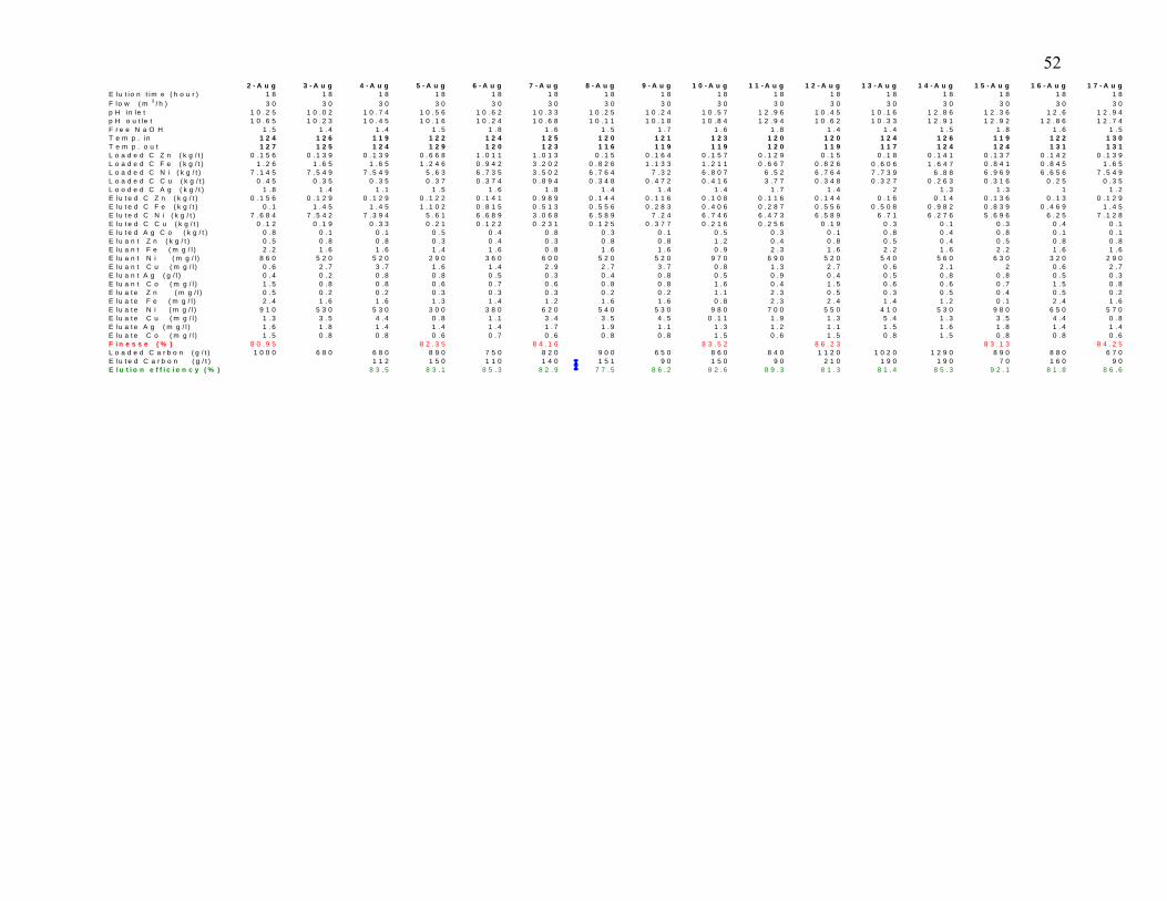
52
o n ( g / t ) 6 8 0 6 8 0 7 5 0 9 0 0 6 5 0 8 4 0 1 0 2 0 1 2 9 0 8 8 0E lu t e d C a r b o n ( g / t ) 1 1 2 1 5 0 1 1 0 1 4 0 1 5 1 9 0 1 5 0 9 0 2 1 0 1 9 0 1 9 0 7 0 1 6 0 9 0E l u t i o n e f f i c i e n c y ( % ) 8 3 . 5 8 3 . 1 8 5 . 3 8 2 . 9 7 7 . 5 8 6 . 2 8 2 . 6 8 9 . 3 8 1 . 3 8 1 . 4 8 5 . 3 9 2 . 1 8 1 . 8 8 6 . 6
2 - A u g 3 - A u g 4 - A u g 5 - A u g 6 - A u g 7 - A u g 8 - A u g 9 - A u g 1 0 - A u g 1 1 - A u g 1 2 - A u g 1 3 - A u g 1 4 - A u g 1 5 - A u g 1 6 - A u g 1 7 - A u gE lu t io n t im e ( h o u r ) 1 8 1 8 1 8 1 8 1 8 1 8 1 8 1 8 1 8 1 8 1 8 1 8 1 8 1 8 1 8 1 8F lo w ( m 3 / h ) 3 0 3 0 3 0 3 0 3 0 3 0 3 0 3 0 3 0 3 0 3 0 3 0 3 0 3 0 3 0 3 0p H in le t 1 0 . 2 5 1 0 . 0 2 1 0 . 7 4 1 0 . 5 6 1 0 . 6 2 1 0 . 3 3 1 0 . 2 5 1 0 . 2 4 1 0 . 5 7 1 2 . 9 6 1 0 . 4 5 1 0 . 1 6 1 2 . 8 6 1 2 . 3 6 1 2 . 6 1 2 . 9 4p H o u t le t 1 0 . 6 5 1 0 . 2 3 1 0 . 4 5 1 0 . 1 6 1 0 . 2 4 1 0 . 6 8 1 0 . 1 1 1 0 . 1 8 1 0 . 8 4 1 2 . 9 4 1 0 . 6 2 1 0 . 3 3 1 2 . 9 1 1 2 . 9 2 1 2 . 8 6 1 2 . 7 4F r e e N a O H 1 . 5 1 . 4 1 . 4 1 . 5 1 . 8 1 . 6 1 . 5 1 . 7 1 . 6 1 . 8 1 . 4 1 . 4 1 . 5 1 . 8 1 . 6 1 . 5T e m p . in 1 2 4 1 2 6 1 1 9 1 2 2 1 2 4 1 2 5 1 2 0 1 2 1 1 2 3 1 2 0 1 2 0 1 2 4 1 2 6 1 1 9 1 2 2 1 3 0T e m p . o u t 1 2 7 1 2 5 1 2 4 1 2 9 1 2 0 1 2 3 1 1 6 1 1 9 1 1 9 1 2 0 1 1 9 1 1 7 1 2 4 1 2 4 1 3 1 1 3 1L o a d e d C Z n ( k g / t ) 0 . 1 5 6 0 . 1 3 9 0 . 1 3 9 0 . 6 6 8 1 . 0 1 1 1 . 0 1 3 0 . 1 5 0 . 1 6 4 0 . 1 5 7 0 . 1 2 9 0 . 1 5 0 . 1 8 0 . 1 4 1 0 . 1 3 7 0 . 1 4 2 0 . 1 3 9L o a d e d C F e ( k g / t ) 1 . 2 6 1 . 6 5 1 . 6 5 1 . 2 4 6 0 . 9 4 2 3 . 2 0 2 0 . 8 2 6 1 . 1 3 3 1 . 2 1 1 0 . 6 6 7 0 . 8 2 6 0 . 6 0 6 1 . 6 4 7 0 . 8 4 1 0 . 8 4 5 1 . 6 5L o a d e d C N i ( k g / t ) 7 . 1 4 5 7 . 5 4 9 7 . 5 4 9 5 . 6 3 6 . 7 3 5 3 . 5 0 2 6 . 7 6 4 7 . 3 2 6 . 8 0 7 6 . 5 2 6 . 7 6 4 7 . 7 3 9 6 . 8 8 6 . 9 6 9 6 . 6 5 6 7 . 5 4 9L o a d e d C C u ( k g / t ) 0 . 4 5 0 . 3 5 0 . 3 5 0 . 3 7 0 . 3 7 4 0 . 8 9 4 0 . 3 4 8 0 . 4 7 2 0 . 4 1 6 3 . 7 7 0 . 3 4 8 0 . 3 2 7 0 . 2 6 3 0 . 3 1 6 0 . 2 5 0 . 3 5L o o d e d C A g ( k g / t ) 1 . 8 1 . 4 1 . 1 1 . 5 1 . 6 1 . 8 1 . 4 1 . 4 1 . 4 1 . 7 1 . 4 2 1 . 3 1 . 3 1 1 . 2E lu t e d C Z n ( k g / t ) 0 . 1 5 6 0 . 1 2 9 0 . 1 2 9 0 . 1 2 2 0 . 1 4 1 0 . 9 8 9 0 . 1 4 4 0 . 1 1 6 0 . 1 0 8 0 . 1 1 6 0 . 1 4 4 0 . 1 6 0 . 1 4 0 . 1 3 6 0 . 1 3 0 . 1 2 9E lu t e d C F e ( k g / t ) 0 . 1 1 . 4 5 1 . 4 5 1 . 1 0 2 0 . 8 1 5 0 . 5 1 3 0 . 5 5 6 0 . 2 8 3 0 . 4 0 6 0 . 2 8 7 0 . 5 5 6 0 . 5 0 8 0 . 9 8 2 0 . 8 3 9 0 . 4 6 9 1 . 4 5E lu t e d C N i ( k g / t ) 7 . 6 8 4 7 . 5 4 2 7 . 3 9 4 5 . 6 1 6 . 6 8 9 3 . 0 6 8 6 . 5 8 9 7 . 2 4 6 . 7 4 6 6 . 4 7 3 6 . 5 8 9 6 . 7 1 6 . 2 7 6 5 . 6 9 6 6 . 2 5 7 . 1 2 8E lu t e d C C u ( k g / t ) 0 . 1 2 0 . 1 9 0 . 3 3 0 . 2 1 0 . 1 2 2 0 . 2 3 1 0 . 1 2 5 0 . 3 7 7 0 . 2 1 6 0 . 2 5 6 0 . 1 9 0 . 3 0 . 1 0 . 3 0 . 4 0 . 1E lu t e d A g C o ( k g / t ) 0 . 8 0 . 1 0 . 1 0 . 5 0 . 4 0 . 8 0 . 3 0 . 1 0 . 5 0 . 3 0 . 1 0 . 8 0 . 4 0 . 8 0 . 1 0 . 1E lu a n t Z n ( k g / t ) 0 . 5 0 . 8 0 . 8 0 . 3 0 . 4 0 . 3 0 . 8 0 . 8 1 . 2 0 . 4 0 . 8 0 . 5 0 . 4 0 . 5 0 . 8 0 . 8E lu a n t F e ( m g / l ) 2 . 2 1 . 6 1 . 6 1 . 4 1 . 6 0 . 8 1 . 6 1 . 6 0 . 9 2 . 3 1 . 6 2 . 2 1 . 6 2 . 2 1 . 6 1 . 6E lu a n t N i ( m g / l ) 8 6 0 5 2 0 5 2 0 2 9 0 3 6 0 6 0 0 5 2 0 5 2 0 9 7 0 6 9 0 5 2 0 5 4 0 5 6 0 6 3 0 3 2 0 2 9 0E lu a n t C u ( m g / l ) 0 . 6 2 . 7 3 . 7 1 . 6 1 . 4 2 . 9 2 . 7 3 . 7 0 . 8 1 . 3 2 . 7 0 . 6 2 . 1 2 0 . 6 2 . 7E lu a n t A g ( g / l ) 0 . 4 0 . 2 0 . 8 0 . 8 0 . 5 0 . 3 0 . 4 0 . 8 0 . 5 0 . 9 0 . 4 0 . 5 0 . 8 0 . 8 0 . 5 0 . 3E lu a n t C o ( m g / l ) 1 . 5 0 . 8 0 . 8 0 . 6 0 . 7 0 . 6 0 . 8 0 . 8 1 . 6 0 . 4 1 . 5 0 . 6 0 . 6 0 . 7 1 . 5 0 . 8E lu a t e Z n ( m g / l ) 0 . 5 0 . 2 0 . 2 0 . 3 0 . 3 0 . 3 0 . 2 0 . 2 1 . 1 2 . 3 0 . 5 0 . 3 0 . 5 0 . 4 0 . 5 0 . 2E lu a t e F e ( m g / l ) 2 . 4 1 . 6 1 . 6 1 . 3 1 . 4 1 . 2 1 . 6 1 . 6 0 . 8 2 . 3 2 . 4 1 . 4 1 . 2 0 . 1 2 . 4 1 . 6E lu a t e N i ( m g / l ) 9 1 0 5 3 0 5 3 0 3 0 0 3 8 0 6 2 0 5 4 0 5 3 0 9 8 0 7 0 0 5 5 0 4 1 0 5 3 0 9 8 0 6 5 0 5 7 0E lu a t e C u ( m g / l ) 1 . 3 3 . 5 4 . 4 0 . 8 1 . 1 3 . 4 3 . 5 4 . 5 0 . 1 1 1 . 9 1 . 3 5 . 4 1 . 3 3 . 5 4 . 4 0 . 8E lu a t e A g ( m g / l ) 1 . 6 1 . 8 1 . 4 1 . 4 1 . 4 1 . 7 1 . 9 1 . 1 1 . 3 1 . 2 1 . 1 1 . 5 1 . 6 1 . 8 1 . 4 1 . 4E lu a t e C o ( m g / l ) 1 . 5 0 . 8 0 . 8 0 . 6 0 . 7 0 . 6 0 . 8 0 . 8 1 . 5 0 . 6 1 . 5 0 . 8 1 . 5 0 . 8 0 . 8 0 . 6F i n e s s e ( % ) 8 0 . 9 5 8 2 . 3 5 8 4 . 1 6 8 3 . 5 2 8 6 . 2 3 8 3 . 1 3 8 4 . 2 5L o a d e d C a r b 1 0 0 0 8 9 0 8 2 0 8 6 0 1 1 2 0 8 9 0 6 7 0
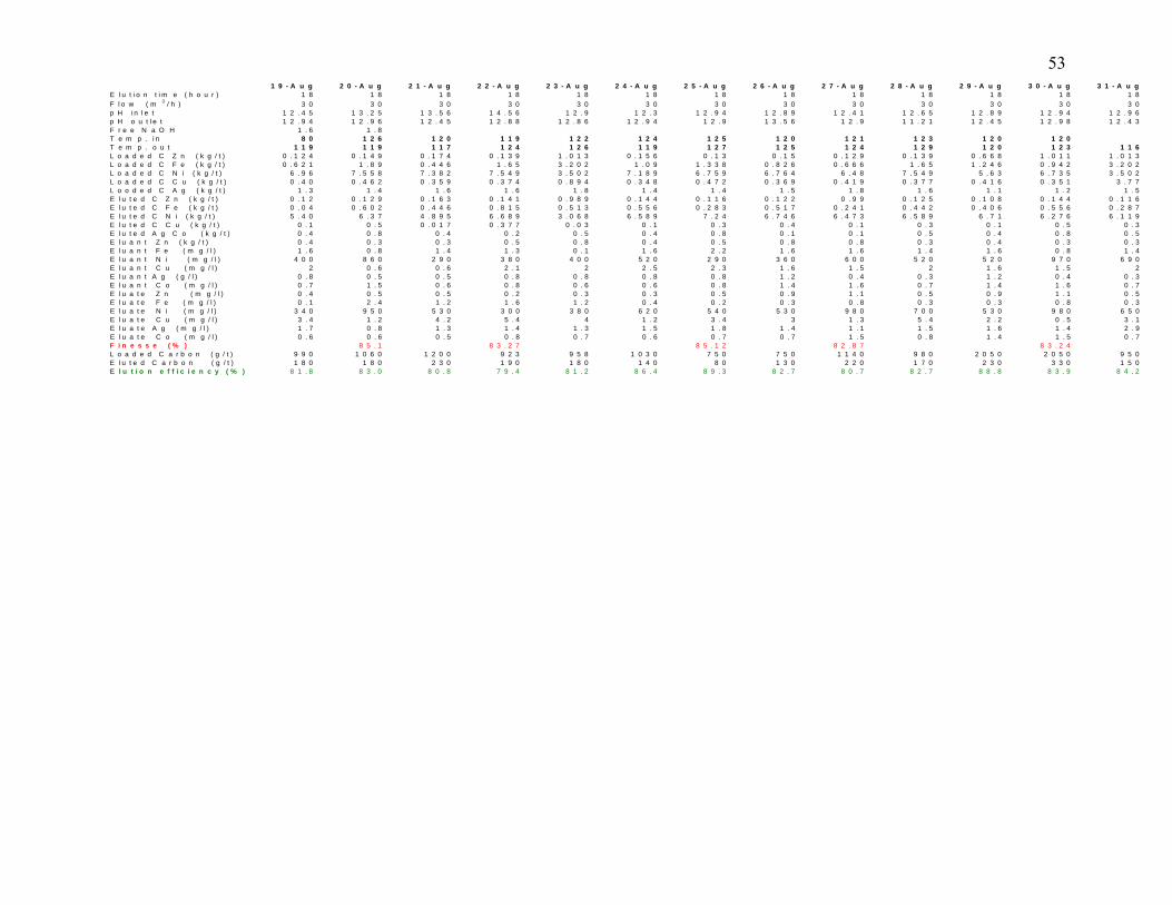
53
b o n ( g / t ) 9 9 0 1 2 0 0 9 5 8 1 0 3 0 7 5 0 9 8 0 2 0 5 0 9 5 0E l u t e d C a r b o n ( g / t ) 1 8 0 1 8 0 2 3 0 1 9 0 1 8 0 1 4 0 8 0 1 3 0 2 2 0 1 7 0 2 3 0 3 3 0 1 5 0E l u t i o n e f f i c i e n c y ( % ) 8 1 . 8 8 3 . 0 8 0 . 8 7 9 . 4 8 1 . 2 8 6 . 4 8 9 . 3 8 2 . 7 8 0 . 7 8 2 . 7 8 8 . 8 8 3 . 9 8 4 . 2
1 9 - A u g 2 0 - A u g 2 1 - A u g 2 2 - A u g 2 3 - A u g 2 4 - A u g 2 5 - A u g 2 6 - A u g 2 7 - A u g 2 8 - A u g 2 9 - A u g 3 0 - A u g 3 1 - A u gE l u t i o n t i m e ( h o u r ) 1 8 1 8 1 8 1 8 1 8 1 8 1 8 1 8 1 8 1 8 1 8 1 8 1 8F l o w ( m 3 / h ) 3 0 3 0 3 0 3 0 3 0 3 0 3 0 3 0 3 0 3 0 3 0 3 0 3 0p H i n l e t 1 2 . 4 5 1 3 . 2 5 1 3 . 5 6 1 4 . 5 6 1 2 . 9 1 2 . 3 1 2 . 9 4 1 2 . 8 9 1 2 . 4 1 1 2 . 6 5 1 2 . 8 9 1 2 . 9 4 1 2 . 9 6p H o u t l e t 1 2 . 9 4 1 2 . 9 6 1 2 . 4 5 1 2 . 8 8 1 2 . 8 6 1 2 . 9 4 1 2 . 9 1 3 . 5 6 1 2 . 9 1 1 . 2 1 1 2 . 4 5 1 2 . 9 8 1 2 . 4 3F r e e N a O H 1 . 6 1 . 8T e m p . i n 8 0 1 2 6 1 2 0 1 1 9 1 2 2 1 2 4 1 2 5 1 2 0 1 2 1 1 2 3 1 2 0 1 2 0T e m p . o u t 1 1 9 1 1 9 1 1 7 1 2 4 1 2 6 1 1 9 1 2 7 1 2 5 1 2 4 1 2 9 1 2 0 1 2 3 1 1 6L o a d e d C Z n ( k g / t ) 0 . 1 2 4 0 . 1 4 9 0 . 1 7 4 0 . 1 3 9 1 . 0 1 3 0 . 1 5 6 0 . 1 3 0 . 1 5 0 . 1 2 9 0 . 1 3 9 0 . 6 6 8 1 . 0 1 1 1 . 0 1 3L o a d e d C F e ( k g / t ) 0 . 6 2 1 1 . 8 9 0 . 4 4 6 1 . 6 5 3 . 2 0 2 1 . 0 9 1 . 3 3 8 0 . 8 2 6 0 . 6 6 6 1 . 6 5 1 . 2 4 6 0 . 9 4 2 3 . 2 0 2L o a d e d C N i ( k g / t ) 6 . 9 6 7 . 5 5 8 7 . 3 8 2 7 . 5 4 9 3 . 5 0 2 7 . 1 8 9 6 . 7 5 9 6 . 7 6 4 6 . 4 8 7 . 5 4 9 5 . 6 3 6 . 7 3 5 3 . 5 0 2L o a d e d C C u ( k g / t ) 0 . 4 0 0 . 4 6 2 0 . 3 5 9 0 . 3 7 4 0 . 8 9 4 0 . 3 4 8 0 . 4 7 2 0 . 3 6 9 0 . 4 1 9 0 . 3 7 7 0 . 4 1 6 0 . 3 5 1 3 . 7 7L o o d e d C A g ( k g / t ) 1 . 3 1 . 4 1 . 6 1 . 6 1 . 8 1 . 4 1 . 4 1 . 5 1 . 8 1 . 6 1 . 1 1 . 2 1 . 5E l u t e d C Z n ( k g / t ) 0 . 1 2 0 . 1 2 9 0 . 1 6 3 0 . 1 4 1 0 . 9 8 9 0 . 1 4 4 0 . 1 1 6 0 . 1 2 2 0 . 9 9 0 . 1 2 5 0 . 1 0 8 0 . 1 4 4 0 . 1 1 6E l u t e d C F e ( k g / t ) 0 . 0 4 0 . 6 0 2 0 . 4 4 6 0 . 8 1 5 0 . 5 1 3 0 . 5 5 6 0 . 2 8 3 0 . 5 1 7 0 . 2 4 1 0 . 4 4 2 0 . 4 0 6 0 . 5 5 6 0 . 2 8 7E l u t e d C N i ( k g / t ) 5 . 4 0 6 . 3 7 4 . 8 9 5 6 . 6 8 9 3 . 0 6 8 6 . 5 8 9 7 . 2 4 6 . 7 4 6 6 . 4 7 3 6 . 5 8 9 6 . 7 1 6 . 2 7 6 6 . 1 1 9E l u t e d C C u ( k g / t ) 0 . 1 0 . 5 0 . 0 1 7 0 . 3 7 7 0 . 0 3 0 . 1 0 . 3 0 . 4 0 . 1 0 . 3 0 . 1 0 . 5 0 . 3E l u t e d A g C o ( k g / t ) 0 . 4 0 . 8 0 . 4 0 . 2 0 . 5 0 . 4 0 . 8 0 . 1 0 . 1 0 . 5 0 . 4 0 . 8 0 . 5E l u a n t Z n ( k g / t ) 0 . 4 0 . 3 0 . 3 0 . 5 0 . 8 0 . 4 0 . 5 0 . 8 0 . 8 0 . 3 0 . 4 0 . 3 0 . 3E l u a n t F e ( m g / l ) 1 . 6 0 . 8 1 . 4 1 . 3 0 . 1 1 . 6 2 . 2 1 . 6 1 . 6 1 . 4 1 . 6 0 . 8 1 . 4E l u a n t N i ( m g / l ) 4 0 0 8 6 0 2 9 0 3 8 0 4 0 0 5 2 0 2 9 0 3 6 0 6 0 0 5 2 0 5 2 0 9 7 0 6 9 0E l u a n t C u ( m g / l ) 2 0 . 6 0 . 6 2 . 1 2 2 . 5 2 . 3 1 . 6 1 . 5 2 1 . 6 1 . 5 2E l u a n t A g ( g / l ) 0 . 8 0 . 5 0 . 5 0 . 8 0 . 8 0 . 8 0 . 8 1 . 2 0 . 4 0 . 3 1 . 2 0 . 4 0 . 3E l u a n t C o ( m g / l ) 0 . 7 1 . 5 0 . 6 0 . 8 0 . 6 0 . 6 0 . 8 1 . 4 1 . 6 0 . 7 1 . 4 1 . 6 0 . 7E l u a t e Z n ( m g / l ) 0 . 4 0 . 5 0 . 5 0 . 2 0 . 3 0 . 3 0 . 5 0 . 9 1 . 1 0 . 5 0 . 9 1 . 1 0 . 5E l u a t e F e ( m g / l ) 0 . 1 2 . 4 1 . 2 1 . 6 1 . 2 0 . 4 0 . 2 0 . 3 0 . 8 0 . 3 0 . 3 0 . 8 0 . 3E l u a t e N i ( m g / l ) 3 4 0 9 5 0 5 3 0 3 0 0 3 8 0 6 2 0 5 4 0 5 3 0 9 8 0 7 0 0 5 3 0 9 8 0 6 5 0E l u a t e C u ( m g / l ) 3 . 4 1 . 2 4 . 2 5 . 4 4 1 . 2 3 . 4 3 1 . 3 5 . 4 2 . 2 0 . 5 3 . 1E l u a t e A g ( m g / l ) 1 . 7 0 . 8 1 . 3 1 . 4 1 . 3 1 . 5 1 . 8 1 . 4 1 . 1 1 . 5 1 . 6 1 . 4 2 . 9E l u a t e C o ( m g / l ) 0 . 6 0 . 6 0 . 5 0 . 8 0 . 7 0 . 6 0 . 7 0 . 7 1 . 5 0 . 8 1 . 4 1 . 5 0 . 7F i n e s s e ( % ) 8 5 . 1 8 3 . 2 7 8 5 . 1 2 8 2 . 8 7 8 3 . 2 4L o a d e d C a r 1 0 6 0 9 2 3 7 5 0 1 1 4 0 2 0 5 0


![Yanacocha [Sólo lectura] Gold Mill_072005.pdf– 41.5 million tonnes ... Batu Hijau – Copper Sulfide Precipitation Filter Press Copper Sulfide product. July 13, 2005 CARBON ELUTION](https://img.dokumen.tips/doc/110x75/5e3e47331ce782481a666023/yanacocha-slo-lectura-gold-mill072005pdf-a-415-million-tonnes-batu.jpg)